Optimus PM-804 Manual de usuario
- Categoría
- Equipo de música suplementario
- Tipo
- Manual de usuario

MEZCLADOR
MATRICIAL 8x4
8x4 MATRIX MIXER
PM-804
WP-1
PM-4Z
Installation and
operating instructions

PM-804 Versión 1.0 Página 1 de 26
PM-804
Mezclador Matricial 8x4
INSTRUCCIONES DE SEGURIDAD:
INSTALACIÓN:
La instalación de este sistema es muy simple. Recomendamos que se tome su tiempo en leerse
este manual a fin de asegurarse de realizar una instalación correcta.
Nunca instale este equipo en un ambiente con altas temperaturas, polvo, humedad o vibraciones
ya que podría alterar su rendimiento o reducir su vida útil.
INSTRUCCIONES DE SEGURIDAD IMPORTANTES
1. Lea las instrucciones.
2. Guarde este manual.
3. Preste atención a todas las advertencias.
4. Siga las instrucciones.
5. No utilice este equipo cerca del agua.
6. Límpielo solamente con un paño seco.
7. No bloquee las aberturas de ventilación. Instale de acuerdo con las instrucciones del
fabricante.
8. No lo instale cerca de fuentes de calor tales como radiadores, calefactores, estufas u otros
aparatos (incluyendo amplificadores) que produzcan calor.
9. No anule la seguridad del enchufe polarizado o con toma de tierra. Un enchufe polarizado
tiene dos clavijas, una más ancha que la otra. Un enchufe tiene dos clavijas y una tercera
conectada a tierra. La tercera clavija se proporciona para su seguridad. Si el enchufe no
encaja en su toma de corriente, consulte a un electricista para que cambie su toma de
corriente obsoleta.
10. Evite que el cable de alimentación sea pisado o aplastado. Especialmente por la parte de
los enchufes.
11. Utilice sólo los accesorios especificados por el fabricante.
12. Utilice únicamente la carretilla, plataforma, trípode, soporte o mesa especificados por el
fabricante o vendidos con el equipo. Cuando utilice un carro tenga cuidado al mover el
conjunto carro + aparato para evitar lesiones por vuelco.
13. Desenchufe este equipo durante tormentas eléctricas o cuando no lo vaya a usar durante
largos periodos de tiempo.
14. Confíe todas las reparaciones a nuestro personal técnico cualificado. Se requiere servicio
técnico cuando el equipo ha sido dañado de alguna manera: el cable de alimentación o el
enchufe están dañados, se ha derramado líquido o han caído objetos dentro del equipo, el
equipo ha sido expuesto a la lluvia o a humedad, no funciona con normalidad o se ha
caído.

PM-804 Versión 1.0 Página 2 de 26
PM-804
Mezclador Matricial 8x4
Evite las altas temperaturas, la humedad, el polvo y las vibraciones:
Mantenga la unidad alejada de los lugares donde pudiera quedar expuesta a altas temperaturas o
humedad como cerca de radiadores, estufas… Evite también los lugares sujetos a la acumulación
excesiva de polvo o vibraciones ya que pueden causar daños mecánicos.
Evite golpes:
Los fuertes golpes pueden provocar daños en la unidad. Manipule la unidad con cuidado.
No abra la unidad por si mismo en un intento de reparación o modificación:
Confíe todas las reparaciones a personal de Optimus cualificado. Abrir la caja y/o la manipulación
de los circuitos internos anula la garantía.
Apague siempre la alimentación antes de realizar las conexiones:
Apague siempre la alimentación de CA antes de conectar o desconectar los cables. Esto es
importante para evitar daños en la propia unidad así como en otros equipos conectados.
Maneje los cables con cuidado:
Tire siempre del conector al conectar o desconectar los cables (incluyendo el cable de
alimentación), no del cable.
Limpie con un paño seco y suave:
No utilice disolventes como la gasolina o disolvente para pintura para limpiar la unidad. Use un
paño seco y suave.

PM-804 Versión 1.0 Página 3 de 26
PM-804
Mezclador Matricial 8x4
ÍNDICE
1. CONTROLES ............................................................................................................... 4
2. CONECTORES ............................................................................................................ 4
3. INDICADORES ............................................................................................................ 4
4. PANEL FRONTAL ....................................................................................................... 5
5. PANEL POSTERIOR ................................................................................................... 7
6. MANDO DE CONTROL MURAL WP-1 ....................................................................... 8
7. PUPITRE MICROFÓNICO DE 4 ZONAS PM-4Z ........................................................ 9
8. ESPECIFICACIONES TÉCNICAS PM-804 ............................................................... 11
9. ESPECIFICACIONES TÉCNICAS WP-1 ................................................................... 11
10. ESPECIFICACIONES TÉCNICAS PM-4Z ................................................................. 11
11. EJEMPLO DE CONEXIÓN. ....................................................................................... 12
12. CERTIFICADO DE GARANTÍA ................................................................................. 13

PM-804 Versión 1.0 Página 4 de 26
PM-804
Mezclador Matricial 8x4
1. CONTROLES
Panel frontal
CH1~4: Cuatro entradas de nivel Micro o Línea con 3 bandas de ecualización y selectores de
zona de salida.
CH5~8: Cuatro entradas de línea con selectores de zona de salida.
Control de nivel de salida con dos tonos de control e interruptor de mute.
Control de volumen para altavoz monitor con selectores de zona de salida.
Panel posterior
Ocho potenciómetros de volumen para cada entrada.
Interruptor de prioridad para la entrada CH1.
Interruptores de alimentación phantom para las entradas de micrófono: CH1 y CH2~4.
2. CONECTORES
Cuatro conectores XLR / Jack 6,35 balanceados electrónicamente para las entradas CH1~4.
Cuatro conectores Jack 6,35 / RCA para las entradas CH5~8.
Conector de entrada RJ45 para panel remoto WP-1 (entradas de fuente muscial y micrófono).
Terminal de 3 pines (H, C y GND) para las cuatro salidas.
Cuatro conectores de mute individuales y un conector de mute general.
3. INDICADORES
Alimentación, señal y pico para cada canal de entrada.
Señal, -20 dB, -10 dB, 0 dB y pico para cada canal de salida.

PM-804 Versión 1.0 Página 5 de 26
PM-804
Mezclador Matricial 8x4
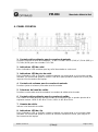
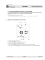
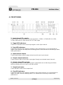
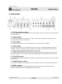
4. PANEL FRONTAL
1. Controles del ecualizador para los canales de entrada.
Permiten ecualizar la señal de entrada de: -12 dB a +12 dB a 80 Hz (LOW) a 2,5 kHz (MID) y a
12,5 kHz (HIGH) para las entradas CH1~CH4.
2. Indicadores LED de señal.
Estos indicadores LED muestran que hay señal de entrada en cada canal.
3. Indicadores LED de pico de señal.
Estos indicadores LED se iluminan cuando se detecta una sobrecarga en el canal de entrada
asociado. Se recomienda ajustar el control TRIM de la parte posterior cuando eso ocurra, para
mejorar el funcionamiento del equipo.
4. Controles de volumen para los canales de entrada.
Permiten ajustar el volumen para cada canal de entrada.
5. Selectores del canal de salida.
Permiten enrutar cada canal de entrada a los canales de salida seleccionados.
6. Controles del ecualizador para los canales de salida.
Los canales de salida disponen de dos bandas de ecualización que se pueden ajustar de la
siguiente manera: HIGH ±15 dB a 12 kHz / LOW ±15 dB a 80 Hz.
7. Vumeter de salida.
Indica el nivel de audio de salida.
8. Indicadores LED de clip.
Estos indicadores LED se iluminan cuando se detecta una sobrecarga en el canal de salida
asociado. Se recomienda ajustar el control de volumen cuando eso ocurra, para mejorar el
funcionamiento del equipo.

PM-804 Versión 1.0 Página 6 de 26
PM-804
Mezclador Matricial 8x4
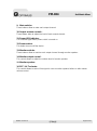
9. Pulsadores de Mute.
Estos botones permiten silenciar su canal de salida asociado.
10. Controles de volumen de salida.
Estos potenciómetros permiten ajustar el nivel del volumen de salida.
11. Indicador LED de alimentación.
Se ilumina cuando el equipo está encendido.
12. Interruptor de alimentación.
Enciende o apaga el equipo.
13. Botones de asignación del altavoz monitor.
Estos botones permiten monitorizar el audio de cada canal de salida por el altavoz monitor
integrado en la matriz.
14. Control de volumen del altavoz monitor.
Permite regular el volumen del altavoz monitor.
15. Altavoz monitor.
16. Selector PFC / ALT.
Permite seleccionar si la señal se manda al altavoz monitor antes o después de la regulación
del volumen master.

PM-804 Versión 1.0 Página 7 de 26
PM-804
Mezclador Matricial 8x4
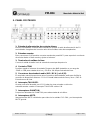
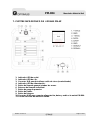
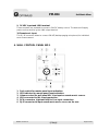
5. PANEL POSTERIOR
1. Entrada de alimentación de corriente alterna.
Esta es la entrada de corriente alterna donde se conecta el cable de alimentación de CA
suministrado. Asegúrese del correcto valor de los fusibles antes de reemplazarlos.
2. Entradas remotas.
Estos conectores RJ45 permiten conectar mandos de pared WP-1 para reproducir una fuente
de música desde un área remota y ajustar el volumen.
3. Terminales de salidas de línea.
Conecte la salida de audio hacia la entrada de una etapa de potencia.
4. Controles TRIM.
Permiten regular el volumen de entrada. Disponen de 44dB ajustables en un rango de
-50 dB a -6 dB para entrada de micro y -30 dB a +14 dB para entrada de línea.
5. Conectores de entrada de audio (XLR / RCA / Jack 6,35).
El mezclador matricial proporciona varios conectores de entrada de audio para facilitar la
conexión de dispositivos externos. CH1~4: Entrada balanceada de línea y micro / CH5~8:
Entrada mono de línea.
6. Interruptor TALKOVER.
Al entrar una señal de audio por el CH1, todas las otras entradas se silencian
automáticamente cuando el interruptor TALKOVER está en ON.
7. Interruptores PHANTOM.
Proporciona alimentación PHANTOM para cada entrada de micrófono.
8. Interruptores MUTE.
Interruptores de MUTE individuales para silenciar las salidas CH1~CH4 y un interruptor de
MUTE general.

PM-804 Versión 1.0 Página 8 de 26
PM-804
Mezclador Matricial 8x4
9. Conector de alimentación de 24VCC y Conector LINK.
Conecte una batería de 24 VCC al terminal de entrada de alimentación. El conector LINK se
usa para dar alimentación a otros equipos desde la misma batería.
10. Entrada para micrófono remoto.
Este conector RJ45 permite la conexión del pupitre microfónico de 4 zonas PM-4Z.
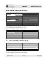
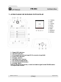
6. MANDO DE CONTROL MURAL WP-1
1. Interruptor de activación.
2. Indicador LED de activación
3. Control de volumen para micro y línea.
4. Conector XLR de entrada de micro.
5. Conectores RCA (derecho e izquierdo) para entrada de línea.
6. Conector de salida RJ45 para conectar el mando con la matriz PM-804.

PM-804 Versión 1.0 Página 9 de 26
PM-804
Mezclador Matricial 8x4
7. PUPITRE MICROFÓNICO DE 4 ZONAS PM-4Z
1. Indicador LED de señal.
2. Indicador LED de clip.
3. Conector XLR para micrófono cuello de cisne (suministrado).
4. Indicador LED de alimentación.
5. Botón de llamada general a todas las zonas.
6. Botones de llamada individual.
7. Botón de gong de preaviso.
8. Botón de hablar.
9. Botón de bloqueo.
10. Conector RJ45 para conectar alimentación, datos y audio a la matriz PM-804.
11. Control del nivel del audio de salida.

PM-804 Versión 1.0 Página 10 de 26
PM-804
Mezclador Matricial 8x4
FUNCIONAMIENTO DEL PUPITRE PM-4Z:
Pulse el botón de zona de la 1 a la 4 para lanzar un aviso de zona individual.
El indicador LED de la zona seleccionada se iluminará. Si no quiere lanzar un aviso
a la zona seleccionada, pulse de nuevo el mismo botón de zona.
Pulse el botón CHIME si quiere lanzar un gong de preaviso.
Pulse y mantenga el botón TALK para hablar.
No funcionará ningún botón de selección de zonas si el interruptor de la parte
posterior se encuentra en la posición LOCK.
El nivel de audio de salida se puede regular mediante el control de volumen
posterior.

PM-804 Versión 1.0 Página 11 de 26
PM-804
Mezclador Matricial 8x4
8. ESPECIFICACIONES TÉCNICAS PM-804
Nivel de salida / impedancia
0 dB / 600 Ω Balanceada
Sensibilidad de entrada /
Impedancia
Entrada de Micro
-60 dB ~ -16 dB / 20 kΩ Balanceada
Entrada de Línea
-20 dB ~ +4 dB / 20 kΩ Balanceada
Entrada Remota
0 dB / 600 Ω Balanceada
Respuesta en Frecuencia (-1dB)
20 Hz ~ 20 kHz
T.H.D.
< 0,1%
Crosstalk
>70 dB
Equalización
Entrada
High: 12 kHz ± 15 dB / Mid: 2,5 kHz ± 15 dB /
Low: 80 Hz ± 15 dB
Salida
High: 10 kHz ± 15 dB / Low: 100 Hz ± 15 dB
Relación Señal Ruido
>90 dB
Fuente de alimentación
100~240 VCA, 50~60 Hz / 24 VCC
Peso neto
9 kg
Dimensiones (ancho, alto, profundo)
420 x 88 x 320 mm
Estos parámetros pueden ser modificados sin previa notificación.
9. ESPECIFICACIONES TÉCNICAS WP-1
Nivel de salida / impedancia
1 dB / 600 Ω Balanceada
Sensibilidad de entrada /
Impedancia
Entrada de Micro
-50 dB ~ / 20 kΩ Balanceada
Entrada de Línea
0 dB ~ / 30 kΩ Balanceada
Respuesta en Frecuencia (-1dB)
20 Hz ~ 20 kHz
T.H.D.
< 0,1%
Relación señal Ruido
>100 dB
Fuente de alimentación
15 VCC
Peso neto
0,12 kg
Dimensiones (ancho, alto, profundo)
80 x 80 x 50 mm
10. ESPECIFICACIONES TÉCNICAS PM-4Z
Sensibilidad de entrada
-60 dB ± 3 dB / 600 Ω Balanceada
Respuesta en Frecuencia
45 Hz ~ 15 kHz / ± 1 dB
Relación señal Ruido
>90 dB
Nivel de salida
0 dB / 600 Ω Balanceada
T.H.D.
< 0,1% (a 1 kHz)
Temperatura de funcionamiento
0º ~ 40ºC con 95 % de humedad
Peso neto
0.9 kg
Dimensiones (ancho, alto, profundo)
140 x 60 x 205 mm
Estos parámetros pueden ser modificados sin previa notificación.

PM-804 Versión 1.0 Página 12 de 26
PM-804
Mezclador Matricial 8x4
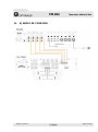
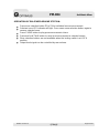
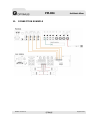
11. EJEMPLO DE CONEXIÓN

PM-804 Versión 1.0 Página 13 de 26
PM-804
Mezclador Matricial 8x4
12. CERTIFICADO DE GARANTÍA
1. La empresa OPTIMUS S.A. garantiza que sus productos se encuentran libres
de defectos en materiales y de mano de obra en el momento de su entrega
original al comprador.
2. La empresa OPTIMUS S.A. concede a sus productos, conforme a las
condiciones aquí descritas, una garantía de dos (2) años a partir de la fecha de
adquisición del producto por el comprador. Si, dentro de este plazo de garantía,
se producen defectos que no sean debidos a razones mencionadas bajo el punto
2, la empresa OPTIMUS S.A. remplazará o reparará el aparato utilizando piezas
de recambio equivalentes, nuevas o reconstruidas, según criterio propio. Si se
aplican piezas de recambio que constituyen una mejora del aparato, la empresa
OPTIMUS S.A. se reserva el derecho de cargar el coste adicional de estos
componentes al cliente.
3. No se concederán prestaciones de garantía distintas a las citadas.
4. Para la utilización de los derechos de garantía será requisito indispensable
presentar la factura de compra original o el certificado de garantía.
2. DISPOSICIONES DE GARANTÍA
1. Si el producto tuviera que ser modificado o adaptado para cumplir con los
requisitos locales en cuanto a técnica o seguridad, si no se trata del país para el
cual el producto fue concebido y fabricado originalmente, ello no se considera
como defecto de material o de fabricación. Por lo demás, la garantía no
comprende la realización de estas modificaciones o adaptaciones,
independientemente de si éstas hayan sido ejecutadas debidamente o no.
OPTIMUS S.A. tampoco asumirá costes en el marco de la garantía por este tipo
de modificaciones.
2. La garantía no dará derecho a inspección o mantenimiento gratuito o
reparación del aparato, particularmente si los defectos son debidos a uso
inapropiado. Los derechos de garantía tampoco abarcan defectos en piezas de
desgaste que sean debidos a un desgaste normal. Piezas de desgaste son, en
particular, potenciómetros, interruptores/teclas, y piezas similares.
3. La garantía no abarca los defectos en el equipo causados por:
Abuso o uso incorrecto del aparato para fines distintos a los previstos, en
incumplimiento de las instrucciones de servicio y de mantenimiento
especificadas en el Manual y/o Instrucciones Técnicas del equipo.
Conexión o uso del producto de una manera que no corresponda a los
requisitos técnicos o de seguridad del país en el cual se utiliza el aparato.
Instalación en condiciones distintas a los indicados en el Manual y/o
Instrucciones Técnicas.
Deficiencia o interrupciones tensión eléctrica o defectos de instalación que
impliquen uso en condiciones anormales.
Daños ocasionados por otros equipos interconectados al producto.
El uso o instalación de Software (programas), interfaces, partes o
suministros no proporcionados y/o autorizados por OPTIMUS S.A.
La no utilización de los embalajes originales para su transporte.
Daños causados por fuerza mayor u otras causas no imputables a
OPTIMUS S.A.
4. No están cubiertos por esta garantía los siguientes elementos:
Todas las superficies de plástico y todas las piezas expuestas al exterior
que hayan sido rayadas o dañadas debido al uso normal o anormal.
Las roturas, golpes, daños por caídas o ralladuras causadas por traslados
de cualquier naturaleza.
Defectos de daños derivados de pruebas, uso, mantenimiento, instalación
y ajustes inapropiados, o derivados de cualquier alteración o modificación
de cualquier tipo no realizada por en Servicio Autorizado por OPTIMUS
S.A. en cumplimiento de esta garantía.
Los daños personales o a la propiedad que pudieran causar el uso
indebido del equipo, incluyendo la falta de mantenimiento.
5. La garantía carecerá de validez cuando se observe:
Enmiendas o tachaduras en los datos del certificado de garantía o factura
de compra.
Falta de factura original o falta de fecha en la misma.
Falta de número de serie o lote en el equipo.
6. La garantía no cubre los desplazamientos por asistencias técnicas a excepción
de los motivados por incidencias ocurridas durante los tres primeros meses.
7. En el caso de ordenadores PC, la garantía no cubrirá la eliminación de virus
informáticos, restauración de programas por este motivo o la reinstalación del
disco provocada por el borrado del mismo.
8. Los derechos de garantía se anulan si el producto ha sido reparado o abierto
por un personal no autorizado OPTIMUS S.A. o por el propio cliente.
9. Si la empresa OPTIMUS S.A. estableciera al comprador del aparato que los
daños presentados no dan derecho a la reclamación de la garantía, los costes de
las prestaciones de revisión por parte de la empresa OPTIMUS S.A. correrán a
cargo del cliente.
10. Los productos sin derechos de garantía sólo se repararán contra pago de los
gastos por el cliente. En caso de ausencia de derechos de garantía, OPTIMUS
S.A. informará al cliente al respecto. Si, en un plazo de 6 semanas a partir de
esta comunicación, no recibimos ninguna orden de reparación escrita
confirmando la aceptación de los gastos, OPTIMUS S.A. devolverá el aparato en
cuestión al cliente. En este caso, los gastos de transporte y embalaje se
facturarán por separado y se cobrarán contra reembolso. En caso de expedición
de una orden de reparación, confirmando la asunción de los gastos, los gastos
de transporte y de embalaje se facturarán adicionalmente, igualmente por
separado.
11. En caso de necesidad de traslado al Centro de Servicio Autorizado, el
transporte será realizado por el responsable de la garantía, y serán a su cargo
los gastos de flete y seguro.
12. En caso de falla, OPTIMUS S.A. asegura al comprador la reparación y/o
reposición de partes para su correcto funcionamiento en un plazo no mayor a 30
días. No obstante, se deja aclarado que el plazo usual no supera los 30 días.
13. Todas las piezas o productos sustituidos al amparo de los servicios en
garantía pasarán a ser propiedad de OPTIMUS S.A.
3. TRANSFERENCIA DE LA GARANTÍA
La garantía se concede únicamente para el comprador original (cliente principal)
y es intransferible. Con excepción de la empresa OPTIMUS S.A., ningún tercero
(comerciantes, etc.) está autorizado a conceder garantía adicionales en nombre
de la empresa OPTIMUS S.A.
4. RECLAMACIONES POR DAÑOS Y PERJUICIOS
En caso de que OPTIMUS S.A. no pueda proporcionar un servicio de garantía
adecuado, el comprador no tendrá ningún derecho a reclamar indemnización
alguna por daños y perjuicios consecuentes. La responsabilidad de la empresa
OPTIMUS S.A. se limita en todo caso al precio de facturación del producto
5. RELACIÓN CON OTROS DERECHOS DE GARANTÍA Y CON EL DERECHO
NACIONAL
1. Mediante esta garantía no se afecta a los derechos del comprador frente al
vendedor deducidos del contrato de compraventa concluido.
2. Las presentes condiciones de garantía de la empresa OPTIMUS S.A. son
válidas siempre que no contradigan el derecho nacional correspondiente en
relación con las disposiciones de garantía.
3. OPTIMUS S.A. asegura que este producto cumple con las normas de
seguridad vigentes en el país.
ESTA DECLARACIÓN DE GARANTÍA LIMITADA ES LA GARANTÍA
EXCLUSIVA OFRECIDA POR OPTIMUS S.A. SE EXCLUYE TODA OTRA
GARANTÍA EXPLÍCITA O IMPLÍCITA, INCLUIDAS LAS GARANTÍAS DE
COMERCIALIDAD Y APTITUD A UN FIN DETERMINADO. (EXCEPTO
CUANDO DICHAS GARANTÍAS SEAN REQUERIDAS POR UNA LEY
APLICABLE). NINGUNA GARANTÍA, YA SEA EXPLÍCITA O IMPLÍCITA, SE
APLICARÁ TRAS LA FINALIZACIÓN DEL PERIODO DE GARANTÍA.
OPTIMUS S.A.
Servicio Post Venta
C/ Barcelona 101
17003 - GIRONA
Tel. 902 151 96 / 972 203 300
Fax. 972 21 84 13
e-mail : [email protected]
1999/44/CE

PM-804 Version 1.0 Page 14 of 26
PM-804
8x4 Matrix Mixer
SAFETY INSTRUCTIONS:
INSTALATION:
The installation of this system is very simple. But we advise you take your time to read this manual
to ensure accurate installation to perform.
Never place this equipment in an environment that could affect their performance or reduce its life.
Such environment includes the high temperatures, dust, humidity and vibration.
IMPORTANT SAFETY INSTRUCTIONS
1. Read these instructions.
2. Keep this manual.
3. Heed all warnings.
4. Follow all instructions.
5. Do not use this apparatus near water.
6. Clean only with dry cloth.
7. Do not block the ventilation openings. Install it in accordance with the manufacturer’s
instructions.
8. Do not install near any heat sources such as radiators, heaters, stoves or other apparatus
(including amplifiers) that produce heat.
9. Do not defeat the safety purpose of the polarized or grounding type plug. A polarized plug
has two blades with one wider than the other. A grounding type plug has two blades and a
third grounded. The third prong are provided for your safety. If the plug does not fit into your
outlet, consult and electrician for change your obsolete outlet.
10. Protect the power cord from being walked on or pinched especially the plugs.
11. Use only accessories specified by the manufacturer.
12. Use only with cart, stand, tripod, bracket or table specified by the manufacturer or sold with
the equipment. When a cart is used, be caution when moving the cart+apparatus
combination to avoid injury from tip-over.
13. Unplug this apparatus during lightning storms or when you will not use it for a long period of
time.
14. Refer all servicing to qualified staff. Servicing is required when the equipment has been
damaged in any way: the power cord or plug is damaged, liquid has been spilled or objects
have fallen into the apparatus, the equipment has been exposed to rain or moisture, does
not work normally or has been dropped.

PM-804 Version 1.0 Page 15 of 26
PM-804
8x4 Matrix Mixer
Avoid the high temperatures, humidity, dust and vibration:
Keep the unit away from places where it will be exposed to high temperatures or humidity such as
near radiators, stoves ... Also avoid locations subject to excessive dust or vibration cause it could
cause mechanical damage.
Avoid physical shocks:
The strong shocks may cause damage to the unit. Handle it with care.
Do not open the unit for yourself in an attempt to repair or modification:
Refer all servicing to qualified personnel Optimus. Open the box and / or the manipulation of the
internal circuitry voids the warranty.
Always turn off the power before making connections:
Always turn off the AC power before connecting or disconnecting cables. This is important to
prevent damage to the unit itself as well as other connected devices.
Handle the cables with care:
Always, when you connect or disconnect the cables (including power cable) pull from the plug, not
from the cable.
Clean with a soft dry cloth:
Do not use solvents such as gasoline or paint thinner to clean the unit. Wipe the unit with a soft dry
cloth.

PM-804 Version 1.0 Page 16 of 26
PM-804
8x4 Matrix Mixer
INDEX
1. CONTROLS ............................................................................................................... 17
2. CONNECTORS .......................................................................................................... 17
3. INDICATORS ............................................................................................................. 17
4. FRONT PANEL .......................................................................................................... 18
5. REAR PANEL ............................................................................................................ 20
6. WALL CONTROL PANEL WP-1 ............................................................................... 21
7. 4-ZONE PAGING MICROPHONE STATION PM-4Z ................................................. 22
8. PM-804 SPECIFICATIONS ........................................................................................ 24
9. WP-1 SPECIFICATIONS ........................................................................................... 24
10. PM-4Z SPECIFICATIONS ......................................................................................... 24
11. CONNECTION EXAMPLE ......................................................................................... 25
12. GUARANTEE CERTIFICATE .................................................................................... 26

PM-804 Version 1.0 Page 17 of 26
PM-804
8x4 Matrix Mixer
1. CONTROLS
Front panel
CH1~4: Four Mic/Line Input Level with 3-band-EQ and output zone selector switches.
CH5~8: Four Line Input Level with output zone selector switches.
Output Level control with two Tone control and Mute switch.
Monitor Level control with output zone selector switches.
Rear panel
Eight gain control for each input.
Priority switch for CH1 input.
Phantom power switches for microphone inputs: CH1 and CH2~4.
2. CONNECTORS
Four XLR electronically balanced connectors and 1/4’’ phone jack for CH1~4 inputs.
Four 1/4’’ phone jack / RCA connectors for CH5~8 inputs.
RJ45 connector for connecting WP-1 remote control panel (music source and microphone inputs).
3-pin euro block (H, C y GND) for four outputs.
Four individual external mute and all mute interface.
3. INDICATORS
Power, signal and CLIP for each input channel.
Signal, -20 dB, -10 dB, 0 dB and CLIP for each output channel.

PM-804 Version 1.0 Page 18 of 26
PM-804
8x4 Matrix Mixer
4. FRONT PANEL
1. Input channel EQ controls.
These controls allow to equalize the input signal from: -12 dB to +12 dB at 80 Hz (LOW),
2,5 kHz (MID) and 12,5 kHz (HIGH) for CH1~CH4 inputs.
2. Signal LED indicators.
These LED indicators show current input signal on each input channel.
3. Peak LED indicators.
These LED indicators warn against overload on each input channel. It is recommended to
adjust TRIM control on the rear panel accordingly when PEAK indicators are flickering to make
better performance.
4. Input channel volume.
These potentiometers allow to adjust volume level for each input channel.
5. Output channel selectors.
These selectors allow to route each input signal through out selected output channels.
6. Output channel EQ controls.
Output channels have 2-band equalizer which is adjustable over a wide range as follows:
HIGH ±15 dB at 12 kHz / LOW ±15 dB at 80 Hz.
7. Output level meter.
These indicators show current output level.
8. Clip LED indicators.
These LED indicators warn against overload on each output channel. It is recommended to
adjust VOLUME control accordingly when CLIP indicators are flickering to make better
performance.

PM-804 Version 1.0 Page 19 of 26
PM-804
8x4 Matrix Mixer
9. Mute switchs.
These buttons allow to mute each output channel.
10. Output volume controls.
These faders allow to adjust the level of each output channel.
11. Power LED indicator.
This indicator lights when power switch is turned on.
12. Power switch.
This button turns on/off the device.
13. Monitor switchs.
These buttons allow to monitor each output channel through monitor speaker.
14. Monitor output control.
This control allows to adjust the volume level of monitor speaker.
15. Monitor speaker.
16. PFC / ALT selector.
This control allows to select if the signal is sent to monitor speaker before or after master
volume control.

PM-804 Version 1.0 Page 20 of 26
PM-804
8x4 Matrix Mixer
5. REAR PANEL
1. AC Power input connector.
AC mains input to connect supplied power cable. Please, make sure that fuse is the right value
before replacing it.
2. Remote inputs.
These RJ45 jacks allow to connect WP-1 wall control panel for adjusting volume level and
inserting music source in remote area.
3. Line outputs.
These LINE output blocks can be connected to the input of a power amplifier.
4. TRIM controls.
These controls allow to accept variable input level. There is a 44 dB adjustable range: from
-50 dB to -6 dB for microphone input channels and -30 dB to +14 dB for line input channels.
5. Signal input conectors (XLR / RCA / 1/4’’ Jack).
This matrix mixer provides several connectors for signal inputs that allow easy connection of
external equipment. CH1~4 inputs: Mic/Line balanced input. CH5~8 inputs: Mono line input.
6. TALKOVER switch.
All other input signals are muted automatically by the input signal of channel 1 when this switch
is pressed on.
7. PHANTOM power switch.
The phantom power can be provided to each microphone input to use electret microphones.
8. MUTE terminals.
Mutes output signals CH1~CH4 employing muting function by short-circuiting at these
terminals; independent MUTE available as well as all zone.

PM-804 Version 1.0 Page 21 of 26
PM-804
8x4 Matrix Mixer
9. 24 VDC input and LINK terminal.
These terminals are provided to connect a 24 VDC battery source. The device will supply
power to other devices by the LINK output terminal.
10. Remote mic input.
This RJ-45 connector allows to connect PM-4Z (desktop paging microphone) for individual
zone announcement.
6. WALL CONTROL PANEL WP-1
1. Push switch for remote panel input activation.
2. LED indicator for remote panel input activation.
3. Volume control for wall panel Mic, Line input or remote music source.
4. XLR connector for Mic input connection.
5. RCA connectors (right and left) for Line input connection.
6. RJ45 connector to input remote main music source on the rear.

PM-804 Version 1.0 Page 22 of 26
PM-804
8x4 Matrix Mixer
7. 4-ZONE PAGING MICROPHONE STATION PM-4Z
1. Signal LED indicator.
2. Clip LED indicator.
3. Gooseneck microphone input XLR connector (supplied).
4. Power LED indicator.
5. All zone selector.
6. Individual zone selector.
7. Pre-announcement chime.
8. Announcement/Talk button.
9. Locking switch.
10. RJ45 connector for power, control and audio signal to the PM-804 matrix.
11. Output level control.

PM-804 Version 1.0 Page 23 of 26
PM-804
8x4 Matrix Mixer
OPERATION OF PM-4Z MICROPHONE STATION:
Press zone selection button Z1 to Z4 for individual zone announcement.
Selected zone LED indicator will light. Press same zone selection button again to
remove selected zone.
Press CHIME button to play pre-announcement chime.
Press and hold TALK button to send an announcement to selected zone/s.
Zone selection buttons are not available when the locking switch is at LOCK
position.
Output level signal can be controlled by rear volume.

PM-804 Version 1.0 Page 24 of 26
PM-804
8x4 Matrix Mixer
8. PM-804 SPECIFICATIONS
Rated output level / Impedance
0 dB / 600 Ω Balanced
Input sensitivity /
Impedance
Mic Input
-60 dB ~ -16 dB / 20 kΩ Balanced
Line Input
-20 dB ~ +4 dB / 20 kΩ Balanced
Remote Input
0 dB / 600 Ω Balanced
Frequency response (-1dB)
20 Hz ~ 20 kHz
T.H.D.
< 0,1%
Crosstalk
>70 dB
Equalization
Input
High: 12 kHz ± 15 dB / Mid: 2,5 kHz ± 15 dB /
Low: 80 Hz ± 15 dB
Output
High: 10 kHz ± 15 dB / Low: 100 Hz ± 15 dB
Hum & Noise
>90 dB
Power supply
100~240 VAC, 50~60 Hz / 24 VDC
Weight (net)
9 kg
Dimensions (width x height x depth)
420 x 88 x 320 mm
These parameters are subject to change without notice.
9. WP-1 SPECIFICATIONS
Output level / Impedance
1 dB / 600 Ω Balanced
Input sensitivity /
Impedance
Mic Input
-50 dB ~ / 20 kΩ Balanced
Line Input
0 dB ~ / 30 kΩ Balanced
Frequency response (-1 dB)
20 Hz ~ 20 kHz
T.H.D.
< 0,1%
Signal to noise ratio
>100 dB
Power source
15 VDC
Weight (net)
0,12 kg
Dimensions (width x height x depth)
80 x 80 x 50 mm
10. PM-4Z SPECIFICATIONS
Input sensitivity
-60 dB ± 3 dB / 600 Ω Balanced
Frequency response
45 Hz ~ 15 kHz / ± 1 dB
Signal to noise ratio
>90 dB
Rated output level
0 dB / 600 Ω Balanced
T.H.D.
< 0,1% (at 1 kHz)
Operating temperature
0º ~ 40ºC with 95% humidity
Weight (net)
0,9 kg
Dimensions (width x height x depth)
140 x 60 x 205 mm
These parameters are subject to change without notice.

PM-804 Version 1.0 Page 25 of 26
PM-804
8x4 Matrix Mixer
11. CONNECTION EXAMPLE

PM-804 Version 1.0 Page 26 of 26
PM-804
8x4 Matrix Mixer
12. GUARANTEE CERTIFICATE
1. OPTIMUS S.A. guarantees that its products are free from material and
manufacturing defects when they are first delivered to the purchaser.
2. In accordance with the conditions outlined here, OPTIMUS S.A. guarantees its
products for two (2) years from the date on which the purchaser acquires the
product. If, within this guarantee period, defects appear which are not due to
factors outlined in section 2, OPTIMUS S.A. shall replace or repair the unit using
equivalent, new or reconstructed replacement parts, as it deems fit. If
replacement parts are applied which improve the unit, OPTIMUS S.A. reserves
the right to charge the client for the additional cost of these components.
3. No guarantee benefits shall be provided other than those cited here.
4. In order to claim the guarantee rights, it shall be an essential requirement to
present the original purchase invoice or the guarantee certificate.
2. GUARANTEE PROVISIONS
1. In the event that the product had to be modified or adapted to comply with local
requirements concerning technical specifications or safety, and if the country in
question is not the country for which the product was originally designed and
manufactured, defects are not considered to be material or manufacturing
defects. Furthermore, the guarantee does not cover the execution of these
modifications or adaptations, regardless of whether or not they have been carried
out correctly.
Nor shall OPTIMUS S.A. be responsible for any costs under this guarantee for
these types of modifications.
2. The guarantee shall not entitle the purchaser to inspection or free maintenance
or repair of the unit, particularly if the defects are due to inappropriate use. Nor do
the guarantee rights cover defects in wearing parts that become worn as a result
of normal wear and tear. Wearing parts are, in particular, potentiometers,
switches/keys, and similar parts.
3. The guarantee does not cover defects in the equipment unit caused by:
Abuse or incorrect use of the unit for purposes other than those for which it
is intended, in non-compliance with the service and maintenance
instructions specified in the Manual and/or Technical Instructions for the
unit.
Connection or use of the product in a manner that does not correspond to
the technical or safety requirements of the country in which the unit is used.
Installation in conditions other than those indicated in the Manual and/or
Technical Instructions.
Deficiency or interruptions in the electricity supply or installation defects
which imply use in abnormal conditions.
Damage caused by other equipment units that are connected to the
product.
The use or installation of Software (programmes), interfaces, parts or
supplies not provided and/or not authorised by OPTIMUS S.A.
Failure to use the original packaging for transportation.
Damage caused by force majeure or other causes not attributable to
OPTIMUS S.A.
4. The following elements are not covered by this guarantee:
All plastic surfaces and all parts exposed to outdoor conditions which have
been scratched or damaged as a result of normal or abnormal use.
Breakages, knocks, damage due to a fall or scratches caused by moving
the unit in any way.
Damage caused by tests, use, maintenance, installation or inappropriate
adjustments, or as a result of any alteration or modification of any kind not
carried out by a Service Authorised by OPTIMUS S.A. in compliance with
this guarantee.
Damage to persons or property that might be caused by the improper use
of the equipment, including lack of maintenance.
5. The guarantee shall not be valid whenever the following is observed:
Amendments or corrections made to the details of the guarantee certificate
or purchase invoice.
Failure to produce the original invoice or the absence of a date on this.
Absence of the serial or batch number on the equipment.
6. In the case of personal computers, the guarantee will not cover the elimination
of computer viruses, the restoration of programmes damaged by these or the
reinstallation of the disk following its deletion.
7. The rights of this guarantee are invalidated if the product has been repaired or
opened by staff unauthorised by OPTIMUS S.A. or by the client himself.
8. If OPTIMUS S.A. were to establish before the purchaser that the damage
affecting the unit does not entitle a claim to be made under the guarantee, the
costs of checking the equipment incurred by OPTIMUS S.A. shall be borne by the
client.
9. Products not covered by the guarantee shall only be repaired once payment
has been effected by the client. In the event that the guarantee rights do not
apply, OPTIMUS S.A. shall duly inform the client. If, within a period of 6 weeks
from this communication, no written repair order is received from the client
confirming acceptance of the costs, OPTIMUS S.A. shall return the unit in
question to the client. In this case, the transport and packaging costs shall be
invoiced separately and payment shall be made on delivery. In the event that a
repair order is sent by the client, confirming that he assumes the costs of repair,
the transport and packaging costs shall be invoiced additionally, and also
separately.
10. If the equipment needs to be transferred to the Authorised Service Centre,
transportation shall be effected by the responsible party according to the
guarantee, who will also bear the freight and insurance costs.
11. In the event of a defect, OPTIMUS S.A. guarantees that the repair and/or
replacement of parts so that the unit operates correctly will be made within a
period of no more than 30 days. Nevertheless, OPTIMUS S.A. would like to clarify
that the normal period does not exceed 30 days.
12. All parts or products replaced as part of the guarantee services shall become
the property of OPTIMUS S.A.
3. TRANSFER OF GUARANTEE
The guarantee is solely awarded to the original purchaser (principal client) and is
not transferable. With the exception of OPTIMUS S.A., no third party (dealers,
etc.) is authorised to award additional guarantees on behalf of OPTIMUS S.A.
4. CLAIMS FOR DAMAGE
In the event that OPTIMUS S.A. cannot provide a suitable guarantee service, the
purchaser shall not be entitled to claim any indemnity for damages arising. The
responsibility held by OPTIMUS S.A. is limited in all cases to the invoicing price of
the product.
5. RELATION WITH OTHER GUARANTEE RIGHTS AND NATIONAL LAW
1. This guarantee does not affect the rights of the purchaser with respect to the
vendor arising from the contract of sale accomplished.
2. These conditions of the guarantee provided by OPTIMUS S.A. are valid as
long as they do not contradict the corresponding national law on guarantee
provisions.
3. OPTIMUS S.A. guarantees that this product complies with the safety
regulations in force in the country.
THIS LIMITED GUARANTEE DECLARATION IS THE EXCLUSIVE
GUARANTEE OFFERED BY OPTIMUS S.A. ALL OTHER EXPLICIT OR
IMPLICIT GUARANTEES ARE EXCLUDED, AND THIS ALSO APPLIES TO
GUARANTEES OF MARKETABILITY AND SUITABILITY FOR A PARTICULAR
PURPOSE. (EXCEPT WHEN THESE GUARANTEES ARE REQUIRED BY AN
APPLICABLE LAW). NO GUARANTEE, EITHER EXPLICIT OR IMPLICIT,
SHALL BE APPLIED ONCE THE GUARANTEE PERIOD HAS EXPIRED.
OPTIMUS S.A.
After-Sales Service
C/ Barcelona 101
17003 - GIRONA
Tel.: 902 151 96 / 972 203 300
Fax: 972 21 84 13
e-mail : [email protected]
1999/44
-
 1
1
-
 2
2
-
 3
3
-
 4
4
-
 5
5
-
 6
6
-
 7
7
-
 8
8
-
 9
9
-
 10
10
-
 11
11
-
 12
12
-
 13
13
-
 14
14
-
 15
15
-
 16
16
-
 17
17
-
 18
18
-
 19
19
-
 20
20
-
 21
21
-
 22
22
-
 23
23
-
 24
24
-
 25
25
-
 26
26
-
 27
27


Optimus PM-804 Manual de usuario
- Categoría
- Equipo de música suplementario
- Tipo
- Manual de usuario
En otros idiomas
- English: Optimus PM-804 User manual
Documentos relacionados
-
Optimus MA-48 Manual de usuario
-
-
-
-
-
-
-
-
-