MAXA Grimper Fan El manual del propietario
- Tipo
- El manual del propietario

1
GRIMPER FAN VSL
MANUALE DI INSTALLAZIONE E USO
INSTALLATION AND OPERATING MANUAL
EINBAU- UND BEDIENUNGSANLEITUNG
MANUEL D’INSTALLATION ET MODE D’EMPLOI
MANUAL DE INSTALACIÓN Y USO

2
ATTENZIONE Leggere questo manuale accuratamente prima di usare l’apparecchio ed eseguire le operazioni come
indicato. Le istruzioni sono importanti per la sicurezza e per un corretto funzionamento; accertarsi di osservarle.
WARNING
Please read this manual carefully before using the equipment; carry well out all the operations here
indicated. The section explains how to use the equipment safety and correctly. Observe the precautions given in this
manual and on plates and tables attached to the unit.
ACHTUNG Bitte lesen Sie genau diese Anleitung vor Gebrauch des Geräts und die Verfahren auf korrekte Weise
durchführen. Die in diesem Abschnitt beschriebenen Anweisungen beziehen sich auf einen für die Sicherheit korrekten
Betrieb; diese Anweisungen unbedingt befolgen.
ATTENTION
Avant d’utiliser l’appareil, lire attentivement ce manuel et effectuer les opérations de la juste façon. Les
instructions décrites dans cette section assurent un fonctionnement correct; s’assurer de bien les respecter.
ATENCION Es necesario leer cuidadosamente el presente manual antes de usar el equipo. La lectura de la guia
ayuda la ejecucion correcta de los procedimientos y garantizan un correcto funcionamiento de la unidad.
03
11-2021
02 07-2021 Prima emissione
Rev
Data
Redatto
Approvato
Note
Catalogo / Catalogue / Katalog / Catalogue
MUI0154100100.03
Serie / Series / Serie / Serie / Série
GRIMPER FAN

3
INDICE -
INDEX
- INHALTSVERZEICHNIS -
INDEX
- INDICE
1. Premessa – Introduction – Einführung – Introduction -Introducción 4
Identificazione unità -
Identification of the unit
- Kenndaten der Einheit -
Identification de l'unité
– Identificación
de la unidad
8
2.
Caratteristiche tecniche
- Technical features
- Technische Merkmale -
Caractéristiques techniques
–Características
técnicas
8
Componenti principali -
Main components -
Hauptbestandteile -
Composantes principales–
Componentes
principales
9
Dati nominali di resa termica e frigorifera –
Nominal heating and cooling capacity
- Heiz- und Kühlleistung -
Puissance nominales thermique et frigorifique
–Potencia térmica y frigorífica nominal
12
Dati di rumorosità -
Noise level data
- Lärmbelastung -
Données bruit –
Nivel de ruido
17
DIMENSIONI E PESI – DIMENSIONS AND WEIGHTS – ABMESSUNGEN UND GEWICHTE –
DIMENSIONS ET POIDS - DIMENSIONES Y PESOS
18
3. Istruzioni per l’installazione -
Installation instructions
- Installationsanweisungen -
Instructions pour l’installation
–
Instrucciones para la instalación 20
Avvertenze per la sicurezza- Safety w
arnings
- Wichtige Hinweise -
Avertissements
- Instrucciones de seguridad
20
Posizionamento dell’unità -
Positioning the unit
- Aufstellung der Einheit -
Emplacement de l'unité
–
Posicionamiento de la unidad
22
Fissaggio dell’unità -
Fixing the unit
- Befestigung der Einheit -
Fixation de l'unité
– Fijación de la unidad
29
Collegamenti idraulici -
Hydraulic connections
- Wasseranschlüsse -
Raccordements hydrauliques
– Instalacion
hidraulica
30
Scarico condensa -
Condensate draining
- Kondensatablass -
Evacuation des condensats
– Drenaje de la
condensación
31
Collegamenti elettrici -
Electrical connections
- Elektrische Anschlüsse -
Raccordements électriques
– Instalacion
electrica
32
4. Schemi elettrici -
Wiring diagrams
- Schaltbild -
Schémas électriques
– Diagramas eléctricos 33
5. Manutenzioni e controlli -
Maintenance and checks
- Wartung und Kontrollen -
Entretien et contrôles
– Manutención y
controles 41
6.
Procedura guasti /
Fault procedures
/ Defektsuche /
Procédure avaries/
Procedimiento ante averias
42
7.
Istruzioni installazione accessori /
accessories instructions
/ Anleitung zum Zubehör /
instructions accessoires
/
instrucciones de accesorios
43
8.
Dime di riscontro /
Template
/
Vorlagen
/ Modèles /
Plantillas
71
9.
Schemi elettrici funzionali. General wiring diagrams. Allgemeine schaltpläne. Schémas généraux de
câblage. Diagramas de conexiones generales.
75
10.
Schema idraulico generico Generic hydraulic diagram Allgemeines hydraulikdiagramm Schéma hydraulique
générique Esquema hidráulico genérico
85
SIGNIFICATO DEI SIMBOLI –
MEANING OF SIGNS
-BEDEUTUNG DER SYMBOLE -
SIGNIFICATION DES
SYMBOLES-
SIGNIFICADO DE LOS SIMBOLOS
AVVERTIMENTO E CAUTELA
WARNING AND CAUTION
WARNUNG UND VORSICHT
AVERTISSEMENT ET PRÉCAUTIONS
ADVERTENCIA Y CUIDADO
VIETATO
FORBIDDEN
VERBOT
INTERDIT
PROHIBIDO
PARTI IN TENSIONE
LIVE COMPONENTS
TEILE UNTER SPANNUNG
PARTIES SOUS TENSION
ALTA TENSIÓN

4
1. PREMESSA -
INSTRUCTION
- EINFÜHRUNG –
INTRODUCTION
- INTRODUCCIÓN
Congratulazioni per aver scelto un ventilconvettore GRIMPER FAN.
La non osservanza di quanto qui descritto e/o una inadeguata installazione delle macchine, possono annullare la
garanzia. Il
costruttore, inoltre, non risponde di eventuali danni diretti e/o indiretti dovuti ad errate installazioni, e/o danni causati
dalle unità
installate da personale inesperto o non autorizzato.
Verificare, che la macchina ricevuta sia integra e c
ompleta e conforme all’ordine. Eventuali reclami devono essere presentati per
iscritto entro 8 giorni dal ricevimento della merce.
I ventilconvettori sono destinati all’uso in ambienti commerciali e privati. Essi sono costruiti esclusivamente per le fun
zioni di
riscaldamento, filtrazione, raffreddamento e deumidificazione; non sono adatti per nessun altro uso.
Il ventilconvettore non può essere impiegato:
-per il trattamento dell’aria all’aperto;
-per l’installazione in ambienti estremamente umidi;
-per l’installazione in atmosfere esplosive;
-per l’installazione in atmosfere corrosive .
Verificare inoltre
che l’ambiente in cui è installato l’apparecchio non contenga sostanze che generino un processo di corrosione
delle alette in alluminio ,e della struttura metallica.
L’apparecchio non è destinato ad essere usato da persone (bambini compresi) le cui capacità fisiche, sensoriali o mentali sia
no
ridotte, oppure con mancanza di esperienza o di conoscenza, a meno che esse abbiano potuto
beneficiare, attraverso
l’intermediazione di una persona responsabile della loro sicurezza, di una sorveglianza o di istruzioni riguardanti l’uso
dell’apparecchio.
I bambini devono essere sorvegliati per sincerarsi che non giochino con l’apparecchio.
Il co
struttore/venditore non può essere considerato responsabile di eventuali perdite o danni dovuti a installazione,
funzionamento o manutenzione non corretti dei ventilconvettori o dovuti alla mancanza
di conformità con le istruzioni del
presente Manuale di uso e installazione per l’utente o qualora non
vengano effettuate le ispezioni, riparazioni e manutenzioni
necessarie.
Questo libretto deve accompagnare sempre l’apparecchio in quanto parte integrante dello stesso.
La serie GRIMPER FAN è certificata CE - LVD -EMC presso i laboratori SGS
Congratulations for choosing a fancoil GRIMPER FAN.
This manual contains important information for the transportation, installation, use and maintenance of units. Failure to fol
low the
instructions given in this manual and/or unprofessional installation may invalidate the warranty. The manufacture cannot be
responsible for any direct or indirect damages related to units installed by unskilled or unauthorised persons.
At the time of delivery check that the appliance is in perfect condition, complete in all parts and responding to your order.
Any
claims must be submitted in writing no later than 8 days after the date of delivery.
The fan-coil units are exclusively built for air heating, filtering, cooling and dehumidification.
They are not suitable for any other purpose.
The fan-coil unit may not be used:
-for outdoor air treatment
- for installation in too much moist rooms
- for installation in explosive atmospheres
- for installation in corrosive atmospheres
Make sure that the environment where the appliance is installed does not contain substances that cause the corrosion of the
aluminium fins , and the metal frame.
The appliances are supplied with hot/cold water depending on whether the environment is being heated/cooled.
This appliace is not intended for use by persons (including children) with reduced physical, sensory or mental
capabilities, or lack of experience and knowledge, unless they have been given supervision or instruction
concerning use of the appliance by a person responsible for their safety.
Children should be supervised to ensure that they do not play with the appliance.
The manufacturer/seller cannot be held liable for any loss or damage caused as a result of incorrect installation, operation
or
maintenance of the fan coil units or due to any non-compliance with this
User Information Manual or any inspection, repair and
maintenance requirement.
This booklet must always accompany the appliance, being considered an integral part of such.
GRIMPER FAN series is CE - LVD -EMC certified by SGS laboratories
.

5
Wir gratulieren Ihnen zur Wahl eines Gebläsekonvektors GRIMPER FAN.
Das vorliegende Handbuch enthält die für Transport, Installation, Bedienung und Wartung der Einheiten
erforderlichen
Informationen. Die Missachtung der Anleitungen bzw. eine unsachgemäße Installation der Geräte können zum Verfall der vom
Hersteller geleisteten Garantie führen. Der Hersteller haftet nicht für eventuelle direkte bzw. indirekte Schäden infolg
e falscher
Installationen bzw. für Schäden, die durch Einheiten verursacht werden, die von unerfahrenem oder unbefugtem Personal
installiert wurden.
Bei Empfang des Geräts kontrollieren Sie, ob es unversehrt und vollständig ist. Eventuelle Beanstandungen
müssen innerhalb 8
Tagen nach Erhalt der Ware schriftlich gemeldet werden.
Die Klimakonvektoren sind für den Einbau in Büro- und Wohnräumen .
Die Klimakonvektoren sind ausschließlich zum Lufterwärmen, Filtern, Kühlen und Entfeuchten ausgelegt. Jeder andere
Gebrauch
ist ungeeignet.
Klimakonvektor darf nicht eingesetzt werden für:
- die Aufbereitung der Luft im Freien
- die Installation in feuchten sehr Räumen
- die Installation in explosiver Atmosphäre
- die Installation in korrosiver Atmosphäre
Überprüfen, dass der Raum, in dem das Gerät installiert wird, keine Stoffe enthält, die einen Korrosionsprozess der Aluminium-
rippen bewirken und die Metallstruktur.
Je nachdem, ob der Raum beheizt oder gekühlt werden soll, werden die Geräte mit warmem, bzw. kalten
Wasser gespeist.
Dieses Gerät ist nicht dafür bestimmt,durch Personen (einschließlich Kinder),mit eingeschränkten physischen,
sensorischen oder geistigen Fähigkeitenoder mangels Erfahrung und/oder mangels Wissen benutzt zu werden,
es sei denn sie werden durch eine für ihre Sicherheit zuständige Person beaufsichtigt oder erhielten von ihr
Anweisungen, wie das Gerät zu benutzen ist.
Kinder sollten beaufsichtigt werden, um sicherzustellen, dass sie nicht mit dem Gerät spielen.
Der Hersteller/Händl
er haftet nicht für eventuelle Leckagen oder Schäden, die durch die fehlerhafte Installation, falschen
Gebrauch oder Wartung. der Klimakonvektoren die Nichteinhaltung der in diesem Benutzerhandbuch enthaltenen
Anweisungen oder Vernachlässigung der erforderlichen Inspektionen,Reparaturen und Wartungsarbeiten
entstehen.
Diese Betriebsanleitung ist wesent-licher Bestandteil des Gerätes und muss folglich immer zusammen mit diesem verwahrt werde.
Die GRIMPER FAN-Serie ist CE-LVD-EMC-zertifiziert von SGS-Labors.

6
Nous vous félicitons d’avoir choisi un ventilo-convecteur GRIMPER FAN.
Le présent manuel fournit des instructions importantes concernant le transport, l'installation, l'utilisation et l'entretien
des unités.
Le non-respect de ces
instructions comporte de plein droit l'annulation de la garantie du constructeur. En outre, la responsabilité
du constructeur est dégagée pour tous dommages directs et/ou indirects résultant d'erreurs dans l'installation et l'utilisati
on et/ou
pour tous dommages résultant d'unités installées par un personnel non qualifié et non habilités à réaliser ces travaux.
Au moment de la réception, s'assurer que l'unité est complète, en bon état et répondant a la commande.
Toutes réclamations
devront être notifiées par écrit dans un délai maximum de 8 jours après réception de la marchandise.
Les ventilo-convecteurs sont construits exclusivement pour le refroidissement, la filtration, le
refroidissement et la déshumidifi-cation; ils ne sont adaptés à aucun autre usage.
Le ventilo-convecteur ne peut pas:
- pour le traitement de l’air en plein air
- être installé dans des locaux très humides
- être installé dans des atmosphères explosives
- être installé dans des atmosphères corrosives
Vérifier que la pièce dans laquelle l’appareil est installé ne contient pas de substances pouvant en-
gendrer la corrosion des
ailettes en aluminium et la structure métallique.
Les appareils sont alimentés avec de l’eau chaude/froide selon qu’on veut chauffer ou rafraîchir la pièce.
L’appareil n’est pas prévu pour être utilisé par des personnes (y compris les enfants) dont les capacités physi-
ques, sensorielles
ou mentales sont réduites, ou dénuées d’expérience ou de connaissance, sauf si elles
ont pu bénéficier, par l’intermédiaire d’une personne responsable de leur sécurité, d’une surveillance ou
d’instructions préalables concernant l’utilisation de l’appareil.
Il convient de surveiller les enfants pour s’assurer qu’ils ne jouent pas avec l’appareil.
Le constructeur/vendeur décline toute responsabilité en cas de fuites ou de dommages résultant d’une
installation, un fonctionnement ou un entretien incorrects des ventilo-convecteurs ou dus au
non-respect des instructions de ce Livret de l’utilisateur ou si les inspections, réparations et entretiens
nécessaires ne sont pas effectués. Ce livret doit toujours accompagner l’appareil car il fait partie intégrante de celui-ci.
La série GRIMPER FAN est certifiée CE - LVD -EMC par les laboratoires SGS.

7
Congratulaciones por elegir un ventilconvector GRIMPER FAN.
Este manual presenta todas las informaciones utiles para el transporte, instalacion, uso y manutencion de las unidades.
De no seguirse las instrucciones aqui descritas y/o en caso de una inadecuada instalacion de las unidades,
el fabricante se
reserva el derecho de anular la garantia. Tampoco la empresa constructora responderà por eventuales danos directos y/o
indirectos provocados por instalaciones erroneas, y/o danos causados por unidades instaladas por personal inexperto o n
o
autorizado.
Antes de proceder a instalar la maquina es necesario comprobar que la unidad recibida estè completa y en perfectas condicione
s.
Las eventuales reclamaciones se deben presentar por escrito antes de que transcurran 8 dias de la recepcion de la mercancia.
Los ventiladores convectores han sido diseñados para usarlos en locales comerciales y privados .
Los ventiladores convectores han sido construidos exclusivamente para las funciones de calefacción,
filtrado, enfriamiento y deshumidi-ficación; no son adecuados paraningún otro uso.
Los ventiladores convectores no se pueden usar para:
- el tratamiento del aire al aire libre
- su instalación en locales mucho húmedos
- su instalación en atmósferas explosivas
- su instalación en atmósferas corrosivas
Compruebe que la estancia en la que se está instalado el aparato no contenga sustancias que
generen un proceso de corrosión de las aletas de aluminio y la estructura de metal
Los aparatos se alimentan con agua caliente/fría según si se desea ca-lentar o refrescar el local.
Este aparato no debe ser utilizado por personas (incluidos niños) cuyas capacidades físicas, sensoriales o
mentales estén disminuidas o que carezcan de experiencia y conoci-mientos, al no ser que ellas hayan
podido beneficiar, a través de la intermediación de una persona responsable de su seguridad, de
una vigilancia o de instrucciones relativas al uso del aparato.
Los niños han de vigilarse para asegurarse de que no jueguen con el aparato.
El fabricante/vendedor no puede considerarse responsable de posibles pérdidas o daños debidos a la insta-
lación, funcionamiento
o mantenimiento incorrectos de los ventiladores convectores o debidos al
incumplimiento de las instrucciones del presente Manual de instruccio-nes para el usuario o si
no se realizan las inspecciones,
reparaciones y mantenimiento necesarios.
Este manual debe acompañar siempre al aparato ya que forma parte del mismo.
La serie GRIMPER FAN está certificada CE - LVD-EMC por los laboratorios SGS.

8
IDENTIFICAZIONE UNITÀ -
IDENTIFICATION OF THE UNIT
- KENNDATEN DER EINHEIT -
IDENTIFICATION DE L'UNITE-
IDENTIFICACIÓN DE LA UNIDAD
Le unità GRIMPER FAN
sono dotate di una
targhetta posta sul fianco
della macchina che
identifica:
GRIMPER FAN units
feature a dataplate
located on one side of
the appliance, showing:
Seitlich von den Geräten
der Einheit GRIMPER FAN
befindet sich ein
Typenschild mit
folgenden Kenndaten:
Sur chaque unité GRIMPER FAN
est apposée une plaquette
d'identification (autrement dit
signalétique) sur le côté de
l'unité portant les indications
suivantes:
Las unidades GRIMPER
FAN poseen una tarjeta
situada en el costado de la
máquina que indica:
Indirizzo del Costruttore
Modello
Codice
Tensione di alimentazione
Potenza el. Assorbita
Potenza frigorifera
Potenza termica
Portata aria
Pressione sonora
Peso netto
Numero di matricola
Marcatura CE
Manufacturer's Address
Model
Code
Power supply voltage
Unit power absorption
Cooling capacity
Heating capacity
Air flow
Sound pressure level
Net weight
Serial number
CE Mark
Anschrift des Herstellers
Modell
Code
Anschlussspannung
Motorleistung
Kühlleistung
Wärmeleistung
Luftvolumenstrom
Schalldruck
GEWICHTE
Seriennummer
CE-Kennzeichnung
Adresse du constructeur
Modèle
Code
Tension d'alimentation
Absorption
Puissance frig
Puissance thermique
Débit d'air
Pression acoustique
POIDS
Numéro de série
Marquage CE
Dirección del fabricante
Modelo
Código
Tensión de alimentación
Absorción
Potencia frigorífica
Potencia térmica
Capacidad de aire
Presión sonora
PESOS
Número de serie
Marca CE
2. CARATTERISTICHE TECNICHE -
TECHNICAL FEATURES
-TECHNISCHE MERKMALE -
CARACTERISTIQUES TECHNIQUES -
CARACTERÍSTICAS TÉCNICAS
La struttura della macchina è realizzata in lamiera zincata di spessore 0,8-1 mm.
I filtri dell’aria sono di classe G1 e possono essere agevolmente rimossi, per consentirne un’adeguata pulizia e manutenzione.
L’isolamento acustico e termico della macchina è realizzato in materiale CL1 – M1.
La batteria di scambio termico è realizzata con tubi di rame e collettori in ottone, mandrinati su alette corrugate di alluminio.
Gli attacchi hanno filettatura 1/2” Gas femmina.
La bacinella di raccolta condensa è anch’essa in lamiera zincata e verniciata, può essere rimossa dalla struttura.
Griglia di mandata e ventilatore in alluminio.
The unit frame is made of 0,8-1 mm gauge metal sheet.
Class G1 air filters designed for easy removal for trouble-free cleaning and maintenance purposes.
Acoustic and thermal insulation is provided by CL1 – M1 material.
The exchanger coil is composed of copper tubes and brass
headers; the tubes are mechanically expanded into corrugated
aluminium fin collars. Coil connectors with 1/2” Gas female.
Equipped with a removable galvanised steel condensate drain pan.
Outlet grille and fan blower made in aluminum.
Die Struktur der Maschine besteht aus 0,8-1 mm von starkem verzinktem Stahlblech.
Die Luftfilter sind in Klasse G1 und können für eine korrekte Reinigung und Wartung problemlos ausgebaut werden.
Die Schall- und Wärmeisolierung der Maschine besteht aus CL1 – M1 Material.
Der Wärmetauscher ist aus Kupfer und Messing Mannigfaltigkeiten, die an gewellten Aluminiumrippen aufgedornt sind.
Die Anschlüsse haben ½“ Gas Female-Außengewinde.
Die Kondensatwanne ist ebenfalls aus lackiertem und verzinktem Blech oder, und kann herausgenommen werden.
Auslassgitter und Gebläse aus Aluminium .
La structure de la machine est réalisée en tôle d’acier zinguée de 0,8-1 mm d’épaisseur.
Les filtres à air sont de classe G1 sont démontables pour faciliter leur entretien et nettoyage.
L’isolation acoustique et thermique est réalisée en CL1 – M1 isolation .
La batterie d’échange thermique est réalisée avec des tubes cuivre et des collecteurs en Laiton sur des ailettes d’aluminium
pliées. Les raccords ont un filetage au pas du 1/2" GAS femelle.
Le bac à condensas amovible est lui aussi fabriqué en tôle galvanisée et en acier peint.
En configuration standard, les unités sont livrées avec un bornier embarqué.
Grille d'évacuation et ventilateur en aluminium.
La estructura de la máquina está hecha en chapa galvanizada con un espesor de 0,8-1 mm.
Los filtros del aire son de clase G1 y pueden ser fácilmente quitados, para permitir una adecuada limpieza y manutención
El aislamiento acústico y térmico de la máquina es de material CL1 – M1.
La batería de intercambio térmico está hecha de tubos de cobre y conexiones en Brass, con aletas corrugadas de aluminio. Las
conexiones son del tipo ½” GF.
El recipiente para la evacuación de la condensación es también en chapa galvanizada o pintada y
puede ser quitado de la
estructura.
Rejilla de salida y ventilador en aluminio.

9
COMPONENTI PRINCIPALI -
MAIN COMPONENTS
- HAUPTBESTANDTEILE –
COMPOSANTES PRINCIPALES
- COMPONENTES PRINCIPALES
Parti esterne – External parts – Außenteileb - Parties externes - Außenteile
1 Fianco laterale destro
Right-hand side flank
Rechtes Seitenteil
Panneau latéral droit
Panel lateral derecho
2 Fianco laterale sinistro
Left-hand side flank
Linkes Seitenteil
Panneau latéral gauche
Panel lateral izquierdo
3 Ventilatore
Fandeck
Lüftereinheit
Groupe ventilateur
Grupo ventilador
4 Vaschetta ausiliaria
Auxiliary drain
Hilfstropfschale
Bac auxiliaire
Bandeja auxiliar
5 Filtro
Filter
Filter
Filtre
Filtro
6 Pannello frontale
Front panel
Frontplatte
Panneau avant
Panel frontal
7 Griglia in alluminio
Aluminum grille
Aluminiumgitter
Grille en aluminium
Rejilla de aluminio
8 Scatola elettrica
Electric box
Elektrische Box
Boîte électrique
Caja electrica
9 Controllo a bordo unità
Built-in control
Eingebaute Steuerung
Contrôle intégré
Control incorporado

10
Parti interne – Internal parts – Interne Teile - Parties internes - Partes internas.
1 Fianco interno Internal flank innere Flanke flanc interne flanco interno
2 Scambiatore principale
Main heat-exchanger
Hauptwärmetauscher
Echangeur principal
Batería principal
3 Vaschetta raccolta
condensa
Condensate tray
Kondensatwanne
Bac à condensats
Bandeja condensación
4 Ventilatore
Fandeck
Lüftereinheit
Groupe ventilateur
Grupo ventilador
5 Griglia in alluminio
Aluminum grille
Aluminiumgitter
Grille en aluminium
Rejilla de aluminio
6 Pannelli
Panels
Feld
Panneau
Panel
7 Scatola elettrica
Electric box
Elektrische Box
Boîte électrique
Caja electrica
Unità verticale –
Vertical unit
–
Vertikale Einheit -
Unité verticale
- Unidad vertical.

11
Parti interne – Internal parts – Interne Teile - Parties internes - Partes internas.
1 Fianco interno Internal flank innere Flanke flanc interne flanco interno
2 Scambiatore principale
Main heat-exchanger
Hauptwärmetauscher
Echangeur principal
Batería principal
3 Vaschetta raccolta
condensa
Condensate tray
Kondensatwanne
Bac à condensats
Bandeja condensación
4 Ventilatore
Fandeck
Lüftereinheit
Groupe ventilateur
Grupo ventilador
5 Griglia in alluminio
Aluminum grille
Aluminiumgitter
Grille en aluminium
Rejilla de aluminio
6 Pannelli
Panels
Feld
Panneau
Panel
7 Scatola elettrica
Electric box
Elektrische Box
Boîte électrique
Caja electrica
Unità orizzontale –
Horizontal unit
Horizontale Einheit -
Unité horizontale
- Unidad horizontal.

12
(*) I valori dichiarati sono relativi ai settaggi standard, pertanto relativi a 1500, 900 e 600 RPM. E’ sempre possibile andare a modificare le portate dell’aria, cambiando i
settaggi dei dipswitch delle scheda elettronica
(*) Declared values are relative to standard settings at 1500, 900 and 600 RPM. It is always possible to change the air flow, changing dip switch setting in the PCB.
(*) Die angegebenen Werte beziehen sich auf die Standardeinstellungen bei 1500, 900 und 600 RPM. Es ist immer möglich, den Luftstrom zu ändern, indem die Dip-
Schalter-Einstellung in der Leiterplatte geändert wird.
(*) Les valeurs déclarées sont relatives aux réglages standard à 1500, 900 et 600 RPM. Il est toujours possible de modifier le débit d’air en modifiant le réglage du
commutateur DIP dans la carte électronique principale.
(*) Los valores declarados son relativos a la configuración estándar a 1500, 900 y 600 RPM. Siempre es posible cambiar el flujo de aire, cambiando la configuración del
interruptor DIP en la PCB.
DATI TECNICI-TECHNICAL DATA-TECHNISCHE DATEN-DONNÉES TECNIQUES–DATOS TÉCNICOS
Impianto a 2 tubi –
2 pipe system
– 2 Leiter-System -
Installation 2 tubes
– Instalación 2 tubos
RAFFRESCAMENTO
T.ambiente:27 °C - 47 % UR ,
T. acqua(in/out):7/12°C
COOLING MODE
Room:27° C – 47% R.H.
Water temp. (in/out):7/12°C
KÜHLBETRIEB
Raum: 27°C– 47% R.F.
Wassertemp. (in/out):7/12°C
REFROIDISSEMENT
Ambiante:27 °C - 47 % HR
Temp.eau(entrée/sortie):
7/12 °C
ENFRIAMIENTO
Ambiente: 27 °C - 47 % UR
T. agua(in/out):7/12°C
Speed
09
18
27
34
Portata aria
Air flow rate
Luftvolumenstrom
Débit d'air
Capacidad de aire
m^3/h
Supermax 250 390 510 620
Max (*) 180 315 450 540
Med (*)
120
230
350
450
Min (*) 80 155 240 310
Static 10 18 25 32
Potenza frigorifera totale -
Total cooling capacity
-Kühlleistung -
Puissance frig.
Totale
-Potencia frigorífica total KW Supermax 1.19 2.12 2.90 3.73
Potenza frigorifera sensibile -
Sensible capacity-
Sens. Kühlleistung
Puissance
sensible
(Kw)
-
Potencia frigorífica sensible KW Supermax 0.87 1.56 2.16 2.97
Portata acqua -
Water flow rate –
Wasservolumenstrom –
Débit d'eau
-
Capacidad de agua l/h Supermax 204 364 498 639
Perdita di carico -
Pressure drop –
Wasserdruckverlust
Perte de charge -
Pérdida de presión kPa Supermax 15.1 10.2 20.9 19.9
Potenza frigorifera totale -
Total cooling capacity
-Kühlleistung -
Puissance frig.
Totale
-Potencia frigorífica total KW max 0.88 1.81 2.70 3.38
Potenza frigorifera sensibile -
Sensible capacity-
Sens. Kühlleistung
Puissance
sensible
(Kw)
-
Potencia frigorífica sensible KW max 0.69 1.35 2.00 2.70
Portata acqua -
Water flow rate –
Wasservolumenstrom –
Débit d'eau
-
Capacidad de agua l/h max 151 311 463 580
Perdita di carico -
Pressure drop –
Wasserdruckverlust
Perte de charge -
Pérdida de presión kPa max 13.1 8.2 19.0 18.7
Potenza frigorifera totale -
Total cooling capacity
-Kühlleistung -
Puissance frig.
Totale
-Potencia frigorífica total KW med 0.79 1.45 2.20 2.75
Potenza frigorifera sensibile -
Sensible capacity-
Sens. Kühlleistung
Puissance
sensible
(Kw)
-
Potencia frigorífica sensible KW med 0.60 1.10 1.68 2.30
Portata acqua -
Water flow rate –
Wasservolumenstrom –
Débit d'eau
-
Capacidad de agua l/h med 136 249 377 472
Perdita di carico -
Pressure drop –
Wasserdruckverlust
Perte de charge -
Pérdida de presión kPa med 7.2 6.0 16.5 13.2
Potenza frigorifera totale -
Total cooling capacity
-Kühlleistung -
Puissance frig.
Totale
-Potencia frigorífica total KW min 0.45 0.98 1.70 2.13
Potenza frigorifera sensibile -
Sensible capacity-
Sens. Kühlleistung
Puissance
sensible
(Kw)
-
Potencia frigorífica sensible KW min 0.30 0.70 1.25 1.70
Portata acqua -
Water flow rate –
Wasservolumenstrom –
Débit d'eau
-
Capacidad de agua l/h min 77 168 292 365
Perdita di carico -
Pressure drop –
Wasserdruckverlust
Perte de charge -
Pérdida de presión kPa min 4.1 4.1 13.0 10.0
Potenza frigorifera totale -
Total cooling capacity
-Kühlleistung -
Puissance frig.
Totale
-Potencia frigorífica total KW Static 0.10 0.14 0.20 0.23
Potenza frigorifera sensibile -
Sensible capacity-
Sens. Kühlleistung
Puissance
sensible
(Kw)
-
Potencia frigorífica sensible KW Static 0.08 0.11 0.16 0.20
Portata acqua -
Water flow rate –
Wasservolumenstrom –
Débit d'eau
-
Capacidad de agua
l/h Static 151 311 463 580
Perdita di carico -
Pressure drop –
Wasserdruckverlust
Perte de charge -
Pérdida de presión
kPa Static 13.1 8.2 19.0 18.7

13
(*) I valori dichiarati sono relativi ai settaggi standard, pertanto relativi a 1500, 900 e 600 RPM. E’ sempre possibile andare a modificare le portate dell’aria, cambiando i
settaggi dei dipswitch delle scheda elettronica
(*) Declared values are relative to standard settings at 1500, 900 and 600 RPM. It is always possible to change the air flow, changing dip switch setting in the PCB.
(*) Die angegebenen Werte beziehen sich auf die Standardeinstellungen bei 1500, 900 und 600 RPM. Es ist immer möglich, den Luftstrom zu ändern, indem die Dip-
Schalter-Einstellung in der Leiterplatte geändert wird.
(*) Les valeurs déclarées sont relatives aux réglages standard à 1500, 900 et 600 RPM. Il est toujours possible de modifier le débit d’air en modifiant le réglage du
commutateur DIP dans la carte électronique principale.
(*) Los valores declarados son relativos a la configuración estándar a 1500, 900 y 600 RPM. Siempre es posible cambiar el flujo de aire, cambiando la configuración del
interruptor DIP en la PCB.
Impianto a 2 tubi –
2 pipe system
– 2 Leiter-System -
Installation 2 tubes
– Instalación 2 tubos
RISCALDAMENTO
T.ambiente:20 °C,
T. acqua in:50°C,
portata acqua come in
condizionamento
HEATING MODE
Room:20° C.
Water temp. in:50.
same water flow conditioning
HEIZUNG
Raumtemp.: 20°C
Wassertemp.IN: 50°C
dasselbe Wasser
strömungsbeeinflussende
CHAUFFAGE
Temp. ambiante : 20 °C
Temp.de l’eau (entrée):50 °C
même débit d'eau conditionné
CALEFACCIÓN
Temp. ambiente: 20°C
T. agua (in):50°C
misma acondicionado flujo de
agua
Speed
09
18
27
34
Portata aria
Air flow rate
Luftvolumenstrom
Débit d'air
Capacidad de aire
m^3/h
Supermax
250
390
510
620
Max (*) 180 315 450 540
Med (*) 120 230 350 450
Min (*) 80 155 240 310
Static
10
18
25
32
Potenza termica scamb. princip.
Main exchanger thermal capacity
Wärmeleistung, Hauptwärmetauscher -
Puissance thermique échang. princip
.
Potencia térmica intercambiador principal
KW Supermax 1.55 2.71 3.71 4.71
Portata acqua scamb. princip. -
Main exchanger water flow rate
- Wasserfluss,
Hauptwärmetauscher –
Débit d’eau échang. Principal
- Flujo de agua l/h Supermax 204 364 498 639
Perdita di carico scamb. princ. -
Main exchanger pressure drop
- Druckverlust,
Hauptwärmetauscher -
Perte de charge échang. principa
l - Pérdida de presión kPa Supermax 13.5 8.1 16.8 16.9
Potenza termica scamb. princip.
Main exchanger thermal capacity
Wärmeleistung, Hauptwärmetauscher -
Puissance thermique échang. princip
.
Potencia térmica intercambiador principal
KW max 1.10 2.40 3.20 4.23
Portata acqua scamb. princip. -
Main exchanger water flow rate
- Wasserfluss,
Hauptwärmetauscher –
Débit d’eau échang. Principal
- Flujo de agua l/h max 151 311 463 580
Perdita di carico scamb. princ. -
Main exchanger pressure drop
- Druckverlust,
Hauptwärmetauscher -
Perte de charge échang. principa
l - Pérdida de presión kPa max 12.2 6.8 15.8 15.5
Potenza termica scamb. princip.
Main exchanger thermal capacity
Wärmeleistung, Hauptwärmetauscher -
Puissance thermique échang. princip
.
Potencia térmica intercambiador principal
KW med 0.90 1.50 2.40 3.40
Portata acqua scamb. princip. -
Main exchanger water flow rate
- Wasserfluss,
Hauptwärmetauscher –
Débit d’eau échang. Principal
- Flujo de agua l/h med 136 249 377 472
Perdita di carico scamb. princ. -
Main exchanger pressure drop
- Druckverlust,
Hauptwärmetauscher -
Perte de charge échang. principa
l - Pérdida de presión kPa med 6.9 5.7 14.7 12.1
Potenza termica scamb. princip.
Main exchanger thermal capacity
Wärmeleistung, Hauptwärmetauscher -
Puissance thermique échang. princip
.
Potencia térmica intercambiador principal
KW min 0.61 1.16 1.75 2.41
Portata acqua scamb. princip. -
Main exchanger water flow rate
- Wasserfluss,
Hauptwärmetauscher –
Débit d’eau échang. Principal
- Flujo de agua l/h min 77 168 292 365
Perdita di carico scamb. princ. -
Main exchanger pressure drop
- Druckverlust,
Hauptwärmetauscher -
Perte de charge échang. principa
l - Pérdida de presión kPa min 4.0 3.9 10.0 8.2
Potenza termica scamb. princip.
Main exchanger thermal capacity
Wärmeleistung, Hauptwärmetauscher -
Puissance thermique échang. princip
.
Potencia térmica intercambiador principal
KW Static 0.22 0.25 0.3 0.38
Portata acqua scamb. princip. -
Main exchanger water flow rate
- Wasserfluss,
Hauptwärmetauscher –
Débit d’eau échang. Principal
-
Flujo de agua
l/h Static 151 311 463 580
Perdita di carico scamb. princ. -
Main exchanger pressure drop
- Druckverlust,
Hauptwärmetauscher -
Perte de charge échang. principa
l - Pérdida de presión kPa Static 12.2 6.8 15.8 15.5

14
(*) I valori dichiarati sono relativi ai settaggi standard, pertanto relativi a 1500, 900 e 600 RPM. E’ sempre possibile andare a modificare le portate dell’aria, cambiando i
settaggi dei dipswitch delle scheda elettronica
(*) Declared values are relative to standard settings at 1500, 900 and 600 RPM. It is always possible to change the air flow, changing dip switch setting in the PCB.
(*) Die angegebenen Werte beziehen sich auf die Standardeinstellungen bei 1500, 900 und 600 RPM. Es ist immer möglich, den Luftstrom zu ändern, indem die Dip-
Schalter-Einstellung in der Leiterplatte geändert wird.
(*) Les valeurs déclarées sont relatives aux réglages standard à 1500, 900 et 600 RPM. Il est toujours possible de modifier le débit d’air en modifiant le réglage du
commutateur DIP dans la carte électronique principale.
(*) Los valores declarados son relativos a la configuración estándar a 1500, 900 y 600 RPM. Siempre es posible cambiar el flujo de aire, cambiando la configuración del
interruptor DIP en la PCB.
Impianto a 4 tubi –
4 pipe system
– 4 Leiter-System -
Installation 4 tubes
– Instalación 4 tubos
RAFFRESCAMENTO
T.ambiente:27 °C - 47 % UR ,
T. acqua(in/out):7/12°C
COOLING MODE
Room:27° C – 47% R.H.
Water temp. (in/out):7/12°C
KÜHLBETRIEB
Raum: 27°C– 47% R.F.
Wassertemp. (in/out):7/12°C
REFROIDISSEMENT
Ambiante:27 °C - 47 % HR
Temp.eau(entrée/sortie):
7/12 °C
ENFRIAMIENTO
Ambiente: 27 °C - 47 % UR
T. agua(in/out):7/12°C
Speed
09
18
27
34
Portata aria
Air flow rate
Luftvolumenstrom
Débit d'air
Capacidad de aire
m^3/h
Supermax
250
390
510
620
Max (*) 180 315 450 540
Med (*) 120 230 350 450
Min (*) 80 155 240 310
Static
10
18
25
32
Potenza frigorifera totale -
Total cooling capacity
-Kühlleistung -
Puissance frig.
Totale
-Potencia frigorífica total KW Supermax 1.19 2.12 2.90 3.73
Potenza frigorifera sensibile -
Sensible capacity-
Sens. Kühlleistung
Puissance
sensible
(Kw)
-
Potencia frigorífica sensible KW Supermax 0.87 1.56 2.16 2.97
Portata acqua -
Water flow rate –
Wasservolumenstrom –
Débit d'eau
-
Capacidad de agua l/h Supermax 204 364 498 639
Perdita di carico -
Pressure drop –
Wasserdruckverlust
Perte de charge -
Pérdida de presión kPa Supermax 15.1 10.2 20.9 19.9
Potenza frigorifera totale -
Total cooling capacity
-Kühlleistung -
Puissance frig.
Totale
-Potencia frigorífica total KW max 0.88 1.81 2.70 3.38
Potenza frigorifera sensibile -
Sensible capacity-
Sens. Kühlleistung
Puissance
sensible
(Kw)
-
Potencia frigorífica sensible KW max 0.69 1.35 2.00 2.70
Portata acqua -
Water flow rate –
Wasservolumenstrom –
Débit d'eau
-
Capacidad de agua l/h max 151 311 463 580
Perdita di carico -
Pressure drop –
Wasserdruckverlust
Perte de charge -
Pérdida de presión kPa max 13.1 8.2 19.0 18.7
Potenza frigorifera totale -
Total cooling capacity
-Kühlleistung -
Puissance frig.
Totale
-Potencia frigorífica total KW med 0.79 1.45 2.20 2.75
Potenza frigorifera sensibile -
Sensible capacity-
Sens. Kühlleistung
Puissance
sensible
(Kw)
-
Potencia frigorífica sensible KW med 0.60 1.10 1.68 2.30
Portata acqua -
Water flow rate –
Wasservolumenstrom –
Débit d'eau
-
Capacidad de agua l/h med 136 249 377 472
Perdita di carico -
Pressure drop –
Wasserdruckverlust
Perte de charge -
Pérdida de presión kPa med 7.2 6.0 16.5 13.2
Potenza frigorifera totale -
Total cooling capacity
-Kühlleistung -
Puissance frig.
Totale
-Potencia frigorífica total KW min 0.45 0.98 1.70 2.13
Potenza frigorifera sensibile -
Sensible capacity-
Sens. Kühlleistung
Puissance
sensible
(Kw)
-
Potencia frigorífica sensible KW min 0.30 0.70 1.25 1.70
Portata acqua -
Water flow rate –
Wasservolumenstrom –
Débit d'eau
-
Capacidad de agua l/h min 77 168 292 365
Perdita di carico -
Pressure drop –
Wasserdruckverlust
Perte de charge -
Pérdida de presión kPa min 4.1 4.1 13.0 10.0
Potenza frigorifera totale -
Total cooling capacity
-Kühlleistung -
Puissance frig.
Totale
-Potencia frigorífica total KW Static 0.10 0.14 0.20 0.23
Potenza frigorifera sensibile -
Sensible capacity-
Sens. Kühlleistung
Puissance
sensible
(Kw)
-
Potencia frigorífica sensible KW Static 0.08 0.11 0.16 0.20
Portata acqua -
Water flow rate –
Wasservolumenstrom –
Débit d'eau
-
Capacidad de agua
l/h Static 151 311 463 580
Perdita di carico -
Pressure drop –
Wasserdruckverlust
Perte de charge -
Pérdida de presión
kPa Static 13.1 8.2 19.0 18.7

15
(*) I valori dichiarati sono relativi ai settaggi standard, pertanto relativi a 1500, 900 e 600 RPM. E’ sempre possibile andare a modificare le portate dell’aria, cambiando i
settaggi dei dipswitch delle scheda elettronica
(*) Declared values are relative to standard settings at 1500, 900 and 600 RPM. It is always possible to change the air flow, changing dip switch setting in the PCB.
(*) Die angegebenen Werte beziehen sich auf die Standardeinstellungen bei 1500, 900 und 600 RPM. Es ist immer möglich, den Luftstrom zu ändern, indem die Dip-
Schalter-Einstellung in der Leiterplatte geändert wird.
(*) Les valeurs déclarées sont relatives aux réglages standard à 1500, 900 et 600 RPM. Il est toujours possible de modifier le débit d’air en modifiant le réglage du
commutateur DIP dans la carte électronique principale.
(*) Los valores declarados son relativos a la configuración estándar a 1500, 900 y 600 RPM. Siempre es posible cambiar el flujo de aire, cambiando la configuración del
interruptor DIP en la PCB.
Impianto a 4 tubi –
4 pipe system
– 4 Leiter-System -
Installation 4 tubes
– Instalación 4 tubos
RISCALDAMENTO
T.ambiente:20 °C,
T. acqua in:50°C,
portata acqua come in
condizionamento
HEATING MODE
Room:20° C.
Water temp. in:50.
same water flow conditioning
HEIZUNG
Raumtemp.: 20°C
Wassertemp.IN: 50°C
dasselbe Wasser
strömungsbeeinflussende
CHAUFFAGE
Temp. ambiante : 20 °C
Temp.de l’eau (entrée):50 °C
même débit d'eau conditionné
CALEFACCIÓN
Temp. ambiente: 20°C
T. agua (in):50°C
misma acondicionado flujo de
agua
Speed
09
18
27
34
Portata aria
Air flow rate
Luftvolumenstrom
Débit d'air
Capacidad de aire
m^3/h
Supermax
250
390
510
620
Max (*) 180 315 450 540
Med (*) 120 230 350 450
Min (*) 80 155 240 310
Static
10
18
25
32
Potenza termica scamb. princip.
Main exchanger thermal capacity
Wärmeleistung, Hauptwärmetauscher -
Puissance thermique échang. princip
.
Potencia térmica intercambiador principal
KW Supermax 1.55 2.71 3.71 4.71
Portata acqua scamb. princip. -
Main exchanger water flow rate
- Wasserfluss,
Hauptwärmetauscher –
Débit d’eau échang. Principal
- Flujo de agua l/h Supermax 204 364 498 639
Perdita di carico scamb. princ. -
Main exchanger pressure drop
- Druckverlust,
Hauptwärmetauscher -
Perte de charge échang. principa
l - Pérdida de presión kPa Supermax 13.5 8.1 16.8 16.9
Potenza termica scamb. princip.
Main exchanger thermal capacity
Wärmeleistung, Hauptwärmetauscher -
Puissance thermique échang. princip
.
Potencia térmica intercambiador principal
KW max 1.10 2.40 3.20 4.23
Portata acqua scamb. princip. -
Main exchanger water flow rate
- Wasserfluss,
Hauptwärmetauscher –
Débit d’eau échang. Principal
- Flujo de agua l/h max 151 311 463 580
Perdita di carico scamb. princ. -
Main exchanger pressure drop
- Druckverlust,
Hauptwärmetauscher -
Perte de charge échang. principa
l - Pérdida de presión kPa max 12.2 6.8 15.8 15.5
Potenza termica scamb. princip.
Main exchanger thermal capacity
Wärmeleistung, Hauptwärmetauscher -
Puissance thermique échang. princip
.
Potencia térmica intercambiador principal
KW med 0.90 1.50 2.40 3.40
Portata acqua scamb. princip. -
Main exchanger water flow rate
- Wasserfluss,
Hauptwärmetauscher –
Débit d’eau échang. Principal
- Flujo de agua l/h med 136 249 377 472
Perdita di carico scamb. princ. -
Main exchanger pressure drop
- Druckverlust,
Hauptwärmetauscher -
Perte de charge échang. principa
l - Pérdida de presión kPa med 6.9 5.7 14.7 12.1
Potenza termica scamb. princip.
Main exchanger thermal capacity
Wärmeleistung, Hauptwärmetauscher -
Puissance thermique échang. princip
.
Potencia térmica intercambiador principal
KW min 0.61 1.16 1.75 2.41
Portata acqua scamb. princip. -
Main exchanger water flow rate
- Wasserfluss,
Hauptwärmetauscher –
Débit d’eau échang. Principal
- Flujo de agua l/h min 77 168 292 365
Perdita di carico scamb. princ. -
Main exchanger pressure drop
- Druckverlust,
Hauptwärmetauscher -
Perte de charge échang. principa
l - Pérdida de presión kPa min 4.0 3.9 10.0 8.2
Potenza termica scamb. princip.
Main exchanger thermal capacity
Wärmeleistung, Hauptwärmetauscher -
Puissance thermique échang. princip
.
Potencia térmica intercambiador principal
KW Static 0.22 0.25 0.3 0.38
Portata acqua scamb. princip. -
Main exchanger water flow rate
- Wasserfluss,
Hauptwärmetauscher –
Débit d’eau échang. Principal
-
Flujo de agua
l/h Static 151 311 463 580
Perdita di carico scamb. princ. -
Main exchanger pressure drop
- Druckverlust,
Hauptwärmetauscher -
Perte de charge échang. principa
l - Pérdida de presión kPa Static 12.2 6.8 15.8 15.5

16
(*) I valori dichiarati sono relativi ai settaggi standard, pertanto relativi a 1500, 900 e 600 RPM. E’ sempre possibile andare a modificare le portate dell’aria, cambiando i
settaggi dei dipswitch delle scheda elettronica
(*) Declared values are relative to standard settings at 1500, 900 and 600 RPM. It is always possible to change the air flow, changing dip switch setting in the PCB.
(*) Die angegebenen Werte beziehen sich auf die Standardeinstellungen bei 1500, 900 und 600 RPM. Es ist immer möglich, den Luftstrom zu ändern, indem die Dip-
Schalter-Einstellung in der Leiterplatte geändert wird.
(*) Les valeurs déclarées sont relatives aux réglages standard à 1500, 900 et 600 RPM. Il est toujours possible de modifier le débit d’air en modifiant le réglage du
commutateur DIP dans la carte électronique principale.
(*) Los valores declarados son relativos a la configuración estándar a 1500, 900 y 600 RPM. Siempre es posible cambiar el flujo de aire, cambiando la configuración del
interruptor DIP en la PCB.
09
18
27
34
Numero ranghi scambiatore principale
Number of rows of main coil
Reihenzahl Hauptregister
Nombre de rangées de la batterie principale
Número rangos batería principal
2 2 2 2
Attacchi batteria –
Coil connection
Batterieverbindungen -
Connexions de la batteri
e -
Conexiones de la batería
1/2” GF 1/2” GF 1/2” GF 1/2” GF
Assorb del motore
motor input
Motorleistung
Absorption du
moteur
Absorción del motor
Supermax W 20 22 24 27
V/H/Ph
230 V – 50 Hz - 1Ph
MAX (*) W 12 13 14 17
V/H/Ph 230 V – 50 Hz - 1Ph
MED (*) W 5 6 7 10
V/H/Ph
230 V – 50 Hz - 1Ph
MIN (*) W 3 4 5 8
V/H/Ph 230 V – 50 Hz - 1Ph
Static
W
0
0
0
0
V/H/Ph
230 V – 50 Hz - 1Ph
Resistenza elettrico –
Electric
heater
- Elektrische Heizung –
Réchauffeur électrique
-
Resistencia eléctrica
W 50 50 100 100
A 0.22 0.22 0.45 0.45
V/H/Ph 230 V – 50 Hz - 1Ph

17
DATI DI RUMOROSITA’ -
NOISE LEVEL DATA
- LÄRMBELASTUNG -
DONNEES BRUIT –
NIVEL DE RUIDO
Potenza sonora -
Sound power
- Schallleistung -
Puissance
acoustique
Potencia sonora Pressione sonora -
Sound pressare
Schalldruck -
Pression acoustique
Presión sonora
(1)
DC SERIES TOT
[dB(A)] DC SERIES TOT
[dB(A)]
09
Supermax 55.0
09
Supermax 38.0
MAX (*) 51.3 MAX (*) 34.3
MED (*) 44.6 MED (*) 27.6
MIN (*) 37.5 MIN (*) 20.5
Static 0 Static 0
18
Supermax 56.0
18
Supermax 39.0
MAX (*) 52.2 MAX (*) 35.2
MED (*) 45.5 MED (*) 28.5
MIN (*) 38.6 MIN (*) 21.6
Static 0 Static 0
27
Supermax 57.1
27
Supermax 40.1
MAX (*) 52.4 MAX (*) 35.4
MED (*) 46.6 MED (*) 29.6
MIN (*) 40.5 MIN (*) 23.5
Static 0 Static 0
34
Supermax 58.3
34
Supermax 41.3
MAX (*) 53.3 MAX (*) 36.3
MED (*) 48.6 MED (*) 31.6
MIN (*) 38.7 MIN (*) 21.7
Static 0 Static 0
(1) Pressione sonora misurata a 2m.
(1) Sound pressure at 2m.
(1) Schalldruck bei 2m
(1)
Pression sonore à 2m.
(1) Presión sonora a 2m.
(*) I valori dichiarati sono relativi ai settaggi standard, pertanto relativi a 1500, 900 e 600 RPM. E’ sempre possibile andare a modificare le portate dell’aria, cambiando i
settaggi dei dipswitch delle scheda elettronica
(*) Declared values are relative to standard settings at 1500, 900 and 600 RPM. It is always possible to change the air flow, changing dip switch setting in the PCB.
(*) Die angegebenen Werte beziehen sich auf die Standardeinstellungen bei 1500, 900 und 600 RPM. Es ist immer möglich, den Luftstrom zu ändern, indem die Dip-
Schalter-Einstellung in der Leiterplatte geändert wird.
(*) Les valeurs déclarées sont relatives aux réglages standard à 1500, 900 et 600 RPM. Il est toujours possible de modifier le débit d’air en modifiant le réglage du
commutateur DIP dans la carte électronique principale.
(*) Los valores declarados son relativos a la configuración estándar a 1500, 900 y 600 RPM. Siempre es posible cambiar el flujo de aire, cambiando la configuración del
interruptor DIP en la PCB.

18
DIMENSIONI E PESI –
DIMENSIONS AND WEIGHTS –
ABMESSUNGEN UND GEWICHTE –
DIMENSIONS ET POIDS -
DIMENSIONES Y PESOS
Per macchina destra (DX), si intende una macchina che abbia le connessioni idrauliche sul
fianco destro, qualora ci si metta davanti alla bocca di mandata del fancoil fissato alla
parete. Analogamente per unità sinistra (SX)
Right unit (DX), is a machine that has the water connections on the right side, if you put
in front of the outlet of the fan coil fixed to the wall. Similarly for units left (SX)
Um die richtige Maschine (DX), ist eine Maschine, die die hydraulischen Anschlüsse auf
der rechten Seite, wo wir vor dem Ausgang der Maschine, die an der Wand gestellt hat
gemeint. Ähnliches gilt für Einheiten übrig (SX)
Machine à droite (DX), on entend une machine comportant des raccords hydrauliques sur
le côté droit, où l'on met en face de la sortie de la machine fixée à la paroi. De même
pour les unités à gauche (SX)
Para mecanizar derecha (DX), se entiende una máquina que tiene las conexiones
hidráulicas en el lado derecho, en el que poner en frente de la salida de la máquina fija a
la pared. De manera similar para las unidades a la izquierda (SX)
Modelli verticali –
Vertical Models
– Vertikale Modelle –
Modèles verticaux
- Modelos verticales
09
18
27
34
A (mm)
681
873
1065
1257
Kg
18
21
24
27
L’unità è predisposta di fabbrica, in modo da avere le connessioni idrauliche sul lato destro.
Le operazioni per trasformare l’unità, predisponendola con attacchi idraulici sul lato sinistro, sono indicate in una delle
successive sezioni.
La scatola elettrica e il controllo a bordo unità, sono sempre sul lato opposto.
Unit is predisposed by factory with right hydraulic connections.
Operations for reversing the unit and passing from right to left configuration, as indicated in following section.
Electric box and build-in thermostat are always in the opposite side.
Das Gerät ist werkseitig mit rechten hydraulischen Anschlüssen ausgestattet.
Bedienvorgänge zum Umkehren des Geräts und Weiterleiten von rechts nach links wie im folgenden Abschnitt beschrieben.
Elektrokasten und eingebauter Thermostat befinden sich immer auf der gegenüberliegenden Seite.
L'unité est prédisposée par l'usine avec les bons raccordements hydrauliques.
Opérations pour inverser l’unité et passer de la configuration de droite à gauche, comme indiqué dans la section suivante.
Le boîtier électrique et le thermostat intégré se trouvent toujours du côté opposé.
La unidad está predispuesta de fábrica con conexiones hidráulicas correctas.
Operaciones para invertir la unidad y pasar de la configuración de derecha a izquierda, como se indica en la siguiente
sección.
La caja eléctrica y el termostato incorporado están siempre en el lado opuesto.

19
Per macchina destra (DX), si intende una macchina che abbia le connessioni idrauliche sul
fianco destro, qualora ci si metta davanti alla bocca di mandata del fancoil fissato alla parete.
Analogamente per unità sinistra (SX)
Right unit (DX), is a machine that has the water connections on the right side, if you put in
front of the outlet of the fan coil fixed to the wall. Similarly for units left (SX)
Um die richtige Maschine (DX), ist eine Maschine, die die hydraulischen Anschlüsse auf der
rechten Seite, wo wir vor dem Ausgang der Maschine, die an der Wand gestellt hat gemeint.
Ähnliches gilt für Einheiten übrig (SX)
Machine à droite (DX), on entend une machine comportant des raccords hydrauliques sur le
côté droit, où l'on met en face de la sortie de la machine fixée à la paroi. De même pour les
unités à gauche (SX)
Para mecanizar derecha (DX), se entiende una máquina que tiene las conexiones hidráulicas
en el lado derecho, en el que poner en frente de la salida de la máquina fija a la pared. De
manera similar para las unidades a la izquierda (SX)
Modelli orizzontali –
Horizontal Models
– Horizontale Modelle –
Modèles horizontaux
- Modelos horizontales
09
18
27
34
A (mm)
681
873
1065
1257
Kg
18
21
24
27
L’unità può avere attacchi idraulici solo sul lato destro.
La scatola elettrica è sul lato opposto. La vaschetta raccolta condensa ausiliaria non è prevista.
The unit can have hydraulic connections only on the right side.
The electrical box is on the opposite side. Auxiliary drain pan is not used.
Das Gerät kann nur auf der rechten Seite hydraulische Anschlüsse haben.
Die elektrische Box befindet sich auf der gegenüberliegenden Seite. Zusatzablaufwanne wird nicht verwendet.
L'unité peut avoir des connexions hydrauliques seulement du côté droit.
Le boîtier électrique est du côté opposé. Un bac de récupération auxiliaire n'est pas utilisé.
La unidad solo puede tener conexiones hidráulicas en el lado derecho.
La caja eléctrica está en el lado opuesto. No se utiliza bandeja de drenaje auxiliar.

20
3. ISTRUZIONI PER L’INSTALLAZIONE -
INSTALLATION INSTRUCTIONS
-
INSTALLATIONSANWEISUNGEN -
INSTRUCTIONS POUR L’INSTALLATION
INSTRUCCIONES PARA LA INSTALACIÓN
AVVERTENZE -
WARNINGS
- WICHTIGE HINWEISE –
AVERTISSEMENTS-
ADVERTENCIAS
Unità per installazione all'interno.
Per la movimentazione delle unità utilizzare mezzi adeguati come previsto dalla direttiva 2007/30/CE e successive modifiche.
La ditta costruttrice declina
qualsiasi responsabilità per la mancata osservanza delle norme di sicurezza e di prevenzione di
seguito descritte. Declina inoltre ogni responsabilità per danni causati da un uso improprio delle unità e/o da modifiche
eseguite senza autorizzazione.
L’insta
llazione deve essere eseguita da personale specializzato. Nelle operazioni di installazione, usare un abbigliamento idoneo e
antinfortunistico come indicato dalla norma 93/68/CEE e successive.
Rispettare le leggi in vigore nel Paese in cui viene installata
la macchina, relativamente all’uso e allo smaltimento dell’imballo e dei prodotti
impiegati per la pulizia e la manutenzione della macchina.
Prima di mettere in funzione l’unità controllare la perfetta integrità dei vari componenti e dell’intero impianto. Evitare assolutamente di toccare le
parti in movimento.
Non procedere con i lavori di manutenzione e di pulizia, se prima non è stata tolta l’alimentazione elettrica.
Le parti di ricambio devono corrispondere alle esigenze definite dal
costruttore. In caso di smantellamento delle unità, attenersi alle normative
antinquinamento previste.
L’installatore e l’utilizzatore devono tenere conto e porre rimedio a tutti gli altri tipi di rischio connessi con l’uso delle unità nel proprio impianto.
Ad esempio rischi derivanti da ingresso di corpi estranei, oppure convogliamento di gas tossici o infiammabili negli ambienti termoregolati.
Internal installation unit.
When handling the units use appropriate lifting means as specified by directive 2007/30/EEC and subsequent amendments.
The manufacturer declines all liability in the event of failure to observe the safety and precautionary prescriptions set down in
this manual, and all liability for damage caused by improper use and/or authorised modifications.
The fan coil unit must be installed by skilled personnel, who must wear suitable safety apparel during the work as specified
by directive
93/68/EEC and subsequent amendments.
Comply with statutory laws in the Country in which the
appliance is installed concerning the use and disposal of packing materials and the
products utilised for cleaning and maintenance purposes.
Before commissioning the unit check that all the parts and the entire installation is in perfect working order. Do
not touch moving parts under
any circumstances.
Do not proceed with maintenance or cleaning until the electrical power supply has been disconnected.
Spare parts must correspond to the requirements specified by the manufacturer. If the unit is to be scrapp
ed, adhere to the applicable
environmental legislation.
The installer and user must take account or and remedy all the other types of risks associated with the use of the unit in th
e specific plant.
Consider, for example, risks deriving from the ingress of
foreign objects or conveyance of toxic or inflammable gas into the temperature
controlled areas.
Einheit für die Installation im Inneren.
Für die Flurförderung der Einheit müssen geeignete Mittel gemäß der Richtlinie 2007/30
/EWG und deren nachfolgenden Änderungen benutzt
werden.
Der Hersteller ist bei Missachtung der nachfolgenden Sicherheits- und Unfallverhütungsvorschriften nicht haftbar.
Er ist
außerdem für Schäden, die durch einen zweckwidrigen Gebrauch der Einheiten bzw.
durch nicht genehmigte Änderungen
verursacht werden, nicht haftbar.
Die Installation muss durch Fachpersonal vorgenommen werden. Für die Durchführung der Installationsa
rbeiten sind geeignete Kleidung und
persönliche Schutzausrüstungen gemäß der Richtlinie 93/68/EWG und deren nachfolgenden Änderungen vorgeschrieben.
Die im Installationsland des Geräts geltenden Rechtsvorschriften bezüglich Verwendung und Entsorgung der Ve
rpackung und der für die
Reinigung und Wartung des Geräts benutzten Produkte sind strikt zu befolgen.
Vor Inbetriebnahme der Einheit muss die Unversehrtheit der verschiedenen Bauteile und der ganzen Anlage überprüft werden. Die beweglichen
Teile dürfen unter keinen Umständen berührt werden.
Die Wartungs- und Reinigungseingriffe dürfen erst durchgeführt werden, nachdem die Stromzufuhr unterbrochen wurde.
Die Ersatzteile müssen den Vorgaben des Herstellers entsprechen. Bei Verschrottung der Einheit sind die einschlägigen
Umweltschutzbestimmungen zu befolgen.
Der Installateur und der Benutzer müssen sämtliche Gefahren im Zusammenhang mit der Benutzung der Geräte in der eigenen Anlag
e kennen
und entsprechende Abhilfe schaffen. Dazu gehören z.B. Gefahren
infolge Eindringen von Fremdkörpern oder das Einströmen von giftigen oder
brennbaren Gasen in die wärmegeregelten Räume.

21
Unitè pour installation à l'interieur.
Pour la manutention des unités, utiliser des appareils ou engins de levage appropriés conformément aux dispositions de la directive 2007/30/CEE
et modificatifs
Le constructeur décline toute responsabilité en cas de non-respect des règles de sécurité et de prévention suivantes. La
responsabilité du constructeur est d'autre part dégagée pour tous dommages dérivant d'une utilisation inhabituelle des unités
et/ou de toutes modifications ou réparations de structure sans autorisation préalable.
L'installation doit être effectuée par un professionnel qualifié. Le port d'EPI appropriés conformément à la directive 93/68/C
EE et modificatifs, est
obligatoire.
Respecter la réglementation locale ou nationale en vigueur dans le pays d'installation de l'unité concernant l'utilisation et
à l'élimination de
l'emballage et des produits de nettoyage et d'entretien de l'appareil.
Avant de mettre en service l'unité, contrôler le parfait état des différents composants et de toute l'installation. Eviter im
pérativement de toucher
des parties en mouvement.
Avant d'entreprendre toute opération de nettoyage ou d'entretien, isoler l'appareil du réseau d'alimentation électrique.
Les pièces de rechange doivent se conformer aux exigences définies par le constructeur. En cas de démantèlement des unités, r
especter la
législation antipollution en vigueur.
L'installateur et l'utilisateur doivent tenir compte et parer à tous les types de risques liés à l'utilisation des unités dans leur propre
installation. Par
exemple, risques dus à la pénétration de corps étrangers ou au transport de gaz toxiques ou inflammables dans le
s environnements
thermorégulés.
Unidad para instalacion al interno
Para mover las unidades se deben usar medios apropiados como se prevè en la directiva 2007/30/CEE y sucesivas modificaciones. El fabricante
rehúsa cualquier responsabilidad por
el incumplimiento de las normas de seguridad y prevencion descritas en el presente
manual. Por otra parte rechaza cualquier responsabilidad por los daños debidos a un uso inapropiado de las unidades y/o por
modificaciones realizadas sin autorización.
Solo personal especializado deberà proceder con la instalacion de las maquinas. Durante la instalacion se debe usar vestuario idóneo para evitar
accidentes como indicado en la norma 93/68/CEE y sucesivas.
Se deben respetar las leyes en vigor en el país en el cual se instala la máquina, relativas al uso y la eliminación del embalaje y de los productos
empleados para la limpieza y la manutención de la máquina.
Antes de poner en funcionamiento la unidad, se debe verificar la integridad de todos los componentes asi como
la instalación completa. Evitar
absolutamente el contacto fisico con las partes en movimiento.
Es absolutamente imprescindible desenchufar las unidades de la alimentacion electrica antes de
proceder con las labores de
manutención y de limpieza.
Las piezas de repuesto usadas en las maquinas deben atenerse a las exigencias definidas por la empresa constructora. Para desmantelar las
unidades es preciso observar las normas ambientales vigentes en cada pais.
Tanto el instalador como el usuario deben tomar precauciones relativas a todos los demas riesgos
asociados con el uso de las unidades en la
propia instalación. De tal manera se deben tener en cuenta los potenciales peligros relativos al ingreso de cuerpos extraños o
la entrada de
gases tóxicos o inflamables en los ambientes tratados.
Nota: in assenza di valvole motorizzate di intercettazione acqua e in condizioni ambiente con alta percentuale di umidità e bassa temperatura
dell’acqua in batteria, il fancoil potrebbe creare condensa sulla struttura in metallo. Per questo motivo è necessario eseguire accurati controlli sulle
condizioni di utilizzo e funzionamento (vedi diagramma psicrometrico) e assicurarsi di poter fare a meno delle valvole sopraccitate.
L’azienda non risponderà in alcun modo di danni causati dalla suddetta condensa.
Notes: if no motor-driven water shutoff valve is present, and in environmental conditions with a high percentage of humidity and low temperatures
of the water in the coil, the fancoil may form condensate on the metal structure. For this reason, the conditions of use and operation must be
checked thoroughly (see psychrometric diagram) and ensure that operation without the above valves is feasible.
The company will not be liable under any circumstances for damage caused by the above condensation.
Anmerkung: Wenn keine angetriebenen Wassersperrventile vorliegen, bzw. bei Umgebungen mit einem hohen Feuchtigkeitsgehalt und niedriger
Wassertemperatur in der Batterie könnte der Fancoil Kondenswasser an der Metallstruktur verursachen. Aus diesem Grund ist es notwendig,
sorgfältige Kontrollen der Anwendungs- und Betriebsbedingungen auszuführen (siehe das psychrometrische Diagramm) und sicherstellen, ob die
Abwesenheit der oben genannten Ventile möglich ist.
Das Unternehmen haftet nicht für die durch dieses Kondenswasser hervorgerufenen Schäden.
Remarque: en l’absence de vannes d’isolement motorisées de l’eau et dans des conditions ambiantes présentant un pourcentage élevé d’humidité
et une basse température de l’eau dans la batterie, le ventilo-convecteur pourrait générer des condensats sur la structure en métal. C’est pourquoi il
est nécessaire d’effectuer des contrôles méticuleux sur les conditions d’utilisation et de fonctionnement (voir diagramme psychrométrique) et de
s’assurer que ces vannes ne sont pas indispensables.
L’entreprise ne répondra en aucun cas des dommages causés par les éventuels condensats.
Nota: faltando las válvulas motorizadas de cierre de agua y en condiciones ambientales con un alto porcentaje de humedad y una baja
temperatura del agua en la batería, el fancoil podría crear condensación sobre la estructura de metal. Por tal motivo es necesario llevar a cabo un
control minucioso de las condiciones de uso y funcionamiento (véanse los diagramas psicrométricos) y comprobar si es posible no utilizar las
válvulas antedichas.
La empresa no responderá de los daños causados por dicha condensación.

22
POSIZIONAMENTO DELL’UNITÀ -
POSITIONING OF THE UNIT
- POSITIONIERUNG DER EINHEIT -
EMPLACEMENT DE L'UNITE
- POSICIONAMIENTO DE LA UNIDAD
Posizionare l’unità su di una struttura idonea
a sopportare il peso
della macchina. Si
consiglia di utilizzare sistemi antivibranti, tali
da impedire la trasmissione delle vi
brazioni
alla struttura stessa.
Rispettare gli spazi minimi indicati in figura
per agevolare le manutenzioni ordinarie e
straordinarie.
Scegliere un posizionamento che non
penalizzi lo scarico della condensa.
Nelle installazioni a soffit
to (con vaschetta
orizzontale), installare l’unit
à con una
pendenza di 1°
, per garantire il corretto
deflusso della condensa.
Position the unit on a structure ab
le to
support its weight
. We recommend the use
of antivibration systems to prevent the
transmission of vibration to the supporting
structure.
Observe the minimum clearances shown in
the figure to facilitate routine and
supplementary maintenance procedures.
Choose a position
that facilitates the
drainage of condensate.
In case of ceiling installation (with horizontal
drain pan), please to
install the unit with 1°
slope, do to warrant the correct discharging
of the condense.
Die Einheit muss auf einer Struktur aufgestellt werden, die in der Lage ist, das Gewicht des Geräts zu tragen. Es
empfiehlt sich die Verwendung von schwingungsdämpfenden Systemen, die die Übertragung der Vibrationen an die
Struktur verhindern.
Um die ordentlichen und außerordentlichen Wartungseingriffe zu erleichtern, müssen die auf der Abbildung
dargestellten Mindestfreiräume beachtet werden.
Bei der Wahl des Standorts muss darauf geachtet werden, dass der Kondensatablass nicht behindert wird.
Bei einer Deckeninstallation (mit horizontaler Auffangwanne) muss das Gerät mit einer Neigung von 1° installiert
werden, um die korrekte Entladung des Kondensats zu gewährleisten.
Positionner l'unité sur une structure apte à supporter le poids de l'appareil. Il est conseillé d'utiliser des systèmes
antivibratiles pour éviter la transmission des vibrations à la structure elle-même.
Respecter les espaces minimums indiqués en figure pour faciliter les opérations d'entretien courant et
extraordinaire. Choisir un emplacement qui ne pénalise pas l'évacuation des condensats.
En cas d'installation au plafond (avec bac de drainage horizontal
), veuillez installer l'unité avec une inclinaison de
1°, faites pour garantir la décharge correcte de la condensation.
La unidad se debe emplazar sobre una estructura apropiada para soportar el peso de la maquina. Es aconsejable
usar sistemas antivibracion de manera que se impida la trasmision de las vibraciones.
Es necesario seguir al pie de la letra los espacios minimos mostrados en la figura con el fin de facilitar la
manutencion ordinaria y extraordinaria. Tambien se debe elegir una posicion que permita el drenaje de la
condensacion.
En caso de instalación en el techo (con bandeja de drenaje horizontal), instale la unidad con una inclinación de 1°,
para garantizar la descarga correcta de la condensación.

23
RIMOZIONE DEL PANNELLO FRONTALE
RIMOZIONE DEL PANNELLO FRONTALE
REMOVAL OF THE FRONTAL PANEL
ENTFERNUNG DER FRONTSEITE
RETRAIT DE LA FACE AVANT
DESMONTAJE DEL PANEL FRONTAL
Rimuovere il pannello frontale facendo attenzione a non
danneggiarlo. Assicurarsi che sia depositato in un posto sicuro e
protetto.
Remove the front panel, taking care not to damage it. Make sure it
is stored in a safe and secure place.
Entfernen Sie die Frontplatte und achten Sie darauf, sie nicht zu
beschädigen. Stellen Sie sicher, dass es an einem sicheren Ort
aufbewahrt wird.
Retirez le panneau avant en prenant soin de ne pas l’endommager.
Assurez-vous qu'il est stocké dans un endroit sûr et sécurisé
Retire el panel frontal, teniendo cuidado de no dañarlo. Asegúrese
de que esté almacenado en un lugar seguro.
RIMOZIONE DEI FIANCHI IN METALLO
REMOVAL OF THE METAL FLANKS
ENTFERNUNG VON METALLSEITEN
ENLÈVEMENT DES CÔTÉS MÉTALLIQUES
ELIMINACION DE LADOS METÁLICOS
Rimuovere le due viti indicate relative al fianco
destro. La stessa operazione va ripetuta per il
fianco sinistro.
Remove the two screws relative to right bracket.
The same operation will make for the left flank.
Entfernen Sie die beiden Schrauben relativ zur
rechten Halterung. Dieselbe Operation wird für
die linke Flanke ausgeführt.
Retirez les deux vis par rapport au support droit.
La même opération conduira au flanc gauche.
Retire los dos tornillos en relación con el soporte
derecho. La misma operación hará para el flanco
izquierdo.

24
Procedere alla rimozione del fianco destro e
sinistro come indicato nell’immagine alla sinistra.
Remove the right and left metal flanks as
indicated in the image on the left.
Entfernen Sie die rechten und linken
Metallflanken wie in der Abbildung links gezeigt.
Retirez les flancs métalliques droit et gauche
comme indiqué sur l'image à gauche.
Retire los flancos metálicos derecho e izquierdo
como se indica en la imagen de la izquierda.
ACCESSO ALLA SCHEDA ELETTRONICA.
ACCESS TO MAIN ELECTRONIC BOARD.
ZUGANG ZUM HAUPTELEKTRONIKPLATZ
ACCÈS AU PANNEAU ÉLECTRONIQUE PRINCIPAL
ACCESO A LA JUNTA ELECTRONICA PRINCIPAL.
Per accedere alla scheda elettronica, rimuovere le due viti
indicate nell’immagine a sinistra.
To access to main PCB, remove the two screws shown in the
picture on the left
Um auf die Hauptplatine zuzugreifen, entfernen Sie die
beiden
links abgebildeten Schrauben
Pour accéder à la carte électronique principale, retirez les deux
vis indiquées dans l'image à gauche.
Para acceder a la placa electrónica principal, retire los dos
tornillos que se muestran en la imagen de la izquierda
Per rimuovere la copertura e accedere alla scheda elettronica,
alzare la stessa copertura come indicato dalla freccia nella figura
alla destra.
To remove the cover and access to main PCB, move up the same
cover as shown in the picture on the left.
Um die Abdeckung abzunehmen und auf die elektronische
Hauptplatine zuzugreifen, schieben Sie dieselbe Abdeckung nach
oben, wie in der Abbildung links gezeigt.
Pour retirer le couvercle et accéder au tableau électronique
principal, remontez le même couvercle, comme indiqué sur la
photo à gauche.
Para quitar la cubierta y acceder al tablero electrónico principal,
suba la misma cubierta como se muestra en la imagen de la
izquierda.

25
PROCEDIMENTO PER AVERE LE CONNESSIONI IDRAULICHE SUL LATO SINISTRO (SOLO MODELLI VERTICALI).
HOW TO PASS FROM RIGHT TO LEFT HYDRAULIC CONNECTIONS (ONLY VERTICAL MODEL).
WIE SIE VON HYDRAULISCHER ANSCHLUSS VON RECHTS NACH LINKS GEHEN (NUR VERTIKALISCHES MODELL).
COMMENT PASSER DE CONNEXION HYDRAULIQUE DE DROITE À GAUCHE (UNIQUEMENT MODÈLE VERTICAL).
CÓMO PASAR DESDE EL DERECHO A LA IZQUIERDA CONEXIÓN HIDRÁULICA (SOLO MODELO VERTICAL).
Rimuovere la griglia di mandata superiore,
ruotarla e riposizionarla all’unità.
Remove the outlet grille on the top, rotate it and
position it on the unit.
Entfernen Sie das Auslassgitter an der Oberseite,
drehen Sie es und positionieren Sie es am Gerät.
Retirez la grille de sortie sur le dessus, faites-la
pivoter et positionnez-la sur l'appareil.
Retire la
rejilla de salida en la parte superior, gírela y
colóquela en la unidad.

26
Dopo avere rimosso il fianco in metallo sul lato della
scheda elettronica come indicato nelle sezioni
precedenti, rimuovere le due viti indicate nella prima
immagine in alto e procedere a ruotare la scatola
elettrica come indicato nell’immagine sucessiva. Alla
fine, riposizionare le 2 viti.
After metal flank removal (only electronic board side)
as shown in the previous sections, remove the 2
screws indicated in the first picture on the top and
rotate the electric box as shown in the following
picture. At the end, fix again the 2 screws.
Entfernen Sie nach dem Entfernen der Metallflanke
(nur Elektronikplattenseite), wie in den vorherigen
Abschnitten gezeigt, die 2 Schrauben, die im ersten
Bild oben angegeben sind, und drehen Sie den
Elektrokasten wie in der folgenden Abbildung
gezeigt. Am Ende befestigen Sie die 2 Schrauben.
Après avoir retiré les flancs métalliques (uniquement
du côté de la carte électronique) comme indiqué
dans les sections précédentes, retirez les 2 vis
indiquées dans la première photo ci-dessus et faites
pivoter le boîtier électrique comme indiqué dans la
photo suivante. À la fin, fixez les 2 vis.
Después de retirar el flanco metálico (solo el lado de
la placa electrónica) como se muestra en las
secciones anteriores, retire los 2 tornillos indicados
en la primera imagen en la parte superior y gire la
caja eléctrica como se muestra en la siguiente
imagen. Al final, fije los 2 tornillos.
Riposizionare i fianchi in metallo e girare l’unità
come indicato nell’immagine a sinistra. Alla fine,
riposizionare il pannello frontale dal lato opposto
a quello iniziale.
Reposition the metal flank and rotate the unit as
indicated in the picture on the left. At the end,
reposition the frontal panel on the opposite side
that at the beginning.
Positionieren Sie die Metallflanke neu und drehen
Sie das Gerät wie in der Abbildung links gezeigt.
Positionieren Sie am Ende die Frontplatte auf der
gegenüberliegenden Seite.
Repositionnez le flanc métallique et faites pivoter
l'appareil comme indiqué sur l'image de gauche.
À la fin, repositionnez le panneau frontal du côté
opposé à celui du début.
Vuelva a colocar el flanco metálico y gire la
unidad como se indica en la imagen de la
izquierda. Al final, vuelva a colocar el panel
frontal en el lado opuesto que al principio.

27
ACCESSO ALLE PARTI INTERNE (VENTILATORE, SCAMBIATORE AD ACQUA E VASCHETTA RACCOLTA
CONDENSA PRINCIPALE).
ACCESS TO INTERNAL PARTS (FAN BLOWER, COIL AND MAIN DRAIN PAN).
ZUGANG ZU INNENTEILEN (VENTILATOR, AUSTAUSCHER UND HAUPTABLAUFWANNE)
ACCÈS AUX PARTIES INTERNES (VENTILATEUR, ÉCHANGEUR ET PANNEAU DE DRAIN PRINCIPAL).
ACCESO A PIEZAS INTERNAS (SOPORTE DE VENTILADOR, INTERCAMBIADOR Y BANDEJA DE DESAGÜE
PRINCIPAL).
Per accedere alle parti interne, rimuovere le viti su
entrambi i lati, come indicato nell’immagine a sinistra.
To access to the internal parts, remove the screws on
both the sides, as indicated in the picture on the left.
Um an die Innenteile zu gelangen, entfernen Sie die
Schrauben an beiden Seiten, wie in der Abbildung links
gezeigt.
Pour accéder aux pièces internes, retirez les vis des deux
côtés, comme indiqué dans l’illustration à gauche.
Para acceder a las partes internas, quite los tornillos de
ambos lados, como se indica en la imagen de la
izquierda.
Staccare i pannelli frontali.
Remove the front panels.
Entfernen Sie die Frontplatten.
Retirez les panneaux avant.
Retire los paneles frontales
(1) Ventilatore –
Fan motor
- Fan-Motor –
Ventilateur
– ventilador.
(2) Scambiatore ad acqua –
coil
– Austauscher –
échangeur
–
intercambiador.
(3) Vaschetta raccolta condensa principale –
Main drain pan
–
Hauptablaufwanne -
Bac de récupération principal
- Bandeja de
drenaje principal.
1
2
3

28
RIPOSIZIONAMENTO DEL PANNELLO FRONTALE IN VETRO
REPOSITIONING OF THE FRONTAL GLASS PANEL
NEUPOSITIONIERUNG DER VORDEREN GLASPLATTE
REPOSITIONNEMENT DU PANNEAU DE VERRE AVANT
REPOSICIONAMIENTO DEL PANEL FRONTAL DE VIDRIO
Riposizionare il pannello sull’unità
Reposition the panel on the unit
Positionieren Sie die Blende wieder am Gerät
Repositionner le panneau sur l'unité
Vuelva a colocar el panel en la unidad
Riposizionare le viti come nell’immagine a fianco.
Riposizionare la vite in plastica in corrispondenza dello scarico
condensa.
Reposition the screws as in the image on the side. Replace
the plastic screw in correspondence with the condensate
drain.
Positionieren Sie die Schrauben wie in der Abbildung an der
Seite. Ersetzen Sie die Kunststoffschraube entsprechend dem
Kondensatablauf.
Repositionnez les vis comme sur l'image sur le côté. Replacez
la vis en plastique en correspondance avec l'évacuation des
condensats.
Vuelva a colocar los tornillos como se muestra en la imagen
del lateral. Reemplace el tornillo de plástico en
correspondencia con el drenaje de condensado.
Fare molta attenzione a non danneggiare il pannello in vetro e avere
particolare cura di non stringere troppo le viti quando si riposizionerà lo
stesso pannello. Usare un cacciavite e non l’avvitatore.
Be very careful not to damage the glass panel and be careful not to over
tighten the screws when repositioning the same panel. Use a screwdriver
and not the screwdriver.
Seien Sie sehr vorsichtig, um die Glasscheibe nicht zu beschädigen, und
achten Sie darauf, die Schrauben nicht zu fest anzuziehen, wenn Sie
dieselbe Scheibe neu positionieren. Verwenden Sie einen
Schraubendreher und nicht den Schraubendreher.
Faites très attention à ne pas endommager le panneau de verre et veillez
à ne pas trop serrer les vis lors du repositionnement du même panneau.
Utilisez un tournevis et non le tournevis.
Tenga mucho cuidado de no dañar el panel de vidrio y tenga cuidado de
no apretar demasiado los tornillos cuando vuelva a colocar el mismo
panel. Utilice un destornillador y no el destornillador.
Vite in plastica (lato opposto se unità
sinistra).
Plastic screw (opposide side if left unit).
Kunststoffschraube (Gegenseite bei
linker Einheit).
Vis en plastique (côté opposé si unité de
gauche).
Tornillo de plástico (lado opuesto si es
unidad izquierda).

29
FISSAGGIO DELL’UNITÀ -
FIXING THE UNIT
-
BEFESTIGUNG DER EINHEIT -
FIXATION DE L'UNITE
- FIJACIÓN DE LA UNIDAD
09
18
27
34
B (mm)
372
564
756
948
Predisporre le forature secondo le quote della figura sopra.
Fissare quattro tiranti filettati M6.
Nota: assieme all’unità viene fornita una dima in scala 1:1. Usare la dima per posizionare l’unità.
Drill the fixing holes in accordance with dimensions shown in the above figure.
Secure the four threaded M6 tie rods.
Note: a template with always supplied with the unit. Use it for unit fixing.
Nehmen Sie die Bohrungen gemäß den Maßen der obigen Abbildung vor.
Bringen Sie vier Gewindestangen M6.
Hinweis: Eine Vorlage, die immer mit dem Gerät geliefert wird. Verwenden Sie es zur Gerätebefestigung.
Percer les trous suivant les cotes de la figure ci-dessus.
Fixer les quatre tirants filetés M6.
Remarque: un modèle avec toujours fourni avec l'appareil. Utilisez-le pour la fixation de l'unité.
Preparar los orificios de fijación de acuerdo a las cotas de la figura de arriba.
Fijar los cuatro tirantes M6.
Nota: una plantilla con siempre suministrada con la unidad. Úselo para la fijación de la unidad.
Per favorire il regolare deflusso dell’acqua condensata,
montare la macchina inclinandola di 5 mm dalla parte
dello scarico.
To facilitate the drainage of condensate, ensure the appliance is fixed so that it has a 5 mm inclination towards
the condensate outlet side.
Um den Abfluss des Kondenswassers zu begünstigen, montieren Sie die Maschine mit einer Neigung von 5 mm
auf der Ablassseite.
Pour favoriser l'écoulement régulier de l'eau de condensation, monter l'appareil en l'inclinant de 5 mm du côté
de l'écoulement.
A fin de facilitar la salida del agua condensada, se debe montar la máquina con una inclinacion de 5 mm hacia
la parte de la descarga

30
COLLEGAMENTI IDRAULICI -
HYDRAULIC CONNECTIONS
-WASSERANSCHLÜSSE –
CONNECTIONS
HYDRAULIQUES -
CONEXIONES HIDRÁULICAS
Gli scambiatori delle unità sono forniti di attacchi filettati gas “femmina” (1/2” GF). La pressione massima di esercizio delle
batterie non deve superare i 6 bar
Rispettare le indicazioni poste sul fianco delle unità relative all’entrata e all’uscita dell’acqua nella batteria.
Durante l’allacciamento degli apparecchi senza valvole serrare i tubi con cautela per evitare possibili danneggiamenti.
Al termine delle suddette operazioni si raccomanda di controllare tutti i diversi raccordi e le guarnizioni di tenuta.
Prevedere valvole di intercettazione per isolare la batteria dal resto del circuito in caso di manutenzione straordinaria.
In caso di più fancoil collegati alla stessa tubazione dell’acqua, procedere singolarmente
all’apertura delle corrispondenti valvole
di intercettazione per poter identificare subito e fermare eventuali perdite idrauliche
Nel caso di installazione in zone con climi particolarmente freddi, svuotare l’impianto in caso di lunghi periodi di fermo-impianto.
Prima di avviare l’impianto, controllare il regolare reflusso della condensa raccolta nella vaschetta, se necessario
dare una leggera pendenza verso lo scarico per favorirne l’uscita.
The unit's exchangers are equipped with female threaded gas connectors (1/2” GF). The nominal pressure should not overtake
6 bar.
Observe the indications stuck on the side of the unit giving the coil water inlet and outlet connections.
When connecting units without valves tight the pipes carefully to avoid damage.
When the above operations have been completed carefully check all the junctions and sealing gaskets.
Install shut-off valves to isolate the coil from the circuit for supplementary maintenance requirements.
In the case of multiple fan coil c
onnected to the same water pipe, proceed individually to the opening of the corresponding
valves to be able to immediately identify and stop any water leaks
In the case of installation in places with particularly cold climates, empty the circuit prior to prolonged system shutdowns.
Before start-up the system check the correct drainage of the condensate from the drain pan. If needed give a
slight inclination towards the discharge.
Die Wärmetauscher der Einheit sind mit Schraubanschlüssen versehen (1/2“ GF). Der maximale Druck der Batterie darf 6 Bar
nicht überschreiten.
Was den Ein –
und Austritt des Wassers in die Batterie betrifft, sind die Hinweise seitlich an den Einheiten zu beachten. Der
Wärmeaustausch erfolgt im Gegenstrom.
Nach Beendigung der obigen Arbeitsgänge kontrollieren Sie alle verschiedenen Anschlüsse und die Dichtungen.
Bauen Sie Sperrventile ein, um das Register im Falle von außerordentlichen Wartungseingriffen vom restlichen Kreislauf isolieren
zu können. Im Falle von mehreren Fan-Coil mit dem gleichen Wasserrohr, einzeln fahren Sie mit dem Öffnen der entsprechenden
Ventile in der Lage sein, sofort identifizieren und zu stoppen keine Wasserlecks
Bei Installation in besonders kalten Klimazonen muss die Anlage bei längerem Stillstand entleert werden.
Vor dem Start der Anlage prüfen Sie den regulären Rück
fluss des im Behälter gesammelten Kondenswassers.
Wenn es notwendig ist, Schaffen Sie eine leichte Neigung zum Auslass, um den Austritt zu begünstigen
Les échangeurs des unités sont munis de raccords filetés Gas femâle (1/2” GF).
Respecter les indications inscrites sur le panneau latéral des unités concernant l'entrée et la sortie de l'eau dans la batterie.
Lors du raccordement des appareils sans valves, serrer les tubes avec précaution pour éviter tous dégâts.
A’ la fin de ces o
pérations, il est recommandé de contrôler tous les raccords et les joints d'étanchéité pour s'assurer que tout est
en ordre.
Prévoir des soupapes ou vannes d'arrêt pour isoler la batterie du reste du circuit en cas d'opérations d'entretien extraordinaire.
Dans le cas des ventilo-convecteur multiple relié à la conduite d'eau même, procéder individuellement à l'ouverture des
vannes
correspondantes pour pouvoir identifier immédiatement et cesser toute fuite d'eau
Dans le cas d'installation dans des zones à
climats particulièrement froids, vidanger le circuit si l'appareil est destiné à rester
inutilisé pour une longue période.
Avant de commencer l'installation, vérifiez le reflux régulier de condensat collecté dans le bac, le cas échéant
donner une légère pente vers le drain pour faciliter la sortie.
Las baterías de las unidades están provistas de conexiones roscados 1/2” GF.
Se deben respetar las indicaciones incluidas al costado de las unidades, relativas a la entrada y salida del agua en la batería
. La
presion maxima de la bateria no debe exceder los 6 bar.
Al conectar los aparatos sin las valvulas se deben apretar con precaucion los tubos para evitar danos.
Una vez terminadas las operaciones es recomendable verificar todas las conexiones y la hermeticidad de las juntas.
Se recomienda situar válvulas de interceptación para aislar la batería del resto del circuito en caso de que se deba efectuar una
manutención extraordinaria.
En el caso de múltiples unidades conectadas a la misma tubería de agua
, proceder individualmente a la apertura de las válvulas
correspondientes para ser capaz de identificar inmediatamente y detener cualquier fuga de agua
En zonas con clima particularmente frio es indispensable vaciar el circuito si el aparato permanecerá inutilizado por largo tiempo.
Antes de cerrar la maquina chequear que la descarga de la condensaciòn funcione correctamente; si es necesario
dar una ligera inclinación hacia el tubo de salida.

31
Tubazioni per collegamento –
Hydraulic connections pipe
– Hydraulikanschlussleitung –
Tuyau de raccordement hydraulique
- Tubería de conexiones hidráulicas.
VSL
Φ acciaio (”)
Φ Steel (”)
Φ stehlen (”)
Φ acier (”)
Φ acero (”)
Φ rame (mm)
Φ copper (mm)
Φ Kupfer (mm)
Φ cuivre (mm)
Φ cobre (mm)
Φ multistrato (mm)
Φ multilayer pipe (mm)
Φ mehrschichtiges Rohr (mm)
Φ tuyau multicouche (mm)
Φ tubo multicapa (mm)
09
½”
14
16
18
½”
16
18
27
½”
18
20
34
¾”
18
20
SCARICO CONDENSA -
CONDENSATE DRAINAGE
- KONDENSWASSERABFLUSS –
EVACUATION CONDENSATS -
DRENAJE DE LA CONDENSACIÓN
La vaschetta di raccolta condensa ha uno scarico di diametro DN 16
mm. Il percorso del tubo di scarico deve avere una pendenza verso
l’esterno e deve essere montato in modo tale da non sollecitare l’attacco
di scarico dell’unità stessa.
Per evitare l’ingresso di odori dall’esterno, si consiglia di effettuare un
sifone così come indicato nella figura a fianco: h ≥ 30mm;
The condensate tray features a DN 16 mm diameter outlet. The
drainage line must follow a downward gradient towards the exterior and
must be fitted in such a way that its weight is not supported by the
unit's drainage connection.
To prevent the penetration of
odours from the outside, we recommend
forming a siphon in the line as shown in the figure alongside: h
≥
30mm;
Die Kondensatwanne hat einen Ablass mit Durchmesser DN 16 mm. Der Verlauf des Ablassrohrs muss eine Neigung nach außen
aufweisen und so montiert werden, dass der Ablassanschluss der Einheit nicht beansprucht wird.
Um das Eindringen von Gerüchen von außen zu verhindern, sollte einen Siphon angebracht werden: h ≥ 30mm
, wie auf der
nebenstehenden Abbildung dargestellt.
Le bac à condensats présente un écoulement d'un diamètre DN 16 mm. Le cheminement du tube d'écoulement doit avoir une
pente vers l'extérieur et doit être monté de manière à ne pas solliciter le raccordement d'écoulement de l'unité elle-même.
Pour éviter l'entrée d'odeurs de l'extérieur, il est conseillé de prévoir un siphon comme représenté sur la figure ci-contre: h
≥
30mm;
La bandeja para la condensación tiene una salida de diámetro DN 16 mm. La tuberia d
e descarga debe tener una inclinación
hacia afuera y debe ser montada de modo que su peso no sea soportado por la conexión de drenaje de la unidad misma.
Con el fin de evitar la entrada de olores del exterior se recomienda realizar un sifon como se indica en la figura : h ≥ 30mm

32
COLLEGAMENTI ELETTRICI -
ELECTRICAL CONNECTIONS
- ELEKTRISCHE ANSCHLÜSSE -
RACCORDEMENTS ÉLECTRIQUES
- CONEXIONES ELÉCTRICAS
Prima di iniziare qualsiasi operazione assicurarsi che la linea di alimentazione generale sia sezionata.
Before starting any work on the appliance make sure the main electrical power supply line has been disconnected.
Bevor Sie mit irgendeiner Operation beginnen, müssen Sie sicherstellen, dass die allgemeine Stromzuleitung unterbrochen
ist.
Avant d'effectuer une opération quelconque, s'assurer que l'appareil est isolé du réseau d'alimentation générale.
Antes de iniciar cualquier operación, asegurarse de que la línea de alimentación general esté desconectada.
Assicurarsi che la tensione e la frequenza di alimentazione indicate sulla targhetta dell’unità corrispondano a quelle della linea
di alimentazione disponibile.
Check that the power supply corresponds to the specifications (voltage, number of phases, frequency) shown on the unit.
Stellen Sie sicher, dass die auf dem Typenschild der Einheit angegebenen Anschlussspannung und Anschluss
frequenz mit
den verfügbaren Anschlusswerten übereinstimmen.
S'assurer que la tension et la fréquence d'alimentation indiquées sur la plaque
correspondent à celles des réseaux
d'alimentation disponible.
Comprobar que la tensión y la frecuencia de alimentación indicadas en la tarjeta de la unidad correspondan a las de la línea
de alimentación disponible.
Proteggere l’unità con un opportuno interruttore magnetotermico o con un sezionatore con fusibili.
Per tutti i collegamenti elettrici seguire gli schemi elettrici contenuti nel presente manuale o quelli forniti a corredo delle
macchine e degli accessori per il controllo del funzionamento dell’apparecchio.
Preserve the unit with an opportune automathic switch or a switch with fuse.
For all the electrical connections, follow the wiring diagrams inside this manual or the specific ones supplied whit the unit
and
with the control accessories.
Schützen Sie das Gerät mit passendem Selbstschalter oder mit Schmelzsicherungsschalter.
Für die elektrischen Anschlüsse beziehen Sie sich auf die Schaltplänen, die mit dem Gerät beigefügt sind, oder mit denen, die
in diesem Handbuch enthalten sind.
Protéger l’unité avec un interrupteur magnétothermique ou un sectionneur avec fusibles.
Pour tous les raccordements électriques suivre les schémas électriques pr
ésents dans ce manuel ou ceux fournis avec
l’appareil et les accessoires pour le contrôle du functionnement de l’unité.
Proteger la unidad con un oportuno interruptor magnetotérmico o con un seccionador con fusibles.
Al proceder con las conexiones eléctricas se deben seguir cuidadosamente los esquemas eléctricos contenidos en este
manual o aquellos suministrados conjuntamente con las máquinas y los accesorios para el control del funcionamiento del
aparato.
Nota importante: dopo aver effettuato tutti i collegamenti elettrici e riposizionato il coperchio, sigillare tutti i fori utilizzando
il nastro fornito con l'unità come indicato nella figura seguente.
Important note:
after making all the wiring connections and repositioning the cover, please to seal all the holes using the
soft material supplied with the unit as indicated in the next picture.
Wichtiger Hinweis: Nachdem Sie alle Kabelverbindungen hergestellt und die Abdeckung neu positioniert haben, versiegeln
Sie bitte alle Löcher mit dem mit dem Gerät gelieferten weichen Material, wie im nächsten Bild gezeigt.
Remarque importante:
après avoir effectué toutes les connexions de câblage et repositionné le couvercle, veuillez sceller
tous les trous à l'aide du matériau souple fourni avec l'unité, comme indiqué sur l'image suivante.
Nota importante: después de realizar todas las conexiones de cableado y reposicionar la cubierta, selle todos los agujeros
con el material blando suministrado con la unidad como se indica en la siguiente imagen.

33
4. SCHEMI ELETTRICI -
WIRING DIAGRAMS
- SCHALTBILDER -
SCHÉMAS ÉLECTRIQUES -
DIAGRAMAS ELÉCTRICOS
Ci sono due modi per controllare le unità:
a) Termostato remoto da posizionare a muro, in un adeguato posto e ad un’altezza di circa 1,5m dal pavimento.
b) Termostato a bordo unità.
c) Tutti gli schemi elettrici riportati nella sezione successiva, fanno riferimento a un impianto a 2 tubi. Diversamente, contattare l’azienda.
There are two ways to control the unit:
a)
Using a remote thermostat o be positioned on the wall, in an opportune place and to about 1.5meter from floor.
b)
Using a built-in thermostat.
c)
All electric schema indicated in the next section, refer to a 2 pipe system. In case of different configuration, contact the factory.
Es gibt zwei Möglichkeiten, das Gerät zu steuern:
a) Verwenden Sie einen Fernthermostat, um sich an der Wand an einem geeigneten Ort und etwa 1,5 Meter vom Boden entfernt zu
befinden.
b) Verwendung eines eingebauten Thermostats.
c) Alle im nächsten Abschnitt angegebenen elektrischen Schaltpläne beziehen sich auf ein 2-Rohr-System. Bei einer anderen
Konfiguration wenden Sie sich an das Werk.
Il y a deux façons de contrôler l'unité:
a)
À l’aide d’un thermostat à distance, placez-vous sur le mur, dans un endroit opportun et à environ 1,5 mètre du sol.
b)
Utilisation d'un thermostat intégré.
c)
Tous les schémas électriques indiqués dans la section suivante, se référer à un système à 2 tuyaux. En cas de configuration différente,
contactez l'usine.
Hay dos formas de controlar la unidad:
a) Utilice un termostato remoto para colocarlo en la pared, en un lugar oportuno y a aproximadamente 1,5 metros del piso.
b) Utilizando un termostato incorporado.
c) Todos los esquemas eléctricos indicados en la siguiente sección, se refieren a un sistema de 2 tuberías. En caso de configuración
diferente, contacte con la fábrica.

34
F
E
D
C
2
1 5
3 4
B
A
12345
76 98
F
E
D
C
6789
B
A
DRAFT. CHECKED BY
ACCESSORIES
FILE NAME PAGE N.
DIRECTORY DATE
G G
A.FRIZZIERO A.FRIZZIERO
1/2
MASTER
REV2013A
15/10/2021
NHI
MED LOW VAL1 VAL2
L
WALL PAD
LOW
VAL1VAL2
TO SLAVE UNIT
DELAY
MED
HI N
CONTACT
L
N
PUMP
L
N
FILTER
L
N
HEATER
N
COOLING
L
HEATING
FUSE
L N
GND
IN AC230V DC MOTOR
ROOMCOM1STEP1
DIP SWITCH
32
1
ON
ME
5
4
WATER
N
L
230V-50 Hz
N
L1
PE KEEP ATTENTION TO DON'T
INVERT PHASE AND
NEUTRAL IN BOTH MASTER
AND SLAVE UNITS.
DIP SWITCH :
1 ON
2 ON
3 ON
4 OFF
5 OFF
SW1~3: Motor speed setting
DIP switch description
SW4
OFF
ON
Control setting
Wall Pad
Infrared Handset Remote Control
SW5
OFF
ON
Pipes Setting
2 pipes
4 pipes
Standard setting as indicated above.
Refer to the manual, for different RPM settings.
HI
MED
LOW
VAL1
TO FIRST SLAVE
VAL2
n11
l11
COIL
TEMPERATURE
PROBE (2)
(OPTIONAL)
WINDOW
CONTACT (1)
Ventilconvettore
Fan coil
Gebläsekonvektoren
Ventilconvecteureurs
Ventilconvectores
REVERSO + CTOP2WF (+V2AM)
1 2 3456 7 89
CTOP2WF
AC220V-L
AC220V-N
HIGH
MED
OPEN
CLOSE
LOW
OPEN
CLOSE
HEAT VALVE
COOL VALVE
blue wire
brown wire
grey wire
black wire
to heat pump or
external unit as free
contact (see note "A")
NOTE "A": ALL THE MICRO ACTUATORS VALVES COMING FROM MASTER OR STAND
ALONE UNITS, MUST BE CONNECTED IN PARALLEL AND ONLY TWO WIRES ARE TO BE
CONNECTED TO THE EXTERNAL UNIT, IN ACCORDANCE TO FREE CONTACT USING
(1) IT IS POSSIBLE TO REMOVE THE ELECTRIC BRIDGE BY
FACTORY AND TO USE THE CONTACT AS A
OCCUPANCY SENSOR. IN THIS SENSE, IF THE CONTACT
IS CLOSED, THE UNIT WILL RUN IN ACCORDANCE TO
ITS SETTINGS. INSTEAD IF THE CONTACT IS OPENED,
THE UNIT WILL BE TURNED OFF AFTER 30 SECONDS.
WHEN THE CONTACT IS CLOSED AGAIN, THE UNIT
WILL RUN IN ACCORDANCE TO ITS SETTING.
(2) THE PROBE MUST BE POSITIONED, IN PROXIMITY OF
THE INLET, AS INDICATED IN THE INSTRUCTIONS. IT
WILL MEASURE THE WATER TEMPERATURE AND IN
HEATING MODE, THE FAN WILL RUN ONLY IF THE
TEMPERATURE IS OVER THAN THE 35°C (MINIMUM
THERMOSTAT FUNCTION)

35
F
E
D
C
2
1 53 4
B
A
12 3 4 5
76 98
F
E
D
C
6 7 8 9
B
A
DRAFT. CHECKED BY
ACCESSORIES
FILE NAME PAGE N.
DIRECTORY DATE
G G
A.FRIZZIERO A.FRIZZIERO
2/2
SLAVE
PE
KEEP ATTENTION TO DON'T
INVERT PHASE AND
NEUTRAL IN BOTH MASTER
AND SLAVE UNITS.
HI
MED
LOW
VAL1
TO MASTER OR
PREVIOUS SLAVE
VAL2
n11
l11
NHI
MED LOW
VAL1 VAL2
L
WALL PAD
LOW
VAL1VAL2
TO SLAVE UNIT
DELAY
MED
HI N
CONTACT
L
N
PUMP
L
N
FILTER
L
N
HEATER
N
COOLING
L
HEATING
FUSE
L N
GND
IN AC230V DC MOTOR
ROOMCOM1STEP1
DIP SWITCH
321
ON
ME
54
WATER
N
L
TO NEXT SLAVE
HI
MED
LOW
VAL1
VAL2
n11
l11
COIL
TEMPERATURE
PROBE (2)
(OPTIONAL)
WINDOW
CONTACT (1)
DIP SWITCH :
1 ON
2 ON
3 ON
4 OFF
5 OFF
SW1~3: Motor speed setting
DIP switch description
SW4
OFF
ON
Control setting
Wall Pad
Infrared Handset Remote Control
SW5
OFF
ON
Pipes Setting
2 pipes
4 pipes
Standard setting as indicated above.
Refer to the manual, for different RPM settings.
Ventilconvettore
Fan coil
Gebläsekonvektoren
Ventilconvecteureurs
Ventilconvectores
REV2013A
15/10/2021
REVERSO + CTOP2WF (+V2AM)
blue wire
brown wire
grey wire
black wire
to heat pump or
external unit as free
contact (see note "A")
NOTE "A": ALL THE MICRO ACTUATORS VALVES COMING
FROM MASTER OR STAND ALONE UNITS, MUST BE
CONNECTED IN PARALLEL AND ONLY TWO WIRES ARE TO BE
CONNECTED TO THE EXTERNAL UNIT, IN ACCORDANCE TO
FREE CONTACT USING
(1) IT IS POSSIBLE TO REMOVE THE ELECTRIC BRIDGE BY
FACTORY AND TO USE THE CONTACT AS A
OCCUPANCY SENSOR. IN THIS SENSE, IF THE CONTACT
IS CLOSED, THE UNIT WILL RUN IN ACCORDANCE TO
ITS SETTINGS. INSTEAD IF THE CONTACT IS OPENED,
THE UNIT WILL BE TURNED OFF AFTER 30 SECONDS.
WHEN THE CONTACT IS CLOSED AGAIN, THE UNIT
WILL RUN IN ACCORDANCE TO ITS SETTING.
(2) THE PROBE MUST BE POSITIONED, IN PROXIMITY OF
THE INLET, AS INDICATED IN THE INSTRUCTIONS. IT
WILL MEASURE THE WATER TEMPERATURE AND IN
HEATING MODE, THE FAN WILL RUN ONLY IF THE
TEMPERATURE IS OVER THAN THE 35°C (MINIMUM
THERMOSTAT FUNCTION)

36
F
E
D
C
2
1 5
3 4
B
A
12 3 4 5
76 98
F
E
D
C
6 7 8 9
B
A
DRAFT. CHECKED BY
ACCESSORIES
FILE NAME PAGE N.
DIRECTORY DATE
G G
A.FRIZZIERO A.FRIZZIERO
1/1
REVERSO + CTOP2WF-BI (+V2AM)
15/10/2021
REV2014A
NHI
MED LOW
VAL1 VAL2
L
WALL PAD
LOW
VAL1VAL2
TO SLAVE UNIT
DELAY
MED
HI N
CONTACT
L
N
PUMP
L
N
FILTER
L
N
HEATER
N
COOLING
L
HEATING
FUSE
L N
GND
IN AC230V DC MOTOR
ROOMCOM1STEP1
DIP SWITCH
3
2
1
ON
230V-50 Hz
N
L1
PE
ME
54
WATER
N
L
DIP SWITCH :
1 ON
2 ON
3 ON
4 OFF
5 OFF
COIL
TEMPERATURE
PROBE (2)
(OPTIONAL)
WINDOW
CONTACT (1)
(2) THE PROBE MUST BE POSITIONED, IN PROXIMITY OF
THE INLET, AS INDICATED IN THE INSTRUCTIONS. IT
WILL MEASURE THE WATER TEMPERATURE AND IN
HEATING MODE, THE FAN WILL RUN ONLY IF THE
TEMPERATURE IS OVER THAN THE 35°C (MINIMUM
THERMOSTAT FUNCTION)
(1) IT IS POSSIBLE TO REMOVE THE ELECTRIC BRIDGE BY
FACTORY AND TO USE THE CONTACT AS A
OCCUPANCY SENSOR. IN THIS SENSE, IF THE CONTACT
IS CLOSED, THE UNIT WILL RUN IN ACCORDANCE TO
ITS SETTINGS. INSTEAD IF THE CONTACT IS OPENED,
THE UNIT WILL BE TURNED OFF AFTER 30 SECONDS.
WHEN THE CONTACT IS CLOSED AGAIN, THE UNIT
WILL RUN IN ACCORDANCE TO ITS SETTING.
SW1~3: Motor speed setting
DIP switch description
SW4
OFF
ON
Control setting
Wall Pad
Infrared Handset Remote Control
SW5
OFF
ON
Pipes Setting
2 pipes
4 pipes
Standard setting as indicated above.
Refer to the manual, for different RPM settings.
Ventilconvettore
Fan coil
Gebläsekonvektoren
Ventilconvecteureurs
Ventilconvectores
1 2 3456 7 8 9
CTOP2WF-BI
AC220V-L
AC220V-N
HIGH
MED
OPEN
CLOSE
LOW
OPEN
CLOSE
HEAT VALVE
COOL VALVE
blue wire
brown wire
grey wire
black wire
to heat pump or
external unit as free
contact (see note "A")
NOTE "A": ALL THE MICRO ACTUATORS VALVES MUST BE CONNECTED IN PARALLEL
AND ONLY TWO WIRES ARE TO BE CONNECTED TO THE EXTERNAL UNIT, IN
ACCORDANCE TO FREE CONTACT USING

37
F
E
D
C
2
15
34
B
A
123 4 5
7
6 98
F
E
D
C
6 7 8 9
B
A
DRAFT. CHECKED BY
ACCESSORIES
FILE NAME PAGE N.
DIRECTORY DATE
G G
A.FRIZZIERO A.FRIZZIERO
1/2
MASTER
REV2013ITA
19/10/2021
NHI
MED LOW
VAL1 VAL2
L
WALL PAD
LOW
VAL1VAL2
TO SLAVE UNIT
DELAY
MED
HI N
CONTACT
L
N
PUMP
L
N
FILTER
L
N
HEATER
N
COOLING
L
HEATING
FUSE
L N
GND
IN AC230V DC MOTOR
ROOMCOM1STEP1
DIP SWITCH
321
ON
ME
5
4
WATER
N
L
230V-50 Hz
FARE ATTENZIONE A NON
INVERTIRE FASE E NEUTRO
SIA NELL'UNITÀ MASTER
CHE NELL'UNITÀ SLAVE.
DIP SWITCH :
1 ON
2 ON
3 ON
4 OFF
5 OFF
HI
MED
LOW
VAL1
AL PRIMO SLAVE
VAL2
n11
l11
SONDA
TEMPERATURA
SCAMBIATORE (2)
(OPZIONALE)
CONTATTO
FINESTRA (1)
Ventilconvettore
REVERSO + CTOP2WF (+V2AM)
1 2 3 4 5 6 7 8 9
CTOP2WF
AC220V-L
AC220V-N
HIGH
MED
OPEN
CLOSE
LOW
OPEN
CLOSE
HEAT VALVE
COOL VALVE
filo blu
filo marrone
filo grigio
filo nero
alla pompa di calore o unità
esterna come
contatto libero (vedi nota "A")
NOTA "A": TUTTI GLI ATTUATORI CON MICRO PROVENIENTI DALLE VALVOLE DI UNITÀ
MASTER O STAND ALONE, DEVONO ESSERE COLLEGATI IN PARALLELO E ALL'UNITÀ ESTERNA
DEVONO ESSERE COLLEGATI SOLO DUE FILI SECONDO L'USO DEL CONTATTO LIBERO
(2) LA SONDA DEVE ESSERE POSIZIONATA, IN
PROSSIMITÀ DELL'INGRESSO DELLA BATTERIA, COME
INDICATO NELLE ISTRUZIONI. QUESTA MISURERA' LA
TEMPERATURA DELL'ACQUA E IN RISCALDAMENTO IL
VENTILATORE PARTIRA' SOLO SE LA TEMPERATURA E'
SUPERIORE AI 35°C (FUNZIONE DI TERMOSTATO DI
MINIMA).
(1) È POSSIBILE RIMUOVERE IL PONTE ELETTRICO DI
FABBRICA E UTILIZZARE IL CONTATTO COME CONTATTO
FINESTRA. IN QUESTO MODO, SE IL CONTATTO È CHIUSO,
L'UNITÀ FUNZIONERÀ SECONDO LE SUE IMPOSTAZIONI.
INVECE SE IL CONTATTO VIENE APERTO, L'UNITÀ SI
SPEGNERA' DOPO 30 SECONDI. QUANDO IL CONTATTO SI
RICHIUDE, L'UNITÀ RITORNERA' A FUNZIONARE CON LE
PRECEDENTI IMPOSTAZIONI.
SW1~3: impostazione velocità del motore
descrizione DIP switch
SW4
OFF
ON
tipo di controllo
termostato
telecomando ad infrarossi
SW5
OFF
ON
tipo di impianto
2 tubi
4 tubi
impostazione standard come indicato sopra
fare riferimento al manuale per impostazioni diverse
PE
L1
N

38
F
E
D
C
2
1 5
3 4
B
A
12 3 4 5
76 98
F
E
D
C
6 7 8 9
B
A
DRAFT. CHECKED BY
ACCESSORIES
FILE NAME PAGE N.
DIRECTORY DATE
G G
A.FRIZZIERO A.FRIZZIERO
2/2
SLAVE
HI
MED
LOW
VAL1
AL MASTER O
PRECEDENTE
SLAVE
VAL2
n11
l11
NHI
MED LOW
VAL1 VAL2
L
WALL PAD
LOW
VAL1VAL2
TO SLAVE UNIT
DELAY MED
HI N
CONTACT
L
N
PUMP
L
N
FILTER
L
N
HEATER
N
COOLING
L
HEATING
FUSE
L N
GND
IN AC230V DC MOTOR
ROOMCOM1STEP1
DIP SWITCH
321
ON
ME
54
WATER
N
L
ALLO SLAVE SUCCESSIVO
HI
MED
LOW
VAL1
VAL2
n11
l11
CONTATTO
FINESTRA (1)
DIP SWITCH :
1 ON
2 ON
3 ON
4 OFF
5 OFF
Ventilconvettore
REV2013ITA
19/10/2021
REVERSO + CTOP2WF (+V2AM)
filo blu
filo marrone
filo grigio
filo nero
NOTA "A": TUTTI GLI ATTUATORI CON MICRO
PROVENIENTI DALLE VALVOLE DI UNITÀ MASTER O
STAND ALONE, DEVONO ESSERE COLLEGATI IN
PARALLELO E ALL'UNITÀ ESTERNA DEVONO ESSERE
COLLEGATI SOLO DUE FILI SECONDO L'USO DEL
CONTATTO LIBERO
alla pompa di calore o unità
esterna come
contatto libero (vedi nota "A")
SONDA
TEMPERATURA
SCAMBIATORE (2)
(OPZIONALE)
FARE ATTENZIONE A NON
INVERTIRE FASE E NEUTRO
SIA NELL'UNITÀ MASTER
CHE NELL'UNITÀ SLAVE.
(2) LA SONDA DEVE ESSERE POSIZIONATA, IN
PROSSIMITÀ DELL'INGRESSO DELLA BATTERIA, COME
INDICATO NELLE ISTRUZIONI. QUESTA MISURERA' LA
TEMPERATURA DELL'ACQUA E IN RISCALDAMENTO IL
VENTILATORE PARTIRA' SOLO SE LA TEMPERATURA E'
SUPERIORE AI 35°C (FUNZIONE DI TERMOSTATO DI
MINIMA).
(1) È POSSIBILE RIMUOVERE IL PONTE ELETTRICO DI
FABBRICA E UTILIZZARE IL CONTATTO COME CONTATTO
FINESTRA. IN QUESTO MODO, SE IL CONTATTO È CHIUSO,
L'UNITÀ FUNZIONERÀ SECONDO LE SUE IMPOSTAZIONI.
INVECE SE IL CONTATTO VIENE APERTO, L'UNITÀ SI
SPEGNERA' DOPO 30 SECONDI. QUANDO IL CONTATTO SI
RICHIUDE, L'UNITÀ RITORNERA' A FUNZIONARE CON LE
PRECEDENTI IMPOSTAZIONI.
SW1~3: impostazione velocità del motore
descrizione DIP switch
SW4
OFF
ON
tipo di controllo
termostato
telecomando ad infrarossi
SW5
OFF
ON
tipo di impianto
2 tubi
4 tubi
impostazione standard come indicato sopra
fare riferimento al manuale per impostazioni diverse
PE

39
F
E
D
C
2
1 5
3 4
B
A
12 3 4 5
76 98
F
E
D
C
678 9
B
A
DRAFT. CHECKED BY
ACCESSORIES
FILE NAME PAGE N.
DIRECTORY DATE
G G
A.FRIZZIERO A.FRIZZIERO
1/1
REVERSO + CTOP2WF-BI (+V2AM)
19/10/2021
REV2014ITA
NHI MED LOW
VAL1 VAL2
L
WALL PAD
LOW
VAL1VAL2
TO SLAVE UNIT
DELAY
MED
HI N
CONTACT
L
N
PUMP
L
N
FILTER
L
N
HEATER
N
COOLING
L
HEATING
FUSE
L N
GND
IN AC230V DC MOTOR
ROOMCOM1STEP1
DIP SWITCH
321
ON
230V-50 Hz
ME
54
WATER
N
L
DIP SWITCH :
1 ON
2 ON
3 ON
4 OFF
5 OFF
Ventilconvettore
1 2 345 6 78 9
CTOP2WF-BI
AC220V-L
AC220V-N
HIGH
MED
OPEN
CLOSE
LOW
OPEN
CLOSE
VALVOLA
RISCALD.
VALVOLA
CONDIZION.
NOTA "A": TUTTI GLI ATTUATORI CON MICRO PROVENIENTI DALLE VALVOLE DI UNITÀ
MASTER O STAND ALONE, DEVONO ESSERE COLLEGATI IN PARALLELO E ALL'UNITÀ ESTERNA
DEVONO ESSERE COLLEGATI SOLO DUE FILI SECONDO L'USO DEL CONTATTO LIBERO
filo blu
filo marrone
filo grigio
filo nero
alla pompa di calore o unità
esterna come
contatto libero (vedi nota "A")
SONDA
TEMPERATURA
SCAMBIATORE (2)
(OPZIONALE)
CONTATTO
FINESTRA (1)
(2) LA SONDA DEVE ESSERE POSIZIONATA, IN
PROSSIMITÀ DELL'INGRESSO DELLA BATTERIA, COME
INDICATO NELLE ISTRUZIONI. QUESTA MISURERA' LA
TEMPERATURA DELL'ACQUA E IN RISCALDAMENTO IL
VENTILATORE PARTIRA' SOLO SE LA TEMPERATURA E'
SUPERIORE AI 35°C (FUNZIONE DI TERMOSTATO DI
MINIMA).
(1) È POSSIBILE RIMUOVERE IL PONTE ELETTRICO DI
FABBRICA E UTILIZZARE IL CONTATTO COME CONTATTO
FINESTRA. IN QUESTO MODO, SE IL CONTATTO È CHIUSO,
L'UNITÀ FUNZIONERÀ SECONDO LE SUE IMPOSTAZIONI.
INVECE SE IL CONTATTO VIENE APERTO, L'UNITÀ SI
SPEGNERA' DOPO 30 SECONDI. QUANDO IL CONTATTO SI
RICHIUDE, L'UNITÀ RITORNERA' A FUNZIONARE CON LE
PRECEDENTI IMPOSTAZIONI.
SW1~3: impostazione velocità del motore
descrizione DIP switch
SW4
OFF
ON
tipo di controllo
termostato
telecomando ad infrarossi
SW5
OFF
ON
tipo di impianto
2 tubi
4 tubi
impostazione standard come indicato sopra
fare riferimento al manuale per impostazioni diverse
PE
L1
N

40
Settaggi dip switch per giri motore –
Dip switch setting for RPM
- DIP-Schalter für RPM -
Réglage du
commutateur DIP pour RPM
- Ajuste del interruptor DIP para RPM

41
5. MANUTENZIONI E CONTROLLI –
MAINTENANCE AND CHECKS
-
WARTUNG UND
KONTROLLEN -
ENTRETIEN ET CONTRÔLES
– MANUTENCIÓN Y CONTROLES
Verificare periodicamente che la batteria di scambio termico sia pulita.
Verificare il serraggio di viti, bulloni, connession
i idriche ed elettriche, che potrebbero essersi allentate in
conseguenza delle vibrazioni indotte dal funzionamento della macchina.
In caso di lunghi periodi di fermo macchina, togliere l’alimentazione elettrica.
Pulire periodicamente il filtro per
mantenere inalterato il rendimento del ventilconvettore e
garantire un funzionamento silenzioso.
Periodically check that the exchanger coil is clean.
Check the tightness of screws, nuts, hydraulic and electrical connections that could have worked loose due to
the effect of vibration induced by operation of the appliance.
If the appliance is to remain idle for prolonged periods, disconnect it from the electrical power supply.
Clean periodically the filter for not modifing the unit efficiency and not increasing the unit sound
level
.
Überprüfen Sie regelmäßig, ob das Wärmetauschregister sauber ist.
Kontrollieren Sie den Anzug der Schrauben, der Mutterschrauben, der Wasser-
und Stromanschlüsse. Diese
könnten sich infolge der während des Betriebs des Geräts erzeugten Vibrationen lösen.
Bei längerem Stillstand des Geräts schalten Sie die Stromzufuhr ab.
Reinigen Sie den Filter regelmäßig, damit die Leistung des Gebläsekonvektors unverändert bleibt
und ein leiser Betrieb gewährleistet wird.
Vérifier périodiquement que la batterie d'échange thermique soit propre.
Vérifier le serrage des vis, boulons, connexions électriques et eau qui pourrait s'être relâché à la suite des
vibrations générées par le fonctionnement de l'unité.
En cas de longues périodes d'inactivité de l'unité, couper la tension d'alimentation de l'unité.
Un nettoyage périodique du filtre garantit un rendement constant du ventilo-convecteur et un
fonctionnement silencieux.
Comprobar periódicamente que la batería de intercambio térmico esté limpia.
Verificar que estén adecuadamente cerrados tornillos, pernos, conexiones hidráulicas y eléctricas, que podrían
aflojarse debido a las vibraciones iprovocadas por el funcionamiento de la máquina.
Limpiar
periódicamente el filtro para mantener constante el rendimiento del ventilconvector y
garantizar un funcionamiento silencioso.

42
6. PROCEDURA GUASTI –
FAULT FINDING - PROBLEMBEHANDLUNGSVERFAHREN -
DEPANNAGE – BÚSQUEDA DE AVERÍAS
Fare eseguire i controlli necessari solo a personale qualificato
Ensure that the various checks and inspections are performed exclusively by appropriately qualified personnel
Lassen Sie die erforderlichen Kontrollen nur durch Fachpersonal durchführen.
Toutes ces opérations de contrôle doivent être effectuées uniquement par un professionnel qualifié.
Las operaciones de control necesarias deben ser ejecutadas por personal calificado
PROBLEMA
PROBLEM
PROBLEM
PROBLÈME
PROBLEMA
PROBABILE CAUSA –
PROBABLE
CAUSE -
WAHRSCHEINLICHE
URSACHE -
PROBABLE CAUSE -
PROBABLE CAUSA SOLUZIONE –
SOLUTION
- LÖSUNG –
SOLUTION -
SOLUCIÓN
Il motore non
gira
The fan does not
turn.
Der Motor läuft
nicht..
Le moteur ne
tourne pas.
El motor no
funciona
L’alimentazione non è inserita
Power supply not switched ON
Die Stromzufuhr ist nicht eingeschaltet
La
tension d'alimentation n'est pas mise
No hay alimentacion electrica
Controllare che la posizione degli interruttori sia su ON
Check that the switches are set to ON
Kontrollieren Sie, ob die Schalter auf ON stehen
Contrôler que les interrupteurs soient réglés sur ON
Comprobar que la posición de los interruptores esté en ON
Il termostato non è nell’esatta posizione di funzionamento
Thermostat not located in correct operating position
Der Thermostat befindet sich in der korrekten Betriebsstellung nicht
Le thermostat n'est pas dans sa position correcte de fonctionnement
El termostato no está posicionado correctamente
Verificare la posizione del tasto Estate/Inverno (se presente) e la
temperatura di set point
Check the position of the Summer/Winter button (if present) and the
temperature set-point value
Kontrollieren Sie d
ie Stellung der Taste Sommer/Winter (sofern
vorhanden) und den Temperatursollwert
Vérifier la position de la touche Eté/Hiver (s'il y en a une) et la
température du point de consigne
Verificar la
posición de la tecla Verano/Invierno (si existe) y la
temperatura establecida
Ci sono dei corpi estranei che bloccano la girante
Foreign objects obstructing the fan wheel
Das Lüfterrad wird durch Fremdkörper blockiert
Présence de corps étrangers qui bloquent la turbine
Cuerpor extraños podrian bloquear la turbina
Togliere l’alimentazione elettrica e rimoverli
Disconnect the electrical power supply and remove obstructions
Unterbrechen Sie die Stromzufuhr und
entfernen Sie den
Fremdkörper
Couper l'alimentation électrique de l'unité et les déposer
Desenchufar la unidad y extraer lo que obstruye
I collegamenti elettrici sono allentati
Electrical connection terminals have worked loose
Die Stromanschlüsse sind gelockert
Les connexions électriques sont desserrées
Las conexiones eléctricas se han aflojado
Togliere l’alimentazione elettrica e serrare i morsetti
Disconnect the electrical supply and tighten the terminals
Unterbrechen Sie die Stromzufuhr und ziehen Sie die Klemmen an
Couper l'alimentation électrique et serrer les bornes
Desenchufar el equipo y apretar los terminales
Sensibile calo di
prestazioni delle
unità installate
Significant
reduction of
performance of
the installed
units
Merkliche
Leistungsabnah
me der
installierten
Geräte
Baisse sensible
des
performances
des unités
installées
Notable
disminucion de
las prestaciones
de las unidades
instaladas
Il filtro e/o la batteria sono sporchi
Fouled filter and/or coil
Der Filter bzw. das Register sind verschmutzt
Le filtre et/ou l'échangeur sont encrassés
El filtro y/o la batería están sucios
Pulire il filtro e/o la batteria
Clean the filter and/or the coil
Reinigen Sie den Filter bzw. das Register
Nettoyer le filtre et/ou l'échangeur
Limpiar el filtro y/o la batería
All’interno dell’impianto vi sono delle sacche d’aria
Air pockets in hydraulic circuit
In der Anlage befinden sich Luftblasen
Présence de poches d'air à l'intérieur de l'installation
Presencia de aire al interno de la instalación
Sfiatare l’impianto con l’apposita valvola
Bleed air from the circuit by means of the dedicated valve
Entlüften Sie die Anlage über das Ventil
Purger l'installation en utilisant la soupape prévue à cet effet
Purgar el aire de la unidad con la válvula apropiada
Le canalizzazioni o le bocchette di immissione dell’aria negli ambienti
sono ostruite.
The ducts or room delivery registers are blocked.
Die Kanalisation oder die Luftausblasöffnungen sind verstopft
Le gaines ou les bouches de diffusion de l'air dans les locaux sont
obstruées.
Los conductos que difunden el aire en los ambientes están obstruidos
Pulire le bocchette di alimentazione e controllare
lo stato
dell’eventuale coibentazione dei canali
Clean the room delivery registers and check the condition of the duct
insulating material
Reinigen Sie die Ausblasöffnungen und kontrollieren Sie den Zustand
der eventuellen Isolierung der Kanäle
Nettoyer les bouches de diffusion et contrôler l'état du calorifigeage
des canalisations
Limpiar los boquetes de difusión y
verificar el estado de los
conductos
L’acqua non circola correttamente all’interno dell’impianto
Water not circulating correctly in the circuit
Das Wasser zirkuliert nicht korrekt in der Anlage
L'eau ne circule pas correctement dans l'installation
El agua no circula correctamente en la instalación
Controllare la pompa di circolazione e le valvole
Check the circulator pump and the valves.
Kontrollieren Sie die Umwälzpumpe und die Ventile
Contrôler la pompe de circulation et les valves.
Chequear la bomba de circulación y las válvulas.

43
7. ISTRUZIONI INSTALLAZIONE ACCESSORI /
ACCESSORIES INSTRUCTIONS
/ ANLEITUNG
ZUM ZUBEHÖR /
INSTRUCTIONS ACCESSOIRES
/ INSTRUCCIONES DE ACCESORIOS
STSL
La sonda acqua viene usata come termostato di minima e di massima e va posizionata dall’installatore sul
pozzetto dello scambiatore, a ridosso di un tubo il più possibile vicino all’ingresso della batteria. La sonda
deve misurare la temperatura dell’acqua fornita dall’unità esterna. La sonda va collegata in scheda
elettronica come sotto indicato.
The water probe is used as minimum and maximum sensor. It must be positioned by the installer in the coil
brass cylinder, near the copper pipe in proximity to the Inlet of the same coil. The probe must measure the
water temperature sent the the external unit. The probe must be connected in the main electronic board as
indicated.
Die Wassersonde wird als minimaler und maximaler Sensor verwendet. Sie muss vom Installateur im
Messingzylinder der Spule in der Nähe des Kupferrohrs in der Nähe des Einlasses derselben Spule
positioniert werden. Die Sonde muss die Wassertemperatur messen, die an die externe Einheit gesendet
wird. Die Sonde muss wie angegeben an die Hauptelektronikkarte angeschlossen werden.
La sonde d'eau est utilisée comme capteur minimum et maximum. Il doit être positionné par l'installateur
dans le cylindre en laiton de la bobine, près du tuyau en cuivre à proximité de l'entrée de la même bobine.
La sonde doit mesurer la température de l'eau envoyée à l'unité extérieure. La sonde doit être connectée à
la carte électronique principale comme indiqué.
La sonda de agua se utiliza como sensor mínimo y máximo. El instalador debe colocarlo en el cilindro de
latón de la bobina, cerca de la tubería de cobre, cerca de la entrada de la misma bobina. La sonda debe
medir la temperatura del agua enviada a la unidad externa. La sonda debe estar conectada a la placa
electrónica principal como se indica..
Tutte le foto sotto riportate sono solo indicative.
All the below pictures are only indicative
. Alle untenstehenden Bilder sind nur Richtwerte.
Toutes
les images ci-dessous ne sont qu'indicatives
. Todas las imágenes a continuación son solo indicativas.
NUMBER
CODE
DESCRIPTION
1
012508060000
STSL
1
Water plug
IN
OUT

44
E’ possibile usare una sonda NTC come accessorio da posizionare nel pacco allettato della batteria, in
corrispondenza dell’ingresso della stessa batteria con funzione di termostato di minima e di massima. In questo
modo, in riscaldamento il ventilatore partirà solo se la temperatura dell’acqua salirà sopra i 35°C e si fermerà
quando la temperatura dell’acqua scenderà sotto i 30°C. In condizionamento, il ventilatore partirà sempre
all’accensione e si fermerà se la temperatura dell’acqua non scenderà sotto i 15 gradi per 30 minuti continuativi.
It is possible to use a NTC probe as accessory to be positioned on the coil aluminum fins, in proximity to the inlet of the
same coil, to be used as minimum or maximum sensor. In this way, in heating mode, the fan will be turned ON only if the
water temperature will be up to 35°C and it will be turned OFF when the same temperature will go below the 30°C. In
cooling mode and at the start up, the fan will be always turned ON. It will be turned OFF in case the water temperature
will be up to 15°C for more that 30 continuative minutes.
Es ist möglich, eine NTC-Sonde als Zubehör zu verwenden, die an den Aluminiumlamellen der Spule in der Nähe
des Einlasses derselben Spule angebracht wird und als Minimum- oder Maximum-Sensor verwendet wird. Auf diese
Weise wird der Lüfter im Heizmodus nur dann eingeschaltet, wenn die Wassertemperatur bis zu 35 ° C beträgt, und
wird ausgeschaltet, wenn dieselbe Temperatur unter 30 ° C sinkt. Im Kühlmodus und beim Start ist der Lüfter
immer eingeschaltet. Sie wird ausgeschaltet, wenn die Wassertemperatur länger als 30 Minuten bis zu 15 ° C
beträgt.
Il est possible d'utiliser une sonde NTC comme accessoire à positionner sur les ailettes en aluminium de la bobine, à
proximité de l'entrée de la même bobine, à utiliser comme capteur minimum ou maximum. De cette façon, en mode
chauffage, le ventilateur ne sera activé que si la température de l'eau atteindra 35 ° C et il sera désactivé lorsque la même
température descendra en dessous de 30 ° C. En mode refroidissement et au démarrage, le ventilateur sera toujours
allumé. Il sera désactivé au cas où la température de l'eau atteindrait 15 ° C pendant plus de 30 minutes consécutives.
Es posible utilizar una sonda NTC como accesorio para colocarla en las aletas de aluminio de la bobina, cerca de la
entrada de la misma bobina, para usarla como sensor mínimo o máximo. De esta manera, en modo calefacción, el
ventilador se encenderá solo si la temperatura del agua será de hasta 35 ° C y se apagará cuando la misma
temperatura baje a menos de 30 ° C. En el modo de enfriamiento y al inicio, el ventilador siempre estará encendido.
Se apagará en caso de que la temperatura del agua sea de hasta 15 ° C durante más de 30 minutos continuos.

45
NOTA PER L’INSTALLAZIONE DELLE VALVOLE.
NOTE FOR ALL THE VALVES INSTALLATION
.
HINWEIS FÜR ALLE VENTILINSTALLATIONEN.
NOTE POUR TOUTE L'INSTALLATION DES
VANNES.
NOTA PARA TODAS LAS INSTALACIONES DE VÁLVULAS.
Si consiglia di rimuovere il pannello frontale frontale in
corrispondenza del ventilatore e di far passare i cavi
dell’attuatore/i come nella foto a sinistra
It is recommended to remove the front front panel at
the fan and to pass the cables of the actuator / s as in
the photo on the left.
Es wird empfohlen, die vordere Frontplatte am Lüfter zu
entfernen und die Kabel des / der Stellantriebe (n) wie
auf dem Foto links zu verlegen
Il est recommandé de retirer le panneau avant avant du
ventilateur et de faire passer le (s) câble (s) de
l'actionneur comme sur la photo de gauche
Se recomienda quitar el panel frontal frontal del
ventilador y pasar los cables de los actuadores como se
muestra en la foto de la izquierda

46
GRAFICI PORTATA/PERDITA DI CARICO.
FLOW RATE/PRESSURE DROP CHARTS
.
DURCHFLUSS-/DRUCKVERLUSTDIAGRAMME.
DIAGRAMMES DE DÉBIT/PERTE DE CHARGE.
GRÁFICOS DE CAUDAL / CAÍDA DE PRESIÓN.

47

48
2V2VSL VSL 09 27

49
2V2VSL34 VSL 34

50
2V2VSL34 VSL 34

51
3V2VSL VSL 09 27

52
3V2VSL34 VSL 34

53
3V2VSL34 VSL 34
V22RFSAMK 2/6 - V22RFSAMK 8 - V23RFSAMK 2/6 - V23RFSAMK 8
VALVOLA CON MICRO -
VALVE WITH MICRO VERSION -
VENTIL MIT MIKRO –
VANNE AVEC MICRO
- VÁLVULA CON MICRO
22C
filo marrone - brown wire -
braunes kabel - fil marron -
alambre marrón
filo blu - blue wire -
blaues kabel - fil bleu -
alambre azul
filo nero - black wire -
schwarzes kabel - fil noir -
alambre negro
filo grigio - grey wire -
graues kabel - fil gris -
alambre gris
Segnale 230V-50Hz
230V-50 Hz signal
Contatto finestra, logica
come sotto indicato
Free contact.
logic as below indicated
230VAC ON/OFF ATTUATORE
4 FILI CON MICRO
SE LA VALVOLA E' CHIUSA, IL CONTATTO E' APERTO
SE LA VALVOLA E' APERTA, IL CONTATTO E' CHIUSO
230VAC ON/OFF ACTUACTOR
4 WIRES ALSO WITH MICRO
IF THE VALVE IS CLOSED, CONTACT IS OPENED
IF THE VALVE IS OPENED, CONTACT IS CLOSED

54
3V4VSL

55
3V4VSL
Isolare tutti i tubi ed entrambe le valvole, poiché non viene utilizzata alcuna vaschetta di raccolta ausiliaria.
Insulate all the pipes and both the valves, because no auxiliary drain pan is used.
Isolieren Sie alle Rohre und beide Ventile, da keine zusätzliche Ablaufwanne verwendet wird.
Isolez tous les tuyaux et les deux vannes, car aucun bac de récupération auxiliaire n'est utilisé.
Aísle todas las tuberías y ambas válvulas, porque no se utiliza una bandeja de drenaje auxiliar.
Prestare attenzione nel cablaggio e nel posizionamento degli attuatori sui corpi valvole, in corrispondenza dei circuiti dell'acqua calda e
fredda, come indicato nello schema elettrico.
Pay attention when wiring and positioning the actuators on the valves bodies, in accordance to hot and cold water circuits, as shown in
the electric diagram.
Achten Sie beim Verdrahten und Positionieren der Stellantriebe auf den Ventilkörpern auf die Warm- und Kaltwasserkreisläufe, wie im
Schaltplan dargestellt.
Faire attention lors du câblage et du positionnement des actionneurs sur les corps de vannes, conformément aux circuits d'eau chaude
et froide, comme indiqué sur le schéma électrique.
Preste atención al cablear y posicionar los actuadores en los cuerpos de las válvulas, de acuerdo con los circuitos de agua fría y
caliente, como se muestra en el esquema eléctrico.
Al primo avviamento verificare sempre l'assenza di perdite d'acqua non appena l'acqua è presente sia nel circuito di riscaldamento che
in quello di raffrescamento e all'accensione dell'unità sia in modalità di raffrescamento che di riscaldamento.
During the first start up, check always the water leakage absence as soon as water in both heating and cooling circuits and when unit is
turned on in both cooling and heating mode.
Überprüfen Sie bei der ersten Inbetriebnahme immer, ob Wasser austritt, sobald Wasser in den Heiz- und Kühlkreisen vorhanden ist
und wenn das Gerät sowohl im Kühl- als auch im Heizmodus eingeschaltet wird.
Lors du premier démarrage, vérifiez toujours l'absence de fuite d'eau dès que de l'eau dans les deux circuits de chauffage et de
refroidissement et lorsque l'unité est allumée en mode de refroidissement et de chauffage.
Durante la primera puesta en marcha, compruebe siempre la ausencia de fugas de agua tan pronto como haya agua en los circuitos de
calefacción y refrigeración y cuando la unidad se encienda tanto en el modo de refrigeración como en el de calefacción.
Per il corretto funzionamento dell'impianto è necessario che in caso di glicole, stessa percentuale sia nel circuito di riscaldamento che in
quello di raffrescamento.
For the correct running of the system, it is required that in case of glycol, same percentual in both heating and cooling circuits.
Für den korrekten Betrieb des Systems ist es im Fall von Glykol erforderlich, dass sowohl im Heiz- als auch im Kühlkreislauf der gleiche
Prozentsatz beträgt.
Pour le bon fonctionnement du système, il est nécessaire qu'en cas de glycol, le même pourcentage dans les circuits de chauffage et de

56
GIV23-2/6 INSULATION SHELLS KIT FOR 3 WAY VALVE FOR HORIZONTAL FS VERSION
SIZE 200, 400, 600
NUMBER
CODE
DESCRIPTION
QUANTITY
1
A850399
½ “3-WAY VALVE INSULATING SHELL
1
2a-2b
A850400
INSULATING SHELL FOR LONG PIPE
1
3a-3b
A850401
INSULATING SHELL FOR SHORT PIPE
1
4
A850402
FLEX INSULATING SHELL CLOSURE
8
Installare la valvola nell’unità (fare riferimento
alle rispettive istruzioni).
Install the valve in the unit (refer to their
respective instructions).
Installieren Sie das Ventil im Gerät (siehe
entsprechende Anweisungen).
Installer la vanne dans l'unité (se référer à leurs
instructions respectives).
Instale la válvula en la unidad (consulte sus
respectivas instrucciones).
Posizionare i gusci (3a) e (2b) sui tubi come
nell’immagine a fianco.
Position the shells (3a) and (2b) on the pipes as
in the image alongside.
Positionieren Sie die Schalen (3a) und (2b) auf
den Rohren wie im nebenstehenden Bild.
Positionnez les coques (3a) et (2b) sur les
tuyaux comme sur l'image ci-contre.
Coloque las cáscaras (3a) y (2b) en las tuberías
como se muestra en la imagen al lado.

57
Posizionare il guscio (2a) in modo che copra
l'intero tubo e si infili nel guscio (2b).
Position the shell (2a) so that it covers the
entire tube and slips into the shell (2b).
Positionieren Sie den Mantel (2a) so, dass er
das gesamte Rohr bedeckt und in den Mantel
(2b) rutscht.
Positionner la coque (2a) de manière à ce
qu'elle recouvre tout le tube et se glisse dans la
coque (2b).
Coloque la carcasa (2a) de modo que cubra
todo el tubo y se deslice dentro de la carcasa
(2b).
Posizionare il guscio (3b) in modo che copra
l'intero tubo e si infili nel guscio (3a).
Position the shell (3b) so that it covers the
entire tube and fits into the shell (3a).
Positionieren Sie den Mantel (3b) so, dass er
das gesamte Rohr bedeckt und in den Mantel
(3a) passt.
Positionner la coque (3b) de manière à ce
qu'elle recouvre l'ensemble du tube
et s'emboîte
dans la coque (3a).
Coloque la carcasa (3b) de modo que cubra
todo el tubo y encaje en la carcasa (3a).
Chiudere i gusci con le apposite graffette (4) in
tre punti per ogni tubo, assicurandosi che siano
saldamente posizionate.
Close the shells with the appropriate clips (4) in
three places for each tube, making sure they
are firmly in place.
Verschließen Sie die Schalen mit den
entsprechenden Clips an drei Stellen für jedes
Rohr und stellen Sie sicher, dass sie fest sitzen.
Fermez les coques avec les clips appropriés à
trois endroits pour chaque tube, en vous
assurant qu'elles sont bien en place.
Cierre las carcasas con los clips apropiados en
tres lugares para cada tubo, asegurándose de
que estén firmemente en su lugar.

58
Posizionare il guscio (1) attorno al corpo valvola
e chiuderlo nella parte superiore con due
graffette (4).
Place the shell (1) around the valve body and
close it at the top with two clips (4).
Die Schale (1) um den Ventilkörper legen und
oben mit zwei Clips (4) verschließen.
Placer la coque (1) autour du corps de vanne et
la fermer en haut avec deux clips (4).
Coloque la carcasa (1) alrededor del cuerpo de
la válvula y ciérrela en la parte superior con dos
clips (4).
Una volta completati i passaggi precedenti, assicurarsi che non siano presenti parti scoperte che potrebbero
provocare la formazione di condensa e il gocciolamento.
Once you have completed the above steps, make sure there are no exposed parts that could cause
condensation and dripping.
Stellen Sie nach Abschluss der obigen Schritte sicher, dass keine freiliegenden Teile vorhanden sind, die
Kondenswasser und Tropfen verursachen könnten.
Une fois que vous avez terminé les étapes ci-dessus, assurez-vous qu'il n'y a pas de pièces exposées qui
pourraient provoquer de la condensation et des gouttes.
Una vez que haya completado los pasos anteriores, asegúrese de que no haya partes expuestas que puedan
causar condensación y goteo.

59
GIV23-8 INSULATION SHELLS KIT FOR 3 WAY VALVE FOR HORIZONTAL FS VERSION
SIZE 800
NUMBER
CODE
DESCRIPTION
QUANTITY
1
A850398
3/4 "3-WAY VALVE INSULATING SHELL
1
2a-2b
A850400
INSULATING SHELL FOR LONG PIPE
1
3a-3b
A850401
INSULATING SHELL FOR SHORT PIPE
1
4
A850402
FLEX INSULATING SHELL CLOSURE
8
Installare la valvola nell’unità (fare
riferimento alle rispettive istruzioni).
Install the valve in the unit (refer to their
respective instructions).
Installieren Sie das Ventil im Gerät (siehe
entsprechende Anweisungen).
Installer la vanne dans l'unité (se référer à
leurs instructions respectives).
Instale la válvula en la unidad (consulte sus
respectivas instrucciones).
Posizionare i gusci (3b) e (2b) sui tubi come
nell’immagine a fianco.
Position the shells (3b) and (2b) on the pipes
as in the image alongside.
Positionieren Sie die Schalen (3b) und (2b)
auf den Rohren wie im nebenstehenden Bild.
Positionnez les coques (3b) et (2b) sur les
tuyaux comme sur l'image ci-contre.
Coloque las cáscaras (3b) y (2b) en las
tuberías como se muestra en la imagen al
lado.

60
Posizionare il guscio (2a) in modo che copra
l'intero tubo e si infili nel guscio (2b).
Position the shell (2a) so that it covers the
entire tube and slips into the shell (2b).
Positionieren Sie den Mantel (2a) so, dass er
das gesamte Rohr bedeckt und in den Mantel
(2b) rutscht.
Positionner la coque (2a) de manière à ce
qu'elle recouvre tout le tube et se glisse dans
la coque (2b).
Coloque la carcasa (2a) de modo que cubra
todo el tubo y se deslice dentro de la carcasa
(2b).
Posizionare il guscio (3a) in modo che copra
l'intero tubo e si infili nel guscio (3b).
Position the shell (3a) so that it covers the
entire tube and fits into the shell (3b).
Positionieren Sie den Mantel (3a) so, dass er
das gesamte Rohr bedeckt und in den Mantel
(3b) passt.
Positionner la coque (3a) de manière à ce
qu'elle recouvre l'ensemble du tube et
s'emboîte dans la coque (3b).
Coloque la carcasa (3a) de modo que cubra
todo el tubo y encaje en la carcasa (3b).
Chiudere i gusci con le apposite graffette (4)
in tre punti per ogni tubo, assicurandosi che
siano saldamente posizionate.
Close the shells with the appropriate clips (4)
in three places for each tube, making sure
they are firmly in place.
Verschließen Sie die Schalen mit den
entsprechenden Clips an drei Stellen für
jedes Rohr und stellen Sie sicher, dass sie
fest sitzen.
Fermez les coques avec les clips appropriés à
trois endroits pour chaque tube, en vous
assurant qu'elles sont bien en place
Cierre las carcasas con los clips apropiados
en tres lugares para cada tubo,
asegurándose de que estén firmemente en
su lugar.

61
Posizionare il guscio (1) attorno al corpo
valvola e chiuderlo nella parte superiore con
due graffette (4).
Place the sh
ell (1) around the valve body and
close it at the top with two clips (4).
Die Schale (1) um den Ventilkörper legen
und oben mit zwei Clips (4) verschließen.
Placer la coque (1) autour du corps de vanne
et la fermer en haut avec deux clips (4).
Coloque la carcasa (1) alrededor del cuerpo
de la válvula y ciérrela en la parte superior
con dos clips (4).
Una volta completati i passaggi precedenti, assicurarsi che non siano presenti parti scoperte che potrebbero
provocare la formazione di condensa e il gocciolamento.
Once you have completed the above steps, make sure there are no exposed parts that could cause
condensation and dripping.
Stellen Sie nach Abschluss der obigen Schritte sicher, dass keine freiliegenden Teile vorhanden sind, die
Kondenswasser und Tropfen verursachen könnten.
Une fois que vous avez terminé les étapes ci-dessus, assurez-vous qu'il n'y a pas de pièces exposées qui
pourraient provoquer de la condensation et des gouttes.
Una vez que haya completado los pasos anteriores, asegúrese de que no haya partes expuestas que puedan
causar condensación y goteo.

62
CBT WALL PAD
NUMBER
CODE
DESCRIPTION
1
012508050000
WALL PAD
ADJUST POSITION ON TOP OF WALL PAD
3
2
1
4
METAL
WALL PAD

63
P-VSL FEET VSL 09/34
Use install map fix screw on ground
Fix machine with screw
NUMBER CODE
DESCRIPTION
1 012508100000
Left feet
Check always the body fix well.
1
2
3
5
4
5
This picture is relative to
the discharging pipe placing
and positioning.!

64
RAD18 RADIANT PANEL
Paste the heating film on the glass panel
Connect heater to PCB
NUMBER CODE
DESCRIPTION
1 012508110000
Flexible heater VSL09-18
Check connected well.
1
heater

65
RAD34 RADIANT PANEL
Paste the heating film on the glass panel
Connect heater to PCB
NUMBER CODE
DESCRIPTION
1 012508110027
Flexible heater VSL27-34
Check connected well.
1
heater

66
PEP Back Aesthetic Panel
Posizionare il pannello sullo schienale dell’unità.
Position the panel in the back side of the unit.
Positionieren Sie das Bedienfeld auf der Rückseite
des Geräts.
Positionnez le panneau à l'arrière de l'unité.
Coloque el panel en la parte posterior de la
unidad.
Fissare il pannello con le viti, usando le apposite
viti e particolari come indicato
Fix the panel with the screws, using the special
parts as indicated.
Befestigen Sie die Platte mit den Schrauben mit
den angegebenen speziellen Messing- und
Kunststoffteilen.
Fixez le panneau avec les vis, en utilisant les
pièces spéciales en laiton et en plastique comme
indiqué.
Fije el panel con los tornillos, utilizando las piezas
especiales de latón y plástico como se indica.
P
A
N
E
L

67
DIBOND AESTHETIC FRONTAL PANEL
Rimuovere le viti dal pannello in vetro (se gia
posizionato).
Remove the screws from the glass panel (if already in
place).
Entfernen Sie die Schrauben von der Glasscheibe (falls
bereits vorhanden).
Retirez les vis du panneau de verre (si déjà en place).

68
Pulire il pannello con un panno in microfibra inumidito, non utilizzare prodotti
aggressivi e fare molta attenzione ai pannelli con stampa.
Clean the panel with a damp microfibre cloth, do not use aggressive products and
pay close attention to printed panels.
Reinigen Sie die Platte mit einem feuchten Mikrofasertuch, verwenden Sie keine
aggressiven Produkte und achten Sie besonders auf bedruckte Platten.
Nettoyez le panneau avec un chiffon microfibre humide, n'utilisez pas de produits
agressifs et faites très attention aux panneaux imprimés.
Limpiar el panel con un paño de microfibra húmedo, no utilizar productos agresivos
y prestar mucha atención a los paneles impresos.
Quite los tornillos del panel de vidrio (si ya está en su
lugar).
Rimuovere pannello in vetro.
Remove the glass panel.
Entfernen Sie die Glasscheibe.
Retirer le panneau de verre.
Retire el panel de vidrio.
Posizionare pannello in DIBOND.
Place the DIBOND panel.
Platzieren Sie die Dibond-Platte.
Placer le panneau dibond.
Coloque el panel dibond.
Fissare il pannello come indicato nella foto.
Attach the panel as shown in the photo.
Befestigen Sie das Panel wie auf dem Foto gezeigt.
Fixez le panneau comme indiqué sur la photo.
Coloque el panel como se muestra en la foto.
Fissare il pannello con le viti, usando le apposite viti e
particolari come indicato.
Fix the panel with the screws, using the special parts as
indicated.
Befestigen Sie die Platte mit den Schrauben mit den
angegebenen speziellen Messing- und Kunststoffteilen.
Fixez le panneau avec les vis, en utilisant les pièces
spéciales en laiton et en plastique comme indiqué.
Fije el panel con los tornillos, utilizando las piezas especiales
de latón y plástico como se indica.
DIBOND AESTHETIC FRONTAL PANEL

69
VASL Horizontal collector tray
Posizionare l’unità su un tavolo, rimuovere il pannello frontale in
vetro, i pannelli interni isolati e la vaschetta raccolta condensa
Position the unit on a table, remove the glass frontal panel, then
proceed with internal insulated panels and main drain pan
removal.
Stellen Sie das Gerät auf einen Tisch, entfernen Sie die
Glasfrontplatte und fahren Sie dann mit den internen isolierten
Platten und dem Entfernen der Hauptablaufwanne fort.
Positionnez l'unité sur une table, retirez le panneau frontal en
verre, puis procédez à l'enlèvement des panneaux isolés internes
et au retrait du bac de récupération principal.
Coloque la unidad en una mesa, retire el panel frontal de vidrio,
luego proceda con los paneles aislados internos y retire la bandeja
de drenaje principal.
Rompere i tre + tre pretranci posizionati nelle spallette
dello scambiatore ad acqua.
Remove the breakable pretensions in the coil flanks.
Entfernen Sie die zerbrechlichen Vorspannungen in den
Spulenflanken.
Retirez les prétentions cassables dans les flancs.
Retire las pretensiones rompibles en los flancos.
Posizionare la vaschetta orizzontale e il pannello superiore come
indicato nella foto a sinistra.
Position the drain pan and the upper panel in the unit as indicated
in the picture on the left.
Positionieren Sie die Auffangwanne und die obere Abdeckung im
Gerät wie in der Abbildung links gezeigt.
Positionnez le bac de vidange et le panneau supérieur dans l'unité
comme indiqué sur l'image de gauche.
Coloque la bandeja de drenaje y el panel superior en la unidad
como se indica en la imagen de la izquierda.
Tutti i tubi e le valvole devono essere isolate dall’installatore perchè la vaschetta
ausiliaria non è prevista. L’unità va installata con una pendenza di un grado. Usare il
foro indicato nella foto a sinistra per il passaggio del tubo di scarico della condensa.
Verificare il corretto deflusso della condensa.
All the pipes and the valves must be insulated by the installer, because no auxiliary
drain pan is used.The unit must be installed with one degree slope. Use the hole
indicated on the left for the discharging pipe.Check the correct discharging of the
condense.
Alle Rohre und Ventile müssen vom Installateur isoliert werden, da keine zusätzliche
Ablaufwanne verwendet wird. Das Gerät muss mit einer Neigung von einem Grad
installiert werden. Verwenden Sie das links angegebene Loch für das Abflussrohr.
Überprüfen Sie den korrekten Abfluss des Kondensats.
Tous les tuyaux et les vannes doivent être isolés par l'installateur, car aucun bac de
vidange auxiliaire n'est utilisé. L'unité doit être installée avec une pente d'un degré.
Utilisez le trou indiqué à gauche pour le tuyau de décharge Vérifiez la décharge
correcte de la condensation.
El instalador debe aislar todas las tuberías y las válvulas, ya que no se utiliza una
bandeja de drenaje auxiliar. La unidad debe instalarse con una inclinación de un grado.
Use el orificio indicado a la izquierda para la tubería de descarga. Verifique la descarga
correcta de la condensación.

70
E’ obbligatorio fermare la griglia in alluminio di
mandata usando n. 2 viti autoforanti da 3,9
come indicato nella foto a destra. Verificare la
tenuta della stessa griglia.
It is necessary to assure strongly the delivery
aluminum grill using n. 2 self-drilling 3,9 screws
as shown in the picture on the right. Check the
tightness of the grille itself.
Es ist notwendig, den Liefer-Aluminiumgrill mit n
stark zu versichern. 2 selbstbohrende 3,9
Schrauben wie im Bild rechts gezeigt. Überprüfen
Sie die Dichtheit des Gitters selbst.
Il est nécessaire d'assurer fortement la livraison
de la grille en aluminium à l'aide du n. 2 vis
autoperceuses 3,9 comme indiqué sur la photo à
droite. Vérifiez l'étanchéité de la grille elle-même.
Hay que asegurar fuertemente la rejilla de
aluminio de entrega con n. 2 tornillos
autoperforantes 3,9 como se muestra en la
imagen de la derecha. Compruebe la
estanqueidad de la propia rejilla.

71
Dime di riscontro /
Template
/ Vorlagen /
Modèles
/ Plantillas.
VSL 09
- Use metal anchor to fix machine to the wall
425
120
28
16
Distance to floor 120mm
in case of feet
108
400
120
16
- Use metal anchor to fix feet and machine to the floor
- Back machine shape
- Wiring connection from wall
Plumbing connection from wall
Minimum distance 200mm
Distance to floor min.
100mm
25
458
155 372
70
138
138
60
13
45
45
Ø10
18
8
12 14
553
681
85 68
22
69
Drainage
pipe
5070
55
68 85
22
69
52
16
Discharging
pipe
Minimum
distance 10mm
Minimum
distance 10mm

72
VSL 18
- Use metal anchor to fix machine to the wall
425
120
28
16
Distance to floor 120mm
in case of feet
108
400
12016
- Use metal anchor to fix feet and machine to the floor
- Back machine shape
- Wiring connection from wall
Plumbing connection from wall
Minimum distance 200mm
Distance to floor min.
100mm
25
458
155 564
70
138
138
60
13
45
45
Ø10
18
8
12 14
553
873
85 68
22
69
Drainage
pipe
5070
55
68 85
22
69
52
16
Discharging
pipe
Minimum
distance 10mm
Minimum
distance 10mm

73
VSL 27
- Use metal anchor to fix machine to the wall
425
120
28
16
Distance to floor 120mm
in case of feet
108
400
12016
- Use metal anchor to fix feet and machine to the floor
- Back machine shape
- Wiring connection from wall
Plumbing connection from wall
Minimum distance 200mm
Distance to floor min.
100mm
25
458
155 756
70
138
138
60
13
45
45
Ø10
18
8
12 14
553
1065
85 68
22
69
Drainage
pipe
5070
55
68 85
22
69
52
16
Discharging
pipe
Minimum
distance 10mm
Minimum
distance 10mm

74
VSL 34
- Use metal anchor to fix machine to the wall
425
120
28
16
Distance to floor 120mm
in case of feet
108
400
12016
- Use metal anchor to fix feet and machine to the floor
- Back machine shape
- Wiring connection from wall
Plumbing connection from wall
Minimum distance 200mm
Distance to floor min.
100mm
25
458
155 948
70
138
138
60
13
45
45
Ø10
18
8
12 14
553
1257
85 68
22
69
Drainage
pipe
5070
55
68 85
22
69
52
16
Discharging
pipe
Minimum
distance 10mm
Minimum
distance 10mm

75
SCHEMI ELETTRICI FUNZIONALI.
GENERAL WIRING DIAGRAMS.
ALLGEMEINE
SCHALTPLÄNE.
SCHÉMAS GÉNÉRAUX DE CÂBLAGE.
DIAGRAMAS DE CONEXIONES
GENERALES.
F
E
D
C
21 53 4
B
A
12 3 4 5
76 98
F
E
D
C
678 9
B
A
DRAFT. CHECKED BY
ACCESSORIES
FILE NAME PAGE N.
DIRECTORY DATE
G G
A.FRIZZIERO A.FRIZZIERO
1/4
MASTER
DOMOTICA
blue wire
28/05/2021
NHI
MED LOW
VAL1 VAL2
L
WALL PAD
LOW
VAL1VAL2
TO SLAVE UNIT
DELAY
MED
HI N
CONTACT
L
N
PUMP
L
N
FILTER
L
N
HEATER
N
COOLING
L
HEATING
FUSE
LN
GND
IN AC230V DC MOTOR
ROOMCOM1STEP1
DIP SWITCH
321
ON
ME
5
4
WATER
N
L
230V-50 Hz
N
L1
PE
KEEP ATTENTION TO DON'T
INVERT PHASE AND
NEUTRAL IN BOTH MASTER
AND SLAVE UNITS.
DIP SWITCH :
1 ON
2 ON
3 ON
4 OFF
5 OFF
SW1~3: Motor speed setting
DIP switch description
SW4
OFF
ON
Control setting
Wall Pad
Infrared Handset Remote Control
SW5
OFF
ON
Pipes Setting
2 pipes
4 pipes
Standard setting as indicated above.
Refer to the manual, for different RPM settings.
HI
MED
LOW
VAL1
TO FIRST SLAVE
VAL2
n11
l11
COIL
TEMPERATURE
PROBE (2)
(OPTIONAL)
WINDOW
CONTACT (1)
Ventilconvettore
Fan coil
Gebläsekonvektoren
Ventilconvecteureurs
Ventilconvectores
CTOP2WF
1 2 3 4 5 6 7 8 9
REVERSO + CTOP2WF + V2AM
AC220V-L
AC220V-N
HIGH
MED
OPEN
CLOSE
LOW
OPEN
CLOSE
HEAT VALVE
COOL VALVE
brown wire
grey wire
black wire
to heat pump or
external unit as free
contact (see note "A"
last page
(2) THE PROBE MUST BE POSITIONED, IN PROXIMITY OF
THE INLET, AS INDICATED IN THE INSTRUCTIONS. IT
WILL MEASURE THE WATER TEMPERATURE AND IN
HEATING MODE, THE FAN WILL RUN ONLY IF THE
TEMPERATURE IS OVER THAN THE 35°C (MINIMUM
THERMOSTAT FUNCTION)
(1) IT IS POSSIBLE TO REMOVE THE ELECTRIC BRIDGE BY
FACTORY AND TO USE THE CONTACT AS A
OCCUPANCY SENSOR. IN THIS SENSE, IF THE CONTACT
IS CLOSED, THE UNIT WILL RUN IN ACCORDANCE TO
ITS SETTINGS. INSTEAD IF THE CONTACT IS OPENED,
THE UNIT WILL BE TURNED OFF AFTER 30 SECONDS.
WHEN THE CONTACT IS CLOSED AGAIN, THE UNIT
WILL RUN IN ACCORDANCE TO ITS SETTING.

76
F
E
D
C
2
15
34
B
A
12 3 4 5
7
6 98
F
E
D
C
6 7 8 9
B
A
DRAFT. CHECKED BY
ACCESSORIES
FILE NAME PAGE N.
DIRECTORY DATE
G G
A.FRIZZIERO A.FRIZZIERO
SLAVE
PE
HI
MED
LOW
VAL1
TO MASTER OR
PREVIOUS SLAVE
VAL2
n11
l11
NHI MED LOW VAL1 VAL2 L
WALL PAD
LOW
VAL1VAL2
TO SLAVE UNIT
DELAY
MED HI N
CONTACT
L
N
PUMP
L
N
FILTER
L
N
HEATER
N
COOLING
L
HEATING
FUSE
L N GND
IN AC230V DC MOTOR
ROOMCOM1STEP1
DIP SWITCH
3
2
1
ON
ME
54
WATER
N
L
TO NEXT SLAVE
HI
MED
LOW
VAL1
VAL2
n11
l11
COIL
TEMPERATURE
PROBE (2)
(OPTIONAL)
WINDOW
CONTACT (1)
DIP SWITCH :
1 ON
2 ON
3 ON
4 OFF
5 OFF
SW1~3: Motor speed setting
DIP switch description
SW4
OFF
ON
Control setting
Wall Pad
Infrared Handset Remote Control
SW5
OFF
ON
Pipes Setting
2 pipes
4 pipes
Standard setting as indicated above.
Refer to the manual, for different RPM settings.
Ventilconvettore
Fan coil
Gebläsekonvektoren
Ventilconvecteureurs
Ventilconvectores
2/4
DOMOTICA
28/05/2021
REVERSO + CTOP2WF + V2AM
blue wire
brown wire
grey wire
black wire
In slave units, these
wires must be
insulated and not
used
(1) IT IS POSSIBLE TO REMOVE THE ELECTRIC BRIDGE BY
FACTORY AND TO USE THE CONTACT AS A
OCCUPANCY SENSOR. IN THIS SENSE, IF THE CONTACT
IS CLOSED, THE UNIT WILL RUN IN ACCORDANCE TO
ITS SETTINGS. INSTEAD IF THE CONTACT IS OPENED,
THE UNIT WILL BE TURNED OFF AFTER 30 SECONDS.
WHEN THE CONTACT IS CLOSED AGAIN, THE UNIT
WILL RUN IN ACCORDANCE TO ITS SETTING.
(2) THE PROBE MUST BE POSITIONED, IN PROXIMITY OF
THE INLET, AS INDICATED IN THE INSTRUCTIONS. IT
WILL MEASURE THE WATER TEMPERATURE AND IN
HEATING MODE, THE FAN WILL RUN ONLY IF THE
TEMPERATURE IS OVER THAN THE 35°C (MINIMUM
THERMOSTAT FUNCTION)

77
F
E
D
C
2
1 5
3 4
B
A
12 3 4 5
76 98
F
E
D
C
6 7 8 9
B
A
DRAFT. CHECKED BY
ACCESSORIES
FILE NAME PAGE N.
DIRECTORY DATE
G G
A.FRIZZIERO A.FRIZZIERO
3/4
STAND ALONE
DOMOTICA
blue wire
28/05/2021
NHI MED LOW
VAL1 VAL2
L
WALL PAD
LOW
VAL1VAL2
TO SLAVE UNIT
DELAY
MED HI N
CONTACT
L
N
PUMP
L
N
FILTER
L
N
HEATER
N
COOLING
L
HEATING
FUSE
L N GND
IN AC230V DC MOTOR
ROOMCOM1STEP1
DIP SWITCH
321
ON
ME
5
4
WATER
N
L
230V-50 Hz
N
L1
PE KEEP ATTENTION TO DON'T
INVERT PHASE AND
NEUTRAL IN BOTH MASTER
AND SLAVE UNITS.
DIP SWITCH :
1 ON
2 ON
3 ON
4 OFF
5 OFF
SW1~3: Motor speed setting
DIP switch description
SW4
OFF
ON
Control setting
Wall Pad
Infrared Handset Remote Control
SW5
OFF
ON
Pipes Setting
2 pipes
4 pipes
Standard setting as indicated above.
Refer to the manual, for different RPM settings.
COIL
TEMPERATURE
PROBE (2)
(OPTIONAL)
WINDOW
CONTACT (1)
Ventilconvettore
Fan coil
Gebläsekonvektoren
Ventilconvecteureurs
Ventilconvectores
CTOP2WF
1 2 3 4 5 6 7 8 9
REVERSO + CTOP2WF + V2AM
AC220V-L
AC220V-N
HIGH
MED
OPEN
CLOSE
LOW
OPEN
CLOSE
HEAT VALVE
COOL VALVE
brown wire
grey wire
black wire
to heat pump or
external unit as free
contact (see note "A"
last page
(1) IT IS POSSIBLE TO REMOVE THE ELECTRIC BRIDGE BY
FACTORY AND TO USE THE CONTACT AS A
OCCUPANCY SENSOR. IN THIS SENSE, IF THE CONTACT
IS CLOSED, THE UNIT WILL RUN IN ACCORDANCE TO
ITS SETTINGS. INSTEAD IF THE CONTACT IS OPENED,
THE UNIT WILL BE TURNED OFF AFTER 30 SECONDS.
WHEN THE CONTACT IS CLOSED AGAIN, THE UNIT
WILL RUN IN ACCORDANCE TO ITS SETTING.
(2) THE PROBE MUST BE POSITIONED, IN PROXIMITY OF
THE INLET, AS INDICATED IN THE INSTRUCTIONS. IT
WILL MEASURE THE WATER TEMPERATURE AND IN
HEATING MODE, THE FAN WILL RUN ONLY IF THE
TEMPERATURE IS OVER THAN THE 35°C (MINIMUM
THERMOSTAT FUNCTION)

78
F
E
D
C
2
1 53 4
B
A
123 4 5
76 98
F
E
D
C
6789
B
A
DRAFT. CHECKED BY
ACCESSORIES
FI LE NAME PAGE N.
D I RE C T ORY DATE
G G
A.FRIZZIERO A.FRIZZIERO
4/4
28/05/2021
REVERSO + CTOP2WF + V2AM
grey wire
bla c k wire
blu e wire
bro w n wire
FROM UNIT MASTER
grey wire
bla c k wire
blu e wire
bro w n wire
FROM UNIT STAND ALONE
grey wire
bla c k wire
blu e wire
bro w n wire
FROM UNIT STAND ALONE
HEAT PUMP
OR
BOILER
DOMOTICA
NOTE "A": ALL THE MICRO ACTUATORS VALVES COMING FROM MASTER OR STAND
ALONE UNITS, MUST BE CONNECTED IN PARALLEL AND ONLY TWO WIRES ARE TO BE
C ONNE CT ED TO TH E EXTE RN AL UNI T, IN AC CORDANCE TO FREE CONTACT USING

79
F
E
D
C
2
1 53 4
B
A
123 4 5
76 98
F
E
D
C
6 7 8 9
B
A
DRAFT. CHECKED BY
ACCESSORIES
FILE NAME PAGE N.
DIRECTORY DATE
G G
A.FRIZZIERO A.FRIZZIERO
1/4
MASTER
NHI
MED LOW
VAL1 VAL2
L
WALL PAD
LOW
VAL1VAL2
TO SLAVE UNIT
DELAY
MED
HI N
CONTACT
L
N
PUMP
L
N
FILTER
L
N
HEATER
N
COOLING
L
HEATING
FUSE
L N
GND
IN AC230V DC MOTOR
ROOMCOM1STEP1
DIP SWITCH
3
2
1
ON
ME
54
WATER
N
L
230V-50 Hz
DIP SWITCH :
1 ON
2 ON
3 ON
4 OFF
5 OFF
HI
MED
LOW
VAL1
AL PRIMO SLAVE
VAL2
n11
l11
SONDA
TEMPERATURA
SCAMBIATORE (2)
(OPTIONAL)
CONTATTO
FINESTRA (1)
Ventilconvettore
CTOP2WF
123 4 5 6 7 8 9
REVERSO + CTOP2WF + V2AM
AC220V-L
AC220V-N
HIGH
MED
OPEN
CLOSE
LOW
OPEN
CLOSE
HEAT VALVE
COOL VALVE
(2) LA SONDA DEVE ESSERE POSIZIONATA, IN
PROSSIMITÀ DELL'INGRESSO, COME INDICATO NELLE
ISTRUZIONI. MISURERA' LA TEMPERATURA
DELL'ACQUA E IN RISCALDAMENTO IL VENTILATORE
GIRERA' SOLO SE LA TEMPERATURA E' SUPERIORE AI
35°C (FUNZIONE DI TERMOSTATO DI MINIMA).
(1) È POSSIBILE RIMUOVERE IL PONTE ELETTRICO DI
FABBRICA E UTILIZZARE IL CONTATTO COME CONTATTO
FINESTRA. IN QUESTO MODO, SE IL CONTATTO È CHIUSO,
L'UNITÀ FUNZIONERÀ SECONDO LE SUE IMPOSTAZIONI.
INVECE SE IL CONTATTO VIENE APERTO, L'UNITÀ SI
SPEGNERA' DOPO 30 SECONDI. QUANDO IL CONTATTO SI
RICHIUDE, L'UNITÀ TORNERA' A FUNZIONARE SECONDO
LE SUE IMPOSTAZIONI.
filo blu
filo marrone
filo grigio
filo nero
alla pompa di calore o unità
esterna come
contatto libero (vedi nota "A")
SW1~3: impostazione velocità del motore
descrizione DIP switch
SW4
OFF
ON
tipo di controllo
termostato
telecomando ad infrarossi
SW5
OFF
ON
tipo di impianto
2 tubi
4 tubi
impostazione standard come indicato sopra
fare riferimento al manuale per impostazioni diverse
FARE ATTENZIONE A NON
INVERTIRE FASE E NEUTRO
SIA NELL'UNITÀ MASTER
CHE NELL'UNITÀ SLAVE.
DOMOTICA-ITA
19/10/2021
PE
L1
N

80
F
E
D
C
2
1 53 4
B
A
12 3 4 5
76 98
F
E
D
C
678 9
B
A
DRAFT. CHECKED BY
ACCESSORIES
FILE NAME PAGE N.
DIRECTORY DATE
G G
A.FRIZZIERO A.FRIZZIERO
SLAVE
HI
MED
LOW
VAL1
AL MASTER O SLAVE
PRECEDENTE
VAL2
n11
l11
NHI
MED LOW VAL1 VAL2
L
WALL PAD
LOW
VAL1VAL2
TO SLAVE UNIT
DELAY
MED
HI N
CONTACT
L
N
PUMP
L
N
FILTER
L
N
HEATER
N
COOLING
L
HEATING
FUSE
L N
GND
IN AC230V DC MOTOR
ROOMCOM1STEP1
DIP SWITCH
3
2
1
ON
ME
54
WATER
N
L
ALLO SLAVE SUCCESSIVO
HI
MED
LOW
VAL1
VAL2
n11
l11
SONDA
TEMPERATURA
SCAMBIATORE (2)
(OPTIONAL)
CONTATTO
FINESTRA (1)
DIP SWITCH :
1 ON
2 ON
3 ON
4 OFF
5 OFF
Ventilconvettore
2/4
REVERSO + CTOP2WF + V2AM
DOMOTICA-ITA
19/10/2021
filo blu
filo marrone
filo grigio
filo nero
alla pompa di calore o unità
esterna come
contatto libero (vedi nota "A")
(2) LA SONDA DEVE ESSERE POSIZIONATA, IN
PROSSIMITÀ DELL'INGRESSO, COME INDICATO NELLE
ISTRUZIONI. MISURERA' LA TEMPERATURA
DELL'ACQUA E IN RISCALDAMENTO IL VENTILATORE
GIRERA' SOLO SE LA TEMPERATURA E' SUPERIORE AI
35°C (FUNZIONE DI TERMOSTATO DI MINIMA).
(1) È POSSIBILE RIMUOVERE IL PONTE ELETTRICO DI
FABBRICA E UTILIZZARE IL CONTATTO COME CONTATTO
FINESTRA. IN QUESTO MODO, SE IL CONTATTO È CHIUSO,
L'UNITÀ FUNZIONERÀ SECONDO LE SUE IMPOSTAZIONI.
INVECE SE IL CONTATTO VIENE APERTO, L'UNITÀ SI
SPEGNERA' DOPO 30 SECONDI. QUANDO IL CONTATTO SI
RICHIUDE, L'UNITÀ TORNERA' A FUNZIONARE SECONDO
LE SUE IMPOSTAZIONI.
SW1~3: impostazione velocità del motore
descrizione DIP switch
SW4
OFF
ON
tipo di controllo
termostato
telecomando ad infrarossi
SW5
OFF
ON
tipo di impianto
2 tubi
4 tubi
impostazione standard come indicato sopra
fare riferimento al manuale per impostazioni diverse
PE

81
F
E
D
C
2
1 5
3 4
B
A
123 4 5
76 98
F
E
D
C
6 7 8 9
B
A
DRAFT. CHECKED BY
ACCESSORIES
FILE NAME PAGE N.
DIRECTORY DATE
G G
A.FRIZZIERO A.FRIZZIERO
3/4
STAND ALONE
NHI
MED LOW
VAL1 VAL2
L
WALL PAD
LOW
VAL1
VAL2
TO SLAVE UNIT
DELAY
MED
HI N
CONTACT
L
N
PUMP
L
N
FILTER
L
N
HEATER
N
COOLING
L
HEATING
FUSE
LN
GND
IN AC230V DC MOTOR
ROOMCOM1STEP1
DIP SWITCH
321
ON
ME
54
WATER
N
L
230V-50 Hz
DIP SWITCH :
1 ON
2 ON
3 ON
4 OFF
5 OFF
SONDA DI
TEMPERATURA
SCAMBIATORE (2)
(OPTIONAL)
CONTATTO
FINESTRA(1)
Ventilconvettore
CTOP2WF
1 2 3 4 5 6 7 8 9
REVERSO + CTOP2WF + V2AM
AC220V-L
AC220V-N
HIGH
MED
OPEN
CLOSE
LOW
OPEN
CLOSE
HEAT VALVE
COOL VALVE
DOMOTICA-ITA
19/10/2021
filo blu
filo marrone
filo grigio
filo nero
alla pompa di calore o unità
esterna come
contatto libero (vedi nota "A")
FARE ATTENZIONE A NON
INVERTIRE FASE E NEUTRO
SIA NELL'UNITÀ MASTER
CHE NELL'UNITÀ SLAVE.
(2) LA SONDA DEVE ESSERE POSIZIONATA, IN
PROSSIMITÀ DELL'INGRESSO, COME INDICATO NELLE
ISTRUZIONI. MISURERA' LA TEMPERATURA
DELL'ACQUA E IN RISCALDAMENTO IL VENTILATORE
GIRERA' SOLO SE LA TEMPERATURA E' SUPERIORE AI
35°C (FUNZIONE DI TERMOSTATO DI MINIMA).
(1) È POSSIBILE RIMUOVERE IL PONTE ELETTRICO DI
FABBRICA E UTILIZZARE IL CONTATTO COME CONTATTO
FINESTRA. IN QUESTO MODO, SE IL CONTATTO È CHIUSO,
L'UNITÀ FUNZIONERÀ SECONDO LE SUE IMPOSTAZIONI.
INVECE SE IL CONTATTO VIENE APERTO, L'UNITÀ SI
SPEGNERA' DOPO 30 SECONDI. QUANDO IL CONTATTO SI
RICHIUDE, L'UNITÀ TORNERA' A FUNZIONARE SECONDO
LE SUE IMPOSTAZIONI.
SW1~3: impostazione velocità del motore
descrizione DIP switch
SW4
OFF
ON
tipo di controllo
termostato
telecomando ad infrarossi
SW5
OFF
ON
tipo di impianto
2 tubi
4 tubi
impostazione standard come indicato sopra
fare riferimento al manuale per impostazioni diverse
PE
L1
N

82
F
E
D
C
2
1 5
3 4
B
A
12345
76 98
F
E
D
C
6 7 8 9
B
A
D R A FT. CHECKED BY
ACCESSORIES
F IL E NAME P AG E N.
D IR EC TORY D ATE
G G
A.FRIZZIERO A.FRIZZIERO
4/4
REV ERSO + C TOP2 WF + V2AM
filo grigio
filo nero
filo blu
f ilo m a rrone
D AL L' UNIT A' MASTER
filo grigio
filo nero
filo blu
f ilo m a rrone
D AL L' UNIT A' S TA ND ALONE
filo grigio
filo nero
filo blu
f ilo m a rrone
D AL L' UNIT A' S TA ND ALONE
P OM PA D I CALORE
O CAL DA IA
DOMOTICA-ITA
19/10/2021
N OT A "A ": T UT TI G LI A TT UA TO RI CON M ICRO P RO VE NIEN TI D AL LE VAL VO LE D I UN IT À MA ST ER O STA ND A LO NE, DEVONO ESSERE
COL LE GA TI IN PA RA LL EL O E AL L' UN IT À ESTE RNA DE VO NO E SSER E CO LL EG AT I SO LO D UE F IL I SE CO ND O L' USO DEL CONTATTO LIBERO

83
F
E
D
C
2
1 53 4
B
A
12 3 4 5
76 98
F
E
D
C
6 7 8 9
B
A
DRAFT. CHECKED BY
ACCESSORIES
FILE NAME PAGE N.
DIRECTORY DATE
G G
A.FRIZZIERO A.FRIZZIERO
1/1
DOMOTICA
blue wire
01/06/2021
NHI
M ED LOW
VAL1 VAL2
L
WALL PAD
LOW
VAL1VAL2
TO SLAVE UNIT
DELAY M ED HI N
CONTACT
L
N
PUMP
L
N
FILTER
L
N
HEATER
N
COOLING
L
HEATING
FUSE
L N G ND
IN AC230V DC MOTOR
ROOMCOM1STEP1
DIP SWITCH
321
ON
ME
54
WATER
N
L
230V-50 Hz
N
L1
PE KEEP ATTENTION TO DON'T
INVERT PHASE AND
NEUTRAL IN BOTH MASTER
AND SLAVE UNITS.
DIP SWITCH :
1 ON
2 ON
3 ON
4 OFF
5 OFF
SW1~3: Motor speed setting
DIP switch description
SW4
OFF
ON
Cont rol setting
Wall Pad
Infrared Handset Re mot e Control
SW5
OFF
ON
Pipes Setting
2 pipes
4 pipes
Standard sett ing as indicate d above.
Refer to the manual, for different RPM settings.
COIL
TEMPERATURE
PROBE (2)
(OPTIONAL)
WINDOW
CONTACT (1)
Ventilconvettore
Fan coil
Gebläsekonvektoren
Ventilconvecteureurs
Ventilconvectores
CTOP2WF
123456789
REVERSO + CTOP2WF + V2AM (pompa di rilancio)
AC220V-L
AC220V-N
HI GH
M ED
OPEN
CLOSE
LOW
OPEN
CLOSE
H E A T VA LVE
C OO L VA LVE
brown wire
grey wire
black wire
A2A1
Relay
Pump
(2) THE PROBE MUST BE POSITIONED, IN PROXIMITY OF
THE INLET, AS INDICATED IN THE INSTRUCTIONS. IT
WILL MEASURE THE WATER TEMPERATUR E AND IN
HEATING MODE, THE FAN WILL RUN ONLY IF THE
TEMPERATURE IS OVER THAN THE 35°C (MINIMUM
THERMOSTAT FUNCTION)
(1) IT IS POSSIBLE TO REMOVE THE ELECTRIC BRIDGE BY
FACTORY AND TO USE THE CONTACT AS A
OCCUPANCY SENSOR. IN THIS SENSE, IF THE CONTACT
IS CLOSED, THE UNIT WILL RUN IN ACCORDANCE TO
ITS SETTINGS. INSTEAD IF THE CONTACT IS OPENED,
THE UNIT WILL BE TURNED OFF AFTER 30 SECONDS.
WHEN THE CONTACT IS CLOSED AGAIN, THE UNIT
WILL RUN IN ACCORDANCE TO ITS SETTING.

84
F
E
D
C
2
1 53 4
B
A
12 3 4 5
76 98
F
E
D
C
6 7 8 9
B
A
DRAFT. CHECKED BY
ACCESSORIES
FILE NAME PAGE N.
DIRECTORY DATE
G G
A.FRIZZIERO A.FRIZZIERO
1/1
DOMOTICA-ITA
filo blu
19/10/2021
NHI
M ED LOW VAL1 VAL2
L
WALL PAD
LOW
VAL1VAL2
TO SLAVE UNIT
DELAY
M ED
HI N
CONTACT
L
N
PUMP
L
N
FILTER
L
N
HEATER
N
COOLING
L
HEATING
FUSE
L N
G ND
IN AC230V DC MOTOR
ROOMCOM1STEP1
DIP SWITCH
321
ON
ME
54
WATER
N
L
230V-50 Hz
DIP SWITCH :
1 ON
2 ON
3 ON
4 OFF
5 OFF
SONDA DI
TEMPERATURA
SCAMBIATORE (2)
(OPTIONAL)
CONTATTO
FINESTRA (1)
Ventilconvettore
CTOP2WF
123456789
REVERSO + CTOP2WF + V2AM (pompa di rilancio)
AC220V-L
AC220V-N
HI GH
M ED
OPEN
CLOSE
LOW
OPEN
CLOSE
H E A T VA LVE
C OO L VA LVE
filo marrone
filo grigio
filo nero
A2A1
RELAY
POMPA
FARE ATTENZIONE A NON
INVERTIRE FASE E NEUTRO
SIA NELL'UNITÀ MASTER
CHE NELL'UNITÀ SLAVE.
(2) LA SONDA DEVE ESSERE POSIZIONATA, IN
PROSSIMITÀ DELL'INGRESSO DELLA BATTERIA, COME
INDICATO NELLE ISTRUZIONI. QUESTA MISURERA' LA
TEMPERATURA DELL'ACQUA E IN RISCALDAMENTO IL
VENTILATORE PARTIRA' SOLO SE LA TEMPERATURA E'
SUPERIORE AI 35°C (FUNZIONE DI TERMOSTATO DI
MINIMA).
(1) È POSSIBILE RIMUOVERE IL PONTE ELETTRICO DI
FABBRICA E UTILIZZARE IL CONTATTO COME CONTATTO
FINES TRA. IN QUESTO MODO, S E IL CONTATTO È CHIUSO,
L'UNITÀ FUNZIONERÀ SECONDO LE SUE IMPOS TAZIONI.
INVECE SE IL CONTATTO VIENE APERTO, L'UNITÀ SI
SPEGNERA' DOPO 30 SECONDI. QUANDO IL CONTATTO SI
RICHIUDE, L'UNITÀ RITORNERA' A FUNZIONARE CON LE
PRECEDENTI IMPOSTAZIONI.
SW1~3: impo stazione velocità del motore
descrizio ne DIP s witch
SW4
OFF
ON
tipo di controllo
termostato
telecoman do a d infrarossi
SW5
OFF
ON
tipo di impianto
2 tubi
4 tubi
impostazione stan dard come indicato sopra
fare rife rime nt o al m anua le per impostazioni diverse
PE
L1
N

85
SCHEMA IDRAULICO GENERICO
GENERIC HYDRAULIC DIAGRAM
ALLGEMEINES
HYDRAULIKDIAGRAMM
SCHÉMA HYDRAULIQUE GÉNÉRIQUE
ESQUEMA HIDRÁULICO
GENÉRICO
CIRCUITO DI CARICA
GLICOLE - GLYCOL FILL GRUPPO DI SICUREZZA
IDRAULICO - HYDRAULIC
SAFETY GROUP
FORNITURA ACQUA -
FROM WATER SUPPLY
POMPA DI CIRCOLAZIONE
- SECONDARY PUMP
M
COLLEGAMENTO ELETTRICO PER IL
CONTROLLO UNITA' ESTERNA - ELECTRICAL
WIRING TO CONTROLLO THE EXTERNAL UNIT
TUBAZIONI ACQUA IN ENTRATA AL FANCOIL -
WATER PIPES INLET TO THE FANCOILS
TUBAZIONI ACQUA IN USCITA DAL FANCOIL -
WATER PIPES OUTLET FROM THE FANCOILS
FILTRO - FILTER
VALVOLA DI INTERCETTAZIONE -
SHUT OFF VALVE
VALVOLA DI NON RITORNO -
NO RETURN VALVE
TERMOMETRO - THERMOMETER
VALVOLA CON IL MICRO - VALVE WITH MICRO
POMPA DI CALORE - HEAT PUMP
ACCUMULO ACQUA
TECNICA -
TECHNICAL WATER
STORAGE
VASO DI ESPANSIONE
- EXPANSION VESSEL
VASO DI ESPANSIONE
- EXPANSION VESSEL
MM
M
M

86

87
ADVANTIX SpA
Via S. Giuseppe Lavoratore 24,
37040 Arcole (VR) Italy
Tel. (+39).045.76.36.585
E-mail: info@advantixspa.it
www.maxa.it
-
 1
1
-
 2
2
-
 3
3
-
 4
4
-
 5
5
-
 6
6
-
 7
7
-
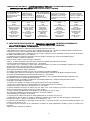 8
8
-
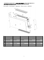 9
9
-
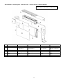 10
10
-
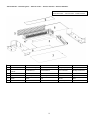 11
11
-
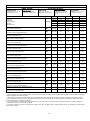 12
12
-
 13
13
-
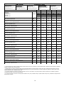 14
14
-
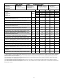 15
15
-
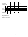 16
16
-
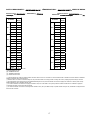 17
17
-
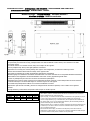 18
18
-
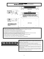 19
19
-
 20
20
-
 21
21
-
 22
22
-
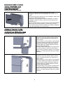 23
23
-
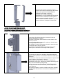 24
24
-
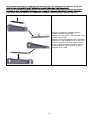 25
25
-
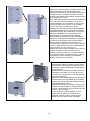 26
26
-
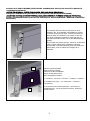 27
27
-
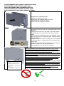 28
28
-
 29
29
-
 30
30
-
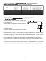 31
31
-
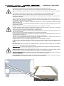 32
32
-
 33
33
-
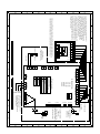 34
34
-
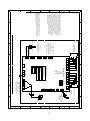 35
35
-
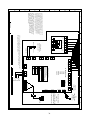 36
36
-
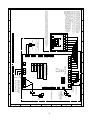 37
37
-
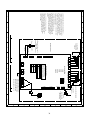 38
38
-
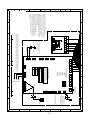 39
39
-
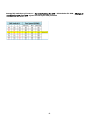 40
40
-
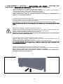 41
41
-
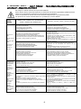 42
42
-
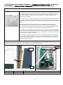 43
43
-
 44
44
-
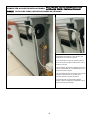 45
45
-
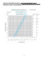 46
46
-
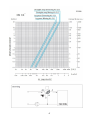 47
47
-
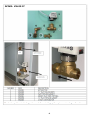 48
48
-
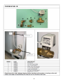 49
49
-
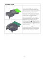 50
50
-
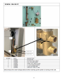 51
51
-
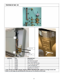 52
52
-
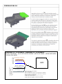 53
53
-
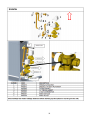 54
54
-
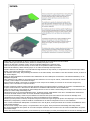 55
55
-
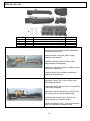 56
56
-
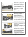 57
57
-
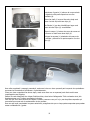 58
58
-
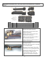 59
59
-
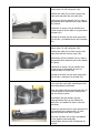 60
60
-
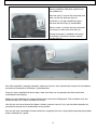 61
61
-
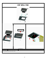 62
62
-
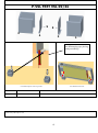 63
63
-
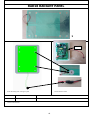 64
64
-
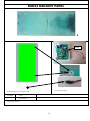 65
65
-
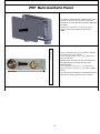 66
66
-
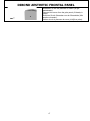 67
67
-
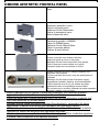 68
68
-
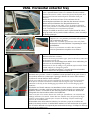 69
69
-
 70
70
-
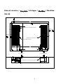 71
71
-
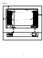 72
72
-
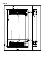 73
73
-
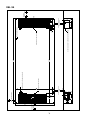 74
74
-
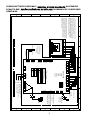 75
75
-
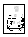 76
76
-
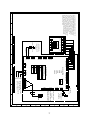 77
77
-
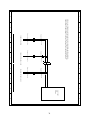 78
78
-
 79
79
-
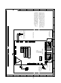 80
80
-
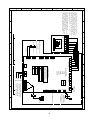 81
81
-
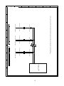 82
82
-
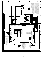 83
83
-
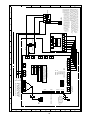 84
84
-
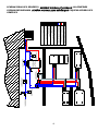 85
85
-
 86
86
-
 87
87


MAXA Grimper Fan El manual del propietario
- Tipo
- El manual del propietario
en otros idiomas
- français: MAXA Grimper Fan Le manuel du propriétaire
- italiano: MAXA Grimper Fan Manuale del proprietario
- English: MAXA Grimper Fan Owner's manual
- Deutsch: MAXA Grimper Fan Bedienungsanleitung
Otros documentos
-
Aermec VEC series Use And Installation Manual
-
Trane DFSL1 Manual de usuario
-
Kampmann Chilled water cassettes, article 325061* Guía de instalación
-
FläktGroup Cassette-Geko II EC Instrucciones de operación
-
-
Sabiana Skystar El manual del propietario
-
Trane BFSL 54 Technical Manual
-
-
Liebert Hisp Manual de usuario
-
Galletti FLAT S Installation, Use And Maintenance Manual