Galletti FLAT S Installation, Use And Maintenance Manual
- Tipo
- Installation, Use And Maintenance Manual

IT
EN
FR
DE
ES
PT
NL
HU
INSTALLAZIONE USO E MANUTENZIONE
INSTALLATION, USE AND MAINTENANCE
INSTALLATION, UTILISATION ET ENTRETIEN
INSTALLATION, BEDIENUNG UND WARTUNG
INSTALACIÓN, USO Y MANTENIMIENTO
INSTALAÇÃO, UTILIZAÇÃO E MANUTENÇÃO
INSTALLATIE, GEBRUIK EN ONDERHOUD
BESZERELÉS, HASZNÁLAT ÉS KARBANTARTÁS

2
FC66004073- 00
È severamente vietata la riproduzione anche parziale di questo manuale
FLAT S
IT
1 PRIMA DI INIZIARE L’INSTALLAZIONE
Leggere attentamente questo manuale .
L’installazione e la manutenzione dell’apparecchio devono essere effettuati
esclusivamente da personale tecnico qualificato per questo tipo di macchina,
in conformità con le normative vigenti.
Al ricevimento dell’apparecchio controllarne lo stato verificando che non
abbia subito danni dovuti al trasporto.
Per l’installazione e l’uso di eventuali accessori si rimanda alle relative schede
tecniche degli stessi.
Individuare il modello di ventilconvettore FLAT S dalle indicazioni riportate
sull’imballo.
2 UTILIZZO PREVISTO E LIMITI DI
FUNZIONAMENTO
La Galletti S.p.A. si ritiene sollevata da ogni responsabilità nei casi in cuil’ap-
parecchio sia installato da personale non qualificato, venga utilizzato impro-
priamente o in condizioni non ammesse, non venga effettuata manutenzione
prevista dal presente manuale o non siano stai utilizzati ricambi originali.
I limiti di funzionamento sono riportati di seguito; ogni altro uso è considerato
improprio:
- fluido termovettore: acqua
- temperatura acqua: da 5°C a 80°C
- massima pressione di esercizio: 10 bar
- temperatura aria: da 5°C a 43 °C
- tensione di alimentazione : 230V 50 Hz
Nella scelta del luogo di installazione osservare i seguenti punti:
- L’apparecchio di climatizzazione non deve essere posto immediatamente
sotto una presa di corrente.
- non installare l’unità in ambienti con presenza di gas o polveri infiammabili
- non esporre l’unità a spruzzi d’acqua
- installare il ventilconvettore su pareti o soffitti che ne reggano il peso mante-
nendo intorno uno spazio sufficiente a garantirne il buon funzionamento e
le operazioni di manutenzione
- Conservare l'unità nell’imballo fino al momento dell’installazione per evitare
infiltrazioni di polvere nel suo interno.
Leggere atten-
tamente
il manuale
Utilizzare dispositivi
di protezione indivi-
duale
ATTENZIONE
SIMBOLI DI SICUREZZA
DICHIARAZIONE DI CONFORMITÀ
La Galletti S.p.A. con sede in via Romagnoli 12/a, 40010
Bentivoglio (BO) - Italia, dichiara, sotto la propria responsabilità,
che i ventilconvettori FLAT S, apparecchi terminali per impianti
di riscaldamento e condizionamento dell'aria, sono conformi
a quanto prescritto dalle Direttive 2006/42/CE, 2004/108/CE,
2006/95/CE e successive modifiche.
Bologna li, 03/02/2016
Luca Galletti
Presidente
3 DESCRIZIONE DELL'APPARECCHIO
Ventilconvettori compatti di design con ventilatore centrifugo
FLAT S 2.8 kW
FLAT S Galletti: prestazioni e design in un unico terminale
FLAT S Galletti è stato progettato con l’obiettivo di offrire
prestazioni e design ai vertici della sua categoria.
L’unicità di FLAT S parte dall’utilizzo di materiali di altissima qualità che
contribuiscono alla eccezionale robustezza del prodotto, unitamente alla
garanzia di rendimenti costanti nel tempo. Le dimensioni compatte lo vendono
facilmente integrabile in ogni contesto.
FLAT S ottimizza la distribuzione dell’aria in ambiente grazie alla griglia di
uscita aria integrata che consente l’orientamento dell’aria trattata e filtrata
in 4 direzioni.
Il flap principale è dotato in un microinterruttore che interrompe il
funzionamento del ventilatore e manda in OFF le valvole in caso di chiusura.
Il flap è utile per evitare l’accumulo di polveri nei periodi di non utilizzo.
L’adozione di ABS stabilizzato agli UV nelle parti che compongono il mobile
di copertura e antistatico nel gruppo di ventilazione (coclea e ventilatore
centrifugo) garantiscono la medesima resa estetica e acustica
durante la vita del prodotto. Particolarmente curata la progettazione del gruppo
motoventilante che garantisce prestazioni sonore di assoluta eccellenza nella
motorizzazione a 3 velocità.
VERSIONI DISPONIBILI
* 4 tubi su richiesta
PLUS
- Mobile di design
- Utilizzo di ABS stabilizzato ai raggi UV
- Attacchi idraulici reversibili
- Motore a 3 velocità
- Ventilatori centrifughi in ABS
- Integrabile ad ERGO
- Ionizzatore incorporabile
2
Super-
visione
ERGO
Impianto
a 2 tubi*
Instal-
lazione
verticale
Venti-
latore
centrifugo
FLAT S
Installazione in vista sospeso
a parete, mobile di copertura
con uscita aria verticale.
VERSIONS
FLS 1 XX
VARIANTS
SIZES 10÷40

FC66004073- 00
È severamente vietata la riproduzione anche parziale di questo manuale
FLAT S
3
IT
COMPONENTI PRINCIPALI
Mobile di copertura
Ventilatori
Struttura
Motore elettrico
Batteria di scambio
termico
Colore RAL9010, pannello frontale
in lamiera di acciaio. Fiancate,
griglia superiore e portelle laterali
realizzate in ABS stabilizzato agli UV
per mantenere il colore inalterato nel
tempo. La griglia superiore è costi-
tuita da un flap ed alette orientabili.
Il flap è dotato di microinterruttore
che interrompe il funzionamento
dell’unità quando viene posto in
posizione di chiusura.
Centrifughi a doppia aspirazione,
bilanciati staticamente e dinami-
camente, sono realizzati in ABS
antistatico con pale a profilo
alare e moduli sfalsati. I ventilatori
sono alloggiati in una coclea in
ABS ad alta efficienza.
Realizzata in lamiera di acciaio
zincato di elevato spessore, isola-
ta termicamente ed acusticamen-
te con pannelli autoestinguenti di
classe 1.
Montato su supporti antivibranti, con condensatore permanentemente
inserito e protezione termica degli avvolgimenti è direttamente accoppiato
ai ventilatori. È disponibile a 3 velocità di rotazione per rispondere a tutte le
richieste specifiche di prestazioni, silenziosità, consumi elettrici.
Ad alta efficienza in tubo di rame
ed alette in alluminio, è corredata
di collettori in ottone e valvola di
sfiato. Gli attacchi idraulici sono
reversibili in fase di installazione.
Su richiesta è possibile montare
una batteria addizionale, per im-
pianti a 4 tubi.
Filtro aria
Filtro rigenerabile realizzato in
polipropilene a nido d’ape, facil-
mente estraibile per le operazioni
di manutenzione.
ACCESSORI
Pannelli di comando elettromeccanici
TIB
Comando elettromeccanico completo di commutatore di velocità,
termostato e selettore stagionale
TC
Termostato elettromeccanico di minima temperatura acqua in
riscaldamento, montaggio sulla batteria
CD Commutatore di velocità ad incasso a parete
CDE Commutatore di velocità a parete
TD
Comando a parete elettromeccanico completo di commutatore di
velocità, termostato e selettore stagionale
TDC
Comando a parete elettromeccanico completo di commutatore di
velocità, termostato
TD4T
Comando a parete elettromeccanico con commutatore di
velocità, termostato e selettore stagionale per il controllo del
ventilconvettore e valvole ON/OFF
Pannelli di comando elettronici a microprocessore
MCBE MYCOMFORT BASE comando elettronico con display
MCME MYCOMFORT MEDIUM comando elettronico con display
MCLE MYCOMFORT LARGE comando elettronico con display
EVO Comando a microprocessore a parete e a bordo
KBFLAE
KIT installazione a bordo FLAT
MCSWE
Sonda acqua per comandi a microprocessore MYCOMFORT
BASE, MEDIUM, LARGE, e EVO
MCSUE
Sonda umidità remota per comandi a EVO, MYCOMFORT MEDIUM
E LARGE installati a bordo macchina
Interfaccia di potenza
KP
Interfaccia di potenza per il collegamento in parallelo fino a 4
ventilconvettori ad un unico comando
Batteria addizionale per impianti a 4 tubi
DFS
Batteria addizionale ad 1 rango per impianti a 4 tubi (circuito
acqua calda)
Zoccoli di sostegno e pannelli di chiusura
ZLS Coppia di zoccoli di sostegno e copertura
PVS
Pannello posteriore preverniciato per ventilconvettori ad
installazione verticale con mobile
Valvole
VKS
Valvola a 2 o 3 vie con motore elettro-termico ON/OFF o
modulante e kit idraulico di montaggio per batteria standard
VKDFS
Valvola a 2 o 3 vie con motore elettro-termico ON/OFF o
modulante e kit idraulico di montaggio per batteria DF
Bacinelle ausiliarie di raccolta condensa, gusci isolanti
BV
Bacinella ausiliaria di raccolta condensa per ventilconvettori ad
installazione verticale
GIVKS Guscio coibentazione valvola

4
FC66004073- 00
È severamente vietata la riproduzione anche parziale di questo manuale
FLAT S
IT
per evitare infiltrazioni di polvere nel suo interno.
5 INSTALLAZIONE
FLAT S installazione a parete (100 mm dal pavimento)
AVVERTENZE PER L'INSTALLAZIONE
I ventilconvettori vanno installati in una posizione tale da riscaldare e raffrescare
uniformemente il locale, su pareti o soffitti che ne reggano il peso.
Installare gli eventuali accessori sull’apparecchio standard prima di procedere
alla sua installazione.
Per l'installazione e l'uso di eventuali accessori si rimanda alle relative schede
tecniche.
Mantenere intorno al ventilconvettore lo spazio necessario a consentirne
il corretto funzionamento e tale da permettere di effettuare operazioni di
manutenzione ordinaria e straordinaria (figura 1).
Installare l'eventuale pannello di comando a distanza in una posizione facil-
mente raggiungibile dall'utente per l'impostazione delle funzioni e, se prevista,
efficace per la rilevazione della temperatura. Evitare quindi:
- posizioni esposte direttamente all’irraggiamento solare;
- posizioni soggette a correnti dirette di aria calda o fredda;
- di interporre ostacoli che impediscano la rilevazione corretta della temperatura.
Nel caso di fermate invernali scaricare l’acqua dall’impianto onde evitare
danneggiamenti dovuti a formazione di ghiaccio; se vengono utilizzate
soluzioni antigelo verificare il punto di congelamento utilizzando la tabella
a riportata di seguito.
% glicole temperatura Variazione Variazione
in peso congelamento (°C) potenza resa perdita di carico
0 0 1,00 1,00
10 -4 0,97 1,05
20 -10 0,92 1,10
30 -16 0,87 1.15
40 -24 0,82 1,20
Procedere all'installazione dell’unità base alla parete utilizzando le 4 asole
predisposte, con tasselli adeguati alle caratteristiche della parete di ancoraggio,
mantenendo il filo inferiore a 100 mm dal pavimento per una corretta aspirazione
dell’aria ed un’agevole estrazione del filtro per la versione FLAT S (fig.1).
Gli attacchi idraulici sono previsti di serie sul lato sinistro, guardando
frontalmente l'apparecchio.
E’ possibile orientare gli attacchi dello scambiatore sul lato opposto operando
come segue (figura 5):
- smontare il mobile di copertura (figura 4);
- smontare il convogliatore anteriore (6 viti)
- smontare la batteria di scambio t ermico (4 viti) fissata alle fiancate dell’unità
base;
- rimuovere il setto inferiore;
- scollegare i cavi motore dalla morsettiera
- smontare la morsettiera rimontandola sulla fiancata opposta
- sfilare il cavo motore orientandolo sul lato opposto; togliere il passacavo
in plastica;
- togliere il tubo di scarico condensa e rimontarlo sul lato opposto; invertire
la posizione del tubo rompi-goccia e del tappo di chiusura sulla vasca di
raccolta condensa;
- ruotare la batteria di 180°;
- rimontare il setto sul lato inferiore;
- inserire gli attacchi nelle apposite aperture sulla fiancata DX; fissarla quindi
all’unità base con le relative viti;
- inserire il passacavo in plastica nel foro prima occupato dal tubo di scarico
condensa, rimontare il fermacavo sulla fiancata, inserire i cavi e collegarli
alla morsettiera.
- rimontare il convogliatore anteriore (6 viti)
- chiudere i fori non più utilizzati con materiale anticondensa.
Nella figura 1 è riportato il disegno esploso di FLAT S, dove:
1. Unità base
2. Scambiatore di calore
3. Motore elettrico
4. Ventilatore centrifugo (coclea e ventola in ABS)
5. Vasca raccolta condensa
6. Convogliatore
7. Filtro
8. Mobile di copertura
9. Cavo di collegamento microinterruttore
10. Morsettiera collegamento e fermacavo
11. Pannello di comando (accessorio)
12. Viti di fissaggio del mobile
13. Flap superiore
14. Alette orientabili
4 DATI DIMENSIONALI
Nella figura 2 sono riportati i dati dimensiona li di FLAT S, in figura 3 sono
riportate le posizioni degli attacchi idraulici della batteria addizionale disponibile
a richiesta per impianti a 4 tubi, dove:
- Diametro attacchi idraulici per la batteria standard = 1/2" femmina gas
- Diametro scarico condensa Ø 16 mm
5 INSTALLAZIONE
ATTENZIONE: l’installazione e l’avviamento dell’unità devono essere effet-
tuati da personale competente, secondo le regole della corretta pratica
impiantistica, in conformità alle normative vigenti.
Per ogni unità, prevedere sulla rete di alimentazione un interruttore (IL)
con contatti di apertura con distanza di almeno 3 mm e un fusibile (F) di
protezione adeguato.
ATTENZIONE : Installare l'unità , l’interruttore di linea (IL), e/o gli eventuali
comandi a distanza in una posizione non raggiungibile da persone che si
trovino nella vasca da bagno o nella doccia.
Rimuovere il mobile di copertura , agendo sulle viti di fissaggio accessibili
a portelle sollevate (figura 4).
Attenzione: il cavo di collegamento del microinterruttore è cablato alla
morsettiera di appoggio e deve essere scollegato prima di allontanare
completamente il mobile di copertura dalla unità base.
Nella scelta del luogo di installazione osservare i seguenti punti:
- L’apparecchio di riscaldamento non deve essere posto immediatamente
sotto una presa di corrente.
- non installare l’unità in ambienti con presenza di gas o polveri infiammabili
- non esporre l’unità a spruzzi d’acqua.
- installare il terminale su pareti che ne reggano il peso, mantenendo intorno
uno spazio sufficiente a garantirne il buon funzionamento e le operazioni
di manutenzione (figura 1).
- Conservare il terminale nell’imballo fino al momento dell’installazione

FC66004073- 00
È severamente vietata la riproduzione anche parziale di questo manuale
FLAT S
5
IT
NOTA: i cablaggi elettrici devono essere sempre posizionati sul lato
opposto agli attacchi idraulici.
Realizzare i collegamenti idraulici alla batteria di scambio termico e, nel caso
di funzionamento in fase di raffreddamento, allo scarico condensa.
E’ consigliabile prevedere la mandata dell’impianto nella parte bassa dello
scambiatore di calore ed il ritorno nella parte alta dello stesso.
Effettuare lo sfogo dell’aria dallo scambiatore agendo sulle valvole di sfiato
(chiave di 10 esag.) poste a fianco degli attacchi idraulici della batteria stessa.
Per favorire il drenaggio della condensa inclinare la tubazione di scarico
verso il basso di almeno 3 cm/m; sul suo percorso non si devono formare
anse o strozzature.
COLLEGAMENTI ELETTRICI
Effettuare i collegamenti elettrici in assenza di tensione, secondo le
normative di sicurezza vigenti, seguendo scrupolosamente lo schema di
figura 6 e relativa legenda.
Verificare che la tensione di rete corrisponda a quella indicata sulla targhetta
dell’apparecchio.
I collegamenti elettrici tratteggiati vanno eseguiti dall’installatore.
Per ogni ventilconvettore prevedere sulla rete di alimentazione un interruttore
(IL) con contatti di apertura con distanza di almeno 3mm e un fusibile (F)
di protezione adeguato.
Negli schemi elettrici sono utilizzate le seguenti abbreviazioni:
1 Collegamento al pannello di comando (accessorio)
BK Nero = Velocità alta
BN Marrone
BU Blu = Velocità media
C Commutatore di velocità
CN Connettore a fast-on
F Fusibile di protezione non fornito
IL Interruttore di linea, non fornito
M Motore
MS Microinterruttore FLAP uscita aria
RD Rosso = Velocità minima
SF Selettore di funzionamento
T Termostato
TC Termostato di consenso (accessorio
WH Bianco = comune
S Selettore ON-OFF
VK C Valvola a 3 vie motorizzata ON-OFF
(accessorio) batteria raffreddamento
VK H Valvola a 3 vie motorizzata ON-OFF
(accessorio) batteria riscaldamento
Ad installazione ultimata, prima di installare il mobile sull'unità base, collegare
il cavo del microinterruttore alla morsettiera di appoggio.
Al termine dell'installazione installare il filtro aria sull'aspirazione e
fissarlo utilizzando la vite centrale a corredo (dotarsi di cacciavite
a croce, lunghezza massima 8 cm).
6 VERIFICA FUNZIONALE
- Verificare che l’apparecchio sia perfettamente livellato e che lo scarico
condensa non sia ostruito (depositi di calcinacci ecc.).
- Verificare che l’apparecchio sia installato in modo da garantire il corretto
flusso d’aria.
- Controllare la tenuta dei collegamenti idraulici (allo scambiatore e allo
scarico condensa).
7 USO
Per l'utilizzo del ventilconvettore riferirsi alle istruzioni del pannello di comando,
disponibile come accessorio.
L’orientazione del flusso d’aria è possibile utilizzando il FLAP superiore
(controllo del flusso verso l’alto o verso il basso) ed anche il secondo ordine
di alette (per indirizzare l’aria a destra o sinistra rispetto alla verticale) come
riportato in Figura 7.
Il FLAP superiore può essere utuilizzato anche per avviare ed interrompere
il funzionamento dell'unità: la chiusura corrisponde all'interruzione del
funzionamento del ventilatore ed eventualmente della valvola di regolazione
(vedere schemi elettrici pannelli di comando disponibili in opzione) Figura 8.
Per evitare comunque l'ingresso di polvere all'interno dell'apparecchio, porre
sempre il FLAP il posizione di chiusura nei periodi di non utilizzo.
Per motivi di sicurezza, non introdurre mani o oggetti nella griglia di
uscita dell'aria.
8 MANUTENZIONE
Per motivi di sicurezza, prima di compiere qualsiasi manutenzione o
pulizia, spegnere l’apparecchio ponendo il commutatore di velocità su
“Arresto” e l’interruttore di linea su 0 (OFF).
Prestare attenzione durante le operazioni di manutenzione: alcune parti
metalliche possono provocare ferite: dotarsi di guanti protettivi.
I ventilconvettori FLAT S non necessitano di particolari manutenzioni: è
sufficiente la pulizia periodica del filtro aria.
E’ necessario un periodo di rodaggio di 100 ore di funzionamento per eliminare
tutti gli attriti meccanici iniziali del motore.
Effettuare il primo avviamento alla velocità massima di funzionamento.
Per garantire il buon funzionamento dei ventilconvettori FLAT S
osservare le indicazioni riportate di seguito:
- mantenere il filtro aria pulito;
- non versare liquidi all’interno dell’apparecchio;
- non introdurre parti metalliche attraverso la griglia di uscita aria;
- evitare di ostruire la mandata o l’aspirazione dell’aria.
Ad ogni avviamento seguente una lunga sosta assicurarsi che non sia presente
aria all’interno dello scambiatore di calore.
Prima del periodo di funzionamento in fase di raffrescamento verificare
che lo scarico della condensa avvenga correttamente e che le alette dello
scambiatore di calore non siano ostruite da impurità.
Procedere eventualmente alla loro pulizia con aria compressa o con vapore
a bassa pressione, senza danneggiare le alette.
Una manutenzione adeguata e periodica si traduce in risparmio energetico
ed economico.
- Controllare che i cablaggi elettrici siano ben saldi (eseguire il controllo
in assenza di tensione).
- Assicurarsi che sia stata eliminata l’aria dallo scambiatore di calore.
- Rimontare il mobile di copertura.
- Dare tensione al ventilconvettore e verificarne il funzionamento.

6
FC66004073- 00
È severamente vietata la riproduzione anche parziale di questo manuale
FLAT S
PROBLEMA
CAUSA SOLUZIONE
L'unità non funziona
1 Manca corrente
2 E’ scattato il salvavita
3 L'interruttore di avviamento è posto su 0.
4 FLAP chiuso
1 Ridare corrente
2 Chiedere l’intervento del servizio assistenza
3 Avviare la macchina ponendo l'interruttore su I
4 Aprire il FLAP
L'unità riscalda o raffresca poco
1 Il filtro aria è sporco o otturato
2 Lo scambiatore di calore è sporco
3 C’e un ostacolo vicino all’aspirazione o all’uscita
dell’aria
4 E’ presente dell’aria all’interno dello scambiatore di
calore
5 Le finestre e le porte sono aperte
6 E’ selezionata la velocità minima di funzionamento
1 Pulire Il filtro aria
2 Chiedere l’intervento dell’installatore
3 Rimuovere l’ostacolo
4 Chiedere l’intervento dell’installatore
5 Chiudere porte e/o finestre
6 Selezionare la velocità media o massima
L'unità “perde” acqua
1 L’apparecchio non è installato con la giusta
inclinazione
2 Lo scarico condensa è ostruito
1 Chiedere l’intervento dell’installatore
2 Chiedere l’intervento dell’installatore
IT
9 RICERCA DEI GUASTI
Se l’apparecchio non funziona correttamente, prima di richiedere l’intervento del servizio assistenza, eseguite i controlli riportati nella tabella sotto riportata.
Se il problema non può essere risolto, rivolgetevi al rivenditore o al centro assistenza più vicino.
PULIZIA DEL FILTRO ARIA
Pulire il filtro aria almeno una volta al mese e prima di ogni periodo di
utilizzo (prima del periodo di riscaldamento e del periodo di condiziona-
mento).
Per la pulizia del filtro aria procedere nel seguente modo (figura 9):
1. Svitare la vite centrale che blocca il filtro sulla guida ed liberarlo
dall’appoggio facendo basculare verso l’alto la parte di filtro rivolta verso
la parete sulla quale è installato il terminale.
2. Estrarre il filtro e pulirlo con acqua tiepida (nel caso di polveri secche,
con aria compressa)
3. Dopo averlo lasciato asciugare, reinserire il filtro tenendolo inclinato
verso il basso nella parte frontale.
4. Una volta che il filtro sia ritornato in appoggio sulle fiancate dell'unità
base e sia stato inserito nella guida frontale, riavvitare la vite centrale per
bloccarlo ed impedire l’accesso al ventilatore.
ATTENZIONE: IL FILTRO ARIA DEVE SEMPRE ESSERE BLOCCATO
MEDIANTE L’APPOSITA VITE AFFINCHÈ SIA IMPEDITO IL CONTATTO
ACCIDENTALE CON IL VENTILATORE.
Si consiglia la sostituzione annuale del filtro aria, utilizzando ricambi origi-
nali; il modello di terminale è individuabile sulla targhetta di identificazione
posta sulla fiancata interna.
PULIZIA DELLA BATTERIA DI SCAMBIO TERMICO
E’ consigliabile controllare lo stato degli scambiatore prima di ogni periodo
di funzionamento, verificando che le alette non siano ostruite dall’impurità.
PULIZIA DELLA MOBILE DI COPERTURA
- Utilizzate un panno morbido.
- Non versare mai liquidi sull’apparecchio, perché si potrebbero provocare
scariche elettriche e danneggiare le parti interne.
- Non utilizzare mai solventi chimici aggressivi; non pulire il flap di uscita
dell’aria con acqua molto calda.
Questo apparecchio non è previsto per essere utilizzato da bambini o da
persone con problemi fisici, sensoriali o mentali, inesperte o impreparate,
in mancanza di supervisione.
Fare attenzione affinché i bambini non abbiano accesso all'apparecchio.

FC66004073- 00
È severamente vietata la riproduzione anche parziale di questo manuale
FLAT S
7
IT
FLAT S 10 20 30 40
Velocità
3x min med Max min med Max min med Max min med Max
6x n° 1 2 3 1 2 3 1 2 3 1 2 3
Portata aria m3/h 115 135 170 135 170 225 200 250 340 250 310 420
Alimentazione elettrica 230-1-50 230-1-50 230-1-50 230-1-50
Potenza assorbita (E) W 12 17 23 14 20 27 23 28 37 25 31 42
Corrente assorbita massima A 0,06 0,09 0,12 0,07 0,11 0,14 0,12 0,15 0,20 0,13 0,17 0,22
Resa rareddamento totale (1) kW 0,86 0,98 1,24 1,09 1,34 1,75 1,41 1,76 2,32 1,76 2,14 2,78
Resa rareddamento sensibile (1) kW 0,61 0,7 0,89 0,75 0,93 1,22 1,02 1,27 1,69 1,27 1,55 2,03
Resa rareddamento totale (5) (E) kW 0,85 0,96 1,22 1,08 1,32 1,72 1,39 1,73 2,28 1,74 2,11 2,74
Resa rareddamento sensibile (5) (E) kW 0,60 0,68 0,87 0,74 0,91 1,19 1 1,24 1,65 1,25 1,52 1,99
Portata acqua rareddamento (1) l/h 148 168 213 186 230 300 243 303 399 303 368 477
Perdita di carico rareddamento (1) (E) kPa 3 3 5 5 7 11 3 5 7 5 6 10
FCEER (E) D D D D
Resa riscaldamento (2) (E) kW 1,07 1,21 1,52 1,21 1,47 1,93 1,81 2,21 2,88 2,21 2,66 3,42
Perdita di carico (2) (E) kPa 2 3 4 4 6 9 3 4 6 4 5 8
Resa riscaldamento (3) kW 1,8 2,05 2,57 2,02 2,45 3,21 3,07 3,73 4,84 3,73 4,48 5,76
Portata acqua (3) l/h 158 180 225 177 215 282 269 327 425 327 394 505
Perdita di carico (3) kPa 2 3 4 3 5 7 3 4 6 4 6 9
FCCOP (E) C C C C
Potenza sonora (4) (E) dB/A 30 35 40 35 40 46 32 38 46 37 42 49
Pressione sonora (6) dB/A 8 13 18 13 18 24 10 16 24 15 20 27
Numero ventilatori nr. 1 1 2 2
Attacchi idraulici std “ 1 / 2 1 / 2 1 / 2 1 / 2
Contenuto acqua std dm3 0,81 1,11 1,41 1,41
Peso kg 17,0 21,0 22,8 22,8
10 DATI TECNICI NOMINALI
1 ACQUA 7/12 °C, ARIA 27°C-19°C
2 ACQUA 50 °C, STESSA PORTATA DEL RAFFREDDAMENTO, ARIA 20°C
3 ACQUA 70/60, ARIA 20°C
4 Potenza sonora rilevata secondo ISO3741 e ISO3742
5 Espressa secondo EN1397
6 Calcolata con Q=2 e distanza 5 metri dalla sorgente in campo libero
E Dati certificati EUROVENT
VERSIONI 4 TUBI DISPONIBILI SU RICHIESTA

8
FC66004073- 00
È severamente vietata la riproduzione anche parziale di questo manuale
FLAT S
IT
CONDIZIONI GENERALI DI GARANZIA
UNITÀ FLAT GALLETTI
1) Le unità FLAT Galletti S.p.A., sono garantiti per 24 mesi dalla data di consegna all’utilizzatore. La garanzia è relativa alla riparazione e/o sostituzione in forma
gratuita dei componenti con “vizi” o difetti di fabbricazione.
2) Galletti vincola la concessione della garanzia alla verifica di vizi o difetti dei componenti, attraverso un Centro Assistenza Autorizzato dalla scrivente stessa sul
territorio di competenza.
3) In conformità con la direttiva 199/44/CE attuata dal Decreto Legislativo N.24 (2 Febbraio 2002), la garanzia Galletti è applicabile esclusivamente al prodotto non
contemplando alcuna parte dell’impianto.
4) La data di decorrenza della garanzia sarà relativa al documento fiscale di accompagnamento. In mancanza dello stesso la Galletti si riserva di stabilire la decorrenza
dalla data di fabbricazione.
5) Scaduti i termini di garanzia, i costi relativi ai ricambi ed alla manodopera necessaria per la riparazione, sono a carico del cliente.
6) Come specificato dai termini di legge (DL 199), l’obbligo della garanzia all’utilizzatore finale è a carico del venditore (la società presso la quale ha effettuato l’acquisto).
Galletti attiverà le procedure di garanzia su richiesta del venditore.
7) La garanzia Galletti non copre:
- Controlli, manutenzioni, riparazioni dovuti a normale usura
- Installazione errata o non conforme
- Danni da trasporto e/o movimentazione non reclamati all’atto della consegna
- Uso improprio
- Alimentazione elettrica non “prevista” dai dati di targa
- Danni o manipolazioni di personale non autorizzato
- Atti vandalici e danni da agenti atmosferici.
8) Galletti si riserva di contestare la validità della garanzia se, da riscontri oggettivi, risulti che il prodotto abbia funzionato prima della decorrenza della garanzia.
9) Le modalità delle presenti condizioni di garanzia sono valide ed applicabili esclusivamente per il territorio italiano.
ONLY FOR ITALIAN MARKET
SEULEMENT POUR LE MARCHÉ ITALIEN
NUR FÜR DEN ITALIENISCHEN MARKT
IT

FLAT S
All copying, even partial, of this manual is strictly forbidden
FC66004073- 00
9
1 BEFORE STARTING THE INSTALLATION
PROCEDURE
Carefully read this manual.
Installation and maintenance may be carried out solely by qualified techni-
cians specifically trained for this type of equipment, in conformity with
current regulations.
On receiving the equipment, check that it has not undergone any damage
during transport.
For installation and use of accessories, please refer to the relative technical
sheets.
Identify the model of the FLAT S fan coil following the indications on the
packing container.
2 INTENDED USE AND OPERATING LIMITS
Galletti S.p.A. will not accept any liability for damage or injury caused as a
result of installation by non-qualified personnel; improper use or use in condi-
tions not allowed by the manufacturer; failure to perform the maintenance
prescribed in this manual; use of spare parts other than original factory parts.
The operating limits are specified below; usage outside the stated limits is
to be considered improper:
- thermal carrier fluid: water
- water temperature: from 5°C to 80°C
- maximum water pressure during operation: 10 bar
- air temperature: from 5°C to 43 °C
- supply voltage: 230 V 50 Hz
When choosing an installation site, you should observe the following rules:
- The air conditioning unit should not be placed immediately under a socket
- Do not install the unit in places where inflammable gases or powders are
present
- Do not expose the unit to sprays of water
- Install the fan coil on walls or ceilings able to withstand its weight. Keep
a clear space all around the unit to assure the proper functioning and ac-
cessibility for maintenance
- Store the unit in its packing container until you are ready to install it to
prevent dust from infiltrating inside it.
Carefully read
this manual
Use individual pro-
tective devices
WARNING
SAFETY SYMBOLS
DECLARATION OF CONFORMITY
Galletti S.p.A., whose main office is in via Romagnoli 12/a,
40010 Bentivoglio (Bologna) - Italy, hereby declares, under its
sole responsibility, that the FLAT fan coil, indoor units for heating
and air conditioning systems, conform to the specifications of
the Directives 2006/42/EC, 2004/108/EC, 2006/95/EC and
subsequent amendments.
Bologna, 03.02.2016
Luca Galletti
President
3 UNIT DESCRIPTION
Compact design fan coils with centrifugal fan
FLAT S 2.8 kW
Galletti FLAT S: performance and design in a single indoor unit
FLAT S by Galletti has been engineered to offer performance and design
features placing it at the top of its category.
The uniqueness of FLAT S lies both in the use of extremely high quality
materials - which contribute to making this product exceptionally robust - and
the assurance of constant performance over time. The compact dimensions
make it particularly easy to be integrated in any context.
FLAT S optimizes the distribution of air in the room thanks to the integrated
air outlet grille which makes it possible to direct the treated, filtered air in 4
directions.
The main flap is equipped with a microswitch which shuts off the fan and
the valves when the flap closes. The flap is useful for avoiding dust build-up
in periods of non-use.
The adoption of UV-stabilized ABS in the parts making up the cabinet and
antistatic ABS in the fan assembly (volute and centrifugal fan) guarantee that
the product will maintain the same aesthetics and noise levels throughout
its lifetime. Particular care has been taken in the design of the fan drive
assembly, which guarantees exceptionally quiet operation in the version
with 3-speed motors.
AVAILABLE VERSIONS
* 4 pipes on request
PLUS
- Cabinet with a refined design
- Use of UV-stabilized ABS
- Reversible water connections
- 3-speed motor
- ABS centrifugal fans
- Can be integrated into ERGO
- Incorporable ioniser
2
ERGO
Supervi-
sion
2-pipe
systems*
Vertical
installa-
tion
Centrifu-
gal fan
FLAT S
Suspended wall installation,
with cabinet, with vertical air
flow.
VERSIONS
FLS 1 XX
VARIANTS
SIZES 10÷40
EN

FC66004073- 00
FLAT S
All copying, even partial, of this manual is strictly forbidden
10
FC66004073- 00
MAIN COMPONENTS
Cabinet
Fans
Structure
Electric motor
Heat exchanger
RAL9010 colour, front panel made
of sheet steel. Side panels and
an upper grille with covers on
either side manufactured from
UV-stabilised ABS to maintain
the colour intact over time. The
upper grille consists of a flap and
adjustable louvers. The flap features
a microswitch that automatically
shuts down the unit when the flap
itself is closed.
Double suction centrifugal
fans, statically and dynamically
balanced, manufactured from
anti-static ABS, with blades
having an airfoil section and
offset modules. The fans are
housed in a low-noise ABS volute
with high-efficiency profile.
Built from galvanised steel sheet
of extra thickness, heat and
sound insulated by means of
Class 1 self-extinguishing panels.
It is mounted on vibration dampers, with permanently activated capacitor
and thermal protection of the windings, and is directly coupled with the fans.
It is available as 3-speed version in order to meet all the specific needs of
performance, quietness, and power consumption.
High efficiency heat exchanger
made with copper piping and
aluminium fins, provided with
brass manifolds and vent
valve. The water connections
are reversible at the time of
installation. On request it is
possible to mount an additional
heat exchanger for 4-pipe
systems.
Air lter
Honey-comb polypropylene
washable air filter, easily
removable for maintenance
operations.
ACCESSORIES
Electromechanical control panels
TIB
Electromechanical controller, complete with speed selector,
thermostat and summer/winter selecting switch
TC
Electromechanical thermostat for minimum water temperature in
heating mode, mounted on the heat exchanger
CD Recess wall-mounted speed selector
CDE Wall-mounted speed selector
TD
Wall-mounted electromechanical controller, complete with speed
selector, thermostat and summer/winter selecting switch.
TDC
Wall-mounted electromechanical controller, complete with speed
selector and thermostat.
TD4T
Wall-mounted electromechanical controller, complete with speed
selector, thermostat and summer/winter selecting switch for
control of the fan coil and ON/OFF valves.
Wall-mounted microprocessor electronic control panels
MCBE MYCOMFORT BASE electronic controller with display
MCME MYCOMFORT MEDIUM electronic controller with display
MCLE MYCOMFORT LARGE electronic controller with display
EVO Wall-mounted and on-board mounted microprocessor controller
KBFLAE FLAT on-board installation kit
MCSWE
Water probe for microprocessor controls model MYCOMFORT
BASE, MEDIUM, LARGE and EVO
MCSUE
Remote humidity sensor for EVO, MYCOMFORT MEDIUM and
LARGE on-board controllers
Power interface
KP
Power interface for connecting in parallel up to 4 fan coils to one
controller
Additional heat exchanger for 4-pipe systems
DFS
1 row additional heat exchanger for 4-pipe systems (hot water
circuit)
Base supports and enclosing panels
ZLS Pair of base and enclosure elements
PVS
Rear pre-painted panel for vertical installation fan coils with
cabinet
Valves
VKS
2 or 3-way valve with ON/OFF or modulating electrothermal motor
and hydraulic kit for standard heat exchanger
VKDFS
2 or 3-way valve with ON/OFF or modulating electrothermal motor
and hydraulic kit for DF heat exchanger
Auxiliary water drip trays, insulating shell
BV
Auxiliary water drip tray for vertical installation fan coil units
GIVKS Valve insulation shell
EN

FLAT S
All copying, even partial, of this manual is strictly forbidden
FC66004073- 00
11
5 INSTALLATION
FLAT S wall installation (100 mm from floor)
INSTALLATION REQUIREMENTS
The fan coils should be installed in a position where the room can be cooled
or heated evenly, on walls or ceilings able to withstand their weight.
It is advisable to install any accessories on the standard unit prior to
positioning the latter.
For installation and use of accessories, please refer to the relative technical
sheets.
To guarantee the proper functioning of the unit and access for routine and
extraordinary maintenance purposes, it is necessary to comply with the
minimum installation clearance requirements (figure 1).
Install any remote control panel in an easily accessible position allowing the
user to set the functions while ensuring an accurate reading of the ambient
temperature, if provided . You should avoid:
- positions directly exposed to sunlight;
- positions exposed to direct currents of warm or cold air;
- placing obstacles that impede an accurate temperature reading.
During wintertime periods of quiescence, drain water from the system, to
prevent ice from forming. If anti-freeze solutions are used, check for their
freezing point using the table below.
Glycol by weight
(%)
Freezing
temperature (°C)
Capacity
adjustment
Pressure drop
adjustment
0 0 1.00 1.00
10 -4 0.97 1.05
20 -10 0.92 1.10
30 -16 0.87 1.15
40 -24 0.82 1.20
Fasten the base unit to the wall using the 4 slots provided and the screw
anchors suitable for the characteristics of the supporting wall, keeping the
bottom edge at least 100 mm above the floor to ensure a correct intake of air
and facilitate the filter removal in the case of FLAT S model (fig. 1).
The water connections are on the left side, viewing the unit from the front.
The exchanger connections can be switched over to the opposite side by
carrying out the following steps (figure 5):
- remove the cabinet (figure 4)
- remove front duct (6 screws)
- remove the heat exchanger (4 screws) mounted on the base unit side panels
- remove the lower partition
- disconnect the motor cables from the terminal board
- remove the terminal board and mount it on the opposite side panel
- pull the motor cable and guide it to the opposite side; remove the plastic
cable bushing
- detach the condensate drainage hose and reattach it on the opposite side;
switch over the position of the drop-stop hose and the cap on the drip tray;
- turn the heat exchanger by 180°
- replace the partition on the bottom part
- insert the connections in the proper slots on the right side panel; fasten
them to the base unit with proper screws
- insert the plastic cable bushing in the hole that was previously occupied
by condensate drainage hose, replace the cable holder on the side panel,
insert the cables and connect them to the terminal board
- replace front duct (6 screws)
- stop the unused holes with condensate proof material.
NOTE: the electrical wiring must always be positioned on the opposite
side of the plumbing connections.
Figure 1 shows the exploded view of FLAT S where:
1. Basic unit
2. Heat exchanger
3. Electric motor
4. Centrifugal fan (ABS volute and fan)
5. Water drip tray
6. Conveyor
7. Filter
8. Cabinet
9. Cable connecting to the microswitch
10. Connection terminal board and cable holder
11. Control panel (accessory)
12. Cabinet fastening screws
13. Upper flap
14. Adjustable fins
4 DIMENSIONS
Figure 2 shows the dimensions of FLAT S and figure 3 shows the position of
water connections of the additional heat exchanger available as accessory
for 4 pipe installations where:
- Diameter of water connections for standard heat exchanger = 1/2"
female gas
- Drain outlet Ø 16 mm
5 INSTALLATION
WARNING: unit installation and start-up must be entrusted to competent
personnel and performed in a workmanlike manner, in accordance with
current regulations.
For each unit an (IL) switch should be mounted on the power supply, with
opening contacts at a distance of at least 3 mm and a suitable protection
fuse (F) .
WARNING: Install the unit, circuit breaker (IL) and/or any remote controls
in a place out of reach of persons who may be taking a bath or shower.
Remove the cabinet by taking out the fastening screws, accessible once
the doors have been lifted (figure 4).
WARNING: the cable connecting the microswitch is wired to the terminal
block and must be disconnected before the cabinet can be completely
disengaged from the base unit
When choosing an installation site, you should observe the following rules:
- The heating unit should not be placed immediately under a socket.
- Do not install the unit in places where inflammable gases or powders are
present;
- Do not expose the unit to sprays of water;
- Install the unit on walls able to withstand its weight. Keep a clear space
all around the unit to assure the proper functioning and accessibility for
maintenance;
- Store the unit in its packing container until you are ready to install it to
prevent dust from infiltrating inside it.
EN

FC66004073- 00
FLAT S
All copying, even partial, of this manual is strictly forbidden
12
FC66004073- 00
Make the plumbing connections to the heat exchanger and, where the cooling
function is to be used, to the condensate drainage outlet.
It is recommended to connect the installation intake to the bottom part of the
heat exchanger and the return to the upper part of it.
Bleed air from the exchanger by means of the air vent valves (hexagonal
wrench type 10) situated beside the plumbing connections of the exchanger.
To favour the drainage of condensate, the drain hose should be inclined
downward, at least 3 cm/m; make sure that no loops or bends form along
its path.
ELECTRICAL CONNECTIONS
Make the electrical connections with the power supply disconnected,
in accordance with current safety regulations, and following the wiring
diagrams in figure 6 and pertinent legend.
Check that the mains electricity supply is compatible with the voltage shown
on the unit rating plate.
The electrical connections indicated must be made by the installer.
For each fan coil a switch (IL) should be mounted on the power supply, with
opening contacts at a distance of at least 3 mm and a suitable protection
fuse (F).
In the wiring diagrams the following abbreviations are used:
1 Control panel connection (accessory)
BK Black = High speed
BN Brown
BU Blue = Medium speed
C Speed switch
CN Fast-on connector
F Safety fuse (not supplied)
IL Circuit breaker (not supplied)
M Motor
MS Air outlet FLAP w/microswitch
RD Red, minimum speed
SF Function selector
T Thermostat
TC Fan stop thermostat (accessory)
WH White = common
S Selector ON-OFF
VK C ON-OFF 3-way motor driven valve (accessory),cooling exchanger
VK H ON-OFF 3-way motor driven valve (accessory),heat exchanger
On completing installation, before applying the cabinet on the base unit,
connect the cable of the microswitch to the terminal block.
At the end of the installation procedure, fit the air filter on the inlet and fix
it in place using the central screw provided (using a Phillips screwdriver,
max length 8 cm).
6 CHECKS BEFORE STARTUP
- Check that the unit is properly levelled and that the drainage outlet is not
clogged (by masonry debris, etc.)
- Check that the unit is installed in such a way as to guarantee the proper
air flow.
- Check the tightness of the plumbing connections (to the exchanger and
condensate drainage line).
- Make sure the electric wires are tightly connected (carry out this check
with the power supply OFF).
- Make sure that air has been eliminated from the heat exchanger.
- Reapply the cabinet.
- Power the fan coil and check its performance.
7 USE
To use the fan coil refer to the instructions on the control panel available as
accessory.
The air flow may be directed as desired using the upper FLAP (flow may be
directed upward or downward) as well as the second row of louvers (for
directing air flow either to the left or right) as shown in Figure 7.
The upper FLAP can also be used to start and stop the unit: when closed, it
corresponds to switching off the fan and the adjustment valve - if necessary
- (see wiring diagrams of the optional electric control panels), Figure 8. To
prevent dust from getting inside the unit, always set the FLAP in the closed
position when the unit is not being used.
For safety reason, do not introduce your fingers or other pointed objects
in the air outlet grilles.
8 MAINTENANCE
For safety reasons, before carrying out any maintenance or cleaning jobs,
turn off the unit by moving the fan speed selector to “Off” and putting off
the main switch (0 position).
Due caution must be taken while carrying out maintenance: some metal
parts may cause injuries; wear protective gloves.
FLAT S type fan coils do not have particular maintenance requirements: it is
sufficient to periodically clean the air filter.
A running in period of 100 hours is necessary to eliminate all initial mechani-
cal friction of the motor.
Start-up should be carried out at the maximum operating speed.
To assure that the FLAT S fan coil units perform efficiently, abide by the
following indications:
- keep the air filter clean;
- do not pour liquids inside the equipment;
- do not introduce metal parts through the air outlet grill;
- avoid obstructing the air outlet or intake.
Whenever starting up the unit after it has not been used for a long time, check
that there is no air in the heat exchanger.
Before the period of operation in the cooling mode, check that condensate
is properly drained and that the heat exchanger fins are not obstructed by
impurities.
Clean as necessary using compressed air or low pressure steam, taking
care not to damage the fins.
Adequate periodic maintenance will ensure save both energy and cost
savings.
EN

FLAT S
All copying, even partial, of this manual is strictly forbidden
FC66004073- 00
13
9 TROUBLESHOOTING
If the unit is not working properly, before calling a service engineer carry out the checks indicated in the table below.
If the problem cannot be solved, contact your dealer or the nearest service centre.
CLEANING THE AIR FILTER
Clean the air filter at least once a month and in any case at the start of the
period of use (before the heating and the air conditioning season).
To clean the air filter proceed as follows (figure 9):
1.Remove the central screw securing the filter to the guide and free it from
its resting surface by tilting upward the part of the filter facing the wall the
unit is mounted on.
2.Take out the filter and clean it with warm water or, in the event of dry dust
build-up, using compressed air.
3.After allowing it to dry, fit the filter back in place, keeping the front part
tilted downward.
4.Once the filter is once more resting on the side panels of the base unit and
has been inserted into the front guide, replace the central screw to secure it
in place and prevent access to the fan.
WARNING: THE FILTER MUST ALWAYS BE SECURED IN PLACE WITH
THE SCREW PROVIDED TO PREVENT ACCIDENTAL CONTACT WITH THE
FAN.
It is recommended to replace the air filter once a year, using an original
replacement filter; the indoor unit model is specified on the identification
plate on the inside of the side panel.
CLEANING THE HEAT EXCHANGER
It is advisable to check the condition of the exchangers before the start of
every period of use and to make sure that the fins are not obstructed by dirt.
CLEANING THE CABINET
- Use a soft cloth.
- Never pour liquids onto the unit, as this could cause electrical discharges
and damage the internal components.
- Never use harsh chemical solvents; do not clean the air outlet flap with
very hot water.
This device is not intended to be used by children or by people with physical,
sensory or mental impairments, except under supervision.
Make sure that children do not have access to the device.
PROBLEM CAUSE SOLUTION
The unit fails to work
1 No power supply
2 The automatic safety cutout has tripped
3 The on/off switch is on 0
4 FLAP closed
1 Restore the power supply
2 Call a service centre for assistance
3 Start the unit by moving the switch to I
4 Open the FLAP
The unit provides insufficient
cooling or heating
1 The air filter is dirty or clogged
2 The heat exchanger is dirty
3 An obstacle is obstructing the air intake or outlet
4 Air is trapped inside the heat exchanger
5 There are open windows and/or doors
6 The minimum speed has been selected
1 Clean the air filter
2 Call the installer for assistance
3 Remove the obstacle
4 Call the installer for assistance
5 Close windows and/or doors
6 Select medium or maximum speed
The unit "leaks" water
1 The unit has not been installed with the correct
inclination
2 The drainage outlet is clogged
1 Call the installer for assistance
2 Call the installer for assistance
EN

FC66004073- 00
FLAT S
All copying, even partial, of this manual is strictly forbidden
14
FC66004073- 00
EN
FLAT S 10 20 30 40
Speeds
3x min med Max min med Max min med Max min med Max
6x n° 1 2 3 1 2 3 1 2 3 1 2 3
Air ow rate m3/h 115 135 170 135 170 225 200 250 340 250 310 420
Power supply 230-1-50 230-1-50 230-1-50 230-1-50
Power input (E) W 12 17 23 14 20 27 23 28 37 25 31 42
Maximum absorbed current A 0,06 0,09 0,12 0,07 0,11 0,14 0,12 0,15 0,20 0,13 0,17 0,22
Total cooling capacity (1) kW 0,86 0,98 1,24 1,09 1,34 1,75 1,41 1,76 2,32 1,76 2,14 2,78
Sensible cooling capacity (1) kW 0,61 0,7 0,89 0,75 0,93 1,22 1,02 1,27 1,69 1,27 1,55 2,03
Total cooling capacity (5) (E) kW 0,85 0,96 1,22 1,08 1,32 1,72 1,39 1,73 2,28 1,74 2,11 2,74
Sensible cooling capacity (5) (E) kW 0,60 0,68 0,87 0,74 0,91 1,19 1 1,24 1,65 1,25 1,52 1,99
Water ow rate in cooling mode (1) l/h 148 168 213 186 230 300 243 303 399 303 368 477
Pressure drop in cooling mode (1) (E) kPa 3 3 5 5 7 11 3 5 7 5 6 10
FCEER (E) D D D D
Heating capacity (2) (E) kW 1,07 1,21 1,52 1,21 1,47 1,93 1,81 2,21 2,88 2,21 2,66 3,42
Pressure drop (2) (E) kPa 2 3 4 4 6 9 3 4 6 4 5 8
Heating capacity (3) kW 1,8 2,05 2,57 2,02 2,45 3,21 3,07 3,73 4,84 3,73 4,48 5,76
Water ow (3) l/h 158 180 225 177 215 282 269 327 425 327 394 505
Pressure drop (3) kPa 2 3 4 3 5 7 3 4 6 4 6 9
FCCOP (E) C C C C
Sound power level (4) (E) dB/A 30 35 40 35 40 46 32 38 46 37 42 49
Sound pressure level (6) dB/A 8 13 18 13 18 24 10 16 24 15 20 27
Number of fans nr. 1 1 2 2
Water connections std “ 1 / 2 1 / 2 1 / 2 1 / 2
Water content std dm3 0,81 1,11 1,41 1,41
Weight kg 17,0 21,0 22,8 22,8
10 RATED TECHNICAL DATA
1 WATER 7-12 °C, AIR 27°C-19°C
2 WATER 50 °C, SAME FLOW RATE AS COOLING, AIR 20°C
3 WATER 70-60, AIR 20°C
4 Sound power measured according to standards ISO3741 and ISO3742
5 According to EN1397
6 Measured as Q=2 and at a distance of 5 m from the source and in an open field
(E) EUROVENT certified data
4-PIPE VERSIONS AVAILABLE ON REQUEST

FLAT S
La reproduction même partielle de ce manuel est interdite
FC66004073- 00
15
1 AVANT DE COMMENCER L'INSTALLATION
Lire attentivement le présent manuel.
L'installation et les interventions d'entretien doivent être confiées à des tech-
niciens qualifiés pour ce type d'appareil, conformément aux réglementations
en vigueur.
Lors de la réception de l'unité, contrôler son état et vérifier qu'elle n'ait pas
subi de dommages durant le transport.
Pour l'installation et l'utilisation d'éventuels accessoires faire référence aux
fiches techniques correspondantes.
Déterminer le modèle de ventilo-convecteur FLAT S suivant les indications
figurant sur l’emballage.
2 UTILISATION PRÉVUE ET LIMITES DE
FONCTIONNEMENT
Galletti S.p.A. décline toute responsabilité dans les cas suivants: l’appareil
a été installé par des techniciens non qualifiés; il a été utilisé de manière
impropre ou dans des conditions non admises; il n'a pas été soumis aux
opérations d'entretien figurant dans le présent manuel; n'ont pas été utilisées
des pièces de rechange d'origine.
Les limites de fonctionnement sont reportées ci-dessous ; toute utilisation
différente sera considérée comme utilisation impropre.
- fluide caloporteur: eau
- température eau: de 5°C à 80°C
- pression maximum d’exercice: 10 bar
- température air: de 5°C à 43 °C
- tension d'alimentation: 230V 50 Hz
Pour le choix du lieu d'installation observer les limitations suivantes:
- L’appareil de climatisation ne doit pas être positionné immédiatement au-
dessous d’une prise de courant.
- ne pas installer l'appareil dans des locaux où sont présents des gaz ou
des poudres inflammables
- ne pas exposer l'appareil à des jets d'eau
- installer le ventilo-convecteur sur des parois ou des plafonds capables
d’en supporter le poids, et laisser suffisamment d’espace tout autour pour
assurer son bon fonctionnement et permettre les opérations d’entretien.
- conserver l'unité dans son emballage jusqu'au moment de l'installation,
évitant ainsi l'infiltration de poussière.
Lire attentivement
le présent manuel
Utiliser les dispo-
sitifs de protection
individuelle.
ATTENTION
SYMBOLES DE SÉCURITÉ
DÉCLARATION DE CONFORMITÉ
Galletti S.p.A. dont le siège est à via Romagnoli 12/a, 40010
Bentivoglio (BO) – Italie – certifie, en engageant sa seule
responsabilité, que les ventilo-convecteurs FLAT, unités terminales
pour installation de chauffage et conditionnement d’air, sont
conformes aux Directives 2006/42/CE, 2004/108/CE, 2006/95/
CE et modifications ultérieures.
Bologne, le 03/02/2016
Luca Galletti
Président
3 DESCRIPTION DE L'APPAREIL
Ventilo-convecteurs au design compact à ventilateur centrifuge
FLAT S 2.8 kW
FLAT S Galletti: performances et design en une seule unité interne
L'unité FLAT S de Galletti a été conçue pour offrir des performances au top
de la catégorie accompagnées d'un design irréprochable.
Les atouts exceptionnels des ventilo-convecteurs FLAT S reposent sur
l'utilisation de matériaux de très haute qualité qui contribuent à la robustesse
inégalable de l'appareil et qui garantissent des performances constantes et
durables. Aux dimensions compactes, ils peuvent être facilement intégrés
dans n'importe quel contexte.
FLAT S optimise la distribution de l’air dans l’espace ambiant grâce à la
grille de sortie d’air intégrée qui permet d’orienter l’air traité et filtré dans
4 directions.
Le déflecteur principal est doté d’un micro-interrupteur qui interrompt le
fonctionnement du ventilateur et place les vannes en OFF en cas de fermeture.
Le déflecteur est utile pour éviter l’accumulation de poussières pendant les
arrêts.
L’adoption d’ABS, stabilisé aux UV pour les parties qui forment l’habillage
et antistatique dans le groupe de ventilation (volute et ventilateur centrifuge)
est gage d’esthétique et de performances sonores constantes pendant tout
le cycle de vie du produit. La conception du groupe de moto-ventilation est
particulièrement soignée et garantit des performances exceptionnelles en
termes d'émissions sonores, avec les moteurs à 3 vitesses.
VERSIONS DISPONIBLES
* 4 tubes sur demande
PLUS
- Habillage design
- Utilisation d'ABS stabilisé aux rayons UV
- Raccords hydrauliques réversibles
- Moteur à 3 vitesses
- Ventilateurs centrifuges en ABS
- Possibilité d'intégration à ERGO
- Ioniseur incorporable
2
Super-
vision
ERGO
Système
à 2
tubes*
Instal-
lation
verticale
Venti-
lateur
centrifuge
FLAT S
Installation murale en
applique, habillage à
soufflage d'air vertical.
VERSIONS
FLS 1 XX
VARIANTS
SIZES 10÷40
FR

FLAT S
FC66004073- 00
La reproduction même partielle de ce manuel est interdite
16
FC66004073- 00
COMPOSANTS PRINCIPAUX
Habillage
Ventilateurs
Structure
Moteur électrique
Batterie d'échange
thermique
Couleur RAL9010, panneau frontal
en tôle d’acier. Flasques latérales,
grille supérieure et volets latéraux
en ABS stabilisé UV pour maintenir
la couleur inchangée dans le temps.
La grille supérieure est formée
par un déflecteur et des ailettes
orientables. Le déflecteur est équipé
de microinterrupteur qui arrête le
fonctionnement de l’unité quand il
est porté en position de fermeture.
Centrifuges à double aspiration et
équilibrage statique et dynamique,
réalisés en ABS antistatique avec
pales à profil alaire et modules
décalés Les ventilateurs sont
logés dans une volute en ABS
hautes performances.
En tôle d'acier zinguée de grande
épaisseur, équipée de panneaux
calorifugés et insonorisés en
matériau autœxtinguible (Classe
1).
Monté sur supports antivibratoires, équipé de condensateur permanent
et de protection thermique des enroulements, directement accouplé aux
ventilateurs, IL EST disponible dans la version à 3 vitesses de rotation pour
répondre à toutes les exigences en termes de performances, émissions
sonores et consommation de courant.
À haut rendement, en tubes de
cuivre et ailettes en aluminium,
équipée de collecteurs en laiton
et vanne de purge d'air. Les
raccords hydrauliques sont
réversibles dans la phase
d'installation. Sur demande une
batterie additionnelle peut être
montée pour les systèmes à
4 tubes.
Filtre à air
Filtre régénérable en
polypropylène en nid d'abeille,
facilement démontable pour les
opérations d'entretien.
ACCESSOIRES
Panneaux de commande électromécaniques
TIB
Commande électromécanique, avec sélecteur de vitesse,
thermostat et sélecteur été/hiver
TC
Thermostat électromécanique de température minimum de l'eau
en mode chauffage, monté sur la batterie
CD
Sélecteur de vitesse à installation murale encastrée
CDE Sélecteur de vitesse à installation murale
TD
Commande électromécanique à installation murale, avec sélecteur
de vitesse, thermostat et sélecteur été/hiver
TDC
Commande électromécanique à installation murale avec sélecteur
de vitesse et thermostat
TD4T
Commande électromécanique à installation murale, avec sélecteur
de vitesse, thermostat et sélecteur été/hiver pour le contrôle du
ventilo-convecteur et des vannes ON/OFF
Panneaux de commande électroniques à microprocesseur
MCBE MYCOMFORT BASE Commande électronique avec moniteur
MCME MYCOMFORT MEDIUM Commande électronique avec moniteur
MCLE MYCOMFORT LARGE Commande électronique avec moniteur
EVO Commande à microprocesseur à installation murale et sur l'appareil
KBFLAE Kit d’installation sur l’appareil FLAT
MCSWE
Sonde eau pour commandes à microprocesseur MYCOMFORT
BASE, MEDIUM, LARGE et EVO
MCSUE
Sonde humidité éloignée pour commandes à microprocesseur
EVO, MYCOMFORT MEDIUM et LARGE intégrées
Interface de puissance
KP
Interface de puissance pour le raccordement en parallèle d'un
maximum de 4 ventilo-convecteurs à une unique commande
Batterie additionnelle pour systèmes à 4 tubes
DFS
Batterie additionnelle à 1 rang pour systèmes à 4 tubes (circuit
eau chaude)
Pieds de soutien et caches extérieurs
ZlS Paire de pieds de soutien et caches extérieurs
PVS
Panneau laqué de fermeture arrière pour ventilo-convecteurs à
installation verticale avec habillage
Vannes
VKS
Vanne à 2 ou 3 voies avec moteur électro-thermique ON/OFF ou
modulant et kit de montage hydraulique pour batterie standard
VKDFS
Vanne à 2 ou 3 voies avec moteur électro-thermique ON/OFF ou
modulant et kit de montage hydraulique pour batterie DF
Bacs auxiliaires de collecte des condensats, coques d'isolation
BV
Bac auxiliaire de collecte des condensats pour ventilo-convecteurs
à installation verticale
GIVKS Coque d’isolation de vanne
FR

FLAT S
La reproduction même partielle de ce manuel est interdite
FC66004073- 00
17
5 INSTALLATION
FLAT S installation murale (100 mm du sol)
RECOMMANDATIONS POUR L'INSTALLATION
Les ventilo-convecteurs doivent être installés dans une position permettant
de chauffer et de rafraîchir le local de manière uniforme et fixés à des parois
ou des plafonds à même d'en supporter le poids.
Monter les éventuels accessoires sur l'appareil standard avant de procéder
à son installation.
Pour l'installation et l'utilisation d'éventuels accessoires faire référence aux
fiches techniques correspondantes.
Tout autour du ventilo-convecteur veiller à laisser les dégagements nécessaires
à son bon fonctionnement et aux opérations d'entretien courant et exceptionnel
(figure 1).
Installer l'éventuel panneau de commande à distance dans une position facile
d'accès, aussi bien pour faciliter l'utilisation que pour garantir une mesure
fiable de la température (si prévue). Aussi convient-il d'éviter:
- les positions directement exposées aux rayons du soleil;
- les positions exposées à des courants d'air froid ou chaud;
- la présence d'obstacles empêchant une lecture exacte de la température.
En cas d'arrêt pendant l'hiver, évacuer l'eau de l'installation pour prévenir
les dommages que provoquerait la formation de glace. En cas d'utilisation
d'un antigel, veiller à contrôler le point de congélation en faisant référence
au tableau suivant.
% glycol en
poids
Température de
congélation (°C)
Variation de
la puissance
rendue
Variation de la
perte de charge
0 0 1,00 1,00
10 -4 0,97 1,05
20 -10 0,92 1,10
30 -16 0,87 1,15
40 -24 0,82 1,20
Fixer l’unité de base au mur en utilisant les 4 ouvertures et les chevilles à
expansion adéquates aux caractéristiques du mur de support. Veiller à ce que
le bord inférieur soit placé à 100 mm du sol pour garantir la bonne aspiration
de l’air et faciliter le retrait du filtre sur la version FLAT S (fig. 1).
Les raccords hydrauliques sont prévus d’origine à gauche, en regardant
l'appareil de la partie frontale.
Les raccords de l’échangeur peuvent être montés sur l’autre côté, en procédant
comme suit (figure 5):
- démonter l’habillage (figure 4);
- démonter le déflecteur antérieur (6 vis);
- démonter l’échangeur thermique (4 vis) fixé aux flasques latérales de l’unité
de base;
- enlever le panneau inférieur;
- débrancher les câbles moteur du bornier;
- démonter le bornier et le remonter sur la flasque latérale de l’autre côté;
- retirer le câble moteur et le faire passer du côté opposé; enlever le guide-fil
en plastique;
- démonter le tube d’écoulement des condensats et le remonter du côté opposé.
Intervertir la position du tuyau anti-goutte et du bouchon de fermeture du
bac de collecte des condensats;
- tourner la batterie de 180°;
- remonter le panneau sur le côté inférieur;
- faire passer les raccords par les ouvertures prévues sur la flasque latérale
droite et les fixer à l’unité de base à l’aide des vis correspondantes;
- faire passer le guide-fil en plastique par l'ouverture qui était précédemment
occupée par le tuyau d’écoulement des condensats, remonter le serre-câble
sur la flasque latérale, introduire les câbles et les brancher sur le bornier;
- remonter le déflecteur antérieur (6 vis);
- boucher les ouvertures inutilisées en utilisant un matériau anti-condensats.
Sur la figure 1 est indiquée la vue éclaté du modèle FLAT S, où:
1. Unité de base
2. Échangeur de chaleur
3. Moteur électrique
4. Ventilateur centrifuge (volute et ventilateur en ABS)
5. Bac de collecte des condensats
6. Déflecteur
7. Filtre
8. Habillage
9. Câble de branchement micro-interrupteur
10. Bornier de connexion et collier serre-câble
11. Panneau de commande (accessorie)
12. Vis de fixation de l’habillage
13. Déflecteur supérieur
14. Ailettes orientables
4 DIMENSIONS
Sur la figure 2 sont indiquées les dimensions des appareils FLAT S et sur la
figure 3 sont indiquées les positions des raccords hydrauliques de la batterie
additionnelle disponible comme accessoire pour installations à 4 tubes) où:
Diamètre raccords hydrauliques pour batterie standard = ½" femelle gaz
- Écoulement des condensats Ø 16 mm
5 INSTALLATION
ATTENTION: l'installation et la mise en service de l'unité doivent être
confiées à un personnel compétent et effectuées conformément aux
standards techniques applicables et aux normes en vigueur.
Pour chaque unité prévoir sur le réseau d'alimentation un interrupteur (IL)
avec contacts d'ouverture à une distance d'au moins 3 mm et un fusible
(F) de protection adéquat.
ATTENTION: Installer l’unité, l’interrupteur de ligne (IL) et/ou les com-
mandes à distances éventuelles dans une position non accessible par les
personnes se trouvant dans la baignoire ou dans la douche.
Enlever les vis de fixation accessibles par les volets ouverts (Figure 4) et
démonter l'habillage.
ATTENTION: le câble de branchement du micro-interrupteur est relié au
bornier de connexion et doit être débranché avant d'éloigner complètement
l'habillage de l'unité de base.
Pour le choix du lieu d'installation observer les limitations suivantes:
- l'unité de chauffage ne doit en aucun cas être positionné au-dessous d'une
prise de courant.
- ne pas installer l'appareil dans des locaux où sont présents des gaz ou
des poudres inflammables;
- ne pas exposer l'appareil à des jets d'eau
- installer l'unité sur des parois à même d'en supporter le poids, laisser
un espace libre tout autour afin d'assurer un fonctionnement correct et
l'accessibilité pour les opérations d'entretien.
- conserver l'unité dans son emballage jusqu'au moment de l'installation,
évitant ainsi l'infiltration de poussière.
FR

FLAT S
FC66004073- 00
La reproduction même partielle de ce manuel est interdite
18
FC66004073- 00
NOTE: les branchements électriques doivent toujours être positionnés du
côté opposé par rapport aux raccords hydrauliques.
Effectuer les raccordements hydrauliques à l’échangeur thermique, pour
la modalité chauffage et à l’écoulement des condensats, pour la modalité
rafraîchissement.
Il est recommandé de prévoir le refoulement de l’installation dans la partie
basse de l’échangeur de chaleur et le retour sur la partie haute.
Purger l’air de l’échangeur en utilisant les vannes de purge (clé hexag. 10)
à côté des raccords hydrauliques de l’échangeur.
Pour faciliter l’évacuation des condensats, incliner le tuyau vers le bas d’au
moins 3 cm/m. Éviter la formation d’anses ou d’étranglements.
BRANCHEMENTS ÉLECTRIQUES
Les branchements électriques devront être effectués avec l'appareil hors
tension et conformément aux dispositions de sécurité en vigueur, en suivant
le schéma de la figure 6 et la légende correspondante.
S'assurer que la tension du secteur correspond à la valeur indiquée sur la
plaque signalétique de l'appareil.
Les branchements électriques hachés doivent être effectués par l'installateur.
Pour chaque ventilo-convecteur prévoir sur le réseau d'alimentation un
interrupteur (IL) avec contacts d'ouverture à une distance d'au moins 3 mm
et un fusible (F) de protection adéquat.
Sur les schémas électriques sont utilisés les sigles suivants:
1 Branchement au panneau de commande (accessoire)
BK Noir = Grande vitesse
BN Marron
BU Bleu = Vitesse moyenne
C Sélecteur de vitesse
CN Connecteur rapide
F Fusible de protection (non fourni)
IL Interrupteur de ligne (non fourni)
M Moteur
MS Déflecteur de sortie d’air avec microinterrupteur
RD Rouge = Petite vitesse
SF Sélecteur de fonctionnement
T Thermostat
TC Thermostat d'arrêt du ventilateur (accessoire)
WH Blanc = commun
S Sélecteur ON/OFF
VK C Vanne à 3 voies motorisée ON/OFF (accessoire), batterie chauffage
VK H Vanne à 3 voies motorisée ON/OFF (accessoire), batterie rafraîchis-
sement
L’installation terminée, avant de monter l’habillage sur l’unité de base, brancher
le câble du micro-interrupteur au bornier.
L’installation terminée, monter le filtre à air sur l’aspiration et le fixer
moyennant la vis centrale fournie (utiliser un tournevis cruciforme,
longueur max. 8 cm).
6 CONTRÔLE DU FONCTIONNEMENT
- Vérifier si l’appareil est correctement équilibré et que l’écoulement des
condensats n’est pas bouché (gravats ou autres).
- Vérifier que l’appareil a été installé de manière à assurer le flux d’air
correct.
- Contrôler l’étanchéité des raccords hydrauliques (sur l’échangeur et
l’écoulement des condensats).
- Vérifier si les circuits électriques sont bien fixés (après avoir mis l’appareil
hors tension).
- Vérifier si l'air de l'échangeur de chaleur a été purgé.
- Remonter l'habillage.
- Mettre le ventilo-convecteur sous tension et vérifier le fonctionnement.
7 UTILISATION
Pour l’utilisation du ventilo-convecteur faire référence aux instructions fournies
sur le panneau de commande, disponible comme accessoire.
Le flux d'air peut être orienté à l'aide du DÉFLECTEUR supérieur (pour orienter le
flux vers le haut ou vers le bas) ainsi qu'à l'aide de la seconde rangée d'ailettes
(pour orienter le flux d'air à droite ou à gauche) comme indiqué sur la Figure 7.
Le DÉFLECTEUR supérieur peut également être utilisé pour mettre en marche
ou arrêter l’unité: la fermeture correspond à l’interruption du fonctionnement
du ventilateur et de la vanne de réglage au besoin (voir schémas des panneaux
de commande fournis comme accessoires), figure 8. Pour prévenir le dépôt
de poussière à l'intérieur de l'appareil, veiller à toujours placer le DÉFLECTEUR
en position de fermeture quand l'appareil n'est pas utilisé.
Pour des raisons de sécurité, ne pas introduire les doigts ou autres objets
dans la grille de sortie d’air.
8 ENTRETIEN
Pour des raisons de sécurité, avant toute opération d'entretien ou de
nettoyage, éteindre l'appareil: porter le sélecteur de vitesse sur “Arrêt”
et l’interrupteur de ligne sur 0 (OFF).
Faire attention durant les opération d'entretien: les parties métalliques
pouvant provoquer des blessures; se munir de gants de protection.
Les ventilo-convecteurs FLAT S ne nécessitent aucun entretien particulier: il
suffit de procéder à intervalles réguliers au nettoyage du filtre à air.
Une période de rodage de 100 heures de fonctionnement est nécessaire pour
éliminer les frottements mécaniques du moteur.
Effectuer la première mise en service à la grande vitesse.
Pour garantir le bon fonctionnement des ventilo-convecteurs FLAT S, il
convient de faire attention aux recommandations suivantes:
- veiller à la propreté du filtre à air;
- ne verser aucun liquide à l'intérieur de l'appareil;
- ne pas introduire de pièces métalliques dans la grille de sortie d’air;
- éviter que les bouches de soufflage ou d’aspiration d’air ne soient
obstruées.
Chaque fois que l'appareil est remis en marche après une longue période à
l'arrêt, veiller à ce qu'à l'intérieur de l'échangeur thermique il n'y a pas d'air.
Avant chaque saison d’utilisation dans la modalité rafraîchissement, vérifier
que l’écoulement des condensats a lieu correctement et si les ailettes de
l’échangeur sont libres d’impuretés.
Nettoyer en l’occurrence à l’air comprimé ou à la vapeur à basse pression,
sans endommager les ailettes.
Un entretien périodique correct se traduit par économie d’énergie et de
coûts.
FR

FLAT S
La reproduction même partielle de ce manuel est interdite
FC66004073- 00
19
9 RECHERCHE DES DÉFAUTS
Si l'appareil ne fonctionne pas correctement, avant de s'adresser au service d'assistance, effectuer les contrôles indiqués sur le tableau ci-dessous.
Si le problème ne peut pas être résolu, s'adresser au distributeur ou au centre d'assistance le plus proche.
NETTOYAGE DU FILTRE À AIR
Nettoyer le filtre à air au moins une fois par mois et avant chaque période
d’utilisation (saison de chauffage ou de rafraîchissement).
Pour le nettoyage du filtre à air, procéder comme suit (figure 9):
1.Enlever la vis centrale qui fixe le filtre au guide. Libérer le filtre de son
support en faisant basculer vers le haut la partie du filtre orientée vers la
paroi sur laquelle est installée l’unité terminale.
2.Enlever le filtre et le nettoyer à l’eau tiède. Dans le cas de poussière sèche,
utiliser l’air comprimé.
3.Laisser essuyer le filtre, puis le remonter en maintenant la partie frontale
inclinée vers le bas.
4.Quand le filtre se trouve en appui sur les flasques latérales de l’unité de
base et engagé dans le guide frontal, resserrer la vis centrale pour le bloquer
et empêcher l’accès au ventilateur.
ATTENTION: LE FILTRE À AIR DOIT IMPÉRATIVEMENT ÊTRE BLOQUÉ AU
MOYEN DE LA VIS, POUR ÉVITER TOUT CONTACT ACCIDENTEL AVEC LE
VENTILATEUR.
Il est recommandé de changer le filtre à air une fois par an en installant à
cette occasion un filtre d'origine. Le modèle d’unité terminale est indiqué sur
la plaque d'identification présente sur la flasque interne.
NETTOYAGE DE LA BATTERIE D’ÉCHANGE THERMIQUE
Contrôler l’état des échangeurs avant chaque saison d’utilisation. Vérifier si
les ailettes sont libres d’impuretés.
NETTOYAGE DE L’HABILLAGE
- Utiliser un chiffon souple.
- Ne verser aucun liquide sur l’appareil, évitant ainsi de provoquer des
décharges électriques ou d’endommager les parties internes.
- Ne pas utiliser de solvants chimiques agressifs. Ne pas utiliser de l’eau
trop chaude pour nettoyer le déflecteur de sortie d’air.
L'appareil n'est pas conçu pour être utilisé par des enfants ni par des
personnes souffrant d'un quelconque handicap physique, sensoriel ou
mental, ou ne possédant pas les compétences nécessaires, en l'absence
d'un responsable.
Veiller à ce que les enfants n'aient pas accès à l'appareil.
PROBLÉME CAUSE SOLUTION
L'unité ne fonctionne pas
1 Pas de courant
2 Disjoncteur déclenché
3 L'interrupteur de mise en marche est sur 0.
4 DÉFLECTEUR fermé
1 Remettre sous tension
2 Demander l'intervention du centre d'assistance
3 Mettre en marche l’unité en portant l’interrupteur sur I
4 Ouvrir le DÉFLECTEUR
Chauffage/ rafraîchissement
insuffisant
1 Filtre à air encrassé ou bouché
2 Échangeur de chaleur sale
3 Un obstacle se trouve près de l'aspiration ou de la
sortie d'air
4 Présence d'air à l'intérieur de l'échangeur de
chaleur
5 Les fenêtres et/ou les portes sont ouvertes
6 Petite vitesse de fonctionnement sélectionnée
1 Nettoyer le filtre à air
2 Demander l'intervention de l'installateur
3 Éliminer l'obstacle
4 Demander l'intervention de l'installateur
5 Fermer portes et/ou fenêtres
6 Sélectionner la MV ou la GV
L'unité a des pertes d'eau
1 Inclinaison d’installation non correcte
2 Écoulement des condensats bouché
1 Demander l'intervention de l'installateur
2 Demander l'intervention de l'installateur
FR

FLAT S
FC66004073- 00
La reproduction même partielle de ce manuel est interdite
20
FC66004073- 00
FR
FLAT S 10 20 30 40
Vitesse
3x min med Max min med Max min med Max min med Max
6x n° 1 2 3 1 2 3 1 2 3 1 2 3
Débit d'air m3/h 115 135 170 135 170 225 200 250 340 250 310 420
Alimentation électrique 230-1-50 230-1-50 230-1-50 230-1-50
Puissance absorbée (E) W 12 17 23 14 20 27 23 28 37 25 31 42
Courant maximum absorbé A 0,06 0,09 0,12 0,07 0,11 0,14 0,12 0,15 0,20 0,13 0,17 0,22
Puissance frigorique totale (1) kW 0,86 0,98 1,24 1,09 1,34 1,75 1,41 1,76 2,32 1,76 2,14 2,78
Puissance frigorique sensible (1) kW 0,61 0,7 0,89 0,75 0,93 1,22 1,02 1,27 1,69 1,27 1,55 2,03
Puissance frigorique totale (5) (E) kW 0,85 0,96 1,22 1,08 1,32 1,72 1,39 1,73 2,28 1,74 2,11 2,74
Puissance frigorique sensible (5) (E) kW 0,60 0,68 0,87 0,74 0,91 1,19 1 1,24 1,65 1,25 1,52 1,99
Débit d’eau rafraîchissement (1) l/h 148 168 213 186 230 300 243 303 399 303 368 477
Perte de charge rafraîchissement (1) (E) kPa 3 3 5 5 7 11 3 5 7 5 6 10
FCEER (E) D D D D
Puissance calorique (2) (E) kW 1,07 1,21 1,52 1,21 1,47 1,93 1,81 2,21 2,88 2,21 2,66 3,42
Perte de charge (2) (E) kPa 2 3 4 4 6 9 3 4 6 4 5 8
Puissance calorique (3) kW 1,8 2,05 2,57 2,02 2,45 3,21 3,07 3,73 4,84 3,73 4,48 5,76
Débit d'eau (3) l/h 158 180 225 177 215 282 269 327 425 327 394 505
Perte de charge (3) kPa 2 3 4 3 5 7 3 4 6 4 6 9
FCCOP (E) C C C C
Puissance acoustique (4) (E) dB/A 30 35 40 35 40 46 32 38 46 37 42 49
Pression sonore (6) dB/A 8 13 18 13 18 24 10 16 24 15 20 27
Nombre de ventilateurs nr. 1 1 2 2
Raccords hydrauliques std “ 1 / 2 1 / 2 1 / 2 1 / 2
Contenu d'eau std dm3 0,81 1,11 1,41 1,41
Poids kg 17,0 21,0 22,8 22,8
10 DONNÉES TECHNIQUES NOMINALES
1 EAU 7/12 °C, AIR 27°C-19°C
2 EAU 50 °C, MÉME DÉBIT QUE RAFRAÎCHISSEMENT, AIR 20 °C
3 EAU 70/60, AIR 20°C
4 Puissance acoustique mesurée selon ISO3742 et ISO3742
5 Conforme à EN1397
6 Calculer pour Q=2 et à une distance de 5 mètres de la source et en champ libre
(E) Données certificats EUROVENT
VERSIONS À 4 TUBES DISPONIBLES EN OPTION

FC66004073- 00
DIE REPRODUKTION dieses Handbuchs ist auch auszugsweise strikt verboten
FLAT S
21
DE
1 VOR DER INSTALLATION
Lesen Sie dieses Handbuch aufmerksam durch.
Installation und Wartung des Geräts dürfen ausschließlich durch für diesen
Maschinentyp qualifiziertes technisches Fachpersonal unter Beachtung der
geltenden Gesetze ausgeführt werden.
Bei Empfang dieses Geräts ist dessen Zustand zu prüfen und es ist zu
kontrollieren, ob es Transportschäden erlitten hat.
Für die Installation und den Gebrauch des eventuellen Zubehörs wird auf die
dazugehörigen technischen Datenblätter verwiesen.
Das Modell des Gebläsekonvektors FLAT S ist aus den Angaben auf der
Verpackung zu entnehmen.
2 EINSATZBEREICH UND BETRIEBSGRENZWERTE
Die Firma Galletti S.p.A. ist von jeglicher Haftung entbunden, wenn das Gerät
durch nicht qualifiziertes Personal installiert wird, unsachgemäß oder unter
unzulässigen Bedingungen verwendet wird, wenn die in diesem Handbuch
vorgeschriebenen Wartungsarbeiten nicht ausgeführt oder keine Originaler-
satzteile verwendet werden.
Die Betriebsgrenzwerte sind im Folgenden aufgeführt. Jeglicher andere
Gebrauch wird als unsachgemäß angesehen:
- Wärmeträger-Flüssigkeit: Wasser
- Wassertemperatur: 5°C bis 80°C
- Max. Betriebsdruck: 10 bar
- Lufttemperatur: 5°C bis 43°C
- Versorgungsspannung: 230 V - 50 Hz
Bei der Wahl des Installationsorts sind folgende Punkte zu beachten:
- Das Klimagerät darf nicht unmittelbar unter einer Steckdose aufgestellt
werden.
- Die Einheit darf nicht in Umgebungen installiert werden, in denen brennbare
Gase oder Stäube vorhanden sind.
- Die Einheit darf nicht direkten Wasserspritzern ausgesetzt werden.
- Der Gebläsekonvektor muss an Wänden oder Decken installiert werden,
die seinem Gewicht standhalten. Dabei ist um das Gerät herum genug Platz
zu bewahren, damit der einwandfreie Betrieb und die Wartungsarbeiten
garantiert sind.
- Das Gerät bis zur Installation in der Verpackung aufbewahren, damit kein
Staub eindringen kann.
Das Handbuch
aufmerksam
lesen
Persönliche
Schutzausrüstung
benutzen
ACHTUNG
SICHERHEITSZEICHEN
KONFORMITÄTSERKLÄRUNG
Die Firma Galletti S.p.A. mit Sitz in Via Romagnoli 12/a,
40010 Bentivoglio (BO) – Italien –, erklärt unter ihrer eigenen
Verantwortung, dass die Gebläsekonvektoren der Serie FLAT S,
Heizgebläse für Luftheizungs- und Klimaanlagen, die Vorschriften
der Richtlinien 2006/42/EG, 2004/108/EG, 2006/95/EG in der
geltenden Fassung erfüllen.
Bologna, den 03.02.2016
Luca Galletti
Vorsitzender
3 BESCHREIBUNG DES GERÄTS
Kompakte Designer-Gebläsekonvektoren mit Zentrifugallüfter
FLAT S 2.8 kW
FLAT S Galletti: Leistung und Design in einem einzigen Gerät
Das Modell FLAT S Galletti wurde so entwickelt, dass es in Leistungen und
Design an der Spitze in seiner Kategorie steht.
Die Einzigartigkeit der Serie FLAT S besteht in der Verwendung von Materialien
höchster Qualität, die das Produkt besonders widerstandsfähig machen und
auf Dauer gleichbleibende Leistungen gewährleisten. Mit seinen kompakten
Maßen kann er leicht in jede Umgebung eingegliedert werden.
FLAT S optimiert Luftverteilung im Raum mit dem integrierten Luftausblasgitter,
das die Ausrichtung der behandelten und gefilterten Luft in 4 Richtungen
ermöglicht.
Der Hauptflap ist mit einem Mikroschalter ausgestattet, der den Lüfterbetrieb
unterbricht und die Ventile auf OFF stellt, wenn der Flap geschlossen wird.
Der Flap ist nützlich, um Staubablagerungen während des Nichtgebrauchs
zu vermeiden.
Die Verwendung von UV-beständigem Kunststoff (ABS) für die Bestandteile
der Verkleidung und antistatischem ABS für die Lüftergruppe (Schnecke
und Zentrifugallüfter) gewährleistet ein ansprechendes Design und Laufruhe
über die gesamte Lebensdauer des Produkts. Besonders sorgfältig wurde
die Motorlüftergruppe entwickelt,
die absolut hervorragende akustische Leistungen in der Motorversion mit 3
Geschwindigkeitsstufen bietet.
VERFÜGBARE AUSFÜHRUNGEN
* 4 Leitungen auf Anfrage
PLUSPUNKTE
- Design-Verkleidung
- Verwendung von UV-beständigem Kunststoff (ABS)
- Umkehrbare Wasseranschlüsse
- Motor mit 3 Geschwindigkeitsstufen
- Zentrifugallüfter aus Kunststoff (ABS)
- Einbindung in ERGO-Software möglich
- Einbaubarer Ionisierer
2
Überwa-
chung
ERGO
Anlage
mit zwei
Leitun-
gen*
Vertikale
Installa-
tion
Zentrifu-
gallüfter
FLAT S
Wandinstallation, Verkleidung
mit vertikaler Luftausblasung.
VERSIONS
FLS 1 XX
VARIANTS
SIZES 10÷40

22
FC66004073- 00
DIE REPRODUKTION dieses Handbuchs ist auch auszugsweise strikt verboten
FLAT S
DE
HAUPTBAUTEILE
Verkleidung
Ventilatoren
Aufbau
Elektromotor
Wärmetauscher
Farbe RAL9010, Fronttafel aus
Stahlblech. Seitenteile, oberes Gitter
und Seitenklappen aus UV-bestän-
digem Kunststoff (ABS), um die
Farbveränderungen im Laufe der
Zeit zu vermeiden. Das obere Gitter
besteht aus einem Flap und ausricht-
baren Flügeln. Der Flap ist mit einem
Mikroschalter ausgestattet, der den
Betrieb der Einheit unterbricht, wenn
er geschlossen wird.
Zentrifugallüfter mit Doppel-
ansaugung, statisch und dyna-
misch ausgewuchtet; gefertigt
aus antistatischem ABS, Schau-
feln mit Flügelprofil, versetzte
Module. Die Lüfter sind eingebaut
in eine ABS-Hochleistungsschne-
cke.
Gefertigt aus starkem, verzinktem
Stahlblech, wärme- und schal-
lisoliert mit selbstlöschenden
Tafeln Klasse 1.
Auf Schwingungsdämpfer montiert, mit ständig eingeschaltetem Verflüssiger
und Überlastungsschutz der Wicklungen, direkt mit den Lüftern gekoppelt.
ERHÄLTLICH mit 3 Drehgeschwindigkeiten, um alle spezifischen Ansprüche
hinsichtlich Leistungen, Laufruhe und Stromverbrauch zu erfüllen.
Mit hohem Wirkungsgrad, aus
Kupferrohren und Aluminiumrip-
pen, ausgestattet mit Verteilern
aus Messing und Entlüftungsven-
til. Die Hydraulikanschlüsse sind
bei der Installation umkehrbar. Auf
Anfrage kann eine zusätzliche Bat-
terie für Anlagen mit 4 Leitungen
installiert werden.
Luftlter
Regenerierbarer Filter aus Polyp-
ropylenwaben, leicht abnehmbar
für Wartungsarbeiten.
ZUBEHÖR
Elektromechanische Steuertafeln
TIB
Elektromechanische Steuerung mit Geschwindigkeitsschalter,
Thermostat und Jahreszeitenwahl
TC
Elektromechanischer Thermostat für niedrigste Wassertemperatur
in Betriebsart Heizen, an der Batterie installiert
CD Geschwindigkeitsschalter zum Einbau in die Wand
CDE Geschwindigkeitsschalter zur Installation an der Wand
TD
Elektromechanische Wandsteuerung mit
Geschwindigkeitsschalter, Thermostat und Jahreszeitenwahl
TDC
Elektromechanische Wandsteuerung mit
Geschwindigkeitsschalter, Thermostat
TD4T
Elektromechanische Wandsteuerung mit
Geschwindigkeitsschalter, Thermostat und Jahreszeitenwahl zur
Steuerung des Gebläsekonvektors und der ON/OFF-Ventile
Elektronische Mikroprozessorsteuertafeln
MCBE MYCOMFORT BASE elektronische Steuerung mit Display
MCME MYCOMFORT MEDIUM elektronische Steuerung mit Display
MCLE MYCOMFORT LARGE elektronische Steuerung mit Display
EVO Mikroprozessor-Steuerung an der Wand und am Gerät
KBFLAE Installationskit am Gerät FLAT
MCSWE
Wassersensor für Mikroprozessorsteuerungen MYCOMFORT
BASE, MEDIUM, LARGE und EVO
MCSUE
Fernfeuchtigkeitssensor für am Gerät installierte Steuerungen
EVO, MYCOMFORT MEDIUM und LARGE
Leistungsschnittstelle
KP
Leistungsschnittstelle für den Parallelanschluss von max. 4
Ventilkonvektoren an einer einzigen Steuerung
Zusätzliche Batterie für Anlagen mit 4 Leitungen
DFS
Zusätzliche Wärmetauscher mit einer Reihe für Anlagen mit 4
Leitungen (Heißwasserkreislauf)
Standfüße und Verschlusstafeln
ZLS Standfußpaar mit Blende
PVS
Vorlackiertes Rückpaneel für Gebläsekonvektoren, vertikale
Geräteinstallation mit Verkleidung
Ventile
VKS
2- oder 3-Wegeventil mit elektrothermischem ON/OFF- oder
modulierendem Motor und Hydraulik-Kit für Standard-Batterie.
VKDFS
2- oder 3-Wegeventil mit elektrothermischem ON/OFF- oder
modulierendem Motor und Hydraulik-Kit für Batterie DF
Zusätzliche Kondenswassersammelbecken, Isolierschalen
BV
Zusätzliches Kondenswassersammelbecken für
Gebläsekonvektoren zur vertikalen Installation
GIVKS Isolationsschale Ventilkörper

FC66004073- 00
DIE REPRODUKTION dieses Handbuchs ist auch auszugsweise strikt verboten
FLAT S
23
DE
5 INSTALLATION
FLAT S Wandinstallation (100 mm vom Boden)
HINWEISE FÜR DIE INSTALLATION
Die Gebläsekonvektoren werden so installiert, dass sie den Raum gleichmäßig
heizen und kühlen können, und zwar an Wänden oder Decken, die ihrem
Gewicht standhalten.
Eventuelles Zubehör ist am Grundgerät zu montieren, bevor dieses eingebaut
wird.
Für die Installation und den Gebrauch des eventuellen Zubehörs wird auf die
entsprechenden technischen Datenblätter verwiesen.
Um den Gebläsekonvektor herum den erforderlichen Freiraum lassen, der
für den korrekten Betrieb und die ordentliche und außerordentliche Wartung
notwendig ist (Abbildung 1).
Die eventuelle Fernsteuertafel in einer Position anbringen, die für den Benutzer
für die Einstellung der Funktionen leicht zugänglich ist und die für die Tem-
peraturmessung – falls vorgesehen – effizient ist. Zu vermeiden sind also:
- Positionen, die direkter Sonneneinstrahlung ausgesetzt sind,
- Positionen, die direkten Heiß- oder Kaltluftströmen ausgesetzt sind,
- Hindernisse, die eine korrekte Temperaturmessung unmöglich machen.
Bei einem eventuellen winterlichen Stillstand ist das Wasser aus der Anlage
abzulassen, um eine Beschädigung durch Eisbildung zu vermeiden. Wenn
Frostschutzlösungen verwendet werden, ist der Gefrierpunkt zu prüfen.
% Glykol Temperatur Variation Variation
in Gewicht Einfrieren (°C) Leistung Lastverlust
0 0 1,00 1,00
10 -4 0,97 1,05
20 -10 0,92 1,10
30 -16 0,87 1,15
40 -24 0,82 1,20
Für die Installation des Grundgeräts an der Wand sind die 4 vorbereiteten
Langlöcher mit geeigneten Dübeln für die Einbauwand zu verwenden, wobei
der untere Rand für eine einwandfreie Luftansaugung und das Abnehmen des
Filters bei der Version FLAT S mindestens 100 mm vom Fußboden entfernt
sein muss (Abb. 1).
Die Wasseranschlüsse sind serienmäßig an der linken Seite vorgesehen,
wenn man das Gerät von vorn anschaut.
Es besteht die Möglichkeit, die Anschlüsse des Austauschers an der ge-
genüberliegenden Seite auszurichten, indem wie folgt vorgegangen wird
(Abbildung 5):
- Die Verkleidung ausbauen (Abbildung 4).
- Das Leitblech vorn ausbauen (6 Schrauben).
- Den Wärmetauscher ausbauen, der an den Seitenteilen des Grundgeräts
befestigt ist (4 Schrauben).
- Das Bodenblech ausbauen.
- Die Motorkabel von der Klemmleiste trennen.
- Die Klemmleiste ausbauen und an der gegenüberliegenden Seite wieder
einbauen.
- Das Motorkabel herausziehen und auf die gegenüberliegende Seite richten;
die Kabelführung aus Plastik abnehmen.
- Die Kondenswasserabflussleitung abnehmen und auf der gegenüberliegen-
den Seite wieder einbauen; die Position des Rohrs und des Deckels auf der
Kondenswasserwanne umkehren.
- Den Wärmetauscher um 180° drehen.
- Das Bodenblech wieder montieren.
- Die Anschlüsse in die entsprechenden Löcher an der rechten Wand einsetzen
und diese danach mit den entsprechenden Schrauben an das Grundgerät
anschrauben.
- Den Plastikkabeldurchgang im Loch montieren, in dem sich vorher das
Kondenswasserablaufrohr befand, die Kabelschelle an der Seitenwand
In Abbildung 1 ist die Gesamtdarstellung des FLAT S abgebildet. Darin ist:
1. Grundgerät
2. Wärmetauscher
3. Elektromotor
4. Zentrifugallüfter (Schnecke und Lüfter aus ABS)
5. Kondenswassersammelbecken
6. Leitblech
7. Filter
8. Verkleidung
9. Anschlusskabel Mikroschalter
10. Klemmleiste für den Anschluss und Kabelschuh
11. Steuertafel (Zubehör)
12. Befestigungsschrauben Verkleidung
13. Oberer Flap
14. Ausrichtbare Ausblasflügel
4 ABMESSUNGEN
Abbildung 2 zeigt die Maßangaben von FLAT S, Abbildung 3 die Positionen
der Wasseranschlüsse der Zusatzbatterie, die auf Anfrage für Anlagen mit 4
Leitungen erhältlich ist. Dabei ist:
- Durchmesser Wasseranschlüsse für die Standardbatterie = 1/2" Gas
female
- Durchmesser Kondenswasserablass Ø 16 mm
5 INSTALLATION
ACHTUNG: Installation und Inbetriebnahme dürfen nur von ausgebildetem
Personal nach den Regeln der korrekten Anlagenführung und entsprechend
den geltenden Vorschriften durchgeführt werden.
Für jede Einheit sind am Versorgungsnetz ein Schalter (IL) mit Öffnungs-
kontakten mit einem Abstand von mindestens 3 mm und eine geeignete
Sicherung (F) zu installieren.
ACHTUNG: Das Gerät, den Leitungsschalter (IL) und/oder eventuelle
Fernsteuerungen in einer Position installieren, die von der Badewanne
oder der Dusche aus nicht erreichbar ist.
Die Verkleidung abnehmen, dazu die Befestigungsschrauben abschrauben,
die bei angehobenen Klappen zugänglich sind (Abbildung 4).
ACHTUNG: Das Anschlusskabel des Mikroschalters ist an der Hilfsklem-
mleiste verkabelt und muss getrennt werden, bevor die Verkleidung
vollständig vom Grundgerät abgenommen wird.
Bei der Wahl des Installationsorts sind folgende Punkte zu beachten:
- Das Heizgerät darf nicht unmittelbar unter einer Steckdose aufgestellt
werden.
- Die Einheit darf nicht in Umgebungen installiert werden, in denen brennbare
Gase oder Stäube enthalten sind.
- Die Einheit darf nicht direkten Wasserspritzern ausgesetzt werden.
- Das Gerät an einer Wand installieren, die seinem Gewicht standhält.
Dabei ist um das Gerät herum ausreichend Platz zu bewahren, damit der
einwandfreie Betrieb und die Wartungsarbeiten garantiert sind (Abbildung
1).
- Das Gerät bis zur Installation in der Verpackung aufbewahren, damit kein
Staub eindringen kann.

24
FC66004073- 00
DIE REPRODUKTION dieses Handbuchs ist auch auszugsweise strikt verboten
FLAT S
DE
montieren, die Kabel einführen und an die Klemmleiste anschließen.
- Das Leitblech vorn wieder einbauen (6 Schrauben).
- Die nicht mehr verwendeten Löcher mit kondenswasserhemmendem
Material verschließen.
HINWEIS: Die elektrischen Kabel müssen sich immer auf der den Was-
seranschlüssen gegenüberliegenden Seite befinden.
Die Wasseranschlüsse zum Wärmetauscher und – im Falle des Kühlbetriebs
– zum Kondenswasserablass herstellen.
Es empfiehlt sich, die Zuleitung der Anlage an der unteren Seite des Wärme-
tauschers und die Rückleitung an der oberen Seite vorzusehen.
Den Wärmetauscher mit dem Entlüftungsventil (10er Sechskantschlüssel)
neben den Wasseranschlüssen des Wärmetauschers entlüften.
Damit das Kondenswasser besser ablaufen kann, die Ablaufleitung mindestens
3 cm/m nach unten neigen, dabei über die ganze Länge Windungen oder
Drosselstellen vermeiden.
STROMANSCHLÜSSE
Die Stromanschlüsse sind in spannungslosem Zustand nach den geltenden
Sicherheitsvorschriften auszuführen. Dabei ist der Schaltplan in Abbildung
6 mit der dazugehörigen Legende genau zu befolgen.
Kontrollieren, ob die Netzspannung der auf dem Typenschild des Geräts
angegebenen Spannung entspricht.
Die gestrichelt dargestellten Stromanschlüsse müssen vom Installateur
ausgeführt werden.
Für jeden Gebläsekonvektor sind am Versorgungsnetz ein Schalter (IL)
mit Öffnungskontakten mit einem Abstand von mindestens 3mm und eine
geeignete Sicherung (F) zu installieren.
In den Schaltplänen werden folgende Abkürzungen verwendet:
1 Anschluss an die Steuerung (Zubehör)
BK Schwarz = Höchstgeschwindigkeit
BN Braun
BU Blau = mittlere Geschwindigkeit
C Geschwindigkeitsschalter
CN Faston-Verbinder
F Sicherung (nicht mitgeliefert)
IL Hauptschalter (nicht mitgeliefert)
M Motor
MS Mikroschalter Luftausblasklappe
RD Rot = Mindestgeschwindigkeit
WH Weiß = Wurzelkontakt
SF Betriebsartenwahlschalter
T Thermostat
TC Freigabe-Thermostat (Zubehör)
S ON-OFF-Wahlschalter
VK C Motorgesteuer tes 3-Wege-Ventil
ON-OFF (Zubehör) Wärmetauscher
Kühlung
VK H Motorgesteuer tes 3-Wege-Ventil
ON-OFF (Zubehör) Wärmetauscher
Heizung
Nach Beendigung der Installation und vor der Montage der Verkleidung an
das Grundgerät das Mikroschalterkabel an die Hilfsklemmleiste anschließen.
Nach der Installation den Filter in der Ansaugöffnung montieren und
mit der mitgelieferten mittleren Schraube festschrauben (mit max. 8
cm langem Kreuzschraubenzieher).
6 FUNKTIONSPRÜFUNG
- Kontrollieren, dass das Gerät einwandfrei nivelliert und der Kondenswas-
serablauf nicht verstopft ist (Mörtelschutt usw.).
- Prüfen, dass das Gerät so installiert ist, dass der korrekte Luftdurchfluss
7 BETRIEB
Für den Betrieb des Gebläsekonvektors ist die Gebrauchsanweisung der als
Zubehör erhältlichen Steuerung zu befolgen.
Die Luftausblasung kann mit dem oberen FLAP (Luftausblasung nach oben
oder unten) sowie mit der zweiten Lamellenreihe (Luftausblasung nach
links oder rechts im Verhältnis zur Vertikalen) ausgerichtet werden, wie in
Abbildung 7 angegeben ist.
Der obere FLAP kann auch zum Starten und Unterbrechen des Gerätebetriebs
verwendet werden: Durch das Schließen wird der Betrieb des Lüfters und
eventuell des Regelventils unterbrochen (siehe Schaltpläne der optionalen
Steuertafeln), siehe Abbildung 8. Wenn das Gerät nicht benutzt wird, den
FLAP immer schließen, damit kein Staub eindringen kann.
Aus Sicherheitsgründen nicht mit den Händen in das Luftausblasgitter
eingreifen oder Gegenstände hineinstecken.
8 WARTUNG
Aus Sicherheitsgründen muss das Gerät vor der Ausführung von Wartungs-
oder Reinigungsarbeiten ausgeschaltet werden, indem der Geschwindig-
keitsschalter auf "Stopp" und der Hauptschalter auf 0 (OFF) gestellt werden.
Bei den Wartungsarbeiten ist Aufmerksamkeit geboten: Einige Metallteile
können Schnittverletzungen verursachen. Schutzhandschuhe tragen.
Die Gebläsekonvektoren FLAT S benötigen keine besondere Wartung: Es
genügt die regelmäßige Reinigung des Luftfilters.
Es ist eine Einlaufzeit von 100 Betriebsstunden nötig, bis die anfänglichen
Reibungen im Motor beseitigt sind.
Die erste Inbetriebnahme muss bei Höchstgeschwindigkeit erfolgen.
Damit der einwandfreie Betrieb der Gebläsekonvektoren FLAT S garantiert ist,
sind die folgenden Hinweise zu beachten:
- Den Luftfilter sauber halten.
- Keine Flüssigkeiten in das Gerät gießen.
- Keine Metallteile durch das Luftausblasgitter einführen.
- Die Luftansaugung und -ausblasung nicht verstopfen.
Bei jedem Einschalten nach einer längeren Stillstandszeit muss der Wär-
meaustauscher entlüftet werden.
Vor der Kühlperiode überprüfen, dass das Kondenswasser einwandfrei
ablaufen kann und die Rippen des Wärmetauschers nicht mit Schmutz
verstopft sind.
Die Rippen gegebenenfalls mit Druckluft oder Dampf mit niedrigem Druck
reinigen, ohne sie dabei zu beschädigen.
Eine korrekte regelmäßige Wartung trägt dazu bei, Energie und Geld zu
sparen.
gewährleistet ist.
- Prüfen, dass die Wasseranschlüsse (am Wärmetauscher und Konden-
swasserablauf) dicht sind.
- Kontrollieren, dass die Stromkabel fest sitzen (im spannungsfreien Zustand
kontrollieren).
- Kontrollieren, dass der Wärmetauscher entlüftet ist.
- Die Verkleidung wieder einbauen.
- Die Spannung zum Gebläsekonvektor einschalten und die Funktionsweise
überprüfen.

FC66004073- 00
DIE REPRODUKTION dieses Handbuchs ist auch auszugsweise strikt verboten
FLAT S
25
PROBLEM URSACHE ABHILFE
Die Einheit funktioniert nicht
1 Kein Strom.
2 Der Schutzschalter hat angesprochen.
3 Der Startschalter steht auf 0.
4 FLAP geschlossen.
1 Strom einschalten.
2 Kundendienst kontaktieren.
3 Die Maschine einschalten, indem der Schalter auf I
gestellt wird.
4 Den FLAP öffnen.
Die Einheit heizt oder kühlt wenig
1 Der Luftfilter ist schmutzig oder verstopft.
2 Der Wärmetauscher ist verschmutzt.
3 In der Nähe der Luftansaugung oder -ausblasung
befindet sich ein Hindernis.
4 Es ist Luft im Wärmeaustauscher vorhanden.
5 Die Fenster und Türen sind geöffnet.
6 Die Mindestbetriebsgeschwindigkeit ist eingestellt.
1 Den Luftfilter reinigen.
2 Den Installateur rufen.
3 Das Hindernis entfernen.
4 Den Installateur rufen.
5 Türen und/oder Fenster schließen.
6 Die mittlere oder höchste Geschwindigkeit einstellen.
Die Einheit "leckt"
1 Das Gerät ist nicht mit der korrekten Neigung
installiert.
2 Der Kondenswasserablass ist verstopft.
1 Den Installateur rufen.
2 Den Installateur rufen.
DE
9 STÖRUNGSSUCHE
Wenn das Gerät nicht richtig funktioniert, führen Sie die in der nachstehenden Tabelle aufgeführten Kontrollen durch, bevor Sie den Kundendienst rufen.
Kann das Problem nicht gelöst werden, wenden Sie sich an Ihren Vertragshändler oder das nächste Kundendienstcenter.
REINIGUNG DES LUFTFILTERS
Den Luftfilter mindestens einmal pro Monat und vor der Verwendung (vor
der Heiz- oder Kühlperiode) reinigen.
Zur Reinigung des Filters geht man wie folgt vor (Abbildung 9):
1. Die mittlere Schraube, die den Filter an der Führung befestigt, ausdrehen
und den Filter aus der Halterung befreien, dazu den Teil des Filters, der zur
Wand gerichtet ist, an der die Einheit installiert ist, nach oben drehen.
2. Den Filter entnehmen und mit lauwarmem Wasser oder bei Verschmut-
zung durch trockenen Staub mit Druckluft reinigen.
3. Den Filter trocknen lassen und nach unten geneigt wieder an der Vorder-
seite einsetzen.
4. Wenn der Filter wieder an den Seitenwänden des Grundgeräts anliegt
und in die vordere Führung eingesetzt ist, die mittlere Befestigungsschrau-
be wieder anschrauben, so dass das Eingreifen in den Lüfter verhindert
wird.
ACHTUNG: DER LUFTFILTER MUSS IMMER MIT DER SCHRAUBE FEST-
GESCHRAUBT SEIN, DAMIT EIN ZUFÄLLIGES BERÜHREN DES LÜFTERS
VERHINDERT WIRD.
Es wird empfohlen, den Luftfilter jährlich mit Originalersatzteilen auszu-
wechseln; das Modell der Inneneinheit ist dem Kenndatenschild an der
inneren Seitenwand zu entnehmen.
REINIGUNG DES WÄRMETAUSCHERS
Es wird empfohlen, den Zustand des Wärmetauschers vor jeder Betrieb-
speriode zu kontrollieren, um sicherzustellen, dass die Rippen nicht durch
Verunreinigungen verstopft sind.
REINIGUNG DER VERKLEIDUNG
- Einen weichen Lappen verwenden.
- Niemals Flüssigkeiten auf das Gerät gießen, da dies Stromstöße verursa-
chen und die inneren Komponenten beschädigen kann.
- Keine scharfen chemischen Lösungsmittel verwenden. Die Luftaus-
blasklappe nicht mit sehr heißem Wasser reinigen.
Dieses Gerät ist nicht für den Gebrauch durch Kinder oder Personen mit
körperlichen oder psychischen Problemen, mit Empfindungsstörungen
oder durch unerfahrene oder unvorbereitete Personen ohne entsprechende
Aufsicht bestimmt.
Achtgeben, dass Kinder keinen Zugang zum Gerät haben.

26
FC66004073- 00
DIE REPRODUKTION dieses Handbuchs ist auch auszugsweise strikt verboten
FLAT S
DE
FLAT S 10 20 30 40
Geschwindigkeit
3x min med Max min med Max min med Max min med Max
6x n° 1 2 3 1 2 3 1 2 3 1 2 3
Luftdurchsatz m3/h 115 135 170 135 170 225 200 250 340 250 310 420
Stromversorgung 230-1-50 230-1-50 230-1-50 230-1-50
Leistungsaufnahme (E) W 12 17 23 14 20 27 23 28 37 25 31 42
Maximale Stromaufnahme A 0,06 0,09 0,12 0,07 0,11 0,14 0,12 0,15 0,20 0,13 0,17 0,22
Gesamtkühlleistung (1) kW 0,86 0,98 1,24 1,09 1,34 1,75 1,41 1,76 2,32 1,76 2,14 2,78
Sensible Kühlleistung (1) kW 0,61 0,7 0,89 0,75 0,93 1,22 1,02 1,27 1,69 1,27 1,55 2,03
Gesamtkühlleistung (5) (E) kW 0,85 0,96 1,22 1,08 1,32 1,72 1,39 1,73 2,28 1,74 2,11 2,74
Sensible Kühlleistung (5) (E) kW 0,60 0,68 0,87 0,74 0,91 1,19 1 1,24 1,65 1,25 1,52 1,99
Wasserdurchsatz Kühlung (1) l/h 148 168 213 186 230 300 243 303 399 303 368 477
Druckverlust Kühlung (1) (E) kPa 3 3 5 5 7 11 3 5 7 5 6 10
FCEER (E) D D D D
Leistung Heizen (2) (E) kW 1,07 1,21 1,52 1,21 1,47 1,93 1,81 2,21 2,88 2,21 2,66 3,42
Druckverlust (2) (E) kPa 2 3 4 4 6 9 3 4 6 4 5 8
Leistung Heizen (3) kW 1,8 2,05 2,57 2,02 2,45 3,21 3,07 3,73 4,84 3,73 4,48 5,76
Wasserdurchsatz (3) l/h 158 180 225 177 215 282 269 327 425 327 394 505
Druckverlust (3) kPa 2 3 4 3 5 7 3 4 6 4 6 9
FCCOP (E) C C C C
Schallleistung (4) (E) dB/A 30 35 40 35 40 46 32 38 46 37 42 49
Schalldruck (6) dB/A 8 13 18 13 18 24 10 16 24 15 20 27
Anzahl Ventilatoren nr. 1 1 2 2
Wasseranschlüsse std “ 1 / 2 1 / 2 1 / 2 1 / 2
Wasserinhalt std dm3 0,81 1,11 1,41 1,41
Gewicht kg 17,0 21,0 22,8 22,8
10 TECHNISCHE NENNDATEN
1 WASSER 7/12 °C, LUFT 27°C-19°C
2 WASSER 50 °C, GLEICHER DURCHSATZ WIE KÜHLUNG, LUFT 20°C
3 WASSER 70/60, LUFT 20°C
4 Schallleistung gemessen nach ISO3741 und ISO3742
5 Angabe nach EN1397
6 Berechnet mit Q=2 und 5 m Abstand von der Quelle im freien Feld
E Zertifizierte Daten EUROVENT
VERSIONEN MIT 4 LEITUNGEN AUF ANFRAGE ERHÄLTLICH

FC66004073- 00
SE prohíbe terminantemente la reproducción total o parcial de este manual
FLAT S
27
ES
1 ANTES DE EFECTUAR LA INSTALACIÓN
Lea cuidadosamente este manual.
La instalación y el mantenimiento del aparato deben ser efectuados única y
exclusivamente por personal técnico cualificado para este tipo de máquina
y en conformidad con las normativas vigentes.
Al recibir el aparato habrá que controlar su estado, comprobando que no
haya sufrido daños durante el transporte.
Para la instalación y el uso de cualquier accesorio, consulte las fichas
técnicas correspondientes.
Identifique el modelo de ventiloconvector FLAT S por medio de las indicaciones
provistas en el embalaje.
2 USO PREVISTO Y LÍMITES DE FUNCIONAMIENTO
Galletti S.p.A. no se hará responsable en aquellos casos en que la instalación
del aparato haya sido realizada por personal no cualificado, el aparato haya
sido utilizado inapropiadamente o en condiciones no permitidas, no se haya
efectuado el mantenimiento previsto en este manual o no se hayan utilizado
repuestos originales.
Los límites de funcionamiento se indican a continuación; cualquier otro uso
se considera inapropiado:
- fluido termovector: agua
- temperatura agua: de 5°C a 80°C
- presión máx. de servicio: 10 bares
- temperatura aire: de 5°C a 43°C
- tensión de alimentación: 230V 50 Hz
Al elegir el lugar de instalación, hay que considerar los siguientes aspectos:
- El aparato de climatización no debe ubicarse justo debajo de una toma de
corriente.
- No instale la unidad en ambientes con presencia de gases o polvos infla-
mables.
- No exponga la unidad a chorros de agua.
- Instale el ventilconvector en paredes o techos que sostengan su peso,
manteniendo alrededor un espacio suficiente como para garantizar el buen
funcionamiento y las operaciones de mantenimiento.
- Mantenga la unidad en su embalaje hasta el momento de efectuar la
instalación para evitar filtraciones de polvo en su interior.
Leer con
cuidado
el manual
Utilizar equipos de
protección individual
ATENCIÓN
SÍMBOLOS DE SEGURIDAD
DECLARACIÓN DE CONFORMIDAD
Galletti S.p.A., con domicilio en la calle Romagnoli 12/a, 40010
Bentivoglio (BO), Italia, declara bajo su propia responsabilidad
que los ventiloconvectores FLAT S, aparatos terminales para
sistemas de calefacción y acondicionamiento de aire, cumplen
con lo establecido por las Directivas 2006/42/CE, 2004/108/
CE, 2006/95/CE y sus respectivas modificaciones.
Bolonia, 03/02/2016
Luca Galletti
Presidente
3 DESCRIPCIÓN DEL APARATO
Ventiloconvectores compactos de diseño con ventilador
centrífugo
FLAT S 2.8 kW
FLAT S Galletti: prestaciones y diseño en un único terminal
FLAT S Galletti ha sido diseñado con el objetivo de ofrecer un diseño y unas
prestaciones de primera en su categoría.
El carácter único de FLAT S inicia con el empleo de materiales de excelente
calidad que aportan extrema solidez al producto, junto con la garantía de
rendimiento constante a lo largo del tiempo. Sus dimensiones compactas
permiten integrarlo fácilmente en cualquier contexto.
FLAT S optimiza la distribución del aire en el ambiente gracias a su rejilla de
salida integrada, que permite dirigir el aire tratado y filtrado en 4 direcciones.
El ap principal posee un microinterruptor que interrumpe el funcionamiento
del ventilador y pone las válvulas en OFF en caso de cierre. El ap es útil
para evitar la acumulación de polvo durante los períodos en que no se utiliza.
El empleo de ABS estabilizado contra los rayos UV en las partes que
componen la carcasa y antiestático en el grupo de ventilación (hélice y
ventilador centrífugo) garantizan que el aspecto estético y el rendimiento
acústico sea igual durante la vida del producto. Particular cuidado se ha
puesto en el diseño del grupo
motoventilador, que garantiza prestaciones sonoras óptimas en la
motorización de 3 velocidades.
VERSIONES DISPONIBLES
* 4 tubos a petición
PLUS
- Mueble de diseño
- Uso de ABS estabilizado contra rayos UV
- Conexiones hidráulicas reversibles
- Motor de 3 velocidades
- Ventiladores centrífugos en ABS
- Puede integrarse con ERGO
- Puede incorporar ionizador
2
Super-
visión
ERGO
Instala-
ción con
2 tubos*
Insta-
lación
vertical
Ventilador
centrífugo
FLAT S
Instalación a la vista colgado
en la pared, mueble (carcasa)
con salida vertical del aire.
VERSIONS
FLS 1 XX
VARIANTS
SIZES 10÷40

28
FC66004073- 00
SE prohíbe terminantemente la reproducción total o parcial de este manual
FLAT S
ES
COMPONENTES PRINCIPALES
Mueble (carcasa)
Ventiladores
Estructura
Motor eléctrico
Batería de intercambio
térmico
Color RAL9010, panel frontal de
chapa de acero. Las paredes la-
terales, la rejilla superior y las
tapas laterales han sido realizadas
en ABS estabilizado contra los
rayos UV para mantener el color
inalterado con el tiempo. La rejilla
superior está constituida por un flap
y aletas orientables El flap posee un
microinterruptor que interrumpe el
funcionamiento de la unidad cuando
se pone en posición cerrada.
Centrífugos, con doble aspira-
ción, balanceados estática y
dinámicamente, han sido reali-
zados en ABS antiestático con
álabes de perfil alar y módulos
escalonados. Los ventiladores
están alojados en una hélice en
ABS de alto rendimiento.
Realizada en chapa de acero
galvanizado de alto espesor, con
aislamiento térmico y acústico
mediante paneles con clase 1 de
reacción al fuego (autoextinción).
Montado sobre soportes con anti-vibración, con condensador permanente
siempre conectado y protección térmica del devanado, está acoplado direc-
tamente a los ventiladores. ESTÁ disponible con 3 velocidades de rotación
para satisfacer todas las necesidades específicas de rendimiento, silencio
y consumo de electricidad.
De alta eficiencia, en tubo de cobre
y aletas de aluminio, está provista
de colectores de latón y válvula de
purga. Las conexiones hidráulicas
son reversibles al momento de
la instalación. A pedido puede
montar una batería adicional, para
instalaciones con 4 tubos.
Filtro de aire
Filtro regenerable realizado en
polipropileno en nido de abeja,
que puede extraerse fácilmente
para las operaciones de man-
tenimiento.
ACCESORIOS:
Paneles de control electromecánicos
TIB
Control electromecánico con conmutador de velocidad,
termostato y selector de modo verano/invierno
TC
Termostato electromecánico de temperatura mínima del agua en
calefacción, montado en la batería
CD Conmutador de velocidad de empotrar en pared
CDE Conmutador de velocidad de pared
TD
Control de pared electromecánico con conmutador de velocidad,
termostato y selector de modo verano/invierno
TDC
Control de pared electromecánico con conmutador de velocidad
y termostato
TD4T
Control de pared electromecánico con conmutador de velocidad,
termostato y selector de modo verano/invierno para el control del
ventiloconvector y válvulas ON/OFF
Paneles de control electrónicos con microprocesador
MCBE MYCOMFORT BASE control electrónico con pantalla
MCME MYCOMFORT MEDIUM control electrónico con pantalla
MCLE MYCOMFORT LARGE control electrónico con pantalla
EVO Control con microprocesador de pared y a bordo
KBFLAE KIT de montaje a bordo FLAT
MCSWE
Sonda de agua para controles con microprocesador MYCOMFORT
BASE, MEDIUM, LARGE y EVO
MCSUE
Sonda de humedad remota para controles EVO, MYCOMFORT,
MEDIUM y LARGE instalados a bordo máquina
Interfaz de potencia
KP
Interfaz de potencia para la conexión en paralelo de hasta 4
ventiloconvectores con un solo control
Batería adicional para instalaciones con 4 tubos
DFS
Batería adicional de 1 fila de tubos para instalaciones con 4 tubos
(circuito del agua caliente)
Patas de apoyo y tapas
ZLS Patas de apoyo y carcasa
PVS
Panel posterior pre-barnizado para ventiloconvectores con
montaje en posición vertical y mueble
Válvulas
VKS
Válvula de 2 o 3 vías, con motor electrotérmico ON/OFF o
modulante y kit hidráulico de montaje para batería estándar
VKDFS
Válvula de 2 o 3 vías, servomotor electrotérmico ON/OFF o
modulante y kit hidráulico de montaje para batería DF
Bandejas auxiliares para recoger el líquido de condensación, cubiertas
aislantes
BV
Bandeja auxiliar para recoger el líquido de condensación, para
ventiloconvectores con montaje en posición vertical
GIVKS Cubierta aislante para válvula

FC66004073- 00
SE prohíbe terminantemente la reproducción total o parcial de este manual
FLAT S
29
ES
5 INSTALACIÓN
FLAT S instalación en pared (a 100 mm del piso)
ADVERTENCIAS PARA LA INSTALACIÓN
Los ventiloconvectores deben instalarse en una posición que les permita
calentar y enfriar uniformemente el local, en paredes o techos capaces de
sostener su peso.
Monte los accesorios en el aparato estándar antes de proceder con su
instalación.
Para la instalación y el uso de cualquier accesorio, consulte las fichas
técnicas correspondientes.
Mantenga alrededor del ventiloconvector el espacio necesario para permitir
que este funcione correctamente y que se puedan realizar las operaciones
de mantenimiento ordinario y extraordinario (figura 1).
Instale el panel de control a distancia en la pared, en una posición fácilmente
accesible para la configuración de las funciones y, si está previsto, eficaz
para la medición de la temperatura. Por consiguiente, evite:
- posiciones con exposición directa a los rayos del sol;
- posiciones sujetas a corrientes directas de aire frío o caliente;
- interponer obstáculos que impidan medir correctamente la temperatura.
En caso de paradas invernales, vacíe el agua presente en el sistema para
evitar daños causados por la formación de hielo; si se utilizan soluciones
anticongelantes, verifique el punto de congelación utilizando la siguiente tabla.
% glicol temperatura Variación Variación
en peso congelación (°C) potencia suministrada pérdida de carga
0 0 1,00 1,00
10 -4 0,97 1,05
20 -10 0,92 1,10
30 -16 0,87 1,15
40 -24 0,82 1,20
Instale la unidad básica en la pared utilizando los 4 agujeros previstos, con
tornillos de expansión adecuados para las características de la pared de anclaje,
manteniendo el borde inferior a 100 mm del piso para favorecer la aspiración
correcta del aire y la extracción del filtro para la versión FLAT S (fig.1).
Las conexiones hidráulicas están previstas de serie en el lado izquierdo,
mirando el aparato de frente.
Es posible orientar las conexiones del intercambiador hacia el lado opuesto
procediendo de la siguiente manera (figura 5):
- desmonte el mueble (carcasa) (figura 4);
- desmonte el transportador delantero (6 tornillos)
- desmonte la batería de intercambio térmico (4 tornillos) fijada a los costados
de la unidad básica;
- retire el tabique inferior;
- desconecte los cables del motor de la caja de bornes;
- desmonte la caja de bornes y vuelva a montarla en el costado opuesto;
- extraiga el cable del motor orientándolo hacia el lado opuesto y quite el
pasacables de plástico;
- quite el tubo de descarga del condensado y vuelva a montarlo en el lado
opuesto; invierta la posición del tubo antigoteo y del tapón de cierre en la
cubeta recolectora de condensado;
- gire la batería por 180°;
- vuelva a montar el tabique en el lado inferior;
- introduzca las conexiones en las aberturas previstas en el costado derecho;
fije el costado a la unidad básica con los tornillos suministrados;
- introduzca el pasacables de plástico en el agujero previamente ocupado
por el tubo de descarga de condensado, vuelva a montar el sujetacables
en el costado, introduzca los cables y conéctelos a la caja de bornes;
- vuelva a montar el transportador delantero (6 tornillos);
- cierre los agujeros que ya no se utilicen con material anticondensación.
En la figura 1 se ilustra el dibujo de despiece de FLAT S, donde:
1. Unidades básicas
2. Intercambiadores de calor
3. Motor eléctrico
4. Ventilador centrífugo (hélice y ventilador de ABS)
5. Cubeta recolectora de condensado
6. Transportador
7. Filtro
8. Mueble (carcasa)
9. Cable de conexión del microinterruptor
10. Caja de bornes de conexión y sujetacables
11. Panel de control (accesorio)
12. Tornillos de fijación del mueble
13. Flap superior
14. Aletas orientables
4 DIMENSIONES
En la figura 2 se indican los datos dimensionales de FLAT S, mientras que
en la figura 3 se indican las posiciones de las conexiones hidráulicas de la
batería adicional, disponible a petición para sistemas de 4 tubos, donde:
- Diámetro conexiones hidráulicas para batería estándar = 1/2" hembra
gas
- Diámetro descarga de condensado Ø 16 mm
5 INSTALACIÓN
ATENCIÓN: la instalación y la puesta en marcha de la unidad deben ser
realizadas por personal competente, siguiendo prácticas correctas y en
conformidad con las normativas vigentes.
Para cada unidad, se tendrá que prever en la red de alimentación un
interruptor (IL), con contactos de apertura a una distancia mínima de 3
mm y un fusible (F) de protección adecuado.
ATENCIÓN: Instale la unidad, el interruptor de línea (IL) y/o los mandos
a distancia en una posición que no quede accesible a personas que se
encuentren en la bañera o la ducha.
Retire el mueble (carcasa) interviniendo en los tornillos de fijación que quedan
accesibles con las puertas subidas (figura 4).
ATENCIÓN: el cable de conexión del microinterruptor está cableado a la
caja de bornes auxiliar y debe desconectarse antes de alejar completa-
mente el mueble (carcasa) de la unidad básica.
Al elegir el lugar de instalación, hay que considerar los siguientes aspectos:
- El aparato de calefacción no debe ubicarse justo debajo de una toma de
corriente.
- No instale la unidad en ambientes con presencia de gases o polvos
inflamables.
- No exponga la unidad a chorros de agua.
- Instale el terminal en paredes que sostengan su peso, manteniendo alre-
dedor un espacio suficiente como para garantizar el buen funcionamiento
y las operaciones de mantenimiento (figura 1).
- Mantenga el terminal en su embalaje hasta el momento de efectuar la
instalación para evitar filtraciones de polvo en su interior.

30
FC66004073- 00
SE prohíbe terminantemente la reproducción total o parcial de este manual
FLAT S
ES
NOTA: Los cableados eléctricos siempre deben colocarse en el lado
opuesto al de las conexiones hidráulicas.
Efectúe las conexiones hidráulicas a la batería de intercambio térmico y, en
caso de funcionamiento en fase de enfriamiento, a la descarga de condensado.
Se aconseja prever la impulsión del sistema en la parte inferior del intercam-
biador de calor y el retorno en la parte alta del mismo.
Descargue el aire del intercambiador utilizando las válvulas de purga (llave
hexagonal n.º 10) ubicadas junto a las conexiones hidráulicas de la batería
misma.
Para favorecer el desagüe del condensado, incline la tubería de descarga por
lo menos 3 cm/m hacia abajo; en su recorrido no deben formarse torceduras
ni estrangulamientos.
CONEXIONES ELÉCTRICAS
Efectúe las conexiones eléctricas sin tensión, conforme a las normativas
de seguridad vigentes, siguiendo escrupulosamente el esquema de la figura
6 y su leyenda.
Comprobar que la tensión de la red coincida con el valor indicado en la
placa del aparato.
Las conexiones eléctricas entrecortadas deben ser efectuadas por el instalador.
Para cada ventiloconvector, se tendrá que prever en la red de alimentación un
interruptor (IL) con contactos de apertura a una distancia mínima de 3mm
y un fusible (F) de protección adecuado.
En los esquemas eléctricos se utilizan las siguientes abreviaturas:
1 Conexión al panel de control (accesorio)
BK Negro = Velocidad máxima
BU Azul = Velocidad media
CN Conector Faston
F Fusible de protección, no suministrado
IL Interruptor de línea, no suministrado
M Motor
MS Microinterruptor FLAP salida de aire
RD Rojo = Velocidad mínima
WH Blanco = común
BN marrón
C Conmutador de velocidad
SF Selector de funcionamiento
T Termostato
TC Termostato de autorización (accesorio)
S Selector ON-OFF
VK C Válvula ON-OFF motorizada de 3 vías
(accesorio) batería de enfriamiento
VK H Válvula ON-OFF motorizada de 3 vías
(accesorio) batería de calentamiento
Una vez finalizada la instalación y antes de montar el mueble en la unidad
básica, conecte el cable del microinterruptor a la caja de bornes auxiliar.
Al terminar la instalación, monte el filtro de aire en la aspiración y
fíjelo utilizando el tornillo central suministrado (utilice un destornillador
de cruz, longitud máxima de 8 cm).
6 CONTROL DE FUNCIONAMIENTO
- Compruebe que el aparato esté perfectamente nivelado y que la descarga
de condensado no esté obstruida (depósitos calcáreos, etc.).
- Verifique que la instalación del aparato garantice el flujo de aire correcto.
- Controle la estanqueidad de las conexiones hidráulicas (en el intercam-
biador y en la descarga de condensado).
- Verifique que los cableados eléctricos estén bien ajustados (realice el
7 USO
Para el uso del ventiloconvector, consulte las instrucciones provistas en el
panel de control disponible como accesorio.
La orientación del flujo de aire es posible utilizando el FLAP superior (control
del flujo hacia arriba o hacia abajo) y también la segunda fila de aletas (para
dirigir el aire hacia la derecha o la izquierda con respecto a la vertical), como
se indica en la Figura 7.
El FLAP superior también puede utilizarse para iniciar e interrumpir el funcio-
namiento de la unidad: el cierre corresponde a la interrupción del funciona-
miento del ventilador y, en su caso, de la válvula de regulación (véanse los
esquemas eléctricos de los paneles de control disponibles como opción)
Figura 8. En todo caso, para evitar la entrada de polvo en el aparato, coloque
siempre el FLAP en posición de cierre durante los periodos de inutilización.
Por motivos de seguridad, no introduzca las manos ni otros objetos en
la rejilla de salida del aire.
8 MANTENIMIENTO
Por motivos de seguridad, antes de realizar cualquier operación de
mantenimiento o limpieza, apague el aparato colocando el conmutador
de velocidad en “Parada” y el interruptor de línea en 0 (OFF).
Preste atención durante las operaciones de mantenimiento: algunas partes
metálicas pueden causar heridas; deben utilizarse guantes de protección.
Los ventilconvectores FLAT S no necesitan un mantenimiento especial: basta
la limpieza periódica del filtro de aire.
Se requiere un periodo de rodaje de 100 horas de funcionamiento para
eliminar todas las fricciones mecánicas iniciales del motor.
Lleve a cabo la primera puesta en marcha a la velocidad máxima de fun-
cionamiento.
Para garantizar el buen funcionamiento de los ventilconvectores FLAT S
observe las siguientes indicaciones:
- mantenga limpio el filtro de aire;
- no vierta líquidos dentro del aparato;
- no introduzca piezas de metal a través de la rejilla de salida de aire;
- evite obstruir la impulsión o la aspiración del aire.
Durante cada puesta en marcha después de una pausa prolongada, com-
pruebe que no haya aire dentro del intercambiador de calor.
Antes del periodo de funcionamiento en fase de enfriamiento, compruebe
que el condensado se descargue correctamente y que no haya impurezas
que obstruyan las aletas del intercambiador de calor.
De ser necesario, limpie las mismas con aire comprimido o con vapor a baja
presión, sin dañar las aletas.
Un mantenimiento adecuado y periódico se traduce en un ahorro ener-
gético y económico.
control con la tensión desconectada).
- Comprobar que se haya eliminado el aire del intercambiador de calor.
- Desmonte el mueble (carcasa).
- Provea tensión al ventiloconvector y compruebe su funcionamiento.

FC66004073- 00
SE prohíbe terminantemente la reproducción total o parcial de este manual
FLAT S
31
PROBLEMA CAUSA SOLUCIÓN
La unidad no funciona.
1 Falta corriente.
2 Se ha disparado el cortacircuitos.
3 El interruptor de arranque está en la posición 0.
4 FLAP cerrado
1 Conecte nuevamente la corriente.
2 Solicite la intervención del servicio de asistencia.
3 Ponga en marcha la máquina colocando el interruptor
en I.
4 Abra el FLAP.
La unidad calienta o enfría poco.
1 El filtro de aire está sucio u obstruido.
2 El intercambiador de calor está sucio.
3 Hay un obstáculo cerca de la aspiración o de la
salida del aire.
4 Hay aire en el interior del intercambiador de calor.
5 Las ventanas y las puertas están abiertas.
6 Está seleccionada la velocidad mínima de
funcionamiento.
1 Limpie el filtro de aire.
2 Solicite la intervención del instalador.
3 Elimine el obstáculo.
4 Solicite la intervención del instalador.
5 Cierre las puertas y/o las ventanas.
6 Seleccione la velocidad media o máxima.
La unidad "pierde" agua.
1 El aparato no está instalado con la inclinación
correcta.
2 La descarga de condensado está obstruida.
1 Solicite la intervención del instalador.
2 Solicite la intervención del instalador.
ES
9 LOCALIZACIÓN DE AVERÍAS
Si el aparato no funciona correctamente, antes de solicitar la intervención del servicio de asistencia se deben efectuar los controles indicados en la siguiente
tabla.
Si no se logra resolver el problema, diríjase al revendedor o al centro de asistencia más cercano.
LIMPIEZA DEL FILTRO DE AIRE
Limpie el filtro de aire al menos una vez al mes y antes de cada periodo de
uso (antes del periodo de calefacción o acondicionamiento).
Para limpiar el filtro de aire, proceda de la siguiente manera (figura 9):
1. Afloje el tornillo central que bloquea el filtro en la guía y sáquelo del
apoyo inclinando hacia arriba la parte del filtro orientada hacia la pared en
la que está instalado el terminal.
2. Extraiga el filtro y límpielo con agua tibia (en caso de polvos secos, con
aire comprimido).
3. Una vez se haya secado, vuelva a introducir el filtro manteniéndolo
inclinado hacia abajo en la parte frontal.
4. Cuando el filtro esté apoyado nuevamente en los costados de la unidad
básica e introducido en la guía frontal, vuelva a enroscar el tornillo central
para bloquearlo y para impedir el acceso al ventilador.
ATENCIÓN: EL FILTRO DE AIRE SIEMPRE DEBE BLOQUEARSE CON EL
TORNILLO PREVISTO PARA EVITAR EL CONTACTO ACCIDENTAL CON EL
VENTILADOR.
Se aconseja sustituir el filtro de aire una vez al año, utilizando repuesto
originales; el modelo del terminal se identifica fácilmente en la placa de
identificación ubicada en el costado interno.
LIMPIEZA DE LA BATERÍA DE INTERCAMBIO TÉRMICO
Se recomienda controlar el estado del intercambiador antes del periodo de
funcionamiento, comprobando que no haya impurezas que obstruyan las
aletas.
LIMPIEZA DEL MUEBLE (CARCASA)
- Utilice un paño suave.
- Nunca vierta líquidos en el aparato, ya que podrían generarse descargas
eléctricas y dañar las piezas internas.
- Nunca utilice disolventes químicos agresivos; no limpie el ap de salida
del aire con agua demasiado caliente.
Este equipo no ha sido diseñado para ser utilizado por niños ni por perso-
nas con problemas físicos, sensoriales o mentales, con falta de experien-
cia o preparación, sin la debida supervisión.
Asegúrese de que los niños no tengan acceso al equipo.

32
FC66004073- 00
SE prohíbe terminantemente la reproducción total o parcial de este manual
FLAT S
ES
FLAT S 10 20 30 40
Velocidad
3x min med Max min med Max min med Max min med Max
6x n° 1 2 3 1 2 3 1 2 3 1 2 3
Caudal de aire m3/h 115 135 170 135 170 225 200 250 340 250 310 420
Alimentación eléctrica 230-1-50 230-1-50 230-1-50 230-1-50
Potencia absorbida (E) W 12 17 23 14 20 27 23 28 37 25 31 42
Corriente máxima absorbida A 0,06 0,09 0,12 0,07 0,11 0,14 0,12 0,15 0,20 0,13 0,17 0,22
Rendimiento total enfriamiento (1) kW 0,86 0,98 1,24 1,09 1,34 1,75 1,41 1,76 2,32 1,76 2,14 2,78
Rendimiento enfriamiento sensible (1) kW 0,61 0,7 0,89 0,75 0,93 1,22 1,02 1,27 1,69 1,27 1,55 2,03
Rendimiento total enfriamiento (5) (E) kW 0,85 0,96 1,22 1,08 1,32 1,72 1,39 1,73 2,28 1,74 2,11 2,74
Rendimiento enfriamiento sensible (5) (E) kW 0,60 0,68 0,87 0,74 0,91 1,19 1 1,24 1,65 1,25 1,52 1,99
Caudal de agua enfriamiento (1) l/h 148 168 213 186 230 300 243 303 399 303 368 477
Pérdida de carga enfriamiento (1) (E) kPa 3 3 5 5 7 11 3 5 7 5 6 10
FCEER (E) D D D D
Rendimiento calentamiento (2) (E) kW 1,07 1,21 1,52 1,21 1,47 1,93 1,81 2,21 2,88 2,21 2,66 3,42
Pérdida de carga (2) (E) kPa 2 3 4 4 6 9 3 4 6 4 5 8
Rendimiento calentamiento (3) kW 1,8 2,05 2,57 2,02 2,45 3,21 3,07 3,73 4,84 3,73 4,48 5,76
Caudal del agua (3) l/h 158 180 225 177 215 282 269 327 425 327 394 505
Pérdida de carga (3) kPa 2 3 4 3 5 7 3 4 6 4 6 9
FCCOP (E) C C C C
Potencia sonora (4) (E) dB/A 30 35 40 35 40 46 32 38 46 37 42 49
Presión sonora (6) dB/A 8 13 18 13 18 24 10 16 24 15 20 27
Número de ventiladores nr. 1 1 2 2
Conexiones hidráulicas std “ 1 / 2 1 / 2 1 / 2 1 / 2
Contenido de agua std dm3 0,81 1,11 1,41 1,41
Peso kg 17,0 21,0 22,8 22,8
10 DATOS TÉCNICOS NOMINALES
1 AGUA 7/12°C, AIRE 27°C-19°C
2 AGUA 50°C, MISO CAUDAL QUE EN ENFRIAMIENTO, AIRE 20°C
3 AGUA 70/60, AIRE 20°C
4 Potencia sonora medida según las normas ISO3741 y ISO3742
5 Expresada según la norma EN1397
6 Calculada con Q=2 y distancia de 5 metros de la fuente en campo libre
E Datos certificados EUROVENT
VERSIONES DE 4 TUBOS DISPONIBLES A PETICIÓN

FC66004073- 00
É severamente proibida a reprodução mesmo parcial deste manual
FLAT S
33
PT
1 ANTES DE INICIAR A INSTALAÇÃO
Leia atentamente este manual.
A instalação e a manutenção do aparelho devem ser efetuados exclusivamente
por pessoal técnico qualificado para este tipo de máquina, em conformidade
com as normativas vigentes.
Ao receber o aparelho, verifique a sua integridade e se sofreu danos durante
o transporte.
Para a instalação e o uso de eventuais acessórios, consulte as respetivas
fichas técnicas.
Identifique o modelo do ventiloconvector FLAT S pelas indicações reportadas
na embalagem.
2 UTILIZAÇÃO PREVISTA E LIMITES DE
FUNCIONAMENTO
A Galletti S.p.A. declina eventuais responsabilidades no caso de o aparelho
ser instalado por pessoal não qualificado, ser utilizado de modo impróprio ou
em condições não admitidas, em caso de falta de manutenção como previsto
no presente manual e no caso de uso de peças não originais.
Os limites de funcionamento estão reportados a seguir; qualquer outro uso
é considerado impróprio.
- Fluido termovetor: água
- Temperatura da água: mín. + 5°C, máx. 80°C
- Máxima pressão de serviço da água: 10 bar
- Temperatura do ar: mín. + 5°C, máx. 43 °C
- Tensão de alimentação: 230V 50 Hz
Na escolha do lugar de instalação, observe os seguintes pontos:
- O aparelho não deve ser colocado nas imediatas proximidades de uma
tomada de corrente;
- não instale o aparelho na presença de gases inflamáveis;
- não exponha o aparelho diretamente a jatos de água;
- instale o ventiloconvetor em paredes ou tetos que suportem o peso mantendo
em torno um espaço suficiente para garantir o seu bom funcionamento e
as operações de manutenção;
- Conserve a unidade na embalagem até ao momento da instalação para
evitar infiltrações de pó no seu interior.
Leia atentamente
o manual
Utilize os EPIs de
proteção
ATENÇÃO
SÍMBOLOS DE SEGURANÇA
DECLARAÇÃO DE CONFORMIDADE
A Galletti S.p.A., com sede em via Romagnoli 12/a, 40010
Bentivoglio (BO) - Itália - declara, sob a própria responsabilidade,
que os ventiloconvectores FLAT S, aparelhos terminais
para sistemas de aquecimento e ar condicionado, estão em
conformidade com as Diretivas 2006/42/CE, 2004/108/CE,
2006/95/CE e alterações seguintes.
Bolonha, 03/02/2016
Luca Galletti
Presidente
3 DESCRIÇÃO DO APARELHO
Ventiloconvetores compactos com ventilador centrífugo
FLAT S 2.8 kW
FLAT S Galletti: funções e design num único terminal
O FLAT S Galletti foi concebido com o objetivo de oferecer funções e design
de ponta na sua categoria.
A exclusividade do FLAT S parte da utilização de materiais de altíssima
qualidade que contribuem para a excecional robustez do produto, com a
garantia de rendimentos constantes no tempo. As dimensões compactas
permitem que seja vendido facilmente integrável em qualquer contexto.
O FLAT S otimiza a distribuição do ar no ambiente graças à grelha de saída do
ar integrada que permite a orientação do ar tratado e filtrado em 4 direções.
O flap principal é dotado de um microinterruptor que interrompe o
funcionamento do ventilador e manda em OFF as válvulas no caso de
fechamento. O flap é útil para evitar o acúmulo de pós nos períodos de não
utilização.
A adoção de ABS estabilizado aos UV nas partes que compõem o móvel
de cobertura e antiestático no grupo de ventilação (sem-fim e ventilador
centrífugo) garantem o mesmo rendimentos estético e acústico durante a
vida do produto. Particularmente esmerado o projeto do grupo motoventilante
que garante desempenhos sonoros de absoluta excelência na motorização
de 3 velocidades.
VERSÕES DISPONÍVEIS
* 4 tubos a pedido
PLUS
- Móvel de design
- Utilização de ABS estabilizado aos raios UV
- Engates hidráulicos reversíveis
- Motor de 3 velocidades
- Ventiladores centrífugos em ABS
- Integrável a ERGO
- Ionizador incorporável
2
Super-
visão
ERGO
Sistema
de 2
tubos*
Instala-
ção na
vertical
Ventilador
centrífugo
FLAT S
Instalação à vista, suspensa, de
parede, móvel de cobertura com
saída do ar na vertical.
VERSIONS
FLS 1 XX
VARIANTS
SIZES 10÷40

34
FC66004073- 00
É severamente proibida a reprodução mesmo parcial deste manual
FLAT S
PT
NOTA: os cabeamentos elétricos devem estar sempre posicionados do
lado oposto aos engates hidráulicos.
Efetue as ligações hidráulicas à bateria de troca térmica e, no caso de fun-
cionamento em refrigeração, à descarga da condensação.
É aconselhável prever a alimentação do sistema na parte baixa do permutador
de calor e o retorno na parte alta do mesmo.
Efetue a purga do ar do permutador de calor agindo nas válvulas de purga
(chave de 10 hex.) postas ao lado dos engates hidráulicos da bateria.
Para favorecer a drenagem da condensação, incline a tubulação de descarga
para baixo de pelo menos 3 cm/m; no seu percurso não se devem formar
curvas ou estrangulamentos.
LIGAÇÕES ELÉTRICAS
Efetue as ligações elétricas cortando a tensão, segundo as normativas
de segurança vigentes, seguindo escrupulosamente o esquema da figura
6 e respetiva legenda.
Verifique se a tensão de rede corresponde àquela indicada na placa do aparelho.
As ligações elétricas tracejadas devem ser feitas pelo instalador.
Para cada ventiloconvector, preveja na rede de alimentação um interruptor
(IL) com contactos de abertura com distância de pelo menos 3mm e um
fusível (F) de proteção adequado.
Nos esquemas elétricos são utilizadas as seguintes abreviaturas:
1 Ligação ao painel de comando (acessório)
BK Preto = Velocidade alta
BU Azul = Velocidade média
CN Conector fast-on
F Fusível de proteção não fornecido
IL Interruptor de linha, não fornecido
M Motor
MS Microinterruptor FLAP de saída do ar
RD Vermelho = Velocidade mínima
WH Branco = comum
BN Castanho
C Comutador de velocidade
SF Seletor de funcionamento
T Termóstato
TC Termóstato de permissão (acessório)
S Seletor ON-OFF
VK C Válvula de 3 vias motorizada ON-OFF
(acessório) bateria refrigeração
VK H Válvula de 3 vias motorizada ON-OFF
(acessório) bateria aquecimento
Concluída a instalação, antes de instalar o móvel na unidade básica, ligue o
cabo do microinterruptor à régua de bornes de apoio.
No fim da instalação, monte o filtro do ar na aspiração e fixe-o com o
parafuso central de série (utilize uma chave de cruz, com comprimento
máximo de 8 cm).
6 VERIFICAÇÃO FUNCIONAL
- Verifique se o aparelho está perfeitamente nivelado e se a descarga da
condensação não está obstruída (depósitos de pedregulhos, etc.).
- Verifique se o aparelho está instalado de modo a garantir o seu correto
fluxo de ar.
- Verifique a vedação das ligações hidráulicas (no permutador e na descarga
da condensação).
- Verifique se os cabeamentos elétricos estão bem fixos (faça isso desli-
gando a tensão).
7 UTILIZAÇÃO
Para a utilização do ventiloconvector, leia as instruções do painel de comando,
disponível como acessório.
A orientação do fluxo de ar é possível utilizando o FLAP superior (controlo do
fluxo para cima ou para baixo) e também a segunda ordem de aletas (para
endereçar o ar para a direita ou para a esquerda respeito à vertical) como
reportado na Figura 7.
O FLAP superior pode ser utilizado também para ligar e desligar a unidade:
o fechamento corresponde à interrupção do funcionamento do ventilador
e, eventualmente, da válvula de regulação (ver esquemas elétricos dos
painéis de comando disponíveis como opção) Figura 8. Todavia, para evitar
a entrada de pó no interior do aparelho, coloque sempre o FLAP na posição
de fechamento nos períodos de não utilização.
Por motivos de segurança, não introduza as mãos ou objetos na grelha
de saída do ar.
8 MANUTENÇÃO
Por motivos de segurança, antes de efetuar qualquer manutenção ou
limpeza, desligue o aparelho pondo o comutador de velocidade em
“Paragem” e o interruptor de linha no 0 (OFF).
Preste atenção durante as operações de manutenção: algumas partes
metálicas podem provocar feridas: use luvas de proteção.
Os ventiloconvectores FLAT S não requerem especiais manutenções: é
suficiente a limpeza periódica do filtro do ar.
É necessário um período de rodagem de 100 horas de funcionamento para
eliminar todos os atritos mecânicos iniciais do motor.
Efetue o primeiro arranque à velocidade máxima de funcionamento.
Para garantir o bom funcionamento dos ventiloconvectores FLAT S
observe as indicações reportadas a seguir:
- mantenha o filtro do ar limpo;
- não verta líquidos no interior do aparelho;
- não introduza partes metálicas através da grelha de saída do ar;
- evite obstruir a saída ou a entrada do ar.
A cada acionamento espaçados por longa pausa, verifique se não há ar no
permutador de calor.
Antes do período de funcionamento na fase de refrigeração, verifique se a
descarga da condensação ocorre corretamente e se as aletas do permutador
de calor não estão obstruídas por impurezas.
Proceda eventualmente à sua limpeza com ar comprimido ou com vapor de
baixa pressão, sem danificar as aletas.
Uma manutenção adequada e periódica favorece a economia.
- Verifique se foi eliminado o ar do permutador de calor.
- Remonte o móvel de cobertura.
- Forneça tensão ao aparelho e verifique o seu funcionamento.

FC66004073- 00
É severamente proibida a reprodução mesmo parcial deste manual
FLAT S
35
PT
COMPONENTES PRINCIPAIS
Móvel de cobertura
Ventiladores
Estrutura
Motor elétrico
Bateria de troca térmica
Cor RAL9010, painel frontal em cha-
pa de aço. Laterais, grelha superior
e portas laterais realizadas em ABS
estabilizado aos UV para manter a
cor inalterada no tempo. A grelha
superior é constituída por um flap
e aletas orientáveis. O flap é dotado
de microinterruptor que interrompe
o funcionamento da unidade quando
é posto na posição de fechamento.
Centrífugos de dupla aspiração,
balanceados estaticamente e
dinamicamente, são realizados
em ABS antiestático com pás
de perfil de asa e módulos al-
ternados. Os ventiladores estão
alojados em um sem-fim em ABS
de alta eficiência.
Realizada em chapa de aço gal-
vanizado de elevada espessura,
isolada termicamente e acustica-
mente com painéis autoextintores
de classe 1.
Montado em suportes antivibrantes, com condensador permanentemente
inserido e proteção térmica dos enrolamentos, é diretamente acoplado nos
ventiladores. ESTÁ disponível em 3 velocidades de rotação para responder
a todos os pedidos específicos de desempenhos, silenciosidade, consumos
elétricos.
De alta eficiência em tubo de cobre
e aletas de alumínio, dispõe de
coletores de latão e válvula de
purga. Os engates hidráulicos são
reversíveis na fase de instalação.
A pedido, é possível montar uma
bateria adicional, para sistemas
de 4 tubos.
Filtro do ar
Filtro regenerável realizado em
polipropileno alveolar, facilmente
removível para as operações de
manutenção.
ACESSÓRIOS
Painéis de comando eletromecânicos
TIB
Comando eletromecânico completo de comutador de velocidade,
termóstato e seletor quente/frio
TC
Termóstato eletromecânico de mínima temperatura da água em
aquecimento, montagem na bateria
CD
Comutador de velocidade de embutir na parede
CDE
Comutador de velocidade de parede
TD
Comando de parede eletromecânico com comutador de
velocidade, termóstato e seletor quente/frio
TDC
Comando de parede eletromecânico com comutador de
velocidade e termóstato
TD4T
Comando de parede eletromecânico com comutador de
velocidade, termóstato e seletor sazonal para o controlo do
ventiloconvector e válvulas ON/OFF
Painéis de comando eletrónicos com microprocessador
MCBE
MYCOMFORT BASE comando eletrónico com display
MCME
MYCOMFORT MEDIUM comando eletrónico com display
MCLE
MYCOMFORT LARGE comando eletrónico com display
EVO
Comando com microprocessador de parede e a bordo
KBFLAE
KIT de instalação a bordo do FLAT
MCSWE
Sonda de água para comandos de microprocessador
MYCOMFORT BASE, MEDIUM, LARGE, e EVO
MCSUE
Sonda de humidade remota para comandos a EVO, MYCOMFORT
MEDIUM E LARGE instalados a bordo da máquina
Interface de potência
KP
Interface de potência para a ligação em paralelo até 4
ventiloconvectores de único comando
Bateria adicional para sistemas de 4 tubos
DFS
Bateria adicional de 1 elemento para sistemas de 4 tubos (circuito
de água quente)
Pedestais de sustentação e painéis de fecho
ZLS
Par de pedestais de sustentação e cobertura
PVS
Painel traseiro pré-pintado para ventiloconvectores de instalação
vertical com móvel
Válvulas
VKS
Válvula de 2 ou 3 vias com motor eletrotérmico ON/OFF ou
modulante e kit hidráulico de montagem para bateria standard
VKDFS
Válvula de 2 ou 3 vias com motor eletrotérmico ON/OFF ou
modulante e kit hidráulico de montagem para bateria DF
Recipientes auxiliares de recolha da condensação, conchas isolantes
BV
Recipiente auxiliar de recolha da condensação para
ventiloconvectores de instalação vertical
GIVKS
Concha de isolamento da válvula

36
FC66004073- 00
É severamente proibida a reprodução mesmo parcial deste manual
FLAT S
PT
5 INSTALAÇÃO
FLAT S instalação de parede (100 mm do pavimento)
ADVERTÊNCIAS PARA AINSTALAÇÃO
Os ventiloconvectores devem ser instalados em uma posição que permita
aquecer e refrescar uniformemente o local, em paredes ou tetos que suportem
o seu peso.
Instale os eventuais acessórios no aparelho standard antes de proceder à
sua instalação.
Para a instalação e o uso de eventuais acessórios, consulte as respetivas
fichas técnicas.
Mantenha em torno do ventiloconvector o espaço necessário para possibilitar
o seu correto funcionamento e permitir efetuar as operações de manutenção
ordinária e extraordinária (figura 1).
Instale o eventual painel de comando à distância em uma posição facilmente
alcançável pelo utilizador para a configuração das funções e, se prevista,
eficaz para a leitura da temperatura. Evite, portanto:
- posições expostas diretamente à radiação solar;
- posições sujeitas a correntes diretas de ar quente ou fria;
- interpor obstáculos que impeçam a leitura correta da temperatura;
No caso de inatividade no período invernal, drene a água do circuito a fim de
evitar danos devidos à formação de gelo; se forem usadas soluções antigelo,
verifique o ponto de congelamento utilizando a tabela reportada a seguir.
% glicol temperatura Variação Variação
em peso congelamento (°C) potência dispensada perda de carga
0 0 1,00 1,00
10 -4 0,97 1,05
20 -10 0,92 1,10
30 -16 0,87 1,15
40 -24 0,82 1,20
Proceda à instalação da unidade básica na parede utilizando as 4 fendas
predispostas, com chumbadores adequadas às caraterísticas da parede de
ancoragem, mantendo o fio inferior a 100 mm do pavimento para uma correta
aspiração do ar e uma fácil extração do filtro para a versão FLAT S (fig.1).
Os engates hidráulicos estão previstos de série do lado esquerdo, olhando
frontalmente o aparelho.
É possível orientar os engates do permutador do lado oposto, operando da
seguinte maneira (figura 5):
- desmonte o móvel de cobertura (figura 4);
- desmonte o transportador dianteiro (6 parafusos);
- desmonte a bateria de troca térmica (4 parafusos) fixada nas laterais da
unidade básica;
- remova o septo inferior;
- desligue os cabos do motor da régua de bornes;
- desmonte a régua de bornes remontando-a na lateral oposta;
- retire o cabo do motor orientando-o do lado oposto; retire o passa-cabo
de plástico;
- retire o tubo de descarga da condensação e remonte-o do lado oposto;
inverta a posição do tubo quebra-gota e do bujão de fecho no tanque de
recolha da condensação;
- rode a bateria de 180°;
- remonte o septo no lado inferior;
- insira os engates nas aberturas na lateral DIR; fixe-a na unidade básica
com os próprios parafusos;
- insira o passa-cabo de plástico no furo antes ocupado pelo tubo de descarga
da condensação, remonte a abraçadeira de cabo na lateral, insira os cabos
e ligue-os à régua de bornes;
- desmonte o transportador dianteiro (6 parafusos);
- feche os furos não mais utilizados com material anticondensação;
Na figura 1, está reportado o desenho explodido do FLAT S, onde:
1. Unidade de base
2. Permutador de calor
3. Motor elétrico
4. Ventilador centrífugo (sem-fim e ventilador em ABS)
5. Tanque de recolha da condensação
6. Transportador
7. Filtro
8. Móvel de cobertura
9. Cabo de ligação do microinterruptor
10. Régua de bornes de ligação e abraçadeira de cabo
11. Painel de comando (acessório)
12. Parafusos de fixação do móvel
13. Flap superior
14. Aletas orientáveis
4 DADOS DIMENSIONAIS
Na figura 2 estão reportados os dados dimensionais do FLAT S, na figura 3
estão reportadas as posições dos engates hidráulicos da bateria adicional
disponível a pedido para sistemas de 4 tubos, onde:
- Diâmetro dos engates hidráulicos para a bateria standard = 1/2" fêmea
gás
- Diâmetro da descarga da condensação Ø 16 mm
5 INSTALAÇÃO
ATENÇÃO: a instalação e a ligação da unidade devem ser feitas por pessoal
competente, segundo as regras da correta instalação, em conformidade
com as normativas vigentes.
Para cada unidade, preveja na rede de alimentação um interruptor (IL)
com contatos de abertura com distância de pelo menos 3 mm e um fusível
(F) de proteção adequado.
ATENÇÃO: Instale a unidade canalizável, o interruptor de linha (IL), e/ou
os eventuais comandos à distância em uma posição não atingível por
pessoas que se encontrem na banheira ou no duche.
Remova o móvel de cobertura, agindo nos parafusos de fixação acessíveis
com as portas elevadas (figura 4).
ATENÇÃO: o cabo de ligação do microinterruptor está cabeado na régua
de bornes de apoio e deve ser desligado antes de afastar completamente
o móvel de cobertura da unidade de base.
Na escolha do lugar de instalação, observe os seguintes pontos:
- O aparelho de aquecimento não deve ser posto imediatamente abaixo
de uma tomada de corrente;
- não instale o aparelho na presença de gases ou pós inflamáveis;
- não exponha o aparelho diretamente a jatos de água;
- instale o terminal em paredes que suportem o peso, mantendo em
torno um espaço suficiente para garantir o seu bom funcionamento e
as operações de manutenção (figura 1);
- Conserve o terminal na embalagem até ao momento da instalação para
evitar infiltrações de pó no seu interior.

FC66004073- 00
É severamente proibida a reprodução mesmo parcial deste manual
FLAT S
37
PROBLEMA CAUSA SOLUÇÃO
A unidade não funciona
1 Falta corrente elétrica
2 Disparou o disjuntor salva-vidas
3 O interruptor de partida está no 0.
4 FLAP fechado
1 Forneça corrente
2 Chame o serviço de assistência
3 Acione a máquina pondo o interruptor em I
4 Abra o FLAP
A unidade aquece ou refrigera
pouco
1 O filtro do ar está sujo ou obstruído
2 O permutador de calor está sujo
3 Deve haver um impedimento na entrada ou na
saída do ar
4 Presença de ar no interior do permutador de calor
5 As janelas e as portas estão abertas
6 Está selecionada a velocidade mínima de
funcionamentoì
1 Limpe o filtro do ar
2 Chame um técnico instalador
3 Remova o obstáculo
4 Chame um técnico instalador
5 Feche portas e/ou janelas
6 Selecione a velocidade média ou máxima
O aparelho "perde" água
1 O aparelho não foi instalado com a inclinação
correta
2 A descarga da condensação está obstruída
1 Chame um técnico instalador
2 Chame um técnico instalador
PT
9 LOCALIZAÇÃO DE AVARIAS
Se o aparelho não funciona corretamente, antes de chamar o serviço de assistência, faça os controlos reportados na tabela abaixo reportada.
Se o problema continuar, contate o seu revendedor ou o centro de assistência mais próximo.
LIMPEZA DO FILTRO DO AR
Limpe o filtro do ar pelo menos uma vez por mês e antes de cada período
de utilização (antes do período de aquecimento e do período de refrigera-
ção).
Para a limpeza do filtro do ar, proceda do seguinte modo (figura 9):
1. Desaparafuse o parafuso central que bloqueia o filtro na guia e solte-o
do apoio fazendo bascular para cima a parte do filtro virada para a parede
na qual está instalado o terminal.
2. Extraia o filtro e limpe-o com água morna (no caso de pó seco, com ar
comprimido).
3. Depois de o ter deixado secar, remonte o filtro mantendo-o inclinado
para baixo na parte frontal.
4. Tendo o filtro retornado a apoiar nas laterais da unidade de base e com
a guia frontal inserida, reaparafuse o parafuso central para bloqueá-lo e
impedir o acesso ao ventilador.
ATENÇÃO: O FILTRO DO AR DEVE ESTAR SEMPRE BLOQUEADO COM O
PRÓPRIO PARAFUSO DE MODO A IMPEDIR O CONTACTO ACIDENTAL
COM O VENTILADOR.
Aconselha-se substituir anualmente o filtro do ar, utilizando peças origi-
nais; o modelo do terminal está reportado na placa de identificação posta
na lateral interna.
LIMPEZA DA BATERIA DE TROCA TÉRMICA
É aconselhável verificar o estado do permutador sempre antes de cada
período de funcionamento, verificando se as aletas não estão obstruídas
pelas impurezas.
LIMPEZA DO MÓVEL DE COBERTURA
- Passe um pano macio.
- Não verta líquidos no aparelho, isso poderia provocar descargas elétri-
cas e danificar as partes internas.
- Não use solventes químicos agressivos; não limpe o flap de saída do ar
com água muito quente.
Este aparelho não está previsto para ser utilizado por crianças ou por
pessoas com problemas físicos, sensoriais ou mentais, sem experiência
ou preparação, a não ser quando supervisionadas.
Preste atenção para que as crianças não tenham acesso ao aparelho.

38
FC66004073- 00
É severamente proibida a reprodução mesmo parcial deste manual
FLAT S
PT
FLAT S 10 20 30 40
Velocidade
3x min med Max min med Max min med Max min med Max
6x n° 1 2 3 1 2 3 1 2 3 1 2 3
Caudal de ar m3/h 115 135 170 135 170 225 200 250 340 250 310 420
Alimentação elétrica 230-1-50 230-1-50 230-1-50 230-1-50
Potência absorvida E W 12 17 23 14 20 27 23 28 37 25 31 42
Corrente máxima absorvida A 0,06 0,09 0,12 0,07 0,11 0,14 0,12 0,15 0,20 0,13 0,17 0,22
Potência de refrigeração total (1) kW 0,86 0,98 1,24 1,09 1,34 1,75 1,41 1,76 2,32 1,76 2,14 2,78
Potência de refrigeração sensível (1) kW 0,61 0,7 0,89 0,75 0,93 1,22 1,02 1,27 1,69 1,27 1,55 2,03
Potência de refrigeração total (5) kW 0,85 0,96 1,22 1,08 1,32 1,72 1,39 1,73 2,28 1,74 2,11 2,74
Potência de refrigeração sensível (5) (E) kW 0,60 0,68 0,87 0,74 0,91 1,19 1 1,24 1,65 1,25 1,52 1,99
Caudal de água em refrigeração (1) l/h 148 168 213 186 230 300 243 303 399 303 368 477
Perda de carga em refrigeração (1) kPa 3 3 5 5 7 11 3 5 7 5 6 10
FCEER (E) D D D D
Potência de aquecimento (2) (E) kW 1,07 1,21 1,52 1,21 1,47 1,93 1,81 2,21 2,88 2,21 2,66 3,42
Perda de carga (2) (E) kPa 2 3 4 4 6 9 3 4 6 4 5 8
Potência de aquecimento (3) kW 1,8 2,05 2,57 2,02 2,45 3,21 3,07 3,73 4,84 3,73 4,48 5,76
Caudal de água (3) l/h 158 180 225 177 215 282 269 327 425 327 394 505
Perda de carga (3) kPa 2 3 4 3 5 7 3 4 6 4 6 9
FCCOP (E) C C C C
Potência sonora (4) (E) dB/A 30 35 40 35 40 46 32 38 46 37 42 49
Pressão sonora (6) dB/A 8 13 18 13 18 24 10 16 24 15 20 27
Número de ventiladores nr. 1 1 2 2
Engates hidráulicos std “ 1 / 2 1 / 2 1 / 2 1 / 2
Conteúdo de água std dm3 0,81 1,11 1,41 1,41
Peso kg 17,0 21,0 22,8 22,8
10 DADOS TÉCNICOS NOMINAIS
1 ÁGUA 7/12 °C, AR 27°C-19°C
2 ÁGUA 50 °C, MESMO CAUDAL QUE EM REFRIGERAÇÃO, AR 20°C
3 ÁGUA 70/60, AR 20°C
4 Potência sonora lida segundo ISO3741 e ISO3742
5 Expressa segundo EN1397
6 Calculada com Q=2 e distância de 5 metros da fonte em campo livre
(E) Dados certificados EUROVENT
VERSÕES COM 4 TUBOS A PEDIDO

FLAT S
De reproductie van deze handleiding, ook gedeeltelijk, is streng verboden
FC66004073- 00
39
1 VOOR DE INSTALLATIE
Deze handleiding aandachtig doorlezen.
Het apparaat mag uitsluitend conform de toepasselijke normen geïnstalleerd
en onderhouden worden door technisch personeel dat voor dit type machine
gekwalificeerd is.
Controleer het apparaat bij ontvangst om eventuele transportschade vast
te stellen.
Voor de installatie en het gebruik van eventuele accessoires verwijzen we
naar de desbetreffende technische bladen.
Bepaal het model ventilatorconvector Flat S aan de hand van de aanwijzingen
op de verpakking.
2 EIGENLIJK GEBRUIK EN BEDRIJFSLIMIETEN
Galletti S.p.A. aanvaardt geen aansprakelijkheid wanneer het apparaat
geïnstalleerd wordt door onervaren personeel, verkeerd gebruikt wordt of
gebruikt wordt in omstandigheden die niet zijn toegestaan, als het onderhoud
beschreven in deze handleiding niet wordt verricht ofwel als geen originele
onderdelen zijn gebruikt.
De bedrijfslimieten vindt u hieronder. Elk ander gebruik is oneigenlijk:
- warmtegeleidende vloeistof: water
- watertemperatuur: 5°C tot 80°C
- maximale bedrijfsdruk: 10 bar
- luchttemperatuur: 5°C tot 43 °C
- voedingsspanning: 230 V 50 Hz
Houd u aan de volgende punten bij de keuze van de installatieplek:
- Het klimaatbeheersingsapparaat mag niet direct onder een stopcontact
zijn aangebracht.
- installeer het apparaat niet in ruimtes waar ontvlambare gassen of stof
aanwezig zijn
- stel het apparaat niet bloot aan spatwater
- installeer de ventilatorconvector aan muren of plafonds die het gewicht
ervan kunnen dragen; zorg daarbij voor voldoende vrije ruimte om de
correcte werking en het onderhoud te waarborgen
- Bewaar het apparaat in de verpakking tot het geïnstalleerd wordt, om te
voorkomen dat stof het apparaat kan binnendringen.
De handleiding
aandachtig
doorlezen
Gebruik persoonlijke
beschermingsmid-
delen
OPGELET
VEILIGHEIDSSYMBOLEN
CONFORMITEITSVERKLARING
Galletti S.p.A. gevestigd in via Romagnoli 12/A, 40010 Bentivoglio
(BO) - Italië, verklaart onder haar eigen verantwoordelijkheid
dat de FLAT S-ventilatorconvectoren, apparaten voor airco-
en klimaatbeheersingsinstallaties, overeenstemmen met de
richtlijnen 2006/42/EG, 2004/108/EG, 2006/95/EG en latere
wijzigingen.
Bologna, 03/02/2016
Luca Galletti
President
3 BESCHRIJVING VAN HET APPARAAT
Compacte design ventilatorconvectoren met
centrifugaalventilator
FLAT S 2.8 kW
FLAT S van Galletti: prestaties en design in één ventilatorconvector
FLAT S is door Galletti ontworpen met het doel om topdesign en -prestaties
te leveren.
Het unieke van FLAT S is gebaseerd op het gebruik van hoogwaardige
materialen die aan de exceptionele robuustheid van het product bijdragen
en met de tijd constante capaciteiten waarborgen. Dankzij de compacte
afmetingen past FLAT S uitsluitend in elke omgeving.
FLAT S optimaliseert de luchtverspreiding in de ruimte dankzij een
geïntegreerd luchtuitblaasrooster dat de behandelde en gefilterde lucht in 4
richtingen kan sturen.
Het hoofdrooster is voorzien van een microschakelaar die de werking van de
ventilator onderbreekt en de kleppen uitschakelt wanneer het rooster wordt
gesloten. Het rooster is nuttig om de ophoping van stof te voorkomen wanneer
de machine niet wordt gebruikt.
Het gebruik van UV-bestendig ABS in de onderdelen van de omkasting en
antistatisch ABS voor de ventilatiegroep (schroef en centrifugaalventilator)
waarborgt gedurende de volledige duur van het product hetzelfde aanzicht
en geluidsniveau. Het ontwerp van de motor-ventilatorcombinatie is
buitengewoon verzorgd. Dit waarborgt absoluut excellente geluidsprestaties
in de versie met 3 snelheden.
BESCHIKBARE VERSIES
* 4-pijp uitvoering op aanvraag
PLUS
- Designomkasting
- Gebruik van UV-straling bestendig ABS
- Omkeerbare wateraansluitingen
- Motor met 3 snelheden
- Centrifugaalventilatoren van ABS
- Integreerbaar met ERGO
- Inbouwbare ionisator
2
ERGO-
super-
visie
2-pijp
systeem*
Verticale
installatie
Centrifu-
gaalventi-
lator
FLAT S
Zichtbare installatie hangend
aan de muur, omkasting met
verticale luchtuittrede.
VERSIONS
FLS 1 XX
VARIANTS
SIZES 10÷40
NL

FLAT S
FC66004073- 00
De reproductie van deze handleiding, ook gedeeltelijk, is streng verboden
40
FC66004073- 00
HOOFDCOMPONENTEN
Omkasting
Ventilatoren
Structuur
Elektromotor
Warmtewisselaar
Kleur RAL9010, voorpaneel van
staalplaat. Zijpanelen, rooster aan
bovenkant en zijpanelen gemaakt
van UV-straling bestendig ABS zodat
ook na verloop van tijd de kleur
behouden blijft. Het rooster aan de
bovenkant bestaat uit een rooster
en een draaibaar uitblaasrooster.
Het rooster is voorzien van een
microschakelaar die de werking
van de unit onderbreekt wanneer
het rooster wordt gesloten.
Centrifugaalventilatoren met
dubbele luchtintrede, statisch en
dynamisch in balans, gemaakt
van antistatisch ABS met
schoepen met een vleugelprofiel
en kruislings geplaatste modules.
De ventilatoren zijn aangebracht
in een uiterst efficiënte schroef
van ABS.
Gemaakt van extra dik verzinkt
plaatstaal, akoestisch en
thermisch geïsoleerd met klasse
1 zelfdovende panelen.
Gemonteerd op trillingsdempers met een permanent aangebrachte condensor
en een thermische beveiliging van de wikkelingen, direct gekoppeld aan
de ventilatoren. verkrijgbaar met 3 rotatiesnelheden die allen voldoen aan
de vereiste specificaties op het gebied van prestaties, geruisloosheid en
elektriciteitsverbruik.
Hoog efficiënt met koperen
leiding en aluminium ribben,
voorzien van koperen collector
en ontluchtingsventiel. De
wateraansluitingen kunnen
tijdens de installatiefase worden
omgekeerd. Op aanvraag kan
in 4-pijp systemen een extra
warmtewisselaar worden
gemonteerd.
Luchtlter
Uitwasbaar filter gemaakt
van polypropyleen met
honingraatstructuur, gemakkelijk
uitneembaar voor onderhoud.
ACCESSOIRES
Elektromechanische bedieningspanelen
TIB
Elektromechanische bediening met snelheidsschakelaar,
thermostaat en seizoenschakelaar
TC
Elektromechanische thermostaat minimum watertemperatuur
tijdens verwarming, voor montage op de warmtewisselaar
CD Snelheidsschakelaar voor wandinbouw
CDE Schakelaar op de machine
TD
Elektromechanische bediening op de muur met
snelheidsschakelaar, thermostaat en seizoenschakelaar
TDC
Elektromechanische bediening op de muur met
snelheidsschakelaar, thermostaat
TD4T
Elektromechanische bediening op de muur met
snelheidsschakelaar, thermostaat en seizoenschakelaar voor de
controle van de ventilatorconvector en de ON/OFF-kleppen
Elektronische bedieningspanelen met microprocessor
MCBE MYCOMFORT BASE elektronische bedieningspanelen met display
MCME MYCOMFORT MEDIUM elektronische bedieningspanelen met display
MCLE
MYCOMFORT LARGE elektronische bedieningspanelen met display
EVO Microprocessor bediening voor installatie aan de muur en op het apparaat
KBFLAE INSTALLATIESET op machine FLAT
MCSWE
Watersensor voor bedieningen met microprocessor MYCOMFORT
BASE, MEDIUM, LARGE en EVO
MCSUE
Remote vochtsensor voor bedieningen EVO, MYCOMFORT
MEDIUM en LARGE op de machine
Vermogensinterface
KP
Vermogensinterface voor de parallelle aansluiting van maximaal 4
ventilatorconvectoren op één bediening
Extra warmtewisselaar 4-pijp systemen
DF
Extra warmtewisselaar met 1 rij voor 4-pijp systemen
(warmwatercircuit)
Ondersteunende onderstukken en sluitpanelen
ZS
Paar ondersteunende onderstukken en bekleding
PVS
Gecoat achterpaneel voor ventilatorconvectoren voor verticale
installatie met omkasting
Kleppen
VKS
2- of 3-wegkleppen met elektrisch-thermische ON/
OFF of modulerende motor en watermontageset voor
standaardwarmtewisselaar
VKDFS
2- of 3-wegkleppen met elektrisch-thermische ON/OFF
of modulerende motor en watermontageset voor DF-
warmtewisselaar
Extra condensopvangreservoirs, isolerende omkastingen
BV
Extra condensopvangreservoir voor ventilatorconvectoren in
verticale installatie
GIVKS Isolerende omkasting klep
NL

FLAT S
De reproductie van deze handleiding, ook gedeeltelijk, is streng verboden
FC66004073- 00
41
5 INSTALLATIE
FLAT S installatie aan de muur (100 mm boven de grond)
WAARSCHUWINGEN VOOR DE INSTALLATIE
De ventilatorconvectoren moeten zo geïnstalleerd worden dat de ruimte
gelijkmatig gekoeld en verwarmd wordt. Ze moeten geïnstalleerd worden
aan muren of plafond die het gewicht ervan kunnen dragen.
Installeer eventuele accessoires aan het standaardapparaat, alvorens het
te installeren.
Voor de installatie en het gebruik van eventuele accessoires verwijzen we u
naar de desbetreffende technische bladen.
Zorg voor voldoende ruimte rondom de ventilatorconvector om de correcte
werking en normaal en buitengewoon onderhoud mogelijk te maken
(afbeelding 1).
Installeer de eventuele afstandsbediening op een gemakkelijk bereikbare plek
waar de instellingen gemakkelijk kunnen worden verricht en die, wanneer
dit is voorzien, voor een doeltreffende meting van de temperatuur geschikt
is. Voorkom:
- plekken waar de afstandsbediening direct in het zonlicht is geplaatst;
- plekken waar de afstandsbediening direct aan koude of warme luchtstromen
wordt blootgesteld;
- obstakels die correcte temperatuurwaarneming verhinderen.
Tap het water af als de installatie in de winter niet gebruikt zal worden,
om schade wegens bevriezing te voorkomen. Verifieer het vriespunt als
antivriesmiddelen worden toegepast. Gebruik daarvoor de onderstaande tabel.
gewichts-
percentage glycol
bevriezings-
temperatuur (°C)
Variatie
capaciteit
Variatie
drukverlies
0 0 1,00 1,00
10 -4 0,97 1,05
20 -10 0,92 1,10
30 -16 0,87 1.15
40 -24 0,82 1,20
Installeer de basisunit aan de muur met behulp van de 4 sleuven en pluggen
die voor de eigenschappen van de muur geschikt zijn. Houd tussen de
onderkant van de unit en de vloer een ruimte van 100 mm vrij om de correcte
luchtinlaat en een eenvoudige uitname van het filter in het geval van de FLAT
S-versie te waarborgen (afb.1).
De wateraansluitingen bevinden zich aan de linkerzijde van het apparaat,
gezien vanuit de voorkant.
De aansluitingen van de warmtewisselaar kunnen met de volgende procedure
naar de andere zijde gedraaid worden (afbeelding 5):
- demonteer de omkasting (afbeelding 4);
- demonteer de leiding voor (6 schroeven)
- demonteer de warmtewisselaar (4 schroeven) die aan de zijpanelen van
de basisunit is bevestigd;
- verwijder het onderste schot;
- koppel de kabels van de motor van het klemmenbord af
- demonteer het klemmenbord en monteer het aan de andere zijde
- verwijder de kabel van de motor en voer het naar de andere zijde; verwijder
de plastic kabelwartel;
- verwijder de condensafvoerleiding en monteer deze aan de andere zijde;
draai de stand van de druppelafscheider en de dop van het condensopvan-
greservoir om;
- draai de warmtewisselaar 180° om;
- hermonteer het schot aan de onderkant;
- breng de aansluitingen in de specifieke openingen in de rechterzijde aan;
zet de rechterzijde vervolgens met de specifieke schroeven aan de basisunit
vast;
- breng de plastic kabelwartel aan in het gat waar eerst de condensafvoer-
De afbeelding 1 toont de explosietekening van FLAT S, waarin:
1. Basisunit
2. Warmtewisselaar
3. Elektromotor
4. Centrifugaalventilator (schroef en ventilator van ABS)
5. Condensopvangreservoir
6. Leiding
7. Filter
8. Omkasting
9. Verbindingskabel microschakelaar
10. Klemmenbord aansluiting en kabelwartel
11. Bedieningspaneel (accessoire)
12. Bevestigingsschroeven meubel
13. Flap boven
14. Draaibare louvres
4 AFMETINGEN
Afbeelding 2 toont de afmetingen van FLAT S. Afbeelding 3 toont de posities
van de wateraansluitingen van de extra warmtewisselaar die op aanvraag
voor 4-pijp systemen verkrijgbaar is, waarin:
- Diameter wateraansluitingen voor standaardwarmtewisselaar = 1/2"
vrouwelijk gas
- Diameter condensafvoer Ø 16 mm
5 INSTALLATIE
OPGELET: de unit moet door competent personeel geïnstalleerd en gestart
worden volgens de installatievoorschriften en de toepasselijke normen.
Voorzie de voedingskabel van elke unit van een schakelaar (IL) met ope-
ningscontacten met een minimum afstand van 3 mm en een passende
zekering (F).
LET OP: Installeer de unit, de lijnschakelaar (IL) en/of de eventuele externe
controllers op een plek buiten bereik van mensen in bad of onder de douche.
Verwijder de omkasting door aan de bevestigingsschroeven onder de opge-
heven kleppen (afbeelding 4) te draaien.
OPGELET: de verbindingskabel van de microschakelaar is aangesloten
op het klemmenbord. Deze kabel moet losgehaald worden, alvorens de
omkasting van de basisunit te verwijderen.
Houd u aan de volgende punten bij de keuze van de installatieplek:
- Het verwarmingsapparaat mag niet direct onder een stopcontact zijn
aangebracht.
- installeer het apparaat niet in ruimtes waar ontvlambare gassen of stof
aanwezig zijn
- stel het apparaat niet bloot aan spatwater.
- installeer de ventilatorconvector aan muren die het gewicht ervan kunnen
dragen; zorg daarbij voor voldoende vrije ruimte om de correcte werking
en het onderhoud te waarborgen (afbeelding 1).
Bewaar het apparaat in de verpakking tot deze geïnstalleerd wordt, om
te voorkomen dat stof het apparaat kan binnendringen.
NL

FLAT S
FC66004073- 00
De reproductie van deze handleiding, ook gedeeltelijk, is streng verboden
42
FC66004073- 00
leiding in was aangebracht, hermonteer de kabelwartel op het zijpaneel,
breng de kabels aan en sluit ze op het klemmenbord aan.
- hermonteer de leiding voor (6 schroeven)
- sluit de ongebruikte gaten met condenswerend materiaal af.
OPMERKING: de elektrische bedrading moet altijd aan de zijde tegenover
de zijde met de wateraansluitingen zijn aangebracht.
Sluit de wateraansluitingen van de warmtewisselaar en de condensafvoer,
wanneer het geval dat het apparaat in een koelfase werkt, aan.
Het wordt aanbevolen om de wateruittrede aan de onderzijde van de
warmtewisselaar en de waterretourleiding aan de bovenzijde aan te brengen.
Laat de lucht uit de warmtewisselaar af met behulp van de ontluchtingsventie-
len (ringsleutel 10) die naast de wateraansluitingen van de warmtewisselaar
zijn aangebracht.
Om de condensafvoer vereenvoudigen dient de afvoerleiding minstens
3cm/m naar beneden te worden gedraaid. De afvoerleiding mag geen lussen
of afknellingen vertonen.
ELEKTRISCHE AANSLUITINGEN
Verricht de elektrische aansluitingen na de spanning te hebben afgekop-
peld. Leef daarbij de toepasselijke veiligheidsnormen en het schema van
afbeelding 6 en de desbetreffende legenda na.
Verifieer of de netspanning overeenstemt met de gegevens van het typeplaatje
van het apparaat.
De elektrische aansluitingen die met een stippellijn zijn aangegeven, moeten
door de installateur worden verricht.
Voorzie de voedingskabel van elke ventilatorconvector van een lijnschakelaar
(IL) met openingscontacten met een minimumafstand van 3mm en een
passende zekering (F).
In de elektrische schema’s worden de volgende afkortingen gebruikt:
1 Aansluiting op bedieningspaneel (accessoire)
BK Zwart = Hoge snelheid
BN Bruin
BU Blauw = Gemiddelde snelheid
C Schakelaar snelheid
CN Fast-on connector
F Veiligheidszekering, niet geleverd
IL Lijnschakelaar, niet geleverd
M Motor
MS Microschakelaar FLAP luchtuittrede
RD Rood = minimumsnelheid
SF Operatie schakelaar
T Thermostaat
TC Fan stop thermostaat
WH Wit = overdrachtslijn
S Schakelaar ON-OFF
VK C Gemotoriseerde 3-wegklep ON/OFF (accessoire)
koelcapaciteit
VK H Gemotoriseerde 3-wegklep ON/OFF (accessoire)
warmtewisselaar
Sluit aan het einde van de installatie de kabel van de microschakelaar aan op
het klemmenbord, alvorens de omkasting op de basisunit aan te brengen.
Installeer aan het einde van de installatie het luchtfilter op de
luchtintrede en zet het met de geleverde centrale schroef vast (met een
kruiskopschroevendraaier van maximaal 8 cm lang).
6 FUNCTIONELE VERIFICATIE
Verifieer of het apparaat perfect waterpas is geplaatst en of de condens-
afvoer niet wordt afgesloten (door kalkaanslag, enz.).
Verifieer of het apparaat zo geïnstalleerd is dat de juiste luchtstroom
wordt gewaarborgd.
Controleer de afdichting van de wateraansluitingen (op de warmtewisselaar
en de condensafvoer).
- Controleer of de bekabeling goed is vastgezet (na de spanning te hebben
afgekoppeld).
- Ga na of de warmtewisselaar volledig is ontlucht.
Hermonteer de omkasting.
Plaats de ventilatorconvector onder spanning en verifieer er de werking
van.
7 GEBRUIK
Raadpleeg de aanwijzingen van het als accessoire verkrijgbare bedie-
ningspaneel voor het gebruik van de ventilatorconvector.
De luchtstroom kan met de bovenste FLAP worden geregeld (naar boven of
naar beneden), maar ook aan de hand van de tweede rij louvres (naar rechts
of naar links ten opzichte van de verticale lijn), zie Afbeelding 7.
De bovenste FLAP kan ook gebruikt worden om de werking van de unit
de starten en te onderbreken: het sluiten van de flap komt overeen met de
onderbreking van de werking van de ventilator en eventueel van de regelklep
(zie de elektrische schema’s van de optioneel verkrijgbare bedieningspanelen)
Afbeelding 8. Sluit de FLAP altijd wanneer het apparaat lange tijd niet gebruikt
wordt om te voorkomen dat stof in het apparaat terechtkomt.
Steek om veiligheidsredenen geen handen of voorwerpen in het lucht-
uittrederooster.
8 ONDERHOUD
Schakel om veiligheidsredenen het apparaat uit door de snelheidsscha-
kelaar op “Stop” en de lijnschakelaar op 0 (OFF) te draaien, alvorens het
apparaat te onderhouden of te reinigen.
Let buitengewoon goed op tijdens het onderhoud: bepaalde metalen on-
derdelen kunnen letsel veroorzaken; draag beschermende handschoenen.
De FLAT S-ventilatorconvectoren vereisen geen bijzonder onderhoud: een
periodieke reiniging van het luchtfilter is voldoende.
Om elke mechanische wrijving die de motor in het begin vertoont te elimineren,
is een inloopperiode van 100 bedrijfsuren nodig.
Verricht de eerste start op de maximale snelheid.
Om de correcte werking van de FLAT S-ventilatorconvectoren te waarborgen
dienen de volgende aanwijzingen te worden nageleefd:
- het luchtfilter schoonhouden;
- geen vloeistoffen in het apparaat gieten;
- geen metalen onderdelen door het luchtuittrederooster duwen;
- de luchtin- of luchtuittrede niet afsluiten.
Ga bij de start na een lange stilstand na of in de warmtewisselaar geen lucht
aanwezig is.
Verifieer of de condens correct wordt afgevoerd en of de ribben van de
warmtewisselaar niet door vuil worden afgesloten, alvorens het apparaat
voor het koelen te gebruiken.
Maak de ribben met perslucht of stoom op lage druk schoon, zonder de
ribben te beschadigen.
Goed en periodiek onderhoud betekent energie- en kostenbesparing.
REINIGING VAN HET LUCHTFILTER
NL

FLAT S
De reproductie van deze handleiding, ook gedeeltelijk, is streng verboden
FC66004073- 00
43
9 STORINGEN OPSPOREN
Verricht de controles van de onderstaande tabel als het apparaat niet correct werkt, voordat u technische assistentie aanvraagt.
Wend u tot uw verkoper of het dichtstbijzijnde servicecentrum als het probleem niet kan worden verholpen.
Maak het luchtfilter minstens één keer per maand en voor elke
gebruiksperiode (voor de verwarming of het koelen) schoon.
Maak het luchtfilter als volgt schoon (afbeelding 9):
1. Draai de centrale schroef los die het filter aan de geleider bevestigt. Haal
het filter van de steun los. Kantel het deel van het filter dat is gedraaid naar
de muur waar de ventilatorconvector aan is bevestigd omhoog.
2. Neem het filter uit en was het met lauwwarm water (maak het, in het geval
van droog stof, met perslucht schoon)
3. Laat het filter drogen en breng het vervolgens weer aan door het naar de
voorkant onderaan te laten hellen.
4. Zet het filter weer met de centrale schroef vast en sluit de toegang tot de
ventilator af als het filter weer op de zijden van de basisunit steunt en in de
geleider aan de voorkant is aangebracht.
LET OP: HET LUCHTFILTER MOET ALTIJD MET DE SPECIFIEKE
SCHROEF ZIJN VASTGEZET, OM DE ONGEWENSTE AANRAKING MET DE
VENTILATOR TE VOORKOMEN.
Het wordt aanbevolen om het luchtfilter ieder jaar te vervangen door originele
onderdelen. Het model ventilatorconvector kan worden bepaald aan de hand
van het typeplaatje dat aan de binnenkant van het zijpaneel is aangebracht.
REINIGING VAN DE WARMTEWISSELAAR
Het wordt aanbevolen om de warmtewisselaars voor elk seizoen te
controleren. Verifieer in dit geval of de ribben niet door vuil worden
afgesloten.
REINIGING VAN DE OMKASTING
- Gebruik een zachte doek.
- Giet geen vloeistoffen over het apparaat uit om elektrische ontladingen en
schade aan de inwendige onderdelen te voorkomen.
- Gebruik geen agressieve chemische oplosmiddelen en maak het
luchtuittrederooster niet met het water schoon.
Dit apparaat mag niet gebruikt worden door kinderen of personen met
lichamelijke, mentale of zintuiglijke problemen, of die geen ervaring of
kennis van het gebruik hebben zonder dat ze daarbij worden bijgestaan.
Zorg ervoor dat het apparaat buiten bereik van kinderen blijft.
PROBLEEM OORZAAK OPLOSSING
De unit werkt niet
1 Geen stroom
2 De aardlekschakelaar heeft geschakeld
3 De startschakelaar is geplaatst op 0.
4 FLAP dicht
1 De stroom weer activeren
2 De interventie van het servicecentrum aanvragen
3 De machine starten door de schakelaar te plaatsen
op I
4 Open de FLAP
De unit koelt of verwarmt weinig
1 Het luchtfilter is verstopt of vuil
2 De warmtewisselaar is vuil
3 In de buurt van de luchtin- en luchtuittrede is een
obstakel aanwezig
4 In de warmtewisselaar is lucht aanwezig
5 De deuren en/of ramen staan open
6 De minimumsnelheid is gekozen
1 Het luchtfilter reinigen
2 De interventie van de installateur aanvragen
3 Het obstakel verwijderen
4 De interventie van de installateur aanvragen
5 De deuren en/of ramen sluiten
6 Kies een middelmatig hoge snelheid of de
maximumsnelheid
De unit "lekt" water
1 Het apparaat is niet met de juiste schuinstelling
geïnstalleerd
2 De condensafvoer is verstopt
1 De interventie van de installateur aanvragen
2 De interventie van de installateur aanvragen
NL

FLAT S
FC66004073- 00
De reproductie van deze handleiding, ook gedeeltelijk, is streng verboden
44
FC66004073- 00
FLAT S 10 20 30 40
Ventilatorsnelheid
3x min med Max min med Max min med Max min med Max
6x n° 1 2 3 1 2 3 1 2 3 1 2 3
Luchtdebiet m3/h 115 135 170 135 170 225 200 250 340 250 310 420
Elektrische voeding 230-1-50 230-1-50 230-1-50 230-1-50
Opgenomen vermogen (E) W 12 17 23 14 20 27 23 28 37 25 31 42
Maximaal opgenomen stroom A 0,06 0,09 0,12 0,07 0,11 0,14 0,12 0,15 0,20 0,13 0,17 0,22
Totale koelcapaciteit (1) kW 0,86 0,98 1,24 1,09 1,34 1,75 1,41 1,76 2,32 1,76 2,14 2,78
Voelbare koelcapaciteit (1) kW 0,61 0,7 0,89 0,75 0,93 1,22 1,02 1,27 1,69 1,27 1,55 2,03
Totale koelcapaciteit (5) (E) kW 0,85 0,96 1,22 1,08 1,32 1,72 1,39 1,73 2,28 1,74 2,11 2,74
Voelbare koelcapaciteit (5) (E) kW 0,60 0,68 0,87 0,74 0,91 1,19 1 1,24 1,65 1,25 1,52 1,99
Waterdebiet koelen (1) l/h 148 168 213 186 230 300 243 303 399 303 368 477
Drukverlies koelen (1) (E) kPa 3 3 5 5 7 11 3 5 7 5 6 10
FCEER (E) D D D D
Verwarmingscapaciteit (2) (E) kW 1,07 1,21 1,52 1,21 1,47 1,93 1,81 2,21 2,88 2,21 2,66 3,42
Drukverlies (2) (E) kPa 2 3 4 4 6 9 3 4 6 4 5 8
Verwarmingscapaciteit (3) kW 1,8 2,05 2,57 2,02 2,45 3,21 3,07 3,73 4,84 3,73 4,48 5,76
Waterdebiet (3) l/h 158 180 225 177 215 282 269 327 425 327 394 505
Drukverlies (3) kPa 2 3 4 3 5 7 3 4 6 4 6 9
FCCOP (E) C C C C
Geluidsvermogen (4) (E) dB/A 30 35 40 35 40 46 32 38 46 37 42 49
Geluidsdruk (6) dB/A 8 13 18 13 18 24 10 16 24 15 20 27
Aantal ventilatoren nr. 1 1 2 2
Wateraansluitingen std “ 1 / 2 1 / 2 1 / 2 1 / 2
Waterinhoud std dm3 0,81 1,11 1,41 1,41
Gewicht kg 17,0 21,0 22,8 22,8
1 WATER 7/12 °C, LUCHT 27°C-19°C
2 WATER 50 °C, HETZELFDE DEBIET ALS BIJ KOELEN, LUCHT 20°C
3 WATER 70/60, LUCHT 20°C
4 Geluidsvermogen gemeten conform ISO3741 en ISO3742
5 Volgens EN1397
6 Berekend met Q=2 en op 5 meter van de bron in een vrij veld
E Gegevens EUROVENT-certificaat
DE 4-PIJP VERSIE IS OP AANVRAAG VERKRIJGBAAR
NL

FC66004073- 00
SZIGORÚAN tilos a kézikönyv - akár részleges - másolása
FLAT S
45
HU
1 ABESZERELÉSMEGKEZDÉSEELŐTT
Figyelmesen olvassa el az utasítást!
A készülék beszerelését és karbantartását kizárólag szakképzett,
ennek a készüléknek a beszerelésére képesített szakember
végezheti, az érvényben levő előírások betartásával.
A készülék átvételekor ellenőrizze állapotát, győződjön meg arról,
hogy nem sérült-e meg szállítás során.
A tartozékok beszerelését és használatát lásd a tartozékok műszaki
adatlapján.
Azonosítsa be FLAT S fan-coil készülékének modelljét a csoma-
goláson található jelzések alapján.
2 RENDELTETÉSSZERŰHASZNÁLAT
ÉSFELHASZNÁLÁSKORLÁTAI
A Galletti S.p.A. nem vállal semmilyen felelősséget abban az
esetben, ha a készüléket nem hozzáértő szakember szerelte be,
nem rendeltetésszerűen illetve nem a gyártó által megengedett
üzemi körülmények között használja, az útmutatóban megha-
tározott karbantartást nem végzi el, nem eredeti pótalkatrészeket
használ.
A felhasználás korlátai a következőkben vannak felsorolva; minden
eltérő használat nem rendeltetésszerű használatnak minősül:
- Hőszállító közeg: víz
- víz hőmérséklete: 5°C és 80°C között
- max üzemi nyomás: 10 bar
- levegő hőmérséklete: 5°C és 43°C között
- tápfeszültség: 230V 50 Hz
A beszerelés helyének kiválasztásánál vegye gyelembe a
következőket:
- A klímakészüléket ne helyezze közvetlenül dugalj alá.
- a készüléket ne szerelje olyan helyiségbe, amelyben gyúlékony
gázok vagy porok vannak
- ne érje a készüléket víz
- a fan-coil készüléket olyan falra vagy mennyezetre szerelje
fel, amely elbírja a súlyát, és hagyjon körülötte elegendő teret
ahhoz, hogy biztosítsa a megfelelően működést, és lehetővé
tegye a karbantartás elvégzését
- A beszerelésig eredeti csomagolásában őrizze meg a készüléket,
hogy ne kerüljön por a belsejébe.
Figyelmesen
olvassa el
az utasítást!
Használjon
egyéni
védőeszközöket
FIGYELEM
BIZTONSÁGIJELZÉSEK
MEGFELELŐSÉGINYILATKOZAT
A Galletti S.p.A. (székhelye: via Romagnoli 12/a, 40010
Bentivoglio (BO) Olaszország) saját felelősségére
kijelenti, hogy a FLAT S sorozatba tartozó fan-coilok,
fűtő- és légkondicionáló berendezések végponti
készülékei, megfelelnek a 2006/42/EK, 2004/108/EK,
2006/95/EK irányelveknek és későbbi módosításaiknak.
Bologna, 2016. 02. 03.
Luca Galletti
Elnök
3 AKÉSZÜLÉKBEMUTATÁSA
Formatervezett kompakt fan-coilok centrifugális
ventilátorral
FLATS2.8kW
FLAT S Galletti: teljesítmény ésdizájnegyetlen végponti
készülékben
A FLAT S Galletti tervezésekor az volt a célunk, hogy kategóriájában
csúcsteljesítményt nyújtó és kiemelkedő dizájnnal rendelkező
terméket kínáljunk.
A FLAT S különlegessége, hogy kiváló minőségű alapanyagokat
használ, amelyek a terméknek kiemelkedő szilárdságot és az
időben állandó teljesítményt biztosítanak. Kis mérete miatt minden
körülmény között könnyen használható.
A kezelt és szűrt levegő befúvását 4 irányban lehetővé tevő
beépített rács segítségével a FLAT S optimálisan osztja el a
levegőt a helyiségben.
A fő terelőlemezt egy mikrokapcsolóval láttuk el, amely megszakítja
a ventilátor működését, és zárja a szelepeket, amennyiben
bezárják. A terelőlemez segít megóvni attól, hogy a használaton
kívüli időszakban a por felhalmozódjon a készülék belsejében.
A szekrény kialakításánál az UV sugaraknak ellenálló, míg
a ventilátoregységnél (csigaház és centrifugális ventilátor)
antisztatikus ABS műanyag felhasználása gondoskodik időben
állandó esztétikai megjelenésről és akusztikai megoldásokról
a termék teljes élettartamára. A különös gonddal kialakított
ventilátormotor-egység a 3 fokozatú motorok esetében kiemelkedő
hangteljesítményt biztosít.
RENDELHETŐ VÁLTOZATOK
* 4 csöves rendelésre
PLUS
- Formatervezett szekrény
- UV sugárzásnak ellenálló ABS műanyag felhasználása
- Megfordítható vízcsatlakozások
- 3 sebességfokozatú motor
- ABS centrifugális ventilátorok
- ERGO-hoz csatlakoztatható
- Beépíthető ionizáló
2
ERGO
felügyelet
2 csöves
rendszer*
Függőlegesen
szerelhető
Centri-
fugális
ventilátor
FLATS
Oldalfalra szerelhető,
burkolattal ellátott, függőleges
kifúvású készülék.
VERSIONS
FLS 1 XX
VARIANTS
SIZES 10÷40

46
FC66004073- 00
SZIGORÚAN tilos a kézikönyv - akár részleges - másolása
FLAT S
HUHU
FŐ ALKOTÓRÉSZEK
Szekrény
Ventilátorok
Szerkezet
Villanymotor
Hőcserélőblokk
Szín RAL9010, acél frontle-
mez. Az oldalsó borítások,
a felső rács és az oldalsó
ajtók UV sugárzásnak ellen-
álló ABS-ből készültek, így a
készülék színe nem változik
meg az idő múlásával. A felső
rács egy terelőlemezből (ap)
és állítható lamellákból áll. A
terelőlemez mikrokapcsolója
leállítja a készüléket, amikor
zárt helyzetbe állítják.
Antisztatikus ABS műanyag-
ból készült, két oldalról
szívó, statikusan és dina-
mikusan kiegyensúlyozott
centrifugák szárnyprofilú
lapáttal és nem szinkron ele-
mekkel. A ventilátorok nagy
hatásfokú, ABS műanyagból
készült csigaházban kerül-
tek elhelyezésre.
Nagy vastagságú, I. tűzálló-
sági fokozatú önoltó pane-
lekkel hő- és hangszigetelt
horganyzott acéllemezből
készült.
Állandóan bekapcsolt kondenzátorral és termikus tekercsvédelem-
mel rendelkezik, rezgéscsillapító tartóra van szerelve és közvetle-
nül a ventilátorokra van rákötve. 3 különböző sebességfokozattal
elérhető, hogy megfeleljen mindenféle teljesítmény-, hangszint- és
áramfogyasztás-igénynek.
Nagy hatásfokú, rézcső alu-
mínium-lamellákkal, sárgaréz
csőcsonkokkal és légtelenítő
szeleppel szerelve. Besze-
reléskor a vízcsatlakozások
megfordíthatók. A 4 csöves
rendszerhez igény esetén
kiegészítő hőcserélőt lehet
beszerelni.
Levegőszűrő
A karbantartáshoz könnyen
kihúzható, felújítható, méh-
sejt szerkezetű polipropilén-
ból készült szűrő.
TARTOZÉKOK
Elektromechanikusvezérlőpanelek
TIB
Elektromechanikus vezérlőegység fokozatkapcsolóval,
termosztáttal és hűtés/fűtés üzemmódválasztóval
TC
Hőcserélőre szerelt minimum vízhőmérséklet határoló
elektromechanikus termosztát fűtés üzemmódban
CD Falba süllyeszthető fokozatkapcsoló
CDE Falra szerelhető fokozatkapcsoló
TD
Falra szerelhető elektromechanikus vezérlőegység
fokozatkapcsolóval, termosztáttal és hűtés/fűtés
üzemmódválasztóval
TDC
Falra szerelhető elektromechanikus vezérlőegység
fokozatkapcsolóval, termosztáttal
TD4T
Falra szerelhető elektromechanikus vezérlőegység
fokozatkapcsolóval, termosztáttal és fan-coil hűtés/fűtés
üzemmódválasztóval valamint nyit/zár szelepekkel
Mikroprocesszoroselektronikusvezérlőpanelek
MCBE MYCOMFORT BASE elektronikus vezérlőegység kijelzővel
MCME MYCOMFORT MEDIUM elektronikus vezérlőegység kijelzővel
MCLE
MYCOMFORT LARGE elektronikus vezérlőegység kijelzővel
EVO
Falra és készülékbe szerelhető mikroprocesszorral működő
vezérlőpanel
KBFLAE Szerelőkészlet FLAT S készülékre történő felszereléshez
MCSWE
Vízhőmérséklet-mérő szonda MYCOMFORT BASE,
MEDIUM, LARGE és EVO mikroprocesszorral működő
vezérlőegységekhez
MCSUE
Páratartalom-szonda EVO, MY COMFORT MEDIUM ÉS LARGE
mikroprocesszorral működő vezérlőegységekhez
Csoportvezérlőinterfész
KP
Csoportvezérlő interfész maximum 4 fan-coil párhuzamos
bekötéséhez egyetlen vezérlőegységre
Kiegészítőhőcserélő4csövesrendszerhez
DFS
Kiegészítő 1 soros hőcserélő 4 csöves rendszerhez (meleg vizes
rendszer)
Tartólábazatészárópanelek
ZLS Tartó és takaró lábazat pár
PVS
Hátsó előfestett takarólemez függőlegesen szerelhető,
szekrényes fan-coil készülékekhez
Szelepek
VKS
2 vagy 3 utas nyit-zár vagy szabályozó szelep elektrotermikus
motorral és szerelőkészlettel a víz bekötéséhez alap hőcserélő
esetén
VKDFS
2 vagy 3 utas nyit-zár vagy szabályozó szelep elektrotermikus
motorral és szerelőkészlettel a víz bekötéséhez DF hőcserélő
esetén
Kiegészítőcsepptálca,szigetelőburkolat
BV
Kiegészítő csepptálca függőlegesen szerelhető fan-coil
készülékekhez
GIVKS Szigetelés szelephez

FC66004073- 00
SZIGORÚAN tilos a kézikönyv - akár részleges - másolása
FLAT S
47
HU
5 BESZERELÉS
FLAT S beszerelés falra (padlótól 100 mm-re)
FIGYELMEZTETÉSEKA BESZERELÉSHEZ
A fan-coil készülékeket a súlyukat elbíró falon vagy mennyezeten
olyan helyre kell beszerelni, hogy egyenletesen fűtsék és hűtsék
a helyiséget.
A beszerelés előtt szerelje fel az alapkészülék esetleges
tartozékait.
A tartozékok beszerelését és használatát lásd a külön műszaki
adatlapokon.
Gondoskodjon a fan-coil készülék közelében a megfelelő
működéshez, valamint a rendes és rendkívüli karbantartás
elvégzéséhez elegendő helyről (1. ábra).
Az esetleges távvezérlő egység felszereléséhez könnyen hoz-
záférhető helyet válasszon, hogy be tudja állítani a különböző
funkciókat, és olyat, ami megfelel a hőmérséklet érzékelésére
- amennyiben van ilyen. Kerülje:
- a közvetlen napsugárzásnak kitett helyeket;
- a hideg vagy meleg levegőáramnak kitett helyeket;
- ne állítson olyan akadályokat, amelyek meggátolják a hőmérséklet
helyes mérését.
Amennyiben télre leállítja a készüléket, eressze le a berendezésben
található vizet, hogy meg ne fagyhasson, és megfagyott víz ne
károsíthassa a készüléket; amennyiben fagyálló folyadékot használ,
ellenőrizze a fagyáspontját a következő táblázat segítségével.
%glikol hőmérséklet Változás Változás
tömeg fagyáspont(°C) leadottteljesítmény nyomásvesztés
0 0 1,00 1,00
10 -4 0,97 1,05
20 -10 0,92 1,10
30 -16 0,87 1,15
40 -24 0,82 1,20
Szerelje fel az alapkészüléket a falra a 4 kialakított felfogatási helyet
felhasználva a felfogatási fal jellemzőinek megfelelő dübelekkel. A
FLAT S változatú készülék alsó éle legyen 100 mm-re a padlótól,
hogy biztosított legyen a megfelelő légbeszívás és könnyen ki
lehessen szerelni a szűrőt (1. ábra).
Avízcsatlakozásokgyárilagakészülékkelszembenállvaa
baloldalontalálhatók.
A hőcserélő csatlakozóit a másik oldalra lehet forgatni, a következő
módon (5. ábra):
- vegye le a szekrényt (4. ábra);
- vegye le az első légterelőt (6 csavar)
- szerelje le az alapkészülék oldalához rögzített hőcserélőt (4
csavar);
- távolítsa el az alsó elválasztólemezt;
- kösse le a motor vezetékeit a kapocslécről
- szerelje le a kapocslécet, és szerelje át a másik oldalra
- húzza ki a motor vezetékét, és vezesse át a másik oldalra; vegye
le a műanyag kábelvezetéket;
- vegye le a kondenzvíz leeresztő csövet, és szerelje át a másik
oldalra; fordítsa meg a csepptörő csövének és a csepptálca
dugójának helyzetét;
- forgassa el 180°-kal a hőcserélőt;
- szerelje vissza az elválasztólemezt az alsó oldalra;
- helyezze a csatlakozásokat a jobb oldalon található nyílásokba;
rögzítse az alapkészülékhez a csavarokkal;
- helyezze a műanyag kábelvezetéket abba a furatba, amelyben
korábban a kondenzvíz leeresztő cső volt, szerelje vissza a
kábelkapcsot az oldallemezre, helyezze bele a vezetékeket és
kösse be a kapocslécre.
- szerelje vissza az első légterelőt (6 csavar)
- zárja le a nem használt furatokat páralecsapódás-gátló anyaggal.
Az 1. ábrán látható a FLAT S robbantott rajza, amelyen:
1. Alapkészülék
2. Hőcserélő
3. Villanymotor
4. Centrifugális ventilátor (ABS műanyag csigaház és lapát)
5. Csepptálca
6. Légterelő
7. Szűrő
8. Szekrény
9. Mikrokapcsoló csatlakozókábele
10. Kapocsléc és kábelkapocs
11. Vezérlőpanel (tartozék)
12. Szekrény rögzítőcsavarjai
13. Felső terelőlemez
14. Állítható lamellák
4 MÉRETEK
A 2. ábrán vannak feltüntetve a FLAT S méretei, a 3. ábrán a 4
csöves rendszerekhez rendelhető kiegészítő hőcserélő vízcsat-
lakozásainak helye, ahol:
- Alap hőcserélő vízcsatlakozásainak átmérője = 1/2”-os belső
menetes gázcső
- Kondenzvíz leeresztő átmérője Φ 16 mm
5 BESZERELÉS
FIGYELEM!:akészülékbeszerelésétésbeindításáthozzáértő
személyeknekkellelvégezniük,ahelyesgépészetieljáráso-
kravonatkozószabályokszerintésahatályostörvényeknek
megfelelően.
Mindenkészülékneklegyensajátkapcsolója(IL)atáphálóza-
ton,legalább3mm-estávolságúérintkezőkkelésmegfelelő
olvadóbiztosítóval(F).
FIGYELEM:Akészüléket, a kismegszakítót (IL) és/vagyaz
esetleges távirányítókat olyan helyre szerelje fel, ahol a
fürdőkádban vagy a zuhanykabinban tartózkodó emberek
nemtudjákelérni.
Emelje fel az ajtókat, majd csavarja ki az így hozzáférhető rögzítő
csavarokat, és távolítsa el a szekrényt (4. ábra).
FIGYELEM!Amikrokapcsolókábeleabekötőkapocsléchez
csatlakozik,mielőttlevesziaszekrénytkösseleamikrokapc-
solókábelétazalapkészülékről.
A beszerelés helyének kiválasztásánál vegye gyelembe a
következőket:
- A fűtőkészüléket ne helyezze közvetlenül dugalj alá.
- a készüléket ne szerelje olyan helyiségbe, amelyben gyúlékony
gázok vagy porok vannak
- ne érje a készüléket víz.
- a végponti készüléket olyan falra szerelje fel, amely elbírja
a súlyát, és hagyjon körülötte elegendő teret ahhoz, hogy
biztosítsa a megfelelően működést, és lehetővé tegye a kar-
bantartás elvégzését (1. ábra)
- A beszerelésig eredeti csomagolásában őrizze meg a végponti
készüléket, hogy ne kerüljön por a belsejébe.
HU

48
FC66004073- 00
SZIGORÚAN tilos a kézikönyv - akár részleges - másolása
FLAT S
HU
MEGJEGYZÉS:azelektromosvezetékeketmindigavízcsat-
lakozásokkalellentétesoldalonkellelhelyezni.
Kösse be a hőcserélő vízcsatlakozásait, és amennyiben hűtés
üzemmódban használja, csatlakoztassa a cseppvíz-elvezetést is.
Javasoljuk, hogy a berendezés nyomó ágát a hőcserélő alsó
részében, míg a visszatérő ágát a felső részében alakítsa ki.
A hőcserélő vízcsatlakozói mellett található légtelenítő szelepekkel
(10-es hatlapfejű kulcs segítségével) légtelenítse a hőcserélőt.
A kondenzvíz elvezetése érdekében gondoskodjon az elvezetőcső
megfelelő lejtéséről (legalább 3 cm/m), és hogy ne törjön meg
vagy ne csökkenjen a keresztmetszete.
ELEKTROMOSBEKÖTÉSEK
Azelektromosbekötéseketahatályosbiztonságielőírásoknak
megfelelőenmindigfeszültségmenteskörnyezetbenvégezze
el, pontosankövessea6.ábránláthatókapcsolásirajzotés
ahozzátartozójelmagyarázatot.
Ellenőrizze, hogy a hálózati feszültség megegyezik-e a készülék
adattábláján feltüntetett értékkel.
A szaggatott vonallal jelölt elektromos bekötéseket a beszerelőnek
kell elvégeznie.
Minden fan-coil készüléknek legyen saját kapcsolója (IL) a
táphálózaton, legalább 3 mm-es távolságú érintkezőkkel és
megfelelő olvadóbiztosítóval (F).
Az elektromos kapcsolási rajzokon a következő rövidítéseket
használtuk:
1 Vezérlőpanel (tartozék) bekötése
BK fekete= Nagy sebesség
BN barna
BU kék = Közepes sebesség
CN Gyorscsatlakozó
F Olvadóbiztosító (nem tartozék)
IL Kismegszakító (nem tartozék)
M Motor
MS Terelőlemez kifúvó mikrokapcsoló
RD piros= Minimum sebesség
WH fehér = közös
BN barna
C Fokozatkapcsoló
SF Hűtés/fűtés üzemmódválasztó
T Termosztát
TC Határoló termosztát (tartozék)
S KI-BE kapcsoló
VKC 3 utas nyit-zár motoros szelep (tartozék) hűtés hőcserélő
VK H 3 utas nyit-zár motoros szelep (tartozék) fűtés hőcserélő
A beszerelés után, mielőtt felszerelné a szekrényt az alapké-
szülékre, csatlakoztassa a mikrokapcsoló vezetékét a bekötő
kapocsléchez.
A beszerelés után szerelje fel a bemeneti oldalra a
levegőszűrőt,ésrögzítseaközépsőcsavarral(max.8cm
hosszúságúcsillagcsavarhúzóthasználjon).
6 PRÓBAÜZEM
- Ellenőrizze, hogy a készülék tökéletesen vízszintbe van-e
állítva, és hogy a cseppvíz-elvezetés ne legyen eltömődve
(pl. építési törmelékkel, stb.).
- Ellenőrizze, hogy a felszerelt készülék biztosítani tudja-e a
megfelelő légáramot.
- Ellenőrizze a vízcsövek vízzáróságát (a hőcserélőnél és a
kondenzvíz leeresztésnél).
- Ellenőrizze az elektromos vezetékek csatlakozásait (az
ellenőrzést feszültségmentes környezetben végezze el).
7 HASZNÁLAT
A fan-coil készülék használatánál kövesse a tartozék vezérlőpanel
utasításait.
A légáramot a felső terelőlemez (légáram irányítása felfelé vagy
lefelé), valamint a második lamellasor (jobb vagy bal oldalra
irányítása) segítségével lehet irányítani a 7. ábrán feltüntetett
módon.
A felső TERELŐLEMEZ segítségével elindíthatja és megszakítha-
tja a készülék működését is: amennyiben bezárja, megszakítja a
ventilátor valamint esetleg a szabályozószelep működését (lásd
a rendelhető vezérlőpanelek elektromos bekötési rajzát) 8. ábra.
A készüléket megóvhatja a belsejében felhalmozódó portól, ha a
TERELŐLEMEZT a használaton kívüli időszakban mindig bezárja.
Biztonságiokokbólsohanenyúljonkezévelilletvenetegyen
tárgyakatalégkifúvórácsába.
8 KARBANTARTÁS
Biztonságiokokból,akarbantartásésatisztításmegkezdése
előtt,kapcsoljakiakészüléket,ehhezállítsaafokozatkapcsolót
„Leállítás”ésakismegszakítót0(OFF)állásba.
Karbantartás közben ügyeljen a következőkre: a berende-
zés egyes fém részei sérülést okozhatnak, ezért viseljen
védőkesztyűt.
A FLAT S fan-coil készülékek nem igényelnek különleges kar-
bantartást: elegendő a levegőszűrőt rendszeresen megtisztítani.
100 üzemóra bejáratás szükséges ahhoz, hogy a motor kezdeti
mechanikai súrlódásai megszűnjenek.
Első beindításkor maximális sebességfokozaton járassa.
A FLAT S fan-coil készülékek megfelelő üzemeléséhez
tartsa be a következő útmutatásokat:
- tartsa tisztán a levegőszűrőt;
- ne öntsön semmilyen folyadékot a készülék belsejébe;
- ne tegyen fém részeket a légkifúvó rácsba;
- ne zárja el a levegő szívó- és nyomóoldalát.
Hosszabb leállás után minden újraindításnál győződjön meg arról,
hogy ne legyen levegő a hőcserélő belsejében.
A hűtő üzemmód használata előtt ellenőrizze, hogy a kondenzvíz
leeresztés megfelelő legyen, és a hőcserélő lamelláit ne zárja el
szennyeződés.
Szükség esetén tisztítsa meg alacsony nyomású sűrített levegővel
vagy gőzzel, hogy a lamellák ne sérüljenek meg.
Amegfelelőrendszereskarbantartáskisebbfogyasztástés
gazdaságosabbüzemeléstjelent.
- Győződjön meg arról, hogy a hőcserélőből kieresztette-e a
levegőt.
- Szerelje vissza a szekrényt.
- Helyezze feszültség alá a fan-coil készüléket, és ellenőrizze
a működését.
HU

FC66004073- 00
SZIGORÚAN tilos a kézikönyv - akár részleges - másolása
FLAT S
49
PROBLÉMA KIVÁLTÓOK MEGOLDÁS
A készülék nem működik
1 Nincs áram
2 Az érintésvédelmi relé oldott ki
3 Az indítókapcsoló 0 állásban van.
4 Légterelő zárva van
1 Állítsa helyre az áramellátást
2 Forduljon a márkaszervizhez
3 Állítsa kapcsolót I állásba, és indítsa el a
gépet
4 Nyissa ki a légterelőt
A készülék nem fűt vagy hűt
eléggé
1 A levegőszűrő piszkos vagy eltömődött
2 A hőcserélő piszkos
3 A levegőbemenet vagy -kimenet közelében
valamilyen mechanikai akadály van
4 Levegő van a hőcserélőben
5 Az ablakok és az ajtók nyitva vannak
6 Minimum sebesség van kiválasztva
1 Tisztítsa meg a levegőszűrőt
2 Kérje a beszerelést végző szakember
segítségét
3 Távolítsa el a mechanikai akadályt
4 Kérje a beszerelést végző szakember
segítségét
5 Zárja be az ajtókat és/vagy ablakokat
6 Válassza a közepes vagy a maximum
sebességfokozatot
A készülék „csöpög”
1 A készülék nem a megfelelő lejtéssel lett
felszerelve.
2 A cseppvíz-elvezetés eltömődött
1 Kérje a beszerelést végző szakember
segítségét
2 Kérje a beszerelést végző szakember
segítségét
HU
9 HIBAKERESÉS
Ha a készülék nem működik megfelelően, mielőtt a szervizhez fordulna, végezze el az alábbi táblázatban feltüntetett ellenőrzéseket.
Amennyiben nem tudja a problémát elhárítani, forduljon a forgalmazóhoz vagy a legközelebbi márkaszervizhez.
LEVEGŐSZŰRŐTISZTÍTÁSA
Legalább havonta egyszer és a használat megkezdése előtt (a
fűtési és a légkondicionálási idény előtt) tisztítsa meg a le-
vegőszűrőt.
A levegőszűrőt a következő módon tisztítsa meg (9. ábra):
1. Csavarja ki a szűrőt a sínre rögzítő központi csavart, és
emelje ki úgy, hogy felfelé billenti a szűrő azon részét, amely a
végponti készülék felfogatási fala felé néz.
2. Emelje ki a szűrőt, és langyos vízzel tisztítsa meg (amennyi-
ben rá van száradva a por, használjon sűrített levegőt)
3. Hagyja megszáradni a szűrőt, majd tegye vissza a helyére
úgy, hogy első részét lefelé dönti.
4. Miután visszatette a szűrőt a vázra az alapkészülék
oldallemezére, és becsúsztatta a szemközti vezetősínbe, rögzít-
se a központi csavarral, és akadályozza meg, hozzáférjenek a
ventilátorhoz.
FIGYELEM:ALEVEGŐSZŰRŐTMINDIGRÖGZÍTENIKELL
AZERREACÉLRASZOLGÁLÓCSAVARRAL,HOGYVÉ-
LETLENÜLHOZZÁNEÉRJENAVENTILÁTORHOZ.
Javasoljuk, hogy évente cserélje ki a levegőszűrőt, ehhez
használjon eredeti alkatrészt. A végponti készülék modelljét az
oldalfal belső részén elhelyezett azonosító táblán találja.
HŐCSERÉLŐBLOKKTISZTÍTÁSA
Javasoljuk, hogy minden évben, a használat előtt ellenőrizze
a hőcserélők állapotát, és nézze meg, hogy a lamellák nincse-
nek-e eltömődve szennyeződéssel.
SZEKRÉNYTISZTÍTÁSA
- Használjon egy puha rongyot.
- Soha ne öntsön folyadékot a készülékre, mivel elektromos
kisüléseket okozhat, és károsíthatja a belső részeket.
- Soha ne használjon agresszív vegyszereket, oldószereket; a
légkifúvó terelőlemezét ne tisztítsa nagyon meleg vízzel.
A készüléket nem úgy terveztük, hogy gyermekek vagy testi,
érzékszervi vagy mentális problémákkal küzdő, tapasztalatlan
vagy fel nem készült személyek felügyelet nélkül használhas-
sák.
Ügyeljen arra, hogy gyermekek ne férjenek a készülékhez.
HU

50
FC66004073- 00
SZIGORÚAN tilos a kézikönyv - akár részleges - másolása
FLAT S
HU
FLATS
10 20 30 40
Sebesség
3x min közepes max min közepes max min közepes max min közepes max
6x sz. 1 2 3 1 2 3 1 2 3 1 2 3
Légáram m3/h 115 135 170 135 170 225 200 250 340 250 310 420
Áramellátás 230-1-50 230-1-50 230-1-50 230-1-50
Felvett teljesítmény (E) W 12 17 23 14 20 27 23 28 37 25 31 42
Maximális áramfelvétel A 0,06 0,09 0,12 0,07 0,11 0,14 0,12 0,15 0,20 0,13 0,17 0,22
Összes hűtőteljesítmény (1) kW 0,86 0,98 1,24 1,09 1,34 1,75 1,41 1,76 2,32 1,76 2,14 2,78
Érezhető hűtőteljesítmény (1) kW 0,61 0,7 0,89 0,75 0,93 1,22 1,02 1,27 1,69 1,27 1,55 2,03
Összes hűtőteljesítmény (5) (E) kW 0,85 0,96 1,22 1,08 1,32 1,72 1,39 1,73 2,28 1,74 2,11 2,74
Érezhető hűtőteljesítmény (5) (E) kW 0,60 0,68 0,87 0,74 0,91 1,19 1 1,24 1,65 1,25 1,52 1,99
Vízáram hűtésnél (1) l/h 148 168 213 186 230 300 243 303 399 303 368 477
Nyomásvesztés hűtésnél (1) (E) kPa 3 3 5 5 7 11 3 5 7 5 6 10
Fan Coil Energy Efciency
Ratio (FCEER) (E)
D D D D
Fűtőteljesítmény (2) (E) kW 1,07 1,21 1,52 1,21 1,47 1,93 1,81 2,21 2,88 2,21 2,66 3,42
Nyomásvesztés (2) (E) kPa 2 3 4 4 6 9 3 4 6 4 5 8
Fűtőteljesítmény (3) kW 1,8 2,05 2,57 2,02 2,45 3,21 3,07 3,73 4,84 3,73 4,48 5,76
Vízáram (3) l/h 158 180 225 177 215 282 269 327 425 327 394 505
Nyomásvesztés (3) kPa 2 3 4 3 5 7 3 4 6 4 6 9
Fan Coil Coefcient of
Performance (FCCOP) (E)
C C C C
Hangteljesítményszint (4) (E) dB/A 30 35 40 35 40 46 32 38 46 37 42 49
Hangnyomás (6) dB/A 8 13 18 13 18 24 10 16 24 15 20 27
Ventilátorok száma db 1 1 2 2
Vízcsatlakozások std “ 1 / 2 1 / 2 1 / 2 1 / 2
Víztartalom std dm3 0,81 1,11 1,41 1,41
Tömeg kg 17,0 21,0 22,8 22,8
10 NÉVLEGESMŰSZAKIADATOK
1 VÍZ 7/12°C, LEVEGŐ 27°C-19°C
2 VÍZ 50°C, VÍZÁRAM UGYANAZ, MINT HŰTÉSNÉL, LEVEGŐ 20°C
3 VÍZ 70/60, LEVEGŐ 20°C
4 ISO3741 és ISO3742 szerint mért hangteljesítményszint
5 EN1397 szerint kifejezve
6 A számításnál Q=2 és forrástól 5 m távolságra szabad területen
E EUROVENT által tanúsított adatok
4 CSÖVES VÁLTOZATOK RENDELÉSRE
HU

FLAT S
All copying, even partial, of this manual is strictly forbidden
FC66004073- 00
51
1
11
5
2
1
3
6
13
14
12
8
9
7
4
10
90
140
100
400
90

FC66004073- 00
FLAT S
All copying, even partial, of this manual is strictly forbidden
52
FC66004073- 00
12
2
3
4
L
173
91
263
143 143A
571
216
225
431
40
130
117
146
77
147
307
468
FLATS 1XX 2XX3XX 4XX
A mm 534 704 874 874
L mm 820 990 1160 1160

FLAT S
All copying, even partial, of this manual is strictly forbidden
FC66004073- 00
53
7
8
5
6
9

FC66004073- 00
FLAT S
All copying, even partial, of this manual is strictly forbidden
54
FC66004073- 00
TIB PANNELLO COMANDO CON COMMUTATORE DI VELOCITÀ, TERMOSTATO E SELETTORE RISCALDAMENTO/RAFFREDDAMENTO
TIB CONTROL PANEL WITH SPEED SWITCH, THERMOSTAT AND COOLING/HEATING SELECTOR
TIB TABLEAU DE COMMANDE AVEC SÉLECTEUR DE VITESSE, THERMOSTAT ET SÉLECTEUR CHAUFFAGE/RAFRAÎCHISSEMENT
TIB STEUERTAFEL MIT GESCHWINDIGKEITSSCHALTER, THERMOSTAT UND WAHLSCHALTER HEIZUNG/KÜHLUNG.
TIB PANEL DE CONTROL CON CONMUTADOR DE VELOCIDAD, TERMOSTATO Y SELECTOR DE CALENTAMIENTO/ENFRIAMIENTO
TIB COMANDO DE PAREDE COM COMUTADOR DE VELOCIDADE, TERMOSTATO E SELETOR QUENTE/FRIO
TIB CONTROLLER MET SNELHEIDSSCHAKELAAR, THERMOSTAAT EN SCHAKELAAR VERWARMEN/KOELEN
TIB VEZÉRLŐEGYSÉG FOKOZATKAPCSOLÓVAL, TERMOSZTÁTTAL ÉS HŰTÉS/FŰTÉS ÜZEMMÓDVÁLASZTÓVAL
I collegamenti tratteggiati vanno eseguito dall'installatore. Per ogni unità prevedere sulla rete di alimentazione un interruttore (IL) con contatti di apertura
con distanza di almeno 3mm e un fusibile (F) di protezione adeguato.
Die gestrichelt eingetragenen Verbindungen müssen vom Installateur ausgeführt werden. Für jede Einheit sind am Versorgungsnetz ein Schalter (IL) mit
Öffnungskontakten in einem Abstand von mindestens 3 mm und eine geeignete Sicherung (F) zu installieren.
Las conexiones entrecortadas deben ser efectuadas por el instalador. Para cada unidad, se tendrá que prever en la red de alimentación un interruptor
(IL), con contactos de apertura a una distancia mínima de 3mm y un fusible (F) de protección adecuado.
As ligações elétricas tracejadas devem ser feitas pelo instalador. Para cada unidade, preveja na rede de alimentação um interruptor (IL) com contatos de
abertura com distância de pelo menos 3mm e um fusível (F) de proteção adequado.
A szaggatott vonallal jelölt bekötéseket a beszerelőnek kell elvégeznie. Minden készüléknek legyen saját kapcsolója (IL) a
táphálózaton, legalább 3 mm-es távolságú érintkezőkkel és megfelelő olvadóbiztosítóval (F).
De aansluitingen die met een stippellijn zijn aangegeven, moeten door de installateur worden verricht. Voorzie de voedingskabel van elke unit van een
schakelaar (IL) met openingscontacten met een minimum afstand van 3mm en een passende zekering (F).
The connections indicated must be made by the installer. For each unit an (IL) switch should be mounted on the power supply, with opening contacts at
a distance of at least 3 mm and a suitable protection fuse (F) .
Les branchements hachés doivent être effectués par l'installateur. Pour chaque unité prévoir sur le réseau d'alimentation un interrupteur (IL) avec contacts
d'ouverture à une distance d'au moins 3 mm et un fusible (F) de protection adéquat.

FLAT S
All copying, even partial, of this manual is strictly forbidden
FC66004073- 00
55
CD COMMUTATORE DI VELOCITÀ AD INCASSO A PARETE
CD RECESS WALL-MOUNTED SPEED SWITCH
CD SÉLECTEUR DE VITESSE À INSTALLATION MURALE ENCASTRÉE
CD GESCHWINDIGKEITSSCHALTER ZUM EINBAU IN DIE WAND
CD CONMUTADOR DE VELOCIDAD PARA EMPOTRAR EN LA PARED
CD COMUTADOR DE VELOCIDADE DE ENCASTRAR NA PAREDE
CD SNELHEIDSSCHAKELAAR VOOR WANDINBOUW
CD FALBA SÜLLYESZTHETŐ FOKOZATKAPCSOLÓ
CDE COMMUTATORE DI VELOCITÀ A PARETE
CDE WALL-MOUNTED SPEED SELECTOR
CDE SÉLECTEUR DE VITESSE À INSTALLATION MURALE
CDE GESCHWINDIGKEITSSCHALTER ZUR INSTALLATION AN DER WAND
CDE CONMUTADOR DE VELOCIDAD DE PARED
CDE COMUTADOR DE VELOCIDADE DE PAREDE
CDE SNELHEIDSSCHAKELAAR OP DE MUUR
CDE FALRA SZERELHETŐ FOKOZATKAPCSOLÓ

FC66004073- 00
FLAT S
All copying, even partial, of this manual is strictly forbidden
56
FC66004073- 00
TD PANNELLO COMANDO A PARETE CON COMMUTATORE DI VELOCITÀ, TERMOSTATO E SELETTORE RISCALDAMENTO/
RAFFREDDAMENTO
TD WALL-MOUNTED SPEED SWITCH, THERMOSTAT AND COOLING/HEATING SELECTOR
TD TABLEAU DE COMMANDE À INSTALLATION MURALE, AVEC SÉLECTEUR DE VITESSE, THERMOSTAT ET SÉLECTEUR
CHAUFFAGE - RAFRAÎCHISSEMENT
TD WANDSTEUERTAFEL MIT GESCHWINDIGKEITSSCHALTER, THERMOSTAT UND WAHLSCHALTER HEIZUNG/KÜHLUNG
TD PANEL DE CONTROL DE PARED CON CONMUTADOR DE VELOCIDAD, TERMOSTATO Y SELECTOR DE CALENTAMIENTO/
ENFRIAMIENTO
TD PAINEL DE COMANDO DE PAREDE COM COMUTADOR DE VELOCIDADE, TERMÓSTATO E SELETOR QUENTE/FRIO
TD CONTROLLER OP DE MUUR MET SNELHEIDSSCHAKELAAR, THERMOSTAAT EN SCHAKELAAR VERWARMEN/
KOELEN
TD FALRA SZERELHETŐ VEZÉRLŐPANEL FOKOZATKAPCSOLÓVAL, TERMOSZTÁTTAL ÉS HŰTÉS/FŰTÉS
ÜZEMMÓDVÁLASZTÓVAL

FLAT S
All copying, even partial, of this manual is strictly forbidden
FC66004073- 00
57
TD4T PANNELLO COMANDO A PARETE CON COMMUTATORE DI VELOCITÀ TERMOSTATO E SELETTORE
RAFFREDDAMENTO/RISCALDAMENTO PER GESTIONE VENTILCONVETTORE E VALVOLE (2 E 4 TUBI)
TD4T WALL-MOUNTED SPEED SWITCH WITH THERMOSTAT AND HEATING/COOLING SELECTOR FOR THE CONTROL
OF FAN COIL AND VALVES (2 AND 4 PIPES)
TD4T TABLEAU DE COMMANDE À INSTALLATION MURALE, AVEC SÉLECTEUR DE VITESSE, THERMOSTAT ET SÉLECTEUR
CHAUFFAGE-RAFRAÎCHISSEMENT DE CONTRÔLE DU VENTILO-CONVECTEUR ET DES VANNES (2 ET 4 TUBES)
TD4T WANDSTEUERTAFEL MIT GESCHWINDIGKEITSSCHALTER, THERMOSTAT UND WAHLSCHALTER KÜHLUNG/
HEIZUNG FÜR DIE STEUERUNG DES GEBLÄSEKONVEKTORS UND DER VENTILE (2 UND 4 LEITUNGEN)
TD4T PANEL DE CONTROL DE PARED CON CONMUTADOR DE VELOCIDAD, TERMOSTATO Y SELECTOR DE
ENFRIAMIENTO/CALENTAMIENTO PARA LA GESTIÓN DE VETILOCONVECTORES Y VÁLVULAS (2 Y 4 TUBOS)
TD4T PAINEL DE COMANDO DE PAREDE COM COMUTADOR DE VELOCIDADE, TERMÓSTATO E SELETOR QUENTE/
FRIO PARA A GESTÃO DO VENTILOCONVECTOR E DAS VÁLVULAS (2 E 4 TUBOS)
TD4T CONTROLLER OP DE MUUR MET SNELHEIDSSCHAKELAAR, THERMOSTAAT EN SCHAKELAAR KOELEN/
VERWARMEN VOOR DE BESTURING VAN DE VENTILATORCONVECTOR EN DE KLEPPEN (2- EN 4-PIJP SYSTEMEN)
TD4TFALRA SZERELHETŐ VEZÉRLŐPANEL FOKOZATKAPCSOLÓVAL, TERMOSZTÁTTAL ÉS HŰTÉS/FŰTÉS
ÜZEMMÓDVÁLASZTÓVAL A FAN-COIL KÉSZÜLÉK ÉS A SZELEPEK VEZÉRLÉSÉRE (2 VAGY 4 CSÖVES RENDSZERHEZ)

FC66004073- 00
FLAT S
All copying, even partial, of this manual is strictly forbidden
58
FC66004073- 00
È severamente vietata la riproduzione anche parziale di questo manuale / All copying, even partial, of this manual is strictly forbidden
MYCOMFORTLARGE

FLAT S
All copying, even partial, of this manual is strictly forbidden
FC66004073- 00
59
EVOI/O

FC66004073- 00
FLAT S
All copying, even partial, of this manual is strictly forbidden
60
FC66004073- 00
EVOI/OperFLATSi


www.galletti.com
40010 Bentivoglio (BO) Via Romagnoli 12/a Tel. +39 051 8908111 - Fax. +39 0518908122
Azienda certificata UNI EN ISO 9001 e OHSAS 18001
-
 1
1
-
 2
2
-
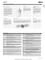 3
3
-
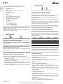 4
4
-
 5
5
-
 6
6
-
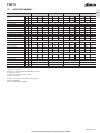 7
7
-
 8
8
-
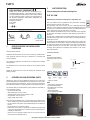 9
9
-
 10
10
-
 11
11
-
 12
12
-
 13
13
-
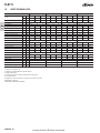 14
14
-
 15
15
-
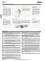 16
16
-
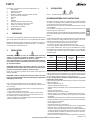 17
17
-
 18
18
-
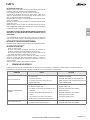 19
19
-
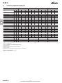 20
20
-
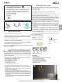 21
21
-
 22
22
-
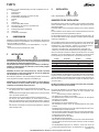 23
23
-
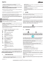 24
24
-
 25
25
-
 26
26
-
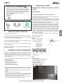 27
27
-
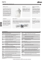 28
28
-
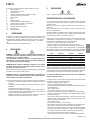 29
29
-
 30
30
-
 31
31
-
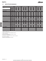 32
32
-
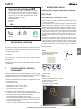 33
33
-
 34
34
-
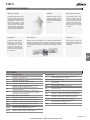 35
35
-
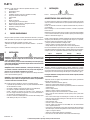 36
36
-
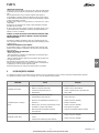 37
37
-
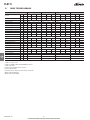 38
38
-
 39
39
-
 40
40
-
 41
41
-
 42
42
-
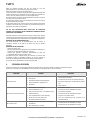 43
43
-
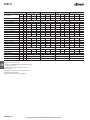 44
44
-
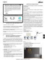 45
45
-
 46
46
-
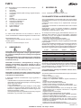 47
47
-
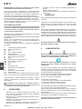 48
48
-
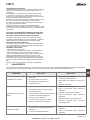 49
49
-
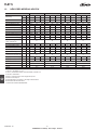 50
50
-
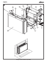 51
51
-
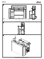 52
52
-
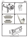 53
53
-
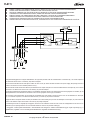 54
54
-
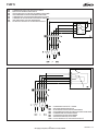 55
55
-
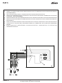 56
56
-
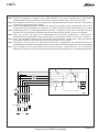 57
57
-
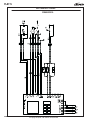 58
58
-
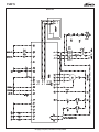 59
59
-
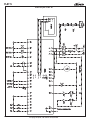 60
60
-
 61
61
-
 62
62


Galletti FLAT S Installation, Use And Maintenance Manual
- Tipo
- Installation, Use And Maintenance Manual
en otros idiomas
- français: Galletti FLAT S
- italiano: Galletti FLAT S
- Deutsch: Galletti FLAT S
- Nederlands: Galletti FLAT S
- português: Galletti FLAT S
Otros documentos
-
Samsung AG090MN4PKH/EU Manual de usuario
-
Samsung AG060MN4PKH/EU Manual de usuario
-
Trane WFS 3 Technical Manual
-
-
-
-
-
-
Trane DFS 1 Technical Manual
-
 Olimpia Splendid Bi2 SLI naked Guía de instalación
