Yamaha MD4 Manual de usuario
- Categoría
- Instrumentos musicales
- Tipo
- Manual de usuario
Este manual también es adecuado para

MULTITRACK MD RECORDER
MIC/LINE INPUT
AUX RETURN
STEREO SUB IN STEREO OUT MONITOR OUT TRACK DIRECT OUT
AUX SEND
1234
L R L R L R
L R
1 2 3 4
GAIN
LINE MIC
1 2
3 4
AUX
010
HIGH
–12 +12
MID
–12 +12
LOW
–12 +12
PAN
L
ODD
R
EVEN
PB MIC/
LINE
10
9
8
7
6
5
4
3
2
1
0
GAIN
LINE MIC
1 2
3 4
AUX
010
HIGH
–12 +12
MID
–12 +12
LOW
–12 +12
PAN
L
ODD
R
EVEN
PB MIC/
LINE
10
9
8
7
6
5
4
3
2
1
0
GAIN
LINE MIC
1 2
3 4
AUX
010
HIGH
–12 +12
MID
–12 +12
LOW
–12 +12
PAN
L
ODD
R
EVEN
PB MIC/
LINE
10
9
8
7
6
5
4
3
2
1
0
GAIN
LINE MIC
1 2
3 4
AUX
010
HIGH
–12 +12
MID
–12 +12
LOW
–12 +12
PAN
L
ODD
R
EVEN
PB MIC/
LINE
10
9
8
7
6
5
4
3
2
1
0
1 2 1 2
3 4 3 4
LEVEL
010
MONITOR LEVEL
MIN MAX
LEVEL
010
GROUP ASSIGN
1 3
2 4
GROUP
STEREO
CUE
GROUP ASSIGN
1
2
3
4
010
010
010
010
10
9
8
7
6
5
4
3
2
1
0
123
4
TIME
DISPLAY
REPEAT MEMO A/B
REC SELECT
MARK SEARCH
LAST REC SEARCH
IN OUT
MARKPITCH
ADJUST
UTILITY
CLEAR
ENTER
AUTO
PUNCH I/O
SELECT
DATA–+
SONG
SEARCH
REC
PLAY
PAUSE
REVIEW
FF CUE
STOP
TOC WRITE
1
2
34
MASTER
AUX
RETURN
STEREO
SUB IN
GROUP ASSIGN
GROUP ASSIGN GROUP ASSIGN GROUP ASSIGN
STEREO
PHONES PUNCH I/O
REHE
MONITOR
SELECT
CUE LEVEL
MULTITRACK MD RECORDER
Owner’s Manual
E

Laser Diode Properties
* Material : GaAlAs
* Wavelength : 780–790 nm
* Emission Duration : Continuous
* Laser Output Power : Less than 44.6 µW
Laser output is measured at a
distance of 20cm from the object
lens on the optical pick-up head.
(Note)
This unit is classified as a
Class 1 laser product.
The CLASS 1 LASER
PRODUCT label is located on
the exterior.
CLASS 1 LASER PRODUCT
Klassmärkning för Finland.
CLASS 1 LASER PRODUCT
LUOKAN 1 LASERLAITE
KLASS 1 LASERAPPARAT
ADVARSEL
Usynlig laserstråling ved åbning. Undgå udsaettelse
for stråling.
VAROITUS
Laitteen käyttäminen muulla kuin tässä käyttöohjeesa
mainitulla tavalla saattaa altistaa käyttäjän
turvallisuusluokan 1 ylittävälle näkymättömälle
lasersäteilylle.
VARNING
Om apparaten används på annat sätt än i denna
bruksanvisning specificerats, kan användaren utsättas
för osynlig laserstrålning, som överskrider gränsen för
laserklass 1.
CAUTION
USE OF CONTROLS OR ADJUSTMENTS OR
PERFORMANCE OF PROCEDURES OTHER
THAN THOSE SPECIFIED HEREIN MAY RESULT
IN HAZARDOUS RADIATION EXPOSURE.
•This label is not placed on USA model
and Canadian model.
•This label is placed on the lid.
•Varningsanvisning för laserstrålning.
Placerad i apparaten.
CAUTION : INVISIBLE LASER RADIATION WHEN OPEN AND INTRLOCKS DEFEATED.
DO NOT STARE INTO BEAM OR VIEW DIRECTLY WITH OPTICAL INSTRUMENTS.
VARNING : OSYNLIG LASERSTRÅLNING NÄR DENNA DEL ÄR ÖPPNAD OCH SPÄRRAR
ÄR URKOPPLADE. STIRRA EJ IN I STRÅLEN OCH BETRAKTA EJ STRÅLEN MED
OPISKA INSTRUMENT.
VARO! : NÄKYMÄTÖNTÄ AVATTAESSA JA SUOJALUKITUS OHITETTAESSA OLET
ALTTIINA LASERSÄTEILYLLE. ÄLÄ TUIJOTA SÄTEESEEN ÄLÄKÄ KATSO SITÄ
OPTISEN LAITTEEN LÄPI.
FCC INFORMATION (U.S.A.)
1. IMPORTANT NOTICE: DO NOT MODIFY THIS UNIT!
This product, when installed as indicated in the instructions contained in this
manual, meets FCC requirements. Modifications not expressly approved by
Yamaha may void your authority, granted by the FCC, to use the product.
2. IMPORTANT: When connecting this product to accessories and/or another
product use only high quality shielded cables. Cable/s supplied with this product
MUST be used. Follow all installation instructions. Failure to follow instructions
could void your FCC authorization to use this product in the USA.
3. NOTE: This product has been tested and found to comply with the requirements
listed in FCC Regulations, Part 15 for Class “B” digital devices. Compliance
with these requirements provides a reasonable level of assurance that your use of
this product in a residential environment will not result in harmful interference
with other electronic devices. This equipment generates/uses radio frequencies
and, if not installed and used according to the instructions found in the users
manual, may cause interference harmful to the operation of other electronic
devices. Compliance with FCC regulations does not guarantee that interference
will not occur in all installations. If this product is found to be the source of
interference, which can be determined by turning the unit “OFF” and “ON”,
please try to eliminate the problem by using one of the following measures:
Relocate either this product or the device that is being affected by the
interference.
Utilize power outlets that are on different branch (circuit breaker or fuse)
circuits or install AC line filter/s.
In the case of radio or TV interference, relocate/reorient the antenna. If the
antenna lead-in is 300 ohm ribbon lead, change the lead-in to coaxial type cable.
If these corrective measures do not produce satisfactory results, please contact
the local retailer authorized to distribute this type of product. If you can not
locate the appropriate retailer, please contact Yamaha Corporation of America,
Electronic Service Division, 6600 Orangethorpe Ave, Buena Park, CA 90620
IMPORTANT NOTICE FOR
THE UNITED KINGDOM
Connecting the Plug and Cord
IMPORTANT: The wires in this mains lead are coloured in accordance
with the following code:
BLUE : NEUTRAL
BROWN : LIVE
As the colours of the wires in the mains lead of this apparatus may not
correspond with the coloured markings identifying the terminals in your
plug proceed as follows:
The wire which is coloured BLUE must be connected to the terminal
which is marked with the letter N or coloured BLACK.
The wire which is coloured BROWN must be connected to the terminal
which is marked with the letter L or coloured RED.
Making sure that neither core is connected to the earth terminal of the
three pin plug.
IMPORTANT
Please record the serial number of this unit in the space below.
Serial No.:
The serial number is located on the bottom of the unit.
Retain this Owner's Manual in a safe place for future reference.

• Explanation of Graphical Symbols
The exclamation point within an equilateral tri-
angle is intended to alert the user to the presence of
important operating and maintenance (servicing)
instructions in the literature accompanying the
product.
The lightning flash with arrowhead symbol within
an equilateral triangle is intended to alert the user
to the presence of uninsulated “dangerous voltage”
within the product’s enclosure that may be of
sufficient magnitude to constitute a risk of electric
shock to persons.
10. Power Sources — The appliance should be connected to a power
supply only of the type described in the operating instructions or
as marked on the appliance.
11. Grounding or Polarization — The precautions that should be
taken so that the grounding or polarization means of an appliance
is not defeated.
12. Power-Cord Protection — Power-supply cords should be routed
so that they are not likely to be walked on or pinched by items
placed upon or against them, paying particular attention to cords
at plugs, convenience receptacles, and the point where they exit
from the appliance.
13. Cleaning — The appliance should be cleaned only as recom-
mended by the manufacturer.
14. Nonuse Periods — The power cord of the appliance should be
unplugged from the outlet when left unused for a long period of
time.
15. Object and Liquid Entry — Care should be taken so that objects
do not fall and liquids are not spilled into the enclosure through
openings.
16. Damage Requiring Service — The appliance should be serviced
by qualified service personnel when:
A. The power-supply cord or the plug has been damaged; or
B. Objects have fallen, or liquid has been spilled into the
appliance; or
C. The appliance has been exposed to rain; or
D. The appliance does not appear to operate normally or exhibits
a marked change in performance; or
E. The appliance has been dropped, or the enclosure damaged.
17. Servicing — The user should not attempt service the appliance
beyond that described in the operating instructions.
SAFETY INSTRUCTIONS
CAUTION: TO REDUCE THE RISK OF
ELECTRIC SHOCK, DO NOT REMOVE
COVER (OR BACK). NO USER-SERVICEABLE
PARTS INSIDE. REFER SERVICING TO
QUALIFIED SERVICE PERSONNEL.
SEE BOTTOM OF ENCLOSURE FOR GRAPHIC
SYMBOLS MARKING.
CAUTION
RISK OF ELECTRIC SHOCK
DO NOT OPEN
1. Read Instructions — All the safety and operating instructions
should be read before the appliance is operated.
2. Retain Instructions — The safety and operating instructions
should be retained for future reference.
3. Heed Warnings — All warnings on the appliance and in the
operating instructions should be adhered to.
4. Follow Instructions — All operating and use instructions should
be followed.
5. Water and Moisture — The appliance should not be used near
water – for example, near a bathtub, washbowl, kitchen sink,
laundry tub, in a wet basement, or near a swimming pool, and the
like.
6. Carts and Stands — The appliance should
be used only with a cart or stand that is
recommended by the manufacturer.
6A An appliance and cart combination
should be moved with care. Quick
stops, excessive force, and uneven
surfaces may cause the appliance and cart combination to
overturn.
7. Wall or Ceiling Mounting — The appliance should be mounted
to a wall or ceiling only as recommended by the manufacturer.
8. Ventilation — The appliance should be situated so that its
location or position does not interfere with its proper ventilation.
For example, the appliance should not be situated on a bed, sofa,
rug, or similar surface that may block the ventilation openings;
or, placed in a built-in installation, such as a bookcase or cabinet
that may impede the flow of air through the ventilation openings.
9. Heat — The appliance should be situated away from heat sources
such as radiators, heat registers, stoves, or other appliances
(including amplifiers) that produce heat.

iii
MD4—Owner’s Manual
Important
Read the Following Before Operating MD4
Warnings
• Do not locate MD4 in a place subject to excessive heat or in direct sunlight. This could be a
fire hazard.
• Do not place MD4 in a place subject to excessive humidity or dust. This could be a fire and
electrical shock hazard.
• Connect the supplied AC power cord only to an AC outlet of the type stated in this
Owner’s
Manual
or as marked on the main unit. Failure to do so is a fire and electrical shock hazard.
• Do not plug several devices into the same AC outlet. This can overload the AC outlet, and
can be a fire and electrical shock hazard. It may also affect the performance of some devices.
• Do not place heavy objects on the power cord. A damaged power cord is a potential fire and
electrical shock hazard.
• If the power cord is damaged (i.e., cut or a bare wire is exposed), ask your dealer for a
replacement. Using MD4 in this condition is a fire and shock hazard.
• Hold the AC power cord plug when disconnecting from an AC outlet. Never pull the cord.
Damaging the power cord in this way is a potential fire and electrical shock hazard.
• Do not place small metal objects on top of MD4. Metal objects inside MD4 are a fire and
electrical shock hazard.
• Do not block the MD4 ventilation holes. MD4 has ventilation holes at the rear to prevent
the internal temperature from rising. Blocked ventilation holes are a fire hazard.
• Do not try to modify MD4. This could be a fire and electrical shock hazard.
• MD4 operating temperature is between 5˚C and 35˚C (41˚F and 95˚F).
Cautions
• Turn off all audio devices and speakers when connecting to MD4. Refer to the owner’s man-
ual for each device. Use the correct cables and connect as specified.
• MD4 is a precision device. Handle it with care.
• Handle MD DATA discs with care.
• If you notice any abnormality—such as smoke, odor, or noise—turn off MD4 immediately.
Remove the AC power cord from the AC outlet. Confirm that the abnormality is no longer
present. Consult your dealer for repair. Using MD4 in this condition is a fire and shock
hazard.
• If a foreign object or water gets inside MD4, turn it off immediately. Remove the AC power
cord from the AC outlet. Consult your dealer for repair. Using MD4 in this condition is a
fire and electrical shock hazard.
• If you plan not to use MD4 for a long period of time (such as when you are on vacation),
remove the AC power cord from the AC outlet. Leaving MD4 connected is a fire hazard.
• Do not use benzene, thinner, cleaning detergent, or a chemical cloth to clean MD4.
• Use only a soft, dry cloth to clean MD4.

iv
MD4—Owner’s Manual
Interference
MD4 uses high-frequency digital circuits that may cause interference on radios and televisions
placed close to it. If interference does occur, relocate the affected equipment.
Copyright
© 1996 Yamaha Corporation. All rights reserved.
No part of the MD4 software or this
Owner’s Manual
may be reproduced or distributed in any
form or by any means without the prior written authorization of Yamaha Corporation.
Trademarks
MD DATA and MiniDisc are trademarks of Sony Corporation.
US and foreign patents licensed from Dolby Laboratories Licensing Corporation.
All trademarks are the property of their respective holders.
Package Contents
The MD4 package should contain the following items. Make sure that you have them all.
• MD4 Multitrack Recorder
• AC power cord
• MD DATA disc
• This Owner’s Manual
Contact your Yamaha dealer if something is missing.
Keep This Manual For Future Reference

v
MD4—Owner’s Manual
Contents
1. Welcome to MD4 . . . . . . . . . . . . . . . . . . . 1
MD4 Features . . . . . . . . . . . . . . . . . . . . . . . . . . . . . . . . . . . . . . . . . . . . . . . . . . 1
Mixer . . . . . . . . . . . . . . . . . . . . . . . . . . . . . . . . . . . . . . . . . . . . . . . . . . . . 1
Recorder . . . . . . . . . . . . . . . . . . . . . . . . . . . . . . . . . . . . . . . . . . . . . . . . . 1
Buying Discs for MD4 . . . . . . . . . . . . . . . . . . . . . . . . . . . . . . . . . . . . . . . . . . . 2
MD4 TOC . . . . . . . . . . . . . . . . . . . . . . . . . . . . . . . . . . . . . . . . . . . . . . . . . . . . . 2
2. Touring MD4 . . . . . . . . . . . . . . . . . . . . . . . 3
Topside View . . . . . . . . . . . . . . . . . . . . . . . . . . . . . . . . . . . . . . . . . . . . . . . . . . . 3
Input Channels . . . . . . . . . . . . . . . . . . . . . . . . . . . . . . . . . . . . . . . . . . . . . . . . . 4
Master Section . . . . . . . . . . . . . . . . . . . . . . . . . . . . . . . . . . . . . . . . . . . . . . . . . . 5
Display . . . . . . . . . . . . . . . . . . . . . . . . . . . . . . . . . . . . . . . . . . . . . . . . . . . . . . . . 6
Disc Transport Section . . . . . . . . . . . . . . . . . . . . . . . . . . . . . . . . . . . . . . . . . . . 8
Topside Connectors . . . . . . . . . . . . . . . . . . . . . . . . . . . . . . . . . . . . . . . . . . . . . 10
Front Connectors . . . . . . . . . . . . . . . . . . . . . . . . . . . . . . . . . . . . . . . . . . . . . . . 11
Rear . . . . . . . . . . . . . . . . . . . . . . . . . . . . . . . . . . . . . . . . . . . . . . . . . . . . . . . . . . . 11
3. The First Session . . . . . . . . . . . . . . . . . . . 12
Quick-Start System . . . . . . . . . . . . . . . . . . . . . . . . . . . . . . . . . . . . . . . . . . . . . . 12
Connecting the Power Cord . . . . . . . . . . . . . . . . . . . . . . . . . . . . . . . . . . . . . . . 13
Turning On MD4 . . . . . . . . . . . . . . . . . . . . . . . . . . . . . . . . . . . . . . . . . . . . . . . 13
Loading a Disc . . . . . . . . . . . . . . . . . . . . . . . . . . . . . . . . . . . . . . . . . . . . . . . . . . 13
Recording the First Track . . . . . . . . . . . . . . . . . . . . . . . . . . . . . . . . . . . . . . . . . 13
Listening to the First Track . . . . . . . . . . . . . . . . . . . . . . . . . . . . . . . . . . 14
Overdubbing . . . . . . . . . . . . . . . . . . . . . . . . . . . . . . . . . . . . . . . . . . . . . . . . . . . 15
Mixdown . . . . . . . . . . . . . . . . . . . . . . . . . . . . . . . . . . . . . . . . . . . . . . . . . . . . . . 16
An Overview of Multitrack Recording . . . . . . . . . . . . . . . . . . . . . . . . . . . . . . 17
Basic Multitracking . . . . . . . . . . . . . . . . . . . . . . . . . . . . . . . . . . . . . . . . 17
Advanced Multitracking . . . . . . . . . . . . . . . . . . . . . . . . . . . . . . . . . . . . 17
About Monitoring . . . . . . . . . . . . . . . . . . . . . . . . . . . . . . . . . . . . . . . . . . . . . . . 18
4. Recording & Mixing Techniques . . . . . . . 19
Recording a New Song . . . . . . . . . . . . . . . . . . . . . . . . . . . . . . . . . . . . . . . . . . . 19
Searching for the Blank Top . . . . . . . . . . . . . . . . . . . . . . . . . . . . . . . . . 19
Setting the Recording Mode . . . . . . . . . . . . . . . . . . . . . . . . . . . . . . . . . 19
Recording . . . . . . . . . . . . . . . . . . . . . . . . . . . . . . . . . . . . . . . . . . . . . . . . 20
Titling Discs & Songs . . . . . . . . . . . . . . . . . . . . . . . . . . . . . . . . . . . . . . . . . . . . 20
Manual Punch In/Out . . . . . . . . . . . . . . . . . . . . . . . . . . . . . . . . . . . . . . . . . . . 21
Using the REC Button . . . . . . . . . . . . . . . . . . . . . . . . . . . . . . . . . . . . . . 21
Using the REC SELECT buttons . . . . . . . . . . . . . . . . . . . . . . . . . . . . . 22
Using a Footswitch . . . . . . . . . . . . . . . . . . . . . . . . . . . . . . . . . . . . . . . . 23
Auto Punch In/Out . . . . . . . . . . . . . . . . . . . . . . . . . . . . . . . . . . . . . . . . . . . . . . 24
Setting the In/Out Points “On-the-Fly” . . . . . . . . . . . . . . . . . . . . . . . 24
Another Way to Set the IN/OUT Points . . . . . . . . . . . . . . . . . . . . . . . 24
Rehearsing Auto Punch . . . . . . . . . . . . . . . . . . . . . . . . . . . . . . . . . . . . . 25
Performing Auto Punch for Real . . . . . . . . . . . . . . . . . . . . . . . . . . . . . 26
Auto Punch with a Footswitch . . . . . . . . . . . . . . . . . . . . . . . . . . . . . . . 27
Setting the Pre-Roll & Post-Roll Times . . . . . . . . . . . . . . . . . . . . . . . . 28
Ping-Pong Recording . . . . . . . . . . . . . . . . . . . . . . . . . . . . . . . . . . . . . . . . . . . . 29

vi
MD4—Owner’s Manual
Preparing for Ping-Pong . . . . . . . . . . . . . . . . . . . . . . . . . . . . . . . . . . . 30
Rehearsing the Ping-Pong . . . . . . . . . . . . . . . . . . . . . . . . . . . . . . . . . . 30
Performing the Ping-Pong for Real . . . . . . . . . . . . . . . . . . . . . . . . . . 30
Checking the Ping-Pong Operation . . . . . . . . . . . . . . . . . . . . . . . . . . 31
Ping-Pong with Overdub . . . . . . . . . . . . . . . . . . . . . . . . . . . . . . . . . . . . . . . . 31
Pitch . . . . . . . . . . . . . . . . . . . . . . . . . . . . . . . . . . . . . . . . . . . . . . . . . . . . . . . . . 32
Adjusting the Pitch . . . . . . . . . . . . . . . . . . . . . . . . . . . . . . . . . . . . . . . . 32
Resetting the Pitch . . . . . . . . . . . . . . . . . . . . . . . . . . . . . . . . . . . . . . . . 32
Using a Footswitch . . . . . . . . . . . . . . . . . . . . . . . . . . . . . . . . . . . . . . . . . . . . . 33
Applying Effects . . . . . . . . . . . . . . . . . . . . . . . . . . . . . . . . . . . . . . . . . . . . . . . . 34
Applying Effects at Mixdown . . . . . . . . . . . . . . . . . . . . . . . . . . . . . . . 34
Applying Effects when Recording . . . . . . . . . . . . . . . . . . . . . . . . . . . . 35
Applying Effects with Ping-Pong . . . . . . . . . . . . . . . . . . . . . . . . . . . . 35
5. Quick Search Functions . . . . . . . . . . . . . . 36
Searching for Songs . . . . . . . . . . . . . . . . . . . . . . . . . . . . . . . . . . . . . . . . . . . . . 36
Searching by Time . . . . . . . . . . . . . . . . . . . . . . . . . . . . . . . . . . . . . . . . . . . . . . 36
Searching for the Last Rec IN and OUT Points . . . . . . . . . . . . . . . . . . . . . . 36
Searching for Markers . . . . . . . . . . . . . . . . . . . . . . . . . . . . . . . . . . . . . . . . . . . 36
Inserting Markers . . . . . . . . . . . . . . . . . . . . . . . . . . . . . . . . . . . . . . . . . . . . . . 37
Marker Indicators . . . . . . . . . . . . . . . . . . . . . . . . . . . . . . . . . . . . . . . . 37
Adjusting Markers . . . . . . . . . . . . . . . . . . . . . . . . . . . . . . . . . . . . . . . . . . . . . . 38
Erasing Markers . . . . . . . . . . . . . . . . . . . . . . . . . . . . . . . . . . . . . . . . . . . . . . . . 39
6. Repeat, Cue List & Program Play . . . . . . 40
One Song Repeat . . . . . . . . . . . . . . . . . . . . . . . . . . . . . . . . . . . . . . . . . . . . . . . 40
All Song Repeat . . . . . . . . . . . . . . . . . . . . . . . . . . . . . . . . . . . . . . . . . . . . . . . . 40
A–B Repeat . . . . . . . . . . . . . . . . . . . . . . . . . . . . . . . . . . . . . . . . . . . . . . . . . . . . 41
Cue List Playback & Copy . . . . . . . . . . . . . . . . . . . . . . . . . . . . . . . . . . . . . . . . 42
Program Playback . . . . . . . . . . . . . . . . . . . . . . . . . . . . . . . . . . . . . . . . . . . . . . 43
7. Editing Songs & Tracks . . . . . . . . . . . . . . 44
Copying a Song . . . . . . . . . . . . . . . . . . . . . . . . . . . . . . . . . . . . . . . . . . . . . . . . 44
Dividing a Song . . . . . . . . . . . . . . . . . . . . . . . . . . . . . . . . . . . . . . . . . . . . . . . . 45
Combining Songs . . . . . . . . . . . . . . . . . . . . . . . . . . . . . . . . . . . . . . . . . . . . . . 46
Track-to-Track Copy . . . . . . . . . . . . . . . . . . . . . . . . . . . . . . . . . . . . . . . . . . . 47
Erasing Tracks . . . . . . . . . . . . . . . . . . . . . . . . . . . . . . . . . . . . . . . . . . . . . . . . . 48
Erasing Songs . . . . . . . . . . . . . . . . . . . . . . . . . . . . . . . . . . . . . . . . . . . . . . . . . . 48
8. MD4 & MIDI . . . . . . . . . . . . . . . . . . . . . . 49
Using MD4 in a Synchronized MIDI System . . . . . . . . . . . . . . . . . . . . . . . . 49
About Tempo Maps . . . . . . . . . . . . . . . . . . . . . . . . . . . . . . . . . . . . . . . . . . . . . 49
Setting Up a Synchronized MIDI System . . . . . . . . . . . . . . . . . . . . . . . . . . . 50
Using MTC . . . . . . . . . . . . . . . . . . . . . . . . . . . . . . . . . . . . . . . . . . . . . . . . . . . . 51
Setting MD4 for MTC Operation . . . . . . . . . . . . . . . . . . . . . . . . . . . . 51
Setting the MIDI Sequencer . . . . . . . . . . . . . . . . . . . . . . . . . . . . . . . . 51
MTC Cabling Note . . . . . . . . . . . . . . . . . . . . . . . . . . . . . . . . . . . . . . . . 51
Using MIDI Clock . . . . . . . . . . . . . . . . . . . . . . . . . . . . . . . . . . . . . . . . . . . . . . 52
Setting the MIDI Sequencer . . . . . . . . . . . . . . . . . . . . . . . . . . . . . . . . 52
Adding Meter Changes to a Tempo Map . . . . . . . . . . . . . . . . . . . . . . 52
Adding Tempo Changes to a Tempo Map . . . . . . . . . . . . . . . . . . . . . 53
Inserting Steps in a Tempo Map . . . . . . . . . . . . . . . . . . . . . . . . . . . . . 54

vii
MD4—Owner’s Manual
Deleting Steps in a Tempo Map . . . . . . . . . . . . . . . . . . . . . . . . . . . . . . 54
Saving a Tempo Map . . . . . . . . . . . . . . . . . . . . . . . . . . . . . . . . . . . . . . . 55
Loading a Tempo Map . . . . . . . . . . . . . . . . . . . . . . . . . . . . . . . . . . . . . 55
Tempo Map Chart . . . . . . . . . . . . . . . . . . . . . . . . . . . . . . . . . . . . . . . . . . . . . . 56
9. MD4 Applications . . . . . . . . . . . . . . . . . . 57
One-Take Recording . . . . . . . . . . . . . . . . . . . . . . . . . . . . . . . . . . . . . . . . . . . . . 57
MIDI Home Studio . . . . . . . . . . . . . . . . . . . . . . . . . . . . . . . . . . . . . . . . . . . . . . 58
Using MD4 with a Sub-Mixer . . . . . . . . . . . . . . . . . . . . . . . . . . . . . . . . . . . . . 59
Recording a Stereo Source . . . . . . . . . . . . . . . . . . . . . . . . . . . . . . . . . . . . . . . . 60
10. Beyond the Basics . . . . . . . . . . . . . . . . . 61
AUX RETURN . . . . . . . . . . . . . . . . . . . . . . . . . . . . . . . . . . . . . . . . . . . . . . . . . 61
EQ . . . . . . . . . . . . . . . . . . . . . . . . . . . . . . . . . . . . . . . . . . . . . . . . . . . . . . . . . . . . 61
Markers . . . . . . . . . . . . . . . . . . . . . . . . . . . . . . . . . . . . . . . . . . . . . . . . . . . . . . . 61
Pitch . . . . . . . . . . . . . . . . . . . . . . . . . . . . . . . . . . . . . . . . . . . . . . . . . . . . . . . . . . 62
Monitoring . . . . . . . . . . . . . . . . . . . . . . . . . . . . . . . . . . . . . . . . . . . . . . . . . . . . 62
Mixdown . . . . . . . . . . . . . . . . . . . . . . . . . . . . . . . . . . . . . . . . . . . . . . . . . . . . . . 63
11. Q&A Section . . . . . . . . . . . . . . . . . . . . . 64
Troubleshooting . . . . . . . . . . . . . . . . . . . . . 66
Appendix . . . . . . . . . . . . . . . . . . . . . . . . . . . 67
MD4 Transport Modes . . . . . . . . . . . . . . . . . . . . . . . . . . . . . . . . . . . . . . . . . . . 67
Display Messages . . . . . . . . . . . . . . . . . . . . . . . . . . . . . . . . . . . . . . . . . . . . . . . . 68
Signal Flow Chart . . . . . . . . . . . . . . . . . . . . . . . . . . . . . . . . . . . . . . . . . . . . . . . 69
Specifications . . . . . . . . . . . . . . . . . . . . . . . . . . . . . . . . . . . . . . . . . . . . . . . . . . . 70
Recorder . . . . . . . . . . . . . . . . . . . . . . . . . . . . . . . . . . . . . . . . . . . . . . . . . 70
Mixer . . . . . . . . . . . . . . . . . . . . . . . . . . . . . . . . . . . . . . . . . . . . . . . . . . . . 70
General . . . . . . . . . . . . . . . . . . . . . . . . . . . . . . . . . . . . . . . . . . . . . . . . . . 70
Block Diagram . . . . . . . . . . . . . . . . . . . . . . . . . . . . . . . . . . . . . . . . . . . . . . . . . . 71
Dimensions . . . . . . . . . . . . . . . . . . . . . . . . . . . . . . . . . . . . . . . . . . . . . . . . . . . . 71
Glossary . . . . . . . . . . . . . . . . . . . . . . . . . . . . 72
Index . . . . . . . . . . . . . . . . . . . . . . . . . . . . . . 75
MIDI Implementation Chart . . End of Manual

Welcome to MD4
1
MD4—Owner’s Manual
1
Welcome to MD4
Thank you for choosing the Yamaha MD4 Multitrack MD Recorder. MD4 is the world’s first
multitrack recorder to use the MiniDisc format, with its superior sound quality and quick search
capabilities. To take best advantage of your MD4, read this
Owner’s Manual
thoroughly.
MD4 Features
Mixer
The mixer section is a four-input channel, four-group analog mixer.
• Input channels feature continuously variable GAIN controls, which can handle both micro-
phone and line-level signals with ease.
• Musical three-band EQ (High, Mid, Low) on each input channel provides flexible
tone-shaping capabilities.
• Aux send with stereo return for an external effects processor.
• Flexible monitoring of Group, CUE, and Stereo buses.
• Direct outputs for direct connection to another mixer.
• Stereo sub inputs for mixer cascading.
Recorder
The recorder section is a four-track recorder based on the MD DATA audio format, which has
several advantages over tape-based multitrackers. With a tape-based recorder, for example, you
have to keep at least one track free for ping-pong. With MD4, however, you can record on all
four tracks and then ping-pong (i.e., four-track playback with ping-pong). This is because
MD4 can simultaneously play and record on the same track. This feature provides greater cre-
ative freedom when planing tracks.
• Superior sound quality that is unaffected by repeated overdubs and ping-pong operations.
• Zero wow and flutter and pitch fluctuation.
• Recording time: 37 minutes for 4-track, 74 minutes for stereo, and 148 minutes for mono.
• Four-track playback with ping-pong.
• Quick search for Song Start, Song End, Last Record IN/OUT points, Direct Time Locate,
and up to eight markers for each song.
• Precise punch in/out with 11-millisecond accuracy.
• Editing includes Song Combine, Song Divide, and cue list-style playback.
• Disc and song titling for easy identification.
• Repeat modes include One Song, All Song, A–B, and Auto Punch Rehearse.
• FF CUE and Review at 2X and 4X playback speed.
• Variable pitch of approximately
±
6.5%.
• Clear FLD (Fluorescent Display) shows signal levels, mode, status, and Total, Remaining,
and Elapsed times.
• MTC (MIDI Timecode) or MIDI Clock (with Tempo Map) output for synchronization
within a MIDI-based system.
For some more quick answers on MD4, see the
Q&A Section
on page 64.

2
Welcome to MD4
MD4—Owner’s Manual
Buying Discs for MD4
It’s important that you buy the correct type of disc for use with your MD4. For 4-track recording
and playback, you must use MD DATA discs. Normal MiniDiscs can only be used for 2-track
recording and playback.
MD DATA discs are used as a storage media for computers. MD4 uses the MD DATA audio for-
mat. MiniDiscs are also referred to as MD discs, although they are used only for music.
MD DATA discs that have been used to store computer data must be formatted before they can
be used with MD4. See
Erasing Songs
on page 48.
Normal MiniDisc decks cannot play MD DATA discs.
MiniDiscs recorded on MD4 can be played on a normal MiniDisc deck.
MiniDisc recordings made on a normal MiniDisc deck can be edited on MD4. MiniDiscs that
contain songs that were digitally copied from a commercial CD, however, cannot be edited due
to the SCMS protection system.
MD4 TOC
TOC refers to the Table Of Contents area on a disc. The TOC contains information about what
is recorded on the disc, the disc title, song titles, and so on. The TOC EDIT indicator lights up
when the TOC needs to be updated, usually after a new recording or edit. You must update the
TOC before ejecting a disc or turning off MD4. It’s also a good idea to update the TOC at regular
intervals just in case of a power failure. Failure to update the TOC can result in data being lost.
Even if you’ve recorded something correctly, if the TOC isn’t updated and MD4 is turned off,
the power cord accidentally disconnected, or a power failure occurs, that data will be lost.
Type Logo Description
MD DATA
MD DATA discs are for computer data storage appli-
cations. You can purchase them at computer stores.
This is the type of disc you should buy for 4-track
recording and playback with your MD4. Note that
there are two types available:
playback only
and
rewritable
. You should buy the rewritable type.
MiniDisc
MiniDiscs are used only for music. Two types are
available:
playback only
and
recordable
. MD4 can
record up to two tracks on the
recordable
type and
play the
playback only
type.
Note:
If you press the EJECT button while TOC EDIT is shown on the display, the disc will
not eject. Press [TOC WRITE] to update the TOC, and then eject the disc.

Touring MD4
3
MD4—Owner’s Manual
2
Touring MD4
This chapter takes you on a tour of MD4, identifying the various parts to help you become famil-
iar with your new recorder.
Topside View
The individual sections of MD4 are explained on the following pages.
MULTITRACK MD RECORDER
MIC/LINE INPUT
AUX RETURN
STEREO SUB IN STEREO OUT MONITOR OUT TRACK DIRECT OUT
AUX SEND
1234
L R L R L R
L R
1 2 3 4
GAIN
LINE MIC
1 2
3 4
AUX
010
HIGH
–12 +12
MID
–12 +12
LOW
–12 +12
PAN
L
ODD
R
EVEN
PB MIC/
LINE
10
9
8
7
6
5
4
3
2
1
0
GAIN
LINE MIC
1 2
3 4
AUX
010
HIGH
–12 +12
MID
–12 +12
LOW
–12 +12
PAN
L
ODD
R
EVEN
PB MIC/
LINE
10
9
8
7
6
5
4
3
2
1
0
GAIN
LINE MIC
1 2
3 4
AUX
010
HIGH
–12 +12
MID
–12 +12
LOW
–12 +12
PAN
L
ODD
R
EVEN
PB MIC/
LINE
10
9
8
7
6
5
4
3
2
1
0
GAIN
LINE MIC
1 2
3 4
AUX
010
HIGH
–12 +12
MID
–12 +12
LOW
–12 +12
PAN
L
ODD
R
EVEN
PB MIC/
LINE
10
9
8
7
6
5
4
3
2
1
0
1 2 1 2
3 4 3 4
LEVEL
010
MONITOR LEVEL
MIN MAX
LEVEL
010
GROUP ASSIGN
1 3
2 4
GROUP
STEREO
CUE
GROUP ASSIGN
1
2
3
4
010
010
010
010
10
9
8
7
6
5
4
3
2
1
0
123
4
TIME
DISPLAY
REPEAT MEMO A/B
REC SELECT
MARK SEARCH
LAST REC SEARCH
IN OUT
MARKPITCH
ADJUST
UTILITY
CLEAR
ENTER
AUTO
PUNCH I/O
SELECT
DATA– +
SONG
SEARCH
REC
PLAY
PAUSE
REVIEW
FF CUE
STOP
TOC WRITE
1
2
34
MASTER
AUX
RETURN
STEREO
SUB IN
GROUP ASSIGN
GROUP ASSIGN GROUP ASSIGN GROUP ASSIGN
STEREO
PHONES PUNCH I/O
REHE
MONITOR
SELECT
CUE LEVEL

4
Touring MD4
MD4—Owner’s Manual
Input Channels
1
GAIN control
This rotary control adjusts the sensitivity of the MIC/LINE input so that both micro-
phone and line-level signals can be handled with ease.
2
EQ controls
These rotary controls are used to boost and cut the high, middle, and low frequency
bands independently. A flat setting (i.e., no boost or cut) can be set quickly using the
control’s center detent.
3
AUX control
This rotary control is used to send the input channel signal to the AUX SEND output
for processing by an external effects processor.
4
GROUP ASSIGN switches
These switches are used to assign (i.e., send) the input channel signal to the recorder’s
tracks. They work in conjunction with the PAN control. For example, with GROUP
ASSIGN switch [1–2] ON and the PAN control set midway, the channel signal is sent
equally to Tracks 1 and 2. With the PAN control turned fully counterclockwise (L/ODD),
however, the channel signal is sent only to Track 1. Likewise, when it is set fully clockwise,
the signal is sent only to track 2. The same principle applies to GROUP ASSIGN switch
[3–4].
5
PAN control
This rotary control has two functions: For recording it’s used in conjunction with the
GROUP ASSIGN switches to assign the input channel signal to even and odd numbered
tracks. For mixdown it’s used to pan (i.e., position) the signal in the stereo mix.
6
Input source selector switch
This switch is used to select the signal source for the input channel: MIC/LINE input or
PB (disc playback signal).
7
Fader
This fader has two functions: For recording it’s used to adjust the level of the input chan-
nel signal that’s recorded to a track. For mixdown it’s used to balance the input channel
signal relative to the other input channel signals. For optimum performance, faders
should be positioned about the 7–8 mark.
GAIN
LINE MIC
1 2
3 4
AUX
010
HIGH
–12 +12
MID
–12 +12
LOW
–12 +12
PAN
L
ODD
R
EVEN
PB MIC/
LINE
10
9
8
7
6
5
4
3
2
1
0
1
GROUP ASSIGN
1
2
3
4
5
6
7
10k 20k1k10020
–15
–10
–5
0
5
10
15
Frequency (Hz)
Response (dB)
50
5k2k500200
HIGH ±12 dB at 12 kHz—shelving type
MID ±12 dB at 1 kHz—peaking type
LOW ±12 dB at 80 Hz—shelving type

Master Section
5
MD4—Owner’s Manual
Master Section
1
AUX RETURN GROUP ASSIGN switches
These switches are used to assign (i.e., send) the Aux Return signals to
the recorder’s tracks. The left-channel signal is sent to odd buses 1 and
3. While the right-channel signal is sent to even buses 2 and 4. The Aux
Return signals are typically the processed signals returned from a ste-
reo effects processor. Note that the Aux Return signals are always sent
to the Stereo bus for mixing regardless of these switch settings.
2
AUX RETURN LEVEL control
This rotary control adjusts the level of the Aux Return signals that are
sent to the Stereo bus for mixing. It’s also used in conjunction with the
AUX RETURN GROUP ASSIGN switches to adjust the level of the Aux
Return signals that are assigned to the recorder’s tracks.
3
MONITOR SELECT switches
These switches are used to select the signal source for the MONITOR
OUT and headphones.
GROUP
—These switches select the Group buses as the monitor
source. This allows you to monitor signals assigned to tracks. When
only the [1–3] or [2–4] switch is pressed, the monitor signal is mono.
Press both switches to monitor stereo signals.
STEREO
—This switch selects the Stereo bus as the monitor source.
This allows you to monitor the STEREO OUT signal and is typically
used during mixdown.
CUE
—This switch selects the CUE bus as the monitor source. This
allows you to monitor track signals, which is useful for punch in/out.
4
MONITOR LEVEL control
This rotary control adjusts the level of the monitor signal that is sent
to the MONITOR OUT and headphones.
5
STEREO fader
This fader is used to adjust the level of the stereo signal that is sent to
the STEREO OUT. For optimum performance this fader should be
positioned about the 7–8 mark.
6
STEREO SUB IN GROUP ASSIGN switches
These switches are used to assign (i.e., send) the Stereo Sub In signals
to the recorder’s tracks. The left-channel signal is sent to odd buses 1
and 3. While the right-channel signal is sent to even buses 2 and 4. The
Stereo Sub In signals are typically the stereo output signals from
another mixer. Note that the Stereo Sub In signals are always sent to
the Stereo bus for mixing regardless of these switch settings.
7
STEREO SUB IN LEVEL control
This rotary control adjusts the level of the Stereo Sub In signals that are sent to the Stereo bus
for mixing. It’s also used in conjunction with the STEREO SUB IN GROUP ASSIGN switches
to adjust the level of the Stereo Sub In signals that are assigned to the recorder’s tracks.
8
CUE LEVEL controls
These controls adjust the level of the CUE signal for each track. During recording, or when no
disc is inserted, the CUE source is the signal assigned to a track. During playback, the CUE
source is the disc playback signal.
1 2 1 2
3 4 3 4
LEVEL
010
MONITOR LEVEL
MIN MAX
LEVEL
010
GROUP ASSIGN
1 3
2 4
GROUP
STEREO
CUE
GROUP ASSIGN
1
2
3
4
010
010
010
010
10
9
8
7
6
5
4
3
2
1
0
MASTER
AUX
RETURN
STEREO
SUB IN
STEREO
MONITOR
SELECT
CUE LEVEL
4
2 7
1
3
5
6
8

6
Touring MD4
MD4—Owner’s Manual
Display
Note: For explanation purposes, the illustration above shows most of the available indicators.
During normal operation, however, you will not see so many indicators on the display at the
same.
1 Status indicators
These indicators show the current operating mode.
2 Disc type indicators
These indicators show the type of disc loaded: MD DATA Disc or MiniDisc.
3 MASTER and MTC indicators
These indicators light up when MIDI synchronization is used. MASTER appears when the MD4
is generating MIDI Clock, and MTC appears when it is generating MIDI Timecode.
4 Pitch indicators
These indicators show the current Pitch mode: FIX (fixed) or VARI (variable).
5 TOC EDIT indicator
The TOC EDIT indicator lights up when the TOC needs to be updated, usually after a new
recording or edit.
Indicator Meaning
Normal playback
Cue or Review
Playback is paused
Rehearse Pause mode
Rehearsal in progress
Record Pause mode
Recording in progress
MD4 Song
MIN.
SEC. FRAMES
CLIP
–3
–6
–9
–12
–15
–18
–27
–39
+12
+9
+6
+3
0
–3
–6
–10
–20
MASTER
MTC
PITCH FIX VARI
TOC EDIT
REHE
REC
MARKERS
S12345678E PRE IN
OUT
1
2 3 4
L R
dBdB
POST
MEMO BPUNCHAUTOMEMO AREPEAT
1 ALL
ELAPSE
REMAIN
TOTAL
1
4 5 6 8 9
C
BA
7
2
3
D
0
REHE
REHE
REC
REC

Display 7
MD4—Owner’s Manual
6 Time Counter mode
These indicators show the Time Counter mode.
ELAPSE—This mode shows the time position within a song.
REMAIN—This mode shows the time remaining for a song or when you are recording a new
song, it shows the available time remaining for the song.
TOTAL—This mode shows the time position within the entire disc.
7 Title and function display
Disc titles, song titles, functions, messages, and other information appear here.
8 Time counter
The time counter shows the disc time in minutes, seconds, and frames.
9 Track level meters
These track level meters show group signal levels from –39 dB to –3 dB in 9 steps. A CLIP indi-
cator warns of possible distortion caused by signal clipping. With no disc loaded, the meters
display group signal levels.
0 Stereo level meters
These level meters show the STEREO OUT signal levels from –20 dB to +12 dB in 9 steps.
A Markers
These indicators show the status of the Start, End, and eight markers in between. When a song
is recorded, Start and End markers are recorded automatically. You can also add up to eight
markers per song while recording is in progress or during subsequent playback. When a song
is positioned on or after a marker (stopped, playing, paused, or recording) that marker flashes.
When the beginning of a song is located, the Start marker flashes. When the end is located, the
End marker flashes.
B Repeat mode indicators
These indicators show the Repeat modes.
REPEAT 1—The current song is played repeatedly (One Song Repeat).
REPEAT ALL—All songs are played repeatedly (All Song Repeat).
REPEAT MEMO A–MEMO B—Playback cycles between memo points A and B (A–B Repeat).
REPEAT Auto Punch I/O—Auto Punch In/Out is rehearsed repeatedly.
C AUTO PUNCH, PRE, IN, OUT & POST indicators
The AUTO PUNCH indicator shows that the AUTO PUNCH In/Out function is ON. The IN
and OUT indicators light up when the LAST REC IN and OUT points have been set. When a
song is positioned on or after the PRE, IN, OUT, or POST point, the corresponding indicator
flashes.
PRE—This indicator flashes when a song is at the Pre-Roll point.
IN—This indicator lights up when the LAST REC IN point has been set and it disappears when
a song is located on or after the specified IN point.
OUT—This indicator lights up when the LAST REC OUT point has been set and it disappears
when a song is located on or after the specified OUT point.
POST—This indicator flashes when the song is located at the Post-Roll point.
D Track record indicators
These indicators show which tracks are selected for recording.

8 Touring MD4
MD4—Owner’s Manual
Disc Transport Section
1 AUTO PUNCH I/O button
This button is used to turn on the Auto Punch In/Out function.
2 UTILITY button
This button is used to access the following functions: Rec Mode, Text, PrePost Roll,
OffLinePunch, Track Erase, Song Erase, Song Copy, Song Divide, Song Combine, Cue List, PRG
Play, and MIDI Sync.
3 ADJUST button
This button is used to adjust the position of markers and the LAST REC IN and OUT points.
4 PITCH button
This button is used to set the Pitch mode: FIX (fixed) or VARI (variable).
5 TIME DISPLAY button
This button is used to select the Time Counter mode: ELAPSE, REMAIN, or TOTAL.
6 SELECT buttons
These buttons are used to select items on the display.
7 REPEAT button
This button is used to select the One Song, All Song, A–B, and Auto Punch Rehearse Repeat
modes. It’s also be used to cancel A–B Repeat mode.
8 MEMO A/B buttons
These buttons are used to enter the A and B points for A–B Repeat.
123
4
TIME
DISPLAY
REPEAT MEMO A/B
REC SELECT
MARK SEARCH
LAST REC SEARCH
IN OUT
MARKPITCH
ADJUST
UTILITY
CLEAR
ENTER
AUTO
PUNCH I/O
SELECT
DATA– +
SONG
SEARCH
REC
PLAY
PAUSE
REVIEW
FF CUE
STOP
TOC WRITE
PHONES PUNCH I/O
REHE
5
4
3
2
1
D
H
C
B
A
7
EFG
6 8 9 0
4

Disc Transport Section 9
MD4—Owner’s Manual
9 CLEAR button
This button is used to cancel functions and delete characters in disc and song titles.
0 REC SELECT buttons
These buttons are used to select tracks for recording.
A MARK SEARCH buttons
These buttons are used to locate song markers.
B MARK button
This button is used to enter markers during recording or playback.
C LAST REC SEARCH IN/OUT buttons
These buttons are used to locate the LAST REC IN and OUT points.
D SONG SEARCH buttons
These buttons are used to search for songs.
E Disc Transport buttons
REHE—This button is used to enter Rehearse mode. The REHE indicators flash in Rehearse
Pause mode and stay on continuously while rehearsal is in progress.
REC—This button is used to enter Record mode. The REC indicators flash in Record Pause
mode and stay on continuously while recording is in progress.
PLAY—This button is used to start normal playback, start rehearsal, and start recording. It can
also be used to cancel rehearsal and recording. In this case, normal playback continues from the
point at which the [PLAY] button is pressed. The PLAY indicators light up while playback is in
progress and flash when playback is paused.
PAUSE—This button is used to pause playback, recording, or rehearsal.
REVIEW—This button is used to start review (i.e., review the song at a speed higher than nor-
mal playback). One press reviews at 2-times normal speed, while two presses review at 4-times
normal speed. The review speed is shown on the display: REV X2 or REV X4. You can toggle
between the X2 and X4 review speeds by pressing the [REVIEW] button. Review can be started
from stop, pause, or while playback is in progress.
FF CUE—This button is used to start FF CUE (i.e., preview the song at a speed higher than
normal playback). One press cues at 2-times normal speed, while two presses cue at 4-times nor-
mal speed. The cue speed is shown on the display: FF X2 or FF X4. You can toggle between X2
and X4 cue speeds by pressing the [FF CUE] button. FF CUE can be started from stop, pause,
or while playback is in progress.
When using the review or FF CUE function, the time counter may occasionally stop. This is not
a fault.
STOP/TOC WRITE—This button is used to stop playback, review, cue, rehearsal, and record-
ing. It’s also used to write the TOC data to disc when MD4 is stopped.
F ENTER button
This button is used to set functions.
G DATA –/+ buttons
These buttons are used to set parameters.
H EJECT button
This button is used to eject the disc.
Note: If you press the EJECT button while TOC EDIT is shown on the display, the disc will
not eject. Press [TOC WRITE] to update the TOC, and then eject the disc.

10 Touring MD4
MD4—Owner’s Manual
Topside Connectors
1 STEREO SUB IN
These phono jacks are used to connect another mixer to MD4 to increase the number of available
input channels. The stereo output signals from the other mixer can be mixed into the MD4 ste-
reo mix or recorded to MD4 tracks. Connect them to the other mixer’s stereo outputs.
2 STEREO OUT
These phono jacks are used to connect a stereo master recorder for recording the final mix. The
master recorder could be a DAT recorder, MiniDisc recorder, or cassette tape deck. Connect
them to your master recorder’s stereo inputs.
3 MONITOR OUT
These phono jacks are used to send the monitor signals to a stereo monitor amplifier and speak-
ers. This could be a dedicated monitor amplifier and speakers or your hi-fi system. Connect
them to the monitor amplifier’s stereo inputs. The MONITOR OUT signal is the same as the
headphone signal.
4 TRACK DIRECT OUTs
These phono jacks are used to send the disc playback signals to another mixer. This is useful
when you use MD4 in conjunction with a larger mixer. Connect them to the line inputs on the
other mixer. With no disc loaded, the DIRECT OUTs output the group signals.
5 MIC/LINE INPUTs
These 1/4-inch phone jacks are used to connect microphones, electronic musical instruments,
and other line-level sound sources to MD4.
6 AUX RETURN
These 1/4-inch phone jacks are used to return the processed stereo signals from an external
effects processor. The processed signals can then be mixed into the MD4 stereo mix or recorded
to tracks. Connect them to the effects processor’s stereo outputs.
7 AUX SEND
This 1/4-inch phone jack is used to send the Aux Send signal to an external effects processor.
Connect it to the effects processor’s input.
MIC/LINE INPUT
AUX RETURN
STEREO SUB IN STEREO OUT MONITOR OUT TRACK DIRECT OUT
AUX SEND
1234
L R L R L R
L R
1 2 3 4
1 2 3 4
65 7

Front Connectors 11
MD4—Owner’s Manual
Front Connectors
1 PHONES
A pair of stereo headphones can be connected here for monitoring. The headphone signal is
the same as the MONITOR OUT signal.
2 PUNCH I/O
An optional footswitch, such as the Yamaha FC5, can be connected here for foot-controlled play-
back, rehearsal, recording, or punch in/out.
Rear
1 AC IN
Connect the supplied power cord here.
2 POWER ON/OFF switch
This switch is used to turn on and off MD4.
3 MIDI OUT
This connector is used to send MTC (MIDI Timecode) or MIDI Clock to a MIDI sequencer for
synchronized operation. Connect it to the MTC or MIDI IN connector on your MIDI sequencer.
1 2
AC IN POWER
ON/OFF
MIDI OUT
1 2 3
CAUTION
TO PREVENT ELECTRIC SHOCK,
MATCH WIDE BLADE OF PLUG TO
WIDE SLOT, FULLY INSERT.

12 The First Session
MD4—Owner’s Manual
3 The First Session
This chapter explains how to record and mix your first MD4 session. If this is your first time
with a multitrack recorder, we recommend that you start with this chapter and follow all the
procedures closely. When you’ve completed this chapter, have a look at subsequent chapters,
which explain more advanced MD4 functions and require a basic knowledge of MD4 and mul-
titrack recording techniques.
Quick-Start System
The following illustration shows the basic equipment necessary to start recording with MD4.
The microphone, synthesizer, and guitar are examples of the kind of sound sources that can be
connected to MD4. For monitoring, you can use either headphones or a monitor amp and
speakers. Alternatively, you could use your hi-fi amp and speakers. The master recorder is
required for mixdown.
Monitors
Synthesizer
Master Recorder
Connect to an
appropriate
Wall Outlet
Guitar Processor
Headphones
Monitor Amp
Microphone
MULTITRACK MD RECORDER
MIC/LINE INPUT
AUX RETURN
STEREO SUB IN STEREO OUT MONITOR OUT TRACK DIRECT OUT
AUX SEND
1234
L R L R L R
L R
1 2 3 4
GAIN
LINE MIC
1 2
3 4
AUX
010
HIGH
–12 +12
MID
–12 +12
LOW
–12 +12
PAN
L
ODD
R
EVEN
PB MIC/
LINE
10
9
8
7
6
5
4
3
2
1
0
GAIN
LINE MIC
1 2
3 4
AUX
010
HIGH
–12 +12
MID
–12 +12
LOW
–12 +12
PAN
L
ODD
R
EVEN
PB MIC/
LINE
10
9
8
7
6
5
4
3
2
1
0
GAIN
LINE MIC
1 2
3 4
AUX
010
HIGH
–12 +12
MID
–12 +12
LOW
–12 +12
PAN
L
ODD
R
EVEN
PB MIC/
LINE
10
9
8
7
6
5
4
3
2
1
0
GAIN
LINE MIC
1 2
3 4
AUX
010
HIGH
–12 +12
MID
–12 +12
LOW
–12 +12
PAN
L
ODD
R
EVEN
PB MIC/
LINE
10
9
8
7
6
5
4
3
2
1
0
1 2 1 2
3 4 3 4
LEVEL
010
MONITOR LEVEL
MIN MAX
LEVEL
010
GROUP ASSIGN
1 3
2 4
GROUP
STEREO
CUE
GROUP ASSIGN
1
2
3
4
010
010
010
010
10
9
8
7
6
5
4
3
2
1
0
123
4
TIME
DISPLAY
REPEAT MEMO A/B
REC SELECT
MARK SEARCH
LAST REC SEARCH
IN OUT
MARKPITCH
ADJUST
UTILITY
CLEAR
ENTER
AUTO
PUNCH I/O
SELECT
DATA– +
SONG
SEARCH
REC
PLAY
PAUSE
REVIEW
FF CUE
STOP
TOC WRITE
1
2
34
MASTER
AUX
RETURN
STEREO
SUB IN
GROUP ASSIGN
GROUP ASSIGN GROUP ASSIGN GROUP ASSIGN
STEREO
PHONES PUNCH I/O
REHE
MONITOR
SELECT
CUE LEVEL

Connecting the Power Cord 13
MD4—Owner’s Manual
Connecting the Power Cord
1. Connect the supplied power cord to the AC IN socket on the rear of MD4.
2. Plug the other end of the power cord into a suitable AC wall outlet.
Turning On MD4
1. Press the POWER switch at the rear of MD4. The display lights up.
To turn off MD4, press the POWER switch again.
Loading a Disc
1. Press the EJECT button to open the disc compartment.
2. Insert the disc into the compartment with the arrow pointing forward.
The disc should slide easily into the compartment and click into place. If it doesn’t, make sure
you’ve inserted it the right way around (arrow forward).
3. Close the disc compartment.
When a disc is loaded, MD4 reads the TOC to see what the disc contains. If it’s a new disc, the
message
Blank Disc appears. If the disc contains some songs, the disc title appears for a few
seconds and then scrolls off the display. After that, the total number of songs on the disc is shown.
For example,
Total 004
Recording the First Track
1. Connect a sound source to MIC/LINE INPUT 1.
2. If you connect a line-level source, set the GAIN control to LINE (i.e., fully
counterclockwise). If you connect a microphone, set the GAIN control mid-
way. The GAIN control is adjusted again later on in this procedure.
3. Set the input selector switch on Input Channel 1 to MIC/LINE.
4. Press the GROUP ASSIGN [1–2] switch on Input Channel 1.
This assigns the Channel 1 signal to Tracks 1 and 2.
The following table show the relationship between Groups and Tracks.
5. Turn the PAN control to L/ODD.
This sends the signal to just Track 1.
Assigned to... Destination Track
Group 1 → Track 1
Group 2 → Track 2
Group 3 → Track 3
Group 4 → Track 4
POWER
ON/OFF

14 The First Session
MD4—Owner’s Manual
The following table show the relationship between the PAN control and Group/Tracks.
6. Press the MONITOR SELECT [1–3] switch.
This sets the monitor source to Track 1.
7. Set the MONITOR LEVEL control midway.
8. Raise Channel 1 fader to the 7–8 mark.
You should now be able to hear the sound source. If you don’t hear anything, recheck the pre-
ceding steps.
9. Press REC SELECT button [1].
A circle flashes around track indicator 1.
10. Press the [REC] button.
The REC indicators flash, indicating Record Pause mode. Track 1 meter shows the signal level.
11. Adjust the GAIN control on Channel 1 so that the loudest sounds cause the
meter to reach the –3 position. If the meter goes beyond the –3 position
into CLIP, back off the GAIN control a little.
It is important that you set this level correctly to achieve the best sound. Too low a level does
not make full use of the sonic capabilities of your MD4. Too high a level may cause distortion.
MD4 is now ready to record. All you have to do to start recording is press the [PLAY] button.
So make sure that your music source is ready to go. If you want to cancel Record Pause mode,
press the [STOP] button.
12. Press the [PLAY] button to start recording.
Recording starts and the time counter shows the recording time.
13. Press the [STOP] button to stop recording.
You’ve now recorded your first track.
Listening to the First Track
1. Press the LAST REC SEARCH [IN] button.
This returns to the point at which recording started. For the first recording, this is always
00:00.00.
GROUP ASSIGN PAN Destination Group/Track
Group/Track 1
Group/Track 3
Group/Track 2
Group/Track 4
Tip: If the level of the sound source varies greatly, making it difficult to find an optimum
setting for the GAIN control, you can use an external compressor to even out the signal level.
1 2
L
ODD
R
EVEN
3 4
1 2
L
ODD
R
EVEN
3 4

Overdubbing 15
MD4—Owner’s Manual
2. Press the MONITOR SELECT [1–3] switch.
3. Press the [CUE] MONITOR SELECT switch.
4. Set CUE LEVEL 1 midway.
5. Press the [PLAY] button to start playback.
You should now be able to hear what was recorded. Adjust CUE LEVEL 1 as required. If you
don’t hear anything, recheck the preceding steps.
Overdubbing
Overdubbing is the technique used to record new sounds to empty tracks while listening to the
sounds already recorded on other tracks. The following overdubbing procedure can be used to
record on Tracks 2, 3, and 4.
1. On the input channel previously used for recording, set the fader to zero
and set the GROUP ASSIGN switches to OFF.
2. Press the [REC SELECT] button of the track previously recorded so that track
is not overwritten.
The flashing circle around the track indicator disappears.
3. Press the LAST REC SEARCH [IN] button.
This returns to the point at which recording started.
4. Connect a sound source to MIC/LINE INPUT 2, 3, or 4.
5. If you connect a line-level source, set the GAIN control to LINE (i.e., fully
counterclockwise). If you connect a microphone, set the GAIN control mid-
way. The GAIN control is adjusted again later on in this procedure.
6. Press the [GROUP ASSIGN] switch on the Channel being used.
Select Group 2, 3, or 4. We’ve already recorded onto Track 1, so we cannot use Group 1.
7. Use the PAN control to assign the signal to odd or even numbered group.
8. Press the [GROUP] MONITOR SELECT switch for the group being used.
This sets the monitor source to the track that will be recorded.
9. Raise the Channel fader to the 7–8 mark.
You should now be able to hear the sound source.
10. Press the [REC SELECT] button of the track that you want to record.
A circle around the number of the selected track flashes.
11. Press the [REC] button.
The REC indicators flash, indicating Record Pause mode. The track meter shows the signal level.
12. Adjust the GAIN control on the input channel so that the loudest sounds
cause the meter to reach the –3 position. If the meter goes beyond the –3
position into CLIP, back off the GAIN control a little.
13. Press the [PLAY] button to start recording (or Rehearsal).
Recording (or Rehearsal) starts and the time counter shows the recording time.
14. Use the CUE LEVEL controls corresponding to previously recorded tracks to
balance the levels between what was previously recorded on other tracks
Note: You could press the [REHE] button instead to rehearse the overdub.

16 The First Session
MD4—Owner’s Manual
and what you are recording now.
15. Press the [STOP] button to stop recording (or Rehearsal).
16. Press the LAST REC SEARCH [IN] button.
This returns to the point at which recording (or Rehearsal) started.
17. Press the [PLAY] button to play back what you‘ve recorded.
If you just rehearsed the overdub, there won’t be anything to play back yet.
18. Use the CUE level controls to adjust the monitor level of each track.
Repeat this procedure until you’ve recorded all tracks. Then you’re ready for mixdown.
Mixdown
Mixdown is the final technique in multitrack recording. Here you mix the sounds from all four
tracks, with EQ and effects, into a balanced stereo mix and record it to a stereo master recorder,
such as a DAT, MiniDisc, or cassette tape machine.
1. Make sure that all [GROUP ASSIGN] switches are off, including the
MONITOR SELECT [GROUP] switches.
2. Set the input select switch on each input channel to PB.
3. Set the PAN control on each input channel to its center position.
4. Set the fader on each input channel and the STEREO fader to the 7–8 mark.
5. Press the MONITOR SELECT [STEREO] switch and set the MONITOR LEVEL
control midway.
6. Use the Song Search buttons to locate the start of the song.
If the LAST REC IN point is still 00:00, you can use the LAST REC SEARCH [IN] button. Alter-
natively, you can use the MARK SEARCH buttons.
7. Press the [PLAY] button to start playback.
You should now be able to hear all four tracks playback. If you don’t hear anything, recheck the
preceding steps.
8. Mix and refine your music as follows:
Balancing Levels—Use the input channel faders to balance the levels of the four tracks.
Pan—Use the PAN controls to position sounds between the left and right speakers.
EQ—Use the three-band EQ to shape the tone of each track.
Applying Effects—Use the AUX SEND and AUX RETURN functions to patch in an external
effects processor. See Applying Effects on page 34 for more information.
See Mixdown on page 63 for a more detailed look at mixdown techniques.
9. Record the Final Mix to your stereo master recorder.
That’s it! You’ve completed your first session with MD4.

An Overview of Multitrack Recording 17
MD4—Owner’s Manual
An Overview of Multitrack Recording
This section describes the fundamental principles of multitrack recording.
Basic Multitracking
Monitoring—This is the process of listening to a sound as it’s being recorded or listening to
recorded sounds as new sounds are recorded to other tracks. See About Monitoring on page 18
for more information.
Recording the First Track—The first track to be recorded is typically the drum track. A
drum track that starts before other instruments makes a good timing and count-in reference.
If your song starts with several instruments on the first bar, you may find it helpful to record a
temporary count-in on another track, which can be erased later. See Recording the First Track
on page 13 for more information.
Overdubbing—This is the technique of recording new sounds to empty tracks while listening
to the sounds that you’ve already recorded on the other tracks. Essentially, songs are recorded
track-by-track. This technique is used for most modern studio recording. See Overdubbing on
page 15 for more information.
Mixdown—This is the final technique in multitrack recording. Here you mix the sounds from
all four tracks, with EQ and effects, into a balanced stereo mix and record it to a stereo master
recorder, such as a DAT, MiniDisc, or cassette tape machine. See Mixdown on page 16 for more
information.
Advanced Multitracking
One-Take Recording—With this technique, all tracks are recorded in one take. This is useful
for live recording and recording bands that like to record with all members playing together.
Punch in/out and ping-pong techniques can be used after the one-take recording to add and
correct sections. See One-Take Recording on page 57 for more information.
Punch In/Out—This technique allows you to rerecord specific sections of a track. It’s often
used to rerecord a not so perfect guitar solo or vocal phrase. Punch in/out can be rehearsed
before actually recording to disc. Punch in/out on MD4 can be performed manually or auto-
matically, which is useful when you are playing or singing and operating MD4 all at the same
time. See Manual Punch In/Out on page 21 for more information.
Ping-Pong—This technique allows you to mix and record several tracks onto another track.
This is often used to free up tracks for more recording. So although MD4 is a four-track recorder,
you can record more than just four tracks using the ping-pong technique. You can also combine
ping-pong with overdub recording. For example, Tracks 1 and 2 are mixed and recorded onto
Track 4 along with a new signal coming from Input Channel 3. Ping-pong can be rehearsed
before actually recording to disc. See Ping-Pong Recording on page 29 for more information.
Synchronization—This technique enables MD4 and a MIDI sequencer to work together as
a unified recording tool: MD4 for acoustic sounds and MIDI sequencer for MIDI instrument
sounds. See MD4 & MIDI on page 49 for more information.

18 The First Session
MD4—Owner’s Manual
About Monitoring
MD4 features a flexible monitoring system, allowing you to monitor signals at various points.
You can monitor sounds through a pair of stereo headphones connected to the PHONES jack,
or through a monitor amplifier and speakers connected to the MONITOR OUT jacks. The
MONITOR SELECT switches are used to select the monitor source, and the MONITOR LEVEL
control is used to adjust the level.
GROUP—These switches select the Group buses as the monitor source. This allows you to
monitor signals that are assigned from input channels, AUX RETURN, or the STEREO SUB IN
to tracks for recording. Use these switches to monitor what will be recorded. For example, if
you’re recording the sounds from three input channels to one track simultaneously, you’ll need
to listen to a mix of the three sounds in order to balance the levels correctly. You can do this
using the GROUP switches.
When only the [1–3] or [2–4] MONITOR SELECT GROUP switch is pressed, the monitor sig-
nal is set as mono. This ensures that the signal being monitored appears in both the left and
right monitor speakers. So even when you monitor a single group signal, it will be heard
through both speakers. When both the [1–3] and [2–4] MONITOR SELECT GROUP switches
are pressed, however, the monitor signal is set as stereo. So you can monitor stereo signals on
Groups 1 and 2 or Groups 3 and 4.
STEREO—This switch selects the Stereo bus as the monitor source. This allows you to monitor
the STEREO OUT signals and is typically used during mixdown. It can also be used to monitor
signals that are not going to be recorded by MD4, such as a MIDI tone generator that is con-
trolled by a MIDI sequencer. In this case, the tone generator is only monitored while other
sounds are recorded on MD4. Then for the final mixdown, the tone generator sounds are mixed
with the sounds recorded on MD4 and mixed down to a stereo master recorder.
CUE—This switch selects the CUE bus as the monitor source. This allows you to monitor track
signals. Unlike the other monitor sources, the CUE monitor source changes when MD4 starts
recording or rehearsing. For example, during normal playback CUE allows you to monitor the
sounds recorded on disc. Obviously, if nothing is recorded, there’s nothing to monitor. When
either record or rehearse is started, however, CUE allows you to monitor the sounds that are
assigned to tracks for recording. The application of this may not appear very obvious at the
moment, but all will become clear in the punch in/out and ping-pong recording sections.
Note: Although you can monitor GROUP, STEREO, and CUE all at the same time, there is
a possibility that you’ll monitor the same signal from two different points in the signal flow.
At first, you may find it less confusing to select just one monitor source at a time.

Recording & Mixing Techniques 19
MD4—Owner’s Manual
4 Recording & Mixing Techniques
This chapter explains MD4 recording and mixing techniques.
Recording a New Song
The NEW REC function is used to record new songs on a disc. Songs are recorded sequentially,
as shown below. With a blank disc, simply pressing the [REC] button engages New Record
mode. For a disc that already contains some songs, however, you must first locate the Blank Top
area of the disc, as explained below.
Searching for the Blank Top
“Blank Top” is the top part of the largest unrecorded area on a disc. To locate the Blank Top,
press the [ ] button repeatedly until BLANK TOP appears on the display. When the BLANK
TOP is located, MD4 is ready to record a new song.
Since nothing is recorded at the BLANK TOP, you cannot use the Play, Review, and FF CUE
functions. Press the [ ] SONG SEARCH button if you want to return to the previous song.
So long as a blank area exists on a disc, recording beyond the end of a song is possible. This means
that songs can be made longer. At the point where recording continues into the blank area, NEW
REC appears on the display. For punch in/out recording, you can select the REMAIN Time
Counter mode to check how much recording time, including the blank area, is available. For
rehearsal, MD4 always stops at the end of a song.
If you have erased a song that was in between other songs, there will be a new blank area on the disc.
Searching for the Blank Top will locate the Blank Top, that is the top position of the largest blank
area, which will be used to record the new song. The REMAIN time will be shown automatically.
If you record over an existing song, the total recording time will be the same as the total time of
the song being overwritten. If the next existing song is erased, however, the total time for the
new recording will be the sum of both songs. For example, Song 1 is three minutes and Song 2
is two minutes. Erasing Song 2 provides a total time of 5 minutes for the new recording.
Setting the Recording Mode
The following table shows the three MD4 Recording modes. Songs on the same disc can be
recorded in different modes, but you cannot change the mode while recording. These modes
allow you to use disc space efficiently. Audio quality is the same for all three modes.
Normal MiniDisc decks cannot play MD4 MD DATA discs. They can, however, play MiniDiscs
containing 2TR and MONO mode songs. When a recordable MiniDisc is loaded into MD4, the
2TR Recording mode is selected automatically. For subsequent 4-track recording onto an MD
DATA disc, set the Recording mode to 4TR. The Recording mode setting is not stored when MD4
is turned off, and it always defaults to 4TR when it’s is turned on.
Rec Mode Tracks Used
Recording Time
(minutes)
MD DATA Disc MiniDisc
4TR 1, 2, 3, 4 37 O X
2TR 1, 2 74 O O
MONO 1 148 O O
Blank Top
Song 1 Song 2 Song 3 Blank Area

20 Recording & Mixing Techniques
MD4—Owner’s Manual
1. To set the Recording mode, press the [UTILITY] button and use the [√] and
[®] SELECT buttons to select the Rec Mode function.
2. Press the [ENTER] button.
The display shows 4TRX2TRXMONO
3. Use the [√] and [®] SELECT buttons to select a Recording mode.
Only the 2TR and MONO modes can be selected when a MiniDisc is loaded.
4. Press the [UTILITY] button to exit the Rec Mode function.
Recording
1. Press the [REC] button to engage Record Pause mode.
The display shows the number of the new song and NEWXREC. This is Record Pause mode.
Initially, all tracks that can be recorded in the current Recording mode are selected, as shown
by the flashing circles around the track indicators. You cannot deselect all tracks for a new
recording. At least one track is always selected.
2. Use the REC SELECT buttons to select tracks for recording.
You can check the available recording time using the REMAIN Time Counter mode. Press the
[TIME DISPLAY] button repeatedly until REMAIN appears on the display.
3. Press the [PLAY] button to start recording.
Recording starts and the Time Counter starts counting.
4. When you’ve finished, press the [STOP] button.
Recording stops. Recording stops automatically when all available disc space is used up.
5. Press the [TOC WRITE] button to update the TOC.
The TOC is updated.
Titling Discs & Songs
When a disc with a title is first loaded into MD4, the title appears on the display for a few seconds
and then scrolls off to the left. When a song with a title is selected, the title appears on the display
next to the song number. Titles make it easy to identify discs and songs.
1. Press the [UTILITY] button and use the [√] and [®] SELECT buttons to select
the Text function.
2. Press the [ENTER] button.
3. Use the [–] and [+] DATA buttons to select the disc title (DSC) or a song.
4. Press the [®] SELECT button.
5. Use the [–] and [+] DATA buttons to set characters and the [√] and [®]
SELECT buttons to position the cursor within the title.
The following characters are available.
Spaces are available between character rows. Use the [CLEAR] button to delete characters.
6. When you’ve finished, press the [TOC WRITE] button to update the TOC.
ABCDEFGHIJKLMNOPQRSTUVWXYZ
abcdefghijklmnopqrstuvwxyz
()<>:;*+-=/,.
,
"Ù%$&!?#
0123456789

Manual Punch In/Out 21
MD4—Owner’s Manual
Manual Punch In/Out
Punch in/out techniques allows you to rerecord specific sections of a track. This can be used to
correct mistakes or record something new into silent sections of a track. If you’re operating MD4
and playing or singing the part to be recorded, you’ll find it much easier to use the Auto Punch
In/Out function, which performs the punch in/out automatically. See Auto Punch In/Out on
page 24 for more information.
Manual punch in/out can be performed in three different ways: 1) using the [REC] button.
2) using the individual [REC SELECT] buttons. 3) using an optional footswitch. The Rehearsal
function can be used with all three methods.
Using the REC Button
1. Locate to a position before the point at which you want to punch in.
2. Press the [REC SELECT] button of the track that you want to record.
A circle flashes around the corresponding track indicator.
3. Press the [PLAY] button to start playback.
Playback starts and the PLAY indicators light up.
4. At the point where you want to punch in, press the [REC] button.
Recording starts. The REC indicators light up. The circle around the track indicator stops flash-
ing and lights up continuously. And the LAST REC IN indicator lights up, indicating that the
IN point has been stored.
If you’re monitoring the track via CUE, you’ll hear the existing sound playback until the [REC]
button is pressed. After which you’ll hear the new sound that’s being recorded.
Instead of pressing the [REC] button you could have pressed the [REHE] button to engage
Rehearse mode. Rehearse allows you to have a dry run before actually recording. In Rehearse
mode, the REHE indicators light up, not the REC indicators.
5. At the point where you want to punch out, press the [PLAY] button.
Recording stops. The REC indicators go off. The circle around the track indicator flashes. And
the LAST REC OUT indicator lights up, indicating that the OUT point has been stored.
Through the CUE monitor you’ll hear the existing sound playback.
6. Press the [STOP] button to stop playback.
The following illustration shows how punch in/out works with the [REC] button.
In Point
3
4
2
1
Play
REC
SELECT
PlayRecord
Out Point
RECPLAY STOPPLAY

22 Recording & Mixing Techniques
MD4—Owner’s Manual
Using the REC SELECT buttons
1. Locate to a position before the point at which you want to punch in.
2. Make sure that all track indicators are off (i.e., no tracks selected).
3. Press the [REC] button.
The REC indicators flash, indicating Record Pause mode is engaged.
Instead of pressing the [REC] button you could have pressed the [REHE] button to engage
Rehearse Pause mode. Rehearse allows you to have a dry run before actually recording. The rest
of this procedure can be used with the Rehearsal function. Instead of the REC indicators, how-
ever, the REHE indicators are used.
4. Press the [PLAY] button to start playback.
Playback starts and the PLAY indicators light up. The REC indicators continue to flash, indi-
cating Play Record Wait mode.
5. At the point where you want to punch in, press a [REC SELECT] button.
Recording starts. The REC indicators stop flashing and light up continuously. A circle appears
around the corresponding track indicator. And the LAST REC IN indicator lights up, indicating
that the IN point has been stored.
If you’re monitoring the track via CUE, you’ll hear the existing sounds playback until the [REC
SELECT] button is pressed. After which you’ll hear the new sound that’s being recorded.
6. At the point where you want to punch out, press the [PLAY] button.
Recording stops. The REC indicators go off. The circle around the track indicator flashes. And
the LAST REC OUT indicator lights up, indicating that the OUT point has been stored.
Through the CUE monitor you’ll hear the existing sounds playback.
Instead of pressing the [PLAY] button you could have pressed the [REC SELECT] button to
punch out. In this case MD4 remains in Play Record Wait mode, so you can punch in again using
the [REC SELECT] buttons.
7. Press the [STOP] button to stop playback.
The following illustration shows how punch in/out works with the [REC SELECT] buttons.
In Point
3
4
2
1
Play Record
Wait
Record
Pause
REC
SELECT
PlayRecord
Out Point
REC PLAY STOPPLAY
3
REC SELECT

Manual Punch In/Out 23
MD4—Owner’s Manual
Using a Footswitch
1. Connect an optional footswitch to the PUNCH I/O jack.
2. Locate to a position before the point at which you want to punch in.
3. Press the [REC SELECT] button of the track that you want to record.
A circle flashes around the corresponding track indicator.
4. Press the [REC] button.
The REC indicators flash, indicating Record Pause mode is engaged.
5. Press the footswitch to start playback.
Playback starts and the PLAY indicators light up. The REC indicators continue to flash.
6. At the point where you want to punch in, press the footswitch again.
Recording starts. The REC indicators light up. The circle around the track indicator stops flash-
ing and lights up continuously. And the LAST REC IN indicator lights up, indicating that the
IN point has been stored.
If you’re monitoring the track via CUE, you’ll hear the existing sounds playback until the foot-
switch is pressed. After which you’ll hear the new sound that’s being recorded.
7. At the point where you want to punch out, press the footswitch again.
Recording stops. The REC indicators go off. The circle around the track indicator flashes. And
the LAST REC OUT indicator lights up, indicating that the OUT point has been stored.
Through the CUE monitor you’ll hear the existing sounds playback.
8. Press the footswitch again to enter Pause mode.
9. Press the [STOP] button to finish.
The following illustration shows how punch in/out works with a footswitch.
A footswitch can also be used to control other MD4 functions. See Using a Footswitch on page 33
for more information.
In Point
3
4
2
1
Play
REC
SELECT
PlayRecord
Out Point
Pause
STOP
Record
Pause
REC

24 Recording & Mixing Techniques
MD4—Owner’s Manual
Auto Punch In/Out
The Auto Punch In/Out function automates the punch in/out procedure, allowing you to con-
centrate on your playing or singing. Auto Punch In/Out uses the LAST REC IN and OUT points
as the punch in and punch out points. So you must set these points first. Once set, you can
rehearse the punch in/out repeatedly with accuracy.
Setting the In/Out Points “On-the-Fly”
1. Locate to a position before the point at which you want to punch in.
2. Press the [REC SELECT] button of the track that you want to record.
A circle flashes around the corresponding track indicator.
3. Press the [PLAY] button to start playback.
Playback starts and the PLAY indicators light up.
4. At the point where you want to set the IN point, press the [REHE] button.
The IN indicator appears, indicating that the IN point has been set, and the REHE indicators
light up. Playback continues.
5. At the point where you want to set the OUT point, press the [PLAY] button.
The OUT indicator appears, indicating that the OUT point has been set, and the REHE indi-
cators go out. Playback continues.
6. Press the [STOP] button to stop playback.
The following illustration shows how the IN and OUT points are set.
The positions of the LAST REC IN and OUT points can be adjusted manually using the Adjust
function. See Adjusting Markers on page 38 for more information.
Another Way to Set the IN/OUT Points
The IN and OUT points can also be set when MD4 is stopped or paused by holding down the
LAST REC SEARCH [IN] or LAST REC SEARCH [OUT] button, respectively, until
Stored
appears on the display. Normally during playback, MD4 locates to the IN or OUT point when
these buttons are pressed.
The above procedures can also be used to set the IN and OUT points for use with the Off Line
Punch function. See Track-to-Track Copy on page 47 for more information.
In Point
3
4
2
1
Play
REC
SELECT
PLAY REHE PLAY
Play Play
Out Point
STOP

Auto Punch In/Out 25
MD4—Owner’s Manual
Rehearsing Auto Punch
1. Press the [REC SELECT] button of the track that you want to record.
A circle flashes around the corresponding track indicator.
2. Press the [AUTO PUNCH I/O] button.
The Pre-Roll point is located automatically and the PRE indicator flashes. The REHE indicators
flash and the display shows
A.PNCHXREHE. The AUTO PUNCH and POST indicators appear.
This is Auto Punch Rehearse Standby mode.
If you’re monitoring the track via CUE, you’ll hear the signal that is assigned to the selected track.
If you want to rehearse the Auto Punch In/Out repeatedly, press the [REPEAT] button. REPEAT
appears on the display.
3. Press the [PLAY] button to start the Auto Punch In/Out sequence.
Playback starts and the PLAY indicators light up. The REHE indicators continues to flash, indi-
cating Play Rehearse Wait mode.
At the specified IN point, punch in occurs (i.e., rehearsal starts). The REHE indicators stop flash-
ing and lights up continuously. The IN indicator disappears.
If you’re monitoring the track via CUE, you’ll hear the existing sounds playback until the IN
point. After which you’ll hear the new sound that’s being recorded.
At the specified OUT point, punch out occurs (i.e., rehearsal stops). The REHE indicators go
out and the OUT indicator disappears.
Playback continues up to the Post-Roll point. Then the Pre-Roll point is located automatically,
and MD4 waits in Auto Punch Rehearse Standby mode. You can press the [PLAY] button again
for another rehearsal or move on to the next section to perform the Auto Punch In/Out for real.
If you pressed the [REPEAT] button in Step 2, MD4 will rehearse the Auto Punch In/Out repeat-
edly until you press the [STOP] button.
The following illustration shows the Auto Punch Rehearse sequence.
Pre-Roll
Point
3
4
2
1
Play Rehearse
Wait
Play
REC
SELECT
PLAY
Rehearse
Post-Roll
Point
In
Point
Out
Point
AUTO
PUNCH I/O
PRE
IN
OUT
POST
IN
OUT
POST
OUT
POST
POST

26 Recording & Mixing Techniques
MD4—Owner’s Manual
Performing Auto Punch for Real
1. Press the [REC SELECT] button of the track that you want to record.
A circle flashes around the corresponding track indicator.
2. Press the [AUTO PUNCH I/O] button.
The Pre-Roll point is located automatically and the PRE indicator flashes. The REHE indicators
flash and the display shows
A.PNCHXREHE. The AUTO PUNCH and POST indicators appear.
This is Auto Punch Rehearse Standby mode.
3. Press the [REC] button.
The REC indicators flash and the display shows A.PNCH. This is Auto Punch Record Standby
mode.
If you’re monitoring the track via CUE, you’ll hear the signal that is assigned to the selected track.
4. Press the [PLAY] button to start the Auto Punch In/Out sequence.
Playback starts and the PLAY indicators light up. The REC indicators continue to flash, indi-
cating Play Record Wait mode.
At the specified IN point, punch in occurs (i.e., recording starts). The REC indicators stop flash-
ing and light up continuously. The IN indicator disappears.
If you’re monitoring the track via CUE, you’ll hear the existing sounds playback until the IN
point. After which you’ll hear the new sound that’s being recorded.
At the specified OUT point, punch out occurs (i.e., recording stops). The REC indicators go out
and the OUT indicator disappears.
Playback continues up to the Post-Roll point. Then the Pre-Roll point is located automatically,
and MD4 waits in Play Pause mode. Press the [PLAY] button to audition the punch in/out.
The following illustration shows the Auto Punch Record sequence.
Pre-Roll
Point
3
4
2
1
Play Record
Wait
Play
REC
SELECT
PLAY
Record
Post-Roll
Point
In
Point
Out
Point
REC
AUTO
PUNCH I/O
PRE
IN
OUT
POST
IN
OUT
POST
OUT
POST
POST

Auto Punch In/Out 27
MD4—Owner’s Manual
Auto Punch with a Footswitch
An optional footswitch can be used to start the Auto Punch In/Out sequence.
1. Press the [REC SELECT] button of the track that you want to record.
A circle flashes around the corresponding track indicator.
2. Press the [AUTO PUNCH I/O] button.
The Pre-Roll point is located automatically and the PRE indicator flashes. The REHE indicators
flash and the display shows
A.PNCHXREHE. The AUTO PUNCH and POST indicators appear.
This is Auto Punch Rehearse Standby mode.
3. Press the [REC] button.
The REC indicators flash and the display shows A.PNCH. This is Auto Punch Record Standby
mode.
4. Press the footswitch to start the Auto Punch In/Out sequence.
Playback starts and the PLAY indicators light up. The REC indicators continue to flash, indi-
cating Play Record Wait mode.
At the specified IN point, punch in occurs (i.e., recording starts). The REC indicators stop flash-
ing and light up continuously. The IN indicator disappears.
If you’re monitoring the track via CUE, you’ll hear the existing sounds playback until the IN
point. After which you’ll hear the new sound that’s being recorded.
At the specified OUT point, punch out occurs (i.e., recording stops). The REC indicators go out
and the OUT indicator disappears.
Playback continues up to the Post-Roll point. Then the Pre-Roll point is located automatically,
and MD4 waits in Play Pause mode. Press the [PLAY] button to audition the punch in/out.
The following illustration shows the Auto Punch Record sequence with a footswitch.
Pre-Roll
Point
3
4
2
1
Play Record
Wait
Play
REC
SELECT
Record
Post-Roll
Point
In
Point
Out
Point
REC
AUTO
PUNCH I/O
PRE
IN
OUT
POST
IN
OUT
POST
OUT
POST
POST

28 Recording & Mixing Techniques
MD4—Owner’s Manual
Setting the Pre-Roll & Post-Roll Times
Pre-Roll and Post-Roll are used in conjunction with the Auto Punch In/Out function. Pre-Roll
refers to the time before the IN point at which playback starts. Post-Roll refers to the time after
the OUT point at which playback stops. The default time for both Pre-Roll and Post-Roll is 5
seconds. You can change the values independently using the PrePost Roll function, as explained
below. These settings are not stored when MD4 is turned off.
1. Press the [UTILITY] button and use the [√] and [®] SELECT buttons to select
the PrePost Roll function.
2. Press the [ENTER] button.
The display shows PreXXX5sec
3. Use the [–] and [+] DATA buttons to set the Pre-Roll time from 0 to 9 seconds.
4. Press the [ENTER] button.
The display shows Post 5sec
5. Use the [–] and [+] DATA buttons to set the Post-Roll time from 0 to 9 sec-
onds.
6. Press the [UTILITY] button to finish.
[IN] [OUT]
Pre-Roll
Point
Pre-Roll Time Post-Roll Time
Post-Roll
Point

Ping-Pong Recording 29
MD4—Owner’s Manual
Ping-Pong Recording
The ping-pong recording technique (also known as bounce down) is used to free up tracks for
further recording. This is accomplished by bouncing down (i.e., mixing and recording) one or
two existing tracks to an unused track. Those tracks are then used for further recording.
Although MD4 is a four-track recorder, effectively you can record more than just four tracks
using this technique. The only drawback is that once several tracks have been bounced, you can-
not adjust the individual sounds. You can, however, balance the levels and apply EQ and effects
during the actual ping-pong operation. The following illustration shows the ping-pong tech-
nique.
Tape-based multitrackers always need at least one unused track for ping-pong operations. MD4,
however, provides four-track playback with ping-pong. So you can record on all four tracks and
then bounce them down to one of those tracks. This is possible because MD4 is able to read
audio data from a track before writing new audio data to it. When the ping-pong operation is
complete of course, the previous audio data in that track is lost. However, you can rehearse
ping-pong operations. The following illustration shows four-track playback with ping-pong.
Destination Track
Source
Tracks
GAIN
LINE MIC
1 2
3 4
AUX
010
HIGH
–12 +12
MID
–12 +12
LOW
–12 +12
PAN
L
ODD
R
EVEN
PB MIC/
LINE
10
9
8
7
6
5
4
3
2
1
0
GAIN
LINE MIC
1 2
3 4
AUX
010
HIGH
–12 +12
MID
–12 +12
LOW
–12 +12
PAN
L
ODD
R
EVEN
PB MIC/
LINE
10
9
8
7
6
5
4
3
2
1
0
2
3
GROUP ASSIGN
GAIN
LINE MIC
1 2
3 4
AUX
010
HIGH
–12 +12
MID
–12 +12
LOW
–12 +12
PAN
L
ODD
R
EVEN
PB MIC/
LINE
10
9
8
7
6
5
4
3
2
1
0
1
GROUP ASSIGN
GROUP ASSIGN
Track 4
Track 3
Track 2
Track 1
Track 4
Track 3
Track 2
Track 1
Destination Track
Source
Tracks
GAIN
LINE MIC
1 2
3 4
AUX
010
HIGH
–12 +12
MID
–12 +12
LOW
–12 +12
PAN
L
ODD
R
EVEN
PB MIC/
LINE
10
9
8
7
6
5
4
3
2
1
0
GAIN
LINE MIC
1 2
3 4
AUX
010
HIGH
–12 +12
MID
–12 +12
LOW
–12 +12
PAN
L
ODD
R
EVEN
PB MIC/
LINE
10
9
8
7
6
5
4
3
2
1
0
GAIN
LINE MIC
1 2
3 4
AUX
010
HIGH
–12 +12
MID
–12 +12
LOW
–12 +12
PAN
L
ODD
R
EVEN
PB MIC/
LINE
10
9
8
7
6
5
4
3
2
1
0
2
3
4
GROUP ASSIGN
GAIN
LINE MIC
1 2
3 4
AUX
010
HIGH
–12 +12
MID
–12 +12
LOW
–12 +12
PAN
L
ODD
R
EVEN
PB MIC/
LINE
10
9
8
7
6
5
4
3
2
1
0
1
GROUP ASSIGN
GROUP ASSIGN GROUP ASSIGN
Track 4
Track 3
Track 2
Track 1
Track 4
Track 3
Track 2
Track 1

30 Recording & Mixing Techniques
MD4—Owner’s Manual
Preparing for Ping-Pong
1. Press the [ ] SONG SEARCH button to locate the beginning of the song.
2. Set the input select switches on the source track channels to PB.
This sets the disc playback signal as the source for the channels.
3. Set the faders on the source channels to the 7–8 mark.
4. Use the ASSIGN switches and PAN controls on the source track channels to
assign the signals to the destination track.
See Recording the First Track on page 13 for information about using the ASSIGN switches and
PAN controls to assign signals to tracks.
5. Press the [REC SELECT] button of the destination track.
A circle flashes around the corresponding track indicator.
6. Press the MONITOR SELECT [GROUP] switch for the destination track.
This sets the monitor source to the destination track.
7. Set the MONITOR LEVEL control as required.
Rehearsing the Ping-Pong
8. Press the [REHE] button.
The REHE indicators flash.
9. Press the [PLAY] button to start the rehearsal.
The rehearsal starts and the PLAY indicators light up. The REHE indicators stop flashing and
light up continuously.
You should now be able to hear the source tracks combined.
10. Use the faders to balance the source track levels and apply EQ as required.
To monitor individual tracks, press the MONITOR SELECT [CUE] button and use the indi-
vidual CUE LEVEL controls.
Repeat the ping-pong rehearsal until you are satisfied with the combined sound.
Performing the Ping-Pong for Real
11. Press the [ ] SONG SEARCH button to locate the beginning of the song.
12. Press the [REC] button.
The REC indicators flash.
13. Press the [PLAY] button to start recording.
The ping-pong operation starts and the PLAY indicators light up. The REC indicators stop flash-
ing and light up continuously.
14. When the song has finished, press the [STOP] button.

Ping-Pong with Overdub 31
MD4—Owner’s Manual
Checking the Ping-Pong Operation
15. Press the [ ] SONG SEARCH button to locate the beginning of the song.
16. Press the MONITOR SELECT [GROUP] switch that you pressed previously to
monitor the destination track.
17. Press the MONITOR SELECT CUE switch.
18. Set the CUE LEVEL control corresponding to the destination track to mid-
way.
19. Press the [PLAY] button to start playback.
You should now be able to hear the new combined track.
Ping-Pong with Overdub
The ping-pong technique can be combined with overdub recording. This allows you to bounce
down tracks and record a new sound source simultaneously. In the following illustration, for
example, Tracks 1, 2, and 3 are bounced to Track 4 along with a new signal coming from Input
Channel 4.
1. Connect a sound source to an unused input channel (i.e., one that’s not used
with an existing source track).
2. Set the GAIN control as appropriate.
3. Set the input select switch to MIC/LINE.
4. Set the fader to the 7–8 mark.
5. Use the ASSIGN switches and PAN control to assign the signal to the desti-
nation track.
6. Continue with Preparing for Ping-Pong on page 30.
During rehearsal, balance the level of the new source with the existing tracks.
Destination Track
Source Tracks
Overdub Source
GAIN
LINE MIC
1 2
3 4
AUX
010
HIGH
–12 +12
MID
–12 +12
LOW
–12 +12
PAN
L
ODD
R
EVEN
PB MIC/
LINE
10
9
8
7
6
5
4
3
2
1
0
GAIN
LINE MIC
1 2
3 4
AUX
010
HIGH
–12 +12
MID
–12 +12
LOW
–12 +12
PAN
L
ODD
R
EVEN
PB MIC/
LINE
10
9
8
7
6
5
4
3
2
1
0
GAIN
LINE MIC
1 2
3 4
AUX
010
HIGH
–12 +12
MID
–12 +12
LOW
–12 +12
PAN
L
ODD
R
EVEN
PB MIC/
LINE
10
9
8
7
6
5
4
3
2
1
0
2
3
4
GROUP ASSIGN
GAIN
LINE MIC
1 2
3 4
AUX
010
HIGH
–12 +12
MID
–12 +12
LOW
–12 +12
PAN
L
ODD
R
EVEN
PB MIC/
LINE
10
9
8
7
6
5
4
3
2
1
0
1
GROUP ASSIGN
GROUP ASSIGN GROUP ASSIGN
Track 4
Track 3
Track 2
Track 1
Track 4
Track 3
Track 2
Track 1

32 Recording & Mixing Techniques
MD4—Owner’s Manual
Pitch
The Pitch function allows you to adjust the pitch for playback and recording. The pitch can be
adjusted approximately ±6%. Normally, the Pitch function should be set to Fix, which means
the pitch is fixed for normal operation.
See Pitch on page 62 for some advanced applications of the Pitch function.
When normal pitch is selected, PITCH FIX is shown on the display. When variable pitch is
selected, PITCH VARI is shown.
Adjusting the Pitch
1. Press the [PITCH] button.
The display shows FixX+00.00%
2. Press the [®] SELECT button to select VARI.
VARI appears on the display.
3. Use the [–] and [+] DATA buttons to adjust the pitch.
To set the pitch to 0.0%, press the [CLEAR] button.
4. When you’ve finished, press the [PITCH] button.
Playback and recording is now performed at the specified pitch. To achieve the pitch change,
MD4 simply plays slower for pitch down and faster for pitch up. So if you record something at
a different pitch you’ll have to play it at a different speed. Be aware of this.
Resetting the Pitch
1. Press the [PITCH] button.
2. Press the [√] SELECT button to select Fix.
FIX appears on the display.
3. Press the [PITCH] button.
Playback and recording is now performed at normal pitch.
Tip: When you’ve finished recording at a different pitch, remember to set the pitch back to
normal (i.e., Fix). Otherwise, you might record something at the wrong pitch by mistake.

Using a Footswitch 33
MD4—Owner’s Manual
Using a Footswitch
An optional footswitch can be used to control MD4. Apart from a few small differences, foot-
switch operation is essentially the same as pressing the MD4 [PLAY] button. Connect the foot-
switch to the PUNCH I/O jack at the front of MD4.
The following is a summary of footswitch operations.
Normal playback
: Play Pause → Play → Play Pause → Play →
Auto Punch In/Out: Record Pause → Play Record Wait → Record → Play → Play Pause
New Recording: New Record Pause → New Record → Stop
The following table shows footswitch operation for all MD4 modes. It also shows the status of
the REHE, REC, and PLAY indicators for the various modes.
● On z Flashing
For the optional Yamaha FC5 Footswitch, operation is initiated when the footswitch is pressed,
not when it’s released. This may differ, however, with other footswitches.
1. [PAUSE] button operation.
2. Effective only when a [REC SELECT] button is pressed.
3. [STOP] button operation.
4. After locating the Pre-Roll point, the Auto Punch In/Out sequence starts.
Mode Before Mode After
Indicators → Indicators
REHE REC PLAY REHE REC PLAY
Stop
———→
Play
——●
Play
——●
Play Pause
1
——
z
Play Pause
——
z
Play
——●
Cue/Review
——● →
Play
——●
Record Pause
—
z
—
Play Record Wait
—
z
●
Rehearse Pause
z
——
Play Rehearse Wait
z
—
●
Play Record Wait
—
z
● →
Record
2
— ●●
Play Rehearse Wait
z
—
●
Rehearse
● — ●
Record
— ●●
Play
——●
Rehearse
● — ● →
Play
——●
New Record Pause
—
z
—
New Record
— ●●
New Record
— ●●
Stop
3
———
Auto Punch Record
Standby
—
z
— →
Auto Punch Record
Wait
4
—
z
●
Auto Punch
Rehearse Standby
z
——
Auto Punch Rehearse
Wait
4
z
— ●

34 Recording & Mixing Techniques
MD4—Owner’s Manual
Applying Effects
The AUX SEND and AUX RETURN allow you to connect an external effects processor and apply
effects to MD4 signals. Effects can be applied when recording tracks, using ping-pong, or during
mixdown. Typically, reverb and delay type effects, which are often applied to several sounds in
a mix, are used with this type of connection.
The input channel AUX controls are used to send signals to the effects processor. The processed
signal is returned to MD4 and mixed with the original, unprocessed signal to achieve a balance
before being recorded to an MD4 track, or the master recorder during mixdown.
The signal for the AUX control is sourced post-fader. So as well as turn up the AUX control, you
must also raise the fader. This has the advantage that the level of the processed signal from the
external effects processor is controlled in unison with the unprocessed signal that is controlled
by the fader.
1. Connect the MD4 AUX SEND jack to the external effects processor’s input.
2. Connect the MD4 AUX RETURN jacks to the external effects processor’s ste-
reo outputs.
The Left AUX RETURN signal is fed to the Left Stereo bus and Groups 1 and 3. The Right AUX
RETURN signal is fed to the Right Stereo bus and Groups 2 and 4. So if you want to send the
processed signal to both the left and right channels during mixdown, or both odd and even
groups when recording tracks, you must connect to both AUX RETURN jacks.
The following illustration shows how to connect an external effects processor to MD4. Other
equipment has been removed for clarity.
Applying Effects at Mixdown
1. To send a signal to the effects processor, set the input channel fader to the
7–8 mark and turn up the AUX control.
The input channel signal is sent to the effects processor and the Stereo bus.
88
Effects Processor
InputStereo
Outputs
MULTITRACK MD RECORDER
MIC/LINE INPUT
AUX RETURN
STEREO SUB IN STEREO OUT MONITOR OUT TRACK DIRECT OUT
AUX SEND
1234
L R L R L R
L R
1 2 3 4
GAIN
LINE MIC
1 2
3 4
AUX
010
HIGH
–12 +12
MID
–12 +12
LOW
–12 +12
PAN
L
ODD
R
EVEN
PB MIC/
LINE
10
9
8
7
6
5
4
3
2
1
0
GAIN
LINE MIC
1 2
3 4
AUX
010
HIGH
–12 +12
MID
–12 +12
LOW
–12 +12
PAN
L
ODD
R
EVEN
PB MIC/
LINE
10
9
8
7
6
5
4
3
2
1
0
GAIN
LINE MIC
1 2
3 4
AUX
010
HIGH
–12 +12
MID
–12 +12
LOW
–12 +12
PAN
L
ODD
R
EVEN
PB MIC/
LINE
10
9
8
7
6
5
4
3
2
1
0
GAIN
LINE MIC
1 2
3 4
AUX
010
HIGH
–12 +12
MID
–12 +12
LOW
–12 +12
PAN
L
ODD
R
EVEN
PB MIC/
LINE
10
9
8
7
6
5
4
3
2
1
0
1 2 1 2
3 4 3 4
LEVEL
010
MONITOR LEVEL
MIN MAX
LEVEL
010
GROUP ASSIGN
1 3
2 4
GROUP
STEREO
CUE
GROUP ASSIGN
1
2
3
4
010
010
010
010
10
9
8
7
6
5
4
3
2
1
0
123
4
TIME
DISPLAY
REPEAT MEMO A/B
REC SELECT
MARK SEARCH
LAST REC SEARCH
IN OUT
MARKPITCH
ADJUST
UTILITY
CLEAR
ENTER
AUTO
PUNCH I/O
SELECT
DATA– +
SONG
SEARCH
REC
PLAY
PAUSE
REVIEW
FF CUE
STOP
TOC WRITE
1
2
34
MASTER
AUX
RETURN
STEREO
SUB IN
GROUP ASSIGN
GROUP ASSIGN GROUP ASSIGN GROUP ASSIGN
STEREO
PHONES PUNCH I/O
REHE
MONITOR
SELECT
CUE LEVEL

Applying Effects 35
MD4—Owner’s Manual
2. Set the effects processor as required.
3. To mix the processed signal back into the stereo mix, turn up the AUX
RETURN LEVEL control.
Use the AUX RETURN LEVEL control to balance the processed signal with the dry, unprocessed
signal that is coming directly from the input channel. Use the input channel fader to adjust the
level of the unprocessed signal.
You can apply the same effect to other channels using the corresponding AUX controls.
Applying Effects when Recording
1. To send an input channel signal to the effects processor, set the fader to
the 7–8 mark and turn up the AUX control.
The input channel signal is sent to the effects processor.
2. Use the GROUP ASSIGN switches to assign the input channel signal to a
track.
The input channel signal is sent to the specified track.
3. Set the effects processor as required.
4. To send the processed signal to the track, press the AUX RETURN GROUP
ASSIGN switch corresponding to the GROUP ASSIGN switch pressed in Step
2, and then turn up the AUX RETURN LEVEL control.
Use the AUX RETURN LEVEL control to balance the processed signal with the unprocessed
signal that is coming directly from the input channel. Use the input channel fader to adjust the
level of the unprocessed signal.
With the balance set, you’re ready to record.
Applying Effects with Ping-Pong
1. To send an input channel signal to the effects processor, set the fader to
the 7–8 mark and turn up the AUX control.
The input channel signal is sent to the effects processor.
2. Use the GROUP ASSIGN switches to assign the input channel signal to the
destination track.
The input channel signal is sent to the destination track.
3. Set the effects processor as required.
4. To send the processed signal to the track, press the AUX RETURN GROUP
ASSIGN switch corresponding to the GROUP ASSIGN switch pressed in Step
2, and then turn up the AUX RETURN LEVEL control.
Use the AUX RETURN LEVEL control to balance the processed signal with the unprocessed
signal that is coming directly from the input channel. Use the input channel fader to adjust the
level of the unprocessed signal.
With the balance set, you’re ready to perform the ping-pong operation.

36 Quick Search Functions
MD4—Owner’s Manual
5 Quick Search Functions
This chapter explains the quick search functions.
Searching for Songs
The [ ] and [ ] SONG SEARCH buttons can be used at any time except recording to locate
songs. The [ ] SONG SEARCH button locates the previous song and the [ ] SONG
SEARCH button locates the next song. When the [ ] SONG SEARCH button is pressed in
the middle of a song, the beginning of that song is located.
When the SONG SEARCH buttons are used during playback, the song is located and then play-
back continues. When they are used in Stop mode, the song is located and then Pause mode is
engaged.
Searching by Time
You can locate specific points within a song or disc by entering the exact time position in minutes
and seconds. When the time counter is set to either ELAPSE or REMAIN, a point within the
current song can be located. When the time counter is set to TOTAL, a point on the entire disc
can be located.
1. In Stop or Pause mode, press the [–] and [+] DATA buttons together.
The time counter digits flash.
2. Use the [–] and [+] DATA buttons to enter a time.
Press the [–] and [+] DATA buttons together to reset the time to 00:00.
3. Press the [PLAY] button.
The specified time is located and playback starts.
To locate to the specified point and have MD4 wait in Pause mode, press the [ENTER] button
instead of the [PLAY] button.
Searching for the Last Rec IN and OUT Points
When you record or rehearse, the start and end points of the recording are automatically stored
as the LAST REC IN and OUT points. When the IN and OUT points have been set, IN and OUT
appear on the display. You can use the LAST REC SEARCH [IN] and [OUT] buttons to locate
these points. This is useful for checking these points. You can adjust the position of the IN and
OUT points in one frame steps. See Adjusting Markers on page 38 for more information. The
IN and OUT points are not remembered when a disc is ejected or MD4 is turned off.
The LAST REC IN and OUT points are used with the Auto Punch In/Out function and the Off
Line Punch function. See Auto Punch In/Out on page 24 and Track-to-Track Copy on page 47,
respectively.
Searching for Markers
The [ ] and [ ] MARK SEARCH buttons are used to search for markers within a song. The
[ ] MARK SEARCH button locates the previous marker and the [ ] MARK SEARCH button
locates the next marker. For a song with no markers inserted, you can only locate to the Start
and End markers.

Inserting Markers 37
MD4—Owner’s Manual
Inserting Markers
You can insert up to eight markers in a song during recording or playback. Markers are a con-
venient way to locate specific points within a song. They can be adjusted and erased. The Start
and End markers, which are inserted automatically when recording, cannot be adjusted or
erased.
Markers can also be used to arrange sections of a song into a Cue List. See Cue List Playback &
Copy on page 42 for more information.
1. To insert a marker, press the [MARK] button during recording or playback.
MARK X
appears on the display for a few seconds and the corresponding marker box flashes.
Press the [MARK] button again to insert further markers.
2. When you’ve finished, press the [TOC WRITE] button to update the TOC.
If a new marker is inserted between two existing markers, subsequent markers are renumbered,
as shown below.
Marker Indicators
Marker indicators show the current song position relative to markers. When a song is positioned
on or after a marker, the corresponding marker indicator flashes. When the song position moves
to the next marker, the next marker indicator flashes. The following illustration shows this.
[S] [1] [2] [3] [E]
Original Song
[MARK] button pressed
[S] [1] [2] [4] [E][3]
Song with
New Marker
[S]
[S]
[1] [2] [3] [E]
[1] [2] [3]

38 Quick Search Functions
MD4—Owner’s Manual
Adjusting Markers
Once inserted, markers can be finely adjusted in one frame steps. The LAST REC IN and OUT
points can also be adjusted. The Start and End markers cannot be adjusted.
1. Press the [ADJUST] button.
The display shows ADJST: MARK 1
2. Use the [√] and [®] SELECT buttons to select the marker that you want to
adjust.
IN and OUT refer to the LAST REC IN and OUT points.
3. Press the [ENTER] button.
The display shows ADJST Load.. and ten seconds of sound data (five seconds either side)
of the marker is loaded into memory for quick playback.
When loading is complete, the sound data plays from 1.5 seconds before the marker to 1.5 sec-
onds after the marker, as shown below.
The 1.5 seconds of sound data before the marker is played at a lower volume level, so you can
hear exactly where the marker occurs. To play the first 1.5 seconds at normal volume and the
remaining sound data at a lower level, press the [
√] SELECT button. You can toggle between
these two playback modes using the [
√] and [®] SELECT buttons. Each time you press a
SELECT button the sound data is played.
4. Use the [–] and [+] DATA buttons to adjust the marker and the [PLAY] and
[√] and [®] SELECT buttons to audition the new marker position.
The marker can be adjusted in one frame steps to a new position within the 10 seconds of sound
data loaded into memory. If you want to move the marker to a position beyond this range, you
must use the Adjust functional several times. You cannot move a marker beyond the previous
or next marker.
5. Press the [ENTER] button to store the new position.
Press the [STOP] button if you don’t want to store the new marker position.
6. When you’ve finished, press the [TOC WRITE] button to update the TOC.
[1]
10 seconds of sound data loaded into memory
1.5 sec
Audition
1.5 sec
[1] [1]
Playback Volume

Erasing Markers 39
MD4—Owner’s Manual
Erasing Markers
1. Press the [ADJUST] button.
The display shows ADJST: MARK 1
2. Use the [√] and [®] SELECT buttons to select the marker that you want to
erase.
3. Press the [CLEAR] button.
The display shows CLR MARK 1?
4. Press the [ENTER] button to erase the marker.
The marker is erased and existing subsequent markers are renumbered, as shown below.
5. When you’ve finished, press the [TOC WRITE] button to update the TOC.
[S] [1] [2] [3] [E]
After Erase
Marker to be erased
[S] [1] [2] [4] [E][3]
Before Erase

40 Repeat, Cue List & Program Play
MD4—Owner’s Manual
6 Repeat, Cue List & Program Play
This chapter explains the Repeat, Cue List, and Program Play functions.
One Song Repeat
One Song Repeat playback allows you to play one song repeatedly.
1. Use the [SONG SEARCH] buttons to select the song for repeat playback.
2. Press the [REPEAT] button.
REPEAT 1 appears on the display.
3. Press the [PLAY] button to start playback.
The selected song plays repeatedly.
You can also start One Song Repeat during Play or Pause mode.
4. Press the [REPEAT] button twice to cancel One Song Repeat playback.
One Song Repeat playback is cancelled automatically when the [STOP] button is pressed.
All Song Repeat
All Song Repeat playback allows you to play all songs repeatedly.
1. Press the [REPEAT] button twice.
REPEAT ALL appears on the display.
2. Press the [PLAY] button to start playback.
All songs play repeatedly.
You can also start All Song Repeat during Play or Pause mode.
3. Press the [REPEAT] button to cancel All Song Repeat playback.
All Song Repeat playback is cancelled automatically when the [STOP] button is pressed.
One Song
Repeat
Play Repeatedly
Song 1 Song 2 Song 3
All Song
Repeat
Play Repeatedly
Song 1 Song 2 Song 3

A–B Repeat 41
MD4—Owner’s Manual
A–B Repeat
A–B Repeat playback allows you to play a specific section of a song repeatedly. Playback repeats
between the specified A and B points.
1. Press the [PLAY] button to start playback.
2. Press the [MEMO A/B] button when you hear the beginning of the section
that you want to repeat.
REPEAT MEMO A appears on the display. Point A has been entered.
3. Press the [MEMO A/B] button again when you hear the end of the section
that you want to repeat.
MEMO B appears on the display. Point B has been entered.
The section between points A and B is played repeatedly.
4. Press the [REPEAT] button to cancel A–B Repeat.
A–B Repeat playback is cancelled automatically when the [STOP] button is pressed.
The specified A and B points are not remembered when A–B Repeat mode is cancelled. To keep
the A–B points active, use the [PAUSE] button instead of the [STOP] button to temporarily stop
A–B Repeat playback.
The A–B Memo points are not stored when MD4 is turned off.
A–B Repeat
Play Repeatedly
A Point B Point
Song 1 Song 2 Song 3

42 Repeat, Cue List & Program Play
MD4—Owner’s Manual
Cue List Playback & Copy
The Cue List function allows you to compile a cue list (i.e., a sequence of cues for playback) using
markers. Cues are loaded into memory for continuous, uninterrupted playback. The Cue List
can also be copied to create a new song.
A Cue List can contain up to nine steps. You can specify the start marker, end marker, and the
number of times the step is to repeat from 1 to 9.
1. Press the [UTILITY] button and use the [√] and [®] SELECT buttons to select
the Cue List function.
2. Press the [ENTER] button.
The display shows EDITXNEW
3. Use the [√] and [®] SELECT buttons to select EDIT or NEW.
EDIT allows you to edit the current Cue List. NEW resets the Cue List.
4. Press the [ENTER] button.
The display shows stp1:s¬eXn=0 (the lower case stp indicates that the Cue List is being
edited).
5. Use the [√] and [®] SELECT buttons to select the parameters and the [–]
and [+] DATA buttons to set them.
To reset the number of repeats to zero, press the [CLEAR] button.
6. When you’ve set all the required steps, press the [ENTER] button.
The display shows CueLstXPLAY?
To copy the Cue List to a new song, press the [+] DATA button. The display changes to
CueLstXCOPY?.
7. Press the [ENTER] button.
If you chose CueLstXPLAY?, MD4 waits in Pause mode. Press [PLAY] to play the Cue List.
The time counter starts at zero and counts up continuously until the last step of the Cue List
has been played. The display shows the current step. For example,
STP1:1¬2Xn=0 (the upper
case STP indicates that the Cue List is being played).
If you chose
CueLstXCOPY?, a new song consisting of the cues in the Cue List is created.
8. If you are just playing the Cue List, use the [–] and [+] DATA buttons to select
other steps and the [PAUSE] button to pause playback.
To stop Cue List Playback, press the [STOP] button.
In rare circumstances, cue list playback may not be continuous (i.e., playback may skip between
cues). Cue list settings are stored when MD4 is turned off.
Cue List
STP1: s—>1 n=2
STP2: 2—>3 n=2
STP3: 3—>4 n=4
STP4: 2—>3 n=1
STP5: 3—>4 n=4
STP6: 5—>7 n=2
STP7: s—>1 n=0
STP8: s—>1 n=0
STP9: s—>1 n=0

Program Playback 43
MD4—Owner’s Manual
Program Playback
The Program Play function allows you to compile a program of songs for custom playback. The
Program may contain up to 36 steps.
1. Press the [UTILITY] button and use the [√] and [®] SELECT buttons to select
the PRG Play function.
2. Press the [ENTER] button.
The display shows EDITXNEW
3. Use the [√] and [®] SELECT buttons to select EDIT or NEW.
EDIT allows you to edit the current Program. NEW resets the Program.
4. Press the [ENTER] button.
The display shows s1:XX*¬XX*¬ (the lower case s indicates that the Program is being edited).
5. Use the [√] and [®] SELECT buttons to select steps and the [–] and [+] DATA
buttons to select a song for each step.
To reset a step, press the [CLEAR] button.
6. When you’ve set all the required steps, press the [ENTER] button.
The display shows S1:XX1¬XXX2 and MD4 waits in Pause mode (the upper case S indicates
that the Program is being played).
7. Press the [PLAY] button to start Program playback.
The songs play back in the order specified in the Program.
8. Use the [ ] and [ ] SONG SEARCH buttons to select other steps in the
Program and the [PAUSE] button to pause playback.
To stop playback, press the [STOP] button.
When Program Playback is paused, selecting the TOTAL Time Counter mode allows you to
search for a specific point within the Program. See Searching by Time on page 36 for more infor-
mation.
Program Play settings are stored when MD4 is turned off.
Program
S1: Song 3
S2: Song 5
S3: Song 2
S4: Song 9
S5: Song 1
S6: Song 7
S7: Song 6
S8: Song 4
S9: Song 9
" "
" "
"

44 Editing Songs & Tracks
MD4—Owner’s Manual
7 Editing Songs & Tracks
This chapter explains the edit functions that can be used with songs and tracks.
Copying a Song
The Song Copy function allows you to duplicate a song, including title, markers, and Tempo
Map. This is useful for making a backup copy before performing a ping-pong or punch in/out
operation. If the ping-pong or punch doesn’t turn out as expected, you can always go back to
the duplicate version and try again.
1. Press the [UTILITY] button and use the [√] and [®] SELECT buttons to select
the Song Copy function.
2. Press the [ENTER] button.
The display shows CopyXXX*¬XX3 (in this example, there are two songs recorded, so the
new duplicate will be Song 3).
3. Use the [–] and [+] DATA buttons to select the Song that you want to copy.
For example: CopyXXX1¬XX3
4. Press the [ENTER] button.
The display shows Copy EXE?
5. Press the [ENTER] button to proceed or the [CLEAR] button to cancel.
The display shows CopyToXXX3
Songs are copied at normal play speed. You can abort the song copy operation at anytime by
pressing the [STOP] button. Data up to the point that you press the [STOP] button will not be
copied.
6. Press the [TOC WRITE] button to update the TOC.
The following illustration shows how the Song Copy function works.
Before
Song Copy
Copy
Song 1 Song 2
After
Song Copy
Song 1 Song 2 Song 3

Dividing a Song 45
MD4—Owner’s Manual
Dividing a Song
The Song Divide function allows you to divide songs into several independent songs. Songs can
also be arranged as a program for playback. See Program Playback on page 43 for more infor-
mation.
1. Locate the position where you want to divide the song and press the
[PAUSE] button.
The PLAY indicators flash.
2. Press the [UTILITY] button and use the [√] and [®] SELECT buttons to select
the Song Divide function.
3. Press the [ENTER] button.
The display shows Divide EXE?
4. Press the [ENTER] button to proceed or the [CLEAR] button to cancel.
The song is divided in to two. Writing UTOC appears on the display as the TOC is updated.
If the song contained markers, those markers before the divide point stay with the original song
and those markers after the divide point are renumbered and moved to the new song, as shown
below.
When a song is divided, subsequent songs are renumbered. For example, Song 1 is divided into
Song 1 and Song 2. The previous Song 2 then becomes Song 3, and so on.
[S] [1] [2] [3] [4] [E]
Song 1
before divide
Song 1
after divide
Divide Point
Song 2
[S] [1] [E]
[S] [1] [2] [3] [E]

46 Editing Songs & Tracks
MD4—Owner’s Manual
Combining Songs
The Song Combine function allows you to combine adjacent songs that were divided using the
Song Divide function. Songs that were recorded separately cannot be combined.
1. Press the [UTILITY] button and use the [√] and [®] SELECT buttons to select
the Song Combine function.
2. Press the [ENTER] button.
The display shows CmbnXXX*+XX*
3. Use the [–] and [+] DATA buttons to select the Songs that you want to com-
bine.
For example: CmbnXXX1+XX2
4. Press the [ENTER] button.
The display shows Cmbn EXE?
5. Press the [ENTER] button to proceed or the [CLEAR] button to cancel.
The songs are combined in to one. Writing UTOC appears on the display as the TOC is
updated.
A marker is added at the point where the songs are combined and existing markers from both
songs remain valid.
If the total number of markers including the new marker at the join point exceeds eight, you
will not be able to access markers above Marker number 8. These higher markers are still stored,
however. So if you delete one or more of the first eight markers, they will reappear successively.
When songs are combined, subsequent songs are renumbered. For example, Song 1 and Song 2
are combined into Song 1. The previous Song 3 then becomes Song 2, and so on.
[S] [1] [3] [4] [5] [E][2]
Song 1
after combine
Song 1
before combine
Combine Point
Song 2
before combine
[S] [1] [E]
[S] [1] [2] [3] [E]

Track-to-Track Copy 47
MD4—Owner’s Manual
Track-to-Track Copy
The Off Line Punch function allows you to perform track-to-track copies. The section of the
source track to be copied is determined by the LAST REC IN and OUT points, and you must
set these points before trying to use this function. As the copy operation is performed by the
recorder, the mixer settings have no effect. The copy is recorded at the same volume level as the
original. You can monitor the destination track while the copy is in progress. The Off Line Punch
function also includes a rehearsal option, so you can perform a dry run before performing the
actual copy.
1. Press the [UTILITY] button and use the [√] and [®] SELECT buttons to select
the OffLinePunch function.
2. Press the [ENTER] button.
If nothing happens, you haven’t yet set the LAST REC IN and OUT points. See Setting the In/Out
Points “On-the-Fly” on page 24 for more information.
If you have set the IN and OUT points, the display shows
PNCHX*Tr¬*Tr
3. Use the [–] and [+] DATA buttons to select the source track.
For example: PNCHX1Tr¬*Tr
4. Press the [®] SELECT button.
5. Use the [–] and [+] DATA buttons to select the destination track.
For example: PNCHX1Tr¬4Tr
Existing data between the IN and OUT points on the destination track is overwritten.
6. Press the [ENTER] button.
The display shows PNCHXREHE?
At this point you have the choice of performing the copy or just rehearsing it.
7. Use the [–] and [+] DATA buttons to select PNCHXREHE? or PNCHXEXE?.
8. Press the [ENTER] button.
If you selected PNCHXREHE?, the copy operation is rehearsed. You can monitor the destination
track while the rehearsal is in progress. The REC SELECT indicator for the destination track
lights up during the rehearsal.
If you selected
PNCHXEXE?, the copy operation is performed. Tracks are copied at normal play
speed. So copying a 1-minute section, for example, takes 1 minute.
You can abort the track copy operation at anytime by pressing the [STOP] button. Data up to
the point that you pressed the [STOP] button is copied.
[IN] [OUT]
Source
Track
Destination
Track
Copy

48 Editing Songs & Tracks
MD4—Owner’s Manual
Erasing Tracks
The Track Erase function allows you to erase individual tracks.
1. Press the [UTILITY] button and use the [√] and [®] SELECT buttons to select
the Track Erase function.
2. Press the [ENTER] button.
The display shows EraseX****Tr
3. Use the [√] and [®] SELECT buttons to select tracks and the [–] and [+] DATA
buttons to set tracks to be erased.
For example: EraseX*2**Tr
4. Press the [ENTER] button.
The display shows Erase EXE?
5. Press the [ENTER] button to proceed or the [CLEAR] button to cancel.
Tracks are erased at normal play speed. So erasing a four-minute track, for example, takes 4 min-
utes. You can abort the track erase operation at anytime by pressing the [STOP] button.
Erasing Songs
The Song Erase function allows you to erase individual songs or all songs together. Erasing all
songs formats a disc. A disc that has been used to store computer data must be formatted using
this function before it can be used with MD4.
1. Press the [UTILITY] button and use the [√] and [®] SELECT buttons to select
the Song Erase function.
2. Press the [ENTER] button.
The display shows SongXNo.XX1
3. Use the [–] and [+] DATA buttons to select a single song or ALL.
For example: SongXNo.XX3
4. Press the [ENTER] button.
The display shows Erase EXE?
5. Press the [ENTER] button to proceed or the [CLEAR] button to cancel.
The selected song is erased and subsequent songs are renumbered. Writing UTOC appears
on the display as the TOC is updated.
The erased area becomes a recordable blank area. However, you cannot use that area for record-
ing until it becomes the largest blank area, since only the largest blank area can be used for
recording.

MD4 & MIDI 49
MD4—Owner’s Manual
8 MD4 & MIDI
MIDI sequencers and MIDI controlled musical instruments have become essential tools for
modern recording. It’s common these days not to record MIDI instruments to tape until the
final mixdown. This has the benefit of freeing up tracks for acoustic sounds and reduces the need
for recorders with many tracks. MD4 is ideal for recording vocal, guitar, and other acoustic
sounds and can easily be integrated into a MIDI system using either MTC (MIDI Timecode)
or MIDI Clock.
MTC and MIDI Clock are MIDI messages used to synchronize MIDI devices. MD4 only trans-
mits these messages, it does not receive them. So MD4 must be used as the master device in a
synchronized MIDI system. This means that the MIDI sequencer responds to MTC or MIDI
Clock information coming from the MD4. MD4 does not receive MTC or MIDI Clock from
the sequencer.
Using MD4 in a Synchronized MIDI System
The MD4 MIDI OUT jack should be connected to the MTC input of your MIDI sequencer if
you are using MTC, or a normal MIDI IN if you are using MIDI Clock. MD4 transmits MTC
or MIDI Clock during play, record, and rehearsal. When the MIDI sequencer receives MTC or
MIDI Clock from MD4, it locates to the same time position as MD4 and plays along in syn-
chronization.
Each MD4 song starts at 00:00.00. So you should start the MIDI sequencer song at 00:00:00:00.
Your MIDI sequencer may allow you to specify a timecode offset. This allows you to start the
MIDI sequencer song at a different time.
About Tempo Maps
For use with MIDI Clock, a Tempo Map allows you to specify song tempo and meter (time sig-
nature). Each Tempo Map allows up to 26 tempo and 26 meter changes. Tempo and meter
changes are organized in steps from A to Z. You can insert and delete steps as you like and they
are automatically sorted. If your song does not contain any tempo or meter changes, the Tempo
Map contains only a tempo and meter setting on the first beat of the first measure, which is
step A.
One Tempo Map can be saved with each song. When you select a different song, you must load
its Tempo Map. The Tempo Map is not stored when MD4 is turned off. You must load a Tempo
Map each time MD4 is turned on.
A Tempo Map Chart is provided on page 56 to help you organize your Tempo Maps. Please feel
free to photocopy it.

50 MD4 & MIDI
MD4—Owner’s Manual
Setting Up a Synchronized MIDI System
The following illustration shows how MD4 can be integrated into a MIDI-based recording sys-
tem. In this example, acoustic sounds are recorded to the MD4 and MIDI devices are controlled
by the MIDI sequencer, which receives MTC or MIDI Clock from MD4.
This example also shows how the MD4 DIRECT TRACK OUTs can be used to output signals
directly from the MD4 tracks. The individual track sounds are sent to the other mixer for mixing
with the sounds from the sequencer controlled MIDI instruments.
MULTITRACK MD RECORDER
MIC/LINE INPUT
AUX RETURN
STEREO SUB IN STEREO OUT MONITOR OUT TRACK DIRECT OUT
AUX SEND
1234
L R L R L R
L R
1 2 3 4
GAIN
LINE MIC
1 2
3 4
AUX
010
HIGH
–12 +12
MID
–12 +12
LOW
–12 +12
PAN
L
ODD
R
EVEN
PB MIC/
LINE
10
9
8
7
6
5
4
3
2
1
0
GAIN
LINE MIC
1 2
3 4
AUX
010
HIGH
–12 +12
MID
–12 +12
LOW
–12 +12
PAN
L
ODD
R
EVEN
PB MIC/
LINE
10
9
8
7
6
5
4
3
2
1
0
GAIN
LINE MIC
1 2
3 4
AUX
010
HIGH
–12 +12
MID
–12 +12
LOW
–12 +12
PAN
L
ODD
R
EVEN
PB MIC/
LINE
10
9
8
7
6
5
4
3
2
1
0
GAIN
LINE MIC
1 2
3 4
AUX
010
HIGH
–12 +12
MID
–12 +12
LOW
–12 +12
PAN
L
ODD
R
EVEN
PB MIC/
LINE
10
9
8
7
6
5
4
3
2
1
0
1 2 1 2
3 4 3 4
LEVEL
010
MONITOR LEVEL
MIN MAX
LEVEL
010
GROUP ASSIGN
1 3
2 4
GROUP
STEREO
CUE
GROUP ASSIGN
1
2
3
4
010
010
010
010
10
9
8
7
6
5
4
3
2
1
0
123
4
TIME
DISPLAY
REPEAT MEMO A/B
REC SELECT
MARK SEARCH
LAST REC SEARCH
IN OUT
MARKPITCH
ADJUST
UTILITY
CLEAR
ENTER
AUTO
PUNCH I/O
SELECT
DATA– +
SONG
SEARCH
REC
PLAY
PAUSE
REVIEW
FF CUE
STOP
TOC WRITE
1
2
34
MASTER
AUX
RETURN
STEREO
SUB IN
GROUP ASSIGN
GROUP ASSIGN GROUP ASSIGN GROUP ASSIGN
STEREO
PHONES PUNCH I/O
REHE
MONITOR
SELECT
CUE LEVEL
Synthesizer 2 (MIDI Master)
Synthesizer 1
Drum Box
Computer & MIDI
Sequencer Software
MTC IN (for MTC) or
MIDI IN (for MIDI Clock)
MIDI IN
MIDI IN
MIDI IN
MIDI OUT
MIDI OUT
MIDI OUT
To Monitor Amp
TRACK DIRECT OUT
MIDI OUT
Guitar Processor
Bass Processor
YAMAHA
YAMAHA

Using MTC 51
MD4—Owner’s Manual
Using MTC
Setting MD4 for MTC Operation
1. Press the [UTILITY] button and use the [√] and [®] SELECT buttons to select
the MIDI Sync function.
2. Press the [ENTER] button.
The display shows OFFXMTCXCLK
3. Press the [®] SELECT button to select MTC.
MTC appears on the display.
4. Press the [UTILITY] button.
MD4 is now ready for synchronized operation.
When MTC is on, MD4 stops playback at the end of each song.
MTC is turned off automatically if the Cue List or Program Play function is used.
MD4 generates MTC at 30 frames/second.
Setting the MIDI Sequencer
The MIDI sequencer must be set to receive and synchronize to MIDI Timecode at 30 frames/sec-
ond. Refer to your MIDI sequencer’s user manual for more information.
MTC Cabling Note
The Setting Up a Synchronized MIDI System illustration on page 50 shows the MIDI cable from
MD4 connecting to a dedicated MTC input on the MIDI sequencer. That’s because MTC is best
kept separate from normal MIDI data. If your MIDI sequencer does not have a dedicated MTC
input, however, you may be able to merge the MTC signal with other MIDI data and connect
that to the MIDI sequencer’s normal MIDI input. If your MIDI data is very busy (i.e., contains
a lot of real-time Control Changes), however, you may experience synchronization delay prob-
lems. For reliable operation, keep normal MIDI data and MTC separate.

52 MD4 & MIDI
MD4—Owner’s Manual
Using MIDI Clock
Setting the MIDI Sequencer
The MIDI sequencer must be set to receive and synchronize to an external MIDI Clock source.
Refer to your MIDI sequencer’s user manual for more information. Exact MIDI Clock operation
depends on what external synchronization features your MIDI sequencer supports. If it sup-
ports only basic MIDI Clock messages, then it will start playback at 00:00:00, but will not be
able to continue playback if the song is started from a position other than 00:00:00. In this case,
you will have to return to the beginning of the song each time you start playback on the MD4.
If your MIDI sequencer supports MIDI Clock and MIDI Song Position Pointers, you’ll be able
to start playback at any point in the song. In this case, your MIDI sequencer will locate to current
song position and play along in synchronization. Because MD4 can locate quickly, some MIDI
sequencers may not be able to synchronize immediately with MD4, especially when MD4 is
playing in A–B Repeat mode.
When MIDI Clock is on, MD4 stops playback at the end of each song.
MIDI Clock is turned off automatically if the Cue List or Program Play function is used.
Adding Meter Changes to a Tempo Map
1. Press the [UTILITY] button and use the [√] and [®] SELECT buttons to select
the MIDI Sync function.
2. Press the [ENTER] button.
The display shows OFFXMTCXCLK
3. Use the [®] SELECT button to select CLK.
4. Press the [ENTER] button.
The display shows MeterXTempo>
5. Press the [ENTER] button.
The display shows EDITXNEW
6. Use the [√] and [®] SELECT buttons to select EDIT or NEW.
EDIT allows you to edit the current Tempo Map. NEW resets all meter steps in the Tempo Map.
7. Press the [ENTER] button.
If you selected NEW, the display shows Ax001xx4/4. This is the first meter step in the Tempo
Map. If your song uses the same meter all the way through, you only need to set step A.
8. Use the [√] and [®] SELECT buttons to select the measure and time signa-
ture parameters, and the [–] and [+] DATA buttons to set them.
The measure can be set from 1 to 999. Pressing the [+] and [–] buttons together resets the mea-
sure to 000. Step A is always set to measure 1. When the measure parameter of a new step is
selected (000), pressing the [–] button selects the highest measure already in the Tempo Map.
The number of beats in a measure can be specified from 1 to 99. The type of beat can be specified
as 2, 4, 8, or 16. Pressing the [+] and [–] buttons together resets the number of beats or beat
type to 4.
9. Press the [ENTER] button.
The Tempo Map is sorted automatically and the cursor moves to the step letter. MASTER
appears on the display, indicating that MD4 is ready to generate MIDI Clock information.
10. Use the [–] and [+] DATA buttons to select other steps and set them as expla-

Using MIDI Clock 53
MD4—Owner’s Manual
nined in step 8.
To go to the tempo section of the Tempo Map, press the [CLEAR] button, press the [®] SELECT
button, and then press the [ENTER] button.
11. Press the [UTILITY] button.
The Tempo Map is not stored when MD4 is turned off, so you should save it to disc. See Saving
a Tempo Map on page 55 for more information.
Adding Tempo Changes to a Tempo Map
1. Press the [UTILITY] button and use the [√] and [®] SELECT buttons to select
the MIDI Sync function.
2. Press the [ENTER] button.
The display shows OFFXMTCXCLK
3. Use the [®] SELECT button to select CLK.
4. Press the [ENTER] button.
The display shows MeterXTempo>
5. Press the [®] SELECT button to select Tempo.
6. Press the [ENTER] button.
The display shows EDITXNEW
7. Use the [√] and [®] SELECT buttons to select EDIT or NEW.
EDIT allows you to edit the current Tempo Map. NEW resets all tempo steps in the Tempo Map.
8. Press the [ENTER] button.
If you selected NEW, the display shows Ax001-1x®120. This is the first tempo step in the
Tempo Map. If your song uses the same tempo all the way through, you only need to set step A.
9. Use the [√] and [®] SELECT buttons to select the measure, beat, and tempo
parameters, and the [–] and [+] DATA buttons to set them.
The measure can be set from 1 to 999. The beat parameter is dependent on the number of beats
in a measure, which is specified by the meter setting. For example, for a meter setting of 4/4,
this beat parameter can be set from 1 to 4. For a meter setting of 6/8, this beat parameter can
be set from 1 to 6. Step A is always set to measure 1–beat 1 (001–1). Pressing the [+] and [–]
buttons together resets the measure and beat to 000–1. When the measure–beat parameter of a
new step is selected (000–0), pressing the [–] button selects the highest measure–beat already
in the Tempo Map.
The tempo can be set from 20 to 300. Pressing the [+] and [–] buttons together resets the tempo
to 120.
10. Press the [ENTER] button.
The Tempo Map is sorted automatically and the cursor moves to the step letter. MASTER
appears on the display, indicating that MD4 is ready to generate MIDI Clock information.
11. Use the [–] and [+] DATA buttons to select other steps and set them as expla-
nined in step 9.
To go to the meter section of the Tempo Map, press the [CLEAR] button, press the [®] SELECT
button, and then press the [ENTER] button.
12. Press the [UTILITY] button.
The Tempo Map is not stored when MD4 is turned off, so you should save it to disc. See Saving
a Tempo Map on page 55 for more information.

54 MD4 & MIDI
MD4—Owner’s Manual
Inserting Steps in a Tempo Map
The Tempo Map is sorted automatically when you press the [ENTER] button. So you can insert
new meter or tempo steps in any order. The following example shows how sorting works when
a new meter step is inserted.
The following example shows how sorting works when a new tempo step is inserted.
Deleting Steps in a Tempo Map
Steps that are set to measure 000 are ignored. So if you want to delete a step, set its measure to
000. When you press the [ENTER] button, the Tempo Map is sorted automatically. The follow-
ing example shows how sorting works when a meter step is deleted.
The following example shows how sorting works when a tempo step is deleted.
Current Tempo Map New Meter Step Sorted Tempo Map
AA
AA
00
00
00
00
11
11
22
22
//
//
44
44
AA
AA
00
00
00
00
11
11
22
22
//
//
44
44
BB
BB
00
00
11
11
00
00
33
33
//
//
44
44
BB
BB
00
00
00
00
55
55
66
66
//
//
88
88
CC
CC
00
00
00
00
00
00
44
44
//
//
44
44
CC
CC
00
00
00
00
55
55
66
66
//
//
88
88
CC
CC
00
00
11
11
00
00
33
33
//
//
44
44
Current Tempo Map New Tempo Step Sorted Tempo Map
AA
AA
00
00
00
00
11
11
--
--
11
11
®®
®®
11
11
22
22
00
00
AA
AA
00
00
00
00
11
11
--
--
11
11
®®
®®
11
11
22
22
00
00
BB
BB
00
00
00
00
55
55
--
--
11
11
®®
®®
11
11
22
22
55
55
BB
BB
00
00
00
00
33
33
--
--
11
11
®®
®®
11
11
22
22
33
33
CC
CC
00
00
00
00
00
00
--
--
00
00
®®
®®
11
11
22
22
00
00
CC
CC
00
00
00
00
33
33
--
--
11
11
®®
®®
11
11
22
22
33
33
CC
CC
00
00
00
00
55
55
--
--
11
11
®®
®®
11
11
22
22
55
55
Current Tempo Map Meter Step For Deletion Sorted Tempo Map
AA
AA
00
00
00
00
11
11
22
22
//
//
44
44
AA
AA
00
00
00
00
11
11
22
22
//
//
44
44
BB
BB
00
00
00
00
55
55
66
66
//
//
88
88
BB
BB
00
00
00
00
00
00
66
66
//
//
88
88
BB
BB
00
00
11
11
00
00
33
33
//
//
44
44
CC
CC
00
00
11
11
00
00
33
33
//
//
44
44
CC
CC
00
00
00
00
00
00
44
44
//
//
44
44
Current Tempo Map Tempo Step For Deletion Sorted Tempo Map
AA
AA
00
00
00
00
11
11
--
--
11
11
®®
®®
11
11
22
22
00
00
AA
AA
00
00
00
00
11
11
--
--
11
11
®®
®®
11
11
22
22
00
00
BB
BB
00
00
00
00
33
33
--
--
11
11
®®
®®
11
11
22
22
33
33
BB
BB
00
00
00
00
00
00
--
--
00
00
®®
®®
11
11
22
22
33
33
BB
BB
00
00
00
00
55
55
--
--
11
11
®®
®®
11
11
22
22
55
55
CC
CC
00
00
00
00
55
55
--
--
11
11
®®
®®
11
11
22
22
55
55
CC
CC
00
00
00
00
00
00
--
--
00
00
®®
®®
11
11
22
22
00
00

Using MIDI Clock 55
MD4—Owner’s Manual
Saving a Tempo Map
1. Press the [UTILITY] button and use the [√] and [®] SELECT buttons to select
the MIDI Sync function.
2. Press the [ENTER] button.
The display shows OFFXMTCXCLK
3. Use the [√] and [®] SELECT buttons to select CLK.
4. Press the [ENTER] button.
The display shows MeterXTempo>
5. Press the [®] SELECT button twice.
The display shows <XSaveXLoad
6. Press the [ENTER] button.
The display shows SaveXEXE?
7. Press the [ENTER] button to save the Tempo Map or the [CLEAR] button to
cancel.
The Tempo Map is saved to disc.
The disc area that is used to store Tempo Map data can hold several Tempo Maps that use all
26 steps. If not all steps in a Tempo Map can be saved, the message
SaveWarn! appears.
Loading a Tempo Map
1. Press the [UTILITY] button and use the [√] and [®] SELECT buttons to select
the MIDI Sync function.
2. Press the [ENTER] button.
The display shows OFFXMTCXCLK
3. Use the [√] and [®] SELECT buttons to select CLK.
4. Press the [ENTER] button.
The display shows MeterXTempo>
5. Press the [®] SELECT button three times.
The display shows <XSaveXLoad
6. Press the [ENTER] button.
The display shows LoadXEXE?
7. Press the [ENTER] button to load the Tempo Map or the [CLEAR] button to
cancel.
The Tempo Map is loaded and MASTER appears on the display.
MD4 is now ready for synchronized MIDI Clock operation.

56 MD4 & MIDI
MD4—Owner’s Manual
Tempo Map Chart
Meter
Tempo
Step
Measure
Time
Signature
Step Measure -Beat Tempo
A
001 /
A
001–1
B
/
B
C
/
C
D
/
D
E
/
E
F
/
F
G
/
G
H
/
H
I
/
I
J
/
J
K
/
K
L
/
L
M
/
M
N
/
N
O
/
O
P
/
P
Q
/
Q
R
/
R
S
/
S
T
/
T
U
/
U
V
/
V
W
/
W
X
/
X
Y
/
Y
Z
/
Z

MD4 Applications 57
MD4—Owner’s Manual
9 MD4 Applications
This chapter shows how MD4 can be used for various applications.
One-Take Recording
The One-Take recording technique is ideal for live recording or recording bands that like to
record with all members playing together. In the following system example, vocals, guitar, and
drums are recorded using microphones, while the bass is connected via a DI connection. With
the optional footswitch connected to the PUNCH I/O jack, one of the musicians can stop and
start MD4 recording. A stereo pair of headphones is used for monitoring.
For one-take recording, the [REC SELECT] buttons on all four tracks are set to ON. Up to eight
markers can be inserted while recording by pressing the [MARK] button. Markers make it easy
to locate specific points in a song.
When one-take recording is finished, the ping-pong technique can be used to make tracks avail-
able for further recording. See Ping-Pong Recording on page 29 for more information. Mistakes
can be corrected using the punch in/out functions. See Manual Punch In/Out on page 21 and
Auto Punch In/Out on page 24 for more information. Finally, EQ and effects can be applied dur-
ing mixdown and transfer to a stereo master recorder.
MULTITRACK MD RECORDER
MIC/LINE INPUT
AUX RETURN
STEREO SUB IN STEREO OUT MONITOR OUT TRACK DIRECT OUT
AUX SEND
1234
L R L R L R
L R
1 2 3 4
GAIN
LINE MIC
1 2
3 4
AUX
010
HIGH
–12 +12
MID
–12 +12
LOW
–12 +12
PAN
L
ODD
R
EVEN
PB MIC/
LINE
10
9
8
7
6
5
4
3
2
1
0
GAIN
LINE MIC
1 2
3 4
AUX
010
HIGH
–12 +12
MID
–12 +12
LOW
–12 +12
PAN
L
ODD
R
EVEN
PB MIC/
LINE
10
9
8
7
6
5
4
3
2
1
0
GAIN
LINE MIC
1 2
3 4
AUX
010
HIGH
–12 +12
MID
–12 +12
LOW
–12 +12
PAN
L
ODD
R
EVEN
PB MIC/
LINE
10
9
8
7
6
5
4
3
2
1
0
GAIN
LINE MIC
1 2
3 4
AUX
010
HIGH
–12 +12
MID
–12 +12
LOW
–12 +12
PAN
L
ODD
R
EVEN
PB MIC/
LINE
10
9
8
7
6
5
4
3
2
1
0
1 2 1 2
3 4 3 4
LEVEL
010
MONITOR LEVEL
MIN MAX
LEVEL
010
GROUP ASSIGN
1 3
2 4
GROUP
STEREO
CUE
GROUP ASSIGN
1
2
3
4
010
010
010
010
10
9
8
7
6
5
4
3
2
1
0
123
4
TIME
DISPLAY
REPEAT MEMO A/B
REC SELECT
MARK SEARCH
LAST REC SEARCH
IN OUT
MARKPITCH
ADJUST
UTILITY
CLEAR
ENTER
AUTO
PUNCH I/O
SELECT
DATA– +
SONG
SEARCH
REC
PLAY
PAUSE
REVIEW
FF CUE
STOP
TOC WRITE
1
2
34
MASTER
AUX
RETURN
STEREO
SUB IN
GROUP ASSIGN
GROUP ASSIGN GROUP ASSIGN GROUP ASSIGN
STEREO
PHONES PUNCH I/O
REHE
MONITOR
SELECT
CUE LEVEL
Headphones
Footswitch
Vocals
Guitar
Bass
Drums

58 MD4 Applications
MD4—Owner’s Manual
MIDI Home Studio
In the following MIDI home studio system example, all instruments are recorded to MD4.
Recording the MIDI instruments could be left until the final mixdown, since the MIDI
sequencer provides repeatable playback and is synchronized to MD4 using MIDI Timecode.
Having the entire project on an MD4 disc, however, does simplify media management.
A monitor amp and speakers are used for monitoring, supplemented with a pair of stereo head-
phones. An optional footswitch provides hands free recording and playback control. An external
effects processor is connected to the AUX SEND and AUX RETURN jacks for effects processing.
Finally, EQ and effects are applied during mixdown and transfer to the stereo master recorder.
Synthesizer
Drum Box
Computer & MIDI
Sequencer Software
MTC IN
MIDI IN
MIDI IN
MIDI OUT
MIDI OUT
MIDI IN
MIDI THRU
MIDI OUT
Guitar Processor
YAMAHA
88
Effects Processor
MULTITRACK MD RECORDER
MIC/LINE INPUT
AUX RETURN
STEREO SUB IN STEREO OUT MONITOR OUT TRACK DIRECT OUT
AUX SEND
1234
L R L R L R
L R
1 2 3 4
GAIN
LINE MIC
1 2
3 4
AUX
010
HIGH
–12 +12
MID
–12 +12
LOW
–12 +12
PAN
L
ODD
R
EVEN
PB MIC/
LINE
10
9
8
7
6
5
4
3
2
1
0
GAIN
LINE MIC
1 2
3 4
AUX
010
HIGH
–12 +12
MID
–12 +12
LOW
–12 +12
PAN
L
ODD
R
EVEN
PB MIC/
LINE
10
9
8
7
6
5
4
3
2
1
0
GAIN
LINE MIC
1 2
3 4
AUX
010
HIGH
–12 +12
MID
–12 +12
LOW
–12 +12
PAN
L
ODD
R
EVEN
PB MIC/
LINE
10
9
8
7
6
5
4
3
2
1
0
GAIN
LINE MIC
1 2
3 4
AUX
010
HIGH
–12 +12
MID
–12 +12
LOW
–12 +12
PAN
L
ODD
R
EVEN
PB MIC/
LINE
10
9
8
7
6
5
4
3
2
1
0
1 2 1 2
3 4 3 4
LEVEL
010
MONITOR LEVEL
MIN MAX
LEVEL
010
GROUP ASSIGN
1 3
2 4
GROUP
STEREO
CUE
GROUP ASSIGN
1
2
3
4
010
010
010
010
10
9
8
7
6
5
4
3
2
1
0
123
4
TIME
DISPLAY
REPEAT MEMO A/B
REC SELECT
MARK SEARCH
LAST REC SEARCH
IN OUT
MARKPITCH
ADJUST
UTILITY
CLEAR
ENTER
AUTO
PUNCH I/O
SELECT
DATA– +
SONG
SEARCH
REC
PLAY
PAUSE
REVIEW
FF CUE
STOP
TOC WRITE
1
2
34
MASTER
AUX
RETURN
STEREO
SUB IN
GROUP ASSIGN
GROUP ASSIGN GROUP ASSIGN GROUP ASSIGN
STEREO
PHONES PUNCH I/O
REHE
MONITOR
SELECT
CUE LEVEL
Monitors
Master Recorder
Headphones
Footswitch
Monitor Amp
Microphone

Using MD4 with a Sub-Mixer 59
MD4—Owner’s Manual
Using MD4 with a Sub-Mixer
The MD4’s four-channel mixer is flexible enough to handle most applications. If you need to
expand the number of simultaneously available inputs, however, an external sub-mixer can be
used. The stereo outputs of the sub-mixer can be connected to the MD4’s STEREO SUB IN jacks.
The STEREO SUB IN signals can then be sent to the Stereo bus for mixdown or assigned to
tracks for recording. The following illustration shows how to connect a sub-mixer.
The Quick-Start System illustration on page 12 shows the STEREO SUB IN jacks connected to
a master recorder. Note, however, that this connection is only required to play back the final
mix from the master recorder. Until that time, the STEREO SUB IN jacks can be used for other
applications, such as the one shown above.
Synthesizer 2
Synthesizer 1
To Monitor Amp
STEREO SUB IN
STEREO OUT
Guitar Processor
Bass Processor
YAMAHA
YAMAHA
MULTITRACK MD RECORDER
MIC/LINE INPUT
AUX RETURN
STEREO SUB IN STEREO OUT MONITOR OUT TRACK DIRECT OUT
AUX SEND
1234
L R L R L R
L R
1 2 3 4
GAIN
LINE MIC
1 2
3 4
AUX
010
HIGH
–12 +12
MID
–12 +12
LOW
–12 +12
PAN
L
ODD
R
EVEN
PB MIC/
LINE
10
9
8
7
6
5
4
3
2
1
0
GAIN
LINE MIC
1 2
3 4
AUX
010
HIGH
–12 +12
MID
–12 +12
LOW
–12 +12
PAN
L
ODD
R
EVEN
PB MIC/
LINE
10
9
8
7
6
5
4
3
2
1
0
GAIN
LINE MIC
1 2
3 4
AUX
010
HIGH
–12 +12
MID
–12 +12
LOW
–12 +12
PAN
L
ODD
R
EVEN
PB MIC/
LINE
10
9
8
7
6
5
4
3
2
1
0
GAIN
LINE MIC
1 2
3 4
AUX
010
HIGH
–12 +12
MID
–12 +12
LOW
–12 +12
PAN
L
ODD
R
EVEN
PB MIC/
LINE
10
9
8
7
6
5
4
3
2
1
0
1 2 1 2
3 4 3 4
LEVEL
010
MONITOR LEVEL
MIN MAX
LEVEL
010
GROUP ASSIGN
1 3
2 4
GROUP
STEREO
CUE
GROUP ASSIGN
1
2
3
4
010
010
010
010
10
9
8
7
6
5
4
3
2
1
0
123
4
TIME
DISPLAY
REPEAT MEMO A/B
REC SELECT
MARK SEARCH
LAST REC SEARCH
IN OUT
MARKPITCH
ADJUST
UTILITY
CLEAR
ENTER
AUTO
PUNCH I/O
SELECT
DATA– +
SONG
SEARCH
REC
PLAY
PAUSE
REVIEW
FF CUE
STOP
TOC WRITE
1
2
34
MASTER
AUX
RETURN
STEREO
SUB IN
GROUP ASSIGN
GROUP ASSIGN GROUP ASSIGN GROUP ASSIGN
STEREO
PHONES PUNCH I/O
REHE
MONITOR
SELECT
CUE LEVEL

60 MD4 Applications
MD4—Owner’s Manual
Recording a Stereo Source
For stereo recording, MD4 can be set to the Stereo recording mode. This provides a total record-
ing time of 74 minutes. See Setting the Recording Mode on page 19 for more information.
The following system example shows two microphones being used for stereo recording. The
actual source, however, could be any stereo device. For example, a stereo cassette deck could be
connected for audio transfer from cassette tape to MD4. With an infinite life span and zero signal
degradation, MD DATA discs are an excellent audio backup and archive media. If required, you
can apply EQ and effects during the transfer.
Up to eight markers can be inserted while recording by pressing the [MARK] button. Markers
make it easy to locate specific points in a song.
In the Stereo recording mode, MD4 uses Tracks 1 and 2. So in the following example, Input
Channel 1 is assigned to Track 1 and Input Channel 2 is assigned to Track 2. See Recording the
First Track on page 13 for information about assigning input channels to tracks. To monitor the
Track 1 and Track 2 signals in stereo, press the [1–3] and [2–4] MONITOR SELECT GROUP
switches. See About Monitoring on page 18 for more information.
MULTITRACK MD RECORDER
MIC/LINE INPUT
AUX RETURN
STEREO SUB IN STEREO OUT MONITOR OUT TRACK DIRECT OUT
AUX SEND
1234
L R L R L R
L R
1 2 3 4
GAIN
LINE MIC
1 2
3 4
AUX
010
HIGH
–12 +12
MID
–12 +12
LOW
–12 +12
PAN
L
ODD
R
EVEN
PB MIC/
LINE
10
9
8
7
6
5
4
3
2
1
0
GAIN
LINE MIC
1 2
3 4
AUX
010
HIGH
–12 +12
MID
–12 +12
LOW
–12 +12
PAN
L
ODD
R
EVEN
PB MIC/
LINE
10
9
8
7
6
5
4
3
2
1
0
GAIN
LINE MIC
1 2
3 4
AUX
010
HIGH
–12 +12
MID
–12 +12
LOW
–12 +12
PAN
L
ODD
R
EVEN
PB MIC/
LINE
10
9
8
7
6
5
4
3
2
1
0
GAIN
LINE MIC
1 2
3 4
AUX
010
HIGH
–12 +12
MID
–12 +12
LOW
–12 +12
PAN
L
ODD
R
EVEN
PB MIC/
LINE
10
9
8
7
6
5
4
3
2
1
0
1 2 1 2
3 4 3 4
LEVEL
010
MONITOR LEVEL
MIN MAX
LEVEL
010
GROUP ASSIGN
1 3
2 4
GROUP
STEREO
CUE
GROUP ASSIGN
1
2
3
4
010
010
010
010
10
9
8
7
6
5
4
3
2
1
0
123
4
TIME
DISPLAY
REPEAT MEMO A/B
REC SELECT
MARK SEARCH
LAST REC SEARCH
IN OUT
MARKPITCH
ADJUST
UTILITY
CLEAR
ENTER
AUTO
PUNCH I/O
SELECT
DATA– +
SONG
SEARCH
REC
PLAY
PAUSE
REVIEW
FF CUE
STOP
TOC WRITE
1
2
34
MASTER
AUX
RETURN
STEREO
SUB IN
GROUP ASSIGN
GROUP ASSIGN GROUP ASSIGN GROUP ASSIGN
STEREO
PHONES PUNCH I/O
REHE
MONITOR
SELECT
CUE LEVEL
Monitors
Headphones
Monitor Amp
Microphones

Beyond the Basics 61
MD4—Owner’s Manual
10 Beyond the Basics
This chapter provides some advanced tips and techniques for MD4 recording.
AUX RETURN
You don’t have to use the AUX RETURN with an external effects processor. It can be used as an
extra stereo input. It accepts line-level signals that can be assigned to tracks or sent to the stereo
mix. Likewise, the STEREO SUB IN can be used as an extra stereo input. It also accepts line-level
signals and has GROUP ASSIGN switches and a LEVEL control. In combination with the input
channels, this provides up to eight simultaneous inputs.
EQ
EQ is not only for use during mixdown. If you are sure that a sound source requires some
tone-shaping, you can use EQ for recording too. Be aware, however, that the sound will be
recorded to disc that way and you cannot remove the EQ later on.
Markers
Markers can be used to arrange sections of a song into a Cue List. This allows you to experiment
with song arrangements. For example, you could use markers to identify the verse, chorus, and
middle eight sections and try different arrangements using the Cue List function. You can then
create a new song based on the Cue List. This allows you to create new songs just like using a
sequencer. The following illustration shows how a Cue List can be used to create a new song by
rearranging an existing song.
Cue List
Original Song Arrangement
New Song after Cue List Copy
STP1: s—>1 n=2 (start song with double-length Intro)
STP2: 1—>2 n=2 (repeat Verse A twice)
STP3: 2—>4 n=1 (Verse B to Chorus A as original)
STP4: 6—>7 n=1 (have Middle Eight early)
STP5: 5—>6 n=2 (back in with Chorus B twice)
STP6: 8—>e n=2 (repeat Ending twice for fade out)
[S] [1] [2] [4] [E][3] [5] [6] [7] [8]
Intro Verse A Verse B Verse BChorus A Chorus B Mid Eight Chorus B End
Intro Intro Verse A Verse A Verse B Chorus A Mid Eight Chorus B Chorus B End End

62 Beyond the Basics
MD4—Owner’s Manual
Pitch
Adjusting the pitch is a common multitrack technique. It’s useful when recording instruments
that are slightly out of tune. For example, you’ve recorded the drum and bass parts and now it’s
time to record the acoustic piano part. However, the piano is a little flat. The easy way around
this problem is to record the piano part at a lower pitch with the pianist playing a little slower.
When you play back the recording at normal pitch, the piano part is in tune with everything else.
The Pitch function can also be used when recording a vocal phrase with high notes that a vocalist
cannot quite reach. For example, drums, bass, guitar, and lead vocals have already been recorded.
Now it’s time to record the vocal harmonies. The vocalist, however, cannot quite reach some of
the high notes. The easy way around this is to record the harmony part at a reduced pitch with
the vocalist singing a little slower. When you play back the recording at normal pitch, you have
the high notes of the harmony and they’re in tune with everything else.
A more advanced pitch technique that can be used to capture a super-fast guitar solo, which is
difficult to play repeatedly, is to detune your guitar so that it matches the reduced pitch of MD4.
Then record the solo at the slower speed and pitch. When you play back the recording at normal
pitch, you have a super-fast guitar solo that’s in tune with everything else.
Monitoring
Whether you use CUE or STEREO for monitoring depends on your recording method. For
example, if after recording the first track you do not intend to use Input Channel 1 again (i.e.,
other sounds will be recorded via other channels), you can use STEREO to monitor Track 1.
This allows you to pan the track and apply some EQ. Essentially, you can start building up your
final mix. If, however, you intend to use Input Channel 1 again to record another music source,
it’s best to use CUE to monitor Track 1. If you to use the punch in/out functions, you must use
CUE for monitoring.

Mixdown 63
MD4—Owner’s Manual
Mixdown
This section provides tips and techniques for achieving the perfect MD4 mix.
• Balance levels—you should already have some idea of how you want your mix to sound.
This will, obviously, depend on the application and the instruments being mixed. Start with
all faders positioned at the 7–8 mark. This is an optimum setting with regard to mixer per-
formance and leaves you with some headroom to increase levels later. If one particular
instrument is too quiet, rather than increasing its level it may better to try reducing the lev-
els of some of the other instruments. If you keep raising faders bit-by-bit, you’ll soon end up
with some faders set at maximum and no room for further adjustment. Vocal and instru-
ment levels should be balanced to create an agreeable sound mix. Nothing too loud, nothing
too quiet. What needs to be heard (i.e., vocals, solo instruments) can be, and backing
instruments are where they belong—in the background.
• Pan the sounds—pan allows you to position sounds from left to right in the stereo field.
This is often used to provide space for individual instruments. Bass instruments and lead
vocals are usually panned around center. Rhythm guitar maybe panned to the left and lead
guitar or piano, to the right.
• Balance tonal content—you can use EQ to filter out any unwanted hiss, hum, or fre-
quency abnormalities in a sound. Instruments with overlapping frequencies often cause
peaks at certain points in the audio spectrum when mixed. Using the EQ you can cut back
some of these overlapping frequencies. This will improve the separation between instru-
ments and provide a more tonally balanced mix. The overall sound should be tonally bal-
anced so that the low, mid, and high bands of the audio spectrum contain an equal amount
of sound energy. Too much bass or treble leads to listening fatigue. With EQ, it is often bet-
ter to cut than boost.
• Individual track monitor—when several instruments are mixed, it can be difficult to
make individual judgements about them. By temporarily setting the input selector switches
on other input channels to MIC/LINE, you can monitor an individual track. If you can hear
noise or other unwanted sounds, use this technique to listen to each track in isolation and
correct as necessary.
• Apply effects—vocal and percussion sounds always benefit from the addition of a little
reverb. Reverb adds that professional sparkle that you hear on most modern recordings. If
you don’t yet have an effects processor, a reverb unit is probably the most useful type of
effects processor to start with. MD4 has stereo AUX RETURNs, so a reverb unit with stereo
outputs works best.

64 Q&A Section
MD4—Owner’s Manual
11 Q&A Section
This section is intended to answer your questions about MD4 and MD DATA discs.
What’s the difference between MiniDiscs and MD DATA Discs?
MiniDiscs were designed to store mono and stereo sound data. MD DATA discs were originally
designed to store computer data. Ideal for use with digital cameras. However, they can also be
used to store mono, stereo, and four-channel sound data. That’s how MD4 uses them.
Can MD4 use normal MiniDiscs?
Yes, but only for 2-track or mono recording and playback. MiniDiscs recorded on MD4 can be
played on normal MiniDisc decks.
What happens if I insert an MD DATA Disc into a MiniDisc deck?
The disc will not be recognized. MiniDisc decks cannot use MD DATA discs.
How does MD4 know what type of disc I insert?
MiniDiscs and MD DATA discs have a different shape on one corner. Also, the TOC on the disc
contains information related to disc type.
How long is the life of an MD DATA disc?
So long as the disc is not damaged physically, it has an infinite life span. Even after one million
record and playback operations there is no signal degradation.
Do I need to format an MD DATA Disc before recording with MD4?
No. MD4 uses MD DATA discs straight out of the wrapper. No fuss. An MD DATA disc that has
been used to store computer data, however, must be formatted before use with MD4. See Erasing
Songs on page 48 for more information.
Can I protect my MD4 recordings against accidental erasure?
Yes. MD DATA discs have a write protect tab.
What is the available recording time?
This depends on the Recording mode: 37 minutes for four-track (4TR), 74 minutes for stereo
(2TR), and 148 minutes for mono (MONO).
What is the frame counter?
A frame is a integral part of the MD DATA disc format. One frame can hold 11.6 ms of data
(i.e., 512 samples of ATRAC sound data at 44.1 kHz). There are approximately 86 frames in a
second.
Is the sound quality affected by repeated ping-pong operations?
No—thanks to digital recording technology. Note, however, that the MD4 mixer is analog, so
after many ping-pong operations slight signal degradation may occur. Although this is still insig-
nificant when compared to tape-based analog recorders.
Do I have to sacrifice one track to record timecode?
No. MD4 generates MTC (MIDI Timecode) or MIDI Clock from the disc’s internal sync signals.
So even in a synchronized MIDI system, all four tracks are available for sound recording.
How many songs can I store on an MD DATA disc?
Up to 254.

Q&A Section 65
MD4—Owner’s Manual
Is MD4 sensitive to knocks and vibration?
Within reason, no. MD4 features a three-second sound buffer for uninterrupted operation.
Do I have to clean the MD4 heads?
No. In a cassette tape recorder, the head touches the tape. The MD4 heads, however, do not con-
tact the disc. The MD4 heads are very sophisticated electronic devices. Do not interfere with
them.

66 Troubleshooting
MD4—Owner’s Manual
Troubleshooting
If you’re having difficulty operating MD4 or it doesn’t seem to work as expected, look up the
symptoms in the following table and follow the advice provided.
Symptom Advice
MD4 cannot be turned on!
Make sure the power cord is connected to a suitable AC wall outlet and
plugged into the AC IN connector at the rear of MD4.
Make sure that the MD4 POWER switch is set to the ON position.
If you still cannot turn on your MD4, contact your Yamaha dealer.
Cannot listen to a connected
music source!
Make sure that the input selector switch is set to MIC/LINE. Raise the input
channel fader. Assign the input channel to a track using the GROUP
ASSIGN switches. Press the corresponding MONITOR SELECT GROUP
switch. Turn up the MONITOR LEVEL control.
Cannot record four tracks!
Make sure that you are using an MD DATA disc, not a MiniDisc.
Cannot record!
Make sure the disc’s write protect tab is set to unprotect.
Be sure to press a [REC SELECT] button to select a track for recording?
Make sure that you have actually assigned the signal that you want to
record to the track. Use the CUE monitor controls to see if the signal is
actually being sent to the track.
The level meters do not
indicate signal levels!
Normally, the level meters indicate disc signal levels. To see the level of a
group signal you must press the [REC] button to engage Record Pause
mode and press the corresponding [REC SELECT] button. With no disc
loaded the meters indicate group signal levels.
Cannot use the Auto Punch
In/Out function!
You must set the LAST REC IN and OUT points to access this function.
Cannot rehearse!
You cannot rehearse the first recording on a blank disc. Record something
first, then use the Rehearse function.
Recordings play back at the
wrong pitch!
You may have adjusted the pitch prior to recording a track. Reset the pitch
as required.
Cannot access the Punch Off
Line function!
You must set the LAST REC IN and OUT points to access this function.
Cannot use the Punch In/Out
or Ping-Pong functions!
If a song was edited on another MD device, MD4 may not be able to use
these functions. In this case, try copying the song with the Song Copy
function and then try and edit the copy.
Songs recorded on other MD equipment may be protected by the SCMS
protection system. In this case, editing is not allowed.
Cannot send a channel signal
to the AUX SEND!
As well as turn up the AUX control you must raise the channel fader. This is
because the AUX SEND signal is sourced post-fader (i.e., after the fader).
Cannot make a Cue List !
Make sure that the selected song contains some markers.
Cannot play the Cue List!
Make sure all steps in the Cue List are not set for zero repeats (n=0).
Make sure that cues are entered in the correct order (e.g., “s–>e” or
“3–>4”, not “e–>s” or “4–>3”).
MIDI sequencer does not
synchronize to MD4!
Make sure that your MIDI sequencer supports MTC or MIDI Clock.
Make sure that the MD4’s MTC or CLK function is turned on. MTC appears
on the display when MTC is used and MASTER appears when MIDI Clock is
used.
Make sure your MIDI sequencer is set to synchronize to an external MTC or
MIDI Clock source. Refer to the MIDI sequencer’s user manual.
MD4 can locate quickly, so some MIDI sequencers may not be able to syn-
chronize immediately, especially when MD4 is in A–B Repeat mode.
A disc is loaded but the display
shows No Disc!
Make sure that the disc is loaded correctly.
Cannot eject a disc!
Press [TOC WRITE] to write the TOC data to disc. Then eject the disc.

Appendix 67
MD4—Owner’s Manual
Appendix
MD4 Transport Modes
● On z Flashing
REMAIN (available recording
time) does not increase when
a song is erased!
REMAIN does not indicate the total amount of blank area on the disc (see
“Searching for the Blank Top), and erasing a song does not necessarily
increase the REMAINing time. However, if you erase a song, you can
extend the previous song. You can also record data in the erased area if
that area is the largest blank area.
Mode
Indicators
MD4 Status
REHE REC PLAY
Stop
———No activity.
Play
——● Normal playback
Play Pause
——
z
Playback is paused.
Cue FF
——● Quick preview at either 2X or 4X play.
Review
——● Quick review at either 2X or 4X play.
Record Pause
—
z
— Recording is paused.
Record
— ●●Recording in progress.
Rehearse Pause
z
——Rehearsal is paused.
Rehearse
● — ● Rehearsal in progress.
New Record
— ●●A new song is being recorded.
New Record Pause
—
z
— New song recording is paused.
Auto Punch Record Standby
—
z
—
The Auto Punch In/Out function has been
activated and MD4 is standing by to start
the Auto Punch recording sequence.
Play Record Wait
—
z
●
The Auto Punch recording sequence has
started and is currently between the
Pre-Roll point and the Punch IN point.
Auto Punch Rehearse Standby
z
——
The Auto Punch In/Out Rehearse function
has been activated and MD4 is standing by
to start the Auto Punch rehearsal sequence.
Play Rehearse Wait
z
— ●
The Auto Punch rehearsal sequence has
started and is currently between the
Pre-Roll point and the Punch IN point.
Symptom Advice

68 Appendix
MD4—Owner’s Manual
Display Messages
Message Meaning
AA
AA
DD
DD
JJ
JJ
SS
SS
TT
TT
AA
AA
bb
bb
oo
oo
rr
rr
tt
tt
The [STOP] button was pressed, so the Adjust function was cancelled.
AA
AA
..
..
PP
PP
NN
NN
CC
CC
HH
HH
AA
AA
bb
bb
oo
oo
rr
rr
tt
tt
The [STOP] button was pressed, so the Auto Punch In/Out function was cancelled.
BB
BB
ll
ll
aa
aa
nn
nn
kk
kk
DD
DD
ii
ii
ss
ss
cc
cc
The disc is blank.
BB
BB
LL
LL
AA
AA
NN
NN
KK
KK
TT
TT
OO
OO
PP
PP
MD4 is located at the Blank Top position.
CC
CC
LL
LL
KK
KK
OO
OO
FF
FF
FF
FF
!!
!!
MIDI Clock was turned OFF automatically because you selected the Program Play
or Cue List function.
CC
CC
mm
mm
bb
bb
nn
nn
PP
PP
rr
rr
oo
oo
hh
hh
ii
ii
bb
bb
ii
ii
tt
tt
MD4 cannot combine these two songs because they were not split using the Song
Divide function, or MD4 cannot edit this type of song.
CC
CC
oo
oo
pp
pp
yy
yy
AA
AA
bb
bb
oo
oo
rr
rr
tt
tt
The [STOP] button was pressed, so the Song Copy function was cancelled.
CC
CC
oo
oo
pp
pp
yy
yy
PP
PP
rr
rr
oo
oo
hh
hh
ii
ii
bb
bb
ii
ii
tt
tt
This song cannot be copied because it’s copy protected.
CC
CC
uu
uu
ee
ee
LL
LL
ii
ii
ss
ss
tt
tt
EE
EE
rr
rr
rr
rr
The Cue List is not valid.
CC
CC
uu
uu
ee
ee
LL
LL
ss
ss
tt
tt
AA
AA
bb
bb
oo
oo
rr
rr
tt
tt
The [STOP] button was pressed, so the Cue List Copy function was cancelled.
DD
DD
ii
ii
ss
ss
cc
cc
FF
FF
UU
UU
LL
LL
LL
LL
The disc is full. You cannot record any more data.
DD
DD
ii
ii
ss
ss
cc
cc
LL
LL
oo
oo
cc
cc
kk
kk
ee
ee
dd
dd
You cannot eject the disc because MD4 is recording or the TOC needs updating.
DD
DD
ii
ii
ss
ss
cc
cc
EE
EE
rr
rr
rr
rr
xx
xx
xx
xx
A disc scratch or defect was discovered while recording. Replace the disc.
EE
EE
rr
rr
aa
aa
ss
ss
ee
ee
AA
AA
bb
bb
oo
oo
rr
rr
tt
tt
The [STOP] button was pressed, so the Track Erase function was cancelled.
EE
EE
rr
rr
aa
aa
ss
ss
ee
ee
WW
WW
aa
aa
rr
rr
nn
nn
!!
!!
This song has been write protected by another recorder. Press [ENTER] to erase or
[CLEAR] to cancel.
EE
EE
rr
rr
rr
rr
oo
oo
rr
rr
xx
xx
xx
xx
A fatal error occurred. Contact your Yamaha dealer.
II
II
NN
NN
//
//
OO
OO
UU
UU
TT
TT
EE
EE
rr
rr
rr
rr
The IN or OUT point is not valid, so you cannot use Auto Punch In/Out.
II
II
nn
nn
vv
vv
aa
aa
ll
ll
ii
ii
dd
dd
SS
SS
oo
oo
nn
nn
gg
gg
This song is not compatible, so MD4 cannot play it.
LL
LL
oo
oo
aa
aa
dd
dd
EE
EE
rr
rr
rr
rr
There is no Tempo Map for this song on the disc.
LL
LL
oo
oo
aa
aa
dd
dd
PP
PP
rr
rr
oo
oo
hh
hh
ii
ii
bb
bb
ii
ii
tt
tt
The data area for the Tempo Map (UTOC sector 4) is formatted differently.
LL
LL
oo
oo
aa
aa
dd
dd
WW
WW
aa
aa
rr
rr
nn
nn
!!
!!
Not all the Tempo Map steps could be loaded. The Tempo Map data was proba-
bly saved by another recorder.
MM
MM
AA
AA
RR
RR
KK
KK
FF
FF
aa
aa
ii
ii
ll
ll
ee
ee
dd
dd
No more markers can be inserted because the song contains the maximum of
eight, or you tried to insert a marker at the position of an existing marker.
MM
MM
TT
TT
CC
CC
OO
OO
FF
FF
FF
FF
!!
!!
MTC was turned OFF automatically because you selected the Program Play or Cue
List function.
NN
NN
oo
oo
BB
BB
ll
ll
aa
aa
nn
nn
kk
kk
No blank area can be found for further recording.
NN
NN
oo
oo
DD
DD
ii
ii
ss
ss
cc
cc
No disc is loaded.
OO
OO
PP
PP
EE
EE
NN
NN
The disc compartment is open.
PP
PP
NN
NN
CC
CC
HH
HH
AA
AA
bb
bb
oo
oo
rr
rr
tt
tt
The [STOP] button was pressed, so the OffLine Punch function was cancelled.
RR
RR
ee
ee
aa
aa
dd
dd
CC
CC
aa
aa
nn
nn
cc
cc
ee
ee
ll
ll
TOC reading was cancelled because you pressed the Eject button.
RR
RR
ee
ee
aa
aa
dd
dd
ii
ii
nn
nn
gg
gg
TT
TT
OO
OO
CC
CC
MD4 is reading the TOC from disc.
RR
RR
EE
EE
CC
CC
PP
PP
rr
rr
oo
oo
hh
hh
ii
ii
bb
bb
ii
ii
tt
tt
MD4 cannot record over this type of song, so you cannot overwrite this song.
RR
RR
EE
EE
HH
HH
EE
EE
PP
PP
rr
rr
oo
oo
hh
hh
ii
ii
bb
bb
ii
ii
tt
tt
MD4 does not have permission to record in this mode, so you cannot rehearse a
recording that would overwrite this song.
RR
RR
ee
ee
ll
ll
oo
oo
aa
aa
dd
dd
DD
DD
ii
ii
ss
ss
cc
cc
MD4 is waiting for you to reload the disc.
SS
SS
aa
aa
vv
vv
ee
ee
EE
EE
rr
rr
rr
rr
No song is selected. You cannot save Tempo Map data in the Blank Top area.
SS
SS
aa
aa
vv
vv
ee
ee
PP
PP
rr
rr
oo
oo
hh
hh
ii
ii
bb
bb
ii
ii
tt
tt
The song is write protected or data area for the Tempo Map (UTOC sector 4) is
formatted differently.
SS
SS
aa
aa
vv
vv
ee
ee
WW
WW
aa
aa
rr
rr
nn
nn
!!
!!
Not all the Tempo Map steps can be saved because the data area is full.
UU
UU
TT
TT
OO
OO
CC
CC
FF
FF
UU
UU
LL
LL
LL
LL
The TOC area is full, so not all of the song title or Tempo Map could be saved.
WW
WW
rr
rr
ii
ii
tt
tt
ee
ee
PP
PP
rr
rr
oo
oo
tt
tt
ee
ee
cc
cc
tt
tt
The disc’s write protect tab is set to protect, so you cannot record.
WW
WW
rr
rr
ii
ii
tt
tt
ii
ii
nn
nn
gg
gg
TT
TT
OO
OO
CC
CC
MD4 is writing the TOC to disc.

Signal Flow Chart 69
MD4—Owner’s Manual
Signal Flow Chart
TRACK DIRECT OUT
1 2 3 4
GROUP
STEREO
CUE
MONITOR LEVEL
MIN MAX
1 2 1 2
3 4 3 4
LEVEL
010
LEVEL
010
GROUP ASSIGN
1 3
2 4
GROUP ASSIGN
1
2
3
4
010
010
010
010
10
9
8
7
6
5
4
3
2
1
0
MASTER
AUX
RETURN
STEREO
SUB IN
STEREO
MONITOR
SELECT
CUE LEVEL
GAIN
LINE MIC
1 2
3 4
AUX
010
HIGH
–12 +12
MID
–12 +12
LOW
–12 +12
PAN
L
ODD
R
EVEN
PB MIC/
LINE
10
9
8
7
6
5
4
3
2
1
0
GROUP ASSIGN
AUX RETURN
L R
STEREO SUB IN
L R
REC SELECT
1234
PHONES
AUX SEND
MIC/LINE INPUT
STEREO OUTMONITOR OUT
L R L R
123
4
WRITE PROTECT
140MB
REWRITABLE MD

70 Appendix
MD4—Owner’s Manual
Specifications
Recorder
Mixer
0 dB is referenced to 0.775 V r.m.s.
General
Digital/Audio
Sampling Frequency: 44.1 kHz Compression: ATRAC
Frequency Response: 20 Hz–20 kHz
THD+N: 0.01% typ. (1 kHz)
S/N: 85 dB typ.
Rec/Play
4-track independent simultaneous record/play (Recording time: 37 min)
Dubbing with 4-track playback
Auto & Manual Punch In/Out (11.6 ms accuracy)
Stereo or Mono record/play (Stereo: 74 min. Mono: 148 min)
Repeat play A-B, Single song, All song
Vari-pitch (±6%)
Locate
Start and End point of Song Direct Time Locate
8 mark locate points for each song Last Recording In/Out point
Cue & review 2- & 4-times play speed
Song Editing
All Erase
Divide, Combine, Erase
Cue List-style playback for each song using Mark Search function
Title Editing Disc title, Song title
Panel Controls
REC SELECT buttons 1–4
Transport buttons: PLAY, STOP, PAUSE, REC, REHEARSAL, CUE, REVIEW, SONG SEARCH
Mode buttons: AUTO PUNCH I/O, PITCH, TIME DISPLAY, ADJUST, UTILITY
Cursor buttons: SELECT, DATA (–, +)
Locate buttons: MARK, MARK SEARCH, LAST REC (IN/OUT), REPEAT, MEMO A/B
MIDI MIDI OUT
Display FLD (Fluorescent Display)
Inputs
MIC/LINE INPUT x4 Phone jack (–50 to –10 dB)
AUX RETURN (L, R) x1 Phone jack (–10 dB)
STEREO SUB IN (L, R) x1 Phono (–10 dB)
Outputs
TRACK DIRECT OUT x4 Phono (–10 dB)
STEREO OUT (L, R) x1 Phono (–10 dB)
MONITOR OUT (L, R) x1 Phono (–10 dB)
AUX SEND x1 Phone jack (–10 dB)
PHONES OUT x1 Stereo phone jack (100 mW per 40Ω)
EQ
3-band, ±12 dB (LOW: 80 Hz shelving. MID: 1 kHz Peaking. HIGH: 12 kHz Shelving)
MASTER
Channel Features
Stereo Fader (45 mm)
Playback Cue Level Control 1–4
Monitor/Phone monitor select, Level Control
Aux Return Level Control
Stereo Sub In Level Control
Power Requirements Local AC Current
Power Consumption 26 W
Dimensions (W x H x D) 37.6 x 7.23 x 36.4 cm (14.8" x 2.8" x 14.3")
Weight 4.9 kg (10.8 lbs)
Operating Conditions
Temperature 5˚C–35˚C (41˚F–95˚F)
Humidity 10%–95%
Supplied Accessories AC power cord, Owner’s Manual, MD DATA disc
Optional Accessories FC5 Footswitch

Block Diagram 71
MD4—Owner’s Manual
Block Diagram
Dimensions
• Specifications subject to change without notice.
L
MIC/LINE
2
3
4
Track-4
Track-3
Track-2
HA
GAIN
MIC/
LINE
PB
EQ
MID
LOW
HIGH
AUX
PAN
CUE LEVEL
HA
GAIN
MIC/
LINE
PB
EQ
MID
LOW
HIGH
AUX
PAN
CUE LEVEL
HA
GAIN
MIC/
LINE
PB
EQ
MID
LOW
HIGH
AUX
PAN
CUE LEVEL
CUE LEVEL
1
4
3
2
4
3
2
Track-1
R
L
LEVEL
LEVEL
SUB IN
STEREO
AUX SEND
STEREO OUT
OUT
MONITOR
PHONES
AUX RETURN
INPUT
1
DIRECT OUT
TRACK
LEVEL
MONITOR
L
R
CUE
2 4
1 3
STEREO
1
R
CUE
AUX
STEREO
GROUP
RL4321
STEREO
R
L
PAN
AUX
HIGH
LOW
MID
EQ
PB
LINE
MIC/
GAIN
HA
D:364
H:72.3
W:376

72 Glossary
MD4—Owner’s Manual
Glossary
ATRAC—An acronym for Adaptive Transform Acoustic Coding. This is the compression tech-
nique used to fit the same amount of data as that of a 120 mm CD on a 64 mm MiniDisc. Using
the ATRAC system, the MD4 provides a four-track recording time of 37 minutes. ATRAC uses
established psychoacoustic principles to compress audio data to approximately one-fifth of its
original size, with virtually no loss in sound quality. The threshold of hearing principle states that
the sensitivity of the human ear is frequency dependent. Two tones of the same level but at dif-
ferent frequencies will not be heard at the same loudness. Another principle used is the masking
effect. That is, softer sounds become inaudible when louder sounds at similar frequencies are
present.
Blank Top—This is the start point of the largest unrecorded area on a disc. To record a new
song on a disc that already contains some songs, you much first locate the Blank Top. See Search-
ing for the Blank Top on page 19 for more information.
Bouncing—See Ping-Pong.
Bus—A common conductor used to collect and distribute audio signals. MD4 has four Group
buses that feed the tracks, a Stereo bus consisting of left and right channels, an AUX bus for the
AUX SEND, and a CUE bus for the cue monitor.
Clipping—The unwanted distortion effect of overloading an audio circuit with a signal that
is too large. Care must be taken when setting MD4 GAIN controls so as not to overload the
recording circuits. See Recording the First Track on page 13 for more information.
Cue—There are three kinds of cue on MD4. 1) Monitor CUE. 2) Cue List cue. 3) FF CUE See
Monitor CUE, Cue List, and FF CUE.
Cue List—The Cue List function allows you to compile a cue list (i.e., a sequence of cues for
playback) using markers. Cues are loaded into memory for continuous, uninterrupted play-
back. A new song can be created from the Cue List using the Cue List Copy function. See Cue
List Playback & Copy on page 42 for more information.
DAT—An acronym for Digital Audio Tape. DAT recorders are especially popular in recording
studios for recording the final stereo mix.
DI (Direct Inject)—A technique for connecting an electric guitar or bass guitar directly to a
mixer. The high output impedance of the guitar is matched with the low impedance of the mixer
input using a DI Box. Some instrument amplifier’s feature a DI connection.
EQ—An acronym for an audio equalizer. MD4 input channels feature three-band EQ.
EXE—An abbreviation for Execute. This appears on the MD4 display when you are prompted
to confirm a function.
FF CUE—This is the name of the disc transport button that allows you to preview at X2 or X4
normal playback speed.
Footswitch—A foot operated switch. Several MD4 transport functions and the punch in/out
function can be controlled using an optional footswitch.
Frame—An integral unit of the MD DATA disc format. One frame can hold 11.6 ms of data
(i.e., 512 samples of ATRAC sound data at 44.1 kHz). There are approximately 86 frames in a
second.
Group—A group is essentially the same as a track on MD4. That is, when an input channel is
assigned to Group 3, the signal is sent to Track 3 for recording.
Line-Level Signal—A signal in the range from –20 dB to +20 dB. These are essentially
high-level signals. Most audio equipment outputs signals at line level. All MD4 inputs and out-
puts support line-level signals. Contrast with Low-Level Signal.

73
MD4—Owner’s Manual
Low-Level Signal—A signal in the range from –100 dB to –20 dB. Microphone and electric
guitar signals are in this range. MD4 MIC/LINE inputs support low-level signals. Contrast with
Line-Level Signal.
MiniDisc—A compact data storage medium designed to store music. MiniDiscs come in two
varieties: playback only and recordable. MiniDiscs can only be used for 2-track or mono record-
ing with MD4. MiniDiscs recorded on MD4 can be played on a normal MiniDisc deck. See also
Random Access, ATRAC, and MD DATA Disc.
MD DATA Disc—A compact data storage medium designed to store computer-type data.
Although similar to MiniDiscs, they are not interchangeable. MD DATA discs come in two vari-
eties: playback only and rewritable. MD4 uses the rewritable type for recording. See Buying Discs
for MD4 on page 2 for more information.
MIDI—An acronym for Musical Instrument Digital Interface. An internationally agreed stan-
dard that allows electronic musical instruments and audio equipment to communicate.
MIDI Clock—A clock signal transmitted as MIDI data. MIDI Clock refers to a timing signal
and Start, Continue, and Stop commands. MD4 can supply MIDI Clock to a MIDI sequencer
for synchronized operation.
MIDI Song Position Pointer—A type of MIDI message that is used to derive position infor-
mation from a MIDI Clock signal. The MD4 generates MIDI Song Position Pointers. So no mat-
ter where you start playback in a song, your MIDI sequencer will locate to that point and then
play along in synchronization.
MIDI Timecode—See MTC.
Mixdown—The process of mixing the individual track signals into a well-balanced stereo mix.
Mixdown is the final stage of the multitrack recording process.
Monitor CUE—The cue monitor allows you to monitor individual tracks as they are being
recorded or played back. In Record Pause mode and during recording, the CUE monitor source
is the signal being recorded (i.e., the input signal). For playback the CUE monitor source is from
disc (i.e., the signal that was recorded to disc). This is useful with the punch in/out functions,
because you can monitor the recorded signal up to the specified IN point, and then the new
signal that’s being recorded up to the OUT point.
MTC (MIDI Timecode)—An addition to the MIDI Standard that allows audio equipment
to be synchronized. MIDI Timecode contains clock and position information. MD4 can supply
MTC to a MIDI sequencer for synchronized operation.
Multitracker—An all-in-one recording and mixing device usually with four or eight tracks.
MD4 is the first multitracker to use the MD DATA disc format.
Nominal Level—See Operating Level.
One-Take Recording—A recording technique in which all sounds are recorded in one go
(i.e., no overdubs). This is used for live recording.
Operating Level—This is the signal level at which a piece of audio equipment is designed to
operate. The two most common operating levels are –10 dBV (316 mV), which is used for semi-
professional equipment, and +4 dBu (1.23 V), which is used for professional equipment.
Overdub Recording—The process of recording additional sounds while listening to previ-
ously recorded sounds. It allows songs to built up track-by-track.
Panning—A technique used to position sounds in a stereo mix.
PB—An abbreviation for Playback. This abbreviation appears next to the input selector switch
on each input channel and is used to select the disc signal as the source for the input channel.
Phone Jack—A 1/4-inch socket commonly used on audio equipment.
Phono Jack—Also know as an RCA jack, this type of connector is often used on semiprofes-
sional audio and video equipment.

74 Glossary
MD4—Owner’s Manual
Ping-Pong—A recording technique used to transfer (i.e., mix and rerecord) one or more
tracks to other tracks to free up those tracks for further recording. MD4 allows you to record
on all four tracks and then ping-pong (i.e., four-track playback with ping-pong). A feature
unique to MD4.
Pre-Roll Time—For Auto Punch In/Out, this is the time before the IN point at which playback
starts. See Setting the Pre-Roll & Post-Roll Times on page 28 for more information.
Post Fader—A point in the signal path after a fader. The signals for the MD4 AUX controls
are sourced post-fader. So as well as turn up the AUX control, you must also raise the fader. This
has the advantage that the level of the processed signal from the external effects processor is con-
trolled in unison with the unprocessed signal that is controlled by the fader.
Post-Roll Time—For Auto Punch In/Out, this is the time after the OUT point at which play-
back stops. See Setting the Pre-Roll & Post-Roll Times on page 28 for more information.
Program—A compilation of songs for custom playback. See Program Playback on page 43 for
more information.
Punch In/Out—A recording technique that allows you to rerecord specific sections of an exist-
ing track. MD4 provides both manual and automatic punch in/out operations.
Random Access—The ability to access data instantly. The MD4 quick locate functions allow
you to locate any point instantly. Tape-based recorders do not have random access capabilities
because they have to wind a tape, which takes time.
SCMS (Serial Copy Management System)—A protection system intended to prevent
illegal copying of music. SCMS allows one-time serial copying of copy-protected material. If the
source is not copy protected, it’s possible to make any number of digital-to-digital copies of the
material. If the source is copy protected, however, it’s possible to make a first-generation copy,
but further copies cannot be made from the first-generation copy. SCMS is only effective when
copying via digital connections. Recordings made via analog connections are not affected.
Signal—Sounds travel through audio equipment as electrical signals.
Signal to Noise Ratio (S/N)—In an audio system, the difference between the nominal sig-
nal level and the residual noise floor, usually expressed as a ratio in decibels. It’s used as a measure
of an audio system’s noise performance.
Tempo Map—A map containing the tempo and meter information for a song.
TOC—An acronym for Table Of Contents. An area of the MD DATA disc used to store infor-
mation about what is recorded on the disc, the disc title, song titles, and so on.
Tracking—The process of recording sounds to tracks on a audio recorder. Also know as laying
down tracks and just plain simple recording. Tracking is the first stage of the multitrack recording
process.
Unity Gain—A gain of one. That is, the signal is output from a circuit at the same level at which
it entered. Once passed the MIC/LINE amplifier, a unity gain system minimizes signal noise and
distortion. The unity gain position for MD4 faders is at the 7–8 mark.

Index 75
MD4—Owner’s Manual
Index
A
A.PNCH Abort, message 68
A–B repeat
41
AC IN connector
11
ADJST Abort, message
68
ADJUST button
8
Adjusting markers
38
Advanced multitracking
17
All song repeat
40
Applications
MIDI home studio
58
one-take recording
57
stereo recording
60
Assign, see Group assign
ATRAC, definition
72
Auto punch
indicator
7
operation
26
rehearsal
25
using footswitch
27
AUTO PUNCH I/O button
8
AUTO PUNCH indicator
7
Auto Punch Record Standby mode
67
Auto Punch Rehearse Standby
mode
67
AUX control
4
AUX RETURN
beyond the basics
61
connecting
34
connectors
10
GROUP ASSIGN switches
5
LEVEL control
5
AUX SEND connector
10
B
Basic multitracking 17
Beyond the basics
61
Blank Disc, message
68
Blank top, definition
72
BLANK TOP, message
68
Block diagram
71
Bouncing tracks
29
Bus, definition
72
Buying discs
2
C
Channel inputs 4
CLEAR button
9
Clipping, definition
72
CLK OFF!, message
68
CmbnProhibit, message
68
Combining Songs
46
Compiling a program
43
Connectors
AC IN
11
AUX RETURN
10
AUX SEND
10
MIC/LINE INPUTs
10
MIDI OUT
11
MONITOR OUT
10
PHONES
11
POWER ON/OFF switch 11
PUNCH I/O
11
STEREO OUT
10
STEREO SUB IN
10
TRACK DIRECT OUT
10
Copy Abort, message
68
Copying
cue list
42
songs
44
tracks
47
CUE
level controls
5
MONITOR SELECT switch
5
Cue FF
67
Cue list
copy
42
definition
72
playback
42
Cue, definition
72
CueList Err, message
68
CueLst Abort, message
68
D
DAT, definition 72
DATA buttons
9
Dimensions
71
Direct outputs
10
Disc format indicators
6
Disc FULL, message
68
Disc Locked, message
68
Disc Transport buttons
9
DiscErr, message
68
Discs
buying
2
how many songs
64
loading
13
title display
7
titling
20
write protect
68
Display
disc format indicators
6
marker indicators
7
MASTER indicator
6
MTC indicator
6
pitch indicator
6
repeat mode indicators
7
status indicators
6
stereo level meters
7
time counter
7
time counter modes
7
TOC EDIT indicator
6
track level meters
7
track record indicators
7
Display messages
68
Dividing a Song
45
Duplicating tracks
47
E
Effects
applying
34
mixdown
34
ping-pong
35
recording
35
EJECT button
9
ELAPSE, time counter
7
ENTER button
9
EQ
beyond the basics
61
controls
4
response graph
4
specs
4
Erase Abort, message
68
Erase Warn!, message
68
Erasing
markers
39
songs
48
tracks
48
Error, message
68
EVEN, pan
14
EXE, definition
72
F
Fader

76 Index
MD4—Owner’s Manual
input channel 4
master section
5
FF CUE button
9
First session
12
First track recording
13
FIX
6
Flow chart
69
Footswitch
auto punch in/out
27
connector
11
definition
72
operation table
33
punch in/out operation
23
Frame, definition
72
G
GAIN control
about
4
setting
14
Group assign
AUX RETURN
5
input channels
4
STEREO SUB IN
5
GROUP ASSIGN switches
4
GROUP MONITOR SELECT
switches
5
Group, definition
72
H
Headphone connector 11
Headphone volume control
5
HIGH EQ
4
I
IN indicator 7
IN point setting
24
IN/OUT Err, message
68
Input channels
AUX control
4
EQ controls
4
fader
4
GAIN control
4
GROUP ASSIGN switches
4
Input source selector switch
4
PAN control
4
Inserting discs
13
Inserting markers
37
Invalid Song, message
68
J
Joining songs 46
L
LAST REC
search
36
SEARCH buttons
9
Level fader
4
Level meters
stereo outputs
7
tracks
7
Line-level signal, definition
72
Load Err, message
68
Load Warn !, message
68
loading a disc
13
LoadProhibit, message
68
LOW EQ
4
Low-level signal, definition
73
M
Manual punch in/out 21
MARK button
9
MARK Failed, message
68
MARK SEARCH buttons
9
Markers
adjusting
38
beyond the basics
61
erasing
39
indicators
7, 37
inserting
37
searching
36
Master section
AUX RETURN GROUP
ASSIGN switches
5
AUX RETURN LEVEL control
5
CUE LEVEL controls
5
MONITOR LEVEL control
5
MONITOR SELECT switches
5
STEREO fader
5
STEREO SUB IN GROUP
ASSIGN switches
5
STEREO SUB IN LEVEL
control
5
MD DATA
buying discs
2
definition
73
disc indicators
6
disc life
64
titling discs
20
MD4
applications
57
as a sub mixer
59
block diagram
71
connectors
10
dimensions
71
discs
2
display
6
features
1
input channels
4
master section
5
MIDI
49
signal flow chart
69
specifications
70
topside view
3
touring
3
transport section
8
MEMO A/B buttons
8
Meter, Tempo Map
52
MIC/LINE
INPUT connectors
10
input source switch
4
MID EQ
4
MIDI
definition
73
home studio setup
58
implementation chart
79
MASTER indicator
6
MTC indicator
6
OUT connector
11
synchronization
49
MIDI Clock
definition
73
indicator
6
sequencer setting
52
system setup
50
using
52
MIDI Timecode see MTC
MiniDisc
definition
73
disc indicators
6
types
2
Mixdown
beyond the basics
63
definition
73
effects
34
operation
16
overview
17

Index 77
MD4—Owner’s Manual
MONITOR
LEVEL control
5
OUT connectors
10
SELECT switches
5
Monitoring
about
18
beyond the basics
62
overview
17
MTC
cabling notes
51
definition
73
indicator
6
sequencer setting
51
system setup
50
using
51
MTC OFF!, message
68
Multitrack recording overview
17
Multitracker, definition
73
Multitracking
advanced
17
basics
17
N
Naming discs & songs 20
New Record mode
67
New Record Pause mode
67
No Blank, message
68
No Disc, message
68
Nominal Level, definition
73
O
ODD, pan 14
OffLinePunch function
47
ON/OFF switch
11
One song repeat
40
One-take recording
57
OPEN, message
68
Opening the disc compartment
13
Operating level, definition
73
OUT indicator
7
Out point setting
24
Overdubbing
definition
73
operation
15
overview
17
with ping-pong
31
Overview of multitrack recording
17
P
PAN control 4
Panning, definition
73
PAUSE button
9
PB, input source switch
4
Phone jack, definition
73
PHONES connector
11
Phono jack, definition
73
Ping-pong
about
29
definition
74
effects
35
operation
30
overview
17
preparation
30
rehearsing
30
with simultaneous overdub 31
Pitch
adjusting
32
beyond the basics
62
indicator
6
resetting
32
PITCH button
8
PLAY button
9
Play Pause mode
67
Play Record Wait mode
67
Play Rehearse Wait mode
67
Playback
cue list
42
play
67
program
43
starting
9
PNCH Abort, message
68
Post fader, definition
74
POST indicator
7
Post-roll setting
28
Power cord
connecting
13
connector
11
POWER ON/OFF switch
11
Powering up MD4
13
PRE indicator
7
PrePost Roll
28
Pre-roll setting
28
PRG Play
43
Program playback
43
Project studio setup
58
Protecting MD4 recordings
64
Punch in/out
manual operation
21
overview
17
using a footswitch
23
using REC button
21
using REC SELECT buttons
22
PUNCH in/out connector
11
Q
Quick search functions 36
Quick-Start System
12
R
Random access, definition 74
Read Cancel, message
68
Reading TOC, message
68
REC button
9
Rec Mode
19
REC Prohibit, message
68
REC SELECT buttons
9
Record mode
67
Record Pause mode
67
Recording
available time
19
disc protection
64
effects
35
modes
19
new song
19
one-take
57
operation
20
overview
17
ping-pong
29
stereo source
60
the first track
13
track record indicators
7
REHE button
9
Rehearse Pause mode
67
Rehearsing
auto punch
25
mode
67
ping-pong
30
REHEProhibit, message
68
Reload Disc, message
68
REMAIN, time counter
7
Repeat
A–B
41
all songs
40
indicators
7
one song
40
REPEAT 1 indicator
7
REPEAT ALL indicator
7
REPEAT button
8
REPEAT MEMO indicators
7
Resetting the pitch
32

78 Index
MD4—Owner’s Manual
REVIEW button 9
Review mode
67
S
Save Err, message 68
Save Warn !, message
68
SaveProhibit, message
68
Searching
by time
36
for blank top
19
for last rec IN/OUT
36
for markers
36
for Songs
36
SELECT buttons
8
Setting
GAIN control
14
IN/OUT points
24
pitch
32
post-roll time
28
pre-roll time
28
Signal flow chart
69
Signal to noise ratio, definition
74
Song Combine
46
Song Copy
44
Song Divide
45
Song Erase
48
Song Position Pointers, definition
73
SONG SEARCH buttons
9
Songs
combining
46
copying
44
dividing
45
erasing
48
how many on a disc
64
searching
36
title display
7
titling
20
Specifications
70
Splitting a song
45
Status indicators
6
STEREO fader
5
Stereo level meters
7
STEREO MONITOR SELECT
switch
5
STEREO OUT connectors
10
Stereo source recording
60
STEREO SUB IN
connecting
59
connectors
10
GROUP ASSIGN switches
5
LEVEL control
5
Stop
67
STOP button
9
SUB IN level control
5
Sub mixer operation
59
Switching on MD4
13
Synchronization
operation
49
overview
17
system setup
50
T
Tempo Map
about
49
chart
56
definition
74
deleting steps 54
inserting steps
54
loading
55
meter
52
saving
55
tempo
53
Time counter
7
Time counter modes
7
TIME DISPLAY button
8
Time search
36
Titling discs & songs
20
TOC
definition
74
updating
2
TOC EDIT indicator
6
TOC WRITE button
9
Total, song count
13
TOTAL, time counter
7
TRACK DIRECT OUT connectors
10
Track Erase function
48
Tracking, definition
74
Tracks
copying
47
erasing
48
level meters
7
record indicators
7
Track-to-Track Copy
47
Transport
ADJUST button
8
AUTO PUNCH I/O button
8
CLEAR button
9
DATA buttons
9
EJECT button
9
ENTER button
9
FF CUE button
9
LAST REC SEARCH buttons
9
MARK button
9
MARK SEARCH buttons
9
MEMO A/B buttons
8
modes
67
PAUSE button
9
PITCH button
8
PLAY button
9
REC button
9
REC SELECT buttons
9
REHE button
9
REPEAT button
8
REVIEW button
9
SELECT buttons
8
SONG SEARCH buttons
9
STOP button
9
TIME DISPLAY button
8
TOC WRITE button
9
UTILITY button
8
Turning on MD4
13
U
Unity gain, definition 74
Updating the TOC
2
UTILITY button
8
UTILITY functions
Cue List
42
MIDI Sync
49
OffLinePunch
47
PrePost Roll function
28
PRG Play function
43
Rec Mode function
19
Song Combine
46
Song Copy
44
Song Divide
45
Song Erase
48
Track Erase
48
UTOC FULL, message
68
V
VARI 6
Varying the pitch
32
W
Write Protect, message 68
Writing TOC, message
68

YAMAHA [Multitrack Recorder] Date: 10 July 1996
Model: MD4
MIDI Implementation Chart
Version: 2.0
Function... Transmitted Recognized Remarks
Basic
Channel
Default
Changed
X
X
X
X
Mode
Default
Messages
Altered
X
X
**************
X
X
X
Note
Number True Voice
X
**************
X
X
Velocity
Note On
Note Off
X
X
X
X
After
Touch
Keys
Ch’s
X
X
X
X
Pitch bend X X
Control
Change
XX
Prog
Change :True#
X
**************
X
X
System Exclusive X X
System
Common
:Song Pos
:Song Sel
:Tune
O
X
X
X
X
X
System
Real Time
:Clock
:Commands
O
O
X
X
Aux
Messages
:Local ON/OFF
:All Notes OFF
:Active Sense
:Reset
X
X
X
X
X
X
X
X
Notes MTC quarter frame message is transmitted
Mode 1: OMNI ON, POLY
Mode 3: OMNI OFF, POLY
Mode 2: OMNI ON, MONO
Mode 4: OMNI OFF, MONO
O: Yes
X: No

VU39780 R2 1 IP YAMAHA CORPORATION
P.O.Box 1, Hamamatsu, Japan
96 09 5000 CP Printed in Japan
GAIN
Source: Source: Source: Source: Source: Source:
1234
LINE MIC
1
2
3
4
AUX
010
HIGH
–12 +12
MID
–12 +12
LOW
–12 +12
PAN
L
ODD
R
EVEN
PB MIC/
LINE
10
9
8
7
6
5
4
3
2
1
0
GAIN
LINE MIC
1
2
3
4
AUX
010
HIGH
–12 +12
MID
–12 +12
LOW
–12 +12
PAN
L
ODD
R
EVEN
PB MIC/
LINE
10
9
8
7
6
5
4
3
2
1
0
GAIN
LINE MIC
1
2
3
4
AUX
010
HIGH
–12 +12
MID
–12 +12
LOW
–12 +12
PAN
L
ODD
R
EVEN
PB MIC/
LINE
10
9
8
7
6
5
4
3
2
1
0
GAIN
LINE MIC
1
2
3
4
AUX
010
HIGH
–12 +12
MID
–12 +12
LOW
–12 +12
PAN
L
ODD
R
EVEN
PB MIC/
LINE
10
9
8
7
6
5
4
3
2
1
0
1
2
1
2
3
4
3
4
LEVEL
010
MONITOR LEVEL
MIN MAX
LEVEL
010
GROUP ASSIGN
1
3
2
4
GROUP
STEREO
CUE
GROUP ASSIGN
1
2
3
4
010
010
010
010
10
9
8
7
6
5
4
3
2
1
0
1
2
34
MASTER
AUX
RETURN
STEREO
SUB IN
GROUP ASSIGN
GROUP ASSIGN GROUP ASSIGN GROUP ASSIGN
STEREO
MONITOR
SELECT
CUE LEVEL
Tracking Sheet
Title:
Session Info
Track List
Mixer Setup
Date:
Step:
Process:
Notes:
Step
1
2
3
4
5
6
7
8
9
→
→
→
→
→
→
→
→
→
Section Repeat Title
Cue List
[S] [1] [2] [4] [E]
[3]
[5]
[6]
[7]
[8]
Marker Log
Transcripción de documentos
MULTITRACK MD RECORDER Owner’s Manual L R L STEREO SUB IN R L STEREO OUT 1 R 1 MONITOR OUT 2 1 2 L 4 4 R AUX RETURN 3 GAIN 3 TRACK DIRECT OUT 3 MIC/LINE INPUT GAIN 2 GAIN AUX RETURN LINE HIGH MIC LINE HIGH MIC LINE HIGH MIC LINE HIGH MIC 1 2 GROUP ASSIGN 3 –12 MID +12 –12 MID +12 –12 MID +12 –12 MID +12 –12 LOW +12 –12 LOW +12 –12 LOW +12 –12 LOW +12 4 +12 –12 AUX +12 –12 AUX +12 –12 AUX +12 STEREO SUB IN 1 2 GROUP ASSIGN 3 4 LEVEL 0 LEVEL 10 MONITOR SELECT –12 AUX MULTITRACK MD RECORDER MASTER 4 GAIN AUX SEND 1 0 10 CUE LEVEL 1 3 GROUP 2 0 1 10 0 2 1 GROUP ASSIGN 3 0 2 1 GROUP ASSIGN 4 PAN 10 3 0 2 1 GROUP ASSIGN 4 PAN 10 3 4 3 0 10 0 10 0 10 0 10 2 STEREO 2 GROUP ASSIGN 4 PAN 10 CUE 3 4 PAN MONITOR LEVEL 4 L ODD PB R EVEN L ODD MIC/ LINE PB R EVEN L ODD MIC/ LINE PB R EVEN L ODD MIC/ LINE PB R EVEN MIN MAX TIME DISPLAY 10 9 8 7 6 5 4 3 2 1 0 10 9 8 7 6 5 4 3 2 1 0 10 9 8 7 6 5 4 3 2 1 0 2 REPEAT MEMO A/B STEREO 10 9 8 7 6 5 4 3 2 1 0 1 MIC/ LINE PITCH 10 9 8 7 6 5 4 3 2 1 0 ADJUST 3 4 REC SELECT MARK SEARCH CLEAR MARK SELECT LAST REC SEARCH UTILITY – DATA + IN OUT ENTER AUTO PUNCH I/O REHE REC SONG SEARCH PLAY PAUSE REVIEW FF CUE STOP TOC WRITE PHONES PUNCH I/O E FCC INFORMATION (U.S.A.) 1. IMPORTANT NOTICE: DO NOT MODIFY THIS UNIT! This product, when installed as indicated in the instructions contained in this manual, meets FCC requirements. Modifications not expressly approved by Yamaha may void your authority, granted by the FCC, to use the product. 2. IMPORTANT: When connecting this product to accessories and/or another product use only high quality shielded cables. Cable/s supplied with this product MUST be used. Follow all installation instructions. Failure to follow instructions could void your FCC authorization to use this product in the USA. 3. NOTE: This product has been tested and found to comply with the requirements listed in FCC Regulations, Part 15 for Class “B” digital devices. Compliance with these requirements provides a reasonable level of assurance that your use of this product in a residential environment will not result in harmful interference with other electronic devices. This equipment generates/uses radio frequencies and, if not installed and used according to the instructions found in the users manual, may cause interference harmful to the operation of other electronic devices. Compliance with FCC regulations does not guarantee that interference will not occur in all installations. If this product is found to be the source of interference, which can be determined by turning the unit “OFF” and “ON”, please try to eliminate the problem by using one of the following measures: Relocate either this product or the device that is being affected by the interference. Utilize power outlets that are on different branch (circuit breaker or fuse) circuits or install AC line filter/s. In the case of radio or TV interference, relocate/reorient the antenna. If the antenna lead-in is 300 ohm ribbon lead, change the lead-in to coaxial type cable. If these corrective measures do not produce satisfactory results, please contact the local retailer authorized to distribute this type of product. If you can not locate the appropriate retailer, please contact Yamaha Corporation of America, Electronic Service Division, 6600 Orangethorpe Ave, Buena Park, CA 90620 Laser Diode Properties * Material : GaAlAs * Wavelength : 780–790 nm * Emission Duration : Continuous * Laser Output Power : Less than 44.6 µW (Note) Laser output is measured at a distance of 20cm from the object lens on the optical pick-up head. CLASS 1 LASER PRODUCT CLASS 1 LASER PRODUCT Klassmärkning för Finland. LUOKAN 1 LASERLAITE KLASS 1 LASERAPPARAT CAUTION : INVISIBLE LASER RADIATION WHEN OPEN AND INTRLOCKS DEFEATED. DO NOT STARE INTO BEAM OR VIEW DIRECTLY WITH OPTICAL INSTRUMENTS. VARNING : OSYNLIG LASERSTRÅLNING NÄR DENNA DEL ÄR ÖPPNAD OCH SPÄRRAR ÄR URKOPPLADE. STIRRA EJ IN I STRÅLEN OCH BETRAKTA EJ STRÅLEN MED OPISKA INSTRUMENT. IMPORTANT Please record the serial number of this unit in the space below. This unit is classified as a Class 1 laser product. The CLASS 1 LASER PRODUCT label is located on the exterior. VARO! : NÄKYMÄTÖNTÄ AVATTAESSA JA SUOJALUKITUS OHITETTAESSA OLET ALTTIINA LASERSÄTEILYLLE. ÄLÄ TUIJOTA SÄTEESEEN ÄLÄKÄ KATSO SITÄ OPTISEN LAITTEEN LÄPI. •This label is not placed on USA model and Canadian model. •This label is placed on the lid. •Varningsanvisning för laserstrålning. Placerad i apparaten. Serial No.: The serial number is located on the bottom of the unit. Retain this Owner's Manual in a safe place for future reference. IMPORTANT NOTICE FOR THE UNITED KINGDOM CAUTION USE OF CONTROLS OR ADJUSTMENTS OR PERFORMANCE OF PROCEDURES OTHER THAN THOSE SPECIFIED HEREIN MAY RESULT IN HAZARDOUS RADIATION EXPOSURE. Connecting the Plug and Cord IMPORTANT: The wires in this mains lead are coloured in accordance with the following code: BLUE : NEUTRAL BROWN : LIVE As the colours of the wires in the mains lead of this apparatus may not correspond with the coloured markings identifying the terminals in your plug proceed as follows: The wire which is coloured BLUE must be connected to the terminal which is marked with the letter N or coloured BLACK. The wire which is coloured BROWN must be connected to the terminal which is marked with the letter L or coloured RED. ADVARSEL Usynlig laserstråling ved åbning. Undgå udsaettelse for stråling. VAROITUS Laitteen käyttäminen muulla kuin tässä käyttöohjeesa mainitulla tavalla saattaa altistaa käyttäjän turvallisuusluokan 1 ylittävälle näkymättömälle lasersäteilylle. Making sure that neither core is connected to the earth terminal of the three pin plug. VARNING Om apparaten används på annat sätt än i denna bruksanvisning specificerats, kan användaren utsättas för osynlig laserstrålning, som överskrider gränsen för laserklass 1. • Explanation of Graphical Symbols CAUTION RISK OF ELECTRIC SHOCK DO NOT OPEN CAUTION: TO REDUCE THE RISK OF ELECTRIC SHOCK, DO NOT REMOVE COVER (OR BACK). NO USER-SERVICEABLE PARTS INSIDE. REFER SERVICING TO QUALIFIED SERVICE PERSONNEL. SEE BOTTOM OF ENCLOSURE FOR GRAPHIC SYMBOLS MARKING. The exclamation point within an equilateral triangle is intended to alert the user to the presence of important operating and maintenance (servicing) instructions in the literature accompanying the product. The lightning flash with arrowhead symbol within an equilateral triangle is intended to alert the user to the presence of uninsulated “dangerous voltage” within the product’s enclosure that may be of sufficient magnitude to constitute a risk of electric shock to persons. SAFETY INSTRUCTIONS 1. Read Instructions — All the safety and operating instructions should be read before the appliance is operated. 2. Retain Instructions — The safety and operating instructions should be retained for future reference. 3. Heed Warnings — All warnings on the appliance and in the operating instructions should be adhered to. 4. Follow Instructions — All operating and use instructions should be followed. 5. Water and Moisture — The appliance should not be used near water – for example, near a bathtub, washbowl, kitchen sink, laundry tub, in a wet basement, or near a swimming pool, and the like. 6. Carts and Stands — The appliance should be used only with a cart or stand that is recommended by the manufacturer. 6A An appliance and cart combination should be moved with care. Quick stops, excessive force, and uneven surfaces may cause the appliance and cart combination to overturn. 7. 8. 9. Wall or Ceiling Mounting — The appliance should be mounted to a wall or ceiling only as recommended by the manufacturer. 10. Power Sources — The appliance should be connected to a power supply only of the type described in the operating instructions or as marked on the appliance. 11. Grounding or Polarization — The precautions that should be taken so that the grounding or polarization means of an appliance is not defeated. 12. Power-Cord Protection — Power-supply cords should be routed so that they are not likely to be walked on or pinched by items placed upon or against them, paying particular attention to cords at plugs, convenience receptacles, and the point where they exit from the appliance. 13. Cleaning — The appliance should be cleaned only as recommended by the manufacturer. 14. Nonuse Periods — The power cord of the appliance should be unplugged from the outlet when left unused for a long period of time. 15. Object and Liquid Entry — Care should be taken so that objects do not fall and liquids are not spilled into the enclosure through openings. 16. Damage Requiring Service — The appliance should be serviced by qualified service personnel when: A. The power-supply cord or the plug has been damaged; or Ventilation — The appliance should be situated so that its location or position does not interfere with its proper ventilation. For example, the appliance should not be situated on a bed, sofa, rug, or similar surface that may block the ventilation openings; or, placed in a built-in installation, such as a bookcase or cabinet that may impede the flow of air through the ventilation openings. B. Objects have fallen, or liquid has been spilled into the appliance; or Heat — The appliance should be situated away from heat sources such as radiators, heat registers, stoves, or other appliances (including amplifiers) that produce heat. E. The appliance has been dropped, or the enclosure damaged. C. The appliance has been exposed to rain; or D. The appliance does not appear to operate normally or exhibits a marked change in performance; or 17. Servicing — The user should not attempt service the appliance beyond that described in the operating instructions. iii Important Read the Following Before Operating MD4 Warnings • Do not locate MD4 in a place subject to excessive heat or in direct sunlight. This could be a fire hazard. • Do not place MD4 in a place subject to excessive humidity or dust. This could be a fire and electrical shock hazard. • Connect the supplied AC power cord only to an AC outlet of the type stated in this Owner’s Manual or as marked on the main unit. Failure to do so is a fire and electrical shock hazard. • Do not plug several devices into the same AC outlet. This can overload the AC outlet, and can be a fire and electrical shock hazard. It may also affect the performance of some devices. • Do not place heavy objects on the power cord. A damaged power cord is a potential fire and electrical shock hazard. • If the power cord is damaged (i.e., cut or a bare wire is exposed), ask your dealer for a replacement. Using MD4 in this condition is a fire and shock hazard. • Hold the AC power cord plug when disconnecting from an AC outlet. Never pull the cord. Damaging the power cord in this way is a potential fire and electrical shock hazard. • Do not place small metal objects on top of MD4. Metal objects inside MD4 are a fire and electrical shock hazard. • Do not block the MD4 ventilation holes. MD4 has ventilation holes at the rear to prevent the internal temperature from rising. Blocked ventilation holes are a fire hazard. • Do not try to modify MD4. This could be a fire and electrical shock hazard. • MD4 operating temperature is between 5˚C and 35˚C (41˚F and 95˚F). Cautions • Turn off all audio devices and speakers when connecting to MD4. Refer to the owner’s manual for each device. Use the correct cables and connect as specified. • MD4 is a precision device. Handle it with care. • Handle MD DATA discs with care. • If you notice any abnormality—such as smoke, odor, or noise—turn off MD4 immediately. Remove the AC power cord from the AC outlet. Confirm that the abnormality is no longer present. Consult your dealer for repair. Using MD4 in this condition is a fire and shock hazard. • If a foreign object or water gets inside MD4, turn it off immediately. Remove the AC power cord from the AC outlet. Consult your dealer for repair. Using MD4 in this condition is a fire and electrical shock hazard. • If you plan not to use MD4 for a long period of time (such as when you are on vacation), remove the AC power cord from the AC outlet. Leaving MD4 connected is a fire hazard. • Do not use benzene, thinner, cleaning detergent, or a chemical cloth to clean MD4. • Use only a soft, dry cloth to clean MD4. MD4—Owner’s Manual iv Interference MD4 uses high-frequency digital circuits that may cause interference on radios and televisions placed close to it. If interference does occur, relocate the affected equipment. Copyright © 1996 Yamaha Corporation. All rights reserved. No part of the MD4 software or this Owner’s Manual may be reproduced or distributed in any form or by any means without the prior written authorization of Yamaha Corporation. Trademarks MD DATA and MiniDisc are trademarks of Sony Corporation. US and foreign patents licensed from Dolby Laboratories Licensing Corporation. All trademarks are the property of their respective holders. Package Contents The MD4 package should contain the following items. Make sure that you have them all. • MD4 Multitrack Recorder • AC power cord • MD DATA disc • This Owner’s Manual Contact your Yamaha dealer if something is missing. Keep This Manual For Future Reference MD4—Owner’s Manual v Contents 1. Welcome to MD4 . . . . . . . . . . . . . . . . . . . 1 MD4 Features . . . . . . . . . . . . . . . . . . . . . . . . . . . . . . . . . . . . . . . . . . . . . . . . . . Mixer . . . . . . . . . . . . . . . . . . . . . . . . . . . . . . . . . . . . . . . . . . . . . . . . . . . . Recorder . . . . . . . . . . . . . . . . . . . . . . . . . . . . . . . . . . . . . . . . . . . . . . . . . Buying Discs for MD4 . . . . . . . . . . . . . . . . . . . . . . . . . . . . . . . . . . . . . . . . . . . MD4 TOC . . . . . . . . . . . . . . . . . . . . . . . . . . . . . . . . . . . . . . . . . . . . . . . . . . . . . 1 1 1 2 2 2. Touring MD4 . . . . . . . . . . . . . . . . . . . . . . . 3 Topside View . . . . . . . . . . . . . . . . . . . . . . . . . . . . . . . . . . . . . . . . . . . . . . . . . . . 3 Input Channels . . . . . . . . . . . . . . . . . . . . . . . . . . . . . . . . . . . . . . . . . . . . . . . . . 4 Master Section . . . . . . . . . . . . . . . . . . . . . . . . . . . . . . . . . . . . . . . . . . . . . . . . . . 5 Display . . . . . . . . . . . . . . . . . . . . . . . . . . . . . . . . . . . . . . . . . . . . . . . . . . . . . . . . 6 Disc Transport Section . . . . . . . . . . . . . . . . . . . . . . . . . . . . . . . . . . . . . . . . . . . 8 Topside Connectors . . . . . . . . . . . . . . . . . . . . . . . . . . . . . . . . . . . . . . . . . . . . . 10 Front Connectors . . . . . . . . . . . . . . . . . . . . . . . . . . . . . . . . . . . . . . . . . . . . . . . 11 Rear . . . . . . . . . . . . . . . . . . . . . . . . . . . . . . . . . . . . . . . . . . . . . . . . . . . . . . . . . . . 11 3. The First Session . . . . . . . . . . . . . . . . . . . 12 Quick-Start System . . . . . . . . . . . . . . . . . . . . . . . . . . . . . . . . . . . . . . . . . . . . . . 12 Connecting the Power Cord . . . . . . . . . . . . . . . . . . . . . . . . . . . . . . . . . . . . . . . 13 Turning On MD4 . . . . . . . . . . . . . . . . . . . . . . . . . . . . . . . . . . . . . . . . . . . . . . . 13 Loading a Disc . . . . . . . . . . . . . . . . . . . . . . . . . . . . . . . . . . . . . . . . . . . . . . . . . . 13 Recording the First Track . . . . . . . . . . . . . . . . . . . . . . . . . . . . . . . . . . . . . . . . . 13 Listening to the First Track . . . . . . . . . . . . . . . . . . . . . . . . . . . . . . . . . . 14 Overdubbing . . . . . . . . . . . . . . . . . . . . . . . . . . . . . . . . . . . . . . . . . . . . . . . . . . . 15 Mixdown . . . . . . . . . . . . . . . . . . . . . . . . . . . . . . . . . . . . . . . . . . . . . . . . . . . . . . 16 An Overview of Multitrack Recording . . . . . . . . . . . . . . . . . . . . . . . . . . . . . . 17 Basic Multitracking . . . . . . . . . . . . . . . . . . . . . . . . . . . . . . . . . . . . . . . . 17 Advanced Multitracking . . . . . . . . . . . . . . . . . . . . . . . . . . . . . . . . . . . . 17 About Monitoring . . . . . . . . . . . . . . . . . . . . . . . . . . . . . . . . . . . . . . . . . . . . . . . 18 4. Recording & Mixing Techniques . . . . . . . 19 Recording a New Song . . . . . . . . . . . . . . . . . . . . . . . . . . . . . . . . . . . . . . . . . . . 19 Searching for the Blank Top . . . . . . . . . . . . . . . . . . . . . . . . . . . . . . . . . 19 Setting the Recording Mode . . . . . . . . . . . . . . . . . . . . . . . . . . . . . . . . . 19 Recording . . . . . . . . . . . . . . . . . . . . . . . . . . . . . . . . . . . . . . . . . . . . . . . . 20 Titling Discs & Songs . . . . . . . . . . . . . . . . . . . . . . . . . . . . . . . . . . . . . . . . . . . . 20 Manual Punch In/Out . . . . . . . . . . . . . . . . . . . . . . . . . . . . . . . . . . . . . . . . . . . 21 Using the REC Button . . . . . . . . . . . . . . . . . . . . . . . . . . . . . . . . . . . . . . 21 Using the REC SELECT buttons . . . . . . . . . . . . . . . . . . . . . . . . . . . . . 22 Using a Footswitch . . . . . . . . . . . . . . . . . . . . . . . . . . . . . . . . . . . . . . . . 23 Auto Punch In/Out . . . . . . . . . . . . . . . . . . . . . . . . . . . . . . . . . . . . . . . . . . . . . . 24 Setting the In/Out Points “On-the-Fly” . . . . . . . . . . . . . . . . . . . . . . . 24 Another Way to Set the IN/OUT Points . . . . . . . . . . . . . . . . . . . . . . . 24 Rehearsing Auto Punch . . . . . . . . . . . . . . . . . . . . . . . . . . . . . . . . . . . . . 25 Performing Auto Punch for Real . . . . . . . . . . . . . . . . . . . . . . . . . . . . . 26 Auto Punch with a Footswitch . . . . . . . . . . . . . . . . . . . . . . . . . . . . . . . 27 Setting the Pre-Roll & Post-Roll Times . . . . . . . . . . . . . . . . . . . . . . . . 28 Ping-Pong Recording . . . . . . . . . . . . . . . . . . . . . . . . . . . . . . . . . . . . . . . . . . . . 29 MD4—Owner’s Manual vi Preparing for Ping-Pong . . . . . . . . . . . . . . . . . . . . . . . . . . . . . . . . . . . Rehearsing the Ping-Pong . . . . . . . . . . . . . . . . . . . . . . . . . . . . . . . . . . Performing the Ping-Pong for Real . . . . . . . . . . . . . . . . . . . . . . . . . . Checking the Ping-Pong Operation . . . . . . . . . . . . . . . . . . . . . . . . . . Ping-Pong with Overdub . . . . . . . . . . . . . . . . . . . . . . . . . . . . . . . . . . . . . . . . Pitch . . . . . . . . . . . . . . . . . . . . . . . . . . . . . . . . . . . . . . . . . . . . . . . . . . . . . . . . . Adjusting the Pitch . . . . . . . . . . . . . . . . . . . . . . . . . . . . . . . . . . . . . . . . Resetting the Pitch . . . . . . . . . . . . . . . . . . . . . . . . . . . . . . . . . . . . . . . . Using a Footswitch . . . . . . . . . . . . . . . . . . . . . . . . . . . . . . . . . . . . . . . . . . . . . Applying Effects . . . . . . . . . . . . . . . . . . . . . . . . . . . . . . . . . . . . . . . . . . . . . . . . Applying Effects at Mixdown . . . . . . . . . . . . . . . . . . . . . . . . . . . . . . . Applying Effects when Recording . . . . . . . . . . . . . . . . . . . . . . . . . . . . Applying Effects with Ping-Pong . . . . . . . . . . . . . . . . . . . . . . . . . . . . 30 30 30 31 31 32 32 32 33 34 34 35 35 5. Quick Search Functions . . . . . . . . . . . . . . 36 Searching for Songs . . . . . . . . . . . . . . . . . . . . . . . . . . . . . . . . . . . . . . . . . . . . . Searching by Time . . . . . . . . . . . . . . . . . . . . . . . . . . . . . . . . . . . . . . . . . . . . . . Searching for the Last Rec IN and OUT Points . . . . . . . . . . . . . . . . . . . . . . Searching for Markers . . . . . . . . . . . . . . . . . . . . . . . . . . . . . . . . . . . . . . . . . . . Inserting Markers . . . . . . . . . . . . . . . . . . . . . . . . . . . . . . . . . . . . . . . . . . . . . . Marker Indicators . . . . . . . . . . . . . . . . . . . . . . . . . . . . . . . . . . . . . . . . Adjusting Markers . . . . . . . . . . . . . . . . . . . . . . . . . . . . . . . . . . . . . . . . . . . . . . Erasing Markers . . . . . . . . . . . . . . . . . . . . . . . . . . . . . . . . . . . . . . . . . . . . . . . . 36 36 36 36 37 37 38 39 6. Repeat, Cue List & Program Play . . . . . . 40 One Song Repeat . . . . . . . . . . . . . . . . . . . . . . . . . . . . . . . . . . . . . . . . . . . . . . . All Song Repeat . . . . . . . . . . . . . . . . . . . . . . . . . . . . . . . . . . . . . . . . . . . . . . . . A–B Repeat . . . . . . . . . . . . . . . . . . . . . . . . . . . . . . . . . . . . . . . . . . . . . . . . . . . . Cue List Playback & Copy . . . . . . . . . . . . . . . . . . . . . . . . . . . . . . . . . . . . . . . . Program Playback . . . . . . . . . . . . . . . . . . . . . . . . . . . . . . . . . . . . . . . . . . . . . . 40 40 41 42 43 7. Editing Songs & Tracks . . . . . . . . . . . . . . 44 Copying a Song . . . . . . . . . . . . . . . . . . . . . . . . . . . . . . . . . . . . . . . . . . . . . . . . Dividing a Song . . . . . . . . . . . . . . . . . . . . . . . . . . . . . . . . . . . . . . . . . . . . . . . . Combining Songs . . . . . . . . . . . . . . . . . . . . . . . . . . . . . . . . . . . . . . . . . . . . . . Track-to-Track Copy . . . . . . . . . . . . . . . . . . . . . . . . . . . . . . . . . . . . . . . . . . . Erasing Tracks . . . . . . . . . . . . . . . . . . . . . . . . . . . . . . . . . . . . . . . . . . . . . . . . . Erasing Songs . . . . . . . . . . . . . . . . . . . . . . . . . . . . . . . . . . . . . . . . . . . . . . . . . . 44 45 46 47 48 48 8. MD4 & MIDI . . . . . . . . . . . . . . . . . . . . . . 49 Using MD4 in a Synchronized MIDI System . . . . . . . . . . . . . . . . . . . . . . . . About Tempo Maps . . . . . . . . . . . . . . . . . . . . . . . . . . . . . . . . . . . . . . . . . . . . . Setting Up a Synchronized MIDI System . . . . . . . . . . . . . . . . . . . . . . . . . . . Using MTC . . . . . . . . . . . . . . . . . . . . . . . . . . . . . . . . . . . . . . . . . . . . . . . . . . . . Setting MD4 for MTC Operation . . . . . . . . . . . . . . . . . . . . . . . . . . . . Setting the MIDI Sequencer . . . . . . . . . . . . . . . . . . . . . . . . . . . . . . . . MTC Cabling Note . . . . . . . . . . . . . . . . . . . . . . . . . . . . . . . . . . . . . . . . Using MIDI Clock . . . . . . . . . . . . . . . . . . . . . . . . . . . . . . . . . . . . . . . . . . . . . . Setting the MIDI Sequencer . . . . . . . . . . . . . . . . . . . . . . . . . . . . . . . . Adding Meter Changes to a Tempo Map . . . . . . . . . . . . . . . . . . . . . . Adding Tempo Changes to a Tempo Map . . . . . . . . . . . . . . . . . . . . . Inserting Steps in a Tempo Map . . . . . . . . . . . . . . . . . . . . . . . . . . . . . 49 49 50 51 51 51 51 52 52 52 53 54 MD4—Owner’s Manual vii Deleting Steps in a Tempo Map . . . . . . . . . . . . . . . . . . . . . . . . . . . . . . 54 Saving a Tempo Map . . . . . . . . . . . . . . . . . . . . . . . . . . . . . . . . . . . . . . . 55 Loading a Tempo Map . . . . . . . . . . . . . . . . . . . . . . . . . . . . . . . . . . . . . 55 Tempo Map Chart . . . . . . . . . . . . . . . . . . . . . . . . . . . . . . . . . . . . . . . . . . . . . . 56 9. MD4 Applications . . . . . . . . . . . . . . . . . . 57 One-Take Recording . . . . . . . . . . . . . . . . . . . . . . . . . . . . . . . . . . . . . . . . . . . . . 57 MIDI Home Studio . . . . . . . . . . . . . . . . . . . . . . . . . . . . . . . . . . . . . . . . . . . . . . 58 Using MD4 with a Sub-Mixer . . . . . . . . . . . . . . . . . . . . . . . . . . . . . . . . . . . . . 59 Recording a Stereo Source . . . . . . . . . . . . . . . . . . . . . . . . . . . . . . . . . . . . . . . . 60 10. Beyond the Basics . . . . . . . . . . . . . . . . . 61 AUX RETURN . . . . . . . . . . . . . . . . . . . . . . . . . . . . . . . . . . . . . . . . . . . . . . . . . 61 EQ . . . . . . . . . . . . . . . . . . . . . . . . . . . . . . . . . . . . . . . . . . . . . . . . . . . . . . . . . . . . 61 Markers . . . . . . . . . . . . . . . . . . . . . . . . . . . . . . . . . . . . . . . . . . . . . . . . . . . . . . . 61 Pitch . . . . . . . . . . . . . . . . . . . . . . . . . . . . . . . . . . . . . . . . . . . . . . . . . . . . . . . . . . 62 Monitoring . . . . . . . . . . . . . . . . . . . . . . . . . . . . . . . . . . . . . . . . . . . . . . . . . . . . 62 Mixdown . . . . . . . . . . . . . . . . . . . . . . . . . . . . . . . . . . . . . . . . . . . . . . . . . . . . . . 63 11. Q&A Section . . . . . . . . . . . . . . . . . . . . . 64 Troubleshooting . . . . . . . . . . . . . . . . . . . . . 66 Appendix . . . . . . . . . . . . . . . . . . . . . . . . . . . 67 MD4 Transport Modes . . . . . . . . . . . . . . . . . . . . . . . . . . . . . . . . . . . . . . . . . . . 67 Display Messages . . . . . . . . . . . . . . . . . . . . . . . . . . . . . . . . . . . . . . . . . . . . . . . . 68 Signal Flow Chart . . . . . . . . . . . . . . . . . . . . . . . . . . . . . . . . . . . . . . . . . . . . . . . 69 Specifications . . . . . . . . . . . . . . . . . . . . . . . . . . . . . . . . . . . . . . . . . . . . . . . . . . . 70 Recorder . . . . . . . . . . . . . . . . . . . . . . . . . . . . . . . . . . . . . . . . . . . . . . . . . 70 Mixer . . . . . . . . . . . . . . . . . . . . . . . . . . . . . . . . . . . . . . . . . . . . . . . . . . . . 70 General . . . . . . . . . . . . . . . . . . . . . . . . . . . . . . . . . . . . . . . . . . . . . . . . . . 70 Block Diagram . . . . . . . . . . . . . . . . . . . . . . . . . . . . . . . . . . . . . . . . . . . . . . . . . . 71 Dimensions . . . . . . . . . . . . . . . . . . . . . . . . . . . . . . . . . . . . . . . . . . . . . . . . . . . . 71 Glossary . . . . . . . . . . . . . . . . . . . . . . . . . . . . 72 Index . . . . . . . . . . . . . . . . . . . . . . . . . . . . . . 75 MIDI Implementation Chart . . End of Manual MD4—Owner’s Manual Welcome to MD4 1 1 Welcome to MD4 Thank you for choosing the Yamaha MD4 Multitrack MD Recorder. MD4 is the world’s first multitrack recorder to use the MiniDisc format, with its superior sound quality and quick search capabilities. To take best advantage of your MD4, read this Owner’s Manual thoroughly. MD4 Features Mixer The mixer section is a four-input channel, four-group analog mixer. • Input channels feature continuously variable GAIN controls, which can handle both microphone and line-level signals with ease. • Musical three-band EQ (High, Mid, Low) on each input channel provides flexible tone-shaping capabilities. • Aux send with stereo return for an external effects processor. • Flexible monitoring of Group, CUE, and Stereo buses. • Direct outputs for direct connection to another mixer. • Stereo sub inputs for mixer cascading. Recorder The recorder section is a four-track recorder based on the MD DATA audio format, which has several advantages over tape-based multitrackers. With a tape-based recorder, for example, you have to keep at least one track free for ping-pong. With MD4, however, you can record on all four tracks and then ping-pong (i.e., four-track playback with ping-pong). This is because MD4 can simultaneously play and record on the same track. This feature provides greater creative freedom when planing tracks. • Superior sound quality that is unaffected by repeated overdubs and ping-pong operations. • Zero wow and flutter and pitch fluctuation. • Recording time: 37 minutes for 4-track, 74 minutes for stereo, and 148 minutes for mono. • Four-track playback with ping-pong. • Quick search for Song Start, Song End, Last Record IN/OUT points, Direct Time Locate, and up to eight markers for each song. • Precise punch in/out with 11-millisecond accuracy. • Editing includes Song Combine, Song Divide, and cue list-style playback. • Disc and song titling for easy identification. • Repeat modes include One Song, All Song, A–B, and Auto Punch Rehearse. • FF CUE and Review at 2X and 4X playback speed. • Variable pitch of approximately ± 6.5%. • Clear FLD (Fluorescent Display) shows signal levels, mode, status, and Total, Remaining, and Elapsed times. • MTC (MIDI Timecode) or MIDI Clock (with Tempo Map) output for synchronization within a MIDI-based system. For some more quick answers on MD4, see the Q&A Section on page 64. MD4—Owner’s Manual 2 Welcome to MD4 Buying Discs for MD4 It’s important that you buy the correct type of disc for use with your MD4. For 4-track recording and playback, you must use MD DATA discs. Normal MiniDiscs can only be used for 2-track recording and playback. MD DATA discs are used as a storage media for computers. MD4 uses the MD DATA audio format. MiniDiscs are also referred to as MD discs, although they are used only for music. Type Logo Description MD DATA MD DATA discs are for computer data storage applications. You can purchase them at computer stores. This is the type of disc you should buy for 4-track recording and playback with your MD4. Note that there are two types available: playback only and rewritable. You should buy the rewritable type. MiniDisc MiniDiscs are used only for music. Two types are available: playback only and recordable. MD4 can record up to two tracks on the recordable type and play the playback only type. MD DATA discs that have been used to store computer data must be formatted before they can be used with MD4. See Erasing Songs on page 48. Normal MiniDisc decks cannot play MD DATA discs. MiniDiscs recorded on MD4 can be played on a normal MiniDisc deck. MiniDisc recordings made on a normal MiniDisc deck can be edited on MD4. MiniDiscs that contain songs that were digitally copied from a commercial CD, however, cannot be edited due to the SCMS protection system. MD4 TOC TOC refers to the Table Of Contents area on a disc. The TOC contains information about what is recorded on the disc, the disc title, song titles, and so on. The TOC EDIT indicator lights up when the TOC needs to be updated, usually after a new recording or edit. You must update the TOC before ejecting a disc or turning off MD4. It’s also a good idea to update the TOC at regular intervals just in case of a power failure. Failure to update the TOC can result in data being lost. Even if you’ve recorded something correctly, if the TOC isn’t updated and MD4 is turned off, the power cord accidentally disconnected, or a power failure occurs, that data will be lost. Note: If you press the EJECT button while TOC EDIT is shown on the display, the disc will not eject. Press [TOC WRITE] to update the TOC, and then eject the disc. MD4—Owner’s Manual 3 Touring MD4 2 Touring MD4 This chapter takes you on a tour of MD4, identifying the various parts to help you become familiar with your new recorder. Topside View L R L STEREO SUB IN R L STEREO OUT 1 R 1 MONITOR OUT 2 1 2 L 4 4 R AUX RETURN 3 GAIN 3 TRACK DIRECT OUT 3 MIC/LINE INPUT GAIN 2 GAIN AUX RETURN LINE HIGH MIC –12 MID –12 LOW LINE HIGH MIC +12 –12 MID +12 –12 LOW LINE HIGH MIC LINE HIGH MIC +12 –12 MID +12 –12 MID +12 +12 –12 LOW +12 –12 LOW +12 1 2 GROUP ASSIGN 3 4 +12 –12 AUX +12 –12 AUX +12 –12 AUX +12 STEREO SUB IN 1 2 GROUP ASSIGN 3 4 LEVEL 0 LEVEL 10 MONITOR SELECT –12 AUX MULTITRACK MD RECORDER MASTER 4 GAIN AUX SEND 1 0 10 CUE LEVEL 1 3 GROUP 2 0 1 10 0 2 1 GROUP ASSIGN 3 0 2 1 GROUP ASSIGN 4 PAN 10 3 0 2 1 GROUP ASSIGN 4 PAN 10 3 4 3 0 10 0 10 0 10 0 10 2 STEREO 2 GROUP ASSIGN 4 PAN 10 CUE 3 4 PAN MONITOR LEVEL 4 L ODD PB R EVEN L ODD MIC/ LINE PB R EVEN L ODD MIC/ LINE PB R EVEN L ODD MIC/ LINE PB R EVEN MIN MAX TIME DISPLAY 10 9 8 7 6 5 4 3 2 1 0 10 9 8 7 6 5 4 3 2 1 0 10 9 8 7 6 5 4 3 2 1 0 2 REPEAT MEMO A/B STEREO 10 9 8 7 6 5 4 3 2 1 0 1 MIC/ LINE PITCH 10 9 8 7 6 5 4 3 2 1 0 MARK SEARCH CLEAR ADJUST 3 4 REC SELECT MARK SELECT LAST REC SEARCH UTILITY – DATA + IN OUT ENTER AUTO PUNCH I/O REHE REC SONG SEARCH PLAY PAUSE REVIEW FF CUE STOP TOC WRITE PHONES PUNCH I/O The individual sections of MD4 are explained on the following pages. MD4—Owner’s Manual 4 Touring MD4 Input Channels 1 GAIN control This rotary control adjusts the sensitivity of the MIC/LINE input so that both microphone and line-level signals can be handled with ease. 2 EQ controls 1 These rotary controls are used to boost and cut the high, middle, and low frequency bands independently. A flat setting (i.e., no boost or cut) can be set quickly using the control’s center detent. GAIN 1 LINE HIGH 15 MIC 10 +12 HIGH ±12 dB at 12 kHz—shelving type MID ±12 dB at 1 kHz—peaking type 2 –12 LOW +12 LOW ±12 dB at 80 Hz—shelving type 5 Response (dB) –12 MID 0 –5 –10 –12 AUX +12 –15 3 20 50 100 200 500 1k 2k 5k 10k 20k Frequency (Hz) 0 1 4 10 2 GROUP ASSIGN 3 3 AUX control This rotary control is used to send the input channel signal to the AUX SEND output for processing by an external effects processor. 4 4 GROUP ASSIGN switches PAN 5 L ODD PB 6 7 R EVEN MIC/ LINE 10 9 8 7 6 5 4 3 2 1 0 These switches are used to assign (i.e., send) the input channel signal to the recorder’s tracks. They work in conjunction with the PAN control. For example, with GROUP ASSIGN switch [1–2] ON and the PAN control set midway, the channel signal is sent equally to Tracks 1 and 2. With the PAN control turned fully counterclockwise (L/ODD), however, the channel signal is sent only to Track 1. Likewise, when it is set fully clockwise, the signal is sent only to track 2. The same principle applies to GROUP ASSIGN switch [3–4]. 5 PAN control This rotary control has two functions: For recording it’s used in conjunction with the GROUP ASSIGN switches to assign the input channel signal to even and odd numbered tracks. For mixdown it’s used to pan (i.e., position) the signal in the stereo mix. 6 Input source selector switch This switch is used to select the signal source for the input channel: MIC/LINE input or PB (disc playback signal). 7 Fader This fader has two functions: For recording it’s used to adjust the level of the input channel signal that’s recorded to a track. For mixdown it’s used to balance the input channel signal relative to the other input channel signals. For optimum performance, faders should be positioned about the 7–8 mark. MD4—Owner’s Manual Master Section 5 Master Section 1 AUX RETURN GROUP ASSIGN switches MASTER AUX RETURN 1 1 2 GROUP ASSIGN 3 4 STEREO SUB IN 1 2 GROUP ASSIGN 3 6 2 AUX RETURN LEVEL control 4 LEVEL LEVEL 2 7 0 10 MONITOR SELECT 1 0 10 1 These switches are used to select the signal source for the MONITOR OUT and headphones. 3 3 4 0 10 0 10 0 10 0 10 2 STEREO CUE 3 MONITOR LEVEL 8 4 4 MIN MAX STEREO 5 This rotary control adjusts the level of the Aux Return signals that are sent to the Stereo bus for mixing. It’s also used in conjunction with the AUX RETURN GROUP ASSIGN switches to adjust the level of the Aux Return signals that are assigned to the recorder’s tracks. 3 MONITOR SELECT switches CUE LEVEL GROUP 2 These switches are used to assign (i.e., send) the Aux Return signals to the recorder’s tracks. The left-channel signal is sent to odd buses 1 and 3. While the right-channel signal is sent to even buses 2 and 4. The Aux Return signals are typically the processed signals returned from a stereo effects processor. Note that the Aux Return signals are always sent to the Stereo bus for mixing regardless of these switch settings. 10 9 8 7 6 5 4 3 2 1 0 GROUP—These switches select the Group buses as the monitor source. This allows you to monitor signals assigned to tracks. When only the [1–3] or [2–4] switch is pressed, the monitor signal is mono. Press both switches to monitor stereo signals. STEREO—This switch selects the Stereo bus as the monitor source. This allows you to monitor the STEREO OUT signal and is typically used during mixdown. CUE—This switch selects the CUE bus as the monitor source. This allows you to monitor track signals, which is useful for punch in/out. 4 MONITOR LEVEL control This rotary control adjusts the level of the monitor signal that is sent to the MONITOR OUT and headphones. 5 STEREO fader This fader is used to adjust the level of the stereo signal that is sent to the STEREO OUT. For optimum performance this fader should be positioned about the 7–8 mark. 6 STEREO SUB IN GROUP ASSIGN switches These switches are used to assign (i.e., send) the Stereo Sub In signals to the recorder’s tracks. The left-channel signal is sent to odd buses 1 and 3. While the right-channel signal is sent to even buses 2 and 4. The Stereo Sub In signals are typically the stereo output signals from another mixer. Note that the Stereo Sub In signals are always sent to the Stereo bus for mixing regardless of these switch settings. 7 STEREO SUB IN LEVEL control This rotary control adjusts the level of the Stereo Sub In signals that are sent to the Stereo bus for mixing. It’s also used in conjunction with the STEREO SUB IN GROUP ASSIGN switches to adjust the level of the Stereo Sub In signals that are assigned to the recorder’s tracks. 8 CUE LEVEL controls These controls adjust the level of the CUE signal for each track. During recording, or when no disc is inserted, the CUE source is the signal assigned to a track. During playback, the CUE source is the disc playback signal. MD4—Owner’s Manual 6 Touring MD4 Display 45 3 MASTER MTC 7 TOC EDIT REHE REC MIN. 3 4 SEC. ELAPSE REMAIN TOTAL MARKERS S 1 2 8 MD4 Song PITCH FIX VARI 2 1 6 5 6 7 A 9 +12 +9 +6 +3 0 –3 –6 –10 –20 CLIP –3 –6 –9 FRAMES –12 –15 –18 –27 –39 REPEAT MEMO A AUTO PUNCH MEMO B 8 E 1 ALL PRE IN OUT POST B 0 C dB 1 2 3 4 dB L R D Note: For explanation purposes, the illustration above shows most of the available indicators. During normal operation, however, you will not see so many indicators on the display at the same. 1 Status indicators These indicators show the current operating mode. Indicator Meaning Normal playback Cue or Review Playback is paused REHE Rehearse Pause mode REHE Rehearsal in progress REC Record Pause mode REC Recording in progress 2 Disc type indicators These indicators show the type of disc loaded: MD DATA Disc or MiniDisc. 3 MASTER and MTC indicators These indicators light up when MIDI synchronization is used. MASTER appears when the MD4 is generating MIDI Clock, and MTC appears when it is generating MIDI Timecode. 4 Pitch indicators These indicators show the current Pitch mode: FIX (fixed) or VARI (variable). 5 TOC EDIT indicator The TOC EDIT indicator lights up when the TOC needs to be updated, usually after a new recording or edit. MD4—Owner’s Manual Display 7 6 Time Counter mode These indicators show the Time Counter mode. ELAPSE—This mode shows the time position within a song. REMAIN—This mode shows the time remaining for a song or when you are recording a new song, it shows the available time remaining for the song. TOTAL—This mode shows the time position within the entire disc. 7 Title and function display Disc titles, song titles, functions, messages, and other information appear here. 8 Time counter The time counter shows the disc time in minutes, seconds, and frames. 9 Track level meters These track level meters show group signal levels from –39 dB to –3 dB in 9 steps. A CLIP indicator warns of possible distortion caused by signal clipping. With no disc loaded, the meters display group signal levels. 0 Stereo level meters These level meters show the STEREO OUT signal levels from –20 dB to +12 dB in 9 steps. A Markers These indicators show the status of the Start, End, and eight markers in between. When a song is recorded, Start and End markers are recorded automatically. You can also add up to eight markers per song while recording is in progress or during subsequent playback. When a song is positioned on or after a marker (stopped, playing, paused, or recording) that marker flashes. When the beginning of a song is located, the Start marker flashes. When the end is located, the End marker flashes. B Repeat mode indicators These indicators show the Repeat modes. REPEAT 1—The current song is played repeatedly (One Song Repeat). REPEAT ALL—All songs are played repeatedly (All Song Repeat). REPEAT MEMO A–MEMO B—Playback cycles between memo points A and B (A–B Repeat). REPEAT Auto Punch I/O—Auto Punch In/Out is rehearsed repeatedly. C AUTO PUNCH, PRE, IN, OUT & POST indicators The AUTO PUNCH indicator shows that the AUTO PUNCH In/Out function is ON. The IN and OUT indicators light up when the LAST REC IN and OUT points have been set. When a song is positioned on or after the PRE, IN, OUT, or POST point, the corresponding indicator flashes. PRE—This indicator flashes when a song is at the Pre-Roll point. IN—This indicator lights up when the LAST REC IN point has been set and it disappears when a song is located on or after the specified IN point. OUT—This indicator lights up when the LAST REC OUT point has been set and it disappears when a song is located on or after the specified OUT point. POST—This indicator flashes when the song is located at the Post-Roll point. D Track record indicators These indicators show which tracks are selected for recording. MD4—Owner’s Manual 8 Touring MD4 Disc Transport Section H 6 7 89 5 TIME DISPLAY 0 1 2 REPEAT MEMO A/B PITCH 4 3 2 MARK SEARCH CLEAR ADJUST 3 4 REC SELECT MARK SELECT A B LAST REC SEARCH UTILITY – DATA C + IN OUT ENTER 1 AUTO PUNCH I/O REHE D SONG SEARCH PLAY REC PAUSE REVIEW FF CUE STOP TOC WRITE PHONES PUNCH I/O G F E 1 AUTO PUNCH I/O button This button is used to turn on the Auto Punch In/Out function. 2 UTILITY button This button is used to access the following functions: Rec Mode, Text, PrePost Roll, OffLinePunch, Track Erase, Song Erase, Song Copy, Song Divide, Song Combine, Cue List, PRG Play, and MIDI Sync. 3 ADJUST button This button is used to adjust the position of markers and the LAST REC IN and OUT points. 4 PITCH button This button is used to set the Pitch mode: FIX (fixed) or VARI (variable). 5 TIME DISPLAY button This button is used to select the Time Counter mode: ELAPSE, REMAIN, or TOTAL. 6 SELECT buttons These buttons are used to select items on the display. 7 REPEAT button This button is used to select the One Song, All Song, A–B, and Auto Punch Rehearse Repeat modes. It’s also be used to cancel A–B Repeat mode. 8 MEMO A/B buttons These buttons are used to enter the A and B points for A–B Repeat. MD4—Owner’s Manual Disc Transport Section 9 9 CLEAR button This button is used to cancel functions and delete characters in disc and song titles. 0 REC SELECT buttons These buttons are used to select tracks for recording. A MARK SEARCH buttons These buttons are used to locate song markers. B MARK button This button is used to enter markers during recording or playback. C LAST REC SEARCH IN/OUT buttons These buttons are used to locate the LAST REC IN and OUT points. D SONG SEARCH buttons These buttons are used to search for songs. E Disc Transport buttons REHE—This button is used to enter Rehearse mode. The REHE indicators flash in Rehearse Pause mode and stay on continuously while rehearsal is in progress. REC—This button is used to enter Record mode. The REC indicators flash in Record Pause mode and stay on continuously while recording is in progress. PLAY—This button is used to start normal playback, start rehearsal, and start recording. It can also be used to cancel rehearsal and recording. In this case, normal playback continues from the point at which the [PLAY] button is pressed. The PLAY indicators light up while playback is in progress and flash when playback is paused. PAUSE—This button is used to pause playback, recording, or rehearsal. REVIEW—This button is used to start review (i.e., review the song at a speed higher than normal playback). One press reviews at 2-times normal speed, while two presses review at 4-times normal speed. The review speed is shown on the display: REV X2 or REV X4. You can toggle between the X2 and X4 review speeds by pressing the [REVIEW] button. Review can be started from stop, pause, or while playback is in progress. FF CUE—This button is used to start FF CUE (i.e., preview the song at a speed higher than normal playback). One press cues at 2-times normal speed, while two presses cue at 4-times normal speed. The cue speed is shown on the display: FF X2 or FF X4. You can toggle between X2 and X4 cue speeds by pressing the [FF CUE] button. FF CUE can be started from stop, pause, or while playback is in progress. When using the review or FF CUE function, the time counter may occasionally stop. This is not a fault. STOP/TOC WRITE—This button is used to stop playback, review, cue, rehearsal, and recording. It’s also used to write the TOC data to disc when MD4 is stopped. F ENTER button This button is used to set functions. G DATA –/+ buttons These buttons are used to set parameters. H EJECT button This button is used to eject the disc. Note: If you press the EJECT button while TOC EDIT is shown on the display, the disc will not eject. Press [TOC WRITE] to update the TOC, and then eject the disc. MD4—Owner’s Manual 10 Touring MD4 Topside Connectors 1 L 2 R STEREO SUB IN L 3 R STEREO OUT 1 2 L 5 R 1 2 MONITOR OUT 3 MIC/LINE INPUT 4 3 4 TRACK DIRECT OUT 4 L R AUX RETURN AUX SEND 6 7 1 STEREO SUB IN These phono jacks are used to connect another mixer to MD4 to increase the number of available input channels. The stereo output signals from the other mixer can be mixed into the MD4 stereo mix or recorded to MD4 tracks. Connect them to the other mixer’s stereo outputs. 2 STEREO OUT These phono jacks are used to connect a stereo master recorder for recording the final mix. The master recorder could be a DAT recorder, MiniDisc recorder, or cassette tape deck. Connect them to your master recorder’s stereo inputs. 3 MONITOR OUT These phono jacks are used to send the monitor signals to a stereo monitor amplifier and speakers. This could be a dedicated monitor amplifier and speakers or your hi-fi system. Connect them to the monitor amplifier’s stereo inputs. The MONITOR OUT signal is the same as the headphone signal. 4 TRACK DIRECT OUTs These phono jacks are used to send the disc playback signals to another mixer. This is useful when you use MD4 in conjunction with a larger mixer. Connect them to the line inputs on the other mixer. With no disc loaded, the DIRECT OUTs output the group signals. 5 MIC/LINE INPUTs These 1/4-inch phone jacks are used to connect microphones, electronic musical instruments, and other line-level sound sources to MD4. 6 AUX RETURN These 1/4-inch phone jacks are used to return the processed stereo signals from an external effects processor. The processed signals can then be mixed into the MD4 stereo mix or recorded to tracks. Connect them to the effects processor’s stereo outputs. 7 AUX SEND This 1/4-inch phone jack is used to send the Aux Send signal to an external effects processor. Connect it to the effects processor’s input. MD4—Owner’s Manual Front Connectors 11 Front Connectors 1 2 1 PHONES A pair of stereo headphones can be connected here for monitoring. The headphone signal is the same as the MONITOR OUT signal. 2 PUNCH I/O An optional footswitch, such as the Yamaha FC5, can be connected here for foot-controlled playback, rehearsal, recording, or punch in/out. Rear AC IN POWER ON/OFF 1 2 MIDI OUT 3 CAUTION TO PREVENT ELECTRIC SHOCK, MATCH WIDE BLADE OF PLUG TO WIDE SLOT, FULLY INSERT. 1 AC IN Connect the supplied power cord here. 2 POWER ON/OFF switch This switch is used to turn on and off MD4. 3 MIDI OUT This connector is used to send MTC (MIDI Timecode) or MIDI Clock to a MIDI sequencer for synchronized operation. Connect it to the MTC or MIDI IN connector on your MIDI sequencer. MD4—Owner’s Manual 12 3 The First Session The First Session This chapter explains how to record and mix your first MD4 session. If this is your first time with a multitrack recorder, we recommend that you start with this chapter and follow all the procedures closely. When you’ve completed this chapter, have a look at subsequent chapters, which explain more advanced MD4 functions and require a basic knowledge of MD4 and multitrack recording techniques. Quick-Start System The following illustration shows the basic equipment necessary to start recording with MD4. Monitors Master Recorder Monitor Amp Microphone L R L STEREO SUB IN R L STEREO OUT 1 2 1 2 R 1 GAIN GAIN 3 4 TRACK DIRECT OUT 3 4 3 4 L R AUX RETURN MIC/LINE INPUT Synthesizer 2 MONITOR OUT GAIN AUX SEND GAIN AUX RETURN LINE HIGH MIC LINE HIGH MIC MULTITRACK MD RECORDER MASTER LINE HIGH MIC LINE HIGH MIC 1 2 GROUP ASSIGN 3 –12 MID +12 –12 MID +12 –12 MID +12 –12 MID +12 –12 LOW +12 –12 LOW +12 –12 LOW +12 –12 LOW +12 –12 AUX +12 –12 AUX +12 –12 AUX +12 –12 AUX 4 0 Connect to an appropriate Wall Outlet 2 3 4 LEVEL LEVEL 10 MONITOR SELECT +12 STEREO SUB IN 1 GROUP ASSIGN 1 0 10 CUE LEVEL 1 3 GROUP 2 0 1 10 0 2 1 GROUP ASSIGN 3 0 2 1 GROUP ASSIGN 4 PAN 10 3 0 2 1 GROUP ASSIGN 4 PAN 10 3 4 3 0 10 0 10 0 10 0 10 2 STEREO 2 GROUP ASSIGN 4 PAN 10 CUE 3 4 PAN MONITOR LEVEL 4 L ODD PB R EVEN L ODD MIC/ LINE PB R EVEN L ODD MIC/ LINE PB R EVEN L ODD MIC/ LINE PB R EVEN MIN MAX TIME DISPLAY 10 9 8 7 6 5 4 3 2 1 0 10 9 8 7 6 5 4 3 2 1 0 10 9 8 7 6 5 4 3 2 1 0 2 REPEAT MEMO A/B STEREO 10 9 8 7 6 5 4 3 2 1 0 1 MIC/ LINE PITCH 10 9 8 7 6 5 4 3 2 1 0 ADJUST 3 4 REC SELECT MARK SEARCH CLEAR MARK SELECT LAST REC SEARCH UTILITY – DATA + IN OUT ENTER AUTO PUNCH I/O REHE REC SONG SEARCH PLAY PAUSE REVIEW FF CUE STOP TOC WRITE PHONES Guitar Processor PUNCH I/O Headphones The microphone, synthesizer, and guitar are examples of the kind of sound sources that can be connected to MD4. For monitoring, you can use either headphones or a monitor amp and speakers. Alternatively, you could use your hi-fi amp and speakers. The master recorder is required for mixdown. MD4—Owner’s Manual Connecting the Power Cord 13 Connecting the Power Cord 1. Connect the supplied power cord to the AC IN socket on the rear of MD4. 2. Plug the other end of the power cord into a suitable AC wall outlet. Turning On MD4 1. Press the POWER switch at the rear of MD4. The display lights up. POWER ON/OFF To turn off MD4, press the POWER switch again. Loading a Disc 1. Press the EJECT button to open the disc compartment. 2. Insert the disc into the compartment with the arrow pointing forward. The disc should slide easily into the compartment and click into place. If it doesn’t, make sure you’ve inserted it the right way around (arrow forward). 3. Close the disc compartment. When a disc is loaded, MD4 reads the TOC to see what the disc contains. If it’s a new disc, the message Blank Disc appears. If the disc contains some songs, the disc title appears for a few seconds and then scrolls off the display. After that, the total number of songs on the disc is shown. For example, Total 004 Recording the First Track 1. Connect a sound source to MIC/LINE INPUT 1. 2. If you connect a line-level source, set the GAIN control to LINE (i.e., fully counterclockwise). If you connect a microphone, set the GAIN control midway. The GAIN control is adjusted again later on in this procedure. 3. Set the input selector switch on Input Channel 1 to MIC/LINE. 4. Press the GROUP ASSIGN [1–2] switch on Input Channel 1. This assigns the Channel 1 signal to Tracks 1 and 2. The following table show the relationship between Groups and Tracks. Assigned to... Group 1 Group 2 Group 3 Group 4 Destination Track → → → → Track 1 Track 2 Track 3 Track 4 5. Turn the PAN control to L/ODD. This sends the signal to just Track 1. MD4—Owner’s Manual 14 The First Session The following table show the relationship between the PAN control and Group/Tracks. GROUP ASSIGN 1 2 3 4 1 2 3 4 PAN Destination Group/Track Group/Track 1 L ODD R EVEN Group/Track 3 Group/Track 2 L ODD R EVEN Group/Track 4 6. Press the MONITOR SELECT [1–3] switch. This sets the monitor source to Track 1. 7. Set the MONITOR LEVEL control midway. 8. Raise Channel 1 fader to the 7–8 mark. You should now be able to hear the sound source. If you don’t hear anything, recheck the preceding steps. 9. Press REC SELECT button [1]. A circle flashes around track indicator 1. 10. Press the [REC] button. The REC indicators flash, indicating Record Pause mode. Track 1 meter shows the signal level. 11. Adjust the GAIN control on Channel 1 so that the loudest sounds cause the meter to reach the –3 position. If the meter goes beyond the –3 position into CLIP, back off the GAIN control a little. It is important that you set this level correctly to achieve the best sound. Too low a level does not make full use of the sonic capabilities of your MD4. Too high a level may cause distortion. Tip: If the level of the sound source varies greatly, making it difficult to find an optimum setting for the GAIN control, you can use an external compressor to even out the signal level. MD4 is now ready to record. All you have to do to start recording is press the [PLAY] button. So make sure that your music source is ready to go. If you want to cancel Record Pause mode, press the [STOP] button. 12. Press the [PLAY] button to start recording. Recording starts and the time counter shows the recording time. 13. Press the [STOP] button to stop recording. You’ve now recorded your first track. Listening to the First Track 1. Press the LAST REC SEARCH [IN] button. This returns to the point at which recording started. For the first recording, this is always 00:00.00. MD4—Owner’s Manual Overdubbing 15 2. Press the MONITOR SELECT [1–3] switch. 3. Press the [CUE] MONITOR SELECT switch. 4. Set CUE LEVEL 1 midway. 5. Press the [PLAY] button to start playback. You should now be able to hear what was recorded. Adjust CUE LEVEL 1 as required. If you don’t hear anything, recheck the preceding steps. Overdubbing Overdubbing is the technique used to record new sounds to empty tracks while listening to the sounds already recorded on other tracks. The following overdubbing procedure can be used to record on Tracks 2, 3, and 4. 1. On the input channel previously used for recording, set the fader to zero and set the GROUP ASSIGN switches to OFF. 2. Press the [REC SELECT] button of the track previously recorded so that track is not overwritten. The flashing circle around the track indicator disappears. 3. Press the LAST REC SEARCH [IN] button. This returns to the point at which recording started. 4. Connect a sound source to MIC/LINE INPUT 2, 3, or 4. 5. If you connect a line-level source, set the GAIN control to LINE (i.e., fully counterclockwise). If you connect a microphone, set the GAIN control midway. The GAIN control is adjusted again later on in this procedure. 6. Press the [GROUP ASSIGN] switch on the Channel being used. Select Group 2, 3, or 4. We’ve already recorded onto Track 1, so we cannot use Group 1. 7. Use the PAN control to assign the signal to odd or even numbered group. 8. Press the [GROUP] MONITOR SELECT switch for the group being used. This sets the monitor source to the track that will be recorded. 9. Raise the Channel fader to the 7–8 mark. You should now be able to hear the sound source. 10. Press the [REC SELECT] button of the track that you want to record. A circle around the number of the selected track flashes. 11. Press the [REC] button. The REC indicators flash, indicating Record Pause mode. The track meter shows the signal level. Note: You could press the [REHE] button instead to rehearse the overdub. 12. Adjust the GAIN control on the input channel so that the loudest sounds cause the meter to reach the –3 position. If the meter goes beyond the –3 position into CLIP, back off the GAIN control a little. 13. Press the [PLAY] button to start recording (or Rehearsal). Recording (or Rehearsal) starts and the time counter shows the recording time. 14. Use the CUE LEVEL controls corresponding to previously recorded tracks to balance the levels between what was previously recorded on other tracks MD4—Owner’s Manual 16 The First Session and what you are recording now. 15. Press the [STOP] button to stop recording (or Rehearsal). 16. Press the LAST REC SEARCH [IN] button. This returns to the point at which recording (or Rehearsal) started. 17. Press the [PLAY] button to play back what you‘ve recorded. If you just rehearsed the overdub, there won’t be anything to play back yet. 18. Use the CUE level controls to adjust the monitor level of each track. Repeat this procedure until you’ve recorded all tracks. Then you’re ready for mixdown. Mixdown Mixdown is the final technique in multitrack recording. Here you mix the sounds from all four tracks, with EQ and effects, into a balanced stereo mix and record it to a stereo master recorder, such as a DAT, MiniDisc, or cassette tape machine. 1. Make sure that all [GROUP ASSIGN] switches are off, including the MONITOR SELECT [GROUP] switches. 2. Set the input select switch on each input channel to PB. 3. Set the PAN control on each input channel to its center position. 4. Set the fader on each input channel and the STEREO fader to the 7–8 mark. 5. Press the MONITOR SELECT [STEREO] switch and set the MONITOR LEVEL control midway. 6. Use the Song Search buttons to locate the start of the song. If the LAST REC IN point is still 00:00, you can use the LAST REC SEARCH [IN] button. Alternatively, you can use the MARK SEARCH buttons. 7. Press the [PLAY] button to start playback. You should now be able to hear all four tracks playback. If you don’t hear anything, recheck the preceding steps. 8. Mix and refine your music as follows: Balancing Levels—Use the input channel faders to balance the levels of the four tracks. Pan—Use the PAN controls to position sounds between the left and right speakers. EQ—Use the three-band EQ to shape the tone of each track. Applying Effects—Use the AUX SEND and AUX RETURN functions to patch in an external effects processor. See Applying Effects on page 34 for more information. See Mixdown on page 63 for a more detailed look at mixdown techniques. 9. Record the Final Mix to your stereo master recorder. That’s it! You’ve completed your first session with MD4. MD4—Owner’s Manual An Overview of Multitrack Recording 17 An Overview of Multitrack Recording This section describes the fundamental principles of multitrack recording. Basic Multitracking Monitoring—This is the process of listening to a sound as it’s being recorded or listening to recorded sounds as new sounds are recorded to other tracks. See About Monitoring on page 18 for more information. Recording the First Track—The first track to be recorded is typically the drum track. A drum track that starts before other instruments makes a good timing and count-in reference. If your song starts with several instruments on the first bar, you may find it helpful to record a temporary count-in on another track, which can be erased later. See Recording the First Track on page 13 for more information. Overdubbing—This is the technique of recording new sounds to empty tracks while listening to the sounds that you’ve already recorded on the other tracks. Essentially, songs are recorded track-by-track. This technique is used for most modern studio recording. See Overdubbing on page 15 for more information. Mixdown—This is the final technique in multitrack recording. Here you mix the sounds from all four tracks, with EQ and effects, into a balanced stereo mix and record it to a stereo master recorder, such as a DAT, MiniDisc, or cassette tape machine. See Mixdown on page 16 for more information. Advanced Multitracking One-Take Recording—With this technique, all tracks are recorded in one take. This is useful for live recording and recording bands that like to record with all members playing together. Punch in/out and ping-pong techniques can be used after the one-take recording to add and correct sections. See One-Take Recording on page 57 for more information. Punch In/Out—This technique allows you to rerecord specific sections of a track. It’s often used to rerecord a not so perfect guitar solo or vocal phrase. Punch in/out can be rehearsed before actually recording to disc. Punch in/out on MD4 can be performed manually or automatically, which is useful when you are playing or singing and operating MD4 all at the same time. See Manual Punch In/Out on page 21 for more information. Ping-Pong—This technique allows you to mix and record several tracks onto another track. This is often used to free up tracks for more recording. So although MD4 is a four-track recorder, you can record more than just four tracks using the ping-pong technique. You can also combine ping-pong with overdub recording. For example, Tracks 1 and 2 are mixed and recorded onto Track 4 along with a new signal coming from Input Channel 3. Ping-pong can be rehearsed before actually recording to disc. See Ping-Pong Recording on page 29 for more information. Synchronization—This technique enables MD4 and a MIDI sequencer to work together as a unified recording tool: MD4 for acoustic sounds and MIDI sequencer for MIDI instrument sounds. See MD4 & MIDI on page 49 for more information. MD4—Owner’s Manual 18 The First Session About Monitoring MD4 features a flexible monitoring system, allowing you to monitor signals at various points. You can monitor sounds through a pair of stereo headphones connected to the PHONES jack, or through a monitor amplifier and speakers connected to the MONITOR OUT jacks. The MONITOR SELECT switches are used to select the monitor source, and the MONITOR LEVEL control is used to adjust the level. GROUP—These switches select the Group buses as the monitor source. This allows you to monitor signals that are assigned from input channels, AUX RETURN, or the STEREO SUB IN to tracks for recording. Use these switches to monitor what will be recorded. For example, if you’re recording the sounds from three input channels to one track simultaneously, you’ll need to listen to a mix of the three sounds in order to balance the levels correctly. You can do this using the GROUP switches. When only the [1–3] or [2–4] MONITOR SELECT GROUP switch is pressed, the monitor signal is set as mono. This ensures that the signal being monitored appears in both the left and right monitor speakers. So even when you monitor a single group signal, it will be heard through both speakers. When both the [1–3] and [2–4] MONITOR SELECT GROUP switches are pressed, however, the monitor signal is set as stereo. So you can monitor stereo signals on Groups 1 and 2 or Groups 3 and 4. STEREO—This switch selects the Stereo bus as the monitor source. This allows you to monitor the STEREO OUT signals and is typically used during mixdown. It can also be used to monitor signals that are not going to be recorded by MD4, such as a MIDI tone generator that is controlled by a MIDI sequencer. In this case, the tone generator is only monitored while other sounds are recorded on MD4. Then for the final mixdown, the tone generator sounds are mixed with the sounds recorded on MD4 and mixed down to a stereo master recorder. CUE—This switch selects the CUE bus as the monitor source. This allows you to monitor track signals. Unlike the other monitor sources, the CUE monitor source changes when MD4 starts recording or rehearsing. For example, during normal playback CUE allows you to monitor the sounds recorded on disc. Obviously, if nothing is recorded, there’s nothing to monitor. When either record or rehearse is started, however, CUE allows you to monitor the sounds that are assigned to tracks for recording. The application of this may not appear very obvious at the moment, but all will become clear in the punch in/out and ping-pong recording sections. Note: Although you can monitor GROUP, STEREO, and CUE all at the same time, there is a possibility that you’ll monitor the same signal from two different points in the signal flow. At first, you may find it less confusing to select just one monitor source at a time. MD4—Owner’s Manual Recording & Mixing Techniques 4 19 Recording & Mixing Techniques This chapter explains MD4 recording and mixing techniques. Recording a New Song The NEW REC function is used to record new songs on a disc. Songs are recorded sequentially, as shown below. With a blank disc, simply pressing the [REC] button engages New Record mode. For a disc that already contains some songs, however, you must first locate the Blank Top area of the disc, as explained below. Song 1 Song 2 Song 3 Blank Area Blank Top Searching for the Blank Top “Blank Top” is the top part of the largest unrecorded area on a disc. To locate the Blank Top, press the [ ] button repeatedly until BLANK TOP appears on the display. When the BLANK TOP is located, MD4 is ready to record a new song. Since nothing is recorded at the BLANK TOP, you cannot use the Play, Review, and FF CUE functions. Press the [ ] SONG SEARCH button if you want to return to the previous song. So long as a blank area exists on a disc, recording beyond the end of a song is possible. This means that songs can be made longer. At the point where recording continues into the blank area, NEW REC appears on the display. For punch in/out recording, you can select the REMAIN Time Counter mode to check how much recording time, including the blank area, is available. For rehearsal, MD4 always stops at the end of a song. If you have erased a song that was in between other songs, there will be a new blank area on the disc. Searching for the Blank Top will locate the Blank Top, that is the top position of the largest blank area, which will be used to record the new song. The REMAIN time will be shown automatically. If you record over an existing song, the total recording time will be the same as the total time of the song being overwritten. If the next existing song is erased, however, the total time for the new recording will be the sum of both songs. For example, Song 1 is three minutes and Song 2 is two minutes. Erasing Song 2 provides a total time of 5 minutes for the new recording. Setting the Recording Mode The following table shows the three MD4 Recording modes. Songs on the same disc can be recorded in different modes, but you cannot change the mode while recording. These modes allow you to use disc space efficiently. Audio quality is the same for all three modes. Rec Mode Tracks Used Recording Time (minutes) MD DATA Disc MiniDisc 4TR 2TR MONO 1, 2, 3, 4 1, 2 1 37 74 148 O O O X O O Normal MiniDisc decks cannot play MD4 MD DATA discs. They can, however, play MiniDiscs containing 2TR and MONO mode songs. When a recordable MiniDisc is loaded into MD4, the 2TR Recording mode is selected automatically. For subsequent 4-track recording onto an MD DATA disc, set the Recording mode to 4TR. The Recording mode setting is not stored when MD4 is turned off, and it always defaults to 4TR when it’s is turned on. MD4—Owner’s Manual 20 Recording & Mixing Techniques 1. To set the Recording mode, press the [UTILITY] button and use the [√] and [®] SELECT buttons to select the Rec Mode function. 2. Press the [ENTER] button. The display shows 4TRX2TRXMONO 3. Use the [√] and [®] SELECT buttons to select a Recording mode. Only the 2TR and MONO modes can be selected when a MiniDisc is loaded. 4. Press the [UTILITY] button to exit the Rec Mode function. Recording 1. Press the [REC] button to engage Record Pause mode. The display shows the number of the new song and NEWXREC. This is Record Pause mode. Initially, all tracks that can be recorded in the current Recording mode are selected, as shown by the flashing circles around the track indicators. You cannot deselect all tracks for a new recording. At least one track is always selected. 2. Use the REC SELECT buttons to select tracks for recording. You can check the available recording time using the REMAIN Time Counter mode. Press the [TIME DISPLAY] button repeatedly until REMAIN appears on the display. 3. Press the [PLAY] button to start recording. Recording starts and the Time Counter starts counting. 4. When you’ve finished, press the [STOP] button. Recording stops. Recording stops automatically when all available disc space is used up. 5. Press the [TOC WRITE] button to update the TOC. The TOC is updated. Titling Discs & Songs When a disc with a title is first loaded into MD4, the title appears on the display for a few seconds and then scrolls off to the left. When a song with a title is selected, the title appears on the display next to the song number. Titles make it easy to identify discs and songs. 1. Press the [UTILITY] button and use the [√] and [®] SELECT buttons to select the Text function. 2. Press the [ENTER] button. 3. Use the [–] and [+] DATA buttons to select the disc title (DSC) or a song. 4. Press the [®] SELECT button. 5. Use the [–] and [+] DATA buttons to set characters and the [√] and [®] SELECT buttons to position the cursor within the title. The following characters are available. ABCDEFGHIJKLMNOPQRSTUVWXYZ abcdefghijklmnopqrstuvwxyz ()<>:;*+-=/,.,"Ù%$&!?# 0123456789 Spaces are available between character rows. Use the [CLEAR] button to delete characters. 6. When you’ve finished, press the [TOC WRITE] button to update the TOC. MD4—Owner’s Manual Manual Punch In/Out 21 Manual Punch In/Out Punch in/out techniques allows you to rerecord specific sections of a track. This can be used to correct mistakes or record something new into silent sections of a track. If you’re operating MD4 and playing or singing the part to be recorded, you’ll find it much easier to use the Auto Punch In/Out function, which performs the punch in/out automatically. See Auto Punch In/Out on page 24 for more information. Manual punch in/out can be performed in three different ways: 1) using the [REC] button. 2) using the individual [REC SELECT] buttons. 3) using an optional footswitch. The Rehearsal function can be used with all three methods. Using the REC Button 1. Locate to a position before the point at which you want to punch in. 2. Press the [REC SELECT] button of the track that you want to record. A circle flashes around the corresponding track indicator. 3. Press the [PLAY] button to start playback. Playback starts and the PLAY indicators light up. 4. At the point where you want to punch in, press the [REC] button. Recording starts. The REC indicators light up. The circle around the track indicator stops flashing and lights up continuously. And the LAST REC IN indicator lights up, indicating that the IN point has been stored. If you’re monitoring the track via CUE, you’ll hear the existing sound playback until the [REC] button is pressed. After which you’ll hear the new sound that’s being recorded. Instead of pressing the [REC] button you could have pressed the [REHE] button to engage Rehearse mode. Rehearse allows you to have a dry run before actually recording. In Rehearse mode, the REHE indicators light up, not the REC indicators. 5. At the point where you want to punch out, press the [PLAY] button. Recording stops. The REC indicators go off. The circle around the track indicator flashes. And the LAST REC OUT indicator lights up, indicating that the OUT point has been stored. Through the CUE monitor you’ll hear the existing sound playback. 6. Press the [STOP] button to stop playback. The following illustration shows how punch in/out works with the [REC] button. In Point Out Point 4 REC 3 SELECT 2 1 Play PLAY Record REC Play PLAY STOP MD4—Owner’s Manual 22 Recording & Mixing Techniques Using the REC SELECT buttons 1. Locate to a position before the point at which you want to punch in. 2. Make sure that all track indicators are off (i.e., no tracks selected). 3. Press the [REC] button. The REC indicators flash, indicating Record Pause mode is engaged. Instead of pressing the [REC] button you could have pressed the [REHE] button to engage Rehearse Pause mode. Rehearse allows you to have a dry run before actually recording. The rest of this procedure can be used with the Rehearsal function. Instead of the REC indicators, however, the REHE indicators are used. 4. Press the [PLAY] button to start playback. Playback starts and the PLAY indicators light up. The REC indicators continue to flash, indicating Play Record Wait mode. 5. At the point where you want to punch in, press a [REC SELECT] button. Recording starts. The REC indicators stop flashing and light up continuously. A circle appears around the corresponding track indicator. And the LAST REC IN indicator lights up, indicating that the IN point has been stored. If you’re monitoring the track via CUE, you’ll hear the existing sounds playback until the [REC SELECT] button is pressed. After which you’ll hear the new sound that’s being recorded. 6. At the point where you want to punch out, press the [PLAY] button. Recording stops. The REC indicators go off. The circle around the track indicator flashes. And the LAST REC OUT indicator lights up, indicating that the OUT point has been stored. Through the CUE monitor you’ll hear the existing sounds playback. Instead of pressing the [PLAY] button you could have pressed the [REC SELECT] button to punch out. In this case MD4 remains in Play Record Wait mode, so you can punch in again using the [REC SELECT] buttons. 7. Press the [STOP] button to stop playback. The following illustration shows how punch in/out works with the [REC SELECT] buttons. Out Point In Point REC SELECT 4 3 2 1 Record Pause REC Play Record Wait PLAY Record REC SELECT 3 MD4—Owner’s Manual Play PLAY STOP Manual Punch In/Out 23 Using a Footswitch 1. Connect an optional footswitch to the PUNCH I/O jack. 2. Locate to a position before the point at which you want to punch in. 3. Press the [REC SELECT] button of the track that you want to record. A circle flashes around the corresponding track indicator. 4. Press the [REC] button. The REC indicators flash, indicating Record Pause mode is engaged. 5. Press the footswitch to start playback. Playback starts and the PLAY indicators light up. The REC indicators continue to flash. 6. At the point where you want to punch in, press the footswitch again. Recording starts. The REC indicators light up. The circle around the track indicator stops flashing and lights up continuously. And the LAST REC IN indicator lights up, indicating that the IN point has been stored. If you’re monitoring the track via CUE, you’ll hear the existing sounds playback until the footswitch is pressed. After which you’ll hear the new sound that’s being recorded. 7. At the point where you want to punch out, press the footswitch again. Recording stops. The REC indicators go off. The circle around the track indicator flashes. And the LAST REC OUT indicator lights up, indicating that the OUT point has been stored. Through the CUE monitor you’ll hear the existing sounds playback. 8. Press the footswitch again to enter Pause mode. 9. Press the [STOP] button to finish. The following illustration shows how punch in/out works with a footswitch. In Point Out Point 4 REC 3 SELECT 2 1 Record Pause REC Play Record Play Pause STOP A footswitch can also be used to control other MD4 functions. See Using a Footswitch on page 33 for more information. MD4—Owner’s Manual 24 Recording & Mixing Techniques Auto Punch In/Out The Auto Punch In/Out function automates the punch in/out procedure, allowing you to concentrate on your playing or singing. Auto Punch In/Out uses the LAST REC IN and OUT points as the punch in and punch out points. So you must set these points first. Once set, you can rehearse the punch in/out repeatedly with accuracy. Setting the In/Out Points “On-the-Fly” 1. Locate to a position before the point at which you want to punch in. 2. Press the [REC SELECT] button of the track that you want to record. A circle flashes around the corresponding track indicator. 3. Press the [PLAY] button to start playback. Playback starts and the PLAY indicators light up. 4. At the point where you want to set the IN point, press the [REHE] button. The IN indicator appears, indicating that the IN point has been set, and the REHE indicators light up. Playback continues. 5. At the point where you want to set the OUT point, press the [PLAY] button. The OUT indicator appears, indicating that the OUT point has been set, and the REHE indicators go out. Playback continues. 6. Press the [STOP] button to stop playback. The following illustration shows how the IN and OUT points are set. Out Point In Point REC SELECT 4 3 2 1 Play PLAY Play REHE Play PLAY STOP The positions of the LAST REC IN and OUT points can be adjusted manually using the Adjust function. See Adjusting Markers on page 38 for more information. Another Way to Set the IN/OUT Points The IN and OUT points can also be set when MD4 is stopped or paused by holding down the LAST REC SEARCH [IN] or LAST REC SEARCH [OUT] button, respectively, until Stored appears on the display. Normally during playback, MD4 locates to the IN or OUT point when these buttons are pressed. The above procedures can also be used to set the IN and OUT points for use with the Off Line Punch function. See Track-to-Track Copy on page 47 for more information. MD4—Owner’s Manual Auto Punch In/Out 25 Rehearsing Auto Punch 1. Press the [REC SELECT] button of the track that you want to record. A circle flashes around the corresponding track indicator. 2. Press the [AUTO PUNCH I/O] button. The Pre-Roll point is located automatically and the PRE indicator flashes. The REHE indicators flash and the display shows A.PNCHXREHE. The AUTO PUNCH and POST indicators appear. This is Auto Punch Rehearse Standby mode. If you’re monitoring the track via CUE, you’ll hear the signal that is assigned to the selected track. If you want to rehearse the Auto Punch In/Out repeatedly, press the [REPEAT] button. REPEAT appears on the display. 3. Press the [PLAY] button to start the Auto Punch In/Out sequence. Playback starts and the PLAY indicators light up. The REHE indicators continues to flash, indicating Play Rehearse Wait mode. At the specified IN point, punch in occurs (i.e., rehearsal starts). The REHE indicators stop flashing and lights up continuously. The IN indicator disappears. If you’re monitoring the track via CUE, you’ll hear the existing sounds playback until the IN point. After which you’ll hear the new sound that’s being recorded. At the specified OUT point, punch out occurs (i.e., rehearsal stops). The REHE indicators go out and the OUT indicator disappears. Playback continues up to the Post-Roll point. Then the Pre-Roll point is located automatically, and MD4 waits in Auto Punch Rehearse Standby mode. You can press the [PLAY] button again for another rehearsal or move on to the next section to perform the Auto Punch In/Out for real. If you pressed the [REPEAT] button in Step 2, MD4 will rehearse the Auto Punch In/Out repeatedly until you press the [STOP] button. The following illustration shows the Auto Punch Rehearse sequence. Pre-Roll Point In Point Post-Roll Point Out Point 4 REC 3 SELECT 2 1 Play Rehearse Wait AUTO PUNCH I/O Rehearse Play PLAY PRE IN IN OUT OUT OUT POST POST POST POST MD4—Owner’s Manual 26 Recording & Mixing Techniques Performing Auto Punch for Real 1. Press the [REC SELECT] button of the track that you want to record. A circle flashes around the corresponding track indicator. 2. Press the [AUTO PUNCH I/O] button. The Pre-Roll point is located automatically and the PRE indicator flashes. The REHE indicators flash and the display shows A.PNCHXREHE. The AUTO PUNCH and POST indicators appear. This is Auto Punch Rehearse Standby mode. 3. Press the [REC] button. The REC indicators flash and the display shows A.PNCH. This is Auto Punch Record Standby mode. If you’re monitoring the track via CUE, you’ll hear the signal that is assigned to the selected track. 4. Press the [PLAY] button to start the Auto Punch In/Out sequence. Playback starts and the PLAY indicators light up. The REC indicators continue to flash, indicating Play Record Wait mode. At the specified IN point, punch in occurs (i.e., recording starts). The REC indicators stop flashing and light up continuously. The IN indicator disappears. If you’re monitoring the track via CUE, you’ll hear the existing sounds playback until the IN point. After which you’ll hear the new sound that’s being recorded. At the specified OUT point, punch out occurs (i.e., recording stops). The REC indicators go out and the OUT indicator disappears. Playback continues up to the Post-Roll point. Then the Pre-Roll point is located automatically, and MD4 waits in Play Pause mode. Press the [PLAY] button to audition the punch in/out. The following illustration shows the Auto Punch Record sequence. Pre-Roll Point In Point Post-Roll Point Out Point 4 REC 3 SELECT 2 1 Play Record Wait AUTO PUNCH I/O REC Record Play PLAY PRE MD4—Owner’s Manual IN IN OUT OUT OUT POST POST POST POST Auto Punch In/Out 27 Auto Punch with a Footswitch An optional footswitch can be used to start the Auto Punch In/Out sequence. 1. Press the [REC SELECT] button of the track that you want to record. A circle flashes around the corresponding track indicator. 2. Press the [AUTO PUNCH I/O] button. The Pre-Roll point is located automatically and the PRE indicator flashes. The REHE indicators flash and the display shows A.PNCHXREHE. The AUTO PUNCH and POST indicators appear. This is Auto Punch Rehearse Standby mode. 3. Press the [REC] button. The REC indicators flash and the display shows A.PNCH. This is Auto Punch Record Standby mode. 4. Press the footswitch to start the Auto Punch In/Out sequence. Playback starts and the PLAY indicators light up. The REC indicators continue to flash, indicating Play Record Wait mode. At the specified IN point, punch in occurs (i.e., recording starts). The REC indicators stop flashing and light up continuously. The IN indicator disappears. If you’re monitoring the track via CUE, you’ll hear the existing sounds playback until the IN point. After which you’ll hear the new sound that’s being recorded. At the specified OUT point, punch out occurs (i.e., recording stops). The REC indicators go out and the OUT indicator disappears. Playback continues up to the Post-Roll point. Then the Pre-Roll point is located automatically, and MD4 waits in Play Pause mode. Press the [PLAY] button to audition the punch in/out. The following illustration shows the Auto Punch Record sequence with a footswitch. Pre-Roll Point In Point Post-Roll Point Out Point 4 REC 3 SELECT 2 1 Play Record Wait AUTO PUNCH I/O Record Play REC PRE IN IN OUT OUT OUT POST POST POST POST MD4—Owner’s Manual 28 Recording & Mixing Techniques Setting the Pre-Roll & Post-Roll Times Pre-Roll and Post-Roll are used in conjunction with the Auto Punch In/Out function. Pre-Roll refers to the time before the IN point at which playback starts. Post-Roll refers to the time after the OUT point at which playback stops. The default time for both Pre-Roll and Post-Roll is 5 seconds. You can change the values independently using the PrePost Roll function, as explained below. These settings are not stored when MD4 is turned off. Pre-Roll Point Post-Roll Point Pre-Roll Time Post-Roll Time [IN] [OUT] 1. Press the [UTILITY] button and use the [√] and [®] SELECT buttons to select the PrePost Roll function. 2. Press the [ENTER] button. The display shows PreXXX5sec 3. Use the [–] and [+] DATA buttons to set the Pre-Roll time from 0 to 9 seconds. 4. Press the [ENTER] button. The display shows Post 5sec 5. Use the [–] and [+] DATA buttons to set the Post-Roll time from 0 to 9 seconds. 6. Press the [UTILITY] button to finish. MD4—Owner’s Manual Ping-Pong Recording 29 Ping-Pong Recording The ping-pong recording technique (also known as bounce down) is used to free up tracks for further recording. This is accomplished by bouncing down (i.e., mixing and recording) one or two existing tracks to an unused track. Those tracks are then used for further recording. Although MD4 is a four-track recorder, effectively you can record more than just four tracks using this technique. The only drawback is that once several tracks have been bounced, you cannot adjust the individual sounds. You can, however, balance the levels and apply EQ and effects during the actual ping-pong operation. The following illustration shows the ping-pong technique. Track 4 Source Tracks Track 3 Track 2 Track 1 1 2 GAIN 3 GAIN GAIN LINE HIGH MIC LINE HIGH MIC LINE HIGH MIC –12 MID +12 –12 MID +12 –12 MID +12 –12 LOW +12 –12 LOW +12 –12 LOW +12 –12 AUX +12 –12 AUX +12 –12 AUX +12 0 10 1 0 2 3 10 1 GROUP ASSIGN 0 2 3 R EVEN PB 3 4 PAN L ODD MIC/ LINE R EVEN PB 10 9 8 7 6 5 4 3 2 1 0 2 GROUP ASSIGN 4 PAN L ODD 10 1 GROUP ASSIGN 4 PAN L ODD MIC/ LINE R EVEN PB 10 9 8 7 6 5 4 3 2 1 0 MIC/ LINE 10 9 8 7 6 5 4 3 2 1 0 Destination Track Track 4 Track 3 Track 2 Track 1 Tape-based multitrackers always need at least one unused track for ping-pong operations. MD4, however, provides four-track playback with ping-pong. So you can record on all four tracks and then bounce them down to one of those tracks. This is possible because MD4 is able to read audio data from a track before writing new audio data to it. When the ping-pong operation is complete of course, the previous audio data in that track is lost. However, you can rehearse ping-pong operations. The following illustration shows four-track playback with ping-pong. Track 4 Source Tracks Track 3 Track 2 Track 1 1 2 GAIN 3 GAIN 4 GAIN GAIN LINE HIGH MIC LINE HIGH MIC LINE HIGH MIC LINE HIGH MIC –12 MID +12 –12 MID +12 –12 MID +12 –12 MID +12 –12 LOW +12 –12 LOW +12 –12 LOW +12 –12 LOW +12 –12 AUX +12 –12 AUX +12 –12 AUX +12 –12 AUX +12 0 1 10 0 2 1 GROUP ASSIGN 3 L ODD PB 10 9 8 7 6 5 4 3 2 1 0 10 3 1 L ODD MIC/ LINE PB 10 9 8 7 6 5 4 3 2 1 0 Destination Track 10 3 1 L ODD MIC/ LINE PB 10 9 8 7 6 5 4 3 2 1 0 10 2 GROUP ASSIGN 4 PAN R EVEN 0 2 GROUP ASSIGN 4 PAN R EVEN 0 2 GROUP ASSIGN 4 PAN 3 4 PAN R EVEN L ODD MIC/ LINE PB R EVEN MIC/ LINE 10 9 8 7 6 5 4 3 2 1 0 Track 4 Track 3 Track 2 Track 1 MD4—Owner’s Manual 30 Recording & Mixing Techniques Preparing for Ping-Pong 1. Press the [ ] SONG SEARCH button to locate the beginning of the song. 2. Set the input select switches on the source track channels to PB. This sets the disc playback signal as the source for the channels. 3. Set the faders on the source channels to the 7–8 mark. 4. Use the ASSIGN switches and PAN controls on the source track channels to assign the signals to the destination track. See Recording the First Track on page 13 for information about using the ASSIGN switches and PAN controls to assign signals to tracks. 5. Press the [REC SELECT] button of the destination track. A circle flashes around the corresponding track indicator. 6. Press the MONITOR SELECT [GROUP] switch for the destination track. This sets the monitor source to the destination track. 7. Set the MONITOR LEVEL control as required. Rehearsing the Ping-Pong 8. Press the [REHE] button. The REHE indicators flash. 9. Press the [PLAY] button to start the rehearsal. The rehearsal starts and the PLAY indicators light up. The REHE indicators stop flashing and light up continuously. You should now be able to hear the source tracks combined. 10. Use the faders to balance the source track levels and apply EQ as required. To monitor individual tracks, press the MONITOR SELECT [CUE] button and use the individual CUE LEVEL controls. Repeat the ping-pong rehearsal until you are satisfied with the combined sound. Performing the Ping-Pong for Real 11. Press the [ ] SONG SEARCH button to locate the beginning of the song. 12. Press the [REC] button. The REC indicators flash. 13. Press the [PLAY] button to start recording. The ping-pong operation starts and the PLAY indicators light up. The REC indicators stop flashing and light up continuously. 14. When the song has finished, press the [STOP] button. MD4—Owner’s Manual Ping-Pong with Overdub 31 Checking the Ping-Pong Operation 15. Press the [ ] SONG SEARCH button to locate the beginning of the song. 16. Press the MONITOR SELECT [GROUP] switch that you pressed previously to monitor the destination track. 17. Press the MONITOR SELECT CUE switch. 18. Set the CUE LEVEL control corresponding to the destination track to midway. 19. Press the [PLAY] button to start playback. You should now be able to hear the new combined track. Ping-Pong with Overdub The ping-pong technique can be combined with overdub recording. This allows you to bounce down tracks and record a new sound source simultaneously. In the following illustration, for example, Tracks 1, 2, and 3 are bounced to Track 4 along with a new signal coming from Input Channel 4. Track 4 Source Tracks Track 3 Track 2 Track 1 Overdub Source 1 2 GAIN 3 GAIN 4 GAIN GAIN LINE HIGH MIC LINE HIGH MIC LINE HIGH MIC LINE HIGH MIC –12 MID +12 –12 MID +12 –12 MID +12 –12 MID +12 –12 LOW +12 –12 LOW +12 –12 LOW +12 –12 LOW +12 –12 AUX +12 –12 AUX +12 –12 AUX +12 –12 AUX 0 1 10 0 2 1 GROUP ASSIGN 3 4 PAN L ODD PB 10 9 8 7 6 5 4 3 2 1 0 10 3 1 L ODD MIC/ LINE PB 10 9 8 7 6 5 4 3 2 1 0 10 3 L ODD MIC/ LINE PB 10 9 8 7 6 5 4 3 2 1 0 +12 10 1 2 GROUP ASSIGN 4 PAN R EVEN 0 2 GROUP ASSIGN 4 PAN R EVEN 0 2 GROUP ASSIGN 3 4 PAN R EVEN L ODD MIC/ LINE PB R EVEN MIC/ LINE 10 9 8 7 6 5 4 3 2 1 0 Destination Track Track 4 Track 3 Track 2 Track 1 1. Connect a sound source to an unused input channel (i.e., one that’s not used with an existing source track). 2. Set the GAIN control as appropriate. 3. Set the input select switch to MIC/LINE. 4. Set the fader to the 7–8 mark. 5. Use the ASSIGN switches and PAN control to assign the signal to the destination track. 6. Continue with Preparing for Ping-Pong on page 30. During rehearsal, balance the level of the new source with the existing tracks. MD4—Owner’s Manual 32 Recording & Mixing Techniques Pitch The Pitch function allows you to adjust the pitch for playback and recording. The pitch can be adjusted approximately ±6%. Normally, the Pitch function should be set to Fix, which means the pitch is fixed for normal operation. See Pitch on page 62 for some advanced applications of the Pitch function. When normal pitch is selected, PITCH FIX is shown on the display. When variable pitch is selected, PITCH VARI is shown. Adjusting the Pitch 1. Press the [PITCH] button. The display shows FixX+00.00% 2. Press the [®] SELECT button to select VARI. VARI appears on the display. 3. Use the [–] and [+] DATA buttons to adjust the pitch. To set the pitch to 0.0%, press the [CLEAR] button. 4. When you’ve finished, press the [PITCH] button. Playback and recording is now performed at the specified pitch. To achieve the pitch change, MD4 simply plays slower for pitch down and faster for pitch up. So if you record something at a different pitch you’ll have to play it at a different speed. Be aware of this. Tip: When you’ve finished recording at a different pitch, remember to set the pitch back to normal (i.e., Fix). Otherwise, you might record something at the wrong pitch by mistake. Resetting the Pitch 1. Press the [PITCH] button. 2. Press the [√] SELECT button to select Fix. FIX appears on the display. 3. Press the [PITCH] button. Playback and recording is now performed at normal pitch. MD4—Owner’s Manual Using a Footswitch 33 Using a Footswitch An optional footswitch can be used to control MD4. Apart from a few small differences, footswitch operation is essentially the same as pressing the MD4 [PLAY] button. Connect the footswitch to the PUNCH I/O jack at the front of MD4. The following is a summary of footswitch operations. Normal playback: Play Pause → Play → Play Pause → Play → Auto Punch In/Out: Record Pause → Play Record Wait → Record → Play → Play Pause New Recording: New Record Pause → New Record → Stop The following table shows footswitch operation for all MD4 modes. It also shows the status of the REHE, REC, and PLAY indicators for the various modes. ● On z Flashing Mode Before Mode After → Indicators Stop REHE REC PLAY — — — → Indicators Play Pause1 REHE REC PLAY — — ● — — z Play — — ● Play Play Pause — — z Play — — ● Cue/Review — — ● Play — — ● Record Pause — z — Play Record Wait — z ● Rehearse Pause z — — Play Rehearse Wait z — ● Record2 — ● ● → → Play Record Wait — z ● Play Rehearse Wait z — ● Rehearse ● — ● Record — ● ● Play — — ● Rehearse ● — ● Play — — ● New Record Pause — z — New Record — ● ● New Record — ● ● Stop3 — — — Auto Punch Record Standby — z — Auto Punch Record Wait4 — z ● Auto Punch Rehearse Standby z — — Auto Punch Rehearse Wait4 z — ● 1. 2. 3. 4. → → [PAUSE] button operation. Effective only when a [REC SELECT] button is pressed. [STOP] button operation. After locating the Pre-Roll point, the Auto Punch In/Out sequence starts. For the optional Yamaha FC5 Footswitch, operation is initiated when the footswitch is pressed, not when it’s released. This may differ, however, with other footswitches. MD4—Owner’s Manual 34 Recording & Mixing Techniques Applying Effects The AUX SEND and AUX RETURN allow you to connect an external effects processor and apply effects to MD4 signals. Effects can be applied when recording tracks, using ping-pong, or during mixdown. Typically, reverb and delay type effects, which are often applied to several sounds in a mix, are used with this type of connection. The input channel AUX controls are used to send signals to the effects processor. The processed signal is returned to MD4 and mixed with the original, unprocessed signal to achieve a balance before being recorded to an MD4 track, or the master recorder during mixdown. The signal for the AUX control is sourced post-fader. So as well as turn up the AUX control, you must also raise the fader. This has the advantage that the level of the processed signal from the external effects processor is controlled in unison with the unprocessed signal that is controlled by the fader. 1. Connect the MD4 AUX SEND jack to the external effects processor’s input. 2. Connect the MD4 AUX RETURN jacks to the external effects processor’s stereo outputs. The Left AUX RETURN signal is fed to the Left Stereo bus and Groups 1 and 3. The Right AUX RETURN signal is fed to the Right Stereo bus and Groups 2 and 4. So if you want to send the processed signal to both the left and right channels during mixdown, or both odd and even groups when recording tracks, you must connect to both AUX RETURN jacks. The following illustration shows how to connect an external effects processor to MD4. Other equipment has been removed for clarity. Effects Processor 88 Stereo Outputs L R L STEREO SUB IN Input R L STEREO OUT 1 R 1 1 2 L 4 4 R AUX RETURN 3 GAIN 3 TRACK DIRECT OUT 3 MIC/LINE INPUT GAIN 2 MONITOR OUT 2 GAIN AUX RETURN LINE HIGH MIC LINE HIGH MIC MULTITRACK MD RECORDER MASTER 4 GAIN AUX SEND LINE HIGH MIC LINE HIGH MIC 1 2 GROUP ASSIGN 3 –12 MID +12 –12 MID +12 –12 MID +12 –12 MID +12 –12 LOW +12 –12 LOW +12 –12 LOW +12 –12 LOW +12 –12 AUX +12 –12 AUX +12 –12 AUX +12 –12 AUX +12 4 STEREO SUB IN 1 2 GROUP ASSIGN 3 4 LEVEL 0 LEVEL 10 MONITOR SELECT 1 0 10 CUE LEVEL 1 3 GROUP 2 0 1 10 0 2 1 GROUP ASSIGN 3 0 2 1 GROUP ASSIGN 4 PAN 10 3 0 2 1 GROUP ASSIGN 4 PAN 10 3 3 0 10 0 10 0 10 0 10 2 STEREO 2 GROUP ASSIGN 4 PAN 10 4 CUE 3 4 PAN MONITOR LEVEL 4 L ODD PB R EVEN L ODD MIC/ LINE PB R EVEN L ODD MIC/ LINE PB R EVEN L ODD MIC/ LINE PB R EVEN MIN MAX TIME DISPLAY 10 9 8 7 6 5 4 3 2 1 0 10 9 8 7 6 5 4 3 2 1 0 10 9 8 7 6 5 4 3 2 1 0 1 MIC/ LINE 2 REPEAT MEMO A/B STEREO 10 9 8 7 6 5 4 3 2 1 0 PITCH 10 9 8 7 6 5 4 3 2 1 0 3 4 REC SELECT MARK SEARCH CLEAR ADJUST MARK SELECT LAST REC SEARCH UTILITY – DATA + IN OUT ENTER AUTO PUNCH I/O REHE SONG SEARCH PLAY REC PAUSE REVIEW FF CUE STOP TOC WRITE PHONES PUNCH I/O Applying Effects at Mixdown 1. To send a signal to the effects processor, set the input channel fader to the 7–8 mark and turn up the AUX control. The input channel signal is sent to the effects processor and the Stereo bus. MD4—Owner’s Manual Applying Effects 35 2. Set the effects processor as required. 3. To mix the processed signal back into the stereo mix, turn up the AUX RETURN LEVEL control. Use the AUX RETURN LEVEL control to balance the processed signal with the dry, unprocessed signal that is coming directly from the input channel. Use the input channel fader to adjust the level of the unprocessed signal. You can apply the same effect to other channels using the corresponding AUX controls. Applying Effects when Recording 1. To send an input channel signal to the effects processor, set the fader to the 7–8 mark and turn up the AUX control. The input channel signal is sent to the effects processor. 2. Use the GROUP ASSIGN switches to assign the input channel signal to a track. The input channel signal is sent to the specified track. 3. Set the effects processor as required. 4. To send the processed signal to the track, press the AUX RETURN GROUP ASSIGN switch corresponding to the GROUP ASSIGN switch pressed in Step 2, and then turn up the AUX RETURN LEVEL control. Use the AUX RETURN LEVEL control to balance the processed signal with the unprocessed signal that is coming directly from the input channel. Use the input channel fader to adjust the level of the unprocessed signal. With the balance set, you’re ready to record. Applying Effects with Ping-Pong 1. To send an input channel signal to the effects processor, set the fader to the 7–8 mark and turn up the AUX control. The input channel signal is sent to the effects processor. 2. Use the GROUP ASSIGN switches to assign the input channel signal to the destination track. The input channel signal is sent to the destination track. 3. Set the effects processor as required. 4. To send the processed signal to the track, press the AUX RETURN GROUP ASSIGN switch corresponding to the GROUP ASSIGN switch pressed in Step 2, and then turn up the AUX RETURN LEVEL control. Use the AUX RETURN LEVEL control to balance the processed signal with the unprocessed signal that is coming directly from the input channel. Use the input channel fader to adjust the level of the unprocessed signal. With the balance set, you’re ready to perform the ping-pong operation. MD4—Owner’s Manual 36 5 Quick Search Functions Quick Search Functions This chapter explains the quick search functions. Searching for Songs The [ ] and [ ] SONG SEARCH buttons can be used at any time except recording to locate songs. The [ ] SONG SEARCH button locates the previous song and the [ ] SONG SEARCH button locates the next song. When the [ ] SONG SEARCH button is pressed in the middle of a song, the beginning of that song is located. When the SONG SEARCH buttons are used during playback, the song is located and then playback continues. When they are used in Stop mode, the song is located and then Pause mode is engaged. Searching by Time You can locate specific points within a song or disc by entering the exact time position in minutes and seconds. When the time counter is set to either ELAPSE or REMAIN, a point within the current song can be located. When the time counter is set to TOTAL, a point on the entire disc can be located. 1. In Stop or Pause mode, press the [–] and [+] DATA buttons together. The time counter digits flash. 2. Use the [–] and [+] DATA buttons to enter a time. Press the [–] and [+] DATA buttons together to reset the time to 00:00. 3. Press the [PLAY] button. The specified time is located and playback starts. To locate to the specified point and have MD4 wait in Pause mode, press the [ENTER] button instead of the [PLAY] button. Searching for the Last Rec IN and OUT Points When you record or rehearse, the start and end points of the recording are automatically stored as the LAST REC IN and OUT points. When the IN and OUT points have been set, IN and OUT appear on the display. You can use the LAST REC SEARCH [IN] and [OUT] buttons to locate these points. This is useful for checking these points. You can adjust the position of the IN and OUT points in one frame steps. See Adjusting Markers on page 38 for more information. The IN and OUT points are not remembered when a disc is ejected or MD4 is turned off. The LAST REC IN and OUT points are used with the Auto Punch In/Out function and the Off Line Punch function. See Auto Punch In/Out on page 24 and Track-to-Track Copy on page 47, respectively. Searching for Markers The [ ] and [ ] MARK SEARCH buttons are used to search for markers within a song. The [ ] MARK SEARCH button locates the previous marker and the [ ] MARK SEARCH button locates the next marker. For a song with no markers inserted, you can only locate to the Start and End markers. MD4—Owner’s Manual Inserting Markers 37 Inserting Markers You can insert up to eight markers in a song during recording or playback. Markers are a convenient way to locate specific points within a song. They can be adjusted and erased. The Start and End markers, which are inserted automatically when recording, cannot be adjusted or erased. Markers can also be used to arrange sections of a song into a Cue List. See Cue List Playback & Copy on page 42 for more information. 1. To insert a marker, press the [MARK] button during recording or playback. MARK X appears on the display for a few seconds and the corresponding marker box flashes. Press the [MARK] button again to insert further markers. 2. When you’ve finished, press the [TOC WRITE] button to update the TOC. If a new marker is inserted between two existing markers, subsequent markers are renumbered, as shown below. Original Song [S] [1] [2] [3] [E] [4] [E] [MARK] button pressed Song with New Marker [S] [1] [2] [3] Marker Indicators Marker indicators show the current song position relative to markers. When a song is positioned on or after a marker, the corresponding marker indicator flashes. When the song position moves to the next marker, the next marker indicator flashes. The following illustration shows this. [S] [1] [S] [2] [1] [3] [2] [E] [3] MD4—Owner’s Manual 38 Quick Search Functions Adjusting Markers Once inserted, markers can be finely adjusted in one frame steps. The LAST REC IN and OUT points can also be adjusted. The Start and End markers cannot be adjusted. 1. Press the [ADJUST] button. The display shows ADJST: MARK 1 2. Use the [√] and [®] SELECT buttons to select the marker that you want to adjust. IN and OUT refer to the LAST REC IN and OUT points. 3. Press the [ENTER] button. The display shows ADJST Load.. and ten seconds of sound data (five seconds either side) of the marker is loaded into memory for quick playback. When loading is complete, the sound data plays from 1.5 seconds before the marker to 1.5 seconds after the marker, as shown below. 1.5 sec 1.5 sec Audition [1] 10 seconds of sound data loaded into memory The 1.5 seconds of sound data before the marker is played at a lower volume level, so you can hear exactly where the marker occurs. To play the first 1.5 seconds at normal volume and the remaining sound data at a lower level, press the [√] SELECT button. You can toggle between these two playback modes using the [√] and [®] SELECT buttons. Each time you press a SELECT button the sound data is played. Playback Volume [1] [1] 4. Use the [–] and [+] DATA buttons to adjust the marker and the [PLAY] and [√] and [®] SELECT buttons to audition the new marker position. The marker can be adjusted in one frame steps to a new position within the 10 seconds of sound data loaded into memory. If you want to move the marker to a position beyond this range, you must use the Adjust functional several times. You cannot move a marker beyond the previous or next marker. 5. Press the [ENTER] button to store the new position. Press the [STOP] button if you don’t want to store the new marker position. 6. When you’ve finished, press the [TOC WRITE] button to update the TOC. MD4—Owner’s Manual Erasing Markers 39 Erasing Markers 1. Press the [ADJUST] button. The display shows ADJST: MARK 1 2. Use the [√] and [®] SELECT buttons to select the marker that you want to erase. 3. Press the [CLEAR] button. The display shows CLR MARK 1? 4. Press the [ENTER] button to erase the marker. The marker is erased and existing subsequent markers are renumbered, as shown below. Before Erase [S] [1] [2] [3] [4] [E] [3] [E] Marker to be erased After Erase [S] [1] [2] 5. When you’ve finished, press the [TOC WRITE] button to update the TOC. MD4—Owner’s Manual 40 6 Repeat, Cue List & Program Play Repeat, Cue List & Program Play This chapter explains the Repeat, Cue List, and Program Play functions. One Song Repeat One Song Repeat playback allows you to play one song repeatedly. One Song Repeat Song 1 Song 2 Song 3 Play Repeatedly 1. Use the [SONG SEARCH] buttons to select the song for repeat playback. 2. Press the [REPEAT] button. REPEAT 1 appears on the display. 3. Press the [PLAY] button to start playback. The selected song plays repeatedly. You can also start One Song Repeat during Play or Pause mode. 4. Press the [REPEAT] button twice to cancel One Song Repeat playback. One Song Repeat playback is cancelled automatically when the [STOP] button is pressed. All Song Repeat All Song Repeat playback allows you to play all songs repeatedly. All Song Repeat Song 1 Song 2 Song 3 Play Repeatedly 1. Press the [REPEAT] button twice. REPEAT ALL appears on the display. 2. Press the [PLAY] button to start playback. All songs play repeatedly. You can also start All Song Repeat during Play or Pause mode. 3. Press the [REPEAT] button to cancel All Song Repeat playback. All Song Repeat playback is cancelled automatically when the [STOP] button is pressed. MD4—Owner’s Manual A–B Repeat 41 A–B Repeat A–B Repeat playback allows you to play a specific section of a song repeatedly. Playback repeats between the specified A and B points. A–B Repeat Song 1 Song 2 A Point Song 3 B Point Play Repeatedly 1. Press the [PLAY] button to start playback. 2. Press the [MEMO A/B] button when you hear the beginning of the section that you want to repeat. REPEAT MEMO A appears on the display. Point A has been entered. 3. Press the [MEMO A/B] button again when you hear the end of the section that you want to repeat. MEMO B appears on the display. Point B has been entered. The section between points A and B is played repeatedly. 4. Press the [REPEAT] button to cancel A–B Repeat. A–B Repeat playback is cancelled automatically when the [STOP] button is pressed. The specified A and B points are not remembered when A–B Repeat mode is cancelled. To keep the A–B points active, use the [PAUSE] button instead of the [STOP] button to temporarily stop A–B Repeat playback. The A–B Memo points are not stored when MD4 is turned off. MD4—Owner’s Manual 42 Repeat, Cue List & Program Play Cue List Playback & Copy The Cue List function allows you to compile a cue list (i.e., a sequence of cues for playback) using markers. Cues are loaded into memory for continuous, uninterrupted playback. The Cue List can also be copied to create a new song. A Cue List can contain up to nine steps. You can specify the start marker, end marker, and the number of times the step is to repeat from 1 to 9. Cue List STP1: STP2: STP3: STP4: STP5: STP6: STP7: STP8: STP9: s—>1 2—>3 3—>4 2—>3 3—>4 5—>7 s—>1 s—>1 s—>1 n=2 n=2 n=4 n=1 n=4 n=2 n=0 n=0 n=0 1. Press the [UTILITY] button and use the [√] and [®] SELECT buttons to select the Cue List function. 2. Press the [ENTER] button. The display shows EDITXNEW 3. Use the [√] and [®] SELECT buttons to select EDIT or NEW. EDIT allows you to edit the current Cue List. NEW resets the Cue List. 4. Press the [ENTER] button. The display shows stp1:s¬eXn=0 (the lower case stp indicates that the Cue List is being edited). 5. Use the [√] and [®] SELECT buttons to select the parameters and the [–] and [+] DATA buttons to set them. To reset the number of repeats to zero, press the [CLEAR] button. 6. When you’ve set all the required steps, press the [ENTER] button. The display shows CueLstXPLAY? To copy the Cue List to a new song, press the [+] DATA button. The display changes to CueLstXCOPY?. 7. Press the [ENTER] button. If you chose CueLstXPLAY?, MD4 waits in Pause mode. Press [PLAY] to play the Cue List. The time counter starts at zero and counts up continuously until the last step of the Cue List has been played. The display shows the current step. For example, STP1:1¬2Xn=0 (the upper case STP indicates that the Cue List is being played). If you chose CueLstXCOPY?, a new song consisting of the cues in the Cue List is created. 8. If you are just playing the Cue List, use the [–] and [+] DATA buttons to select other steps and the [PAUSE] button to pause playback. To stop Cue List Playback, press the [STOP] button. In rare circumstances, cue list playback may not be continuous (i.e., playback may skip between cues). Cue list settings are stored when MD4 is turned off. MD4—Owner’s Manual Program Playback 43 Program Playback The Program Play function allows you to compile a program of songs for custom playback. The Program may contain up to 36 steps. Program S1: S2: S3: S4: S5: S6: S7: S8: S9: " " " Song Song Song Song Song Song Song Song Song " " 3 5 2 9 1 7 6 4 9 1. Press the [UTILITY] button and use the [√] and [®] SELECT buttons to select the PRG Play function. 2. Press the [ENTER] button. The display shows EDITXNEW 3. Use the [√] and [®] SELECT buttons to select EDIT or NEW. EDIT allows you to edit the current Program. NEW resets the Program. 4. Press the [ENTER] button. The display shows s1:XX*¬XX*¬ (the lower case s indicates that the Program is being edited). 5. Use the [√] and [®] SELECT buttons to select steps and the [–] and [+] DATA buttons to select a song for each step. To reset a step, press the [CLEAR] button. 6. When you’ve set all the required steps, press the [ENTER] button. The display shows S1:XX1¬XXX2 and MD4 waits in Pause mode (the upper case S indicates that the Program is being played). 7. Press the [PLAY] button to start Program playback. The songs play back in the order specified in the Program. 8. Use the [ ] and [ ] SONG SEARCH buttons to select other steps in the Program and the [PAUSE] button to pause playback. To stop playback, press the [STOP] button. When Program Playback is paused, selecting the TOTAL Time Counter mode allows you to search for a specific point within the Program. See Searching by Time on page 36 for more information. Program Play settings are stored when MD4 is turned off. MD4—Owner’s Manual 44 7 Editing Songs & Tracks Editing Songs & Tracks This chapter explains the edit functions that can be used with songs and tracks. Copying a Song The Song Copy function allows you to duplicate a song, including title, markers, and Tempo Map. This is useful for making a backup copy before performing a ping-pong or punch in/out operation. If the ping-pong or punch doesn’t turn out as expected, you can always go back to the duplicate version and try again. 1. Press the [UTILITY] button and use the [√] and [®] SELECT buttons to select the Song Copy function. 2. Press the [ENTER] button. The display shows CopyXXX*¬XX3 (in this example, there are two songs recorded, so the new duplicate will be Song 3). 3. Use the [–] and [+] DATA buttons to select the Song that you want to copy. For example: CopyXXX1¬XX3 4. Press the [ENTER] button. The display shows Copy EXE? 5. Press the [ENTER] button to proceed or the [CLEAR] button to cancel. The display shows CopyToXXX3 Songs are copied at normal play speed. You can abort the song copy operation at anytime by pressing the [STOP] button. Data up to the point that you press the [STOP] button will not be copied. 6. Press the [TOC WRITE] button to update the TOC. The following illustration shows how the Song Copy function works. Before Song Copy Song 1 Song 2 Copy After Song Copy MD4—Owner’s Manual Song 1 Song 2 Song 3 Dividing a Song 45 Dividing a Song The Song Divide function allows you to divide songs into several independent songs. Songs can also be arranged as a program for playback. See Program Playback on page 43 for more information. 1. Locate the position where you want to divide the song and press the [PAUSE] button. The PLAY indicators flash. 2. Press the [UTILITY] button and use the [√] and [®] SELECT buttons to select the Song Divide function. 3. Press the [ENTER] button. The display shows Divide EXE? 4. Press the [ENTER] button to proceed or the [CLEAR] button to cancel. The song is divided in to two. Writing UTOC appears on the display as the TOC is updated. If the song contained markers, those markers before the divide point stay with the original song and those markers after the divide point are renumbered and moved to the new song, as shown below. Song 1 before divide [S] [1] [2] [3] [4] [E] [2] [3] [E] Divide Point Song 1 after divide [S] [1] [E] Song 2 [S] [1] When a song is divided, subsequent songs are renumbered. For example, Song 1 is divided into Song 1 and Song 2. The previous Song 2 then becomes Song 3, and so on. MD4—Owner’s Manual 46 Editing Songs & Tracks Combining Songs The Song Combine function allows you to combine adjacent songs that were divided using the Song Divide function. Songs that were recorded separately cannot be combined. 1. Press the [UTILITY] button and use the [√] and [®] SELECT buttons to select the Song Combine function. 2. Press the [ENTER] button. The display shows CmbnXXX*+XX* 3. Use the [–] and [+] DATA buttons to select the Songs that you want to combine. For example: CmbnXXX1+XX2 4. Press the [ENTER] button. The display shows Cmbn EXE? 5. Press the [ENTER] button to proceed or the [CLEAR] button to cancel. The songs are combined in to one. Writing UTOC appears on the display as the TOC is updated. A marker is added at the point where the songs are combined and existing markers from both songs remain valid. If the total number of markers including the new marker at the join point exceeds eight, you will not be able to access markers above Marker number 8. These higher markers are still stored, however. So if you delete one or more of the first eight markers, they will reappear successively. Song 1 before combine [S] [1] [E] Song 2 before combine [S] [1] [2] [3] [E] [2] [3] [4] [5] [E] Song 1 after combine [S] [1] Combine Point When songs are combined, subsequent songs are renumbered. For example, Song 1 and Song 2 are combined into Song 1. The previous Song 3 then becomes Song 2, and so on. MD4—Owner’s Manual Track-to-Track Copy 47 Track-to-Track Copy The Off Line Punch function allows you to perform track-to-track copies. The section of the source track to be copied is determined by the LAST REC IN and OUT points, and you must set these points before trying to use this function. As the copy operation is performed by the recorder, the mixer settings have no effect. The copy is recorded at the same volume level as the original. You can monitor the destination track while the copy is in progress. The Off Line Punch function also includes a rehearsal option, so you can perform a dry run before performing the actual copy. Source Track [IN] [OUT] Copy Destination Track 1. Press the [UTILITY] button and use the [√] and [®] SELECT buttons to select the OffLinePunch function. 2. Press the [ENTER] button. If nothing happens, you haven’t yet set the LAST REC IN and OUT points. See Setting the In/Out Points “On-the-Fly” on page 24 for more information. If you have set the IN and OUT points, the display shows PNCHX*Tr¬*Tr 3. Use the [–] and [+] DATA buttons to select the source track. For example: PNCHX1Tr¬*Tr 4. Press the [®] SELECT button. 5. Use the [–] and [+] DATA buttons to select the destination track. For example: PNCHX1Tr¬4Tr Existing data between the IN and OUT points on the destination track is overwritten. 6. Press the [ENTER] button. The display shows PNCHXREHE? At this point you have the choice of performing the copy or just rehearsing it. 7. Use the [–] and [+] DATA buttons to select PNCHXREHE? or PNCHXEXE?. 8. Press the [ENTER] button. If you selected PNCHXREHE?, the copy operation is rehearsed. You can monitor the destination track while the rehearsal is in progress. The REC SELECT indicator for the destination track lights up during the rehearsal. If you selected PNCHXEXE?, the copy operation is performed. Tracks are copied at normal play speed. So copying a 1-minute section, for example, takes 1 minute. You can abort the track copy operation at anytime by pressing the [STOP] button. Data up to the point that you pressed the [STOP] button is copied. MD4—Owner’s Manual 48 Editing Songs & Tracks Erasing Tracks The Track Erase function allows you to erase individual tracks. 1. Press the [UTILITY] button and use the [√] and [®] SELECT buttons to select the Track Erase function. 2. Press the [ENTER] button. The display shows EraseX****Tr 3. Use the [√] and [®] SELECT buttons to select tracks and the [–] and [+] DATA buttons to set tracks to be erased. For example: EraseX*2**Tr 4. Press the [ENTER] button. The display shows Erase EXE? 5. Press the [ENTER] button to proceed or the [CLEAR] button to cancel. Tracks are erased at normal play speed. So erasing a four-minute track, for example, takes 4 minutes. You can abort the track erase operation at anytime by pressing the [STOP] button. Erasing Songs The Song Erase function allows you to erase individual songs or all songs together. Erasing all songs formats a disc. A disc that has been used to store computer data must be formatted using this function before it can be used with MD4. 1. Press the [UTILITY] button and use the [√] and [®] SELECT buttons to select the Song Erase function. 2. Press the [ENTER] button. The display shows SongXNo.XX1 3. Use the [–] and [+] DATA buttons to select a single song or ALL. For example: SongXNo.XX3 4. Press the [ENTER] button. The display shows Erase EXE? 5. Press the [ENTER] button to proceed or the [CLEAR] button to cancel. The selected song is erased and subsequent songs are renumbered. Writing UTOC appears on the display as the TOC is updated. The erased area becomes a recordable blank area. However, you cannot use that area for recording until it becomes the largest blank area, since only the largest blank area can be used for recording. MD4—Owner’s Manual MD4 & MIDI 8 49 MD4 & MIDI MIDI sequencers and MIDI controlled musical instruments have become essential tools for modern recording. It’s common these days not to record MIDI instruments to tape until the final mixdown. This has the benefit of freeing up tracks for acoustic sounds and reduces the need for recorders with many tracks. MD4 is ideal for recording vocal, guitar, and other acoustic sounds and can easily be integrated into a MIDI system using either MTC (MIDI Timecode) or MIDI Clock. MTC and MIDI Clock are MIDI messages used to synchronize MIDI devices. MD4 only transmits these messages, it does not receive them. So MD4 must be used as the master device in a synchronized MIDI system. This means that the MIDI sequencer responds to MTC or MIDI Clock information coming from the MD4. MD4 does not receive MTC or MIDI Clock from the sequencer. Using MD4 in a Synchronized MIDI System The MD4 MIDI OUT jack should be connected to the MTC input of your MIDI sequencer if you are using MTC, or a normal MIDI IN if you are using MIDI Clock. MD4 transmits MTC or MIDI Clock during play, record, and rehearsal. When the MIDI sequencer receives MTC or MIDI Clock from MD4, it locates to the same time position as MD4 and plays along in synchronization. Each MD4 song starts at 00:00.00. So you should start the MIDI sequencer song at 00:00:00:00. Your MIDI sequencer may allow you to specify a timecode offset. This allows you to start the MIDI sequencer song at a different time. About Tempo Maps For use with MIDI Clock, a Tempo Map allows you to specify song tempo and meter (time signature). Each Tempo Map allows up to 26 tempo and 26 meter changes. Tempo and meter changes are organized in steps from A to Z. You can insert and delete steps as you like and they are automatically sorted. If your song does not contain any tempo or meter changes, the Tempo Map contains only a tempo and meter setting on the first beat of the first measure, which is step A. One Tempo Map can be saved with each song. When you select a different song, you must load its Tempo Map. The Tempo Map is not stored when MD4 is turned off. You must load a Tempo Map each time MD4 is turned on. A Tempo Map Chart is provided on page 56 to help you organize your Tempo Maps. Please feel free to photocopy it. MD4—Owner’s Manual 50 MD4 & MIDI Setting Up a Synchronized MIDI System The following illustration shows how MD4 can be integrated into a MIDI-based recording system. In this example, acoustic sounds are recorded to the MD4 and MIDI devices are controlled by the MIDI sequencer, which receives MTC or MIDI Clock from MD4. This example also shows how the MD4 DIRECT TRACK OUTs can be used to output signals directly from the MD4 tracks. The individual track sounds are sent to the other mixer for mixing with the sounds from the sequencer controlled MIDI instruments. To Monitor Amp TRACK DIRECT OUT MIDI OUT L R L STEREO SUB IN R L STEREO OUT 1 R 1 MONITOR OUT 2 2 GAIN L 4 4 R AUX RETURN 3 GAIN 3 TRACK DIRECT OUT 3 MIC/LINE INPUT 1 2 GAIN AUX SEND MULTITRACK MD RECORDER MASTER 4 GAIN AUX RETURN LINE HIGH MIC LINE HIGH MIC LINE HIGH MIC LINE HIGH MIC –12 MID +12 –12 MID +12 –12 MID +12 –12 MID +12 –12 LOW +12 –12 LOW +12 –12 LOW +12 –12 LOW –12 AUX +12 –12 AUX +12 –12 AUX +12 –12 AUX 1 2 GROUP ASSIGN 3 4 0 +12 2 3 4 LEVEL 10 MONITOR SELECT +12 STEREO SUB IN 1 GROUP ASSIGN LEVEL 1 0 10 CUE LEVEL 1 3 GROUP 2 0 1 10 0 2 1 GROUP ASSIGN 3 0 2 1 GROUP ASSIGN 4 PAN 10 3 0 2 3 4 0 10 0 10 0 10 0 10 2 STEREO 2 GROUP ASSIGN 4 PAN 10 1 GROUP ASSIGN 4 PAN 10 3 CUE 3 4 PAN MONITOR LEVEL 4 L ODD PB R EVEN L ODD MIC/ LINE PB R EVEN L ODD MIC/ LINE PB R EVEN L ODD MIC/ LINE R EVEN PB MIN MAX TIME DISPLAY 10 9 8 7 6 5 4 3 2 1 0 10 9 8 7 6 5 4 3 2 1 0 10 9 8 7 6 5 4 3 2 1 0 2 REPEAT MEMO A/B STEREO 10 9 8 7 6 5 4 3 2 1 0 1 MIC/ LINE PITCH 10 9 8 7 6 5 4 3 2 1 0 3 4 REC SELECT MARK SEARCH CLEAR ADJUST MARK SELECT LAST REC SEARCH UTILITY – DATA + IN OUT ENTER AUTO PUNCH I/O REHE REC SONG SEARCH PLAY PAUSE REVIEW FF CUE STOP TOC WRITE PHONES Drum Box MIDI IN Synthesizer 1 MIDI OUT Guitar Processor MIDI IN YAMAHA Synthesizer 2 (MIDI Master) MIDI OUT Bass Processor YAMAHA Computer & MIDI Sequencer Software MIDI IN MIDI OUT MD4—Owner’s Manual MTC IN (for MTC) or MIDI IN (for MIDI Clock) PUNCH I/O Using MTC 51 Using MTC Setting MD4 for MTC Operation 1. Press the [UTILITY] button and use the [√] and [®] SELECT buttons to select the MIDI Sync function. 2. Press the [ENTER] button. The display shows OFFXMTCXCLK 3. Press the [®] SELECT button to select MTC. MTC appears on the display. 4. Press the [UTILITY] button. MD4 is now ready for synchronized operation. When MTC is on, MD4 stops playback at the end of each song. MTC is turned off automatically if the Cue List or Program Play function is used. MD4 generates MTC at 30 frames/second. Setting the MIDI Sequencer The MIDI sequencer must be set to receive and synchronize to MIDI Timecode at 30 frames/second. Refer to your MIDI sequencer’s user manual for more information. MTC Cabling Note The Setting Up a Synchronized MIDI System illustration on page 50 shows the MIDI cable from MD4 connecting to a dedicated MTC input on the MIDI sequencer. That’s because MTC is best kept separate from normal MIDI data. If your MIDI sequencer does not have a dedicated MTC input, however, you may be able to merge the MTC signal with other MIDI data and connect that to the MIDI sequencer’s normal MIDI input. If your MIDI data is very busy (i.e., contains a lot of real-time Control Changes), however, you may experience synchronization delay problems. For reliable operation, keep normal MIDI data and MTC separate. MD4—Owner’s Manual 52 MD4 & MIDI Using MIDI Clock Setting the MIDI Sequencer The MIDI sequencer must be set to receive and synchronize to an external MIDI Clock source. Refer to your MIDI sequencer’s user manual for more information. Exact MIDI Clock operation depends on what external synchronization features your MIDI sequencer supports. If it supports only basic MIDI Clock messages, then it will start playback at 00:00:00, but will not be able to continue playback if the song is started from a position other than 00:00:00. In this case, you will have to return to the beginning of the song each time you start playback on the MD4. If your MIDI sequencer supports MIDI Clock and MIDI Song Position Pointers, you’ll be able to start playback at any point in the song. In this case, your MIDI sequencer will locate to current song position and play along in synchronization. Because MD4 can locate quickly, some MIDI sequencers may not be able to synchronize immediately with MD4, especially when MD4 is playing in A–B Repeat mode. When MIDI Clock is on, MD4 stops playback at the end of each song. MIDI Clock is turned off automatically if the Cue List or Program Play function is used. Adding Meter Changes to a Tempo Map 1. Press the [UTILITY] button and use the [√] and [®] SELECT buttons to select the MIDI Sync function. 2. Press the [ENTER] button. The display shows OFFXMTCXCLK 3. Use the [®] SELECT button to select CLK. 4. Press the [ENTER] button. The display shows MeterXTempo> 5. Press the [ENTER] button. The display shows EDITXNEW 6. Use the [√] and [®] SELECT buttons to select EDIT or NEW. EDIT allows you to edit the current Tempo Map. NEW resets all meter steps in the Tempo Map. 7. Press the [ENTER] button. If you selected NEW, the display shows Ax001xx4/4. This is the first meter step in the Tempo Map. If your song uses the same meter all the way through, you only need to set step A. 8. Use the [√] and [®] SELECT buttons to select the measure and time signature parameters, and the [–] and [+] DATA buttons to set them. The measure can be set from 1 to 999. Pressing the [+] and [–] buttons together resets the measure to 000. Step A is always set to measure 1. When the measure parameter of a new step is selected (000), pressing the [–] button selects the highest measure already in the Tempo Map. The number of beats in a measure can be specified from 1 to 99. The type of beat can be specified as 2, 4, 8, or 16. Pressing the [+] and [–] buttons together resets the number of beats or beat type to 4. 9. Press the [ENTER] button. The Tempo Map is sorted automatically and the cursor moves to the step letter. MASTER appears on the display, indicating that MD4 is ready to generate MIDI Clock information. 10. Use the [–] and [+] DATA buttons to select other steps and set them as expla- MD4—Owner’s Manual Using MIDI Clock 53 nined in step 8. To go to the tempo section of the Tempo Map, press the [CLEAR] button, press the [®] SELECT button, and then press the [ENTER] button. 11. Press the [UTILITY] button. The Tempo Map is not stored when MD4 is turned off, so you should save it to disc. See Saving a Tempo Map on page 55 for more information. Adding Tempo Changes to a Tempo Map 1. Press the [UTILITY] button and use the [√] and [®] SELECT buttons to select the MIDI Sync function. 2. Press the [ENTER] button. The display shows OFFXMTCXCLK 3. Use the [®] SELECT button to select CLK. 4. Press the [ENTER] button. The display shows MeterXTempo> 5. Press the [®] SELECT button to select Tempo. 6. Press the [ENTER] button. The display shows EDITXNEW 7. Use the [√] and [®] SELECT buttons to select EDIT or NEW. EDIT allows you to edit the current Tempo Map. NEW resets all tempo steps in the Tempo Map. 8. Press the [ENTER] button. If you selected NEW, the display shows Ax001-1x®120. This is the first tempo step in the Tempo Map. If your song uses the same tempo all the way through, you only need to set step A. 9. Use the [√] and [®] SELECT buttons to select the measure, beat, and tempo parameters, and the [–] and [+] DATA buttons to set them. The measure can be set from 1 to 999. The beat parameter is dependent on the number of beats in a measure, which is specified by the meter setting. For example, for a meter setting of 4/4, this beat parameter can be set from 1 to 4. For a meter setting of 6/8, this beat parameter can be set from 1 to 6. Step A is always set to measure 1–beat 1 (001–1). Pressing the [+] and [–] buttons together resets the measure and beat to 000–1. When the measure–beat parameter of a new step is selected (000–0), pressing the [–] button selects the highest measure–beat already in the Tempo Map. The tempo can be set from 20 to 300. Pressing the [+] and [–] buttons together resets the tempo to 120. 10. Press the [ENTER] button. The Tempo Map is sorted automatically and the cursor moves to the step letter. MASTER appears on the display, indicating that MD4 is ready to generate MIDI Clock information. 11. Use the [–] and [+] DATA buttons to select other steps and set them as explanined in step 9. To go to the meter section of the Tempo Map, press the [CLEAR] button, press the [®] SELECT button, and then press the [ENTER] button. 12. Press the [UTILITY] button. The Tempo Map is not stored when MD4 is turned off, so you should save it to disc. See Saving a Tempo Map on page 55 for more information. MD4—Owner’s Manual 54 MD4 & MIDI Inserting Steps in a Tempo Map The Tempo Map is sorted automatically when you press the [ENTER] button. So you can insert new meter or tempo steps in any order. The following example shows how sorting works when a new meter step is inserted. Current Tempo Map New Meter Step Sorted Tempo Map A 0 0 1 2/4 A 001 2/4 B 010 3/4 B 005 6/8 C 000 4/4 C 005 6/8 C 010 3/4 The following example shows how sorting works when a new tempo step is inserted. Current Tempo Map New Tempo Step Sorted Tempo Map A 0 0 1 -1 ®120 A 001-1 ®120 B 005-1 ®125 B 003-1 ®123 C 000-0 ®120 C 003-1 ®123 C 005-1 ®125 Deleting Steps in a Tempo Map Steps that are set to measure 000 are ignored. So if you want to delete a step, set its measure to 000. When you press the [ENTER] button, the Tempo Map is sorted automatically. The following example shows how sorting works when a meter step is deleted. Current Tempo Map Meter Step For Deletion A 0 0 1 2/4 B 005 6/8 Sorted Tempo Map A 001 2/4 B 000 6/8 C 010 3/4 B 010 3/4 C 000 4/4 The following example shows how sorting works when a tempo step is deleted. Current Tempo Map Tempo Step For Deletion A 001-1 ®120 B 003-1 ®123 C 005-1 ®125 MD4—Owner’s Manual Sorted Tempo Map A 0 0 1 -1 ®120 B 000-0 ®123 B 005-1 ®125 C 000-0 ®120 Using MIDI Clock 55 Saving a Tempo Map 1. Press the [UTILITY] button and use the [√] and [®] SELECT buttons to select the MIDI Sync function. 2. Press the [ENTER] button. The display shows OFFXMTCXCLK 3. Use the [√] and [®] SELECT buttons to select CLK. 4. Press the [ENTER] button. The display shows MeterXTempo> 5. Press the [®] SELECT button twice. The display shows <XSaveXLoad 6. Press the [ENTER] button. The display shows SaveXEXE? 7. Press the [ENTER] button to save the Tempo Map or the [CLEAR] button to cancel. The Tempo Map is saved to disc. The disc area that is used to store Tempo Map data can hold several Tempo Maps that use all 26 steps. If not all steps in a Tempo Map can be saved, the message SaveWarn! appears. Loading a Tempo Map 1. Press the [UTILITY] button and use the [√] and [®] SELECT buttons to select the MIDI Sync function. 2. Press the [ENTER] button. The display shows OFFXMTCXCLK 3. Use the [√] and [®] SELECT buttons to select CLK. 4. Press the [ENTER] button. The display shows MeterXTempo> 5. Press the [®] SELECT button three times. The display shows <XSaveXLoad 6. Press the [ENTER] button. The display shows LoadXEXE? 7. Press the [ENTER] button to load the Tempo Map or the [CLEAR] button to cancel. The Tempo Map is loaded and MASTER appears on the display. MD4 is now ready for synchronized MIDI Clock operation. MD4—Owner’s Manual 56 MD4 & MIDI Tempo Map Chart Meter Tempo Step Measure Time Signature Step Measure -Beat A 001 / A 001–1 B / B C / C D / D E / E F / F G / G H / H I / I J / J K / K L / L M / M N / N O / O P / P Q / Q R / R S / S T / T U / U V / V W / W X / X Y / Y Z / Z MD4—Owner’s Manual Tempo MD4 Applications 9 57 MD4 Applications This chapter shows how MD4 can be used for various applications. One-Take Recording The One-Take recording technique is ideal for live recording or recording bands that like to record with all members playing together. In the following system example, vocals, guitar, and drums are recorded using microphones, while the bass is connected via a DI connection. With the optional footswitch connected to the PUNCH I/O jack, one of the musicians can stop and start MD4 recording. A stereo pair of headphones is used for monitoring. For one-take recording, the [REC SELECT] buttons on all four tracks are set to ON. Up to eight markers can be inserted while recording by pressing the [MARK] button. Markers make it easy to locate specific points in a song. When one-take recording is finished, the ping-pong technique can be used to make tracks available for further recording. See Ping-Pong Recording on page 29 for more information. Mistakes can be corrected using the punch in/out functions. See Manual Punch In/Out on page 21 and Auto Punch In/Out on page 24 for more information. Finally, EQ and effects can be applied during mixdown and transfer to a stereo master recorder. ;; ;; ;; L Vocals R STEREO SUB IN 1 1 GAIN MIC LINE HIGH L R 1 L 4 3 AUX RETURN MIC LINE HIGH MIC –12 MID +12 –12 LOW +12 –12 LOW +12 –12 LOW +12 –12 LOW +12 –12 AUX +12 –12 AUX +12 –12 AUX +12 –12 AUX +12 0 1 PAN L ODD PB 10 9 8 7 6 5 4 3 2 1 0 3 R EVEN L ODD PB 10 9 8 7 6 5 4 3 2 1 0 STEREO SUB IN 1 2 GROUP ASSIGN 3 4 0 LEVEL 10 1 0 10 CUE LEVEL 1 3 GROUP 2 10 0 2 1 10 0 2 1 GROUP ASSIGN 4 PAN MIC/ LINE 4 LEVEL MONITOR SELECT GROUP ASSIGN 4 2 3 +12 2 1 GROUP ASSIGN –12 MID 10 MULTITRACK MD RECORDER GAIN LINE HIGH +12 0 AUX SEND MASTER 4 GAIN MIC –12 MID 3 4 R AUX RETURN MIC/LINE INPUT 2 3 TRACK DIRECT OUT 3 +12 1 2 MONITOR OUT –12 MID GROUP ASSIGN Bass R 2 GAIN LINE HIGH Guitar L STEREO OUT 3 PAN 10 3 4 10 0 10 0 10 0 10 2 STEREO 2 GROUP ASSIGN 4 0 CUE 3 4 PAN MONITOR LEVEL 4 R EVEN L ODD MIC/ LINE PB R EVEN L ODD MIC/ LINE PB R EVEN MIN MAX TIME DISPLAY 10 9 8 7 6 5 4 3 2 1 0 2 REPEAT MEMO A/B STEREO 10 9 8 7 6 5 4 3 2 1 0 1 MIC/ LINE PITCH 10 9 8 7 6 5 4 3 2 1 0 3 4 REC SELECT MARK SEARCH CLEAR ADJUST MARK SELECT LAST REC SEARCH UTILITY – DATA + IN OUT ENTER AUTO PUNCH I/O REHE REC SONG SEARCH PLAY PAUSE REVIEW FF CUE STOP TOC WRITE PHONES PUNCH I/O Footswitch Headphones Drums MD4—Owner’s Manual 58 MD4 Applications MIDI Home Studio In the following MIDI home studio system example, all instruments are recorded to MD4. Recording the MIDI instruments could be left until the final mixdown, since the MIDI sequencer provides repeatable playback and is synchronized to MD4 using MIDI Timecode. Having the entire project on an MD4 disc, however, does simplify media management. A monitor amp and speakers are used for monitoring, supplemented with a pair of stereo headphones. An optional footswitch provides hands free recording and playback control. An external effects processor is connected to the AUX SEND and AUX RETURN jacks for effects processing. Finally, EQ and effects are applied during mixdown and transfer to the stereo master recorder. Monitors Monitor Amp Master Recorder Effects Processor 88 MIDI OUT L R L STEREO SUB IN Microphone R L STEREO OUT 1 R 1 1 2 L 4 4 R AUX RETURN 3 GAIN 3 TRACK DIRECT OUT 3 MIC/LINE INPUT GAIN 2 MONITOR OUT 2 GAIN AUX RETURN LINE HIGH MIC LINE HIGH MIC LINE HIGH MIC LINE HIGH MIC 1 2 GROUP ASSIGN 3 –12 MID +12 –12 MID +12 –12 MID +12 –12 MID +12 –12 LOW +12 –12 LOW +12 –12 LOW +12 –12 LOW +12 +12 –12 AUX +12 –12 AUX +12 –12 AUX 4 +12 STEREO SUB IN 1 2 GROUP ASSIGN 3 4 LEVEL 0 LEVEL 10 MONITOR SELECT –12 AUX MULTITRACK MD RECORDER MASTER 4 GAIN AUX SEND 1 0 10 CUE LEVEL 1 3 GROUP Guitar Processor 2 0 1 10 0 2 1 GROUP ASSIGN YAMAHA 3 0 2 1 GROUP ASSIGN 4 PAN 10 3 0 2 1 GROUP ASSIGN 4 PAN 10 3 4 3 0 10 0 10 0 10 0 10 2 STEREO 2 GROUP ASSIGN 4 PAN 10 CUE 3 4 PAN MONITOR LEVEL 4 L ODD PB R EVEN L ODD MIC/ LINE PB R EVEN L ODD MIC/ LINE PB R EVEN L ODD MIC/ LINE PB R EVEN MIN MAX TIME DISPLAY Drum Box 10 9 8 7 6 5 4 3 2 1 0 10 9 8 7 6 5 4 3 2 1 0 10 9 8 7 6 5 4 3 2 1 0 2 REPEAT MEMO A/B STEREO 10 9 8 7 6 5 4 3 2 1 0 1 MIC/ LINE PITCH 10 9 8 7 6 5 4 3 2 1 0 3 4 REC SELECT MARK SEARCH CLEAR ADJUST MARK SELECT LAST REC SEARCH UTILITY – DATA + IN OUT ENTER AUTO PUNCH I/O REHE REC SONG SEARCH PLAY PAUSE REVIEW FF CUE STOP TOC WRITE PHONES PUNCH I/O MIDI IN MIDI THRU Synthesizer MIDI IN Footswitch MIDI OUT Computer & MIDI Sequencer Software MIDI IN MIDI OUT MD4—Owner’s Manual MTC IN Headphones 59 Using MD4 with a Sub-Mixer Using MD4 with a Sub-Mixer The MD4’s four-channel mixer is flexible enough to handle most applications. If you need to expand the number of simultaneously available inputs, however, an external sub-mixer can be used. The stereo outputs of the sub-mixer can be connected to the MD4’s STEREO SUB IN jacks. The STEREO SUB IN signals can then be sent to the Stereo bus for mixdown or assigned to tracks for recording. The following illustration shows how to connect a sub-mixer. To Monitor Amp STEREO OUT STEREO SUB IN L R L STEREO SUB IN R L STEREO OUT 1 R 1 1 2 L 4 4 R AUX RETURN 3 GAIN 3 TRACK DIRECT OUT 3 MIC/LINE INPUT GAIN 2 MONITOR OUT 2 GAIN AUX RETURN LINE HIGH MIC LINE HIGH MIC LINE HIGH MIC LINE HIGH MIC 1 2 GROUP ASSIGN 3 –12 MID MULTITRACK MD RECORDER MASTER 4 GAIN AUX SEND +12 –12 MID +12 –12 MID –12 LOW +12 –12 LOW +12 –12 AUX +12 –12 AUX +12 +12 –12 MID +12 –12 LOW +12 –12 LOW +12 –12 AUX +12 –12 AUX +12 4 STEREO SUB IN 1 2 GROUP ASSIGN 3 4 LEVEL 0 LEVEL 10 MONITOR SELECT 1 0 10 CUE LEVEL 1 3 GROUP 2 0 1 10 0 2 1 GROUP ASSIGN 3 PAN 10 0 2 1 GROUP ASSIGN 4 3 PAN 10 0 2 3 4 10 0 10 0 10 0 10 2 STEREO 2 GROUP ASSIGN 4 PAN 10 1 GROUP ASSIGN 4 0 3 CUE 3 4 PAN MONITOR LEVEL 4 L ODD PB R EVEN L ODD MIC/ LINE PB R EVEN L ODD MIC/ LINE PB R EVEN L ODD MIC/ LINE R EVEN PB MIN MAX TIME DISPLAY 10 9 8 7 6 5 4 3 2 1 0 10 9 8 7 6 5 4 3 2 1 0 PITCH 10 9 8 7 6 5 4 3 2 1 0 10 9 8 7 6 5 4 3 2 1 0 2 REPEAT MEMO A/B STEREO 10 9 8 7 6 5 4 3 2 1 0 1 MIC/ LINE 3 4 REC SELECT MARK SEARCH CLEAR ADJUST MARK SELECT LAST REC SEARCH UTILITY – DATA + IN OUT ENTER AUTO PUNCH I/O REHE REC SONG SEARCH PLAY PAUSE REVIEW FF CUE STOP TOC WRITE PHONES PUNCH I/O Guitar Processor YAMAHA Synthesizer 1 Bass Processor YAMAHA Synthesizer 2 The Quick-Start System illustration on page 12 shows the STEREO SUB IN jacks connected to a master recorder. Note, however, that this connection is only required to play back the final mix from the master recorder. Until that time, the STEREO SUB IN jacks can be used for other applications, such as the one shown above. MD4—Owner’s Manual 60 MD4 Applications Recording a Stereo Source For stereo recording, MD4 can be set to the Stereo recording mode. This provides a total recording time of 74 minutes. See Setting the Recording Mode on page 19 for more information. The following system example shows two microphones being used for stereo recording. The actual source, however, could be any stereo device. For example, a stereo cassette deck could be connected for audio transfer from cassette tape to MD4. With an infinite life span and zero signal degradation, MD DATA discs are an excellent audio backup and archive media. If required, you can apply EQ and effects during the transfer. Up to eight markers can be inserted while recording by pressing the [MARK] button. Markers make it easy to locate specific points in a song. In the Stereo recording mode, MD4 uses Tracks 1 and 2. So in the following example, Input Channel 1 is assigned to Track 1 and Input Channel 2 is assigned to Track 2. See Recording the First Track on page 13 for information about assigning input channels to tracks. To monitor the Track 1 and Track 2 signals in stereo, press the [1–3] and [2–4] MONITOR SELECT GROUP switches. See About Monitoring on page 18 for more information. Monitors Monitor Amp Microphones L R L STEREO SUB IN R L STEREO OUT 1 2 1 2 R 1 GAIN 3 4 TRACK DIRECT OUT 3 4 3 4 L R AUX RETURN MIC/LINE INPUT GAIN 2 MONITOR OUT GAIN AUX SEND GAIN AUX RETURN LINE HIGH MIC LINE HIGH MIC MULTITRACK MD RECORDER MASTER LINE HIGH MIC LINE HIGH MIC 1 2 GROUP ASSIGN 3 –12 MID +12 –12 MID +12 –12 MID +12 –12 MID +12 –12 LOW +12 –12 LOW +12 –12 LOW +12 –12 LOW +12 –12 AUX +12 –12 AUX +12 –12 AUX +12 –12 AUX +12 4 STEREO SUB IN 1 2 GROUP ASSIGN 3 4 LEVEL 0 LEVEL 10 MONITOR SELECT 1 0 10 CUE LEVEL 1 3 GROUP 2 0 1 10 0 2 1 GROUP ASSIGN 3 0 2 1 GROUP ASSIGN 4 PAN 10 3 0 2 1 GROUP ASSIGN 4 PAN 10 3 4 3 0 10 0 10 0 10 0 10 2 STEREO 2 GROUP ASSIGN 4 PAN 10 CUE 3 4 PAN MONITOR LEVEL 4 L ODD PB R EVEN L ODD MIC/ LINE PB R EVEN L ODD MIC/ LINE PB R EVEN L ODD MIC/ LINE PB R EVEN MIN MAX TIME DISPLAY 10 9 8 7 6 5 4 3 2 1 0 10 9 8 7 6 5 4 3 2 1 0 10 9 8 7 6 5 4 3 2 1 0 2 REPEAT MEMO A/B STEREO 10 9 8 7 6 5 4 3 2 1 0 1 MIC/ LINE PITCH 10 9 8 7 6 5 4 3 2 1 0 ADJUST 3 4 REC SELECT MARK SEARCH CLEAR MARK SELECT LAST REC SEARCH UTILITY – DATA + IN OUT ENTER AUTO PUNCH I/O REHE REC SONG SEARCH PLAY PAUSE REVIEW FF CUE STOP TOC WRITE PHONES PUNCH I/O Headphones MD4—Owner’s Manual 61 Beyond the Basics 10 Beyond the Basics This chapter provides some advanced tips and techniques for MD4 recording. AUX RETURN You don’t have to use the AUX RETURN with an external effects processor. It can be used as an extra stereo input. It accepts line-level signals that can be assigned to tracks or sent to the stereo mix. Likewise, the STEREO SUB IN can be used as an extra stereo input. It also accepts line-level signals and has GROUP ASSIGN switches and a LEVEL control. In combination with the input channels, this provides up to eight simultaneous inputs. EQ EQ is not only for use during mixdown. If you are sure that a sound source requires some tone-shaping, you can use EQ for recording too. Be aware, however, that the sound will be recorded to disc that way and you cannot remove the EQ later on. Markers Markers can be used to arrange sections of a song into a Cue List. This allows you to experiment with song arrangements. For example, you could use markers to identify the verse, chorus, and middle eight sections and try different arrangements using the Cue List function. You can then create a new song based on the Cue List. This allows you to create new songs just like using a sequencer. The following illustration shows how a Cue List can be used to create a new song by rearranging an existing song. Original Song Arrangement Intro [S] Verse A [1] Verse B [2] Chorus A [3] Verse B [4] Chorus B [5] Mid Eight [6] Chorus B [7] End [8] [E] Cue List STP1: STP2: STP3: STP4: STP5: STP6: s—>1 1—>2 2—>4 6—>7 5—>6 8—>e n=2 n=2 n=1 n=1 n=2 n=2 (start song with double-length Intro) (repeat Verse A twice) (Verse B to Chorus A as original) (have Middle Eight early) (back in with Chorus B twice) (repeat Ending twice for fade out) New Song after Cue List Copy Intro Intro Verse A Verse A Verse B Chorus A Mid Eight Chorus B Chorus B End End MD4—Owner’s Manual 62 Beyond the Basics Pitch Adjusting the pitch is a common multitrack technique. It’s useful when recording instruments that are slightly out of tune. For example, you’ve recorded the drum and bass parts and now it’s time to record the acoustic piano part. However, the piano is a little flat. The easy way around this problem is to record the piano part at a lower pitch with the pianist playing a little slower. When you play back the recording at normal pitch, the piano part is in tune with everything else. The Pitch function can also be used when recording a vocal phrase with high notes that a vocalist cannot quite reach. For example, drums, bass, guitar, and lead vocals have already been recorded. Now it’s time to record the vocal harmonies. The vocalist, however, cannot quite reach some of the high notes. The easy way around this is to record the harmony part at a reduced pitch with the vocalist singing a little slower. When you play back the recording at normal pitch, you have the high notes of the harmony and they’re in tune with everything else. A more advanced pitch technique that can be used to capture a super-fast guitar solo, which is difficult to play repeatedly, is to detune your guitar so that it matches the reduced pitch of MD4. Then record the solo at the slower speed and pitch. When you play back the recording at normal pitch, you have a super-fast guitar solo that’s in tune with everything else. Monitoring Whether you use CUE or STEREO for monitoring depends on your recording method. For example, if after recording the first track you do not intend to use Input Channel 1 again (i.e., other sounds will be recorded via other channels), you can use STEREO to monitor Track 1. This allows you to pan the track and apply some EQ. Essentially, you can start building up your final mix. If, however, you intend to use Input Channel 1 again to record another music source, it’s best to use CUE to monitor Track 1. If you to use the punch in/out functions, you must use CUE for monitoring. MD4—Owner’s Manual Mixdown 63 Mixdown This section provides tips and techniques for achieving the perfect MD4 mix. • Balance levels—you should already have some idea of how you want your mix to sound. This will, obviously, depend on the application and the instruments being mixed. Start with all faders positioned at the 7–8 mark. This is an optimum setting with regard to mixer performance and leaves you with some headroom to increase levels later. If one particular instrument is too quiet, rather than increasing its level it may better to try reducing the levels of some of the other instruments. If you keep raising faders bit-by-bit, you’ll soon end up with some faders set at maximum and no room for further adjustment. Vocal and instrument levels should be balanced to create an agreeable sound mix. Nothing too loud, nothing too quiet. What needs to be heard (i.e., vocals, solo instruments) can be, and backing instruments are where they belong—in the background. • Pan the sounds—pan allows you to position sounds from left to right in the stereo field. This is often used to provide space for individual instruments. Bass instruments and lead vocals are usually panned around center. Rhythm guitar maybe panned to the left and lead guitar or piano, to the right. • Balance tonal content—you can use EQ to filter out any unwanted hiss, hum, or frequency abnormalities in a sound. Instruments with overlapping frequencies often cause peaks at certain points in the audio spectrum when mixed. Using the EQ you can cut back some of these overlapping frequencies. This will improve the separation between instruments and provide a more tonally balanced mix. The overall sound should be tonally balanced so that the low, mid, and high bands of the audio spectrum contain an equal amount of sound energy. Too much bass or treble leads to listening fatigue. With EQ, it is often better to cut than boost. • Individual track monitor—when several instruments are mixed, it can be difficult to make individual judgements about them. By temporarily setting the input selector switches on other input channels to MIC/LINE, you can monitor an individual track. If you can hear noise or other unwanted sounds, use this technique to listen to each track in isolation and correct as necessary. • Apply effects—vocal and percussion sounds always benefit from the addition of a little reverb. Reverb adds that professional sparkle that you hear on most modern recordings. If you don’t yet have an effects processor, a reverb unit is probably the most useful type of effects processor to start with. MD4 has stereo AUX RETURNs, so a reverb unit with stereo outputs works best. MD4—Owner’s Manual 64 Q&A Section 11 Q&A Section This section is intended to answer your questions about MD4 and MD DATA discs. What’s the difference between MiniDiscs and MD DATA Discs? MiniDiscs were designed to store mono and stereo sound data. MD DATA discs were originally designed to store computer data. Ideal for use with digital cameras. However, they can also be used to store mono, stereo, and four-channel sound data. That’s how MD4 uses them. Can MD4 use normal MiniDiscs? Yes, but only for 2-track or mono recording and playback. MiniDiscs recorded on MD4 can be played on normal MiniDisc decks. What happens if I insert an MD DATA Disc into a MiniDisc deck? The disc will not be recognized. MiniDisc decks cannot use MD DATA discs. How does MD4 know what type of disc I insert? MiniDiscs and MD DATA discs have a different shape on one corner. Also, the TOC on the disc contains information related to disc type. How long is the life of an MD DATA disc? So long as the disc is not damaged physically, it has an infinite life span. Even after one million record and playback operations there is no signal degradation. Do I need to format an MD DATA Disc before recording with MD4? No. MD4 uses MD DATA discs straight out of the wrapper. No fuss. An MD DATA disc that has been used to store computer data, however, must be formatted before use with MD4. See Erasing Songs on page 48 for more information. Can I protect my MD4 recordings against accidental erasure? Yes. MD DATA discs have a write protect tab. What is the available recording time? This depends on the Recording mode: 37 minutes for four-track (4TR), 74 minutes for stereo (2TR), and 148 minutes for mono (MONO). What is the frame counter? A frame is a integral part of the MD DATA disc format. One frame can hold 11.6 ms of data (i.e., 512 samples of ATRAC sound data at 44.1 kHz). There are approximately 86 frames in a second. Is the sound quality affected by repeated ping-pong operations? No—thanks to digital recording technology. Note, however, that the MD4 mixer is analog, so after many ping-pong operations slight signal degradation may occur. Although this is still insignificant when compared to tape-based analog recorders. Do I have to sacrifice one track to record timecode? No. MD4 generates MTC (MIDI Timecode) or MIDI Clock from the disc’s internal sync signals. So even in a synchronized MIDI system, all four tracks are available for sound recording. How many songs can I store on an MD DATA disc? Up to 254. MD4—Owner’s Manual Q&A Section 65 Is MD4 sensitive to knocks and vibration? Within reason, no. MD4 features a three-second sound buffer for uninterrupted operation. Do I have to clean the MD4 heads? No. In a cassette tape recorder, the head touches the tape. The MD4 heads, however, do not contact the disc. The MD4 heads are very sophisticated electronic devices. Do not interfere with them. MD4—Owner’s Manual 66 Troubleshooting Troubleshooting If you’re having difficulty operating MD4 or it doesn’t seem to work as expected, look up the symptoms in the following table and follow the advice provided. Symptom MD4 cannot be turned on! Cannot listen to a connected music source! Cannot record four tracks! Cannot record! The level meters do not indicate signal levels! Cannot use the Auto Punch In/Out function! Advice Make sure the power cord is connected to a suitable AC wall outlet and plugged into the AC IN connector at the rear of MD4. Make sure that the MD4 POWER switch is set to the ON position. If you still cannot turn on your MD4, contact your Yamaha dealer. Make sure that the input selector switch is set to MIC/LINE. Raise the input channel fader. Assign the input channel to a track using the GROUP ASSIGN switches. Press the corresponding MONITOR SELECT GROUP switch. Turn up the MONITOR LEVEL control. Make sure that you are using an MD DATA disc, not a MiniDisc. Make sure the disc’s write protect tab is set to unprotect. Be sure to press a [REC SELECT] button to select a track for recording? Make sure that you have actually assigned the signal that you want to record to the track. Use the CUE monitor controls to see if the signal is actually being sent to the track. Normally, the level meters indicate disc signal levels. To see the level of a group signal you must press the [REC] button to engage Record Pause mode and press the corresponding [REC SELECT] button. With no disc loaded the meters indicate group signal levels. You must set the LAST REC IN and OUT points to access this function. Recordings play back at the wrong pitch! You cannot rehearse the first recording on a blank disc. Record something first, then use the Rehearse function. You may have adjusted the pitch prior to recording a track. Reset the pitch as required. Cannot access the Punch Off Line function! You must set the LAST REC IN and OUT points to access this function. Cannot rehearse! Cannot use the Punch In/Out or Ping-Pong functions! Cannot send a channel signal to the AUX SEND! Cannot make a Cue List ! Cannot play the Cue List! MIDI sequencer does not synchronize to MD4! If a song was edited on another MD device, MD4 may not be able to use these functions. In this case, try copying the song with the Song Copy function and then try and edit the copy. Songs recorded on other MD equipment may be protected by the SCMS protection system. In this case, editing is not allowed. As well as turn up the AUX control you must raise the channel fader. This is because the AUX SEND signal is sourced post-fader (i.e., after the fader). Make sure that the selected song contains some markers. Make sure all steps in the Cue List are not set for zero repeats (n=0). Make sure that cues are entered in the correct order (e.g., “s–>e” or “3–>4”, not “e–>s” or “4–>3”). Make sure that your MIDI sequencer supports MTC or MIDI Clock. Make sure that the MD4’s MTC or CLK function is turned on. MTC appears on the display when MTC is used and MASTER appears when MIDI Clock is used. Make sure your MIDI sequencer is set to synchronize to an external MTC or MIDI Clock source. Refer to the MIDI sequencer’s user manual. MD4 can locate quickly, so some MIDI sequencers may not be able to synchronize immediately, especially when MD4 is in A–B Repeat mode. A disc is loaded but the display shows No Disc! Make sure that the disc is loaded correctly. Cannot eject a disc! Press [TOC WRITE] to write the TOC data to disc. Then eject the disc. MD4—Owner’s Manual Appendix 67 Symptom Advice REMAIN (available recording time) does not increase when a song is erased! REMAIN does not indicate the total amount of blank area on the disc (see “Searching for the Blank Top), and erasing a song does not necessarily increase the REMAINing time. However, if you erase a song, you can extend the previous song. You can also record data in the erased area if that area is the largest blank area. Appendix MD4 Transport Modes ● On z Flashing Mode Indicators REHE REC MD4 Status PLAY Stop — — — No activity. Play — — ● Normal playback Play Pause — — z Playback is paused. Cue FF — — ● Quick preview at either 2X or 4X play. Review — — ● Quick review at either 2X or 4X play. Record Pause — z — Recording is paused. Record — ● ● Recording in progress. Rehearse Pause z — — Rehearsal is paused. Rehearse ● — ● Rehearsal in progress. New Record — ● ● A new song is being recorded. New Record Pause — z — New song recording is paused. Auto Punch Record Standby — z — Play Record Wait — z ● Auto Punch Rehearse Standby z — — Play Rehearse Wait z — ● The Auto Punch In/Out function has been activated and MD4 is standing by to start the Auto Punch recording sequence. The Auto Punch recording sequence has started and is currently between the Pre-Roll point and the Punch IN point. The Auto Punch In/Out Rehearse function has been activated and MD4 is standing by to start the Auto Punch rehearsal sequence. The Auto Punch rehearsal sequence has started and is currently between the Pre-Roll point and the Punch IN point. MD4—Owner’s Manual 68 Appendix Display Messages Message ADJST Abort A.PNCH Abort Blank Disc BLANK TOP CLK OFF! CmbnProhibit Copy Abort CopyProhibit CueList Err CueLst Abort Disc FULL Disc Locked DiscErr xx Erase Abort Erase Warn! Error xx IN/OUT Err Invalid Song Load Err LoadProhibit Load Warn ! MARK Failed MTC OFF! No Blank No Disc OPEN PNCH Abort Read Cancel Reading TOC REC Prohibit REHEProhibit Reload Disc Save Err SaveProhibit Save Warn ! UTOC FULL Write Protect Writing TOC MD4—Owner’s Manual Meaning The [STOP] button was pressed, so the Adjust function was cancelled. The [STOP] button was pressed, so the Auto Punch In/Out function was cancelled. The disc is blank. MD4 is located at the Blank Top position. MIDI Clock was turned OFF automatically because you selected the Program Play or Cue List function. MD4 cannot combine these two songs because they were not split using the Song Divide function, or MD4 cannot edit this type of song. The [STOP] button was pressed, so the Song Copy function was cancelled. This song cannot be copied because it’s copy protected. The Cue List is not valid. The [STOP] button was pressed, so the Cue List Copy function was cancelled. The disc is full. You cannot record any more data. You cannot eject the disc because MD4 is recording or the TOC needs updating. A disc scratch or defect was discovered while recording. Replace the disc. The [STOP] button was pressed, so the Track Erase function was cancelled. This song has been write protected by another recorder. Press [ENTER] to erase or [CLEAR] to cancel. A fatal error occurred. Contact your Yamaha dealer. The IN or OUT point is not valid, so you cannot use Auto Punch In/Out. This song is not compatible, so MD4 cannot play it. There is no Tempo Map for this song on the disc. The data area for the Tempo Map (UTOC sector 4) is formatted differently. Not all the Tempo Map steps could be loaded. The Tempo Map data was probably saved by another recorder. No more markers can be inserted because the song contains the maximum of eight, or you tried to insert a marker at the position of an existing marker. MTC was turned OFF automatically because you selected the Program Play or Cue List function. No blank area can be found for further recording. No disc is loaded. The disc compartment is open. The [STOP] button was pressed, so the OffLine Punch function was cancelled. TOC reading was cancelled because you pressed the Eject button. MD4 is reading the TOC from disc. MD4 cannot record over this type of song, so you cannot overwrite this song. MD4 does not have permission to record in this mode, so you cannot rehearse a recording that would overwrite this song. MD4 is waiting for you to reload the disc. No song is selected. You cannot save Tempo Map data in the Blank Top area. The song is write protected or data area for the Tempo Map (UTOC sector 4) is formatted differently. Not all the Tempo Map steps can be saved because the data area is full. The TOC area is full, so not all of the song title or Tempo Map could be saved. The disc’s write protect tab is set to protect, so you cannot record. MD4 is writing the TOC to disc. +12 –12 AUX 3 PB L ODD PAN 10 9 8 7 6 5 4 3 2 1 0 2 MIC/ LINE R EVEN 4 GROUP ASSIGN 1 +12 –12 LOW 10 +12 –12 MID 0 MIC LINE HIGH GAIN MIC/LINE INPUT AUX SEND R PHONES L MONITOR OUT L 0 4 10 LEVEL CUE STEREO GROUP 4 3 MIN 10 9 8 7 6 5 4 3 2 1 0 R 0 4 10 LEVEL 4 3 2 1 0 0 0 0 10 10 10 10 CUE LEVEL 3 GROUP ASSIGN 2 STEREO SUB IN 1 STEREO MAX MONITOR LEVEL 2 1 MONITOR SELECT 3 GROUP ASSIGN 2 AUX RETURN 1 L MASTER R AUX RETURN STEREO SUB IN L R STEREO OUT 1 1 REWRITABLE MD 3 2 2 3 3 REC SELECT WRITE PROTECT 140MB 2 4 TRACK DIRECT OUT 1 4 4 Signal Flow Chart 69 Signal Flow Chart MD4—Owner’s Manual 70 Appendix Specifications Recorder Digital/Audio Rec/Play Locate Sampling Frequency: 44.1 kHz Compression: ATRAC Frequency Response: 20 Hz–20 kHz THD+N: 0.01% typ. (1 kHz) S/N: 85 dB typ. 4-track independent simultaneous record/play (Recording time: 37 min) Dubbing with 4-track playback Auto & Manual Punch In/Out (11.6 ms accuracy) Stereo or Mono record/play (Stereo: 74 min. Mono: 148 min) Repeat play A-B, Single song, All song Vari-pitch (±6%) Start and End point of Song Direct Time Locate 8 mark locate points for each song Last Recording In/Out point Cue & review 2- & 4-times play speed Song Editing All Erase Divide, Combine, Erase Cue List-style playback for each song using Mark Search function Title Editing Disc title, Song title Panel Controls REC SELECT buttons 1–4 Transport buttons: PLAY, STOP, PAUSE, REC, REHEARSAL, CUE, REVIEW, SONG SEARCH Mode buttons: AUTO PUNCH I/O, PITCH, TIME DISPLAY, ADJUST, UTILITY Cursor buttons: SELECT, DATA (–, +) Locate buttons: MARK, MARK SEARCH, LAST REC (IN/OUT), REPEAT, MEMO A/B MIDI MIDI OUT Display FLD (Fluorescent Display) Mixer MIC/LINE INPUT x4 Phone jack (–50 to –10 dB) AUX RETURN (L, R) x1 Phone jack (–10 dB) STEREO SUB IN (L, R) x1 Phono (–10 dB) TRACK DIRECT OUT x4 Phono (–10 dB) STEREO OUT (L, R) x1 Phono (–10 dB) Outputs MONITOR OUT (L, R) x1 Phono (–10 dB) AUX SEND x1 Phone jack (–10 dB) PHONES OUT x1 Stereo phone jack (100 mW per 40Ω) 3-band, ±12 dB (LOW: 80 Hz shelving. MID: 1 kHz Peaking. HIGH: 12 kHz Shelving) EQ Stereo Fader (45 mm) MASTER Playback Cue Level Control 1–4 Channel Features Monitor/Phone monitor select, Level Control Inputs Aux Return Level Control Stereo Sub In Level Control 0 dB is referenced to 0.775 V r.m.s. General Power Requirements Local AC Current Power Consumption 26 W Dimensions (W x H x D) 37.6 x 7.23 x 36.4 cm (14.8" x 2.8" x 14.3") Weight 4.9 kg (10.8 lbs) Operating Conditions MD4—Owner’s Manual Temperature Humidity 5˚C–35˚C (41˚F–95˚F) 10%–95% Supplied Accessories AC power cord, Owner’s Manual, MD DATA disc Optional Accessories FC5 Footswitch Block Diagram 71 L R CUE STEREO 1 2 3 4 AUX MIC/ LINE HA GROUP Block Diagram 1 EQ 1 MID HIGH LOW GAIN 1 CUE LEVEL PAN PB AUX Track-1 MIC/ LINE HA 2 EQ 2 HIGH MID LOW GAIN MIC/LINE INPUT 2 CUE LEVEL PAN PB AUX Track-2 TRACK DIRECT OUT MIC/ LINE HA 3 EQ 3 HIGH MID LOW GAIN 3 CUE LEVEL PAN PB AUX Track-3 MIC/ LINE HA EQ 4 4 HIGH MID LOW GAIN 4 CUE LEVEL PAN PB AUX Track-4 AUX SEND L LEVEL AUX RETURN R L STEREO STEREO OUT L R STEREO SUB IN LEVEL R STEREO L 1 3 MONITOR OUT MONITOR LEVEL R 2 4 PHONES CUE D:364 Dimensions H:72.3 • W:376 Specifications subject to change without notice. MD4—Owner’s Manual 72 Glossary Glossary ATRAC—An acronym for Adaptive Transform Acoustic Coding. This is the compression technique used to fit the same amount of data as that of a 120 mm CD on a 64 mm MiniDisc. Using the ATRAC system, the MD4 provides a four-track recording time of 37 minutes. ATRAC uses established psychoacoustic principles to compress audio data to approximately one-fifth of its original size, with virtually no loss in sound quality. The threshold of hearing principle states that the sensitivity of the human ear is frequency dependent. Two tones of the same level but at different frequencies will not be heard at the same loudness. Another principle used is the masking effect. That is, softer sounds become inaudible when louder sounds at similar frequencies are present. Blank Top—This is the start point of the largest unrecorded area on a disc. To record a new song on a disc that already contains some songs, you much first locate the Blank Top. See Searching for the Blank Top on page 19 for more information. Bouncing—See Ping-Pong. Bus—A common conductor used to collect and distribute audio signals. MD4 has four Group buses that feed the tracks, a Stereo bus consisting of left and right channels, an AUX bus for the AUX SEND, and a CUE bus for the cue monitor. Clipping—The unwanted distortion effect of overloading an audio circuit with a signal that is too large. Care must be taken when setting MD4 GAIN controls so as not to overload the recording circuits. See Recording the First Track on page 13 for more information. Cue—There are three kinds of cue on MD4. 1) Monitor CUE. 2) Cue List cue. 3) FF CUE See Monitor CUE, Cue List, and FF CUE. Cue List—The Cue List function allows you to compile a cue list (i.e., a sequence of cues for playback) using markers. Cues are loaded into memory for continuous, uninterrupted playback. A new song can be created from the Cue List using the Cue List Copy function. See Cue List Playback & Copy on page 42 for more information. DAT—An acronym for Digital Audio Tape. DAT recorders are especially popular in recording studios for recording the final stereo mix. DI (Direct Inject)—A technique for connecting an electric guitar or bass guitar directly to a mixer. The high output impedance of the guitar is matched with the low impedance of the mixer input using a DI Box. Some instrument amplifier’s feature a DI connection. EQ—An acronym for an audio equalizer. MD4 input channels feature three-band EQ. EXE—An abbreviation for Execute. This appears on the MD4 display when you are prompted to confirm a function. FF CUE—This is the name of the disc transport button that allows you to preview at X2 or X4 normal playback speed. Footswitch—A foot operated switch. Several MD4 transport functions and the punch in/out function can be controlled using an optional footswitch. Frame—An integral unit of the MD DATA disc format. One frame can hold 11.6 ms of data (i.e., 512 samples of ATRAC sound data at 44.1 kHz). There are approximately 86 frames in a second. Group—A group is essentially the same as a track on MD4. That is, when an input channel is assigned to Group 3, the signal is sent to Track 3 for recording. Line-Level Signal—A signal in the range from –20 dB to +20 dB. These are essentially high-level signals. Most audio equipment outputs signals at line level. All MD4 inputs and outputs support line-level signals. Contrast with Low-Level Signal. MD4—Owner’s Manual 73 Low-Level Signal—A signal in the range from –100 dB to –20 dB. Microphone and electric guitar signals are in this range. MD4 MIC/LINE inputs support low-level signals. Contrast with Line-Level Signal. MiniDisc—A compact data storage medium designed to store music. MiniDiscs come in two varieties: playback only and recordable. MiniDiscs can only be used for 2-track or mono recording with MD4. MiniDiscs recorded on MD4 can be played on a normal MiniDisc deck. See also Random Access, ATRAC, and MD DATA Disc. MD DATA Disc—A compact data storage medium designed to store computer-type data. Although similar to MiniDiscs, they are not interchangeable. MD DATA discs come in two varieties: playback only and rewritable. MD4 uses the rewritable type for recording. See Buying Discs for MD4 on page 2 for more information. MIDI—An acronym for Musical Instrument Digital Interface. An internationally agreed standard that allows electronic musical instruments and audio equipment to communicate. MIDI Clock—A clock signal transmitted as MIDI data. MIDI Clock refers to a timing signal and Start, Continue, and Stop commands. MD4 can supply MIDI Clock to a MIDI sequencer for synchronized operation. MIDI Song Position Pointer—A type of MIDI message that is used to derive position information from a MIDI Clock signal. The MD4 generates MIDI Song Position Pointers. So no matter where you start playback in a song, your MIDI sequencer will locate to that point and then play along in synchronization. MIDI Timecode—See MTC. Mixdown—The process of mixing the individual track signals into a well-balanced stereo mix. Mixdown is the final stage of the multitrack recording process. Monitor CUE—The cue monitor allows you to monitor individual tracks as they are being recorded or played back. In Record Pause mode and during recording, the CUE monitor source is the signal being recorded (i.e., the input signal). For playback the CUE monitor source is from disc (i.e., the signal that was recorded to disc). This is useful with the punch in/out functions, because you can monitor the recorded signal up to the specified IN point, and then the new signal that’s being recorded up to the OUT point. MTC (MIDI Timecode)—An addition to the MIDI Standard that allows audio equipment to be synchronized. MIDI Timecode contains clock and position information. MD4 can supply MTC to a MIDI sequencer for synchronized operation. Multitracker—An all-in-one recording and mixing device usually with four or eight tracks. MD4 is the first multitracker to use the MD DATA disc format. Nominal Level—See Operating Level. One-Take Recording—A recording technique in which all sounds are recorded in one go (i.e., no overdubs). This is used for live recording. Operating Level—This is the signal level at which a piece of audio equipment is designed to operate. The two most common operating levels are –10 dBV (316 mV), which is used for semiprofessional equipment, and +4 dBu (1.23 V), which is used for professional equipment. Overdub Recording—The process of recording additional sounds while listening to previously recorded sounds. It allows songs to built up track-by-track. Panning—A technique used to position sounds in a stereo mix. PB—An abbreviation for Playback. This abbreviation appears next to the input selector switch on each input channel and is used to select the disc signal as the source for the input channel. Phone Jack—A 1/4-inch socket commonly used on audio equipment. Phono Jack—Also know as an RCA jack, this type of connector is often used on semiprofessional audio and video equipment. MD4—Owner’s Manual 74 Glossary Ping-Pong—A recording technique used to transfer (i.e., mix and rerecord) one or more tracks to other tracks to free up those tracks for further recording. MD4 allows you to record on all four tracks and then ping-pong (i.e., four-track playback with ping-pong). A feature unique to MD4. Pre-Roll Time—For Auto Punch In/Out, this is the time before the IN point at which playback starts. See Setting the Pre-Roll & Post-Roll Times on page 28 for more information. Post Fader—A point in the signal path after a fader. The signals for the MD4 AUX controls are sourced post-fader. So as well as turn up the AUX control, you must also raise the fader. This has the advantage that the level of the processed signal from the external effects processor is controlled in unison with the unprocessed signal that is controlled by the fader. Post-Roll Time—For Auto Punch In/Out, this is the time after the OUT point at which playback stops. See Setting the Pre-Roll & Post-Roll Times on page 28 for more information. Program—A compilation of songs for custom playback. See Program Playback on page 43 for more information. Punch In/Out—A recording technique that allows you to rerecord specific sections of an existing track. MD4 provides both manual and automatic punch in/out operations. Random Access—The ability to access data instantly. The MD4 quick locate functions allow you to locate any point instantly. Tape-based recorders do not have random access capabilities because they have to wind a tape, which takes time. SCMS (Serial Copy Management System)—A protection system intended to prevent illegal copying of music. SCMS allows one-time serial copying of copy-protected material. If the source is not copy protected, it’s possible to make any number of digital-to-digital copies of the material. If the source is copy protected, however, it’s possible to make a first-generation copy, but further copies cannot be made from the first-generation copy. SCMS is only effective when copying via digital connections. Recordings made via analog connections are not affected. Signal—Sounds travel through audio equipment as electrical signals. Signal to Noise Ratio (S/N)—In an audio system, the difference between the nominal signal level and the residual noise floor, usually expressed as a ratio in decibels. It’s used as a measure of an audio system’s noise performance. Tempo Map—A map containing the tempo and meter information for a song. TOC—An acronym for Table Of Contents. An area of the MD DATA disc used to store information about what is recorded on the disc, the disc title, song titles, and so on. Tracking—The process of recording sounds to tracks on a audio recorder. Also know as laying down tracks and just plain simple recording. Tracking is the first stage of the multitrack recording process. Unity Gain—A gain of one. That is, the signal is output from a circuit at the same level at which it entered. Once passed the MIC/LINE amplifier, a unity gain system minimizes signal noise and distortion. The unity gain position for MD4 faders is at the 7–8 mark. MD4—Owner’s Manual Index Index A A.PNCH Abort, message 68 A–B repeat 41 AC IN connector 11 ADJST Abort, message 68 ADJUST button 8 Adjusting markers 38 Advanced multitracking 17 All song repeat 40 Applications MIDI home studio 58 one-take recording 57 stereo recording 60 Assign, see Group assign ATRAC, definition 72 Auto punch indicator 7 operation 26 rehearsal 25 using footswitch 27 AUTO PUNCH I/O button 8 AUTO PUNCH indicator 7 Auto Punch Record Standby mode 67 Auto Punch Rehearse Standby mode 67 AUX control 4 AUX RETURN beyond the basics 61 connecting 34 connectors 10 GROUP ASSIGN switches 5 LEVEL control 5 AUX SEND connector 10 B Basic multitracking 17 Beyond the basics 61 Blank Disc, message 68 Blank top, definition 72 BLANK TOP, message 68 Block diagram 71 Bouncing tracks 29 Bus, definition 72 Buying discs 2 C Channel inputs 4 CLEAR button 9 Clipping, definition 72 CLK OFF!, message 68 CmbnProhibit, message 68 Combining Songs 46 Compiling a program 43 Connectors AC IN 11 AUX RETURN 10 AUX SEND 10 MIC/LINE INPUTs 10 MIDI OUT 11 MONITOR OUT 10 PHONES 11 POWER ON/OFF switch 11 PUNCH I/O 11 STEREO OUT 10 STEREO SUB IN 10 TRACK DIRECT OUT 10 Copy Abort, message 68 Copying cue list 42 songs 44 tracks 47 CUE level controls 5 MONITOR SELECT switch 5 Cue FF 67 Cue list copy 42 definition 72 playback 42 Cue, definition 72 CueList Err, message 68 CueLst Abort, message 68 D DAT, definition 72 DATA buttons 9 Dimensions 71 Direct outputs 10 Disc format indicators 6 Disc FULL, message 68 Disc Locked, message 68 Disc Transport buttons 9 DiscErr, message 68 Discs buying 2 75 how many songs 64 loading 13 title display 7 titling 20 write protect 68 Display disc format indicators 6 marker indicators 7 MASTER indicator 6 MTC indicator 6 pitch indicator 6 repeat mode indicators 7 status indicators 6 stereo level meters 7 time counter 7 time counter modes 7 TOC EDIT indicator 6 track level meters 7 track record indicators 7 Display messages 68 Dividing a Song 45 Duplicating tracks 47 E Effects applying 34 mixdown 34 ping-pong 35 recording 35 EJECT button 9 ELAPSE, time counter 7 ENTER button 9 EQ beyond the basics 61 controls 4 response graph 4 specs 4 Erase Abort, message 68 Erase Warn!, message 68 Erasing markers 39 songs 48 tracks 48 Error, message 68 EVEN, pan 14 EXE, definition 72 F Fader MD4—Owner’s Manual 76 Index input channel 4 master section 5 FF CUE button 9 First session 12 First track recording 13 FIX 6 Flow chart 69 Footswitch auto punch in/out 27 connector 11 definition 72 operation table 33 punch in/out operation 23 Frame, definition 72 G GAIN control about 4 setting 14 Group assign AUX RETURN 5 input channels 4 STEREO SUB IN 5 GROUP ASSIGN switches 4 GROUP MONITOR SELECT switches 5 Group, definition 72 H Headphone connector 11 Headphone volume control 5 HIGH EQ 4 I IN indicator 7 IN point setting 24 IN/OUT Err, message 68 Input channels AUX control 4 EQ controls 4 fader 4 GAIN control 4 GROUP ASSIGN switches 4 Input source selector switch 4 PAN control 4 Inserting discs 13 Inserting markers 37 MD4—Owner’s Manual Invalid Song, message 68 J Joining songs 46 L LAST REC search 36 SEARCH buttons 9 Level fader 4 Level meters stereo outputs 7 tracks 7 Line-level signal, definition 72 Load Err, message 68 Load Warn !, message 68 loading a disc 13 LoadProhibit, message 68 LOW EQ 4 Low-level signal, definition 73 M Manual punch in/out 21 MARK button 9 MARK Failed, message 68 MARK SEARCH buttons 9 Markers adjusting 38 beyond the basics 61 erasing 39 indicators 7, 37 inserting 37 searching 36 Master section AUX RETURN GROUP ASSIGN switches 5 AUX RETURN LEVEL control 5 CUE LEVEL controls 5 MONITOR LEVEL control 5 MONITOR SELECT switches 5 STEREO fader 5 STEREO SUB IN GROUP ASSIGN switches 5 STEREO SUB IN LEVEL control 5 MD DATA buying discs 2 definition 73 disc indicators 6 disc life 64 titling discs 20 MD4 applications 57 as a sub mixer 59 block diagram 71 connectors 10 dimensions 71 discs 2 display 6 features 1 input channels 4 master section 5 MIDI 49 signal flow chart 69 specifications 70 topside view 3 touring 3 transport section 8 MEMO A/B buttons 8 Meter, Tempo Map 52 MIC/LINE INPUT connectors 10 input source switch 4 MID EQ 4 MIDI definition 73 home studio setup 58 implementation chart 79 MASTER indicator 6 MTC indicator 6 OUT connector 11 synchronization 49 MIDI Clock definition 73 indicator 6 sequencer setting 52 system setup 50 using 52 MIDI Timecode see MTC MiniDisc definition 73 disc indicators 6 types 2 Mixdown beyond the basics 63 definition 73 effects 34 operation 16 overview 17 Index MONITOR LEVEL control 5 OUT connectors 10 SELECT switches 5 Monitoring about 18 beyond the basics 62 overview 17 MTC cabling notes 51 definition 73 indicator 6 sequencer setting 51 system setup 50 using 51 MTC OFF!, message 68 Multitrack recording overview 17 Multitracker, definition 73 Multitracking advanced 17 basics 17 N Naming discs & songs 20 New Record mode 67 New Record Pause mode 67 No Blank, message 68 No Disc, message 68 Nominal Level, definition 73 O ODD, pan 14 OffLinePunch function 47 ON/OFF switch 11 One song repeat 40 One-take recording 57 OPEN, message 68 Opening the disc compartment 13 Operating level, definition 73 OUT indicator 7 Out point setting 24 Overdubbing definition 73 operation 15 overview 17 with ping-pong 31 Overview of multitrack recording 17 P PAN control 4 Panning, definition 73 PAUSE button 9 PB, input source switch 4 Phone jack, definition 73 PHONES connector 11 Phono jack, definition 73 Ping-pong about 29 definition 74 effects 35 operation 30 overview 17 preparation 30 rehearsing 30 with simultaneous overdub 31 Pitch adjusting 32 beyond the basics 62 indicator 6 resetting 32 PITCH button 8 PLAY button 9 Play Pause mode 67 Play Record Wait mode 67 Play Rehearse Wait mode 67 Playback cue list 42 play 67 program 43 starting 9 PNCH Abort, message 68 Post fader, definition 74 POST indicator 7 Post-roll setting 28 Power cord connecting 13 connector 11 POWER ON/OFF switch 11 Powering up MD4 13 PRE indicator 7 PrePost Roll 28 Pre-roll setting 28 PRG Play 43 Program playback 43 Project studio setup 58 Protecting MD4 recordings 64 Punch in/out manual operation 21 overview 17 using a footswitch 23 using REC button 21 77 using REC SELECT buttons 22 PUNCH in/out connector 11 Q Quick search functions 36 Quick-Start System 12 R Random access, definition 74 Read Cancel, message 68 Reading TOC, message 68 REC button 9 Rec Mode 19 REC Prohibit, message 68 REC SELECT buttons 9 Record mode 67 Record Pause mode 67 Recording available time 19 disc protection 64 effects 35 modes 19 new song 19 one-take 57 operation 20 overview 17 ping-pong 29 stereo source 60 the first track 13 track record indicators 7 REHE button 9 Rehearse Pause mode 67 Rehearsing auto punch 25 mode 67 ping-pong 30 REHEProhibit, message 68 Reload Disc, message 68 REMAIN, time counter 7 Repeat A–B 41 all songs 40 indicators 7 one song 40 REPEAT 1 indicator 7 REPEAT ALL indicator 7 REPEAT button 8 REPEAT MEMO indicators 7 Resetting the pitch 32 MD4—Owner’s Manual 78 Index REVIEW button 9 Review mode 67 S Save Err, message 68 Save Warn !, message 68 SaveProhibit, message 68 Searching by time 36 for blank top 19 for last rec IN/OUT 36 for markers 36 for Songs 36 SELECT buttons 8 Setting GAIN control 14 IN/OUT points 24 pitch 32 post-roll time 28 pre-roll time 28 Signal flow chart 69 Signal to noise ratio, definition 74 Song Combine 46 Song Copy 44 Song Divide 45 Song Erase 48 Song Position Pointers, definition 73 SONG SEARCH buttons 9 Songs combining 46 copying 44 dividing 45 erasing 48 how many on a disc 64 searching 36 title display 7 titling 20 Specifications 70 Splitting a song 45 Status indicators 6 STEREO fader 5 Stereo level meters 7 STEREO MONITOR SELECT switch 5 STEREO OUT connectors 10 Stereo source recording 60 STEREO SUB IN connecting 59 connectors 10 GROUP ASSIGN switches 5 LEVEL control 5 MD4—Owner’s Manual Stop 67 STOP button 9 SUB IN level control 5 Sub mixer operation 59 Switching on MD4 13 Synchronization operation 49 overview 17 system setup 50 T Tempo Map about 49 chart 56 definition 74 deleting steps 54 inserting steps 54 loading 55 meter 52 saving 55 tempo 53 Time counter 7 Time counter modes 7 TIME DISPLAY button 8 Time search 36 Titling discs & songs 20 TOC definition 74 updating 2 TOC EDIT indicator 6 TOC WRITE button 9 Total, song count 13 TOTAL, time counter 7 TRACK DIRECT OUT connectors 10 Track Erase function 48 Tracking, definition 74 Tracks copying 47 erasing 48 level meters 7 record indicators 7 Track-to-Track Copy 47 Transport ADJUST button 8 AUTO PUNCH I/O button 8 CLEAR button 9 DATA buttons 9 EJECT button 9 ENTER button 9 FF CUE button 9 LAST REC SEARCH buttons 9 MARK button 9 MARK SEARCH buttons 9 MEMO A/B buttons 8 modes 67 PAUSE button 9 PITCH button 8 PLAY button 9 REC button 9 REC SELECT buttons 9 REHE button 9 REPEAT button 8 REVIEW button 9 SELECT buttons 8 SONG SEARCH buttons 9 STOP button 9 TIME DISPLAY button 8 TOC WRITE button 9 UTILITY button 8 Turning on MD4 13 U Unity gain, definition 74 Updating the TOC 2 UTILITY button 8 UTILITY functions Cue List 42 MIDI Sync 49 OffLinePunch 47 PrePost Roll function 28 PRG Play function 43 Rec Mode function 19 Song Combine 46 Song Copy 44 Song Divide 45 Song Erase 48 Track Erase 48 UTOC FULL, message 68 V VARI 6 Varying the pitch 32 W Write Protect, message 68 Writing TOC, message 68 YAMAHA [Multitrack Recorder] Date: 10 July 1996 MIDI Implementation Chart Model: MD4 Function... Transmitted Recognized Basic Channel Default Changed X X X X Mode Default Messages Altered X X ************** X X X True Voice X ************** X X Note Number Velocity Note On Note Off X X X X After Touch Keys Ch’s X X X X Pitch bend X X Control Change X X X ************** X X X X Prog Change :True# System Exclusive System Common :Song Pos :Song Sel :Tune O X X X X X System Real Time :Clock :Commands O O X X Aux Messages :Local ON/OFF :All Notes OFF :Active Sense :Reset X X X X X X X X Version: 2.0 Remarks Notes MTC quarter frame message is transmitted Mode 1: OMNI ON, POLY Mode 3: OMNI OFF, POLY Mode 2: OMNI ON, MONO Mode 4: OMNI OFF, MONO O: Yes X: No VU39780 R2 1 IP 96 09 5000 CP Printed in Japan YAMAHA CORPORATION P.O.Box 1, Hamamatsu, Japan 2 10 9 8 7 6 5 4 3 2 1 0 PB 2 R EVEN 4 MIC/ LINE [S] Marker Log 10 9 8 7 6 5 4 3 2 1 0 R EVEN MIC/ LINE L ODD PB L ODD 3 PAN 4 1 10 +12 +12 +12 MIC GROUP ASSIGN 0 –12 AUX –12 LOW PAN 3 GROUP ASSIGN 1 +12 –12 AUX 10 +12 –12 LOW 0 +12 –12 MID –12 MID LINE HIGH MIC LINE HIGH 2 GAIN 1 GAIN Source: Source: 1 3 PB L ODD PAN 10 9 8 7 6 5 4 3 2 1 0 3 2 10 +12 +12 +12 MIC [1] MIC/ LINE R EVEN 4 GROUP ASSIGN 0 –12 AUX –12 LOW –12 MID LINE HIGH GAIN 1 3 PB L ODD PAN 10 9 8 7 6 5 4 3 2 1 0 4 2 10 +12 +12 +12 MIC [2] MIC/ LINE R EVEN 4 GROUP ASSIGN 0 –12 AUX –12 LOW –12 MID LINE HIGH GAIN Source: Mixer Setup Source: 2 0 10 LEVEL 4 CUE STEREO GROUP 4 3 MIN 10 9 8 7 6 5 4 3 2 1 0 0 10 LEVEL 4 4 3 2 1 0 0 0 0 [3] 10 10 10 10 CUE LEVEL 3 GROUP ASSIGN 2 STEREO SUB IN 1 STEREO MAX MONITOR LEVEL 2 1 MONITOR SELECT 3 GROUP ASSIGN 1 Source: MASTER AUX RETURN Source: [4] [5] Title: Date: Step: Process: Notes: → 9 [6] Title 4 [7] [8] [E] Tracking Sheet Session Info → → 7 → 8 6 5 → 4 → → 2 3 → → 3 Repeat Cue List Section 2 1 Step 1 Track List-
 1
1
-
 2
2
-
 3
3
-
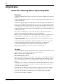 4
4
-
 5
5
-
 6
6
-
 7
7
-
 8
8
-
 9
9
-
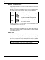 10
10
-
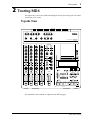 11
11
-
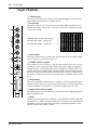 12
12
-
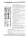 13
13
-
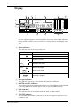 14
14
-
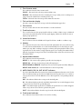 15
15
-
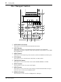 16
16
-
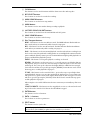 17
17
-
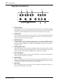 18
18
-
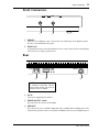 19
19
-
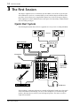 20
20
-
 21
21
-
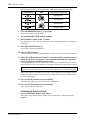 22
22
-
 23
23
-
 24
24
-
 25
25
-
 26
26
-
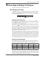 27
27
-
 28
28
-
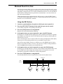 29
29
-
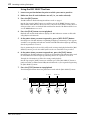 30
30
-
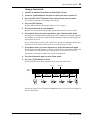 31
31
-
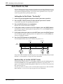 32
32
-
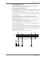 33
33
-
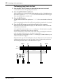 34
34
-
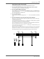 35
35
-
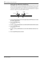 36
36
-
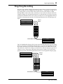 37
37
-
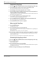 38
38
-
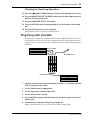 39
39
-
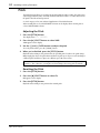 40
40
-
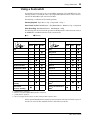 41
41
-
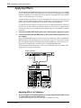 42
42
-
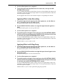 43
43
-
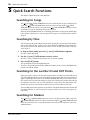 44
44
-
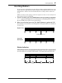 45
45
-
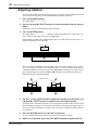 46
46
-
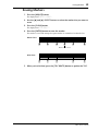 47
47
-
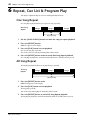 48
48
-
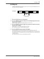 49
49
-
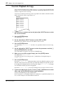 50
50
-
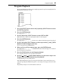 51
51
-
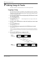 52
52
-
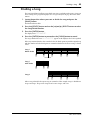 53
53
-
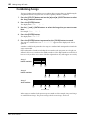 54
54
-
 55
55
-
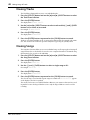 56
56
-
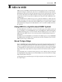 57
57
-
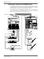 58
58
-
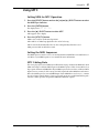 59
59
-
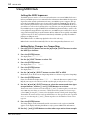 60
60
-
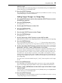 61
61
-
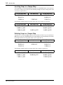 62
62
-
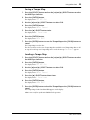 63
63
-
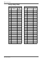 64
64
-
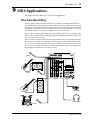 65
65
-
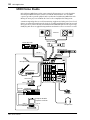 66
66
-
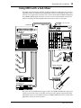 67
67
-
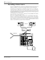 68
68
-
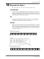 69
69
-
 70
70
-
 71
71
-
 72
72
-
 73
73
-
 74
74
-
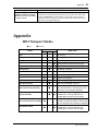 75
75
-
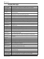 76
76
-
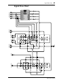 77
77
-
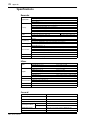 78
78
-
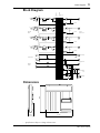 79
79
-
 80
80
-
 81
81
-
 82
82
-
 83
83
-
 84
84
-
 85
85
-
 86
86
-
 87
87
-
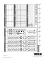 88
88


Yamaha MD4 Manual de usuario
- Categoría
- Instrumentos musicales
- Tipo
- Manual de usuario
- Este manual también es adecuado para
en otros idiomas
- français: Yamaha MD4 Manuel utilisateur
- italiano: Yamaha MD4 Manuale utente
- English: Yamaha MD4 User manual
- Deutsch: Yamaha MD4 Benutzerhandbuch
- русский: Yamaha MD4 Руководство пользователя
- Nederlands: Yamaha MD4 Handleiding
- português: Yamaha MD4 Manual do usuário
- dansk: Yamaha MD4 Brugermanual
- polski: Yamaha MD4 Instrukcja obsługi
- čeština: Yamaha MD4 Uživatelský manuál
- svenska: Yamaha MD4 Användarmanual
- Türkçe: Yamaha MD4 Kullanım kılavuzu
- română: Yamaha MD4 Manual de utilizare
Artículos relacionados
-
Yamaha MD4S Manual de usuario
-
-
-
-
-
-
-
-
-