Peavey CS 3000G Manual de usuario
- Categoría
- Altavoces de la barra de sonido
- Tipo
- Manual de usuario
Este manual también es adecuado para


A
Intended to alert the user to the presence of uninsulated “dangerous voltage” within the product’s enclosure
that may be of sufficient magnitude to constitute a risk of electric shock to persons.
A
Intended to alert the user of the presence of important operating and maintenance (servicing) instructions in the
literature accompanying the product.
CAUTION: Risk of electrical shock
-
DO NOT OPEN!
CAUTION: To reduce the risk of electric shock, do not remove cover. No user serviceable parts inside. Refer servicing to
qualified service personnel.
WARNING: To prevent electrical shock or fire hazard, do not expose this appliance to rain or moisture. Before using this
appliance, read the operating guide for further warnings.
A
Este simbolo tiene el proposito de alertar al usuario de la presencia de “(voltaje) peligroso” que no tiene
aislamiento dentro de la caja
de1
product0 que puede tener una magnitud suficiente coma para constituir riesgo de
corrientazo.
A
Este simbolo tiene el proposito de alertar al usario de la presencia de instruccones importantes sobre la operation
y mantenimiento en la literatura que viene con el producto.
PRECAUCION: Riesgo de corrientazo
-
No
abra.
PRECAUCION: Para disminuir el riesgo de corrientazo, no
abra
la cubierta. No hay piezas adentro que el usario pueda
reparar. Deje todo mantenimiento a
10s
tecnicos calificados.
ADVERTENCIA: Para evitar corrientazos o peligro de incendio, no deje expuesto a la lluvia o humedad este aparato
Antes de usar este aparato, lea mas advertencias en la guia de operation.
A
Ce symbole est utilise pur indiquer
a
l’utilisateur la presence
a
l’interieur
de ce produit de tension non-isolee
dangereuse pouvant etre
d’intensite
suffisante pour constituer un risque de choc Clectrique.
A
Ce symbole est utilise pour indiquer
a
l’utilisateur qu’il
ou
qu’elle trouvera d’importantes instructions sur
l’utilisation et l’entretien (service) de l’appareil dans la litterature accompagnant le produit.
ATTENTION: Risques de
choc
electrique
-
NE PAS OUVRIR!
ATTENTION: Afin de reduire le risque de choc electrique,
ne
pas enlever le couvercle.
11
ne
se trouve
a
l’interieur
aucune piece pouvant
&tre
reparee
par
l’utilisateur.
Confier l’entretien
a
un
personnel qualifie.
AVERTISSEMENT: Afin de prevenir les risques de decharge Clectrique ou de feu, n’exposez pas cet appareil
a
la pluie
ou
a
l’humidite. Avant d’utiliser cet appareil,
lisez les avertissements supplementaires situ& dans le guide.
A
Dieses Symbol
sol1
den Anwender vor unisolierten gefahrlichen Spannungen innerhalb des Gehauses warnen, die
von Ausreichender
Starke
sind,
urn
einen elektrischen Schlag verursachen
zu
konnen.
A
Dieses Symbol
sol1
den Benutzer auf wichtige Instruktionen in der Bedienungsanleitung aufmerksam machen, die
Handhabung und Wartung des Produkts betreffen.
VORSICHT: Risiko
-
Elektrischer Schlag! Nicht offnen!
VORSICHT:
Urn
das Risiko eines elektrischen Schlages
zu
vermeiden, nicht die Abdeckung enfernen. Es befinden
sich
keine Teile darin, die vom Anwender repariert werden konnten. Reparaturen nur von qualifiziertem Fachpersonal
durchfiihren
lassen.
ACHTUNG:
Urn
einen elektrischen Schlag oder Feuergefahr
zu
vermeiden, sollte dieses Gerat nicht dem Regen oder
Feuchtigkeit ausgesetzt werden. Vor Inbetriebnahme unbedingt die Bedienungsanleitung lesen.
2

CS@
3000G Features
l 19” rack-mountable design requiring three-rack spaces
l Automatic two-speed dual fan cooling system
l Separate power transformers/circuit breakers for each channel
l Independent channel thermal/fault protection
l
DDT’”
activation LED and power LED, each channel
l Calibrated/detented input attenuator controls, each channel
l Two recessed, balanced input transformer sockets for PL-2s
l Single XLR and dual phone plug inputs, each channel
l XLR input can be transformer balanced
l Dual phone plug and
5-way
binding post outputs, each channel
l Rear panel
DDT’”
defeat, mode select, and ground lift switches
Peavey Electronics is proud to announce the introduction of a new line of exciting professional power amplifiers. The new
CS-G series is the result of years of research
&
development into a smaller, lighter, compact and more powerful amplifier.
These units operate much more efficiently than contemporary power amp designs, requiring less current from the mains
power plug, producing far less heating. This new technology allows the
CS@
3000G to reliably produce more than 3000 W
RMS into 4 ohms (Bridge Mode) in a three-rack-space unit, at extremely low distortion levels.
These new designs use a new class of operation called “Class BG”. This class uses two levels of power supply “rails,” but
switches between the rails faster and at lower distortion levels than does a typical Class G design. This unit then combines
higher efficiency and lower distortion, and together with our all new Nonsaturating Series Single Emitter Resistor topology
(NSSER), provides awesome performance levels with full power 20
kHz
distortion below
0.04%,
and with slew rates greater
than 40 V&Sec. This technology is called “Dynamic Logic” and is covered by a U.S. Patent (pending).
The following is the new CS 3000G specs:
1000 W RMS into 4 ohms; 1500 W RMS into 2 ohms, per channel
2000 W RMS into 8 ohms; 3000 W RMS into 4 ohms (Bridge mode)
Slew Rate: 40 V/microsecond, Sstereo mode, each channel
Frequency Response: 20 Hz to 20
kHz,
+0.2
dB,
at rated power
Total Harmonic Distortion: Less than
0.04%,
at rated power
Hum and Noise: 100
dB
below rated power, unweighted
The unit is attractively packaged in a rugged, rack-mountable configuration requiring only three rack spaces. Naturally, it has
Peavey’s patented DDT Compression Circuitry, and has a very flexible back panel. The design uses dual, two-speed fan
cooling to provide all the cooling necessary for the two ohm load conditions.
3

Front Panel:
FRONT PANEL FEATURES
CHANNELS A
81
B
INPUT SENSITIVITY (1)
The maximum input gain (minimum sensitivity rating) is achieved at the full clockwise setting, which yields the maximum
mixer/system headroom. A setting of less than full clockwise will yield lower system noise at the expense of mixer/system
headroom. Calibration indicates sensitivity in
dBV
necessary to attain the full available rated output power.
POWER LED (2)
Illuminates when AC power is being supplied to the amp, and the associated channel is operational. If either channel were
to experience fault conditions or to exceed the safe operating temperature limits, then that channel would shut down, and
the associated power LED would cease to illuminate, indicating such conditions exist. Also, whenever the Bridge mode is
selected, the power LED of channel B is defeated (off), just as if there were a fault condition on channel B. This provides
a positive indication that the CS 3000G is configured for Bridge mode.
DDT ACTIVE LED (3)
Illuminates when DDT Compression is taking place in that channel. With the ENABLE/DEFEAT switch in the DEFEAT
position, this LED indicates when clipping distortion is occurring in that channel.
CIRCUIT BREAKERS (4)
A
The CS 3000G uses circuit breakers in place of main fuses. These breakers are provided to limit the current
to the associated power transformer for each channel, and thereby offer protection from overheating and
possible destruction due to fault conditions in the amplifier. The breaker trip current value has been carefully
chosen to allow continuous power output performance, yet still provide adequate protection for the power
A
transformer. Normally, these breakers should not trip unless there is a fault in the amp circuitry that draws
excessive mains current. However, abnormal conditions, such as a short circuit on either or both channels or
continuous operation at overload or clipping (especially into 2 ohm load) will cause the breaker to trip. If this
occurs, turn the power switch off, then simply reset the breaker and correct the cause of the overload.
When tripped, the button on the breaker will be outward nearly
l/2”
and can be reset by pushing inward. A normal reset button
length is about
l/4”.
If this “thermal” type breaker does trip, simply pushing the button back in will reset it, after waiting a brief
period of time to allow it to cool down. REMEMBER, ALWAYS TURN THE POWER OFF BEFORE RESETTING THE
BREAKER. If the breaker trips instantly each time you attempt to reset it, the unit should be taken to a qualified service center
for repair.
POWER SWITCH (5)
Depress to the “I” position to turn on.

Back Panel:
BACK PANEL FEATURES
MAINS POWER SOURCE (6) 120 V products only
The CS 3000G is fitted with a single heavy-duty #lO AWG
3-conductor
line cord and a 30 amp T/P AC plug with
A
a large ground pin. It should be connected to an independent mains circuit capable of supporting at least 30
amps continuously or greater. This is particularly critical for sustained high power operation. If the socket used
does not have a ground pin, a suitable ground lift adaptor should be used and the third wire grounded properly.
Never break off the ground pin on the CS 3000G power amplifier. The use of extension cords should be avoided,
but if necessary, always use a three-wire type with at least a
#lO
AWG wire size. The use of lighter wire will
severelylimitthepowercapabilityofthisamplifierandcouldcausefireorelectricalshock.Alwaysuseaqualified
electrician to install any necessary electrical equipment. To prevent the risk of shock or fire hazard, always be
sure that the amp is properly grounded.
GROUND LIFT SWITCH (7)
This switch is used to disconnect the CS
3000G’s
“signal ground” (both input and output) from the “chassis ground.” Chassis
ground is the chassis itself, which is electrically grounded through the rack mounting screws to the external rack system and
through the mains line cord via the large ground pin to the mains ground. It is often advantageous to “lift” the signal ground
from chassis ground to eliminate a “ground loop” which has caused unwanted ground current in the signal cables between
the external preamp and this power amplifier. Such conditions can create excessive hum levels in the power amplifier output
and render the system useless in low level applications. In this case, “lifting” the ground should solve this hum problem.
Ground lift is selected when the switch is in the right or “LIFT” position. If lifting the ground does not eliminate a particular
hum problem, then we recommend you defeat the ground lift feature.
Note: Using this ground lift feature still leaves the chassis itself grounded electrically through the mains line cord. Having
the chassis grounded avoids any possibility of an electrical shock or a fire hazard. This ground lift feature should never be
confused with the practice of “floating” the large ground pin at the AC mains receptacle to eliminate a ground loop. Floating
the ground pin on any electrical equipment is just asking for trouble!!!
SPEAKER OUTPUTS (8)
A
Each channel
SpeakonO
connector and
5way
binding post speaker output terminals are provided. All these
outputs are in parallel, hence the speaker connection cables can be terminated with
4-pin
Speakona
plugs,
banana plugs, or stripped wires for use in the binding post terminals. Care must be exercised to assure correct
speaker phasing.
5

Regardless of what connections are used, the typical parallel speaker load should always be limited to 2 ohms per channel
or 4 ohms Bridge mode for any application. Operation at loads of 4 ohms per channel or 8 ohms Bridge mode is more
desirable for sustained operation applications due to the fact that the amplifier will run much cooler at this load. Operation
above 4 ohms per channel, and even open circuit conditions can always be considered safe; however, any sustained
operation at loads below 2 ohms could result in temporary channel shut down due to the thermal limits and/or the amp fault
circuits.
LOW-Z INPUT (9)
A conventional
3-pin,
female XLR input jack is provided and may be used as the channel input. When the (PL-2) line balancing
transformer is not used, this XLR input becomes Quasi-Balanced with pin
#3
as the positive input (connecting to the tip of
the
i/4”
input jacks above), pin
#2
as the negative input (connecting to the floating sleeve of the
l/4”
input jacks above), and
pin
#l
going to the internal power amplifier ground. When the (PL-2) line balancing transformer is used, this XLR input
becomes fully Transformer-Balanced (Pin
#3
positive, pin
#2
negative, pin
#l
ground). (See the PL-2 SELECTOR SWITCH
section (next) for details on related settings.)
PL-2 SELECTOR SWITCH (10)
This switch is used in conjunction with the PL-2 transformer to allow the LOW-Z INPUT to function with or without a PL-2
module being inserted in the receptacle. The “out” position of this switch selects the Quasi-Balanced mode of operation for
the LOW-Z INPUT (XLR jack), and routes the input signal directly to the HI-Z INPUT jacks. In this position the HI-Z INPUT
jacks may be used as outputs after the LOW-Z INPUT to allow patching this signal to another input on this amp. Normally,
in this switch position, a (PL-2) transformer is not present (“out”) in the transformer receptacle; however, if one were “in” the
receptacle, the LOW-Z INPUT would still be Quasi-Balanced. It becomes fully Transformer-Balanced only when the “in”
sw,itch
position is selected. Notice this is a very effective means to “test” for the necessity of a line-balancing transformer.
The
“in”
position of the switch routes the signals from the XLR jack through the (PL-2) line-balancing transformer, thereby
selecting the Transformer-Balanced mode of operation for the LOW-Z INPUT. In this position the HI-Z INPUT jacks may be
used as outputs after the line balancing transformer to patch the signal to another input jack on this amplifier or other amps/
equipment.
If the “in” position is selected without a (PL-2) line-balancing transformer “in” the receptacle, the LOW-Z INPUT
will be rendered inoperable.
TRANSFORMER RECEPTACLE (11)
This receptacle only receives the optional (PL-2) line-balancing transformer. When conditions exist that demand the usage
of a Transformer-Balanced XLR Input for either or both channels, then the (PL-2) transformer must be put here, and the
selector switch must be in the “in” position.
MODE SWITCH (12)
This switch is used to select either Stereo or Bridge mode operation. When BRIDGE mode is selected, the channel B LED
power indicator will go out indicating Bridge mode has been selected. Accidental selection of this mode could damage
loudspeakers. Bridge mode will be covered in more detail later in this manual.
HIGH-Z INPUT JACKS (13)
Two parallel (bridged) input jacks are provided for each channel. This allows for one to be used as a conventional input, and
at the same time the other to be used as a “line out” (Y-cord) to connect to another input jack on this amplifier or other amps/
equipment. These
l/4”
jacks are not “chassis grounded” and when used will provide a Quasi-Balanced input capability due
to a unique “ground loop” elimination circuitry associated with the inputs. This feature will normally allow “hum free” operation
when relatively short
l/4”
cable patches are made between the various jacks on this amp and other jacks on various other
equipment that share the same rack with this amplifier, This Quasi-Balanced capability is automatic and cannot be removed
from the system’s circuitry.
DDT COMPRESSION SWITCH (14)
This switch is used to either ENABLE or DEFEAT the DDT compressor. The DDT function will be covered in more detail later
in this manual.
6

INSTALLATION AND CONNECTION
The Peavey
CS
3000G commercial series power amplifier is designed for durability in commercial installations and the
quality of performance required in studio and home applications. The unit is a standard rack-mount configuration,
3-l/2”
high
and is cooled by automatic two-speed internal fans. All of the input and output connections are on the back panel. The front
panel contains LED indicators for power and DDT activation,
detented/calibrated
sensitivity controls, and a mains power
switch.
INDUSTRIAL AND COMMERCIAL INSTALLATIONS
For commercial and other installations, where sustained high power operation is required, the
CS
3000G should be mounted
in a standard
19”
rack. It is not necessary to leave rack space between each amplifier in the stack, since the fan pulls air in
from the rear and exhausts the hot air out of the front. However, an adequate COOL air supply must be provided for the
amplifier when rack-mounted. The internal fan must have a source of air that is not preheated by other equipment. The
amplifierwill start up in “Low Speed” fan operation, and will normallystayat low speed operation unless sustained high power
operating levels occur. Then as the amplifier’s “Heat Sinks” heat up, the automatic thermal sensing circuitry will cause high
speed operation to occur. Depending on signal conditions and amp loading, high speed fan operation may continue or it may
cycle continuously between high and low. This situation is quite normal.
If cooling is inadequate due to preheated air, or a reduction of airflow occurs due to blockage of the amplifier inlet/outlet ports,
or if the amplifier is severely overloaded or short circuited, then the amplifier thermal sensing system may cause temporary
shutdown of that particular channel. This is indicated by the channel power LED on the front panel ceasing to illuminate.
Depending on available cooling air, operation should be restored in that channel relatively quickly, and the power LED will
be illuminated. In any event, corrective action should be taken to determine the cause of the thermal shutdown. If the amplifier
is not severely overloaded or shorted, and air flow is normal in and out of the unit, then steps should be taken to provide a
cooler environment for all the amplifiers. As a general rule, the cooler electronic equipment is operated, the longer its useful
service life.
BRIDGE MODE
The bridge mode on stereo amplifiers is often misunderstood as to the actual operation and usage. In basic terms, when
a two-channel amplifier is operated in the Bridge mode, it is converted into a single-channel unit with a power rating equal
to the sum of both channel’s power ratings, and at a load rating of twice that of the single channel rating. In this case, the
CS
3000G is rated at 1500 W
RMS
per channel into 2 ohms. Thus, the Bridge rating is 3000 W
RMS
into 4 ohms (minimum
load). Bridge mode operation is accomplished by placing the mode switch in the “BRIDGE” position, connecting the load
between the RED binding posts of each channel, and using channel A as the input channel. All the channel B functions as
an input are defeated and they serve no purpose in Bridge mode.
A popular application for Bridge mode operation is to drive sound distribution systems in large public address applications.
In this mode, the
CS
3000G power amplifier can actually drive 70 volt systems directly without using expensive matching
transformers. The real advantage of such an approach is primarily cost.
70 volt distribution systems are very common in applications where rather large numbers of relatively small loudspeakers
are used for background music and paging. Such systems require the use of 70 volt transformers at each loudspeaker.
Another common use for the Bridge mode is in subwoofer applications where very high power levels are required to
adequately reproduce the extreme low frequencies. Such enclosures usually contain 2 or 4 loudspeakers to handle the
power levels involved. For Bridge mode usage, the enclosure impedance must be 4 or 8 ohms; never below 4 ohms! Also
make sure that the enclosure can handle 3000 watts reliably
DDT COMPRESSION
Peavey’s patented DDT compression system enables the sound man to maximize the performance of the amplifier/speaker
combination by preventing the power amp from running out of headroom (clipping). This compression system is activated
by a very unique circuit that senses signal conditions that might overload the amplifier and activates compression (reduces
the amp gain) when clipping is imminent. Threshold of compression, then, is clipping itself and no specific threshold control
is used. This technique effectively utilizes every precious watt available for the power amplifier to reproduce the signal while
at the same time minimizes clipping and distortion, and thus significantly reduces the potential of loudspeaker degradation
and damage. The DDT system is an automatic, hands-off approach to the problem of power amplifier clipping. Since the
CS
3000G power amplifier uses circuit breakers for the over-current protection, the DDT compression system plays even
a more important roll in continuous performance by preventing each channel from clipping and overloading. Continuous
operation at clipping can cause the circuit breaker to trip, but with the DDT activated, this problem is minimized. For this
reason you should always have the DDT compression system enabled.
7

SPECIFICATIONS
Output Power: (typical value)
(@
720
VAC, 60 Hz)
Stereo mode, both channels driven
2 ohms, 1
kHz,
1% THD: 1500 W
RMS
per channel
4 ohms, 1
kHz,
1% THD: 1000 W
RMS
per channel
8 ohms, 1
kHz,
1% THD: 600 W
RMS
per channel
Bridae mode, mono
4 ohms, 1
kHz,
1% THD: 3000 W
RMS
8 ohms, 1
kHz,
1% THD: 2000 W
RMS
Rated Output Power:
(63
120
VAC, 60 Hz)
Stereo mode. both channels driven
4 ohms, 20 Hz to 20
kHz,
0.04% THD: 900 W
RMS
per channel
8 ohms, 20 Hz to 20
kHz,
0.04% THD: 550 W
RMS
per channel
Power Bandwidth: (typical value)
Stereo mode. both channels driven
@
rated power, 4 ohms,
<
0.1% THD: 10 Hz to 40
kHz
Slew Rate: (typical value)
Stereo mode, each channel: 40 volts per
FSec
Bridge mode, mono: 80 volts per
uSec
Total Harmonic Distortion: (typical)
Stereo mode. both channels driven
20 Hz to 20
kHz,
4 ohm rated load:
<
0.04%
Input Sensitivity
&
Impedance:
Input attenuator set
@
FCW
@
rated output power, 4 ohms: 1.5 V
RMS
(0
dBV),
20 k ohms
(+33
dB)
Frequency Response: (typical value)
Stereo mode. both channels driven
+0,-l
dB,
1 W RMS, 4 ohms: 10 Hz to 40
kHz
+O,
-0.3
dB
@
rated output, 4 ohms: 20 Hz to 20
kHz
Damping Factor: (typical value)
Stereo mode, 8 ohms, 1
kHz:
>
300
Hum
&
Noise:
Stereo mode, below rated power. 4 ohms
100
dB,
unweighted
Power Consumption:
Stereo mode, both channels driven
@
rated output power, 4 ohms: 25 A
@
120 V AC,
13A
@
230VAC
Cooling System:
Dual,
2-speed
fans
DDT Compression System:
Switchable with LED
Dimensions
81
Weight:
Height:
5” (8.9 cm)
Width:
19”
(48.3 cm)
Depth:
17”
(43.2 cm)
Weight: 35 Ibs. (15.9 kg)
Three-Rack Space, Class BG, Dual-Rail Design with
NSSER Topology (NSSER: Nonsaturating Series Single
Emitter Resistor).
Patent Pending.
8

1
‘l
lnOZ-ld
.
r’
-
1ndNl
Z-MO1
dW
‘AMOd
lndlil0
3lWN3
C
&
I
mo
I-ld
NOYWdS
NOYWdS
W
13NNWH3
a
13NNWH3
I
1
1
I
dW
‘d3MOd
W
13NNWH3

Wiring Diagrams
I
I
FULL RANGE STEREO
TO
Speakers
from
Mln?,
NOTE.
FO,
transformer
balanced
,nput
,nsta,,
PL’M
2
and
push
Slrl!Ch
to
“I””
posltlon
10

Consulte
10s
diagramas
de1
panel
delantero en la
seccih
de
inglb
de este manual.
Caracteristicas
de1
CS@
3000G
l
Disefiado
para montarse en tres espacios de bastidor de 48.46 cm
l
Sistema doble de enfriamiento con ventilador automatic0 de dos velocidades
l
Transformadores de potencia y cortacircuitos que funcionan por separado para
cada
canal
l
Protection t&mica y de falla independiente por canal
l
Indicadores LED de activation de
DDT’”
y LED de encendido en
cada
canal
l
Controles de pasos fijos de atenuador de entrada calibrados en
cada
canal
l DOS enchufes empotrados de transformador de entrada balanceada para
(transformadores de linea) PL-2
l
Entradas XLR sencillas y entradas dobles para clavija de bayoneta de 6.35 mm en
cada
canal
l
La entrada XLR puede ser balanceada por transformador
l
Salidas para clavijas de bayoneta de 6.35 mm y para clavijas de barra de 5 vias en
cada
canal
l Interruptores para anulacion
de1
DDT”‘,
selector de modo y de levantamiento de
tierra en el tablero trasero
Peavey Electronics se enorgullece en anunciar la presentation de una nueva
linea
de emocionantes amplificadores de
potencia profesionales. La nueva serie CS-G es
el
resultado de
alias
de investigation y desarrollo
para
concebir un
amplificador
mas
pequeiio, ligero,
compact0
y
mas
poderoso. Estas unidades funcionan
mucho
m&i eficientemente que
10s
disehos
de amplificadores de potencia
contemporaneos,
requieren menos corriente de la clavija conectada a la red y
producen
mucho
menos
calor.
Esta nueva tecnologia
le
permite
al
CS@
3000G
producir
confiablemente
mas
de 3000 watts
RMS a 4 ohms (en modo de puente) a niveles extremadamente bajos de
distorsion
en una unidad de tres espacios de
bastidor.
Estos nuevos
disehos
utilizan una nueva
clase
de funcionamiento llamada
qclase
BG)).
Esta
clase
utiliza dos niveles de
ccrieles,,
de
alimentacion
de corriente, pero
cambia
entre
10s
rieles
m&s
rapidamente y a
menores
niveles de
distorsion
que
un tipico disefio de
clase
G. Por lo
tanto,
esta unidad
combina
mayor eficiencia y
menor
distorsion,
y conjuntamente con
nuestra totalmente nueva topologia de resistor emisor sencillo de serie no saturante (NSSER), proporciona maravillosos
niveles de rendimiento a 20
kHz
de potencia
completa
por debajo del
0.04%,
y con velocidades de torsion
mayores
de
40
V/uSeg.
Esta tecnologia se llama
((logica
dinamica~~
y
esta
protegida por una patente de
10s
Estados Unidos (en tramite).
A continuation,
las
especificaciones del CS 3000G:
1000 W RMS a 4 ohms; 3000 W RMS a 2 ohms, por canal
2000 W RMS a 8 ohms; 1500 W RMS a 4 ohms (modo de puente)
Velocidad de torsion: 40
V/microsegundo,
modo estereofonico,
cada
canal
Respuesta de frecuencia: 20 Hz a 20
kHz,
_+0,2
dB
a la potencia clasificada
Distorsion
armonica
total: Menos de
0,04%,
a la potencia clasificada
Zumbido grave y ruido: 100
dB
debajo de la potencia clasificada, sin peso
11

La unidad
esta
atractivamente empacada en una
robusta
configuration
para
montar en bastidor que requiere de solo tres
espacios. Naturalmente, tiene
10s
circuitos
de
compresion
DDT patentados por Peavey y un tablero trasero muy flexible.
El
disefio
usa
doble ventilador de dos velocidades
para
proporcionar
todo
el
enfriamiento necesario
para
las
condiciones
de calentamiento de la
carga
de 2 ohms.
FUNCIONES DEL PANEL FRONTAL
CANALES A Y B
INPUT SENSITIVITY (Sensibilidad de entrada) (1)
La ganancia maxima de entrada (clasificacion minima de sensibilidad) se logra con un ajuste totalmente a la derecha,
el
cual
proporciona la maxima altura a la mezcladora o
el
sistema. Un ajuste
menor
del registrado totalmente a la derecha
ofrecera
menor
ruido de sistema en detriment0 de la altura de la mezcladora o
el
sistema. La calibration
indica
la sensibilidad
en
dBV
necesaria
para
lograr la maxima
salida
clasificada disponible.
POWER LED
(Indicador
LED de encendido) (2)
Se enciende cuando se
alimenta
corriente a la unidad y
el
canal asociado
esta
en funcionamiento. Si
alguno
de
10s
canales
experimenta una
condicion
de
falla
o excede
10s
limites
de temperatura de funcionamiento, entonces dicho canal se apagara
y
el
indicador
LED asociado se apagara, indicando que
existen
tales condiciones.
Tambien,
siempre que se seleccione
el
modo de puente,
el
indicador
LED del canal B se anula (se apaga), exactamente igual que si hubiera una
condicion
de
falla
en
el
canal B. Esto proporciona una indication positiva de que
el
CS 3000G
esta
configurado
para
el
modo de puente.
DDT ACTIVE LED
(Indicador
LED de
activacih
del DDT) (3)
Se enciende cuando
toma
lugar la
compresion
DDT en ese canal. Con
el
interruptor
HABILITAR/ANULAR
en la position
ANULAR, este
indicador
LED muestra cuando ocurre un recorte por
distorsion
en ese canal.
CIRCUIT BREAKERS (Cortacircuitos) (4)
A
Este cortacircuitos se proporciona
para
limitar la corriente al transformador de potencia asociado y
para
protegerlo
contra sobrecalentamiento y una posible destruction
debida
acondiciones de
falla
en
el
amplificador.
Los valores de disparo de la corriente se han elegidos cuidadosamente
para
permitir un rendimiento de
salida
de potencia continua, y
aun
asi,
proporcionar una
protection
adecuada al transformador de potencia.
A
Normalmente, estos cortacircuitos no
deben
dispararse a menos que
exista
una condition de
falla
en
10s
circuitos
del amplificador que exija una corriente excesiva de la red. Sin embargo,
las
condiciones anormales
coma
un cortocircuito en
alguno
de
10s
canales
o en ambos, o un funcionamiento
continua
con sobrecarga o
con recortes por sobrecarga (especialmente en la
carga
a 2 ohms)
hara
que
el
cortacircuito se dispare. Si esto
ocurre, apague
el
interruptor de encendido y entonces simplemente restablezca
el
cortacircuito y corrija la
causa
de la sobrecarga.
Cuando
este
disparado,
el
baton
se extendera
casi
12.70 mm, y se puede restablecer oprimiendolo hacia adentro. El
largo
normal del
baton
de restablecimiento es de alrededor de 6.35 mm. Si este cortacircuito de tipo
4ermico~~
se dispara, con
solo oprimir
el
baton
se restablecera
despues
de esperar un breve
period0
de tiempo
para
permitir que se enfrie.
Recuerde:
apague siempre el interruptor de encendido antes de
resfablecer
el
cortacircuito. Si
el
cortacircuito se dispara
instantaneamente
cada
vez que intente restablecerlo, entonces debe llevar la unidad a un centro de servicio calificado
para
que sea reparada.
POWER SWITCH (Interruptor de encendido) (5)
Oprimalo a la position
~~1~~
para
encender.
12

Panel Trasero:
FUNCIONES DEL PANEL TRASERO
AC LINE CORD SOCKET (Tomacorriente para
el
cable de corriente) (6)
A
Se suministra
para
enchufar
el
cable de corriente.
GROUND LIFT SWITCH (Interruptor levantamiento de tierra) (7)
Este interruptor se
usa
para
desconectar la
<<tierra
de
serial))
del CS 3000G
(tanto
de entrada
coma
de
salida)
de la
cctierra
del
chasiw.
La tierra del chasis es
el
chasis mismo,
el
cual
esta
conectado a tierra electricamente a traves de
10s
tornillos
de montaje al sistema externo del bastidor; y a traves del cable de corriente por medio de la gran varilla de tierra a la tierra
de la red de corriente. A
menudo
es ventajoso
-levantarbb
la tierra de
sefial
de la tierra de
chaslis
para
eliminar un -circuit0
de
tierra,,,
el
cual
ha causado una corriente de tierra indeseada en
10s
cables de seiial entre
el
preamplificador externo y
este amplificador de potencia. Tales condiciones pueden
causar
niveles excesivamente altos de zumbido grave en la
salida
del amplificador de potencia, y hater
inutil
el
sistema
para
aplicaciones de bajo nivel. En este
camso,
cclevantar>>
la tierra debe
resolver
el
problema
de zumbido grave. El levantamiento de tierra se selecciona cuando
el
interruptor
esta
a la derecha o
en la position
=LEVANTAR,,.
Si levantar la tierra no elimina un
problema
de zumbido grave en particular, recomendamos
que anule la
funcion
de levantamiento de tierra.
Nota: El uso de esta
funcion
de levantamiento de tierra,
sun
deja al chasis mismo conectado
electricamente
a tierra a traves
del cable de corriente. Al tener
el
chasis conectado a tierra se evita cualquier posibilidad de un choque
electrico
o un peligro
de incendio. Esta
funcion
de levantamiento de tierra no debe confundirse con la
practica
de
c<anular,,
la gran varilla de tierra
en
el
enchufe de CA de la red de corriente
para
eliminar
el
circuit0
de tierra. Anular la varilla de tierra de cualquier
equip0
electrico,
ii ies solo
buscar
problemas!!!
SPEAKER OUTPUTS (Salidas de altavoces) (8)
A
D
OS
terminales de
salida
tanto
para
clavijas de
Speakon@.
Todas estas salidas
estan
en paralelo, por esto,
10s
cables de
conexion
de
10s
altavoces pueden terminar en clavijas de quatro
contactos
de SpeakoP, clavijas
((banana,,
o cables desnudos
para
usarse en
las
terminales de
barra.
Debe tenerse cuidado
para
asegurar la
correcta
polaridad de
10s
altavoces.
Sin importar
que
conexiones se
usen,
en cualquier
aplicacion
la
carga
tipica en paralelo siempre debe limitarse a 2 ohms
por canal 6 4 ohms en modo de puente. En aplicaciones de funcionamiento sostenido, es
mas
deseable
el
funcionamiento
a
cargas
de 4 ohms por canal u 8 ohms en modo de puente,
debido
al
hecho
de que
el
amplificador funcionara a
menor
temperatura a esta
carga.
Siempre puede considerarse seguro
el
funcionamiento a
mas
de 4 ohms por canal, e incluso
las
condiciones de
circuit0
abierto; sin embargo, cualquier funcionamiento a
cargas
por debajo de 2 ohms puede dar
coma
resultado un apagado temporal del canal
debido
a
10s
limites
termicos
y/o
10s
circuitos
de
falla
del amplificador.
13

LOW-Z INPUT (Entrada de baja impedancia) (9)
Se proporciona un enchufe de entrada XLR
hembra
de tres varillas
conventional
y puede usarse
coma
el
canal de entrada.
Cuando no se
usa
el
transformador de balance de
linea
(PL-2),
esta entrada XLR se convierte en cuasibalanceada, con
la varilla
N”3
coma
entrada positiva (conectada a la
punta
del enchufe
para
clavija de
bayoneta
de 6.35 mm de arriba), la
varilla
N”2
coma
entrada negativa (conectada a la mangaflotante
del
enchufe
para
clavija de
bayoneta
de 6.35 mm de arriba)
y la varilla
N”1
conectada a la tierra
interna
del amplificador de potencia. Cuando se
usa
el
transformador de
linea
(PL-2),
esta entrada XLR se convierte completamente en balanceada por transformador (Varilla
N”3
positivo, varilla
N-2
negativo
y varilla
N”1
tierra). (Vea
10s
detalles sobre ajustes
10s
relativos en la section INTERRUPTOR SELECTOR PL-2 [a
continuation].)
PL-2 SELECTOR SWITCH (Interruptor selector PL-2) (10)
Este interruptor se
usa
conjuntamente con
el
transformador PL-2
para
permitir que funcione la ENTRADA DE BAJA
IMPEDANCIA con o sin un
module
PL-2 insertado en
el
receptaculo. La position
((fuera))
de este interruptor, selecciona
el
modo de funcionamiento cuasibalanceado
para
la ENTRADA DE BAJA IMPEDANCIA (enchufe XLR), y dirige la
senal
de entrada directamente a
10s
enchufes de ALTA IMPEDANCIA. En esta position,
10s
enchufes de ALTA IMPEDANCIA
pueden usarse
coma
salidas
despues
de la ENTRADA DE BAJA IMPEDANCIA
para
permitir la
conexion
temporal de la
serial a otra entrada de este amplificador. Normalmente, en esta position del interruptor, no hay un transformador (PL-2)
presente
(ccfuera,,)
en
el
receptaculo paratransformador; no obstante, si hubiera uno
<<dentro))
del receptaculo, la ENTRADA
DE BAJA IMPEDANCIA
aun
estaria cuasibalanceada. Se convierte en totalmente balanceada por transformador solamente
cuando se selecciona la position
ccdentro,,
del interruptor. Tome
nota
de que
esta
es una
manera
muy efectiva de
<(probar,,
si se necesita un transformador de
linea.
La position
((dentro,,
del interruptor dirige
las
senales
del enchufe XLR a traves
del transformador de balance de
linea
(PL-2),
y por lo mismo, selecciona
el
modo de funcionamiento balanceado por
transformador
para
la ENTRADA DE BAJA IMPEDANCIA. En esta position,
10s
enchufes de ALTA IMPEDANCIA pueden
usarse
coma
salidas despues del transformador de balance de
linea
para
conectar temporalmente la serial a otro enchufe
de este amplificador u otros amplificadores o equipo. Si se selecciona la position
=dentro))
sin un transformador de balance
de
linea
(PL-2)
((dentro),
del receptaculo, la ENTRADA DE BAJA IMPEDANCIA
sera
anulada.
TRANSFORMER RECEPTACLE (Receptaculo de transformador) (11)
Este receptaculo solamente acepta
el
transformador de balance de
linea
(PL-2)
optional.
Cuando
existen
condiciones que
exigen
el
uso de una entrada XLR Balanceada por transformador
para
cualquiera de
10s
dos
canales
o ambos, entonces
el
transformador (PL-2) debe ponerse aqui y
el
selector debe estar en la position
((dentro,,.
MODE SWITCH (Interruptor de modo) (12)
Este interruptor se
usa
para
seleccionar ya sea
el
modo Estereofonico o
el
modo de Puente. Cuando se selecciona
el
modo
de PUENTE,
el
indicador LED del canal B se
apagara,
indicando que se ha seleccionado
el
modo de PUENTE. La selection
accidental de este modo podria
danar
10s
altavoces. Cubriremos
el
modo de puente
m8s
adelante en este manual.
HIGH-Z INPUT JACKS (Enchufes de entrada de alta impedancia) (13)
Se proporcionan dos enchufes de entrada en paralelo (puenteados). Esto
permite
que uno se use
coma
entrada
conventional y, al mismo tiempo,
el
otro se use
coma
<salida
de
linea))
(cable
<<Y,))
para
conectar a otro enchufe de entrada
en este amplificador u otros amplificadores o equipo. Estos enchufes
para
clavija de
bayoneta
de 6.35 mm no estan
cconectados
a tierra de chasiw, y cuando se
usan
proporcionan una capacidad de entrada Cuasibalanceada
debido
a un
singular
circuit0
eliminador de
<circuit0
de
tierra))
asociado a
las
entradas. Normalmente, esta caracteristica permitira un
funcionamiento
((sin
zumbido
grave’,
cuando se
hagan
conexiones temporales con cables de 6.35 mm relativamente cortos
entre
10s
varios enchufes de este amplificador y
10s
otros enchufes de
10s
equipos varios que comparten
el
mismo bastidor
con este amplificador. Esta capacidad Cuasibalanceada es automatica y no puede retirarse del
circuit0
del sistema.
DDT COMPRESSION SWITCH (Interruptor de la compresion DDT) (14)
Este interruptor se
usa
ya sea
para
HABILITAR o ANULAR
el
compresor
DDT. Cubriremos la
funcion
DDT en mayor detalle
mas
adelante en este manual.
INSTALACIGN Y CONEXIGN
El amplificador de potencia de la serie
comercial
Peavey CS 3000G
esta
disenado
para
durabilidad en instalaciones
comerciales y calidad de
desempeno
requeridos en aplicaciones de estudio y
el
hogar. La unidad tiene una configuration
estandar de montaje en bastidor de 8.89 cm de altura y es enfriada por ventiladores internos
automaticos
de dos
velocidades. Todas
las
conexiones de entrada y
salida
estan
en
el
tablero trasero. El tablero frontal contiene indicadores
LED de encendido y activation del DDT,
controles
de pasos fijos calibrados de sensibilidad y un interruptor de encendido.
.
14

INSTALACdN
INDUSTRIAL Y COMERCIAL
Para
instalaciones comerciales o de otras en
las
que se requiera un funcionamiento sostenido de alta potencia,
el
CS 3000G
debe instalarse en un bastidor estandar de 48.26 cm. No se requiere dejar un espacio entre
cada
amplificador de la pila,
ya que
el
ventilador absorbe
aire
de la parte trasera y expele
el
aire
caliente por
el
frente. Sin embargo, debe proporcionarse
a
cada
amplificador una fuente de
aire
((FRESCO)).
El ventilador
interno
debe tener una fuente de
aire
que no
haya
sido
precalentado por otro equipo. El amplificador comenzara a funcionar con
el
ventilador en
<cbaja
velocidad-,
y normalmente
seguira en baja velocidad a menos que ocurra un funcionamiento a niveles de alta potencia sostenida. Entonces, al
calentarse
10s
((Disipadores
de
calorb,
del amplificador,
el
circuit0
sensor termico causara que ocurra un funcionamiento a
alta velocidad. Dependiendo de
las
condiciones de la serial y de la
carga
del amplificador,
el
funcionamiento del ventilador
a alta velocidad puede
continuar
o seguir un ciclo
continua
entre
alta
y baja. Esta situation es bastante normal.
Si
el
enfriamiento es inadecuado
debido
al
aire
precalentado, o una reduction del
flujo
de
aire
debido
al bloqueo de
las
ventilas de entrada o
salida
del amplificador; o
si
el
amplificador ha sido seriamente sobrecargado o se ha causado un
cortocircuito,
el
sistema sensor termico de la unidad puede
causar
un apagado termico temporal de tal canal en particular.
Esto
sera
indicado al apagarse
el
indicador
LED del tablero frontal. Dependiendo de la disponibilidad de
aire
para
enfriamiento,
el
funcionamiento
debera
restablecerse rapidamente, y se encendera
el
indicador
LED. En cualquier
case,
se
deben
tomar
las
medidas
correctivas
para
determinar la
causa
del apagado termico. Si
el
amplificador no
esta
seriamente
sobrecargado ni tiene un cortocircuito, y
el
flujo
de
aire
es normal hacia adentro y hacia afuera de la unidad, entonces
deben
tomarse
las
medidas necesarias
para
proporcionarles un ambiente
mas
fresco a todos
10s
amplificadores. Como regla
general, mientras
mas
frio funcione
el
equip0
electrico,
mas
larga
sera
su vida de servicio
util.
MOD0
DE PUENTE
El modo de puente en amplificadores
estereofonicos
es a
menudo
malentendido en
cuanto
a su uso y operation reales.
En terminos
claros,
cuando un amplificador de dos
canales
funciona en
el
modo de PUENTE,
este
se convierte en una
unidad de canal
unico,
con una
clasificacion
de potencia equivalente a la
suma
de la
clasificacion
de potencia de ambos
canales,
y a una
clasificacion
de
carga
equivalente al doble de la clasificacion del canal sencillo. En este
case,
el
CS 3000G
esta
clasificado a 1500 W RMS por canal a 2 ohms. De esta
manera,
la
clasificacion
de puente es de 3000 W RMS a 4 ohms
(carga
minima). El funcionamiento en modo de puente se logra colocando
el
interruptor de modo en la
position
-PUENTEbb,
conectando la
carga
entre
10s
enchufes
para
clavija de
barras
ROJOS de
cada
canal, y
usando
el
canal A
coma
el
canal
de entrada. Todas
las
funciones del canal B
coma
entrada se anulan y no tienen
ningun
proposito
en modo de puente.
Una
aplicacion
comun
para
el
modo de puente es
para
impulsar un sistema de distribution de
sonido
en grandes
aplicaciones de voceo. En este modo,
el
amplificadorde potencia CS 3000G puede en realidad impulsarsistemas de 70 volts
directamente, sin necesidad de usar costosos transformadores de equivalencia. La ventaja real de tal metodo es
principalmente
el
costo.
Los sistemas de distribution de
sonido
de 70 volts son muy
comunes
en aplicaciones es
las
que cantidades
mas
bien
grandes de relativamente
pequenos
altavoces se
usan
para
musica
de fondo y voceo. Tales sistemas requieren
el
uso de
transformadores de 70 volts en
cada
altavoz. Otro uso
comun
del modo de Puente es en aplicaciones de altavoces
para
sonidos supergraves, donde se requieren altos niveles de potencia
para
reproducir
adecuadamente
las
frecuencias
extremadamente bajas. Tales cajas
acusticas
normalmente contienen 2 6 4 altavoces
para
soportar
10s
altos niveles de
potencia implicados. La impedancia de la
caja
acustica
debe ser de 4 u 8 ohms
para
usar
el
modo de puente.
i
Nunca menos
de 4 ohms! Tambien, asegurese de que la
caja
acustica
pueda sopor-tar 3000 watts confiablemente.
COMPRESldN
DDT
El sistema de
compresion
patentado DDT de Peavey
permite
al ingeniero de
sonido
maximizar
el
rendimiento del sistema
de amplificador y altavoces al prevenir que
el
amplificador agote su altura (recorte por sobrecarga). Este sistema de
compresion
es activado por un muy especial
circuit0
que percibe
las
condiciones de
senal
que
podrian
sobrecargar
el
amplificador y
activa
la
compresion
(reduce la ganancia del amplificador) cuando es inminente un recorte por sobrecarga.
Entonces
el
umbra1
de
compresion
es
el
recorte mismo y no se
usa
un control de
umbra1
especifico. Esta tecnica utiliza
cada
uno de
10s
muy preciados watts disponibles
para
el
amplificador de potencia al mismo tiempo que minimiza
el
recorte por
sobrecarga y la distorsion, y de esta
manera
reduce significativamente
el
potential de
degradation
y
danos
a
10s
altavoces.
El sistema DDT es un metodo
automatic0
y sin necesidad de ajuste manual
para
enfrentar
el
problema
de recorte por
sobrecarga del amplificador de potencia. Ya que
el
amplificador de potencia CS 3000G
usa
cortacircuitos
coma
protection
de elevation de la corriente,
el
sistema DDT de
compresion
juega un papel
mas
importante
aun
en
el
desempeno
continua
al evitar que
cada
canal sea recortado por sobrecarga o se sobrecargue. El funcionamiento continua al nivel de recorte por
sobrecarga puede causar que
10s
cortacircuitos se disparen, pero con
el
DDT activado, este
problema
se minimiza. Por esta
razon,
usted
debe tener siempre activado
el
sistema de
compresion
DDT.
15

Veuillez-vous refkrer au
<<
front panel
>>
art
situ6
dans la section en langue anglaise de ce manuel.
Caracthistiques
du
CS@
3000G
l
Montage en baie de
46,36
cm (19
PO.)
exigeant tres espaces rack
l
Systeme de refroidissement automatique
avec
double ventilateur
a
deux vitesses
l
Transformateurs/disjoncteurs independants au niveau de chaque canal
.
Protection independante
thermique/dCfaillance
des canaux
DEL d’activation du
DDT’”
et DEL d’alimentation pour chaque canal
Bouton de reglage d’attenuateur d’entree calibres/a arret pour chaque canal
Deux emplacements encastres pour transformateurs d’entree
Cquilibree
destines
au PL-2
Entrees pour fiche XLR et fiche telephonique double sur chaque canal
L’entree XLR peut
Gtre
Cquilibree
par l’intermediaire du transformateur
Sorties pour fiche telephonique double et borne de connexion
a
5 voies sue
chaque canal
Commutateurs de d&activation du
DDTrM,
de selection de mode et de
separation
de
terre sur le panneau arriere
Peavey Electronics est fier d’annoncer la sortie de sa nouvelle gamme d’amplificateurs professionnels. La nouvelle
serie
CS-G est
le
fruit d’annees de recherches, et
le
resultat
est un amplificateur plus petit, plus
leger,
plus compact et plus
puissant. Les amplificateurs de cette
serie
fonctionnent plus efficacement que ceux actuellement sur
le
marche
car
ils
exigent une alimentation courant moins importante tout en produisant
beaucoup
moins de chaleur. Cette nouvelle
technologie
permet
au
C!9
3000G de produire fiablement plus de 3000 W RMS en 4 ohms (mode pont) a des niveaux de
distorsion minimes, et ce dans un
espace
de
tres
baies seulement.
Ces nouveauxamplificateurs appartiennent
a
une nouvelleclasse defonctionnement,
appelee
((
Classe BG
>a.
Celle-ci
utilise
deux niveaux d’acheminement d’alimentation electrique,
mais
le
passage de l’un
a
I’autre se fait plus vite et
avec
moins de
distorsion que dans
le
cas des amplificateurs
concus
sur
le
modele
Classe G classique. Le
resultat
est un appareil alliant
une plus grande efficacite et une distorsion plus faible, lesquelles,
combinees
a
notre topologie NSSER (Nonsaturating
Series Single Emitter Resistor),
offrent
des niveaux de performance
inegales
avec
une distorsion inferieure a
0,04
%
a une
puissance
maximale
de 20
kHz
et des taux de balayage de la tension de sortie superieurs
a
40
V/frSec.
Cette
technologie
s’appelle
((
Dynamic Logic
))
(Logique dynamique), et fait I’objet d’un brevet americain (en attente).
Les caracteristiques techniques du nouveau CS 3000G sont
les
suivantes
:
1000 W RMS en 4 ohms, 1500 W RMS en 2 ohms, par canal
2000 W RMS en 8 ohms, 3000 W RMS en 4 ohms (mode pont)
Vitesse de balayage de la tension de sortie
:
40
V/microseconde
en mode stereo, par canal
Reponse
en
frequence
:
de 20 Hz a 20
kHz,
+
0,2
dB,
a la puissance de fonctionnement
Distorsion harmonique
totale
:
inferieure a
0,04
%,
a
la puissance de fonctionnement
Ronflement et bruit
:
100
dB
en dessous de la puissance de fonctionnement, non
pond&e
Cet appareil se presente
sous
forme
d’un montage en baies robuste n’exigeant que
tres
espaces
rack. II est
bien-sQr
equipe
des circuits de compression
brevet&
DDT de Peavey Electronics, et
comporte
un panneau arriere
tres
versatile. Son
systeme
de refroidissement a ventilateur double a deux vitesses
fournit
le
refroidissement necessaire aux chargements de
2 ohms.
16

CARACT~RISTIQUES
DU PANNEAU AVANT
CANAUX A ET
6
INPUT SENSITIVITY (Bouton de reglage de sensibilite de I’entrke) (1)
Un gain
d’entree
maximum (taux de sensibilite minimum) est obtenu en tournant ce
bouton
a
fond dans
le
sens des aiguilles
d’une montre, ce qui produit une marge
maximale
pour
le
melangeurkysteme. Si
le
bouton
n’est pas tourne a fond dans
le
sens horaire,
le
systeme
emet
moins de bruit,
mais
la marge
reservee
au
melangeur/systeme
s’en trouve reduite.
L’etalonnage indique la sensibilite en
dBV
necessaire
a
I’obtention de la puissance de sortie maximale.
POWER LED (DEL d’alimentation) (2)
Cette DEL est
illuminee
lorsque I’amplificateur est
alimente
en courant alternatif et que
le
canal associe est operationnel.
Si
I’un
des deux canaux presente une defaillance ou excede la temperature limite pour un fonctionnement sans danger,
il
est mis hors fonctionnement et la DEL correspondante s’eteint, ce qui indique la presence d’un de ces deux problemes. Par
ailleurs, lorsque
le
mode pont est
selectionne,
la DEL d’alimentation du canal B est
desactivee
(off),
comme
s’il
existait une
defaillance sur ce canal. Cela
permet
de s’assurer que
le
CS 3000G est configure en mode pont.
DDT ACTIVE LED (DEL d’activation du DDT) (3)
Cette DEL est
illuminee
lorsque la compression DDT est
activee
sur ce canal. Lorsque I’interrupteur ENABLE/DEFEAT
(Activer/Desactiver)
est sur la position DEFEAT, cette DEL
signale
qu’une distorsion de
Crete
se produit sur ce canal.
CIRCUIT BREAKERS (Disjoncteurs) (4)
Ce disjoncteur limite
le
courant
recu
par
le
transformateur et protege ainsi celui-ci d’une surchauffe et d’une
A
destruction
eventuelle
a la suite d’une defaillance de I’amplificateur. La valeur de declenchement de ce
disjoncteur a
ete
soigneusement
etudiee
de maniere a permettre une alimentation de sortie
continuelle
tout en
protegeant
le
transformateur. Normalement, ce type de disjoncteur ne se declenche que s’il existe une
A
defaillance des circuits de I’amplificateur faisant passer un courant secteur excessif. Toutefois, des conditions
anormales, telles qu’un court-circuit d’un ou des deux canaux ou un fonctionnement
continue1
avec
surcharge
ou
ecretage
(particulierement en charge de 2 ohms) peuvent declencher
le
disjoncteur. Dans ce cas,
il
convient
de mettre I’appareil hors tension, de remettre
le
disjoncteur dans sa position initiale et
d’eliminer
la cause du
declenchement.
Lorsque
le
disjoncteur se declenche, son
bouton
est
sorti
d’environ
12,7
mm
(l/2
PO.)
et
il
suffit de I’enfoncer pour
le
remettre
en place. Normalement, ce
bouton
depasse d’environ
6,35
mm
(l/4
PO.).
Si ce type de disjoncteur
((
thermique
a’
se
declenche,
il
suffit d’enfoncer son
bouton
pour
le
remettre dans sa position initiale
apres
avoir attendu un instant qu’il
ref roidisse.
N’oobliezpas de
toujoors
mettre I’appareil hors tension avant de remettre
le
disjoncteur dans sa position
initiale.
Si
le
disjoncteur se
declenche
a
chaque tentative de remise a
l’etat
initial, I’appareil
doit
etre
porte
a
un
technicien
qualifie
pour reparation.
POWER SWITCH (Commutateur marche-arrQt) (5)
L’enfoncer en position
((
I
>>
pour mettre I’amplificateur
sous
tension.
17

Panneau
Arrkre
:
CARACTERISTIQUES
DU PANNEAU ARRIlkRE
AC LINE CORD SOCKET (Prise pour cdble d’alimentation) (6)
A
Prise de branchement du cordon d’alimentation CA detachable.
GROUND LIFT SWITCH (Commutateur de separation de terre) (7)
Ce commutateur set-t a deconnecter la
<<
terre signal
))
de I’amplificateur (a
I’entree
et a la sortie) de la
<c
terre chassis
)).
La
terre chassis est
le
chassis
lui-meme,
qui est mis
a
la terre par I’intermediaire des vis de I’armoire externe et du cordon
d’alimentation secteur via la grosse fiche de prise de terre secteur. II est souvent necessaire de
<<
separer
))
la terre signal
de la terre chassis pour
eliminer
une boucle terre qui risque de provoquer un courant de terre indesirable dans les cables
de signaux
situ&
entre
le
preamplificateur et I’amplificateur
lui-meme.
En effet,
si
cela
se produit, un ronflement excessif
est
emis
a la sortie du preamplificateur, ce qui rend
le
systeme inoperable
a
faible volume. Ce
probleme
de ronflement est
elimine
par la separation de terre, qui est activee lorsque
le
commutateur est en position de droite (LIFT). Si toutefois
le
probleme
persiste,
il
est
conseille
de ne pas utiliser la separation de terre.
Remarque
:
Meme
lorsque la separation de terre est
utilisee,
le
chassis reste mis
a
la terre par I’intermediaire du cordon
d’alimentation secteur. La mise
a
la terre du chassis
permet
d’eviter tout risque de
choc
electrique ou d’incendie. La
separation de terre ne
doit
en aucun cas
etre
confuse
avec
cc
I’isolation de la terre
))
de la grosse fiche de terre de la prise
murale destinee
a
eliminer
les boucles de terre. Une
telle
isolation d’un equipement electrique est en effet
tres
dangereuse.
SPEAKER OUTPUTS (Sorties des haut-parleurs) (8)
A
Les fiches du
Speakon@
et terminaux de sortie des haut-parleurs. Toutes ces sorties sont en
parallele,
ce qui
permet
de raccorder
les
cables de connexion des haut-parleurs
avec
des fiches a quatre clavette du
Speakon@,
des fiches bananes ou des fils denudes de raccordement aux terminaux des bornes de connexion. II est
necessaire de prendre des precautions pour assurer une mise en phase
correcte
des haut-parleurs.
Quelle que
soit
la methode de raccordement employee, la charge en
parallele
typique des haut-parleurs ne
doit
jamais
depasser 2 ohms par canal ou 4 ohms en mode pont. Une exploitation
a
4 ohms par canal ou 8 ohms en mode pont est
recommandee en cas de fonctionnement
continu,
car
elle
permet
a I’amplificateur de moins
chauffer
a cette charge.
L’exploitation a4 ohms ou plus par canal, et
meme
I’exploitation en circuit ouvert ne posent en general aucun risque, toutefois
une exploitation
a
moins de 2 ohms peut entrainer
I’arret
temporaire des canaux
dO
aux limites thermiques
et/au
a la
defaillance
des circuits de I’amplificateur.
18

LOW-Z INPUT (EntrBe Low-Z) (9)
Un jack d’entree XLR
femelle
ordinaire
a
trois
broches
est fourni et peut servir d’entree de canal. Lorsque
le
transformateur
d’equilibrage des circuits (PL-2) n’est pas
utilise,
cette entree XLR devient quasi equilibree
:
la broche No. 3 sert d’entree
positive (assurant la connexion
avec
I’extremite
des jacks de
6,35
mm
(l/4
PO.)
ci-dessus), la broche No. 2 d’entree negative
(assurant la connexion
avec
le
manchon flottant des jacks de
6,35
mm
(l/4
PO.)
ci-dessus), et la broche No. 1 assure la
connexion a la terre de I’amplificateur interne. Si
le
transformateur d’equilibrage des circuits (PL-2) est
utilise,
cette entree
devient equilibree par
le
transformateur (la broche No. 3 est I’entree positive, la broche No. 2 I’entree negative, et la broche
No.1 la terre). Pour de plus
amples
details sur les
reglages
appropries, se reporter a la section suivante, Commutateur de
selection PL-2.
PL-2 SELECTOR SWITCH (Commutateur de
st5lection
PL-2) (10)
Ce commutateur s’utilise
avec
le
transformateur PL-2 pour permettre a I’ENTREE LOW-Z de fonctionner
avec
ou sans
I’insertion d’un module PL-2 dans
le
receptacle. La position sortie
(cc
out
aa)
de ce commutateur
permet
de selectionner un
mode d’exploitation quasi
equilibre
pour I’ENTREE LOW-Z (jack XLR), et
achemine
directement
le
signal vers les jacks
d’ENTREE
HI-Z. Dans cette position,
ceux-ci
peuvent servirde sorties
apres
I’ENTREE LOW-Z pour permettre la connexion
de ce signal
avec
une autre entree de I’amplificateur. Normalement, quand
le
commutateur est dans cette position,
le
transformateur PL-2 ne
doit
pas
etre
ins&e dans
le
receptacle du transformateur. Toutefois, s’il I’est, I’ENTREE LOW-Z est
tout de
meme
quasi equilibree.
Elle
ne devient equilibree par
le
transformateur que lorsque
le
commutateur est en position
entree
(cc
in
))).
Cela
permet
en effet de verifier la
necessite
d’utiliser
le
transformateur d’equilibrage des circuits. La position
<<
in
>>
du commutateur
achemine
les signaux en provenance du jack XLR vers
le
transformateur d’equilibrage des circuits
(PL-2),
selectionnant ainsi
le
mode d’exploitation equilibre par
le
transformateur pour I’ENTREE LOW-Z. Les jacks
d’ENTREE
HI-Z peuvent alorsservirdesorties
apres
le
transformateurd’equilibrage descircuits pour permettre laconnexion
de ce signal
avec
un autre jack d’entree de I’amplificateur ou de tout autre materiel d’amplification.
L’ENTREE
LOW-Z ne
fonctionne toutefois que si un transformateur d’equilibrage des circuits (PL-2) est ins&e dans
le
receptacle.
TRANSFORMER RECEPTACLE (Receptacle du transformateur) (11)
Ce receptacle n’accepte que
le
transformateur d’equilibrage (PL-2) en option. Si les conditions d’exploitation exigent
I’utilisation dune entree XLR equilibree par transformateur pour I’un ou les deux canaux,
le
transformateur (PL-2)
doit
etre
ins&e
dans ce receptacle, et
le
commutateur place dans la position
((
in
)).
MODE SWITCH (Commutateur de mode) (12)
Ce commutateur
permet
la selection du mode stereo ou pont. Lorsque
le
mode PONT est
selectionne,
la DEL d’alimentation
du canal B s’eteint, indiquant que ce mode est active. Si celui-ci est
selectionne
par erreur, les haut-parleurs risquent
d’etre
endommages. Le mode pont est
decrit
en detail plus avant dans ce manuel.
HIGH-Z INPUT JACKS (Jacks d’entr6e High-Z) (13)
Deux jacks
paralleles
sont fournis pour chaque canal. L’un peut servir d’entree conventionnelle et I’autre de
<<
sortie ligne
))
(cable en Y), ce qui
permet
la connexion a un autre jack d’entree de I’amplificateur ou de tout autre
materiel/amplificateur.
N’etant
pas mis a la terre par
le
chassis, ces jacks de
6,35
mm
(l/4
PO.)
fournissent une entree quasi equilibree grace aux
circuits d’elimination de
<<
boucle de terre
”
associees a ces entrees. Cela
permet
en general une exploitation sans
ronflement, si des connexions de cables
assez
courts de
6,35
mm
(l/4
PO.)
sont
effect&es
pour raccorder les differents jacks
de I’amplificateur et
ceux
des autres materiels partageant la
meme
baie. Cette fonctionnalite d’entree quasi equilibree est
automatique et ne peut pas
etre
modifiee.
DDT COMPRESSION SWITCH (Commutateur de compression DDT) (14)
Ce commutateur sert a
ACTIVER
ou
DESACTIVER
le
compresseur DDT. La
fonction
de compression DDT est
d&rite
en
detail plus avant dans ce manuel.
19

INSTALLATION ET CONNEXION
L’amplificateur de la
serie
CS 3000G est
concu
pourfournir les performances et la
qualite
de son exigees pour une utilisation
personnelle ou de studio. II est suffisamment resistant pour une installation
a
des fins
commerciales.
Son montage est une
configuration en baie standard,
il
mesure
88,9
mm (3-l/2
PO.)
de hauteur et
il
est refroidi par des ventilateurs internes
automatiques
a
deux vitesses. Toutes les connexions d’entree et de sortie se trouvent sur
le
panneau arriere. Le panneau
avant
comporte
les DEL d’alimentation,
d’activation
de la compression DDT, de sensibilite de
I’entree
calibree/a
arret,
ainsi
que
le
commutateur
marche-arret.
INSTALLATION COMMERCIALE ET INDUSTRIELLE
Pour ce genre d’installation qui exige un fonctionnement
a
haute puissance,
le
CS 3000G
doit
etre
installe
dans une baie
standard de
46,3
cm (19
PO.).
II n’est pas necessaire de menager un
espace
entre les amplificateurs de la pile car les
ventilateurs absorbent I’air exterieur par I’arriere, et
le
rejettent par
le
devant. Toutefois, une source d’air
FRAIS
doit
etre
fournie
a
I’amplificateur s’il est
monte
en pile. Les ventilateurs exigent en effet une source d’air qui n’a pas
ete
rechauffee
par
le
reste du materiel. L’amplificateur demarre toujours
avec
le
ventilateur en vitesse basse, qui est la vitesse d’exploitation
normale
et ne change que si I’amplificateur est
utilise
a des niveaux
eleves
d’une maniere continue. Lorsque
cela
se produit
et que la temperature de I’amplificateur augmente, les circuits de detection thermique declenchent la vitesse
elevee
du
ventilateur. Selon
I’etat
du signal et la charge de I’amplificateur,
le
ventilateur peut continuer a fonctionner
a
haute vitesse
ou passer a la vitesse basse, si besoin est. Ces deux types de fonctionnement sont tout
a
fait normaux.
Si
le
refroidissement est inadequat (air
rechauffe,
reduction du flot d’air
causee
par un
blocage
des orifices d’entree et de
sortie de I’amplificateur, surtension ou court-circuitage de celui-ci),
le
systeme de detection thermique de I’amplificateur peut
provoquer un
arret
temporaire du canal affect& Dans ce cas, la DEL de ce canal, situee sur
le
panneau avant, s’eteint. Selon
la quantite d’air frais disponible,
le
canal redevient operationnel relativement vit et sa DEL s’illumine de nouveau. II est
cependant important de rechercher la cause de
I’arret
thermique et d’y remedier. S’il n’existe pas de court-circuit ou de
survoltage et que I’air entre et sort normalement de I’amplificateur,
il
convient
de s’assurer que
tous
les amplificateurs de
la pile disposent de suffisamment d’air frais. En
regle
g&r&ale, plus
le
materiel dispose d’air frais, mieux
il
fonctionne.
MODE PONT
La raison
d’etre
et I’utilisation du mode pont des amplificateurs stereo sont souvent
mal
comprises. En termes simples,
lorsqu’un amplificateur a deux canaux est
utilise
en mode PONT,
il
est
converti
en un systeme a un seul canal dont la
PUISSANCE
NOMINALE
est
egale
a la somme des puissances nominales des deux canaux et dont la CAPACITE DE
CHARGE est
le
double de
celle
de chaque canal. Le CS 3000G a une puissance de 1500 watts RMS par canal en 2 ohms.
Par consequent, la puissance nominale du pont est de 3000 watts RMS en 4 ohms (charge minimale). Pour mettre
I’amplificateur en mode pont, mettre
le
commutateur sur la position
cc
BRIDGE
))
(pont), ce qui
connecte
la charge
sit&e
entre les bornes de connexion ROUGES de chaque canal, designe
le
canal A
comme
canal d’entree et
d&active
les
fonctions
du canal B a present
inutile.
Une application commune de I’exploitation en mode pont est de faire passer
le
son dans des systemes de diffusion publique.
En mode pont,
le
CS 3000G est capable de faire passer directement
le
son
emis
par des systemes de 70 V sans I’intervention
de transformateurs onereux. L’avantage d’une
telle
application en est
le
faible
tout.
L’utilisation de systemes de distribution de 70 Vest extremement courante lorsque de nombreux haut-parleurs relativement
petits
sont
utilises
pour la diffusion de musique d’arriere-fond et d’appels par haut-parleur. Ces systemes exigent en effet
I’utilisation d’un transformateur de 70 V par
haut-parleur.
Le mode pont sert aussi frequemment dans
le
cas des applications
pour lesquelles des niveaux
tres
eleves
sont exiges pour
reproddire
fidelement les
frequences
extremement basses. Dans
ce cas,
il
est normalement necessaire d’employer 2 ou 4 haut-parleurs pour pouvoir absorber les niveaux de puissance
eleves.
En mode pont, I’impedance
doit
etre
4 ou 8 ohms, et jamais en-dessous de 4 ohms. II est egalement necessaire que
I’enceinte des haut-parleurs
soit
capable de fonctionner fiablement
avec
3000 watts.
COMPRESSION DDT
Le systeme brevete de compression DDT de Peavey
permet
a I’ingenieur du son de maximiser les performances de
I’ensemble
amplificateur/haut-parleurs
en empechant I’amplificateur d’avoir une marge insuffisante
(&&age).
Ce systeme
de compression est active par un circuit original qui
detecte
les signaux
susceptibles
de survolter I’amplificateur, et active
la compression (reduit
le
gain d’amperage) lorsque
I’ecretage
est imminent. Le seuil de compression est
done
I’ecretage
lui-meme
et ne
necessite
aucun
reglage.
Cette technique
permet
a I’amplificateur de tirer
le
meilleur
parti
de chaque watt
disponible tout en minimisant
I’ecretage
et la distorsion, reduisant ainsi les risques d’endommagement des haut-parleurs.
La compression DDT represente une solution automatique aux problemes
d’ecretage.
L’amplificateur CS 3000G etant
protege des surcharges par les disjoncteurs, la compression DDT joue un role d’autant plus important qu’elle
permet
des
performances ininterrompues en
empechant
les canaux de souffrir d’un
ecretage
ou d’une surmodulation eventuels. Bien
que I’exploitation
continuelle
au niveau du survoltage puisse occasionner
le
declenchement des disjoncteurs, ce probleme
est
minimise
par I’utilisation de la compression DDT. II est par consequent toujours recommande d’activer
le
systeme de
compression DDT.
20

Siehe Diagramm der Frontplatte im englischen Teil des Handbuchs.
CS@
3000G Merkmal
l
Ausfiihrung
fur
19-Zoll-Rack, belegt drei Rack-Einheiten
l
Automatisches Doppelgebllse-Kfihlsystem mit zwei Geschwindigkeiten
l
Separater NetztransformatotYUnterbrecher fur jeden Kanal
l Unabhangiger Kanal-ThermoJFehlerschutz
TM
l
DDT -LED und Leistungs-LED fur jeden Kanal
l
Kalibrierte/einriickbare Eingangsdampfungsregler fur jeden Kanal
l
Zwei symmetrische Eingangstransformatorbuchsen
fur
PL-2
l
Ein XLR- und zwei Klinkeneingtinge fur jeden Kanal
l
XLR-Eingang kann symmetrisch geschaltet werden
l
Zwei Klinken- und Funfwege-Schraubklemmenausgange fur jeden Kanal
I
\I
l Schalter
fur
DDT
-Deaktivierung,
Moduswahl und Erdabhebung an der
Gerateriickseite
Peavey Electronics freut
sich,
eine neue Serie von Profi-Leistungsverstarkern vorstellen
zu
konnen.
Die neue CS-G Serie
ist das Ergebnis jahrelanger Entwicklungsarbeit auf dem Gebiet kleinerer, leichterer und kompakterer Verstarker, die mehr
Leistung bieten
sollten.
Die
Modelle
dieser Serie arbeiten effizienter
als
gegenwartige Endstufen, sie nehmen
weniger
Leistung auf und erzeugen
viel
weniger
Warme.
Aufgrund dieser neuen
Technologie
kann der CS 3000G
zuverlassig
mehr
als
3000 W RMS an 4 Ohm (Uberbruckungsmodus)
bei
extrem niedrigen Verzerrungspegeln erzeugen und belegt dabei
nur drei Rack-Einheiten.
Diese neuen Konstruktionen arbeiten mit einer neuen Betriebsklasse, die
als
,,BG
Klasse“ bezeichnet wird. Diese Klasse
setzt zwei Spannungsversorgungsschienen ein, schaltet aber schneller und mit weniger Verzerrungen zwischen den
Schienen
urn
als
eine
normale
Konstruktion der Klasse G. Dieses
Gerat
verfugt
uber
einen
hoheren
Wirkungsgrad mit
geringeren Verzerrungen und erzeugt mit unserer
vollig
neuen Nonsaturating Series Single Emitter Resistor-Topologie
(NSSER) beeindruckende Leistungspegel mit einer Verzerrung
bei
voller Leistung und 20
kHz
unter
0,04
%
und
Anstiegsgeschwindigkeiten
ijber
40
V/us.
Diese
Technologie
wird
,,Dynamic
Logic“ genannt und ist in den USA zum Patent
angemeldet.
Der neue CS 3000G weist die folgenden Kenndaten auf:
1000 W RMS an 4 Ohm, 1500 W RMS an 2 Ohm, je Kanal
2000 W RMS an 8 Ohm, 3000 W RMS an 4 Ohm (Uberbruckungsmodus)
Anstiegsgeschwindigkeit: 40
V/Mikrosekunde,
Stereomodus, je Kanal
Frequenzgang: 20 Hz bis 20
kHz,
*0,2
dB
bei
Nennleistung
Gesamtklirrfaktor: unter
0,04
%
bei
Nennleistung
Storgerausche:
100
dB
unter Nennleistung,
nicht
gewichtet
Das
Gerat
kommt in einem attraktiven,
robusten
Gehause,
das nur drei Rack-Einheiten einnimmt. Esverfugt selbstverstandlich
ijber Peaveys patentierte DDT-Kompressionsschaltung und weist eine
auOerst
flexible
Ruckplatte
auf. Fur ausreichende
Kuhlung
such
bei
2-Ohm-Belastung
kommen
Doppelgeblase
mit zwei Geschwindigkeiten zum Einsatz.
21

BESCHREIBUNG DER FRONTPLATTE
KANAL A UND B
INPUT SENSITIVITY (Eingangsempfindlichkeit) (1)
Die
maximale
Eingangsverstarkung (minimale Empfindlichkeit) wird
bei
Drehung ganz
nach
rechts
erzeugt, wo der
groBte
Mixer-/System-Headroom
verfugbar
ist. Eine geringere Einstellung ergibt
weniger
Systemgerausche auf Kosten des
Mixer-/System-Headrooms. Die Kalibrierung gibt die Empfindlichkeit in
dBV
an, die erforderlich ist,
urn
die
voile
verfugbare
Nennausgangsleistung zu erzielen.
POWER LED (LED-Betriebsanzeige) (2)
Diese LED leuchtet, wenn der Verstarker mit Spannung versorgt wird und der zugehorige Kanal betriebsbereit ist. Wenn
einer der
Kanale
einen Fehlerzustand aufweist oder die sichere Betriebstemperatur uberschreitet, wird der betreffende
Kanal deaktiviert, und die
zugehorige
LED-Betriebsanzeige erlischt. Wenn allerdings der
Uberbruckungsmodus
gewahlt
wurde, erlischt die LED-Betriebsanzeige fur Kanal B ebenfalls und zeigt so an,
dai3
der CS 3000G richtig
fur
den
Uberbruckungsmodus
konfiguriert ist.
DDT ACTIVE LED (DDT Aktiv-LED) (3)
Diese LED leuchtet, wenn im betreffenden Kanal DDT-Kompression erfolgt.
Bei
Einstellung des Schalters ENABLE/
DEFEAT auf DEFEAT leuchtet diese LED, wenn im zugehorigen Kanal eine Ubersteuerung vorkommt.
CIRCUIT BREAKERS (Unterbrecher) (4)
A
Dieser Unterbrecher dient zum Begrenzen des Stroms, der zum zugehbrigen Netztransformator
flieBt,
und
urn
ihn gegen Uberhitzung und
mogliche
Schaden
aufgrund von Fehlerzustanden im Verstarker zu
schutzen.
Die
Auslosestromwerte
wurden
sorgfaltig
gewahlt,
so
daf3
eine kontinuierliche
hohe
Ausgangsleistung
moglich
ist
und trotzdem ein ausreichender
Schutz
fur
den Netztransformator gewahrleistet ist. Normalerweise werden
A
diese Unterbrecher nur
ausgelost,
wenn in
derverstarkungsschaltung
ein Fehlervorliegt, der eine
ubermaf3ige
Leistungsaufnahme verursacht.
Nicht
normale
Zustande wie beispielsweise ein
KurzschluB
in einem oder
beiden
Kanalen
oder Dauerbetrieb
bei
Uberlastung
oder Ubersteuerung (vorallem an 2 Ohm) bewirken jedoch
die
Auslosung
des Unterbrechers. Sollte dies vorkommen, schalten Sie den Netzschalter
aus,
korrigieren Sie
die Ursache der Uberlastung und stellen Sie einfach den Unterbrecher
zuruck.
Im
ausgelosten
Zustand ragt der Knopf des Unterbrechers tiber 1 cm hervor, zum
Zuruckstellen
wird er einfach wieder
zuruckgedruckt.
Im
zuruckgestellten
Zustand ragt der Knopf etwa 5 mm hervor. Wenn dieser Thermalunterbrecher
ausgelost
wird, wird er einfach
durch
Zuruckdrucken
des Knopfs zuriickgestellt, nachdem eine kurze Zeitdauer gewartet
wurde,
damit
das
Gerat
abkuhlen
kann.
Denken
Sie daran, immer die Spannungsversorgung
auszuschalfen,
bevor
Sie den
Unterbrecher
zuriicksfellen.
Sollte der Unterbrecher
bei
jedem
Zuruckstellen
sofort
wieder
ausgelost
werden,
sollte das
Gerat
von einem qualifizierten Reparaturdienst
uberpruft
werden.
POWER SWITCH (Netzschalter) (5)
Drucken
Sie
diesen
Schalter auf
,,I“,
urn
das
Gerat
einzuschalten
22

Riickplatte:
0
6
0
7
BESCHREIBUNG DER
RiiCKPLATTE
AC LINE CORD SOCKET (Stromanschluss) (6)
*
Zum Anschliessen des abnehmbaren Wechselstrom-Kabels.
GROUND LIFT SWITCH (Erdabhebungsschalter) (7)
Dieser Schalter dient zum Abheben der
,,Signalerdung“
(Ein- und Ausgang) des CS 3000G von seiner
,,Chassiserdung“.
Die
Chassiserdung ist das Chassis selbst, das
ijber
die Befestigungsschrauben mit dem Rack und
uber
die Schutzkontakte des
Netzkabels elektrisch geerdet ist. Es ist oft von Vorteil, die Signalerdung von der Chassiserdung
,,abzuheben“,
urn
eine
,,Erdungsschleife“zu
beseitigen, die
unerwunschten
Erdungsstrom in den Signalkabeln zwischen dem externen Vorverstarker
und
diesem
Leistungsverstarker verursacht. Ein derat-tiger Zustand kann
ubermaBige
Storpegel
im Verstarkerausgang
bewirken, so
da8
die Anlage
bei
niedriger Lautstarke
nicht
verwendet werden kann. In
diesem
Fall kann das Problem
durch
,,Abheben“der
Erdung behoben werden. Die Erdabhebung erfolgt, wenn der Schalter auf der rechten Position, LIFT, steht.
Falls
sich
Storgerausche
nicht
durch
Erdabhebung beseitigen
lassen,
empfehlen wir, die Erdabhebung
nicht
zu aktivieren.
HINWEIS:
Bei
aktivierter Erdabhebung ist das Chassis
uber
das Netzkabel elektrisch geerdet. Die Chassiserdung
verhindert elektrische
Schlage
und
Brande.
Die Funktion der Erdabhebung darf
nicht
mit der Ausschaltung der
vorgeschriebenen Schutzerdung verwechselt werden. Ein Ausschalten der Schutzerdung kann
Korperverletzungen
und
Sachschaden verursachen!
SPEAKER OUTPUTS (Lautsprecherausgiinge) (8)
A
Zwei
,,Speakon@-Steckern“
sind
fur
die Lautsprecherausgange vorhanden. Diese
Ausgange
sind
alle
parallel
geschaltet, daher
konnen
die
LautsprecheranschluBkabel
mit
,,4-nadel
Speako@-Steckern”
oder
Bananensteckern
versehen
sein oder an den
Enden
einfach abisoliert werden.
MuB
jedoch auf den
phasenrichtigen
AnschluB
der Lautsprecher geachtet werden.
Unabhangig von der Durchfuhrung des Anschlusses und der Art der Anwendung sollte die
normale
Lautsprecherlast auf
2 Ohm pro Kanal oder 4 Ohm im
Uberbruckungsmodus
begrenzt werden. Ein Betrieb mit einer Last von 4 Ohm pro Kanal
oder 8 Ohm im
Uberbruckungsmodus
ist aufgrund der Tatsache,
daf3
der Verstarker
bei
dieser Last
viel
kuhler
arbeitet, fur
Iangeren
Einsatz vorzuziehen. Der Betrieb
uber
4 Ohm pro Kanal und selbst offene Kreise
konnen
immer
als
sicher
angesehen werden; ein
Iangerer
Betrieb unter 2 Ohm kann dagegen zu vortibergehender Deaktivierung eines Kanals
aufgrund von Temperaturanstieg
und/oder
Uberlastung
fiihren.
23

LOW-Z INPUT (Niederohmiger eingang) (9)
Eine konventionelle 3polige XLR-Buchse dient
als
Kanaleingang. Wenn der Ausgleichstransformator (PL-2) nicht verwendet
wird, ist dieser XLR-Eingang quasisymmetrisch mit Stift Nr. 3
als
positiver Eingang (verbunden mit der Spitze der
Klinkeneingangsbuchse) und Stift Nr. 2
als
negativer Eingang (verbunden mit der Muffe der Klinkeneingangsbuchse),
wahrend Stift Nr. 1 zur
internen
Erde des Leistungsverstarkers
fuhrt.
Bei
Verwendung des Ausgleichstransformators
(PL-
2) ist dieser XLR-Eingang
vollstandig
symmetrisch (Stift Nr. 3 positiv, Stift Nr. 2 negativ, Stift Nr. 1 Erde). (Fur Einzelheiten
zu den jeweiligen Einstellungen siehe den folgenden Abschnitt PL-2 WAHLSCHALTER.)
PL-2 SELECTOR SWITCH (PL-2 Wahlschalter) (10)
Dieser Schalter wird in Verbindung mit dem Transformator PL-2 verwendet, so
daf3
der niederohmige Eingang (LOW-Z
INPUT) mit und ohne eingestecktem PL-2 Modul verwendet werden kann. In der Position
,,out“
ist der quasisymmetrische
Betriebsmodus fur den niederohmigen Eingang (XLR-Buchse)
gewahlt,
dann wird das Eingangssignal direkt zu den
hochohmigen Buchsen (HI-Z INPUT) geleitet.
Bei
dieser Einstellung
konnen
die hochohmigen Eingangsbuchsen
als
Ausgang hinter dem niederohmigen Eingang verwendet werden,
urn
das Signal zu einem anderen Eingang an
diesem
Verstarker zu
fuhren.
Normalerweise ist
bei
dieser Schalterstellung kein Transformator (PL-2) in der Transformatorbuchse
vorhanden, aber
such
wenn ein Transformator vorhanden ist, ist der niederohmige Eingang immer
noch
quasisymmetrisch.
Er ist nur dannvoll symmetrisch, wenn die Position
,,in“
gewahlt
wird.
Beachten
Sie,
daf3
hiermit eine sehr praktische Methode
zur
Verfijgung
steht,
urn
zu
prufen,
ob ein Ausgleichstransformator erforderlich ist. In der Position
,,in“
wird das Signal von
der XLR-Buchse
durch
den Ausgleichstransformator (PL-2) geleitet, wodurch der symmetrische Betriebsmodus
fur
den
niederohmigen Eingang
gewahlt
wird. In dieserSchalterposition
konnen
die hochohmigen Eingangsbuchsen (HI-Z INPUT)
als
Ausgang hinter dem Ausgleichstransformator verwendet werden,
urn
das Signal zu einem anderen Eingang dieses
Verstarkers oder eines anderen Verstarkers/Gerats zu
fuhren.
Wird die Position
,,in“
gewahlt,
ohne
dal3
ein
Ausgleichstransformator (PL-2) eingesteckt ist, funktioniert der niederohmige Eingang nicht.
TRANSFORMER RECEPTACLE (Transformatorbuchse) (11)
Diese Buchse ist
ausschlief3lich
fur den
zusatzlich
erhaltlichen
Ausgleichstransformator (PL-2) vorgesehen. Wenn ein
symmetrischer XLR-Eingang fureinen oder beide
Kanale
erforderlich ist,
muf3
der Transformator (PL-2) hier eingesteckt und
der Wahlschalter auf
,,in“
eingestellt werden.
MODE SWITCH (Modusschalter) (12)
Dieser Schalter dient zur Wahl zwischen dem Stereo- und dem
Uberbruckungsmodus.
Wird der BRIDGE-Modus
gewahlt,
erlischt die LED-Betriebsanzeige
fur
Kanal B,
urn
die Wahl des
Uberbruckungsmodus
anzuzeigen.
Durch
die ungewollte
Wahl dieses Modus
konnen
die Lautsprecher beschadigt werden. Der
Uberbruckungsmodus
wird
spater
in dieser Anleitung
ausfiihrlicher behandelt.
HIGH-Z INPUT JACKS (Hochohmige eingangsbuchsen) (13)
Fur jeden Kanal sind zwei parallele
(uberbruckte)
Eingangsbuchsen vorhanden. Davon kann eine
als
normaler Eingang
verwendet werden, wahrend die andere gleichzeitig
als
,,Hochpegelausgang“
(Y-Kabel) zur Verbindung mit einer anderen
Eingangsbuchse dieses Verstarkers oder eines anderen
Verstarkers/Gerats
zur
Verfugung
steht. Diese Klinkenbuchsen
sind nicht
,,Chassis-geerdet“
und stellen aufgrund einer speziellen Schaltung zur Behebung von
,,Erdschleifen“
einen
quasisymmetrischen Eingang dar. Dieses Merkmal gestattet normalerweise einen storungsfreien Betrieb, wenn relativ
kurze Verbindungen mit Klinkensteckerkabeln zwischen den verschiedenen Buchsen dieses Verstarkers und Buchsen
anderer
Gerate
im gleichen Rack hergestellt werden. Diese Quasisymmetrie erfolgt automatisch und kann nicht von den
Schaltungen des Systems entfernt werden.
DDT COMPRESSION SWITCH (DDT-Kompressionsschalter) (14)
Dieser Schalterdient zum Aktivieren (ENABLE) und Deaktivieren (DEFEAT) der DDT-Kompression. Die DDT-Funktion wird
spater
in dieser Anleitung ausfiihrlicher behandelt.
AUFSTELLUNG UND ANSCHLUSS
Der Leistungsverstarker der Serie CS 3000G von Peavey ist fur
grof3e
Haltbarkeit
bei
kommerziellem Einsatz ausgelegt und
bietet die Leistungsqualitat, die von Studio- und Heimgeraten gefordert wird. Das
Gerat
ist
fur
die Rack-Montage
vorgesehen, nimmt zwei Rack-Einheiten ein
(Hohe
knapp 9 cm) und wird von automatischen
internen
Geblasen
mit zwei
Geschwindigkeiten
gekuhlt.
Alle
Ein- und Ausgangsanschlusse befinden
sich
an der
Riickseite.
Die Frontplatte
enthalt
LED-
Anzeigen fur Spannungsversorgung und DDT-Aktivierung,
einriickbare/kalibrierte
Empfindlichkeitsregler und einen
Netzschalter.
24

INDUSTRIELLER UND KOMMERZIELLER EINSATZ
Fur
kommerzielle und andere
Einsatze,
wo ein Betrieb mit
hoher
Leistung ijber eine lange Zeit erforderlich ist, sollte der
CS
3000G in einem
19-Zoll-Standardrack
montiert werden. Es ist nicht erforderlich, zwischen den einzelnen Verstarkern
Freiraume
zu
lassen,
da das Geblase von der Rtickseite Luft ansaugt und die
warme
Luft an der Vorderseite abgibt.
Bei
Rack-Montage
muf3
jedoch
fur
die ausreichende Zufuhr von
KUHLER
Luft gesorgt werden. Das interne Geblase
muf3
Luft
ansaugen
kbnnen,
die nicht bereits durch andere
Gerate
erwarmt
wurde. Zuerst arbeitet das Geblase mit niedriger Drehzahl
und bleibt normalerweise in dieser Betriebsart, wenn kein
Iangerer
Betrieb mit
hoher
Ausgangsleistung erfolgt. Wenn
sich
die
Kuhlkorper
des
Verstarkers
erwarmen,
schaltet die automatische Temperatur-Detektionsschaltung auf
hohe
Drehzahl
urn. Je
nach
Signalbedingungen und
Lastverhaltnissen
Iauft
das Geblase weiter mit
hoher
Geschwindigkeit oder wechselt
zwischen
hoher
und niedriger Geschwindigkeit. Diese Betriebsarten sind normal.
Wenn die
Kuhlung
aufgrund von vorgewarmter Luft unzureichend ist, wenn der
LuftfIuB
durch Abdeckung der
Ein-/AuslaBoffnungen
des
Verstarkers
unterbrochen wird, wenn derverstarkerstark
ijberlastet
ist oderwenn ein
Kurzschlul3
auftritt, kann es vorkommen,
dal3
der Thermoschutz des
Verstarkers
den betreffenden Kanal
vorubergehend
ausschaltet.
Dann erlischt die LED-Betriebsanzeige des jeweiligen Kanals an der Frontplatte. Je
nach
vorhandener
Kijhlluft
nimmt der
Kanal relativ schnell den Betrieb wieder auf, und die LED-Betriebsanzeige leuchtet wieder. In jedem Fall sollte die Ursache
der thermischen Abschaltung festgestellt und beseitigt werden. Wenn der Verstarker nicht
uberlastet
oder kurzgeschlossen
ist und der
LuftfluB
in das und
aus
dem
Gerat
normal ist,
mul3
unter
Umstanden
fur
eine
kuhlere
Umgebung der Verstarker
gesorgt werden.
Als
Faustregel gilt,
dal3
die Nutzungsdauervon elektrischen
Geraten
urn
so
Ianger
ist, je kiihlersie betrieben
werden.
Der
Uberbrijckungsmodus
eines Stereo-Leistungsverstarkers wird in bezug auf den
tatsachlichen
Betrieb und die
Verwendung oft
miBverstanden.
Wenn ein zweikanaliger
Verstarker
im
Uberbrtickungsmodus
betrieben wird, entspricht er
einem einkanaligen
Gerat
mit einer Ausgangsleistung gleich der
Summe
der Ausgangsleistungen der beiden
Kanale
bei
einer Nennbelastbarkeit, die dem Doppelten der Nennbelastbarkeit eines Kanals gleicht. Der
CS
3000G weist eine
Nennleistung von 1500 W
RMS
pro Kanal an 2 Ohm auf. Demzufolge
betragt
die Nennleistung im
Uberbrtickungsmodus
3000 W
RMS
an 4 Ohm (minimale Last). Der
Uberbriickungsmodus
wird aktiviert, indem der Modusschalterauf die Position
,,BRIDGE”
gestellt, die Last zwischen den
roten
Klemmschrauben jedes Kanals angeschlossen und der Kanal A
als
Eingangskanal verwendet wird, wodurch
alle
Funktionen von Kanal B deaktiviert werden.
Eine gebrauchliche Anwendung
fur
den
Uberbrijckungsmodus
sind Tonverteilungssysteme in
groBen
PA-Anlagen. In
diesem
Modus kann der Leistungsverstarker
CS
3000G 70-Volt-Systeme direkt ansteuern, ohne
daf3
teure
Anpassungstransformatoren erforderlich sind. Der Hauptvorteil dieser Anwendung sind Kosteneinsparungen.
70-Volt-Verteilungssysteme
werden
h&fig
in Anwendungen verwendet, wo eine
grol3e
Anzahl von relativ
kleinen
Lautsprechern
fur
Hintergrundmusik und
fur
Ansagen verwendetwerden.
Derar-tige
Systeme et-fordern fiirjeden Lautsprecher
einen
70-Volt-Transformator.
Der
Uberbruckungsmodus
findet
such
bei
Subwoofer, wo sehr
hohe
Leistungspegel
erforderlich sind,
urn
die extrem
tiefen
Frequenzen entsprechend zu reproduzieren, haufigen Einsatz. Derartige
Boxen
enthalten
gewdhnlich
2 oder 4 Lautsprecher,
urn
die beteiligten Energiepegel handhaben zu
konnen.
Fur
den Betrieb im
Uberbrtickungsmodus
mul3
die lmpedanz der Box 4 oder 8 Ohm betragen, sie darf niemals unter 4 Ohm liegen!
Vergewissern Sie
sich
auBerdem,
daf3
die Box problemlos mit 3000 Watt umgehen kann.
DDT-KOMPRESSION
Peaveys
patentiertes
DDT-Kompressionssystem
ermdglicht
die Maximierung der Leistung der
VerstarketYLautsprecher-
Kombination, indem verhindert wird,
daf3
der Leistungsverstarker nicht mehr
ijber
ausreichend Headroom
verfugt
(Ubersteuerung). Das Kompressionssystem wird durch eine spezielle Schaltung aktiviert, die Signalbedingungen erkennt,
diezu einer
Uberlastung
desverstarkersfuhren
kdnnen.
Wenn eine Ubersteuerung zu
befurchten
ist, wird die Kompression
aktiviert
(d.h.
die
Verstarkung
wird verringert). Die Schwelle der Kompression ist die Ubersteuerung
selbst,
eine besondere
Schwellensteuerung wird nicht verwendet. Diese
Technologie
nutzt jedes
fur
den Leistungsverstarker
verfugbare
Watt
aus,
urn
das Signal zu reproduzieren, und reduziert gleichzeitig Ubersteuerung und Verzerrung, wodurch die
Moglichkeit
von
Schaden
an den Lautsprechern erheblich verringert wird. Das DDT-System bietet eine automatische
Ldsung
fur
das
Ubersteuerungsproblem
bei
Leistungsverstarkern. Dader
CS
3000G Unterbrecher
als
Uberstromschutz einsetzt, spielt das
DDT-Kompressionssystem eine
noch
wichtigere
Rolle,
da es Ubersteuerung und
Uberlastung
der einzelnen
Kanale
verhindert und so einen ununterbrochenen,
storungsfreien
Betrieb gewahrleistet. Dauerbetrieb
bei
Ubersteuerung kann
zum
Auslosen
des Unterbrechers
fiihren,
aber
bei
aktiviertem DDT-System ist dieses Problem praktisch nicht vorhanden.
Aus
diesem
Grunde sollte das DDT-Kompressionssystem immer aktiviet-t sein.
25

THIS LIMITED WARRANTY VALID ONLY WHEN PURCHASED AND REGISTERED IN THE UNITED STATES OR CANADA. ALL EXPORTED PRODUCTS
ARE SUBJECT TO WARRANTY AND SERVICES TO BE SPECIFIED AND PROVIDED BY THE AUTHORIZED DISTRIBUTOR FOR EACH COUNTRY.
Ces clauses de garantie ne sont vaiables qu’aux Etats-Unis et au Canada. Dans tour les autres pays, les clauses de garantie et de maintenance sont
fixees par
le
distributeur national et assuree par
lul
seion la legislation envigueur.
l l Diese Garantie ist nur in den USA and Kanada gultig. Alle
Export-
Produkte sind der Garantie und dem Service des lmporteurs des
jewelligen
Landes unterworfen.
l l
Esta garantia es valida solamente cuando
el
product0
es
comprado
en E.U. continentales o en Canada. Todos
10s
productos
que
Sean
comprados en
el
extranjero, estan sujetos a
las
garantias y
servicio
que
cada
distribuidor autorizado determine y ofrezca en
10s
diferentes paises.
PEAVEY ONE-YEAR LIMITED
WARRANTY/REMEDY
PEAVEY ELECTRONICS CORPORATION (“PEAVEY”) warrants this product, EXCEPT for covers, footswitches, patchcords, tubes and meters, to be free from
defects in material and workmanship for a
perrod
of one (1) year from date of purchase, PROVIDED, however, that this limited warranty is extended only to the
original retail purchaser and is subject to the conditions, exclusions, and limitations hereinafter set forth:
PEAVEY
OO-DAY
LIMITED WARRANTY ON TUBES AND METERS
If this product contains tubes or meters, Peavey warrants the tubes or meters contained in the product to be free from defects in material and workmanship for
a period of ninety (90) days from date of purchase; PROVIDED, however, that this limited warranty is extended only to the
origrnal
retail purchaser and is also
subject to the conditions, exclusions, and limitations hereinafter set forth.
CONDITIONS, EXCLUSIONS, AND LIMITATIONS OF LIMITED WARRANTIES
These limited warranties shall be
vord
and of no effect, if:
a.
The first purchase of the product is for the purpose of resale; or
b.
The original retail purchase IS not made from an AUTHORIZED PEAVEY DEALER; or
c.
The product has been damaged by accident or unreasonable use, neglect, improper service or maintenance, or other causes not arising out of defects in
material or workmanship; or
d.
The serial number affixed to the product is altered, defaced, or removed.
In the event of a defect in material and/or workmanship covered by this limited warranty, Peavey will:
a.
In the case of tubes or meters, replace the defective component without charge.
b.
In other covered cases (i.e., cases involving anything other than covers, footswitches, patchcords, tubes or meters), repair the defect in material or
workmanship or replace the product, at Peavey’s option; and provided, however, that,
In
any case, all costs of shipping, if necessary, are paid by you, the
purchaser.
THE WARRANTY REGISTRATION CARD SHOULD BE ACCURATELY COMPLETED AND MAILED TO AND RECEIVED BY PEAVEY WITHIN FOURTEEN (14)
DAYS FROM THE DATE OF YOUR PURCHASE.
In order to obtain
service
under these warranties, you must:
a.
Bring the defective
Item
to any PEAVEY AUTHORIZED DEALER or AUTHORIZED PEAVEY SERVICE CENTER and present
therewrth
the ORIGINAL
PROOF OF PURCHASE supplied to you by the AUTHORIZED PEAVEY DEALER in connection with your purchase from him of this product.
If the DEALER or SERVICE CENTER is unable to provide the necessary warranty service you will be
drrected
to the nearest other PEAVEY AUTHORIZED
DEALER or AUTHORIZED PEAVEY SERVICE CENTER which can provide such service.
OR
b.
Ship the defective item, prepaid, to:
PEAVEY ELECTRONICS CORPORATION
International Service Center
326 Hwy. 11
&
80 East
Meridtan,
MS 39301
including
therewrth
a complete, detailed description of the problem, together with a legible copy of the
onginal
PROOF OF PURCHASE and a complete return
address. Upon Peavey’s receipt of these items: If the defect IS remedial under these limited warranties and the other terms and conditions expressed herein
have been complied with, Peavey will provide the necessary warranty service to repair or replace the product and will return
It,
FREIGHT COLLECT, to you,
the purchaser.
Peavey’s liability to the purchaser for damages from any cause whatsoever and regardless of the form of
actron,
including negligence, is
kmited
to the actual
damages up to the greater of $500.00 or an amount equal to the purchase price of the product that caused the damage or that is the subject of or is directly related
to the cause of action. Such purchase price will be that in effect for the specific product when the cause of action arose. This limitation of
liabrlrty
will not apply to
clatms
for personal injury or damage to real property or tangible personal property allegedly caused by Peavey’s negligence. Peavey does not assume
lrabrlrty
for
personal injury or property damage arising out of or caused by a non-Peavey
alteratron
or attachment, nor does Peavey assume any
responsrbility
for damage to
interconnected non-Peavey
equrpment
that may result from the normal functioning and
marntenance
of the Peavey equipment.
UNDER NO CIRCUMSTANCES WILL PEAVEY BE LIABLE FOR ANY LOST PROFITS, LOST SAVINGS, ANY INCIDENTAL DAMAGES, OR ANY
CONSEQUENTIAL DAMAGES ARISING OUT OF THE USE OR INABILITY TO USE THE PRODUCT, EVEN IF PEAVEY HAS BEEN ADVISED OF THE
POSSIBILITY OF SUCH DAMAGES.
THESE LIMITED WARRANTIES ARE IN LIEU OF ANY AND ALL WARRANTIES, EXPRESSED OR IMPLIED, INCLUDING, BUT NOT LIMITED TO, THE
IMPLIED WARRANTIES OF MERCHANTABILITY AND FITNESS FOR A PARTICULAR USE; PROVIDED, HOWEVER, THAT IF THE OTHER TERMS AND
CONDITIONS NECESSARY TO THE EXISTENCE OF THE EXPRESSED, LIMITED WARRANTIES, AS HEREINABOVE STATED, HAVE BEEN COMPLIED
WITH, IMPLIED WARRANTIES ARE NOT DISCLAIMED DURING THE APPLICABLE ONE-YEAR OR NINETY-DAY PERIOD FROM DATE OF PURCHASE OF
THIS PRODUCT.
SOME STATES DO NOT ALLOW LIMITATION ON HOW LONG AN IMPLIED WARRANTY LASTS, OR THE EXCLUSION OR LIMITATION OF INCIDENTAL
OR CONSEQUENTIAL DAMAGES, SO THE ABOVE LIMITATIONS OR EXCLUSIONS MAY NOT APPLY TO YOU. THESE LIMITED WARRANTIES GIVE YOU
SPECIFIC LEGAL RIGHTS, AND YOU MAY ALSO HAVE OTHER RIGHTS WHICH MAY VARY FROM STATE TO STATE.
THESE LIMITED WARRANTIES ARE THE ONLY EXPRESSED WARRANTIES ON THIS PRODUCT, AND NO OTHER STATEMENT, REPRESENTATION,
WARRANTY, OR AGREEMENT BY ANY PERSON SHALL BE VALID OR BINDING UPON PEAVEY.
In the event of any modification or disclaimer of expressed or
implred
warranties, or any limitation of remedies, contained
herern
confkcts
wrth
applrcable
law,
then such
modification,
disclaimer or limitation, as the case may be, shall be deemed to be modified to the extent necessary to comply with such law.
Your remedies for breach of these warranties are limited to those remedies provided herein and Peavey
Electronrcs
Corporation gives this limited warranty only
with respect to equipment purchased in the United States of America.
INSTRUCTIONS-WARRANTY REGISTRATION CARD
1.
Mail the completed WARRANTY REGISTRATION CARD to:
PEAVEY ELECTRONICS CORPORATION
P.O. BOX 2898
Meridian, MS 39302-2898
a. Keep the PROOF OF PURCHASE. In the event warranty service is required during the warranty
perrod,
you will need this document. There will be no
identification card issued by Peavey Electronics Corporation.
2.
IMPORTANCE OF WARRANTY REGISTRATION CARDS AND NOTIFICATION OF CHANGES OF ADDRESSES:
a. Completion and marling of WARRANTY REGISTRATION CARDS
-
Should notification become necessary for any
conditron
that may require correction,
the REGISTRATION CARD will help ensure that you are contacted and properly notified.
b. Notice of address changes
-
If you move from the address shown on the WARRANTY REGISTRATION CARD, you should notify Peavey of the change of
address so as to facilitate your receipt of any bulletins or other forms of notification which may become necessary
In
connection with any condition that may
require dissemination of information or correction.
3.
You may contact Peavey directly by telephoning (601) 4835365.
26

IMPORTANT SAFETY INSTRUCTIONS
WARNING: When using electric products, basic cautions should always be followed, including the following.
1.
Read all safety and operating instructions before using this product.
2.
All safety and operating instructions should be retained for future reference.
3.
Obey all cautions in the operating instructions and on the back of the unit.
4.
All operating instructions should be followed.
5.
This product should not be used near water, i.e., a bathtub, sink, swimming pool, wet basement, etc.
6.
This product should be located so that its position does not interfere with its proper ventilation. It should not be placed flat against a
wall or placed in a built-in enclosure that will impede the flow of cooling air.
7.
This product should not be placed near a source of heat such as a stove, radiator, or another heat producing amplifier.
8.
Connect only to a power supply of the type marked on the unit adjacent to the power supply cord.
9.
Never break off the ground pin on the power supply cord. For more information on grounding, write for our free booklet “Shock
Hazard and Grounding.”
10.
Power supply cords should always be handled carefully. Never walk or place equipment on power supply cords. Periodically check
cords for cuts or signs of stress, especially at the plug and the point where the cord exits the unit.
Il.
The power supply cord should be unplugged when the unit is to be unused for long periods of time.
12.
If this product is to be mounted in an equipment rack, rear support should be provided.
13.
Metal parts can be cleaned with a damp rag. The vinyl covering used on some units can be cleaned with a damp rag or an ammonia-
based household cleaner if necessary. Disconnect unit from power supply before cleaning.
14.
Care should be taken so that objects do not fall and liquids are not spilled into the unit through the ventilation holes or any other
openings.
15.
This unit should be checked by a qualified service technician if:
a.
The power supply cord or plug has been damaged.
b.
Anything has fallen or been spilled into the unit.
c.
The unit does not operate correctly.
d.
The unit has been dropped or the enclosure damaged.
16.
The user should not attempt to service this equipment. All service work should be done by a qualified service technician.
17.
This product should be used only with a cart or stand that is recommended by Peavey Electronics.
18.
Exposure to extremely high noise levels may cause a permanent hearing loss. Individuals vary considerably in susceptibility to noise
induced hearing loss, but nearly everyone will lose some hearing if exposed to sufficiently intense noise for a sufficient time.
The U.S. Government’s Occupational Safety and Health Administration (OSHA) has specified the following permissible noise level
exposures.
Duration Per Day In Hours
Sound Level dBA, Slow Response
8
90
6
92
4 95
3
97
2
100
1
l/2
102
1
105
l/2
110
l/4
or less
115
According to OSHA, any exposure in excess of the above permissible limits could result in some hearing loss.
Ear plugs or protectors in the ear canals or over the ears must be worn when operating this amplification system in order to prevent a
permanent hearing loss if exposure is in excess of the limits as set forth above. To ensure against potentially dangerous exposure to high
sound pressure levels, it is recommended that all persons exposed to equipment capable of producing high sound pressure levels such as
this amplification system be protected by hearing protectors while this unit is in operation.
SAVE THESE INSTRUCTIONS!
27

Features and specifications subject to change without notice.
Peavey Electronics Corporation 711 A Street
/
Meridian, MS 39301
/
U.S.A.
/
(601) 483-5365
/
Fax 486-1278
01996
#80300372
Printed in U.S.A.
7196
-
 1
1
-
 2
2
-
 3
3
-
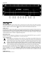 4
4
-
 5
5
-
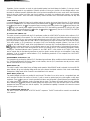 6
6
-
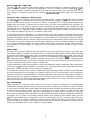 7
7
-
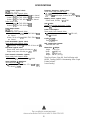 8
8
-
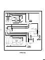 9
9
-
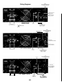 10
10
-
 11
11
-
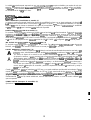 12
12
-
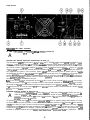 13
13
-
 14
14
-
 15
15
-
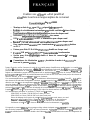 16
16
-
 17
17
-
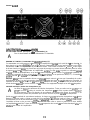 18
18
-
 19
19
-
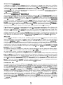 20
20
-
 21
21
-
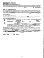 22
22
-
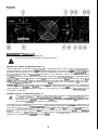 23
23
-
 24
24
-
 25
25
-
 26
26
-
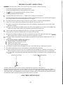 27
27
-
 28
28


Peavey CS 3000G Manual de usuario
- Categoría
- Altavoces de la barra de sonido
- Tipo
- Manual de usuario
- Este manual también es adecuado para
en otros idiomas
- français: Peavey CS 3000G Manuel utilisateur
- English: Peavey CS 3000G User manual
- Deutsch: Peavey CS 3000G Benutzerhandbuch
Artículos relacionados
-
Peavey PV 1200 Professional Stereo Power Amp Manual de usuario
-
-
-
-
-
 Peavy PV Series Power Amplifer El manual del propietario
-
-
-
-

