Poulan 1950 El manual del propietario
- Categoría
- Motosierras inalámbricas
- Tipo
- El manual del propietario

Poulan
®
i_ Please do not return unit to retailer.
Por favor, no devuelva el aparato al lugar de compra.
Veuillez ne pas retourner I'outil au d_taillant.
• 1-800-554-6723
www.poulan.com
Instruction Manual
Manual de Instrucciones
Manuel d'lnstructions
1950 / 1975 / 2050 / 2055 / 2075 / 2150
2155 / 2175 / 2350 / 2375 / 2150PR
A
For Occasional Use Only c(UL)us
v
WARNING:
Read and follow all Safety Rules and Operating Instructions before
using this product. Failure to do so can result in serious injury.
ADVERTENCIA:
Lea el manual de instrucciones y siga todas las advertencias e en-
strucciones de seguridad. El no hacerlo puede resultar en lesiones
graves.
AVERTISSEMENT:
l_ire le manuel d'instructions et bien respecter tousles avertisse-
ments et toutes les instructions de s_curit6. Tout d_faut de le faire
pourrait entrafner des blessures graves.
Electrolux Home Products, Inc.
250 Bobby Jones Expressway
Augusta, GA 30907
Electrolux Canada Corporation
6150 McLaughlin Road
Mississauga, Ontario L5R 4C2
[] From the EtectroluxGroup. The world's No.l choice,
I_ITCIJF_,CLE,_N/NGAN_)OUTDOOR,_ppIJAN_ESCOM_NEIJ
Copyright (02002 Electrolux Home Products, Inc. 530163675 11/22/02

WARNINGt This chain
saw can be dangerous! Care-
lessor improperuse can cause
sedous or even fatal injury.
Read and understand the
instruction manual before
using the chain saw.
Always wear appropriate ear protection, eye protection and head protection.
Always use two hands when operating the chain saw.
WARNINGt Contacting the guide bar tip with any object
should be avoided; tip contact may cause the guide bar to
move suddenly upward and backward, which may cause se-
rious injury.
Measured maximum kickback value without chain brake for the bar
and chain combination on the label.
_ WARNING: Always disconnect
spark plug wire and place wire where it can-
not contact spark plug to prevent accidental
starting when setting up, transporting, ad-
justing or making repairs except carburetor
adjustments.
Because a chain saw is a high-speed wood-
catting tool, special safety precautions must
be observed to reduce the risk of accidents.
Careless or improper use of this tool can
cause serious injury.
PLAN AHEAD
• Read this manual carefully until you com-
pletely understand and can follow all safety
rules, precautions, and operating instruc-
tions before attempting to use the unit.
• Restrict the use of your saw to adult users
who understand and can follow safety
rules, precautions, and operating instruc-
tions found in this manual.
• Wear protective gear. Always use steel-
toed safety footwear with non-slip soles;
snug-fitting clothing; heavy-duty, non-slip
gloves; eye protection such as non-fog-
ging, vented goggles or face screen; an
approved safety hard hat; and sound bard-
ers (ear plugs or mufflers) to protect your
hearing. Regular users should have hear-
ing checked regularly as chain saw noise
can damage hearing. Secure hair above
shoulder length.
Hearing Safety Hat
Protection _Eye
"_t _ Protection
Snug
Heavy Duty
Clothing Gloves
Safety Safety Chaps
Shoes
• Keep all parts of your body away from the
chain when the engine is running.
• Keep children, bystanders, and animals a
minimum of 30 feet (1g meters) away from
the work area. Do not allow other people
or animals to be near the chain saw when
starting or operating the chain saw.
• Do not handle or operate a chain saw when
you are fatigued, ill, or upset, or if you have
taken alcohol, drugs, or medication. You
must be in good physical condition and men-
tally alert. Chain saw work is strenuous. If
you have any condition that might be aggra-
vated by strenuous work, check with your
doctor before operating a chain saw.

• Carefullyplanyoursawingoperationinad-
vance.Donotstartcuttinguntilyouhavea
clearworkarea,securefooting,and,ifyou
arefellingtrees,aplannedretreatpath.
OPERATE YOUR SAW SAFELY
• Do not operate a chain saw with one hand.
Serious injury to the operator, helpers, by-
standers or any combination of these per-
sons may result from one-handed opera-
tion. A chain saw is intended for
two-handed use.
• Operate the chain saw only in a well-venti-
lated outdoor area.
• Do not operate saw from a ladder or in a
tree.
• Make sure the chain will not make contact
with any object while starting the engine.
Never try to start the saw when the guide
bar is in a cut.
• Do not put pressure on the saw at the end
of the cut. Applying pressure can cause
you to lose control when the cut is com-
pleted.
• Stop the engine before setting the saw
down.
• Do not operate a chain saw that is dam-
aged, improperly adjusted, or not com-
pletely and securely assembled. Always
replace bar, chain, hand guard, or chain
brake immediately if it becomes damaged,
broken or is otherwise removed.
• With the engine stopped, hand carry the
chain saw with the muffler away from your
body, and the guide bar and chain to the
rear, preferably covered with a scabbard.
MAINTAIN YOUR SAW IN GOOD
WORKING ORDER
• Have all chain saw service performed by a
qualified service dealer with the exception
of the items listed in the maintenance sec-
tion of this manual. Forexample, if improp-
er tools are used to remove or hold the fly-
wheel when servicing the clutch, structural
damage to the flywheel can occur and
cause the flywheel to burst.
• Make certain the saw chain stops moving
when the throttle trigger is released. For
correction, refer to CARBURETOR AD-
JUSTMENTS.
• Never modify your saw in any way.
• Keep the handles dry, clean, and free ofoil
or fuel mixture.
• Keep fuel and oil caps, screws, and fas-
teners securely tightened.
• Use only Poulan® accessories and re-
placement parts as recommended.
HANDLE FUEL WITH CAUTION
• Do not smoke while handling fuel or while
operating the saw.
• Eliminate all sources of sparks or flame in
the areas where fuel is mixed or poured.
There should be no smoking, open flames,
or workthat could cause sparks. Allow en-
gine to cool before refueling.
• Mix and pour fuel in an outdoor area on
bare ground; store fuel in a cool, dry, well
ventilated place; and use an approved,
marked container for all fuel purposes.
Wipe up all fuel spills before starting saw.
• Move at least 10 feet (3 meters) from fuel-
ing site before starting engine.
• Turn the engine off and let saw cool in a
non-combustible area, not on dry leaves,
straw, paper, etc. Slowly remove fuel cap
and refuel unit.
• Store the unit and fuel in an area where fuel
vapors cannot reach sparks or open
flames from water heaters, electric motors
or switches, furnaces, etc.
KICKBACK
_,WARNING: Avoid kickback which
can result in serious injury. Kickback is the
backward, upward or sudden forward motion
of the guide bar occurring when the saw
chain near the upper tip of the guide bar con-
tacts any object such as a log or branch, or
when the wood closes in and pinches the
saw chain inthe cut. Contacting a foreign ob-
ject in the wood can also result in loss of
chain saw control.
• Rotational Kickback can occur when the
moving chain contacts an object at the up-
per tip of the guide bar. This contact can
cause the chain to dig into the object,
which stops the chain for an instant. The
result is a lightning fast, reverse reaction
which kicks the guide bar up and back to-
ward the operator.
• Pinch-Kickback can occur when the the
wood closes in and pinches the moving
saw chain in the cut along the top of the
guide bar and the saw chain is suddenly
stopped. This sudden stopping of the
chain results in a reversal of the chain
force used to cut wood and causes the
saw to move in the opposite direction of the
chain rotation. The saw is driven straight
back toward the operator.
• Pull-In can occur when the moving chain
contacts a foreign object in the wood in the
cut along the bottom of the guide bar and the
saw chain is suddenly stopped. This sudden
stopping pulls the saw forward and away
from the operator and could easily cause the
operator to lose control of the saw.
Avoid Pinch-Kickback:
• Be extremely aware of situations or ob-
structions that can cause material to pinch
the top of or otherwise stop the chain.
• Do not cut more than one log at a time.
• Do not twist the saw as the bar is with-
drawn from an undercut when bucking.
Avoid Pull-In:
• Always begin cutting with the engine at full
speed and the saw housing against wood.
• Use wedges made of plastic or wood.
Never use metal to hold the cut open.
_i //'_-_- Kickback Path

_ AvoidObstructions
ClearTheWorkingArea
REDUCE THE CHANCE OF
KICKBACK
• Recognize that kickback can happen.
With a basic understanding of kickback,
you can reduce the element of surprise
which contributes to accidents.
• Never let the moving chain contact any ob-
ject at the tip of the guide bar.
• Keep the working area free from obstruc-
tions such as other trees, branches, rocks,
fences, stumps, etc. Eliminate or avoid
any obstruction that your saw chain could
hit while you are cutting. When cutting a
branch, do not let the guide bar contact
branch or other objects around it.
• Keep your saw chain sharp and properly
tensioned. A loose or dull chain can in-
crease the chance of kickback occurring.
Follow manufacturer's chain sharpening
and maintenance instructions. Check ten-
sion at regular intervals with the engine
stopped, never with the engine running.
Make sure the chain brake nuts are se-
curely tightened after tensioning the chain.
• Begin end continue cutting at full speed. If
the chain is moving at a slower speed,
there is greater chance of kickback occur-
ring.
• Cut one log at a time.
• Use extreme caution when re-entering a
previous cut.
• DO not attempt cuts starting with the tip of
the bar (plunge cuts).
• Watch for shifting logs or other forces that
could close a cut and pinch or fall into
chain.
• Use the Reduced-Kickback Guide Bar
and Low-Kickback Chain specified for
your saw.
MAINTAIN CONTROL
Stand to the
hand positions
Elbow locked
Thumb on underside of
handlebar
• Keep a good, firm grip on the saw with both
hands when the engine is running and
don't let go. A firm grip will help you reduce
kickback and maintain control of the saw.
Keep the fingers of your left hand encir-
cling and your left thumb under the front
handlebar. Keep your right hand com-
pletely around the rear handle whether
your are right handed or left handed. Keep
your left arm straight with the elbow
looked.
• Position your left hand on the front handle-
bar so it is in a straight line with your right
hand on the rear handle when making
bucking cuts. Never reverse right and left
hand positions for any type of cutting.
• Stand with yoor weight evenly balanced on
both feet.
• Stand slightly to the left side of the saw to
keep your body from being in a direct line
with the cutting chain.
• Do not overreach. You could be drawn or
thrown off balance and lose control of the
saw.
• DO not cut above shoulder height. Itis diffi-
cult to maintain control of saw above
shoulder height.
KICKBACK SAFETY FEATURES
_WARNING: The following features
are included on your saw to help reduce the
hazard of kickback; however, such features
will not totally eliminate this danger. As a
chain saw user, do not rely only on safety de-
vices. You must follow all safety precau-
tions, instructions, and maintenance in this
manual to help avoid kickback and other
forces which can result in serious injury.
• Reduced-Kickback Guide Bar, designed
with a small radius tip which reduces the
size of the kickback danger zone on the
bar tip. A Reduced-Kickback Guide Bar
has been demonstrated to significantly re-
duce the number and seriousness of kick-
backs when tested in accordance with
safety requirements for gasoline powered
chain saws as set by ANSI B175.1.

Reduced Kickback Symmetrical Guide Bar
aJl Radius Tip
Symmetdce3 Guide Bar _.
[
Large Radius Tip
• Low-Kickback Chain, designed with a
contoured depth gauge and guard link
which deflect kickback force and allow
wood to gradually ride into the cutter. Low-
Kickback Chain has met kickback per-
formance requirements when tested on a
representative sample of chain saws be-
low 3.8 cubic inch displacement specified
in ANSI B175.1.
Contoured Depth GaL_ge
_£k Elongated Guard LinkDeflects
ickback force
Low- KJckback
and allows
wood
Chain to gradually ride
into cutter
_L_Can Obstruct MateriaJ
Not a Low- KJckback Chain
• Front Hand Guard, designed to reduce the
chance of your left hand contacting the chain
if your hand slips off the front handlebar.
• Position of front and rear handlebars, de-
signed with distance between handles and
"in-line" with each other. The spread and
"in-line" position of the hands provided by
this design work together to give balance
and resistance in controlling the pivot of
the saw back toward the operator if kick-
back occurs.
CHAIN BRAKE AND CKA ANGLE
• Chain Brake, designed to stop the chain in
the event of kickback.
_,WARNING: WE DO NOT REP-
RESENT AND YOU SHOULD NOT AS-
SUME THAT THE CHAIN BRAKE WILL
PROTECT YOU iN THE EVENT OF A
KICKBACK. Kickback is a lightning fast ac-
tion which throws the bar and rotating chain
back and up toward the operator. Kickback
can be caused by allowing contact of the bar
tip in the danger zone with any hard object.
Kickback can also be caused by pinching the
saw chain along the top of the guide bar. This
action may push the guide bar rapidly back
toward the operator. Either of these events
may cause you to lose control of the saw
which could result in serious injury or even
death. DO NOT RELY UPON ANY OF THE
DEVICES BUILT INTO YOUR SAW. YOU
SHOULD USE THE SAW PROPERLY AND
CAREFULLY TO AVOID KICKBACK. Re-
duced-kickback guide bars and low-kick-
back saw chains reduce the chance and
magnitude of kickback and are recom-
mended. Your saw has a low kickback chain
and bar as original equipment. Repairs on a
chain brake should be made by an autho-
rized servicing dealer. Take your unit to the
place of purchase if purchased from a ser-
vicing dealer, or to the nearest authorized
master service dealer.
• Tip contact in some cases may cause a light-
ning fast reverse REACTION, kicking guide
bar up and back toward operator.
• Pinching the saw chain along the top of the
guide bar may push the guide bar rapidly
back toward the operator.
• Either of these reactions may cause you to
lose control of the saw which could result in
sedous injury. Do not rely exclusively upon
devices built into your saw.
_,WARNING: CompLied kickback
angle (CKA) listed on your saw and listed in the
CKA table below represents angle of kickback
your bar and chain combinations will have
when tested in accordance with CSA (Cana-
dian Standards Association) and ANSI stan-
dards. When purchasing replacement bar and
chain, considerations should be given to the
lower CKA values. Lower CKA values repre-
sent safer angles to the user, higher values in-
dicate more angle and higher kick energies.
Computed angles represented indicate total
energy and angle associated without activation
of the chain brake during kickback. Activated
angle represents chain stopping time relative to
activation angle of chain break and resulting
kick angle of saw. In all cases lower CKA val-
ues represent a safer operating environment
for the user.
The following guide bar and chain combina-
tions meet kickback requirements of CSA
Standards Z62.1, Z62.3, & ANSI B175.1 when
used on saws listed in this manual. Use of bar
and chain combinations other than those listed
is not recommended and may not meet the
CKA requirements per standard.
Computed kickback angle (CKA) Table
BAR
MODEL P/N
1950/1975/2080 952044368
2055/2078/
2150/2150PR
2155/2178/
2350/2375
Length CHAIN P/N
14" 952051209
952044370 16" 952051211
952044418 18" 952051338
CKA without chain brake
24 °
19°
14°

NOTE:Ifthissawistobeusedforcom-
merciallogging,achainbrakeisrequired
andshallnotberemovedorotherwisedis-
abledtocomplywithFederalOSHARegula-
tionsforCommercialLogging.
SAFETYNOTICE:Exposuretovibrations
throughprolongeduseofgasolinepowered
handtoolscouldcausebloodvesselornerve
damageinthefingers,hands,andjointsof
peopleproneto circulationdisordersor
abnormalswellings.Prolongeduseincold
weatherhasbeenlinkedtobloodvessel
damagein otherwisehealthypeople.If
symptomsoccursuchasnumbness,pain,
lossofstrength,changeinskincolorortexture,
orlossoffeelinginthefingers,hands,orjoints,
discontinuetheuseofthistoolandseek
medicalattention.Ananti-vibrationsystem
doesnotguaranteetheavoidanceofthese
problems.Userswhooperatepowertoolson
acontinualandregularbasismustmonitor
closelytheirphysicalconditionandthe
conditionofthistool.
SPECIALNOTICE:Yoursawisequipped
withatemperaturelimitingmufflerandspark
arrestingscreenwhichmeetsthe
requirementsofCaliforniaCedes4442and
4443.AllU.S.forestlandandthestatesof
California,Idaho,Maine,Minnesota,New
Jersey,Oregon,andWashingtonrequireby
lawthatmanyinternalcombustionengines
tobeequippedwithasparkarrestingscreen.
Ifyouoperateachainsawinastateorlocale
wheresuchregulationsexist,youarelegally
responsibleformaintainingtheoperating
conditionoftheseparts.Failuretodosois
aviolationofthelaw.RefertotheSERVICE
sectionfor maintenanceof thespark
arrestingscreen.
FailuretofollowallSafetyRulesandPrecau-
tionscanresultinseriousinjury.Ifsituations
occurwhicharenotcoveredinthismanual,
usecareandgoodjudgement.Ifyouneed
assistance,contactyourauthorizedservice
dealerorcall1-800-554-6723.
STANDARDS:ThissawislistedbyUnder-
writer'sLaboratedes,Inc.,inaccordancewith:
ANSI B175.1-2000 American National
Standards for Gasoline-Powered Chain
Saws - Safety Requirements
CSA Z62.1-1995 Chain Saws - Occupa-
tional Health and Safety
CSA Z62.3-1996 Chain Saw Kickback Oc-
cupational Health and Safety
Protective gloves (not provided) should be
worn during assembly.
ATTACHING THE BAR & CHAIN (If not
already attached)
41_WARNING: If receivedassembled,
repeat all steps to ensure your saw isproperly
assembled and all fasteners are secure. Al-
ways wear gloves when handling the chain.
The chain is sharp and can cut you even when
it is not moving!
1. Loosen and remove the chain brake nuts
and the chain brake from the saw.
2. Remove the plastic shipping spacer (if
present).
Location of shipping spacer
O
ChainBak
Ch Nuts
Bar Tool
3. An adjusting pin and screw is used to ad-
just the tension of the chain. It is very im-
portant when assembling the bar, that the
pin located on the adjusting screw aligns
into a hole in the bar. Turning the screw will
move the adjustment pin up and down the
screw. Locate this adjustment before you
begin mounting the bar onto the saw. See
illustration below.
Inside view of
hain Brake
Adjustment located on Chain Brake
4. Turn the adjusting screw by hand coun-
terelockwise until the adjusting pin just
touches the step. This should allow the
pin to be near the correct position.
5. Slide guide bar behind clutch drum until
guide bar stops against clutch drum
sprocket.
6. Carefully remove the chain from the pack-
age. Hold chain with the drive links as
shown.
rof
DIIRECTION OF ROTATION

Cutters DepthGauge
DriveLinks
Place chain onto the sprocket
7. Place chain over and behind dutch, fitting
the drive links in the dutch drum sprocket.
8. Fit bottom of drive links between the
teeth in the sprocket in the nose of the
guide bar.
9. Fit chain drive links into bar groove.
10. Pull guide bar forward until chain is snug
in guide bar groove. Ensure all drive
links are in the bar groove.
NOTE: CHAIN BRAKE MUST BE
DISENGAGED BEFORE INSTALLA-
TION ON THE SAW. TO DISENGAGE
CHAIN BRAKE, PULL THE FRONT
HAND GUARD BACK TOWARD THE
REAR OF THE CHAIN BRAKE AS
FARAS POSSIBLE (SEE ILLUSTRA-
TION).
DISENGAGED
Front Hand Guard _
ED
/ _"_ Chain Brake
11, Now, install chain brake making surethe
adjusting pin is positioned in the lower
hole in the guide bar. Remember this pin
moves the bar forward and backward as
the screw is turned.
12. Install chain brake nuts and finger tighten
only. Once the chain is tensioned, you
will need to tighten chain brake nuts.
CHAIN TENSION
(including units with chain already installed)
NOTE: When adjusting chain tension,
make sure the chain brake nuts are finger
tight only. Attempting to tension the chain
when the chain brake nuts are tight can
cause damage.
Checking the tension:
Use the screwdriver end of the chain adjust-
ment tool (bar tool) to move the chain around
the bar. If the chain does not rotate, it is too
tight. Iftoo loose, the chain will sag below the
bar.
Chain Brake Nuts Tool (Bar Tool)
Adjusting the tension:
Chain tension is very important. Chain
stretches during use. This is especially true
during the first few times you use your saw.
Always check chain tension each time you
use and refuel your saw.
You can adjust the chain tension by loosen-
ing the chain brake nuts and turning the ad-
justing screw 1/4 of a turn while lifting up on
the bar.
• Ifchain istootight, turn adjusting screw 1/4
turn counterclockwise.
• If chain is too loose, turn adjusting screw
1/4 turn clockwise.
,_o_Adjusting // ./
Screw _ //
Chain Brake Nuts Guide Bar
Adjusting Screw - 1/4 Turn
• Lift up the tip of the bar and securely tight-
en the chain brake nuts with the bar tool.
• Recheck chain tension.
Chain Brake
=,'k
dlIWARNING: If the saw is operated
with a loose chain, the chain could jump off
the guide bar and result in serious injury.

KNOW YOUR CHAIN SAW
READ THIS INSTRUCTION MANUAL AND SAFETY RULES BEFORE OPERATING YOUR
CHAIN SAW, Compare the illustrations with your unit to familiarize yourself with the location of
the various controls and adjustments. Save this manual for future reference.
Chain Front Hand Guarcl''_" Front Handle
Adjustment Tool
(Bar Tool) Starter Rope
i1_=====_ ON/STOP
Switch
Chain Muffler
Primer
Bulb
Bar Oil Fill Cap Housing Fuel Mix Fill Cap
e F_cS_Idle/_f_/CylinderCover !
Fast Idle !
Throttle Lock Chain
LT°h_°kt°tlleu_ / f--z"-_ z_"_o , , D rect on
Lockout
AdJusting ___ _,.of Travel
o
.._.,/._.._ ._ _=_ Guide Bar
Throttle Choke
Trigger Knob Chain Chain Nuts Sprocket
Brake Catcher Hole
ON/STOP SWITCH
The ON/STOP SWITCH is used to stop the
engine,
THROTTLE TRIGGER
The THROTTLE TRIGGER controls engine
speed,
THROTTLE LOCK-OUT
The THROTTLE LOCK-OUT must be
pressed before you can squeeze the throttle
tdgger, This feature prevents you from acci-
dentally squeezing the tdgger,
FAST IDLE LOCK
The FAST IDLE LOCK holds the throttle trigger
in the starting position, Activate the fast idle
lock by pressing the throttle lockout and
squeezing the throttle trigger. With the throttle
tdgger squeezed, press the fast idle lock. Re-
lease the throttle lockout and tdgger while hold-
ing the fast idle lock button.
CHOKE KNOB
The CHOKE KNOB activates the choke to
provide additional fuel to the engine dudng cold
starting.
PRIMER BULB
The PRIMER BULB circulates fuel to the oar-
buretor to provide quicker starting.
CHAIN BRAKE
The CHAIN BRAKE is a device designed to
stop the chain if kickback occurs. The chain
brake activates automatically in the event of
kickback. The chain brake activates manually
if the front hand guard is pushed forward. The
chain brake is disengaged by pulling the front
hand guard back toward the front handle as far
as possible.
CHAIN TENSION
It isnormalfor a new chain tostretch during first
15 minL_es of operation. YOU should check
your chain tension frequently. See CHAIN
TENSION under the ASSEMBLY section.
_WARNING: Muffler is very hot dur-
ing and after use. Do not touch the muffler or
allow combustible material such as dry
grass or fuel to do so.

A
dll WARNING: Remove fuel cap slowly
when refueling.
FUELING ENGINE
This engine is certified to operate on un-
tended gasoline. Before operation, gasoline
must be mixed with a good quality synthetic
2-cycte air-cooled engine oil designed to be
mixed at a ratio of 40:1. Poulan/Weed Eater
brand synthetic oil is recommended. Mix
gasoline and oil at a ratio of 40:1. A40:1 ratio
is obtained by mixing 3.2 ounces (95 ml) ofoit
with 1 gallon (4 liters) of untended gasoline.
Included with this saw isa 3.2 ounce contain-
er of oil Pour the entire contents of this con-
tainer into 1gatlon of gasoline to achieve the
proper fuel mixture.
DO NOT USE automotive oil or boat oil. These
oils will cause engine damage. When mixing
fuel, foltow instructions printed on container.
Once oil is added to gasoline, shake container
momentarily to assure that the fuel isthorough-
ty mixed. Always read and follow the safety
rules relating to fuel before fueling your unit.
BAR AND CHAIN LUBRICATION
The bar and chain require continuous lubri-
cation. Lubrication is provided by the auto-
matic oiler system when the oil tank is kept
filled. Lack ofoil will quickly ruin the bar and
chain. Too little oil will cause overheating
shown by smoke coming from the chain and/
or discoloration of the bar.
In freezing weather oil will thicken, making it
necessary to thin bar and chain oil with a
small amount (5 to 10%) of #1 Diesel Fuel or
kerosene. Bar and chain oil must be free
flowing for the oil system to pump enough oil
for adequate lubrication.
Genuine Poulan ® bar and chain oil is recom-
mended to protect your unit against exces-
sive wear from heat and friction. Poulan®
oil resists high temperature thinning. If Pou-
lan® bar aod chein oil is not available, usea
good grade SAE 30 oil.
• Never use waste oil for bar and chain lubd-
cation.
• Always stop the engine before removing
the oil cap.
IMPORTANT
Experience indicates that alcohol-blended
fuels (called gasoho[ or using ethanol or
methanol) can attract moisture which leads
to separation and formation of acids during
storage. Acidic gas can damage the fuel
system of an engine while in storage. To
avoid engine problems, the fuel system
should be emptied before storage for 30
days or longer. Drain the gas tank, start the
engine and let it run until the fuel lines and
carburetor are empty. Use fresh fuel next
season. See STORAGE section for addi-
tional information.
_WARNING:
The chain must not
move when the engine runs at idle speed. If
the chain moves at idle speed refer to CAR-
BURETOR ADJUSTMENT within this
manual. Avoid contact with the muffler. Ahot
muffler can cause serious burns.
To stop the engine move the ON/STOP
switch to the STOP position.
To start the engine hold the saw firmly on
the ground as illustrated. Make sure the
chain is free to turn without contacting any
object.
Use only 15"-18" of rope per pull,
Hold sew firmly while pulling starter rope
Starter rope handle
Left hand
on front
handle
rear handle
IMPORTANT POINTS TO REMEMBER
When pullin9 the starter rope, do not use the
full extent of the rope as this can cause the
rope to break. Do not let starter rope snap
back, Hold the handle and let the rope re-
wind slowly.
NOTE: Do not attempt to cut material with
the fast idle lock button in the locked position.
STARTING A COLD ENGINE (or
warm engine after running out of
fuel)
ON/STOP SWITCH
(SIDE VIEW)
ON
STOP
1. Move ON/STOP switch to the ON posi-
tion.
2. Pull choke knob out to the full extent.
3. Slowly press primer bulb 6 times.
4. Squeeze and hold throttle trigger. With
thumb press fast idle lock down; then re-
lease throttle trigger.
Fast idle lock button_..._
Throttle _
Iock-ou
Throttle__Choke knob
trigger
5. Sharply pull the starter rope handle 5
times with your right hand. Then, pro-
ceed to the next step.

NOTE:Iftheengine sounds as if it is try-
ing to start before the 5th pull, stop pulling
and immediately proceed to the next step.
6. Push the choke knob in completely (to
the OFF position); pull the starter rope
until the engine starts.
CHOKE
:IEW)
k
Choke knob OFF FULL
7. Allow the engine to run for approximately
5 seconds. Then, squeeze and release
throttle tdgger to allow engine to return to
idle speed.
STARTING A WARM ENGINE:
1. Move ON/STOP switch to the ON posi-
tion.
2. Push the choke knob in completely (to
the OFF position).
3. Slowly press primer bulb 6 times.
4. Squeeze and hold throttle trigger. With
thumb press fast idle lock down; then re-
lease throttle trigger.
5. Sharply pull the starter rope with your
right hand until the engine starts.
6. Squeeze and release throttle trigger to
allow engine to return to idle speed.
DIFFICULT STARTING (or starting a
flooded engine):
The engine may be flooded with too much
fuel if it has not started after 10 pulls.
Flooded engines can be cleared of excess
fuel by following the warm engine starting
procedure listed above. Insure the ON/
STOP switch is in the ON position.
Starting could require pulling the starter rope
handle many times depending on how badly
the unit isflooded. If engine fails to start, refer
to the TROUBLESHOOTING TABLE or call
1-800-554-6723.
CHAIN BRAKE
_WARNING: if the brake band is
worn too thin it may break when the chain
brake istriggered. With a broken brake band,
the chain brake will not stop the chain. The
chain brake should be replaced by an autho-
rized service dealer if any part is worn to less
than 0.020" (0.5 mm) thick. Repairs on a
chain brake should be made by an autho-
rized service dealer. Take your unit to the
place of purchase if purchased from a ser-
vicing dealer, or to the nearest authorized
master service dealer.
• This saw is equipped with a chain brake.
The brake is designed to stop the chain if
kickback occurs.
• The inertia-activated chain brake is
activated if the front hand guard is pushed
forward, either manually (by hand) or
automatically (by sudden movement).
• If the brake is already activated, it is
disengaged by pulling the front hand guard
back toward the front handle as far as
possible.
• When cutting with the saw, the chain brake
must be disengaged.
Disengaged
_ii_Engag ed
Braking function control
CAUTION: The chain brake must be
checked several times daily. The engine
must be running when performing this proce-
dure. This isthe only instance when the saw
should be placed on the ground with the en-
gine running.
Place the saw on firm ground. Grip the rear
handle with your right hand and the front han-
dle with your left hand. Apply full throttle by
fully depressing the throttle trigger. Activate
the chain brake by turning your left wrist
against the hand guard without releasing
your grip around the front handle. The chain
should stop immediately.
Inertia activating function control
_B_WARNING: Whenperformingthe
following procedure, the engine must be
turned off.
Grip the rear handle with your right hand and
the front handle with your left hand. Hold the
chain saw approximately 14" (35 cm) above
a stump or other wooden surface. Release
your grip on the front handle and use the
weight of the saw to let the top of the guide
bar fall forward and contact the stump.
When the tip of the bar hits the stump, the
brake should activate.
10
IMPORTANT POINTS
• Check chain tension before first use and
after 1 minute of operation. See CHAIN
TENSION in the ASSEMBLY section.
• Cut wood only. Do not cut metal, plastics,
masonry, non-wood building materials, etc.
• Stop the saw if the chain strikes a foreign
object. Inspect the saw and repair or re-
place parts as necessary.
• Keep the chain OL_of dirt and sand. Even a
small amount of dirt will quickly dull a chain
and thus increase the possibility of kickback.
• Practice cutting a few small logs using the
following techniques to get the "feel" of us-
ing your saw before you begin a major
sawing operation.
Squeeze the throttle trigger and allow
the engine to reach full speed before
cutting.
Begin cutting with the saw frame
against the log.
Keep the engine at full speed the en-
tire time you are cutting.

Allowthechaintocutforyou.Exert
onlylightdownwardpressure.Ifyou
forcethecut,damagetothebar,
chain,orenginecanresult.
Releasethethrottletriggerassoonas
thecutiscompleted,allowingtheen-
ginetoidle.Ifyourunthesawatfull
throttlewithoutacuttingload,unnec-
essarywearcanoccurtothechain,
bar,andengine.
Toavoidlosingcontrolwhencutis
complete,donotputpressureonsaw
atendofcut.
• Stoptheenginebeforesettingthesaw
downaftercutting.
TREE FELLING TECHNIQUES
_WARNING: Check for broken or
dead branches which can fall while cutting
causing serious injury. Do not cut near build-
ings or electrical wires if you do not know the
direction of tree fall, nor cut at night since you
will not be ale to see well, nor during bed
weather such as rain, snow, or strong winds,
etc. If the tree makes contact with any utility
line, the utility company should be notified
immediately.
• Carefully planyoursawingoperetion inad-
vance.
• Clear the work area. You need aclear area
all around the tree so you can have secure
footing.
• The chain saw operator should keep on
the uphill side of the terrain as the tree is
likely to roll or slide downhill after it is felled.
• Study the natural conditions that can cause
the tree to fall in a particular direction.
Natural conditions that can cause e tree to
fall in a particular direction include:
• The wind direction and speed.
• The lean of the tree. The lean of a tree
might not be apparent due to uneven or
sloping terrain. Use a plumb or level to de-
termine the direction of tree lean.
• Weight and branches on one side.
• Surrounding trees and obstacles.
Look for decay and rot Ifthetrunk is rotted,
it can snap and fall toward the operator.
Check for broken or dead branches which
can fall on you while cutting.
Make sure there is enough room for the tree to
fall. Maintain a distance of 2-1J2tree lengths
from the nearest person or other objects. En-
gine noise can drown OL_a warning call.
Remove dirt, stones, loose bark, nails, sta-
ples, and wire from the tree where cuts are to
be made.
Plan a clear retreat path to the rear and diag-
onal to the line of fall.
_ Plan a clear retreat path
;_.... O"_'- Direction of Fall
FELLING LARGE TREES
(6 inches in diameter or larger)
The notch method is used to fell large trees.
A notch is cut on the side of the tree in the de-
sired direction of fall. After a felling cut is
made on the opposite side of tree, the tree
will tend to fall into the notch.
NOTE: If the tree has large buttress roots,
remove them before making the notch. If us-
ing saw to remove buttress roots, keep saw
chain from contacting ground to prevent dull-
ing of the chain.
NOTCH CUT AND FELLING THE
TREE
• Make notch cut by cutting the top of the
notch first. Cut through 1/3of the diameter
of the tree. Next complete the notch by cut-
ting the bottom of the notch. See illustra-
tion. Once the notch is cut remove the
notch of wood from the tree.
Final (felling) cut here. 2 in-
ches above center of notch.
I//
Notch " i"
Second cut
• After removing the wood from the notch,
make the felling cut on the opposite side of
the notch. This is done by making e cut
about two inches higher than the center of
the notch. This will leave enough uncut
wood between the felling cut and the notch
to form e hinge. This hinge will help pre-
vent the tree from falling in the wrong direc-
tion.
Hinge holds tree on stump and helps
control fall
Opening
of felling
cut
Closing of
notch
NOTE: Before felling cut is complete, use
wedges to open the cut if necessary to
control the direction of fall. To avoid kickback
end chain damage, use wood or plastic
wedges, but never steel or iron wedges.
• Be alert to signs that the tree is ready to
fall: cracking sounds, widening of the fell-
ing cut, or movement in the upper
branches.
11

• As tree starts to fall, stop saw, put it down,
and get away quickly on your planned re-
treat path.
• DO NOT cut down a partially fallen tree
with your saw. Be extremely cautious with
partially fallen trees that may be poorly
supported. When a tree doesn't fall com-
pletely, set the saw aside and pull down the
tree with a cable winch, block and tackle,
or tractor.
CUTTING A FALLEN TREE
(BUCKING)
Bucking is the term used for cutting a fallen
tree to the desired log size.
_ WARNING: Do not staod on the log
being cut. Any portion can roll causing loss
of footing and control. Do not stand downhill
of the log being cut.
IMPORTANT POINTS
• Cut only one log at a time.
• Cut shattered wood very carefully; sharp
pieces of wood could be flung toward oper-
ator.
• Use a sawhorse to cut small logs. Never
allow another person to hold the log while
cutting and never hold the log with your leg
or foot.
• Do not cut in an area where logs, limbs,
and roots are tangled such as in a blown
down area. Drag the logs into a clear area
before cutting by pulling out exposed and
cleared logs first.
TYPES OF CUTTING USED FOR
BUCKING
_,WARNING: If saw becomes
pinched or hung in a log, don't try to force it
out. You can lose control of the saw resulfing
in injury aod/or damage tothe saw. Stop the
saw, drive awedge of plastic or wood into the
cut until the saw can be removed easily. Re-
start the saw and carefully reenter the cut. To
avoid kickback and chain damage, do not
use a metal wedge. Do not attempt to restart
your saw when it is pinched or hung in a log.
Undercutting involves cutting on the under-
side of the log with top of saw against the log.
When undercutting use light upward pres-
sure. Hold saw firmly and maintain control.
The saw will tend to push back toward you.
i_ WARNING: Neverturn saw upside
down to undercut. The saw cannot be con-
trolled in this position.
Always make your first cut on the compres-
sion side of the log. The compression side of
the log is where the pressure of the log's
weight is concentrated.
First cut on compression side of log
Second cut
Second cut
First cut on compression side of log
BUCKING WITHOUT A SUPPORT
• Overcut through 1/3of the diameter of the
log.
• Roll the log over and finish with a second
overcut.
• Watch for logs with a compression side to
prevent the saw from pinching. See il-
lustrations for cutting logs with a compres-
sion side.
BUCKING USING A LOG OR
SUPPORT STAND
• Remember your first cut is always on the
compression side of the log.
_Refer to the illustrations below for your
rst and second cut)
• Your first cut should extend 1/3 of the
diameter of the log.
• Finish with your second cut.
Use a wedge to remove pinched saw
Turn saw OFF and use a plastic or
wooden wedge to force cut open.
Overcutting begins on the top side of the log
with the bottom of the saw against the log.
When overcutting use light downward pres-
sure,
ve,eutt,°g
12
Using a log for support
2 ndCut'NL
" -:'_ tStCu t
_1 st Cut
L[ _
', d,

Using a support stand
2nd Cut
1st Cut
Ist Cut
/
LIMBING AND PRUNING
_WARNING: Be alert for and guard
against kickback. Ds not allow the moving
chain to contact any other branches or ob-
jects at the nose of the guide bar when limb-
log or pruning. Allowing such contact can re-
sult in serious injury.
illWARNING: Never climb into a tree
to limb or prune. Do not stand on ladders,
platforms, a log, or in any position which can
cause you to lose your balance or control of
the saw.
IMPORTANT POINTS
• Work slowly, keeping both hands firmly
gripped on the saw. Maintain secure foot-
ing and balance.
• Watch OL_for spriogpoles. Springpoles are
small size limbs which can catch the saw
chain and whip toward you or pull you off bal-
ance. Use extreme caution when cutting
small size limbs or slender material
• Be alert for springback. Watch out for
branches that are bent or under pressure.
Avoid being struck by the branch or the
saw when the tension in the wood fibers is
released.
• Keep a clear work area. Frequently clear
branches out of the way to avoid tripping
over them.
LIMBING
• Always limb atree after it iscut down. Only
then can limbing be done safely and prop-
erly.
• Leave the larger limbs underneath the
felled tree to support the tree as you work.
• Start at the base of the felled tree and work
toward the top, cutting branches and
limbs. Remove small limbs with one cut.
• Keep the tree between you and the chain.
Cut from the side of the tree opposite the
branch you are cutting.
• Remove larger, supporting branches with
the cutting techniques described in BUCK-
ING WITHOUT A SUPPORT.
• Always use an overcut to cut small and
freely hanging limbs. Undercutting could
cause limbs to fall and pinch the saw.
PRUNING
i_WARNING: Limit pruning to limbs
shoulder height or below. Do not cut if
branches are higher than your shoulder. Get
a professional to do the job.
Make your first cut 1/3 of the way
through the bottom of the limb.
Next make a 2nd cut all the way
through the limb. Then cut a third
overeut leaving a 1 to 2 inch collar
from the truck of the tree.
_Th_Jdic Second cut'_°!t
Collar tit_/
_ljV ..I,..... First cut
f Pruning technique
lliWARNING: Disconnect the spark
plug before performing maintenance except
for carburetor adjustments.
We recommend aUservice and adjustments
not listed in this manual be performed by an
authorized or Master Service Dealer.
MAINTENANCE SCHEDULE
Check:
Fuel mixture level ....
Bar lubrication .....
Chain tension .....
Chain sharpness ,.
For damaged parts
For loose caps ....
For loose fasteners.
For loose parts ....
Inspect and Clean:
Bar ................
Complete saw .....
Air filter .............
Before each use
Before each use
Before each use
Before each use
Before each use
Before each use
Before each use
Before each use
Before each use
After each use
Every 5 hours*
Chain brake ........ Every 5 hours*
Spark arresting screen
and muffler ......... Every 25 hours*
Replace spark plug , Yearly
Replace fuel filter,.. Yearly
* Hours of Operation
AIR FILTER
CAUTION: Ds not clean filter in gasoline
or other flammable solvent to avoid creating
a fire hazard or producing harmful evapora-
tive emissions.
Cleaning the air filter:
A dirty air filter decreases engine perform-
ance and increases fuel consumption and
harmful emissions. Always clean after 15
tanks of fuel or 5 hours of operation, which-
ever comes first. Clean more frequently in
13

dusty conditions. A used aire filter can never
be completely cleaned. It is advisable to re-
place your air filter with a new one after every
50 hours of operation, or annually, whichever
comes first.
1. Loosen 3 screws on cylinder cover.
2. Remove cylinder cover.
3. Remove air filter.
4. Cleantheairfilterusinghotsoapywater.
Rinse with clean cool water. Air dry com-
pletely before reinstalling.
5. Lightly oil air filter before installing to im-
prove the efficiency of air filter. Use
2-cycle engine oil or motor oil (SAE 30).
Squeeze excess oil from filter.
6. Reinstall air filter.
7. Reinstall cylinder cover and 3 screws.
Tighten securely.
lieder Cover
Air Filter Screws
Cylinder
Cover
INSPECT MUFFLER AND SPARK
ARRESTING SCREEN
As the unit isused, carbon deposits build up
on the muffler and spark arresting screen,
and must be removed to avoid creating a fire
hazard or affecting engine performance.
Replace the spark arresting screen if breaks
occur.
Muffler Diffuser
/ Spark
• -_/_'l_rvz_ " _,, I Arresting
z /.. I!_%,/_ ,/Screen
Muffler
__ Cover
_-.._'_',_.,"_IN_, _ Screws
Bod_ Cover
CLEANING THE SPARK ARREST-
ING SCREEN
Cleaning is required every 25 hours of op-
eration or annually, whichever comes first.
1. Loosen and remove the 2 muffler cover
screws.
2. Remove the muffler cover (cover snaps
off muffler body).
3. Remove muffler diffuser and spark ar-
resting screen assembly. Notice the
orientation of these parts for reassem-
bling.
4. Clean the spark arresting screen with a
wire brush. Replace screen if breaks are
found.
5. Replace any broken or cracked muffler
parts.
6. Reinstall diffuser and spark arresting
screen assembly with round holes facing
up.
7. Reinstall muffler cover and 2 screws.
Tighten securely.
CARBURETOR ADJUSTMENT
_WARNING: The chain will be mov-
ing during most of this procedure. Wear your
protective equipment and observe all safety
precautions. The chain must not move at idle
speed.
The carburetor has been carefully set at the
factory. Adjustments may be necessary if
you notice any of the following conditions:
• Chain moves at idle. See IDLE SPEED-T
adjusting procedure.
• Saw will not idle. See IDLE SPEED-T ad-
justing procedure.
Idle Speed-T
Allow engine to idle. If the chain moves, idle
is too fast. If the engine stalls, idle istoo slow.
Adjust speed until engine runs without chain
movement (idle too fast) or stalling (idle too
slow). The idle speed screw islocated in the
area above the primer bulb and is labeled T.
• Turn idle speed screw (T) clockwise to in-
crease engine speed.
• Turn idle speed screw (T) counterclock-
wise to decrease engine speed.
If you require further assistance or are unsure
aboL_ performing this procedure, contact your
aL_horized service dealer or call
1-800-554-6723.
BAR MAINTENANCE
if your saw cuts to one side, has to be forced
through the cut, or been run with an improper
amount of bar lubrication it may be neces-
sary to service you r bar. A worn bar will dam-
age your chain and make cutting difficult.
After each use, ensure ON/STOP switch is
in the STOP position, then clean all sawdust
from the guide bar and sprocket hole.
To maintain guide bar:
• Move ON/STOP switch to the STOP posi-
tion.
• Loosen and remove chain brake nuts and
chain brake. Remove bar and chain from
saw.
• Clean the oil holes and bar groove after
each 5 hours of operation.
Remove Sawdust From _J(_
Guide Bar Groo_.__
Oil Holes • Q
• Burring of guide bar rails is a normal
process of rail wear. Remove these burrs
with a flat file.
• When rail top is uneven, use a fiat file to re-
store square edges and sides.
14

'_'_'--File Rail Edge_ N N
and Sides I U I
Square I I
Worn Groove Correct Groove
Replace guide bar when the groove is worn,
the guide bar is bent or cracked, or when
excess heating or burring of the rails occurs.
If replacement is necessary, use only the
guide bar specified for your saw in the repair
parts list or on the decal located on the chain
saw,
CHAIN SHARPENING
Chain sharpening is a complicated task that
requires special tools. We recommended
you refer chain sharpening to a professional
chain sharpener.
IGNITION TIMING
Ignition timing is fixed and nonadjustable.
SPARK PLUG
The spark plug should be replaced each
year to ensure the engine starts easier and
runs better.
1. Loosen 3 screws on cylinder cover.
2. Remove the cylinder cover.
3. Pull off the spark plug boot.
4. Remove spark plug from cylinder and
discard.
5. Replace with Champioo RCJ-7Y spark
plug and tighten securely with a 3/4 inch
socket wrench. Spark plug gap should
be 0.025 inches.
6. Reinstall the spark plug boot.
7. Reinstall the cylinder cover and 3
screws. Tighten securely.
Screws......_ / %CcYonderer
S%k
STORAGE
_,WARNING: Stop engine and allow
to cool, and secure the unit before storing or
transporting in a vehicle. Store unit and fuel
in an area where fuel vapors cannot reach
sparks or open flames from water heaters,
electric motors or switches, furnaces, etc.
Store unit with all guards in place. Position so
that any sharp object cannot accidentally
cause injury to passersby. Store the unit out
of reach of children.
• Before storing, drain all fuel from the unit.
Start engine and allow to run until it stops.
• Clean the unit before storing. Pay particu-
lar attention to the air intake area, keeping
it free of debris. Use a mild detergent and
sponge to clean the plastic surfaces.
• Do not store the unit or fuel in aclosed area
where fuel vapors can reach sparks or an
open flame from hot water heaters, electric
motors or switches, furnaces, etc.
• Store in a dry area out of the reach of chil-
dren.
CAUTION: It is important to prevent gum
deposits from forming in essential fuel system
parts such as the carburetor, fuel filter, fuel
hose, or fuel tank during storage. Alcohol
blended fuels (called gasohol or using ethanol
or methanol) can attract moisture which leads
to fuel mixture separation and formation of
acids during storage. Acidic gas can damage
the engine.
15

TROUBLESHOOTING TABLE
_, WARNING: Always stop unit and disconnect spark plug before performing all of
the recommended remedies below except remedies that require operation of the unit.
TROUBLE CAUSE REMEDY
Engine will not 1. Ignition switch off. 1. Move ignition switch to ON.
start or will run 2. Engine flooded. 2. See "Difficult Starting" in
only a few Operation Section.
seconds after 3. Fuel tank empty. 3. Fill tank with correct fuel mixture.
starting. 4. Spark plug not firing. 4. InstaU new spark plug.
5. Fuel not reaching 5. Check for dirty fuel filter; replace.
carburetor. Check for kinked or spilt fuel line;
repair or replace.
Engine will 1. Idle speed requires 1. See "Carburetor Adjustment" in the
not idle adjustment. Service and Adjustments Section.
properly. 2. Carburetor requires 2. Contact an authorized service dealer.
adjustment.
Engine will not 1. Air filter dirty. 1. Clean or replace air filter.
accelerate, 2. Spark plug fouled. 2. Clean or replace plug and regap.
lacks power, 3. Chain brake engaged. 3. Disengage chain brake.
or dies under 4. Carburetor requires 4. Contact an authorized service dealer.
a load. adjustment.
Engine 1. Too much oil mixed with 1. Empty fuel tank and refill with
smokes gasoline, correct fuel mixture.
excessively.
Chain moves 1. Idle speed requires 1. See "Carburetor Adjustment" in the
at idle speed, adjustment. Service and Adjustments Section.
2. Clutch requires repair. 2. Contact an authorized service dealer.
16

NEED ASSISTANCE?
Call 1-800-554-6723,
NEED SERVICE PART?
Contact your dealer or place of purchase,
ELECTROLUX HOME PRODUCTS, INC,
warrants to the odgioel purchaser that each
new Poulan® brand gasoline chain saw is
free from defects in material and workman-
ship and agrees to repair or replace under
this warranty any defective gasoline chain
saw as follows from the original date of pur-
chase.
1 YEAR - Parts and Labor, when used for
Household purposes.
66 DAYS - Parts and Labor, when used for
Commercial, Professional, or Income Pro-
ducing purposes.
36 DAYS - Parts and Labor, ifusod for rental
purposes.
This warranty is not transferable and does
not cover damage or liability caused by im-
proper handling, improper maintenance, or
the use of accessories and/or attachments
not specifically recommended by ELEC-
TROLUX HOME PRODUCTS, INC., for this
chain saw. Additionally, this warranty does
not cover damage caused by improper han-
dling, improper maintenance, or if the saw is
altered in any way which in our judgement af-
fects its coedifion or operation. This warranty
does not cover toee-up, spark plugs, filters,
starter ropes, starter springs, chain sharpen-
ing, bars, chains, and other parts which wear
and require replacement with reasonable
use during the warranty period. This warran-
ty does not cover predelivery set-up, instal-
lation of guide bar and chain, and normal ad-
justments explained in the instruction
manual such as carburetor adjustments and
chain tension adjustments. This warranty
does not cover transportation costs.
THIS WARRANTY GIVES YOU SPECIFIC
LEGAL RIGHTS, AND YOU MAY HAVE
OTHER RIGHTS WHICH VARY FROM
STATE TO STATE.
NO CLAIMS FOR CONSEQUENTIAL OR
OTHER DAMAGES WILL BE ALLOWED,
AND THERE ARE NO OTHER EXPRESS
WARRANTIES EXCEPT THOSE EX-
PRESSLY STIPULATED HEREIN.
SOME STATES DO NOT ALLOW LIMITA-
TIONS ON HOW LONG AN IMPLIED WAR-
RANTY LASTS OR THE EXCLUSION OR
LIMITATIONS OF INCIDENTAL OR CON-
SEQUENTIAL DAMAGES, SO THE
ABOVE LIMITATIONS OR EXCLUSION
MAY NOT APPLY TO YOU.
The policy of ELECTROLUX HOME PRO-
DUCTS, INC., is to continuously improve its
products. Therefore, ELECTROLUX HOME
PRODUCTS, INC., reserves the right to
change, modify, or discontinue models, de-
signs, specifications, and accessories of all
products at any time without notice or obliga-
fion to any purchaser.
YOUR WARRANTY RIGHTS AND OB-
LIGATIONS: The U, S, Environmental
Protection Agency, Environment Canada
and ELECTROLUX HOME PRODUCTS,
INC., are pleased to explain the emissions
control system warranty on your year
2002-2004 small off-road engine. ELEC-
TROLUX HOME PRODUCTS, INC., must
warrant the emission control system on your
small off-road engine for the periods of time
listed below provided there has been no
abuse, neglect, or improper maintenance of
your small off-road engine. Your emission
control system includes parts such as the
carburetor and the ignition system. Where a
warrantable condition exists, ELECTRO-
LUX HOME PRODUCTS, INC., will repair
your small off-road engine at no cost to you.
Expenses covered under warranty include
diagnosis, parts and labor. MANUFACTUR-
ER S WARRANTY COVERAGE: If any
emissions related part on your engine (as
listed under Emissions Control Warranty
Parts List) is defective ora defect in the ma-
terials or workmanship of the engine causes
the failure of such an emission related part,
the part will be repaired or replaced by
ELECTROLUX HOME PRODUCTS, INC.
OWNER'S WARRANTY RESPONSIBILI-
TIES: As the small off-road engine owner,
you are responsible for the performance of
the required maintenance listed in your in-
structioe manual. ELECTROLUX HOME
PRODUCTS, INC., recommends that you
retain all receipts covering maintenance on
your small off-road engine, but ELECTRO-
LUX HOME PRODUCTS, INC., cannot
deny warranty solely for the lack of receipts
or for your failure to ensure the performance
of all scheduled maintenance. As the small
off-road engine owner, you should be aware
that ELECTROLUX HOME PRODUCTS,
INC., may deny you warranty coverage if
your small off-road engine or a part of it has
failed due to abuse, neglect, improper main-
tenance, unapproved modifications, or the
use of parts not made or approved by the
original equipment manufacturer. You are
responsible for presenting your small off-
road engine to an ELECTROLUX HOME
PRODUCTS, INC., authorized repair center
as soon as a problem exists. Warranty re-
pairs should be completed in a reasonable
amount of time, not to exceed 30 days. If you
have any questions regarding your warranty
rights and responsibilities, you should con-
tact your nearest authorized service center
or call ELECTROLUX HOME PRODUCTS,
INC., at 1-800-554-6723. WARRANTY
COMMENCEMENT DATE: The warranty
17

periodbeginsonthedatethesmalloff-road
engineispurchased.LENGTHOFCOVER-
AGE:Thiswarrantyshallbeforaperiodof
twoyearsfromtheinitialdateofpurchase.
WHAT IS COVERED: REPAIR OR RE-
PLACEMENT OF PARTS. Repair or re-
placement of any warranted part will be per-
formed at no charge to the owner at an
approved ELECTROLUX HOME PROD-
UCTS, INC., servicing center. If you have
any questions regarding your warranty
rights end responsibilities, you should con-
tact your nearest authorized service center
or call ELECTROLUX HOME PRODUCTS,
INC., at 1-800-554-6723. WARRANTY
PERIOD: Any warranted part which is not
scheduled for replacement as required
maintenance, or which is scheduled only for
regular inspection to the effect of "repair or
replace as necessary" shall be warranted for
2 years. Any warranted part which is sched-
uled for replacement as required mainte-
nance shall be warranted for the period of
time up to the first scheduled replacement
point for that part. DIAGNOSIS: The owner
shall not be charged for diagnostic labor
which leads to the determination that e war-
ranted part is defective if the diagnostic work
isperformed at an approved ELECTROLUX
HOME PRODUCTS, INC. servicing center.
CONSEQUENTIAL DAMAGES: ELEC-
TROLUX HOME PRODUCTS, INC. may
be liable for damages to other engine com-
ponents caused by the failure of awarranted
_art still under warranty. WHAT IS NOT
OVERED: All failures caused by abuse,
neglect, or improper maintenance are not
covered. ADD-ON OR MODIFIED PARTS:
The use of add-on or modified parts can be
grounds for disallowing a warranty claim.
ELECTROLUX HOME PRODUCTS, INC.,
is not liable to cover failures of warranted
_arts caused by the use of add-on or modi-
ed parts. HOW TO FILE A CLAIM: If you
have any questions regarding your warranty
nghts and responsibilities, you should con-
tact your nearest authorized service center
or call ELECTROLUX HOME PRODUCTS,
INC., at 1-800-554-6723. WHERE TOGET
WARRANTY SERVICE: Warranty services
or repairs shall beprovided at all ELECTRO-
LUX HOME PRODUCTS, INC., service
centers. Call 1-800-554-6723. MAINTE-
NANCE, REPLACEMENT AND REPAIR
OF EMISSION RELATED PARTS: Any
ELECTROLUX HOME PRODUCTS, INC.,
approved replacement part used in the per-
formance of any warranty maintenance or
repair on emission related parts will be pro-
vided without charge to the owner if the part
is under warranty. EMISSION CONTROL
WARRANTY PARTS LIST: Carburetor,
Ignition System: Spark Plug covered up to
maintenance schedule), Ignition Module.
MAINTENANCE STATEMENT: The owner
is responsible for the performance of all re-
quired maintenance as defined in the in-
struction manual.
The information on the product label indicates which standard your engine
Example: (Year) EPA Phase 1 or Phase 2 and/or CALIFORNIA.
is certified.
This engine is certified to be emissions compliant for the following use:
[] Moderate (50 hours)
[] Intermediate (125 hours)
[] Extended (300 hours)
18

ADVERTENCIA: iEsta
sierra de cadena puede ser
peligrosa! El uso descuidado
o indebido de esta herramienta
puede causar graves heridas.
Lea y comprenda el
manual de instruc-
clones antes de user la
sierra.
Use siempre la protecci6n de oidos apropiada, la protecci6n de
ojos y la protecci6n de la cabeza.
Use siempre las dos manos cuando trabaje con la sierra de
cadena.
ADVERTENCIA: Debe evitarse cualquier contacto de
[a punta de le berre guie con cualguier objeto, ya que puede
causar que la barra guia se desplace repentinamente hacia
ardba y hacia atr_s, con posibles graves heridas.
']1 &ximo valor de kickback medido sin el freno de cadena para la
combinaci6n de barra y cadena indicada en la etiqueta.
_,ADVERTENCIA: Desconecte
siempre el cable de la bujia y col6quelo
donde no puede entrar en contacto con el
bujla, para evitar cualquier arranque acci-
dental al preparar, transporter, ajustar o re-
parar el aparato, excepto en el caso de
ajustes al carburador.
Debido a que las sierras de cadena son
instrumentos para cotter madera a alta velo-
cidad, deben observarse precauciones de
seguridad especiales pare reducir el riesgo
de accidentes. El uso descuidado o indebi-
do de esta herramienta puede causar
graves heridas.
P|ENSE ANTES DE PROCEDER
• Antes de utilizar le sierra, lea attentamente
este manual haste estar seguro o compren-
dedo completamente y poder seguir todas
las reglas de seguridad, precauci6ns e
instrucciones de uso que se dan en 61.
• Limite el uso de la sierra a aquellos usuados
adultos que comprendad y puedan imple-
mentar todas las precauciones, reglas de
seguridad e instrucciones de uso que se en-
cuentran en este manual.
Protecci6n Casco Duro
de OJdos
_.. _.h Protecci6n de
",_1o, wl_- Ojos
Rope Ajustada
Guantes de
Uso Industrial
19
Zapatos de Pantorrilleras
Seguridad ,de Seguridad
• Use equipo protector. Siempre use calzedo
de seguridad con puntas de acaro y sueles
anti-deslizantes; rope ajustada el cuer#o;
guantes gruesos de uso industrial anti-desli-
zantes; protecci6n de ojos tales como gafas
de seguddad que no se empaBan y con ab-
erturas de ventillaci6n o mascara protectora
pare la care; casco duro aprobado; y barrera
de sonido (tapones de o{do u orejeras anti-
sonido) pare proteger la audici6n. Los que
usan sierras de fuerza deber_n hacarse re-
viser la audici6n frecuentemente ya que el

ruido de las sierras de cadena puede daf_ar
los oidos.
• Mantenga todas las partes del cuerpo aleja-
das de la cadena siempre que el motor est6
en funcionamiento.
• Mantenga a los nifLos, espectadores y ani-
males a una distancia minima de 10 metros
(30 pies) del &rea de trabajo o cuando esta
hacienco arrancar el motor.
• No levante ni opera la sierras de cadena
cuando esta faigado, enfermo, ansioso o si
ha tornado alcohol, drogas o remedios. Es
imprescindible que ed. est_ en buenas con-
diciones flsicas yalerta mentalmente. Si ud.
sufre de cualquier condicion que pueda em-
peorar con el trabajo arduo, ases6rese con
su m6dico.
• No ponga en mareha la sierra sin tener un
_rea de trabajo despejada, superficie est-
able para pararse y, si est_ derrubando
_rboles, un camino predeterminado de retro-
ceso.
USE LA SIERRA OBSERVANDO
TODOS LOS PROCEDIMIENTOS
DE SEGURIDAD
• Mantenga Ins dos manes en las manijas
siempra que el aparato est6 en march& El
uso del aparato con una sola mano puede
causar graves heridas al usuario, a los asis-
tentes, o a los espectadores. Las sierras de
cadena est&n diseSadas para que se las use
con las dos manos en todo momento.
• Haga uso de la sierra de cadena 0nicamente
en lugaras exterioras bien ventillados.
• No haga aso de la sierra desde las escaler-
as port,tiles ni de los arboles.
• Aseg0rase de que la cadena no vaya a hac-
er contacto con ning0n objeto antes de pon-
eren marcha el motor. Nunca intente hacer
arrancar la sierra con ]a barra quia en un
corte.
• No aplique presiSn a la sierra al final de los
cortes. Aplicar presi6n puede hacer que
[){erda el control al completarse el corte.
• Pare el motor antes de apoyar la sierra en
ningSn lado.
• No ponga en funcionamiento ]asierra de ca-
dena siestA daSada, incorrectamente ajus-
tad& o si no est_ armada completa y segu-
ramente. Siempre cambie el barre, cadena,
protector de mano, freno de cadena, o el
otras piezas immediatamente si dafLado,
roto, o se sale por cualquier motivo.
• Cuando cargue la sierra de cadena en las
manos, hAgalo con el motor parado, el silen-
ciador alejado del cuerpo, y la cadena hacia
atras y cubierta con un estuche.
MANTENGA LA SIERRA EN BUE-
NAS CONDICIONES DE FUNC*
TIONAMIENTO
• Lleve la sierra de cadena a un distdbuidor
autodzado del servicio para que haga todo
servicio menos aquellos procedimientos lis-
tados en la secci6n de mantenimiento de
este manual. Por ejempplo, si se usan her-
ramientas que no corresponden para retirar
o sostener el volante al hacer servicio alem-
brague, pueden ocurnr daSos estructurales
al volante y causar que reviente.
• Aseg0rese de que la cadena se detenga por
completo coando se suelta el gatillo. Para
hacer correcciones, vea los AJUSTES AL
CARBURADOR.
• Nunca haga modificaciones de ninguna in-
dole a su sierra.
• Mantengalas manijassecas, limpiasylibres
de aceite o de mezcia de combustible.
• Mantenga las tapas y los fijadores blen fijos.
• Use exclusivamente los accesorios y re-
puestos Poulan ® recomendados.
MANEJE EL COMBUSTIBLE CON
EXTREMO CUIDADO
• No fume mientras trabaja con el combustible
ni cuando esta haciendo uso de la sierra.
• Elimine todas las posibles fuentes de chis-
paso llamas en las _reas donde se mezcla o
vierte el combustible. No debe haber el fu-
mar, llamas abiertas, o trabajo que podria
causar chispas. Permita que el motor es frlo
antes de reaprovisionar de combustible.
• Mezcle y vierta el combustible afuera y use
recipiente aprobado para combustibles y
marcado como tal. Limpie todos los der-
rames de combustible.
• Al6jese a por Io mendos 3 metros (10 pies)
del lugar de abastecimiento antes de porter
el motor en march&
• Apague el motor y deje que la sierra se
enfrie en un lugar libre de substancias com-
bustibles y no sobre hojas secas, paja, pa-
pel, etc. Retire la tapa lentamente y raabas-
tezca el aparato.
• Guarde el aparato en un espaciuo fresco,
seco y bien ventilado donde los vapores del
combustible no pueden entrar en contacto
con chispas ni llamas ablertas provenientes
de termotangues, motoras o interruptores
electricos, calefactores centrales, etc.
RECULADA
ADVERTENCIA: Evite reculada le
pueden causar graves heridas. Reculade
es el movimiento hacia el frante, hacia atr_s
o r_pidamente hacia adelante, esto puede
ocurrir cuando la punta de la barra guia de la
sierra de cadena entra en contacto con cual-
quier objeto como puede ser otra rama o
tronco, o cuando la madera se cierra y atas-
ca mientras se hace el corte. El entrar en
contacto con algt)n objeto extraSo a la mad-
era le puede causar al usuario la perdida del
control de la sierra de cadena.
• La Reculada Rotacional puede acontecer
cuando la cadena en movimiento entra en
contacto con algt_n objeto e? la parte superi-
or de la punta de la barra guJa puede caasar
que la cadena entre al material y se detenga
porun instante. El rasultadoes una reacci6n
inversa, a velocidad de relQmpago, que hace
racular la barra gufa hacia ardba y hacia
atr_s hacia el usuario.
• La Reculada pot Atasco acontecen cuan-
do la madera secierra yetasca la aadena en
movimiento en el corte a Io largo de la parte
20

superior de la barra gula y la cadena sede-
tiene repentinamente. Esta detenci6n re-
pentina de la cadena tiene como resultado
una inversi6n de la fuerza de la cadena usa-
da para cortar madera y caosa que la sierra
se mueva en sentido opuesto al de la rota-
cion de la cadena. La sierra directamente
hacia atras en direcci6n al esuario.
° La Reculada pot Impulsibn puede acon-
tecer cuando Iseadena en movimiento entra
en contacto con alg_n objeto extraSo a la
madera en el corte a Io largo de la parte infe-
rior de la barra gula y la cadena se detiene
repentinamente. Esta detenci6n repentina
de la cadena tira de la sierra adelante ylejos
del usuado y podria hacer facilmente al
usuario perder el control de la sierra.
Para Evitar la Reculada pot Atesco:
• Mantengase completamente conciente de
toda situaci6n u obstrucci6n que pueda hac-
er que el matedal presione la cadena en la
parte superior o que pueda parar la cadena
de cualqeier otro modo.
• No corte m_s de un tronco a la vez.
• No retuerza la sierra al retirar la barra de en
corte ascendiente cuando est& seccionando
troncos.
Para Evitar la Reculada pot Impulsi6n:
• Empiece todo corte con el motor acelerado a
fondo y con la caja de la sierra apoyada con-
tra la madera.
• Use cuSas de pl_stico o de madera (nunca
de metal) para mantener abierto el corte.
_1 .. Trayectoria de la
..I"_jS Reculada
ciones
Despeje el Area de Trabajo
REDUZCA LAS PROBABILIDADES
DE RECULADA
• Reconozco que la sierra puede recular. Con
una comprensi6n basica del fenomeno de la
reculada de la sierra, ud, puede reducir el
elemento de sorpresa que contribuye a los
accidentes,
• Nunca permita que la codena en movimiento
toque ningQn objeto en la punta de la barra
gu_a.
• Mantenga el _rea de trabajo libre de obstruc-
ciones como por ejemplo otros arboles, ra-
mas, piedras, cereas, tocones, etc. Elimine
o evite todo obst&colo que la sierra pueda
enfrentar al cortar. AI cortar una ram& no
deje la barra guia entrar en contacto con otra
rama o otros objetos alrededor.
• Mantenga la sierra afilada y con la tensi6n
correct& Las cadenas con poco filo o nojas
incrementan la probabilidad de reculada.
Siga las instrucciones del fabricante para aft-
lar y efectuar mantenimiento de la cadena.
Verifique la tensi6n a intervalos regulares
con el motor parado, nunca en marcha.
Aseg5rese de que las tuercos de la freno de
cadena est6n ajustadas firmemente.
• Empiece y efectt'Jela totalidad de cada corte
con el acelerador a fondo, Si la cadena se
est_ moviendo a una velocidad menor que la
m&xima, hay mas probabilidad de que la
sierra recule,
• Corte Qnicamente un tronco a la vez.
• Use cuidado extremo al entrar de nuevo en
un corte ya empezado.
• No intente hacer cortes empexando con la
punta de la barra (cortes de taladro).
• Tenga cuidado con troncos que se despla-
zany con las dem&s fuerzas que poddan
cerrar en corte y apretar la cadena o caer
sobre ella.
• Use la Barra Guia Redecidora de Recula-
das y la Cadena Minimizadora de Recula-
das.
MANTENGA EL CONTROL
P&rese hacia la
izquierda de la
sierra
debajo de la
Nunca invierta manija
la posici6n de
las manos
la manija
• Sostener firmemente con las dos manso le
ayudara a mantener el control de la sierra.
No afloje. Mantenga lamano derecha envol-
viendo totalmente la manija trsera, sea ud.
derecho o zurdo. Sostenga la manija delan-
tera con la mano izquierda, colocando elpel-
gar debajo de la manija y rodeando la manija
con los dedos. Mantenga el brazo izquierdo
totalmente extendido con el codo fijo.
• Coloque le mano izquierda el la manija de-
lantera, de modo qee qeede en Iinea recta
con la mano derecha en la manija trasera,
coando est6 haciendo cortes de secciona-
miento. P_rese levemente hacia la izquierda
de la sierra para evitar que el cuerpo est_ el
linea directa con la cadena.
• P_rese con el peso distribuido igualmente
entre los dos pies.
21

• Parese levemente hacia la izquierda de la
sierra de cadena para evitar que ei cuerpo
est6 en llnea directe con la cedena.
• No se extienda excesivamente. La sierra
puede impulsario o empujado y ud. puede
perder ei equilibrio y el control de la sierra.
• No corte erdbe del nival de los hombros. Es
dificil mantener el control de la sierra si est_
per encima del nivei de los hombros.
DISPOSITIVOS DE SEGURIDAD
CONTRA LAS REGULADAS
I_ADVERTENClA: Los sigaientes
dispositivos han sido incluidos en la sierra
pera ayudar a reducir el riesgo de reculadas;
sin embargo, tales implementos no pueden
eliminer totalmente esta peligro. Como
usuario de sierra de cadene, ud. no debe
confierse solemente en los dispositivos de
seguridad. Ud. debe seguir todas las pre-
ceuciones de seguridad, instrucoiones y
mantenimiento que se encuentran en este
manual pare ayudar e eviter las reculadas y
otras fuerzas que pueden causar graves
herides.
• Barra Guia Reducidora de Reculedas, dis-
efiada con punta de redio pequeSo que re-
duce el tamaf_ de le zone de peligro en la
punta de la barra. Este tipo de berra ha de-
monstredo que reduce significativemente ]a
cantided y la seriedad de las reculadas
cuando han sido examinedo de acuerdo con
ANSI (American National Standards Insti-
tute, Inc.) B175.1.
Barra Guia Sim_trica Reducidora de Reculadas
Zona De Peligro
PL_nta de Radio
Pequefio
Z_na De
B_ra GuiaSim6tdca Pelig_o
Puntade Radio Grande
• Las Cadenas Minimizadoras de Reculadas
han satisfecho los requisitos de rendimiento
en pruebas con una muestra representativa
de sierras de cadena con desplazamiento
de menos de 3,8 pulgadas, como se espe-
cifica en ANSI B175.1.
Marcador de Profundidad Perfilado
J Estab6n Protector Alargado
dereacei6ny
permiteque la
CadenaMini- _ maderaentre
mizadorade gradualmentea
Reculadas la cuchilta
Puede Obstruir Matedal
No un Cadena Minimizadora de Reeuladas
• Protector de Mano Delantere, dise_edo pare
reducir la probabilidad que su mano izquier-
da entre en contacto con la cadena, si la
mano se desprende de la manija delantera.
• La posici6n de las manijas delantera y
trasera, diseSadas con distancia entre las
mani as y "en linea" la une con laotra. La
separacran y la coloceci6n en linea que
este disefio provee se combinan paradar
equilibrio y resistencia para controlar la
propulsion de la sierra hacia el usuario si
acontece una reculada.
FRENO DE CADENA Y ANGULO
ACR
• Freno de Cadena, disefiado para detener ia
cadena en el case de reculada.
ADVERTENCIA: NUESTRA
COMPAI_IIA NO REPRESENTA Y USTED
NO DEBERA ASUMIR QUE EL FRENO DE
CADENA LO PROTEGERA EN CASO DE
RECULADAS. Una reculada es una accidn
r_pida la cual lanza la barra y lacadena rotativa
hacia atras y hacia arriba en direcci6n al usua-
rio. Una reculada podria ser causada cuando
se permite que la punta de la barra en la zona
de peligro entre en contacto con cualquier ob-
jeto en la zona superior de le barra g.uia. Esta
acclon puede empujar la barra gula rapida-
mente hacia atr_s en direcci6n donde se en-
eeentra el usuario. Cualquiera de estos dos
acontecimientos puede causer que el usuedo
pierda el control de la sierra Ioque podria resul-
tar en lesiones de alta gravedad o hasta la
muerte. NO DEPENDA CIEGAMENTE EN
CUALQUIERA DE LOS DISPOSlTIVOS IN-
CLUIDOS EN SU CUIDADOSAMENTE
PARA EVlTAR LAS RECULADAS. Las bar-
ras guia reducidoras de reculadas y las cade-
nas de sierra de baja acci6n de reculadas re-
ducen la ocasi6n y magnitud de les reculadas
y son recomendadas. Con su sierra vienen in-
duidas una cadena de baja acci6n de recula-
das y una barra de equipo original. Las repara-
clones del freno de cadena deber_n ser
efectuadas por un distribuidor a_orizado del
servicio. Lleve su aparato al lugar de compra,
si Io adquirio en una agencia de servicio, o al
agente perito autodzado para este tipo de ser-
VlClOmas cercano.
• El contacto con la punte de la sierra puede
causar una REACCIC')N contrada qae a una
velocidad vertiginosa expalse la espada ha-
cia ardba y hacia atr_s, en diracci6n al
operador.
• Si la cadena queda atrapada por la parte su-
perior de le espada, 6ste paede rebotar
bruscamente hacia el operador.
• Cualquiera de estas dos reacciones puede
provocar la p_rdida del control de la metosie-
rra y causer una grave lesi6n. No confie ex-
dusivamente en los dispositivos de seguri-
dad que incorpora su sierra.
41_ADVERTENCIA: El angulo com-
putedo de reculeda (ACR) que consta el la
sierra (como CKA) y el le tebla a continua-
ci6n, representa el &ngulo de reculada que
tendr_ le combinacion de barre y cedena de
su aparato, el ser probada de acuerdo con
los criterios de CSA (Asociaci6n Cana-
22

diense de Normas) y ANSI. AI comprar bar-
ra y cadena de repuesto, deben tomarse en
consideraci6n los valores mas bajos de
ACR. Los valores mas bajos de ACR re-
presentan _ngulos m_s seguros para el
usuario, mientras que los valores mas altos
indican mayor angulo y energlas m_s altas
en Ins reculadas. Los &ngulos computados
representados en la columna no-activada
indican la energia total y el &ngulo asociado
sin activacion del freno de cadena durante la
reculada. El &ngulo activado representa el
tiempo de detenci6n de la cadena relativo al
Tabla de angulo computado de reculada (ACR- I
BARRA NOPza.
MODELO NOPza. Largo Cadena
1960/1975/2080 952044368 14" 952051209
2068/2078/
2150/2150PR 952044370 16" 962061211
2155/2178/
2360/2378 952044418 18"
AVlSO: Siesta sierra ha de usarse para el
tumbado comercial de &rboles, un freno de
cadena se requiere y no sera quitado ni sera
Iisiado de otra manera conformarse con las
Regulaciones Federales del QSHA para el
tumbado comercial de &rboles.
AVISO SEGURIDAD: El estar expuesto
a Ins vibraciones traves del uso prolongado
de herramientas de fuerza a gasolina puede
causar daSos a los vasos sanguineos o a los
nervios de los dedos, las manos y las coyun-
turas en aquellas personas que tienen pro-
pensidad a los trastomos de la circulaci6n o
a las hinchazonees anormales. El uso pro-
Iongado en tiempo frio ha sido asociado con
daSos a los vasos sangufneos de personas
que por otra parte se encuentran en perfecto
estado de salud. Si ocurren sintomas tales
como el entumecimiento, el dolor, la falta de
fuerza, las cambios en el color o la textura de
la piel o falta de sentido en los dedos, las
marco o Ins coyunturas, pare de suar esta
maquina immediatamente y procure aten-
sion m6dica. Los sisternas de anti-vibra-
cion no garantizan que se eviten tales pro-
blemas. Los usuarios que hacen uso
continuo y prolongando de las herramientas
de fuerza deben fiscalizar atentamente su
estado fisico y el estado del aparato.
AVISO ESPECIAL: Su sierra viene
equipada con silenciador Iimitador de
temperatura ycon rejilla antichispa que cumple
los requisitos de los Codigos de California
4442 y 4443. Todas las tierras forestadas
federales, m&s los estados de California,
Idaho, Maine, Minnesota, Nueva Jersey,
Washington y Oregon, requieren pot ley que
muchos motores de combusti6n intema est6n
equipados con rejilla antichispa. Si usted usa
una sierra de cadena donde existen tales
reglamentos, usted tiene la responsabilidad
jurfdica de mantener estas piezas en correcto
estado de funcionameineto. De Io contrario,
estar& en infracci6n de la ley. Refiera a la
secci6n del SERVICIO para el mantenimiento
de la rejilla antichispas.
&ngulo con activacion y el _ngulo resultante
de reculada de la sierra.
La siguiente combinad6n de barra guia y ca-
den& satisface los requisitos en contra de re-
culadas de CSI Z62.1, Z62.3 y de ANSI
B175.1, alser usadas en conjunto con las sier-
ras que mencionarcos en este manual. El uso
de cualquier otra combinacion de barra y cade-
na no mencionada en el manual no es recom-
endado y ademas, puede que no satisfaga los
requisitos de las normas de CKA.
KA1)
ACR sin freno cadena
24 °
19°
952051338 14°
CRITERIOS: Este producto est_ enlistado
por UnderwAer's Laboratores, Inc., de acuer-
do con:
ANSI B175.1-2000 Padr6n Estadounidense
Nacional para Herramientas de Fuerza - Sier-
ra de Cadena A Gasolina-Requisffos de Se-
guridad
CSAZ62.1-1995 Seguridad y Salud Ocupa-
cional en relaci6n con Ins Sierras de Cadena
CSAZ62.3-1996 Seguridad y Salud Ocupa-
cional en relacion con Reculadas de Sierras
de Cadena
Es necessario utilizar guantes protectores
(no incluidos) durante el montaje.
INSTALACION DE LA BARRA Y LA
CADENA (si no vinieron ya instaladoas)
_ ADVERTENCIA: Verifique cada
paso del montaje si recibi6 la sierra ya armada.
Use siempre quantes protectiores al tocar la
cadena, iLa cadena es filosa y Io puede cortar,
at3nno estando en rnovimiento!
1. Afloje y saque las tuercas de la freno de
cadena y la freno de cadena de la sierra.
2. Retire el separador de pl_stico (si pres-
ente).
Ubicaci6n del separador de pl&stico
_OO
j,
Freno de fr Tuercas del
cadeOnda_ _na
Herramienta
23

3. El aparato tiene clavi a ytomillo de ajuste
para a ustar a tens on de a cadena. Es
muy importante que al instalar la barra, la
clavija que se encuentra en el tomillo de
ajuste est6 alineada con un orificio en la
barra. Girar el tomillo hace que la clavija
de ajuste se deslice hacia arriba y hacia
abajo por el tornillo. Ubique este ajuste
antes de empezar ainstalar la barra en la
sierra. Vea la ilustraci6n siguiente.
Vista intema del
freno de cadena
Ajuste situado en el freno de cadena
4. Gire el tomillo de ajuste a mano hacia la
izquierda (en contra del sentido del reloj)
hasta que la elavija de ajuste toque el re-
tentor. Esto debe colocar el davija cerca
de la posiei6n correcta.
5. Hega deslizar la barra por detras del ci-
lindro del embrague hasta que la barra
se detenga al tocar el engranaje del cilin-
dro del embrague.
6. Retire muy coidadosamente la cadena
del paquete. Sostenga la cadena con Ion
eslabones de impulsion orientados
como se ve en la ilustraci6n.
Punta de
la Barra
DEBERAN APUNTAR EN
DIRECCION A LA ROTACION
Cuchillas Marcador de Profundidad
Eslabones de Funcionamiento
_O _%,2
Apoye la cadena en el engraneje
7. Coloque la cadena por encima y detr_s del
embrague, poner ]as eslabones de funcio-
namiento en el cilindro del embrague.
8. Coloque los eslabones de propulsion
entre los dientes de la engranaje en la
punta de la barra.
9. Coloque los eslabones de propulsi6n en
la ranura de la barra.
10 Tire la barra hacia adelante hasta que la
cadena quede tirante en la ranura de la
barra. Asegure todas las eslabones de
propulsion est_n en el ranura de la barra.
AVISO: EL FRENO DE CADENA
DEBE SER DESACTIVADO ANTES
DE LA INSTALACI(_N DE LA SIER-
RA. PARA DESACTIVAR EL FRENO
DE CADENA, TIRE DEL PROTEC-
TOR DELANTERO DE MANO HACIA
LA PARTE TRASERA DEL FRENO
DE CADENA LO MAS LEJOS POS-
IBLE (VEA LA ILUSTRACI(_N).
DESACTIVADO
Protector de Mano II j'_i_
Delantera _ #_2 "'fi5
T,v.oo
/ _ jredne° ade
11. Ahora instale la freno de cadena ase-
gur&ndose que la clavija de ajuste est6
posicionada en el oriflcio inferior en la
barra guia.
12. Instale las tuercas de la freno de cadena y
ajQstelas a mano Qnicamente. Ajuste las
tuercas de la freno de cadena despu6s de
que la cadena est6 tensionada.
TENSION DE LA CADENA (inclusive
los aparatos con la cadena ya instalada)
AVISO: AI hacer ajuste a la tensi6n de la
cadena, assegQrese que las tuercas del fre-
no de cadena est6n ajustadas a mano _nica-
mente. Si intenta tensionar la cadena con
las tuercas del freno de cadena ajustadas,
puede daSar el aparato.
Para veriflcar la tensi6n:
Use la punta destornilladora de la herra-
mienta doble para hacer girar la cadena aire-
dedor de la barra. Si la cadena no gira, esta
demasiado tirante. Si est_ demasiado floja,
se laver_ colgar separada de la parte inferior
de la barra.
24

_e
Tuerca del de la Cadena (Herra-
freno de cadena mienta de la Barra)
Para ajustar la tensibn:
La tension de la cadena es muy importente. La
cadena se va estirendo con el uso,
especialmente duraate les primeras veces que
usa la sierra. Vedfique sin falta la teasi6n de le
cadena caga vez que use le sierra y cada vez
que le abastezca de combustible.
Se ajuste le tensi6n de la cadena aflojando las
tuercas del freno de cadena y ajust&ndolas de
vuerte a mano Onicamente. Luego se gira el
tomillo de ajuste 1/4 de vuelta mientras se
manteine la barra levantada.
• Si la cadena est& demasiado tirante, gire el
tomillo de ajuste 1/4 de vuelte e la izquierda
(en contra del sentido del reloj).
• Si la cadena est& demasiedo floje, gire el tor-
nillo de ajuste 1/4 de vuerta a la derecha (en
el sentido del reloj).
CONOZCA EL APARATO
*"_o_ T°ariliHs_ede / /
0
freno de cadena
Tomillo de Ajuste - 1/4 de Vuelta
• Levante le punta de la barra y ajuste firme-
mente las tuercas de la freno de cadena con
la herramienta.
• Vuelva a verificar la tension de le cadena.
Tuercas de
la freno de
cadena
4mADVERTENCIA: Si la sierra se
funciona con un cadena flojo, la cadena
podrla saltar de la barra y resultado en acci-
dentes muy graves.
LEA ESTE MANUAL DE INSTRUCCIONES Y LAS REGLAS DE SEGURIDAD ANTES DE USAR
LA SIERRA DE CADENA. Compare les ilustradones con su eparato para familiarizarse con la ubica-
ci6n de los varios controles y ajutes. Guarde este manual para uso futuro.
Herramienta de Protector de Mano
Ajuste de le Cadena Delantera _,,
(b'_ la Barra)
Cadena Silenciador
Tapa del Tanque de ._'.C
Lubricante de Barra
Caja del Arranque
_Manija Delantera
-I\ Soga de Arranque
t ,oterro0tor
o.,sToP
t _ Bombeador
Tapa del Tanque de Combustible
25

Tapa del Cilindro
Traba de Mareha
Lenta
Traba del
Manija
Trasera
Tomi[[o de
Cuchillas Marcador de profundidad
(_)'_ Direcci6n de
_Esla'bJnes de / Rotaci6n de la
Funcionamiento Cadena
i
Acelerador
INTERRUPTOR ON/STOP
E[ INTERRUPTOR ON/STOP est_ acostam-
brado a detener la m_quina.
GATILLO DE ACELERADOR
El GATILLO DE ACELERADOR contrela ve-
Iocidad de maquina.
TRABA DEL ACELERADOR
Es necesario apretar primero la TRABA DEL
ACELERADOR para poder accionar el aceler-
ador. Este dispositivo previene el acionamien-
to accidental de] acelerador.
TRABA DE LA MARCHA LENTA
ACELERADA
La TRABA DE LA MARCHA LENTA ACEL-
ERADA mantiene el gatillo en laposici6n de ar-
ranque. Active la traba de marcha lenta aceler-
ada en la sigaiente manera: presione la traba
del acelerador yluego apretando el gatillo acel-
erador. Con el acelerador apretado, optima la
traba de marcha lenta acelerada. Suelte la tra-
ba del acelerador y el gatillo mientras mantiene
oprimida la traba de marcha lenta acelerada.
PALANCA DEL CEBADOR
La PALANCA DEL CEBADOR provee com-
bustible adicional al motor al arrencar en frio.
del
Barra Guia Engranaje
de la freno de cadena
Captador de Cadena
BOMBEADOR
El BOMBEADOR circula combustible al car-
burador.
FRENO DE CADENA
El FRENO DE CADENA est_ diseSado para
detener lacadena en caso de reculada. El fre-
no de cadena se active automaticamente en
caso de reculadas. El freno de cadena se acti-
va manualmente si empujan al protector de
mano delantero adelante. Para desactivar el
freno de cadena, tire Io m_s posible del protec-
tor de mano delantero hacia la rnanija delam
tera.
TENSION DE LA CADENA
Es normal que las cadenas nuevas se estiren
durante los primeros 15 minutos de uso. Deb-
er_ verificarse la tensi6n de la cadena frecuen-
temente. Vea TENSION DE LA CADENA en
la seccion de MONTAJE.
_ ADVERTENCIA: Elsilenciadores
extrernadamente caliente durante el use y
despues de usar el aparato. Notoque el sUen-
ciador ni permita que el material combustible
tel como gasoline o hierba seca hagan contac-
to.
_ ADVERTENCIA: Remueva le
tapa del tanque de combustible lentamente
al reabastecer combustible.
ABASTEOIMIENTO DEL MOTOR
Este motor est_ habilitado para funcionar con
gasolina sin plomo. Antes de comenzar con el
uso, se deber& mezclar la gasoline con un
aceite de sint6tico de buena colidad pare
motores de 2 tiempos enfriados a aire.
Recomendamos el aceite de sintetico de la
marco Poalan/Weed Eater. Mezcle la gasolina
con el aceite en la preporci6n 40:1. Se obtiene
una proporci6n de 40:1 rnezclando 3.2
onzas (95 ml) de aceite con cada gal6n (4
litros) de gasolina sin plorno. Se induye con
esta sierra un recipiente de 3,2 onzas de
aceite. Adiera el contenido entero de este
recipiente en 1galon de gasolina pare alcanzar
le mezcla apropiada del combustible. NO USE
aceite pare autom6viles ni para bareas. Estos
aceites da_aran el motor. AI mezclar el
combustible, siga las instrucciones impresas
en el recipiente. Una vez haya aSadido el
aceite a la gasoline, agite al recipiente
brevemente para asegurar que el combustible
est6 completamente mezclado. Siempre lea y
siga las instrucciones de seguridad que tienen
que vet con el combustible antes de abastecer
el aparato.
LUBRICAClON DE LA BARRA f DE
LA CADENA
La barra y Is cadena requieren ]ubricacion
constante, El sistema aL_omatico de lubrica-
ci6n provee la labricaci6n necesaria mientras
se rnantenga Ileno el tanque de aceite. La falta
de aceite arruinar_ la barra y la cadena rapida-
mente. El uso de demasiado poco aciete cau-
sar_ exceso de calentamiento que ser_ detect-
able por el humo preveniente de la cadena y/o
por la descoloreci6n de la barra.
Cuando la temperaturea es inferior a O grados
centrigrados, el aceite se pone mas grueso,
tomando necesaria la adicion de unapeque_a
cantidad (de 5a 10%) de Fuel Oil #1 (#1 Diesel
Fuel) o queres6n para diluir el aceite de la barra
y la cadena. El aceite para batra y cadena fluir
26

Iibremente para que el sistema de ]ubricaci6n
pueda bombear suficiente acoite para lubricar
adecuadamente.
Se recomienda el aceite Poulan® genuino
para barra y cadena para proteger el aparato
contra el desgaste excesivo provocado por el
calory la fricci6n. El aceite Poulan® resiste la
perdida de espesura a altas temperaturas. Si
no nay disponibilidad de aceite para barra y
cadena Poulan® use un acoite de buena
calidad tipo SAE 30.
• Nunca utilice aceite usado para la lubrica-
cion de la barra y de la cadena.
• Pare siempre el motor antes de abrir la tapa
del tanque de aceite.
IMPORTANTE
La expedencia india que los combustibles
mezclados con alcohol (los Ilamados gasohol
o los que contienen etanol o los que contienen
etanol o metanol) pueden atraer humedad, Io
que puede causar la separaci6n y la formacion
de _cidos durante el almacenamiento. La ga-
solina acidica puede dafiar el sistema de com-
bustible del motor durante el almacenamiento.
Para evitar problemas con el motor, debera va-
ciarse el sistema de combustible antes de ala-
macenar el aparato por 30 dias o m_s. Vacie
el tanque de combustible, ponga el motor en
marcha y d_jelo en marcha hasta que las
llneas de combustible y el carburador queden
vacios. Cuando vaya a usar el aparato nueva-
mente, use combustible fresco. Vea la secci6n
de ALAMACENAJE para m_s informaciones.
i_ ADVERTENCIA:
La cadena no
debe moverse cuando el motor se encuentre
en mareha inactiva. Si la cadena se mueve
en marcha inactiva, v6a la secci6n de
AJUSTES AL CARBURADOR en este
manual. Evite contacto con el silenciador.
Un silenciador caliente podria causar que-
maduras muy graves.
Para detener el motor, mueva el interruptor
ON/STOP a la posici6n STOP.
Para porter en marcha el motor, sujete la
sierra firmemente en el suelo como se ilus-
tra. AsegSrese de que la cadena pueda mov-
erse libremente sin tocar ningSn objeto.
Use 6nicamente de 15 a 18 pulgadas
de cuerda por tirdn,
Sujete la sierra firmemente mientras
tira de la cuerda de arraeque,
Mango de la cuerda de arranque
• ' "_ La manoiz-
t' _-_ll"d_ _ quierda en
f t_,_/IJ la mango
El pie derecho en el interior de la
mango trasera.
PUNTOS IMPORTANTES PARA
RECORDAR
AI tirar de la cuerda de arranque, no use la
extension completa de la cuerda ya que esto
puede causar que la cuerda se parta. No
permita que la cuerda de arranque regrese a
su lugar bruscamente, Sujete el mango y
permita que la cuerda rebobine lentamente,
AVISO: No intente cortar el material con el
traba de mareha lenta acelerada en posici6n
de cierre.
PARA ARRANCAR EL MOTOR FRIO
(o motor caliente despu_s de que-
dar sin combustible)
INTERRUPTOR ON/STOP
(VISTADEL COSTADO)
STOP
1. Mueva el interruptor ON/STOP a la posi-
ci6n ON.
2, Tire de la palanca del cebador su m_xi-
ma extensi6n.
3, Lentamente, optima el bombeador 6
veces.
4, Apriete y sujete el gatillo acelerador. Con
el dedo pulgar, oprima hacia abajo el tra-
ba de mareha lenta acelerada; luego,
suelte el gatillo acelerador.
Traba de Marcha
Traba delLenta Ac'_ _
Acelerador ""_/_ 2
Gatillo I/'S_"- I h'_ Palanca del
Aceleradot f _bador
5, Firmemeete, tire del mango de la cuerda
de arranque 5 veces con su mano dere-
cha. Luego, pase al siguiente paso,
•A.VlSO: Si el motor parece que est_ intentan-
do arrancar antes del quinto tirdn, pare de tirar
y procoda inmediatamente al siguiente paso.
6, Presione hacia adentro ypor completo la
palanca del cebador (a la posicion OFF);
tire del mango de la cuerda de arranque
hasta que el motor se ponga en marcha,
PALANCA DEL CEBADOR
(VISTA LATERAL)
Cebador OFF FULL
7, Permita que el motor continSe en mar-
cha pot approximadamente 5 segundos,
Luego, apriete y suelte el gatillo acelera-
dot para permitir que el motor regrese a
mareha lenta.
27

PARA ARRANCAR CON EL
MOTOR CALIENTE
1. Mueva el interruptor ON/STOP a la posi-
cion ON.
2. Presione hacia adentro y por completo la
palanca del cebador (a la posici6n OFF).
3. Lentamente, optima el bombeador 6
veces.
4. Apriete y sujete el gatillo acelerador. Con
el dedo pulgar, oprima hacia abajo el tra-
ba de marcha lenta acelerada; luego,
suelte el gatil]o acelerador.
5. Tire de la cuerda de arranque r&pida-
mente con su mano derecha hasta que
el motor se ponga en marcha.
6. Apriete y suelte el gatil]o acelerador para
permitir que el motor regrese a marcha
lenta.
ARRANQUE DIFICIL (o arranque de
motor ahogado)
El motor puede encontrarse ahogado con
demasiado combustible si no se ha puesto
en mareha despu6s de110 tir6n.
Un motor que se encuentre ahogado puede
ser aclarado del exceso de combustible si-
guiendo el procedimiento de puesta en mar-
cha para motores calientes que se has indi-
cado anteriormente. Aseg0rese de que el
interruptor ON/STOP se encuentre en la po-
sici6n ON.
Que el motor se ponga en marcha puede re-
querir que se tire de la cuerda de arranque
muchas veces, dependiendo cu&n ahogado
se encuentre el motor. Si el motor no arran-
ca, refl_rase a la TABLA DIAGN6STICA o
llame al 1-800-554-6723.
FRENO DE CADENA
ADVERTENClA: La bands del fre-
no podr_ romperee al activar el freno si 6sta
se encuentra demasiado usada y fin& Si la
banda del freno se encuentra rot& el freno
de cadena no detendr& la cadena. La banda
del freno se debe substituir por un distribui-
dor autorizado del servicio si cualquier parte
se desgasta menos de 0,5 mm (0,020 pulga-
da) de grueso. Las reparaciones del freno
de cadena deberan ser efectuadas por un
distribuidor autorizado del servicio. Ueve su
aparato al lugar de compra, si Io adquiri6 en
una agencia de servicio, o al agente perito
autorizado para este tipo de servicio m_s
cercano,
• Esta sierra viene equipada con un freno de
cadena disefiada para detener la cadena en
el caso de reculada.
• El freno de cadena inercia-activado se acti-
va si el protector delantero de mano es em-
pujado hacia adelante ya sea manualmente
(a mano) o aL_om&ticamente (pot el movi-
miento repentino).
• Si el freno ya est_ activado, se Io desactiva
tirando el protector de mano delantero hacia
_no& acerc_ndolo ala manija delantera todo
Io que sea posible.
• Para cortar con la sierra, es necesado de-
sactivar el freno de cadena.
Desactivado
__:/_ Activado
Control del freno
PRECAUCION: El freno de cadena debe
set inspeccionado varias veces al dia. AI
hacer esta inspecci6n, el motor siempre
debe estar prendido.
Coloque la sierra en suelo firme. Sostenga la
manija trasera con la mano derecha y la manija
delantera con la mano izquierda. Aplique a la
velocidad maxima presionando el gatillo del
acalerador. Active el freno de cadena dando
veelta a su mufieca izquierda contra el protec-
tor de mano delantera sin soltar la manija de-
lantera. La cadena debe parar inmediata-
mente.
Control del funcionamiento activa-
do por inercia
ADVERTENCIA: Ceando Ileve a
cabo el procedimiento siguiente, el motor
deber_ estar apagado.
Sostenga la manija trasera con la mano der-
echa y la manija delantera con la mano iz-
quierda. Sujete la sierra unos 35 cm por en-
cima de un toc6n uotro superfice de madera.
Libere la empufiadura del mango delantero y
que la punta de la barra guia caiga hacia ade-
lanta y pueda entrar en contacto con el tocon.
Cuando la punta de la barra golpee el tocon, el
freno debe activarse.
28
PUNTOSIMPORTANTES
• Verifique la tensi6n de la cadena antes del
primer uso y despu6s de un minuto de fun-
cionamiento. Vea TENSION DE LA CADE-
NA en la secci6n de MONTAGE.
• Corte madera 0nicamente. No corte metal,
pl_stico, ladrillos, camento, otros materiales
de construcci6n que no sean de madera,
etc.
• Pare la sierra si la cadena toca cualquier ob-
jeto ajeno. Inspeccione la sierra y repare o
instale repuestos segt_n la necesidad.
• Mantenga la cadena fuera de la arena y la
tierra. La menor cantidad de tierra desafila
r_pidamente las cadenas y asf incrementa la
posibilidad de reculadas.
• Corte varies troncos pequeffos como practi-
ca, usando la siguiente t6cnica, para acos-
tumbrarse al manejo de la sierra, antes de
empezar un proyecto de grandes dimensio-
nes.
Acelere el motor a fondo antes de em-
pezar a cortar apretando el gatillo
acelerador.
Empiece el corte con el bastidor de la
sierra apoyada contra el tronco.

Mantengaelmotorconaceleradora
fondoconstantementemientrascorta.
Dejequelasierrahagatodoeltrabajo
decortar;nousem_squeunamuylig-
erapresi0nhaciaabajo.
Suelte el gatillo acelerador
inmediatamentealterminardecortar,
dejandoqueelmotorfuncioneamar-
chalent&Simantienelasierraen
marcha con acelerador a fondo sin es-
tar cortando, puede causar desgaste
innecesario.
Para no perder el control cuando se
haya completado el corte, no le ponga
preston a la sierra al final del corte.
• Pare el motor antes de apoyer la sierra al
finalizar un carte.
TECNICAS PAPA TUMBAR ARBO-
LES
ADVERTENCIA: Vea que no haya
ramas rotas o muertas que podrfan caerle
encima mientras corta, causando heridas
graves. No corte ceroa de edificios ni cables
el6ctricos si no sabe ladirecci0n de tumbado
del _rbol, ni de noche ya que no podr_ vet
bien, ni durante mal tiempo como Iluvia,
nieve, ovientos fuertes, etc. Si el &rbol hace
contacto con algSn cable de llnea de servicio
pBblico, la compaSa de servicio pQblico deb-
era ser notificada de inmediato.
• Planifique ]a operacion de corte cuidadosa-
mente por adelantado.
• Despeje al area de trabajo. Ud. precisa un
_rea despejada en todo el contorno de &rbol
donde pueda pisar con firmeza entodo mo-
mento.
• El usuario de la sierra de cadena deber_ per-
manecer del lado cuesta arriba del terreno
ya que es probable que el &rbol rodillo o se
deslice coesta abajo despu6s de caer.
• Estudie las condiciones naterales que pue-
dan causar qee el _rbol caiga en una direc-
ci6n determinada.
Entre las condiciones naturales que pueden
causer que el _rbol caiga en una direcci0n
determinada, se encuentran:
• La direcci6n y ]a velocidad del viento.
• El _ngulo de inclinaci6n del &rboL El angulo
de los arboles a veces no se nota debido al
declive del terreno o a terreno desparejo.
Use plana o cordel de sonda para determi-
nar Idirecci6n de la inclinaci6n del arbol.
• El &rboles mas pesado o tieno mucho rn_s
ramas de un lado.
• Arboles y obst&colos en derredor.
Verifique si hay porciones descompuestas o
podridas. Si el tronco est_ podrido, puede
partirse repentinamente sin aviso y caer
sabre el usuario.
Aseg0rese de que haya suficiente espacio
para la cafda del _rbol. Mantenga una dis-
tancia equivalente a dos veces y media del
larbo del _rbol que esta cortando entre el
_rbol y la persona m&s ceroana u otros obje-
tos. El ruido del motor puede impedir que se
escuchen las advertencias gritadas.
Retire la tierra, las piedras, la corteza suelta,
los clavos, las grampas y el alambre qee
pueda haber en el _rbol en el lugar del carte.
Planifique una ruta predeterminada
y despejada de retroceso
troceso
;t.... LJ'"_'- Retroceso
45 °
PARA TUMBAR ARBOLES
GRANDES (con di&metro de 15 cm
(6 pulgadas o m&s)
Se usa el m_todo de corte de muesca para
los _rboles grandes. La meesca es un corte
en el lado del _rbol hacia el cual se desea
que caiga. Despu_s de hacer el corte de
tumbado del lado opuesto, el arbol tendr_ la
tendencia de caer hacia el lado en que se ha
hecho el corte de muesca.
AMISO: Si el &rbol tiene rafces de apoyo
grandes, retirelas antes de hacer el corte de
muesca. Si us6 la sierra para quitar rafces
grandes de apoyo, prevenir la cadena de en-
trar en contacto con la tierra esto le previene
de perder del filo.
CORTE DE MUESCA Y TUMBADO
DEL ARBOL
• Haga el corte de muesca cortando primero
la base de la muesca. Haga que el corte
atraviese entercio del ancho del tronco. Lee-
go complete el corte de muesca cortando en
,,annul° corcose,, muestra, en la ilustracion
Metodo muesca, abajo. Una vez completo
el carte de muesca, retire lacoSa de madera
del _rbol.
Carte final (carte de tumbada)
aqui, a 5 crn arriba del centro
de la rnuesca. #
Primer corte 5 cm J
",,, i
Muesca--..... ......
Segundo,,_
• Despu6s de retirada la cuSa de madera del
muesca, del lado opuesto al carte de roues-
ca haga el carte de tumbado. El carte de
tumbado debe quedar a 5 cm (2 pulgadas)
m&s arriba que la base del carte de muesca.
Este procedimiento dejar_ suficiente madera
sin cortar entre el carte de tumbado y la
muesca para formar una bisagra. Esta bisa-
gra ayudar& a evitar que el _rbol ciaga en la
direcci6n equivocada.
29

La bisagra sostiene el arbol en el
tocon y ayuda a controlar la caida
Abertura del
corte de
tumbada
/
Cierre de
la muesca
AV|SO: Antes de complefar el tumbado, use
cuSas para abrir el corte, cuando sea
necesario, para contrelar la direccion de la
caida. Use cuSas de madera o de pl_stico,
pero nunca de acero o de hierre, para evitar
que la sierra recule y para evitar daSos a la
cadena.
• Est6 alerta a los indicios de que el _rbol esta
por caer: los crujidos, el ensanchamiento del
corte de tumbado y los movimientos de las
ramas superiores.
• En el instante en que el _rbol comienza a
caer, pare la sierra, ap6yela en el suelo y re-
treceda r&pidamente, por la trayectoria de
retreceso prevista.
• Para evitar heridas, NO corte un _rbol par-
cialmente caido con la sierra. Tome extre-
mo cuidado con los arboles pareialmente
tumbados que tienen apoyo precario.
Cuando el &rbol no cae totalmente, ponga
la sierra de lado y use un montacargas a
cable, un aparejo de poleas o un tractor
para bajarlo.
CORTANDO UN ARBOL TUMBADO
(SECCIONAMIENTO)
El termino seccionamiento significa cortar
un _rbol tumbado en secciones del largo de-
seado.
_ ADVERTENCIA: No se pare sobre
el trenco que est_ siendo cortado. Cualquier
parte del trenco puede rodar haciendo que el
usuario pierda el equilibrio y el control. No se
posicione cuesta abajo del trenco que est&
siendo cortado.
PUNTOS IMPORTANTES
• Corte 6nicamente un trenco a la vez.
• Corte con sumo cuidado la madera astillada.
La sierra puede arrojar pedazos punteagu-
dos y filosos hacia el usuario.
• Use un caballete para cortar trencos pe-
queSos. Nunca permita a otra persona que
sostenga el trenco mientras ud. corta ni sos-
tenga el trenco con la piema o el pie.
• No corte en lugares donde haya trencos, ra-
mas y raices entrelazadas como puede
acontecer despu6s de un vendaval. Arrastre
los trencos hasta un lugar despejado antes
de cortarlos, empezando por los trencos ex-
puenstos y ya retirados.
T|POS DE CORTE QUE SE USAN
PARA EL SECC|ONAMIENTO
_ ADVERTENCIA: Silasierraqueda
apretada o atascada dentre del trenco, no in-
tente sacada a la fuerza. Puede perder el con-
trel de la sierra, causando heridas o daSos al
aparato. Pare la sierra, martille una cuSa de
pl_stico o de madera en el osrte hasta que la
sierra salga f_cilmente. Ponga la sierra de
nuevo en marcha y col6quela cuidadosamente
de nuevo en el corte. No intente poner en mar-
cha la sierra de nuevo cuando est_ apretada o
atascada en un tronco.
Use una cu6a pare sacar la sierra
atasca_
Apague la sierra y use una cu#a de
madera o de pl_stico para abrir el tajo.
Corte Descendiente: empieza desde el
lado superior del tronco con la parte de abajo
de la sierra contra el tronco; haga una leve
PCresi6nhacia abajo.
%.
Corte ascendiente
Corte Ascendiente: empieza desde el lado
inferior del tronco con la parte de arriba de la
sierra contra el tronco; haga una leve fuerza
hacia arriba. Sujete la sierra firmemente
para mantener el control. La sierra tendra la
tendencia de empujar al usuario hacia arras.
ADVERTENCIA: Nunca invierta la
sierra para hacer cortes ascendientes. No
se puede controlar la sierra de esa forma.
Haga siempre el primer corte del lado del
tronco que est_ bajo compresi6n. El lado de
compresi6n del tronco es donde la presi6n
del peso del tronco se concentra.
Primer corte del lado del tronco
bajo compresidn,_
Segundo corte
,_ Segundo corte
Primer corte de lado del tronco
bajo compresion
SECClONAMIENTO SIN APOYO
• Haga el corte descendiente de un tercio del
di_metre.
3O

• Hags rodar el tronco y termine con otto corte
descendiente.
• Tenga cuidado con los troncos presionados
de un lado, Vea [a ilustraciones anterior pars
seccionar un tronco presionado.
SECClONAMIENTO USANDO
TRONCO O CABALLETE DE
APOYO
• Recuerde que el pdmer corte siempre es de
lado del tronco bajo compresion. (Vea en la
ilastraciones que sigue el primer corte y el
segundo corte.)
• El primer corte deber_ extenderse por 1/3
del di_metro del tronco.
• Termine por el segundo corte.
Uso de tronco como apoyo
2_2d0corte
/lerco
Con caballete como apoyo
lerco_e
1er corte
PARA CORTAR RAMAS Y PODAR
ADVERTENClA: Est_ alerta yten-
ga cuidado con los reeulada. Cuando eortar
ramas y podar, nunca permita que lacadena
en movimiento toque ningun objeto en la
punts de la barra guia. Permitir tal contacto
puede causar graves heridas.
41BkADVERTENCIA: Nunce trepe a
los &rboles pars cortar ramas o pars podar.
No se pare sobre escaleras, plataformas,
troncos ni en ninguna posiciOn que poqria
causarie que pierda el equilibrio o el control
de la sierra.
PUNTOS IMPORTANTES
• Trabaje lentamente, con las dos manes su-
jetando firmemente la sierra. Mantenga el
equilibrio, con los pies en una superflcie est-
able.
• Tome cuidado con las ramas chicas. El
material de poco di&metro puede entre-
darse en la cadena, dando un latigazo al
usuario o haciendo que pierda el equilibrio.
Use extremo cuidado al cortar ramas pe-
queOas.
• Est6 alerta contra los rebotes. Tenga cuida-
do al cortar ramas dobladas o bajo presi6n
para evitar ser golpeado per la rama o la
sierra ceando se suelte la tension en laa fi-
bras de madera.
• Deapeje frecuentemente las rams acumula-
das pars no le hagan tropezar.
PARA CORTAR RAMAS
• Siempre corte las ramas del &rbol despu_s
de que se Io hays tumbado. Unicamente asi
se puede co,tar las ramas de forms adecua-
day segura.
• Deje las ramas m_s gruesas debajo del
arbol tumbado pars que apoyen el _rbol
mientras ud. trabaja.
• Empiece pot la base del arbol tumbado y
vaya trabajando hacia el tope, cortando laa
ramas. Corte las ramas peque_as de un
solo co_te.
• Mantenga el tronco del &rbol entre ud. y la
cadena tanto como fuere posible.
• Retire las ramas mas grandes y las ramas
de apoyo con la t@cnica de un tercio y dos
tercios descirta en la secciOn SECCIONA-
MIENTO SIN APOYO.
• Use siempre un core descendiente pars
cortar ramas pequeOas y ramas que cuel-
gan libremente. Los cores ascendientes
podrian hacer que laa ramas caigan y apre-
ten la sierra.
PARA PODAR
i_ ADVERTENCIA: Pede t_nica-
mente last la altura del hombro. No corte las
ramas que queden mas altas que los horn-
bros. Consiga a un profesional para efectuar
ese trabajo.
• Hags el primer cotte en forma ascendiente
de I/3 del diamentro de la rams.
• DespuOs hags un segundo corte atravesan-
do completamente la rama. Fimalmente
hags un tercer co_te, descendiente, dejando
un toco de 2,5 a 5cm sobresaliendo del tron-
co del _rbol.
I} F" I Segundo co_e f._
Tereer eorteJE_.7
31

ADVERTENCIA:
Tornillos de
_-- la Tapa del
Desconecte la
bujla antes de hacer cualquier mantenimiento,
con la excepci6n de los ajustes al carburador.
Recomendamos que todo el servicio y todos
los ajustes no listados en este manual sean
efectuados pot un distribuidor autodzado del
servicio.
PLANILLA DE MANTENIMIENTO
Verifique:
El nivel de combustible . Antes de cada uso-
Lubricaci6n de la barra . Antes de cada uso
Tensi6n de la cadena... Antes de cada uso
Afilaci6n de la cadena .. Antes de cada uso
Piezas daBadas ....... Antes de cada uso
Tapas sueltas ......... Antes de cada uso
Fijadores sueltas ...... Antes de cada uso
Piezas suettas Antes de cada uso
Inspeccionar y Limpiar:
Barra ................ Antes de cada uso
Sierra completa ........ Despu_s de cada
USO
Filtro de aire .......... Cada 5 horas*
Freno de cadena ...... Cada 5 horas*
Rejilla antichispas y
silenciador ............ Cada 25 horas*
Cambiar la bujia ...... Anualmente
Cambiar el filtro de
combustible .......... Anualmente
* aoras de uso
FILTRO DE AIRE
PRECAUCION: No use gasolina ni ning6n
otro Ifquido inflamable para limpiar el filtro,
para evitar incendios y emisiones nocivas.
Limpieza del filtro de aire:
El filtro de aire sucio disminuir& la vida 6til y el
rendimiento del motor e incrementar_ elcon-
sumo de combustible y la produccion de
contaminantes. Limpie siempre el filtro de
aire despu_s de 15 tanques de combustbile
o 5 horas de uso, el que acontezca primero.
Lfmpielo con m_s frecoencia en condiciones
muy polvorientas. Los filtros usados nunca
quedan totalmente limpios. Se aconseja re-
emplazar al filtro de aire por uno nuevo des-
pues du cada 50 horas de uso o anualmente,
Io que acontezca primero.
1. Afloje los 3 tornillos en la tapa del cilindro.
2. Retire la tapa del cilindro.
3. Retire el filtro de aire.
4. Limpie el filtro de aire con agua caliente y
ab6n. En uague bien con agua clara y
fr a. S6quelo al aire totalmente antes de
reinstalarlo.
5. Coloque una pequeSa cantidad de aceite
al flltro antes de instalarlo. Use aceite para
motores de 2 tiempos o aceite de motores
SAE 30. Escurra bien el exceso de aceite
apretando el filtro para mejorar laeficiencia
del filtro de aire.
6. Reinstale de filtro de aire.
7. Reinstale la tapa del cilindro y los 3tomil-
los. Apriete firmemente.
INSPECCIONE EL SILENCIADOR Y
LA REJILLA ANTICH|SPAS
A medida que se use el aparato, el silencia-
dot yla rejilla antiehispas se van earbenizan-
do. Es necesario sacar la carbonizaci6n
para evitar el riesgo de incendio o afectar el
rendimiento del motor.
A
Difusor del silenciador
/ Rejilla
de
la Tapa del
Caja de _ Tapa de
Silenciador Silenciador
PARA L|MPIAR LA REJILLA
ANTICH|SPAS
Se requiere la limpieza acoda 25 horesde uso
o anualmente, el que accontezca primero.
1. Afloje y retire los 2 tornillos de Ila tapa del
silenciador.
2. Retire la tapa del silenciador (la tapa est_
colocada a presi6n en la caja del silen-
ciador).
3. Retire el juego de fifusor y rejilla antichis-
pas. Tome nota de la orientaci6n de es-
tas piezas para su reinstalaci6n.
4. Limpie la rejilla antichispas con un cepillo
de alambre. Cambie la rejilla si encuen-
tra roturas.
5. Cambie todas las piezas del silenciador
que est6n rotas o resquebrajadas.
6. Vuelva a instalar el juego de difusor y rejilla
antichispas con los orificios redondos ha-
cia aniba, hacia ]a tapa del silendador.
7. Reiostale la tapa del silenciador y los 2
tomillos. Apriete firmemente.
AJUSTE AL CARBURADOR
_,ADVERTENCIA: La cadena es-
tar& en movimiento durante la mayor parte
de este prodecimiento. Use el equipo protec-
tor y observe todad los precauciones de se-
guridad. La cadena no debe moverse con el
motor en marcha lenta.
El carburador ha sido ajustado cuidadosa-
mente en la fabrica. Posiblemente se hagan
necesarios ajustes si se nota cualquiera de las
siguientes condiciones:
32

• La cadena se mueve con el motor en mar-
cha lenta. Vea procedimiento de MARCHA
LENTA "T".
• La sierra no anda a marcha lenta. Vea pro-
cedimiento de MARCHA LENTA "T".
Marcha Lenta "T"
Deje que el motor trabaje en marcha lent& Si
la cadena se mueve, la marcha lenta es de-
masiado. Si el motor se par& la marcha len-
taes demasiado lenta. Ajuste las revolu-
clones hasta que el motor se mantenga en
marcha sin que la cadena se mueva (la mar-
cha lenta es demasiado) o que el motor se
ahogue (la marcha lenta es demasiado len-
ta) El tornillo de la marcha est_ situado arri
ba del bombeador y marcado con la T
• Gire el tomillo de la marcha lenta q ala der
echa (en el sentido del reloj) pare aumentar
las revoluciones del motor
• Gire el tomillo de la marcha lenta q ala iz
quierda (en contra del sentido del reloj) para
bajar las revoluciones
Si necesita mas ayuda o no esta seguro de
c6mo hacer el procodimiento entre en con
tacto con su distribuidor autorizado del servi
cioollame al 18005546723
MANTENIMIENTO DE LA BARRA
Si la sierra corta pare un lado, si hay que for-
zarla pare que atraviese el corte, o si se la ha
hecho funcionar con una cantidad inadecua-
da de lubricante de barra, tal vez sea nece-
sario un mantenimiento de la barra. Las bar-
ras gastadas daSan lacadena ytoman dificil
el trabajo de cortar.
Despu_s de usar, asegt3rese el interruptor ON/
STOP est_ en posici6n STOP, luego limpie
todo el aserrin y cualquier otro escombro de la
ranura de la barra y del orificio del engranaje.
Para mantener la barra guia:.
• Mueva el interruptor ON/STOP en posi-
cion STOP.
• Afloje y retire las tuercas del freno de ca-
dena yel freno de cadena. Retire la barra y
la cadena del aparato.
• Limpie los orificios del aceite y el ranura de la
barra despu6s de coda 5 horas de laopera
cion
Retire el Aserrin de la _
_ __ ==__Ranura de la__Barra
}i;;_ Orificios de_aceite . .
L
• Los rieles de la barra desarrollan protuber
ancias a] gastarse. S&quelas con una lima
plana.
• Si la superficie superior del riel esta desni-
velada, use una lima plana para restaurar
la forma cuadrada.
-- Encuadre los --_" [U]
Bordes del Riels
con una Lima
Ranura Ranura
gastada correcta
Cambie la barra si la ranura est_ gastada, si
la barra est_ torcida o resquebrajada o si hay
calentamiento excesivo o formaci6n de pro-
tuberanoias en los rieles. Si es necesario
cambiar la barra, use exclusivamente la bar-
ra guia especificada pare su sierra en la lista
de repuestos, especificada tambi6n en la
calcomania de repuesto de barra y cadena
que se encuentra en la sierra.
AFILADO DE LA CADENA
El afilado de la cadena es una tarea compli
cada que requiere herramientas especiales
Recomendamos que Ileve la cadena a un
afilador profesionaL
ENCEND|DO
El eneendido es fijo y no ajustable.
BUJIA
Debera eambiarse la bujia anualmente para
asegurar que el motor arranque m_s f_cil-
mente y marche mejor.
1. Afloje los tres tomillos en la tapa de] dlin-
dro.
2. Retire la tapa del cilindro.
3. Saquela cubierta de la bujia.
4. Retire la bujia del cilindro y des6chela.
5. Reempl_cela con una bujia Champion
RCJ-7Y ajQstela con una Ilave de 3/4 de
pulgada. Apriete firmemente. Separa-
ci6n de electrodos: 0,025 de pulgada.
6. Reinstale la cubierta de la bujia.
7. Reinstale la tapa del cilindro y tos tres
tomillos. Apriete firmemente.
Tomillos Tapa del
Cilindro
de la
Bujia
ALMACENAJE
_,ADVERTENCIA: Pare el motor y
deje que se enfrie yfije bien el aparato antes
de guardarlo o de transportarlo en un
vehiculo. Guarde el aparato y el combustible
en un lugar donde los vapores de combus-
tible no pueden hacer contacto con chispas
ni llamas abiertas provenientes de los termo-
tanques, los motores o interruptores el_etri-
cos, los calefactores centrales, etc. Guarde
el aparato con todos los protectores en sus
lugares respectivos. Col6quelo de modo
que no pueda haber accidentes a los trans-
e5ntes con objetos filosos. Guarde el apara-
to fuera del alcanoe de los niSos.
• Antes de guarder el aparato, vacie todo el
combustilbe. Ponga en marcha el motor y
d_jelo en marc.ha lenta haste que el motor
para solo.
• Limpie elaparato antes de guardado. Preste
atenci6n especialmente al _rea de entrada
de aire, manteni_ndola libre de escombros.
Use un detergente suave y una esponja
para limpiar las superficies de pl_stico.
• No guarde el aparato ni el combustible en
lugares cerrados donde los vapores de
33

combustiblepuedanalcanzarchispsaso
llamasabiertasdelostermotanques,cale-
factorescentreles,motoresointerrup-
toresel_ctricos,etc.
• Guarde el aparato en un lugar seco fuera del
alcance de los niSos.
PRECAUCION: Es importante prevenir la
formaci6n de dep6sitos de goma en las piezas
esenciales del sistema de combustible, tales
como el carburador, el filtro de combustible, la
manguera de combustible o el tenque, durante
el aimacenado. Los combustibles con mezcla
de alcohol (el Ilamado gasohol o que use eta-
nolo methanol) pueden atraer humedad, que
Ileva a la separaci6n ya la formaci6n de &cidos
durante el almacenado. La gasolina _cida
puede daSar el motor.
&NECESITA AYUDA?
Llame al 1-800-554-6723.
&NEOESITA REPUESTO?
Entre en contecto con su distdbuidor autori-
zado del servicio.
TABLA DIAGNOSTICA
_, ADVERTENClA: Siempre apague el aparato y desconecte la bujie antes de hacer
cuelquiera de las repareciones recomendadas a continuaci6n excepto reparaciones
que requieran que la unidad est_ en operaci6n.
PROBLEMA
El motor no
arranca o se
mantiene en
marcha s61o
unos segundos
despu6s de ar-
rsncsr,
El motor no
anda en
marcha lente
como debe.
CAUSA
1. El interruptor est& off.
2. El motor esta ahogado.
3. El tanque de
combustible esta vacio.
4. La bujia no hace chispa.
5. El combustible no est_
Ilegando al carburador.
1. La mercha lenta
requiere ajuste.
2. El cerburador requiere
ajuste.
1. El filtro de eire est&
sucio.
2. La bujfa esta
carbonizada.
3. La freno de cadena es
activado.
4. El cerburador requiere
ajuste.
SOLUCION
1. Coloque el interruptor en ON.
2. Vee "Arranque Dificir' en la
seccion Uso.
3. Llene el tanque con la mezcla
correcte de combustible.
4. Instele una bujia nueve.
5. Verifique si el filtro de combustible
est_ sucio; Ifmpielo. Verifique si hay
dobleces en la llnea de combustible
o si esta partida: rep_rla o c_mbiela.
1. Vea "Ajuste al Carburador" en la
secci6n Servicio.
2. Entre en contacto con su distribuidor
autorizado del servicio.
El motor no 1. Limpie o cambie el filtro de aire.
acelere, le falta
potencia o se 2. Limpie o cambie la bujfa y
para bajo car- calibre la separaci6n.
ga. 3. Desactive el freno de cadene.
4. Entre en contacto con su distribuidor
autorizado del servicio.
El motor 1. La mezcla de combus- 1. Vacie el tanque de combustible
humee tible se ha hecho, y Ilbnelo de combustible con la
excesivamente, mezcla correct&
La cedena se 1. La marcha lente 1. Vea "Ajuste al Carburador" en la
mueve en requiere ajuste, secci6n Servicio.
marcha lent& 2. El embrague requiere 2, Entre en contacto con su distribuidor
reparaciones, autorizado del servicio.
ELECTROLUX HOME PRODUCTS, INC.,
garantiza al comprador original que cada sierra
de cadena a gasolina marca Poulan® nueve
ser& libre de defectos de materieles y de mano
de obra y que se compromete e reparar o re-
emplazer, bajo las condiciones de esta ge-
rantia, toda sierra de cadena a gasolina do-
mestica defectuosa, como se detalla a
continuaci6n, a partir de la fecha de compra
original:
1 AI_IO- Repuestos y Mano de Obra, cuando
usada para prop6sitos dom_sticos.
60 DIAS - Repuestos y Mano de Obra, si usa-
do para prop6sitos comerciales, profesionales
o para producir ingresos.
30 DIAS - Repuestos y Mano de Obra, si usa-
do para prop6sitos de elquiler.
Esta garentia no es transferible y no cubre
daSos ni responsabilidad civil debidos a man-
34

ejo indebido, mantenimiento incorrecto ni uso
de accesorios y/o juegos de piezas adicio-
nales no recomendados especificamentepor
ELECTROLUX HOME PRODUCTS, INC.,
para esta sierra de cadena. Asimismo, esta
garantia no cubre daSos causados pot manejo
indebido, mantenimiento incorrecto ni tampoco
si la sierra ha sido alterada de cualquier modo
que segSn nuestro criterio afecte su condid6n
o su operaci6n. Esta garantia no cubre aflna-
clones, bujias, filtros, sogas de arranque, re-
sortes de arranque, afllado de cadenas, bar*
ras, cadenas ni otras piezas que se gastan y
requieren reemplazo con el uso razonable du-
rante el periodo de vigencia de ]a garantfa.
Esta garantia no cubre la preparaciCn de pre-
entrega, la instalaciCn de la barra gufa y la ca-
dena y los ajustes normales explicados en el
manual de instrucciones tales como los
ajustes al carburador y a la tensiCn de la cade-
na. Esta garantfa no cubre el costo de flete.
ESTA GARANTIA CONPIERE DERECHOS
JURIDICOS ESPEClFICOS AL COMPRA-
DOR, QUE PUEDE TENER OTROS DERE-
CHOS QUE VARIAN ENTRE ESTADOS.
NO SE ADMITIRAN RECLAMOS POR
DAklOS CONSECUENTES N] POR OTROS
DAklOS NI SE APLICARA NINGUNA OTRA
GARANTIA EXPRESA ADEMAS DE
AQUELLAS EXPRESAMENTE ESTIPULA-
DAS EN LA PRESENTE.
ALGUNOS ESTADOS NO PERMITEN LIMI-
TAClONES DEL PERIODO DE VlGENClA
DE GAP.ANTIAS IMPUCITAS, NI LA EXCLU-
SION DE DANOS CONSECUENTES O ]N-
CIDENTALES, NI SU LIMITACION, DE
MODO QUE LA EXCLUSION Y LAS LIMITA-
CLONES ANTERIORES PUEDEN NO TEN-
ER VALIDEZ EN SU CASO.
ES norma de ELECTROLUX HOME PROD-
UCTS, INC., mejorar sus productos continua-
mente. Pot Io tanto, ELECTROLUX HOME
PRODUCTS, INC., se reserva el derecho de
cambiar, modificar o descontinuar modelos,
diseSos, especificationes y accesorios de to-
dos los productos en cualquier momento sin
previo aviso ni responsabilidad para con
ningQn comprador.
SUS DERECHOS Y OBLIGAClONES DE
GARANTIA: La Agenda de Protecci6n Ambi-
ental de los Estados Unidos, la Agenda Ambi-
ental Canadiense y ELECTROLUX HOME
PRODUCTS, INC., se complacen en explicar
la garantia con la que coenta el sistema de
control de emision en su motor pequeSo, mo-
delo 2002-2004, para uso fuera de carretera.
ELECTROLUX HOME PRODUCTS, INC.,
deber_ garantizar el sistema de control de emi-
sion en su maquina de motor pequeSo para
uso fuera de carretera por los perfodos de
tiempo que explicamos a continuaci6n y con la
condici6n de que su m&quina de motor pe-
queSo para uso fuera de carretera no haya su-
frido ningt)n tipo de abuso, negligencia o man-
tenimiento inapropiado. Su sistema de control
de emisi6n incluye piezas tales como el carbu-
rador y el sistema de ignici6n. Donde exista
una condicion que requiera reparaci6n bajo
garantia, ELECTROLUX HOME PROD-
UCTS, INC., reparar_ gratis su motor pequeSo
para uso fuera de carretera. Los gatos cubier-
tos bajo la garantia incluyen el diagn6stico, las
piezas y labor. CUBIERTA DE GARANTIA
DEL FABRICANTE: Si cualquier pieza rela-
cionada con el sistema de emisi6n de su motor
(como hemos enumerado en la Iista de piezas
de control de emisi6n bajo garantfa) se encon-
trara defectuosa o defectos en el material o en
la labor del motor causaran que tal pieza com-
enzara a faUar, la pieza ser&reparada o reem-
plazada pot ELECTROLUX HOME PROD-
UCTS, INC. GARANTIA DE
RESPONSABILIDAD DE DEL DUEI_IO:
Como due_o de una m_quina de motor pe-
queSo para uso fuera de carretera, usted sera
responsable pot el mantenimiento adecuado
en los periodos previamente programados y
enumerados en su manual de instrucciones.
ELECTROLUX HOME PRODUCTS, INC., re-
comienda que guarde todos los recibos que in-
diquen que se ha desempeSado mantenimien-
to en su maquina de motor peque5o para uso
fuera de carretera, pero ELECTROLUX
HOME PRODUCTS, INC., no podra negar el
servicio bajo garantia Qnicamente a caasa de
la falta de recibos o por el incumplimiento de su
parte en asegurarse que el mantenimiento pro-
gramado haya sido desempe5ado. Como
dueSo de una m_quina de motor pequeSo para
uso fuera de carretera, usted deber_ contar
con el conocimiento de queELECTROLUX
HOME PRODUCTS, INC. puede negar la cu-
bierta bajo garantia si su m_quina de motor pe-
queSo para uso fuera de carretera o alguna
pieza de la misma ha dejado de funcionar debi-
do al abuso, negligencia, mantenimiento in-
apropiado, modificaciones no aprobadas o el
uso de piezas que no hayan sido fabncadas o
aprobadas porel fabricante original del equii0o.
Es responsabilidad suya el Ilevar su m_quina
de motor pequeSo para uso fuera de carretera
a un centrode reparacion autorizado ELEC-
TROLUX HOME PRODUCTS, INC. tan pron-
to como se presente el problema. Las repara-
clones bajo garantfa deberan ser completadas
en un perlodo de tiempo razonable, que no ex-
coda los 30 dfas. Si cuenta usted con alguna
pregunta en relaci6n a sus derechos y respon-
sabilidades de garantia, usted deber_ comuni-
carse con su distribuidor autorizado del servi-
cio m_s cercano o Ilamar a ELECTROLUX
HOME PRODUCTS, INC. al
1-800-554-6723. FECHA DEL COMIENZA
DE LA GARANTIA: El perlodo de garantfa
comienza en la fecha de compra de la m&quina
de motor peque5o para uso fuera de carretera.
DURAClON DE LA GARANTIA: Esta ga-
rantia cuenta con un periodo de duraci6n de
dos aSos comenzando en la fecha inicial de
compra, QUE CUBRE LA GARANTIA: RE-
35

PARACIONO REEMPLAZO DE PIEZAS.
La reparaci6n o el reemplazo de cualquier pie-
za garantizada ser_n desempefiados y ofreci-
dos al dueSo sin costo alguno en on distdbui-
dot autorizado del servicio ELECTROLUX
HOME PRODUCTS, INC. Si cuenta usted con
alguna pregunta en relaci6n a sus derechos y
responsabilidades de garantia, usted debera
comunicarse con su distnbuidor autorizado del
servicio mas cercano o Ilamar a ELECTRO-
LUX HOME PRODUCTS, INC., al
1-800-554-6723. PERIODO DE GARAN.
TIA: Cualquier pieza garantizada que no este
programada para ser reemplazada como parte
del mantenimiento requerido, o que, estepro-
gramada 6nicamente para inspecc_on regular
para efectos de "reparacEon o reemplazo si
fuera necesado" deber& garantizarse pot un
pedodo de dos aSos. Cualquier pieza garanti-
zada que este programada para ser reempla-
zada como parte del mantenimiento requerido
debera estar garantizada por el pedodo de
tiempo que comienza en la fecha de compra
inicial hasta la fecha del primer reempiazo pro-
gramado para dicha pieza. DIAGNOSTICO:
No se deber& cobrar al dueSo ning6n tipo de
cargos per la labor de diagn6stico la cual deter-
mine que una pieza garantizada se encoentra
defectuosa si el trabajo de diagn6stico ha sido
desempeSado por un distribuidor autorizado
del servicio ELECTROLUX HOME PROD-
UCTS, INC. DANOS POR CONSECUECIA:
ELECTROLUX HOME PRODUCTS, INC.,
podra set responsable de daSos ocorridos a
otras piezas del motor causados por la falla de
una pieza garantizada que se encuentre bajo
el periodo de garantia. QUE NO CUBRE LA
GARANTIA: Todas las fallas caasedas por el
abuso, negligencia o mantenimiento inapropia-
do no estan cabiertas. PIEZAS AI_ADIDAS O
MODIFICADAS: El uso de piezas afLadidas o
la modiflcaci6n de piezas podr_n servir como
base para que se anale la reclamaci6n de ga-
rantia. La garantia de ELECTROLUX HOME
PRODUCTS, INC., no se responsabiliza porel
mal fancionamiento debido al uso de piezas
aSadidas o de piezas modificadas. COMO
ENTABLAR UNA RECLAMACION: Si coen-
ta asted con alguna pregunta relacionada con
sus derechos yresponsabilidades de garantfa,
asted deber& entrar en contacto con su distri-
baidor autorizado del servicio ELECTROLUX
HOME PRODUCTS, INC., m&s cercano o Ua-
mar a ELECTROLUX HOME PRODUCTS,
INC., al 1-800-554-6723. DONDE OBTEN-
ER SERVICIO DE GARANTIA: Servicio o re-
paraciones bajo garantia deberan set provis-
tas en todos los distribuidors autorizado del
servicio ELECTROLUX HOME PRODUCTS,
INC. Pot favor comuniquese al
1-800-554-6723. MANTENIMIENTO, RE-
EMPLAZO Y REPARACION DE PIEZAS
RELACIONADAS CON LA EMISION: Cual-
qaier pieza de repaeste ELECTROLUX
HOME PRODUCTS, INC., aprobada y utiliza-
da en el desempeSo de cualquier servicio de
mantenimiento o servicio de reparaci6n bajo
garantia de piezas relacionadas con la emisi6n
ser_ provisto sin costo alguno al daeSo si la
pieza se encuentra bajo garantfa. LISTA SE
PIEZAS DE CONTROL DE EMISION GA-
RANTIZADAS: Carburador, Sistema de Igni-
ci6n: Bujfa (cobieda hasta la fecha de manten-
imiento programada), M6dulo de Ignici6n,
DECLARACION DE MANTENIMIENTO: El
daeSo es responsable de adquirirtodo elman-
tenimiento requerido como Io define en el
manual de instrucciones.
La informaci6m en la etiqueta de] producto indica las normas de certificacion de su motor.
Ejemplo: (ASo) EPA Fase 1 o Fase 2 y/o CALIFORNIA.
Informacion ]mportante en relacion
al motor. Este motor satisface las
regulaciones de emision para mo-
tores pequeSos operados fuera de
la carretera.
# De Serie
Horas de la durabilidad
Yea el manual de instrucciones
para especificaciones
imiento y ajustes.
Se certifica este motor para satisfacer los requisitos de emisi6n para los uso siguientes:
[] Moderado (50 horas)
[] Intermedio (125 horas)
[] Extendido (300 horas)
36
-
 1
1
-
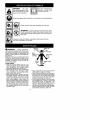 2
2
-
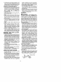 3
3
-
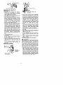 4
4
-
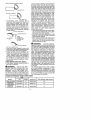 5
5
-
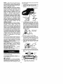 6
6
-
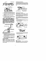 7
7
-
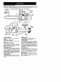 8
8
-
 9
9
-
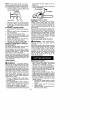 10
10
-
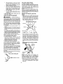 11
11
-
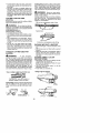 12
12
-
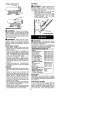 13
13
-
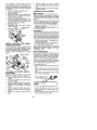 14
14
-
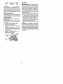 15
15
-
 16
16
-
 17
17
-
 18
18
-
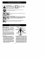 19
19
-
 20
20
-
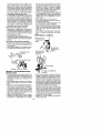 21
21
-
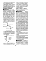 22
22
-
 23
23
-
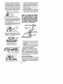 24
24
-
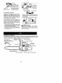 25
25
-
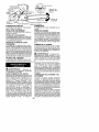 26
26
-
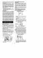 27
27
-
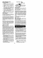 28
28
-
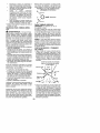 29
29
-
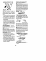 30
30
-
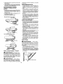 31
31
-
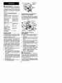 32
32
-
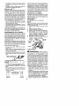 33
33
-
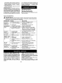 34
34
-
 35
35
-
 36
36


Poulan 1950 El manual del propietario
- Categoría
- Motosierras inalámbricas
- Tipo
- El manual del propietario
en otros idiomas
- English: Poulan 1950 Owner's manual
Artículos relacionados
-
 Poulan Pro PP4218AVX El manual del propietario
-
Poulan PP3816AV TYPE 1 El manual del propietario
-
 Poulan Pro PP4218 TYPE 1 El manual del propietario
-
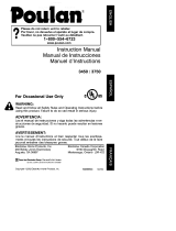 Poulan Pro 3450 El manual del propietario
-
Poulan Pro 2050 El manual del propietario
-
Poulan Pro 2250 LE El manual del propietario
-
 Poulan Pro PP4620AVHD El manual del propietario
-
Poulan 2155 El manual del propietario
-
 Poulan Pro PP4620AVL El manual del propietario
-
 Poulan Pro ES300 El manual del propietario


