
EN FR IT ES PT NL SV DK FI GR TR CZ PL HU SK SL EE LV LT DE
WRK
Betriebsanleitung

WRK
WRK
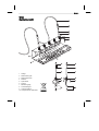
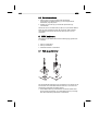
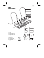
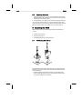
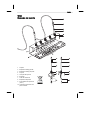
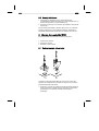
Geräteübersicht
1 Ablage
2 Reflow-Düse groß
3 Reflow-Düse klein
4 Dreibein
5 Spannhülse
6 Pick-Up
7 Markierungsring
8 Anschlussnippel
9 Vakuumschlauch
10 Saugeinsatz mit Hitzeschild

WRK 3-8
DE EN FR IT ES PT NL SV DK FI GR TR CZ PL HU SK SL EE LV LT
Inhalt
1
Zu dieser Anleitung .................................................................... 3
2 Zu Ihrer Sicherheit ..................................................................... 3
3 Lieferumfang .............................................................................. 4
4 Beschreibung WRK ................................................................... 4
5 WRK in Betrieb nehmen ............................................................ 5
6 WRK bedienen ........................................................................... 6
7 WRK pflegen und warten ........................................................... 8
8 Zubehör ..................................................................................... 8
9 Entsorgung ................................................................................ 8
10 Garantie ..................................................................................... 8
1 Zu dieser Anleitung
Wir danken Ihnen für das mit dem Kauf des Weller WRK erwiesene
Vertrauen. Bei der Fertigung wurden strengste
Qualitätsanforderungen zugrunde gelegt, die eine einwandfreie
Funktion des Gerätes sicherstellen.
Diese Anleitung enthält wichtige Informationen, um das WRK sicher
und sachgerecht in Betrieb zu nehmen, zu bedienen, zu warten und
einfache Störungen selbst zu beseitigen.
Z Lesen Sie diese Anleitung vollständig bevor Sie mit dem WRK
arbeiten.
Z Bewahren Sie diese Anleitung so auf, dass sie für alle Benutzer
zugänglich ist.
1.1 Mitgeltende Dokumente
− Betriebsanleitung Ihres Steuergerätes mit Begleitheft
Sicherheitshinweise
2 Zu Ihrer Sicherheit
Das WRK wurde entsprechend dem heutigen Stand der Technik und
den anerkannten sicherheitstechnischen Regeln hergestellt.
Trotzdem besteht die Gefahr von Personen- und Sachschäden,
wenn Sie die Sicherheitshinweise im beiliegenden Sicherheitsheft
des Steuergeräts sowie die Warnhinweise in dieser Anleitung nicht
beachten. Geben Sie das WRK an Dritte stets zusammen mit der
Betriebsanleitung weiter.
2.1 Bestimmungsgemäßer Gebrauch
Verwenden Sie das WRK ausschließlich gemäß dem in der
Betriebsanleitung angegebenen Zweck zum Lösen, Aufnehmen und
Absetzen von Chipbauteilen unter den hier angegebenen

4-8 WRK
Bedingungen. Der bestimmungsgemäße Gebrauch des WRK
schließt auch ein, dass
− Sie diese Anleitung beachten,
− Sie alle weiteren Begleitunterlagen beachten,
− Sie die nationalen Unfallverhütungsvorschriften am Einsatzort
beachten.
Für eigenmächtig vorgenommene Veränderungen am WRK wird
vom Hersteller keine Haftung übernommen.
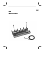
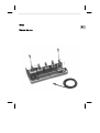
3 Lieferumfang
− WRK bestehend aus Ablage, Pick-Up (Ø 4,5 mm), Pick-Up
(Ø 10 mm), Dreibein, Reflow-Düsen groß (33x33 mm, 27x27 mm,
24x24 mm, 20x20 mm) und klein (18x18 mm, 15,5x15,5 mm,
12,5x12,5 mm, 10x10 mm)
− Je 3 Saugeinsätze für Ø 4,5 mm und Ø 10 mm
− 2 Vakuumschläuche mit Anschlussnippel
− Betriebsanleitung WRK Entlötset
4 Beschreibung WRK
Das Weller WRK Entlötset optimiert den Entlötvorgang und
ermöglicht Chipbauteile während des Entlötens präzise und
schonend aufzunehmen.
Mit Hilfe der verschiedenen Reflow-Düsen kann der Ablöse- und
Aufnahmevorgang für jede Bauteilgöße zwischen 3 mm und 30 mm
optimiert werden.
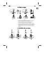
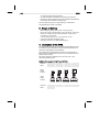
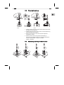
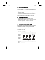
Die Reflow-Düsen sind für den Einsatz der Entlötwerkzeuge HAP 1
und HAP 200 geeignet.
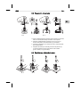
Geeignete Reflow-Düsen für HAP 1 und HAP 200
HAP 200
HAP 1
Kleine
Reflow-
Düsen
Große
Reflow-
Düsen
HAP 200
HAP 1

WRK 5-8
DE EN FR IT ES PT NL SV DK FI GR TR CZ PL HU SK SL EE LV LT
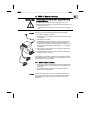
5 WRK in Betrieb nehmen
WARNUNG!
Verletzungsgefahr durch falsch angeschlossenen
Vakuumschlauch.
Bei falsch angeschlossenem Vakuumschlauch kann nach
Betätigen des HAP heiße Luft und flüssiges Lötzinn austreten und
zu Verletzungen führen.
Z Schließen Sie den Vakuumschlauch niemals am „Air“-Nippel
an!
Hinweis Beachten Sie auch die Betriebsanleitung Ihres Steuergeräts.
1. Das WRK sorgfältig auspacken.
2. Reflow-Düsen (2, 3), Dreibein (4) und Pick-Up (6) in der Ablage
(1) einhängen.
3. Steuergerät ausschalten.
4. Heißluft-Pencil (HAP) mit Luftschlauch am „Air“-Ausgang des
Steuergeräts anschließen und mit Anschlussstecker in die
richtige Anschlussbuchse der Reparaturstation einstecken und
durch kurze Rechtsdrehung verriegeln (HAP 1 nur mit Adapter
anschließen).
5. Pick-Up (6) mit Vakuumschlauch an den Pick-Up-Nippeln des
Steuergerätes anschließen.
6. Geeignete Reflow-Düse oder Dreibein am Pick-Up befestigen
(siehe Abschnitt 5.1 und 5.2).
Zum Abheben von kleinen Werkstücken mit dem Pick-Up können
große Reflow-Düsen , kleine Reflow-Düsen mit Dreibein oder das
Dreibein alleine verwendet werden
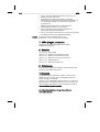
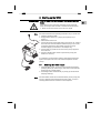
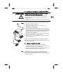
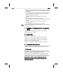
5.1 Reflow-Düse montieren
1. Pick-Up (Ø 10 mm) auf richtigen Sitz der Bauteile (Spannhülse
(5), Markierungsring (7) und Saugeinsatz mit Hitzeschild (10))
überprüfen.
2. Große Reflow-Düsen werden am Pick-Up (6) mit Hilfe der
Spannhülse (5) verschrauben.
Hinweis Die kleinen Reflow-Düsen werden nicht direkt mit dem Pick-Up
(Ø 4,5 mm) verschraubt. Hier sorgt das Dreibein für die richtige
Positionierung des Pick-Ups (Ø 4,5 mm) in der Düse und am
Werkstück.

6-8 WRK
A 1 B 1
5.2 Dreibein montieren
1. Pick-Up (Ø 4,5 mm) auf richtigen Sitz der Bauteile
(Spannhülse (5), Markierungsring (7) und Saugeinsatz mit
Hitzeschild (10)) überprüfen.
2. Dreibein (4) am Pick-Up (6) mit Hilfe der Spannhülse (5)
verschrauben.
Sie können das so montierte Pick-Up (Ø 4,5 mm) mit kleiner Reflow-
Düse (A) oder ohne Reflow-Düse (B) verwenden. Beim Arbeiten
ohne Reflow-Düse können Sie auch ein Pick-Up mit Ø 10 mm
verwenden.
6 WRK bedienen
Die Bedienung des WRK während des Entlötvorgangs gliedert sich
in 3 Schritte:
1. Pick-Up positionieren
2. Pick-Up vorbereiten
3. Werkstück entlöten und abheben
6.1 Pick-Up positionieren
Das anzuhebende Werkstück muss mindestens 2 mm kleiner als der
Durchmesser der verwendeten Reflow-Düse sein, sonst kann das
angehobene Werkstück beschädigt werden.
Z Große Reflow-Düse (A) oder Dreibein mit kleiner Reflow-Düse
(B) mit korrekt montiertem und vorbereitetem Pick-Up vorsichtig
über dem Werkstück positionieren und absetzen.

WRK 7-8
DE EN FR IT ES PT NL SV DK FI GR TR CZ PL HU SK SL EE LV LT
A 4 B 4
A 2
1
2
B 2
6.2 Pick-Up vorbereiten
1. Pick-Up mit montierter Reflow-Düse oder mit dem Dreibein
vorsichtig über dem Werkstück positionieren.
2. Pick-Up vorsichtig bis auf 3-5 mm über das Werkstück
herunterdrücken (1) ohne dieses zu beschädigen.
3. Vakuum am Steuergerät einschalten und Bauteil ansaugen.
4. Markierungsgummi in dieser Stellung nach unten schieben (2).
Der Markierungsring zeigt an ob das angesaugte Werkstück
angehoben (Gummi = oben) oder nicht angehoben (Gummi
unten) ist.
6.3 Werkstück entlöten und anheben
A 3 B 3

8-8 WRK
1. Pick-Up über dem Werkstück positionieren (siehe 6.1) und
Entlöten vorbereiten (siehe 6.2).
2. Heißluftwerkzeug seitlich durch die dafür vorgesehene
Düsenöffnung an das Werkstück heranführen und betätigen bis
sich das Werkstück ablöst und durch den Pick-Up-Stutzen
angehoben wird.
Markierungsring befindet sich nun in oberer Position.
3. Heißluftwerkzeug entfernen und ausschalten.
4. Pick-Up samt Düse und angesaugtem Werkstück auf
gewünschter Ablegefläche positionieren.
5. Pick-Up vorsichtig nach unten drücken und Vakuum ausschalten.
Das Werkstück wird auf der Ablegefläche abgelegt.
Hinweis Sie können auch ohne Reflow-Düse, z. B. bei
Werkstücken > 30 mm, mit dem HAP 200 arbeiten.
7 WRK pflegen und warten
Reinigen Sie das WRK regelmäßig mit einem milden
Edelstahlreinigungsmittel.
8 Zubehör
005 15 154 99 Ablage WRK
005 87 617 30 Entlötset 33x33/24x24 mit Pick-Up
005 87 617 31 Entlötset 27x27/20x20 mit Pick-Up
005 87 617 32 Entlötset 18/15,5/12,5/10 mit Pick-Up
005 87 617 39 WRK Zubehör Kit
005 87 617 40 WRK Vakuumpickup Set
9 Entsorgung
Entsorgen Sie ausgetauschte Geräteteile, Filter oder alte Geräte
gemäß den Vorschriften Ihres Landes.
10 Garantie
Die Mängelansprüche des Käufers verjähren in einem Jahr ab
Ablieferung an ihn. Dies gilt nicht für Rückgriffsansprüche des
Käufers nach §§ 478, 479 BGB.
Aus einer von uns abgegebenen Garantie haften wir nur, wenn die
Beschaffenheits- oder Haltbarkeitsgarantie von uns schriftlich und
unter Verwendung des Begriffs „Garantie“ abgegeben worden ist.
Technische Änderungen vorbehalten!
Die aktualisierten Betriebsanleitungen finden Sie unter
www.weller-tools.com.

EN FR IT ES PT NL SV DK FI GR TR CZ PL HU SK SL EE LV LT DE
WRK
Operating Instructions

WRK
WRK
Device Overview
1 Holder
2 Reflow nozzle, large
3 Reflow nozzle, small
4 Tripod
5 Clamping sleeve
6 Pick-up
7 Marker ring
8 Connecting nipple
9 Vacuum hose
10 Suction insert with heat
shield

WRK 3-8
DE EN FR IT ES PT NL SV DK FI GR TR CZ PL HU SK SL EE LV LT
Contents
1
About these instructions ............................................................ 3
2 For your safety ........................................................................... 3
3 Scope of delivery ....................................................................... 4
4 Description of the WRK ............................................................. 4
5 Starting up the WRK .................................................................. 5
6 Operating the WRK .................................................................... 6
7 Looking after and servicing the WRK ........................................ 8
8 Accessories ............................................................................... 8
9 Disposal ..................................................................................... 8
10 Warranty .................................................................................... 8
1 About these instructions
Thank you for the confidence you have shown in buying the Weller
WRK. The device has been manufactured in accordance with the
most rigorous quality standards, which ensure that the device
operates perfectly.
These instructions contain important information which will help you
to start up, operate and service the WRK safely and correctly as well
as to eliminate simple faults/malfunctions yourselves.
Z Read these instructions in their entirety before working with the
WRK.
Z Keep these instructions in a place that is accessible to all users.
1.1 Documents also applicable
− Operating instructions of your control unit and accompanying
Safety Information booklet
2 For your safety
The WRK has been manufactured in accordance with state-of-the-art
technology and recognised safety rules and regulations. There is
nevertheless the risk of personal injury and damage to property if
you fail to observe the safety information set out in the enclosed
booklet accompanying the control unit and the warnings given in
these instructions. Always pass on the WRK to third parties together
with these Operating Instructions.
2.1 Intended use
Use the WRK exclusively for the purpose indicated in the Operating
Instructions of releasing, accommodating and setting down chip
components under the conditions specified here. Intended use of the
WRK also includes the requirement that

4-8 WRK
− you read and follow these instructions,
− you read and follow all additional accompanying documents,
− observe the national accident-prevention regulations applicable at
the location where the device is being used.
The manufacturer accepts no responsibility for unauthorised
changes/alterations made to the WRK.
3 Scope of delivery
− WRK comprising holder, pick-up (dia. 4.5 mm), pick-up
− (dia.10 mm), tripod, reflow nozzles - large (33x33 mm, 27x27 mm,
24x24 mm, 20x20 mm) and small (18x18 mm, 15.5x15.5 mm,
12.5x12.5 mm, 10x10 mm)
− 3 suction inserts each for dia. 4.5 mm and dia. 10 mm
− 2 vacuum hoses with connecting nipple
− Operating Instructions for WRK desoldering set
4 Description of the WRK
The Weller WRK desoldering set optimises the desoldering process
and enables chip components to be accommodated precisely and
without being damaged during desoldering.
The release and accommodation procedure can be optimised for
each component size between 3 mm and 30 mm with the aid of the
different reflow nozzles.
The reflow nozzles are suitable for the use of the HAP 1 and
HAP 200 desoldering tools.
Suitable reflow nozzles for HAP 1 and HAP 200
HAP 200
HAP 1
Small
reflow
nozzles
Large
reflow
nozzles
HAP 200
HAP 1

WRK 5-8
DE EN FR IT ES PT NL SV DK FI GR TR CZ PL HU SK SL EE LV LT
5 Starting up the WRK
WARNING!
Risk of injury due to incorrectly connected vacuum
hose.
If the vacuum hose is incorrectly connected, hot air and liquid
solder can escape when the HAP is actuated and cause injuries.
Z Never connect the vacuum hose to the "Air“ nipple!
Note
A
lso read and observe the Operating Instructions of your control unit
1. Carefully unpack the WRK.
2. Engage reflow nozzles (2, 3), tripod (4) and pick-up (6) in
holder (1).
3. Switch off the control unit.
4. Connect the hot-air pencil (HAP) with air hose to the "Air“ outlet of
the control unit and insert with the attachment plug in the correct
connection socket of the repair station and lock by turning
clockwise slightly (connect HAP 1 with adapter only).
5. Connect pick-up (6) with vacuum hose to the pick-up nipples of
the control unit.
6. Secure a suitable reflow nozzle or tripod to the pick-up (see
Sections 5.1 and 5.2).
It is possible to use large reflow nozzles, small reflow nozzles with
tripod or the tripod on its own to lift off small workpieces with the
pick-up.
5.1 Mounting the reflow nozzle
1. Check the pick-up (dia. 10 mm) to ensure that the components
(clamping sleeve (5), marker ring (7) and suction insert with heat
shield (10)) are correctly seated.
2. Screw large reflow nozzles directly to pick-up (6) with the aid of
clamping sleeve (5).
Note The small reflow nozzles are not screwed directly to the pick-up (dia.
4.5 mm). Here the tripod ensures that the pick-up (dia. 4.5 mm) is
correctly positioned in the nozzle and on the workpiece.

6-8 WRK
A 1 B 1
5.2 Mounting the tripod
1. Check the pick-up (dia. 4.5 mm) to ensure that the components
(clamping sleeve (5), marker ring (7) and suction insert with heat
shield (10)) are correctly seated.
2. Screw tripod (4) to pick-up (6) with the aid of clamping sleeve (5).
You can use the pick-up (dia. 4.5 mm) mounted in this way with a
small reflow nozzle (A) or without a reflow nozzle (B). When working
without a reflow nozzle, you can also use a 10 mm dia. pick-up.
6 Operating the WRK
WRK operation during the desoldering procedure is divided into
3 steps:
1. Positioning the pick-up
2. Preparing the pick-up
3. Desoldering and lifting off the workpiece
6.1 Positioning the pick-up
The workpiece to be raised must be at least 2 mm smaller than the
diameter of the reflow nozzle used, otherwise the raised workpiece
may be damaged.
Z Carefully position large reflow nozzle (A) or tripod with small
reflow nozzle (B) with the correctly mounted and prepared pick-
up over the workpiece and set down.

WRK 7-8
DE EN FR IT ES PT NL SV DK FI GR TR CZ PL HU SK SL EE LV LT
A 4 B 4
A 2
1
2
B 2
6.2 Preparing the pick-up
1. Carefully position the pick-up with mounted reflow nozzle or with
the tripod over the workpiece.
2. Carefully press the pick-up down 3-5 mm over the workpiece (1)
without damaging the workpiece.
3. Switch on the vacuum on the control unit and subject the
component to suction.
4. Slide the rubber marker in this position downwards (2).
The marker ring indicates whether the workpiece subjected to
suction is raised (rubber = at top) or not raised
(rubber = at bottom).
6.3 Desoldering and lifting off the workpiece
A 3 B 3

8-8 WRK
1. Position the pick-up over the workpiece (see 6.1) and prepare
desoldering (see 6.2).
2. Feed the hot-air tool from the side through the designated nozzle
opening up to the workpiece and actuate the tool until the
workpiece is detached and raised by the pick-up fitting.
The marker ring is now in the upper position.
3. Remove the hot-air tool and switch off.
4. Position the pick-up together with the nozzle and the workpiece
subjected to suction on the desired set-down surface.
5. Carefully press the pick-up downwards and switch off the
vacuum.
The workpiece is set down on the set-down surface.
Note You can also work with the HAP 200 without a reflow nozzle, e.g. in
the case of workpieces > 30 mm.
7 Looking after and servicing the WRK
Clean the WRK on a regular basis with a mild special-steel cleaning
agent.
8 Accessories
005 15 15 499 WRK holder
005 87 617 30 Desoldering set 33x33/24x24 with pick-up
005 87 617 31 Desoldering set 27x27/20x20 with pick-up
005 87 617 32 Desoldering set 18/15.5/12.5/10 with pick-up
005 87 617 39 WRK ACCESSORY KIT
005 87 617 40 WRK VACUUM PICK-UP SET
9 Disposal
Dispose of replaced equipment parts, filters or old devices in
accordance with the rules and regulations applicable in your country.
10 Warranty
Claims by the buyer for physical defects are time-barred after a
period of one year from delivery to the buyer. This does not apply to
claims by the buyer for indemnification in accordance with
§§ 478, 479 BGB (German Federal Law Gazette).
We shall only be liable arising from a warranty furnished by us if the
quality or durability warranty has been furnished by use in writing
and using the term "Warranty“.
Subject to technical alterations and amendments!
See the updated operating instructions at www.weller-tools.com.

EN ES IT ES PT NL SV DK FI GR TR CZ PL HU SK SL EE LV LT DE
WRK
Manual de uso

WRK
WRK
Esquema del aparato
1 Soporte
2 Boquilla de reflujo grande
3 Boquilla de reflujo pequeña
4 Trípode
5 Casquillo de sujeción
6 Extractor
7 Anilla de referencia
8 Boquilla de empalme
9 Tubo flexible de aspiración
(vacío)
10 Ventosa de aspiración con
placa caliente

WRK 3-8
DE EN ES IT ES PT NL SV DK FI GR TR CZ PL HU SK SL EE LV LT
Índice
1
Información breve sobre este manual ....................................... 3
2 Por su propia seguridad ............................................................. 3
3 Piezas suministradas ................................................................. 4
4 Descripción de la estación WRK ............................................... 4
5 Puesta en marcha de la estación WRK ..................................... 5
6 Manejo de la estación WRK ...................................................... 6
7 Cuidado y mantenimiento de la estación WRK ......................... 8
8 Accesorios ................................................................................. 8
9 Eliminación de residuos ............................................................. 8
10 Garantía ..................................................................................... 8
1 Información breve sobre este manual
Le agradecemos mucho la compra de la estación Weller WRK y la
confianza depositada en nosotros. La fabricación de este aparato
está sometida a los más rigurosos controles de calidad para
garantizar un perfecto funcionamiento del mismo.
Este manual de uso contiene información importante para poder
poner en marcha y manejar de forma segura y adecuada la estación
WRK, así como para realizar las tareas de mantenimiento
adecuadas e incluso reparar pequeñas averías.
Z Lea el manual de uso completo antes de comenzar a trabajar con
la estación WRK.
Z Mantenga este manual de uso en un lugar al que puedan
acceder todos los usuarios del aparato.
1.1 Otros documentos aplicables
− Manual de uso de la unidad de control con el folleto con las
normas de seguridad
2 Por su propia seguridad
La estación WRK ha sido fabricada según los últimos avances
tecnológicos y de conformidad con la normativa de seguridad
técnica. No obstante, existe riesgo de que se produzcan daños
personales o materiales si no se respetan las instrucciones de
seguridad que figuran en el folleto de seguridad adjunto de la unidad
de control, así como las advertencias de este manual de uso. La
estación WRK debe entregarse siempre a terceros unto con el
manual de uso.

4-8 WRK
2.1 Utilización reglamentaria
Utilice la estación WRK exclusivamente para los fines indicados en
el manual de uso, pasa soltar, tomar y retirar "chips" en las
condiciones indicadas. El uso correcto y adecuado del WRK implica
también que
− siga las instrucciones de este manual,
− que siga las instrucciones de todos los documentos que
acompañan al aparato,
− que respete la normativa nacional vigente para la prevención de
accidentes laborales.
El fabricante no asume ninguna responsabilidad en caso de que se
realicen modificaciones en la estación WRK por cuenta propia.
3 Piezas suministradas
− La estación WRK se compone de un soporte, extractor
(Ø 4,5 mm), extractor (Ø 10 mm), trípode, boquilla de reflujo
grande (33x33 mm, 27x27 mm, 24x24 mm, 20x20 mm) y pequeña
(18x18 mm, 15,5x15,5 mm, 12,5x12,5 mm, 10x10 mm)
− 3 ventosas de aspiración para Ø 4,5 mm y Ø 10 mm
− 2 tubos flexibles de aspiración con boquilla de empalme
− Manual de uso de la estación WRK set de desoldar
4 Descripción de la estación WRK
El set de desoldar Weller WRK optimiza la operación de desoldaura
y permite retirar con precisión y cuidado los chips al desoldar.
Gracias a las diferentes boquillas de reflujo es posible soltar y retirar
de forma más sencilla los chips de entre 3 mm y 30 mm.
Las boquillas de reflujo se pueden utilizar con las herramientas de
desoldar HAP 1 y HAP 200.
Boquillas de reflujo aptas para HAP 1 y HAP 200
HAP 200
HAP 1
Boquillas
de reflujo
pequeñas
Boquillas
de reflujo
grandes
HAP 200
HAP 1

WRK 5-8
DE EN ES IT ES PT NL SV DK FI GR TR CZ PL HU SK SL EE LV LT
5 Puesta en marcha de la estación WRK
¡ADVERTENCIA!
Peligro de sufrir lesiones si se conecta de forma
errónea el tubo flexible de aspiración.
Si se conecta erróneamente el tubo flexible de aspiración al
conectar el HAP puede salir aire caliente y estaño fundido, y
provocar lesiones.
Z ¡No conecte nunca el tubo flexible de aspiración en la boquilla
"Air"!
Nota Siga las instrucciones del manual de uso de la unidad de control.
1. Desembale el WRK con cuidado.
2. Coloque las boquillas de reflujo (2, 3), el trípode (4) y el
extractor (6) en el soporte (1).
3. Desconecte la unidad de control.
4. Conectar el lápiz de aire caliente (HAP) con el tubo flexible de
aire en la toma de aire "Air" de la unidad de control e introducir la
boquilla macho en la toma de la estación de reparación y fijarla
girándola ligeramente hacia la derecha (conectar el HAP 1
únicamente con un adaptador).
5. Conectar el extractor (6) con el tubo flexible de aspiración en la
boquilla del extractor de la unidad de control.
6. Fijar la boquilla de reflujo adecuada o el trípode en el extractor
(véase el apartado 5.1 y 5.2).
Para poder retirar piezas pequeñas con el extractor se pueden
utilizar las boquillas de reflujo grandes o pequeñas con el trípode o
bien solamente el trípode.
5.1 Montar la boquilla de reflujo
1. Comprobar que el extractor (Ø 10 mm) está colocado
correctamente (casquillo de sujeción (5), anillo de referencia (7) y
ventosa de aspiración con placa caliente (10)).
2. Las boquillas de reflujo grandes se enroscan directamente en el
extractor (6) mediante el casquillo de sujeción (5).
Nota Las boquillas de reflujo no se enroscan directamente con el
extractor (Ø 4,5 mm). En este caso, el trípode se encarga del
posicionamiento adecuado del extractor (Ø 4,5 mm) en la boquilla y
en la pieza a retirar.

6-8 WRK
A 1 B 1
5.2 Montaje del trípode
1. Comprobar que el extractor (Ø 4,5 mm) está colocado
correctamente (casquillo de sujeción (5), anillo de referencia (7) y
boquilla de aspiración con placa caliente (10)).
2. Enroscar el trípode (4) en el extractor (6) mediante el casquillo de
sujeción (5).
De esta forma podrá utilizar el extractor (Ø 4,5 mm) con la boquilla
de reflujo pequeña (A) o sin boquilla de reflujo (B). Al trabajar sin
boquilla de reflujo también podrá utilizar un extractor de Ø 10 mm.
6 Manejo de la estación WRK
El manejo de WRK para desoldar consiste en tres pasos:
1. Posicionar el extractor
2. Preparar el extractor
3. Desoldar y retirar la pieza
6.1 Posicionamiento del extractor
La pieza que se desea retirar debe ser como mínimo 2 mm más
pequeña que el diámetro de la boquilla de reflujo, de lo contrario la
pieza retirada podría sufrir daños.
Z Posicionar y colocar con cuidado la boquilla de reflujo grande (A)
sobre la pieza que se desea retirar (o el trípode con la boquilla
pequeña (B) con el extractor montado correctamente y
preparado).

WRK 7-8
DE EN ES IT ES PT NL SV DK FI GR TR CZ PL HU SK SL EE LV LT
A 4 B 4
A 2
1
2
B 2
6.2 Preparación del extractor
1.Colocar cuidadosamente el extractor sobre la pieza que se desea
retirar con la boquilla de reflujo montada o con el trípode.
2. Presionar cuidadosamente el extractor a unos 3-5 mm por
encima de la pieza que se desea retirar (1) sin dañarla.
3. Conectar la aspiración en la unidad de control y aspirar la pieza
que se desea retirar.
4. Desplazar hacia abajo la anilla de goma en esta posición (2).
La anilla de referencia indica si la pieza ha sido retirada
(goma = arriba) o no (goma abajo).
6.3 Desoldaura y retirada de la pieza
A 3 B 3

8-8 WRK
1. Colocar el extractor sobre la pieza que se desea retirar (véase el
apartado 6.1) y preparar la operación de desoldadura (véase el
apartado 6.2).
2. Acercar el lápiz de aire caliente a la pieza por la abertura lateral y
conectarlo hasta que se suelte la pieza que se desea retirar y
pueda ser retirada por el extractor.
La anilla de referencia se encuentra ahora en la posición
superior.
3. Retirar el lápiz de aire caliente y desconectarlo.
4. Colocar el extractor con la boquilla y la pieza retirada en el lugar
deseado.
5. Presionar cuidadosamente el extractor y desconectar la
aspiración (vacío).
La pieza retirada es depositada en el lugar deseado.
Nota También puede trabajar sin boquilla de reflujo, p. ej. con el HAP 200
para retirar piezas > 30 mm.
7 Cuidado y mantenimiento de la estación
WRK
Limpiar periódicamente la estación WRK con un producto de
limpieza para acero inoxidable.
8 Accesorios
005 15 154 99 Soporte WRK
005 87 617 30 Set de desoldar 33x33/24x24 con extractor
005 87 617 31 Set de desoldar 27x27/20x20 con extractor
005 87 617 32 Set de desoldar 18/15,5/12,5/10 con extractor
005 87 617 39 Kit de accesorios WRK
005 87 617 40 Juego de recogida y aspirado por vacío WRK
9 Eliminación de residuos
Elimine los componentes y filtros cambiados en el aparato, así como
aparatos en desuso, siguiendo la normativa vigente en su país.
10 Garantía
Los derechos de reclamación del comprador prescriben uno año
después de la compra. Sólo válido para los derechos del comprador
según el art. §§ 478, 479 BGB (código civil alemán).
Únicamente nos responsabilizamos de los derechos de garantía
cuando la garantía de compra y vida útil del aparato haya sido
entregada por nosotros por escrito y utilizando el término "Garantía".
¡Reservado el derecho a realizar modificaciones técnicas!
Encontrará los manuales de instrucciones actualizados en
www.weller-tools.com.

G E R M
A
N Y
Weller Tools GmbH
Carl-Benz-Str. 2
74354 Besigheim
Phone: +49 (0) 7143 580-0
Fax: +49 (0) 7143 580-108
G R E
A
T BRIT
A
IN
Apex Tool Group
(UK Operation) Ltd
4
th
Floor Pennine House
Washington, Tyne & Wear
NE37 1LY
Phone: +44 (0) 191 419 7700
Fax: +44 (0) 191 417 9421
FR
A
NCE
Apex Tool France S.N.C.
25 Av. Maurice Chevalier BP 46
77832 Ozoir-la-Ferrière Cedex
Phone: +33 (0) 1.64.43.22.00
Fax: +33 (0) 1.64.43.21.62
I T
A
L Y
Apex Tool S.r.I.
Viale Europa 80
20090 Cusago (MI)
Phone: +39 (02) 9033101
Fax: +39 (02) 90394231
S W I T Z E R L
A
ND
Apex Tool Switzerland Sárl
Rue de la Roselière 8
1400 Yverdon-les-Bains
Phone: +41 (0) 24 426 12 06
Fax: +41 (0) 24 425 09 77
A
U S T R
A
L I
A
Apex Tools-Australia
P.O. Box 366
519 Nurigong Street
Albury, N. S. W. 2640
Phone: +61 (2) 6058-0300
Fax: +61 (2) 6021-7403
C
A
N
A
D
A
Apex Tools - Canada
5925 McLaughlin Rd.
Mississauga
Ontario L5R 1B8
Phone: +1 (905) 501-4785
Fax: +1 (905) 387-2640
CHIN
A
Apex Tool Group
A-8 Building, No. 38 Dongsheng
Road
Heqing Industrial Park, Pudong
Shanghai 201201
Phone: +86 (21) 60 88 02 88
Fax: +86 (21) 60 88 02 89
U S A
Apex Tool Group, LLC
14600 York Rd. Suite A
Sparks, MD 21152
Phone: +1 (800) 688-8949
Fax: +1
(
800
)
234-0472
www.weller-tools.com
Weller
®
is a registered Trademark and registered Design of Apex Tool Group, LLC
© 2013, Apex Tool Group, LLC
T005 57 056 05 / 08.2013
T005 57 056 04 / 02.2012
Transcripción de documentos
LV EE SL SK HU PL CZ TR GR FI DK SV NL PT ES IT Betriebsanleitung LT FR EN WRK DE WRK WRK Geräteübersicht 1 2 3 4 5 6 7 8 9 10 Ablage Reflow-Düse groß Reflow-Düse klein Dreibein Spannhülse Pick-Up Markierungsring Anschlussnippel Vakuumschlauch Saugeinsatz mit Hitzeschild Inhalt 1 Zu dieser Anleitung .................................................................... 3 DE 3-8 EN WRK 3 Lieferumfang .............................................................................. 4 FR 2 Zu Ihrer Sicherheit ..................................................................... 3 Z Lesen Sie diese Anleitung vollständig bevor Sie mit dem WRK arbeiten. Z Bewahren Sie diese Anleitung so auf, dass sie für alle Benutzer zugänglich ist. 1.1 Mitgeltende Dokumente − Betriebsanleitung Ihres Steuergerätes mit Begleitheft Sicherheitshinweise 2 Zu Ihrer Sicherheit ES PT NL SV DK 2.1 Bestimmungsgemäßer Gebrauch LV Verwenden Sie das WRK ausschließlich gemäß dem in der Betriebsanleitung angegebenen Zweck zum Lösen, Aufnehmen und Absetzen von Chipbauteilen unter den hier angegebenen LT Das WRK wurde entsprechend dem heutigen Stand der Technik und den anerkannten sicherheitstechnischen Regeln hergestellt. Trotzdem besteht die Gefahr von Personen- und Sachschäden, wenn Sie die Sicherheitshinweise im beiliegenden Sicherheitsheft des Steuergeräts sowie die Warnhinweise in dieser Anleitung nicht beachten. Geben Sie das WRK an Dritte stets zusammen mit der Betriebsanleitung weiter. FI Diese Anleitung enthält wichtige Informationen, um das WRK sicher und sachgerecht in Betrieb zu nehmen, zu bedienen, zu warten und einfache Störungen selbst zu beseitigen. GR Wir danken Ihnen für das mit dem Kauf des Weller WRK erwiesene Vertrauen. Bei der Fertigung wurden strengste Qualitätsanforderungen zugrunde gelegt, die eine einwandfreie Funktion des Gerätes sicherstellen. TR 1 Zu dieser Anleitung CZ 10 Garantie ..................................................................................... 8 PL 9 Entsorgung ................................................................................ 8 HU 8 Zubehör ..................................................................................... 8 SK 7 WRK pflegen und warten ........................................................... 8 SL 6 WRK bedienen........................................................................... 6 EE 5 WRK in Betrieb nehmen ............................................................ 5 IT 4 Beschreibung WRK ................................................................... 4 4-8 WRK Bedingungen. Der bestimmungsgemäße Gebrauch des WRK schließt auch ein, dass − Sie diese Anleitung beachten, − Sie alle weiteren Begleitunterlagen beachten, − Sie die nationalen Unfallverhütungsvorschriften am Einsatzort beachten. Für eigenmächtig vorgenommene Veränderungen am WRK wird vom Hersteller keine Haftung übernommen. 3 Lieferumfang − WRK bestehend aus Ablage, Pick-Up (Ø 4,5 mm), Pick-Up (Ø 10 mm), Dreibein, Reflow-Düsen groß (33x33 mm, 27x27 mm, 24x24 mm, 20x20 mm) und klein (18x18 mm, 15,5x15,5 mm, 12,5x12,5 mm, 10x10 mm) − Je 3 Saugeinsätze für Ø 4,5 mm und Ø 10 mm − 2 Vakuumschläuche mit Anschlussnippel − Betriebsanleitung WRK Entlötset 4 Beschreibung WRK Das Weller WRK Entlötset optimiert den Entlötvorgang und ermöglicht Chipbauteile während des Entlötens präzise und schonend aufzunehmen. Mit Hilfe der verschiedenen Reflow-Düsen kann der Ablöse- und Aufnahmevorgang für jede Bauteilgöße zwischen 3 mm und 30 mm optimiert werden. Die Reflow-Düsen sind für den Einsatz der Entlötwerkzeuge HAP 1 und HAP 200 geeignet. Geeignete Reflow-Düsen für HAP 1 und HAP 200 HAP 200 HAP 1 Kleine ReflowDüsen Große ReflowDüsen HAP 200 HAP 1 Vakuumschlauch. Bei falsch angeschlossenem Vakuumschlauch kann nach Betätigen des HAP heiße Luft und flüssiges Lötzinn austreten und zu Verletzungen führen. ES Z Schließen Sie den Vakuumschlauch niemals am „Air“-Nippel an! EN WARNUNG! Verletzungsgefahr durch falsch angeschlossenen FR 5 WRK in Betrieb nehmen DE 5-8 IT WRK Zum Abheben von kleinen Werkstücken mit dem Pick-Up können große Reflow-Düsen , kleine Reflow-Düsen mit Dreibein oder das Dreibein alleine verwendet werden NL SV DK FI GR TR 1. Das WRK sorgfältig auspacken. 2. Reflow-Düsen (2, 3), Dreibein (4) und Pick-Up (6) in der Ablage (1) einhängen. 3. Steuergerät ausschalten. 4. Heißluft-Pencil (HAP) mit Luftschlauch am „Air“-Ausgang des Steuergeräts anschließen und mit Anschlussstecker in die richtige Anschlussbuchse der Reparaturstation einstecken und durch kurze Rechtsdrehung verriegeln (HAP 1 nur mit Adapter anschließen). 5. Pick-Up (6) mit Vakuumschlauch an den Pick-Up-Nippeln des Steuergerätes anschließen. 6. Geeignete Reflow-Düse oder Dreibein am Pick-Up befestigen (siehe Abschnitt 5.1 und 5.2). PT Beachten Sie auch die Betriebsanleitung Ihres Steuergeräts. CZ Hinweis HU SK SL EE Die kleinen Reflow-Düsen werden nicht direkt mit dem Pick-Up (Ø 4,5 mm) verschraubt. Hier sorgt das Dreibein für die richtige Positionierung des Pick-Ups (Ø 4,5 mm) in der Düse und am Werkstück. LV Hinweis LT 1. Pick-Up (Ø 10 mm) auf richtigen Sitz der Bauteile (Spannhülse (5), Markierungsring (7) und Saugeinsatz mit Hitzeschild (10)) überprüfen. 2. Große Reflow-Düsen werden am Pick-Up (6) mit Hilfe der Spannhülse (5) verschrauben. PL 5.1 Reflow-Düse montieren 6-8 WRK 5.2 Dreibein montieren 1. Pick-Up (Ø 4,5 mm) auf richtigen Sitz der Bauteile (Spannhülse (5), Markierungsring (7) und Saugeinsatz mit Hitzeschild (10)) überprüfen. 2. Dreibein (4) am Pick-Up (6) mit Hilfe der Spannhülse (5) verschrauben. Sie können das so montierte Pick-Up (Ø 4,5 mm) mit kleiner ReflowDüse (A) oder ohne Reflow-Düse (B) verwenden. Beim Arbeiten ohne Reflow-Düse können Sie auch ein Pick-Up mit Ø 10 mm verwenden. 6 WRK bedienen Die Bedienung des WRK während des Entlötvorgangs gliedert sich in 3 Schritte: 1. Pick-Up positionieren 2. Pick-Up vorbereiten 3. Werkstück entlöten und abheben 6.1 Pick-Up positionieren A1 B1 Das anzuhebende Werkstück muss mindestens 2 mm kleiner als der Durchmesser der verwendeten Reflow-Düse sein, sonst kann das angehobene Werkstück beschädigt werden. Z Große Reflow-Düse (A) oder Dreibein mit kleiner Reflow-Düse (B) mit korrekt montiertem und vorbereitetem Pick-Up vorsichtig über dem Werkstück positionieren und absetzen. WRK 7-8 FR EN DE 6.2 Pick-Up vorbereiten 1 NL PT ES IT 2 Der Markierungsring zeigt an ob das angesaugte Werkstück angehoben (Gummi = oben) oder nicht angehoben (Gummi unten) ist. A4 DK FI B4 LV B3 LT A3 EE SL SK HU PL CZ TR 6.3 Werkstück entlöten und anheben SV B2 1. Pick-Up mit montierter Reflow-Düse oder mit dem Dreibein vorsichtig über dem Werkstück positionieren. 2. Pick-Up vorsichtig bis auf 3-5 mm über das Werkstück herunterdrücken (1) ohne dieses zu beschädigen. 3. Vakuum am Steuergerät einschalten und Bauteil ansaugen. 4. Markierungsgummi in dieser Stellung nach unten schieben (2). GR A2 8-8 WRK 1. Pick-Up über dem Werkstück positionieren (siehe 6.1) und Entlöten vorbereiten (siehe 6.2). 2. Heißluftwerkzeug seitlich durch die dafür vorgesehene Düsenöffnung an das Werkstück heranführen und betätigen bis sich das Werkstück ablöst und durch den Pick-Up-Stutzen angehoben wird. Markierungsring befindet sich nun in oberer Position. 3. Heißluftwerkzeug entfernen und ausschalten. 4. Pick-Up samt Düse und angesaugtem Werkstück auf gewünschter Ablegefläche positionieren. 5. Pick-Up vorsichtig nach unten drücken und Vakuum ausschalten. Das Werkstück wird auf der Ablegefläche abgelegt. Hinweis Sie können auch ohne Reflow-Düse, z. B. bei Werkstücken > 30 mm, mit dem HAP 200 arbeiten. 7 WRK pflegen und warten Reinigen Sie das WRK regelmäßig mit einem milden Edelstahlreinigungsmittel. 8 Zubehör 005 15 154 99 Ablage WRK 005 87 617 30 Entlötset 33x33/24x24 mit Pick-Up 005 87 617 31 Entlötset 27x27/20x20 mit Pick-Up 005 87 617 32 Entlötset 18/15,5/12,5/10 mit Pick-Up 005 87 617 39 WRK Zubehör Kit 005 87 617 40 WRK Vakuumpickup Set 9 Entsorgung Entsorgen Sie ausgetauschte Geräteteile, Filter oder alte Geräte gemäß den Vorschriften Ihres Landes. 10 Garantie Die Mängelansprüche des Käufers verjähren in einem Jahr ab Ablieferung an ihn. Dies gilt nicht für Rückgriffsansprüche des Käufers nach §§ 478, 479 BGB. Aus einer von uns abgegebenen Garantie haften wir nur, wenn die Beschaffenheits- oder Haltbarkeitsgarantie von uns schriftlich und unter Verwendung des Begriffs „Garantie“ abgegeben worden ist. Technische Änderungen vorbehalten! Die aktualisierten Betriebsanleitungen finden Sie unter www.weller-tools.com. LV EE SL SK HU PL CZ TR GR FI DK SV NL PT ES IT Operating Instructions LT FR EN WRK DE WRK WRK Device Overview 1 2 3 4 5 6 7 8 9 10 Holder Reflow nozzle, large Reflow nozzle, small Tripod Clamping sleeve Pick-up Marker ring Connecting nipple Vacuum hose Suction insert with heat shield Contents 1 About these instructions ............................................................ 3 DE 3-8 EN WRK 3 Scope of delivery ....................................................................... 4 FR 2 For your safety ........................................................................... 3 Z Read these instructions in their entirety before working with the WRK. Z Keep these instructions in a place that is accessible to all users. 1.1 Documents also applicable − Operating instructions of your control unit and accompanying Safety Information booklet 2 For your safety The WRK has been manufactured in accordance with state-of-the-art technology and recognised safety rules and regulations. There is nevertheless the risk of personal injury and damage to property if you fail to observe the safety information set out in the enclosed booklet accompanying the control unit and the warnings given in these instructions. Always pass on the WRK to third parties together with these Operating Instructions. 2.1 Intended use Use the WRK exclusively for the purpose indicated in the Operating Instructions of releasing, accommodating and setting down chip components under the conditions specified here. Intended use of the WRK also includes the requirement that ES PT NL SV DK FI GR These instructions contain important information which will help you to start up, operate and service the WRK safely and correctly as well as to eliminate simple faults/malfunctions yourselves. TR Thank you for the confidence you have shown in buying the Weller WRK. The device has been manufactured in accordance with the most rigorous quality standards, which ensure that the device operates perfectly. CZ About these instructions PL 1 HU 10 Warranty .................................................................................... 8 SK 9 Disposal ..................................................................................... 8 SL 8 Accessories ............................................................................... 8 EE 7 Looking after and servicing the WRK ........................................ 8 LV 6 Operating the WRK .................................................................... 6 LT 5 Starting up the WRK .................................................................. 5 IT 4 Description of the WRK ............................................................. 4 4-8 WRK − you read and follow these instructions, − you read and follow all additional accompanying documents, − observe the national accident-prevention regulations applicable at the location where the device is being used. The manufacturer accepts no responsibility for unauthorised changes/alterations made to the WRK. 3 Scope of delivery − WRK comprising holder, pick-up (dia. 4.5 mm), pick-up − (dia.10 mm), tripod, reflow nozzles - large (33x33 mm, 27x27 mm, 24x24 mm, 20x20 mm) and small (18x18 mm, 15.5x15.5 mm, 12.5x12.5 mm, 10x10 mm) − 3 suction inserts each for dia. 4.5 mm and dia. 10 mm − 2 vacuum hoses with connecting nipple − Operating Instructions for WRK desoldering set 4 Description of the WRK The Weller WRK desoldering set optimises the desoldering process and enables chip components to be accommodated precisely and without being damaged during desoldering. The release and accommodation procedure can be optimised for each component size between 3 mm and 30 mm with the aid of the different reflow nozzles. The reflow nozzles are suitable for the use of the HAP 1 and HAP 200 desoldering tools. Suitable reflow nozzles for HAP 1 and HAP 200 HAP 200 HAP 1 Small reflow nozzles Large reflow nozzles HAP 200 HAP 1 WARNING! Risk of injury due to incorrectly connected vacuum hose. If the vacuum hose is incorrectly connected, hot air and liquid solder can escape when the HAP is actuated and cause injuries. EN 5 Starting up the WRK DE 5-8 FR WRK 2. Screw large reflow nozzles directly to pick-up (6) with the aid of clamping sleeve (5). Note The small reflow nozzles are not screwed directly to the pick-up (dia. 4.5 mm). Here the tripod ensures that the pick-up (dia. 4.5 mm) is correctly positioned in the nozzle and on the workpiece. PT NL SV DK FI GR TR CZ PL 1. Check the pick-up (dia. 10 mm) to ensure that the components (clamping sleeve (5), marker ring (7) and suction insert with heat shield (10)) are correctly seated. HU Mounting the reflow nozzle SK 5.1 SL It is possible to use large reflow nozzles, small reflow nozzles with tripod or the tripod on its own to lift off small workpieces with the pick-up. EE 1. Carefully unpack the WRK. 2. Engage reflow nozzles (2, 3), tripod (4) and pick-up (6) in holder (1). 3. Switch off the control unit. 4. Connect the hot-air pencil (HAP) with air hose to the "Air“ outlet of the control unit and insert with the attachment plug in the correct connection socket of the repair station and lock by turning clockwise slightly (connect HAP 1 with adapter only). 5. Connect pick-up (6) with vacuum hose to the pick-up nipples of the control unit. 6. Secure a suitable reflow nozzle or tripod to the pick-up (see Sections 5.1 and 5.2). LV Also read and observe the Operating Instructions of your control unit LT Note ES IT Z Never connect the vacuum hose to the "Air“ nipple! 6-8 WRK 5.2 Mounting the tripod 1. Check the pick-up (dia. 4.5 mm) to ensure that the components (clamping sleeve (5), marker ring (7) and suction insert with heat shield (10)) are correctly seated. 2. Screw tripod (4) to pick-up (6) with the aid of clamping sleeve (5). You can use the pick-up (dia. 4.5 mm) mounted in this way with a small reflow nozzle (A) or without a reflow nozzle (B). When working without a reflow nozzle, you can also use a 10 mm dia. pick-up. 6 Operating the WRK WRK operation during the desoldering procedure is divided into 3 steps: 1. Positioning the pick-up 2. Preparing the pick-up 3. Desoldering and lifting off the workpiece 6.1 Positioning the pick-up A1 B1 The workpiece to be raised must be at least 2 mm smaller than the diameter of the reflow nozzle used, otherwise the raised workpiece may be damaged. Z Carefully position large reflow nozzle (A) or tripod with small reflow nozzle (B) with the correctly mounted and prepared pickup over the workpiece and set down. WRK 7-8 Preparing the pick-up FR EN DE 6.2 1 NL PT ES IT 2 Desoldering and lifting off the workpiece B3 A4 B4 DK FI LT A3 LV EE SL SK HU PL CZ 6.3 GR The marker ring indicates whether the workpiece subjected to suction is raised (rubber = at top) or not raised (rubber = at bottom). SV B2 1. Carefully position the pick-up with mounted reflow nozzle or with the tripod over the workpiece. 2. Carefully press the pick-up down 3-5 mm over the workpiece (1) without damaging the workpiece. 3. Switch on the vacuum on the control unit and subject the component to suction. 4. Slide the rubber marker in this position downwards (2). TR A2 8-8 WRK 1. Position the pick-up over the workpiece (see 6.1) and prepare desoldering (see 6.2). 2. Feed the hot-air tool from the side through the designated nozzle opening up to the workpiece and actuate the tool until the workpiece is detached and raised by the pick-up fitting. The marker ring is now in the upper position. 3. Remove the hot-air tool and switch off. 4. Position the pick-up together with the nozzle and the workpiece subjected to suction on the desired set-down surface. 5. Carefully press the pick-up downwards and switch off the vacuum. The workpiece is set down on the set-down surface. Note You can also work with the HAP 200 without a reflow nozzle, e.g. in the case of workpieces > 30 mm. 7 Looking after and servicing the WRK Clean the WRK on a regular basis with a mild special-steel cleaning agent. 8 Accessories 005 15 15 499 WRK holder 005 87 617 30 Desoldering set 33x33/24x24 with pick-up 005 87 617 31 Desoldering set 27x27/20x20 with pick-up 005 87 617 32 Desoldering set 18/15.5/12.5/10 with pick-up 005 87 617 39 WRK ACCESSORY KIT 005 87 617 40 WRK VACUUM PICK-UP SET 9 Disposal Dispose of replaced equipment parts, filters or old devices in accordance with the rules and regulations applicable in your country. 10 Warranty Claims by the buyer for physical defects are time-barred after a period of one year from delivery to the buyer. This does not apply to claims by the buyer for indemnification in accordance with §§ 478, 479 BGB (German Federal Law Gazette). We shall only be liable arising from a warranty furnished by us if the quality or durability warranty has been furnished by use in writing and using the term "Warranty“. Subject to technical alterations and amendments! See the updated operating instructions at www.weller-tools.com. LV EE SL SK HU PL CZ TR GR FI DK SV NL PT ES IT Manual de uso LT ES EN WRK DE WRK WRK Esquema del aparato 1 2 3 4 5 6 7 8 9 Soporte Boquilla de reflujo grande Boquilla de reflujo pequeña Trípode Casquillo de sujeción Extractor Anilla de referencia Boquilla de empalme Tubo flexible de aspiración (vacío) 10 Ventosa de aspiración con placa caliente Índice 1 Información breve sobre este manual ....................................... 3 DE 3-8 EN WRK 3 Piezas suministradas ................................................................. 4 ES 2 Por su propia seguridad............................................................. 3 Z Lea el manual de uso completo antes de comenzar a trabajar con la estación WRK. Z Mantenga este manual de uso en un lugar al que puedan acceder todos los usuarios del aparato. 1.1 Otros documentos aplicables − Manual de uso de la unidad de control con el folleto con las normas de seguridad 2 Por su propia seguridad La estación WRK ha sido fabricada según los últimos avances tecnológicos y de conformidad con la normativa de seguridad técnica. No obstante, existe riesgo de que se produzcan daños personales o materiales si no se respetan las instrucciones de seguridad que figuran en el folleto de seguridad adjunto de la unidad de control, así como las advertencias de este manual de uso. La estación WRK debe entregarse siempre a terceros unto con el manual de uso. ES PT NL SV DK FI GR TR Este manual de uso contiene información importante para poder poner en marcha y manejar de forma segura y adecuada la estación WRK, así como para realizar las tareas de mantenimiento adecuadas e incluso reparar pequeñas averías. CZ Le agradecemos mucho la compra de la estación Weller WRK y la confianza depositada en nosotros. La fabricación de este aparato está sometida a los más rigurosos controles de calidad para garantizar un perfecto funcionamiento del mismo. PL 1 Información breve sobre este manual HU 10 Garantía ..................................................................................... 8 SK 9 Eliminación de residuos ............................................................. 8 SL 8 Accesorios ................................................................................. 8 EE 7 Cuidado y mantenimiento de la estación WRK ......................... 8 LV 6 Manejo de la estación WRK ...................................................... 6 LT 5 Puesta en marcha de la estación WRK ..................................... 5 IT 4 Descripción de la estación WRK ............................................... 4 4-8 WRK 2.1 Utilización reglamentaria Utilice la estación WRK exclusivamente para los fines indicados en el manual de uso, pasa soltar, tomar y retirar "chips" en las condiciones indicadas. El uso correcto y adecuado del WRK implica también que − siga las instrucciones de este manual, − que siga las instrucciones de todos los documentos que acompañan al aparato, − que respete la normativa nacional vigente para la prevención de accidentes laborales. El fabricante no asume ninguna responsabilidad en caso de que se realicen modificaciones en la estación WRK por cuenta propia. 3 Piezas suministradas − La estación WRK se compone de un soporte, extractor (Ø 4,5 mm), extractor (Ø 10 mm), trípode, boquilla de reflujo grande (33x33 mm, 27x27 mm, 24x24 mm, 20x20 mm) y pequeña (18x18 mm, 15,5x15,5 mm, 12,5x12,5 mm, 10x10 mm) − 3 ventosas de aspiración para Ø 4,5 mm y Ø 10 mm − 2 tubos flexibles de aspiración con boquilla de empalme − Manual de uso de la estación WRK set de desoldar 4 Descripción de la estación WRK El set de desoldar Weller WRK optimiza la operación de desoldaura y permite retirar con precisión y cuidado los chips al desoldar. Gracias a las diferentes boquillas de reflujo es posible soltar y retirar de forma más sencilla los chips de entre 3 mm y 30 mm. Las boquillas de reflujo se pueden utilizar con las herramientas de desoldar HAP 1 y HAP 200. Boquillas de reflujo aptas para HAP 1 y HAP 200 HAP 200 HAP 1 Boquillas de reflujo pequeñas Boquillas de reflujo grandes HAP 200 HAP 1 errónea el tubo flexible de aspiración. Si se conecta erróneamente el tubo flexible de aspiración al conectar el HAP puede salir aire caliente y estaño fundido, y provocar lesiones. Nota Las boquillas de reflujo no se enroscan directamente con el extractor (Ø 4,5 mm). En este caso, el trípode se encarga del posicionamiento adecuado del extractor (Ø 4,5 mm) en la boquilla y en la pieza a retirar. NL SV DK FI GR TR CZ PL HU 2. Las boquillas de reflujo grandes se enroscan directamente en el extractor (6) mediante el casquillo de sujeción (5). SK 1. Comprobar que el extractor (Ø 10 mm) está colocado correctamente (casquillo de sujeción (5), anillo de referencia (7) y ventosa de aspiración con placa caliente (10)). SL 5.1 Montar la boquilla de reflujo EE Para poder retirar piezas pequeñas con el extractor se pueden utilizar las boquillas de reflujo grandes o pequeñas con el trípode o bien solamente el trípode. LV Siga las instrucciones del manual de uso de la unidad de control. 1. Desembale el WRK con cuidado. 2. Coloque las boquillas de reflujo (2, 3), el trípode (4) y el extractor (6) en el soporte (1). 3. Desconecte la unidad de control. 4. Conectar el lápiz de aire caliente (HAP) con el tubo flexible de aire en la toma de aire "Air" de la unidad de control e introducir la boquilla macho en la toma de la estación de reparación y fijarla girándola ligeramente hacia la derecha (conectar el HAP 1 únicamente con un adaptador). 5. Conectar el extractor (6) con el tubo flexible de aspiración en la boquilla del extractor de la unidad de control. 6. Fijar la boquilla de reflujo adecuada o el trípode en el extractor (véase el apartado 5.1 y 5.2). LT Nota PT ES Z ¡No conecte nunca el tubo flexible de aspiración en la boquilla "Air"! EN ¡ADVERTENCIA! Peligro de sufrir lesiones si se conecta de forma ES 5 Puesta en marcha de la estación WRK DE 5-8 IT WRK 6-8 WRK 5.2 Montaje del trípode 1. Comprobar que el extractor (Ø 4,5 mm) está colocado correctamente (casquillo de sujeción (5), anillo de referencia (7) y boquilla de aspiración con placa caliente (10)). 2. Enroscar el trípode (4) en el extractor (6) mediante el casquillo de sujeción (5). De esta forma podrá utilizar el extractor (Ø 4,5 mm) con la boquilla de reflujo pequeña (A) o sin boquilla de reflujo (B). Al trabajar sin boquilla de reflujo también podrá utilizar un extractor de Ø 10 mm. 6 Manejo de la estación WRK El manejo de WRK para desoldar consiste en tres pasos: 1. Posicionar el extractor 2. Preparar el extractor 3. Desoldar y retirar la pieza 6.1 Posicionamiento del extractor A1 B1 La pieza que se desea retirar debe ser como mínimo 2 mm más pequeña que el diámetro de la boquilla de reflujo, de lo contrario la pieza retirada podría sufrir daños. Z Posicionar y colocar con cuidado la boquilla de reflujo grande (A) sobre la pieza que se desea retirar (o el trípode con la boquilla pequeña (B) con el extractor montado correctamente y preparado). WRK 7-8 ES EN DE 6.2 Preparación del extractor 1 NL PT ES IT 2 B2 B3 A4 B4 FI LT A3 LV EE SL SK HU PL CZ 6.3 Desoldaura y retirada de la pieza GR La anilla de referencia indica si la pieza ha sido retirada (goma = arriba) o no (goma abajo). TR 1.Colocar cuidadosamente el extractor sobre la pieza que se desea retirar con la boquilla de reflujo montada o con el trípode. 2. Presionar cuidadosamente el extractor a unos 3-5 mm por encima de la pieza que se desea retirar (1) sin dañarla. 3. Conectar la aspiración en la unidad de control y aspirar la pieza que se desea retirar. 4. Desplazar hacia abajo la anilla de goma en esta posición (2). DK SV A2 8-8 WRK 1. Colocar el extractor sobre la pieza que se desea retirar (véase el apartado 6.1) y preparar la operación de desoldadura (véase el apartado 6.2). 2. Acercar el lápiz de aire caliente a la pieza por la abertura lateral y conectarlo hasta que se suelte la pieza que se desea retirar y pueda ser retirada por el extractor. La anilla de referencia se encuentra ahora en la posición superior. 3. Retirar el lápiz de aire caliente y desconectarlo. 4. Colocar el extractor con la boquilla y la pieza retirada en el lugar deseado. 5. Presionar cuidadosamente el extractor y desconectar la aspiración (vacío). La pieza retirada es depositada en el lugar deseado. Nota También puede trabajar sin boquilla de reflujo, p. ej. con el HAP 200 para retirar piezas > 30 mm. 7 Cuidado y mantenimiento de la estación WRK Limpiar periódicamente la estación WRK con un producto de limpieza para acero inoxidable. 8 Accesorios 005 15 154 99 Soporte WRK 005 87 617 30 Set de desoldar 33x33/24x24 con extractor 005 87 617 31 Set de desoldar 27x27/20x20 con extractor 005 87 617 32 Set de desoldar 18/15,5/12,5/10 con extractor 005 87 617 39 Kit de accesorios WRK 005 87 617 40 Juego de recogida y aspirado por vacío WRK 9 Eliminación de residuos Elimine los componentes y filtros cambiados en el aparato, así como aparatos en desuso, siguiendo la normativa vigente en su país. 10 Garantía Los derechos de reclamación del comprador prescriben uno año después de la compra. Sólo válido para los derechos del comprador según el art. §§ 478, 479 BGB (código civil alemán). Únicamente nos responsabilizamos de los derechos de garantía cuando la garantía de compra y vida útil del aparato haya sido entregada por nosotros por escrito y utilizando el término "Garantía". ¡Reservado el derecho a realizar modificaciones técnicas! Encontrará los manuales de instrucciones actualizados en www.weller-tools.com. GERMANY Weller Tools GmbH Carl-Benz-Str. 2 74354 Besigheim Phone: +49 (0) 7143 580-0 Fax: +49 (0) 7143 580-108 GREAT BRITAIN Apex Tool Group (UK Operation) Ltd 4th Floor Pennine House Washington, Tyne & Wear NE37 1LY Phone: +44 (0) 191 419 7700 Fax: +44 (0) 191 417 9421 ITALY Apex Tool S.r.I. Viale Europa 80 20090 Cusago (MI) Phone: +39 (02) 9033101 Fax: +39 (02) 90394231 SWITZERLAND Apex Tool Switzerland Sárl Rue de la Roselière 8 1400 Yverdon-les-Bains Phone: +41 (0) 24 426 12 06 Fax: +41 (0) 24 425 09 77 AUSTRALIA Apex Tools-Australia P.O. Box 366 519 Nurigong Street Albury, N. S. W. 2640 Phone: +61 (2) 6058-0300 Fax: +61 (2) 6021-7403 CANADA Apex Tools - Canada 5925 McLaughlin Rd. Mississauga Ontario L5R 1B8 Phone: +1 (905) 501-4785 Fax: +1 (905) 387-2640 USA Apex Tool Group, LLC 14600 York Rd. Suite A Sparks, MD 21152 Phone: +1 (800) 688-8949 Fax: +1 (800) 234-0472 www.weller-tools.com Weller® is a registered Trademark and registered Design of Apex Tool Group, LLC © 2013, Apex Tool Group, LLC FRANCE Apex Tool France S.N.C. 25 Av. Maurice Chevalier BP 46 77832 Ozoir-la-Ferrière Cedex Phone: +33 (0) 1.64.43.22.00 Fax: +33 (0) 1.64.43.21.62 CHINA Apex Tool Group A-8 Building, No. 38 Dongsheng Road Heqing Industrial Park, Pudong Shanghai 201201 Phone: +86 (21) 60 88 02 88 Fax: +86 (21) 60 88 02 89 T005 57 056 05 T005 57 056 04 / 08.2013 / 02.2012-
 1
1
-
 2
2
-
 3
3
-
 4
4
-
 5
5
-
 6
6
-
 7
7
-
 8
8
-
 9
9
-
 10
10
-
 11
11
-
 12
12
-
 13
13
-
 14
14
-
 15
15
-
 16
16
-
 17
17
-
 18
18
-
 19
19
-
 20
20
-
 21
21
-
 22
22
-
 23
23
-
 24
24
-
 25
25


