
1
Owner’s Manual
Model #’s
WC35, RWC35
N35W, RN35W
WC44, RWC44
WC46, RWC46
N46W, RN46W
WC50, RWC50
N50W, RN50W
Read & Save This
Instruction Manual!
Window Evaporative
Air Cooler
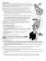
Evaporative Cooling
Evaporative cooling uses the principle of evaporation to lower the air
temperature. Hot, dry air is passed through wetted filters and is converted to
refreshingly cooled air. Champion/Essick coolers make the best use of the
evaporative process by controlling the flow of water, spreading the water evenly
over the filters, and keeping a steady stream of cooled air entering your home.
It is exhausted out open windows or doors, carrying heat, smoke and odors
along with it. Champion/Essick evaporative coolers are 80% less costly to
operate than refrigerated air conditioners.
P/N 71088
REV 1/06

2
SAFETY GUIDE LINES & CAUTIONS
When Installing When Operating When Servicing
Make sure that unit is installed on a sound
structure that will support the full operating
weight of the cooler. See page 4.
Make sure that circuit cooler is plugged into is
equipped with a (slow blow) breaker large
enough to support the full amperage of the
cooler.
Always Unplug the cooler before attempting
service of any kind.
Before attempting to hang the cooler in the
window, remove the louvers to reduce weight.
To reduce the risk of fire or electrical shock, DO
NOT use this fan with any Solid-state speed
control device.
Be sure to disconnect unit from power
source before servicing. If not, it can be
turned on from inside the house and start
unexpectedly.
Do NOT connect power to cooler before
installation is complete.
This cooler is equipped with an
UUUUautomaticUUUU
thermally protected motor. If it shuts off on its
own for any reason,
UUUUit can restart without
warningUUUU.
If the motor shuts off because of thermal
overload, check into the problem
immediately. If allowed to continue,
permanent damage will occur.
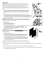
MOUNTING
To install this cooler, the following tools are required:
• Adjustable wrenches
• Screwdrivers
• Electric drill
• 3/16” drill bit
• Level
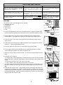
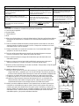
1. Loosen the Adjustment Screw in the Stand-Off Bracket. Remove the Spacer-Rod
from the installation package and insert them into the Stand-Off brackets as shown.
2. Cut the Side Sealer Channels so that two of them will span the window when
butted together. Place two of the channels on the bottom duct flange as shown.
3. Place the Cooler in the center of the window with the bottom duct flange resting
against the sill.
4. Pull out the Spacer-Rods so as to allow the Rubber Feet to rest against the side of
the house. Tighten the Adjustment Screws.
5. Lower the window to rest on top of the duct behind the top duct flange.
6. Fasten a stop above the inside window sash to prevent the window from being
raised. Raising the window may cause the cooler to fall.
7. Adjust the Spacer-Rods to level the cooler. This will ensure proper water flow to the
pads.
8. Install the Chain Supports.
a. Drill pilot holes in the window frame, 3 feet above the top of the duct and the width
of the cooler apart. Install the Screw-Hooks in these pilot holes to the full depth of the
thread.
b. Hook one end of each Chain over each Screw-Hook.
c. Place S-Hooks in the in the holes at the top-rear of the cooler.
d. Place the opposite end of the S-Hooks in the free end of each Chain. Make sure
the chains are taut, but not so tight they pull the bottom of the cooler away from the
wall.
9. Install the Side Sealer Panels. These panels are the correct height, but need to be
trimmed to fit the width of your window. Trim the panels so that they reach from the
window frame to the side of the duct. Slide the panels in the channels you placed on
the bottom duct flange. Install the remaining Side-Sealer Channels over the top duct
flange and the Side-Sealer Panels.

3
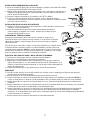
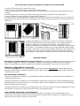
INSTALL OVERFLOW AND DRAIN
1. Slide the Rubber Washer over the Drain Bushing and push through the hole in the
bottom of the cooler from the top side.
2. Secure the Drain Bushing from beneath the pan with the Lock Nut. Make sure the
Rubber Washer does not twist while tightening, which could cause it to leak.
UUUUDO NOT
OVERTIGHTEN.UUUU
3. Thread the Overflow Tube into the Drain Bushing and HAND TIGHTEN.
4. If leakage occurs after Reservoir is full, retighten the Overflow Pipe until leaking stops.
A small amount of silicone caulk may be used if necessary.
FLOAT VALVE INSTALLATION
1. Place the threaded portion of the Float Valve through the hole provided in the Corner
Post from the inside.
2. Slip the Fiber Washer over the threaded portion outside the corner post and secure with
the Nut. Be sure the Float does not turn while you are tightening the Nut.
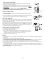
WATER LINE CONNECTION
Find the closest outside water faucet, and install a Water Connection Kit (not included with
cooler) as shown. If an exterior faucet is not available, locate the closest cold water pipe
and install a saddle valve assembly.
Route tubing to cooler. Place Compression Nut and Ferrule over end of tubing. Insert the
tubing into float valve and tighten Compression Nut to secure. NOTE: Over tightening the
compression fitting will cause that fitting to leak. It is best to secure the connections, turn
on the water, and then snug the fitting until leaking stops.
ADJUSTING WATER LEVEL AND FLOAT VALVE
• To adjust water level, bend the float valve rod.
• Check all water connections for leaks.
• Make sure the Float Valve cuts off completely when the desired water level has been
reached (½” to ¾” below top of Overflow Tube). If the float does not stop the water
completely, the water level will rise and run out the Overflow Tube.
• Double check the Overflow Tube for leaks.
START UP
1. Plug in the electrical cord to a standard grounded receptacle. Be sure the Circuit Breaker protecting the receptacle is of
sufficient size.
2. Open windows in rooms where you want cooling to be directed.
3. Turn the cooler to the High Fan position. Observe the amount of air being delivered. Note: on cool nights (or days) or
when the humidity level is high, the fan positions may be used for ventilation purposes.
4. Turn the cooler to the Low Fan position. This should significantly reduce the amount of air being delivered.
5. Turn the cooler to the Pump Only position. The pump should run and not the fan. Check to see that water is flowing
from all three Water Trays.
6. Turn the cooler to the High Cool position. Check to see that all three Pads are wetting evenly with no dry patches. The
Pads may take up to 20 minutes to wet fully. If the Pads have dry patches, you can adjust the level of each Water Tray
by screws on each end.
7. Adjust window openings to achieve desired cooling level.
Reservoir
Ferrule
Faucet

4
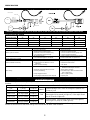
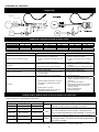
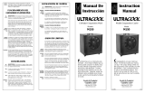
WIRING DIAGRAM
CAUTION: Always unplug cooler before opening or attempting service of any kind.
WARNING: To reduce the risk of fire or electric shock, do not use this fan with any solid-state speed control device.
COOLER SPECIFICATIONS
Model Height Width Depth Amps Shipping Weight Operating Weight
(R)WC50/(R)N50W 35” 34” 34” 8.4 165 249
(R)WC46/(R)N46W 35” 34” 34” 7.4 165 249
(R)WC44 35” 34” 28” 7.4 147 217
(R)WC35/(R)N35W 31” 32” 21” 7.4 135 184
TROUBLE SHOOTING
Problem Cause Remedy
Motor cycles on and off
• Excessive belt tension
• Blower shaft not spinning freely
• Extension cord (if one used) too long
• Circuit breaker not large enough
• Adjust belt tension
• Lubricate or replace bearings
• Choose a shorter or heavier gauge cord
• Consult a licensed electrician
Fails to start
• No electrical power
• Circuit breaker tripped or fuse blown
• Check all electrical connections and cords
• Reset circuit breaker or replace fuse
Water draining from overflow
• Float improperly adjusted • Adjust float
Blower vibrates excessively
• Belt or pulley loose
• Blower wheel out of balance or out of
alignment
• Debris in blower housing
• Adjust belt or tighten pulley
• Replace the blower wheel
• Clear debris
Not cooling
• Blocked water lines
• Windows opened too little or too much.
• Uneven pad wetting
• Pump clogged or failed
• Pads plugged with dirt and water deposits
• Check incoming water line, float and water
distributor for blockages and clear.
• Adjust window openings
• Level water trays, check for blocked water
slots in water trays
• Clean or replace pump
• Replace pads
This cooler is equipped with an UUUUautomaticUUUU thermally protected motor. If it shuts off on its own for any reason, UUUUit
can restart without warningUUUU.
Your cooler may be controlled by a rotary switch (MANUAL CONTROLS) or by a touch pad/remote control. See below for
functions.
Note: pressing the ON/OFF button while the unit is running will turn off power to the entire unit. Pressing the button again
will turn the unit back on at the same setting, which the unit was at when it was turned off.
Switch Operation Remote Control Operation
OFF Fan off Pump off
PUMP ONLY Fan off Pump on
ON/OFF
Controls power to unit. Does not change fan speed or turn
Pump on or off.
HIGH COOL Fan high speed Pump on
LOW COOL Fan low speed Pump on
FAN
Controls Fan speed. Press once for high speed (HI light on).
Press again for low speed (LO light on). Press again to turn
fan off (HI and LO lights off).
HIGH VENT Fan high speed Pump off
LOW VENT Fan low speed Pump off
PUMP
Controls Pump. Press once for pump on (PUMP light on).
Press again for pump off (PUMP light off).
Black - Hi
Red - Low
White - Common
Green - Ground
Motor
Pump
Switch
Wiring Harness
Motor Cord
Manual Control

5
MAINTENANCE
NOTE: The fan motor is thermally protected with an automatic reset and will
automatically stop if overloaded. After the motor cools, it will restart automatically.
If this occurs, check into the problem before permanent damage occurs.
Once a month during cooling season, inspect your cooler for leaks, proper belt
tension and alignment, blocked water lines and excessive residue build-up on the
pads.
• To adjust belt tension, loosen the 4 Adjustment Bolts (2 each side) on the Motor
Mount. Adjust belt tension so that 3 pounds of pressure (lightly push with one
finger) will cause the belt to deflect ¾”, as shown. Retighten the Adjustment
Bolts.
• Use SAE 20W or SAE 30W non-detergent oil to lube the bearings. Place 2 to 3
drops in the bearing oil cups at the beginning of the season and no more than once a
season during cooling season. If the motor has oil holes (usually plugged with yellow
caps that read “OIL” at either end of the motor) oil the motor also, following the same
procedure as for bearings.
NOTE: Excessive oil in the bearings may leak out and be drawn into the air stream.
Excessive oil in the motor may leak onto the motor windings and damage the motor.
Do NOT oil bearings prior to initial start-up.
• To replace pads
1. Remove louver from cooler.
2. Unhook pad holders and remove.
3. Remove and discard old pad.
4. Clean water deposits from the louver. If the paint is chipped or rust spots occur, sand
the spots and paint louver with a rust resistant exterior paint.
5. Place new filter in louver and tuck in to prevent hot air from bypassing.
6. Replace pad holders and hook into place.
7. Replace louver in cooler.
NOTE: It is best to replace filter pads
UUUUat the end of the seasonUUUU. Old filter pads
soak up lime and salts that can rust louvers and the cabinet during the wet,
rainy winter months.
• At the end of the season
1. Remove the Overflow Tube and let the water drain from the reservoir.
(The bushing is threaded to accept a standard garden hose. If desired, a
garden hose may be used to route water away from your house.)
2. Rinse dirt and debris from the pan and clean any water deposits that may
have collected in the reservoir or on any interior surface of the cooler.
3. If the paint is chipped or rust spots occur sand the spots and paint with a
rust resistant exterior paint.
4. Replace the Overflow Tube when you start the cooler for the next season.
NOTE: Do not get water on the Fan Motor or Pump Motor. This will cause damage.
• If freezing weather occurs in your area, it is best to shut off the water supply at the source and drain the supply line to
the cooler.
• A canvas cooler cover is recommended to prevent rain and weather from damaging your cooler.
• To prevent the Shaft from rusting, coat with a wax based lubricant. Allow Lubricant to dry completely and all fumes to
disperse before turning on the cooler.
3/4"

6
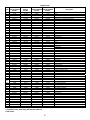
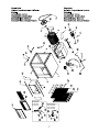
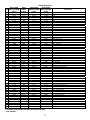
Repair Parts
Item
WC35, N35W
RWC35, RN35W
Part No.
WC44
RWC44
Part No.
WC46, N46W
RWC46, RN46W
Part No.
WC50, N50W
RWC50, RN50W
Part No.
Description
1 70735 70738 71090 71090 Top
2 70737 70740 70740 70740 Front
3 70736 70739 70759 70759 Bottom
4 504242 504245 504245 504245 Corner Post – Plain
4* 504243 504246 504246 504246 Corner Post – W/Float Valve Hole
5 70808 70808 70808 70808 Duct
6 70806 70744 70744 70744 Blower Housing
7 30318 30322 30322 30322 Blower Wheel
8 30241 30238-02 30238-02 30238-02 Blower Shaft
9 501244 501241 501241 501241 Fiber Washer
10 524330 524331 524331 524331 Set Collar
11 583000 60PB 60PB 60PB Bearing
12 583009 583091 583091 583091 Blower Pulley
13 582093 582030 582030 582030 Belt
14 504302 504289 504296 504296 Blower Brace
15 515160 512574 512574 512574 Motor Mount
16 595121 595121 595121 595121 Motor Cord
17 524162 524162 524162 524162 Motor Saddle Clamps
18 581188 581188 581188 50310 Motor
19 31085 31085 31085 16579 Motor Pulley
20 *** *** *** *** Water Tube Holder
21 598474 598474 598472 598472 Water Hose
22 512551 512550 512548 512548 Water Distributor
23 71098 70488 70488 70488 Pump Bracket
24 506669 506669 506669 506669 Pump
25 70613 70613 70613 70613 Overflow Kit
26 504253 504254 504256 504256 Pad Retainer (Side)
26 504255 504256 504256 504256 Pad Retainer (Back)
27* 141N 120N 71099 71099 Filter Set
27 516153 516157 503314 503314 Filter (Side)
27* 516155 503314 503314 503314 Filter (Back)
28 504258 504262 504263 504263 Louver (Side)
28* 514260 504263 504263 504263 Louver (Back)
29 504266 504267 504269 504269 Water Tray (Side)
29* 504268 504269 504269 504269 Water Tray (Back)
** 70940 70944 70945 70945 Louver Assembly (Side)
** 70941 70945 70945 70945 Louver Assembly (Back)
30 70655 70655 70655 70655 Wiring Harness (manual units only)
31 524299 524299 524299 524299 Switch (manual units only)
32 70664 70664 70664 70664 Knob (manual units only)
33 70798 70798 70798 70798 Switch Bracket (manual units only)
70658 70658 70658 70658 Grill Frame, manual control units
34
71145 71145 71145 71145 Grill Frame, remote control units
35 70741 70741 70741 70741 Sub-Vent Assembly
36 70925 70924 70924 70924 Bearing Support
37 70667 70667 70667 70667 Grill Cover (Sold separately)
38 70656 70656 70656 70656 Side Sealer Channel
39 70618 70618 70618 70618 Side Sealer
40 524344 524344 524344 524344 Rubber Foot
41 504341 504341 504341 504341 Spacer Rod
42 504337 504337 504337 504337 Stand-Off Bracket
43 502389 502389 502389 502389 Float
44 70801 70801 70801 70801 Pump Basket
* 70804 70804 70804 70804 Duct Mount Strip
45 71113 71113 71113 71113 Dress Ring (remote units only)
46 71114 71114 71114 71114 Electronic Control Assembly (remote units only)
47 71115 71115 71115 71115 Lock Plate (remote units only)
48 71116 71116 71116 71116 Remote Control (remote units only)
* Item not shown
** Contains louver, water tray, pad and pad retainers
*** Not used

7
23
Models/Modelos:
RWC35/RN35W,
RWC46/RN46W,
RWC50/RN50W
Models/Modelos:
WC35/N35W,
WC46/N46W,
WC50/N50W

8
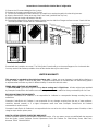
Instructions to Convert Unit to Vertical Duct Configuration
1. Remove the 13 screws holding the Duct in place.
2. Replace the 4 screws removed from the Top Pan.
3. Turn the Duct 90 degrees counter-clockwise. Be careful not to unplug the switch from the wiring harness.
4. Align the Duct with the 3 holes at the top of the Front Panel (just below the Top Pan).
5. Insert 3 screws at the top and bottom of the duct.
6. Place the Duct Mount Strips (found in bottom of cooler) over the side Duct Flanges and insert screws 3 each side into
the holes provided (3 screws will be in installation kit).
Proceed with the installation as normal. The Side Sealer Channels will go on the same flanges as for a horizontal duct.
You may use the Side Sealers provided to close off the window above your cooler’s duct.
LIMITED WARRANTY
This warranty is extended to the original purchaser only. It does not cover damages incurred during shipping or
through accident, neglect, or abuse by the owner. Champion Cooler/Essick Air Products does not authorize any person
or representative to assume any other or different liability in connection with this cooler.
TERMS AND CONDITIONS OF WARRANTY
The BOTTOM PAN is guaranteed against leakage due to rusting out
for Eight Years. All other original parts provided
by Champion Cooler/Essick Air Products are warranted against defects in material or factory workmanship for One Year.
EXCLUSIONS FROM THE WARRANTY
Champion Cooler/Essick Air Products is not responsible for incidental or consequential damage resulting from any
malfunction.
Champion Cooler/Essick Air Products is not responsible for any damage occurring from the use of water softeners,
chemicals, descale material, or if a higher horsepower motor than what Champion Cooler/Essick Air Products
recommends is used in the unit.
Champion Cooler/Essick Air Products is not responsible for the cost of service calls to diagnose cause of trouble, or labor
charge to repair and/or replace parts.
HOW TO OBTAIN SERVICE UNDER THIS WARRANTY
Contact the Dealer where you purchased the evaporative cooler. If for any reason you are not satisfied with the response
from the Dealer, contact Customer Service Department: Essick Air Products Inc. 5800 Murray Street, Little Rock,
Arkansas 72209. 1-800-643-8341.

1
Manual del
Propietario
Modelos #
WC35, RWC35
N35W, RN35W
WC44, RWC44
WC46, RWC46
N46W, RN46W
WC50, RWC50
N50W, RN50W
Lea Y Gaurde Este
Manual de Instrucción!
Enfriador Evaporativo
De Ventana
Enfriamiento por evaporación
El enfriamiento por evaporación usa el principio de la evaporación para bajar la
temperatura del aire. El aire seco y caliente pasa por filtros mojados y es
transformado en aire frío y fresco. Los enfriadores Champion/Essick utilizan en
forma óptima el proceso evaporativo controlando el flujo de agua, esparciendo el
agua en forma pareja sobre los filtros y manteniendo un flujo constante de aire
frío en la casa. El enfriador se agota a través de ventanas o de puertas abiertas,
extrayendo el calor, el humo y los olores. Los enfriadores evaporativos de
Champion/ Essick son 80% más económicos de operar que los acondicionadores
de aire por refrigeración.
P/N 71088
REV 01/06

2
Indicaciones y precauciones de seguridad
Instalación Operación Servicio
Asegure que la unidad está instalada sobre una
estructura firme que soporte el peso total
operativo del enfriador.
Vea página 4.
Asegure que el circuito al que el enfriador está
enchufado (soplador lento) tenga instalado un
disyuntor de suficiente capacidad para soportar
el amperaje total del enfriador.
Siempre desenchufe el enfriador antes de
iniciar cualquier clase de servicio de
mantenimiento.
Antes de intentar instalar el enfriador en la
ventana, retire las parrillas para eliminar el peso
innecesario.
Para reducir el riesgo de incendio o de choque
eléctrico, NO USE este soplador junto con
ningún artefacto de control de velocidad de
estado sólido
Asegure de desconectar la unidad de la
fuente de electricidad, antes de iniciar el
servicio. De no hacerlo, la unidad puede ser
encendida desde otro lugar y comenzar a
funcionar sin previo aviso.
No enchufe el enfriador en una fuente de
electricidad antes de haber terminado la
instalación .
Esta unidad está equipada con un motor de
protección termal automático
. Si se apaga por si
sólo y por cualquier motivo, también puede
volver a encenderse sin previo aviso.
Si el motor se apaga por recalentamiento,
revise el problema de inmediato. Si se deja
funcionando, puede ocurrir un daño
permanente.
MONTAJE
Para instalar el enfriador se necesitan las siguientes herramientas:
• Llave de tuerca regulable
• Desatornillador
• Taladro eléctrico
• Nivel
1. Afloje el tornillo de ajuste en la ménsula distanciadora. Retire las varillas distanciadoras
del paquete de instalación e insértelos en las ménsulas distanciadoras tal como se
muestra.
2. Corte las canaletas selladoras laterales para que ambas cubran todo el ancho de la
ventana cuando se instalan una junto a la otra. Coloque dos canaletas en el canal
embridado inferior como se muestra.
3. Coloque el enfriador en el centro de la ventana con el canal embridado inferior
apoyado en la solera de la ventana.
4. Estire las varillas espaciadoras para permitir que las patas de goma se apoyen
contra el costado de la casa. Apriete los tornillos de ajuste.
5. Baje la ventana hasta que se apoye dentro del ducto que está detrás del canal
embridado superior.
6. Asegure un tope en la parte interior del bastidor de la ventana para evitar que la
ventana sea abierta. Si se abre la ventana, el enfriador puede caerse.
7. Ajuste las varillas espaciadoras para nivelar el enfriador. Esto permite un flujo de agua
adecuado hacia las almohadillas.
8. Instale las cadenas de soporte.
a. Perfore orificios pilotos en el marco de la ventana, a 3 pies por encima de la parte
superior del ducto y separados por el ancho del enfriador. Atornille los ganchos de
tornillo en estos orificios pilotos hasta que la rosca esté introducida completamente.
b. Enganche un eslabón del extremo de cada cadena en cada gancho de tornillo.
c. Coloque los gancho en S en los orificios en la parte superior trasera del enfriador
d. Enganche la punta opuesta al extremo de los ganchos en S en el eslabón del
extremo libre de cada cadena. Asegure que las cadenas están tensas pero no
excesivamente tirantes como para que separen el enfiador de la pared.
9. Instale los paneles selladores laterales. Estos paneles tienen la altura correcta pero
necesitan ser recortados para que se ajusten al ancho de la ventana. Recorte los
paneles para que estos puedan llenar el espacio entre el enfriador y el marco de la
ventana. Deslice los paneles por las canaletas selladoras que instaló, dentro del canal
embridado inferior. Instale las demás canaletas selladoras por encima del canal
embridado superior y los paneles selladores laterales.

3
INSTALACIÓN DE REBOSADURA Y DESAGÜE
1. Deslice la arandela de goma sobre el buje del deasgüe y empuje a través del orificio desde
la parte superior del enfriador, hacia la parte inferior.
2. Asegure el buje de desagüe por debajo de la bandeja con la contra-tuerca. Asegure que la
arandela no se tuerza mientras se la está apretando, pues esto puede causar filtración.
NO LA APRIETE DEMASIADO.
3. Enrosque el tubo de rebosamiento en la boquilla y APRIETE A MANO.
4. Si ocurre una filtración después de llenar el tanque , vuelva a apretar el tubo de
rebosamiento hasta detener la filtración. Puede usarse una pequeña cantidad de calafate
con silicona de ser necesario.
INSTALACIÓN DE LA VÁLVULA DE FLOTACIÓN
1. Introduzca la parte enroscada de la válvula flotadora a través del orificio interior que se
encuentra en el poste esquinero.
2. Deslice la arandela de fibra por sobre la parte enroscada que sobresale el
poste esquinero y asegúrela con la tuerca. Asegure que la válvula no gire
mientras está ajustando la tuerca.
CONEXIÓN DEL TUBO PARA AGUA
Encuentre el grifo de agua exterior más cercano e instale el Juego para la
Conexión de Agua (no incluída) tal como se muestra. Si no encuentra un grifo de
agua exterior, ubique la cañeria de agua fria más cercana e instale un juego de
válvula de asiento.
Dirija el tubo hacia el enfriador. Coloque la tuerca de compresión y el casquillo sobre
el extremo del tubo. Introduzca el tubo en la válvula flotadora y apriete la tuerca de
compresión para asegurarla. NOTA: el apretar demasiado un conector de compresión
puede causar una filtración. Es mejor primero asegurar las conexiones y abrir el agua
para sólo después ajustar la conexion hasta detener la filtración.
AJUSTE DE DEL NIVEL DE AGUA Y DE LA VÁLVULA FLOTADORA
• Para ajustar el nivel de agua, doble la varilla de la válvula flotadora.
• Busque por si hay filtraciones en alguna de las conexiones.
• Asegure que la válvula flotadora corte completamente el flujo de agua cuando se
llega al nivel deseado (½” a ¾” por debajo del tope del tubo de rebosamiento). Si el
flotador no corta el flujo de agua totalmente, el nivel de agua subirá y desaguará por
el tubo de rebosamiento.
• Verifique nuevamente que no haya filtraciones por el tubo de rebosamiento
ARRANQUE
1. Enchufe el cordón eléctrico a un enchufe estándar con conexión a tierra. Asegure que el disyuntor que proteje el
receptáculo tenga suficiente capacidad.
2. Abra las ventanas en los cuartos adonde usted quiera que se dirija el aire frío.
3. Coloque el enfriador en la posición de Soplador Alto (Fan High). Observe la cantidad de aire producida. NOTA: en
noches (o días) frescos o cuando el nivel de humedad es alto, el enfriador puede ser usado sólo como ventilador.
4. Coloque el enfriador en la posición de Soplador Bajo (Fan Low). Esto reduce significativamente la cantidad de aire
producido.
5. Coloque el enfriador en la posición de Sólo Bomba (Pump Only). Sólamente debe funcionar la bomba y no el soplador.
Verifique que el agua está circulando desde las tres bandejas de agua.
6. Coloque el enfriador en la posición Frío Alto (High Cool). Verifique que las tres almohadillas se están impregnando
uniformemente sin dejar áreas secas. Puede tomar hasta 20 minutos para que las almohadillas se impregnen
totalmente. Si las almohadillas tienen áreas secas, usted puede ajustar el nivel de cada bandeja de agua girando los
tornillos ubicados en los extremos.
7. Ajuste la abertura de las ventanas para obtener el enfriamiento deseado.
Tanque
Casquillo
Grifo

4
DIAGRAMA DEL CABLEADO
ATENCIÓN: siempre desenchufe el enfriador antes de abrirlo o de tratar de darle servicio o mantenimiento de
cualquier tipo.
PRECAUCIÓN: para reducir el riesgo de incendio o de choque eléctrico, no use este soplador con ningún tipo de
artefacto de control de velocidad de estado-sólido.
ESPECIFICACIONES DEL ENFRIADOR
Modelo Alto Ancho Profundidad Amperes Peso de embalaje Peso operativo
(R)WC50/(R)N50W 35” 34” 34” 8.4 165 249
(R)WC46/(R)N46W 35” 34” 34” 7.4 165 249
(R)WC44 35” 34” 28” 7.4 147 217
(R)WC35/(R)N35W 31” 32” 21” 7.4 135 184
SOLUCIÓN POR MAL FUNCIONAMIENTO
Problema Causa Solución
Motor en ciclos de enciende y apaga
• Correa demasiado tensa.
• Eje del soplador no gira libremente.
• Cordón de extensión demasiado largo (si se
usa).
• Disyuntor de capacidad insuficiente.
• Ajustar la tensión de la correa
• Lubricar o reemplazar cojinetes.
• Escoger un cordón más corto o de mayor
calibre.
• Consultar con un electricista licenciado
No arranca
• No hay electricidad.
• Disyuntor disparado o fusible quemado.
• Revisar todas las conexiones eléctricas y
cordones.
• Reposicionar disyuntor o reemplazar fusible.
Agua desagota por rebalsamiento
• Flotador mal ajustado. • Ajustar flotador.
Enfriador vibra demasiado
• Correa o polea sueltas.
• Rueda del soplador desbalanceada o fuera
de alineamiento.
• Desechos dentro de la caja del soplador.
• Ajustar correa o apretar polea.
• Reemplazar la rueda del soplador.
• Limpiar los desechos.
No enfría
• Cañería de agua taponada.
• Ventanas abiertas demasiado o muy poco.
• Almohadillas no impregnadas de forma
uniforme.
• Bomba tapada o con fallas.
• Almohadillas obturadas por suciedad o
depositos calcáreos del agua.
• Revisar la cañería de entrada de agua,
flotador y distribuidor de agua por posible
bloqueos.
• Ajustar abertura de ventanas.
• Nivelar bandejas de agua, buscar posible
agua taponada en las ranuras de las
bandejas de agua.
• Limpiar o cambiar bomba.
• Cambiar almohadillas.
Este enfriador está equipado con un motor de protección termal automático. Si se apaga por si sólo por
cualquier motivo, también puede volver a encenderse sin previo aviso.
Su más fresco puede ser controlado por un interruptor (CONTROLES MANUALES) o por una almohadilla del toque/el
mando a distancia. Vea abajo para funciones.
Nota: apretando el EN/LEJOS botón mientras la unidad corre girará lejos poder a la unidad entera. Apretar el botón otra
vez girará la espalda de la unidad en en la misma colocación, que la unidad estaba en cuando se giró lejos.
Switch Operation Remote Control Operation
OFF Ventilador apagar Pompa apagar
PUMP ONLY Ventilador apagar Pompa prender
ON/OFF
Controla corriente se unidad. No cambia velocidad del
ventilador cuando bomba es apagada o prendida.
HIGH COOL Alto Ventilador Pompa prender
LOW COOL Bajo Ventilador Pompa prender
FAN
Controla velocidad del ventilador. Presione una vez mas
para alta velocidad (luz HI se prende). Presione otra vez
mas para baja velocidad (luz LOW se prende). Presione otra
vez mas para apagar ventilador (luz HI y LOW se apaga).
HIGH VENT Alto Ventilador Pompa apagar
LOW VENT Bajo Ventilador Pompa apagar
PUMP
Control de bomba. Presionar una vez para prender bomba
(luz PUMP prende). Presionar otra vez para apagar bomba
(luz PUMP se apaga).
Motor
Mando Manual
Verde - Tierra
Blanco - Comun
Rojo - Baja
Negro - Alta
Bomba
Montaje de Mando
Cordon del Motor
Cambia

5
MANTENIMIENTO
NOTA: el motor de este soplador está térmicamente protegido con un reposicionador
automático y se detendra automáticamente en caso de una sobrecarga. Después de que
el motor se enfrie, arrancará nuevamente de forma automática. Si sucede esto, corrija el
problema antes de que ocurra un daño permanente.
En forma mensual durante la estación fría, inspeccione su enfriador para buscar
filtraciones, verifivar tensión y alineamiento correcto de la correa, cañerías de agua
taponadas y acumulación excesiva de residuos en las almohadillas.
• Para ajustar la tensión de la correa, suelte los 4 pernos de ajuste ( dos a cada lado)
ubicados en el montaje del motor. Ajuste la tensión del motor para que 3 libras de
presión (empuje levemente con un dedo) causen que la correa se desvíe ¾” como se
muestra. Vuelva a apretar los pernos de ajuste.
• Use aceite SAE-20 o SAE-30 sin detergente para lubricar los cojinetes. Coloque 2 a 3
gotas en cada taza lubricadora del cojinete al comenzar la temporada y no más
de una vez durante la temporada fría. Si el motor tiene orificios para lubricación
(generalmente tapados con tapones amarillos que tienen escritos la palabra
ACEITE (OIL) en cualquier costado del motor, también lubrique el motor,
siguiendo el mismo procedimiento que en el caso de los cojinetes.
NOTA: una lubricación excesiva en los cojinetes puede rebasar y ser aspirada por la
corriente de aire. Una lubricación excesiva en el motor puede rebasar hacia el
bobinado del motor y dañar el motor.
• Para reemplazar las almohadillas.
1. Retire las parrillas del enfriador
2. Desenganche los retenes de las almohadillas y retírelos
3. Retire y bote las almohadillas viejas
4. Limpie los depósitos de agua de las parrillas. Si la pintura está picada u oxidada,
lije las oxidaciones y vuelva a pintar con una pintura para exterior resistente a la
corrosión.
5. Coloque el filtro nuevo en la parrilla y ajústelo bien para evitar que deje
pasar aire caliente
6. Vuelva a instalar correctamente la parrillas de las almohadillas y sus
retenes
7. Vuelva a colocar las parrillas en el enfriador.
NOTA: es recomendable reemplazar las almohadillas filtrantes al final de la
temporada. Las almohadillas viejas chupan caliza y sales minerales que
pueden corroer las parrillas y la caja del enfriador durante los meses
húmedos y lluviosos del invierno.
• Al final de la temporada
1. Retire el tubo de rebosamiento y deje desagotar el agua del tanque (el buje tiene una rosca para permitir la conexión
de una manguera de riego común, si se desea usar una manguera para desagotar directamente lejos de la casa).
2. Enjuague la suciedad y los desechos de la bandeja y limpie cualquier depósito de agua que pueda haberse juntado en
el tanque o en cualquier superficie interior del enfriador.
3. Si la pintura está picada u oxidada, lije las oxidaciones y vuelva a pintar con una pintura para exterior resistente a la
corrosión.
4. Vuelva a instalar el tubo de rebosamiento al inicio de la próxima temporada y antes de arrancar el enfriador.
NOTA: No moje el motor del soplador ni el motor de la bomba. Esto puede causar daños.
• Si sucede una helada en su área, es recomendable cortar el agua en el grifo de suministro de agua y desagotar el
tubo de alimentación que va hacia el enfriador.
• Se recomienda colocar una cubierta lona protectora sobre el enfriador para prevenir daños causados por la lluvia y el
mal tiempo.
• Para prevenir la corrosión del eje, cúbralo con un lubricante a base de cera. Deje que el lubricante se seque
completamente y que todos los vapores se hayan dispersado antes de arrancar el enfriador nuevamente.
3/4"

6
Lista de Repuestos
Item
WC35, N35W
RWC35, RN35W
Parte #
WC44
RWC44
Parte #
WC46, N46W
RWC46, RN46W
Parte #
WC50, N50W
RWC50, RN50W
Parte #
Descripción
1 70735 70738 71090 71090 Tapa
2 70737 70740 70740 70740 Frente
3 70736 70739 70759 70759 Base
4 504242 504245 504245 504245 Poste esquinero – simple
4* 504243 504246 504246 504246 Poste esquinero con orificio para válvula flotadora
5 70808 70808 70808 70808 Canal
6 70806 70744 70744 70744 Caja para el soplador
7 30318 30322 30322 30322 Rueda del soplador
8 30241 30238-02 30238-02 30238-02 Eje del soplador
9 501244 501241 501241 501241 Arandela de fibra
10 524330 524331 524331 524331 Juego de collar
11 583000 60PB 60PB 60PB Cojinete
12 583009 583091 583091 583091 Polea del soplador
13 582093 582030 582030 582030 Correa
14 504302 504289 504296 504296 Abrazadera para soplador
15 515160 512574 512574 512574 Montaje para motor
16 595121 595121 595121 595121 Cable para motor
17 524162 524162 524162 524162 Grapas para asiento de motor
18 581188 581188 581188 50310 Motor
19 31085 31085 31085 16579 Polea de motor
20 *** *** *** *** Sujetador de tubo de agua
21 598474 598474 598472 598472 Manguera para agua
22 512551 512550 512548 512548 Distribuidor de agua
23 71098 70488 70488 70488 Ménsula para bomba
24 506669 506669 506669 506669 Bomba
25 70613 70613 70613 70613 Juego para desagüe
26 504253 504254 504256 504256 Retén de filtro (lateral)
26 504255 504256 504256 504256 Retén de filtro (trasero)
27* 141N 120N 71099 71099 Juego de filtros
27 516153 516157 503314 503314 Filtro (lateral)
27* 516155 503314 503314 503314 Filtro (trasero)
28 504258 504262 504263 504263 Rejilla (lateral)
28* 514260 504263 504263 504263 Rejilla (trasera)
29 504266 504267 504269 504269 Bandeja de agua (lateral)
29* 504268 504269 504269 504269 Bandeja de agua (trasera)
** 70940 70944 70945 70945 Assemblea de rejilla (lateral)
** 70941 70945 70945 70945 Assemblea de rejilla (trasera)
30 70655 70655 70655 70655 Arnés de cableado (unidades manuales solo)
31 524299 524299 524299 524299 Interruptor (unidades manuales solo)
32 70664 70664 70664 70664 Perilla (unidades manuales solo)
33 70798 70798 70798 70798 Ménsula para interruptor (unidades manuales solo)
70658 70658 70658 70658 Marco de rejilla (unidades manuales solo)
34
71145 71145 71145 71145 Marco de rejilla (unidades remotas sólo)
35 70741 70741 70741 70741 Conjunto de rejilla de ventilación
36 70925 70924 70924 70924 Retén para tapa de rejilla
37 70667 70667 70667 70667 Tapa de rejilla
38 70656 70656 70656 70656 Canaleta para panel sellador
39 70618 70618 70618 70618 Panel sellador lateral
40 524344 524344 524344 524344 Pata de goma
41 504341 504341 504341 504341 Varilla distanciadora
42 504337 504337 504337 504337 Ménsula distanciadora
43 502389 502389 502389 502389 Flotador
44 70801 70801 70801 70801 Malla parra la bomba
* 70804 70804 70804 70804 Strip para canal
45 71113 71113 71113 71113 Dress Ring (unidades remotas sólo)
46 71114 71114 71114 71114 Electronic Control Assembly (unidades remotas sólo)
47 71115 71115 71115 71115 Lock Plate (unidades remotas sólo)
48 71116 71116 71116 71116 Remote Control (unidades remotas sólo)
* Item no mostrado
** Contiene rejilla, bandeja de agua, filtro y Retén de filtro
*** No utilizado

7
23
Models/Modelos:
RWC35/RN35W,
RWC46/RN46W,
RWC50/RN50W
Models/Modelos:
WC35/N35W,
WC46/N46W,
WC50/N50W

8
Instrucciones para convertir la unidad para el montaje en una ventana batiente.
1. Retire los 13 tornillos que fijan el ducto en su lugar.
2. Vuelva a colocar los 4 tornillos que se retiraron de la cubeta superior.
3. Vire el ducto 90 grados en el sentido contrario al reloj. Tenga cuidado de no desenchufar el interruptor del arnés de
cableado.
4. Alinie el ducto con los 3 orificios en la parte superior del panel frontal (justo debajo de la cubeta superior).
5. Inserte 3 tornillos en la parte superior y en la parte inferior del ducto.
6. Coloque los flejes para montaje del ducto (que se encuentran en la parte inferior del enfriador), sobre las cantoneras
laterales del ducto e inserte los tornillos, 3 a cada lado, en los orificios provistos (encontrará 3 tornillos en el juego para
instalación).
Continue normalmente con la instalación, tomando en cuenta que su ventana se
desplaza horizontalmente en lugar de verticalmente. Las canaletas selladoras
laterales se montarán en los mismos flejes normales. Usted puede usar las
selladoras laterales que se suministran, para sellar su ventana por encima del ducto
del enfriador. Si las selladoras laterales no son lo suficientemente grandes, puede
contactar a nuestra oficina para comprar selladoras adicionales. No trate de instalar
el enfriador con la base del ducto colocada más alta que la solera de la ventana.
Esto resultará en una instalación inestable y creará una situación de mucho peligro.
GARANTIA LIMITADA
Esta garantía se extiende sólamente al comprador original. No cubre daños ocurridos durante el transporte por causa
de accidentes, negligencia o abuso por el propietario. Champion Cooler/Essick Air Products no autoriza a ninguna
persona o representante para asumir cualquier otra o diferente responsabilidad civil en relación a este enfriador.
TÉRMINOS Y CONDICIONES DE LA GARANTÍA
Garantía por Ocho Años sobre la cubeta de agua por filtraciones causadas por corrosión
. Todas las demás piezas
originales suministradas por Champion Cooler/Essick Air Products están garantizadas contra defectos del material o de
mano de obra por un año.
EXCLUSIÓNES DE LA GARANTÍA
Champion Cooler/Essick Air Products no es responsable por daños incidentales o consecuentes como resultado de un
funciónamiento defectuoso.
Champion Cooler/Essick Air Products no es responsable por ningún daño causado por el uso de ablandadores de agua,
productos químicos, material anticorrosivo, o si se utiliza un motor con más caballos de fuerza de los recomendados por
Essick Air Products para esta unidad.
Champion Cooler/Essick Air Products no es responsable por el costo de las visitas de servicio para diagnosticar la causa
del problema, o los costos por la mano de obra para reparar y/o reemplazar piezas.
COMO OBTENER SERVICIO BAJO ESTA GARANTÍA
Contactar al concesiónario donde compró el enfriador evaporativo. Si por alguna razón no está satisfecho con la
respuesta del concesiónario, contactar el Servicio de Atención al Cliente; Essick Air Products Inc.; 5800 Murray Street,
Little Rock, Arkansas 72209. Teléfono 1-800-643-8341
-
 1
1
-
 2
2
-
 3
3
-
 4
4
-
 5
5
-
 6
6
-
 7
7
-
 8
8
-
 9
9
-
 10
10
-
 11
11
-
 12
12
-
 13
13
-
 14
14
-
 15
15
-
 16
16


en otros idiomas
- English: Essick RWC46 User manual
Artículos relacionados


Otros documentos
-
 Essick Air M150 Manual de usuario
-
 Brisa BW4502MX El manual del propietario
-
Aerocool BW5502 Manual de usuario
-
 Port-A-Cool PACCYC06 Guía de instalación
-
-
 PMI CTV1 Manual de usuario
-
Champion WC50 Manual de usuario
-
Champion Cooler RWC35 Manual de usuario
-
Belle Foret BFNTLTS01TB Guía de instalación


