
Congratulations: You have purchased a product of superior
performance and design, which will give the best service when
properly operated and maintained. This cooler is intended to be
used as a convenient roll-around spot cooler.
This guide was designed to provide you with the information
needed to prepare the unit for roll-around spot-cooling. It also
contains information on how to safely operate, inspect, maintain
and troubleshoot your Shop Blaster evaporative air cooler.
The rst section contains instructions to prepare your cooler for
roll-around portable service. The second section, Maintenance,
contains operational and maintenance instructions to aid in
keeping your unit in good working order, while Troubleshooting
includes information to help diagnose and repair commonly
encountered problems.
READ AND SAVE THESE IMPORTANT SAFETY
INSTRUCTIONS
Read all instructions carefully before installation
• This cooler must be connected to 120 volt AC, 60 Hz (cycle)
power only. NOTE: Improper voltage will void the pump and/
or motor warranties and may cause serious personal injury or
property damage.
• This cooler is NOT intended for outdoor use.
• Do NOT exceed a maximum weight of 50 pounds per drawer.
• Do NOT exceed a maximum total weight of 600 pounds
including water and toolbox contents.
• Do NOT have more than one drawer open at a time, the unit may
tip.
• When moving this unit ensure the water has been emptied and
all drawers are closed and locked.
• Ensure the brakes on the two rear casters are engaged when the
unit is not being moved.
• This cooler must be plugged into a GFCI protected receptacle,
which has been properly installed in accordance with all local and
national codes. If you are not sure that the receptacle is GFCI
protected, consult with a qualied electrician.
• This cooler is equipped with a power cord having an
equipment grounding conductor and grounding plug. Do NOT
attempt to defeat this safety device by removing the grounding
pin.
• Do NOT step on or rollover power cord with heavy or sharp
objects. Do NOT operate if plug or cord is damaged in any way. If
the unit is damaged or malfunctions, do NOT continue to operate
it.
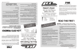
OWNER’S GUIDE
USE AND CARE MANUAL
MODEL SB5100
01-999-2534 Page 1
Safety
Operation
Maintenance
Trouble Shooting
Parts Replacement
READ THIS FIRST!
WARNING - TO REDUCE THE RISK
OF FIRE, ELECTRIC SHOCK OR INJURY TO
PERSONS, OBSERVE THE FOLLOWING
• Always disconnect electrical power to unit before
attempting to work on or service your cooler.
• Do NOT operate with evaporative pad removed.
• Do NOT use this unit as a step stool or ladder. Do not sit or
stand on this unit. Serious risk of personal injury or
property damage may occur.
• Do NOT operate this cooler (fan motor) with any solid-state
speed control device.
• Do NOT operate with pad frame removed. Do NOT
place ngers or any other objects inside the fan section.
Serious risk of personal injury or property damage may occur.
• Never wash your cooler cabinet with a garden hose, water
may harm motor and pump.
• Use of extension cord is not recommended.
NOTE:
• Do not use indoors on carpet or wood oor. Unit may leak
water and could damage ooring or create a slip hazard.
• Do not locate or operate cooler near exhaust or vent pipes
as odors or fumes may be drawn into unit.
• Your warranty does not cover shipping damage. Report all
shipping damage at once to store making the delivery.
• For future reference, record the serial number and
purchase date of your evaporative cooler here:
Serial #____________________________________________
Purchase Date:_____________________________________
Place of Purchase:___________________________________

01-999-2534 Page 2
CAUTION: the use of anode devices, chemical additives
or cooler cleaner treatments in this cooler will void the
warranty.
INTRODUCTION
Your Shop Blaster evaporative air cooler was thoroughly tested
and inspected before leaving the factory. This manual is your guide
to economical, trouble free comfort cooling over the years with
reasonable care and regular maintenance. Failure to follow these
instructions may damage your cooler, impair its operation, and/or
void the warranty.
Read it carefully.
PREPARATION
Unpacking the unit
Remove the pad frame by lifting up and pulling outwards. The oat
kit bag is located in the cooler bottom pan. Remove the oat kit
bag from the cabinet. Float kit contains the following items:
1. Float valve assembly
2. Float bracket
3. Garden hose adapter
4. Overow stand pipe
5. Drain Bushing Assembly
SET UP FOR USE
The Shop Blaster evaporative cooler may be lled manually with
the ll door or automatically with the oat valve and garden hose
adapter.
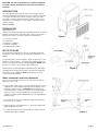
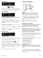
To Install oat valve and hose adapter. Attach the oat valve to the
cabinet as shown in gure 2. The garden hose adapter attaches to
the brass inlet tting on the oat valve (See gure 2). NOTE: Verify
that the hose washers are correctly in place before use.
Next install the overow stand pipe and drain bushing. Attach the
stand pipe, drain bushing, and washer in the hole in the drain pan
in the order shown in gure 3. NOTE: Verify that the washer is
correctly in place before use.
Water connection and oat adjustment
Move cooler to desired location (must be a level area for proper
operation of the cooler).
1. Connect water supply using a commercial grade water hose (not
supplied with cooler, obtained separately) to the adapter on the
oat valve and turn water on. CAUTION: water inlet pressure
should be limited to a maximum of 65 PSI to avoid rupturing the
water hose. If pressure exceeds this valve, an inline pressure
regulator should be installed (obtainable from a local plumbing or
hardware store).
2. Check that all connections are tight by visually inspecting hose,
oat valve, etc. for leakage.
3. Set oat valve for a water depth of 2.5". The oat is adjusted by
lightly bending the oat rod.
4. Do not insert garden hose into manual ll door; water may harm
the pump and void the warranty.
Figure 1
Figure 3
Figure 2

Motor and Blower check
Remove the pad frame by slightly lifting it from the bottom, pull
outwards until clear of cabinet bottom pan, then downwards until
frame clears cabinet top. Check motor mounting to be sure all
screws and nuts are tightened down properly. Rotate the blower by
hand to see that it moves freely without rubbing against housing.
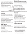
Belt Adjustment
Correct belt tension and alignment is important
as it cuts power consumption and prolongs life
of the belt and motor. When installing or
adjusting belt, loosen the motor adjustment bolts
and adjust for proper tension. Align belt vertically
by centering motor pulley in-line with blower pulley.
Do not adjust motor sheave turns.
Warning: Adjusting sheave turns will void warranty.
Drawer liners
Install the included drawer liners to protect the nish on the inside of
the drawers.
Electric Power
CAUTION:
• This cooler is designed for connection to 120 volt AC, 60 Hz
(cycle) power only. NOTE: Improper voltage will void the pump
and/or motor warranties and may cause serious personal injury or
property damage.
• This cooler must be plugged into a GFCI protected receptacle,
which has been properly installed in accordance with all local and
national codes. If you are not sure that the receptacle is GFCI
protected, consult with a qualied electrician.
• This cooler is equipped with a power cord having an equipment
grounding conductor and grounding plug. DO NOT attempt to
defeat this safety device by removing the grounding pin.
Cooler checkout and rst time start-up
Congratulations your cooler is complete and ready for use. Please
proceed to Pre-startup inspection checklist on before starting unit
for the rst time.
GENERAL INSPECTION
Pre-Start-up Inspection Checklist
• Cooler is on a level surface, casters locked to prevent
unnecessary movement (prevent spillage).
• Power supply cord is plugged into a GFCI protected receptacle;
cord is secure from accidental damage.
• Float valve installed.
• Water hose connected securely without leaks. Water faucet or
supply is turned on.
• Float adjusted for proper water level.
• Pad frame correctly installed.
• Pump impeller turns freely. Remove impeller cover (see page 5
“Cleaning Pump”) and check rotation.
• Fan, shaft, pulley and motor sheave set bolts/screws are snug.
• Motor sheave alignment okay; belt tension okay (see Belt
Adjustment for instructions).
01-999-2534 Page 3
Start-up Checklist
CAUTION: Never operate unit with pad frame removed. This
will result in an overloaded condition and may damage the fan
motor. The motor and pump have an internal automatic thermal
overload switch that will shut the motor and/or the pump off if
it overheats! The motor and/or pump can restart automatically
when they cool down.
To verify and check out the cooler installation on initial startup, the
following procedure should be followed.
• Push “COOL” switch to ON position (pump on).
• Verify that pump starts and pads are evenly wet.
• Push “FAN” switch to LOW position (low speed on).
• Observe that motor starts and runs. Check high-speed
function by turning “FAN” switch to HIGH (high speed on).
In case of trouble in any of these stages, refer to the
Troubleshooting chart on page 9.
Cabinet Inspection Checklist
After initial start-up and during periodic inspections, check for and/
or observe the following: Refer to the Troubleshooting Chart on
page 9 if necessary.
• Leaks from cabinet
• Observe cooler media for uneven wetting
• Conrm water level setting is correct.
• Verify full, even ow in water distribution system.
• Blower wheel / motor rotates freely, no unusual noises.
• Belt condition / tension / alignment.
• Check motor mounting and cabinet hardware.
Extended Shut-down (winterizing) checklist
Any time the unit will not be used for an extended period:
• Unplug the cooler power supply cord and secure it out of
the way on the rear of the unit to avoid damage.
• Move cooler to the area appropriate to dump water.
• Remove drain bushing assembly as shown in Figure 3
• Drain all of the water out of the cooler when not used for
prolonged periods, particularly at the end of the season
(winter).
OPERATING INSTRUCTIONS
Guidelines and location
Always make sure that the roll-around unit is operated
on a solid, level surface strong enough to hold its weight
(Unit can weigh up to 600 lbs. when full). Make sure the two
locking casters have been locked to prevent the cooler from
accidentally moving while in use. Use caution when rolling
the unit to avoid splashing or spilling of water. Always ensure all
drawers are closed and locked prior to moving the unit. Unless the
move is for a short distance, it is best to drain the unit, move
it and then rell it in its new location. For best results:
• Turn pump on a few minutes before starting the fan, this
allows the pads to pre-wet and avoids a blast of warm air.
• Turn pump off a few minutes before turning the fan off.
This will allow the pads to dry out, helping to prevent stale
or musty odors the next time the unit is started.
• Whenever possible, operate the fan on low speed for
maximum cooling.
• When cooling is not required, you can operate this unit by
turning on the fan only (leaving the pump turned off).

If a USB device or SD card is present, the radio will default to the
USB/SD mode, if no USB device or SD card is present, the radio will
default to line in mode.
To increase volume, press and hold on the unit or on the
remote.
To decrease volume press and hold on the unit or on the
remote.
To mute the output press on the remote.
Press on the remote to cycle through the equalizer options.
Press the button on the radio or on the remote to switch
between modes.
Available modes:
- Line In
- Bluetooth
- FM Radio
- USB/SD Card
To turn off the radio module press on the remote. Press
again to turn the radio module back on. Note: It is recommended to
unplug the entire ShopBlaster evaporative cooler unit if neither the
radio nor the cooler are being used.
USB/SD Card Mode:
This unit will support up to a 32 GB SD card and a 16 GB USB ash
drive.
The unit will automatically switch to this mode when an SD card or
USB ash drive is connected.
Press and on the module or and to select the desired
track.
Tracks can also be selected using the number pad on the remote.
Press on the module or on the remote to pause playback
and press it again to resume playback.
Press to repeat the current song.
Press on the remote to stop playback.
01-999-2534 Page 4
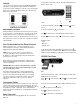
Controls
Rocker-type control switches are used to select the operating mode
of the cooler. These switches control fan speed (FAN-HIGH/OFF/
LOW) and the pump operation (COOL-ON/OFF). To eliminate a
rush of warm air when starting the cooler, be sure to turn the pump
(COOL) on for a few minutes before turning on the blower motor
(FAN) in low or high speed.
Maintenance Schedule
Regular maintenance and periodic inspection is a key to long and
successful service of your Shop Blaster Cooler. The cooler should
be serviced at least once a year, or more often if required. For
maximum efciency, longer life and appearance, every two months
during operation, the cooler should be inspected and cleaned.
Drain water from the unit every 8-10 hours of operation to minimize
scaling build up.
Note: Do Not Undercoat the Water Reservoir
Your cooler's water reservoir is nished with our Peblar XT®
appliance-type nish. It is so hard that asphalt-type cooler
undercoating will not stick to it. Undercoating will break free,
clogging the pump and water distributor.
NOTE: Do not use cooler cleaners, cooler treatments or
other chemical additives in this evaporative cooler. Use of
any additives or water treatment will void your warranty and
impair the life of the cooler.
Before starting any maintenance operation, read thoroughly
all operating and maintenance instructions and observe all
cautions and warnings.
CAUTION: Disconnect all electrical power to the cooler by
removing plug from receptacle before attempting to install,
open, or service your cooler.
Even while routinely inspecting or servicing the inside, the
cooler can be accidentally started. Keep all personnel away
from the cooler and electrical supply when you are working
on it. Before servicing or cleaning unit, switch “COOL” and
“FAN” to the OFF position and remove power cord from
receptacle.
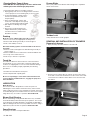
Convenience Outlet
A convenience outlet is located on the front of the unit. This outlet
is protected by a 3 Amp circuit breaker located directly above the
outlet. Do not attempt to plug in a device or combination of devices
that will draw more than 3 amps total. If the circuit breaker is
tripped, wait for the circuit breaker to reengage and then push the
switch to reset.
Stereo Operation
When the Shop Blaster unit is plugged in the radio screen will
display HI
CONTROL SWITCHES
EQ
MODE
M
STOP
EQ
MODE
M
STOP
EQ
MODE
M
STOP
EQ
MODE
M
STOP
EQ
MODE
M
STOP
EQ
MODE
M
STOP
EQ
MODE
M
STOP
EQ
MODE
M
STOP
EQ
MODE
M
STOP
EQ
MODE
M
STOP
EQ
MODE
M
STOP
EQ
MODE
M
STOP
EQ
MODE
M
STOP
EQ
MODE
M
STOP
EQ
MODE
M
STOP
EQ
MODE
M
STOP
EQ
MODE
M
STOP
EQ
MODE
M
STOP

Line-in Mode:
To use line in connect a device using a cord with a 3.5mm audio
connector. Volume can still be adjusted through the module but all
other controls need to be made on the connected device.
Bluetooth Mode:
Note: when using the Bluetooth mode ensure Wi-Fi is turned off on
the connected device as Wi-Fi and Bluetooth can interfere when
they are both running at the same time.
To connect to the radio module using Bluetooth, change the mode
of the Bluetooth. Using the device you intend to connect search
for Bluetooth devices. The name will be either BT-SPEAKER or
ShopBlaster.
When a device is connected to the radio module, no other devices
will be able to nd the radio module.
Press and on the module or and to select the desired
track.
Press on the module or on the remote to pause playback
and press it again to resume playback.
FM Radio Mode:
FM radio station setup:
The radio unit can search for stations by pressing while in FM
radio mode. This will set the available stations that the unit is able
to receive and assign a number to each station.
Once the stations have been set, press or on the unit to
cycle between the stations identied in the setting process.
Stations can also be selected using the number pad on the remote.
The selection can be made by either entering the number that was
assigned to the station or by entering the frequency of the station.
EX: To select the station that was assigned position 12 enter 12 with
the remote.
EX: To select 93.3 MHz enter 933 with the remote.
01-999-2534 Page 5
Remote Control Battery:
The remote control uses a CR2025 battery.
Cleaning
CAUTION: Never wash your cooler cabinet with a
garden hose; water may harm motor and pump. Motors
damaged by water are NOT covered under warranty.
All foreign materials, scale, salt deposits, lime, etc. can and
should be removed from bottom pan and other components.
Your cooler's long lasting nish can be brought to like-new
condition by using warm water and a soft cloth.
NOTE: Avoid using scouring pads, steel wool or wire
brushes, as these will damage the nish and encourage
corrosion.
Maintenance & Inspection
CAUTION: Disconnect all electrical power to the cooler
by removing the plug from the receptacle before
attempting to install, open, or service your cooler.
IMPORTANT: Before operating cooler at beginning of
each cooling season, turn cooler motor and pump motor
shafts by hand to make sure they turn freely. Failure to
do so may result in burning out motor.
Periodic inspection of your cooler will enhance the chance for long,
trouble-free service life. For maximum efciency, every two months
during operation, or any time the cooler is opened, the cooler
should be inspected. Some suggested items:
• Check for leaks from pad frames, cabinet, etc.
• Are there any dry spots on the media when cooler is in operation?
• Are bolts, nuts and set screws snug?
• Is bearing making unusual noises?
• Does the blower wheel turn freely?
• Is oat level set correctly?
• Is water in the bottom pan clean?
• Belt condition / tension / alignment?
Adjust Belt Tension
CAUTION: Disconnect all electrical power to the cooler
and insure that belt is not rotating before adjusting belt
tension.
Each time you inspect your cooler, be sure to check belt tension
on motor/blower assembly. Check belt condition and replace it if
frays or cracks appear. Check alignment of blower pulley with motor
pulley (see page 3).
EQ
MODE
M
STOP
EQ
MODE
M
STOP
EQ
MODE
M
STOP
EQ
MODE
M
STOP
EQ
MODE
M
STOP
EQ
MODE
M
STOP
EQ
MODE
M
STOP
EQ
MODE
M
STOP
EQ
MODE
M
STOP

01-999-2534 Page 6
2. To prevent breakage, carefully release
and remove impeller base plate from
the pump body.
3. Using a mild detergent solution and
clean cloth, clean deposits from pump
screen, around impeller and base plate.
4. Spin impeller to dislodge any foreign
material.
5. Remove any foreign material in the
adapter between the pump and hose,
or between the hose and the water
distributor assembly.
Drawer Slides
Twice yearly, lubricate the drawer slides with grease or equivalent
where shown below.
Draining
Drain the cooler cabinet (with power off) as follows:
1. Move cooler to the area appropriate to dump water.
2. Remove drain bushing assembly as shown in gure 3.
3. Drain, clean and dry reservoir.
Alternative draining options for units that will not be moved
frequently:
1. Remove overow stand pipe from drain bushing assembly as
shown in gure 3.
2. Attach suitable size hose and route it to the desired drain area.
3. Put a cap on the end of the hose.
4. Drain every 8-10 hours of operation.
Touch-Up
The hardness, adhesion and smoothness of the internal and
external nish on your cooler makes it extremely unlikely that
scratches or chipping will occur. In the event that nish damage
does occur, it should be promptly repaired by the following
procedures:
1. Sand the area around bare metal spots.
2. Prime and paint with a quality paint.
Do not use asphalt type cooler undercoat material in water
reservoir. Undercoat will break free, clogging the pump and
water distributor.
LUBRICATION
Motor Bearings
Some motors used in Shop Blaster coolers have ports for
lubricating the motor and are oiled at the factory. If the need for
oiling is indicated, see the motor nameplate for specic instructions
on re-lubricating the motor. Under normal use, these motors require
oiling about every 12 months of operation. Do Not Over-Oil.
Blower Shaft Bearing
Blower shaft bearings need periodic lubrication. They should be
checked 20-30 days after initial start-up of operation. The oil cups
on the bearings should be lled with a good grade of SAE 20W or
30W non-detergent oil when necessary. Under normal use, oiling is
required every three months of operation. Do Not Over-Oil.
Pump Bearings
The pump motor does not require lubrication.
Cleaning Water Pump & Hose
CAUTION: Do not allow pump to fall over and become
submerged; water will damage pump motor.
Clean water pump and hose assembly as follows:
1. Unplug pump cord, remove mounting bracket screw and
remove pump from cooler. Shake gently to remove water.
Toolbox Lock
Yearly, lubricate the lock with graphite.
REMOVAL AND INSTALLATION OF DRAWERS
Removal of drawers
1. Empty and fully extend the drawer to be removed.
2. Push the levers on both sides up or down to release the section
of the slide connected to the drawer from the section of the slide
connected to the cabinet. Pull the drawer out to remove it from
the cabinet.

Drawer Installation
Pull slides in box to full extension. Align the slides in from the box
with the slides on the drawer one at a time. Once both are aligned,
push the drawer completely into the box.
01-999-2534 Page 7
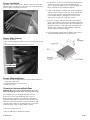
Drawer Slide Removal
1. Remove the drawer.
2. Drill out rivets holding the slide on the box using a 5/32 inch drill
bit.
3. Push slide towards the back of the box to remove.
Drill out rivet
Drawer Slide Installation
1. Position the slide in approximately the same vertical position as
the previous slide was in.
2. Pull slide towards the front of the box.
3. Replace the rivet.
Cleaning or Replacing Media Pads
CAUTION: Disconnect all electrical power to the cooler
before attempting to install, open, or service your cooler.
The condition of your cooler pads should be checked
at least once a year; at the beginning of the season is
best. However, your pads may need to be checked more
frequently, depending on local air and water conditions. For
instance, in areas where mineral content of the water is high
or the air is dusty, deposits may build up in the cooler pads,
restricting airow. Clean or replace pads as follows:
1. Disconnect power from unit.
2. Remove pad frame assembly from cabinet.
3. Lay pad frame on smooth, at surface with pad retainer up.
observe the location / placement of the pad retainer.
Remove retainer by sliding it out from under the pad frame
ange. Carefully remove and discard old pad.
4. Using a mild detergent, wash dirt and scale from pad frame
and rinse with fresh water. Check slots at top of pad frame
to be sure they are open and clear. Wire brushing is not
recommended. If nish is damaged or rusting is noted,
repair area as noted in the “Touch-Up” section.
5. Place the slot in the end of the new pad over the bottom
ange of the pad frame and push the pad down against the
ange until it stops. Gently push the top of the pad into the
pad frame. Slide the 1” thick pad on top of the large pad
already in place. Replace the pad retainer by sliding the
retainer under the pad frame anges.
6. Pre-soak pad (this will help with the wetting of the pad on
start-up) .Reinstall pad frame assembly into unit.

01-999-2534 Page 8
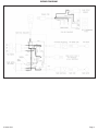
WIRING DIAGRAM

01-999-2534 Page 9
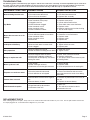
TROUBLESHOOTING:
The following guide is intended to help you diagnose and x some of the most commonly encountered problems; by no means does
this guide cover all of the possible problems you may encounter. If you cannot diagnose and correct the problem, or if it persists,
contact qualied service personnel. All electrical work should be done by, or with the help of, a qualied electrician.
PROBLEMS / SYMPTOMS POSSIBLE CAUSE CORRECTIVE ACTION
Water draining from the unit
1. Float valve out of adjustment
2. Float movement obstructed
3. Float valve non-functional
1. Adjust oat to 2-2-1/2" water depth.
2. Free oat from obstruction
3. Replace oat assembly
Dry Media
1. Pump intake clogged
2. Non-functional water pump
3. Clogged water line
4. Water distributor clogged
5. Non-functional switch
6. Non-functional wiring
7. Water turned off to cooler
1. Remove obstruction
2. Replace water pump
3. Locate and free obstruction
4. Clear debris from water distributor
5. Replace switch
6. Repair or replace non-functional wiring
7. Turn on water supply
Motor does not start or no air
delivery
1. Electrical power disconnected
2. Circuit breaker tripped or fuse blown
3. Non-functional motor
4. Non-functional switch
5. Broken belt
1. Check power receptacle and cord
2. Determine cause and correct
3. Replace motor
4. Replace switch
5. Replace belt
Inadequate air delivery
1. Excessive belt tension
2. Blower wheel loose on motor shaft
3. Pads clogged
1. Adjust belt tension
2. Tighten wheel set screw
3. Replace pads
Noisy operation
1. Blower rubbing on housing
2. Motor or blower mounting screws loose
1. Reposition wheel
2. Tighten screws
Musty or unpleasant odor
1. Stale or stagnant water in cooler
2. Media pads clogged or mildewed
3. Media pads not completely wet before
starting fan motor
1. Drain, clean, and ush reservoir
2. Replace media pads
3. Turn pump ON for several minutes prior
to starting cooler
Motor cycles on & off
1. Low voltage
2. Motor shaft tight or frozen
3. Pad frame or air outlet grille removed
1. Check voltage
2. Replace motor
3. Re-install pad frame or air outlet grille
No power at convience outlet
1. Electrical power disconnected
2. Circuit breaker on unit tripped
1. Check power receptacle and cord
2. Reset circuit breaker and ensure the
max amp draw on the outlet is not being
exceeded
Remote does not work
1. Remote does not have line of sight to
unit.
2. Remote battery is dead
1. Remove any obstructions in the way of
the unit
2. Replace the remote battery
Poor bluetooth reception
1. Signal blocked by obstructions
2. Interference from wi
1. Move unit
2. Turn wi off on the device that is
connected to the unit
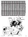
REPLACEMENT PARTS
When ordering replacement parts, always refer to the serial number and model number of your cooler. Use the part numbers listed in the
accompanying parts list, as illustrated in the diagrams for your model.

01-999-2534 Page 10
SB5100 - Replacement Parts List
Item Replacement Part Part Number
1 Switch Box Cover 05-004-0003
2 Louver Panel Assembly 05-001-0145
3 3" Celdek Media (Set of 2) 05-002-0427
4 Water Distributor Assembly 05-006-0193
5 Switch Box 05-007-0174
6 120V Motor Receptacle 05-007-0061
7 120V Pump Receptacle 05-007-0060
8 Blower Pulley 05-003-0059
9 Belt 05-003-0219
10 Pump - 120V 05-006-0221
11 Overow Standpipe Kit 05-006-0005
12 Float Valve Assembly 05-006-0001
13 Bearing Assembly (Set of 2) 05-003-0037
14 Blower Wheel 05-003-0034
15 Shaft 05-003-0001
16 Delrin Spacers (Pair) 05-003-0082
17 Motor 1/2 Hp, 120V 05-007-0175
18 Grille Handle Sleeve (Set of 2) 05-001-0146
19 Float Bracket 05-006-0186
20 Garden Hose Adapter 05-006-0242
21 Speaker 05-007-0176
22 Power Supply 05-007-0177
23 Amplier 05-007-0178
24 Inputs Module 05-007-0179
25 Circuit Breaker 05-007-0180
26 Duplex Outlet 05-007-0181
27 Outlet Cover 05-007-0182
28 Radio Remote Control (not shown) 05-007-0183
29 Toolbox Key (not shown) 05-008-0003
30 Toolbox Drawer Slides (not shown) 05-008-0004
31 Motor Sheave 05-003-0032
1
10
9
17
2
3
4
22
23
24
25
26
31
18
27
BLOWER ASSEMBLY
8
16
15
14
13
12
11
19
20
21
5
76
SB5100 - Replacement Parts List
Item
Replacement Part
Part Number
1
Switch Box Cover
05-004-0003
2
Louver Panel Assembly
05-001-0145
3
3" Celdek Media (Set of 2)
05-002-0427
4
Water Distributor Assembly
05-006-0193
5
Switch Box
05-007-0174
6
120V Motor Receptacle
05-007-0061
7
120V Pump Receptacle
05-007-0060
8
Blower Pulley
05-003-0059
9
Belt
05-003-0219
10
Pump 120V
05-006-0221
11
Overflow Standpipe Kit
05-006-0005
12
Float Valve Assembly
05-006-0001
13
Bearing Assembly (Set of 2)
05-003-0037
14
Blower Wheel
05-003-0034
15
Shaft
05-003-0001
16
Delrin Spacers (Pair)
05-003-0082
17
Motor 1/2 Hp, 120V
05-007-0175
18
Grille Handle Sleeve (Set of 2)
05-001-0146
19
Float Bracket
05-006-0186
20
Garden Hose Adapter
05-006-0242
21
Speaker
05-007-0176
22
Power Supply
05-007-0177
23
Amplifier
05-007-0178
24
Inputs Module
05-007-0179
25
Circuit Breaker
05-007-0180
26
Duplex Outlet
05-007-0181
27
Outlet Cover
05-007-0182
28
Radio Remote Control (Not Shown)
05-007-0183
29
Toolbox Key (Not Shown)
05-008-0003
30
Toolbox Drawer Slides (Not Shown)
05-008-0004
31
Motor Sheave
05-003-0032

01-999-2534 Page 11
Phoenix Manufacturing, Inc., Phoenix Arizona, extends this limited warranty to the original purchaser of this evaporative cooler.
What this warranty covers and for how long:
FIVE YEAR COVERAGE: Phoenix Manufacturing Inc. will exchange the cabinet only should any water leakage occur through the base assembly due to rust out, or as a result of
defect in material or workmanship during the rst ve years from the date of initial purchase.
THREE YEAR COVERAGE: applies to the fan motor if furnished by Phoenix Manufacturing Inc.
ONE YEAR COVERAGE: applies to all other components if furnished by Phoenix Manufacturing Inc. Phoenix Manufacturing Inc, at their discretion, will exchange or replace all
components should they fail as a result of a defect in material or workmanship during the rst year from date of initial purchase.
Media is a disposable item and has no warranty.
What this warranty does NOT cover:
PMI is not responsible for any damage or malfunction unless caused by a defect in material or workmanship. Determination of defects in materials or workmanship is at the sole
discretion of PMI or its appointed representative.
DAMAGE OR MALFUNCTION, WHICH IS NOT COVERED BY THIS WARRANTY, INCLUDES, BUT IS NOT LIMITED TO:
√ Pad media √ Abuse or misuse √ Worn belts √ Improper installation, maintenance or operation
√ Water damage to motor √ Transportation damage √ Acts of God
• Do not use anode devices, water from a water softener, cooler cleaners, cooler treatments or other additives in your cooler.
The use of any of these products will void your warranty and may impair the life of your cooler.
• This warranty does NOT cover evaporative coolers installed and operated outside the continental United States.
• PMI does NOT pay the cost of a service call to the site or installation to diagnose the cause of trouble.
• PMI does NOT pay the cost of labor to install the part, or mileage allowance to or from the site.
• PMI does NOT pay the freight / postage on any exchange or replacement parts.
• This warranty does NOT cover any failure, damage, or defect that results from unauthorized modication or service, or from the use of products or replacement parts other than
those from PMI, including, but not limited to motors and pumps.
To obtain service under this warranty:
Contact the dealer where you purchased your evaporative cooler. Include your name, phone number, address and zip code, the model and serial number of your evaporative cooler,
a copy of your proof of purchase, date of installation and a description of your problem.
If you are not able to locate your dealer, or in case of unsatisfactory warranty service from your dealer, please write the Warranty Department, PMI, 3655 E. Roeser Road, Phoenix,
Arizona, 85040. Include your name, phone number, address and zip code, the servicing dealer involved, the model and serial number of your evaporative cooler, a copy of your
proof of purchase, date of installation, and a description of your problem.
Replacement Parts:
All PMI replacement parts carry a 90-day warranty from date of purchase (or balance of original warranty, whichever is greater).
This warranty is the only warranty extended by PMI to consumer purchasers of evaporative coolers. PMI disclaims all other warranties, expressed or implied, that arise by the
operation of the law, except that implied warranties of merchantability or tness for a particular purpose are limited to the duration of the expressed limited warranty period. PMI shall
not be liable to any incidental or consequential damages, above the limitations or exclusions stated above which may have resulted from any alleged breach of warranty.
Some states do not allow limitations on how long an implied warranty lasts or the exclusion or limitation of incidental or consequential damages, the limitations or exclusions stated
above may not apply to you. This warranty gives you specic legal rights, and you may have other rights which vary from state to state.
Evaporative Cooler - Limited Warranty
Phoenix Manufacturing,Inc.Phoenix, Arizona, extiende esta garantía limitada al comprador original de este enfriador evaporativo.
Lo que esta garantía cubre y por cuanto tiempo:
Cobertura de cinco años Phoenix Manufacturing Inc intercambiará el gabinete, si es que fugas de agua ocurran a través del fondo debido a oxidación, como resultado de material defectuoso o de mano de obra
durante los primeros cinco años de la fecha de su compra inicial..
Cobertura de tres años se aplica a motor de ventilador si propoecionado por PMI.
Cobertura de un año se aplica a todos los componentes si fue proporcionado por PMI. PMI a su discreción, intercambiará o remplazará, todos los componentes si es que fallan como resultado de defectos en
material o mano de obra durante el primer año de la fecha de su compra inicial.
Paja es un articulo desechable y no tiene garantía.
Lo que NO cubre esta garantía:
PMI no es responsable por ningún daño o mal funcionamiento al menos que sea causado por defectos de material o mano de obra. Determinación de defectos de material o mano de obra es solamente a la
discreción de PMI o su representante designado.
DAÑOS DEBIDO A MAL FUNCIONAMIENTO QUE CUBRE ESTA GARANTIA INCLUYEN, PERO NO SE LIMITAN A :
√ Filtros (paja) √ Abuso o mal uso √ Bandas gastadas √ Impropia instalación, mantenimiento, u operación
√ Daño de agua al motor √ Daños de transportación √ Actos de Dios
• No use dispositivos de ánodos, agua de un sistema de agua blanda, limpiadores para enfriador, tratamientos para enfriador, u otros aditivos en su enfriador. El uso de cualquiera de estos productos anulará la
garantía y posiblemente acortar la vida de su enfriador.
• Esta garantía no cubre enfriadores instalados y operados fuera del continente de los Estados Unidos.
• PMI NO paga el costo de llamada de servicio a la instalación para diagnosticar la causa del problema.
• PMI NO paga el costo de labor para instalar la parte, o el costo del millaje hacia o del lugar.
• PMI NO paga por el costo de ete/postal o cualquier intercambio o reemplazo de partes.
• Esta garantía NO cubre ninguna falla daño, o defecto que resulte por modicación no autorizada o servicio, o por el uso de productos o partes de reemplazo que no sean de PMI incluyendo, pero no limitado a
motores y bombas.
Para obtener servicio bajo esta garantía :
Contacte su proveedor en donde compró su enfriador. Incluya su nombre, número de teléfono, dirección y zona postal, el modelo y número de serie de su enfriador evaporativo, una copia de prueba de
compra, fecha de instalación y descripción del problema.
Si no puede localizar su proveedor, o en caso de servicio de garantía insatisfactorio, favor de escribir Departamento de garantía, PMI, 3655 E. Roeser Road, Phoenix, Arizona, 85040. Incluya su nombre, número
de teléfono, dirección y zona postal, el taller de servicio envuelto, el modelo y número de serie de su enfriador evaporativo, una copia de prueba de compra, fecha de instalación y descripción del problema.
Partes de reemplazo :
Todos las partes de reemplazo de PMI cuentan con una garantía de 90 días desde la fecha de su compra (o el balance de la garantía original lo que sea más).
Esta es la única garantía extendida por PMI al consumidor que compra enfriadores por evaporación. PMI desconoce todas otras garantías, expresadas, que surjan por la operación de la ley, excepto que
garantías implicadas de comerciabilidad o conveniencia para un propósito particular son limitadas a la duración del limitado período de garantía expresado. PMI no deberá ser responsable por daños incidentales
o consecuentes, las limitaciones o exclusiones declaradas arriba que posiblemente hayan resultado de cualquier declaración de garantía rota.
Algunos estados no permiten limitaciones en que tanto el contenido de una garantía dure o la exclusión o limitación de daños incidentales o consecuentes, las limitaciones o exclusiones indicadas arriba es
posible que no se la aplique a usted. Esta garantía le da a usted derechos especícos legales, y es posible que usted tenga otros derechos que varían de un estado a otro.
Garantia Limitada - Enfriador Evaporativo
-
 1
1
-
 2
2
-
 3
3
-
 4
4
-
 5
5
-
 6
6
-
 7
7
-
 8
8
-
 9
9
-
 10
10
-
 11
11


en otros idiomas
- English: Aerocool SB5100A User manual
Artículos relacionados
Otros documentos
-
 PMI CTV1 Manual de usuario
-
 Brisa BW4502MX El manual del propietario
-
Champion AD2C71 Manual de usuario
-
-
Sears PD6801 Manual de usuario
-
Champion ESSICK 3000 DD El manual del propietario
-
Essick RWC46 Manual de usuario
-
Champion MasterCool ASA35 El manual del propietario
-
 Arctic Cove EVC501 Manual de usuario
-
 Arctic Cove EVC700-MBPM016 Guía del usuario


