Aspes AAS3012B Manual de usuario
- Tipo
- Manual de usuario

SPLIT TYPE ROOM AIR CONDITIONER
OPERATION MANUAL
AAS3012B
Read this manual carefully and keep it for future reference.
This appliance is filled with R32.

This appliance is intended for domestic use only.
All illustrations appeared in the manual are reference images, your device may differ.

WARNING:
·If the supply cord is damaged, it must be replaced by the manufacturer,its service agent or
similarly qualified persons in order to avoid a hazard.
·This appliance can be used by children aged 8 years and above and persons with reduced
physical, sensory or mentao capabilities or lack of experience and knowledge if they have
been given superivision or instruction concering use of the appliance in a safe way and
understand the hazards involved. Children shall not play with the appliance. Cleaning and
·The wiring method should be in line with the local wiring standard.
user maintenance shall not be made by children without supervision.
All the cables shall have got the European authentication certificate. During installation, when the
·connecting cables break off, it must be assured that the grouding wire is the last one to be broken off.
The explosion-proof breaker of the air conditioner should be all-pole switch. Distance between its two
contacts should not be no less than 3mm. Such means for disconnection must be incorporated in the
·Make sure installation is done according to local wiring regulation by professional persons.
·
·A leakage explosion-proof breaker must be installed.
Make sure ground connection is correct and reliable.
Read the precautions in this manual
carefully before operating the unit. This appliance is filled with R32.
Do not use means to accelerate the defrosting process or to clean, other than those
recommended by the manufacturer.
·
Keep this manual where the user can easily nd it.
The appliance must be stored in a room without continuously operating ignition sources (for
example: open flames, an operating gas appliance or an operating electric heater).
Do not pierce or burn.
·
·Be aware that refrigerants may not contain an odour.
·The appliance must be installed, operated and stored in a room with a floor area larger than
3 .
·
·
Do not use a refrigerant other than the one indicated on the outdoor unit(R32) when installing,
moving or repairing. Using other refrigerants may cause trouble or damage to the unit, and
personal injury.
The type of connecting wire is H07RN-F.
wiring.
9
1
2
8
5
10
Contents
PARTS AND FUNCTIONS
OPERATION
INDOOR UNIT INSTALLATION
MAINTENANCE
CAUTIONS
TROUBLE SHOOTING

Parts and Functions
Indoor Unit Remote controller
165. LOCK display
1Inlet 4Air Purifying Filter 2
(inside) 7
3
4
2Inlet grille
33Outlet
5Anion generator
(inside)
858Supplemented
Operation mode QUIET SLEEP electrical HEALTH TURBO
heating
Emergency Remote controller
Switch 15
17
6Vertical blade 13 FAN TIMER 14
(adjust left and
7Horizontal flap
(adjust up and down air flow right air flow) Display board CONFIRM
12 SMART CANCEL 20
Don't adjust it manually) 10
COOL HEAT DRY
11 16
EXTRA
21 SLEEP FUNCTION SWING 18
19
9TURBO/QUIET
1. Mode display 10 heating--- A-B yard---
air sending----horizontal swing
Operation mode SMART COOL DRY FAN HEAT
Remote controller
20.
CANCEL/CONFIRM button
Function: Setting and cancel to the
timer and other additional functions.
21. SLEEP button
Display
circulated
LO MED HI AUTO
Loading of the battery
1Remove the battery cover;
2Load the batteries as illustrated.
2 R-03 batteries, resetting key
(cylinder);
Outdoor Unit
3Be sure that the loading
is in line with the" + "/"-";
4Load the battery,then put on the cover again.
Note:
The distance between the signal transmission head and the rece-
iver hole should be within 7m without any obstacle as well.
When electronic-started type fluorescent lamp or change- over
type fluorescent lamp or wireless telephone is installed in the
room, the receiver is apt to be disturbed in receiving the signals,
so the distance to the indoor unit should be shorter.
Full display or unclear display during operation indicates the
batteries have been used up. Please change batteries.
If the remote controller can't run normally during operation, please
remove the batteries and reload several minutes later.
4
OUTLET CONNECTING PIPING AND ELECTRICAL WIRING
DRAIN HOSE
INLET
Please be subject to the actual produce purchased the
above picture is just from your reference
Hint:
Remove the batteries in case won't be in use for a long period.
1
6. TIMER OFF display
TIMER ON display
7. TEMP display
8. Additional functions display
9. TURBO/QUIET button
10. HEAT button
11. COOL button
12. SMART button
13. FAN SPEED button
14. TIMER button
15. POWER ON/OFF button
16. DRY button
17. TEMP/HOUR button
18. SWING button
19. EXTRA FUNCTION button
Function:
Health--- Healthy airflow position1
--- Healthy airflow position 2---
standard position --- / transform---
2. Signal sending display
3. SWING display
4. FAN SPEED display
Display board
1 Signal receiver
1
2
2 Setting temp.display

2. SWING
Press button. changes as follows: Pos.4
SWING
Press button again ,
vertical flap will stop over
present position,
the swing function will be cancelled
EXTRA
3.Press
FUNCTION button to choose the Pos.2 and Pos.3.
Operation
Base Operation
Emergency operation and test operation
Emergency Operation:
Use this operation only when the remote controller is defective
or lost, and with function of emergency running, air conditoner
can run automatically for a while.
When the emergency operation switch is pressed, the " Pi "
sound is heard once, which means the start of this operation.
When power switch is turning on for the first time and
emergency operation starts, the unit will run automatically in
1
Remote controller FAN TIMER
43
CONFIRM
SMART CANCEL
COOL HEAT DRY
2the following modes:
Pi
Room Timer
SLEEP EXTRA
FUNCTION SWING Designated Fan Operation
temperature temperature mode speed mode
TURBO/QUIET Above 23oC 26oCNo AUTO COOL
Below 23oC 23oCNo AUTO HEAT
It is impossible to change the settings of temp. and fan speed,It
is also not possible to operate in timer or dry mode.
Test operation:
Test operation switch is the same as emergency switch.
Use this switch in the test operation when the room
temperature is below 16oC, do not use it in the
normal operation.
Continue to press the test operation
switch for more than 5 seconds. After
you hear the "Pi" sound twice, release
your finger from the switch: the cooling
operation starts with the air flow speed "Hi".
Under this operation mode,the fan motor of indoor
Pi Pi
3.Select temp.setting
Press button
Every time the button is pressed, temp.setting
increase 1oC,if kept depressed, it will increase
rapidly
Every time the button is pressed, temp.setting
decrease 1oC,if kept depressed, it will
unit will run in high speed.
Air Flow Direction Adjustment
decrease rapidly
Select a desired temperature.
1.Vertical flap
Remote controller
4.Fan speed selection COOL/DRY/AUTO(Initial state):
HEAT(Initial state):
Press FAN button. For each press, fan speed
changes as follows:
Remote controller:
Pos.1
Pos.2
Pos.3
Pos.4
Pos.5
Display
circulated
LOW MED HI AUTO
(Autoswing)
(no)
Air conditioner is running under displayed fan speed.
When FAN is set to AUTO, the air conditioner
automatically adjusts the fan speed according to room
temperature.
Operation Remote
Mode Controller Note
Under the mode of smart operation, air conditioner will
automatically select Cool or Heat operation according to
room temperature. When FAN is set to AUTO the air
conditioner automatically adjusts the fan speed according
to room temperature.
SMART
Cooling only unit do not have displays and functions
related with heating
COOL When adjusting the flap by hand,turn off the unit.
When humidity is high,condensate water might occur
adjusted to left or at air outlet if all vertical louvers are right.
It is advisable not to keep horizontal flap at downward
position for a long time in COOLor DRY mode ,
otherwise, condensate water might occur.
Note:
When restart after remote turning off, the remote controller
controller will automatically memorize the previous set swing position.
In DRY mode , when room temperature becomes lower
than temp.setting+2oC, unit will run intermittently at LOW
speed regardless of FAN setting.
DRY
In HEAT mode, warm air will blow out after a short
period of the time due to cold - draft prevention function.
When FAN is set to AUTO, the air conditioner automatically
adjusts the fan speed according to room temperature.
HEAT
In FAN operation mode , the unit will not operate in COOL or
HEAT mode but only in FAN mode, AUTO is not available in
FAN mode. And temp. setting is disabled. In FAN mode,
sleep operation is not available.
FAN
2
1. Unit start
Press ON/OFF on the remote controller, unit starts.
2. Select operation mode
COOL button:Cooling mode
HEAT button: Heating mode
DRY button: Dehumidify mode

Operation
Sleep Operation
PrePress SLEEP
button to enter sleep function
Note
When TIMER function is set, the sleeping function can’t be
set up .After the sleeping function is set up,if user resets
TIMER function, the sleeping function will be cancelled; the
machine will be in the state of timing-on.
TURBO/QUIET Operation
When you need rapid heating or cooling, you can use TURBO function.
When silence is needed for rest or reading,you can use QUIET function
Press TURBO/QUIET button, the remote controller will show
and then achieve to the TURBO function. Press again this
,
TURBO/QUIET button, the remote controller will show button, th
and then achieve to the QUIET function. Press again this
TURBO/QUIET button , the QUIET function will be cancelled.
SLEEP operation starts SLEEP operation stops
Approx.6hrs Note
During TURBO operation, in rapid HEAT or COOL mode ,
the room will show inhomogeneous temperature distribution.
Long period QUIET operation will cause effect of not too
cool or not too warm.
1 hr Rises 1OC
1 hr Rises 1OC
Temp.setting Unit stop
In COOL, DRY mode
In HEAT mode
2.
1 hours after SLEEP mode starts,temp will become 2O
C
lower than temp.setting.After another 1 hours,temp
decrease by 2OC futher.After more another 3 hours,temp.
rises OC
by 1 futher.The unit will run for further 3 hours then
stops.Temp.is lower than temp. setting so that room
temperature won’t be too high for your sleep.
Temp.setting Unit stop
1 hr Decreases 2OC
1 hr Decreases 2OC
3 hrs
3 hrs Rises 1OC
SLEEP SLEEP
operation starts operation stops
In HEAT mode
3. In SMART mode
The unit operaters in corresponding sleep mode
adapted to the automatically selected operation mode.
3
4. In FAN mode
It has no SLEEP function.
5.Set the wind speed change when sleeping
If the wind speed is high or middle before setting for the
sleep, set for lowing the wind speed after sleeping.
If it is low wind, no change.
HEALTH Operation
(This function is unavailable on some models.)
PressPre EXT
s RA
F
sUNCTION
button to enter additional options, when
cycle display tocycle di , will flash. And then press CONFIRM
CANCEL
enter to health function.
The anion generator in the airconditioner can generate
a lot of anion effectively balance the quantity of position
and anion in the air and a
●
lso to kill bacteria and speed
up the dust sediment in the room and finally clean the
air in the room.
Operation Mode
1 .. In COOL, DRY mode
1 hours after SLEEP mode starts,temp.will become 1O C
higher than temp.setting.After another 1 hours,temp.rises
OC
by 1 futher.The unit will run for further
6 hours then stops
T emp. is higher than temp.setting so that room temperature
won’t be too low for your sleep.

Operation
BLANK
1.After unit starts, select your desired operation mode.
2.Press TIMER button to change TIMER mode. Every
time the button is pressed, display changes as follows:
Remote controller:
TIMER ON TIMER OFF TIMER ON-OFF
Then select your desired TIMER mode (TIMER ON or
TIMER OFF or TIMER ON-OFF). " "or " "will flash.
3.Press / button to set time.
Press the button for each time, setting time in the first
12 hours increased by 0.5 hour every time, after 12
hours,increased by 1 hour every time.
Press the button for each time, settiing time in the first
12 hours decreased by 0.5 hour every time, after 12
hours,decreased by 1 hour every time.
It can be adjusted within 24 hours.
0.5h 0.5h 0.5h 0.5h
time ON or OFF button will not flash any more.
5.Cancel timer setting
Press the timer button by times until the time display
eliminated.
Hints:
After replacing batteries or a power failure happens, time
setting should be reset.
According to the Time setting sequence of TIMER ON or
TIMER OFF, either Start-Stop or Stop-Start can be achieved.
button and confirm the
4.Confirm timer setting
After adjust the time,press
Press button to enter additional options,Press this
button continuously, the louvers location will cycle between
in the following three locations, to choose the swing location
what you needed,and then press button to confirm.
Timer On/Off On-Off Operation
All the products are in conformity with the following
European provision:
RoHS
Your air conditioning product is marked with this
symbol.This means that electrical and electronic
products shall not be mixed with unsorted
household waste. Do not try to dismantle the
system yourself : the dismantling of the air
The products are fulfilled with the requirements in the
directive 2011/65/EU of the European p arliament and of
council on the Restriction of the use of Certain Hazardous
Substances in Electrical and Electronic Equipment (EU
RoHS Directive)
WEEE
In accordance with the directive 2012/19/EU of the European
parliament, herewith we inform the consumer about the dis-
posal requirements of the electrical and electronic products.
DISPOSAL REQUIREMENTS:
Contains fluorinated greenhouse gases
A
R32
1= kg
B
22= kg
C
1
1+2= kg
D
F E
This product contains fluorinated greenhouse gases.
Do not vent into the atmosphere.
Refrigerant type:R32
GWP* value:675
GWP=global warming potential
Please fill in with indelible ink,
and
on the refrigerant charge label supplied with the product.
The filled out label must be adhered in the proximity of the product
charging port (e.g. onto the inside of the stop value cover).
A contains fluorinated greenhouse gases
B factory refrigerant charge of the product: see unit name plate
C additional refrigerant amount charged in the field
D total refrigerant charge
E outdoor unit
F refrigerant cylinder and manifold for charging
EUROPEAN REGULATIONS
CONFORMITY FOR THE MODELS
IMPORTANT INFORMATION REGA-
RDING THE REFRIGERANT USED
Healthy airflow Operation
conditioning system,treatment of the refrigerant, of oil and of
other part must be done by a qualified installer in
accordance
with relevant local and national legislation. Air conditioners
must be treated at a specialized treatment facility for reuse,
recycling and recovery. By ensuring this product is disposed
of correctly, you will help to prevent potential negative cons-
equences for the environment and humen health. Please
contact the installer or local authority for more information.
Battery must be removed from the remote controller and dis-
posed of separately in accordance with relevant local and
nationl legislation.
1.Press to starting
Setting the comfort work conditions.
2.The setting of healthy airflow function
4.In cooling and dry, using the air conditioner for a long
time under the high air humidity, condensate water may
occur at the grille .
3.The cancel of the healthy airflow function
Press button to enter additional options,Press this
button continuously, the louvers location will cycle between
in the following three locations again,and then press
button to cancel.
Notice: Do not direct the flap by hand. Otherwise, the
grille will run incorrectly. If the grille is not run correctly, stop
for a minute and then start, adjusting by remote
controller.
Note:
1.After setting the healthy airflow function, the position
grill is fixed.
mode.
mode.
2.In heating, it is better to select the
3.In cooling, it is better to select the
TIMER OFF-ON
Healthy
airflow
upwarder
Healthy
airflow
downwarder
Present
position
4
2014/53/EU(RED) 2014/517/EU(F-GAS)
2009/125/EC(ENERGY)
2010/30/EU(ENERGY)
2006/1907/EC(REACH)
CONFIRM
CANCEL
EXTRA
FUNCTION
EXTRA
FUNCTION
CONFIRM
CANCEL
CONFIRM
CANCEL
Climate:T1 Voltage:220~240V
CE

Indoor Unit Installation
Driver Torque wrench
(17mm,22mm,26mm)
Nipper
Reamer
Hacksaw Pipe cutter
Gas leakage detector or
soap-and-water solution
Hole core drill Flaring tool
Spanner(17,19 and 26mm) Knife
Measuring tape
Necessary Tools for Installation Power Source
Before inserting power into receptacle, check the voltage without
fail.
The power supply is the same as the corresponding nameplate.
Install an exclusive branch circuit of the power.
A receptacle shall be set up in a distance where the power cable
can be reached.Donotextendthecablebycuttingit.
Selection of Installation Place
Place, robust not causing vibration, where the body can be
supported sufficiently.
ƽ
Place, not affected by heat or steam generated in the vicinity,
where inlet and outlet of the unit are not disturbed.
ƽ
Place, possible to drain easily, where piping can be conne-
cted with the outdoor unit.
ƽ
Place,wherecoldaircanbespreadin a roomentirely.
ƽ
Place, nearby a power receptacle, with enough space around.
ƽ
Place where the distance of more than lm from televisions,
radios, wireless apparatuses and fluorescent lamps can be
left.
ƽ
In the case of fixing the remote controller on a wall, place
where the indoor unit can receivesignalswhenthefluore-
scent
ƽ
lamps in the room are lightened.
ƽ
ƽ
ƽ
The distance between the indoor unit and the floor should be more than 2m.
more than
10cm
more than 15cm
more than 10cm
Th e model s adopt HF C refrigerant R32
Arrangement of piping
directions
Rear left
Left Rear
right
Right
Below
Attention must be paid to
the rising up of drain hose
Please be subject to the actual product purchased,the above picture is just for your reference.
If using the left side drain pipe, make sure the hole is got through.
Drawing for the installation of indoor units
5

Indoor Unit Installation
[ Left Left-rearpiping ]
Fitting of the Mounting Plate and Positioning of the wall HoleIn case of left side piping, cut away, with a nipper, the lid for left
piping.
In case of left-rear piping, bend the pipes according to the piping
direction to the mark of hole for left-rear piping which is marked on
heat insulation materials.
When the mounting plate is first fixed
Indoor/outdoor electric cable
Heat insulation
material Piping
Lid for right Pipe supporting
piping Drain hose plate
Lid for left piping
Lid for under piping pipe
Fix with adhesive tape
Indoor/outdoor electric cable and drain hose must be bound with
efrigerant piping by protecting tape.
[ Other direction piping ]
Cut away, with a nipper, the lid for piping according to the piping
direction and then bend the pipe according to theposition of wall
hole. When bending, be careful not to crash pipes.
Connect beforehand the indoor/outdoor electric cable, and then
pull out the connected to the heat insulation of connecting part
specially.
Fixing the indoor unit body
Hang surely the unit body onto the upper
notches of the mounting plate. Move the body
from side to side to verify its secure fixing.
In order to fix the body onto the mounting
plate,hold up the body aslant from the
underside and then put it down perpendicularly. mounting plate
Unloading of indoor unit body
Fix to side bar and lintel a mounting bar, Which is separately sold, and
then fasten the plate to the fixed mounting bar.
Refer to the previous article, “ When the mounting plate is fi rst fixed “,
for the position of wall hole.
When you unload the indoor unit,please use your hand to arise
the body to leave agraffe,then lift the bottom of the body outward
slightly and lift the unit aslant until it leaves the mounting plate.
Making a Holeon the Wall and Fitting the Piping Hole Cover
Make a hole of 60 mm in diameter, slightly descending to outside the wall
Install piping hole cover and seal it off with putty after installation
Wall hole
agraffe mounting plate
Ø60mm
Connecting the indoor/outdoor Electric Cable
Indoor side Outdoor side
Thickness of wall
(Section of wall hole) G Piping hole pipe Removing the wiring cover
Installation of the Indoor UnitRemove terminal cover at right bottom corner of
indoorunit, then take off wiring cover by removing
its screws.
Drawing of pipe
[ Rearpiping ]
Draw pipes and the drain hose, then fasten them with the adhesive tape 6
1. Insert the drain hose into the dent of heat insulation materials of
indoor unit.
2. Insert the indoor/outdoor electric cable from backside of indoor
unit,and pull it out on the front side, then connect them.
3. Coat the flaring seal face with refrigerant oil and connect pipes.
Cover the connection part with heat insulation materials closely,
and make sure fixing with adhesive tape
B=
Ø
60mm B=
Ø
60mm
20T
A=130mm C=110mm
When the mounting plate is fixed side bar and lintel
1. Carry out, based on the neighboring pillars or lintels, a proper leveling
for the plate to be fixed against the wall, then temporarily fasten the plate
with one steel nail.
2. Make sure once more the proper level of the plate, by hanging a thread
with a weight from the central top of the plate, then fasten securely the
plate with the attachment steel nail.
3. Find the wall hole location A/C using a measuring tape
35mm
35mm

1.Insertfromoutsidetheroomcableintoleftside of thewall
hole, in which the pipe has already existed.
2. Pull out the cable on the front side, and connect the cable
making a loop.
Insertthecablefromtheback
ƽ
side of the unit, then pull it out on the front side.
Loosen the screws and insert
ƽ
the cable ends fully into terminal block, then
tighten the screws.
Pull the cable slightly to
ƽ
make sure the cables have been properly inserted and
tightened.
After the cable connection,
ƽ
never fail to fasten the connected cable with the
wiring cover.
When connecting the cable after installing the indoor unit
When connecting the cable before installing the indoor unit
Note:
To Outdoor unit
Code
indication Trouble description Analyze and diagnose
E1
E2
E4
E7
E14
Heat-exchange
sensor failure
Indoor EEPROM
error
Communication
fault between
indoor and outdoor
units
Indoor fan motor
malfunction
Operation halt due to breaking
of wire inside the fan motor;
Operation halt due to breaking
of the fan motor lead wires;
Detection error due to faulty
indoor unit PCB;
Indoor unit- outdoor unit signal
transmission error due to wiring
error;
Faulty PCB;
Faulty EEPROM data;
Faulty EEPROM;
Faulty PCB;
Faulty connector connection;
Faulty thermistor;
Faulty PCB;
Room temperature
sensor failure
The power source must be exclusively used for air
ƽconditioner.
In the case of installing an air conditioner in a moist place,
ƽplease install
an ea
For installation in other places, use a circuit breaker as far
ƽas possible.
Pipecuttingiscarriedoutwith a pipecutterandbursmust beremoved.
After inserting the flare nut, flaring work is carried out.
Cutting and Flaring Work of Piping
Conventionalflare tool
Clutch-type clutch-type(Rigid-type) Wing-nut type (Imperial-type)
A 0~0.5mm 1.0~1.5mm 1.5~2.0mm
rth leakage breaker.
Lean Damage of flare Partial Too outside
Correct Incorrect
On Drainage
It becomes
high midway. The gap with the
ground is too small.
There is the bad
smell from a ditch
It waves.
The end is imm-
ersed in water.
Pleaseinstallthedrainhosesoastobedownwardslopewithoutfail.
Please don’t do the drainage as shown below.
ƽ
ƽ
Please pour water in the drain pan of the indoor unit, and
ƽ
is carried out surely to outdoor.
In case that the attached drain hose is in a room, please
ƽapply heat
insulation to
Less than
5cm
confirm that
drainage
it without fail.
Crack
Indoor unit
CheckItemsforTestRun
Gasleakfrompipeconnecting?
Heat insulation of pipe connecting?
Are the connecting wirings of indoor and outdoor firmly
Is the connecting wiring of indoor and outdoor firmly fixed?
Is drainage securely carried out?
Is the earth line securely connected?
Is the indoor unit securely fixed?
Is power source voltage abided by the code?
Is there any noise?
Is the lamp normally lighting?
Arecoolingandheating(wheninheatpump)performednormally?
Is the operation of room temperature regulator normal?
Please kindly explain to our customers how to
operate through the instruction manual.
inserted to the terminal block?
Ƶ
Put check mark in boxes
Flare tooling die 1.Cut pipe 2.Remove burs
3.Insert the flare nut 4.Flare pipe
ƽ
ƽ
On Drainage
Check for Installation and Test Run
7
When connecting the cable, confirm the terminal number of indoor and
outdoor units carefully. If wiring is not correct, proper operation can not
be carried out and will cause defect.
4G1.0mm
2
(Other models)
Connecting wiring
4G1.5mm
2
(AAS3012B)
If the supply cord is damaged, it must be replaced by the manufacturer
or its service agent or a similar qualified person. The type of connecting
wire is H07RN-F.
If the fuse on PC board is broken please change it with the type of
3.15A/250VAC (Indoor).
The wiring method should be in line with the local wiring standard.
After installation, the power plug should be easily reached.
A breaker should be incorporated into fixed wiring. The breaker should
be all-pole switch and the distance between its two contacts should be
not less than 3mm.
Power Source Installation
Flare tool for R32

Maintenance
Setting of proper room
temperature
Close doors and windows
during operation
If the unit is not to be used
for a long time, turn off the
power supply main switch.
Use the timer effectively
Use the louvers effectively
Do not block the air inlet
or outlet
Proper
temperature
During cooling operation
prevent the penetration
of direct sunlight with
curtain or blind
OFF
Remote Controller Indoor Body
1.Open the lnlet Grille
2.Detach the standard air filter
3.Attach Air Purifying Filter
4.Attach the standard air filter
(Necessary installation)
5.Close the Inlet Grille
Close the Grille surely
Slide the knob slightly upward to
release the filter, then withdraw it.
Put air purifying filter appliances into the
right and left filter frames.
NOTE:
The photocatalyst air purifying filter will be solarized in fixed
time. In normal family, it will be solarized every 6 months.
Prop up the inlet grille by using a
small device named grille-support
ATTENTION:
Please keep the bacteria-killing medium air purifying filter in
avoid long time directly sunshine
when you stop using it,or its ability of sterilization will be
reduced.
The bacteria-killing medium air purifying filter will be used
for a long time,no need for replacement. But in the period
of using them ,you should remove the dust frequently by
which located in the right side of
the indoor unit.
using vacuum cleaner or flaping them lightly,otherwise ,
its performance will be affected.
the cool and dry conditions
For Smart Use of The Air Conditioner
Replacement of Air Purifying Filter
The white side of the photocatalyst air purifying filter
face outside,and the black side face the unit The green
side of the bacteria-killing medium air purifying filter face
outside,and the white side face the unit.
Do not usewater,wipe the controller
with a dry cloth.Do not use glass
cleaner or chemical cloth.
wipe the air conditioner by using a
soft and dry cloth.For serious stains,
use a neutral detergent diluted with
water.Wring the water out of the
cloth before wiping,then wipe off the
detergent completely.
Air Filter cleaning
Open the inlet grille by pulling it upward.
Remove the filter.
Clean the filter.
Attach the filter.
Close the inlet grille.
Push up the filter's center tab slightly until it is
from the stopper, and remove the filter downward.
Use a vacuum cleaner to remove dust, or wash the filter with
water.After washing, dry the filter completely in the shade.
Attach the filter correctly so that the "FRONT" indication
facing to the front.Make sure that the filter is
fixed behind the stopper.If the right
attached correctly, that
Do not use the following for cleaning
Gasoline,benzine, thinner or cleanser
ay damage the coating of the unit. Hot water over 40OC(104OF) may
discoloring or deformation.
Once every
two weeks
mcause
released
is
completely
and left filters are not
may cause defects.
Detach old Air Purifying Filter
8

the power supply cord
and so on.
2.Do not install in the place where there is any
possibility of inflammable gas leakage around the unit.
3.Do not get the unit exposed
to vapor or oil steam.
Cautions
Please call Sales/Service Shop for the Installation.
Do not attempt to install the air conditioner by yourself because improper works
may cause electric shock, fire, water leakage.
Connect the earth
cable.
earthing
WARNING
When abnormality such as burnt-small found,
immediately stop the operation button and
contact sales shop.
OFF
Use an exclusive
power source
with a circuit
breaker
ENFORCEMENT
Connect power supply cord
to the outlet completely Use the proper voltage
Do not use power supply
cord in a bundle. Take care not to damage
the power supply cord.
1.Do not use power supply cord extended
or connected in halfway
STRICT
ENFORCEMENT
STRICT
STRICT
ENFORCEMENT PROHIBITION
PROHIBITION
PROHIBITION
PROHIBITION
Do not start or stop the
operation by disconnecting
Do not channel the air flow directly
at people, especially at infants or
the aged.
Do not try to repair or
reconstruct by yourself.
Do not use for the purpose of storage of
food, art work, precise equipment,
breeding, or cultivation.
CAUTION
Take fresh air occasionally especially
when gas appliance is running at the
same time.
PROHIBITION
STRICT
ENFORCEMENT
Do not operate the switch with
wet hand.
PROHIBITION
PROHIBITION
PROHIBITION PROHIBITION
PROHIBITION
Do not install the unit near a fireplace
or other heating apparatus. Check good condition of the
installation stand
Do not pour water onto the unit
for cleaning
PROHIBITION
Do not place animals or plants in
the direct path of the air flow Do not place any objects on or
climb on the unit. Do not place flower vase or water
containers on the top of the unit.
Do not insert objects into the air
inlet or outlet.
PROHIBITION
PROHIBITION
PROHIBITION
STRICT
ENFORCEMENT
Check proper
installation of the
drainage securely
WARNING
9

Trouble shooting
Normal
Performance
inspection
Noise is heard
Phenomenon Cause or check points
The system
immediately.
Smells are
generated.
Mist or steam are
Multiple
check
Poor cooling
When unit is stopped, it won't restart
elapsed to protect the system.
When the electric plug is pulled out
and reinserted, the protection circuit
During unit operation or at stop,
a swishing or gurgling noise may
(This noise is generated by
refrigerant flowing in the system.)
During unit operation, a cracking
noise may be heard.This noise is
temperature changes.
Should there be a big noise from
filter may be too dirty.
This is because the system
circulates smells from the interior
During COOL or DRY operation,
This is due to the sudden cooling
Is power plug inserted?
Is there a power failure?
Is fuse blownout?
Is the air filter dirty?
Are there any obstacles before
Is temperature set correctly?
Are there some doors or
Is there any direct sunlight
through the window during the
Are there too much heat sources
or too many people in the room
In dry mode,
fan
speed can’t be
changed.
In DRY mode, when room temperature
setting+2 oC,unit will run
regardless of FAN setting.
during cooling operation?
cooling operation?(Use curtain)
windows left open?
inlet and outlet?
Normally it should be cleaned
every 15 days.
intermittently at LOW speed
becomes lower than temp.
indoor unit may blow out mist.
of indoor air.
air such as the smell of furniture,
paint, cigarettes.
air flow in unit operation, air
generated by the casing expanding
or shrinking because of
be heard.At first 2-3 minutes after
unit start, this noise is more noticeable.
will work for 3 minutes to protect the
air conditioner.
immediately until 3 minutes have
Cautions
3. If the fuse of indoor unit on PC board is
it with the type of T. 3.15A/ 250V outdoor
broken,change it with the type of T.25A/250V
The refrigerating circuit is leak-proof.
1.Applicable ambient temperature range:
Specifications
The machine is adaptive in following situation
The power plug and connecting cable acquired the local
2. If the power supply cord is damaged, it must be replaced
manufacturer qualified
person.
4. The wiring method should be in line with
the local wiring
5. After installation, the power plug should
be easily reached.
6. The waste battery should be disposed
properly.
7. The appliance is not intended for use
persons
without supervision.
8.Young children should be supervised
with
the appliance.
9. Please employ the proper power plug,
cord.
11.In order to protect the units,please turn
30 seconds
later, cutting off the power.
10.
or its service agent or a similar
broken,please
. If the fuse of
standard.
by young children or
to ensure that they
which fit into the
must have
off the A/C first,
Before asking for service, check the following
first.
blown out.
does not restart
by the
change
unit is
infirm
do not play
power supply
attestation.
and at least
Do not obstruct or cover the ventilation
conditoner.Do not put fingers
inlet/outlet and swing louver.
This appliance is not intended for use by persons (including children)
with reduced physiced, sensory or mental capabilities or lack of
experience and knowledge, unless they have been given supervision
or instruction concerning use of appliance by person responsible for
their safety. Children should be supervised to ensure that they do not
play with the appliance.
grille of the air
or any other things into the
10
Maximum:D.B 35
o
C
Indoor
Minimum:D.B 21
o
C
Cooling
Maximum:D.B 43
o
C
Outdoor
Minimum: -10
o
C
Maximum:D.B 27
o
C
Indoor
Minimum: D.B 10
o
C
Heating Outdoor
Maximum:D.B 24
o
C
Minimum:D.B -15
o
C
D.B

Lea las precauciones en este
manual detalladamente antes de
utilizar la unidad.
Este aparato está cargado de
R32.
Guarde este manual en el lugar donde el usuario puede encontrar fácilmente.
ADVERTENCIA:
No utilice otros métodos para acelerar el proceso de desescarche o para limpiar, aparte de los recomendados
por el fabricante.
El aparato se debe almacenar en una habitación sin fuentes de ignición en operación continua (por ejemplo:
llamas abiertas, un aparato de gas en operación o un calentador eléctrico en operación).
No perfore ni queme.
Tenga en cuenta que posiblemente el refrigerante no contenga olor.
El aparato se debe instalar, operar y almacenar en una habitación con una superficie mayor de 1,2m2.
Si el cable de alimentación está dañado, se debe reemplazar por el fabricante, su agente de servicio o el
personal calificado similar con el fin de evitar el peligro.
Este aparato se puede utilizar por el niño de 8 años o mayor y la persona con reducida capacidad física,
sensorial o mental o falta de experiencia y conocimiento si están bajo la supervisión o saben las instrucciones
de usar el aparato con una manera segura y saben los peligros involucrados. Los niños no deben jugar con el
aparato. La limpieza y el mantenimiento del aparato no se realizarán por los niños sin supervisión.
El método de cableado debe cumplir el estándar local de cableado.
El tipo del cable de conexión es H07RN-F.
Todos los cables deben haber conseguido el certificado de autenticación europea. Durante la instalación,
cuando los cables de conexión se rompen, deben asegurar que el cable de tierra es el último de romperse.
El interruptor del aire acondicionado debe ser el interruptor multipolar; y la distancia entre sus dos contactos
no debe ser no inferior a 3 mm. Tales métodos para desconexión deben ser incorporados en el cableado.
Asegúrese de que la instalación está realizada de acuerdo con la regulación local de cableado por personas
profesionales.
Asegúrese de que la conexión a tierra es correcta y fiable.
Deben instalar un interruptor de circuito y un interruptor de fuga a tierra.
No utilice el refrigerante que no sea el indicado en la unidad exterior (R32) al instalar, mover o reparar. El
uso de otros refrigerantes puede causar problemas o daños a la unidad y lesiones personales.
El tipo del cable de conexión es H07RN-F.
9
1
2
8
5
10
Contenido
PARTES Y FUNCIONES
FUNCIONAMIENTO
INSTALACIÓN DE LA UNIDAD INTERIOR
MANTENIMIENTO
PRECAUCIONES
RESOLUCIÓN DE PROBLEMAS

Componentes y funciones
Unidad interior
Unidad exterior
TUBOS DE CONEXIÓN Y CABLEADO
SALIDA DE AIRE
ELÉCTRICO
ENTRADA DE AIRE MANGUITO DE DRENAJE
Recuerde que la ilustración anterior podría no reflejar
fielmente el producto adquirido y debe utilizarse únicamente
como referencia.
4
8. Indicador de funciones adicionales
Mando a distancia
Instalación de las pilas
Instale las pilas y vuelva a colocar de nuevo la tapa.
Nota:
Extraiga la tapa de las pilas;
En la figura se muestra el modo
de carga de las pilas. 2 pilas
R-03, botón reinicio (botella);
Asegúrese de respetar los signos
"+" y "-";
3
1
2
4
Modo de
funcionamiento
SILENCIO SUELO
La distancia entre el cabezal de transmisión de la señal y el orificio del
receptor debe ser de unos 7 m sin obstáculos.
Si se instalan lámparas fluorescentes o se utilizan teléfonos inalámbricos
en la sala, el receptor podría resultar perturbado al recibir las señales, por
lo que la distancia hasta la unidad interior deberá ser menor.
Si se activan todos los indicadores de la pantalla o no es posible
visualizarlos correctamente durante el uso, es señal de que las pilas se han
agotado. Por favor, cambie las pilas.
Si el mando a distancia no funciona normalmente durante su uso,
extraiga las pilas y vuelva a instalarlas pasados unos minutos.
eléctrico SALUDABLE
Ayuda con calor INTENSO
Mando a
distancia
9. Botón TURBO/QUIET
10. Botón CALOR
11. Botón FRÍO
13. Botón VENTILADOR
14. Botón TEMPORIZADOR
12. Botón SMART
1. Indicador de modo
20. Botón CANCELAR/CONFIRMAR
Función: establecer y cancelar el
temporizador y otras funciones
adicionales.
21. Botón SLEEP
Modo de
funcionamiento
AUTOMÁTICO SECOREFRIGERACIÓN CALEFACCIÓN
Mando a
VENTILADOR
distancia
15. Botón ENCENDIDO / APAGADO
16. Botón SECO
17. Botón TEMPERATURA/HORA
18. Botón OSCILACIÓN
19. Botón FUNCIÓN ADICIONAL
Función: Salud->
Posición de flujo de aire saludable 1->
Posición de flujo de aire saludable 2->
posición estándar->Conversión de
grados celsius y fahrenheit->
Calefacción a 10℃->Jardín A-B->
Dirección del aire->Ajuste del flujo de
aire hacia la izquierda y hacia la derecha
2. Indicador de envío de señal
3. Indicador de OSCILACIÓN
4. Indicador de VELOCIDAD DE
VENTILADOR
5. Indicador de BLOQUEO
6. Indicador
TEMPORIZADOR DE
APAGADO
TEMPORIZADOR DE
ENCENDIDO
7. Indicador de TEMPERATURA
La función Saludable no está disponible para algunas unidades.
BAJA MEDIA ALTA AUTOMÁTICO
Visualización
circular
Sugerencia:
Extraiga las pilas si no tiene intención de utilizar la unidad durante un
periodo largo de tiempo. Si observa alguna pantalla extraña después de
extraer las pilas deberá pulsar el botón Restablecer.
1
16
2
7
3
4
58
15
17
13 FAN 14
TIMER
12 CONFIRM
SMART 20
10
CANCEL
COOL HEAT DRY
11 16
21 EXTRA
SLEEP 18
FUNCTION
19
9
SWING
TURBO/QUIET
Panel de indicadores 1
2
1
1 Receptor de señal a distancia
Indicador de temperatur
a ambiente
2

Funcionamiento
Funcionamiento básico
Funcionamiento en modo de
emergencia en modo de prueba
1
Mando a distancia Funcionamiento de emergencia:
Utilice esta operación únicamente cuando el mando a distancia
esté defectuoso o se haya perdido. Si la función de emergencia
está en funcionamiento, el acondicionador de aire podrá funcionar
automáticamente durante un tiempo.
Si presiona el botón de uso de emergencia escuchará el sonido "Pi" una
vez, lo cual indica que el modo de uso se ha activado.
Cuando se enciende el interruptor de alimentación por primera vez
y comienza el funcionamiento de emergencia, la unidad funcionará
automáticamente en los siguientes modos:
FAN TIMER
43
CONFIRM
SMART CANCEL
COOL HEAT DRY
2
SLEEP EXTRA
FUNCTION SWING
TURBO/QUIET
Pi
Temperatura de la Temperatura Modo de Velocidad del Modo de
habitación seleccionada temporizador ventilador funcionamiento
O
26 CPor encima de 23
O
C No AUTOMÁTICO REFRIGERACIÓN
O
23 CPor debajo de 23
O
C No AUTOMÁTICO CALEFACCIÓN
Es imposible cambiar la configuración de temperatura y velocidad del
ventilador, como tampoco es posible utilizar el modo de temporizador o seco.
Funcionamiento de prueba:
El interruptor de funcionamiento de prueba es similar al interruptor de emergencia.
Utilice este interruptor en el uso de prueba si la Pi Pi
temperatura de la sala es inferior a 16 ºC. No lo
utilice durante el uso normal.
Continúe pulsando el interruptor del uso de prueba
durante más de 5 segundos. Separe el dedo del
interruptor cuando el equipo emita dos veces el
sonido "Pi": el modo de refrigeración se iniciará con
el flujo de aire a velocidad "Alta".
Bajo este modo de funcionamiento el motor del ventilador de la unidad interior
funcionará a alta velocidad.
Cada vez que pulse este botón, la configuración
de temperatura aumentará en 1 ºC. Si mantiene el
botón pulsado, la temperatura aumentará rápida-
mente.
Cada vez que pulse este botón, la configuración
de temperatura bajará 1 ºC. Si mantiene el botón Ajuste de dirección del flujo de aire
pulsado, la temperatura bajará rápidamente.
Seleccione la temperatura que desee.
1.
Tapa vertical Mando a distancia
Pos.1 FRÍO/SECO/AUTO (Estado inicial):
CALOR (Estado inicial):
4. Selección de la velocidad del ventilador Pos.2
Pulse el botón VENTILADOR. Cada vez que pulse el
botón, la velocidad del ventilador
cambiará de acuerdo con el ciclo ilustrado a continuación:
Mando a distancia:
Pos.3
Pos.4 (Oscilación automática)
Pos.5 (no)
Visualización
circular
2. SWING
Pulse el botón Cambiará a: Pos. 4
BAJA MEDIA ALTA AUTOMÁTICO Pulse el botón SW
I
N
G
de nuevo, la tapa vertical se detendrá en la
El aparato de aire acondicionado funciona según la veloci-
dad de ventilador indicada.
Si el VENTILADOR se configura en el modo AUTOMÁTICO,
el aparato de aire acondicionado ajustará automáticamente la
velocidad del mismo según la temperatura de la habitación.
posición actual y la función de oscilación quedará cancelada
3.Pulse el botón
E
X
T
R
A
F
UNCTIO
N
. Cambiará a: Pos.2 / Pos.3.
Precauciones:
Modo de mando a
funcionamiento distancia Nota
Apague la unidad antes de ajustar la posición del alerón con la mano.
Si el nivel de humedad es alto podría condensarse
humedad en la salida de aire si se ajustan todas las lamas
verticales a la izquierda o la derecha.
Es aconsejable no mantener la aleta horizontal en
posición descendida durante mucho tiempo en el
modo FRÍO o SECO. De lo contrario podría producirse
condensación de agua.
En el modo de funcionamiento automático, el acondicionador de aire
seleccionará de forma automática la operación Frío o Calor en función de la
temperatura de la habitación. Si el VENTILADOR se configura en el modo
AUTOMÁTICO, el aparato de aire acondicionado ajustará automáticamente
la velocidad del mismo según la temperatura de la habitación.
AUTOMÁTICO
Establece el funcionamiento en FRÍO para las
unidades que solo dispongan de funciones de
refrigeración no poseen pantallas ni funcionesrelacionadas con la calefacción.
REFRIGERACIÓN
En el modo SECO, cuando la temperatura de la sala es inferior a la
temperatura configurada +2ºC, el equipo funcionará de forma intermitente a
BAJA velocidad, independientemente de la configuración del ventilador.
SECO
En el modo CALOR, el equipo distribuirá aire caliente después de un corto
periodo de tiempo durante el que se activará la función de prevención de
distribución de aire frío.
Si el VENTILADOR se configura en el modo AUTOMÁTICO, el aparato de
aire acondicionado ajustará automáticamente la velocidad del mismo según
la temperatura de la habitación.
Cuando se pase de una sola unidad en funcionamiento a dos o más
unidades, la unidad que se encuentre APAGADA no expulsará aire durante
los primeros 7 minutos y la temperatura mostrada podría ser diferente a la
temperatura real.
Nota:
El mando a distancia carga automáticamente la última
posición de oscilación establecida al volver a poner en
marcha la unidad después de haberla detenido.
CALEFACCIÓN
En el modo VENTILADOR, la unidad no funcionará en los modos de
REFRIGERACIÓN o CALEFACCIÓN, sino únicamente en el modo
VENTILADOR. El modo AUTOMÁTICO no está disponible en el modo
VENTILADOR. El ajuste de temperatura quedará deshabilitado. En el modo
VENTILADOR, la función Sueño no estará disponible.
VENTILADOR
2
1. Arranque de la unidad
Pulse el botón de ENCENDIDO / APAGADO en el mando
a distancia para arrancar la unidad.
2. Selección del modo de funcionamiento
Botón FRÍO: modo de refrigeración
Botón CALOR: modo de calefacción
Botón SECO: modo de deshumidificación
3. Selección de la configuración de temperatura
Pulse el botón

Funcionamiento
Funcionamiento en modo Sueño
pulse SLEEP para entrar en la función Sueño.
Modo de funcionamiento
1. En el modo REFRIGERACIÓN, SECO Nota
Si se configura la función TEMPORIZADOR, la función
SUEÑO no se podrá activar. Si el usuario restablece la
función TEMPORIZADOR después de activar la función
SUEÑO, ésta se cancelará; la máquina activará entonces el
temporizador de encendido.
1 hora después de que se haya iniciado el modo SUEÑO,
la temperatura aumentará 1 oC sobre la configuración
de temperatura. Transcurrida otra hora, la temperatura
aumentará 1 oC más. La unidad se mantendrá en
funcionamiento entonces durante 6 horas más y, a
continuación, se detendrá. La temperatura será entonces
superior a la configuración de temperatura, por lo que la
temperatura de la habitación ya no será tan reducida y le
permitirá dormir con tranquilidad.
Funcionamiento en modo INTENSO/
SILENCIOSO
Utilice esta función si necesita calentar o refrigerar
rápidamente una habitación.
Utilice esta función si desea que la unidad funcione de forma
silenciosa y le permita leer o descansar.
Se iniciará el funcionamiento
en mod oSUEÑO Se detendrá el funcionamiento
en mod oSUEÑO
Aprox. 6 horas
1 h Aument a1 oC
Pulse el botón
TURBO/QUIET . El mando a distancia mostrará
1 h Aument a1 oCy podrá entrar en la función de silencio. Pulse de nuevo el
TURBO/QUIET
botón ,El mando a distancia mostrará
y podrá entrar en la función de silencio. Pulse de nuevo el
TURBO/QUIET
botón para cancelar la función de silencio.
Nota:
Si se selecciona el modo rápido CALOR o FRÍO en el modo
de funcionamiento INTENSO, la habitación no presentará
una distribución homogénea de la temperatura.
Si el modo de funcionamiento SILENCIO se mantiene activo
durante un periodo prolongado de tiempo, no se alcanzarán
niveles eficaces de calefacción o refrigeración.
de temperatura La unidad se
detiene
En los modo sde REFRIGERAC IÓy NSECO
2. En el modo CALEFACCIÓN
1 hora después de que se haya iniciado el modo
SUEÑO, la temperatura descenderá 2 oC por debajo de
la configuración de temperatura. Transcurrida otra hora,
la temperatura descenderá 2 oC más. Después de otras
3 horas, la temperatura aumentará 1 °C. La unidad se
mantendrá en funcionamiento entonces durante 3 horas
más y, a continuación, se detendrá. La temperatura será
entonces inferior a la configuración de temperatura, por
lo que la temperatura de la habitación ya no será tan
elevada y le permitirá dormir con tranquilidad.
de La unidad se Funcionamiento en modo SALUDABLE
temperatura detiene
Esta función no está disponible en algunos modelos
1 h Desciende 2 oC
EXTRA
1 h FUNCTION
Pulse el botón . El mando a distancia mostrará
Desciende 2 oCy podrá entrar en la función de silencio. Pulse de nuevo el
CONFIRM
CANCEL
botón para cancelar la función de silencio.
3 h Aument a1 oCNota:
Se iniciará el funcionamiento en
mod oSUEÑO
Se detendrá el El generador de aniones con el que está equipado el aparato de aire
acondicionado permite generar gran cantidad de aniones destinados a
posición de los aniones suspendidos
en el aire, eliminar las bacterias y acelerar la deposición de polvo en
la habitación, todo ello con el objetivo de limpiar el
aire contenido en la misma.
funcionamiento en
mod oSUEÑO
En el mod oCALEFACCIÓN
3
3. En el modo SMART
La unidad funcionará en el modo de sueño
correspondiente, adaptado al modo de funcionamiento
seleccionado automáticamente.
4. En el modo FAN
No dispone de función SUEÑO.
5. Configurar los cambios en la velocidad del viento
durante el sueño
Si la velocidad del viento es alta o media antes de
activar la función SUEÑO, active esta función para que
la velocidad del viento se reduzca una vez activada la
función SUEÑO.
Si la velocidad del viento es baja, no se llevará a cabo
ningún cambio.

Contiene gases de efecto invernadero
A
R32
1= kg B
22= kg C
1
1+2= kg D
F E
Este producto contiene gases fluorados de efecto invernadero.
No los libere libremente a la atmósfera.
Tipo de refrigerante: R32
Valor GWP*: 675
GWP = Potencial de contribución al calentamiento global
Escriba con tinta indeleble:
la carga de refrigerante que contiene el producto de fábrica
la cantidad de refrigerante adicional cargada durante la instalación y
la carga total de refrigerante
en la etiqueta de carga de refrigerante suministrada con el producto.
Una vez escritos los datos correspondientes, la etiqueta deberá adherirse
cerca de la conexión de carga del producto (por ejemplo, sobre la parte
interna de la cubierta de la válvula de retención).
A Contiene gases fluorados de efecto invernadero
B Carga de refrigerante que contiene el producto de fábrica: consulte la
placa de características de la unidad.
C Cantidad de refrigerante adicional cargada durante la instalación.
D Carga total de refrigerante.
E Unidad exterior.
F Botella de refrigerante y colector de carga.
Funcionamiento
CONFORMIDAD DE LOS MODELOS
SEGÚN LAS NORMATIVAS EUROPEAS
Uso del temporizador de encendido/
apagado
BLANK
0,5 h 0,5 h 0,5 h 0,5 h
TEMPORIZADOR TEMPORIZADOR TEMPORIZADOR DE TEMPORIZADOR DE
DE ENCENDIDO DE APAGADO ENCENDIDO-APAGADO ENCENDIDO-APAGADO
Seleccioneacontinuación el modo de TEMPORIZADOR que
desee (TEMPORIZADOR DE ENCENDIDO, TEMPORIZADOR DE
APAGADO o TEMPORIZADOR DE ENCENDIDO-APAGADO). "
comenzaráaparpadear el indicador " " u " ".
Pulse3. paraconfigurar la hora.
Pulse el botón para cadahora. Paralasprimeras 12 horas, se
aumentará 0,5 horascada vez. Después de lasprimeras 12
horas, se aumentará 1 hora cadavez.
Pulse el botón para cadahora. Paralasprimeras 12 horas, se
reducirá 0,5 horas cada vez. Después de las primeras 12 horas,
se reducirá 1 hora cada vez.
Puedeajustar cualquierhora comprendidadentro de un intervalo
de 24 horas.
Su aparato de aire acondicionado ha sido
marcado con este símbolo, el cual significa que
losproductos de tipoeléctrico y electrónico
no deben mezclarse con residuos domésticos
sin clasificar. No intente desmontar el sistema
personalmente: tanto el desmontaje delsistema
4. Confirmar la configuración del temporizador
Después de ajustar el tiempo, presioneelbotón yconfirme el de aire acondicionado como la manipulacióndelrefrigerante,
el aceite y cualquier otro componente debenserllevados
a caboporuninstalador capacitado, de acuerdo con la
legislación localynacional al efecto. Losaparatos de aire
acondicionado debensermanipulados en instalaciones de
manipulación especializadasyaptas para su reutilización,
recicladoyrecuperación. Al garantizar la correctaeliminación
de este producto, usted contribuirá a evitar lasposibles
consecuencias negativasquepodría provocar sobre el
medioambiente y la saludhumana. Póngase en contacto con
el instaladorolaautoridad localpertinente si deseaobtener
másinformación.Laspilasdeben ser extraídasdelmando a
distancia y eliminadas de formaindependiente, de acuerdo
con la legislación localynacional al efecto.
WIFI
CONFIRM
CANCEL
tiempo. El botón ENCENDIDO o APAGADO no volverá a parpadear.
5. Cancelar la configuracióndel temporizador
Presione el botón del temporizador lasveces queseanecesariohasta
quedesaparezca el indicadordel tiempo.
Sugerencias:
Después de sustituirlaspilasosi se produce un fallo en el suministro
eléctrico,laconfiguración de horaserestablecerá.
Según la secuencia de configuración de horaaplicadaalas funciones
TEMPORIZADOR DE ENCENDIDO y TEMPORIZADOR DE
APAGADO, podrárealizaroperaciones de Inicio-Parada o Parada-
Inicio.
Funcionamiento en el modo de flujo de
aire saludable
1. Pulse para comenzar
Establezca las condiciones de funcionamiento confortables.
2. Configuración de la función de flujodeaire saludable
Pulse el botón
EXTRA
FUNCTION paraentrar en lasopcionesadicionales. Pulse
este botón continuamente. Laslamascambiarán cíclicamente entre
las tresubicaciones siguientes. Elija la ubicación de oscilaciónque
necesite y, a continuación, presione el botón
CONFIRM
CANCEL para confirmar.
Flujo de aire Flujo de aire Posición
saludable saludable actual
hacia arriba hacia abajo
3. Cancelación de la función de flujodeairesaludable. Pulse el
EXTRA
botón paraentrar en lasopciones adicionales.Pulse este
FUNCTION
botón continuamente. Laslamas cambiaráncíclicamente entre las
tresubicacionessiguientes. Pulse el botón
CONFIRM
CANCEL
paracancelar la
operación.
Aviso: No dirija el alerón con la mano. Si no sigue estaindicación,
la rejilla no funcionará correctamente. Si la rejilla no funciona
correctamente, detengan el funcionamiento durante un minuto y, a
continuación, vuelvaaintentarlo realizando el ajuste conelmando a
distancia.
Nota:
3. En el modode refrigeración, es mejor seleccionar el modo
.
4. En el mododeenfriamiento y seco, si utiliza el aparato de aire
acondicionado durante un prolongadoperíodo de tiempo en un
entornoconalta humedad, se puede producir condensación de agua
en la rejilla exterior.
4
1. Una vez quelaunidad se encuentre en marcha, seleccione el modo
de funcionamiento quedesee.
2. Pulse el botón TEMPORIZADOR paracambiar al modo de
TEMPORIZADOR. Cada vez quepulse este botón, la pantalla
cambiará de acuerdo con el ciclo ilustrado a continuación:
Mando a distancia:
-Máxima potencia de transmisión inalámbrica (20 dBm)
-Rango de frecuencia de operación inalámbrica (2400-2483.5MHz)
INFORMACIÓN IMPORTANTE ACER-
CA DEL REFRIGERANTE UTILIZADO
1. Después de establecer la función de flujo delairesaludable, la
posición de la rejilla se fijará.
2. En el modo de calefacción, es mejor seleccionar el modo
Clima: T1 T ensión: 220~240V
CE
Todos los productos satisfacen los requisitos de las
siguientes normas europeas:
2014/53/EU(RED) 2014/517/EU(F-GAS) 2010/30/EU(ENERGY)
2009/125/EC(ENERGY) 2006/1907/EC(REACH)
RoHS
Los productos satisfacen los requisitos de la directiva
2011/65/EU
establecida por el Parlamento Europeo y el
Consejo sobre restricciones a la utilización de determinadas
sustancias peligrosas en aparatos eléctricos y electrónicos
(Directiva RoHS UE).
WEEE
De acuerdo con la directiva 2012/19/EU del Parlamento
Europeo, se informa al consumidor acerca de los requisitos
de eliminación de productos eléctricos y electrónicos.
REQUISITOS DE ELIMINACIÓN:

Diagrama de instalación de unidades interiores
más de
10 cm
más de 10 cm
Instalación de la unidad interior
Destornillador
Llave dinamométrica
(17 mm, 22 mm, 26 mm)
Alicate
Sierra para metales
Cortatubos
Broca de tubo
Herramienta de conicidad
Llave (17, 19 y 26 mm)
Cuchilla
Detector de fugas de gas o
agua jabonosa
Metro
Avellanador
Coloque la unidad sobre una superficie que pueda
soportarla correctamente y no provoque vibraciones.
Asegúrese de que el lugar no se ve afectado por calor o
vapor generado en las cercanías y donde la unidad pueda
funcionar sin perturbaciones.
Asegúrese de que el lugar permita un drenaje sencillo y en
el que puedan conectarse los tubos a la unidad exterior.
Asegúrese de que el aire frío pueda distribuirse
uniformemente por la sala.
Coloque la unidad interior cerca de una toma de
suministro eléctrico con espacio suficiente alrededor.
Coloque la unidad interior de modo que se encuentre
a más de 1 metro de televisiones, radios, aparatos
inalámbricos y lámparas fluorescentes.
En el caso de fijar el mando a distancia a una pared,
colóquelo donde la unidad interior pueda recibir su señal
mientras estén encendidas las lámparas fluorescentes de
la sala.
Antes de insertar el enchufe de alimentación en la toma,
compruebe que el voltaje no falla.
La fuente de alimentación es la que figura en la placa de
datos nominales.
Instale el aparato en un circuito dedicado de alimentación.
Debe existir una toma al alcance del cable de
alimentación. No trate de prolongar el cable cortándolo.
Herramientas necesarias para realizar la instalación
más de 15 cm
Debe prestarse atención a la
pendiente del manguito de
drenaje
Organización de la
dirección de los tubos
Izquierda
Izquierda trasera
Derecha
trasera
Derecha
Inferior
La distancia entre la unidad interior y el suelo debe ser superior a 2 m.
Recuerde que la ilustración anterior podría no reflejar fielmente el producto adquirido y debe utilizarse única-
mente como referencia.
El modelo utiliza refrigerante de HFC R32.
Selección del lugar de instalación
Fuente de alimentación
Si se usa el tubo de drenaje del lado izquierdo, asegúrese de que el orificio se comunique.
5

1Instalar la placa de montaje y ubicar el orificio en la pared
B=
Ø
60mm B=
Ø
60mm
20T
A=130mm C=110mm
35mm
35mm
Al montar la placa de montaje fijándola a una barra
lateral y un dintel
1. Nivele correctamente la placa a fijar contra la pared basándose en pilares
odinteles cercanos y fije temporalmente la placa con un clavo de acero.
2. Asegúrese de nuevo de que la placa se encuentre bien nivelada c olgan-
do una plomada desde el punto superior central de la placa. Una vez
comprobado, fije la placa con el clavo de acero de fijación.
3. Busque la ubicación del orificio de pared A/C utilizando un metro.
Instalación de la unidad interior
Fije una barra de montaje (se vende por separado) a la barra lateral y el
dintel, y asegure la placa a la barra de montaje fijada.
Consulte la sección anterior "Al fijar por primera vez la placa de montaje"
para más información acerca del orificio de la pared.
2Practicar un orificio en la pared e instalar la cubierta del orificio
de entubación
Practique un orificio de 60 mm de diámetro con pendiente ligeramente
descendiente hacia el exterior de la pared.
Instale la cubierta del orificio de entubación y séllela con masilla después
de la instalación.
3Instalación de la unidad interior
[ Entubación trasera ]
Extraiga los tubos y el manguito de drenaje y fíjelos con cinta adhesiva
[Izquierda · Entubación trasera izquierda]
En caso de realizar la entubación por el lado izquierdo, corte con una
cuchilla la cubierta de la entubación izquierda.
En caso de realizar la entubación a través de la parte trasera izquierda,
doble los tubos de acuerdo con la dirección de entubación que figura en
la marca del orificio de entubación trasera izquierda, ubicada sobre los
materiales aislantes.
1. Pase la manguera aislante a través del hueco de los materiales de aisla-
miento de calor de la unidad interior.
2. Inserte los cables eléctricos de interior / exterior a través de la parte
trasera de la unidad interior y tire de ellos desde la parte delantera. A
continuación, conéctelos.
3. Cubra la cara de sellado con aceite refrigerante y conecte los tubos.
Cubra la conexión con material aislante de calor y asegúrese de fijarla
con cinta adhesiva.
Los cables eléctricos de interior/exterior deben conectarse a la
entubación del refrigerante utilizando cinta protectora.
[Entubación en otra dirección]
Corte con una cuchilla la cubierta de entubación de acuerdo con la
dirección de entubación y doble los tubos de acuerdo con la posición del
orificio en la pares. Tenga cuidado de no romper los tubos al doblarlos.
Conecte previamente el cable eléctrico de interior / exterior y tire de la
conexión al aislante de calor del componente de conexión.
Cuelgue con seguridad la unidad de las muescas
superiores de la placa de montaje. Mueva el
bastidor hacia los lados para verificar que la
fijación se haya realizado de la forma correcta.
Para fijar el bastidor a la placa de montaje,
sostenga el aislante del bastidor por debajo y
colóquelo en posición perpendicular.
Al descargar la unidad interior, utilice la mano para levantar el bastidor
y separarlo del gancho. Levante entonces la parte inferior del bastidor
llevándolo hacia fuera ligeramente hasta que la unidad se separe de la
placa de montaje.
4
Conexión de los cables eléctricos de interior/exterior
Extraiga la cubierta de los terminales situada en la
esquina inferior derecha de la unidad interior. Extraiga
entonces la cubierta del cableado desenroscando los
tornillos.
Al fijar por primera vez la placa de montaje
G
Orificio de pared
Ø60 mm
Cara interior Cara exterior
(Sección del orificio de pared) Tubo del orificio de entubación
gancho placa de montaje
Manguito de
drenaje
Cubierta de
entubación derecha
Cubierta de entubación inferior
Fijación con cinta adhesiva
Cubierta de
entubación
izquierda
Material aislante
de calor
Cable eléctrico de interior/exterior
Entubación
Placa de
soporte
del tubo
placa de montaje
Extracción de los tubos
Fijación de la unidad interior
Descarga de la unidad interior
Extraer la cubierta del cableado
6

1. Inserte desde fuera el cable en la sala a través del lado izquierdo del
orificio de la pared en el que ya se encuentra el tubo.
2. Tire del cable desde el lado delantero y conecte el cable creando un bucle.
z
Inserte el cable desde la parte trasera de la unidad y tire desde la parte
delantera.
z
Afloje los tornillos e inserte los extremos del cable en el bloque de
terminales. Apriete entonces los tornillos.
z
Tire ligeramente del cable para asegurarse de que los cables han
quedado correctamente insertados y apretados.
z
Después de conectar el cable, no olvide fijar el cable conectado con la
cubierta de cable.
Nota:
Al conectar el cable, confirme el número de terminales de las unidades interior
y exterior detenidamente. Si el cableado no se ha realizado correctamente no
se podrá utilizar el aparato correctamente, provocándose un defecto.
4G1.0mm
2
(Otros modelos )
Cableado de
conexión
1. Si el cable de alimentación está dañado deberá ser reemplazado por el fabricante,
agente de servicio o profesional cualificado. El tipo de cable de conexión es
H07RN-F.
2. Si el fusible de la placa PC está roto, cámbielo por otro de tipo T.3.15A/250 VCA
(interior)
3. El método de cableado debe satisfacer los requisitos de las normas locales de
cableado.
4. Después de la instalación, el enchufe de alimentación debe encontrarse ubicado en
un lugar fácilmente accesible.
5. Debe instalarse un interruptor en el cableado fijo. El interruptor deberá ser de tipo
omnipolar y la distancia entre los dos contactos no deberá ser inferior a 3mm.
5Instalación de la fuente de alimentación
ƔLa fuente de alimentación debe utilizarse exclusivamente con el aparato
de aire acondicionado.
ƔEn caso de instalar el aire acondicionado en un lugar húmedo, instale un
interruptor de fugas de masa.
ƔPara realizar la instalación en otro lugar, utilice un interruptor de circuito
situado lo más lejos posible.
Trabajos de corte y conicidad de los tubos
ƔEl corte del tubo se realiza con un cortador de tubos. Deberán eliminarse
las rebabas.
ƔDespués de insertar la tuerca cónica deberá procederse a realizar los
trabajos de conicidad.
Herramienta de
conicidad Herramienta de conicidad convencional
De tipo acoplamiento De tipo acoplamiento
(tipo rígido)
De tipo palometa (tipo
imperial)
A 0~0,5 mm 1,0~1,5 mm 1,5~2,0 mm
Correcto Incorrecto
Delgado Daño de conicidad Grieta Parcial Demasiado
fuera
Durante el drenaje
Ɣ Instale el manguito de drenaje formando una pendiente descendiente.
Ɣ No practique el drenaje como se muestra a continuación.
ƔDeposite agua en la bandeja de drenaje de la unidad interior y confirme
que el drenaje se realiza correctamente hacia fuera.
ƔEn caso de que el manguito de drenaje se encuentre en una sala,
asegúrese de aplicar aislante de calor.
Durante el drenaje
Indicación
de código Descripción del
problema Analizar y diagnosticar
E1 Fallo del sensor de
temperatura ambiente Conexión defectuosa del conector;
Termistor defectuoso;
PCB defectuosa;
E2 Error del sensor de
intercambio de calor
E4 Error de EEPROM
interna
Datos de EEPROM defectuosos;
Memoria EEPROM defectuosa;
PCB defectuosa;
E7 Error de comunicación
entre las unidades
interior y exterior
Error de transmisión de señal
entre las unidades interior y
exterior debido a un error de
cableado;
PCB defectuosa;
E14 Avería del motor del
ventilador interior
Funcionamiento interrumpido
debido a la ruptura de un cable
dentro del motor del ventilador;
Funcionamiento interrumpido
debido a la ruptura de los hilos de
plomo del motor del ventilador;
Error de detección debido a una
placa PCB defectuosa de la
unidad interior;
Prueba de instalación y ejecución de la prueba
Ŷ Explique al cliente cómo utilizar el aparato utilizando el
manual de instrucciones.
Ƒ Escriba una marca en las casillas
Ƒ¿Existe una fuga de gas en la conexión del tubo?
Ƒ¿Aislamiento de calor de la conexión del tubo?
Ƒ¿Están los cables de conexión interiores y exteriores firmemente
insertados en el bloque de terminales?
Ƒ¿Están los cables de conexión interior y exterior fijados firmemente?
Ƒ¿Se ha realizado el drenaje correctamente?
Ƒ¿Está la línea de tierra conectada con seguridad?
Ƒ¿Está la unidad interior fijada con seguridad?
Ƒ¿Cumple la normativa la fuente de voltaje?
Ƒ¿Se aprecian ruidos?
Ƒ¿Está la lámpara iluminada normalmente?
Ƒ¿Se realizan normalmente las operaciones de calentamiento (con la
bomba de calor) y refrigeración?
Ƒ¿Funciona correctamente el regulador de temperatura de la sala?
Al conectar el cable después de instalar la unidad de interior
Al conectar el cable antes de instalar la unidad de interior
A la unidad exterior
Unidad interior
Cuchilla de conicidad 1. Cortar el tubo
3. Insertar la tuerca
cónica
2. Eliminar las
rebabas
4. Tubo cónico
Compruebe los siguientes puntos de prueba
Se alza por la
mitad.
El extremo está
sumergido en
agua.
Está
ondulado.
La separación con el
suelo es demasiado
pequeña
Se aprecia
mal olor de
una acequia
Menos de
5 cm
69
8
7
7
4G1.5mm
2
(AAS3012B)

Configure una temperatura
adecuada para la habitación.
No bloquee las tomas de
entrada o salida de aire.
No bloquee las tomas de
entrada o salida de aire.
Utilice el temporizador de
forma eficiente
Si no tiene intención de usar
la unidad durante un periodo
prolongado de tiempo, apague
el interruptor principal de la
fuente de alimentación.
Utilice las lamas de forma
eficiente
Mantenimiento
Para utilizar el aparato de aire acondicionado de forma inteligente
Temperatura
adecuada
APAGAR
mando a distancia
No use agua; limpie el mando a
distancia con un paño seco. No use
limpiacristales ni paños impregnados
en productos químicos.
Equipo interior
Limpie el aparato de aire acondicionado
utilizando un paño suave y seco. Si
aprecia manchas graves, utilice un
detergente neutro diluido con agua.
Escurra el agua del paño antes
de la limpieza. Limpie entonces
completamente el detergente.
No utilice ningunode los siguientes productos para limpiar la unidad
Gasolina, benceno, disolvente o productos
de limpieza; podríandañar el revestimiento
de la unidad.
Agua caliente a más de 40 OC (104
OF); podría provocar efectos de
decoloración o deformación.
Limpieza del filtro de aire
Abra la rejilla de la toma de entrada tirando
de ella hacia arriba.
Extraiga el filtro.
Presione ligeramente hacia arriba la pestaña
central del filtro hasta liberarla del tope y extraiga
el filtro hacia abajo.
Limpie el filtro.
Utilice un aspirador para eliminar el polvo o lave el filtro con agua. Después del
lavado, permita que el filtro se seque completamente a la sombra.
Instale el filtro.
Instale el filtro correctamente, de modo que la marca
"FRONTAL" quede orientada hacia delante. Asegúrese
de que el filtro encaje completamente tras el tope. La
instalación incorrecta de los filtros izquierdo y derecho
podría provocar defectos.
Cierre la rejilla de la toma de entrada.
1
2
3
4
5
Una vez cada
dos semanas
Sustitución del filtro purificador de aire
1. Abra la rejilla de la toma de
entrada
Sujete la rejilla de la toma de entrada
utilizando un pequeño dispositivo
denominado soporte de rejilla, ubicado
en el extremo derecho de la unidad interior.
2. Extraiga el filtro de aire estándar
Deslice el mando ligeramente hacia arriba para liberar el filtro y, a
continuación, tire de él.
3. Instale el filtro purificador de aire
Coloque los accesorios del filtro
purificador de aire en los soportes
izquierdo y derecho del filtro.
Extraiga el filtro purificador de
aire antiguo
4. Instale el filtro de aire estándar
(Instalación necesaria)
ATENCIÓN:
La superficie de color blancodel filtropurificador de aire fotocatalizador debe
quedar orientada hacia fuera, mientras que la superficie de color negrodebe
quedar orientada hacia la unidad. Por su parte, la superficie de color verde del
filtropurificador de aire antibacterias debe quedar orientada hacia fuera, mientras
que la superficie de color blancodebe quedar orientada hacia la unidad.
5. Cierre la rejilla de la toma de entrada
Cierre la rejilla firmemente.
NOTA:
ƔElfiltro purificador de aire fotocatalizador se solarizará en un periodo
de tiempo fijo. En el casode una familia normal, suele solarizarse
cada 6 meses.
Ɣ El filtropurificador de aire antibacterias disfruta de una gran
durabilidad y no es necesariosustituirlo. No obstante, durante las
temporadas de uso es recomendable eliminar el polvo con frecuencia
utilizandounaspirador o agitándololigeramente. Delocontrario,su
rendimiento puede verse afectado.
ƔCuando no se encuentre en uso, conserve el filtro purificador de aire
antibacterias en un lugar fresco y seco y evite su exposición a la luz
solar directa durante periodos prolongados de tiempo. De lo contrario,
su capacidad de esterilización se reducirá.
Durante la
refrigeración, evite
la entrada de
luz solar directa
utilizando cortinas
o mamparas
8

Si aprecia alguna anomalía, como una pequeña
quemadura, detenga inmediatamente el
funcionamiento del aparato y póngase en contacto
con su punto de venta.
Utilice una fuente
de alimentación
exclusiva equipada
con un interruptor
de circuito.
Compruebe que la instalación del drenaje se haya
llevado a cabo correctamente.
Conecte el cable de la fuente de
alimentación completamente a la toma
de suministro eléctrico.
Utilice un nivel de voltaje
adecuado.
1. No prolongue el cable de la fuente de alimentación ni lo
conecte por un punto intermedio.
2. No instale el aparato en un lugar en el que sea posible
la generación de fugas de gas inflamable alrededor de la
unidad.
3. No permita que la unidad resulte
expuesta a vapores de agua o de
aceite.
No enrolle el cable de la fuente de
alimentación.
Extreme la precaución para
evitar dañar el cable de la fuente
de alimentación.
No inserte objetos a través de la toma de entrada o salida
de aire.
No inicie ni detenga el funcionamiento
del aparato desconectando el cable de
la fuente de alimentación.
No dirija el flujo de aire
directamente hacia personas, en
especial hacia niños o ancianos.
No intente reparar o
reconstruir el aparato
personalmente.
Conecte el cable de conexión
a tierra.
Precauciones
ADVERTENCIA
Llame al departamento de ventas / asistencia técnica si desea obtener más información acerca
de la Instalación.
No intente instalar este aparato de aire acondicionado personalmente.
Una instalación incorrecta podría provocar descargas eléctricas, incendios o fugas de agua.
ADVERTENCIA
CUMPLIMIENTO
ESTRICTO
PROHIBIDO
PROHIBIDO
PROHIBIDO
PRECAUCIÓN
No utilice el aparato con fines de
conservación de alimentos, obras de arte,
equipos de precisión o cultivos, ni tampoco
en instalaciones agrarias.
Aspire aire fresco con frecuencia,
especialmente si hay algún aparato de gas
en funcionamiento al mismo tiempo.
No accione el interruptor con las manos
mojadas.
No instale la unidad cerca de una chimenea
u otro aparato de calefacción.
Compruebe que el soporte de instalación se
encuentre en buenas condiciones. No deposite agua sobre la unidad para
limpiarla.
No coloque animales o plantas en la ruta
directa del flujo de aire.
No coloque ningún objeto sobre la unidad ni
se suba a ella. No coloque jarrones o contenedores de
agua de otro tipo sobre la unidad.
PROHIBIDO
PROHIBIDO
PROHIBIDO PROHIBIDO PROHIBIDO
PROHIBIDO
PROHIBIDO
PROHIBIDO
CUMPLIMIENTO
ESTRICTO
CUMPLIMIENTO
ESTRICTO
CUMPLIMIENTO
ESTRICTO
CUMPLIMIENTO
ESTRICTO
PROHIBIDO
PROHIBIDO
PROHIBIDO
Conexión
a tierra
9

Resolución de problemas
Precauciones
Antes de solicitar asistencia técnica,
compruebe los siguientes puntos.
Problema Causa o puntos a comprobar
Inspección de
comportamiento
normal
El sistema
no se reinicia
inmediatamente.
z
Cuando se detiene la unidad, ésta no se
reinicia inmediatamente hasta después
de transcurridos 3 minutos para proteger
el sistema.
z
Si la toma eléctrica se extrae y vuelve a
insertarse, el circuito de protección se
activa durante 3 minutos para proteger el
acondicionador de aire.
La unidad emite
ruidos.
z
Es posible que se escuche un susurro o
gorgoteo durante el funcionamiento de la
unidad o al detenerla. El sonido es aún
más intenso después de 2-3 minutos una
vez puesta en marcha la unidad.
(El ruido viene generado por el
refrigerante que fluye por el sistema).
z
Es posible que se escuchen crujidos
durante el funcionamiento de la
unidad. Este sonido se genera como
consecuencia de la expansión o
contracción de la carcasa que se deriva
de los cambios de temperatura.
z
Si se escucha un ruido muy fuerte durante
el funcionamiento de la unidad, el filtro de
aire podría estar demasiado sucio.
Se aprecian olores.
z
Esto se debe a que el aire del entorno,
con olor a muebles, pintura o cigarrillos,
circula a través del sistema.
El aparato expulsa
vapor o vaho. z
Durante el funcionamiento en el modo
FRÍO o SECO, el equipo podría expulsar
vapores.
Esto se debe a la refrigeración repentina
del aire interior.
No es posible
cambiar la velocidad
del ventilador en el
modo seco.
z
El el modo SECO, cuando la temperatura
de la habitación desciende por debajo
de la configuración de temperatura + 2 C,
o
la unidad pasa inmediatamente a la
velocidad BAJA independientemente de
la configuración de VENTILADOR.
Pruebas
múltiples
z
¿Está insertada la toma de alimentación?
z
¿Se ha producido un fallo de
alimentación?
z
¿Se ha fundido algún fusible?
Refrigeración
insuficiente
z
¿Está sucio el filtro de aire?
Normalmente debe limpiarse cada 15
días.
z
¿Existen obstáculos en la entrada o
salida de aire?
z
¿Se ha configurado a temperatura
correctamente?
z
¿Existen puertas o ventanas abiertas?
z
¿Penetra la luz solar directamente
a través las ventanas durante el
funcionamiento en modo de refrigeración?
(Utilice cortinas)
z
¿Existen demasiadas fuentes de calor o
demasiadas personas en la habitación
durante la refrigeración?
Interior Máximo: D.B 35oC
Mínimo: D.B 21oC
Refrigeración
Exterior Máximo: D.B 43oC
Mínimo: D.B -10oC
Interior Máximo: D.B 27oC
Mínimo: D.B 10oC
Calefacción Exterior Máximo: D.B 24oC
Mínimo: D.B -15 oC
z
No obstruya ni cubra la rejilla de ventilación del aire acondicionado. No
coloque los dedos ni ningún otro objeto en la entrada/salida y las lamas
móviles.
z
Especificaciones
El circuito de refrigerante ha sido diseñado a prueba de fugas.
La máquina puede adaptarse a las siguientes situaciones
1. Intervalos válidos de temperatura ambiental:
Este producto no está pensado para ser utilizado por personas (incluidos
niños) con discapacidad mental, sensorial o física, o bien por quienes no
tienen experiencia o carecen de conocimiento, a menos que otra persona
responsable de su seguridad supervise su uso o le indique cómo debe
hacerlo. Deberá asegurarse de que los niños no juegan con el aparato.
2. Si el cable de alimentación está dañado deberá ser reemplazado por el
fabricante, agente de servicio o persona cualificada similar.
3. Si se funde el fusible de la placa de PC de la unidad interior, cámbielo por otro
de tipo T. 3,15 A / 250 V. Si se funde el fusible de la unidad exterior, cámbielo
por otro de tipo T. 25 A / 250 V.
4. El método de cableado debe satisfacer los requisitos de las normas locales
de cableado.
5. Después de la instalación, el enchufe de alimentación debe encontrarse
ubicado en un lugar fácilmente accesible.
6. Las pilas gastadas deben ser eliminadas correctamente.
7. El aparato no ha sido diseñado para su uso por niños o personas enfermas
sin supervisión.
8. Los niños pequeños deberán ser supervisados por un adulto para asegurarse
de que no juegan con el aparato.
9. Emplee la toma de alimentación adecuada para el cable de alimentación
utilizado.
10. El enchufe de alimentación y el cable de conexión deben satisfacer los
requisitos de la normativa local.
11. Para proteger los equipos, apague primero el interruptor A/C, y desconecte
la alimentación después de 30 segundos.
10


0011523468

www.aspes.es
-
 1
1
-
 2
2
-
 3
3
-
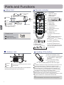 4
4
-
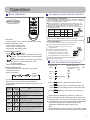 5
5
-
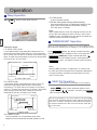 6
6
-
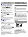 7
7
-
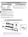 8
8
-
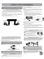 9
9
-
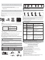 10
10
-
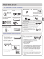 11
11
-
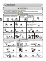 12
12
-
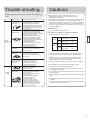 13
13
-
 14
14
-
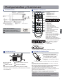 15
15
-
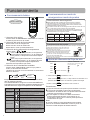 16
16
-
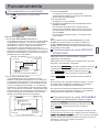 17
17
-
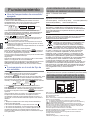 18
18
-
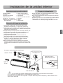 19
19
-
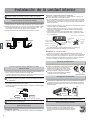 20
20
-
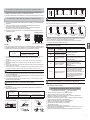 21
21
-
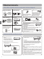 22
22
-
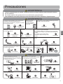 23
23
-
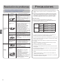 24
24
-
 25
25
-
 26
26
-
 27
27
-
 28
28


Aspes AAS3012B Manual de usuario
- Tipo
- Manual de usuario
En otros idiomas
- English: Aspes AAS3012B User manual
Documentos relacionados
Otros documentos
-
Haier AS07GS1ERA Instrucciones de operación
-
Haier AS07GS2ERA - Instrucciones de operación
-
-
-
Haier AS24GS1ERA El manual del propietario
-
-
Haier AS07NS3HRA Operation Manual And Installation Manual
-
-
-