Greenworks Pro ST80L210 Instrucciones de operación
- Categoría
- Podadoras de césped
- Tipo
- Instrucciones de operación

80V 16” Cordless String Trimmer
Read all safety rules and instructions carefully before operating this tool.
Owner’s Manual
TOLL-FREE HELPLINE: 1-855-345-3934
www.greenworkstools.com/80v-pro
ST80L00

2
CONTENTS
Contents .............................................................................................................................. 2
Product Specications ........................................................................................................ 2
Important Safety Instructions ............................................................................................... 3
Symbols ............................................................................................................................... 5
Know Your String Trimmer ................................................................................................... 7
Assembly ............................................................................................................................. 9
Operation ........................................................................................................................... 15
Battery & Charger Maintenance................................................ .......................................... 23
Maintenance........................................................................................................................... 25
Environmentally Safe Battery Disposal .................................................................................26
Troubleshooting..................................................................................................................27
Limited Warranty................................................................................................................29
Exploded View and Part List .................................. ..............................................................30
PRODUCT SPECIFICATIONS
80V 16" CORDLESS STRING TRIMMER
Type ............................................................................................. Cordless, battery powered
Motor .............................................................................................................. 80V Brushless
Cutting Width ...........................................................................14 in. /16 in. (35.6 cm / 40.6 cm)
Line Diameter ..................................................................................Nylon / 0.080" (2 mm)
Speed ...........................................................................................................6200 (±10%)RPM
Feed Type ...............................................................................................................Bump Feed
Weight (without battery) ...............................................................................7.1 lbs (3.2 kg)

3
IMPORTANT SAFETY INSTRUCTIONS
WARNING
Read and understand all instructions before using this product. Failure to follow all
instructions listed below may result in electric shock, re, and/or serious personal injury.
• Use only identical manufacturer’s replacement parts and accessories. Use of any other parts
may create a hazard or cause product damage.
• Always wear safety glasses with side shields marked to comply with ANSI Z87.1. Everyday
glasses have only impact resistant lenses. They are NOT safety glasses. Following this rule
will reduce the risk of eye injury. Use face mask if operating in dusty work spaces.
• Avoid Dangerous Environment — Don’t expose power tools to damp or wet conditions. Water
entering a power tool will increase the risk of electric shock.
• Don’t use in rain.
• Keep all bystanders, children, and pets at least 50 ft. away.
• Do not use the power tools for any job except that for which it is intended.
• Avoid Unintentional Starting – Do not carry string trimmer with ngers on the switch. Be sure
the battery is removed while transporting.
• Do not operate the equipment while barefoot or when wearing sandals or similar lightweight
footwear. Wear protective footwear that will protect your feet and improve your footing on
slippery surfaces.
• Don’t overreach - Keep proper footing and balance at all times.
• Stay alert - Watch what you are doing. Use common sense. Do not operate this unit when you
are tired, ill or under the inuence of alcohol, drugs or medication.
• Always store idle power tools indoors - When not in use, power tools should be stored indoors
in a dry place, out of reach of children.
• Power tool maintenance – Replace string head if cracked, chipped, or damaged in any
way. Be sure the string head is properly installed and securely fastened. Keep cutting edge
sharp and clean for best performance and to reduce the risk of injury. Follow instructions for
lubricating and changing accessories. Inspect appliance cord periodically, and if damaged,
have it repaired by an authorized service facility. Inspect extension cords periodically and
replace if damaged. Keep handles dry, clean, and free from oil and grease. Failure to do so
can cause serious injury.
• Check Damaged Parts – Before further use of the appliance, a guard or other part that is
damaged should be carefully checked to determine that it will operate properly and perform its
intended function. Check for alignment of moving parts, binding of moving parts, breakage of
parts, damaged mountings, and any other condition that may affect its operation. A guard or
other part that is damaged should be properly repaired or replaced by an authorized service
center unless indicated elsewhere in this manual.
• Do not charge or operate cordless tools in damp or wet locations or in the rain. Following this
rule will reduce the risk of electric shock.
• Remove or disconnect battery before servicing, cleaning or removing material from the
gardening appliance.

4
IMPORTANT SAFETY INSTRUCTIONS
• Do not dispose of the batteries in a re. The cells may explode. Check with local codes for
possible special disposal instructions.
• Do not open or mutilate the batteries. Released electrolyte is corrosive and may cause
damage to the eyes or skin. It may be toxic if swallowed.
• Exercise care in handling batteries in order not to short the battery with conducting materials
such as rings, bracelets, and keys. The battery or conductor may overheat and cause burns.
• Dress Properly – Do not wear loose clothing or jewelry. They can be caught in moving parts.
Use of rubber gloves and substantial footwear is recommended when working outdoors. Wear
protective hair covering to contain long hair.
• Do not add unnecessary force to your power tool – It will do the job better and with less
likelihood of a risk of injury at the rate for which it was designed.
• Recharge only with the charger specied by the manufacturer. A charger that is suitable for
one type of battery pack may create a risk of re when used with another battery pack.
• For use only with (2901302, 2902402) battery. For use only with (2901402, 2903702) charger.
• When battery pack is not in use, keep it away from other metal objects, like paper clips, coins,
keys, nails, screws or other small metal objects, that can make a connection from one terminal
to another. Shorting the battery terminals together may cause a re.
• Under abusive conditions, liquid may be ejected from the battery; avoid contact. If contact
accidentally occurs, ush with water. If liquid contacts eyes, additionally seek medical help.
Liquid ejected from the battery may cause irritation or burns.
• Do not use a battery pack or appliance that is damaged or modied. Damaged or modied
batteries may exhibit unpredictable behavior resulting in re, explosion or risk of injury.
• Do not expose a battery pack or power tools to re or excessive temperature. Exposure to re
or temperature above 265°F (130°C) may cause explosion.
W A R N I N G (PROPOSITION 65)
Some dust created by power sanding, sawing, grinding, drilling, and other construction activities
contains chemicals known to cause cancer, birth defects or other reproductive harm. Some
examples of these chemicals are:
• Lead from lead-based paints
• Crystalline silica from bricks and cement and other masonry products, and
• Arsenic and chromium from chemically treated lumber.
Your risk of exposure to these chemicals varies depending on how often you do this type of
work. To reduce your exposure to these chemicals, work in a well-ventilated area, and work with
approved safety equipment, such as dust masks that are specially designed to lter out microscopic
particles.
SAVE THESE INSTRUCTIONS

5
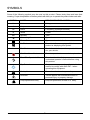
Some of the following symbols may be used on this product. Please study them and learn their
meaning. Proper interpretation of these symbols will allow you to operate the product better and safer.
SYMBOL NAME DESIGNATION/EXPLANATION
V Volts Voltage
A Amperes Current
Hz Hertz Frequency (cycles per second)
W Watts Power
min Minutes Time
Alternating Current Type of current
Direct Current Type or a characteristic of current
No Blade Do not install or use any type of blade on a
product or displaying this symbol.
/min Per Minute Revolutions, strokes, surface speed, orbits
etc., per minute.
Wet Conditions Alert Do not expose to rain or use in damp locations.
Read The Operator’s Manual To reduce the risk of injury user must read and
understand operator’s manual before using
this product.
Eye Protection Always wear eye protection with side shields
marked to comply with ANSI Z87.1 when
operating this equipment.
Safety Alert Precautions that involve your safety.
Ricochet Thrown objects can ricochet and result in
personal injury or property damage.
Keep Bystanders Away Keep all bystanders at least 50 ft. away.
SYMBOLS

The following signal words and meanings are intended to explain the levels of risk associated
with this product.
SERVICE
Servicing requires extreme care and knowledge and should be performed only by a qualified
service technician. For service we suggest you return the product to your nearest AUTHORIZED
SERVICE CENTER for repair. Use only identical manufacturer’s replacement parts and
accessories.
WARNING
To avoid serious personal injury, do not attempt to use this product until you have read this Owner's
Manual thoroughly and understand it completely. If you do not understand the warnings and
instructions in this Owner's Manual, do not use this product. Call the Toll-free Helpline (1-855-345-
3934) for assistance. The operation of any power tool can result in foreign objects being thrown
into your eyes, which can result in severe eye damage. Before operating a power tool, always wear
safety goggles, safety glasses with side shields, or a full face shield when needed. We recommend
a Wide Vision Safety Mask for use over eyeglasses or standard safety glasses with side shields.
Always use eye protection that is marked to comply with ANSI Z87.1.
WARNING
The operation of any power tool can result in foreign objects being thrown into your eyes,
which can result in severe eye damage. Before beginning power tool operation, always
wear safety goggles or safety glasses with side shields and, when needed, a full face
shield. We recommend Wide Vision Safety Mask for use over eyeglasses or standard
safety glasses with side shields. Always use eye protection which is marked to comply
with ANSI Z87.1.
DANGER Indicates an imminently hazardous situation, which, if not
avoided, will result in death or serious injury.
WARNING Indicates a potentially hazardous situation, which, if not avoided,
could result in death or serious injury.
CAUTION Indicates a potentially hazardous situation, which, if not avoided,
may result in minor or moderate injury.
CAUTION (Without Safety Alert Symbol) Indicates a situation that may
result in property damage.
SYMBOLS
SAVE THESE INSTRUCTIONS
6
SYMBOL SIGNAL MEANING

7
KNOW YOUR STRING TRIMMER
Fig. 1
3
4
5
6
1
2
8
7

8
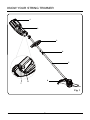
KNOW YOUR STRING TRIMMER (See Figure 1.)
The safe use of this product requires an understanding of the information on the product and in
this operator’s manual as well as a knowledge of the project you are attempting. Before use of this
product, familiarize yourself with all operating features and safety rules.
1. BATTERY PACK LATCH
Press to release the battery pack from the tool.
2. REAR HANDLE
Ergonomic handle with overmold improves comfort and grip.
3. AUXILIARY HANDLE
The string trimmer is equipped with an auxiliary handle for ease of operation and to prevent loss
of control.
4. COUPLER
The coupler connects and locks the two shafts.
5. TRIMMER SHAFT
The trimmer shaft encloses and protects the cables between the motor and rear handle.
6. GUARD
The trimmer includes a guard that helps protect from ying debris.
7. LOCK-OUT BUTTON
The lock-out button prevents accidental starting.
8. SWITCH TRIGGER
To turn the string trimmer On and Off.
KNOW YOUR STRING TRIMMER

9
ASSEMBLY
WARNING
Do not use this product if any parts on the packing list are already assembled to your product when
you unpack it. Parts on this list are not assembled to the product by the manufacturer and require
customer installation. Use of a product that may have been improperly assembled could result in
serious personal injury.
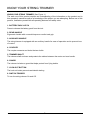
PACKING LIST
Part Name Figure Qty
String trimmer
1
Auxiliary handle
1
Guard
1
Edge guide
1
Operator's manual
40V Brushed String Trimmer
Read all safety rules and instructions carefully before operating this tool.
Owner’s Manual
TOLL-FREE HELPLINE: 1-888-90WORKS (888.909.6757)
www.GreenWorksTools.com
2101602
1
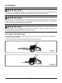
UNPACKING
This product requires assembly.
• Carefully remove the product and any accessories from the box. Make sure that all items
listed in the packing list are included.
• Inspect the tool carefully to make sure no breakage or damage occurred during shipping.
• Do not discard the packing material until you have carefully inspected and satisfactorily
operated the tool.
• If any parts are damaged or missing, please call 1-855-345-3934.

ASSEMBLY
10
WARNING
If any parts are damaged or missing, do not operate this product until the parts are replaced. Use
of this product with damaged or missing parts could result in serious personal injury.
WARNING
Do not attempt to modify this product or create accessories not recommended for use with this
string trimmer. Any such alteration or modification is misuse and could result in a hazardous
condition leading to possible serious personal injury.
WARNING
Do not connect to power supply until assembly is complete. Failure to comply could result in
accidental starting and possible serious personal injury.
ATTACHING THE EDGE GUIDE
The edge guide can limit the cutting range of the cutting line and reduce the risk of the rotating
cutting line causing damage.
To use the edge guide, press the edge guide onto the trimmer head.
Fig. 2.1
Fig. 2.2

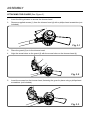
ATTACHING THE GUARD (See Figure 3.)
NOTE: Install the guard before the attachment is connected to the lower shaft.
1. Invert the string trimmer to access the trimmer head.
2. Remove supplied screws (1) from the trimmer head (4) with a philips head screwdriver (not
included).
Fig. 3.1
1
3. Place the guard (2) on to the trimmer head.
4. Align the screw holes on the guard (3) with the screw holes on the trimmer head (4)
Fig. 3.2
2
3
4
5. Insert the screws into the trimmer head, fastening the guard in place using a philips head
screwdriver (not included).
Fig. 3.3
ASSEMBLY

ASSEMBLY
12
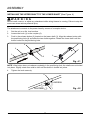
INSTALLING THE UPPER SHAFT TO THE LOWER SHAFT (See Figure 4.)
WARNING
Never install, remove, or adjust any attachment while string trimmer is running. Failure to stop the
motor can cause serious personal injury.
The attachment connects to the power head by means of a coupler device.
1. Set the unit on a at, level surface.
2. Loosen the knob (1) on the coupler (5).
3. Push in the release button (2) located on the lower shaft (3). Align the release button with
the positioning hole (4) and slide the two shafts together. Rotate the lower shaft until the
button locks into the positioning hole.
4
2
3
1
5
Fig. 4.1
2
NOTE: If the button does not release completely in the positioning hole, the shafts are not locked
into place. Slightly rotate from side to side until the button is locked into place.
4. Tighten the knob securely.
Fig. 4.2
LOOSE
N
5
TIGHTEN
1

ASSEMBLY
13
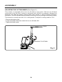
ATTACHING THE AUXILIARY HANDLE (See Figure 5.)
1. Loosen the four screws (1) in the handle with a philips screwdriver (not included) and
remove the screws from the handle.
Fig. 5.1
1
2. Attach the auxiliary handle (2) and lower clamp (3) on the shaft.
3. Adjust handle up or down, if necessary, to desired operating position.
Fig. 5.2
4. Tighten the four screws so that the handle cannot be rotated on the shaft.
Fig. 5.3

ADJUSTING THE CUTTING SWATH (See Figure 6.)
This trimmer is equipped with a line cut-off blade on the guard. The line cut off blade
continuously trims the line to ensure a consistent and efficient cut diameter. Advance line
whenever you hear the engine running faster than normal, or when trimming efficiency
diminishes. This will maintain best performance and keep line long enough to advance properly.
This trimmer is currently set at the 14 in. cutting swath. To adjust to a cutting swath of 16 in.:
• Remove the battery pack.
• Loosen the blade screw then rotate the line cut-off blade 180°.
• Tighten the blade screw.
Screw
Cut-off blade
Fig. 6
ASSEMBLY
14

15
OPERATION
WARNING
Read and understand entire Operator's Manual for each optional attachment used on this power
head and follow all warnings and instructions. Failure to follow all instructions may result in electric
shock, re and/or serious personal injury.
WARNING
Do not allow familiarity with this product to make you careless. Remember that a careless fraction
of a second is sufcient to inict serious injury.
WARNING
Do not use any attachments or accessories not recommended by the manufacturer of this product.
The use of attachments or accessories not recommended can result in serious personal injury.
WARNING
This string trimmer is not meant to be used with brush cutter attachments. Use of a brush cutter
attachment could cause serious personal injuries or property damage.

16
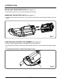
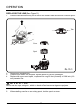
INSTALLING THE BATTERY PACK (See Figure 7.)
• Insert battery pack into tool until an audible click is heard.
REMOVING THE BATTERY PACK (See Figure 7.)
• Depress the battery release button (1) in the back of the battery pack and pull battery pack out
of tool.
1
STARTING AND STOPPING THE TRIMMER (See Figure 8.)
• Ensure a fully charged battery is installed into the string trimmer.
• To start the string trimmer, press and hold the safety lock button (1) and squeeze the switch trigger
(2).
• To stop the string trimmer, release switch trigger to stop.
1
2
Fig. 8
OPERATION
Fig. 7

17
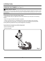
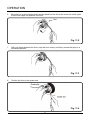
OPERATING THE TRIMMER (See Figure 9.)
WARNING
Always hold the string trimmer away from the body keeping clearance between the body and the
string trimmer. Any contact with the string trimmer cutting head while operating can result in serious
personal injury.
Follow these tips when using the string trimmer:
• Hold the trimmer with your right hand on the reat handle and your left hand on the auxiliary
handle.
• Keep a rm grip with both hands while in operation.
• Trimmer should be held at a comfortable position with the rear handle about hip height.
• Cut tall grass from the top down. This will prevent grass from wrapping around the shaft
housing and string head which may cause damage from overhearing.
If grass becomes wrapped around the string head:
• Remove the battery pack.
• Remove the grass.
Fig. 9
OPERATION

18
OPERATION
WARNING
Any contact with the attachment cutting head can result in burns and/or other serious personal
injury.
WARNING
Read the safety information for safe operation when using a blade attachment and refer to the
safety rules and instructions in your attachment manual. Never use a brush cutter attachment with
this electric power head. Improper operation of a blade or any attachment could result in serious
injury.
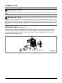
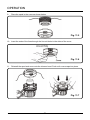
ADVANCING LINE (See Figure 10.)
While the string trimmer is operating, the cutting line gets worn down and becomes shorter.
This trimmer is equipped with bump feed line advancement, which advances additional line
once the head is bumped on the ground while rotating. The cutting blade will cut the line to
keep an accurate cutting swath.
Bump knob
Fig. 10

19
OPERATION
REPLACING THE LINE (See Figure 11.)
1. Press the tabs simultaneously on the side of the trimmer head and remove cover and spool.
Cover
Spool
Fig. 11.1
Tab
2. Remove any remaining line.
3. Clean dirt and debris from all parts. Replace spool if it is worn or damaged.
4. Replace with a pre-wound spool, or replace line using 25 feet (8 meters) of 0.080 inch (2.0
mm) diameter line.
WARNING
Never use wire, rope, string, etc., which can break off and become a dangerous projectile.
5. When installing new line on an existing spool, hold the spool as shown.

20
OPERATION
6. Bend the line at the midpoint and insert the bend into the slot in the center rim of the spool.
Ensure line snaps into position in the slot
.
Slot
Fig. 11.2
7. With your nger between the lines, wrap the lines evenly and rmly around the spool in a
clockwise direction.
Fig. 11.3
8. Position the lines in the guide slots.
Fig. 11.4

21
OPERATION
9. Place the spool in the cover as shown below.
Fig. 11.5
10. Insert the ends of the lines through the line exit holes in the sides of the cover.
Fig. 11.6
11. Reinstall the spool and cover onto the trimmer head. Push until cover snaps into place.
Fig. 11.7

22
OPERATION
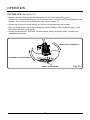
CUTTING TIPS (See Figure 12.)
• Keep the trimmer tilted toward the area being cut; this is the best cutting area.
• The trimmer cuts when passing the unit from right to left. This will avoid throwing debris at the
operator. Avoid cutting in the dangerous area shown in gure 12.
• Use the tip of string to do the cutting; do not force string head into uncut grass.
• Wire and picket fences cause extra string wear and breakage. Stone and brick walls, curbs,
and wood may wear string rapidly.
• Avoid trees and shrubs. Tree bark, wood moldings, siding, and fence posts can easily be
damaged by the string.
DANGEROUS CUTTING AREA
BEST CUTTING AREA
DIRECTION OF ROTATION
Fig. 12

23
BATTERY & CHARGER MAINTENANCE
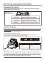
CHECKING BATTERY CAPACITY
Press the battery capacity indicator (BCI) button. The lights will illuminate according to the
batteries capacity level. See chart below:
BATTERY CAPACITY
INDICATOR (BCI) BUTTON
LIGHT METER
Lights
Capacity
The battery is more than 75% capacity
3 Green Lights
The battery is between 35% and 75% capacity 2 Green Lights
The battery is less than 35% capacity
1 Green Light
Lights go out
The battery requires charging immediately
CHARGING PROCEDURE
NOTE: The battery is not shipped fully charged. It is recommended to fully charge before rst use to ensure
that maximum run time can be achieved. This lithium-ion battery will not develop a memory and may be
charged at any time.
1. Plug the charger into an AC power outlet.
2. Insert the battery pack into the charger.
This is a diagnostic charger. The Charger LED Lights will illuminate in specic order to
communicate the current battery status. They are as follows:
Charging Fully
Charged
Over
Temperature
Charging
Fault
LED STATUS DESCRIPTION
Blinking Gree harging
Solid Green Fully Charged
Solid Red Over Temperature
Blinking Re harging Fault
n
C
C
d
False Defect Note: When the battery is inserted into the charger, and the status LED ashes,
remove the battery from the charger for 1 minute, then reinsert. If the status LED indicates
normal than the battery pack is good. If the status LED is still blinking, remove the battery pack
and unplug the charger. Wait 1 minute and plug the charger back in and reinsert the battery
pack. If the status LED indicates normal than the battery pack is good. If the status LED is still
blinking then the battery pack is defective and needs to be replaced.

24
BATTERY & CHARGER MAINTENANCE
CHECKING THE CHARGE
If the battery pack does not charge properly:
• Check the current at the power outlet with another tool. Make sure that the outlet is not turned
off.
• Check that the charger contacts have not been shorted by debris or foreign material.
• If the surrounding air temperature is not normal room temperature, move the charger and
battery pack to a location where the temperature is between 45 ˚F and 104˚F .
WARNING
If the battery is inserted into the charger when warm or hot, the CHARGING LED indicator light on
the charger may switch on and illuminate RED. If this occurs allow the battery to cool outside of
the charger from approximately 30 minutes. Charging should automatically start once battery has
cooled.
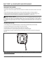
CHARGER MOUNTING
1. This charger can be installed hanging on a wall using two #8 screws (not included).
2. Locate the placement for the charger to be wall mounted.
3. If fastening to wood studs use 2 wood screws (not included).
4. Drill two holes 4.5 in. apart ensuring that they are vertically aligned.
5. If fastening to drywall use wall anchors (not included) and screws to secure the charger to
the wall.
NOTE: If the battery and the charger won’t be used for a long time, please remove the battery from the charger
and pull out the AC power plug.

25
GENERAL MAINTENANCE
Avoid using solvents when cleaning plastic parts. Most plastics are susceptible to damage from
various types of commercial solvents and may be damaged by their use. Use clean cloths to
remove dirt, dust, lubricant, grease, etc.
Always store the machine clean and in a dry enclosure with the battery charged.
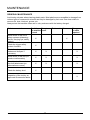
MAINTENANCE
Maintenance task Each time
the machine
is used
Every two
hours
Each week After use Every year
or when
required
Visual check of the tool's
safety systems (distancing
device, carrying eye, safety
casing)
X X
Check the trigger safety
system functions
X
Check the sharpness of
blades and sharpen if
necessary
X X X
Visual check of the tool (no
cracks or deformation)
X X X
Visual check of the tool at
the shaft attachment (no
deformations or wear)
X X X
Check the battery level X
Inspection of the tool by an
approved Greenworks dealer
X

26
ENVIRONMENTALLY SAFE BATTERY DISPOSAL
The following toxic and corrosive materials are in the batteries used in this string trimmer battery
pack: Lithium-Ion, a toxic material.
WARNING
All toxic materials must be disposed of in a specified manner to prevent contamination of the
environment. Before disposing of damaged or worn out Lithium-Ion battery packs, contact your
local waste disposal agency, or the local Environmental Protection Agency for information and
specific instructions. Take the batteries to a local recycling and/or disposal centre, certified for
lithium-ion disposal.
WARNING
If the battery pack cracks or breaks, with or without leaks, do not recharge it and do not use.
Dispose of it and replace with a new battery pack. DO NOT ATTEMPT TO REPAIR IT!
To avoid injury and risk of re, explosion, or electric shock, and to avoid damage to the
environment:
• Cover the battery's terminals with heavy-duty adhesive tape.
• DO NOT attempt to remove or destroy any of the battery pack components.
• DO NOT attempt to open the battery pack.
• If a leak develops, the released electrolytes are corrosive and toxic. DO NOT get the
solution in the eyes or on skin, and do not swallow it.
• DO NOT place these batteries in your regular household trash.
• DO NOT incinerate.
• DO NOT place them where they will become part of any waste landll or municipal solid
waste stream.
• Take them to a certied recycling or disposal centre.

27
TROUBLESHOOTING
Problem Cause Solution
String trimmer
fails to start
when trigger
lock button is
depressed.
1. The battery pack is not
attached to the trimmer.
1. Attach the battery pack to the trimmer.
2. No electrical contact
between the trimmer and
battery.
2. Remove battery check contact and reinstall
the battery pack.
3. The battery pack is depleted. 3. Charge the battery pack.
4. The lock-off lever and
trigger are not depressed
simultaneously.
4. Press down the lock-off lever and hold it
,
then depress the trigger to turn on the string
trimmer.
5. Did not press the power
button, press the trigger
directly.
5. Start the power button, the power indicator
will trigger later.
String trimmer
stops while
cutting.
1. The guard is not mounted
on the trimmer
,
resulting in an
overly long cutting and motor
overload.
1. Remove the battery pack and mount the
guard on the trimmer.
2. Heavy cutting line is used
.
2. Use only with nylon cutting line 0.08"
diameter or less.
3. The motor shaft or trimmer
head is bound with grass.
3. Stop the trimmer
,
remove the battery
,
and
remove the grass from the motor shaft and
trimmer head.
4. The motor is overloaded. 4. Remove the trimmer head from the grass.
the motor will recover to work as soon as
the load is removed. when cutting
,
move the
trimmer head in and out of the grass to be cut
and remove no more than 8 inches of length
in a single cut.
5. The battery pack or string
trimmer is too hot.
5. Allow the battery pack to cool until the
temperature drops below 158°F
(
70°C
).
Allow the trimmer to cool until the temperature
drops below 284°F (140°C).
6. The battery pack is
disconnected from the tool
.
6. Re-install the battery pack.
7. The battery pack is depleted. 7. Charge the battery pack.

28
TROUBLESHOOTING
Problem Cause Solution
Lines will not
advance.
1. Lines are welded to
themselves.
1. Lubricate with silicone spray.
2. Not enough line on
spool.
2. Install more line. Refer to Line
Replacement earlier in this manual.
3. Lines are worn too short
.
3. Pull both lines while pressing button.
4. Lines are tangled on
spool
.
4. Remove lines from spool and rewind.
Refer to Line Replacement earlier in
this manual.
Line keeps
breaking.
1. Trimmer used incorrectly. 1. Only trim with the tip of the line
,
avoid
stones
,
walls and other hard objects. Feed the
line regularly to maintain full cutting width.
Grass wraps
around trimmer
head and motor
housing.
1. Cutting tall grass at ground
level
1. Cut tall grass from the top down
,
removing
no more than 8 inches in each pass to prevent
wrapping.
Line is not
cutting well
1. The line-cutting blade on the
edge of the guard has become
dull
.
1. Sharpen the line-cutting blade with a le or
replace it with a new blade.

29
LIMITED WARRANTY
GREENWORKS™ hereby warranties this product, to the original purchaser with proof
of purchase, 4 year warranty against defects in materials, parts or workmanship.
GREENWORKS™, at its own discretion will repair or replace any and all parts found to be
defective, through normal use, free of charge to the customer. This warranty is valid only for
units which have been used for personal use that have not been hired or rented for industrial/
commercial use, and that have been maintained in accordance with the instructions in the
owners’ manual supplied with the product from new.
ITEMS NOT COVERED BY WARRANTY:
1. Any part that has become inoperative due to misuse, abuse, neglect, accident, improper
maintenance, or alteration; or
2. The unit, if it has not been operated and/or maintained in accordance with the owner's
manual; or
3. Normal wear, except as noted below;
4. Routine maintenance items such as lubricants, blade sharpening;
5. Normal deterioration of the exterior nish due to use or exposure.
GREENWORKS HELPLINE (1-855-345-3934):
Warranty service is available by calling our toll-free helpline at (1-855-345-3934).
TRANSPORTATION CHARGES:
Transportation charges for the movement of any power equipment unit or attachment are the
responsibility of the purchaser. It is the purchaser’s responsibility to pay transportation charges
for any part submitted for replacement under this warranty unless such return is requested in
writing by GREENWORKS.

30
EXPLODED VIEW
1
2
45 3
12
14
15
13
6
7
8
9
11
10

31
PARTS LIST
Item No. Part No. Description QTY
1 34107511-10 Knob 1
2 311121416 Bare tool assembly 1
3 33208334 Screw 4
4 34130334 Auxiliary handle 1
5 34140334 Plate 1
6 333041429 Edge guide 1
7 332041428 Spring 1
8 341041429AB Bump head 1
9 311101429 Spool 1
10 311091429 Spool cover 1
11 322011429 Washer 2
12 32207319 Screw 2
13 32916131 Spring washer 2
14 333011429 Cut-off blade 1
15 341081429AB Guard 1

TOLL-FREE HELPLINE: 1-855-345-3934
Rev: 00 (11-25-15)
Greenworks Tools
PO Box 1238
Mooresville, NC 28115

Desbrozadora inalámbrica 80V 16”
Leer todas las normas de seguridad y las instrucciones cuidadosamente
antes de utilizar esta herramienta.
Manual Del Propietario
LÍNEA GRATUITA LÍNEA DE AYUDA: 1-855-345-3934
www.greenworkstools.com/80v-pro
ST80L00

2
CONTENIDOS
Contenidos........................................................................................................................... 2
Especicaciones ................................................................................................................. 2
Reglas generales de seguridad ........................................................................................... 3
Símbolos .............................................................................................................................. 5
Sepa su producto ................................................................................................................. 7
Armado ................................................................................................................................ 9
Funcionamiento ................................................................................................................. 15
Mantenimiento de la batería y el cargador................................................ ........................... 23
Mantenemento..................................................................................................................... 25
Eliminación de baterías sin daño para el ambiente ..............................................................26
Solución de problemas.....................................................................................................27
Garantía Limitada...................................................................................................................29
Plano de despiece/Lista de piezas................................................................................30
ESPECIFICACIONES
DESBROZADORA INALÁMBRICA 80V 16”
Tipo .................................................................................. Inalámbrica, activada por baterías
Motor .........................................................................................................80V sin escobillas
Diámetro de línea ....................................................................14 in. /16 in. (35.6 cm / 40.6 cm)
Área de corte ..................................................................................Nylon / 0.080" (2 mm)
Velocidad ......................................................................................................6200 (±10%)RPM
Tipo de alimentación ........................................................Alimentación mediante golpes leves
Peso (sin batería) ...............................................................................7.1 lbs (3.2 kg)

3
REGLAS GENE RALES DE SE GURIDAD
ADVERTENCIA
Lea y comprenda todas las instrucciones antes de usar este producto. Si no sigue todas las
instrucciones enumeradas a continuación, podrían producirse descargas eléctricas, incendios y/o
daños personales graves.
• Revise el área de trabajo cada vez antes del uso. Quite todo objeto inadecuado tal como rocas,
fragmentos de vidrio, clavos, alambre o cuerdas que pudieran saltar o enrollarse en la máquina.
• Use siempre gafas de seguridad con protecciones laterales. Las gafas para uso diario tienen
lentes solamente resistentes a impactos. NO son gafas de seguridad. Observar esta regla
reduce el riesgo de lesiones en los ojos. Utilice una careta si la operación produce polvo.
• Evite los entornos de trabajo peligrosos - No exponga las aparato or herramienta eléctricas a
la lluvia ni a condiciones de humedad. La introducción de agua en una herramienta eléctrica
aumenta el riesgo de descargas eléctricas.
• No lo use en la lluvia.
• Mantenga a los espectadores, niños y mascotas alejados por lo menos 15 metros (50 pies).
• No use el producto para ningún otro trabajo que no sea para el cual fue creado.
• Para prevenir encendidos accidentales, nunca cargue un producto a batería con su dedo enel
interruptor. Asegúrese de que el interruptor esté apagado cuando inserte la batería.
• No haga funcionar el equipo estando descalzo ni al usar sandalias o calzado ligero similar.
Use calzado protector que resguarde sus pies y aumente su tracción en supercies lisas.
• No realice sobreesfuerzos. Mantenga un equilibro adecuado en todo momento.
• Permanezca alerta - Preste atención a lo que está haciendo. Use el sentido común. No use
esta unidad cuando se encuentre fatigado, enfermo o bajo los efectos del alcohol, drogas o
medicamentos.
• Almacene los aparatos inactivos - Al no usar el recortador se le debe almacenar bajo techoen
un lugar seco, con llave, fuera del alcance de los niños.
• Proporcione mantenimiento con cuidado al aparato - Cambie el cabezal del hilo, si está
agrietado, desportillado o dañado de cualquier forma. Asegúrese de que el cabezal del
hilo, o cuchilla, según sea el caso, esté debidamente instalado y firmemente asegurado.
Mantenga los bordes cortantes afilados y limpias para un mejor rendimiento y reducir el
riesgo de lesiones. Siga las instrucciones de lubricación y cambio de accesorios. Inspeccione
periódicamente los cables y si están dañados llévelos a un centro de servicio autorizado.
Revise las prolongaciones periódicamente y sustitúyalas si están dañadas. La inobservancia
de esta advertencia puede causar lesiones corporales serias.
• Asegúrese de que no hayan partes dañadas. Antes de usar el producto, un protector u otra
parte que esté dañada debe ser revisada cuidadosamente para determinar si funcionará
apropiadamente y desempeñará la función para la cual fue diseñada. Verique la alineación
de las piezas en movimiento, la unión de las piezas en movimiento, el daño de piezas, el
montaje y cualquier otra condición que pueda afectar su funcionamiento. Un protector u otra
pieza que esté dañada debe ser reparado apropiadamente o reemplazado por un centro de
servicio autorizado a menos que se indique otro lugar en este manual.
• No cargue la herramienta de batería en la lluvia o en un lugar húmedo o mojado. Si sigue
estas indicaciones reducirá el riesgo de descargas eléctricas.
• Quite o desconecte la batería antes del mantenimiento, limpieza o retirada de material

4
REGLAS GENE RALES DE SE GURIDAD
delequipo para jardin.
• No deseche las baterías tirándolas al fuego. Las celdas podrían explotar. Verifique los
códigos locales para averiguar si hay instrucciones especiales para su desecho.
• No abra las baterías ni las corte. El electrolito suelto es corrosivo y podría causar lesiones en
los ojos o la piel. Podría ser tóxico si se le ingiere.
• Tenga mucho cuidado al manejar baterías para no poner en corto la batería mediante
materiales conductores tales como anillos, brazaletes y llaves. La batería o el material
conductor se podría sobrecalentar y provocar quemaduras.
• Vístase adecuadamente – No use ropa holgada o joyas. Podrían quedar atrapados en las
piezas móviles. Se recomienda el uso de guantes de goma y calzado sólido cuando se
trabaje al aire libre. Use un protector que cubra el cabello para agarrarlo.
• No fuerce la herramienta – El uso de la herramienta adecuada a la velocidad para la que está
diseñada, efectuará el trabajo de mejor y más segura manera.
• Recargue la batería solamente con el cargador especicado por el fabricante. Podría haber un
riesgo de incendio cuando se utilice un cargador con una batería para la que no está diseñado.
• Utilizar solo con baterías (2901302, 2902402). Utilizar solo con el cargador (2901402,
2903702).
• Cuando la batería no está en uso, manténgala alejada de otros objetos metálicos como clips,
monedas, llaves, clavos, tornillos u otros objetos metálicos pequeños que puedan crear una
conexión desde una terminal a otra. Si se produjese un cortocircuito en los terminales de la
batería, éste podría causar quemaduras o un incendio.
• En condiciones abusivas, podría salir expulsado líquido de la batería, por lo que debería
evitar el contacto con éste. Si se produce un contacto accidental, enjuáguese las manos con
agua. Si el líquido entra en contacto con los ojos, acuda inmediatamente al médico. Si el
líquido es expulsado de la batería podría causar irritación o quemaduras.
• No utilice una batería o apartado dañado o modicado. Las baterías dañadas o modicadas pueden
comportarse de modo imprevisto que puede causar incendio, explosión o riesgo de lesión.
• No exponga ni las baterías ni el aparato al fuego ni a altas temperaturas. La exposición al
fuego o a temperaturas superiores a 130 ºC puede provocar explosiones. La temperatura de
130 ºC equivale a 265 ºF.
A D V E R T E N C I A (PROPOSITION 65)
El polvo creado al lijar, cortar, moler, perforar y otras actividades de construcción
contienesustancias químicas que causan cáncer, defectos de nacimiento u otros daños
reproductivos.Algunos ejemplos de estos productos químicos son:
• El plomo de las pinturas a base de plomo
• La sílice cristalina de ladrillos y cemento y otros productos de albañilería, y
• El arsénico y el cromo de la madera tratada químicamente.
El riesgo de exposición a estos químicos varía en función de la frecuencia con que realiza este
tipo de trabajo. Para reducir su exposición a estas sustancias químicas, trabaje en un área bien
ventilada y con equipos de seguridad aprobados, como mascarillas contra el polvo especialmente
diseñadas para ltrar partículas microscópicas.
GUARDE ESTAS INSTRUCCIONES

5
SÍMBOLOS
Es posible que se empleen en este producto algunos de los siguientes símbolos. Le
suplicamosestudiarlos y aprender su significado. Una correcta interpretación de estos símbolos le
permitirá utilizar mejor y de manera más segura el producto.
SÍMBOLO NOMBRE DENOMINACIÓN/EXPLICACIÓN
V
Volts Voltaje
A
Amperios Corriente
Hz
Hertz Frecuencia (ciclos por segundo)
W
Watts Potencia
min
Minutos Tiempo
Corriente alterna Tipo de corriente
Corriente continua Tipo o característica de corriente
No instale hoja de corte No instale ni utilice ningún tipo de hoja de
corte en ningún producto con este símbolo.
/min
Por minuto Revoluciones, carreras, velocidad supercial,
órbitas, etc. por minuto.
Alerta de condiciones
húmedas
No exponga la unidad a la lluvia ni la use en l
ugares húmedos.
Lea el manual del operador Para reducir el riesgo de lesiones, el usuario
debe leer y comprender el manual del
operador antes de usar este producto.
Protección ocu lar Al utilizar este producto, póngase siempre
gafas de seguridad con protección lateral, y
en la medida en que sea necesario, utilice un
protector para toda la cara..
Alerta de se guridad Precauciones para su seguridad.
Rebote Cualquier objeto lanzado puede rebotar y
producir lesiones personales o daños físicos.
Mantenga alejadas a las
personas presentes
Mantenga a los circunstantes a una distancia
mínima de 15 m (50 pies).

SÍMBOLOS
6
Las siguientes palabras de señalización y sus signicados tienen el objeto de explicar los niveles
de riesgo relacionados con este producto.
SERVICIO
Para dar servicio es necesario tener extremo cuidado y conocimiento, el servicio debe ser
proporcionado solamente por técnicos de servicio calicados. Sugerimos que para dar servicio
al producto lo regrese a su CENTRO DE SERVICIO AUTORIZADO más cercano para que los
reparen. Al dar servicio, use solamente repuestos idénticos.
ADVERTENCIA
Para evitar lesiones personales graves, no trate de usar este producto antes de haber leído
completamente el presente Manual del Propietario y haberlo comprendido en su totalidad.
Si no comprende las advertencias y las instrucciones que aparecen en el presente Manual
del Propietario, no use el producto. Llame gratis al 1-855-345- 3934 para recibir ayuda. Toda
herramienta eléctrica al funcionar puede lanzar objetos extraños hacia sus ojos, lo que podría
provocarles lesiones graves. Antes de operar una herramienta eléctrica, use siempre gafas de
seguridad, gafas de seguridad con protecciones laterales o una careta completa si es necesario.
Recomendamos usar una careta de seguridad con rango visual ancho encima de gafas de
seguridad estándar, o usar gafas de seguridad estándar con protecciones laterales. Use siempre
protección para los ojos con viñetas que indiquen que cumplen ANSI Z87.1.
ADVERTENCIA
Toda herramienta eléctrica al funcionar puede lanzar objetos extraños hacia sus ojos,
lo que podría provocarles lesiones graves. Antes de comenzar el funcionamiento de
una herramienta eléctrica, use siempre gafas de seguridad o gafas de seguridad con
protecciones laterales y, si es necesario, una careta completa. Recomendamos usar
caretas de seguridad con rango visual ancho encima de gafas de seguridad estándar,
o usar gafas de seguridad estándar con protecciones laterales. Use siempre protección
para los ojos con viñetas que indiquen que cumplen ANSI Z87.1.which can result in
severe eye damage.
PELIGRO Indica una situación peligrosa inminente, la cual, si no se evita,
causará la muerte o lesiones serias.
ADVERTENCIA Indica una situación peligrosa posible, la cual, si no se evita,
podría causar la muerte o lesiones serias.
PRECAUCIÓN Indica una situación peligrosa posible, la cual, si no se evita,
podría causar lesiones menores o leves.
PRECAUCIÓN (Sin el símbolo de alerta de seguridad) Indica una situación que
puede producir daños materiales.
GUARDE ESTAS INSTRUCCIONES
SÍMBOLO SEÑAL SIGNIFICADO

7
SEPA SU PRODUCTO
Fig. 1
3
4
5
6
1
2
8
7

8
CONOZ CA SU PROD UCTO (Vea la gura 1.)
El uso seguro de este producto requiere la comprensión de la información del producto y del
manual de usuario, así como el conocimiento de la tarea que intenta realizar. Antes de utilizar este
producto, familiarícese con las características de funcionamiento y normas de seguridad.
1. SEGURO DE LA BATERÍA
Pulse para retirar la batería de la herramienta.
2. EMPUÑADURA TRASERA
Mango ergonómico sobremoldeado para mayor comodidad y sujeción.
3. MANGO AUXILIAR
La cabeza motriz está equipada con un conjunto de mango frontal para facilitar el uso y para
evitar la pérdida de control.
4. ANILLO DE ACOPLE
El acoplador conecta y bloquea los dos ejes.
5. RESISTENTE EJE DE LA RECORTADORA
El eje sólido de la recortadora contiene y protege los cables entre el motor y el cabezal de la
recortadora.
6. PROTECTOR
La recortadora incluye una protección que ayuda a protegerse de los fragmentos volátiles.
7. BOTÓN DE BLOQUEO
El botón de bloqueo impide el arranque accidental.
8. GATILLOINTERRUPTOR
Para encender y apagar la recortadora de hilo.
SEPA SU PRODUCTO

9
ARMADO
ADVERTENCIA
No utilice este producto si ya está montado en el producto algún elemento de la lista del paquete
de embalaje cuando lo desembale. El fabricante no ha montado los elementos de esta lista en
el producto y requieren de la instalación del cliente. Usar un producto que puede haber sido mal
montado podría provocar graves daños personales.
LISTA DE PIEZAS
Nombre de las piezas Figura Cant.
Recortadora de hilo
1
Mango auxiliar
1
Hierba deector
1
Guía de bordes
1
Manual de instrucciones
40V Brushed String Trimmer
Read all safety rules and instructions carefully before operating this tool.
Owner’s Manual
TOLL-FREE HELPLINE: 1-888-90WORKS (888.909.6757)
www.GreenWorksTools.com
2101602
1
DESEMBALAJE
Es necesario montar este producto.
• Retire con cuidado el producto y los accesorios de la caja. Asegúrese de que están incluidos
todos los elementos que guran en la lista del paquete de embalaje.
• Revise el producto con atención para asegurarse de que no se produjeron daños o roturas
durante el transporte.
• No tire el material de embalaje hasta que haya revisado con atención y haya utilizado el
producto de manera satisfactoria.
• Si falta alguna parte dañada o se encuentra dañada, llame al 1-855-345-3934 para que le
proporcionen asistencia.

ARMADO
10
ADVERTENCIA
Si falta alguna parte dañada o se encuentra dañada, no utilice el producto hasta que haya
sustituido las piezas. Usar este producto si falta alguna pieza o si alguna está dañada podría
provocar graves daños personales.
ADVERTENCIA
No intente modicar este producto o crear accesorios no recomendados para ser usados con él.
Cualquier alteración o modicación es un uso incorrecto del producto y podría provocar situaciones
peligrosas que conlleven graves daños personales.
ADVERTENCIA
No conecte la unidad al suministro de energía hasta que esté completamente montada. Si
la máquina está mal montada, podría arrancar accidentalmente y provocar graves daños
personales.
COLOCAR EL DEFLECTOR DE HIERBA
El guía de borde puede limitar el rango de corte del hilo de corte y reducir el riesgo de que el hilo
de corte giratorio cause daños.
Para usar el guía de borde, presione el guía de borde en el cabezal.
Fig. 2.1
Fig. 2.2

COLOCAR EL DEFLECTOR DE HIERBA (Vea la gura 3.)
NOTA: Instale el deector de hierba antes de conectar el accesorio a la cabeza motriz.
1. Invierta la orilladora para obtener acceso al cabezal de la orilladora.
2. Retire los tornillos (1) suministrados del cabezal de corte (4) con un destornillador de
estrella (no incluido).
Fig. 3.1
1
3. Coloque la protección (2) en el cabezal de corte.
4. Alinee los oricios de tornillos de la protección (3) con los oricios de tornillos del cabezal
de corte.
Fig. 3.2
2
3
4
5. Inserte los tornillos en el cabezal de corte, ajustando la protección en su sitio con un
destornillador de estrella (no incluido).
Fig. 3.3
ARMADO

ARMADO
12
INSTALAR EL EJE SUPERIOR EN EL EJE INFERIOR (Vea la gura 4.)
ADVERTENCIA
Nunca instale, retire o ajuste ningún accesorio mientras sigue funcionando el bloque motor. Un
fallo en la parada del motor puede causar lesiones personales graves.
El accesorio se conecta al bloque motor mediante un anillo de acople.
1. Coloque la herramienta en una supercie plana y nivelada.
2. Aoje el vástago (1) del acoplador (5).
3. Pulse el botón de liberación (2) situado en el eje inferior (3). Alinee el botón de liberación
con el oricio de posición (4) y deslice los dos ejes juntos. Gire el eje del accesorio hasta
que el botón se bloquee en al agujero de posición.
4
2
3
1
5
Fig. 4.1
2
NOTA: Si el botón no se libera por completo en el agujero de posición signica que los ejes no
están bien colocados. Gire ligeramente de un lado a otro hasta que el botón se ajuste en su
lugar.
4. Apriete la llave rmemente.
AFLOJE
5
APRIETAN
1
Fig. 4.2

ARMADO
13
FIJACIÓN DEL MANGO DELANTERO (Vea la gura 5.)
1. Aoje los cuatro tornillos (1) del mango con un destornillador de estrella (no incluido) y
retire los tornillos del mango.
Fig. 5.1
1
2. Acople el mango auxiliar (2) y baje la abrazadera (3) del eje.
3. Si es necesario, suba o baje el mango para ajustarlo a la posición de manejo deseada.
Fig. 5.2
4. Apriete los cuatro tornillos de manera que la empuñadura no pueda girar sobre el eje.
Fig. 5.3

CUCHILLA DE CORTE DEL HILO (Vea la gura 6.)
Esta recortadora está equipada con una cuchilla de corte instalada en el protección. Para
obtener mejores resultados en el recorte, avance el hilo hasta que la cuchilla lo corte a la
longitud apropiada. Avance el hilo siempre que escuche que el motor está funcionando
más rápido de lo normal, o cuando disminuya la eficiencia del recorte. Esto mantendrá un
desempeño óptimo y mantendrá el hilo a la suciente longitud para que avance correctamente.
Este recortadora de hilo es puesto actualmente en el 14 pulg. ancho de corte. Para ajustar a
una ancho de corte de 16 pulg.:
• Retire el paquete de baterías.
• Aoje el tornillo de la hoja entonces gira la hoja 180°
• Apriete el tornillo de la hoja.
Tornillo
Cuchilla de corte
Fig. 6
ARMADO
14

15
FUNCIONAMIENTO
ADVERTENCIA
Lea y comprenda el manual de usuario en su totalidad para cada accesorio opcional utilizado
en esta cabeza motriz y siga todas las advertencias e instrucciones. Si no sigue todas las
instrucciones, podrían producirse descargas eléctricas, incendios y/o daños personales graves.
ADVERTENCIA
Preste especial atención aunque esté familiarizado con el producto. Recuerde que un despiste de
una sola fracción de segundo es suciente para causar daños graves.
ADVERTENCIA
No utilice conexiones ni accesorios que no estén recomendados por el fabricante de este producto.
El uso de conexiones o accesorios no recomendados podría causar graves daños personales.
ADVERTENCIA
Esta recortadora de hilo no está diseñada para ser utilizada con accesorios de desbrozadora.
El uso de un accesorio de desbrozadora podría causar lesiones personales graves o daños
materiales.

16
INSTALACIÓN DE LA BATERÍA (Vea la gura 7.)
• Inserte la batería en la herramienta hasta que escuche un clic.
EXTRACCIÓN DE LA BATERÍA (Vea la gura 7.)
• Pulse el botón de liberación de la batería (1) en la parte trasera de la batería y retire la batería
de la herramienta.
1
ARRANCAR Y DETENER LA RECORTADORA (Vea la gura 8.)
• Compruebe que hay una batería totalmente cargada instalada en la recortadora de hilo.
• Para arrancar la recortadora, mantenga pulsado el botón de desbloqueo (1) y apriete el gatillo (2).
• Para detener la recortadora, suelte el gatillo.
1
2
Fig. 8
FUNCIONAMIENTO
Fig. 7

17
FUNCIONAMIENTO DE LA CABEZA MOTRIZ (Vea la gura 9.)
ADVERTENCIA
Siempre sujete la recortadora de hilo lejos de su cuerpo, manteniendo un espacio entre ambos.
El contacto con el cabezal de corte de la recortada de hilo durante su operación puede causar
lesiones personales graves.
Siga las siguientes recomendaciones a manejar la recortadora de hilo:
• Sujete la recortadora con la mano derecha en el mango trasero y la izquierda en el delantero.
• Sujete rmemente la unidad con ambas manos durante la operación.
• Se recomienda sujetar la recortadora en una posición cómoda, con el mango trasero a la altura
de la cadera aproximadamente.
• Corte la hierba alta desde arriba hacia abajo. Esto evitará que la hierba se enrolle alrededor
del alojamiento del eje y del cabezal del brazo, lo que puede causar daños por calentamiento
excesivo.
Si la hierba se enrolla en el cabezal del hilo:
• Desenchufe la recortadora de hilo.
• Quite la hierba.
Fig. 9
FUNCIONAMIENTO

18
FUNCIONAMIENTO
ADVERTENCIA
Cualquier contacto con el cabezal de corte del accesorio podría provocar quemaduras y/o lesiones
personales graves.
ADVERTENCIA
Lea la información de seguridad para una utilización segura cuando use un accesorio de la hoja
y consulte las normas de seguridad e instrucciones del manual de usuario. No utilice nunca un
accesorio de desbrozadora con esta cabeza motriz. El funcionamiento inadecuado de una hoja o
cualquier accesorio podría resultar en lesiones graves.
AVANCE DE LIGNE DE COUPE (Vea la gura 10.)
Mientras la orilladora está en funcionamiento, el hilo de corte se desgasta y se acorta. Esta
podadora está equipada con avance de hilo por contacto, lo que permite que el hilo salga
cuando se golpea suavemente el suelo con el cabezal mientras rota. La hoja de corte recortará
el hilo para mantener la amplitud de corte precisa.
Perilla del golpeador
Fig. 10

19
FUNCIONAMIENTO
REEMPLAZO DE LA LINEA DE CORTE (Vea la gura 11.)
1. Presione las lengüentas en un lado del cabezal de corte y remueva la cubierta y bobina.
Cubierta
Bobina
Fig. 11.1
Lengüenta
2. Remueva la línea restante.
3. Limpie la suciedad y desechos de todas las piezas. Cambie la bobina si ésta se encuentra
gastada o dañada.
4. Sustituya el carrete prebobinado o sustituya el hilo usando hilo de 25 pies (8 metros) de
0,080 pulgadas (2.0 mm) de diámetro.
ADVERTENCIA
Nunca use alambre, cuerda, hilo, etc., los cuales pueden romperse y convertirse en proyectiles
peligrosos.

20
FUNCIONAMIENTO
5. Cuando instale línea nueva en una bobina ya existente, sujete la bobina según lo
demostrado en la ilustración abajo.
6. Doble la línea en el puntomedio y inserte la parte doblada de la línea en la ranura que se
encuentra en el reborde central de la bobina. Asegúrese que la línea encaje fírmemente en
su lugar.
Fig. 11.2
7. Con sus dedos inserte ambas líneas, enrolle las líneas rmemente al parejo alrededor de la
bobina en dirección a la derecha.
Fig. 11.3
8. Posicione los hilos en las ranuras.
Fig. 11.4
Ranura
Ranura guía
Ranura guía

21
FUNCIONAMIENTO
9. Coloque el carrete en la tapa como se muestra a continuación.
Fig. 11.5
10. Inserte los extremos de las líneas a través de oricios de salida de línea en los lados de la
cubierta.
Fig. 11.6
11. Vuelva a instalar el carrete en el cabezal de corte. Empuje hasta que la cubierta encaje en
su lugar.
Fig. 11.7
Hueco de salida
Cubierta

22
FUNCIONAMIENTO
CORTAR PUNTAS (Vea la gura 12.)
• Mantenga la recortadora inclinada hacia la zona a cortar; esta es la mejor área de corte.
• La recortadora corta al pasar el aparato de derecha a izquierda. Esto evitará que se arrojen
desechos al operador. Evite cortar en la zona peligrosa mostrada en la gura 12.
• Utilice la punta del hilo para cortar; no fuerce la cabeza para hilo de corte en la hierba no
cortada.
• Las vallas de madera o alambre provocan un desgaste excesivo del hilo y rotura. Las paredes
de piedra y ladrillo, los bordillos y la madera pueden desgastar rápidamente el hilo.
• Evite los árboles y arbustos. La corteza de árbol, las molduras de madera, los frisos y las
estacas de las vallas pueden ser dañados fácilmente por el hilo.
ZONA DE CORTE PELIGROSA
MEJOR ZONA DE CORTE
DIRECCIÓN DE GIRO
Fig. 12

23
MANTENIMIENTO DE LA BATERÍA Y EL CARGADOR
COMPROBACIÓN DE LA PILA
Pulse el indicador de capacidad de la batería (BCI). Las luces se encenderán según el nivel de
capacidad de las baterías. Consulte la siguiente tabla:
CAPACIDAD DE LA BATERÍA
INDICADOR (BCI)
MEDIDA DE LUZ
Luces Capacidad
La batería más de un 75% de capacidad
3 luces verdes
La batería tiene entre un 35% y un 75% de capacidad
2 luces verdes
La batería tiene menos de un 35% de capacidad
1 luz verde
Las luces se a pagan
La bacteria requiere ser cargada inmediatamente
PROCEDIMIENTO DE CARGA
NOTA: La batería no se suministra completamente cargada. Se recomienda cargar totalmente antes de la
primera utilización para garantizar que se pueda alcanzar el tiempo máximo de funcionamiento. Esta batería
de litio-ión no tiene memoria y se puede recargar en cualquier momento.
1. Enchufe el cargador en un tomacorriente de CA.
2. Coloque el paquete de baterías en el cargador.
Este es un cargador con diagnóstico. Las lámparas LED del cargador se iluminan de acuerdo
a un orden especíco para indicar el estado actual de la batería. Ellos son los siguientes:
Cargando Carga
completa
Sobre–
calentmiento
Carga fallida
LUZ DE LED DESCRIPCIÓN
Verde intermitente
Verde
Roja Sobrecalentamiento
Roja intermitente
Carga completa
Cargando
Carga fallida
Nota de defecto falso: Cuando la batería es insertada en el cargador y la luz LED enciende
intermitentemente en ROJO, quite la batería por 1 minuto y luego vuelva a insertarla. Si la luz
LED enciende intermitentemente en VERDE, la batería está cargando de manera adecuada.
Si la luz LED todavía enciende intermitentemente en ROJO, quite la batería y desconecte el
cargador por 1 minuto. Después de 1 minuto, conecte el cargador y vuelva a insertar la batería.
Si la luz LED enciende intermitentemente en VERDE, la batería está cargando de manera
adecuada. Si la luz LED todavía enciende intermitentemente en ROJO, la batería tiene un
defecto y debe ser reemplazada.

24
MANTENIMIENTO DE LA BATERÍA Y EL CARGADOR
COMPROBACIÓN DE LA CARGA
Si la batería no se recarga adecuadamente:
• Compruebe la corriente de la toma con otro aparato eléctrico. Asegúrese de que la toma está
encendida.
• Compruebe que no haya residuos ni elementos extraños interriendo en las conexiones del
cargador.
• Si la temperatura del aire es mayor que 100°F (37.77°C) o menor que 45°F (7.2°C), coloque el
cargador y la batería en un lugar que esté a temperatura ambiente.
ADVERTENCIA
Si se inserta la batería en el cargador estando caliente, se enciende la luz LED del indicador
de CARGA del cargador y se pone ROJO. Si esto su cede, deje enfriar la batería dentro del
cargador durante aproximadamente 30 minutos. La batería empezará a cargar una vez que esté a
temperatura ambiente.
MONTAJE DEL CARGADOR
1. Este cargador se puede instalar en una pared atornillándolo con dos #8 tornillos (no
incluidos).
2. Localice el lugar en el que quiere colgar el cargador.
3. Si la pared es de madera, utilice dos tornillos especiales para madera (no incluidos).
4. Perfore dos agujeros con una distancia de 4,5" (11,43 cm) alineados verticalmente.
5. Si la pared es de yeso, utilice anclajes (no incluidos) y tornillos especiales para colgarlo.
NOTA: Si no va a utilizar la batería y el cargador durante un periodo largo de tiempo, retire la batería del
cargador y desenchufe el cable de alimentación de CA.

25
MANTENIMIENTO GENERAL
Evite el uso de disolventes para limpiar las piezas de plástico. La mayoría de los plásticos son
susceptibles a diversos tipos de disolventes comerciales y pueden dañarse por su uso. Utilice
paños limpios para eliminar la suciedad, el polvo, los restos de lubricante y grasa, etc.
Guarde siempre la máquina limpia y en un recinto seco, con la batería cargada.
MANTENIMIENTO
Tareas de mantenimiento Cada vez
que usa la
máquina
Cada dos
horas
Cada
semana
Después
del uso
Cada año o
cuando sea
necesario
Inspección visual de los
sistemas de seguridad de la
herramienta (distanciador,
protección visual, carcasa de
seguridad)
X X
Compruebe el
funcionamiento del sistema
de seguridad del gatillo
X
Compruebe que las cuchillas
están aladas y afílelas en
caso necesario
X X X
Inspección visual de la
herramienta (no presenta
fracturas ni deformaciones)
X X X
Inspección visual de la
herramienta en el acople
del eje (no presenta
deformaciones ni desgaste)
X X X
Compruebe el nivel de
batería
X
Inspección de la herramienta
por un distribuidor autorizado
Greenworks
X

26
ELIMINACIÓN DE BATERÍAS SIN DAÑO PARA EL AMBIEN TE
Las baterías utilizadas en este cortasetos contienen los siguientes materiales tóxicos y
corrosivos: Litio-ión, un material tóxico.
ADVERTENCIA
Todos los materiales tóxicos deben ser desechados de forma especíca para evitar contaminar
el medio ambiente. Antes de desechar una batería de litio-ión estropeada o gastada, póngase en
contacto con el organismo encargado del tratamiento de residuos más próximo o con su agencia
de protección medioambiental para informarse y solicitar instrucciones específicas. Recicle las
baterías en un centro o dispositivo adecuado, autorizado para el tratamiento del Litio-ión.
ADVERTENCIA
Si la batería se agrieta o se rompe, con o sin escapes, no la recargue ni la utilice. Deséchela y
sustitúyala por una batería nueva. ¡NO INTENTE REPARARLA! Para evitar lesiones y riesgos
de incendio, explosión o shock eléctrico, así como dañar el medio ambiente:
• Cubra los terminales de la cubierta de la batería con cinta adhesiva resistente.
• NO intente retirar ni destruir componentes de la batería.
• NO intente abrir la batería.
• Si aparece una grieta, los electrolitos que se liberan son corrosivos y tóxicos. NO permita
que la solución entre en contacto con los ojos o la piel y no la ingiera.
• NO tire estas baterías a la basura.
• NO las incinere.
• NO las ponga donde puedan acabar en el basurero o en una línea de tratamiento de
residuos municipal.
• Llévelas a un centro ocial de reciclaje o recogida de desechos.

27
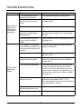
SOLUCIÓN DE PROBLEMAS
Problema Causa Solución
La recortadora
de hilo no puede
arrancarse
cuando el botón
de bloqueo
del gatillo está
pulsado.
1. La batería no está
instalada en la recortadora.
1. Instale la batería en la recortadora.
2. No hay contacto eléctrico
entre la recortadora y la
batería.
2. Retire la batería, compruebe el
contacto y vuelva a instalar la batería.
3. La batería está agotada. 3. Cargue la batería.
4. La palanca de desbloqueo y
el gatillo no
se han apretado a la vez.
4. Mantenga apretada la palanca de
desbloqueo y, a continuación, apriete el
gatillo para arrancar la recortadora de
hilo.
5. No pulse el botón de
encendido, apriete el gatillo
directamente.
5. Arranque el botón de encendido, el
indicador de encendido se disparará después.
La recortadora
de hilo se
detiene
durante el
corte.
1. La protección no está
montada en la recortadora,
causando un corte demasiado
largo y la sobrecarga del
motor.
1. Retire la batería y monte la protección
en la recortadora.
2. Se utiliza una línea de
corte gruesa.
2. Use solo líneas de corte de nylon con
0,080” de diámetro o inferior.
3. El eje del motor o el
cabezal de corte están
atascados con hierba.
3. Detenga la recortadora, retire la
batería y retire la hierba del eje del motor
y del cabezal de corte.
4. El motor se ha
sobrecargado.
4. Retire el cabezal de corte de la
hierba. E l motor volverá a funcionar
tan pronto como se haya eliminado la
sobrecarga. Al cortar, acerque y aleje
el cabezal de corte de la hierba y no
elimine más de 20 cm de longitud en un
solo corte.
5. La batería o la
recortadora de hilos están
demasiado calientes.
5. Deje que la batería se enfríe hasta
que la temperatura sea inferior a 70 ºC.
Deje que la temperatura se enfríe hasta
que la temperatura sea inferior a 284°F
(140°C).
6. La batería está
desconectada de la
herramienta.
6. Vuelva a instalar la batería.
7. La batería está agotada. 7. Cargue la batería.

28
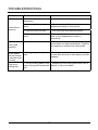
SOLUCIÓN DE PROBLEMAS
Problema Causa Solución
Las líneas no
avanzan.
1. Los hilos están soldados
entre sí.
1. Lubrique con espray de silicona.
2. No hay suciente hilo en el
carrete.
2. Instale cable extra. Consulte el apartado
"Sustitución de la línea", que aparece
anteriormente en este manual.
3. Los hilos son demasiado
cortos.
3. Tire ambos hilos, al tiempo que pulsa el
botón.
4. El hilo está enredado en
el carrete.
4. Extraiga el hilo de la bobina y vuelva a
enrollarla. Consulte el apartado "Sustitución
de la línea", que aparece anteriormente en
este manual.
El hilo sigue
rompiéndose.
1. Uso incorrecto de la
recortadora.
1. Sólo corta con la punta del hilo, evite
las piedras, muros y otros objetos duros.
Alargue el hilo de forma regular para
mantener el ancho del corte.
La hierba
se enrolla
alrededor del
cabezal de
corte y de la
cubierta del
motor.
1. Cortar hierba alta a nivel
del suelo.
1. Corte la hierba alta de arriba abajo,
eliminando no más de 20 cm en cada
pasada para evitar que se enrolle.
El hilo no corta
bien.
1. La cuchilla/hilo de corte
al borde de la protección
no está alada.
1. Ale la cuchilla/hilo de corte con
una lima o reemplácela con una nueva
cuchilla.

29
GARANTÍA LIMITADA
Por este medio y por un período de cuatro años GREENWORKS™ garantiza este producto
contra defectos en materiales, piezas o mano de obra al comprador original que cuente con
una prueba de compra. GREENWORKS™, a su sola discreción reparará o reemplazará, sin
costo algun o para el cliente, cualquier pieza defectuosa, siempre y cuando se haya hecho uso
normal de ella. Esta garantía es válida solamente para unidades utilizadas de manera personal
y que no hayan sido utilizadas o alquiladas para uso industrial o comercial, y que hayan recibido
mantenimiento de acuerdo a las instrucciones que aparecen en el manual del propietario que se
suministró con el producto nuevo.
ARTÍCULOS QUE NO CUBRE LA GARANTÍA:
1. Cualquier pieza que haya resultado inoperativa debido al mal uso, abuso, negligencia,
accidente, mantenimiento inadecuado, o modicación, o
2. La unidad, si no se ha utilizado y/o mantenido de acuerdo con el manual de propietario, o
3. Desgaste normal, excepto como se indica a continuación;
4. Elementos de mantenimiento rutinario tales como lubricantes, alado de cuchillas;
5. El deterioro normal del acabado exterior debido al uso o la exposición.
LÍNEA TELEFÓNICA PARA AYUDA DE GREENWORKS (1-855-345-3934):
Se puede obtener servicio relacionado con la garantía llamando de lunes a viernes entre a
nuestra línea gratis para ayuda, el (1-855-345-3934).
GASTOS DE TRANSPORTE:
Los gastos de transporte para el movimiento de cualquier unidad de equipos motorizados o
accesorio son responsabilidad del comprador. Es responsabilidad del comprador pagar los
gastos de transporte para cualquier pieza enviada para reemplazo bajo esta garantía a menos
que GREENWORKS™ solicite dicha devolución por escrito.

30
PLANO DE DESPIECE

31
LISTA DE PIEZAS
N.º Pieza N.º Modelo Descripción Cant.
1 34107511-10 Perilla 1
2 311121416 Conjunto de herramienta Bare 1
3 33208334 Tornillo 4
4 34130334 Mango auxiliar 1
5 34140334 Placa 1
6 333041429 Guía de bordes 1
7 332041428 Primavera 1
8 341041429AB Perilla del golpeador 1
9 311101429 Bobina 1
10 311091429 Cubierta del carrete 1
11 322011429 Arandela 2
12 32207319 Tornillo 2
13 32916131 Arandela 2
14 333011429 Cuchilla de corte 1
15 341081429AB Protector 1

LÍNEA GRATUITA LÍNEA DE AYUDA: 1-855-345-3934
Rev: 00 (11-25-15)
Greenworks Tools
PO Box 1238
Mooresville, NC 28115
-
 1
1
-
 2
2
-
 3
3
-
 4
4
-
 5
5
-
 6
6
-
 7
7
-
 8
8
-
 9
9
-
 10
10
-
 11
11
-
 12
12
-
 13
13
-
 14
14
-
 15
15
-
 16
16
-
 17
17
-
 18
18
-
 19
19
-
 20
20
-
 21
21
-
 22
22
-
 23
23
-
 24
24
-
 25
25
-
 26
26
-
 27
27
-
 28
28
-
 29
29
-
 30
30
-
 31
31
-
 32
32
-
 33
33
-
 34
34
-
 35
35
-
 36
36
-
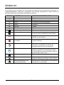 37
37
-
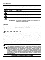 38
38
-
 39
39
-
 40
40
-
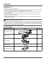 41
41
-
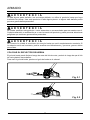 42
42
-
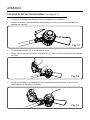 43
43
-
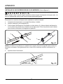 44
44
-
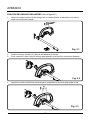 45
45
-
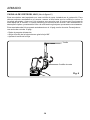 46
46
-
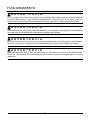 47
47
-
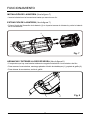 48
48
-
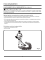 49
49
-
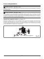 50
50
-
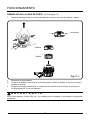 51
51
-
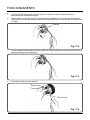 52
52
-
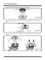 53
53
-
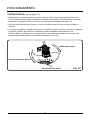 54
54
-
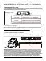 55
55
-
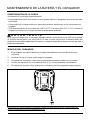 56
56
-
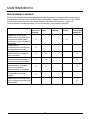 57
57
-
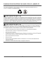 58
58
-
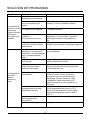 59
59
-
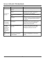 60
60
-
 61
61
-
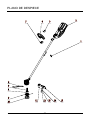 62
62
-
 63
63
-
 64
64


Greenworks Pro ST80L210 Instrucciones de operación
- Categoría
- Podadoras de césped
- Tipo
- Instrucciones de operación
en otros idiomas
Artículos relacionados
-
Greenworks Pro STBA80L210 Instrucciones de operación
-
-
-
Greenworks Pro 80V Lithium-ion Rechargeable Battery and Charger El manual del propietario
-
-
Otros documentos
-
Simplicity 1696956-00 Manual de usuario
-
Greenworks STF310 String Trimmer Manual de usuario
-
-
Ryobi RY402013BTLVNM El manual del propietario
-
Snapper 1696771 Manual de usuario
-
-
-
Ryobi P2090 El manual del propietario
-
-