Grundfos Solar 15-80 130 Installation And Operation Instruction Manual
- Tipo
- Installation And Operation Instruction Manual

INSTRUCTIONS
Solar Station
Installation and operating instructions

2
Declaration of Conformity
Grundfos Manufacturing Ltd declares, in sole responsibility, that the Grundfos Solar Station, to which this
declaration relates, are in conformity to the Essential Requirements of the following Directives:
• Machinery Directive (2006/42/EC), (EN ISO 12100: 2010).).
• Low Voltage Directive (2006/95/EC) , (EN 60335-2-51: 2003).
• Electromagnetic Compatibility Directive (2004/108/EC) , (EN 61000-6-2: 2005 & EN 61000-6-3: 2007).
Declaración de conformidad
Grundfos Manufacturing Ltd declara, en responsabilidad propia, que el Grupo Hidráulico Solar Grundfos, al que se
refiere esta declaración, se ajusta a los Requisitos Esenciales de las siguientes directivas:
• Directiva de Maquinaria (2006/42/EC), (EN ISO 12100: 2010).).
• Directiva de Bajo Voltaje (2006/95/EC) , (EN 60335-2-51: 2003).
• Directiva de Compatibilidad Electromagnética (2004/108/EC) , (EN 61000-6-2: 2005 & EN 61000-6-3: 2007).
∆ΗΛΩΣΗ ΣΥΜΜΟΡΦΩΣΗΣ
ΕΜΕΙΣ, η Grundfos Manufacturing Ltd, ∆ΗΛΩΝΟΥΜΕ, ΜΕ ΑΠΟΚΛΕΙΣΤΙΚΗ ΜΑΣ ΕΥΘΥΝΗ, ΟΤΙ Ο ΗΛΙΑΚΟΣ
ΣΤΑΘΜΟΣ GRUNDFOS, ΣΤΟΝ ΟΠΟΙΟ ΑΦΟΡΑ Η ΠΑΡΟΥΣΑ ∆ΗΛΩΣΗ, ΕΙΝΑΙ ΣΥΜΦΩΝΟΣ ΜΕ ΤΙΣ ΒΑΣΙΚΕΣ
ΑΠΑΙΤΗΣΕΙΣ ΤΩΝ ΠΑΡΑΚΑΤΩ Ο∆ΗΓΙΩΝ:
• Ο∆ΗΓΙΑ ΠΕΡΙ ΜΗΧΑΝΗΜΑΤΩΝ (2006/42/ΕΕ), (EN ISO 12100: 2010).).
• Ο∆ΗΓΙΑ ΠΕΡΙ ΧΑΜΗΛΗΣ ΤΑΣΗΣ (2006/95/ΕΕ) , (EN 60335-2-51: 2003).
• Ο∆ΗΓΙΑ ΠΕΡΙ ΗΛΕΚΤΡΟΜΑΓΝΗΤΙΚΗΣ ΣΥΜΒΑΤΟΤΗΤΑΣ (2004/108/ΕΕ) , (EN 61000-6-2: 2005 & EN 61000-
6-3: 2007).
Grundfos Manufacturing Ltd
Ferryboat Lane
Castletown
Sunderland
SR5 3JL
Signature:
Name: Terence Mole
Position: Engineering Manager
Date:

3
Solar Station
Installation and operating instructions 4
Instrucciones de instalación y funcionamiento 12
Ο∆ΗΓΙΕΣ ΕΓΚΑΤΑΣΤΑΣΗΣ ΚΑΙ ΛΕΙΤΟΥΡΓΙΑΣ 20

4
CONTENTS
Page
1. Symbols used in this document ............................................................................................................................. 4
2. General description .................................................................................................................................................5
3. Technical information............................................................................................................................................. 6
4. Applications.............................................................................................................................................................. 7
5. Installation - Wall mounting ..................................................................................................................................7
6. Pump head replacement.........................................................................................................................................7
7. Air-Separator............................................................................................................................................................ 8
8. Flow meter ...............................................................................................................................................................8
9. Electrical connection ................................................................................................................................................9
10. Filling and flushing the solar thermal system.................................................................................................... 9
10.1 Filling the system ............................................................................................................................................9
10.2 Cleaning the system...................................................................................................................................... 10
10.3 Flushing the system ......................................................................................................................................10
10.4 Shut off and non-return valves....................................................................................................................10
11. Start up.................................................................................................................................................................10
12. Spare parts and accessories ............................................................................................................................... 11
13. Disposal ................................................................................................................................................................11
Warning
Prior to installation, read these installation and operating instructions. Installation and operation
must comply with local regulations and accepted codes of good practise.
Warning
The equipment is only to be used for pumping water & glycol solutions in heating systems. Grundfos
will not be liable for any damage or injury due to equipment misuse or failure to follow these
instructions.
The equipment shall not be modified in any way. Grundfos will not be liable for any damage or
injury due to unauthorised modification of the equipment.
Do not attempt to repair the equipment: consult Grundfos in the event of any equipment failure.
Warning
The use of this product requires experience with and knowledge of the product.
Persons with reduced physical, sensory or mental capabilities must not use this product, unless they
are under supervision or have been instructed in the use of the product by a person responsible for
their safety.
Children must not use or play with this product.
1. Symbols used in this document
Warning
If these safety instructions are not observed, it may result in personal injury.
If these instructions are not observed, it may result in malfunction or damage to the equipment.
Notes or instructions that make the job easier and ensure safe operation.

5
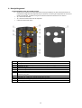
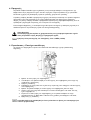
2. General description
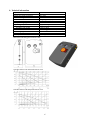
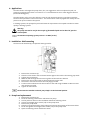
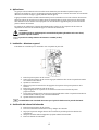
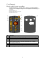
The Solar Station incorporates:
• Grundfos circulator pump (130mm centre distance) with two ball valves with integral
temperature gauges to observe the flow and return temperatures within the system. With an
internal non-return valve in the return.
• ¾” female connections.
• ¾” female expansion vessel connection.
• Connecting cable (2m).
Key Description
1 EPP insulation enclosure bottom
2 Monobloc ball valve with temperature gauge (red)- flow
3 Air-separator
4 Safety valve for solar circuit
5 Pressure gauge
6 Expansion vessel connection
7 Monobloc ball valve with temperature gauge (blue) with non-return & by-pass valves
8 Grundfos circulator pump
9 Flow regulator with fill & discharge valves
10 Hose connections for filling & draining
11 EPP insulation enclosure top

6
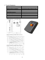
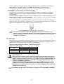
3. Technical information
Top connection ¾” female
Bottom connection ¾” female
Expansion vessel connection ¾” male
Fill & Discharge connection ¾” male & hose connection
Enclosure Polypropylene (EPP)
Gaskets EPDM
Temperature gauge 0
o
C to +160
o
C
Operating temperature:-
Grundfos solar 15-65 +2
o
C to +110
o
C
Grundfos solar 15-80 +2
o
C to +95
o
C
Fluids Water & glycol solution (50% max)
Pressure gauge 0 bar to 10 bar
Pressure relief valve calibration 6 bar
Sound pressure level <43dB(A)
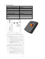
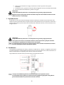
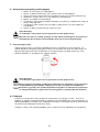
Dimensional drawing and isometric view
Grundfos Solar 15-65 130 performance curve
Grundfos Solar 15-80 130 performance curve

7
4. Applications
The Solar Station is designed to pump clean, thin, non-aggressive and non-explosive liquids, not
containing solid particles, fibres or mineral oil. It is recommended to use a water & glycol solution
(maximum 50% glycol).
The Solar Station is for use in the collector circuit of solar thermal systems in compliance with the
technical data specified in these instructions. This Solar Station comes equipped with safety valve to
prevent over pressure within the system.
In heating systems, the pumped liquid should meet the requirement of accepted standard on water
quality in heating systems.
Warning
The pump must not be used for the transfer of flammable liquids such as diesel oil, petrol or
similar liquids.
The maximum operating system pressure is 1.0 MPa (10 bar)
5. Installation - Wall mounting
The kit must be installed by a competent heating installer
1. Remove the enclosure top.
2. Place the solar station with enclosure bottom against the wall on the existing pipe work.
3. Tighten the connections.
4. Mark the wall through the two securing holes of the enclosure bottom.
5. Remove the solar station with enclosure bottom from the wall.
6. Drill holes in the wall and insert the wall plugs provided.
7. Fix the enclosure bottom with solar station to the wall using the M10 x 120mm screws
and washers provided.
8. Tighten all connections.
The unit must be installed so that the pump shaft is in the horizontal position.
6. Pump head replacement
1. Remove the enclosure top.
2. Close the isolating valves above and below the pump.
3. Let the pressure relieve in the installation below the isolating valves.
4. Loosen the hexagon allen screws (x 4) on the pump head.
5. Remove the pump head.
6. Place the new pump head in place, taking into account the position of the terminal box.
7. Re-fit and tighten the hexagon allen screws (x 4) on the pump head.
8. Open the isolating valves and fill with water.

8
Warning
The pumped liquid may be scalding hot and under high pressure!
Take care that the flat gasket is well positioned. The pump impeller should not be damaged
when re-assembling.
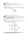
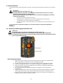
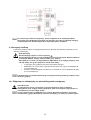
7. Air-Separator
The air-separator (or manual bleed valve) is for venting the solar thermal system. It separates the
gases within the fluid in the top of the air-separator and can be vented through partial opening of the
vent screw, as shown below using a spanner.
Warning
The pumped liquid may be scalding hot and under high pressure!
After commissioning it is recommended to vent the system daily, and then weekly or monthly,
depending on the volume of air discharged.
It is recommended that operators of solar thermal systems should manually vent the system
twice per year to achieve optimal efficiency.
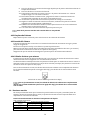
8. Flow meter
The purpose of the flow meter is for measurement and to display the flow rate of 0.5 - 15l/min. Flow
regulation is controlled using a screwdriver to open/close the ball valve. For faultless operation the
system must be flushed and free from foreign substances.
There are also two ball valves for filling and flushing the system.
For the flow meter to operate correctly it must be in the vertical position.
It is recommended that a filter is fitted into the system before the flow regulator to prevent
faulty operation from the presence of foreign substances.

9
9. Electrical connection
The electrical connection should be carried out by an authorised electrician in accordance with local
regulations.
Warning
The pump must be connected to earth
The pump must be connected to an external mains switch with a minimum contact gap of 3mm
in all poles
Before removing the terminal box cover, make sure that the power supply has been switched
off and that it cannot be accidently switched on.
• The motor required no external motor protection.
• Check that the supply voltage and frequency correspond to the values stated on the
pump.
• Connect the pump to the mains with the 2m cable supplied with the pump.
The user is to consider whether it is necessary to install an emergency stop switch.
10. Filling and flushing the solar thermal system
Warning
The system should not be filled or drained during periods of strong sunshine as
The pumped liquid may be scalding hot and under high pressure!
It is recommended only to use water & glycol solution (50% max) as solar fluid to fill and flush
the solar thermal system.
10.1 Filling the system
1. Ensure the monobloc ball valves (blue & red) are completely open (turning in the anti-clockwise
direction).
2. Connect the hose/pipe to the filling connections on the flow regulator.
3. Connect the hose/pipe to the discharge connection on the flow regulator.
4. Position the valve in the centre of the flow meter in the fill in/flush direction (see 8. Flow meter).
5. Open the fill and discharge ball valve on the flow regulator (see 8. Flow meter).
6. Flush the solar thermal system continuously, until fluid comes out of the discharge connection, for
approximately 15 minutes to remove air from the system.
7. Also during flushing, bleed the system by opening the vent screw on the air-separator (see 7. Air-
separator).
8. Close the valve on the discharge connection and allow the pressure to rise until the desired pressure
is reached.
9. Close the valve on the filling connection.

10
10. Check the pressure gauge to see if the system pressure falls – eliminate any leaks where necessary.
11. Turn on the solar circulating pump, bleeding the system from the vent screw on the air-separator
(see 7. Air-separator).
12. Increase the system pressure to the operating pressure if required.
13. Regulate the system’s flow as required, through adjusting the flow regulating valve (see 8. Flow
meter).
14. Set the speed of the pump to achieve the required performance curve (see 3. Technical information)
15. After several hours operating repeat points 11 and 12.
Prior to commissioning the system each connection should be checked.
10.2 Cleaning the system
Repeat point 1 to 6 in section 10.1 filling the system.
10.3 Flushing the system
Flushing the system is only required if the system has been filled only with water and there is a risk of
freezing.
Connect a re-cycle tank to a tap on the lower part of the system.
Operate on the blue monobloc ball valve the screw (see 10.4 Shut off and non-return valves) to keep
the non-return valve in the open position.
Ensure the discharge valves in the upper part of the system are open.
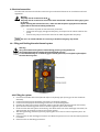
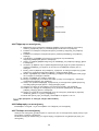
10.4 Shut off and non-return valves
The red and blue handles of the monobloc ball valves action the shut-off ball valves. These same
valves also have integrated non-return valves.
The blue monobloc ball valve allows the fluid to pass through in both directions through operating
the little screw on the valves body (see below). This allows the non-return valve to stay in the open
position.
For normal operation the shut-off ball valves should be completely open (handles turned fully in anti-
clockwise direction) and non-return valves should be closed.
Closed non-return valve (working position)
For normal operation the shut-off ball valves should be completely open (handles turned fully
in anti-clockwise direction) and non-return valves should be closed.
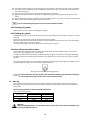
11. Start up
Do not start the pump until the system has been filled with liquid and vented (see 10. Filling and
flushing the solar thermal system). The required minimum inlet pressure must be available at the
pump inlet.
Minimum inlet pressure in relation to liquid temperature
Solar 15-65 & Solar 15-80
Minimum inlet pressure Liquid
temperature
[MPa] [bar]
≤85
o
C 0.05 0.05
90
o
C 0.027 0.27
110
o
C 0.108 1.08
Warning
When pumping hot liquids, care should be taken to ensure that persons cannot accidently come
into contact with hot surfaces.

11
There is a danger of steam emissions with safety relief valves, therefore a discharge pipe must be
connected to the ¾” internal thread of the safety valve assembly.
The minimum dynamic head for the inlet water should be available at the pump inlet during
operation to ensure satisfactory bearing life, quiet running and to avoid cavitation.
The pump must not be run dry or against a closed discharge valve.
12. Spare parts and accessories
Part number Description
97988085 Kit: Safety valve group
97988086 Kit: Flow meter - 0.5-15l/m
97988090 Kit: Monobloc solar group-supply
97988131 Kit: Monobloc solar group-return
97988132 Kit: Air-separator
13. Disposal
This product or parts of it must be disposed of in an environmentally sound way:
1. Use the public or private waste collection service.
2. If this is not possible, contact the nearest Grundfos company or service workshop.

12
ÍNDICE
Página
1. Simbología utilizada en este documento............................................................................................................. 12
2. Descripción general............................................................................................................................................... 13
3. Información técnica .............................................................................................................................................. 14
4. Aplicaciones ...........................................................................................................................................................15
5. Instalación – Montura en pared........................................................................................................................... 15
6. Sustitución del cabezal de la bomba ...................................................................................................................15
7. Separador de aire...................................................................................................................................................16
8. Caudalímetro .........................................................................................................................................................16
9. Conexión eléctrica..................................................................................................................................................17
10. Llenado y lavado del grupo hidráulico solar .....................................................................................................17
10.1 Llenado del sistema.......................................................................................................................................17
10.2 Limpieza del sistema..................................................................................................................................... 18
10.3 Lavado del sistema ........................................................................................................................................18
10.4 Válvulas de cierre y no retorno .................................................................................................................... 18
11. Puesta en marcha................................................................................................................................................18
12. Recambios y accesorios....................................................................................................................................... 19
13. Gestión de residuos.............................................................................................................................................19
Advertencia
Antes de la instalación, lea estas instrucciones. La instalación y el mantenimiento deben cumplir con
regulaciones locales y códigos de buenas prácticas aceptados.
Advertencia
El equipo ha de ser utilizado únicamente para el bombeo de soluciones de agua y glicol en sistemas de
calefacción. Grundfos no se hará responsable de ningún daño o lesión debido al mal uso del equipo o
fallo al seguir estas instrucciones.
El equipo no debe ser modificado bajo ninguna circunstancia. Grundfos no se hará cargo de ningún
daño o lesión debido a modificaciones no autorizadas del equipo.
No trate de reparar el equipo: consulte a Grundfos en caso de fallo del mismo.
Advertencia
El uso de este producto require experiencia y conocimiento del producto.
Personas con capacidad física, sensorial o mental reducida no debe utilizar este producto, a no ser que
hayan sido instruídos para ello o estén bajo supervisión de una persona responsable de su seguridad.
Los niños no deben utilizar este producto ni jugar con él.
1. Simbología utilizada en este documento
Advertencia
Si no se observan estas instucciones de seguridad, será un fallo suyo personal.
La no observación de estas instrucciones tendrá como resultado un mal funcionamiento o daño del
equipo.
Notas o instrucciones que hacen el trabajo más fácil y garantizan operaciones seguras.

13
2. Descripción general
El grupo hidráulico solar de Grundfos incluye:
• Bomba de circulación Grundfos (distancia entre ejes 130mm) con dos válvulas de bola con
indicadores integrales de temperatura para observar el caudal y las temperaturas de retorno
dentro del sistema. También incluye una válvula interna de retención en el retorno.
• ¾” conexiones hembra.
• ¾” conexión hembra del vaso de expasión
• Cable de transmisión (2m).
Nº Descripción
1 Parte posterior de la carcasa aislante EPP
2 Válvula de bola monobloque con indicador de temperatura (rojo) – caudal.
3 Separador de aire
4 Válvula de seguridad para circuíto solar
5 Indicador de presión
6 Conexión del vaso de expansión
7 Válvula de bola monobloque con indicador de temperatura (azul) con válvulas de
retención y by-pass
8 Bomba de circulación Grundfos
9 Regulador de caudal con válvulas de llenado y drenaje
10 Conexiones de manguera para llenado y drenaje
11 Parte superior de la carcasa aislante EPP

14
3. Información técnica
Conexión superior ¾” hembra
Conexión inferior ¾” hembra
Conexión del vaso de expansión ¾” macho
Conexión de llenado y drenaje ¾” male & hose connection
Carcasa de aislamiento Polipropileno (EPP)
Juntas EPDM
Indicador de temperatura 0
o
C a+160
o
C
Temperatura de funcionamiento:-
Grundfos solar 15-65 +2
o
C a +110
o
C
Grundfos solar 15-80 +2
o
C a +95
o
C
Fluidos Solución de agua y glycol (50% max)
Indicador de presión 0 bar a10 bar
Calibrado de la válvula de alivio de
presión
6 bar
Nivel de presión sonora <43dB(A)
Esquema de dimensiones y vista isométrica
Curva de rendimiento de Grundfos Solar 15-65 130
Curva de rendimiento Grundfos Solar 15-80 130

15
4. Aplicaciones
Los grupos solares hidráulicos de Grundfos están diseñados para bombear líquidos limpios, no
agresivos ni explosivos, que no contengan partículas sólidas, fibras o aceites minerales. Se recomienda
utilizar una solución de agua y glicol (máximo 50% de glicol).
El grupo hidráulico solar Grundfos está diseñado para ser utilizado en el circuito colector de sistemas
térmicos solares de acuerdo con los datos técnicos especificados en estas instrucciones. Este grupo
solar hidráulico de Grundfos viene equipado con una válvula de seguridad para prevenir exceso de
presión dentro del sistema.
En sistemas de calefacción, el líquido bombeado debe cumplir con los requisitos de las normas
aceptadas en terminos de calidad del agua en sistemas de calefacción.
Advertencia
La bomba no debe ser utilizada para la trasmisión de líquidos inflamables tales como diesel,
petróleo o líquidos similares.
La presión de trabajo máxima del sistema es 1.0 MPa (10 bar)
5. Instalación – Montura en pared
El kit debe ser instalado por un instalador con competencia para ello.
1. Retire la parte superior de la carcasa.
2. Sitúe la parte posterior de la carcasa el grupo hidráulico solar contra la pared encima de
los conductos de tuberías.
3. Apriete las conexiones.
4. Marque la pared a través de los dos agujeros de sujeción de la parte posterior de la
carcasa.
5. Retire el grupo hidráulico solar de la pared.
6. Haga los agujeros en la pared con un taladro e inserte los enchufes de pared
proporcionados.
7. Fije la parte posterior de la carcasa con el grupo hidráulico solar a la pared utilizando los
tornillos M10 x 120mm y las arandelas facilitadas.
8. Apriete todas las conexiones.
La unidad debe estar instalada de manera que el eje de la bomba esté en posición horizntal.
6. Sustitución del cabezal de la bomba
1. Retire la parte superior de la carcasa.
2. Cierre las vávulas de aislamiento arriba y debajo de la bomba.
3. Deje que la presión mitigue dentro de la instalación por debajo de las válvulas de
aislamiento.
4. Afloje los tornillos allen hexagonales (x 4) del cabezal de la bomba.
5. Retire el cabezal de la bomba.

16
6. Sitúe el nuevo cabezal en su lugar, teniendo en cuenta la posición de la caja de
terminales.
7. Coloque de nuevo y apriete los tornillos allen hexagonales (x 4) en el cabezal de la bomba.
8. Abra las válvulas de aislamiento y rellene con agua.
Advertencia
¡El líquido bombeado puede estar a una temperatura muy elevada y bajo presión alta!
Asegúrese de que la junta plana esté bien colocada. El impulsor de la bomba no debería resultar
dañado durante el reensamblaje.
7. Separador de aire
El separador de aire (la la válvula de purga manual) se utiliza para ventilar el sistema térmico solar.
Separa los gases dentro del fluído en la parte superior del separador de aire así puede ser ventilado a
través de una apertura parcial del tornillo de ventilación utilizando una llave, como se muestra en la
imagen inferior.
Advertencia
¡El líquido bombeado puede estar a una temperatura muy elevada y bajo presión alta!
Tras la puesta en marcha se recomienda ventilar el sistema diariamente y después semanal o
mensualmente, dependiendo del volumen de aire descargado.
Se recomienda que los operarios de sistemas térmicos solares ventilen manualmente el sistema
dos veces al año para alcanzar una eficiencia óptima.
8. Caudalímetro
La finalidad del caudalímetro es medir y y mostrar el caudal de 0.5 - 15l/min. La regulación del caudal
se realiza utilizando un destornillador para abrir/cerrar la vávula de bola. Para un funcionamiento sin
fallos el sistema debe ser limpiado y estar libre de sustancias extrañas.
Hay también dos válvulas de bola para el llenado y la limpieza del sistema.
Para que el caudalímetro funcione correctamente debe estar en posición vertical.
Se recomienda colocar el filtro en el sistema antes del regulador de flujo para evitar fallos de
funcionamiento debido a la presencia de sustancias extrañas.

17
9. Conexión eléctrica
La conexión eléctrica debe ser llevada a cabo por un electricista autorizado de acuerdo a la normativa
local.
Advertencia
La bomba debe estar conectada a tierra .
La bomba debe estar conectada a un conmutador de alimentación externa con un espacio
mínimo de contacto de 3mm en todos los polos.
Antes de retirar la tapa de la caja, asegúrese de que corriente ha sido apagada y no puede ser
activada accidentalmente.
• El motor no necesita protección externa.
• Compruebe que el voltaje de la corriente de alimentación y la frecuencia
corresponden a los valores indicados en la bomba.
• Conecte la bomba a la corriente eléctrica con el cable de 2m suministrado junto con
la bomba.
El usuario es el que debe considerar si es necesario instalar un interruptor de parada de
emergencia.
10. Llenado y lavado del grupo hidráulico solar
Advertencia
El sistema no debe ser llenado o drenado durante períodos de fuerte sol.
¡El líquido bombeado puede estar a una temperatura muy elevada y bajo presión alta!
Se recomienda utilizar únicamente soluciones de agua y glicol (50% máx.) como fluído para llenar
y lavar el grupo hidráulico solar.
10.1 Llenado del sistema
1. Aegúrese de que las válvulas de bola monobloque (azul y roja) están completamente
abiertas (girándolas en sentido contrario a las agujas del reloj).
2. Conecte la manguera/tubería a las conexiones de llenado en el regulador de caudal.
3. Conecte la manguera/tubería a la conexion de descarga en el regulador de caudal.
4. Sitúe la vávula en el centro del caudalímetro en la dirección de llenado/limplieza (fill
in/flush) (véase 8. Caudalímetro).
5. Abra la válvula de bola de llenado y descarga en el regulador de caudal (véase 8.
Caudalímetro).
6. Limpie el sistema térmico solar continuamente, hasta que el fluído salga de la conexión
de descarga durante 15 minutos aproximadamente para eliminar el aire del sistema.
7. Purgue el sistema, también durante la limpieza, abriendo el tornillo de ventilación en el
separador de aire (véase 7. Separador de aire).

18
8. Cierre la válvula en la conexion de descarga dejando que la presión suba hasta alcanzar la
temperatura deseada.
9. Cierre la válvula en la conexion de llenado.
10. Compruebe el indicador de presión para ver si la presión del sistema cae – elimine
cualquier fuga si en caso de ser necesario.
11. Encienda la bomba circulatoria solar, purgando el sistema a través del tornillo de
ventilación del separador de aire (véase 7. Separador de aire).
12. Incremente la presión del sistema hasta la presión de trabajo, si es necesario.
13. Regule el caudal del sistema cuando sea necesario, mediante el ajuste de la válvula
reguladora de caudal (véase 8. Caudalímetro).
14. Establezca la velocidad de la bomba necesaria para alcanzar la curva de rendimiento
deseada (véase 3. Información técnica)
15. Tras varias horas de funcionamiento repita los puntos 11 y 12.
Antes de la puesta en marcha cada conexión debe ser comprobada.
10.2 Limpieza del sistema
Repita desde el punto 1 hasta el punto 6 de la sección 10.1 Llenado del sistema.
10.3 Lavado del sistema
El lavado del sistema solo es necesario si el sistema ha sido llenado unicamente con agua y existe
riesgo de congelación.
Conecte un tanque de reciclaje a una llave en la parte baja del sistema.
Mueva el tornillo de la válvula de bola monobloque azul (véase 10.4 Válvulas de cierre y no retorno)
para mantener la válvula de no retorno en la posición abrir (open).
Asegúrese de que las válvulas de descarga de la parte superior del sistema están abiertas.
10.4 Válvulas de cierre y no retorno
El manejo de las válvulas de bola monobloque azul y roja acciona las vávulas de bola de cierre. Estas
mismas válvulas tienen integradas a su vez válvulas de no retorno.
La válvula de bola monobloque de color azul permite al fluído pasar en ambas direcciones al mover el
pequeño tornillo que se encuentra en el cuerpo de las válvulas (ver abajo). Eso permite a la válvula de
no retorno estar en la posición abir (open)
Para un funcionamiento normal, las válvulas de bola de cierre deben estar completamente abiertas
(en el sentido totalmente opuesto a las agujas del reloj) y las válvulas de no retorno deben estar
cerradas.
Válvula de no retorno cerrada (posición de trabajo)
Para un funcionamiento normal, las válvulas de bola de cierre deben estar completamente
abiertas (en el sentido totalmente opuesto a las agujas del reloj) y las válvulas de no retorno deben
estar cerradas.
11. Puesta en marcha
No arranque la bomba hasta que el sistema haya sido llenado con líquido y ventilado (véase 10.
Llenado y lavado del sistema térmico solar). La presión de entrada mínima requerida debe estar
disponible en la entrada de la bomba.
Presión de entrada mínima en relación a la temperature del líquido
Solar 15-65 & Solar 15-80
Presión de entrada mínima Temperatura del
líquido
[MPa] [bar]
≤85
o
C 0.05 0.05
90
o
C 0.027 0.27
110
o
C 0.108 1.08

19
Advertencia
Al bombear líquidos calientes, debe tener cuidado y asegurarse de que las personas no puedan
tener contacto accidentalmente con superficies a altas temperaturas.
Existe peligro de emisiones de vapor con las válvulas de seguridad, por lo tanto una tubería de
descarga debe estar conectada a la rosca interior de ¾” de la válvula de seguridad.
La carga dinámica mínima para el agua de entrada debería estar disponible en la entrada de la
bomba durante la operación para asegurar una vida útil satisfactoria, funcionamiento silencioso
del sistema y evitar cavitación.
La bomba no debe ser activada en seco o con una válvula de descarga cerrada.
12. Recambios y accesorios
Número de
partida
Descripción
97988085 Kit: válvulas de seguridad
97988086 Kit: Caudalímetro - 0.5-15l/m
97988090 Kit: Grupo solar monobloque-suministro
97988131 Kit: Grupo solar monobloque-retorno
97988132 Kit: Separador de aire
13. Gestión de residuos
Este producto o componentes del mismo deben ser tratados de una manera responsable con el medio
ambiente:
1. Utilice un sistema de gestión de residuos público o privado.
2. Si esto no es possible, contacte con la compañía o el taller Grundfos más cercano.

20
ΠΕΡΙΕΧΟΜΕΝΑ
ΣΕΛΙ∆Α
1. Σύµβολα που χρησιµοποιούνται στο παρόν έγγραφο.............................................................................................. 20
2. Γενική Περιγραφή ..................................................................................................................................................21
3. Τεχνικές Πληροφορίες............................................................................................................................................. 22
4. Εφαρµογές ...............................................................................................................................................................23
5. Εγκατάσταση – Επιτοίχια τοποθέτηση ....................................................................................................................23
6. Αντικατάσταση κεφαλής κυκλοφορητή ..................................................................................................................24
7. ∆ιαχωριστήρας αέρα................................................................................................................................................ 24
8. Ροόµετρο .................................................................................................................................................................24
9. Ηλεκτρική σύνδεση ..................................................................................................................................................25
10. Πλήρωση και καθαρισµός του ηλιακού θερµικού συστήµατος ............................................................................25
10.1 Πλήρωση του συστήµατος .............................................................................................................................. 26
10.2 Καθαρισµός του συστήµατος ..........................................................................................................................26
10.3 Ξέπλυµα του συστήµατος................................................................................................................................26
10.4 Βαλβίδες κλεισίµατος και αντεπιστροφής.......................................................................................................27
11. Εκκίνηση ...............................................................................................................................................................27
12. Ανταλλακτικά και πρόσθετος εξοπλισµός.............................................................................................................28
13. Απόρριψη ..............................................................................................................................................................28
Προειδοποίηση
Πριν από την εγκατάσταση, διαβάστε τις παρούσες οδηγίες εγκατάστασης και λειτουργίας.
Η εγκατάσταση και η λειτουργία πρέπει να είναι σύµφωνες µε
τους τοπικούς κανονισµούς και τους παραδεκτούς κανόνες καλής χρήσης.
Προειδοποίηση
Ο παρών εξοπλισµός προορίζεται αποκλειστικά για την άντληση νερού & διαλυµάτων
γλυκόλης στα συστήµατα θέρµανσης. Η Grundos δεν θα θεωρείται υπεύθυνη για
οποιαδήποτε ζηµιά ή τραυµατισµό προκληθεί λόγω κακής χρήσης του εξοπλισµού ή µη
τήρησης των οδηγιών.
Ο εξοπλισµός δεν πρέπει να υφίσταται οποιουδήποτε είδους τροποποίηση. Η Grundfos
δεν θα θεωρείται υπεύθυνη για οποιαδήποτε ζηµιά ή τραυµατισµό λόγω µη
εξουσιοδοτηµένης τροποποίησης του εξοπλισµού.
Μην επιχειρείτε να επιδιορθώσετε τον εξοπλισµό: συµβουλευτείτε την Grundfos σε
περίπτωση βλάβης του εξοπλισµού.
Προειδοποίηση
Η χρήση του παρόντος προϊόντος προϋποθέτει εµπειρία και γνώση του χειρισµού του.
Άτοµα µε µειωµένες φυσικές, αισθητικές ή νοητικές ικανότητες δεν πρέπει να
χρησιµοποιούν αυτό το προϊόν εκτός εάν υπάρχει επίβλεψη ή έχουν εκπαιδευτεί σχετικά µε τη
χρήση του προϊόντος από τον υπεύθυνο για την ασφάλειά τους.
Τα παιδιά δεν θα πρέπει να χρησιµοποιούν ή να παίζουν µε αυτό το προϊόν.
1. Σύµβολα που χρησιµοποιούνται στο παρόν έγγραφο
Προειδοποίηση
Σε περίπτωση που δεν τηρούνται οι παρούσες οδηγίες ασφαλείας, µπορεί να υπάρξει
τραυµατισµός,
Σε περίπτωση που δεν τηρούνται οι παρούσες οδηγίες, µπορεί να προκληθεί βλάβη ή
καταστροφή του εξοπλισµού,
Σηµειώσεις ή οδηγίες που διευκολύνουν τις εργασίες και εξασφαλίζουν ασφαλή λειτουργία.

21
2. Γενική Περιγραφή
Ο Ηλιακός σταθµός Grundofs περιλαµβάνει:
• Κυκλοφορητή της Grundfos (απόσταση στοµίων 130 mm) µε δύο σφαιρικές βαλβίδες µε
ενσωµατωµένα µανόµετρα θερµοκρασίας για την παρακολούθηση των θερµοκρασιών
προσαγωγής και επιστροφής στο σύστηµα. Με µία εσωτερική βαλβίδα αντεπιστροφής στην
επιστροφή.
• Θηλυκές συνδέσεις ¾.
• Θηλυκή σύνδεση δοχείου διαστολής.
• Καλώδιο σύνδεσης (2m).
Αρ. Περιγραφή
1
Κάτω περίβληµα µόνωσης ΕΡΡ
2
Σφαιρική βαλβίδα µονοµπλόκ µε µανόµετρο θερµοκρασίας (Κόκκινη) – παροχή
3
∆ιαχωριστής αέρα
4
Βαλβίδα ασφαλείας για ηλιακό κύκλωµα
5
Μανόµετρο
6
Σύνδεση δοχείου διαστολής
7
Σφαιρική βαλβίδα µονοµπλοκ µε µανόµετρο θερµοκρασίας (µπλε) µε βαλβίδες
αντεπιστροφής & διακλάδωσης
8
Κυκλοφορητής Grundfos
9
Ρυθµιστής παροχής µε βαλβίδες πλήρωσης & κατάθλιψης
10
Συνδέσεις εύκαµπτου σωλήνα για πλήρωση & αποχέτευση
11
Πάνω περίβληµα µόνωσης ΕΡΡ

22
3. Τεχνικές Πληροφορίες
Πάνω σύνδεση ¾” Θηλυκή
Κάτω σύνδεση ¾” Θηλυκή
Σύνδεση δοχείου διαστολής ¾” Αρσενική
Σύνδεση πλήρωσης & κατάθλιψης ¾” Αρσενική & σύνδεση εύκαµπτου σωλήνα
Περίβληµα Πολυπροπυλένιο (ΕΡΡ)
Τσιµούχες ΕRDM
Μανόµετρο θερµοκρασίας 0
o
έως +160
o
C
Θερµοκρασία λειτουργίας:-
Ηλιακός Σταθµός Grundfos15-65 +2
o
C έως +110
o
C
Ηλιακός Σταθµός Grundfos 15- 80 +2
o
C έως +95
o
C
Υγρά ∆ιάλυµα νερού & γλυκόλης (µέγ. 50%)
Μανόµετρο 0 bar έως 10 bar
Βαθµονόµηση ανακουφιστικής βαλβίδας 6 bar
Στάθµη ηχητικής πίεσης <43dB(A)
Σχέδιο µε διαστάσεις και ισοµετρική άποψη
Καµπύλη απόδοσης Grundfos Solar 15-65 130
Καµπύλη απόδοσης Grundfos Solar 15-80 130

23
4. Εφαρµογές
Οι ηλιακοί σταθµοί Grundfos έχουν σχεδιαστεί για την άντληση καθαρών, λεπτόρρευστων, µη
διαβρωτικών και µη εκρηκτικών υγρών που δεν περιέχουν στερεά σωµατίδια, ίνες ή ορυκτέλαια.
Συνιστάται η χρήση ενός διαλύµατος νερού και γλυκόλης (µέγιστο 50% γλυκόλη).
Ο ηλιακός σταθµός Grundfos προορίζεται για χρήση στο κύκλωµα συλλέκτη των ηλιακών θερµικών
συστηµάτων που είναι σύµφωνα µε τα τεχνικά χαρακτηριστικά που ορίζονται στις παρούσες
οδηγίες. Ο ηλιακός σταθµός Grundfos προµηθεύεται εξοπλισµένος µε βαλβίδα ασφαλείας ώστε να
εµποδίζεται η δηµιουργία υπερπίεσης στο εσωτερικό του συστήµατος.
Στα συστήµατα θέρµανσης, το αντλούµενο υγρό θα πρέπει να πληροί τις απαιτήσεις σχετικά µε το
αποδεκτό πρότυπο περί ποιότητας νερού στα συστήµατα θέρµανσης.
Προειδοποίηση
Ο κυκλοφορητής δεν πρέπει να χρησιµοποιείται για τη µεταφορά εύφλεκτων υγρών
όπως πετρελαίου ντίζελ, βενζίνης ή παρεµφερών υγρών,
Η µέγιστη πίεση λειτουργίας του συστήµατος είναι 1,0 MPa (10 bar)
5. Εγκατάσταση – Επιτοίχια τοποθέτηση
Το σύνολο των εξαρτηµάτων πρέπει να τοποθετείται από αδειούχο τεχνίτη εγκατάστασης
θέρµανσης
1. Βγάλτε το πάνω µέρος του περιβλήµατος,
2. Τοποθετήστε τον ηλιακό σταθµό µε το κάτω µέρος του περιβλήµατος στον τοίχο στις
υπάρχουσες σωληνώσεις,
3. Σφίξτε τις συνδέσεις,
4. Σηµαδέψτε τον τοίχο µέσα από τις δύο οπές στερέωσης που υπάρχουν στο κάτω µέρος
του περιβλήµατος,
5. Βγάλτε τον ηλιακό σταθµό µε το κάτω µέρος του περιβλήµατος από τον τοίχο,
6. Ανοίξτε οπές στον τοίχο και τοποθετήστε τα ούπα που θα βρείτε στα υλικά που σας
έχουν προµηθευτεί,
7. Στερεώστε το κάτω µέρος του περιβλήµατος µε τον ηλιακό σταθµό στον τοίχο
χρησιµοποιώντας τις βίδες ΜΙ0 x 120 mm και τις ροδέλες που θα βρείτε στα υλικά,
8. Σφίξτε όλες τις συνδέσεις.
Η µονάδα πρέπει να τοποθετηθεί µε τέτοιο τρόπο ώστε ο άξονας του κυκλοφορητή να
είναι σε οριζόντια θέση.

24
6. Αντικατάσταση κεφαλής κυκλοφορητή
1. Βγάλτε το πάνω µέρος του περιβλήµατος,
2. Κλείστε τις βάνες αποµόνωσης πάνω και κάτω από τον κυκλοφορητή,
3. Αφήστε την πίεση να εκτονωθεί στην εγκατάσταση κάτω από τις βάνες αποµόνωσης,
4. Χαλαρώστε τις βίδες άλλεν (x 4) στην κεφαλή του κυκλοφορητή.
5. Βγάλτε την κεφαλή του κυκλοφορητή,
6. Τοποθετήστε την καινούρια κεφαλή κυκλοφορητή στη θέση της, λαµβάνοντας υπόψη τη
θέση του ακροκιβωτίου,
7. Τοποθετήστε ξανά στη θέση τους και σφίξτε τις βίδες άλλεν (x 4) στην κεφαλή του
κυκλοφορητή,
8. Ανοίξτε τις βάνες αποµόνωσης και γεµίστε µε νερό.
Προειδοποίηση
Το αντλούµενο υγρό µπορεί να είναι ζεµατιστό και υπό υψηλή πίεση!
Φροντίστε έτσι ώστε η επίπεδη τσιµούχα να είναι σωστά τοποθετηµένη. Η πτερωτή του
κυκλοφορητή δεν θα πρέπει να καταστραφεί κατά την εκ νέου συναρµολόγηση.
7. ∆ιαχωριστήρας αέρα
Ο διαχωριστήρας αέρα (ή χειροκίνητη βαλβίδα εκτόνωσης) προορίζεται για την εξαέρωση του
ηλιακού θερµικού συστήµατος. ∆ιαχωρίζει τα αέρια στο εσωτερικό του υγρού στο πάνω µέρος του
διαχωριστήρα αέρα και µπορεί να εξαερωθεί µε το µερικό άνοιγµα της βίδας εξαέρωσης, όπως
φαίνεται παρακάτω µε τη βοήθεια ενός γαλλικού κλειδιού.
Προειδοποίηση
Το αντλούµενο υγρό µπορεί να είναι ζεµατιστό και υπό υψηλή πίεση!
Μετά το ξεκίνηµα συνιστάται η καθηµερινή εξαέρωση του συστήµατος και στη συνέχεια
σε εβδοµαδιαία ή µηνιαία βάση, ανάλογα µε τον όγκο του αέρα που αποβάλλεται.
Συνιστάται οι χειριστές των ηλιακών θερµικών συστηµάτων να εξαερώνουν χειροκίνητα
το σύστηµα δύο φορές το χρόνο ώστε να επιτυγχάνεται η καλύτερη δυνατή απόδοση.
8. Ροόµετρο
Ο σκοπός του ροόµετρου είναι η µέτρηση και η απεικόνιση της παροχής των 0,5 – 15 l/min. Η
ρύθµιση της παροχής πραγµατοποιείται µε τη βοήθεια ενός κατσαβιδιού για το άνοιγµα/κλείσιµο της
σφαιρικής βαλβίδας. Για οµαλή χωρίς προβλήµατα λειτουργία, το σύστηµα πρέπει να ξεπλένεται µε
νερό και να είναι απαλλαγµένο από ξένες ουσίες.
Υπάρχουν, επίσης, δύο σφαιρικές βαλβίδες για την πλήρωση και τον καθαρισµό του συστήµατος.

25
Για να λειτουργεί σωστά το ροόµετρο, πρέπει να βρίσκεται σε κατακόρυφη θέση.
Συνιστούµε να τοποθετηθεί ένα φίλτρο στο σύστηµα, πριν από το ρυθµιστή παροχής,
για προστασία από δυσλειτουργία λόγω παρουσίας ξένων σωµάτων.
9. Ηλεκτρική σύνδεση
Η ηλεκτρική σύνδεση πρέπει να πραγµατοποιείται από αδειούχο ηλεκτρολόγο σύµφωνα µε τους
τοπικούς κανονισµούς.
Προειδοποίηση
Ο κυκλοφορητής πρέπει να είναι γειωµένος
Ο κυκλοφορητής πρέπει να είναι συνδεδεµένος σε έναν εξωτερικό διακόπτη δικτύου
µε ελάχιστο διάκενο επαφής 3 mm σε όλους τους πόλους.
Πριν βγάλετε το καπάκι του ακροκιβωτίου, βεβαιωθείτε ότι η παροχή ρεύµατος είναι
κλειστή καθώς και όχι δεν µπορεί να ανοίξει κατά λάθος.
• Ο κινητήρας δεν χρειάζεται εξωτερική προστασία κινητήρα.
• Βεβαιωθείτε ότι η τάση και η συχνότητα αντιστοιχούν στις τιµές που αναφέρονται
στον κυκλοφορητή
• Συνδέστε τον κυκλοφορητή στο δίκτυο µε το καλώδιο 2 m που προµηθεύεται µαζί
µε τον κυκλοφορητή.
Η εγκατάσταση ενός διακόπτη διακοπής λειτουργίας έκτακτης ανάγκης επαφίεται στην
κρίση του χρήστη.
10. Πλήρωση και καθαρισµός του ηλιακού θερµικού συστήµατος
Προειδοποίηση
Το σύστηµα δεν πρέπει να γεµίζεται ή να αποστραγγίζεται κατά τη διάρκεια
διαστηµάτων όπου υπάρχει έντονη ηλιοφάνεια γιατί το αντλούµενο υγρό µπορεί να
είναι ζεµατιστό και υπό υψηλή πίεση!
Για την πλήρωση και τον καθαρισµό του ηλιακού θερµικού συστήµατος συνιστάται
αποκλειστικά η χρήση διαλύµατος νερού και γλυκόλης (µέγ. 50%) ως ηλιακού υγρού.

26
10.1 Πλήρωση του συστήµατος
1. Βεβαιωθείτε ότι οι µονοµπλοκ σφαιρικές βαλβίδες (µπλε και κόκκινη) είναι τελείως
ανοικτές (στρέφοντας προς την αντίθεση φορά των δεικτών του ρολογιού).
2. Συνδέστε τον εύκαµπτο σωλήνα/σωλήνα στις συνδέσεις πλήρωσης στο ρυθµιστή
παροχής.
3. Συνδέστε τον εύκαµπτο σωλήνα/σωλήνα στη σύνδεση κατάθλιψης στο ρυθµιστή
παροχής.
4. Τοποθετήστε τη βαλβίδα στο κέντρο του ροοµέτρου στην κατεύθυνση
πλήρωσης/καθαρισµού (βλέπε 8. Ροόµετρο).
5. Ανοίξτε τη σφαιρική βαλβίδα πλήρωσης και κατάθλιψης στο ρυθµιστή παροχής (βλέπε
8. Ροόµετρο).
6. Ξεπλύνετε µε άφθονο νερό το ηλιακό θερµικό σύστηµα µέχρι να εξέλθει νερό από τη
σύνδεση κατάθλιψης, για περίπου 15 λεπτά ώστε να αφαιρεθεί ο αέρας από το
σύστηµα.
7. Επίσης, κατά τη διάρκεια του ξεπλύµατος, εξαερώστε το σύστηµα ανοίγοντας τη βίδα
εξαέρωσης στο διαχωριστήρα αέρα (βλέπε 7. ∆ιαχωριστήρας αέρα).
8. Κλείστε τη βαλβίδα στη σύνδεση κατάθλιψης και αφήστε να δηµιουργηθεί πίεση µέχρι
να επιτευχθεί το επιθυµητό επίπεδο.
9. Κλείστε τη βαλβίδα στη σύνδεση πλήρωσης.
10. Ελέγξτε το µανόµετρο για να δείτε εάν πέφτει η πίεση του συστήµατος – απαλείψτε
οποιεσδήποτε διαρροές εάν χρειάζεται.
11. Ανοίξτε τον ηλιακό κυκλοφορητή, εξαερώνοντας το σύστηµα από τη βίδα εξαέρωσης
στον διαχωριστήρα αέρα (βλέπε 7. ∆ιαχωριστήρας αέρα).
12. Αυξήστε την πίεση του συστήµατος στην πίεση λειτουργίας, εάν χρειάζεται.
13. Ρυθµίστε την παροχή του συστήµατος όπως απαιτείται, ρυθµίζοντας τη βαλβίδα
ρύθµισης παροχής (βλέπε 8. Ροόµετρο).
14. Ορίστε την ταχύτητα του κυκλοφορητή ώστε να επιτευχθεί η απαιτούµενη καµπύλη
απόδοσης (βλέπε 3. Τεχνικές πληροφορίες).
15. Μετά από αρκετές ώρες λειτουργίας, επαναλάβετε τα σηµεία 11 και 12
Πριν ξεκινήσετε το σύστηµα, ελέγξτε κάθε σύνδεση.
10.2 Καθαρισµός του συστήµατος
Επαναλάβετε τα σηµεία 1 ως 6 στο κεφάλαιο 10.1 Πλήρωση του συστήµατος.
10.3 Ξέπλυµα του συστήµατος
Ξέπλυµα του συστήµατος χρειάζεται µόνο σε περίπτωση που το σύστηµα είναι γεµάτο µόνο µε νερό
και υπάρχει ο κίνδυνος να παγώσει.
Συνδέστε ένα δοχείο ανακύκλωσης στο σηµείο λήψης που βρίσκεται στο χαµηλότερο µέρος του
συστήµατος.

27
Κινήστε τη βίδα στην µπλε µονοµπλόκ σφαιρική βαλβίδα (βλέπε 10.4 Βαλβίδες κλεισίµατος και
αντεπιστροφής) ώστε να διατηρήσετε τη βαλβίδα αντεπιστροφής στην ανοικτή θέση.
Βεβαιωθείτε ότι οι βαλβίδες κατάθλιψης στο πάνω µέρος του συστήµατος είναι ανοικτές.
10.4 Βαλβίδες κλεισίµατος και αντεπιστροφής
Οι κόκκινες και οι µπλε λαβές στις µονοµπλοκ σφαιρικές βαλβίδες ενεργοποιούν τις σφαιρικές
βαλβίδες κλεισίµατος. Αυτές οι ίδιες οι βαλβίδες διαθέτουν, επίσης, ενσωµατωµένες βαλβίδες
αντεπιστροφής.
Η µπλε µονοµπλοκ βαλβίδα επιτρέπει στο υγρό να περάσει και προς τις δύο κατευθύνσεις µε τη
βοήθεια µία µικρής βίδας στο σώµα των βαλβίδων (βλέπε παρακάτω). Αυτό επιτρέπει στη βαλβίδα
αντεπιστροφής να παραµένει στην ανοικτή θέση.
Για κανονική λειτουργία, οι σφαιρικές βαλβίδες κλεισίµατος θα πρέπει να είναι τελείως ανοικτές (οι
λαβές θα πρέπει να είναι πλήρως στραµµένες προς την αντίθετη φορά της κίνησης των δεικτών του
ρολογιού) και οι βαλβίδες αντεπιστροφής θα πρέπει να είναι κλειστές.
Κλειστή βαλβίδα αντεπιστροφής (θέση λειτουργίας)
Για κανονική λειτουργία, οι σφαιρικές βαλβίδες κλεισίµατος θα πρέπει να είναι
τελείως ανοικτές (οι λαβές θα πρέπει να είναι πλήρως στραµµένες προς την αντίθετη
φορά της κίνησης των δεικτών του ρολογιού) και οι βαλβίδες αντεπιστροφής θα
πρέπει να είναι κλειστές.
11. Εκκίνηση
Μην εκκινήσετε τον κυκλοφορητή µέχρι το σύστηµα να γεµίσει µε υγρό και να εξαερωθεί (βλέπε 10.
Πλήρωση και καθαρισµός του ηλιακού θερµικού συστήµατος). Η απαιτούµενη ελάχιστη πίεση
εισόδου πρέπει να είναι διαθέσιµη στην είσοδο του κυκλοφορητή.
Ελάχιστη πίεση εισόδου σε σχέση µε τη θερµοκρασία υγρού
Solar 15-65 & Solar 15-80
Ελάχιστη πίεση εισόδου Θερµοκρασία
υγρού
[MPa] [bar]
≤85
o
C 0,05 0,05
90
o
C 0,027 0,27
110
o
C 0,108 1,08
Προειδοποίηση
Κατά την άντληση ζεστών υγρών, πρέπει να ληφθούν τα απαραίτητα µέτρα ώστε να
εξασφαλιστεί ότι τα άτοµα δεν θα έρθουν τυχαία σε επαφή µε τις καυτές επιφάνειες.
Υπάρχει κίνδυνος εκποµπής ατµού από τις βαλβίδες εκτόνωσης ασφαλείας. Έτσι θα
πρέπει να συνδεθεί ένας σωλήνας αποχέτευσης στο εσωτερικό σπείρωµα ¾’’ του
σώµατος της βαλβίδας ασφαλείας.
Το ελάχιστο δυναµικό µανοµετρικό ύψος για το νερό εισόδου θα πρέπει να είναι
διαθέσιµο στην είσοδο του κυκλοφορητή κατά τη διάρκεια της λειτουργίας ώστε να
εξασφαλίζεται ικανοποιητική διάρκεια ζωής για τα έδρανα, αθόρυβη λειτουργία και να
αποφεύγεται η σπηλαίωση.
Ο κυκλοφορητής δεν πρέπει να λειτουργεί εν ξηρώ ή µε κλειστή βαλβίδα κατάθλιψης.

28
12. Ανταλλακτικά και πρόσθετος εξοπλισµός
Αρ. εξαρτήµατος
Περιγραφή
97988085
Σετ: Μονάδα βαλβίδας ασφαλείας
97988086
Σετ: Ροόµετρο – 0,515 l/m
97988090
Σετ: Μονοµπλόκ µονάδα παροχής ηλιακού
97988131
Σετ: Μονοµπλόκ µονάδα επιστροφής ηλιακού
97988132
Σετ: ∆ιαχωριστήρας αέρα
13. Απόρριψη
Το παρόν προϊόν ή τα εξαρτήµατά του πρέπει να απορρίπτονται µε τρόπο φιλικό προς το
περιβάλλον:
1. Χρησιµοποιήστε τη δηµόσια ή την ιδιωτική υπηρεσία συλλογής αποβλήτων
2. Εάν αυτό δεν είναι δυνατόν, επικοινωνήστε µε την πλησιέστερη εταιρία ή συνεργείο της
Grundfos.

29

30

31
Greece
GRUNDFOS Hella A.E.B.E.
20th km. Athinon-Markopoulou Av.
P.O. Box 71
GR-19002 Peania
Tel: +0030-210-66 83 400
Telefax: +0030-210-66 46 273
Spain
Bombas GRUNDFOS España S.A.
Comino de la Fuentecilla, s/n
E-28110 Algete (Madrid)
Tel: +34-91-848 8800
Telefax: +34-91-628 0465
United Kingdom
GRUNDFOS Pumps Ltd.
Grovebury Road
Leighton Buzzard/Bed. LU7 8TL
Tel: +44-1525-850000
Telefax: +44-1525-850011

98096720 1110
-
 1
1
-
 2
2
-
 3
3
-
 4
4
-
 5
5
-
 6
6
-
 7
7
-
 8
8
-
 9
9
-
 10
10
-
 11
11
-
 12
12
-
 13
13
-
 14
14
-
 15
15
-
 16
16
-
 17
17
-
 18
18
-
 19
19
-
 20
20
-
 21
21
-
 22
22
-
 23
23
-
 24
24
-
 25
25
-
 26
26
-
 27
27
-
 28
28
-
 29
29
-
 30
30
-
 31
31
-
 32
32


Grundfos Solar 15-80 130 Installation And Operation Instruction Manual
- Tipo
- Installation And Operation Instruction Manual
En otros idiomas
- English: Grundfos Solar 15-80 130
Documentos relacionados
-
Grundfos 99287259 Guía de instalación
-
-
-
-
-
-
Grundfos CRT series Installation And Operating Instructions Manual
-
-