
USER MANUAL
MANUAL DE USUARIO
USB PLAYER & MIDI CONTROLLER
.
C/ Praga nº11 Pol. Ind. Cova Solera
.
08191 Rubí Barcelona (SPAIN)
www.akiyamadj.com

1
ESPAÑOL
CAUTION
RISK OF ELECTRIC SHOCK
DO NOT OPEN
ATENCIÓN: para reducir el riesgo de electrocución, no
manipule el interior del equipo.
Para realizar el mantenimiento del equipo póngase en contacto
con el personal cualificado
Esta señal indica la presencia de lugares donde
habiendo un elevado voltaje no presentan
aislamiento y por tanto constituye un claro
riesgo de electrocución.
Esta señal indica la presencia de componentes
del equipo que precisan de mantenimiento. Para
m s información sobre stos lea el manual.á é
ATENCIÓN
PARA EVITAR RIESGO DE ELECTROCUCIÓN ASEGÚRESE DE QUE EN CASO DE NO USAR UNA CONEXIÓN AC CON TOMA DE TIERRA LOS CONECTORES DE TOMA DE TIERRA DEL
ENCHUFE DEL EQUIPO NO QUEDEN EXPUESTOS.
1. Lea detenidamente este manual antes de utilizar su equipo. 15. Daños en el quipo que precisen reparación. El equipo deberá ser reparado o revisado por personal
cualificado en caso de:
2. Mantenga el manual a su disposición para su uso en el futuro.
A. El cable de toma de corriente o su conector han sido dañados.
B. Objetos o líquidos se han introducido en el equipo.
3. Siga las advertencias que se le proporcionan en este manual.
C. El aparato ha sido expuesto a la lluvia.
D. El equipo no parece funcionar o lo hace de modo poco usual.
4. Siga las instrucciones consignadas en este manual, un uso indebido podría dejar sin efecto la
E. E aparato ha caído al suelo o presenta deterioros en su caja exterior.
garantía.
16. Mantenimiento. No abra el equipo para labores de mantenimiento pues en este aparato no hay
5. Agua y humedad. No utilice el equipo cerca del agua o en lugares muy húmedos (fregadero,
piezas que necesiten manutención. En caso de que abriendo el equipo sea éste dañado o lo sea la
lavadora, etc.) para evitar riesgos de descarga eléctrica o fuego.
persona que lo manipula la empresa no tomará ninguna responsabilidad por este servicio de
mantenimiento no autorizado. Además en este caso la garantía perdería su vigencia.
6.Transporte del equipo. Transporte el equipo con mucho cuidado. Los golpes o las vibraciones
fuertes pueden dañarlo mecánicamente.
17. Ventilación. El aparato está provisto de hendiduras de ventilación, es importante no cubrirlas o
bloquearlas. La ventilación del aparato podría verse comprometida resultando en un
sobrecalentamiento que podría dañar el equipo. Tenga siempre en cuenta que colocar el aparato en un
lugar sin ventilación puede producir un sobrecalentamiento de éste.
7. Montaje en pared o techo. Siga las instrucciones del fabricante.
18. Nunca utilice accesorios o modificaciones no autorizados por el fabricante. Ello puede afectar la
seguridad del aparato y el fabricante no tendrá ninguna responsabilidad en este caso.
8. Fuentes de calor. Tenga cuidado de no colocar el equipo cerca de fuentes de calor (Ej. Radiadores,
estufas, mplificadores)
19. Accesorios. No deposite o instale el equipo sobre superficies o estructuras inestables. El aparato
podría precipitarse y causar lesiones a las personas en las proximidades de éste. Cualquier montaje o
9. Voltaje. Antes de conectar el aparato a la red asegúrese de que se trata del mismo voltaje y
instalación del equipo deberá ser realizado siguiendo las instrucciones o recomendaciones dadas en
frecuencia para las que el equipo está especificado. En caso contrario no conecte el equipo y
este manual o por el fabricante directamente.
póngase en contacto con su distribuidor.
20. Precaución durante tormentas. Durante una tormenta desconecte el equipo de la red para evitar que
10. Protección del cable. Escoja una posición para el cable de corriente de modo que esté lo menos
los posibles picos de corriente dañen el equipo.
expuesto a pisotones y demás agresiones. Especial atención con los dos extremos del cable de toma de
corriente, la clavija de enchufe a la red y la clavija de alimentación del equipo.
21. Durante cualquier manipulación del equipo, para mantener todas las cualidades de éste tanto en
prestaciones como en seguridad para el operante es necesario utilizar sólo recambios originales.
11. Limpieza. Desconecte el equipo antes de realizar alguna operación de limpieza del aparato. Utilice
Consecuentemente asegúrese de que la empresa que realice el mantenimiento esté autorizada por el
un trapo suave y seco para limpiar. Asegúrese de que los cables están correctamente conectados antes
fabricante o importador.
de volver a enchufar el aparato.
22. Comprobación de seguridad. Una vez realizada una reparación o servicio del equipo pida al
12. Control de seguridad. La diferencia de potencial entre la toma de corriente de la pared y cualquier
personal cualificado que realice una comprobación para asegurarse de que el equipo le es devuelto en
pieza metálica del equipo debe ser de al menos 100.000 ohmios.
perfectas condiciones de uso.
13. Periodos largos de reposo del equipo. Desconecte el equipo de la red en caso de reposo prolongado.
14. Líquidos y objetos extraños. En caso de que algún fluido o pequeñas partículas sólidas sean
derramadas sobre el aparato y se introduzcan en los circuitos apague el aparato y llévelo a su
distribuidor.
l
a

2
CARACTERISTICAS
ESPAÑOL
- Reproduce archivos MP3 y WAV (1411kbps PCM) de “Pen Drive/ HDD” - Seamless loop
-MP3 track listing - Sampler con reproducción normal y “reverse” o sentido inverso.
- En el Display se identifica la pista que está cargada y lista para reproducción. - Master Tempo
- Dispone de una salida Audio para Auriculares con control de nivel. - Relay Playback entre dos reproductores.
- Posibilidad de manipular el BPM con gran precisión. - Memorización de los parámetros y posibilidad de recuperar los parámetros por defecto.
- Búsqueda de nueva/próxima pista. - Ajuste de Pitch por Jog Wheel: +/-100%
- Función Auto Cue (nivel dB parametrizable) - Reproducción simple y contínua.
- Scratch play, reproducción en modo SCRATCH en tiempo real - Ajuste de la sensibilidad del Jog Wheel.
- Búsqueda por “frames” a 1/75 de segundo. - Búsqueda por Carpetas
- Reverse Playback, reproducción en sentido inverso. - 4 botones de banco de memoria (CUE, LOOP) programables.
- “Cue on the fly”. Permite establecer puntos CUE sin parar la reproducción. - Ajustes de Pitch +/-6%, +/-10%, +/-16% or +/-100%
- 8 velocidades de búsqueda (a hacia delante y 4 hacia atrás). - Comienzo instantáneo (10 milisegundos)
- El valor de “Pitch” se indica en el Display.
- Módulo Efectos parametrizables
- Display VFD (Vacuum Tube Display) de gran tamaño.
- Fader Start
El manual está dividido en cinco partes A, B, C, D,E:
A- LOCALIZACIÓN Y DESCRIPCIÓN DE LOS CONTROLES
B- MENÚ INTERNO
C- EDICIÓN DE BASE DE DATOS
D- EXPLICACIÓN PASO A PASO DE LAS DISTINTAS “OPERACIONES”
1- BÚSQUEDA DE PISTAS
2- CUE (HOT CUE o CUE ON THE FLY)
3- LOOP/AUTOLOOP
4- RECUPERAR PUNTOS CUE Y/O LOOPs MEMORIZADOS
5- SAMPLER
6- EFECTOS
7- CONECTAR (LINK) EQUIPOS K2 ENTRE SÍ
E- Controlador MIDI
Las partes están relacionadas entre sí. En el apartado (A) se indica, no sólo la localización de un control en el equipo, sino también su función. Verá en el apartado (A) constantes
referencias al apartado (D). En el apartado (A) se da una explicación de la función del control y en el apartado (D) se desarrolla dentro del contexto de la “operación” que realiza.
En la mayoría de los casos más de un control está involucrado en un “operación”.
Cuando lea el manual les recomendamos imprimir las páginas donde cada control tiene asignado un número que aparece en el texto con la explicación del control. Le
evitará tener que ir constantemente a dichas páginas.
3 y 6
INDICE

A - LOCALIZACIÓN Y DESCRIPCIÓN DE LOS CONTROLES
ESPAÑOL
1- CONEXIÓN USB:
Conecte aquí su primer dispositivo (se dispone de dos puertos USB) de almacenamiento de
datos USB “Pen Drive” o HDD (Disco Duro) con formato archivos “FAT”.
El quipo reproduce formatos MP3, WAV. Existe un límite de 341MB ó 233 minutos por pista
(Track). El dispositivo de almacenamiento de datos USB debe estar formateado como “FAT
System”. K2 puede reproducir un máximo de 999 Carpetas (folders) con 999 pistas (Tracks)
cada uno.
2- SELECCIÓN DE FUENTE PARA REPRODUCCIÓN:
Utilice el botón SOURCE (2), en modo Pausa, para seleccionar entre las distintas fuentes
USB1/USB2/MIDI.
Cuando encienda el reproductor K2 estará automáticamente en USB1.
3- CONTROLES DE ARRANQUE Y PARADA (START y BRAKE):
Control de Parada o frenado
a) Estando en modo “VINYL” (6); y en modo PLAY, el control BRAKE mientras
mantenemos la parte central de la rueda “Wheel” presionado, determina el grado de
desaceleración hasta que el reproductor se para.
b) Estando en modo “CDJ” (6); y en modo PLAY, el control “Brake” al presionar
PLAY/PAUSE, determina el grado de desaceleración hasta que el reproductor entra en
modo PAUSA.
c) Cuando el control BRAKE es rotado hacia la posición QUICK, al realizar una parada tal
como se describe en los puntos “a y b” la reproducción se para rápidamente. Cuando el
control BRAKE es rotado hacia la posición SLOW la reproducción se para lentamente.
Control de Arranque
a) Estando en modo “VINYL” (6), al girar la rueda presionando la parte central metálica en
sentido inverso al de reproducción (backspin), el reproductor se para un instante y
reemprende la reproducción. El control START determina el grado de aceleración hasta que
el reproductor alcanza la velocidad de reproducción establecida.
b) Estando en modo “CDJ” (6) y en Pausa, al presionar PLAY/PAUSE, el control START
determina el grado de aceleración hasta que el reproductor alcanza la velocidad de giro
normal.
c) Cuando el control START es rotado hacia la posición QUICK, al realizar un arranque
(Play) tal como se describe en los puntos “a y b” la reproducción se inicia rápidamente.
Cuando el control BRAKE es rotado hacia la posición SLOW la reproducción se inicia
lentamente.
Ver + información en el gráfico del punto 6 en la página 4.
4- Control TEMPO RANGE:
Presionando este botón seleccionamos el porcentaje de Pitch entre 6%, 10%, 16%, y 100%.
Observe que el valor de rango de Pitch será 100% cuando los tres LED indicadores estén
encendidos a la vez. Mantenga el botón presionado 2 segundos para desactivar el modo
Pitch/Tempo.
5- Control KEY LOCK:
Activa el modo Key Lock. En modo Key Lock nos permite alterar el valor de PITCH de una
pista sin cambiar la percepción de la nota original. Cuando el modo Key Lock está activado
se iluminará el LED adjunto al botón KEY LOCK. Presione el botón una segunda vez para
desactivar la función Key Lock.
6- Control WHEEL MODE:
Cada pulsación del botón TOGGLE (6), nos permite seleccionar entre los tres modos de
reproducción VINYL/CDJ/A.CUE SCRATCH.
a) VINYL: en este modo utilice la parte metálica superior de la rueda para activar
SCRATCH , y al mover la rueda manteniendo el dedo en la parte metálica, emularemos el
efecto SCRATCH de un vinilo en tiempo real. Si manipulamos la rueda tocando solo la
parte exterior (corona) realizaremos un “PITCH BEND”.
b) CDJ: en este modo no podemos realizar Scratch, lo utilizaremos para realizar un
“PITCH BEND” o para realizar una búsqueda por “frames*”. El Pitch Bend se realizará
indistintamente si tocamos el centro metálico de la rueda o la parte exterior (corona).
Presione PAUSE y mueva la rueda, se reproducirá un corto Loop (frame) de la pista.
Moviendo la rueda podrá situar el reproductor en el punto exacto de su elección, utilizado
para seleccionar con gran precisión puntos Cue.
*Debemos entender por “frame” un trozo de la pista de cortísima duración (1/75 segundos).
7- PITCH SLIDER:
c) A.CUE SCRATCH:
Se utiliza para determinar el porcentaje de Pitch de la canción en un rango definido. En el
1 - Estando en modo reproducción “Play” y estando la función de sensibilidad de la rueda
Display parte (51) se indica el porcentaje de Pitch aplicado. Los rangos de Pitch disponibles
activa; tocando la parte superior metálica de la rueda el reproductor se sitúa en el último
son:
punto CUE realizado y continua la reproducción a partir de este punto. Existen dos
+/-6%, +/-10%, +/-16% con pasos o (Steps) de 0,02%.
posibilidades al respecto:
+/-100% con pasos o (Steps) de 0,1%.
a) No hemos guardado (SAVE 13) ningún punto CUE. Hemos realizado un punto CUE
8- JOG WHEEL:
mediante “IN” (“IN” (26) se utiliza para crear un punto CUE) tocando la parte superior
El reproductor K2 dispone de una rueda de 130mm de diámetro. La parte superior metálica
metálica de la rueda el reproductor se sitúa en el punto CUE realizado.
es “Touch Sensitive” y responde al tacto con una sensibilidad que usted podrá determinar en
b) Hemos guardado (SAVE 13) uno o varios puntos CUE.
el Menú Interno.
- Si el LED de BANK (donde tenemos guardados los puntos CUE) no está parpadeando,
La rueda “Wheel” tiene distintas funciones:
tocando la parte superior metálica de la rueda el reproductor se sitúa en el punto CUE
1- La rueda como buscador:
realizado sin interrupción de la reproducción. Como en el caso (a).
La rueda actúa como buscador por “frames” cuando estemos en modo PAUSA o CUE.
- Si el LED de BANK (donde tenemos guardados los puntos CUE) está parpadeando,
Permitiéndonos situarnos en un punto determinado con total precisión. Presione PLAY para
tocando la parte superior metálica de la rueda el reproductor se sitúa en el punto CUE
crear un punto "IN".
guardado en el botón BANK que parpadea.
- Modo VYNIL: para conseguir la reproducción por “frames” deberemos girar la rueda
2 - Estando en modo PAUSA y estando el botón CUE iluminado, al tocar la parte metálica
tocando el perímetro (no la parte central metálica).
superior de la rueda entramos en modo PLAY o reproducción a partir del último punto
- Modo CDJ: para conseguir la reproducción por “frames” deberemos girar la rueda
CUE. El aparato seguirá en modo reproducción hasta que retiremos el dedo de la rueda,
tocando cualquier de las dos partes (parte central metálica y perímetro).
momento en que el punto de reproducción volverá al último punto CUE y en modo PAUSA.
- En modo A.CUE SCRATCH no se puede realizar una búsqueda por “frames”.
Respecto de en qué punto CUE comenzará la reproducción ver el apartado (a y b de A.CUE
2- La rueda como modificador de velocidad de reproducción:
SCRATCH).
Estando en modo PLAY, la rueda también actúa como un “Pitch Bend” (la velocidad de
En el dibujo aparece un esquema explicándonos la función de la rueda según el tipo de
reproducción se varía momentáneamente) al girar la rueda en uno de los dos sentidos
manipulación en cada caso:
incrementando el porcentaje hasta +100/-100%. La variación de velocidad se mantendrá
NOTA: Partimos de modo PLAY
mientras estemos manipulado la rueda. Al dejar de girar volverá a su velocidad de
reproducción original. Esta función se realizará de forma distinta según el modo de
operación seleccionado para la rueda.
- Modo VYNIL: para conseguir Pitch bend debemos girar la rueda tocando sólo el
perímetro.
- Modo CDJ: para conseguir Pitch bend deberemos girar la rueda tocando cualquier de las
dos partes (parte central metálica y perímetro).
- En modo A.CUE SCRATCH: para conseguir Pitch bend debemos girar la rueda tocando
solo el perímetro.
3- La rueda como modificador de parámetros de efectos:
La rueda también se utiliza para modificar los parámetros TIME y RATIO de los efectos y
“Samples”. Ver más información D - EXPLICACIÓN PASO A PASO DE LAS
DISTINTAS “OPERACIONES” página 14.
MODO
Operacion PLAY/PAUSE normal.
VYNIL
CDJ
A.CUE SCRATCH
La presionar para PAUSE se para a la
velocidad establecida por BRAKE. Presiona
para PLAY y comienza la reproducción a la
velocidad establecida por START.
Operación PLAY/PAUSE normal.
3
23
22
21
20
19
18
17
16
15
14
13
12 11
10
9
8
7
6
5
4
3
2
1

4
ESPAÑOL
1- CONEXIÓN USB:
Conecte aquí su primer dispositivo (se dispone de dos puertos USB) de almacenamiento de
datos USB “Pen Drive” o HDD (Disco Duro) con formato archivos “FAT”.
El quipo reproduce formatos MP3, WAV. Existe un límite de 341MB ó 233 minutos por pista
(Track). El dispositivo de almacenamiento de datos USB debe estar formateado como “FAT
System”. K2 puede reproducir un máximo de 999 Carpetas (folders) con 999 pistas (Tracks)
cada uno.
2- SELECCIÓN DE FUENTE PARA REPRODUCCIÓN:
Utilice el botón SOURCE (2), en modo Pausa, para seleccionar entre las distintas fuentes
USB1/USB2/MIDI.
Cuando encienda el reproductor K2 estará automáticamente en USB1.
3- CONTROLES DE ARRANQUE Y PARADA (START y BRAKE):
Control de Parada o frenado
a) Estando en modo “VINYL” (6); y en modo PLAY, el control BRAKE mientras
mantenemos la parte central de la rueda “Wheel” presionado, determina el grado de
desaceleración hasta que el reproductor se para.
b) Estando en modo “CDJ” (6); y en modo PLAY, el control “Brake” al presionar
PLAY/PAUSE, determina el grado de desaceleración hasta que el reproductor entra en
modo PAUSA.
c) Cuando el control BRAKE es rotado hacia la posición QUICK, al realizar una parada tal
como se describe en los puntos “a y b” la reproducción se para rápidamente. Cuando el
control BRAKE es rotado hacia la posición SLOW la reproducción se para lentamente.
Control de Arranque
a) Estando en modo “VINYL” (6), al girar la rueda presionando la parte central metálica en
sentido inverso al de reproducción (backspin), el reproductor se para un instante y
reemprende la reproducción. El control START determina el grado de aceleración hasta que
el reproductor alcanza la velocidad de reproducción establecida.
b) Estando en modo “CDJ” (6) y en Pausa, al presionar PLAY/PAUSE, el control START
determina el grado de aceleración hasta que el reproductor alcanza la velocidad de giro
normal.
c) Cuando el control START es rotado hacia la posición QUICK, al realizar un arranque
(Play) tal como se describe en los puntos “a y b” la reproducción se inicia rápidamente.
Cuando el control BRAKE es rotado hacia la posición SLOW la reproducción se inicia
lentamente.
Ver + información en el gráfico del punto 6 en la página 4.
4- Control TEMPO RANGE:
Presionando este botón seleccionamos el porcentaje de Pitch entre 6%, 10%, 16%, y 100%.
Observe que el valor de rango de Pitch será 100% cuando los tres LED indicadores estén
encendidos a la vez. Mantenga el botón presionado 2 segundos para desactivar el modo
Pitch/Tempo.
5- Control KEY LOCK:
Activa el modo Key Lock. En modo Key Lock nos permite alterar el valor de PITCH de una
pista sin cambiar la percepción de la nota original. Cuando el modo Key Lock está activado
se iluminará el LED adjunto al botón KEY LOCK. Presione el botón una segunda vez para
desactivar la función Key Lock.
6- Control WHEEL MODE:
Cada pulsación del botón TOGGLE (6), nos permite seleccionar entre los tres modos de
reproducción VINYL/CDJ/A.CUE SCRATCH.
a) VINYL: en este modo utilice la parte metálica superior de la rueda para activar
SCRATCH , y al mover la rueda manteniendo el dedo en la parte metálica, emularemos el
efecto SCRATCH de un vinilo en tiempo real. Si manipulamos la rueda tocando solo la
parte exterior (corona) realizaremos un “PITCH BEND”.
b) CDJ: en este modo no podemos realizar Scratch, lo utilizaremos para realizar un
“PITCH BEND” o para realizar una búsqueda por “frames*”. El Pitch Bend se realizará
indistintamente si tocamos el centro metálico de la rueda o la parte exterior (corona).
Presione PAUSE y mueva la rueda, se reproducirá un corto Loop (frame) de la pista.
Moviendo la rueda podrá situar el reproductor en el punto exacto de su elección, utilizado
para seleccionar con gran precisión puntos Cue.
*Debemos entender por “frame” un trozo de la pista de cortísima duración (1/75 segundos).
7- PITCH SLIDER:
c) A.CUE SCRATCH:
Se utiliza para determinar el porcentaje de Pitch de la canción en un rango definido. En el
1 - Estando en modo reproducción “Play” y estando la función de sensibilidad de la rueda
Display parte (51) se indica el porcentaje de Pitch aplicado. Los rangos de Pitch disponibles
activa; tocando la parte superior metálica de la rueda el reproductor se sitúa en el último
son:
punto CUE realizado y continua la reproducción a partir de este punto. Existen dos
+/-6%, +/-10%, +/-16% con pasos o (Steps) de 0,02%.
posibilidades al respecto:
+/-100% con pasos o (Steps) de 0,1%.
a) No hemos guardado (SAVE 13) ningún punto CUE. Hemos realizado un punto CUE
8- JOG WHEEL:
mediante “IN” (“IN” (26) se utiliza para crear un punto CUE) tocando la parte superior
El reproductor K2 dispone de una rueda de 130mm de diámetro. La parte superior metálica
metálica de la rueda el reproductor se sitúa en el punto CUE realizado.
es “Touch Sensitive” y responde al tacto con una sensibilidad que usted podrá determinar en
b) Hemos guardado (SAVE 13) uno o varios puntos CUE.
el Menú Interno.
- Si el LED de BANK (donde tenemos guardados los puntos CUE) no está parpadeando,
La rueda “Wheel” tiene distintas funciones:
tocando la parte superior metálica de la rueda el reproductor se sitúa en el punto CUE
1- La rueda como buscador:
realizado sin interrupción de la reproducción. Como en el caso (a).
La rueda actúa como buscador por “frames” cuando estemos en modo PAUSA o CUE.
- Si el LED de BANK (donde tenemos guardados los puntos CUE) está parpadeando,
Permitiéndonos situarnos en un punto determinado con total precisión. Presione PLAY para
tocando la parte superior metálica de la rueda el reproductor se sitúa en el punto CUE
crear un punto "IN".
guardado en el botón BANK que parpadea.
- Modo VYNIL: para conseguir la reproducción por “frames” deberemos girar la rueda
2 - Estando en modo PAUSA y estando el botón CUE iluminado, al tocar la parte metálica
tocando el perímetro (no la parte central metálica).
superior de la rueda entramos en modo PLAY o reproducción a partir del último punto
- Modo CDJ: para conseguir la reproducción por “frames” deberemos girar la rueda
CUE. El aparato seguirá en modo reproducción hasta que retiremos el dedo de la rueda,
tocando cualquier de las dos partes (parte central metálica y perímetro).
momento en que el punto de reproducción volverá al último punto CUE y en modo PAUSA.
- En modo A.CUE SCRATCH no se puede realizar una búsqueda por “frames”.
Respecto de en qué punto CUE comenzará la reproducción ver el apartado (a y b de A.CUE
2- La rueda como modificador de velocidad de reproducción:
SCRATCH).
Estando en modo PLAY, la rueda también actúa como un “Pitch Bend” (la velocidad de
En el dibujo aparece un esquema explicándonos la función de la rueda según el tipo de
reproducción se varía momentáneamente) al girar la rueda en uno de los dos sentidos
manipulación en cada caso:
incrementando el porcentaje hasta +100/-100%. La variación de velocidad se mantendrá
NOTA: Partimos de modo PLAY
mientras estemos manipulado la rueda. Al dejar de girar volverá a su velocidad de
reproducción original. Esta función se realizará de forma distinta según el modo de
operación seleccionado para la rueda.
- Modo VYNIL: para conseguir Pitch bend debemos girar la rueda tocando sólo el
perímetro.
- Modo CDJ: para conseguir Pitch bend deberemos girar la rueda tocando cualquier de las
dos partes (parte central metálica y perímetro).
- En modo A.CUE SCRATCH: para conseguir Pitch bend debemos girar la rueda tocando
solo el perímetro.
3- La rueda como modificador de parámetros de efectos:
La rueda también se utiliza para modificar los parámetros TIME y RATIO de los efectos y
“Samples”. Ver más información D - EXPLICACIÓN PASO A PASO DE LAS
DISTINTAS “OPERACIONES” página 14.
A - LOCALIZACIÓN Y DESCRIPCIÓN DE LOS CONTROLES
Tocar solo el exterior
MODO
Se realiza un Pitch Bend
VYNIL
CDJ
A.CUE SCRATCH
Se realiza un Pitch Bend
Se realiza un Pitch Bend
MODO
Operacion PLAY/PAUSE normal.
VYNIL
CDJ
A.CUE SCRATCH
La presionar para PAUSE se para a la
velocidad establecida por BRAKE. Presiona
para PLAY y comienza la reproducción a la
velocidad establecida por START.
Operación PLAY/PAUSE normal.
3
Tocar
Tocar y desplazar
adelante/atrás
Tocar y desplazar
hacia atrás
MODO
Se para la reproducción a la
velocidad fijada por BRAKE.
VYNIL
CDJ
A.CUE SCRATCH
No ocurre nada
El reproductor se sitúa en el último
punto CUE creado.
MODO
Se realiza un Scratch en tiempo
real.
VYNIL
CDJ
A.CUE SCRATCH
Se realiza un Pitch Bend
El reproductor se sitúa en el último
punto CUE creado. Y se realiza un
Scratch a partir de este punto.
MODO
Se para la reproducían y vuelve a empezar
en función del valor de START.
VYNIL
CDJ
A.CUE SCRATCH
Se realiza un Pitch Bend hacia atrás
El reproductor se sitúa en el último punto
CUE creado, parandose y vuelve a empezar
en función del valor de START

5
6
A - LOCALIZACIÓN Y DESCRIPCIÓN DE LOS CONTROLES
ESPAÑOL
9- BOTON TAP: pequeño Loop llamado “Frame” de una duración de 1/75 segundos. Moviendo la rueda
Se usa para determinar el BPM en modo manual presionándolo en sincronía con el Beat. Si podemos emular la reproducción y posicionarnos con gran precisión en un punto
presionamos durante 1 segundo pasamos a modo Beat Automático (Auto BPM). En el determinado de la pista donde crearemos el punto CUE. Presione PLAY/PAUSE para
Display podemos ver si estamos en modo Manual o Auto BPM. Al encender el reproductor memorizar el punto CUE.
K2 viene por defecto en modo AUTO BPM. 2- En modo PLAY, presione el botón IN (26), el botón CUE (16) se iluminará brevemente
10- BOTONES PITCH BEND: indicándonos que el último punto CUE realizado con IN está disponible en el botón CUE
Acelera o decelera la reproducción mientras mantenemos el botón presionado. Al soltarlo para ser utilizado. Al presionar el botón CUE entramos en modo PAUSA en el último punto
vuelve a su velocidad de reproducción original. Podemos cambiar el rango de Pitch Bend de CUE creado.
+-1% a 100% en el “menú de sistema”. Por defecto el rango de Pitch Bend es +/-10%. Presionando el botón CUE durante la reproducción (Play) el reproductor pasa
Ver más información B - MENU INTERNO / 4-PITCH BEND pá 8 inmediatamente a modo Pausa y regresa al punto de reproducción donde se marcó el último
11- BOTON SAMPLE: punto CUE (recuerde que los puntos CUE se establecen con el botón IN).
Activa el modo “SAMPLE/LOOP”. Los botones BANK cambian de función y reproducen En modo Pausa, al presionar el botón CUE comienza la reproducción desde el último punto
Loops que se mezclarán con la reproducción normal del equipo. CUE marcado mientras mantengamos presionado el botón. Cuando el reproductor está
Ver más información D - EXPLICACIÓN PASO A PASO DE LAS DISTINTAS situado en el punto CUE el botón CUE se iluminará.
“OPERACIONES” / 4- RECUPERAR PUNTOS CUE Y/O LOOPs 17- BOTON CUE PLAY:
MEMORIZADOS página 12. Presionando el botón la reproducción regresa al último punto CUE sin interrupción de la
12- BOTONES BANK 1- 4: reproducción. Presionando este botón al ritmo del Beat se realiza el llamado efecto
Estos botones se utilizan para almacenar 4 puntos CUE o LOOPs. Cada uno de los botones “STUTTER”. Los Software para DJ lo llaman CUE CUP o CUP.
puede almacenar un punto CUE o un LOOP. 18- BOTONES SEARCH:
Para reproducir los LOOPs almacenados (podemos llamarlos “Samples”) presione el botón Presionando el botón avanzamos rápidamente por la pista.
SAMPLE (11) y a continuación presione el botón BANK donde haya almacenado el LOOP. Presionando el botón retrocedemos rápidamente por la pista.
En caso de no estar en modo “SAMPLE”, al presionar un botón BANK éste se reproducirá
solamente mientras mantengamos el botón presionado (reproducción en modo Pause (15)). Indistintamente de que estemos en modo PLAY o PAUSE, si presionamos el botón NEXT
TRACK (parpadea), utilizando los controles FORDER y TRACK seleccionamos una
pista, que será la próxima en reproducción. Presionamos el botón ENTER al haber
12 localizado la pista deseada, el punto de reproducción se sitúa al inicio de la pista
13- SAVE BUTTON: seleccionada.
Podemos utilizar este control en dos modos distintos. 20- CONTROL TRACK :
a) Presione el botón SAVE para activar el modo MEMORY, el botón se ilumina al estar Tiene tres funciones:
activa la función MEMORY. Con el modo SAVE activado presione el botón BANK (12) a) Girando el control: selección de pistas en una carpeta. Girando hacia delante
deseado para almacenar el último punto CUE creado o el último Loop creado. adelantamos en la lista de pistas y girando hacia atrás retrocedemos en la lista de pistas
b) Para almacenar en la memoria interna del aparato los puntos CUE y LOOPs guardados b) Presionando y girando el control: selección de pistas de 10 en 10
en una sesión presione el botón SAVE durante 1 segundo. Aún sacando el “USB data c) Pulsando el control repetidas veces podemos visualizar en el Display la información
device” y volviendo a reproducirlo más tarde, al volver a reproducir la pista dispondrá de los sobre la pista en reproducción: nombre/título/artista/Álbum/Genero.
puntos CUE y LOOPs almacenados anteriormente. Para buscar pistas mas rápidamente presione el control TRACK y gire la rueda (Jog Wheel
Ver más información PARTE D del Manual de Usuario - EXPLICACIÓN PASO A (8).
PASO DE LAS DISTINTAS “OPERACIONES” / 4- RECUPERAR PUNTOS CUE 21- BOTON REVERSE (sentido contrario) .
Y/O LOOPs MEMORIZADOS página 12. Al presionar el botón la reproducción se realizará en sentido inverso al normal. Tanto en el
14- BOTON CLEAR: Playback de una pista como en un “Sample”. Volver a presionar el botón para desactivar la
Presione el botón CLEAR, se encenderá el LED, presione el botón BANK que desee borrar. función reproducción inversa.
O mantenga presionado el botón CLEAR y vaya seleccionando los botones BANK 22- CONTROL FOLDER:
(memorias) que desea borrar. Girando el control en el sentido de las agujas del reloj adelantamos en la lista de Carpetas y
15- BOTON PLAY/PAUSE: girando en el sentido contrario al de las agujas del reloj retrocedemos.
Cada vez que presione este botón pasara de modo Reproducción a modo Pausa y viceversa. Para buscar Carpetas más rápidamente presione el control FOLDER y gire la rueda (Jog
16- BOTON CUE: Wheel (8).
Un punto CUE es básicamente un punto en el tiempo tal que podemos hacer que la 23- BOTÓN PLAYLIST (solo MIDI):
reproducción vuelva a dicho punto cuando lo decidamos así. Para establecer un punto CUE En modo MIDI este botón se asignará automaticamente a la función “Lista de
podemos realizarlo de dos formas. reproducción” del Software utilizado.
1- Utilizando la rueda en modo PAUSA: en modo CDJ o VYNIL podremos escuchar un
gina .
19- BOTON NEXT TRACK (próxima pista):
.
Ver más información D - EXPLICACIÓN PASO A PASO DE LAS DISTINTAS
“OPERACIONES” / 4- RECUPERAR PUNTOS CUE Y/O LOOPs
MEMORIZADOS página
Esta función continua activa en modo RELAY
2) Presionando el botón más de 1 segundo activamos y desactivamos el modo “Auto Cue”.
Según esté o no activo A.CUE (58) aparecerá en el Display.
30- BOTON TIME:
Este botón cambia el valor del tiempo de reproducción entre:
“Elapsed” o tiempo reproducido. En el display se iluminará “Elapsed” (54).
“Remain” tiempo restante de reproducción de la pista. En el display se iluminará “Remain” (54)
En el Display aparece una barra formada por tramos rojos que nos da una referencia visual del
tiempo reproducido o restante de reproducción de una pista. La forma en que la barra nos
indicará el tiempo variará en función del el modo “Elapsed” o “Remain”.
31- BOTON </> Selección FX SYNC/ LOOP SET:
Este botón permite pasar alternativamente de modo FX SYNC a modo LOOP SET. En cada
pulsación del botón, un LED de distinto color nos indicará en que modo estamos.
Ver más información D - EXPLICACIÓN PASO A PASO DE LAS DISTINTAS
“OPERACIONES” / 3- LOOP/AUTOLOOP pág 12.
24- BOTON RELOOP:
32- BOTON SHIFT:
Si hemos realizado un Loop y no lo estamos reproduciendo (los botones IN/OUT/RELOOP
Al mantener el botón presionado la función de ciertos controles cambia a una función alternativa.
Ver más información E - CONTROLADOR MIDI pá 15
están iluminados), al presionar RELOOP el Loop comenzará su reproducción instantáneamente
(los botones IN/OUT parpadean). Para salir del Loop y continuar la reproducción presione el
CONTROLES EN LA PARTE TRASERA Y DELANTERA
botón OUT. Cuando la función RELOOP esté disponible (tenemos un Loop) en el Display
leeremos RELOOP (57). Cuando el Loop esté reproduciéndose, la palabra RELOOP parpadeará
en el Display. Cuando el Loop se ha realizado pero no está reproduciéndose RELOOP aparecerá
fijo en el Display.
Estando en modo Loop mantenga presionado el botón RELOOP. El LED de IN/OUT/RELOOP
parpadea y en el Display aparece "OUT LOOP". Gire la rueda para seleccionar el punto final del
Loop y presione RELOOP otra vez para terminar la operación.
25- BOTON OUT:
Este botón se utiliza para determinar el punto final de un Loop. El punto de inicio del Loop se
realiza presionando el botón IN (26). Un Loop seleccionado de este modo se repetirá
continuamente hasta que presionemos OUT una segunda vez (● EXIT).
26- BOTON IN:
Este botón nos permite crear un punto CUE sin pausar la reproducción. Este tipo de punto Cue se
suele llamar “hot cue” o “Cue on the fly”. Además, simultáneamente determina el punto de inicio
de un Loop.
27- EFECTOS:
Su equipo dispone de tres efectos parametrizables en tiempo y ratio. Siendo Tiempo (X) el
parámetro que determina el comportamiento acústico del efecto y Ratio (Y) el parámetro que
determina la proporción se señal con efecto versus señal original se reproducirá.
EFECTO ECHO
EFECTO FLANGER
EFECTO FILTER
Ver más información D - EXPLICACIÓN PASO A PASO DE LAS DISTINTAS
“OPERACIONES” / 6- EFECTOS página 13.
28- MIDI A/B:
Estando en modo MIDI nos permite asignar los controles del reproductor a Deck A o Deck B del
software que estamos controlando vía MIDI. Ver más información E - CONTROLADOR
MIDI página 15.
29- BOTON SGL/CTN:
Este botón tiene dos funciones.
1) Nos permite seleccionar el modo de reproducción entre;
- SGL Sencilla: se reproduce una pista y el reproductor entra en modo PAUSA
- CTN Continua: se reproducen todas las pistas en orden
gina .

5
6
9- BOTON TAP: pequeño Loop llamado “Frame” de una duración de 1/75 segundos. Moviendo la rueda
Se usa para determinar el BPM en modo manual presionándolo en sincronía con el Beat. Si podemos emular la reproducción y posicionarnos con gran precisión en un punto
presionamos durante 1 segundo pasamos a modo Beat Automático (Auto BPM). En el determinado de la pista donde crearemos el punto CUE. Presione PLAY/PAUSE para
Display podemos ver si estamos en modo Manual o Auto BPM. Al encender el reproductor memorizar el punto CUE.
K2 viene por defecto en modo AUTO BPM. 2- En modo PLAY, presione el botón IN (26), el botón CUE (16) se iluminará brevemente
10- BOTONES PITCH BEND: indicándonos que el último punto CUE realizado con IN está disponible en el botón CUE
Acelera o decelera la reproducción mientras mantenemos el botón presionado. Al soltarlo para ser utilizado. Al presionar el botón CUE entramos en modo PAUSA en el último punto
vuelve a su velocidad de reproducción original. Podemos cambiar el rango de Pitch Bend de CUE creado.
+-1% a 100% en el “menú de sistema”. Por defecto el rango de Pitch Bend es +/-10%. Presionando el botón CUE durante la reproducción (Play) el reproductor pasa
Ver más información B - MENU INTERNO / 4-PITCH BEND pá 8 inmediatamente a modo Pausa y regresa al punto de reproducción donde se marcó el último
11- BOTON SAMPLE: punto CUE (recuerde que los puntos CUE se establecen con el botón IN).
Activa el modo “SAMPLE/LOOP”. Los botones BANK cambian de función y reproducen En modo Pausa, al presionar el botón CUE comienza la reproducción desde el último punto
Loops que se mezclarán con la reproducción normal del equipo. CUE marcado mientras mantengamos presionado el botón. Cuando el reproductor está
Ver más información D - EXPLICACIÓN PASO A PASO DE LAS DISTINTAS situado en el punto CUE el botón CUE se iluminará.
“OPERACIONES” / 4- RECUPERAR PUNTOS CUE Y/O LOOPs 17- BOTON CUE PLAY:
MEMORIZADOS página 12. Presionando el botón la reproducción regresa al último punto CUE sin interrupción de la
12- BOTONES BANK 1- 4: reproducción. Presionando este botón al ritmo del Beat se realiza el llamado efecto
Estos botones se utilizan para almacenar 4 puntos CUE o LOOPs. Cada uno de los botones “STUTTER”. Los Software para DJ lo llaman CUE CUP o CUP.
puede almacenar un punto CUE o un LOOP. 18- BOTONES SEARCH:
Para reproducir los LOOPs almacenados (podemos llamarlos “Samples”) presione el botón Presionando el botón avanzamos rápidamente por la pista.
SAMPLE (11) y a continuación presione el botón BANK donde haya almacenado el LOOP. Presionando el botón retrocedemos rápidamente por la pista.
En caso de no estar en modo “SAMPLE”, al presionar un botón BANK éste se reproducirá
solamente mientras mantengamos el botón presionado (reproducción en modo Pause (15)). Indistintamente de que estemos en modo PLAY o PAUSE, si presionamos el botón NEXT
TRACK (parpadea), utilizando los controles FORDER y TRACK seleccionamos una
pista, que será la próxima en reproducción. Presionamos el botón ENTER al haber
12 localizado la pista deseada, el punto de reproducción se sitúa al inicio de la pista
13- SAVE BUTTON: seleccionada.
Podemos utilizar este control en dos modos distintos. 20- CONTROL TRACK :
a) Presione el botón SAVE para activar el modo MEMORY, el botón se ilumina al estar Tiene tres funciones:
activa la función MEMORY. Con el modo SAVE activado presione el botón BANK (12) a) Girando el control: selección de pistas en una carpeta. Girando hacia delante
deseado para almacenar el último punto CUE creado o el último Loop creado. adelantamos en la lista de pistas y girando hacia atrás retrocedemos en la lista de pistas
b) Para almacenar en la memoria interna del aparato los puntos CUE y LOOPs guardados b) Presionando y girando el control: selección de pistas de 10 en 10
en una sesión presione el botón SAVE durante 1 segundo. Aún sacando el “USB data c) Pulsando el control repetidas veces podemos visualizar en el Display la información
device” y volviendo a reproducirlo más tarde, al volver a reproducir la pista dispondrá de los sobre la pista en reproducción: nombre/título/artista/Álbum/Genero.
puntos CUE y LOOPs almacenados anteriormente. Para buscar pistas mas rápidamente presione el control TRACK y gire la rueda (Jog Wheel
Ver más información PARTE D del Manual de Usuario - EXPLICACIÓN PASO A (8).
PASO DE LAS DISTINTAS “OPERACIONES” / 4- RECUPERAR PUNTOS CUE 21- BOTON REVERSE (sentido contrario) .
Y/O LOOPs MEMORIZADOS página 12. Al presionar el botón la reproducción se realizará en sentido inverso al normal. Tanto en el
14- BOTON CLEAR: Playback de una pista como en un “Sample”. Volver a presionar el botón para desactivar la
Presione el botón CLEAR, se encenderá el LED, presione el botón BANK que desee borrar. función reproducción inversa.
O mantenga presionado el botón CLEAR y vaya seleccionando los botones BANK 22- CONTROL FOLDER:
(memorias) que desea borrar. Girando el control en el sentido de las agujas del reloj adelantamos en la lista de Carpetas y
15- BOTON PLAY/PAUSE: girando en el sentido contrario al de las agujas del reloj retrocedemos.
Cada vez que presione este botón pasara de modo Reproducción a modo Pausa y viceversa. Para buscar Carpetas más rápidamente presione el control FOLDER y gire la rueda (Jog
16- BOTON CUE: Wheel (8).
Un punto CUE es básicamente un punto en el tiempo tal que podemos hacer que la 23- BOTÓN PLAYLIST (solo MIDI):
reproducción vuelva a dicho punto cuando lo decidamos así. Para establecer un punto CUE En modo MIDI este botón se asignará automaticamente a la función “Lista de
podemos realizarlo de dos formas. reproducción” del Software utilizado.
1- Utilizando la rueda en modo PAUSA: en modo CDJ o VYNIL podremos escuchar un
gina .
19- BOTON NEXT TRACK (próxima pista):
.
Ver más información D - EXPLICACIÓN PASO A PASO DE LAS DISTINTAS
“OPERACIONES” / 4- RECUPERAR PUNTOS CUE Y/O LOOPs
MEMORIZADOS página
Esta función continua activa en modo RELAY
2) Presionando el botón más de 1 segundo activamos y desactivamos el modo “Auto Cue”.
Según esté o no activo A.CUE (58) aparecerá en el Display.
30- BOTON TIME:
Este botón cambia el valor del tiempo de reproducción entre:
“Elapsed” o tiempo reproducido. En el display se iluminará “Elapsed” (54).
“Remain” tiempo restante de reproducción de la pista. En el display se iluminará “Remain” (54)
En el Display aparece una barra formada por tramos rojos que nos da una referencia visual del
tiempo reproducido o restante de reproducción de una pista. La forma en que la barra nos
indicará el tiempo variará en función del el modo “Elapsed” o “Remain”.
31- BOTON </> Selección FX SYNC/ LOOP SET:
Este botón permite pasar alternativamente de modo FX SYNC a modo LOOP SET. En cada
pulsación del botón, un LED de distinto color nos indicará en que modo estamos.
Ver más información D - EXPLICACIÓN PASO A PASO DE LAS DISTINTAS
“OPERACIONES” / 3- LOOP/AUTOLOOP pág 12.
24- BOTON RELOOP:
32- BOTON SHIFT:
Si hemos realizado un Loop y no lo estamos reproduciendo (los botones IN/OUT/RELOOP
Al mantener el botón presionado la función de ciertos controles cambia a una función alternativa.
Ver más información E - CONTROLADOR MIDI pá 15
están iluminados), al presionar RELOOP el Loop comenzará su reproducción instantáneamente
(los botones IN/OUT parpadean). Para salir del Loop y continuar la reproducción presione el
CONTROLES EN LA PARTE TRASERA Y DELANTERA
botón OUT. Cuando la función RELOOP esté disponible (tenemos un Loop) en el Display
leeremos RELOOP (57). Cuando el Loop esté reproduciéndose, la palabra RELOOP parpadeará
en el Display. Cuando el Loop se ha realizado pero no está reproduciéndose RELOOP aparecerá
fijo en el Display.
Estando en modo Loop mantenga presionado el botón RELOOP. El LED de IN/OUT/RELOOP
parpadea y en el Display aparece "OUT LOOP". Gire la rueda para seleccionar el punto final del
Loop y presione RELOOP otra vez para terminar la operación.
25- BOTON OUT:
Este botón se utiliza para determinar el punto final de un Loop. El punto de inicio del Loop se
realiza presionando el botón IN (26). Un Loop seleccionado de este modo se repetirá
continuamente hasta que presionemos OUT una segunda vez (● EXIT).
26- BOTON IN:
Este botón nos permite crear un punto CUE sin pausar la reproducción. Este tipo de punto Cue se
suele llamar “hot cue” o “Cue on the fly”. Además, simultáneamente determina el punto de inicio
de un Loop.
27- EFECTOS:
Su equipo dispone de tres efectos parametrizables en tiempo y ratio. Siendo Tiempo (X) el
parámetro que determina el comportamiento acústico del efecto y Ratio (Y) el parámetro que
determina la proporción se señal con efecto versus señal original se reproducirá.
EFECTO ECHO
EFECTO FLANGER
EFECTO FILTER
Ver más información D - EXPLICACIÓN PASO A PASO DE LAS DISTINTAS
“OPERACIONES” / 6- EFECTOS página 13.
28- MIDI A/B:
Estando en modo MIDI nos permite asignar los controles del reproductor a Deck A o Deck B del
software que estamos controlando vía MIDI. Ver más información E - CONTROLADOR
MIDI página 15.
29- BOTON SGL/CTN:
Este botón tiene dos funciones.
1) Nos permite seleccionar el modo de reproducción entre;
- SGL Sencilla: se reproduce una pista y el reproductor entra en modo PAUSA
- CTN Continua: se reproducen todas las pistas en orden
gina .
A - LOCALIZACIÓN Y DESCRIPCIÓN DE LOS CONTROLES
28
27
26 25
24
29
30 31 32
ESPAÑOL
353637
39
SALIDAS DE AUDIO: Conecte las salidas RCA de su equipo
a la entrada de un canal de un mezclador. Deberá
seleccionar Línea en el canal de entrada del mezclador.
También es posible conectar las salidas Audio Analógico de
su equipo a unas cajas autoamplificadas o directamente a un
amplificador.
C O N E C T O R P A R A
CASCOS Y CONTROL DE
VOLUMEN: Inserte aquí sus
cascos y controle el volumen
mediante el mando rotativo.
38
CONECTOR A TOMA
D E T E N S I O N :
Utilícelo para conectar
el equipo a la toma de
tensión.
33
BOTON POWER:
U t i l í c e l o p a r a
encender/apagar el
equipo.
34
CONEXIÓN RELAY: Mediante la conexión
RELAY dos equipos K2 conectados entre si
reproducirán pistas alternativamente.
Además, si dispone de un mezclador con
función FADER START, podrá utilizar la
conexión RELAY para activar/desactivar la
reproducción del equipo mediante el Fader de
canal o el Crossfader del mezclador.
PUERTO USB MIDI: Utilícelo
para conectar su equipo a un
O r d e n a d o r o a o t r o
reproductor USB que actuará
como “Host” o Maestro.
PUERTO USB 2:
In s e r te a q u í s u
segundo dispositivo
de almacenamiento
de datos USB (Pen
Drive).
37 36
34
33
39
38
35

7
8
A - LOCALIZACIÓN Y DESCIPCIÓN DE LOS CONTROLES / B - MENU INTERNO
ESPAÑOL
B - MENU INTERNO
Menús y Submenús Internos cada línea. Dispone de 4 Submenús:
A continuación vea la lista de Modos y Submodos parametrizables. 1- L1 mode = Modos 1~3 (determina el modo de funcionamiento de la primera línea)
1. JOG MODE 2- L2 mode = Modos 1~3 (determina el modo de funcionamiento de la segunda línea)
Determina el modo de representación de la reproducción mediante el anillo luminoso de la 3- Dis = 0.5~12.0 sec. (establece el tiempo en que el texto permanece fijo)
rueda. En el display aparece “JOG Mode”. Debajo aparece la palabra MODE y dos valores
4- Run = 50~2000 msec. (determina la velocidad con la que el texto se desplaza por la línea)
numéricos que determinan el funcionamiento del anillo luminoso (el rango es 1~8).
Líneas 1 / 2, descripción de Modos 1~3:
Parametrización del anillo luminoso de la rueda:
- Mode1 = el texto “recorre la línea” y se para un tiempo determinado (el usuario puede fijar
Podemos ajustar el anillo luminoso de la rueda de forma que adquiera distintos modos de
el tiempo) antes de volver a repetir el movimiento continuamente.
iluminación relacionados con la reproducción.
- Mode 2 = el texto “recorre la línea” una vez y se para.
Modos de funcionamiento del anillo luminoso.
- Mode 3 = el texto “recorre la línea” continuamente.
1) Modo 1: indica el punto del anillo luminoso donde está situado el reproductor
6. INTENSITY
(análogamente a un giradiscos el punto de reproducción sería el punto donde está la aguja).
Determina la intensidad de iluminación del Display en un rango brillo de 1 (menor
Podemos ajustar esta indicación luminosa en un rango de 1 (pequeña indicación luminosa)
intensidad) a 4 (máxima intensidad).
a 23 (toda circunferencia iluminada).
7. A.CUE LEVEL
2) Modo 2: indica complementario al Modo 1 (on_>off / off_>on). Podemos ajustar esta
Selecciona el nivel de AUTO CUE en un rango de -36dB a -78dB.
indicación luminosa en un rango de 1 a 23.
8. MIDI CC TYPE
3) Modo 3: aparecen dos semicírculos iguales que pueden parpadear al nivel de la música o
Podemos cambiar parámetros MIDI de los controles FOLDER TRACK y JOG WHEEL.
simplemente permanecer iluminados.
En TRACK podemos seleccionar ABS./ REL./Note
Podemos ajustar esta indicación luminosa en un rango de 1 a 23.
En FOLDER podemos seleccionar ABS./ REL./Note
4) Modo 4: el anillo luminoso se iluminará en sincronía con la música que se está
En WHEEL podemos seleccionar REL./Note
reproduciendo.
Ver más información E - CONTROLADOR MIDI pági 15
5) Modo 5: el anillo estará iluminado. Podremos ajustar la intensidad luminosa en un rango
9. MIDI SETUP
de 1 a 100.
- USB: MIDI/LINK Podemos escoger la función del puerto USB MIDI JACK entre:
6) Modo 6: el anillo parpadeará en relación a la velocidad de reproducción. Podremos
a) Controlador MIDI: gire el control TRACK hasta que aparezca USB = MIDI y presione
ajustar la intermitencia del parpadeo en un rango de 1 (rápido) a 100 (lento).
ENTER para memorizar y salir de modo menú interno. El reproductor se dispondrá en
7) Modo 7: el anillo mostrará la reproducción dejando tras del punto de reproducción una
modo MIDI.
traza de menor intensidad luminosa.
b) LINK (conexión a otro equipo reproductor USB): gire el control TRACK hasta que
8) Modo 8: el anillo se iluminará al tocar la rueda (su parte metálica superior).
aparezca USB = LINK y presione ENTER para memorizar y salir del modo menú interno.
El reproductor activa la función LINK que permite conectar varios equipos reproductores
de USB. Ver más información D - EXPLICACIÓN PASO A PASO DE LAS
DISTINTAS “OPERACIONES” / 7- CONECTAR (LINK) EQUIPOS K2 ENTRE SI
página 14.
- MIDI Channel: permite seleccionar entre los 16 canales MIDI.
- SHIFT Nos permite determinar la función HOLD/TOGGLE del botón SHIFT.
- JOG OUTPUT (0~30 ms) (Control JOG MIDI max. Send time)
Este modo nos permite ajustar el “delay” retraso (del orden de milisegundos) de la
actuación del Jog Wheel sobre su función asignada. El rango de ajuste es de 0 a 30
milisegundos. Para realizar el ajuste presione el botón SHIFT y gire el control TRACK.
Nota: algunos Software para DJ sólo pueden procesar un limitado número de eventos MIDI
por segundo. Por ejemplo, un valor de 25 milisegundos corresponde a 40 eventos MIDI por
2. PLAYLIST
segundo.
Determina el modo de búsqueda de pistas en caso de que en su dispositivo USB se haya
- NAME = MIDI (B~H) (conexión de dos o más equipos)
creado una base de datos mediante el Programa Db Buider. Los modos de búsqueda son: - Pulse = (1024 or 512)
Normal / Title/ Artist / Album/ Genre (solo para USB). Ver más información D -
Es el “ciclo de refresco” del Wheel. Tiene relación directa en la rapidez de actuación del Jog
EXPLICACIÓN PASO A PASO DE LAS DISTINTAS “OPERACIONES” / 1-
Wheel como control MIDI sobre la función Software asociada a éste. Podemos escoger
BUSQUEDA DE PISTAS página 11.
entre 1024 y 512.
3. SENSITIVITY
- I/O DISPLAY/Hide
Ajusta la sensibilidad al tacto del Jog (el rango de ajuste es -20 a +20).
Podemos determinar si los parámetros MIDI se
4. PITCH BEND
Determina el rango de Pitch de la función PITCH BEND entre los valores +/-1%~100%.
5. LINE SETUP Nos permite configurar el modo en que la información aparecerá en las
dos líneas alfanuméricas del Display. Existen tres posibles modos de funcionamiento para
na .
mostrarán en el Display. DISPLAY
significará que aparecen en Display y HIDE que no aparecen.
tomará el modo JOG MODE.
Información en el Display al cargar una pista:
1- Para seleccionar el modo de operación deseado del anillo luminoso presionar el botón
ENTER (SETUP MODE (19)) para entrar en el menú interno del aparato. Gire la rueda FOLDER
hasta que en el display aparezca “JOG MODE” (en el caso de JOG mode, al presionar Setup
Mode aparecerá como primera opción en el display).
2- Gire el control TRACK para seleccionar el modo deseado.
3- Mantenga presionado el botón SHIFT (32) y gire el control TRACK (20) para ajustar el valor
deseado del segundo parámetro (a la derecha). O simplemente gire la rueda (Wheel (8)) para
ajustar el valor deseado del segundo parámetro.
B- MENU INTERNO
El menú interno de su equipo le permite configurar el funcionamiento de muchos de los
controles. Además, le permite realizar una asignación MIDI directamente desde el equipo.
Presione el botón ENTER (19) para entrar en modo Menú Interno. Gire el control FOLDER (22)
para ir desplazándose por los menús internos. Cada menú aglutina diversos submenús, gire el
control TRACK (20) para ir desplazándose por los submenús internos.
En el gráfico se explica como acceder y manipular los menús y submenús. Esta explicación es
válida para todos los Menús y Submenús que se expondrán a continuación. Como ejemplo se
52
46
INDICADOR DE BPM: Indica el valor de BPM (Beat por Minuto) de
la pista en reproducción. Recordar que disponemos de MANUAL
BPM y AUTO BPM.
- AUTO BPM: cuando estemos en modo Auto BPM se indicará en el
Display. Aparecerá la palabra - AUTO en rojo delante de BPM.
Podemos pasar de Auto BPM a BPM manual presionando el botón
TAP. Y podemos pasar de BPM manual a Auto BPM manteniendo el
botón TAP presionado más de un segundo. En el Display aparecerá
el modo seleccionado.
INDICADOR FUENTE: El icono USB
encendido indica que el dispositivo de
almacenamiento esta conectado y
preparado para reproducción.
Utilice el botón SELECT para seleccionar
el puerto deseado.
48
CARACTERES EN DISPLAY:
Indica el nombre de la Pista y el
álbum al cargar un archivo MP3.
45
INDICADOR DE PLAY:
El indicador se ilumina cuando el equipo está en
modo reproducción o PLAY.
40
41
42
43
47
INDICADOR TEMPO LOCK:
Este icono indica que la
función “Tempo Lock” está
activa.
49
INDICADOR DE PITCH: Este icono
indica el porcentaje de Pitch aplicado
durante la reproducción de una pista
mediante el control (7).
50
53
55
INDICADOR “SINGLE”: Se indica que la pista que se está
reproduciendo en modo “Single” que significa que se
reproducirá la pista y el equipo entrará en modo Pausa/CUE.
En caso de que el indicador SINGLE no aparezca indica que
estamos en modo CONTINUOUS. En este modo la
reproducción de las pistas en continua.
INDICADOR “RELOOP”:
En el Display aparecerá la palabra RELOOP
cuando tengamos un Loop creado pero no en
reproducción. Al reproducir el Loop el icono
RELOOP parpadeará.
56
INDICADOR “A.CUE”: El icono A.CUE
encendido indica que la función “Auto CUE” está
activa. Si el icono está apagado la función no está
activa. Para activar/desactivar la función “Auto
CUE” presione más de un segundo el botón
SGL/CTN (29)
57
INDICADOR DE PAUSE:
El indicador se ilumina cuando el equipo está en
modo PAUSE (pausa).
INDICADOR DE CUE: El indicador se ilumina
cuando el equipo está en modo CUE y
parpadeará cada vez que se establezca un
nuevo punto CUE.
INDICADOR DE MANIPULACION DE WHEEL:
El indicador se ilumina cuando manipulamos la
rueda “Wheel”.
44
INDICADOR DE FORLDER “Carpeta”:
El indicador nos informa acerca del FOLDER en
el que estamos.
INDICADOR DE MEMORIA: Este icono indica dos situaciones:
a) la parte periférica indica el estado de memorización de puntos
CUE. Cuando las barras de la periferia del icono están iluminadas
completamente la memoria CUE está llena.
b) las cinco barras laterales nos informan del estado del buffer digital.
Cada barra representa 2 segundos. Los botones SEARCH (18) no
están activos hasta que las cinco barras estén encendidas.
54
INDICADOR DE TIEMPO REMAIN/ELAPSED: Cuando
REMAIN aparezca indicado en el Display el indicador
alfanumérico de tiempo nos proporciona el tiempo restante
de reproducción de la pista. Cuando ELAPSED aparezca
indicado en el Display el indicador alfanumérico de tiempo
nos proporciona el tiempo reproducido de la pista.
51
ICONO INDICADOR DE TIEMPO
Este icono en forma de barras horizontales nos da una
idea del tiempo reproducido de la pista o del tiempo
restante de reproducción. Cuando la pista se acerca a
su fin el icono (tramos de barra rojos) parpadeará.
INDICADOR DE TIEMPO ALFANUMERICO: Se detalla la
información en Minutos, Segundos y “Frames”. Se indicará
tanto el tiempo reproducido “Elapsed” como el tiempo
restante de reproducción de la pista “Remaining”.
Podremos seleccionar entre estas dos posibilidades
manipulando el botón TIME (30).
INDICADOR DE PISTA: Se indica la pista que se está
reproduciendo. En caso de que utilicemos la función NEXT
TRACK, durante la búsqueda nos irá indicando la pista
seleccionada. Los indicadores (46 y 45) también nos informarán
sobre la búsqueda mostrando las Pistas que vamos
seleccionando al manipular los controles FOLDER y TRACK.
ICONOS EN EL DISPLAY
Título del Álbum
Nombre de la pista Valor de BPM de la pista
Indica que dispositivoUSB está conectado
Número de carpeta está la pista
Número de la pista en su carpeta Duración de la pista
Formato de la pista
Submenús
Valor
Seleccionar Valores
MENU
Submenu
...................
...................
...
MENUSubmenu
...
...
A)
or B)
+

7
8
ESPAÑOL
B - MENU INTERNO
Menús y Submenús Internos cada línea. Dispone de 4 Submenús:
A continuación vea la lista de Modos y Submodos parametrizables. 1- L1 mode = Modos 1~3 (determina el modo de funcionamiento de la primera línea)
1. JOG MODE 2- L2 mode = Modos 1~3 (determina el modo de funcionamiento de la segunda línea)
Determina el modo de representación de la reproducción mediante el anillo luminoso de la 3- Dis = 0.5~12.0 sec. (establece el tiempo en que el texto permanece fijo)
rueda. En el display aparece “JOG Mode”. Debajo aparece la palabra MODE y dos valores
4- Run = 50~2000 msec. (determina la velocidad con la que el texto se desplaza por la línea)
numéricos que determinan el funcionamiento del anillo luminoso (el rango es 1~8).
Líneas 1 / 2, descripción de Modos 1~3:
Parametrización del anillo luminoso de la rueda:
- Mode1 = el texto “recorre la línea” y se para un tiempo determinado (el usuario puede fijar
Podemos ajustar el anillo luminoso de la rueda de forma que adquiera distintos modos de
el tiempo) antes de volver a repetir el movimiento continuamente.
iluminación relacionados con la reproducción.
- Mode 2 = el texto “recorre la línea” una vez y se para.
Modos de funcionamiento del anillo luminoso.
- Mode 3 = el texto “recorre la línea” continuamente.
1) Modo 1: indica el punto del anillo luminoso donde está situado el reproductor
6. INTENSITY
(análogamente a un giradiscos el punto de reproducción sería el punto donde está la aguja).
Determina la intensidad de iluminación del Display en un rango brillo de 1 (menor
Podemos ajustar esta indicación luminosa en un rango de 1 (pequeña indicación luminosa)
intensidad) a 4 (máxima intensidad).
a 23 (toda circunferencia iluminada).
7. A.CUE LEVEL
2) Modo 2: indica complementario al Modo 1 (on_>off / off_>on). Podemos ajustar esta
Selecciona el nivel de AUTO CUE en un rango de -36dB a -78dB.
indicación luminosa en un rango de 1 a 23.
8. MIDI CC TYPE
3) Modo 3: aparecen dos semicírculos iguales que pueden parpadear al nivel de la música o
Podemos cambiar parámetros MIDI de los controles FOLDER TRACK y JOG WHEEL.
simplemente permanecer iluminados.
En TRACK podemos seleccionar ABS./ REL./Note
Podemos ajustar esta indicación luminosa en un rango de 1 a 23.
En FOLDER podemos seleccionar ABS./ REL./Note
4) Modo 4: el anillo luminoso se iluminará en sincronía con la música que se está
En WHEEL podemos seleccionar REL./Note
reproduciendo.
Ver más información E - CONTROLADOR MIDI pági 15
5) Modo 5: el anillo estará iluminado. Podremos ajustar la intensidad luminosa en un rango
9. MIDI SETUP
de 1 a 100.
- USB: MIDI/LINK Podemos escoger la función del puerto USB MIDI JACK entre:
6) Modo 6: el anillo parpadeará en relación a la velocidad de reproducción. Podremos
a) Controlador MIDI: gire el control TRACK hasta que aparezca USB = MIDI y presione
ajustar la intermitencia del parpadeo en un rango de 1 (rápido) a 100 (lento).
ENTER para memorizar y salir de modo menú interno. El reproductor se dispondrá en
7) Modo 7: el anillo mostrará la reproducción dejando tras del punto de reproducción una
modo MIDI.
traza de menor intensidad luminosa.
b) LINK (conexión a otro equipo reproductor USB): gire el control TRACK hasta que
8) Modo 8: el anillo se iluminará al tocar la rueda (su parte metálica superior).
aparezca USB = LINK y presione ENTER para memorizar y salir del modo menú interno.
El reproductor activa la función LINK que permite conectar varios equipos reproductores
de USB. Ver más información D - EXPLICACIÓN PASO A PASO DE LAS
DISTINTAS “OPERACIONES” / 7- CONECTAR (LINK) EQUIPOS K2 ENTRE SI
página 14.
- MIDI Channel: permite seleccionar entre los 16 canales MIDI.
- SHIFT Nos permite determinar la función HOLD/TOGGLE del botón SHIFT.
- JOG OUTPUT (0~30 ms) (Control JOG MIDI max. Send time)
Este modo nos permite ajustar el “delay” retraso (del orden de milisegundos) de la
actuación del Jog Wheel sobre su función asignada. El rango de ajuste es de 0 a 30
milisegundos. Para realizar el ajuste presione el botón SHIFT y gire el control TRACK.
Nota: algunos Software para DJ sólo pueden procesar un limitado número de eventos MIDI
por segundo. Por ejemplo, un valor de 25 milisegundos corresponde a 40 eventos MIDI por
2. PLAYLIST
segundo.
Determina el modo de búsqueda de pistas en caso de que en su dispositivo USB se haya
- NAME = MIDI (B~H) (conexión de dos o más equipos)
creado una base de datos mediante el Programa Db Buider. Los modos de búsqueda son: - Pulse = (1024 or 512)
Normal / Title/ Artist / Album/ Genre (solo para USB). Ver más información D -
Es el “ciclo de refresco” del Wheel. Tiene relación directa en la rapidez de actuación del Jog
EXPLICACIÓN PASO A PASO DE LAS DISTINTAS “OPERACIONES” / 1-
Wheel como control MIDI sobre la función Software asociada a éste. Podemos escoger
BUSQUEDA DE PISTAS página 11.
entre 1024 y 512.
3. SENSITIVITY
- I/O DISPLAY/Hide
Ajusta la sensibilidad al tacto del Jog (el rango de ajuste es -20 a +20).
Podemos determinar si los parámetros MIDI se
4. PITCH BEND
Determina el rango de Pitch de la función PITCH BEND entre los valores +/-1%~100%.
5. LINE SETUP Nos permite configurar el modo en que la información aparecerá en las
dos líneas alfanuméricas del Display. Existen tres posibles modos de funcionamiento para
na .
mostrarán en el Display. DISPLAY
significará que aparecen en Display y HIDE que no aparecen.
tomará el modo JOG MODE.
Información en el Display al cargar una pista:
1- Para seleccionar el modo de operación deseado del anillo luminoso presionar el botón
ENTER (SETUP MODE (19)) para entrar en el menú interno del aparato. Gire la rueda FOLDER
hasta que en el display aparezca “JOG MODE” (en el caso de JOG mode, al presionar Setup
Mode aparecerá como primera opción en el display).
2- Gire el control TRACK para seleccionar el modo deseado.
3- Mantenga presionado el botón SHIFT (32) y gire el control TRACK (20) para ajustar el valor
deseado del segundo parámetro (a la derecha). O simplemente gire la rueda (Wheel (8)) para
ajustar el valor deseado del segundo parámetro.
B- MENU INTERNO
El menú interno de su equipo le permite configurar el funcionamiento de muchos de los
controles. Además, le permite realizar una asignación MIDI directamente desde el equipo.
Presione el botón ENTER (19) para entrar en modo Menú Interno. Gire el control FOLDER (22)
para ir desplazándose por los menús internos. Cada menú aglutina diversos submenús, gire el
control TRACK (20) para ir desplazándose por los submenús internos.
En el gráfico se explica como acceder y manipular los menús y submenús. Esta explicación es
válida para todos los Menús y Submenús que se expondrán a continuación. Como ejemplo se
Pto. Reproducción
Pto. Reproducción Pto. Reproducción Pto. Reproducción Pto. Reproducción
MODO 1 2 MODO 1 6 MODO 2 1 MODO 3 1
Paradean al ritmo
de la música
MODO 7 1

9
10
B - MENU INTERNO / C - EDICIÓN DE DATOS
ESPAÑOL
- EDIT = ON/OFF G. EXIT & SAVE
Si el modo EDIT está en posición ON nos será posible editar parámetros (MIDI Note, MIDI
En caso de haber modificado los parámetros de su equipo mediante el menú interno y desee
LED). Si EDIT está en modo OFF su equipo enviara mensajes MIDI programados en su guardarlos para otra sesión sitúese en el menú “EXIT & SAVE”. En la segunda línea aparece
equipo por defecto.
“Enter Save”. Presione el control TRACK y los parámetros editados por usuario serán
guardados.
- Name = MIDI
Nota: A continuación se proporciona la lista de controles que es posible editar y almacenar
Este modo nos permite determinar el nombre de identificación ID de otro hardware
(Save) y el valor por defecto de dichos controles (Default).
conectado a la computadora. La computadora reconocerá el nombre de identificación. Los
posibles nombres son elegibles:
Save: Los parámetros que se guardarán son:
-MIDI-B, MIDI-C, MIDI-D, MIDI-E, MIDI-F, MIDI-G, MIDI-H. Seis nombres de PITCH ON/OFF, PITCH RANGE, SGL/CTN, AUTO CUE, TIME MODE, HOLD, KEY
identificación de hardware.
LOCK, EFFECTS ON/OFF, SENITIVITY, DISPLAY/SCROLL TIME/JOG MODE/
INTENSITY/ A.CUE LEVEL/ MIDI CC TYPE/ MIDI CH/ MIDI SETUP
En caso de conectar diversos K2 en un ordenador podremos asignar a cada uno un nombre
de identificación ID.
Defaults: Los valores de los parámetros por defecto (de fábrica) son:
A. MIDI NOTE EDIT PITCH (ON), PITCH RANGE (10%), (CTN), AUTO CUE(ON), TIME MODE
(REMAIN), HOLD(OFF), KEY LOCK(OFF), EFFECTS(OFF), SENITIVITY(0), PITCH
Mediante esta opción podrá editar (modificar) los parámetros MIDI de su equipo
BEND(PITCH RANGE), BIT RATE(Disp. ON), JOG MODE(MODE1,1),
programados por defecto por fabricante. Para cambiar un parámetro presione el botón
INTENSITY(4), A. CUE LEVEL(-48db), MIDI CC TYPE (REL.) , MIDI CH(CH 1,2),
SHIFT y gire el control TRACK hasta seleccionar el valor deseado.
MIDI SETUP(JOGOUT 0 ms) (PULSE 1024) (I/O HIDE), REPEAT MODE (OFF), LINE
Ejemplo: En el mapa MIDI podemos ver que el botón TAP esta asignado al mensaje MIDI
SETUP (LINE 1 DISPLAY=2/LINE 2 DISPLAY=1), (DISPLAY (1 sec)/RUN (150msec)
03. Si queremos asignar al botón TAP otro “comand” presione el botón SHIFT y utilice la
TIME), PLAYLIST (NORMAL)
rueda para seleccionar el nuevo valor MIDI deseado.
Nota: Aún habiendo realizado cambios en la asignación de MIDI “comands” siempre podrá
volver a cargar los “comand” por defecto de fabrica en el menú G.Load Defaults.
C- EDICION DE BASE DE DATOS
B. MIDI LED EDIT
Su equipo dispone de un Software “Db Builder” para PC que le permitirá en su ordenador,
ordenar las pistas y carpetas de su dispositivo USB en función de los distintos Submenús
Mediante la opción de menú “MIDI LED” podrá editar la iluminación de los LED de su
(Normal / Title/ Artist / Album/ Genre) del menú PLAYLIST.
equipo mediante parámetros MIDI análogamente a como hemos visto en el apartado
B.MIDI NOTE EDIT. Ver el Mapa de Asignación MIDI.
Y una vez realizada la base de datos con el programa “Db Builder” podrá conectar la
memoria USB editada con “Db Builder” a su equipo y realizar búsquedas rápidas de sus
C. REPEAT MODE
temas en función de alguno de sus atributos (Normal / Title/ Artist / Album/ Genre).
En modo ON solo las pistas de la carpeta (Folder) en la que estamos seleccionando pista
Una vez hemos instalado el programa “Db Builder” y editado la base de datos de un
mediante el botón TRACK o la Rueda serán mostradas en el Display. Para seleccionar pistas
dispositivo de almacenamiento USB (Pen drive por ejemplo) conectaremos dicho
de otra Carpeta (Folder) deberemos seleccionarla con el control FOLDER.
dispositivo en un puerto USB de su reproductor. En estas condiciones la búsqueda de temas
En modo OFF seleccionando pista mediante el botón TRACK o la Rueda iremos pasando
se realiza del siguiente modo:
por todas la pistas de todas la Carpetas.
1- Una vez conectado el dispositivo de almacenamiento USB presione ENTER y gire el
D. BIT RATE
control FOLDER hasta entrar en el menú PLAYLIST.
- Display ON. Podemos especificar si queremos que se indique en Display el “Bit Rate” de
2- Estando en el menú PLAYLIST gire el control TRACK y seleccione entre los siguientes
la pista reproducida.
submenús Normal / Title/ Artist / Album/ Genre. Una vez escogido un submenú presione
E. VERSION
otra vez el botón ENTER. La búsqueda de pistas se realizará en función al submenú
escogido y por orden alfabético.
Ejemplo:
- CON: V
Supongamos que hemos editado un Pen Drive USB mediante el programa “Db Builder”. Y
al conectarlo al equipo hemos escogido ARTIST como parámetro de búsqueda. Todas las
pistas de su Pen Drive USB aparecerán ordenadas alfabéticamente por el nombre del
ión de DSP)
Artista.
F. LOAD DEFAULT
La búsqueda se realiza letra a letra (A, B, C, D,…). Primero aparecerán todas las pistas cuyo
Le permite volver a cargar en su reproductor los “settings” o parámetros originales por
Artista empieza con la letra A. Si el artista que buscamos empieza por la letra F deberemos
defecto (realizados por fabricante). Estando en el menú “LOAD DEFAULT” aparece en la
presionar el botón FOLDER y girarlo, observaremos en el Display que van apareciendo las
segunda fila “Enter Load”. Presione el control TRACK y los parámetros por defecto serán
letras del abecedario. Gire hasta llegar a la letra F. Al girar el control TRACK aparecerán
cargados.
todas las pistas cuyo Artista empieza con la letra F.
Es el mapa de asignación MIDI que puede ver en la página 15. Usted podrá editar los
parámetros MIDI cambiando el mapa original.
er XX (versión de Control MIDI)
- SER: Ver XX (versión de Servo)
- BUF: Ver XX (versión de Buffer)
- DSP: Ver XX (vers

9
10
ESPAÑOL
- EDIT = ON/OFF G. EXIT & SAVE
Si el modo EDIT está en posición ON nos será posible editar parámetros (MIDI Note, MIDI
En caso de haber modificado los parámetros de su equipo mediante el menú interno y desee
LED). Si EDIT está en modo OFF su equipo enviara mensajes MIDI programados en su guardarlos para otra sesión sitúese en el menú “EXIT & SAVE”. En la segunda línea aparece
equipo por defecto.
“Enter Save”. Presione el control TRACK y los parámetros editados por usuario serán
guardados.
- Name = MIDI
Nota: A continuación se proporciona la lista de controles que es posible editar y almacenar
Este modo nos permite determinar el nombre de identificación ID de otro hardware
(Save) y el valor por defecto de dichos controles (Default).
conectado a la computadora. La computadora reconocerá el nombre de identificación. Los
posibles nombres son elegibles:
Save: Los parámetros que se guardarán son:
-MIDI-B, MIDI-C, MIDI-D, MIDI-E, MIDI-F, MIDI-G, MIDI-H. Seis nombres de PITCH ON/OFF, PITCH RANGE, SGL/CTN, AUTO CUE, TIME MODE, HOLD, KEY
identificación de hardware.
LOCK, EFFECTS ON/OFF, SENITIVITY, DISPLAY/SCROLL TIME/JOG MODE/
INTENSITY/ A.CUE LEVEL/ MIDI CC TYPE/ MIDI CH/ MIDI SETUP
En caso de conectar diversos K2 en un ordenador podremos asignar a cada uno un nombre
de identificación ID.
Defaults: Los valores de los parámetros por defecto (de fábrica) son:
A. MIDI NOTE EDIT PITCH (ON), PITCH RANGE (10%), (CTN), AUTO CUE(ON), TIME MODE
(REMAIN), HOLD(OFF), KEY LOCK(OFF), EFFECTS(OFF), SENITIVITY(0), PITCH
Mediante esta opción podrá editar (modificar) los parámetros MIDI de su equipo
BEND(PITCH RANGE), BIT RATE(Disp. ON), JOG MODE(MODE1,1),
programados por defecto por fabricante. Para cambiar un parámetro presione el botón
INTENSITY(4), A. CUE LEVEL(-48db), MIDI CC TYPE (REL.) , MIDI CH(CH 1,2),
SHIFT y gire el control TRACK hasta seleccionar el valor deseado.
MIDI SETUP(JOGOUT 0 ms) (PULSE 1024) (I/O HIDE), REPEAT MODE (OFF), LINE
Ejemplo: En el mapa MIDI podemos ver que el botón TAP esta asignado al mensaje MIDI
SETUP (LINE 1 DISPLAY=2/LINE 2 DISPLAY=1), (DISPLAY (1 sec)/RUN (150msec)
03. Si queremos asignar al botón TAP otro “comand” presione el botón SHIFT y utilice la
TIME), PLAYLIST (NORMAL)
rueda para seleccionar el nuevo valor MIDI deseado.
Nota: Aún habiendo realizado cambios en la asignación de MIDI “comands” siempre podrá
volver a cargar los “comand” por defecto de fabrica en el menú G.Load Defaults.
C- EDICION DE BASE DE DATOS
B. MIDI LED EDIT
Su equipo dispone de un Software “Db Builder” para PC que le permitirá en su ordenador,
ordenar las pistas y carpetas de su dispositivo USB en función de los distintos Submenús
Mediante la opción de menú “MIDI LED” podrá editar la iluminación de los LED de su
(Normal / Title/ Artist / Album/ Genre) del menú PLAYLIST.
equipo mediante parámetros MIDI análogamente a como hemos visto en el apartado
B.MIDI NOTE EDIT. Ver el Mapa de Asignación MIDI.
Y una vez realizada la base de datos con el programa “Db Builder” podrá conectar la
memoria USB editada con “Db Builder” a su equipo y realizar búsquedas rápidas de sus
C. REPEAT MODE
temas en función de alguno de sus atributos (Normal / Title/ Artist / Album/ Genre).
En modo ON solo las pistas de la carpeta (Folder) en la que estamos seleccionando pista
Una vez hemos instalado el programa “Db Builder” y editado la base de datos de un
mediante el botón TRACK o la Rueda serán mostradas en el Display. Para seleccionar pistas
dispositivo de almacenamiento USB (Pen drive por ejemplo) conectaremos dicho
de otra Carpeta (Folder) deberemos seleccionarla con el control FOLDER.
dispositivo en un puerto USB de su reproductor. En estas condiciones la búsqueda de temas
En modo OFF seleccionando pista mediante el botón TRACK o la Rueda iremos pasando
se realiza del siguiente modo:
por todas la pistas de todas la Carpetas.
1- Una vez conectado el dispositivo de almacenamiento USB presione ENTER y gire el
D. BIT RATE
control FOLDER hasta entrar en el menú PLAYLIST.
- Display ON. Podemos especificar si queremos que se indique en Display el “Bit Rate” de
2- Estando en el menú PLAYLIST gire el control TRACK y seleccione entre los siguientes
la pista reproducida.
submenús Normal / Title/ Artist / Album/ Genre. Una vez escogido un submenú presione
E. VERSION
otra vez el botón ENTER. La búsqueda de pistas se realizará en función al submenú
escogido y por orden alfabético.
Ejemplo:
- CON: V
Supongamos que hemos editado un Pen Drive USB mediante el programa “Db Builder”. Y
al conectarlo al equipo hemos escogido ARTIST como parámetro de búsqueda. Todas las
pistas de su Pen Drive USB aparecerán ordenadas alfabéticamente por el nombre del
ión de DSP)
Artista.
F. LOAD DEFAULT
La búsqueda se realiza letra a letra (A, B, C, D,…). Primero aparecerán todas las pistas cuyo
Le permite volver a cargar en su reproductor los “settings” o parámetros originales por
Artista empieza con la letra A. Si el artista que buscamos empieza por la letra F deberemos
defecto (realizados por fabricante). Estando en el menú “LOAD DEFAULT” aparece en la
presionar el botón FOLDER y girarlo, observaremos en el Display que van apareciendo las
segunda fila “Enter Load”. Presione el control TRACK y los parámetros por defecto serán
letras del abecedario. Gire hasta llegar a la letra F. Al girar el control TRACK aparecerán
cargados.
todas las pistas cuyo Artista empieza con la letra F.
Es el mapa de asignación MIDI que puede ver en la página 15. Usted podrá editar los
parámetros MIDI cambiando el mapa original.
er XX (versión de Control MIDI)
- SER: Ver XX (versión de Servo)
- BUF: Ver XX (versión de Buffer)
- DSP: Ver XX (vers
C - EDICIÓN DE BASE DE DATOS
EDICION DE BANCO DE DATOS EN SU DISPOSITIVO USB
Para ordenar las pistas y carpetas de su dispositivo USB (sólo sistemas de archivos FAT) se dispone de un Software específico para K2. Este Software le permite ordenar el contenido de su
dispositivo USB de forma que al cargarlo en su equipo este reconozca las pista según busquemos por Normal / Title/ Artist / Album/ Genre.
Instalación del Software DATA BASE BUILDER (Db Builder):
Acceda al archivo Ejecútelo, en su pantalla aparecerán los siguientes gráficos que le ayudarán durante la instalación.
Paso 1, presione NEXT Paso 2, presione NEXT Paso 3, presione INSTALL Paso 4, PROCESSING Paso 5, presione FINISH
Una vez instalado el programa Db Builder conecte su dispositivo USB en su ordenador y ejecute Db Builder sobre éste. A continuación vea un conjunto de gráficos que le indicarán cómo se
realiza esta operación.
Db Builder.
Paso 1: Seleccione en su ordenador el dispositivo USB que Paso 2: Automáticamente comenzará el proceso de análisis Paso 3: Al finalizar el análisis, en la ventana del creador de
desea ordenar para su posterior uso en su equipo. (Processing) Base de Datos aparecerá un informe del análisis. Esto indica
que la creación de la Base de Datos ya ha sido creada
NOTA: cada vez que modifique el contenido de su dispositivo USB es necesario volver a realizar el proceso descrito para crear una nueva Base de Datos acorde con los nuevos contenidos.
UTILIZACION DE LA BASE DE DATOS Album/ Genre.
1- Cargue su dispositivo USB en su equipo. Presione y gire el control FOLDER. Al girarlo aparecerá en
Display las distintas letras del abecedario que contienen
2- Presione el botón ENTER para entrar en el menú interno
pistas en función del modo de búsqueda seleccionado.
de su equipo.
3- Gire el control FOLDER hasta seleccionar “2. Playlist”,
debajo aparecerá una de las siguientes formas de búsqueda Solución de problemas de instalación del Software Db
de las pistas Normal / Title/ Artist / Album/ Genre. Builder: Si utiliza Windows Vista puede ocurrir el siguiente
Seleccione mediante el control TRACK una de las distintas fallo:
posibilidades.
1. No se instalará correctamente Db Builder debido a la
4- Presione otra vez el botón ENTER limitación de UAC.
En el Display aparecerá la información correspondiente a 2. Solución: presione el botón derecho de “mouse” y utilice
las pistas y al modo de búsqueda Normal / Title/ Artist / la opción ”Run as administrator” para la instalación de Db .

D - EXPLICACIÓN PASO A PASO DE LAS DISTINTAS “OPERACIONES”
1- BUSQUEDA DE PISTAS
En el gráfico se muestra el método para la selección de pistas una vez realizada la base de
datos mediante el programa Db Builder. Se mostrará con un ejemplo:
Buscamos Artist: PROPELLERHEADS Album: DECK&DRUMS&ROCK&ROLL Title:
Spybreak en modo “Playlist Artist” y modo “Playlist Album”.
Modo “Playlist Artist”: En el menú interno del equipo hemos establecido “Artist” como
modo de búsqueda de entre “NORMAL/TITLE/ARTIST/ALBUM/GENRE”. Una vez
insertado el modulo USB es su equipo el Display, en la primera fila, mostrará el nombre del
primer “Artist” en orden alfabético y en la segunda fila el nombre de la o las pistas (Title)
que pertenecen a este “Artist”.Moviendo el control TRACK navegaremos por todas las
pistas que pertenezcan a los “Artist”que comiencen por la primera letra del abecedario (en
caso de que en nuestro dispositivo USB no tenga ningún “Artist” que comience por la letra
“A” la primera letra del abecedario será la del nombre del “Artist” con la letra más cercana a
“A” en el abecedario).
Presionamos y giramos el control FOLDER hasta llegar a la letra P. En el caso del dibujo
hemos supuesto que el ARTISTA es el primero de la lista de pistas comenzadas con la letra
P. Al cabo de menos de un segundo desde que seleccionamos una letra aparece en el Display
la información del Nombre de ARTISTA y la pista de dicho Artista que comienza con la
primera letra según el orden del abecedario. Girando el control TRACK nos desplazaremos
por las pistas siguientes.
Modo “Playlist Album”: En el menú interno del equipo hemos establecido “Album” como
modo de búsqueda. El proceso de búsqueda será: Presionamos y giramos el control
FOLDER hasta llegar a la letra D. En el caso del dibujo hemos supuesto que el ALBUM es
el primero de la lista de Albumes comenzados con la letra D. Girando el control TRACK
nos desplazaremos por las pistas siguientes pertenecientes a este Álbum.
Para facilitar la lectura de las dos filas de caracteres alfanuméricos podemos programar la
velocidad a la que se desplazan y el tiempo entre desplazamientos. Además podemos
utilizar el botón SHIFT y los controles TRACK y FOLDER para desplazar manualmente
los caracteres.
11
ESPAÑOL
PRESIONAR & GIRAR
1 seg. d esp ues a par ece e l tit ulo
TITLE
ARTIST
TITLE
ARTIST
TITLE
ARTIST
TITLE
ARTIST
Selección de modo de búsqueda en Menu Interno:
Búsqueda:
1 seg. d esp ues a par ece e l tit ulo
1 seg. d esp ues a par ece e l tit ulo
PRESIONAR & GIRAR
TITLE
ALBUM
TITLE
ALBUM
TITLE
ALBUM
TITLE
ALBUM
Selección de modo de búsqueda en Menu Interno:
Búsqueda:
1 seg. desp ues a par ece e l Nom bre d el Alb um
1 seg. desp ues a par ece e l Nom bre d el Alb um
1 seg. desp ues a par ece e l Nom bre d el Alb um
En un lapso de tiempo programado las letras se desplazan hacia la izquierda
Una sola vez en la fila superior
Repetidamente en la fila inferior
Desplazamiento de letra manual
Presionar SHIFT y girar

12
ESPAÑOL
D - EXPLICACIÓN PASO A PASO DE LAS DISTINTAS “OPERACIONES”
2- CUE (HOT CUE o CUE ON THE FLY)
Un punto CUE es una marca de tiempo en la pista tal que podemos almacenarla y hacer que
el reproductor vuelva a este punto CUE cuando lo deseemos. En el gráfico siguiente
podemos ver el desarrollo en tiempo de una pista con 4 puntos CUE almacenados.
- Loop Automático “AUTOLOOP”:
Presione el botón LOOP para activar la función AUTO LOOP. En estas condiciones, para
realizar un Loop simplemente presione el botón IN. La duración del Loop queda
determinada por el valor seleccionado en forma de número de Beat por Loop (1/2, 1, 2, 4,8,
16) acorde con el BPM de la pista que se está reproduciendo.
Para realizar un punto CUE simplemente presione el botón IN durante la reproducción
(Play) o en modo Pausa. Si no almacena “SAVE” el punto CUE éste estará sólo disponible
mientras no realicemos un nuevo punto CUE.
Para volver al último punto CUE simplemente presione el botón CUE o CUE PLAY.
USO DE CUE/LOOP ALMACENADOS EN LOS BOTONES BANK
Primero debemos guardar puntos CUE y/o Loops en los botones BANK. Si un botón BANK
tiene un CUE o Loop guardado se iluminará de color azul.
- Recuperar puntos CUE en modo PLAY:
Al presionar uno de los puntos BANK iluminados la reproducción pasa inmediatamente al
Durante la reproducción del Loop podrá modificar su tamaño en Beats presionando los
punto CUE del BANK presionado sin interrupción de la reproducción. Esto ocurrirá aunque
botones </>. El Loop adquirirá la longitud (tiempo expresado en Beats) del nuevo valor de
estemos reproduciendo otra pista distinta a la que hemos utilizado para crear los puntos
Beat seleccionado. De este modo podemos recortar o alargar el Loop en tiempo real.
CUE y/o Loops. El botón BANK presionado parpadeará.
- Recuperar puntos CUE en modo PAUSE:
4- RECUPERAR PUNTOS CUE Y/O LOOPs MEMORIZADOS
Al presionar y mantener presionado uno de los puntos BANK iluminados la reproducción
RECALL MEMORY (recuperar memorias)
comienza inmediatamente en el punto CUE del BANK presionado. Al dejar de presionar el
Su aparato puede almacenar internamente:
botón la reproducción entra en modo PAUSA en el punto CUE del botón BANK presionado.
El último botón BANK presionado parpadeará.
- 4 puntos CUE por carpeta en un dispositivo de almacenamiento de datos USB.
Si el botón BANK tiene un Loop guardado, el inicio del Loop actuará como punto CUE y se
Sus puntos CUE memorizados pueden ser recuperados en cualquier momento. Incluso si
comportará como si hubiéramos guardado un punto CUE. La diferencia es que si creamos
retiramos el dispositivo USB y lo conectamos en otro momento.
un Loop se iluminarán los botones IN/OUT/RELOOP indicando que tenemos un Loop
cargado. Si desea reproducir el Loop presione el botón RELOOP.
a) Para recuperar los puntos CUE almacenados en un dispositivo USB.
3- LOOP/AUTOLOOP
1- manipule el control TRACK hasta seleccionar la pista donde ha memorizado sus puntos
Hay dos modos de realizar un Loop, Manualmente y Automáticamente.
CUE. En el Display aparecerá “Load Cues?”, presione el botón MIDI PLAYER A (Y) para
- Loop Manual: presione el botón IN en el momento que desee iniciar el Loop. Presione el
cargar la memoria o pulse el botón MIDI PLAYER B (N) para no cargar la memoria.
botón OUT cuando desee terminarlo. En este momento se reproducirá el Loop
b.2- presione el botón SAVE, se encenderá el LED, manipule el control TRACK hasta
ininterrumpidamente. Los botones IN y OUT parpadean y el botón RELOOP permanece
seleccionar la pista donde ha memorizado sus puntos CUE.
iluminado.
Pasa salir del Loop presione el botón OUT. Los botones IN/OUT/RELOOP permanecen
iluminados indicando que disponemos de un Loop. Para volver a reproducir el Loop
presione el botón RELOOP. Si no almacena, “SAVE”, el Loop creado éste estará sólo
disponible mientras no realicemos un nuevo Loop.
Desarrollo en el eje temporal de la pisa
CUE1 CUE2 CUE4 CUE3
Punto de Reproducción
Tiempo
Inicio Fin
Hemos realizado un Loop de 12 Beat
Salimos del Loop y entramos
en reproducción Normal.
Volve mos a rep rodu cir el
ultimo Loop.
LED:Color Rojo

13
D - EXPLICACIÓN PASO A PASO DE LAS DISTINTAS “OPERACIONES”
5- SAMPLER
6- EFECTOS
ECHO
EFECTOFLANGER
EFECTOFILTER
MODIFICACION DE PARAMETROS DE EFECTOS
BOTONHOLD
Activa el modo “SAMPLE/LOOP”. Los botones BANK cambian de función y reproducen
Loops (Samples) quese mezclarán con la reproducciónnormal del equipo.
Primero deberemos almacenar en las memorias BANK puntosCUE o LOOPs.
- Presione SAMPLE para activar el modo “SAMPLE/LOOP”. El botón SAMPLE se
ilumina.Al volver a presionar el botón, éste parpadea.Al presionar el botón una tercera vez
salimos del modo“SAMPLE/LOOP” y el botón seapaga.
Si el botón SAMPLE está iluminado, al presionar una de las memorias BANK, se
reproducirá el “Sample” continuamente. Si el botón SAMPLE parpadea se reproducirá el
“Sample” una solavez.
- En modo “SAMPLE/LOOP” activado el reproductor mezclará la música del “Sample”
con la músicaen reproducción.
- Como se ha mencionado, al presionar el botón SAMPLE una segunda vez, parpadea,
activamos el modo“SAMPLE SINGLE MODE”.
- Presionando SAMPLEotra vez salimos del modo “SAMPLE/LOOP” y elbotón se apaga.
Debemos tener en cuenta que en esta sección hemos hablado de “Samples” o Loops. Un
Loop es un “Sample” pues tiene una duración determinada. Un punto CUE no es un
“Sample” pues no tiene duración, es instantáneo. No obstante, en modo
“SAMPLE/LOOP”, al presionar el botón BANK donde está almacenado el punto CUE
veremos que sereproducirá como un Loop.
Su equipo dispone de tres efectos parametrizables en tiempo y ratio. Siendo Tiempo el
parámetro que determina el comportamiento acústico del efecto y Ratio el parámetro que
determina la proporción se señalcon efecto versus señal original se reproducirá.
Los efectos disponibles son:
El botón con la rúbrica ECHO activa/desactiva el efecto Eco. Para comprender el efecto Eco
primero introduciremos el concepto de“Delay”:
Este efecto permite un sonido retrasado en un valor de Beat que, utilizando la función FX
SYNC, podrá escoger entre 1/4,1/2,3/4,1,2/1,4/1.El efecto Delay sólo se repite unavez.
El efecto Eco repite el sonido varias veces, en función del parámetroTIME.Aparte de poder
manipular el parámetro Time mediante la rueda también podemos determinar el parámetro
Time en Beats o fracciones de Beat utilizando la función FXBEAT.
Éste botón activa/desactiva el efecto Flange. Este efecto distorsiona la señal creando un
efecto similar al producido por un cambio de fase oscilante (algunas personas lo llaman
efecto jet). Podemos representar el efecto mediante el siguiente gráfico (representa la forma
de onda original versus lamodificada y sumada a la original):
Aparte de poder manipular el parámetro Time mediante la rueda también podemos
determinar el parámetro Time en Beats o fracciones de Beat utilizando la función FX BEAT
SYNC.
Éste botón activa/desactiva el efecto Filtro. Este efecto cambia la tonalidad de la música en
función del tipo de filtro aplicado y el valor de su parámetro Tiempo. Podemos representar
el efecto mediante el siguientegráfico:
Aparte de poder manipular el parámetro Time mediante la rueda también podemos
determinar el parámetro Time en Beats o fracciones de Beat utilizando la función FX BEAT
SYNC.
Podemos modificar los parámetros delos efectos:
- mediante la rueda
- automáticamente mediante la SincroníaAutomática con el BPM.
Para la correcta explicación de este apartado debemos adelantar la función HOLD, activada
por dicho botón. Al presionar el botón esté se iluminara. Una vez presionado, fijamos el
valor de los parámetros de efectos que estamos utilizando. En caso de que el botón HOLD
no esté iluminado cualquier manipulación de los parámetros de efectos será momentánea.
Al dejar de manipular elparámetro este volverá a su valor original.
Los “Samples” se reproducen continuamente Los “Samples” se reproducen una sola vez
Original (4 beats) 1/2 Beat reatraso (8 beats)
En fracciones de 1/4, 1/2, 3/4, 1/1, 2/1, 4/1 beat;
Un ciclo the efecto flanger se realiza rápida y fácilmente.
1 cycle = 1/4, 1/2, 3/4, 1/1, 2/1, 4/1 beat
Ligero retraso
“Delay”
Un ciclo
= 1/4, 1/2, 3/4,1/1, 2/1, 4/1, beat
Frecuencia
ESPAÑOL

D - EXPLICACIÓN PASO A PASO DE LAS DISTINTAS “OPERACIONES”
MODIFICACIÓN DE LOSPARÁMETROS MEDIANTE LARUEDA
BOTONPARAMETERTIME(X) Parámetro “Tiempo”
BOTONPARAMETERRATIO
SINCRONIAAUTOMATICACON ELVALOR DE BPM
7- CONECTAR (LINK) EQUIPOS K2 ENTRE SI
Éste botón ajusta el parámetro “Tiempo” del efecto que estamos aplicando. Presionamos el
botónTIME, éste se ilumina, mientras manipulamos la ruedamodificamos el parámetro.
1) Si elbotón HOLD no está activocualquier modificación del parámetro será momentánea
2) Si elbotón HOLD está activo cualquiermodificación del parámetro será permanente
NOTA: Cuando el botónHOLD esté activola función FX BEAT SYNC queda desactivada.
(Y) Parámetro “BalanceDry/Wet”
Éste botón ajusta el parámetro “Ratio” del efecto que estamos aplicando. Presionamos el
botón RATIO, éstese ilumina, mientras manipulamos la rueda, modificamos elparámetro.
1) Si elbotón HOLD no está activocualquier modificación del parámetro será momentánea
2) Si elbotón HOLD está activo cualquiermodificación del parámetro será permanente
NOTA: Cuando el botón HOLD esté activo la función AUTO BEAT SYNC queda
desactivada.
Los efectos Eco y Flanger son directamente dependientes del parámetro Tiempo. Éstos son
efectos llamados de “espacio” donde el parámetro tiempo tiene un efecto preponderante en
el sonido del efecto. El efecto Filter no es un efecto de “espacio”. No obstante el parámetro
tiempo tiene gran efecto enel sonido.
Para activar la función FX BEAT SYNC presione el botón FX SYNC (31), el Led debe ser
verde. Los controles para la selección del Beat o fracción de Beat de sincronía son los dos
botones </> situados a los extremos de la línea de LEDs. En caso de sincronía de efectos
podemos seleccionar entre ¼, ½,¾, 1, 2, 4 Beat.
Con los botones </> desplace el LED verde al valor de Beat de sincronía deseado. Puede
realizar esta operación antes de lanzar el efecto y durante la reproducción del efecto.
Durante la reproducción del efectoescuchará la modificación de la sincronía en vivo.
Esta función le permite conectar“inteligentemente” (en cadena) entre sí varios equiposK2.
Tal que un equipo podrá reproducir pistas almacenadas en un dispositivo USB conectado a
otro equipo. Siga las instruccionespara “encadenar” dos equipos.
Primero identifique el equipo principal o “Master”, del que los demás serán “Host” o
secundarios. En el equipo quedesigne como “Master” realice las siguientes operaciones.
1- Entre en Menú Internopresionando el botón ENTER (19)
2- Gire el control FORLDER(22) hasta que aparezca el Submenú MIDISETUP.
3- Presione el botón SHIFT (32) y gire el control TRACK (20) hasta que en el Display
aparezca USB=LINK. Presione otra vezENTER.
4- Conecte su dispositivo USB1en el reproductor principal “Master”.
5- Conecte el reproductor principal “Master” utilizando el conector USB MIDI (37) trasero
al equipo secundario “Host” utilizandoconector superior USB 1 (1).
6- Mediante el equipo secundario podrá acceder y controlar el dispositivo USB1 en el
reproductor principal “Master”.
Para asegurar un funcionamiento óptimoes mejor encadenar sólo dos reproductores K2.
LED:Color Verde
ESPAÑOL
UNIDAD SECUNDARIA “HOST”
CABLE USB
CABLE USB: longitud máxima 1 metro.
Diámetro mínimo 28 mm
UNIDAD PRINCIPAL “MASTER”
14

15
ESPAÑOL
E - CONTROLADOR MIDI
Presione el botón SOURCE (2) más dedos segundos. Entramos enmodo MIDI, se encienden los
tres LED adjuntosal botón SOURCE.
En modo MIDI nuestro equipo deja de ser un reproductor para convertirse en un Controlador.
Controlará un Software residenteen PC donde conectamosnuestro equipo mediante USB (37).
Para que ello sea posible deberemos asignar funciones del Software a los distintos controles de
nuestro equipo. Cada control tiene una identificación que podrá encontrar en el gráfico MIDI
MAPenla página .
Un DJ Software tiene la función de “mapeo” o edición MIDI. Donde a cada funcióndel Software
se le asigna un control físico. Para ello debemos determinar el canal MIDI y la dirección MIDI
que se asigna a la función del software. Esta asignación se realiza en el Ordenador. La función
MIDI del DJ Softwarepodrá ser del tipo:
- “Control Note” (Switch): El control físico deberá ser un Botón y tendrá una nomenclatura tipo
NOTE C2
- “Control Change” (CC): El control físico será un Potenciómetro o un Encoder y tendrá una
nomenclatura tipo Cc53.
- NOTE C2: indica que se trata de una función tipo ON/OFF y por tanto deberá tener asignado
un Botón del Controlador. El numero 53 determina qué botón en concreto del Controlador está
asignado a la funcióndel DJ Software que estamos asignando.
- CC53: indica que se trata de una función de cambio continuo, Control Change y por tanto
deberá tener asignado un Potenciómetro o un Encoder del Controlador. El numero 53 determina
qué Potenciómetro o Encoder del Controlador en concreto está asignado a la función del DJ
Software que estamos editando.
Los tipos de controlesde su Controlador K2son:
a- CC-ABSOLUTE (VR) CC“ControlChange”Absoluto. VR (potenciómetro)
Los mensajes “Control Change” Absoluto se envían en modo 0xBn (se lee Cero Hexadecimal
B), donde “n” es el canal MIDI específico para la controladora. El identificador MIDI ID de la
Controladora (K2 en modoMIDI) es indicado medianteel canal MIDI junto con el numero CC.
b- CC-RELATIVE (ENC) -CC “Control Change” Relativo. ENC (Encoder)
Los mensajes “Control Change” Relativo se envían en modo 0xBn donde “n” es el canal MIDI
específico para la controladora. El identificador MIDI ID de la Controladora (K2 en modo
MIDI) es indicado medianteel canal MIDI juntocon el numero CC.
c- SWITCH ON/OFF (SW,CENTER,CW,CCW) - CN “Control Note” ON/OFF. Donde SW es
Botón, CENTER es punto de detención en Potenciómetro, CW es sentido de rotación de las
agujas del reloj yCCWes sentido de rotación contrario al de las agujasdel reloj.
Estos mensajes se utilizanpara botones.
d- LED ON/OFF (LED)
Estos mensajes se utilizan para determinar que LED debe encenderse. Son Mensajes tipo “CC”
enviados en modo 0x9n (se lee Cero Hexadecimal 9 Canal “n”). LED ON tiene el valor 0x7F y
LED OFF 0x00 donde“n” es el canalMIDI.
La operación que debemos realizar para “mapear” el Controlador K2 es asignar los distintos
controles de éste afunciones del DJ Softwareal que está conectado.
La asignación puede realizarsede dos modos:
1- Desde su equipo,utilizando la tabla MIDI MAP(página )
2- Desde el Softwareutilizando la función LEARN
En la opción “2” siga las instrucciones de su DJ Software.Acontinuación explicamos la opción
“1”. Parametrización del equipoutilizando la tabla MIDIMAP:
El mapa MIDI (página ) de su equipo indica el “MIDI address” o dirección MIDI de cada
control. Esta dirección deberá se asignada a una o varias funciones del DJ Software indicando su
“address” en el modo edición MIDI del Software. Su “address” aparece en el MIDI MAP de su
Reproductor/Controlador K2.
NOTA: el MIDI MAP está expresado en modo hexadecimal > Decimal. Para realizar la
asignación de controles de su Reproductor/Controlador K2 a funciones del DJ Software utilice
los valores decimales.
MIDI MAP(hexadecimal> Decimal) El valor decimal es el que se necesita para la programación
MIDI. De este modo no deberá utilizar las tablas de conversión. Aunque de todos modos
aparecen en el manualpara su referencia.
Con la información proporcionada hasta aquí ya puede realizar la asignación MIDI. No obstante
a continuación se explicacon más detalle comose realiza dicha asignación.
En base tenemos 10 dígitos, del 0 al 9. En base tenemos 16 dígitos,
de 0 a F. Para diferenciar entre números con base decimal y números con base hexadecimal los
últimos aparecen con la letra “h” como apéndice. Comúnmente nos referimos a la base
Hexadecimal como “hex” ocon la letra “x”(numero Hexadecimal 0x9n).
Los números con base se representan en dos dígitos dado que un “byte” puede
tener un valor “hex”de entre 00h aFFh (en decimal equivale a de 0 a 255).
Al contar en base Decimal, al llegar a 9 no nos quedan más dígitos y debemos combinar los
disponibles (de 0 a 9) para expresar números. Después del 9 viene el 10. Del mismo modo en
base Hexadecimal 10h esel número siguiente aFh.
Note que el valor10h no es “diez”,sino 16! 10h (1x0h)debe leerse como 1-0 hexadecimal.
Para convertir números en base decimal a números en base Hexadecimal y viceversa
disponemos de la siguientetabla de correspondencia.
Tabla de conversión HEX-DEC:
32
31
32
32
“Decimal” “hexadecimal”
“hexadecimal”
Decimal:01234567891011121314151617etc.
Hex:0h1h2h3h4h5h6h7h8h9hAhBhChDhEhFh10h11hetc.
-
NOTA:Ademas de proporcinar las tablas MIDI convertidas de hexadecimal a decimal en la
pagina se proporciona un dibujo del equipo donde se referencia cada control con su
“MIDI address”.
INFORMACION MIDIAVANZADA
0h 1h 2h 3h 4h 5h 6h 7h 8h 9h Ah Bh Ch Dh Eh Fh
0h
0 16 32 48 64 80 96 112 128 144 160 176 192 208 224 240
1h
1 17 33 49 65 81 97 113 129 145 161 177 193 209 225 241
2h
2 18 34 50 66 82 98 114 130 146 162 178 194 210 226 242
3h
3 19 35 51 67 83 99 115 131 147 163 179 195 211 227 243
4h
4 20 36 52 68 84 100 116 132 148 164 180 196 212 228 244
5h
5 21 37 53 69 85 101 117 133 149 165 181 197 213 229 245
6h
6 22 38 54 70 86 102 118 134 150 166 182 198 214 230 246
7h
7 23 39 55 71 87 103 119 135 151 167 183 199 215 231 247
8h
8 24 40 56 72 88 104 120 136 152 168 184 200 216 232 248
9h
9 25 41 57 73 89 105 121 137 153 169 185 201 217 233 249
Ah
10 26 42 58 74 90 106 122 138 154 170 186 202 218 234 250
Bh
11 27 43 59 75 91 107 123 139 155 171 187 203 219 235 251
Ch
12 28 44 60 76 92 108 124 140 156 172 188 204 220 236 252
Dh
13 29 45 61 77 93 109 125 141 157 173 189 205 221 237 253
Eh
14 30 46 62 78 94 110 126 142 158 174 190 206 222 238 254
Fh
15 31 47 63 79 95 111 127 143 159 175 191 207 223 239 255

ESPAÑOL
E - CONTROLADOR MIDI
Para convertir un número en base Hexadecimal a base Decimal primero debemos localizar la
columna que contiene el número que aparece a la izquierda.Acontinuación identificar la fila que
contiene la letra que acompaña al número. El punto de intersección entre Columna y Fila es el
numero decimal equivalente.
Inversamente para convertir un número en base Decimal a su número correspondiente en base
Hexadecimal primero debemos localizar la columna que contiene el primer número decimal (no
prestar atención a la presencia de la “h”). A continuación identificar la fila que contiene el
segundo número. El punto de intersección entre Columna y Fila es el número decimal
equivalente.
Ejemplo:
Control Folder, efectúa dos aplicaciones SW (Conmutador) que es un “Control Note” y ENC
(Encoder) que es un“Control Change”.
La dirección MIDI del control Folder ENC es 31. Lo convertimos a Decimal utilizando la tabla
de conversión Hexa-Dec:
Columna 3 / Fila1 es el número49 decimal.
En el DJ Softwareaplicaremos la función a:CC número 49 (CC49).
La dirección MIDI del control Folder SW es 2B, en base Hexadecimal. Convertimos de
hexadecimal a decimal utilizandola tabla de conversión Hexa-Dec:
Columna 2 / Fila B: representa el número 43 en decimal. En el caso de controles C.N. debemos
convertir el valor decimal en un valor “MIDI Note Numbers for Different Octaves”. Esta
conversión la haremos mediantela tabla siguiente:
TABLA: “MIDI Note Numbers for DifferentOctaves”
La dirección MIDI del control Folder SW es 2B, en base Hexadecimal que representa el
número 43 en decimal. Tomamos el número43 de la tabla yobtenemos:
- Columna G
- Fila 2
La dirección del SW de Folder que debemos editar en el DJ Software es G2.
Parametrización MIDI usando el botón SHIFT:
Como podemos ver en la tabla MIDI MAP (hexadecimal) los controles tienen una segunda
dirección o “address” en caso de que se manipulen cuando mantenemos el botón SHIFT
presionado. La asignación se realiza tal como hemos indicado, utilizando el valor
establecido para MIDI2 (Hold SHIFT). De este modo podemos asignar dos funciones
distintas del DJSoftware a un mismo controlde .
Ejemplo
Control Folder, efectúa dos aplicaciones SW (Conmutador) que es un “Control Note” y
ENC (Encoder) que es un “Control Change”. Parametrizaremos MIDI2 (Hold SHIFT), que
será la funciónque realizará el control FOLDER al presionar elbotón SHIFT.
La dirección MIDI2 del control Folder ENC es 70. Lo convertimos a Decimal utilizando la
tabla de conversión Hexa-Dec:
Columna 7 /Fila 0 es el número112 decimal.
En el DJSoftware aplicaremos la función a:CC número 112 (CC112).
La dirección MIDI2 del control Folder SW es 6A, en base Hexadecimal. Convertimos de
hexadecimal a decimalutilizando la tabla de conversión Hexa-Dec:
Columna 6 / Fila A: representa el número 106 en decimal. En el caso de controles C.N.
debemos convertir el valor decimal en un valor “MIDI Note Numbers for Different
Octaves” utilizando dicha tabla. La dirección MIDI del control Folder SW es 106 en
decimal.Tomamos el número 106 de latabla y obtenemos:
- ColumnaA#
- Fila 7
La dirección delSWde Folder que debemos editaren el DJ Software esA#7.
PARAMETRIZACION DEK2 PARATRAKTOR PRO
En la página web , en la sección dedicada a K2 podrá encontrar
varios dibujos de las funciones de TRAKTOR PRO asignadas a los distintos controles de
K2 y los archivos .tsi para cargar directamente en TRAKTOR las configuraciones MIDI en
su equipo.
Su equipo K2 es básicamente un Computador. Las nuevas actualizaciones del Software de
K2 se irán presentando en la pagina web mencionada. Le recomendamos la visite
periódicamente.
su Reproductor/Controlador K2
www.akiyamadj.com
SW na me Typ e M IDI
MIDI2(Hold SHIFT)
Remarks
SW/ENC 2B/31 6A/70 CC TYPE = RELATIVE
Octav e #
Note Numbers
CC#DD#E F F#GG#AA#B
-1
01234567891011
0 12 13 14 15 16 17 18 19 20 21 22 23
1 24 25 26 27 28 29 30 31 32 33 34 35
2 36 37 38 39 40 41 42 43 44 45 46 47
3 48 49 50 51 52 53 54 55 56 57 58 59
4
60 61 62 63 64 65 66 67 68 69 70 71
5
72 73 74 75 76 77 78 79 80 81 82 83
6 84 85 86 87 88 89 90 91 92 93 94 95
7 96 97 98 99 100 101 102 103 104 105 106 107
8 108 109 110 111 112 113 114 115 116 117 118 119
9
120121122123124125126127
SW name Type MIDI
MID I2( Hold SHIF T)
Remarks
SW / ENC 2B/31 6A/70 CC TYPE = RELATIVE
16

CAUTION
RISK OF ELECTRIC SHOCK
DO NOT OPEN
CAUTION: To reduce the risk of electric shock, do not
remove any cover. No user-serviceable parts inside. Refer
servicing to qualified service personnel only.
The lightning flash with arrowhead symbol within the
equilateral triangle is intended to alert the use to the
presence of un-insulated “dangerous voltage” within
The exclamation point within the equilateral triangle is
intended to alert the user to the presence of important
operation and maintenance (servicing) instructions in
the literature accompanying this appliance.
WARNING
TO PREVENT FIRE OR SHOCK HAZARD. DO NOT USE THIS PLUG WITH AN EXTENSION CORD, RECEPTACLE OR OTHER OUTLET UNLESS THE BLADES CAN BE FULLY INSERTED TO PRESENT BLADE TO
PREVENT FIRE OR SHOCK HAZARD. DO NOT EXPOSE THIS APPLIANCE TO RAIN OR MOISTURE. TO PRVENT ELECTRICAL SHOCK, MATCH WIDE BLADE PLUG TO WIDE SLOT FULLY INSERT.
ENGLISH
ENGLISH
17
18
1. Read Instructions All the safety and operating instructions should be read before this product is unused for a long period of time.
operated.
15. Object and Liquid Entry. Care should be taken so that objects do not fall and liquids are not spilled
2. Retain Instructions. The safety and operating instructions should be retained for future reference. into the enclosure through openings.
3. Heed Warnings. All warnings on the appliance and in the operating instructions should be adhered 16. Damage Requiring Service. The appliance should be serviced by qualified service personnel
to. when:
A: The power-supply cord or the plug has been damaged; or
4. Follow Instructions. All operating and use instructions should be followed. B: Objects have fallen, or liquid has been spilled into the appliance; or
C: The appliance has been exposed to rain; or
5. Water and Moisture. The appliance should not be used near water - for example, near a bathtub, D:The appliance does not appear to operate normally or exhibits a marked change in
washbowl, kitchen sink, laundry tub, in a wet basement, or near a swimming pool, and the like. performance; or
E: The appliance has been dropped, or the enclosure damaged.
6. Carts and Stands . The appliance should be used only with a cart or stand that is recommended by
the manufacturer.
17. Servicing. The user should not attempt any service to the appliance beyond that described in the
An appliance and cart combination should be moved with care. Quick stops, excessive force, and operating instructions. All other servicing should be referred to qualified service personnel.
uneven surfaces may cause the appliance and cart combination to overturn.
18. Ventilation Slots and openings in the cabinet are provided for ventilation and to ensure reliable
operation of the product and to protect it from overheating, and these openings must not be
blocked or covered. The openings should never be blocked by placing the product on a bed, sofa,
rug, or other similar surface. This product should not be placed in a built-in installation such as a
bookcase or rack unless proper ventilation is the manufacturer's instructions have been adhered
to.
7. Wall or Ceiling Mounting. The product should be mounted to a wall or ceiling only as
recommended by the manufacturer.
19. Attachments do not use attachments not recommended by the product manufacturer as they may
cause hazards.
8. Heat. The appliance should be situated away from heat sources such as radiators, heat registers,
stoves, or other appliances (including amplifiers) that produce heat.
20. Accessories Do not place this product on an unstable cart, stand, tripod, bracket, or table. The
product may fall, causing serious injury to a child or adult, and serious damage to the product. Use
9. Power Sources This product should be operated only from the type of power source indicated on
only with a cart, stand, tripod, bracket, or table recommended by the manufacturer, or sold with
the rating label. If you are not sure of the type of power supply to your home, consult your
the product. Any mounting of the product should follow the manufacturer's instructions, and
product dealer or local power company. For products intended to operate from battery power, or
should use a mounting accessory recommended by the manufacturer.
other sources, refer the operating instructions.
21. Lightning For added protection for this product during a lightning storm, or when it is left
10. Grounding or Polarization This product may be equipped with a polarized alternation-current
unattended and unused for long periods of time, unplug it from the wall outlet and disconnect the
line plug (a plug having one blade wider than the other). This plug will fit into the power outlet
antenna or cable system. This will prevent damage to the product due to lightning and power-line
only one way. This is a safety feature. If you are unable to insert the plug fully into the outlet, try
surges.
reversing the plug. If the plug should still fail to fit, contact your electrician to replace your
obsolete outlet. Do not defeat the safety purpose of the polarized plug.
22. Replacement Parts When replacement parts are required, be sure the service technician has used
replacement parts specified by the manufacturer or have the same characteristics as the original
11. Power-Cord Protection. Power-supply cords should be routed so that they are not likely to be
part. Unauthorized substitutions may result in fire, electric shock, or other hazards.
walked on or pinched by items placed upon or against them, paying particular attention to the
cord in correspondence of plugs, convenience receptacles, and the point where they exit from the
23. Safety Check Upon completion of any service or repairs to this product, ask the service
appliance.
technician to perform safety checks to determine that the product is in proper operating condition.
12. Cleaning - The appliance should be cleaned only as recommended by the manufacturer. Clean
by wiping with a cloth slightly damp with water. Avoid getting water inside the appliance.
13. For AC line powered units - Before returning repaired unit to user, use an ohm-meter to measure
from both AC plug blades to all exposed metallic parts. The resistance should be more than
100,000 ohms.
14. Non-use Periods. The power cord of the appliance should be unplugged from the outlet when left

FEATURES
_ Plays MP3/WAV*files from USB _ Sampler (Forward & Reverse Sampling)
_ Mp3 Track Listings _ Music Master tempo
_ Headphone Jack w/Trim Control _ Relay Playback
_ Fine Tune BPM _ Memory Backup, Defaults to last setting
_ Next Track Search _ Jog Wheel Pitch Bend +/-100%
_ Auto cue _ Selectable Single or Continuous Play
_ Real Time Scratch Play _ Jog Wheel Sensitivity Adjustment
_ 1/75th second frame search _ Folder Search for Mp3's
_ Reverse Play _ 4 Programmable Cue (Bank) Buttons
_ Real time cue (“Cue on the Fly”) _ Adjustable Pitch Percentages: +/-6%, +/-10%, +/-16% or +/-100%
_ 8 different speed scan (4 Forward/4 Reverse) _ Instant Start within 10ms (sound is produced immediately when the PLAY button
is pressed)
_ Pitch display
* WAV Files: 1411kbps PCM
_ Large bright VFD display
_ Fader Start Control
_ Seamless Loop (uninterrupted loop playback)
Manual is made of 5 parts A, B, C, D, E:
A- GENERAL FUNCTIONS AND CONTROLS
B- INTERNAL MENU
C- DATA BASE EXPLANATION
D- STEP BY STEP FOR IMPORTANT OPERATION
1- TRACK SEARCH
2- CUE (HOT CUE or CUE ON THE FLY)
3- LOOP/AUTOLOOP
4- RECALL CUE POINTS AND/OR SAVED LOOPs
5- SAMPLER
6- EFFECTS
7- LINK K2 UNITS
E- MIDI CONTROLLER
While reading the manual we recommend print pages and where the GENERAL FUNCTIONS AND CONTROLS are depicted. 19 21
ENGLISH
17
18

A- GENERAL FUNCTIONS AND CONTROLS
1- USB Media Port:
You can connect external USB media to this port, like for example USB sticks or external
USB hard disks. Supported formats are MP3 and WAV. The maximum file limitaion is 341
MB or 233 minutes per track. Encoding with 32, 44.1 and 48 kHz are supported for Mp3
format only. The medium must be formated as FAT system. A maximum of 999 folders with
999 tracks each is readable.
2- Source Select Button:
Via the Source Select Button it is possible to switch between the three media modes. When
turning on, the device will automatically be in USB1 mode. Push the Source Select Button
when in pause mode in order to change to USB2. Hold the Source Select Button for
approximately 2 seconds in order to switch to MIDI mode.
3- BRAKE, START DIAL:
BRAKE DIAL
a. When in the VINYL mode, this BRAKE dial determines the deceleration speed until
play stops when the jog wheel is hold down.
b. When in the CDJ mode, this BRAKE dial determines the deceleration speed until play
stops when the PLAY/PAUSE button is pressed.
c. When the BRAKE dial is rotated to MIN, play stops quickly; when the dial is rotated to
MAX, play stops more slowly before coming to a complete stop.
START DIAL
a. When in the VINYL mode, this START dial determines the acceleration speed until full
playback speed is reached when the jog dial is backspin.
b. When in the CDJ mode, this START dial determines the acceleration speed until full
playback speed is reached when the PLAY/PAUSE button is pressed.
c. When the START dial is rotated to MIN, play starts quickly; when the dial is rotated to
MAX, play starts slowly before full playback speed.
4- TEMPO RANGE BUTTON:
Press the button to choose any pitch percentage of 6%, 10%, 16%, and 100%.
With this button you can also switch Pitch Slider on/off by pressing it for at least 1 sec.
5- KEY LOCK:
This button activates the KEY LOCK function. This function allows you to use the PITCH
SLIDER to speed up or slow down playback speed without altering the tonal pitch of the
track.
6- TOGGLE BUTTON (WHEEL MODE):
Each press the TOGGLE button to select the WHEEL MODE of VINYL/CDJ/A CUE
SCRATCH.
a. VINYL - When wheel mode is set to VINYL, use the JOG WHEEL to activate the scratch
effect by touching the surface of Jog Wheel.
b. CDJ - When wheel mode is set to CDJ, scratch mode is exit, JOG WHEEL can be used to
pitch bend and frame search.
c. A.CUE SCRATCH
IN PLAYBACK MODE
While in play mode and when the touch sensitivity function is active, the JOG WHEEL can
be used to return the unit to last IN point.
Simply touch the JOG WHEEL and unit will immediately return to the last set CUE point
(BANK LED is not blinking) or BANK IN point (LED is blinking) and playback without
music interruption.
IN CUE MODE increase the pitch percentage up to 100%, and turning the wheel counterclockwise will
While in cue mode and when the touch sensitivity function is active, tapping on the JOG
decrease the pitch percentage down to -100%. The pitch bend will be determined on how
WHEEL can be used to start playback.
long you turn the jog wheel continuously.
The unit will continue to playback until the JOG WHEEL is released. Once the JOG
c- The jog wheel can be used with the hold of the TIME and RATIO knob to set effects and
WHEEL is released the unit will return to the last IN point.
samples parameter adjustment.
9- TAP BUTTON:
The following draws depict the function of the Jog Wheel upon the different setups:
This button is used for manual BPM. When in manual BPM mode, tap this button to the beat
NOTE: we start in Play mode
of the current track. Hold the TAP button for 1 sec. to activate Auto BPM.
10- PITCH BEND BUTTONS:
The desired pitch decrease or increase when button is pressing and returns to the original
pitch when the button is released.
More info at B- INTERNAL MENU 4-PITCH BEND page 23.
11- SAMPLE BUTTON:
a Press this button, then press the desired BANK button to set the sample loop mode (LED
is on).
b When sample mode is set, then sampler will mix the music together.
c And press the SAMPLE button again to set the sample single mode (LED is flash).
d Press the SAMPLE button again to cancel sample function.
More info at D- STEP BY STEP FOR IMPORTANT OPERATION 4- RECALL CUE
POINTS AND/OR SAVED LOOPs page 27.
12- BANK BUTTONS 1~4:
These buttons are used to store either four cue points or four samples. Each Bank Button can
store either a sample or a cue point. To play your programmed samples, press the Sample
button and then press the Bank Program button.
The stored Cue point will become sample when you change another USB device to play.
More info at D- STEP BY STEP FOR IMPORTANT OPERATION 4- RECALL CUE
POINTS AND/OR SAVED LOOPs page 27.
13- SAVE BUTTON:
This button can be used in couple of ways:
a. Press this button to activate the memory mode, the save button LED will glow when
active. After the memory mode is activated, press your desired bank button to store your
CUE point or playing loop.
b. To store your loops and cue points that are saved in the BANKS to the system memory
for next time, press the MEMORY button for 1 second.
NOTE: RECALL MEMORY: K2 can store 4 programmed cue points per track in the USB
device. These setting may be recalled at any time, even when an audio source has been
removed and loaded at a later time.
To recall the bank memory with USB device: 1) Turn the TRACK knob to select the track
7- PITCH SLIDER:
which with the BANKS and “Load Cues?” will be indicated on the VFD, press MIDI
This slider is used to adjust the playback pitch percentage. The slider is a set adjustment and
PLAYER A(Y) to load or press MIDI PLAYER B(N) not to load. Or 2) press the SAVE
will remain set until the pitch slider is move or the pitch function has been turned off.
button, LED on, and turn the TRACK knob to select the TRACK with BANKS that you
8- JOG WHEEL:
would like to recall.
K2 Jog Wheel is engineered so it mimic's a vynil. The top section is touch sensitive and
14- CLEAR BUTTON:
responds to the body's own electricity - similar to a vinyl record on the turntable. The outer
Press CLEAR button, LED on, or hold the CLEAR button to select the BANK buttons you
rubberised ring has been designed for pitch bending - similar to the edge of a turntable's
would like to clear.
platter.
15- PLAY/PAUSE BUTTON:
a- The jog wheel will act as a frame search control when the track in the pause or cue mode,
Each press of the button to change from play to pause or from pause to play.
press PLAY button to create the IN point.
b- The wheel also works as a pitch bend during playback. Turning the wheel clockwise will
ENGLISH
ENGLISH
19
20
23
22
21
20
19
18
17
16
15
14
13
12 11
10
9
8
7
6
5
4
3
2
1

A- GENERAL FUNCTIONS AND CONTROLS
1- USB Media Port:
You can connect external USB media to this port, like for example USB sticks or external
USB hard disks. Supported formats are MP3 and WAV. The maximum file limitaion is 341
MB or 233 minutes per track. Encoding with 32, 44.1 and 48 kHz are supported for Mp3
format only. The medium must be formated as FAT system. A maximum of 999 folders with
999 tracks each is readable.
2- Source Select Button:
Via the Source Select Button it is possible to switch between the three media modes. When
turning on, the device will automatically be in USB1 mode. Push the Source Select Button
when in pause mode in order to change to USB2. Hold the Source Select Button for
approximately 2 seconds in order to switch to MIDI mode.
3- BRAKE, START DIAL:
BRAKE DIAL
a. When in the VINYL mode, this BRAKE dial determines the deceleration speed until
play stops when the jog wheel is hold down.
b. When in the CDJ mode, this BRAKE dial determines the deceleration speed until play
stops when the PLAY/PAUSE button is pressed.
c. When the BRAKE dial is rotated to MIN, play stops quickly; when the dial is rotated to
MAX, play stops more slowly before coming to a complete stop.
START DIAL
a. When in the VINYL mode, this START dial determines the acceleration speed until full
playback speed is reached when the jog dial is backspin.
b. When in the CDJ mode, this START dial determines the acceleration speed until full
playback speed is reached when the PLAY/PAUSE button is pressed.
c. When the START dial is rotated to MIN, play starts quickly; when the dial is rotated to
MAX, play starts slowly before full playback speed.
4- TEMPO RANGE BUTTON:
Press the button to choose any pitch percentage of 6%, 10%, 16%, and 100%.
With this button you can also switch Pitch Slider on/off by pressing it for at least 1 sec.
5- KEY LOCK:
This button activates the KEY LOCK function. This function allows you to use the PITCH
SLIDER to speed up or slow down playback speed without altering the tonal pitch of the
track.
6- TOGGLE BUTTON (WHEEL MODE):
Each press the TOGGLE button to select the WHEEL MODE of VINYL/CDJ/A CUE
SCRATCH.
a. VINYL - When wheel mode is set to VINYL, use the JOG WHEEL to activate the scratch
effect by touching the surface of Jog Wheel.
b. CDJ - When wheel mode is set to CDJ, scratch mode is exit, JOG WHEEL can be used to
pitch bend and frame search.
c. A.CUE SCRATCH
IN PLAYBACK MODE
While in play mode and when the touch sensitivity function is active, the JOG WHEEL can
be used to return the unit to last IN point.
Simply touch the JOG WHEEL and unit will immediately return to the last set CUE point
(BANK LED is not blinking) or BANK IN point (LED is blinking) and playback without
music interruption.
IN CUE MODE increase the pitch percentage up to 100%, and turning the wheel counterclockwise will
While in cue mode and when the touch sensitivity function is active, tapping on the JOG
decrease the pitch percentage down to -100%. The pitch bend will be determined on how
WHEEL can be used to start playback.
long you turn the jog wheel continuously.
The unit will continue to playback until the JOG WHEEL is released. Once the JOG
c- The jog wheel can be used with the hold of the TIME and RATIO knob to set effects and
WHEEL is released the unit will return to the last IN point.
samples parameter adjustment.
9- TAP BUTTON:
The following draws depict the function of the Jog Wheel upon the different setups:
This button is used for manual BPM. When in manual BPM mode, tap this button to the beat
NOTE: we start in Play mode
of the current track. Hold the TAP button for 1 sec. to activate Auto BPM.
10- PITCH BEND BUTTONS:
The desired pitch decrease or increase when button is pressing and returns to the original
pitch when the button is released.
More info at B- INTERNAL MENU 4-PITCH BEND page 23.
11- SAMPLE BUTTON:
a Press this button, then press the desired BANK button to set the sample loop mode (LED
is on).
b When sample mode is set, then sampler will mix the music together.
c And press the SAMPLE button again to set the sample single mode (LED is flash).
d Press the SAMPLE button again to cancel sample function.
More info at D- STEP BY STEP FOR IMPORTANT OPERATION 4- RECALL CUE
POINTS AND/OR SAVED LOOPs page 27.
12- BANK BUTTONS 1~4:
These buttons are used to store either four cue points or four samples. Each Bank Button can
store either a sample or a cue point. To play your programmed samples, press the Sample
button and then press the Bank Program button.
The stored Cue point will become sample when you change another USB device to play.
More info at D- STEP BY STEP FOR IMPORTANT OPERATION 4- RECALL CUE
POINTS AND/OR SAVED LOOPs page 27.
13- SAVE BUTTON:
This button can be used in couple of ways:
a. Press this button to activate the memory mode, the save button LED will glow when
active. After the memory mode is activated, press your desired bank button to store your
CUE point or playing loop.
b. To store your loops and cue points that are saved in the BANKS to the system memory
for next time, press the MEMORY button for 1 second.
NOTE: RECALL MEMORY: K2 can store 4 programmed cue points per track in the USB
device. These setting may be recalled at any time, even when an audio source has been
removed and loaded at a later time.
To recall the bank memory with USB device: 1) Turn the TRACK knob to select the track
7- PITCH SLIDER:
which with the BANKS and “Load Cues?” will be indicated on the VFD, press MIDI
This slider is used to adjust the playback pitch percentage. The slider is a set adjustment and
PLAYER A(Y) to load or press MIDI PLAYER B(N) not to load. Or 2) press the SAVE
will remain set until the pitch slider is move or the pitch function has been turned off.
button, LED on, and turn the TRACK knob to select the TRACK with BANKS that you
8- JOG WHEEL:
would like to recall.
K2 Jog Wheel is engineered so it mimic's a vynil. The top section is touch sensitive and
14- CLEAR BUTTON:
responds to the body's own electricity - similar to a vinyl record on the turntable. The outer
Press CLEAR button, LED on, or hold the CLEAR button to select the BANK buttons you
rubberised ring has been designed for pitch bending - similar to the edge of a turntable's
would like to clear.
platter.
15- PLAY/PAUSE BUTTON:
a- The jog wheel will act as a frame search control when the track in the pause or cue mode,
Each press of the button to change from play to pause or from pause to play.
press PLAY button to create the IN point.
b- The wheel also works as a pitch bend during playback. Turning the wheel clockwise will
A- GENERAL FUNCTIONS AND CONTROLS
ENGLISH
19
20
23
22
21
20
19
18
17
16
15
14
13
12 11
10
9
8
7
6
5
4
3
2
1
Touch
Touch and move
back and forward
Touch and move
backward
MODE
Playback Stops at the speed set by
BRAKE
VYNIL
CDJ
A.CUE SCRATCH
Nothing happens
Playback returns to last CUE point
MODE
Real time Scratch
VYNIL
CDJ
A.CUE SCRATCH
We perform a Pitch Bend
Playback returns to last CUE point.
And a Real time Scratch can be
performed from this point
MODE
Playback Stops and Start´s back at the
speed set by START
VYNIL
CDJ
A.CUE SCRATCH
We perform a backwads Pitch Bend
Playback returns to last CUE point, and
Playback Stops and Start´s back at the speed set
by START
Touch only the rim
MODE
We perform a Pitch Bend
VYNIL
CDJ
A.CUE SCRATCH
We perform a Pitch Bend
We perform a Pitch Bend
MODE
Normal PLAY/PAUSE
VYNIL
CDJ
A.CUE SCRATCH
Pressing PAUSE Playback Stops at the
speed set by BRAKE. Pressing PLAY
Playback Start´s at the speed set by START
Normal PLAY/PAUSE

A- GENERAL FUNCTIONS AND CONTROLS
16- CUE BUTTON:
A Cue Point is a self-defined starting point, usually at the beginning of a beat. When
activating the Cue Button (16) the Player interrupts playing the track and returns to the last
set Cue Point. To set a Cue Point, follow either of the following two options:
a) Search the desired Cue Point using the Jog Wheel (8) while in Pause mode. You will
access the Frame Search mode (fragmented repeats =1/75 minute) and can precisely set
your Cue Points. Then press the Play/Pause Button (15) to save the Cue Point. The player
returns to Play mode.
b) While in Play mode, press the Loop In Button (26) at the desired point to save the Cue
Point. The player remains in Play mode. With a little practice, this is a faster way to set the
desired Cue Point. Press the Cue Button (16) for the player to return to the Cue Point and go
into Pause mode. By pressing and holding the Cue Button you will return to Play mode until
you release the button again. The player will then return to the Cue Point and go into Pause
mode. Press the Play/Pause Button (15) to permanently return to Play mode.
NOTE: When pressing the Cue Button (16) while in Play mode when no Cue Point has been
set, the player returns to the start of the track and goes into Pause mode (Auto-Cue). The
24- RELOOP BUTTON:
player saves the Cue Point which can be prompted with the Cue Button for a single track
If a SEAMLESS LOOP has been made, but the player is not actively in seamless loop
only. When changing to another track, the previous Cue Point will no longer be saved.
mode, pressing the reloop button will instantly reactivate the seamless loop mode. To exit
17- CUE PLAY BUTTON:
loop, press the out button. RELOOP will appear in the VFD display when the RELOOP
Press the button to return to the last CUE point and resume playback immediately. You can
function is available.
also tap the button to create a BOP effect.
In the loop mode, hold RELOOP button, LED of IN/OUT/RELOOP will flash and “OUT
18- SEARCH BUTTONS:
EDIT” will be indicated on the VFD, now you can turn the J.W. to edit out point; then press
This search button allows you to quickly scan backwards through a track.
the RELOOP button again to exit editing.
This search button allows you to quickly scan forwards through a track.
Note: Please DO NOT touch the sensitive JOG Wheel under A. Cue Scratch mode.
19- NEXT TRACK BUTTON:
25- OUT BUTTON:
While either playing a track or in pause mode, press this button to search for the next track
This button is used to set the ending point of a loop. A loop is started by pressing the IN
you want to play. NEXT TRACK indicators will flash. Now you can turn the FOLDER or
button, pressing the OUT button set the loop ending point. The loop will continue to play
TRACK knob to search for the next track. Press the PRESET button you found your desired
until the OUT button is pressed once again. (● EXIT).
track.
26- IN BUTTON:
20- TRACK KNOB:
This function allows you to set a CUE POINT without music interruption. This button also
This knob has three functions.
sets the starting point of a seamless loop.
a- The knob is used to select a track. Turning track knob will forward/backward skip to
27- EFFECTS AND HOLD BUTTON:
next track.
HOLD BUTTON - This button allows you to set and lock any new parameters you set to the
b- Holding down and turning track knob will rapidly forward/backward skip through the
effects. This button will glow when the hold function is activated. If the hold function is not
tracks by 10 tracks per click.
selected any changes to the effect parameters will be momentary.
c- Press track knob to switch file name/title (ID3)/artist (ID3)/Album(ID3)/Genre(ID3) on
PARAMETER TIME BUTTON - This button is used to adjust the parameter time value.
the VFD.
You can also push the TIME knob, LED on, and turn the JOG WHEEL to adjust the
21- REVERSE KNOB:
parameter time value.
Activate Reverse function to play the track or sampler in reverse. Press the button again to
1. If the hold function is not selected any changes to the effect parameters will be
deactivate this effect.
momentary.
22- FOLDER KNOB:
2. During hold function is selected the auto beat sync will be turned off.
Turn FOLDER knob to search the desired folder.
ECHO EFFECT - This button is used to activate and deactivate the echo effect. The echo
23- PLAYLIST BUTTON (only MIDI):
effect adds an echo to your output signal.
This button will automatically lock on the Playlist function of your DJ Software.
FLANGER EFFECT - This button is used to activate and deactivate the flanger effect. The
flanger effect distorts the output signal and creates an effect similar to the frequency
phasing in and out of each other.
FILTER EFFECT - This button is used to activate and deactivate the filter effect. The filter effect 30- TIME BUTTON:
tweaks the original sound to add different tonal definition.
The button will switch the time value described in the TIME METER between ELAPSED
PARAMETER RATIO BUTTON - This button is used to adjust the parameter ratio value. You playing time, TRACK Remaining time and TOTAL Remaining time.
can also push the RATIO knob, LED on, and turn the JOG WHEEL to adjust the parameter ratio
31- </> Use this button to select FX SYNC or LOOP SET:
value.
- FX SYNC: This is used to select the delay time of an effect to the beat of music. The beat delay
AUTO LOOP BUTTON - Press this button to activate AUTO LOOP function. Press IN button,
ratios are 1/4, 1/2, 3/4, 1/1, 2/1, and 4/1. To turn off auto beat sync press < button for 1sec.
and OUT point will be found automatically according to the BPM value.
- LOOP SET: When the loop set function is activated, select the beat bar of 1/2, 1, 2, 4, 8, 16(1 bar
More info at D- STEP BY STEP FOR IMPORTANT OPERATION 6- EFFECTS page 28.
= 4 beat) at which you would like to end your desired loop.
28- MIDI A/B:
More info at D- STEP BY STEP FOR IMPORTANT OPERATION 3-
Under the MIDI mode, press this button to switch PLAYER A/B. LOOP/AUTOLOOP page 27.
More info at D- STEP BY STEP FOR IMPORTANT OPERATION E- MIDI 32- SHIFT BUTTON:
CONTROLLER page 29.
Hold the SHIFT button enables to call up a second function.
29- SGL/CTN BUTTON:
More info at D- STEP BY STEP FOR IMPORTANT OPERATION E- MIDI
This function allows you to choose between single track play or continuous track play (all tracks CONTROLLER page 29.
in order). This function also operates in RELAY mode. With this button you can also switch auto
cue on and off, by pressing it for at least 1 sec.
ENGLISH
21
22
27
26 25
24
29
30 31 32
28

A- GENERAL FUNCTIONS AND CONTROLS
16- CUE BUTTON:
A Cue Point is a self-defined starting point, usually at the beginning of a beat. When
activating the Cue Button (16) the Player interrupts playing the track and returns to the last
set Cue Point. To set a Cue Point, follow either of the following two options:
a) Search the desired Cue Point using the Jog Wheel (8) while in Pause mode. You will
access the Frame Search mode (fragmented repeats =1/75 minute) and can precisely set
your Cue Points. Then press the Play/Pause Button (15) to save the Cue Point. The player
returns to Play mode.
b) While in Play mode, press the Loop In Button (26) at the desired point to save the Cue
Point. The player remains in Play mode. With a little practice, this is a faster way to set the
desired Cue Point. Press the Cue Button (16) for the player to return to the Cue Point and go
into Pause mode. By pressing and holding the Cue Button you will return to Play mode until
you release the button again. The player will then return to the Cue Point and go into Pause
mode. Press the Play/Pause Button (15) to permanently return to Play mode.
NOTE: When pressing the Cue Button (16) while in Play mode when no Cue Point has been
set, the player returns to the start of the track and goes into Pause mode (Auto-Cue). The
24- RELOOP BUTTON:
player saves the Cue Point which can be prompted with the Cue Button for a single track
If a SEAMLESS LOOP has been made, but the player is not actively in seamless loop
only. When changing to another track, the previous Cue Point will no longer be saved.
mode, pressing the reloop button will instantly reactivate the seamless loop mode. To exit
17- CUE PLAY BUTTON:
loop, press the out button. RELOOP will appear in the VFD display when the RELOOP
Press the button to return to the last CUE point and resume playback immediately. You can
function is available.
also tap the button to create a BOP effect.
In the loop mode, hold RELOOP button, LED of IN/OUT/RELOOP will flash and “OUT
18- SEARCH BUTTONS:
EDIT” will be indicated on the VFD, now you can turn the J.W. to edit out point; then press
This search button allows you to quickly scan backwards through a track.
the RELOOP button again to exit editing.
This search button allows you to quickly scan forwards through a track.
Note: Please DO NOT touch the sensitive JOG Wheel under A. Cue Scratch mode.
19- NEXT TRACK BUTTON:
25- OUT BUTTON:
While either playing a track or in pause mode, press this button to search for the next track
This button is used to set the ending point of a loop. A loop is started by pressing the IN
you want to play. NEXT TRACK indicators will flash. Now you can turn the FOLDER or
button, pressing the OUT button set the loop ending point. The loop will continue to play
TRACK knob to search for the next track. Press the PRESET button you found your desired
until the OUT button is pressed once again. (● EXIT).
track.
26- IN BUTTON:
20- TRACK KNOB:
This function allows you to set a CUE POINT without music interruption. This button also
This knob has three functions.
sets the starting point of a seamless loop.
a- The knob is used to select a track. Turning track knob will forward/backward skip to
27- EFFECTS AND HOLD BUTTON:
next track.
HOLD BUTTON - This button allows you to set and lock any new parameters you set to the
b- Holding down and turning track knob will rapidly forward/backward skip through the
effects. This button will glow when the hold function is activated. If the hold function is not
tracks by 10 tracks per click.
selected any changes to the effect parameters will be momentary.
c- Press track knob to switch file name/title (ID3)/artist (ID3)/Album(ID3)/Genre(ID3) on
PARAMETER TIME BUTTON - This button is used to adjust the parameter time value.
the VFD.
You can also push the TIME knob, LED on, and turn the JOG WHEEL to adjust the
21- REVERSE KNOB:
parameter time value.
Activate Reverse function to play the track or sampler in reverse. Press the button again to
1. If the hold function is not selected any changes to the effect parameters will be
deactivate this effect.
momentary.
22- FOLDER KNOB:
2. During hold function is selected the auto beat sync will be turned off.
Turn FOLDER knob to search the desired folder.
ECHO EFFECT - This button is used to activate and deactivate the echo effect. The echo
23- PLAYLIST BUTTON (only MIDI):
effect adds an echo to your output signal.
This button will automatically lock on the Playlist function of your DJ Software.
FLANGER EFFECT - This button is used to activate and deactivate the flanger effect. The
flanger effect distorts the output signal and creates an effect similar to the frequency
phasing in and out of each other.
FILTER EFFECT - This button is used to activate and deactivate the filter effect. The filter effect 30- TIME BUTTON:
tweaks the original sound to add different tonal definition.
The button will switch the time value described in the TIME METER between ELAPSED
PARAMETER RATIO BUTTON - This button is used to adjust the parameter ratio value. You playing time, TRACK Remaining time and TOTAL Remaining time.
can also push the RATIO knob, LED on, and turn the JOG WHEEL to adjust the parameter ratio
31- </> Use this button to select FX SYNC or LOOP SET:
value.
- FX SYNC: This is used to select the delay time of an effect to the beat of music. The beat delay
AUTO LOOP BUTTON - Press this button to activate AUTO LOOP function. Press IN button,
ratios are 1/4, 1/2, 3/4, 1/1, 2/1, and 4/1. To turn off auto beat sync press < button for 1sec.
and OUT point will be found automatically according to the BPM value.
- LOOP SET: When the loop set function is activated, select the beat bar of 1/2, 1, 2, 4, 8, 16(1 bar
More info at D- STEP BY STEP FOR IMPORTANT OPERATION 6- EFFECTS page 28.
= 4 beat) at which you would like to end your desired loop.
28- MIDI A/B:
More info at D- STEP BY STEP FOR IMPORTANT OPERATION 3-
Under the MIDI mode, press this button to switch PLAYER A/B. LOOP/AUTOLOOP page 27.
More info at D- STEP BY STEP FOR IMPORTANT OPERATION E- MIDI 32- SHIFT BUTTON:
CONTROLLER page 29.
Hold the SHIFT button enables to call up a second function.
29- SGL/CTN BUTTON:
More info at D- STEP BY STEP FOR IMPORTANT OPERATION E- MIDI
This function allows you to choose between single track play or continuous track play (all tracks CONTROLLER page 29.
in order). This function also operates in RELAY mode. With this button you can also switch auto
cue on and off, by pressing it for at least 1 sec.
A- GENERAL FUNCTIONS AND CONTROLS
REAR AND END SIDE CONTROLS
ICONS at the VFD DISPLAY
28
39
AUDIO OUT R & L: Audio out signals.
Connect stereo RCA cable from audio out to
a mixer's line input channel. You can also
connect it to an amplifier or autoamplified
loudspeakers.
HEA DPHON E JACK &
VOLUME CONTROL:This
jack is used to connect your
h e a d p h o n e s a n d t h e
volumecontrol is for your
headphones is located next
to it.
38
P O W E R
C O N N E C T O R :
This connection is
used to connect
your main power.
33
POWER BUTTON:
This button is used
to turn your unit’s
power on and off.
34
35
RELAY SOCKET: Via the relay socket, two
CD players can relay play. If you connect
with a mixer which supporting fader start,
you can also relay play via mixer’s
crossfader.
USB MIDI PORT: Use this
jack to connect to a computer
or link a host USB player.
36
USB 2 PORT: This
is the USB port
where you insert
your USB ma s s
storage device.
37
52
46
BPM METER:
This meter will display the BPM's of the current track.
USB INDICATOR:
This indicates USB port is
active.
CHARACTER DISPLAY:
This will display the name of the
track and album when a MP3
track is loaded.
45
PLAY INDICATOR:
The play indicator will glow when the unit
is in play mode.
40
41
42
43
47
TEMPO LOCK:
This will indicate
the Tempo Lock
function is active.
49
PITCH INDICATOR:
This meter will display the pitch
percentage applied by the pitch
slider.
50
53
55
SINGLE INDICATOR:
This indicates that the track is in single play mode,
the track will play once and return to CUE mode. If
the single indicator is not on, the unit is in continuous
mode.
RELOOP INDICATOR:
Appears when LOOP is engaged or ready
to be engaged.
56
AUTO CUE:
This will indicate if the Auto Cue is on or off.
Press and hold the SGL/CTN for 1 sec. to
turn the Auto Cue function on and off.
57
PAUSE INDICATOR:
The pause indicator will glow when the
unit is in pause mode.
CUE INDICATOR:
This indicator will glow when the unit is in
CUE mode and will flash every time a new
CUE POINT is set.
TOUCH INDICATOR: This appears when
anything touches the jog wheel.
44
FOLDER DISPLAY:
This indicates which folder you are in.
MEMORY BUCKET: This indicator serves two functions.
The bucket outline details the cue memory status, a full
bucket outline indicates the cue memory is full.
The five bars in the memory bucket detail the digital
buffer. Each bar indicates 2 second. The search functions
will not operate until all the bars are full.
54
REMAIN/ELAPSED INDICATOR: When
REMAIN is indicated in the VFD display the
time meter will show the current track's
remaining time. When ELAPSED is
indicated in the VFD display the time meter
will show the current track's elapsed time.
51
TIME BAR INDICATOR:
This bar gives a visual approximation of a track's time.
This bar will begin to flash when a track is ending.
TIME METER: These indicators will detail the current Minutes,
Seconds, and Frames. The meter will display either the elapse, or
remaining time of a track. The display time will depend on the selected
time function. The selected time function will be displayed above the
TIME METER as remaining track time, or elapsed track name.
TRACK DISPLAY: This indicator
describes which track is currently cued
or is playing.
Album title
Name of the track Track BPM value
USB ready
Folder number of de track
Track number in Folder
Track format
Information at Display when loading a track:
ENGLISH
48
21
22

B - INTERNAL MENU
The Internal Menu of K2 player allows us to parametrize many of its controls and also to indicator to 23 of full circle indicator.
MIDI map the device to act as a Controller.
4) MODE 4 - It will flash to the playing level around the ring.
Press button ENTER (SETUP MODE (19)) and K2 player sets Internal Menu. Turn
5) MODE 5 - It will always on. You can adjust the setting brightness range 1 to 100.
FOLDER (22) to scroll through the internal Menus as seen at the Display. Each Menu
6) MODE 6 - It will flash related to the setting speed. You can adjust the setting speed range
comprises some Submenus, turn control TRACK (20) to scroll through the internal
1 of fast flash to 100 of slow flash.
Submenus.
7) MODE 7 - It will show the playing point similar to trail effect.
At the following draw there is an explanation for proper manipulation of Internal Menus
8) MOCE 8 - It will light when the Jog Wheel is touched.
and Submenus. This explanation is valid for all manipulations with Internal Menus and
Submenus shown later. We will use the JOG MODE Internal Menu as an example.
1- Press button ENTER (SETUP MODE (19)) to direct to Internal Menu of K2 player. Turn
the FOLDER knob until you can read at Display “JOG MODE”.
2- Turn TRACK knob to select desired Mode.
3- Press and hold SHIFT (32) and turn TRACK (20) to adjust the second value (right side of
Display) or parameter. Or simply turn the Jog Wheel (8) to select de desired value.1
4- Press button ENTER (SETUP MODE (19)) to exit the menu or press SAVE button to
save your settings and exit the menu.
2. PLAYLIST
Sets the Track search mode in case you have edited a database using the purpose build
Software “Db Builder”. Search modes are Normal / Title/ Artist / Album/ Genre (only for
USB storage).
More info at D- STEP BY STEP FOR IMPORTANT OPERATION 1- TRACK
SEARCH page 26.
3. SENSITIVITY
Touch Wheel Sensitivity Adjustment (Adjustment range is -20~+20).
4. PITCH BEND
Internal Menus and Submenus
Sets the range of Pitch of the PITCH BEND between the values +/-1%~100%.
1. JOG MODE
5. LINE SETUP
Sets the LED ring of the Jog Wheel, gives us an idea about the Player position in the track.
Allow us to set the way the characters will appear at the Display. There are 3 possible modes
At the Display we read “JOG Mode”. Below MODE Word we can two numbers that are the
for each row. Four Submenus are available:
values of the parameters that determine the LED ring function on 1~8 a range.
1- L1 mode = Modes 1~3 (sets first row)
2- L2 mode = Modes 1~3 (sets second row)
Setting the mode of the Jog Wheel LED ring:
3- Dis = 0.5~12.0 sec. (sets the time the characters remain still)
4- Run = 50~2000 msec. (sets the characters Speedy through the row)
1) MODE 1 - It will show the playing point indicator around the ring. You can adjust the
Lines 1 / 2, Modes 1~3 description:
setting value range 1 of smallest indicator to 23 of full circle indicator.
- Mode1 = text goes through the row and stops (the stop time is parametrizable by user)
2) MODE 2 - It will indicate the playing point opposite (on->off / off<-on) when the Jog
before staring the move through the row again.
Wheel is touched. You can adjust the setting value range 1 of smallest indicator off to 23 of
- Mode 2 = text goes through the row and stops.
full circle off.
- Mode 3 = text goes through the row continuously.
3) MODE 3 - It will show the playing point indicator around the ring and flash to the playing
level in both sides. You can adjust the setting value range 1 of smallest playing point
6. INTENSITY MIDI address press SHIFT and turn TRACK knob until desired value is reached.
VFD Brightness (Brightness Range is 1~4) Note: if you want to return to factory presets use “G. Load Defaults”.
7. A.CUE LEVEL B. MIDI LED EDIT
Change the AUTO CUE Level (Level Range is -36~-78db) With the menu item MIDI LED Edit it is possible to edit the LED's glowing via MIDI
parameters. Please refer to the MIDI Map in this manual.
More info at E- MIDI CONTROLLER page 30.
8. MIDI CC TYPE
Change the send of REL.(RELATIVE), ABS.(ABSOLUTE), Note for FOLDER/TRACK/
WHEEL under MIDI mode. C. REPEAT MODE
More info at E- MIDI CONTROLLER page 30. If Repeat mode has been activated “On“; only tracks from the current folder will be played.
If Repeat has been set to “Off“; it is possible to navigate all folders via the TRACK button
(20).
9. MIDI SETUP
- USB: MIDI/LINK we can select the function of the USB MIDI JACK between:
D. BIT RATE
a) MIDI: turn TRACK until at display you see USB = MIDI then press ENTER to memorize
Here you can determine whether the Bit Rate should be displayed or not.
and exit Internal Mode. Your player is available the USB MIDI JACK function.
Set “ON” at beat Rate menu.
b) LINK (link to another Player K2): turn TRACK until at display you see USB = LINK,
press ENTER to memorize and exit Internal Mode. Your player is set to be linked to another
K2 Player.
E. VERSION
More info at D- STEP BY STEP FOR IMPORTANT OPERATION /7- LINK K2
- CON: VerXX(Control version)
UNITS page 29.
- SER: VerXX(Servo version)
- MIDI Channel: allow for the selection of one of the 16 MIDI Channels.
- BUF: VerXX(Buffer version)
- SHIFT: you can set this function as HOLD or TOGGLE.
- DSP: VerXX(DSP version)
- JOG OUTPUT (0~30 ms) (Control JOG MIDI max. send time)
We can set the “delay” response of the Jog Wheel. The setting range is 0 a 30 miliseconds.
F. LOAD DEFAULT
To perform the setting press SHIFT button and turn TRACK control.
With this adjustment it is possible to load the player's default settings. All player settings
NOTE: some DJ Softwares only can process a limited amount of MIDI events per second.
will be set to default. Confirm the defaults via the TRACK knob (20).
i.e., a value of 25 miliseconds allows for 40 MIDI events per second.
- NAME = MIDI (B~H) Via the Name function it is possible to determine the player's
G. EXIT & SAVE
hardware ID. The chosen name will be recognized by the computer.
In order to save the adjusted parameters and leave the menu confirm the Exit & Save
- Pulse = (1024 or 512)
function via the Track TRACK knob (20).
Is directly related to the accuracy of the Jog Wheel response.
Note: Following a list of controls that can be edited and saved and their defect value.
- I/O DISPLAY/Hide
Save:
We can adjust the MIDI parameters to be depicted at the Display. That scenario is
PITCH ON/OFF, PITCH RANGE, SGL/CTN, AUTO CUE, TIME MODE, HOLD, KEY
DISPLAY. On HIDE mode the MIDI parameters do not appear.
LOCK, EFFECTS ON/OFF, SENITIVITY, DISPLAY/SCROLL TIME/JOG MODE/
- EDIT = ON/OFF
INTENSITY/ A.CUE LEVEL/ MIDI CC TYPE/ MIDI CH/ MIDI SETUP
With EDIT mode in ON we can edit MIDI events (MIDI Note, MIDI LED). With EDIT
Defaults:
mode in OFF your equipment will send the MIDI messages set by defect.
PITCH (ON), PITCH RANGE (10%), (CTN), AUTO CUE(ON), TIME MODE
- Name = MIDI
(REMAIN), HOLD(OFF), KEY LOCK(OFF), EFFECTS(OFF), SENITIVITY(0), PITCH
Allow for the identification of other hardware connected to your Computer. The Computer
BEND(PITCH RANGE), BIT RATE(Disp. ON), JOG MODE(MODE1,1),
can recognize the ID of different Hardware.
INTENSITY(4), A. CUE LEVEL(-48db), MIDI CC TYPE (REL.) , MIDI CH(CH 1,2),
MIDI SETUP(JOGOUT 0 ms) (PULSE 1024) (I/O HIDE), REPEAT MODE (OFF), LINE
SETUP (LINE 1 DISPLAY=2/LINE 2 DISPLAY=1), (DISPLAY (1 sec)/RUN (150msec)
A. MIDI NOTE EDIT
TIME), PLAYLIST (NORMAL)
This menu allows for the change of the MIDI identification of K2 Controls. In fact, all
controls have a MIDI address (factory preset) that can be seen at the MIDI Map (p31). You
can change these addresses. To change MIDI address of a Control press SHIFT button and
turn TRACK knob until desired value is reached.
Example: at MIDI table X we can see Control TAP assign MIDI 03. If we want to change the
ENGLISH
ENGLISH
23
24
MODE 21
Playback Point Playback Point
MODE 61 MODE 12
Playback Point
MODE 13
Playback Point
Light at music
rhythm
MODE 17
Playback Point
MENU
Submenu
...................
...................
...
MENUSubmenu
Submenus
Value
...
...
Select Values
A)
or B)
+

B - INTERNAL MENU
The Internal Menu of K2 player allows us to parametrize many of its controls and also to indicator to 23 of full circle indicator.
MIDI map the device to act as a Controller.
4) MODE 4 - It will flash to the playing level around the ring.
Press button ENTER (SETUP MODE (19)) and K2 player sets Internal Menu. Turn
5) MODE 5 - It will always on. You can adjust the setting brightness range 1 to 100.
FOLDER (22) to scroll through the internal Menus as seen at the Display. Each Menu
6) MODE 6 - It will flash related to the setting speed. You can adjust the setting speed range
comprises some Submenus, turn control TRACK (20) to scroll through the internal
1 of fast flash to 100 of slow flash.
Submenus.
7) MODE 7 - It will show the playing point similar to trail effect.
At the following draw there is an explanation for proper manipulation of Internal Menus
8) MOCE 8 - It will light when the Jog Wheel is touched.
and Submenus. This explanation is valid for all manipulations with Internal Menus and
Submenus shown later. We will use the JOG MODE Internal Menu as an example.
1- Press button ENTER (SETUP MODE (19)) to direct to Internal Menu of K2 player. Turn
the FOLDER knob until you can read at Display “JOG MODE”.
2- Turn TRACK knob to select desired Mode.
3- Press and hold SHIFT (32) and turn TRACK (20) to adjust the second value (right side of
Display) or parameter. Or simply turn the Jog Wheel (8) to select de desired value.1
4- Press button ENTER (SETUP MODE (19)) to exit the menu or press SAVE button to
save your settings and exit the menu.
2. PLAYLIST
Sets the Track search mode in case you have edited a database using the purpose build
Software “Db Builder”. Search modes are Normal / Title/ Artist / Album/ Genre (only for
USB storage).
More info at D- STEP BY STEP FOR IMPORTANT OPERATION 1- TRACK
SEARCH page 26.
3. SENSITIVITY
Touch Wheel Sensitivity Adjustment (Adjustment range is -20~+20).
4. PITCH BEND
Internal Menus and Submenus
Sets the range of Pitch of the PITCH BEND between the values +/-1%~100%.
1. JOG MODE
5. LINE SETUP
Sets the LED ring of the Jog Wheel, gives us an idea about the Player position in the track.
Allow us to set the way the characters will appear at the Display. There are 3 possible modes
At the Display we read “JOG Mode”. Below MODE Word we can two numbers that are the
for each row. Four Submenus are available:
values of the parameters that determine the LED ring function on 1~8 a range.
1- L1 mode = Modes 1~3 (sets first row)
2- L2 mode = Modes 1~3 (sets second row)
Setting the mode of the Jog Wheel LED ring:
3- Dis = 0.5~12.0 sec. (sets the time the characters remain still)
4- Run = 50~2000 msec. (sets the characters Speedy through the row)
1) MODE 1 - It will show the playing point indicator around the ring. You can adjust the
Lines 1 / 2, Modes 1~3 description:
setting value range 1 of smallest indicator to 23 of full circle indicator.
- Mode1 = text goes through the row and stops (the stop time is parametrizable by user)
2) MODE 2 - It will indicate the playing point opposite (on->off / off<-on) when the Jog
before staring the move through the row again.
Wheel is touched. You can adjust the setting value range 1 of smallest indicator off to 23 of
- Mode 2 = text goes through the row and stops.
full circle off.
- Mode 3 = text goes through the row continuously.
3) MODE 3 - It will show the playing point indicator around the ring and flash to the playing
level in both sides. You can adjust the setting value range 1 of smallest playing point
6. INTENSITY MIDI address press SHIFT and turn TRACK knob until desired value is reached.
VFD Brightness (Brightness Range is 1~4) Note: if you want to return to factory presets use “G. Load Defaults”.
7. A.CUE LEVEL B. MIDI LED EDIT
Change the AUTO CUE Level (Level Range is -36~-78db) With the menu item MIDI LED Edit it is possible to edit the LED's glowing via MIDI
parameters. Please refer to the MIDI Map in this manual.
More info at E- MIDI CONTROLLER page 30.
8. MIDI CC TYPE
Change the send of REL.(RELATIVE), ABS.(ABSOLUTE), Note for FOLDER/TRACK/
WHEEL under MIDI mode. C. REPEAT MODE
More info at E- MIDI CONTROLLER page 30. If Repeat mode has been activated “On“; only tracks from the current folder will be played.
If Repeat has been set to “Off“; it is possible to navigate all folders via the TRACK button
(20).
9. MIDI SETUP
- USB: MIDI/LINK we can select the function of the USB MIDI JACK between:
D. BIT RATE
a) MIDI: turn TRACK until at display you see USB = MIDI then press ENTER to memorize
Here you can determine whether the Bit Rate should be displayed or not.
and exit Internal Mode. Your player is available the USB MIDI JACK function.
Set “ON” at beat Rate menu.
b) LINK (link to another Player K2): turn TRACK until at display you see USB = LINK,
press ENTER to memorize and exit Internal Mode. Your player is set to be linked to another
K2 Player.
E. VERSION
More info at D- STEP BY STEP FOR IMPORTANT OPERATION /7- LINK K2
- CON: VerXX(Control version)
UNITS page 29.
- SER: VerXX(Servo version)
- MIDI Channel: allow for the selection of one of the 16 MIDI Channels.
- BUF: VerXX(Buffer version)
- SHIFT: you can set this function as HOLD or TOGGLE.
- DSP: VerXX(DSP version)
- JOG OUTPUT (0~30 ms) (Control JOG MIDI max. send time)
We can set the “delay” response of the Jog Wheel. The setting range is 0 a 30 miliseconds.
F. LOAD DEFAULT
To perform the setting press SHIFT button and turn TRACK control.
With this adjustment it is possible to load the player's default settings. All player settings
NOTE: some DJ Softwares only can process a limited amount of MIDI events per second.
will be set to default. Confirm the defaults via the TRACK knob (20).
i.e., a value of 25 miliseconds allows for 40 MIDI events per second.
- NAME = MIDI (B~H) Via the Name function it is possible to determine the player's
G. EXIT & SAVE
hardware ID. The chosen name will be recognized by the computer.
In order to save the adjusted parameters and leave the menu confirm the Exit & Save
- Pulse = (1024 or 512)
function via the Track TRACK knob (20).
Is directly related to the accuracy of the Jog Wheel response.
Note: Following a list of controls that can be edited and saved and their defect value.
- I/O DISPLAY/Hide
Save:
We can adjust the MIDI parameters to be depicted at the Display. That scenario is
PITCH ON/OFF, PITCH RANGE, SGL/CTN, AUTO CUE, TIME MODE, HOLD, KEY
DISPLAY. On HIDE mode the MIDI parameters do not appear.
LOCK, EFFECTS ON/OFF, SENITIVITY, DISPLAY/SCROLL TIME/JOG MODE/
- EDIT = ON/OFF
INTENSITY/ A.CUE LEVEL/ MIDI CC TYPE/ MIDI CH/ MIDI SETUP
With EDIT mode in ON we can edit MIDI events (MIDI Note, MIDI LED). With EDIT
Defaults:
mode in OFF your equipment will send the MIDI messages set by defect.
PITCH (ON), PITCH RANGE (10%), (CTN), AUTO CUE(ON), TIME MODE
- Name = MIDI
(REMAIN), HOLD(OFF), KEY LOCK(OFF), EFFECTS(OFF), SENITIVITY(0), PITCH
Allow for the identification of other hardware connected to your Computer. The Computer
BEND(PITCH RANGE), BIT RATE(Disp. ON), JOG MODE(MODE1,1),
can recognize the ID of different Hardware.
INTENSITY(4), A. CUE LEVEL(-48db), MIDI CC TYPE (REL.) , MIDI CH(CH 1,2),
MIDI SETUP(JOGOUT 0 ms) (PULSE 1024) (I/O HIDE), REPEAT MODE (OFF), LINE
SETUP (LINE 1 DISPLAY=2/LINE 2 DISPLAY=1), (DISPLAY (1 sec)/RUN (150msec)
A. MIDI NOTE EDIT
TIME), PLAYLIST (NORMAL)
This menu allows for the change of the MIDI identification of K2 Controls. In fact, all
controls have a MIDI address (factory preset) that can be seen at the MIDI Map (p31). You
can change these addresses. To change MIDI address of a Control press SHIFT button and
turn TRACK knob until desired value is reached.
Example: at MIDI table X we can see Control TAP assign MIDI 03. If we want to change the
B - INTERNAL MENU
ENGLISH
23
24

C - DATABASE BUILDER
K2 player includes a database management software enablesyou to search for your files by Title,Artist,Album,and Genre.
Installation: Refer tothe following figures for installingdatabase management software on your computer.
1-TRACK SEARCH
At draw find depicted the method for Tracks selection once Data Base (using Db Builder)
has been edited. Following there is an example:
We are going to search for Artist: PROPELLERHEADS Album:
DECK&DRUMS&ROCK&ROLLmode“PlaylistArtist” and mode “PlaylistAlbum”.
In “Playlist Artist” mode: Set “Artist” at the internal menu as search mode between the
following possibilities: “NORMAL/TITLE/ARTIST/ALBUM/GENRE”. Once you insert
your USB data storage device the first rowof the VFD Display will show the first “Artist” in
alphabetic order and the second row will show the name of the Track or Tracks belonging to
the selected Artist. Move control TRACK (20) and scroll through all the Tracks of the
selectedArtist.
Press and turn control FOLDER (22) until reach character “P”. At the draw we suppose
there is no Artist name starting with a character prior to “P” in alphabetic order. So,
character “P” is the first to show up. At VFD Display we can read the name of the Artist at
the first row ad the name of thefirstTrackof thisArtistin alphabetic orderat the second row.
Turn controlTRACK (20) andscroll through all the Tracksof the selectedArtist.
In “Playlist Album” mode: At internal menu we set “Album” as search mode. Search
process will be: Press and turn FOLDER (22) until reach character “D”. At the draw we
suppose there is no Album name starting with a character prior to “D” in alphabetic order.
So, character “D” is the first to show up. Turn TRACK knob (20) to scroll through the
Tracks belonging to theAlbum selected.
The speed and lapse time of the characters moving through the rows can be set by user.As
well, using knobs TRACK & FOLDER with SHIFT button we can move manually the
characters. See draw:
STEP 1: click next> STEP 2: click next> STEP 3: click Install STEP 4: Processing STEP 5: click Finish
DATABACKUPAND PLAYLISTOPERATION
The database builderwill scan your USB harddrive and create database files to locate thefiles in your music library in your favour.
Scan and create:Refer to the following figuresto process scanning and creatingdatabase:
STEP1:select the desiredUSB hard drive and clickBuild STEP2: processing STEP3:complete
NOTE: Please re-create the database builder whenever
you change thecontents of yourUSB device.
PLAYLIST
1. Press the ENTER (SETUP MODE) button to enter the
internal menu, and turn FOLDER knob to search
PLAYLIST menus.
2. Turn the TRACK knob to select “Normal/ Title/ Artist/
Album/ Genre” (for USB only). And press the ENTER
(SETUPMODE) button again to memorize your setting and
exit the menu.i.e.: to select ”Artist”
A. Hold and turn the FOLDER knob you can select the
folder you like by first letter of Album, and the Album
alphabet is arrangedin order (A, B, C….in order)
b. Turn the FOLDER knob; or hold the FOLDER knob and
turn Jog Wheel to select next ”Artist”.
c. Each press TRACK knob you can select the ID3 of track
you like toindicate.
d. Turn the TRACK knob; or hold the TRACK knob and
turn Jog Wheel to select the track you like.
The root cause for customer failed to run db builder in
Windows Vista
1. User will fail to run db builder in vista because the UAC
limitation.
2. User should press the right button of mouse to run the db
builder with theoption of Run as administrator.
:
D - STEP BY STEP FOR IMPORTANT OPERATION
ENGLISH
ENGLISH
25
26

C - DATABASE BUILDER
K2 player includes a database management software enablesyou to search for your files by Title,Artist,Album,and Genre.
Installation: Refer tothe following figures for installingdatabase management software on your computer.
1-TRACK SEARCH
At draw find depicted the method for Tracks selection once Data Base (using Db Builder)
has been edited. Following there is an example:
We are going to search for Artist: PROPELLERHEADS Album:
DECK&DRUMS&ROCK&ROLLmode“PlaylistArtist” and mode “PlaylistAlbum”.
In “Playlist Artist” mode: Set “Artist” at the internal menu as search mode between the
following possibilities: “NORMAL/TITLE/ARTIST/ALBUM/GENRE”. Once you insert
your USB data storage device the first rowof the VFD Display will show the first “Artist” in
alphabetic order and the second row will show the name of the Track or Tracks belonging to
the selected Artist. Move control TRACK (20) and scroll through all the Tracks of the
selectedArtist.
Press and turn control FOLDER (22) until reach character “P”. At the draw we suppose
there is no Artist name starting with a character prior to “P” in alphabetic order. So,
character “P” is the first to show up. At VFD Display we can read the name of the Artist at
the first row ad the name of thefirstTrackof thisArtistin alphabetic orderat the second row.
Turn controlTRACK (20) andscroll through all the Tracksof the selectedArtist.
In “Playlist Album” mode: At internal menu we set “Album” as search mode. Search
process will be: Press and turn FOLDER (22) until reach character “D”. At the draw we
suppose there is no Album name starting with a character prior to “D” in alphabetic order.
So, character “D” is the first to show up. Turn TRACK knob (20) to scroll through the
Tracks belonging to theAlbum selected.
The speed and lapse time of the characters moving through the rows can be set by user.As
well, using knobs TRACK & FOLDER with SHIFT button we can move manually the
characters. See draw:
STEP 1: click next> STEP 2: click next> STEP 3: click Install STEP 4: Processing STEP 5: click Finish
DATABACKUPAND PLAYLISTOPERATION
The database builderwill scan your USB harddrive and create database files to locate thefiles in your music library in your favour.
Scan and create:Refer to the following figuresto process scanning and creatingdatabase:
STEP1:select the desiredUSB hard drive and clickBuild STEP2: processing STEP3:complete
NOTE: Please re-create the database builder whenever
you change thecontents of yourUSB device.
PLAYLIST
1. Press the ENTER (SETUP MODE) button to enter the
internal menu, and turn FOLDER knob to search
PLAYLIST menus.
2. Turn the TRACK knob to select “Normal/ Title/ Artist/
Album/ Genre” (for USB only). And press the ENTER
(SETUPMODE) button again to memorize your setting and
exit the menu.i.e.: to select ”Artist”
A. Hold and turn the FOLDER knob you can select the
folder you like by first letter of Album, and the Album
alphabet is arrangedin order (A, B, C….in order)
b. Turn the FOLDER knob; or hold the FOLDER knob and
turn Jog Wheel to select next ”Artist”.
c. Each press TRACK knob you can select the ID3 of track
you like toindicate.
d. Turn the TRACK knob; or hold the TRACK knob and
turn Jog Wheel to select the track you like.
The root cause for customer failed to run db builder in
Windows Vista
1. User will fail to run db builder in vista because the UAC
limitation.
2. User should press the right button of mouse to run the db
builder with theoption of Run as administrator.
:
D - STEP BY STEP FOR IMPORTANT OPERATION
ENGLISH
25
26
Search mode in Internal Menu:
PRESS & TURN
1 sec. after the title appe ars
TITLE
ARTIST
TITLE
ARTIST
TITLE
ARTIST
TITLE
ARTIST
Search mode in Internal Menu:
Search:
1 sec. after the title appe ars
1 sec. after the title appe ars
PRESS & TURN
TITLE
ALBUM
TITLE
ALBUM
TITLE
ALBUM
TITLE
ALBUM
Search:
1 sec. afte r the t itl e app ear s
1 sec. afte r the t itl e app ear s
1 sec. afte r the t itl e app ear s
Characters move to the right at a speed set at the Internal Menu
Only once at the upper row
Continously at the lower row
Manual displacement of characters
Press SHIFT and Turn

27
LED: Red
Time axis of Track
CUE1 CUE2 CUE4 CUE3
Playback point in time
Time
ENGLISH
Start End
A 12 beat Loop has been set
We leave the Loop Play and
return to normal Playback.
The last edited Loop will
start Playbackin Reloop
mode.
D - STEP BY STEP FOR IMPORTANT OPERATION
2- CUE (HOT CUE or CUE ON THE FLY)
A CUE point is basically a mark in a Track in the Time domain so we can return the
Playback to the set CUE point anytime. At the draw we can see 4 CUE points on a Track.
- Automatically set Loop or “AUTOLOOP”:
Press LOOP button to activate AUTOLOOP. Now, simply press IN button and a Loop is set.
The length of the Loop is set on number of Beats and selected at the / buttons depicting (1/2,
1, 2, 4,8, 16) as number of Beat of the Loop or Autoloop. See draw:
To set a CUE point simple press IN (26) button during Playback or in mode Pause. If the
CUE point is not stored “SAVE” it will be available until we set a new CUE point. To return
Playback to last CUE point just press button CUE or CUE PLAY.
SAVED CUE/LOOPs AT BANK BUTTONS
First we must Save or Store the set CUE and Loops at the Bank buttons. If a Bank buttons
has a CUE or a Loop stored it will light blue.
During the Playback of the Loop you will be able to modify in real time the length of it by
- Recall CUE points during Playback:
pressing the / buttons. Loop lenght will adapt to new set value.
Pressing on lighted Bank button will bring Playback to the CUE point stored at that Bank
NOTE: this function is only available for USB data storage.
button with out interruption of the Playback. Even if the recalled CUE point is in a Track
other than the Track in Play. The Bank button will blink.
4- RECALL STORED CUE/LOOP
RECALL MEMORY
- Recall CUE points in Pause mode:
Press a lighted Bank button, Playback will Start from the CUE point stored and will keep
K2 can store internally:
ON meanwhile we keep the Bank button pressed. If we release the button Playback stops at
- 4 CUE points each Track of a USB data storage unit
the CUE point stored. The Bank button will blink.
Stored CUE points remain stored even if you withdraw the USB data storage unit and reload
If the Bank buttons has a Loop stored, the beginning of the Loop will act as a CUE point. it later.
The difference is that if we set a Loop, buttons IN/OUT/RELOOP will light indicating there
a) Recall CUE point stored on a USB data storage unit.
a.1- use TRACK to select the Track where your stored CUE points are. VFD Display will
is a Loop stored. If you want to play the Loop again press RELOOP.
show “Load Cues?”, press button MIDI PLAYER A (Y) to load data or press MIDI
3- LOOP/AUTOLOOP
PLAYER B (N) not to load data.
There are two ways of setting a Loop, manually and automatically.
a.2- press SAVE button, button will light, use TRACK to select the Track where your stored
- Manually set Loop: press button IN when you want Loop to Start and press OUT button
CUE poins.
when you want to End the Loop. The created Loop will play continuously. IN, OUT buttons
will blink and RELOOP button will light.
To exit the Loop press OUT button again. Buttons IN/OUT/RELOOP remain lighted
showing there is a Loop ready. To return to Loop press RELOOP button. If the Loop is not
stored “SAVE” it will be available only until a new Loop is set.

5- SAMPLER
6- EFECTS
ECHO
FLANGER EFFECT
FILTER EFFECT
EFFECTPARAMETERSSETTING
HOLD BUTTON
On SAMPLE mode the Bank buttons change function and allow for playback of stored
Samples at thesame time with the normal Playback of your K2 player.
Procedure: first wehave to store CUEs and/or Loops at theBank buttons.
- Press SAMPLE to activate “SAMPLE/LOOP” mode. SAMPLE button lights, press it
again and it blinks. Press a third time and we exit “SAMPLE/LOOP” mode, button lights
OFF. With SAMPLE button light, pressing a Bank button will play the Sample
continuously. If SAMPLE button blinks, pressing a Bank button will play the Sample once
and stop.
- In “SAMPLE/LOOP” mode when playing a Sample it will add to the normal Playback of
your unit.
- Pressing SAMPLE button a secondtime we enter “SAMPLE SINGLE MODE”. Samples
will play onceand stop.
- Exit “SAMPLEMODE” pressing SAMPLE again.
Please, be aware that here we are talking about Samples that have a certain length in time.
Since at the Bank buttons we can store CUE points that have no time length they have to be
converted into Samples. This is done automatically by your unit using the CUE point as the
start point ofa Loop. Hence we have a Sample.
Three effects parametrizable in time and ratio are avaialble. Time Parameter will determine
the change in sound and Ratio Parameter the amount of processed signal versus original
signal.
Following there isan explanation of the effects:
This function allows a delay sound with beatof 1/4, 1/2, 3/4,1/1, 2/1, 4/1 .
The delayed signal will be repeated several times upon the setting of the Time parameter.
Time parameter can be set using the Jog Wheel or setting it in Beat values using the function
FX BEAT SYNC
A“jet” like sound will be added tothe music.
Time parameter can be set using the Jog Wheel or setting it in Beat values using the function
FX BEAT SYNC.
Music tone can be dramatically changed with the Filter effect by removing a range of
frequencies.
Time parameter can be set using the Jog Wheel or setting it in Beat values using the function
FX BEAT SYNC.
There are twoways of setting the effecs parameters:
- Manuallyusing the JogWheel
- Automaticallyusing the FXSYNC mode
This button allows you to set and lock any new parameters you set to the effects.This button
will glow when the hold function is activated. If the hold function is not selected any
changes to theeffect parameters will be momentary.
The original value can be independently defined. For this, activate the Hold function (27)
and set the desired valued. When deactivating the Hold function and changing the
Frequency/Intensity value, thevalue will automatically jump tothe defined original value.
Original (4 beats) 1/2 delay (8 beats)
In units of 1/4, 1/2, 3/4, 1/1, 2/1, 4/1 beat;
One cycle of flanger effect is produced quickly and easily.
1 cycle = 1/4, 1/2, 3 1/1, 2/1, 4/1/4, beat
Short delay
Frequency
1 cycle = 1/4, 1/2, 3 1/1, 2/1, 4/1/4, beat
D - STEP BY STEP FOR IMPORTANT OPERATION
ENGLISH
“Samples” play continuously “Samples” play only once and Stop
28

E - MIDI CONTROLLER
JOGWHEELFOR EFFECTPARAMETERS SETTING
TIME PARAMETER (X)
RATIOPARAMETER(Y) “Balance Dry/Wet”
EFFECTAUTOMATIC BEAT SYNCRONY
7- LINK K2UNITS
Press X (Time) button lights up and use JogWheel to setTime Parameter.
1) If HOLD button is not lit (dissabled)any parameter variation will be momentary.
2) If HOLD button is lit (active) anyparameter variation will remain
NOTE:When HOLD button is active (lit), FX BEAT SYNC is deactivated.
PressY(Ratio) button lights up and use Jog Wheel toset Ratio Parameter.
1) If HOLD button is not lit (dissabled)any parameter variation will be momentary.
2) If HOLD button is lit (active) anyparameter variation will remain
NOTE:When HOLD button is active (lit), FX BEAT SYNC is deactivated.
Echo and Flange effecs are “space effects” and its behaviour is set by the Time parameter.
Filter effect is not s “space” effectbut is canbe set also by the Time parameter.
To activate FX BEAT SYNC mode press button FX SYNC (31), a Green LED lights up.
Use the buttons (</>) placed at the sides of the LEDs row to select the Beat Syncrony of
your choice betweenvalues entre ¼, ½, ¾,1, 2, 4 Beat. The appropriateLED will light.
Use the buttons </>to select the Beat Syncrony. You can modify the Beat Syncrony in real
time while theeffectis active pressing the buttons</>.
With this function a USB device can be loaded into one K2, and played by a connected Host
USB Player. Follow the directions below to setup the link function. This function cannot be
used with theCD Player.
MAIN PLAYER:
1. Press theENTER (SETUP MODE) button to enter theinternal menu.
2. Once you are in the internal menu, turn the FOLDER knob until MIDI SETUP is
displayed.
3. Press the SHIFT button and turn TRACK knob until the USB = LINK is displayed, and
press the ENTER(SETUPMODE)button to save the setting and exit.
4. Now loadyour USB1 device into the MAIN PLAYER.
5. Connect the MAIN PLAYER using the rear USB MIDI port to the second player top USB
port.
6. You should now be able to access the main player loaded USB device using the second
player controls.
(The USB1 device must be read first on the main player top USB1 whenever loaded the
device.)
LED: Green
ENGLISH
ENGLISH
29
30
D - STEP BY STEP FOR IMPORTANT OPERATION
MAIN UNIT “MASTER”
LINKED UNIT “HOST”
USB CABLE
USB CABLE: max. Length 1 meter. Min. Diameter 28 mm

E - MIDICONTROLLER
Press SOURCE (2) button more than 2 seconds. We enter MIDI mode, the three LEDs light
up. In MIDI mode K2 becomes a MIDI Controller tied to a DJ Software install on a
Computer. Connect K2 to the Computer with USB(37).
We must assign DJ Software functions to the Controls (buttons, knobs and encoders). At
the MIDI mappage you can findthe K controls MIDI adressess.
DJ Softwares havean editing function to assign MIDI controls toSoftware functions.
DJ Software functionsare to be controlled by two types ofMIDI messages:
- “Control Note” (Switch): The control at K2 is a button and have a nomenclatura e.g.
“NOTE C2”
- “Control Change” (CC): The control at K2 is a VR or Encoder and have a nomenclatura
e.g. “Cc53”.
MIDI control typesat K2:
a- MIDI CC Type: In the MIDI CC Type menu you can assign individual control & change
parameters to the Track encoder (20), the Pitchfader (7) and the Jog Wheel (8). In order to
change the CC Type hold the Shift Button (32) and turn the Track Wheel (20) until you
reach the desiredposition.
b- CC-RELATIVE (ENC): Control Change messages are status 0xBn, where n is the
channel, for the specified CC controller. Thus the controller MIDI ID is indicated with the
channel along with the CC number. The value from 0x40 to indicate the change in the
controller. This is an offset to 0x40 “one's complement” notation.Amessage with data 0x43
indicates a positive change of 3.A messages with data 0x31 indicates a negative change of
15.
C- SWITCH ON/OFF (SW,CENTER,CW,CCW): These messages are used for
switches.Control Change messages are sent with status 0x9n, SWITCH On and Off value are
0x7F and 0x00, wheren is the channel.
d- LED ON/OFF (LED): These messages are used for LED.Control Change messages are sent
with status 0x9n, LEDOn and Off value are 0x7F and 0x00, where n is the channel.
There are two waysof assigning DJ Software function to K2 controls:
1- Use K2 InternalMenu MIDI assign and MIDI MAP
2- Use DJ SoftwareLEARN function
See the MIDI MAPat page .
Bear in mind that is expressed in “Hexadecimal” base and also in “Decimal” base.You will have
to use the Decimalbase at the DJ Software.
At page you will find anexplanation regarding the MIDIMAPand the MIDI address draw.
31
32
(31-32) 2
E - MIDI CONTROLLER
JOGWHEELFOR EFFECTPARAMETERS SETTING
TIME PARAMETER (X)
RATIOPARAMETER(Y) “Balance Dry/Wet”
EFFECTAUTOMATIC BEAT SYNCRONY
7- LINK K2UNITS
Press X (Time) button lights up and use JogWheel to setTime Parameter.
1) If HOLD button is not lit (dissabled)any parameter variation will be momentary.
2) If HOLD button is lit (active) anyparameter variation will remain
NOTE:When HOLD button is active (lit), FX BEAT SYNC is deactivated.
PressY(Ratio) button lights up and use Jog Wheel toset Ratio Parameter.
1) If HOLD button is not lit (dissabled)any parameter variation will be momentary.
2) If HOLD button is lit (active) anyparameter variation will remain
NOTE:When HOLD button is active (lit), FX BEAT SYNC is deactivated.
Echo and Flange effecs are “space effects” and its behaviour is set by the Time parameter.
Filter effect is not s “space” effectbut is canbe set also by the Time parameter.
To activate FX BEAT SYNC mode press button FX SYNC (31), a Green LED lights up.
Use the buttons (</>) placed at the sides of the LEDs row to select the Beat Syncrony of
your choice betweenvalues entre ¼, ½, ¾,1, 2, 4 Beat. The appropriateLED will light.
Use the buttons </>to select the Beat Syncrony. You can modify the Beat Syncrony in real
time while theeffectis active pressing the buttons</>.
With this function a USB device can be loaded into one K2, and played by a connected Host
USB Player. Follow the directions below to setup the link function. This function cannot be
used with theCD Player.
MAIN PLAYER:
1. Press theENTER (SETUP MODE) button to enter theinternal menu.
2. Once you are in the internal menu, turn the FOLDER knob until MIDI SETUP is
displayed.
3. Press the SHIFT button and turn TRACK knob until the USB = LINK is displayed, and
press the ENTER(SETUPMODE)button to save the setting and exit.
4. Now loadyour USB1 device into the MAIN PLAYER.
5. Connect the MAIN PLAYER using the rear USB MIDI port to the second player top USB
port.
6. You should now be able to access the main player loaded USB device using the second
player controls.
(The USB1 device must be read first on the main player top USB1 whenever loaded the
device.)
ENGLISH
29
30
D - STEP BY STEP FOR IMPORTANT OPERATION

31
32
ESPAÑOL
E - CONTROLADOR MIDI / MIDI CONTROLLER
ENGLISH
ENGLISH
ESPAÑOL
El mapa MIDI de su equipo indica el “MIDI address” o dirección MIDI de cada
control. Esta dirección deberá se asignada a una o varias funciones del DJ
Software indicando su “address” en el modo edición MIDI del Software. Su
“address” aparece en el MIDI MAP de su K2.
PARAMETRIZACION DE K2 PARA TRAKTOR PRO
En la página web www.akiyamadj.com, en la sección dedicada a K2 podrá
encontrar varios dibujos de las funciones de TRAKTOR PRO asignadas a los
distintos controles de K2 y los archivos .tsi para cargar directamente en
TRAKTOR las configuraciones MIDI en su equipo.
Su equipo K2 es básicamente un Computador. Las nuevas actualizaciones del
Software de K2 se irán presentando en la pagina web mencionada. Le
recomendamos la visite periódicamente.
ENGLISH
The following draw depict the MIDI assign value for each of K2´s controls. You
can use this draw to assign K2 Controls to the DJ Software directly without
using the MIDI tables since all data is converted to Decimal and referenced to
the appropriate control of K2.
K2 MIDI MAP FOR TRAKTOR PRO
A our web www.akiyamadj.com, in K2 section you will find some possible
mappings for TRAKTOR PRO with their “.tsi” files for automatic loading into
your DJ Software.
We recommend you check periodically our web site for Software Upgrades of
K2.
E - CONTROLADOR MIDI / MIDI CONTROLLER
MIDI MAP (hexadecimal > decimal)
MIDI MAP
ESPAÑOL
NOTA: el MIDI MAP está expresado en modo hexadecimal > Decimal. Para
realizar la asignación de controles de K2 a funciones del DJ Software utilice los
valores decimales.
MIDI MAP (hexadecimal> Decimal) El valor decimal es el que se necesita para
la programación MIDI. De este modo no deberá utilizar las tablas de
conversión. Aunque de todos modos aparecen en el manual para su referencia.
ENGLISH
NOTE: Bear in mind that is expressed in “Hexadecimal” base and also in
“Decimal” base. You will have to use the Decimal base at the DJ Software.
½(RED)
LED 35> CC53 35> CC53
1(RED) LED 36> CC54 36> CC54
2(RED) LED 37> CC55 37> CC55
4(RED) LED 38> CC56 38> CC56
8(RED) LED 39> CC57 39> CC57
16(RED) LED 3A> CC58 3A> CC58
½(GREEN)
LED 3B> CC59 3B> CC59
3/4(GREEN) LED 3C> CC60 3C> CC60
1/1(GREEN) LED 3D> CC61 3D> CC61
2/1(GREEN) LED 3E> CC62 3E> CC62
TEMP RANGE 6
LED 3F> CC63 3F> CC63
TEMP RANGE 16
LED 40> CC64 40> CC64
LOOP SET LED 41> CC65 41> CC65
A.CUE SCRATCH
LED 42> CC66 42> CC66
CDJ LED 43> CC67 43> CC67
PLAY LIST
SW 0D> C#0 4C> E5
SGL/CTN SW 01> C#-1 40> E4
TIME SW 1F> G1 5E> A#6
SHIFT SW 45> A4 --
ENTER SW 16> A#0 55> C#6
<< SW 1C> E1 5B> G6
>> SW 22> A#1 61> C#7
CUE PLAY SW 28> E2 67> G7
TAP SW 07> G-1 46> A#4
PITCH BEND -
SW 03> D# -1 42> F#4
PITCH BEND +
SW 09> A-1 48> C5
SW F#1
SW A6
SHIFT
SW name Type MIDI>Convert value MIDI2(Hold SHIFT) >Convert value Remarks
SW/ENC 2B/31>G2/CC49 6A/70>A#7/CC112
CC TYPE = RELATIVE
SW/ENC 25/33> C#2/CC51 64/72>E7/CC114
CC TYPE = RELATIVE
JOG SW/ENC 13/35>G0/CC53 52/74> A#5/CC116
CC TYPE = RELATIVE
CW/CCW 31/32>CC49/CC50 70/71>CC112/CC113
CC TYPE = NOTE
CW/CCW 33/34>CC51/CC52 72/73>CC114/CC115
CC TYPE = NOTE
JOG CW/CCW 35/36>CC53/CC54 74/75>CC116/CC117
CC TYPE = NOTE
ENC/CENTER 31/0F>CC49/ D#0 70/4E>CC112/F#5
CC TYPE = ABSOLUTE
ENC/CENTER 33/15>CC51/A0 72/54>CC114/C6
CC TYPE = ABSOLUTE
Pitch Silder VR/CENTER
PITCHBEND/18>
PITCHBEND /C1
76/57>CC118/D#6
START VR 27>CC39 66>CC102
BRAKE VR 2D>CC45 6C>CC108
SW/LED 02/02>D-1/CC2 41/02>F-4/CC2
CUE SW/LED 2E/2E>A#2/CC46 6D/2E>C#8/CC46
NEXT TRACK
SW/LED 10/10>E0/CC16 4F/10>G5/CC16
HOLD SW/LED 11/11> F0/CC17 50/11>G#5/CC17
FX TIME SW/LED 0B/0B>B-1/CC11 4A/0B>D5/CC11
FX RATIO SW/LED 2F/2F>B-2/CC47 6E/2F>D8/CC47
ECHO SW/LED 05/05>F-1/CC5 44/05>G#4/CC5
FLANG. SW/LED 29/29>F-2/CC41 68/29>G#7/CC41
FILTER SW/LED 23/23>B1/CC35 62/23>D7/CC35
LOOP SW/LED 30/30>C-3/CC48 6F/30>D#8/CC48
IN SW/LED 04/04>E-1/CC4 43/04>G4/CC4
OUT SW/LED 17/17>B0/CC23 56/17>D6/CC23
RELOOP SW/LED 1D/1D>F1/CC29 5C/1D>G#6/CC29
REV SW/LED 0A/0A>A# -1/CC10 49/0A>C# 5/CC10
CLEAR SW/LED 08/08>G# -1/CC8 47/08>G# -1/CC8
SAVE SW/LED 0E/0E>D0/CC14 4D/0E>F5/CC14
SAMPLE SW/LED 2C/2C>G#2/CC44 6B/2C>B7/CC44
KEY LOCK SW/LED 1E/1E>F#1/CC30 5D/1E>A6/CC30
< >
SW/LED(FX SYNC)
0C/0C>C0/CC12 4B/0C>D#5/CC12
<
SW/LED(¼)
19/19>C#1/CC25 58/19>E6/CC25
> SW/LED(4/1) 12/12>F#0/CC18 51/12>A5/CC18
WHEEL MODE
SW/LED(VINYL) 24/24>C2/CC36 63/24>D#7/CC36
TEMP RANGE
SW/LED(10) 2A/2A>F#2/CC42 69/2A>A7/CC42
1 SW/LED/LED2
14/14/31>G#0/CC20/CC49 53/14/31>B5/CC20/CC49
2 SW/LED/LED2
1A/1A/32>D1/CC26/CC50 59/1A/32>F6/CC26/CC50
3 SW/LED/LED2
20/20/33>G#1/CC32/CC51 5F/20/33>B6/CC32/CC51
4 SW/LED/LED2
26/26/34>D2/CC38/CC52 65/26/34>F7/CC38/CC52
GREEN
GREEN

31
32
ESPAÑOL
ENGLISH
ESPAÑOL
El mapa MIDI de su equipo indica el “MIDI address” o dirección MIDI de cada
control. Esta dirección deberá se asignada a una o varias funciones del DJ
Software indicando su “address” en el modo edición MIDI del Software. Su
“address” aparece en el MIDI MAP de su K2.
PARAMETRIZACION DE K2 PARA TRAKTOR PRO
En la página web www.akiyamadj.com, en la sección dedicada a K2 podrá
encontrar varios dibujos de las funciones de TRAKTOR PRO asignadas a los
distintos controles de K2 y los archivos .tsi para cargar directamente en
TRAKTOR las configuraciones MIDI en su equipo.
Su equipo K2 es básicamente un Computador. Las nuevas actualizaciones del
Software de K2 se irán presentando en la pagina web mencionada. Le
recomendamos la visite periódicamente.
ENGLISH
The following draw depict the MIDI assign value for each of K2´s controls. You
can use this draw to assign K2 Controls to the DJ Software directly without
using the MIDI tables since all data is converted to Decimal and referenced to
the appropriate control of K2.
K2 MIDI MAP FOR TRAKTOR PRO
A our web www.akiyamadj.com, in K2 section you will find some possible
mappings for TRAKTOR PRO with their “.tsi” files for automatic loading into
your DJ Software.
We recommend you check periodically our web site for Software Upgrades of
K2.
E - CONTROLADOR MIDI / MIDI CONTROLLER
MIDI MAP (hexadecimal > decimal)
MIDI MAP
ESPAÑOL
NOTA: el MIDI MAP está expresado en modo hexadecimal > Decimal. Para
realizar la asignación de controles de K2 a funciones del DJ Software utilice los
valores decimales.
MIDI MAP (hexadecimal> Decimal) El valor decimal es el que se necesita para
la programación MIDI. De este modo no deberá utilizar las tablas de
conversión. Aunque de todos modos aparecen en el manual para su referencia.
ENGLISH
NOTE: Bear in mind that is expressed in “Hexadecimal” base and also in
“Decimal” base. You will have to use the Decimal base at the DJ Software.
ENC Cc49
SW G2
SHIFT
ENC Cc112
SW A#7
ENC Cc51
SW C#2
SHIFT
ENC Cc114
SW E7
VR PITCHBEND
CENTER C1
VR Cc118
SHIFT
CENTER D#6
SHIFT
Cc45
Cc108
SHIFT
Cc39
Cc102
SHIFT
LED Cc2
SW D-1
SHIFT
LED Cc2
SW F4
LED Cc46
SW A#2
SHIFT
LED Cc46
SW C#8
LED Cc16
SW E0
SHIFT
LED Cc16
SW G5
LED Cc17
SW F0
SHIFT
LED Cc17
SW G#5
LED Cc11
SW B-1
SHIFT
LED Cc11
SW D5
LED Cc47
SW B2
SHIFT
LED Cc47
SW D8
LED Cc35
SW B1
SHIFT
LED Cc35
SW D7
LED Cc41
SW F2
SHIFT
LED Cc41
SW G#7
LED Cc5
SW F-1
SHIFT
LED Cc5
SW G#4
LED Cc48
SW C3
SHIFT
LED Cc48
SW D#8
LED Cc4
SW E-1
SHIFT
SW G4
LED Cc4
LED Cc23
SW B0
SHIFT
SW D6
LED Cc23
LED Cc29
SW F1
SHIFT
SW G#6
LED Cc29
LED Cc10
SW A# -1
SHIFT
SW C# 5
LED Cc10
LED Cc8
SW G# -1
SHIFT
LED Cc8
SW B4
LED Cc14
SW D0
SHIFT
LED Cc14
SW F5
LED Cc44
SW G#2
SHIFT
LED Cc44
SW B7
SW C0
SHIFT
SW D#5
SW C#1
SHIFT
SW E6
SW F#0
SHIFT
SW A5
Cc36
SW C2
SW D#7
SHIFT
SW F#2
SW A7
SHIFT
LED Cc42
SHIFT
LED Cc42
LED Cc20
SW G#0
SHIFT
LED2 Cc49
LED Cc49
SW B5
LED2 Cc2
LED Cc26
SW D1
SHIFT
LED2 Cc50
LED Cc26
SW F6
LED2 Cc50
LED Cc32
SW G#1
SHIFT
LED2 Cc51
LED Cc32
SW B6
LED2 Cc51
LED Cc38
SW D2
SHIFT
LED2 Cc52
LED Cc38
SW F7
LED2 Cc52
GREEN Cc25
RED Cc53
GREEN Cc59
RED Cc54
GREEN Cc60
RED Cc55
GREEN Cc61
RED Cc56
GREEN Cc62
RED Cc57
GREEN Cc18
RED Cc58
LED Cc63
SHIFT
LED Cc63
LED Cc64
SHIFT
LED Cc64
LED Cc30
SHIFT
LED Cc30
Cc65
Cc12
Cc66
Cc67
SW C#0
SW E5
SHIFT
SW C#-1
SW E4
SHIFT
SW G1
SW A#6
SHIFT
SW A4
SW A#0
SHIFT
SW C#6
SW E1
SHIFT
SW G6
SW A#1
SHIFT
SW C#7
SW E2
SHIFT
SW G7
SW G-1
SHIFT
SW A#4
SW D# -1
SHIFT
SW F#4
SW A-1
SHIFT
SW C5
ENC Cc53
SHIFT
ENC Cc116
SW A#5
JOG CC TYPE = RELATIVE
SW G0
ENC Cc53
SHIFT
ENC Cc116
JOG CC TYPE = NOTE
CW
ENC Cc54
SHIFT
ENC Cc117
CCW
SW F#1
SW A6
SHIFT
SW name Type MIDI>Convert value MIDI2(Hold SHIFT) >Convert value Remarks

MODEL:
K2 USB PLAYER & MIDI CONTROLLER
DIMENSIONS/ : DIMENSIONES 218 (W) X 296 (D) X 103.5 (H) mm
POWER SOURCE/ : ALIMENTACION AC100-240V, 50/60Hz, 15Watts.
WEIGHT/ : PESO 1.93 kg
GENERAL:
Display
Pitch control range/Rango de Pich
Pitch accuracy/Precisión de Pitch
VFD
Within +/-6%, +/-16%, +/-100% +/-10%,
+/-0.15 %
AUDIO CHARACTERISTICS (LOAD: LINE=100Kohm, PHONES=32ohm, TEST SIGNAL: MP3, 128Kbps)
CARACTERÍSTICAS DE AUDIO (CARGA: LÍNEA=100Kohm, PHONES=32ohm, SEÑAL TEST: MP3, 128Kbps)
ITEM/PARÁMETRO TYPICAL/TÍPICO LIMIT/LÍMITE CONDITION
1.4V +/- 0.5dB 1.4V +/- 1dB 1KHz, 0dB
(1) OUTPUT LEVEL/ : NIVEL SALIDA
WITHIN 0.2dB WITHIN 1dB 1KHz, 0dB
(2)
CHANNEL BALANCE
:
RESPUESTA EN FRECUENCIA
17-16KHz +/- 0.3dB 17-16KHz +/-1dB (3) FREQUENCY RESPONSE:
BALANCE ENTRE CANALES
ACCESSORIES
- USB cable
- RCA cable
- Auto-Start cable
- AC cord
- Manual
0dB OUTPUT
(4) CHANNEL SEPARATION : (*2)
91dB 85dB
1KHz, 0dB
MP3 FORMAT / FORMATO MP3
MPEG 1 Layer 3 standard (ISO/IEC 11172-3),
which provides for single channel (‘mono’) and
two-channel (‘stereo’) coding at sampling rates of
32, 44.1 and 48kHz.
32/40/48/56/80/96/112/128/160/192/224/256/3
20 kbps
Xing/VBRI VBR
MPEG 2 Layer 3 standard (ISO/IEC 13818-3),
which provides for similar coding at sampling
rates of 16, 22.05 and 24 kHz.
32/40/48/56/64/80/96/112/144/160 Kbps
MP3 Format
MPEG 2.5 Layer 3 standard, which provides for
similar coding at sampling rates of 8, 11.025 and
12 kHz.
32/40/48/56/64/80/96/112/144/160 Kbps
SPECIFICATIONS / ESPECIFICACIONES
ENGLISH
ESPAÑOL
ESPAÑOL
33
34
0.01% 1KHz, 0dB (5) THD+N (*1):
90dB 1KHz, 0dB
(6) S/N RATIO (*2):
RATIO SEÑAL/RUIDO
1KHz, -20dB(7) PHONES OUTPUT LEVEL:
NOTE: 1. WITH 20KHz LOW PASS FILTER / CON FILTRO PASA BAJOS20KHz
2. WITH 20KHz LOW PASS FILTER, "IHF-A" WEIGHTED / CON 20KHz FILTRO PASA BAJOS, CARGA "IHF-A"
0.27V +/- 0.5dB
0.27V +/- 1dB
115dB
0.006%

ACCESSORIES
- USB cable
- RCA cable
- Auto-Start cable
- AC cord
- Manual
0dB OUTPUT
(4) CHANNEL SEPARATION : (*2)
91dB 85dB
1KHz, 0dB
MP3 FORMAT / FORMATO MP3
MPEG 1 Layer 3 standard (ISO/IEC 11172-3),
which provides for single channel (‘mono’) and
two-channel (‘stereo’) coding at sampling rates of
32, 44.1 and 48kHz.
32/40/48/56/80/96/112/128/160/192/224/256/3
20 kbps
Xing/VBRI VBR
MPEG 2 Layer 3 standard (ISO/IEC 13818-3),
which provides for similar coding at sampling
rates of 16, 22.05 and 24 kHz.
32/40/48/56/64/80/96/112/144/160 Kbps
MP3 Format
MPEG 2.5 Layer 3 standard, which provides for
similar coding at sampling rates of 8, 11.025 and
12 kHz.
32/40/48/56/64/80/96/112/144/160 Kbps
USB Format/
Formato USB
File System FAT 12/16/32
Applicable file extensions mp3. MP3. mP3. Mp3
Max. number of Folders 999
Max. number of files max. 999 files
Xing/VBRI VBR
Xing/VBRI VBR
Note #1: max.255 files each folder
Formato MP3
SPECIFICATIONS / ESPECIFICACIONES
ENGLISH
ESPAÑOL
33
34
0.01% 1KHz, 0dB (5) THD+N (*1):
90dB 1KHz, 0dB
(6) S/N RATIO (*2):
RATIO SEÑAL/RUIDO
1KHz, -20dB(7) PHONES OUTPUT LEVEL:
NOTE: 1. WITH 20KHz LOW PASS FILTER / CON FILTRO PASA BAJOS20KHz
2. WITH 20KHz LOW PASS FILTER, "IHF-A" WEIGHTED / CON 20KHz FILTRO PASA BAJOS, CARGA "IHF-A"

USER MANUAL
MANUAL DE USUARIO
USB PLAYER & MIDI CONTROLLER
.
C/ Praga nº11 Pol. Ind. Cova Solera
.
08191 Rubí Barcelona (SPAIN)
www.akiyamadj.com
-
 1
1
-
 2
2
-
 3
3
-
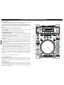 4
4
-
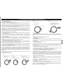 5
5
-
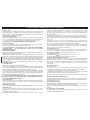 6
6
-
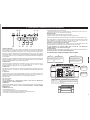 7
7
-
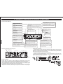 8
8
-
 9
9
-
 10
10
-
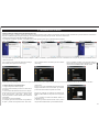 11
11
-
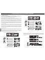 12
12
-
 13
13
-
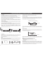 14
14
-
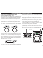 15
15
-
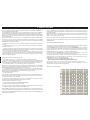 16
16
-
 17
17
-
 18
18
-
 19
19
-
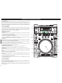 20
20
-
 21
21
-
 22
22
-
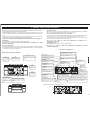 23
23
-
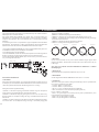 24
24
-
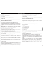 25
25
-
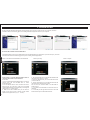 26
26
-
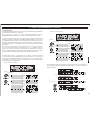 27
27
-
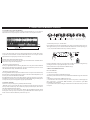 28
28
-
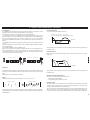 29
29
-
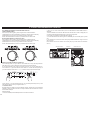 30
30
-
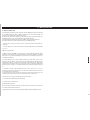 31
31
-
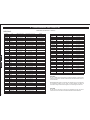 32
32
-
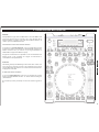 33
33
-
 34
34
-
 35
35
-
 36
36


En otros idiomas
- English: Akiyama K2 User manual
Documentos relacionados
-
Akiyama KURO Manual de usuario
-
-
-
-
-
-
-
-
-
Otros documentos
-
 HQ Power VDSCD3000 Manual de usuario
-
BEGLEC TMC 200 El manual del propietario
-
Gemini CDJ-600 Manual de usuario
-
-
-
-
-
-
-
Numark Total Control Guía de inicio rápido
