La página se está cargando...

AMD INTEL
Quick User Guide
2
Installation Guide
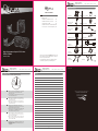
1. Install the fan and radiator in the case
PB120 PB240
1-1 Secure the fan to the radiator with 4
#6-32*29.5mm screws.
1-2 Secure installed radiator in the case with 4
#6-32*6mm screws.
1-1 Fixez le ventilateur au radiateur à I’aide des 4
vis 6-32*29.5mm.
1-2 Fixez I’ensemble radiateur au boîtier à I’aide
des 4 vis 6-32*6mm.
1-1 Befestigen Sie den Lüfter mit 4 Schrauben
(6-32x29.5mm) am Kühlkörper.
1-2 Befestigen Sie den im Gehäuse installierten
Kühlkörper mit 4 Schrauben (6-32x6mm).
1-1 Fije el ventilador en el radiador con 4 tornillos
#6-32 de 29.5 mm.
1-2 Fije el radiador instalado en la carcasa con 4
tornillos #6-32 de 6 mm.
1-1 取4PCS #6-32*29.5mm風扇螺絲,將風扇固定在
水冷排上。
1-2 取4PCS #6-32*6mm水冷排螺絲將已裝好風扇的
水冷排固定在主機殼上。
1-1 Secure fans on radiator with 8 #6-32*29.5mm
screws.
1-2 Secure installed radiator in the case with 8
#6-32*6mm screws.
1-1 Fixez le ventilateur au radiateur à I’aide des 8 vis
6-32*29.5mm.
1-2 Fixez I’ensemble radiateur au boîtier à I’aide des
8 vis 6-32*6mm.
1-1 Befestigen Sie den Lüfter mit 8 Schrauben
(6-32x29.5mm) am Kühlkörper.
1-2 Befestigen Sie den im Gehäuse installierten
Kühlkörper mit 8 Schrauben (6-32x6mm).
1-1 Fije el ventilador en el radiadoer con 8 tornillos
#6-32 de 29.5 mm.
1-2 Fije el radiador instalado en la carcasa con 8
tornillos #6-32 de 6 mm.
1-1 取8PCS #6-32*29.5mm風扇螺絲,將風扇固定在水冷
排上。
1-2 取8PCS #6-32*6mm水冷排螺絲將已裝好風扇的水冷
排固定在主機殼上。
6-32*6
Radiator Screws
6-32*29.5
Fan Screws
6-32*29.5
Fan Screws
6-32*6
Radiator Screws
3
2. Installation Instructions for LGA 2011
2-1 Conrm the motherboard is LGA 2011 platform.
2-2 Secure 4 LGA 2011 screws into the correspond-
ing screw holes.
2-3 Apply a proper amount of the thermal grease on
CPU.
2-4 Tear the protector off from the bottom of water
block and place the installed water block steady
with buckle and LGA 2011 screws on the cut-out
of the motherboard.
2-5 Keep the copper bass plate touching the CPU as
much as possible and secure water block
temperately on top of LGA 2011 screws with 4.
4
3. Install water block
of AMD
3-1 Find the correct AMD buckle as the gure shows.
3-2 Push buckle straight through the cut-out to
bottom without obligating securing.
3-1 Installation du bloc refroidissement à eau
pour un processeur AMD Trouvez la boucle
AMD appropriée comme illustré à la gure.
3-2 Insérez la boucle directement à travers
l’encadrement sans obligation de xation.
3-1 Suchen Sie wie in Abbildung gezeigt nach der
richtigen AMD-Klemme.
3-2 Drücken Sie die Klemme gerade durch die
Aussparung bis zur Unterseite; sie muss nicht
gesichert werden.
3-1 Encuentre el depósito de AMD correcto tal y
como muestra la gura.
3-2 Empuje el depósito sin torcerlo a través del
recorte hasta la parte inferior hasta que
quede jado.
3-1 確認主機板AMD型號選擇對應的扣具,按照上圖
安裝。
3-2 扣具無需螺絲固定,直接將扣具沿扣具卡槽推入到
底即可。
EN
FR
DE
ES
CN
EN
FR
DE
ES
CN
EN
2-1 Fixez les 4 vis du LGA 2011 dans les trous de vis
correspondants.
2-2 Insérez la boucle directement à travers l’encadre-
ment sans obligation de xation.
2-3 Mettez la quantité de graisse thermique
nécessaire sur le CPU.
2-4 Détachez le protecteur situé en bas du bloc
refroidissement à eau et le xer fermement avec
les vis de la boucle et du LGA 2011 sur l’encadre-
ment de la carte mère.
2-5 Maintenez la plaque de base en cuivre en contact
avec le CPU et xez le bloc refroidissement à eau
au-dessus du LGA 2011 avec les 4 vis à ressort.
FR
DE
EN
FR
DE
ES
CN
Buckle
cut-out
INTEL Clip
(Pre-installed)
Spring screws
CPU
LGA 2011
screws
Motherboard
High Performance Liquid CPU Cooler
PB120 / PB240
65 7
Quick User Guide
Installation Guide
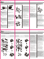
4. Installation Instructions for AMD and INTEL
4-1 確認主機板型號選擇相對應的背板 (Back plate)
AMD/ INTEL面。
4-2 確認主機板的孔位,將4PCS螺杆(M3.5*31screws)
分別插入背板相對應的孔位需注意孔位與螺杆的防
呆卡位。
4-3 將插好螺杆的背板裝至主機板背面在主機板正面分
別裝入4PCS支柱 (Stand-off) 固定背板不掉落。
4-4 在CPU表面均勻塗抹適量的導熱膏。
4-5 將水冷頭銅底上的保護貼紙撕開,將裝好扣具的
水冷頭與已固定的螺杆相對應裝入,水冷頭保持
平放。
4-6 取4PCS彈簧螺母分別鎖至螺杆上固定水冷頭,確
保銅底貼緊CPU表面,彈簧螺母鎖入緊度適中。
4-1 Conrm the motherboard and match the correct
side of back plate (AMD/ INTEL).
4-2 Find the screw holes and secure 4 M3.5*31
screws in. kindly note the scramble of
dummy-proof between stand-off and M3.5*31
screws.
4-3 Insert the installed back plate on the back of the
motherboard and secure the stand-off from the
other side.
4-4 Apply a proper amount of the thermal grease on
CPU.
4-5 Tear the protector off from the bottom of the
water block and place the installed water block
steady with buckle and M3.5*31 screws on the
cut-out of motherboard.
4-6 Keep the copper bass plate touching the CPU as
much as possible and secure water block temperate-
ly on top of M3.5*31 screws with 4 spring screws.
4-1 Trouvez la carte mère et la plaque arrière AMD/
INTEL.
4-2 Trouvez les trous de vis et xez 4 vis M3.5*31
dans Veuillez respecter l’écart de détrompage et
la distance de sécurité des vis M3.5*31.
4-3 Insérez la plaque arrière installée au dos de la
carte mère et la xer de l’autre côté.
4-4 Mettez la quantité de graisse thermique
nécessaire sur le CPU.
4-5 Détachez le protecteur situé en bas du bloc
refroidissement à eau et le xer fermement avec
les vis de la boucle et du M3.5*31 sur l’encadre-
ment de la carte mère.
4-6 Maintenez la plaque de base en cuivre en contact
avec le CPU et xez le bloc refroidissment à eau
au-dessus du M3.5*31 avec les 4 vis à ressort.
4-1 Wählen Sie das richtige Motherboard und die
richtige Rückwand von AMD/ INTEL.
4-2 Suchen Sie nach den Schraubenlöchern und
drehen Sie 4 Schrauben (M3.5 x 31) hinein
Beachten Sie das narrensichere System zwischen
Abstandhalter und Schrauben (M3.5 x 31).
4-3 Stecken Sie die installierte Rückplatte an der
Rückseite des Motherboards hinein und
befestigen Sie Abstandhalter von der anderen
Seite.
4-1 Encuentre la placa base y la placa posterior
de AMD/ INTEL correctas.
4-2 Encuentre los oricios de los tornillos y je
los 4 tornillos M3.5*31. Tenga en cuenta la
separación entre el separador y los tornillos
M3.5*31.
4-3 Inserte la placa posterior instalada en la parte
posterior de la placa base y fije el separador
desde el otro lado.
4-4 Aplique una cantidad de grasa térmica
correcta en la CPU.
4-5 Quite el protector de la parte inferior del
bloque de agua y coloque el bloque de agua
instalado estable con el depósito y los tornillos
M3.5*31 en el recorte de la placa base.
4-6 Mantenga la placa de cobre tocando la PCU
tanto como sea posible y fije el bloque de
agua temporalmente en la parte superior de
los tornillos M3.5*31 con 4 tornillos con muelle.
EN
FR
DE
4-4 Tragen Sie eine geeignete Menge Wärmeleit-
paste auf die CPU auf.
4-5 Lösen Sie die Schutzfolie von der Unterseite
des Wasserblocks und platzieren Sie den
installierten Wasserblock mit der Klemme und
den Schrauben (M3.5 x 31) in der Aussparung
des Motherboards.
4-6 Achten Sie darauf, dass Kupfer-Mess-
ing-Platte und CPU möglichst in Kontakt
stehen; sichern Sie den Wasserblock
vorübergehend mit 4 Federschrauben auf der
Oberseite der Schrauben (M3.5 x 31).
DE
ES
CN
Dummy-proof
PB120 / PB240
High Performance Liquid CPU Cooler
2-1 Suchen Sie den richtigen LGA 2011-CPU-Kontakt
am Motherboard.
2-2 Befestigen Sie 4 LGA 2011-Schrauben in den
entsprechenden Schraubenlöchern.
2-3 Tragen Sie eine geeignete Menge Wärmeleitpaste
auf die CPU auf.
2-4 Quite el protector de la parte inferior del bloque
de agua y coloque el bloque de agua instalado
estable con el depósito y tornillos LGA 2011 en el
recorte de la placa base.
2-5 Mantenga la placa de cobre tocando la CPU
tanto como sea posible y je el bloque de agua
temporalmente en la parte superior de los
tornillos LGA 2011 con 4 tornillos.
2-1 Encuentre la place base LGA 2011 CPU PIN
correcta.
2-2 Fije los 4 tornillos LGA 2011 en los oricios de los
tornillos correspondientes.
2-3 Aplicar una cantidad de grasa térmica correcta en
la CPU.
2-4 Quite el protector de la parte inferior del bloque
de agua y coloque el bloque de agua instalado
estable con el depósito y tornillos LGA 2011 en el
recorte de la placa base.
2-5 Mantenga la placa de cobre tocando la CPU
tanto como sea posible y je el bloque de agua
temporalmente en la parte superior de los
tornillos LGA 2011 con 4 tornillos.
2-1 確認主機板為LGA 2011平臺。
2-2 將4PCS雙頭螺絲 (LGA 2011 screws) 分別裝入對應螺
絲孔位。
2-3 在CPU表面均勻塗抹適量的導熱膏。
2-4 將水冷頭銅底上的保護貼紙撕開,將裝好扣具的水冷頭
與已固定的雙頭螺絲相對應裝入,水冷頭保持平放。
2-5 取4PCS彈簧螺母 (Spring screws) 分別鎖至雙頭螺絲上
固定水冷頭,確保銅底貼緊CPU表面,彈簧螺母鎖入緊
度適中。
ES
CN
Dummy-proof
Spring screw
AMD clip
Stand-off cylinder
CPU
Motherboard
Insulating sheet
Backplate gasket
Back plate in AMD side
Back plate screw
Spring screw
INTEL clip
Stand-off cylinder
CPU
Motherboard
Backplate gasket
Back plate in INTEL side
Back plate screw
Buckle
cut-out
AMD Clip
折線
Transcripción de documentos
High Performance Liquid CPU Cooler PB120 / PB240 Quick User Guide Installation Guide 1. Install the fan and radiator in the case PB120 PB240 2. Installation Instructions for LGA 2011 3. Install water block of AMD 6-32*6 Radiator Screws ES EN 6-32*29.5 Fan Screws 6-32*6 Radiator Screws 6-32*29.5 Fan Screws Buckle cut-out EN EN 1-1 Secure fans on radiator with 8 #6-32*29.5mm screws. 1-2 Secure installed radiator in the case with 8 #6-32*6mm screws. 1-1 Secure the fan to the radiator with 4 #6-32*29.5mm screws. 1-2 Secure installed radiator in the case with 4 #6-32*6mm screws. FR INTEL Clip (Pre-installed) FR 2-1 Fixez les 4 vis du LGA 2011 dans les trous de vis correspondants. 2-2 Insérez la boucle directement à travers l’encadrement sans obligation de fixation. 2-3 Mettez la quantité de graisse thermique nécessaire sur le CPU. 2-4 Détachez le protecteur situé en bas du bloc refroidissement à eau et le fixer fermement avec les vis de la boucle et du LGA 2011 sur l’encadrement de la carte mère. 2-5 Maintenez la plaque de base en cuivre en contact avec le CPU et fixez le bloc refroidissement à eau au-dessus du LGA 2011 avec les 4 vis à ressort. FR 1-1 Fixez le ventilateur au radiateur à I’aide des 8 vis 6-32*29.5mm. 1-2 Fixez I’ensemble radiateur au boîtier à I’aide des 8 vis 6-32*6mm. 1-1 Fixez le ventilateur au radiateur à I’aide des 4 vis 6-32*29.5mm. 1-2 Fixez I’ensemble radiateur au boîtier à I’aide des 4 vis 6-32*6mm. DE LGA 2011 screws 1-1 Befestigen Sie den Lüfter mit 8 Schrauben (6-32x29.5mm) am Kühlkörper. 1-2 Befestigen Sie den im Gehäuse installierten Kühlkörper mit 8 Schrauben (6-32x6mm). 1-1 Befestigen Sie den Lüfter mit 4 Schrauben (6-32x29.5mm) am Kühlkörper. 1-2 Befestigen Sie den im Gehäuse installierten Kühlkörper mit 4 Schrauben (6-32x6mm). ES CPU Motherboard DE 1-1 Fije el ventilador en el radiadoer con 8 tornillos #6-32 de 29.5 mm. 1-2 Fije el radiador instalado en la carcasa con 8 tornillos #6-32 de 6 mm. CN CN 1-1 取4PCS #6-32*29.5mm風扇螺絲,將風扇固定在 水冷排上。 1-2 取4PCS #6-32*6mm水冷排螺絲將已裝好風扇的 水冷排固定在主機殼上。 AMD Clip 2-1 確認主機板為LGA 2011平臺。 2-2 將4PCS雙頭螺絲 (LGA 2011 screws) 分別裝入對應螺 絲孔位。 2-3 在CPU表面均勻塗抹適量的導熱膏。 2-4 將水冷頭銅底上的保護貼紙撕開,將裝好扣具的水冷頭 與已固定的雙頭螺絲相對應裝入,水冷頭保持平放。 2-5 取4PCS彈簧螺母 (Spring screws) 分別鎖至雙頭螺絲上 固定水冷頭,確保銅底貼緊CPU表面,彈簧螺母鎖入緊 度適中。 1-1 取8PCS #6-32*29.5mm風扇螺絲,將風扇固定在水冷 排上。 1-2 取8PCS #6-32*6mm水冷排螺絲將已裝好風扇的水冷 排固定在主機殼上。 2 EN FR DE 2-1 Suchen Sie den richtigen LGA 2011-CPU-Kontakt am Motherboard. 2-2 Befestigen Sie 4 LGA 2011-Schrauben in den entsprechenden Schraubenlöchern. 2-3 Tragen Sie eine geeignete Menge Wärmeleitpaste auf die CPU auf. 2-4 Quite el protector de la parte inferior del bloque de agua y coloque el bloque de agua instalado estable con el depósito y tornillos LGA 2011 en el recorte de la placa base. 2-5 Mantenga la placa de cobre tocando la CPU tanto como sea posible y fije el bloque de agua temporalmente en la parte superior de los tornillos LGA 2011 con 4 tornillos. Spring screws Buckle cut-out CN DE ES 1-1 Fije el ventilador en el radiador con 4 tornillos #6-32 de 29.5 mm. 1-2 Fije el radiador instalado en la carcasa con 4 tornillos #6-32 de 6 mm. 2-1 Encuentre la place base LGA 2011 CPU PIN correcta. 2-2 Fije los 4 tornillos LGA 2011 en los orificios de los tornillos correspondientes. 2-3 Aplicar una cantidad de grasa térmica correcta en la CPU. 2-4 Quite el protector de la parte inferior del bloque de agua y coloque el bloque de agua instalado estable con el depósito y tornillos LGA 2011 en el recorte de la placa base. 2-5 Mantenga la placa de cobre tocando la CPU tanto como sea posible y fije el bloque de agua temporalmente en la parte superior de los tornillos LGA 2011 con 4 tornillos. 2-1 Confirm the motherboard is LGA 2011 platform. 2-2 Secure 4 LGA 2011 screws into the corresponding screw holes. 2-3 Apply a proper amount of the thermal grease on CPU. 2-4 Tear the protector off from the bottom of water block and place the installed water block steady with buckle and LGA 2011 screws on the cut-out of the motherboard. 2-5 Keep the copper bass plate touching the CPU as much as possible and secure water block temperately on top of LGA 2011 screws with 4. ES CN 3 3-1 Find the correct AMD buckle as the figure shows. 3-2 Push buckle straight through the cut-out to bottom without obligating securing. 3-1 Installation du bloc refroidissement à eau pour un processeur AMD Trouvez la boucle AMD appropriée comme illustré à la figure. 3-2 Insérez la boucle directement à travers l’encadrement sans obligation de fixation. 3-1 Suchen Sie wie in Abbildung gezeigt nach der richtigen AMD-Klemme. 3-2 Drücken Sie die Klemme gerade durch die Aussparung bis zur Unterseite; sie muss nicht gesichert werden. 3-1 Encuentre el depósito de AMD correcto tal y como muestra la figura. 3-2 Empuje el depósito sin torcerlo a través del recorte hasta la parte inferior hasta que quede fijado. 3-1 確認主機板AMD型號選擇對應的扣具,按照上圖 安裝。 3-2 扣具無需螺絲固定,直接將扣具沿扣具卡槽推入到 底即可。 4 High Performance Liquid CPU Cooler PB120 / PB240 Quick User Guide Installation Guide 4. Installation Instructions for AMD and INTEL AMD INTEL 4-1 Confirm the motherboard and match the correct side of back plate (AMD/ INTEL). 4-2 Find the screw holes and secure 4 M3.5*31 screws in. kindly note the scramble of dummy-proof between stand-off and M3.5*31 screws. 4-3 Insert the installed back plate on the back of the motherboard and secure the stand-off from the other side. 4-4 Apply a proper amount of the thermal grease on CPU. 4-5 Tear the protector off from the bottom of the water block and place the installed water block steady with buckle and M3.5*31 screws on the cut-out of motherboard. 4-6 Keep the copper bass plate touching the CPU as much as possible and secure water block temperately on top of M3.5*31 screws with 4 spring screws. Spring screw Spring screw AMD clip INTEL clip Stand-off cylinder Stand-off cylinder 4-4 Tragen Sie eine geeignete Menge Wärmeleitpaste auf die CPU auf. 4-5 Lösen Sie die Schutzfolie von der Unterseite des Wasserblocks und platzieren Sie den installierten Wasserblock mit der Klemme und den Schrauben (M3.5 x 31) in der Aussparung des Motherboards. 4-6 Achten Sie darauf, dass Kupfer-Messing-Platte und CPU möglichst in Kontakt stehen; sichern Sie den Wasserblock vorübergehend mit 4 Federschrauben auf der Oberseite der Schrauben (M3.5 x 31). ES 4-1 Encuentre la placa base y la placa posterior de AMD/ INTEL correctas. 4-2 Encuentre los orificios de los tornillos y fije los 4 tornillos M3.5*31. Tenga en cuenta la separación entre el separador y los tornillos M3.5*31. 4-3 Inserte la placa posterior instalada en la parte posterior de la placa base y fije el separador desde el otro lado. 4-4 Aplique una cantidad de grasa térmica correcta en la CPU. 4-5 Quite el protector de la parte inferior del bloque de agua y coloque el bloque de agua instalado estable con el depósito y los tornillos M3.5*31 en el recorte de la placa base. 4-6 Mantenga la placa de cobre tocando la PCU tanto como sea posible y fije el bloque de agua temporalmente en la parte superior de los tornillos M3.5*31 con 4 tornillos con muelle. FR 4-1 Trouvez la carte mère et la plaque arrière AMD/ INTEL. 4-2 Trouvez les trous de vis et fixez 4 vis M3.5*31 dans Veuillez respecter l’écart de détrompage et la distance de sécurité des vis M3.5*31. 4-3 Insérez la plaque arrière installée au dos de la carte mère et la fixer de l’autre côté. 4-4 Mettez la quantité de graisse thermique nécessaire sur le CPU. 4-5 Détachez le protecteur situé en bas du bloc refroidissement à eau et le fixer fermement avec les vis de la boucle et du M3.5*31 sur l’encadrement de la carte mère. 4-6 Maintenez la plaque de base en cuivre en contact avec le CPU et fixez le bloc refroidissment à eau au-dessus du M3.5*31 avec les 4 vis à ressort. CPU CPU Motherboard Motherboard Insulating sheet DE EN Backplate gasket Backplate gasket Back plate in INTEL side Back plate in AMD side Back plate screw CN 4-1 確認主機板型號選擇相對應的背板 (Back plate) AMD/ INTEL面。 4-2 確認主機板的孔位,將4PCS螺杆(M3.5*31screws) 分別插入背板相對應的孔位需注意孔位與螺杆的防 呆卡位。 4-3 將插好螺杆的背板裝至主機板背面在主機板正面分 別裝入4PCS支柱 (Stand-off) 固定背板不掉落。 4-4 在CPU表面均勻塗抹適量的導熱膏。 4-5 將水冷頭銅底上的保護貼紙撕開,將裝好扣具的 水冷頭與已固定的螺杆相對應裝入,水冷頭保持 平放。 4-6 取4PCS彈簧螺母分別鎖至螺杆上固定水冷頭,確 保銅底貼緊CPU表面,彈簧螺母鎖入緊度適中。 Back plate screw DE 4-1 Wählen Sie das richtige Motherboard und die richtige Rückwand von AMD/ INTEL. 4-2 Suchen Sie nach den Schraubenlöchern und drehen Sie 4 Schrauben (M3.5 x 31) hinein Beachten Sie das narrensichere System zwischen Abstandhalter und Schrauben (M3.5 x 31). 4-3 Stecken Sie die installierte Rückplatte an der Rückseite des Motherboards hinein und befestigen Sie Abstandhalter von der anderen Seite. Dummy-proof Dummy-proof 5 6 7-
 1
1
-
 2
2


Rosewill PB120 CPU Liquid Cooler Manual de usuario
- Tipo
- Manual de usuario
- Este manual también es adecuado para
en otros idiomas
Otros documentos
-
Hummer H-240AURA Manual de usuario
-
SilverStone NT06-Pro El manual del propietario
-
Akasa Venom A10 Manual de usuario
-
Corsair HYDRO Series H100i RGB PLATINUM SE Extreme Performance 240mm RGB Liquid CPU Cooler Manual de usuario
-
-
Corsair H115i Guía de inicio rápido
-
-
-
-