
INSTALLATION INSTRUCTIONS
Verand
a
®
Gate Kit
For use with Traditional, Williamsburg
and Pro Rail
BOM-34107834
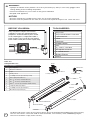
Read all instructions prior to installing product.
Refer to manufacturers safety instructions when operating any tools.
To register your product, please visit:
To register your product, please visit:
veranda.barretteoutdoorliving.com
• English ..............................................................................1
• Español ...........................................................................13

2
Vinyl Rail
Vinyl Rail Brackets & Screws
Tape Measure
Level
Hacksaw
Rubber Mallet
Drill
5
⁄
5
⁄
5
32
⁄32⁄
" and
1
⁄
1
⁄
1
8
⁄8⁄
" Drill Bits
#2 Square Drive Bit
3" Wood Blocks
Safety Glasses
Pencil
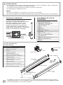
TOOLS NEEDED:
WARNING:
• Improper installation of this product can result in personal injury. Always wear safety goggles when
cutting, drilling and assembling the product.
• Incorrect installation may cause harm to the gate or individual.
• Not pool code approved.
NOTICE:
• DO NOT attempt to assemble the kit if parts are missing or damaged.
• DO NOT return the product to the store, for assistance or replacement parts call: 1-800-336-2383.
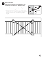
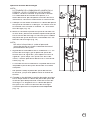
BEFORE YOU BEGIN:
Vinyl rail posts require an internal
support system for weight-bearing
purposes and therefore a post install
kit or wood post is required inside a
post jacket. Post install kit and wood
post needs to be purchased separately.
Top View of Post Jacket
Top View of Post Jacket
Rail
Rail
Purchased
Post Install Kit
Gate Kit
Component list:
QTY Description
2
Vinyl Uprights
2
Aluminum Stiffeners
4
Caps
1
Gravity Latch
6
1" Phillips Screws (For Gravity Latch)
2
Telescoping Metal Braces
4
#8 x
3
⁄
3
⁄
3
4
⁄4⁄
" Screws (For Metal Braces)
4
#8 x
3
⁄
3
⁄
3
8
⁄8⁄
" Screws (For Metal Braces)
4
#10 x 1" Screws (For Bottom Rail Brackets)
2
Compact Butter y Hinges
8
1" Phillips Screws (For Hinges)
1
Allen Wrench (For Hinges)
Gravity Latch
1" Phillips Screws
1" Screws For
Bottom Rail
Brackets
Hinges
Allen Wrench
1" Phillips Screws
Aluminum Stiffeners
Vinyl Upright
Vinyl Upright
Caps
Caps
Screws For Metal Braces
Metal Braces
To obtain and review a copy of the warranty please go to: Veranda.BarretteOutdoorLiving.com/warranty.
You can also contact 1-877-279-4496 or write to Veranda, 7830 Freeway Circle, Middleburg Heights,
Ohio 44130 to obtain a copy of the warranty.

3
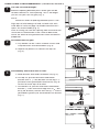
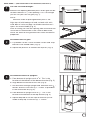
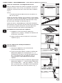
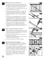
Measure Opening
TRADITIONAL & WILLIAMSBURG -
(FOR PRO RAIL, SEE PAGE 7)
Cut rails to needed length:
Measure opening between posts where gate will be
located. Subtract 6" from opening. This is the length
you will cut your rails for gate (Fig. 1).
NOTE:
Maximum width of opening between posts is 48".
Align top rail with bottom rail and cut both rails with
miter box or hacksaw (See saw blade manufacturer's
specs for correct blade) (Fig. 2).
Prior to cutting, be sure the spacing from the end of the
rail to the rst routed hole is the same on both ends,
which will allow for the gate balusters to be installed in
proportion.
Assemble rails for gate:
a. Lay bottom rail on a clean smooth surface and
snap balusters into routed holes (Fig. 3).
b. Repeat the process to connect the top rail
(Fig. 4).
Permanently attach brackets to rails:
a. Slide brackets onto ends of bottom rail (Fig. 5).
b. For top rail, pre-drill one hole underneath
bracket with a
5
⁄
5
⁄
5
32
⁄32⁄
" drill bit then secure with a 1"
at head screw (provided in bracket kit) (Fig. 6).
Do this for each top rail bracket.
c. For bottom rail, pre-drill two holes underneath
bracket
1
⁄
1
⁄
1
4
⁄4⁄
" back from front edge with a
5
⁄
5
⁄
5
32
⁄32⁄
" drill
bit (2 per bracket). Secure with two (2) 1" screws
(provided in gate kit) for each bottom rail bracket
(Fig. 7).
1
2
3
Fig. 1
Fig. 2
Fig. 3
Fig. 4
Fig. 5
Fig. 6
Fig. 7
Bottom Rail
(Not to Exceed 48")
Top Rail
Bottom Rail
Screw
Screws

4
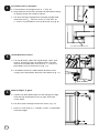
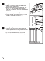
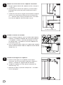
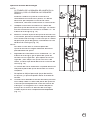
Assemble rails to uprights:
a. From bottom of upright mark at 1" (Fig. 8).
b. Align bottom of bracket (already connected to railing
in step 3a) to the line made in step 4a.
c. Pre-drill through angled holes through upright and
aluminum with
5
⁄
5
⁄
5
32
⁄32⁄
" drill bit. Screw in with four (4)
2" screws as provided in the rail bracket kit (Fig. 9).
Mount hinges to gate:
a. Center the provided hinges on the upright to align
with the top and bottom rails of gate and mark
screw holes.
b. Pre-drill holes through aluminum insert (Fig. 12).
c. Screw in with two (2) 1" Phillips screws as provided
with the hinges.
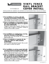
Install Bracket Covers:
a. For top bracket: open the top bracket cover and
wrap it around the top rail and bracket. Pre-drill
and secure underneath with two (2) 1" screws as
provided in the rail bracket kit (Fig. 10).
b. For bottom bracket: slide bottom bracket cover
snugly over the bottom bracket from below (Fig. 11).
4
6
5
1"
Fig. 8
Pre-drill and install screws
Fig. 9
Fig. 10
Fig. 11
Fig. 12

5
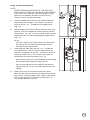
Hinge Tension Adjustment
NOTE:
HINGE TENSION IS PRE-SET AT THE FACTORY
AND USUALLY
DOES NOT REQUIRE ADJUSTMENT.
If you wish to change tension setting/gate swing
speed, or completely disable the self-closing
feature, please see the following:
a. Place included allen wrench into head of tension
adjustment pin in hinge. The head is at the end
closest to the + or - symbol on the hinge barrel
(Fig. 13).
b. While holding the tension adjustment pin with allen
wrench, press the opposite end of the pin into the
hinge barrel. This will cause the head of the tension
adjustment pin to extend beyond the hinge barrel
(Fig. 13).
NOTE:
DO NOT remove the allen wrench or release the
tension on the tension adjustment pin at any
time during the adjustment.
c. Following the indicators on the + or - symbol on
the hinge barrel, turn the tension adjustment pin
toward + to tighten, or toward - to loosen. DO NOT
adjust by more than
1
⁄
1
⁄
1
4
⁄4⁄
turn, unless you want to
disable the self-closing feature (Fig. 13).
- Self-closing feature can be disabled by loosening
the tension adjustment pin one full turn.
- Do not over-tighten or over-loosen the tension
adjustment pin, as this may damage the tension
spring.
d. When you have set the desired tension, press
down on the head of the tension adjustment pin to
lock it back into the hinge barrel. Tabs on pin head
will t into notches in hinge barrel when pin is in
fully locked position (Fig. 14).
Allen Allen
WrenchWrench
Press Up
Press Up
Press Up
Press Up
Press Up
Press Up
Press Up
Press Up
Press Up
Tension
Tension
Tension
Tension
Tension
Tension
Tension
Tension
Tension
Adjustment
Adjustment
Adjustment
Adjustment
Adjustment
Adjustment
Adjustment
Adjustment
Adjustment
Adjustment
Adjustment
Adjustment
Adjustment
Adjustment
Pin
Pin
Pin
Pin
Fig. 13
Press Down
Press Down
Press Down
Press Down
Press Down
Press Down
Press Down
Press Down
Press Down
Press Down
Press Down
Press Down
Press Down
Press Down
Press Down
Press Down
Press Down
Press Down
Press Down
Fig. 14

6
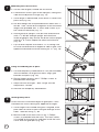
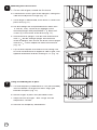
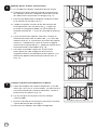
Mounting the cross braces:
a. On one side of gate, extend the rst brace.
b. Extend brace across gate to the uprights, noting one
side will be adjacent to hinge (Fig. 15).
c. Once length is determined, mark brace in center with
pencil line (Fig. 16).
d. Pre-drill though the two provided brace holes with
1
⁄
1
⁄
1
8
⁄8⁄
"
drill bit. Then, secure brace together at the measured
length with provided #8 x
3
⁄
3
⁄
3
8
⁄8⁄
" blunt end screws (2) in
the center of the brace (Fig. 17).
e. Attach brace to uprights. Pre-drill one end of brace
with a
1
⁄
1
⁄
1
8
⁄8⁄
" drill bit through upright and aluminum
inside of upright, then anchor the brace to the upright
with #8 x
3
⁄
3
⁄
3
4
⁄4⁄
" screw. Repeat for other end of brace
(Fig. 18).
f. Flip rail over. Repeat instructions 7a–7e, being sure
to install second brace on opposite side of gate, and
opposite orientation of brace making an "X" (Fig. 19).
Hang assembled gate to post:
a. Cut two temporary wood blocks 3" tall (not included),
and rest bottom rail of gate on them. Align gate
between the posts (Fig. 19).
b. Secure hinges to posts with 1" Phillips screws as
provided with the hinges.
c. Adjust tension of hinges – See "Hinge Tension
Adjustment" section.
d. Remove the temporary wood blocks.
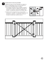
Install gravity latch:
Orient the latch at desired height on gate/post. Latch
should be on same side of gate, opposite of hinges.
a. Once hinges are installed and gate is aligned, mark
pilot holes for latch on post and gate through screw
holes. Then drill using
3
⁄
3
⁄
3
32
⁄32⁄
" bit.
b. Measure and install latch with six (6) 1" Phillips
screws as provided with the latch. The latch striker
is installed on the gate rst and then install the latch
catch onto the gate post (Fig. 20).
7
8
9
Fig. 15
Fig. 16
Fig. 17
Fig. 18
Fig. 19
3" Spacer Blocks
3" Spacer Blocks
Gate Post
Gate
Fig. 20
Latch Striker
Latch Striker
Latch Striker
Latch Striker
Latch Catch

7
Measure Opening
Cut rails to needed length:
Measure the opening between posts where gate will be
located. Subtract 5
1
⁄
1
⁄
1
2
⁄2⁄
" from opening. This is the length
you will cut your rails for gate (Fig. 1).
NOTE:
Maximum width of opening between posts is 48".
Align top rail with bottom rail and cut both rails with
miter box or hacksaw (See saw blade manufacturer's
specs for correct blade) (Fig. 2).
Prior to cutting, be sure the spacing from the end of the
rail to the rst routed hole is the same on both ends,
which will allow for the gate balusters to be installed in
proportion.
Assemble rails for gate:
a. Lay bottom rail on a clean smooth surface and snap
balusters into routed holes (Fig. 3).
b. Repeat the process to connect the top rail. (Fig. 4)
Assemble brackets to uprights:
a. From bottom of upright mark at
1
⁄
1
⁄
1
2
⁄2⁄
". This is the
location of the bottom of the bottom bracket (Fig. 5).
b. Align bottom of bracket to this line (Fig. 6).
c. Pre-drill holes through upright and aluminum with
5
⁄
5
⁄
5
32
⁄32⁄
"
drill bit. Screw in with two (2) 1" screws as provided
in the rail bracket kit (Fig. 6).
d. From bottom of upright mark 32
1
⁄
1
⁄
1
16
⁄16⁄
". This is the
location of the bottom of the top bracket (Fig. 5).
e. Repeat Step 3b-3c for the top rail bracket (at line
made in Step 3d). Install two (2) 1" screws.
1
2
3
PRO RAIL -
(FOR TRADITIONAL & WILLIAMSBURG, SEE PAGE 3)
(Not to exceed 48")
Fig. 1
Fig. 2
Fig. 3
Fig. 4
Fig. 5
Fig. 6
32
32
1
⁄
⁄
⁄
1
⁄
1
⁄
16
"
1
1
⁄
⁄
⁄
1
⁄
1
⁄
2
⁄2⁄
2
"
1
1
⁄
⁄
⁄
1
⁄
1
⁄
2
⁄2⁄
2
"

8
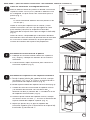
Permanently attach rails to brackets
on the uprights:
a. Add the assembled rail section from Step 2 to the
brackets on the uprights (Fig. 7).
b. Making sure the uprights are ush to the rails, pre-
drill with a
5
⁄
5
⁄
5
32
⁄32⁄
" drill bit through the bracket holes
under rails
(3 per bracket). Do for both top and bottom
rails (Fig. 7).
c. Attach brackets to the rails, using 1" screws
(provided in rail kit) (3 per bracket).
d. Optional "gaskets" are included in each rail bracket
kit and can be installed if desired (Fig. 8).
Mount hinges to gate:
a. Center the provided hinges on the upright to align
with the top and bottom rails of gate and mark screw
holes.
b. Pre-drill holes through aluminum insert (Fig. 9).
c. Screw in with two screws (provided with hinge)
4
5
Fig. 7
Fig. 8
Fig. 9
Gasket
Gasket
Gasket
Gasket

9
Hinge Tension Adjustment
NOTE:
HINGE TENSION IS PRE-SET AT THE FACTORY
AND USUALLY
DOES NOT REQUIRE ADJUSTMENT.
If you wish to change tension setting/gate swing
speed, or completely disable the self-closing
feature, please see the following:
a. Place included allen wrench into head of tension
adjustment pin in hinge. The head is at the end
closest to the + or - symbol on the hinge barrel
(Fig. 10).
b. While holding the tension adjustment pin with allen
wrench, press the opposite end of the pin into the
hinge barrel. This will cause the head of the tension
adjustment pin to extend beyond the hinge barrel
(Fig. 10).
NOTE:
DO NOT remove the allen wrench or release the
tension on the tension adjustment pin at any
time during the adjustment.
c. Following the indicators on the + or - symbol on
the hinge barrel, turn the tension adjustment pin
toward + to tighten, or toward - to loosen. DO NOT
adjust by more than
1
⁄
1
⁄
1
4
⁄4⁄
turn, unless you want to
disable the self-closing feature (Fig. 10).
- Self-closing feature can be disabled by loosening
the tension adjustment pin one full turn.
- Do not over-tighten or over-loosen the tension
adjustment pin, as this may damage the tension
spring.
d. When you have set the desired tension, press
down on the head of the tension adjustment pin to
lock it back into the hinge barrel. Tabs on pin head
will t into notches in hinge barrel when pin is in
fully locked position (Fig. 11).
Allen Allen
WrenchWrench
Press Up
Press Up
Press Up
Press Up
Press Up
Press Up
Press Up
Press Up
Press Up
Tension
Tension
Tension
Tension
Tension
Tension
Tension
Tension
Tension
Adjustment
Adjustment
Adjustment
Adjustment
Adjustment
Adjustment
Adjustment
Adjustment
Adjustment
Adjustment
Adjustment
Adjustment
Adjustment
Adjustment
Pin
Pin
Pin
Pin
Fig. 10
Press Down
Press Down
Press Down
Press Down
Press Down
Press Down
Press Down
Press Down
Press Down
Press Down
Press Down
Press Down
Press Down
Press Down
Press Down
Press Down
Press Down
Press Down
Press Down
Fig. 11

10
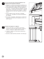
Mounting the cross braces:
a. On one side of gate, extend the rst brace.
b. Extend brace across gate to the uprights, noting one
side will be adjacent to hinge (Fig. 11).
c. Once length is determined, mark brace in center with
pencil line (Fig. 11).
d. Pre-drill though the two provided brace holes with
1
⁄
1
⁄
1
8
⁄8⁄
" drill bit. Then, secure brace together at the
measured length with provided #8 x
3
⁄
3
⁄
3
8
⁄8⁄
" blunt end
screws (2) in the center of the brace (Fig. 12).
e. Attach brace to uprights. Pre-drill one end of brace
with a
1
⁄
1
⁄
1
8
⁄8⁄
" drill bit through upright and aluminum
inside of upright, then anchor the brace to the upright
with #8 x
3
⁄
3
⁄
3
4
⁄4⁄
" screw. Repeat for other end of brace
(Fig. 13).
f. Flip rail over. Repeat instructions 6a–6e, being sure
to install second brace on opposite side of gate, and
opposite orientation of brace making an "X" (Fig. 14).
Hang assembled gate to post:
a. Cut two temporary wood blocks 3" tall (not included),
and rest bottom rail of gate on them. Align gate
between the posts (Fig. 15).
b. Secure hinges to posts with provided screws.
c. Adjust tension of hinges – See "Hinge Tension
Adjustment" section.
d. Remove the temporary wood blocks.
6
7
Fig. 11
Fig. 12
Fig. 13
Fig. 14
3" Temporary spacer blocks
Fig. 15

11
Install gravity latch:
Orient the latch at desired height on gate/post. Latch
should be on same side of gate, opposite of hinges.
a. Once hinges are installed and gate is aligned, mark
pilot holes for latch on post and gate through screw
holes. Then drill using
3
⁄
3
⁄
3
32
⁄32⁄
" bit.
b. Measure and install latch with six (6) 1" Phillips screws
provided. The latch striker is installed on the gate rst
and then install the latch catch onto the gate post
(Fig. 16).
8
Gate Post
Gate
Fig. 16
Latch Striker
Latch Striker
Latch Striker
Latch Striker
Latch Catch

12

INSTRUCCIONES DE INSTALACIÓN
Kit de puerta Verand
a
®
Para su uso con Traditional, Williamsburg
y Pro Rail
BOM-34107834
Lea todas las instrucciones antes de instalar el producto
Consulte las instrucciones de seguridad del fabricante al utilizar herramientas
Para registrar su producto, visite:
Para registrar su producto, visite:
veranda.barretteoutdoorliving.com
• English ..............................................................................1
• Español ...........................................................................13

14
Travesaño de vinilo
Soportes y tornillos del
travesaño de vinilo
Cinta métrica
Nivel
Segueta
Martillo de goma
Taladro
Brocas de
5
⁄
5
⁄
5
32
⁄32⁄
" y
1
⁄
1
⁄
1
8
⁄8⁄
"
Punta de destornillador
cuadrado #2
Bloques de madera de 7.6 cm (3")
Gafas de protección
Lápiz
HERRAMIENTAS QUE SE
REQUIEREN:
ADVERTENCIA:
• La instalación incorrecta de este producto puede resultar en lesiones corporales. Utilice siempre gafas
de seguridad al cortar, taladrar y ensamblar el producto.
• La instalación incorrecta puede causar daños a la puerta o a personas.
• No aprobado por el código de piscinas
AVISO:
• NO intente ensamblar el kit si faltan piezas o las piezas están dañadas.
• NO devuelva el producto a la tienda; para solicitar ayuda o piezas de repuesto, llame al: 1-800-336-2383.
ANTES DE COMENZAR:
Los postes del barandal de vinilo
requieren un sistema de soporte interno
para poder soportar el peso y, por
lo tanto, es necesario usar un kit de
instalación de postes o un poste de
madera dentro de la funda de poste. El
kit de instalación de postes y el poste de
madera se compran por separado.
Vista superior de la funda de poste
Vista superior de la funda de poste
Travesaño
Travesaño
Travesaño
Travesaño
Travesaño
Travesaño
Travesaño
Travesaño
Travesaño
Travesaño
Travesaño
Comprado
Kit de
instalación de
poste
Lista de componentes
del kit de puerta:
QTY Description
2
Soportes verticales de vinilo
2
Refuerzos de aluminio
4
Tapones
1
Cerrojo de gravedad
6
Tornillos phillips de 1"
(para el cerrojo de gravedad)
2
Abrazaderas metálicas telescópicas
4
Tornillos #8 de
3
⁄
3
⁄
3
4
⁄4⁄
"
(para las abrazaderas metálicas)
4
Tornillos #8 de
3
⁄
3
⁄
3
8
⁄8⁄
"
(para las abrazaderas metálicas)
4
Tornillos #10 de 1"
(para los soportes de travesaño inferior)
2
Bisagras de mariposa compactas
8
Tornillos phillips de 1" (para las bisagras)
1
Llave allen (para las bisagras)
Cerrojo de gravedad
Tornillos Phillips de 1"
Tornillos de 1"
para los soportes
de travesaño
inferior
Bisagras
Llave Allen
Tornillos Phillips de 1"
Refuerzos de aluminio
Soporte vertical
de vinilo
Soporte vertical de
vinilo
Tapones
Caps
Tornillos para
abrazaderas metálicas
Abrazaderas metálicas
Para obtener y revisar una copia de la garantía, vaya a: Veranda.BarretteOutdoorLiving.com/warranty.
También puede llamar al 1-877-279-4496 o escribir a Veranda, 7830 Freeway Circle, Middleburg Heights,
OH 44130 para obtener una copia de la garantía.

15
Mida la abertura
TRADITIONAL Y WILLIAMSBURG -
(PARA PRO RAIL CONSULTE LA PÁGINA 19)
Corte los travesaños a la longitud necesaria:
Mida la abertura entre los postes en donde se instalará
la puerta. Reste 15.25 cm (6") a la abertura. Esta es la
longitud a la que cortará los travesaños para la puerta
(Fig. 1).
NOTA:
El ancho máximo de abertura entre los postes es
de 120 cm (48").
Alinee el travesaño superior con el inferior y corte ambos
travesaños con una caja de ingletes o sierra para metales
(consulte las especi caciones del fabricante de la hoja
de sierra para escoger la indicada) (Fig. 2).
Antes de cortar, compruebe que la distancia desde el
extremo del travesaño hasta el primero ori cio ranurado
es la misma en ambos extremos, lo que le permitirá
instalar los barrotes de la puerta en proporción.
Ensamblar los travesaños de la puerta:
a. Coloque el travesaño inferior sobre una
super cie lisa y limpia y coloque los barrotes en
los ori cios ranurados.
b. Repita el proceso para conectar el travesaño
superior (Fig. 4)
Fije los soporte de modo permanente a
los travesaños:
a. Deslice los soportes en los extremos del
travesaño inferior (Fig. 5).
b. Para el travesaño superior, taladre un ori cio por
debajo del soporte con una broca de
5
⁄
5
⁄
5
32
⁄32⁄
" y, a
continuación, je con un tornillo de cabeza plana
de 1" (incluido en el kit de soportes) (Fig. 6).
Haga esto para cada soporte de travesaño
superior.
c. Para el travesaño inferior, taladre dos agujeros por
debajo del soporte a
1
⁄
1
⁄
1
4
⁄4⁄
" desde el borde delantero
con una broca de
5
⁄
5
⁄
5
32
⁄32⁄
" (dos por soporte). Fije con
dos (2) tornillos de 1" (incluido en el kit de puerta)
para cada soporte de travesaño inferior (Fig. 7).
1
2
3
Fig. 1
Fig. 2
Fig. 3
Fig. 4
Fig. 5
Fig. 6
Fig. 7
Travesaño inferior
(no debe superar los
122 cm o 48")
Travesaño superior
Travesaño inferior
Tornillo
Tornillos

16
Montar los travesaños en los soportes verticales:
a. Desde la parte inferior del soporte vertical, marque a
1" (Fig. 8).
b. Alinee la parte inferior del soporte (ya conectado a
barandilla en el paso 3a) con la línea hecha en el
paso 4a.
c. Taladre los ori cios en ángulo atravesando el soporte
vertical y el refuerzo de aluminio con una broca de
5
⁄
5
⁄
5
32
⁄32⁄
". Atornille con cuatro (4) tornillos de 2" incluidos
en el kit de soportes de travesaños (Fig. 9).
Instalar las bisagras en la puerta:
a. Centre las bisagras en el soporte vertical para
alinearlas con los travesaños de puerta superior e
inferior y marque los agujeros de los tornillos.
b. Taladre los agujeros a través de los refuerzos de
aluminio (Fig. 12).
c. Atornille con dos (2) tornillos Phillips de 1" incluidos
con las bisagras.
Taladre e instale los tornillos
a. Para el soporte superior: abra la cubierta de soporte
superior y enróllelo alrededor del travesaño superior
y el soporte. Taladre y atornille por debajo con dos
(2) tornillos de 1" incluidos en el kit de soportes de
travesaños (Fig. 10).
b. Para el soporte inferior: deslice la cubierta de soporte
inferior perfectamente sobre el soporte inferior desde
abajo (Fig. 11).
4
6
5
1"
Fig. 8
Pre-drill and install screws
Fig. 9
Fig. 10
Fig. 11
Fig. 12

17
Ajuste de tensión de la bisagra
NOTA:
LA TENSIÓN DE LA BISAGRA SE AJUSTA EN LA
FÁBRICA y POR LO GENERAL NO REQUIERE
AJUSTE. Si desea cambiar el ajuste de la tensión
o la velocidad de oscilación de la puerta, o si
desea desactivar por completo la función de cierre
automático, consulte la información a continuación:
a. Coloque la llave Allen incluida en la cabeza del perno
de ajuste de tensión en la bisagra. La cabeza está en
el extremo más cercano al símbolo + o - en el barril
de la bisagra (Fig. 13).
b. Mientras sostiene el perno de ajuste de tensión con
la llave Allen, presione el extremo opuesto del perno
hacia el barril de la bisagra. Esto hará que la cabeza
del perno de ajuste de tensión se extienda más allá
del barril de la bisagra (Fig. 13).
NOTA:
NO retire la llave Allen ni suelte el perno de
ajuste de tensión en ningún momento durante el
procedimiento de ajuste.
c. Siguiendo los indicadores en el símbolo de + o - en
el barril de la bisagra, gire el perno de ajuste de
tensión hacia el signo de + para apretar o hacia el
signo de - para a ojar. NO ajuste más de 1⁄4 de
vuelta, a menos que desee desactivar la función de
cierre (Fig. 13).
- La función de cierre automático se puede desactivar
a ojando el perno de ajuste de tensión una vuelta
completa.
- No apriete o a oje el perno de ajuste de tensión
en exceso, ya que esto podría dañar el resorte de
tensión.
d. Cuando se ha de nido la tensión deseada, presione
hacia abajo sobre la cabeza del perno de ajuste de
la tensión para bloquearlo de vuelta en el barril de
la bisagra. Las lengüetas en la cabeza del perno
encajan en las muescas del barril de la bisagra
cuando el perno está completamente bloqueado
(Fig. 14).
Llave
Llave
AllenAllen
Presione hacia arriba
Presione hacia arriba
Presione hacia arriba
Presione hacia arriba
Presione hacia arriba
Presione hacia arriba
Presione hacia arriba
Presione hacia arriba
Presione hacia arriba
Presione hacia arriba
Presione hacia arriba
Presione hacia arriba
Presione hacia arriba
Presione hacia arriba
Perno de
Perno de
Perno de
Perno de
Perno de
Perno de
Perno de
Perno de
Perno de
ajuste de
ajuste de
ajuste de
ajuste de
ajuste de
ajuste de
ajuste de
ajuste de
ajuste de
tensión
tensión
tensión
tensión
tensión
tensión
tensión
tensión
tensión
tensión
tensión
tensión
tensión
tensión
tensión
tensión
tensión
tensión
Fig. 13
Presione hacia abajo
Presione hacia abajo
Presione hacia abajo
Presione hacia abajo
Presione hacia abajo
Presione hacia abajo
Presione hacia abajo
Presione hacia abajo
Presione hacia abajo
Presione hacia abajo
Presione hacia abajo
Presione hacia abajo
Presione hacia abajo
Presione hacia abajo
Presione hacia abajo
Presione hacia abajo
Presione hacia abajo
Presione hacia abajo
Presione hacia abajo
Presione hacia abajo
Presione hacia abajo
Presione hacia abajo
Presione hacia abajo
Presione hacia abajo
Presione hacia abajo
Presione hacia abajo
Presione hacia abajo
Presione hacia abajo
Presione hacia abajo
Presione hacia abajo
Presione hacia abajo
Presione hacia abajo
Fig. 14

18
Montaje de los tirantes transversales:
a. En un lado de la puerta, extienda el primer tirante.
b. Extienda el tirante a todo lo largo de la puerta hasta
los soportes verticales; tenga en cuenta que uno de
los lados estará adyacente a la bisagra (Fig. 15).
c. Una vez que determine la longitud, marque el tirante
en el centro con un lápiz (Fig. 16).
d. Taladre un agujero a través de los dos ori cios de
tirante provistos con una broca de
1
⁄
1
⁄
1
8
⁄8⁄
". Luego, je
el tirante a la longitud medida con los tornillos de
extremo romo #8 de
3
⁄
3
⁄
3
8
⁄8⁄
" (2) en el centro del tirante
(Fig. 17).
e. Fije el tirante en los soportes verticales. Perfore un
extremo del tirante con una broca de
1
⁄
1
⁄
1
8
⁄8⁄
" a través
del soporte vertical y el aluminio en el interior del
soporte vertical y, a continuación, ancle el tirante al
soporte vertical con el tornillo #8 de
3
⁄
3
⁄
3
4
⁄4⁄
". Repita lo
anterior en el otro extremo de la abrazadera (Fig. 18).
f. Dé vuelta al barandal. Repita las instrucciones
de los pasos 7a a 7e; asegúrese de instalar el
segundo tirante en el lado opuesto de la puerta, y en
orientación opuesta del tirante para formar una "X"
(Fig. 19).
Cuelgue la puerta ensamblada en el poste:
a. Corte dos bloques de madera temporales a una de
altura de 7.62 cm o 3" (no incluidos), y el descanse el
travesaño inferior de la puerta sobre ellos. Alinee la
puerta entre los postes (Fig. 19).
b. Atornille las bisagras con los tornillos Phillips de 1"
incluidos con las bisagras.
c. Ajuste la tensión de las bisagras (consulte la sección
"Ajuste de tensión de la bisagra")
d. Remueva los bloques de madera temporales.
Instalación del cerrojo de gravedad:
Coloque el cerrojo a la altura deseada en la puerta o
poste. El cerrojo debe estar en el mismo lado de la
puerta, en el lado opuesto de las bisagras.
a. Una vez que las bisagras estén instaladas y la puerta
esté alineada, marque los agujeros para el cerrojo en
el poste y en la puerta a través de los agujeros para
tornillos. A continuación, perfore con una broca de
3
⁄
3
⁄
3
32
⁄32⁄
".
b. Mida e instale el cerrojo con los seis (6) tornillos
Phillips de 1" incluidos con el cerrojo. La traba
del cerrojo se instala primero en la puerta y, a
continuación, instale el cerrojo en el poste de la
puerta (Fig. 20).
7
8
9
Fig. 15
Fig. 16
Fig. 17
Fig. 18
Fig. 19
Bloques de madera de 7.6 cm (3")
Poste de
puerta
Puerta
Traba
Cierre
Fig. 20

19
Mida la abertura
Corte los travesaños a la longitud necesaria:
Mida la abertura entre los postes en donde se instalará
la puerta. Reste 14 cm (5 1⁄2") desde la abertura. Esta
es la longitud a la que cortará los travesaños para la
puerta (Fig. 1).
NOTA:
El ancho máximo de abertura entre los postes es de
120 cm (48").
Alinee el travesaño superior con el inferior y corte
ambos travesaños con una caja de ingletes o sierra
para metales (consulte las especi caciones del
fabricante de la hoja de sierra para escoger la indicada)
(Fig. 2).
Antes de cortar, compruebe que la distancia desde el
extremo del travesaño hasta el primero ori cio ranurado
es la misma en ambos extremos, lo que le permitirá
instalar los barrotes de la puerta en proporción.
Ensamblar los travesaños de la puerta:
a. Coloque el travesaño inferior sobre una super cie
lisa y limpia y coloque los barrotes en los ori cios
ranurados.
b. A continuación, repita el proceso para conectar el
travesaño superior. (Fig. 4)
Ensamblar los soportes en los soportes verticales:
a. Desde la parte inferior del soporte vertical, marque
una línea a 1.27 cm o
1
⁄
1
⁄
1
2
⁄2⁄
". Esta es la ubicación de la
parte inferior del soporte inferior (Fig. 5).
b. Alinee la parte inferior del soporte con esta línea (Fig. 6).
c. Taladre los ori cios atravesando el soporte vertical
y el refuerzo de aluminio con una broca de
5
⁄
5
⁄
5
32
⁄32⁄
".
Atornille con dos (2) tornillos de 1" incluidos en el kit
de soportes de travesaños (Fig. 6).
d. Desde la parte inferior del soporte vertical, marque
una línea a 81.44 cm o 32
1
⁄
1
⁄
1
16
⁄16⁄
". Esta es la ubicación de
la parte inferior del soporte superior (Fig. 5).
e. Repita los pasos 3b y 3c para el soporte del
travesaño superior (con la línea hecha en el paso 3d).
Instale dos (2) tornillos de 1".
1
2
3
PRO RAIL -
(PARA LOS MODELOS TRADITIONAL Y WILLIAMSBURG, CONSULTE LA PÁGINA 15)
(no debe superar
los 122 cm o 48")
Fig. 1
Fig. 2
Fig. 3
Fig. 4
Fig. 5
Fig. 6
32
32
1
⁄
⁄
⁄
1
⁄
1
⁄
16
"
1
1
⁄
⁄
⁄
1
⁄
1
⁄
2
⁄2⁄
2
"
1
1
⁄
⁄
⁄
1
⁄
1
⁄
2
⁄2⁄
2
"

20
Fije los travesaños de forma permanente en los
soportes de los soportes verticales:
a. Agregue la sección de travesaño ensamblado en el
paso 2 a los soportes de los soportes verticales (Fig. 7).
b. Compruebe que los soportes verticales queden al
ras con los travesaños, perfore los agujeros con una
broca de
5
⁄
5
⁄
5
32
⁄32⁄
" a través de los ori cios de los soportes
debajo de los travesaños (3 por soporte). Haga lo
mismos para los travesaños superiores e inferiores
(Fig. 7).
c. Fije los soportes en los travesaños, utilizando
tornillos de 1" (incluidos en el kit de travesaños) (3
por soporte).
d. Se incluyen "empaques" opcionales en cada kit de
soporte de travesaños que se pueden instalar si lo
desea (Fig. 8).
Instalar las bisagras en la puerta:
a. Centre las bisagras en el soporte vertical para
alinearlas con los travesaños de puerta superior e
inferior y marque los agujeros de los tornillos.
b. Taladre los agujeros a través de los refuerzos de
aluminio (Fig. 9).
c. Atornille con dos tornillos (incluidos con la bisagra)
4
5
Fig. 7
Fig. 8
Fig. 9
Empaque
Empaque
Empaque
Empaque
Empaque
Empaque
Empaque
Empaque

21
Ajuste de tensión de la bisagra
NOTA:
LA TENSIÓN DE LA BISAGRA SE AJUSTA EN LA
FÁBRICA y POR LO GENERAL NO REQUIERE
AJUSTE.
Si desea cambiar el ajuste de la tensión o la
velocidad de oscilación de la puerta, o si desea
desactivar por completo la función de cierre
automático, consulte la información a continuación:
a. Coloque la llave Allen incluida en la cabeza del
perno de ajuste de tensión en la bisagra. La cabeza
está en el extremo más cercano al símbolo + o - en
el barril de la bisagra (Fig. 10).
b. Mientras sostiene el perno de ajuste de tensión con
la llave Allen, presione el extremo opuesto del perno
hacia el barril de la bisagra. Esto hará que la cabeza
del perno de ajuste de tensión se extienda más allá
del barril de la bisagra (Fig. 10).
NOTA:
NO retire la llave Allen ni suelte el perno de
ajuste de tensión en ningún momento durante el
procedimiento de ajuste.
c. Siguiendo los indicadores en el símbolo de + o - en
el barril de la bisagra, gire el perno de ajuste de
tensión hacia el signo de + para apretar o hacia el
signo de - para a ojar. NO ajuste más de 1⁄4 de
vuelta, a menos que desee desactivar la función de
cierre (Fig. 10).
- La función de cierre automático se puede desactivar
a ojando el perno de ajuste de tensión una vuelta
completa.
- No apriete o a oje el perno de ajuste de tensión
en exceso, ya que esto podría dañar el resorte de
tensión.
d. Cuando se ha de nido la tensión deseada, presione
hacia abajo sobre la cabeza del perno de ajuste de
la tensión para bloquearlo de vuelta en el barril de
la bisagra. Las lengüetas en la cabeza del perno
encajan en las muescas del barril de la bisagra
cuando el perno está completamente bloqueado
(Fig. 11).
Llave
Llave
AllenAllen
Presione hacia arriba
Presione hacia arriba
Presione hacia arriba
Presione hacia arriba
Presione hacia arriba
Presione hacia arriba
Presione hacia arriba
Presione hacia arriba
Presione hacia arriba
Presione hacia arriba
Presione hacia arriba
Presione hacia arriba
Presione hacia arriba
Presione hacia arriba
Perno de
Perno de
Perno de
Perno de
Perno de
Perno de
Perno de
Perno de
Perno de
ajuste de
ajuste de
ajuste de
ajuste de
ajuste de
ajuste de
ajuste de
ajuste de
ajuste de
tensión
tensión
tensión
tensión
tensión
tensión
tensión
tensión
tensión
tensión
tensión
tensión
tensión
tensión
tensión
tensión
tensión
tensión
Fig. 10
Presione hacia abajo
Presione hacia abajo
Presione hacia abajo
Presione hacia abajo
Presione hacia abajo
Presione hacia abajo
Presione hacia abajo
Presione hacia abajo
Presione hacia abajo
Presione hacia abajo
Presione hacia abajo
Presione hacia abajo
Presione hacia abajo
Presione hacia abajo
Presione hacia abajo
Presione hacia abajo
Presione hacia abajo
Presione hacia abajo
Presione hacia abajo
Presione hacia abajo
Presione hacia abajo
Presione hacia abajo
Presione hacia abajo
Presione hacia abajo
Presione hacia abajo
Presione hacia abajo
Presione hacia abajo
Presione hacia abajo
Presione hacia abajo
Presione hacia abajo
Presione hacia abajo
Presione hacia abajo
Fig. 11

22
Montaje de los tirantes transversales:
a. En un lado de la puerta, extienda el primer tirante.
b. Extienda el tirante a todo lo largo de la puerta hasta
los soportes verticales; tenga en cuenta que uno de
los lados estará adyacente a la bisagra (Fig. 11).
c. Una vez que determine la longitud, marque el tirante
en el centro con un lápiz (Fig. 11).
d. Taladre un agujero a través de los dos ori cios de
tirante provistos con una broca de
1
⁄
1
⁄
1
8
⁄8⁄
". Luego, je
el tirante a la longitud medida con los tornillos de
extremo romo #8 de
3
⁄
3
⁄
3
8
⁄8⁄
" (2) en el centro del tirante (Fig.
12).
e. Fije el tirante en los soportes verticales. Perfore un
extremo del tirante con una broca de
1
⁄
1
⁄
1
8
⁄8⁄
" a través del
soporte vertical y el aluminio en el interior del soporte
vertical y, a continuación, ancle el tirante al soporte
vertical con el tornillo #8 de
3
⁄
3
⁄
3
4
⁄4⁄
". Repita lo anterior en el
otro extremo de la abrazadera (Fig. 13).
f. Dé vuelta al barandal. Repita las instrucciones
de los pasos 6a a 6e; asegúrese de instalar el
segundo tirante en el lado opuesto de la puerta, y en
orientación opuesta del tirante para formar una "X"
(Fig. 14).
Cuelgue la puerta ensamblada en el poste:
a. Corte dos bloques de madera temporales a una de
altura de 7.62 cm o 3" (no incluidos), y el descanse el
travesaño inferior de la puerta sobre ellos. Alinee la
puerta entre los postes (Fig. 15).
b. Fije las bisagras en la puerta con los tornillos
suministrados.
c. Ajuste la tensión de las bisagras (consulte la sección
"Ajuste de tensión de la bisagra")
d. Remueva los bloques de madera temporales.
6
7
Fig. 11
Fig. 12
Fig. 13
Fig. 14
Fig. 15
Bloques de madera de 7.6 cm (3")

23
Instalación del cerrojo de gravedad:
Coloque el cerrojo a la altura deseada en la puerta o
poste. El cerrojo debe estar en el mismo lado de la
puerta, en el lado opuesto de las bisagras.
a. Una vez que las bisagras estén instaladas y la puerta
esté alineada, marque los agujeros para el cerrojo en
el poste y en la puerta a través de los agujeros para
tornillos. A continuación, perfore con una broca de
3
⁄
3
⁄
3
32
⁄32⁄
".
b. Mida e instale el cerrojo con los seis (6) tornillos
Phillips de 1" incluidos. La traba del cerrojo se instala
primero en la puerta y, a continuación, instale el
cerrojo en el poste de la puerta (Fig. 16).
8
Poste de
puerta
Puerta
Traba
Cierre
Fig. 16

BARRETTE OUTDOOR LIVING
7830 FREEWAY CIRCLE
MIDDLEBURG HEIGHTS, OHIO 44130
TEL: (800) 336-2383
WWW.VERANDA.BARRETTEOUTDOORLIVING.COM
-
 1
1
-
 2
2
-
 3
3
-
 4
4
-
 5
5
-
 6
6
-
 7
7
-
 8
8
-
 9
9
-
 10
10
-
 11
11
-
 12
12
-
 13
13
-
 14
14
-
 15
15
-
 16
16
-
 17
17
-
 18
18
-
 19
19
-
 20
20
-
 21
21
-
 22
22
-
 23
23
-
 24
24


Typar 73014078 Guía de instalación
- Tipo
- Guía de instalación
- Este manual también es adecuado para
en otros idiomas
- English: Typar 73014078 Installation guide
Otros documentos
-
 Veranda 34107834 Manual de usuario
-
 Veranda 73014296 Guía de instalación
-
Freedom 73044981 Guía de instalación
-
RDI 73019240 Guía de instalación
-
 Veranda 73019395 Guía de instalación
-
 Veranda 73028080 Instrucciones de operación
-
Everbilt 13602 Guía de instalación
-
 Veranda 73019393 Guía de instalación
-
 Veranda 73014089 Guía de instalación
-
 Veranda 73013117 Guía de instalación


