La página se está cargando...

INSTALLATION INSTRUCTIONS
Vinyl Railing and Stair Railing
For Traditional and Williamsburg Styles
34107832BOM V2
Read all instructions prior to installing product.
Refer to manufacturers safety instructions when operating any tools.
To register your product, please visit:
To register your product, please visit:
veranda.barretteoutdoorliving.com
• English ..............................................................................1
• Español ...........................................................................12

2
Tape Measure
Level
Drill
5
⁄
5
⁄
5
32
⁄32⁄
" and
1
⁄
1
⁄
1
8
⁄8⁄
" Drill Bits
#2 Square Drive Bit
3" Wood Blocks
Hacksaw
Clamps
Safety Glasses
TOOLS NEEDED:
BEFORE YOU BEGIN:
WARNING:
• Improper installation of this product can result in personal injury. Always wear safety goggles when
cutting, drilling and assembling the product.
• Incorrect installation may cause harm to the product or individual.
• Not pool code approved.
NOTICE:
• DO NOT attempt to assemble the kit if parts are missing or damaged.
• DO NOT return the product to the store. For assistance or replacement parts call: 1-800-336-2383.
Railing & Stair Railing
Components:
*Sold separately.
Description
Line Brackets & Covers*
Stair Brackets*
Angle Brackets & Covers*
Top Rails
Bottom Rails
Balusters/Spindles
Support Braces
Square Drive Screws
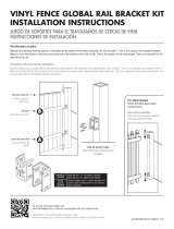
Vinyl rail posts require an internal
support system for weight-bearing
purposes and therefore a post install
kit or wood post is required inside a
post jacket. Post install kit and wood
post need to be purchased separately.
Top View of Post Jacket
Top View of Post Jacket
Rail
Rail
Purchased
Post Install Kit
Line Brackets*
Top Rail
Bottom Rail
Support Brace
Spindles
Spindles
Spindles
Spindles
Spindles
Spindles
Spindles
Spindles
Spindles
Spindles
Spindles
Spindles
Spindles
Spindles
Spindles
Spindles
Spindles
Spindles
Spindles
Spindles
Top Rail
Bottom Rail
Balusters
Balusters
Balusters
Balusters
Balusters
Balusters
Balusters
Balusters
Balusters
Stair Brackets*
Railing Kit
Stair Railing Kit
Angle Brackets*
Screws
To obtain and review a copy of the warranty please go to: Veranda.BarretteOutdoorLiving.com/warranty.
You can also contact 1-877-279-4496 or write to Veranda, 7830 Freeway Circle, Middleburg Heights,
Ohio 44130 to obtain a copy of the warranty.

3
Assembling rail section:
Lock tabs on balusters/spindles must face outer edge
of routed holes in rails. Assemble your rail section by
snapping balusters/spindles in rails (Fig.1).
a. One support brace is included with 6' railing kits.
Measure equal distance from both ends of railing and
install support brace in center of bottom rail.
For 67
1
⁄
1
⁄
1
2
⁄2⁄
" rail: install center of support brace
33
3
⁄
3
⁄
3
4
⁄4⁄
" from ends of rail (Fig. 2).
b. Two support braces are included with 8' railing kits.
Measure length of rail, divide by 3 and measure that
distance from your rail to the center of your rst
support brace and install support brace. Repeat that
step from the opposite side of your rail.
For other rail lengths: install support braces evenly.
NOTE:
Closely follow post manufacturer's installation instructions
or use a Post Jacket on an existing wood 4x4.
1
2
VINYL RAILING
Fig. 2
33
3
⁄
3
⁄
3
4
⁄4⁄
"
3" Support
Brace
33
3
⁄
3
⁄
3
4
⁄4⁄
"
Fig. 1
Locking Tab
Cut two 3" temporary wood spacer blocks (not included)
to insert under ends of railing sections to temporarily
assist in aligning railing section (Fig. 3).
Screw in top rail metal brackets to underside of each
end of rail, with #10 x 1
1
⁄
1
⁄
1
4
⁄4⁄
" square drive screw (sold
separately) in middle slot of bracket (Fig. 4). Do not
tighten at this time (allows for adjustment).
Slide the bottom rail bracket over bottom rail on each
end (Fig. 5).
3
4
5
3" Support
Brace
3" Wood
Block
Fig. 3
Fig. 4
Fig. 5

4
Fig. 6
Slide rail section in-between posts and on top of
temporary spacer blocks (position spacer blocks next to
installed vinyl posts) (Fig. 6).
6
For Top Brackets:
a. Center rail on post. Then, using a
5
⁄
5
⁄
5
32
⁄32⁄
" drill bit, pre-
drill the rst hole on an angle though the top rail
bracket, vinyl post jacket, and into wood post
(or plastic spacer of post install kit) (Fig. 7).
b. Install the #10 x 2
1
⁄
1
⁄
1
2
⁄2⁄
"square drive screws (Fig. 8).
Looking down from above, check to ensure screws
penetrate the
wood post (or plastic spacer of post
install kit) (Fig. 9).
7
Fig. 9
Fig. 7
Fig. 8
Rail
Screws
Post
Plastic
Spacer
Post
Install Kit

5
Top Bracket Covers:
a. Ensure the railing is centered between both posts
and tighten the set screws put into the metal
brackets from Step 4.
b. Open the top rail bracket cover to allow it to wrap
around the top rail (Fig. 10). While open, make sure
the "tab" ts behind the rail and against the post
(Fig. 11).
c. While tightly squeezing the bracket cover closed,
pre-drill using a
5
⁄
5
⁄
5
32
⁄32⁄
" drill bit through the two holes
underneath. Then, drive two #10 x 1
1
⁄
1
⁄
1
4
⁄4⁄
" square drive
screws through the cover, metal bracket and into the
top rail (Fig. 12).
8
Fig. 11
Fig. 10
Fig. 12
Top rail bracket cover
Tab
For Bottom Brackets:
a. Center rail on post. Then, using a
5
⁄
5
⁄
5
32
⁄32⁄
" drill bit, pre-
drill the rst hole on an angle though the bottom rail
bracket, vinyl post jacket, and into wood post
(or plastic spacer of post install kit).
b. Install the #10 x 1
1
⁄
1
⁄
1
4
⁄4⁄
" square drive screws (Fig. 13).
Bottom Bracket Covers:
Slide bottom bracket covers snugly onto bottom brackets
(Fig 14)
.
9
10
Predrill and install screws
Fig. 13
Fig. 14

6
VINYL STAIR RAILING
Place assembled stair rail section adjacent to the
mounted stair posts (Fig. 1). Measure the distance from
the rst and last baluster to the top and bottom posts
making sure distance is equal on both sides of stair rail
section (Fig. 2). Clamp into place (Fig. 3).
NOTE:
Some installations may require longer stair posts.
Trace the post onto each rail (both ends of top and
bottom rails). Make four marks in total (Fig. 4).
1
2
Equal Spacing
Fig. 1
Fig. 2
Fig. 3
Fig. 4

7
Remove clamped stair kit from posts. Cut along all four
angled marks on rails (Fig. 5).
Slide the angle brackets onto the rails (Fig. 6), and place
rail section between your posts (Fig. 7).
3
4
Fig. 5
Fig. 6
Fig. 7

8
Mark all bracket holes (Fig. 8). Predrill all bracket holes
with
1
⁄
1
⁄
1
8
⁄8⁄
" drill bit (Fig. 9).
Drive screws through brackets into post (Fig. 10). For top
rail, use #10 x 2" self-tapping square drive screws (two
per bracket); for bottom rail, use #10 x 1
1
⁄
1
⁄
1
4
⁄4⁄
" self-tapping
square drive screws (four per bracket).
Predrill one side (outside of the stair rail installation)
of the top rail bracket with
5
⁄
5
⁄
5
32
⁄32⁄
" drill bit. Hole should
be oriented as shown, approximately
3
⁄
3
⁄
3
8
⁄8⁄
" in from the
end of the bracket (Fig. 11). Drive #10 x 1" pan head
square drive screw through bracket and rail. Do NOT
overtighten.
5
6
7
Fig. 8
Fig. 9
Fig. 10
Fig. 11

9
After posts have been installed, determine angle and
height of railing (Fig. 1).
Pre-drill
1
⁄
1
⁄
1
8
⁄8⁄
" diameter holes in base of top bracket only.
Then, fasten bracket to base at the determined angle
with two #10 x 1" square drive screws (Fig. 2).
Cut railing to desired length. Place bracket on each end
of top and bottom rails (Fig. 3). Fasten bottom bracket to
base with one #10 x 1" square drive screw.
a. Position the rail section between the posts (Fig. 4).
b. Mark four screw hole locations on each bracket. Set
rail section aside, then pre-drill
1
⁄
1
⁄
1
8
⁄8⁄
" diameter holes in
post at each mark (Fig. 5).
1
2
3
4
Fig. 1
Fig. 4
Fig. 5
ANGLE BRACKETS
Determine
Angle
Top View
Fig. 2
#10 x 1" Screws
Fig. 3
Top Rail
Top Rail
Top Rail
Bottom
Rail
Mark Holes
Mark Holes
Top View

10
Attach each 2" top rail bracket with four #10 x 2"
square drive screws (Fig. 6). Attach each bottom rail
bracket with four #10 x 1
1
⁄
1
⁄
1
2
⁄2⁄
" screws.
Pre-drill one
1
⁄
1
⁄
1
8
⁄8⁄
" diameter hole through top rail and
aluminum insert for each side of top rail brackets only.
Fasten with #10 x 1" at head square drive screws (Fig. 7).
Add two screw covers for both top and bottom brackets
and add two screw caps for each top rail bracket (Fig. 8).
Repeat installation process for each additional
rail assembly.
5
6
7
8
Fig. 6
Fig. 7
Fig. 8
Cover
Cover
Cap

11

12

INSTRUCCIONES DE INSTALACIÓN
Barandal de vinilo y
barandal de escaleras
Para los estilos Traditional y Williamsburg
34107832BOM V2
Lea todas las instrucciones antes de la instalación del producto.
Consulte las instrucciones de seguridad del fabricante al utilizar herramientas.
Para registrar su producto, visite:
Para registrar su producto, visite:
veranda.barretteoutdoorliving.com
• English ..............................................................................1
• Español ...........................................................................12

14
Cinta métrica
Nivel
Taladro
Brocas de
5
⁄
5
⁄
5
32
⁄32⁄
" y
1
⁄
1
⁄
1
8
⁄8⁄
"
Dado cuadrado #2
Bloques de madera de 7.6 cm
Segueta
Abrazaderas
Gafas de protección
HERRAMIENTAS QUE SE
REQUIEREN:
ANTES DE COMENZAR:
ADVERTENCIA:
• La instalación incorrecta de este producto puede resultar en lesiones corporales. Utilice siempre gafas
de seguridad al cortar, taladrar y ensamblar el producto.
• La instalación incorrecta puede causar daños al producto o a personas.
• No aprobado por el código de piscinas
AVISO:
• NO intente ensamblar el kit si faltan piezas o las piezas están dañadas.
• NO devuelva el producto a la tienda. Para obtener ayuda o piezas de repuesto, llame al: 1-800-336-2383
Barandal y barandal de
escalera Componentes:
*Venden por separado.
Descripción
Soportes de línea y cubiertas*
Soportes para escaleras*
Soportes angulares y cubiertas*
Travesaños superiores
Travesaños inferiores
Barrotes/Pilares
Soportes de refuerzo
Tornillos cuadrados
Los postes del barandal de vinilo requieren
un sistema de soporte interno para poder
soportar el peso y, por lo tanto, es necesario
usar un kit de instalación de postes o un
poste de madera dentro de la funda de
poste. El kit de instalación de postes y el
poste de madera se compran por separado.
Vista superior de la funda de poste
Vista superior de la funda de poste
Travesaño
Travesaño
Travesaño
Travesaño
Travesaño
Travesaño
Travesaño
Travesaño
Travesaño
Comprado
Kit de
instalación de
poste
Soportes
de línea*
Travesaño superior
Travesaño inferior
Soporte de refuerzo
Husillos
Husillos
Husillos
Husillos
Husillos
Husillos
Husillos
Travesaño superior
Travesaño inferior
Barrotes
Barrotes
Barrotes
Barrotes
Barrotes
Barrotes
Barrotes
Barrotes
Barrotes
Barrotes
Barrotes
Barrotes
Soportes para
escaleras*
Kit de barandales
Kit de barandal de escaleras
Soportes
angulares*
Tornillos
Para obtener y revisar una copia de la garantía, vaya a: Veranda.BarretteOutdoorLiving.com/warranty.
También puede llamar al 1-877-279-4496 o escribir a Veranda, 7830 Freeway Circle, Middleburg Heights,
OH 44130 para obtener una copia de la garantía.

15
Ensamblado del tramo de barandal:
Las lengüetas de cierre automático en los barrotes o
pilares deben estar orientadas hacia el borde exterior
de los ori cios ranurados en los travesaños. Ensamble
el tramo de barandal encajando los barrotes o pilares
en los travesaños (Fig.1).
a. Se incluye un soporte de refuerzo en los kits de
barandal de 1.83 m (6 pies). Mida una distancia igual
a partir los dos extremos del barandal e instale el
soporte en la parte intermedia del travesaño inferior
En un travesaño de 1.71 m (67.5"), instale la parte
intermedia del soporte de refuerzo a 83.8 cm (33.75")
de los extremos del travesaño (Fig. 2)
b. Se incluyen dos soportes de refuerzo en los kits de
barandal de 2.44 m (8 pies). Mide la longitud del
travesaño, divídalo entre tres y mida la distancia del
travesaño a la parte intermedia del primer soporte
de refuerzo e instálelo. Repita este paso en el lado
opuesto del travesaño.
En caso de que el travesaño tenga otras
dimensiones: instale los soportes de refuerzo de
manera uniforme.
NOTA:
Siga atentamente las instrucciones de instalación del
fabricante o utilice una funda de poste sobre un poste de
madera existente de 4x4.
1
2
BARANDAL DE VINILO
Fig. 2
33
3
⁄
3
⁄
3
4
⁄4⁄
"
Soporte
de 7.6 cm
(3")
33
3
⁄
3
⁄
3
4
⁄4⁄
"
Fig. 1
Lengüeta
Corte dos bloques espaciadores temporales de madera
de 7.62 cm (3") (no incluidos) para insertarlos debajo de
los extremos de los tramos de barandal. Esto le ayudará
temporalmente a alinear los tramos de barandal (Fig. 3)
Atornille los soportes metálicos del travesaño superior
por debajo de cada extremo del travesaño, con un
tornillo cuadrado #10 de 1
1
⁄
1
⁄
1
4
⁄4⁄
" (se vende por separado)
en la ranura intermedia del soporte (Fig. 4). No apriete
en este momento (permite realizar ajustes).
Deslice el soporte del travesaño inferior por encima del
travesaño inferior en cada extremo (Fig. 5).
3
4
5
Soporte de
7.6 cm (3")
Bloque de madera
de 7.6 cm (3")
Fig. 3
Fig. 4
Fig. 5

16
Fig. 6
Deslice el tramo de travesaño entre los postes y encima
de los bloques espaciadores temporales de madera
(coloque los bloques junto a los postes de vinilo
instalados) (Fig. 6).
6
Para los soportes superiores:
a. Centre el travesaño sobre el poste. a continuación,
con la ayuda de una broca de
5
⁄
5
⁄
5
32
⁄32⁄
", taladre el primer
agujero en ángulo a través del soporte de travesaño
superior, la funda de poste de vinilo y hasta el poste
de madera (o el espaciador de plástico del kit de
instalación del poste) (Fig. 7).
b. Instale los tornillos cuadrados #10 de 2
1
⁄
1
⁄
1
2
⁄2⁄
" (Fig. 8).
Mirando de arriba abajo, compruebe que los tornillos
penetren en el poste de madera (o espaciado de
plástico del kit de instalación del poste) (Fig. 9).
7
Fig. 9
Fig. 7
Fig. 8
Travesaño
Tornillos
Poste
Espaciador
de plástico
Kit de
instalación
de poste

17
Cubiertas de soporte superior:
a. Asegúrese de que el barandal esté centrado entre
los dos postes y apriete los tornillos de ajuste en los
soportes metálicos del Paso 4.
b. Abra la cubierta del soporte de travesaño superior
para permitir que envuelva el travesaño superior
(Fig. 10). Mientras está abierto, compruebe que la
"lengüeta" quede detrás del travesaño y contra el
poste (Fig. 11).
c. Mientras aprieta fuertemente la cubierta del soporte
para que quede cerrada, taladra con una broca
de
5
⁄
5
⁄
5
32
⁄32⁄
" a través de los dos ori cios por debajo. A
continuación, pase dos tornillos cuadrados #10 de
1
1
⁄
1
⁄
1
4
⁄4⁄
" a través de la cubierta, el soporte metálico y
hasta el travesaño superior (Fig. 12).
8
Fig. 11
Fig. 10
Fig. 12
Cubierta de soporte de
travesaño superior
Lengüeta
Para los soportes inferiores:
a. Centre el travesaño sobre el poste. a continuación,
con la ayuda de una broca de
5
⁄
5
⁄
5
32
⁄32⁄
", taladre el primer
agujero en ángulo a través del soporte de travesaño
inferior, la funda de poste de vinilo y hasta el poste
de madera (o el espaciador de plástico del kit de
instalación del poste).
b. Instale los tornillos cuadrados #10 de 1
1
⁄
1
⁄
1
4
⁄4⁄
" (Fig. 13).
Cubiertas de soporte inferior:
Deslice las cubiertas de soporte inferior hasta que cubra
perfectamente los soportes inferiores (Fig. 14).
9
10
Taladre e instale los tornillos
Fig. 13
Fig. 14

18
BARANDAL DE ESCALERA DE VINILO
Coloque el tramo de barandal de escalera ensamblado
junto a los postes de escalera ya instalados (Fig. 1). Mida
la distancia del primer y último barrote hasta los postes
superior e inferior, cerciorándose de que la distancia
sea igual en ambos lados del tramo de barandal de las
escaleras (Fig. 2). Fíjese en su lugar con una pinza (Fig. 3).
NOTA:
Algunas instalaciones pueden requerir postes de
escalera más largos.
Trace el poste en cada uno de los travesaños (ambos
extremos de los travesaños superior e inferior). Haga
cuatro marcas en total (Fig. 4).
1
2
Espacios
iguales
Fig. 1
Fig. 2
Fig. 3
Fig. 4

19
Retire las pinzas del kit de escalera de los postes.
Corte a lo largo de las cuatro marcas en ángulo en los
travesaños (Fig. 5).
Deslice los soportes angulares sobre los travesaños (Fig. 6),
y coloque el tramo de travesaño entre los postes (Fig. 7).
3
4
Fig. 5
Fig. 6
Fig. 7

20
Marque todos los agujeros del soporte (Fig. 8). Taladre
los agujeros del soportes con una broca de
1
⁄
1
⁄
1
8
⁄8⁄
" (Fig. 9).
Instale los tornillos a través de los soportes y hasta
el poste (Fig. 10). En el travesaño superior, utilice los
tornillos cuadrados autorroscante #10 de 2" (dos por
soporte); para el travesaño inferior, utilice tornillos
cuadrados autorroscante #10 de 1
1
⁄
1
⁄
1
4
⁄ 4⁄
" (cuatro por
soporte)
Taladre uno de los lados (fuera de la instalación de
travesaño de escalera) del soporte de travesaño superior
con una broca de
5
⁄
5
⁄
5
32
⁄ 32⁄
". El ori cio debe estar orientado
como se muestra, a aproximadamente
3
⁄
3
⁄
3
8
⁄8⁄
" del extremo
del soporte (Fig. 11). Instale un tornillo cuadrado de
cabeza achatada #10 de 1" a través del soporte y del
travesaño. No apretar en exceso.
5
6
7
Fig. 8
Fig. 9
Fig. 10
Fig. 11

21
Después de instalar los postes, determine el ángulo y la
altura del baranda (Fig. 1).
Taladre ori cios de
1
⁄
1
⁄
1
8
⁄8⁄
" de diámetro en la base del
soporte superior únicamente. A continuación, je el
soporte a la base en el ángulo determinado con dos
tornillos cuadrados #10 de 1" (Fig. 2).
Corte el barandal a la longitud deseada. Coloque un
soporte en cada extremo de los travesaños superior e
inferior (Fig. 3). Fije el soporte inferior a la base con un
tornillo cuadrado #10 de 1".
a. Coloque el tramo de barandal entre los postes (Fig. 4).
b. Marque cuatro ubicaciones para los ori cios de
los tornillos en cada soporte. Coloque el tramo
de barandal por un lago y, a continuación, taladre
agujeros de
1
⁄
1
⁄
1
8
⁄8⁄
" de diámetro en cada marca (Fig. 6).
1
2
3
4
Fig. 1
Fig. 4
Fig. 5
SOPORTES ANGULARES
Determine
el ángulo
Vista superior
Fig. 2
Tornillos #10 de 1”
Fig. 3
Travesaño Travesaño
superior
superior
superior
superior
superior
superior
superior
superior
superior
superior
superior
superior
superior
superior
superior
superior
superior
superior
superior
superior
superior
superior
superior
superior
superior
superior
superior
superior
superior
superior
Travesaño
inferior
Marque los agujeros
Marque los agujeros
Marque los agujeros
Marque los agujeros
Marque los agujeros
Marque los agujeros
Vista superior

22
Fije cada soporte de travesaño superior de 2" con cuatro
tornillos cuadrados #10 de 2" (Fig. 6). Fije cada soporte
de travesaño inferior con cuatro tornillos #10 de 1
1
⁄
1
⁄
1
2
⁄2⁄
".
Taladre un agujero de
1
⁄
1
⁄
1
8
⁄8⁄
" de diámetro a través del
travesaño y de la inserción de aluminio para cada uno
de los lados de los soportes de travesaño superior
únicamente. Sujetar con tornillos cuadrados de cabeza
plana #10 de 1" (Fig. 7).
Añada dos cubiertas de tornillo en los soportes inferior
y superior y dos tapones de tornillo en cada soporte de
travesaño superior (Fig. 8).
Repita el proceso de instalación para cada conjunto de
barandal adicional.
5
6
7
8
Fig. 6
Fig. 7
Fig. 8
Cubierta
Cubierta
Tapón

23

BARRETTE OUTDOOR LIVING
7830 FREEWAY CIRCLE
MIDDLEBURG HEIGHTS, OHIO 44130
TEL: (800) 336-2383
WWW.VERANDA.BARRETTEOUTDOORLIVING.COM
/