
FIG. 4
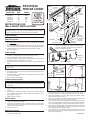
PRESTIQUE
MEDICINE CABINET
WARNING: Installation work and electrical wiring must be done by a
qualified person(s) in accordance with all applicable codes and stan-
dards, including fire-rated construction codes and standards.
Prepare cabinet.
1. Carefully remove all packing material.
Determine location.
1. The commonly accepted height of bath cabinets is 64" from the finished
floor to the center of the mirror area. However, height may be adjusted
to individual preference.
2. It is recommended that the cabinet be located such that the mounting
screws may be screwed into wall studs to provide maximum strength.
3. Provide 120 VAC power cable through the wall material, directly
behind the light box.
Mount cabinet.
1. Measure and mark four (4) clearance holes in cabinet back at wall stud
locations. Use angle brackets to locate upper holes. (Fig. 1)
2. Drill ¼" dia. clearance holes through cabinet back.
3. Hold angle brackets in place over top set of holes. Mount brackets to
underside of light housing with #6 x ½" screws.
4. Hold cabinet in place and make sure it is level. Screw cabinet to wall
studs.
NOTE: Irregularities in wall surface may cause distortion of cabinet
body when mounted. Place shims between cabinet and wall at appro-
priate corners.
OPTION (If wall studs are not available):
4. Hold cabinet in place and make sure it is level. Mark wall through all four
(4) clearance holes.
5. Set cabinet aside and drill holes in wall material for molly bolts or wall
anchors (not provided).
6. Mount cabinet to wall material.
Connect electrical wiring.
WARNING: Before wiring this product, switch power off at service en-
trance and lock service panel to prevent power from being switched on
accidentally.
1. Remove reflector from wrapper.
2. Remove protective plastic film from reflector and snap light cups onto
sockets.
3. Make electrical connections between house wires and fixture wires on
rear of reflector: black to black, white to white, and greenwire to a per-
manent ground. (FIG. 2)
4. Attach reflector to cabinet.
Mount shelves.
1. Choose the location for the shelves from the five (5) sets of holes lo-
cated on the inside of the cabinet.
2. Insert two (2) shelf tabs into holes, at desired location on one side of the
cabinet. Repeat on the other side, being sure to use holes at the same
height, so the shelf will be level.
3. Set shelves on pins.
Attach mirror doors.
1. Remove wrapping from mirror door. Remove hinge brackets and pres-
sure plates from parts bag.
FIG. 1
FIG. 2
WIRING
ACCESS
HOLE
LIGHT
SOCKET
CUP
MIRROR
DOOR
A99042675C
HINGE
BRACKET
(Pressure plate
beneath
backside)
NYLON
WASHER
BACKSIDE OF
MIRROR DOOR
PRESSURE
PLATE
FIG. 3
HINGE
BRACKET
FIG. 6
FIG. 5
2. Peel paper backing from two (2) pressure plates and affix plates to
backside of mirror door at upper-left and lower-left corners. (FIG. 3)
3. Slide hinge bracket(s) over top of door(s) and lightly tighten screws
against pressure plate(s). (FIG. 3)
4. Place a nylon washer on the pin of the remaining hinge bracket and
insert hinge bracket(s) into hole(s) in bottom of frame.
5. Lift mirror door(s) and insert top hinge bracket(s) into hole(s) in top of
frame. (FIG. 4) Slide bottom of mirror door(s) into lower hinge bracket(s)
(FIG. 5) and lightly tighten screws against pressure plate(s). (FIG 6)
6. Remove the 1" diameter strike plate(s) from the parts bag. Peel off the
paper backing and affix plate(s) to rear of mirror door(s) at the lower
corner(s) opposite the magnetic catch(es).
7. Clear urethane discs are furnished to prevent finger marks on mirror
face. To mount: Remove paper backing and affix to mirror face ½” from
bottom and outside edge.
REFLECTOR
URETHANE DISC
STRIKE
PLATE
MAGNET
SHELF
SHELF
TABS
SCREW
#6 x 3/8”
CLEARANCE
HOLES
SCREW
#6 x ½”
ANGLE
BRACKET
All electrical connections must be made in accordance
with local code ordinances. If you are unfamiliar with
methods of installing electrical wiring, secure the ser-
vices of a qualified electrician.
WHITE TO WHITE
BLACK TO BLACK
GREEN TO
GROUND
WIRE
INSTRUCTIONS FOR
WALL-MOUNT INSTALLATIONS
MODEL NO. SIZE FINISH
942224-P1 24” White
942230-K1 30” White
942236-K1 36” White
947224-Q1 24” Oak
947230-Q1 30” Oak
947236-Q1 36” Oak
SCREW
#8 x 1½”
For help, call
us toll free!
1-800-637-1453

WARNING: Installation work and electrical wiring must be done by a
qualified person(s) in accordance with all applicable codes and stan-
dards, including fire-rated construction codes and standards.
Prepare cabinet.
1. Carefully remove all packing material.
Determine location.
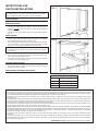
1. Mark the wall to show wall opening size. (See dimension chart) Note:
Commonly accepted height of a medicine cabinet is 64" from the fin-
ished floor to center of mirror area. However, height may be adjusted to
individual preference.
2. Provide 120 VAC power cable through wall, directly behind light box.
(Fig. 7)
Mount cabinet.
1. Cut out wall opening, being careful not to damage the surrounding wall
surface. (Fig. 7) The rough wall opening must be free of all obstruc-
tions. Additional framing must be provided. (Fig. 8)
2. Drill (2) 3/16” diameter clearance holes through the left side of the cabi-
net. Locate holes 1½” in from
inside
top and bottom edges of cabinet
and 1½” from
inside
back of cabinet. Repeat on other side.
WARNING: Before wiring this product, switch power off at service en-
trance and lock service panel to prevent power from being switched
on accidentally.
3. Remove face plate from cabinet.
4. Pull 6" of power cable through access hole in light fixture box and se-
cure cable to box with proper connector.
5. Insert cabinet into wall opening and secure to wall studs through four
clearance holes with mounting screws.
Connect electrical wiring.
1. Strip ½” of insulation from wires. Make electrical connections: black to
black, white to white, and green or bare wires to a permanent ground.
2. Re-attach face plate to cabinet.
Mount shelves and attach mirror doors.
1. Follow instructions on other side of this sheet.
INSTRUCTIONS FOR
BUILT-IN INSTALLATIONS
BROAN ONE YEAR LIMITED WARRANTY
Broan warrants to the original consumer purchaser of its products that such products will be free from defects in materials or workmanship for a period
of one year from the date of original purchase. THERE ARE NO OTHER WARRANTIES, EXPRESS OR IMPLIED, INCLUDING, BUT NOT LIMITED
TO, IMPLIED WARRANTIES OF MERCHANTABILITY OR FITNESS FOR A PARTICULAR PURPOSE.
During this one-year period, Broan will, at its option, repair or replace, without charge, any product or part which is found to be defective under normal
use and service.
THIS WARRANTY DOES NOT EXTEND TO FLUORESCENT LAMP STARTERS AND TUBES. This warranty does not cover (a) normal maintenance
and service or (b) any products or parts which have been subject to misuse, negligence, accident, improper maintenance or repair (other than by Broan),
faulty installation or installation contrary to recommended installation instructions.
The duration of any implied warranty is limited to the one-year period as specified for the express warranty. Some states do not allow limitation on how
long an implied warranty lasts, so the above limitation may not apply to you.
BROAN’S OBLIGATION TO REPAIR OR REPLACE, AT BROAN’S OPTION, SHALL BE THE PURCHASER’S SOLE AND EXCLUSIVE REMEDY
UNDER THIS WARRANTY. BROAN SHALL NOT BE LIABLE FOR INCIDENTAL, CONSEQUENTIAL OR SPECIAL DAMAGES ARISING OUT OF OR
IN CONNECTION WITH PRODUCT USE OR PERFORMANCE. Some states do not allow the exclusion or limitation of incidental or consequential
damages, so the above limitation or exclusion may not apply to you.
This warranty gives you specific legal rights, and you may also have other rights, which vary from state to state. This warranty supersedes all prior
warranties.
To qualify for warranty service, you must (a) notify Broan at the address stated below or telephone: 1-800-637-1453, (b) give the model number and
part identification and (c) describe the nature of any defect in the product or part. At the time of requesting warranty service, you must present evidence
of the original purchase date.
BROAN MFG. CO., INC., 926 West State Street, Hartford, WI 53027
FIG. 7
FIG. 8
DIMENSIONS W x H x D
Size Wall Opening Size
24” 22
5
/
8
x 27
1
/
4
x 3½
30" 28
5
/
8
x 27
1
/
4
x 3½
36" 34
5
/
8
x 27
1
/
4
x 3½

FIG. 4
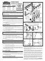
PRESTIQUE
CABINA DE LA MEDICINA
ADVERTENCIA: Una persona o personas calificadas deben realizar el
trabajo de instalación y el cableado eléctrico, de acuerdo con todos los
códigos y normas aplicables, inclusive los códigos y normas de construcción
referentes a incendios.
Preparación del gabinete.
1. Retire cuidadosamente todo el material de embalaje.
Determinación de la ubicación del gabinete.
1. La altura normalmente aceptada de los gabinetes para baño es de
162.6 cm (64") desde el piso terminado hasta el centro del área del espejo.
Sin embargo, puede ajustar el gabinete de acuerdo con su preferencia per-
sonal.
2. Se recomienda ubicar el gabinete de manera que los tornillos de
montaje se puedan atornillar en los montantes de la pared para proporcionar
la mayor resistencia.
3. Tienda un cable de alimentación de 120 VCA a través de la pared,
directamente detrás de la caja de iluminación.
Montaje del gabinete.
1. Mida y marque cuatro (4) orificios de separación en la parte posterior
del gabinete, en las áreas donde éste se va a fijar en los montantes. Utilice
soportes angulares para ubicar los orificios superiores (Fig. 1).
2. Haga con un taladro con broca de 1/4" los orificios de separación a
través de la parte posterior del gabinete.
3. Sujete los soportes angulares en su lugar sobre el grupo superior de
tornillos. Con los tornillos #6 x 1/2" monte los soportes en la parte interna del
alojamiento de las lámparas.
4. Sostenga el gabinete en su lugar y asegúrese de que está nivelado.
Atornille el gabinete en los montantes de la pared.
NOTA: Las irregularidades de la superficie de la pared pueden ocasionar
que el gabinete montado quede desnivelado. Coloque calzos en las
esquinas apropiadas entre el gabinete y la pared.
OPCIÓN (si no hay disponibles montantes de la pared)
4. Sostenga el gabinete en su lugar y asegúrese de que esté nivelado.
Marque la pared a través de los cuatro (4) orificios de separación.
5. Ponga el gabinete a un lado y con un taladro haga orificios en la
pared para pernos tipo Molly o dispositivos de fijación a la pared (no se
proporcionan).
6. Monte el gabinete en la pared.
Conexión eléctrica.
ADVERTENCIA: Antes de hacer las conexiones eléctricas para este
producto interrumpa la energía eléctrica en la entrada del servicio y bloquee
el panel de servicio para evitar que alguien restablezca accidentalmente la
energía.
1. Saque el reflector de su envoltura.
2. Quite la película protectora de plástico del reflector y conecte las
copas de las lámparas en los receptáculos.
3. Haga las conexiones eléctricas entre el cableado doméstico y los
alambres del portalámparas que se encuentran en la parte posterior del re-
flector: el negro con el negro, el blanco con el blanco, y el verde con una
conexión permantnente a tierra. (Fig. 2)
4. Conecte el reflector en el gabinete.
Montaje de las repisas.
1. Seleccione la ubicación de las repisas entre los cinco (5) conjuntos
de orificios que se localizan en el interior del gabinete.
2. Introduzca dos (2) soportes para repisa en los orificios de la ubicación
deseada en uno de los lados del gabinete. Repita el procedimiento en el otro
lado, asegurándose de usar los orificios que estén a la misma altura para
que la repisa quede nivelada.
3. Coloque las repisas sobre sus soportes.
Colocación de las puertas de espejo.
1. Saque la puerta de espejo de su envoltura. Saque las ménsulas de
articulación y las placas de presión de la bolsa de piezas.
FIG. 1
FIG. 2
PUERTA
DE
ESPEJO
MÉNSULA DE
ARTICULACIÓN
(Placa de
presión debajo
del lado de
atrás)
ARANDELA DE NILÓN
PLACA DE
PRESIÓN
FIG. 3
FIG. 6
FIG. 5
2. Quite el soporte de papel de las dos (2) placas de presión y péguelas en
la parte posterior de la puerta de espejo en las esquinas superior
izquierda e inferior izquierda (Fig. 3).
3. Deslice la ménsula o ménsulas de articulación sobre la parte superior
de la puerta o puertas y apriete ligeramente los tornillos sobre la placa
o placas de presión (Fig. 3)
4. Coloque una arandela de nilón en el perno de la ménsula de articulación
remanente e introduzca la ménsula o ménsulas de articulación en el
orificio u orificios que se encuentran en la parte inferior del marco.
5. Levante la puerta o puertas de espejo e introduzca la ménsula o ménsulas
de articulación superiores en el orificio u orificios de la parte superior
del marco (Fig. 4). Deslice la parte inferior de la puerta o puertas de
espejo en la ménsula o ménsulas de articulación inferior (Fig. 5) y apriete
ligeramente los tornillos contra la placa o placas de presión (Fig. 6).
6. Saque la placa o placas de protección contra impactos de 25.4 mm (1")
de diámetro de la bolsa de piezas. Quítele el soporte de papel y pegue
la placa o placas en la parte posterior de la puerta o puertas de espejo,
en la esquina inferior, en posición opuesta al imán.
7. Se suministra un disco de uretano transparente para evitar dejar marcas
de dedos en la cara del espejo. Para montarlo: quítele el soporte de
papel y péguelo en la cara del espejo a una distancia de 12.7 mm (1/2")
REFLECTOR
DISCO DE URETANO
PLACA DE
PROTECCIÓN
CONTRA
IMPACTOS
IMÁN
SOPORTES
PARA REPISA
TORNILLO #6
x 3/8"
ORIFICIOS DE
SEPARACIÓN
TORNILLO
#6 X 1/2"
NEGRO A NEGRO
MODELO No. TAMAÑO ACABADO
942224-P1 609 mm (24") Blanco
942230-K1 762 mm (30") Blanco
942236-K1 914 mm (36") Blanco
947224-Q1 609 mm (24") Roble
947230-Q1 762 mm (30") Roble
947236-Q1 914 mm (36") Roble
INSTRUCCIONES PARA LA INSTALACIÓN DEL GABINETE
SOBRE LA SUPERFICIE DE LA PARED
SOPORTE
ANGULAR
ORIFICIO DE ACCESO
PARA LA CONEXIÓN
Todas las conexiones eléctricas se deben hacer de acuerdo
con las ordenanzas del código local. Si no está
familiarizado con los procedimientos de cableado eléctrico,
procure los servicios de un electricista calificado.
BLANCO A BLANCO
VERDE AL
CABLE DE
CONEXIÓN A
TIERRA
MÉNSULA
DE
ARTICULACIÓN
PARTE POSTERIOR
DE LA PUERTA DE
ESPEJO
COPA
RECEPTÁCULO
DEL FOCO
REPISA
TORNILLO
#8 x 1-1/2"
Para la ayuda,
llámenos peaje libres.
1-800-637-1453
A99042675C

ADVERTENCIA: Una persona o personas calificadas deben realizar
el trabajo de instalación y el cableado eléctrico, de acuerdo con todos
los códigos y normas aplicables, inclusive los códigos y normas sobre
construcción referentes a incendios.
Preparación del gabinete.
1. Retire cuidadosamente todo el material de embalaje.
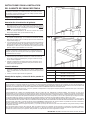
Determinación de la ubicación del gabinete.
1. Marque en la pared el tamaño de la abertura (vea la tabla de
dimensiones). Nota: La altura normalmente aceptada de un gabinete
para medicinas es de 162.6 cm (64") desde el piso terminado hasta el
centro del área del espejo. Sin embargo, puede ajustar el gabinete de
acuerdo con su preferencia personal.
2. Tienda un cable de alimentación de 120 VCA a través de la pared,
directamente detrás de la caja de iluminación (Fig. 7).
Montaje del gabinete.
1. Haga la abertura en la pared, teniendo cuidado de no dañar la superficie
de la pared circundante (Fig. 7). La abertura sin acabar de la pared
debe estar sin obstrucciones. Se debe proporcionar una estructura de
soporte adicional (Fig. 8).
2. Con un taladro haga dos (2) orificios de separación de 3/16" de diámetro
a través del lado izquierdo del gabinete. Ubique los orificios a una
distancia de 38.1 mm (1-1/2") de los bordes internos superior e inferior
del gabinete y a 38.1 mm (1-1/2") del interior de la parte posterior del
gabinete. Repita el procedimiento en el otro lado.
ADVERTENCIA: Antes de hacer las conexiones eléctricas en este
producto, interrumpa la energía eléctrica en la entrada del servicio y
bloquee el panel de servicio para evitar que alguien restablezca
accidentalmente la energía.
3. Quite la placa frontal del gabinete.
4. Saque 152 mm (6") del cable de alimentación a través del orificio de
acceso de la caja de los portalámparas y asegure el cable en la caja
con el conector apropiado.
5. Introduzca el gabinete en la abertura de la pared y asegúrelo con los
tornillos de montaje en los montantes de la pared a través de los
cuatro orificios de separación.
Conexión eléctrica.
1. Desprenda 12.7 mm (1/2") del material aislante de los cables. Haga las
conexiones eléctricas: el cable negro con el negro, el blanco con el
blanco, y el cable verde o el cable desnudo a una conexión permanente
a tierra.
2. Vuelva a conectar la placa frontal en el gabinete.
Montaje de las repisas y colocación de las puertas de
espejo.
1. Siga las instrucciones que se encuentran al reverso de esta página.
FIG. 7
FIG. 8
DIMENSIONES Anch x Alt x Prof
Tamaño Tamaño de la abertura de la pared
609 mm (24") 576 mm x 692 mm x 88 mm
(22-11/16" x 27-1/4" x 3-1/2")
762 mm (30") 728 mm x 692 mm x 88 mm
(28-11/16" x 27-1/4" x 3-1/2")
914 mm (36") 881 mm x 692 mm x 88 mm
(34-11/16" x 27-1/4" x 3-1/2")
GARANTÍA DE BROAN LIMITADA POR UN AÑO
Broan garantiza al comprador original de sus productos, que dichos productos estarán libres de defectos en el material y la mano de obra durante un
período de un año a partir de la fecha original de compra. NO EXISTEN OTRAS GARANTÍAS EXPRESAS NI IMPLÍCITAS, INCLUSIVE PERO SIN
LIMITARSE A GARANTÍAS IMPLÍCITAS DE COMERCIALIZACIÓN O IDONEIDAD PARA UN USO PARTICULAR.
Durante este período de un año Broan, a su juicio, reparará o reemplazará sin cargo alguno cualquier producto o parte del mismo que se encuentren
defectuosos bajo uso y servicio normales.
ESTA GARANTÍA NO CUBRE LOS ARRANCADORES NI LOS TUBOS DE LAS LÁMPARAS FLUORESCENTES. Esta garantía no cubre (a) el
mantenimiento y servicio normales ni (b) ningún producto o partes del mismo que hayan estado sujetos a mal uso, negligencia, accidente, mantenimiento
o reparación inadecuada (realizada por alguien diferente a Broan), instalación defectuosa o instalación diferente a la recomendada en las instrucciones.
La duración de cualquier garantía implícita está limitada a un período de un año como se especifica en el caso de la garantía expresa. Algunos estados
no permiten limitaciones respecto a la duración de una garantía implícita, de manera que esta limitación puede no aplicar en su caso.
LA OBLIGACIÓN DE BROAN DE REPARAR O REEMPLAZAR EL PRODUCTO, A OPCIÓN DE BROAN, SERÁ EL RECURSO ÚNICO Y EXCLUSIVO
DEL COMPRADOR DE ACUERDO CON ESTA GARANTÍA. BROAN NO SERÁ RESPONSABLE DE NINGÚN DAÑO INCIDENTAL, RESULTANTE NI
ESPECIAL QUE SURJA DEL, O EN RELACIÓN AL USO O RENDIMIENTO DEL PRODUCTO. Algunos estados no permiten la exclusión ni la limitación
de daños incidentales o resultantes, de manera que esta limitación puede no aplicar en su caso.
Esta garantía le confiere derechos legales específicos, y es posible que tenga otros derechos que varían entre estados. Esta garantía sustituye a todas
las garantías anteriores.
Para que pueda recibir el servicio de la garantía, debe (a) notificar a Broan en el domicilio que se especifica a continuación o al teléfono 1-800-637-
1453, (b) dar el número de modelo y la identificación de la pieza y (c) describir la naturaleza de cualquier defecto del producto o parte del mismo. El en
momento de solicitar servicio por la garantía, debe presentar un comprobante de la fecha original de la compra.
BROAN MFG. CO., INC., 926 West State Street, Hartford, WI 53027
INSTRUCCIONES PARA LA INSTALACIÓN
DEL GABINETE DE FORMA EMPOTRADA
-
 1
1
-
 2
2
-
 3
3
-
 4
4


Broan TV Mount 942224-P1 Manual de usuario
- Tipo
- Manual de usuario
en otros idiomas
- English: Broan TV Mount 942224-P1 User manual
Artículos relacionados

Otros documentos
-
Jensen 755296X Guía de instalación
-
none 755395X Guía de instalación
-
-
Jensen 52WH344PX Instrucciones de operación
-
none 740589 Guía de instalación
-
-
-
-
HyLoft 00967 Guía de instalación
-