Wayne Dalton WD9100RW167 Guía de instalación
- Categoría
- Abridor de puerta de garage
- Tipo
- Guía de instalación
Este manual también es adecuado para

©Copyright 2021
REV1_04/14/2021Part Number
Table Of Contents
365456
PLEASE DO NOT RETURN THIS PRODUCT
TO THE STORE
If you need assistance, please call 1-866-
569-3799 (press Option 1) and follow the
prompts to contact a customer service
representative. They will be happy to handle
any questions that you may have.
Pre-Installation 2
Important Safety Instructions 2
Removing an Existing Door and Preparing the Opening 2
Package Contents 3
Door Section Identification 4
Tools Required 4
Breakdown Of Parts 5
Door Installation Instructions 6
Counterbalance Installation Instructions 10
Maintenance 16
Cleaning Your Garage Door 16
Painting Your Garage Door 16
Maintaining The Finish On Your Garage Door 16
Operation And Maintenance 16
Warranty 17
Wayne Dalton, a division of Overhead Door Corporation
Models 9100 / 9605
T o r q u e M a s T e r
®
P l u s
InsTallaTIon InsTrucTIons and owner’s
Manual
resIdenTIal
sTandard lIfT
To avoid possible injury, read and fully understand the enclosed
instructions carefully before installing and operating the garage door. Pay
close attention to all warnings and notes. After installation is complete,
fasten this manual near garage door for easy reference.
IMPORTANT NOTICES!
This Installation document is available at no charge from:
- Your local Wayne Dalton Sales Center, or
- Online at www.Wayne-Dalton.com, or
- By mailing to: Wayne Dalton, a division of Overhead Door Corporation,
P.O. Box 67, Mt. Hope, OH., 44660
Watch: https://www.youtube.com/
watch?v=IgE-hPXz3iU&feature=youtu.be
INSTALLATION VIDEO

Important Safety Instructions
DEFINITION OF KEY WORDS USED IN THIS MANUAL:
WARNING
INDICATES A POTENTIALLY HAZARDOUS SITUATION WHICH; IF NOT
AVOIDED, COULD RESULT IN SEVERE OR FATAL INJURY.
CAUTION
PROPERTY DAMAGE OR INJURY CAN RESULT FROM FAILURE TO FOLLOW
INSTRUCTIONS.
IMPORTANT: Required step for safe and proper door operation.
NOTE: Information assuring proper installation of the door.
READ THESE INSTRUCTIONS CAREFULLY BEFORE ATTEMPTING INSTALLATION. IF
IN QUESTION ABOUT ANY OF THE PROCEDURES, DO NOT PERFORM THE WORK.
INSTEAD, HAVE A TRAINED DOOR SYSTEMS TECHNICIAN DO THE INSTALLATION OR
REPAIRS.
1. READ AND FOLLOW ALL INSTALLATION INSTRUCTIONS.
2. Wear protective gloves and eye protection during installation, to avoid possible injury.
3. Avoid installing your new door on windy days. Door could fall during the installation
causing severe or fatal injury.
4. Doors 12’-0” wide and over should be installed by two persons, to avoid possible
injury.
5. Operate door only when it is properly adjusted and free from obstructions.
6. If a door becomes hard to operate, inoperative or is damaged, immediately have
necessary adjustments and/ or repairs made by a trained door system technician using
proper tools and instructions.
7. DO NOT stand or walk under a moving door, or permit anybody to stand or walk under
an electrically operated door.
8. DO NOT place fingers or hands into open section joints when closing a door. Use lift
handles/ gripping points when operating door manually.
9. DO NOT permit children to operate garage door or door controls. Severe or fatal injury
could result should the child become entrapped between the door and the floor.
10. Due to constant extreme spring tension, do not attempt any adjustment, repair or
alteration to any part of the door, especially to springs, spring brackets, bottom corner
brackets, fasteners, counterbalance lift cables or supports. To avoid possible severe or
fatal injury, have any such work performed by a trained door systems technician using
proper tools and instructions.
11. On electrically operated doors, pull down ropes must be removed and locks must be
removed or made inoperative in the open (unlocked) position.
12. Top section of door may need to be reinforced when attaching an electric opener.
Check door and/ or opener manufacturer’s instructions.
13. Visually inspect door and hardware monthly for worn and or broken parts. Check to
ensure door operates freely. Test electric opener’s safety features monthly, following
opener manufacturer’s instructions.
14. NEVER hang tools, bicycles, hoses, clothing or anything else from horizontal tracks.
Track systems are not intended or designed to support extra weight.
15. This door may not meet the building code wind load requirements in your area. For
your safety, you will need to check with your local building official for wind load code
requirements and building permit information.
16. For windloaded doors, the wind performance is achieved via the entire door system
and component substitution is not authorized without express permission by Wayne
Dalton.
NOTE: It is recommended that 5/16” lag screws are pilot drilled using a 3/16” drill bit, prior
to fastening.
CAUTION
IF ANY PART OF THE DOOR IS TO BE INSTALLED ONTO PRESERVATIVE-
TREATED WOOD, PTFE-COATED OR STAINLESS STEEL FASTENERS MUST BE
OBTAINED AND USED. REPLACEMENT FASTENERS MUST BE OF AT LEAST
EQUAL STRENGTH AND SIZE AS ORIGINAL FASTENERS. IF THE ORIGINAL
FASTENER WAS RED-HEAD, THE REPLACEMENT FASTENER MUST BE RED-
HEAD ALSO. CONTACT WAYNE DALTON FOR FASTENER STRENGTH VALUES IF
NEEDED.
WARNING
IMPACT GUNS ARE NOT RECOMMENDED. WHEN INSTALLING 5/16” LAG
SCREWS USING AN ELECTRIC DRILL/ DRIVER, THE DRILL/ DRIVERS
CLUTCH MUST BE SET TO DELIVER NO MORE THAN 200 IN-LBS OF
TORQUE. FASTENER FAILURE COULD OCCUR AT HIGHER SETTINGS.
IMPORTANT: Right and left hand is determined inside the building looking out.
Potential Hazard Effect Prevention
Moving door
WARNING
Could result in Death or Serious
Injury
Keep people clear of opening
while Door is moving.
Do NOT allow children to play
with the Door Opener.
Do NOT operate a Door that
jams or one that has a broken
spring.
High tension spring
WARNING
Could result in Death or Serious
Injury
Do NOT try to remove, install,
repair or adjust springs or
anything to which door spring
parts are fastened, such as,
wood blocks, steel brackets,
cables or other like items.
Installations, repairs and
adjustments must be done by
a trained door system techni-
cian using proper tools and
instructions.
Removing an Existing Door and
Preparing the Opening
IMPORTANT: Counterbalance spring tension must always be released before any attempt
is made to start removing an existing door.
WARNING
A POWERFUL SPRING RELEASING ITS ENERGY SUDDENLY CAN CAUSE
SEVERE OR FATAL INJURY. TO AVOID INJURY, HAVE A TRAINED DOOR
SYSTEMS TECHNICIAN, USING PROPER TOOLS AND INSTRUCTIONS,
RELEASE THE SPRING TENSION.
To avoid possible injury and to ensure proper installation, it's highly recommended that you
read and fully understand the complete instructions on removing an Existing Door & Prepar-
ing the Opening. These are available for download at www.Wayne-Dalton.com or at your
local Wayne Dalton Sales Center.
IMPORTANT: If you just removed your existing door or you are installing a new door,
complete all steps in preparing the opening.
To ensure secure mounting of track brackets, side and center brackets, or steel angles to
new or retro-fit construction, it is recommended to follow the procedures outlined in DASMA
technical data sheets #156, #161 and #164 at www.dasma.com.
The inside perimeter of your garage door opening should be framed with wood jamb
and header material. The jambs and header must be securely fastened to sound framing
members. It is recommended that 2” x 6” lumber be used. The jambs must be plumb and
the header level. The jambs should extend a minimum of 12” (305 mm) above the top of the
opening for TorqueMaster
®
Plus counterbalance systems. For low headroom applications, the
jambs should extend to the ceiling height. Minimum side clearance required, from the open-
ing to the wall, is 3-1/2” (89 mm).
IMPORTANT: Closely inspect jambs, header and mounting surface. Any wood found not to
be sound, must be replaced.
For TorqueMaster
®
Plus counterbalance systems, a suitable mounting surface (2” x 6”) must
2
PRE-INSTALLATION

be firmly attached to the wall, above the header at the center of the opening.
NOTE: Drill a 3/16” pilot hole in the mounting surface to avoid splitting the lumber. Do not
attach the mounting surface with nails.
WEATHERSTRIPS (IF APPLICABLE): Depending on the size of your door, you may have to
cut or trim the weatherstrips (if necessary) to properly fit into the header and jambs.
NOTE: If nailing product at 40°F or below, pre-drilling is required.
For the header, align the weatherstrip with the inside edge of the header and temporarily
secure it to the header with equally spaced nails. Starting at either side of the jamb, fit the
weatherstrip up tight against the temporarily attached weatherstrip in the header and flush
with the inside edge of the jamb. Temporarily secure the weatherstrip with equally spaced
nails. Repeat for other side. This will keep the bottom section from falling out of the opening
during installation. Equally space nails approximately 12” to 18” apart.
HEADROOM REQUIREMENT: Headroom is defined as the space needed above the top of
the door for tracks, springs, etc. to allow the door to open properly. If the door is to be motor
operated, 2-1/2” (64 mm) of additional headroom is required.
NOTE: 6” low headroom conversion kit is available for 12” radius only. Contact your local
Wayne Dalton dealer.
BACKROOM REQUIREMENT: Backroom is defined as the distance needed from the opening
back into the garage to allow the door to open fully.
BACKROOM REQUIREMENTS
DOOR HEIGHT TRACK MANUAL LIFT MOTOR OPERATED
6’5” to 7’0” 12”,15” Radius 98” (2489 mm) 125” (3175 mm)
7’1” to 8’0” 12”,15” Radius 110” (2794 mm) 137” (3480 mm)
HEADROOM REQUIREMENTS
TRACK TYPE SPACE NEEDED
15” Radius track 13-1/2” (343 mm)
12” Radius track 11” (279 mm)
6” LHR KIT 6” (152 mm)
Weatherstrips
Level header
Finished
Door width
Jambs
Backroom
Plumb
jambs
Finished
Door
Height
Nail
Headroom
Header board 2”x 6”
lumber preferred
Suitable mounting surface
2”x 6” lumber minimum
Weatherstrips
Jamb
Quick Install track
Min. Side
room
Clearance
is 3-1/2”
Min. Side
room
Clearance
is 3-1/2”
Package Contents
NOTE: Depending on the door model, some parts listed will not be supplied if not required.
Rear Back Hangs are not included with your door.
(E1. - E4.)
Door sections (as required)
(I2.)
Spring tube assembly
(A1.) Quick Install flag angles
RH/LH (as required)
(H5. - H6.) Vertical tracks RH/LH
(A2.) Fully Adjustable flag angles
RH/LH (as required)
(H3. - H4.)
Horizontal track angles
(H1. - H2.) Horizontal tracks RH/LH
(B1.) Quick install jamb
brackets (as required)
(I1.) Center bracket
bushing assembly
(I3.) Left hand en
d
bracket (as required)
Weatherstrips
(If included)
(I5.) Cable drum
assemblies RH/LH
(I6.) Idler bracket
(single spring only)
(C1.) Track rollers
(as required)
(F1.)
Top fixture bases
(F2.) Top fixture
slides
(G1.) Drawbar
operator bracket
3
00
5
4
7
RE
V3
1
2
/
1
6
/
20
2
0
©C
o
py
r
ight
2
0
2
0
W
a
yne
Da
l
to
n,
a
div
is
io
n
o
f
O
v
e
rhe
a
d
D
o
o
r
C
o
r
po
r
a
tio
n
Numb
e
r
o
f
Inst
a
ll
ed Spring Tur
n
s __
__
(I4.) Right
hand end bracket
(J1.) Strut
(U-shaped)
(if included)
(J2.) Strut
(A-symmetrical)
(if included)
(2) 3/8”- 16 Hex nuts
1/4”- 20 Flanged
hex nuts (as required)
(2) 5/16” Washers
(2) 5/16”-18 Hex nuts
5/16” x 1-5/8” Hex head lag screws
(as required)
(2) 5/16”-18 x 3/4”
Carriage bolts
1/4”-20 x 9/16”
Track bolts (as required)
(2) 3/8”-16 x 3/4”
Truss head bolts
(2) #12 x 1/2”
Phillips head screws
1/4”-14 x 5/8” Self tapping
screws (as required)
Cotter pin
5/16” x 1-1/4” Clevis pin
Stud Plate
(as required)
Rear Back Hangs
(If included)
3

Door Section Identification
Graduated end and center hinges are always pre-attached at the top of each section (except
top section) and the graduated end hinges are stamped for identification, #1, #2, #3, and #4
(#4 only on five section doors). The stamp identifies the stacking sequence of the section.
The sequence is always determined by #1 being the bottom section to #3 or #4 being the
highest intermediate section. If the stamp on the graduated end hinge is illegible, refer to
the section side view illustration. The section side view illustration shows the graduated end
hinge profile of all sections, and can also be used to identify each section.
The BOTTOM SECTION (E4.) can be identified by #1 graduated end hinges, the factory
attached bottom astragal, the factory attached bottom corner brackets, and by the bottom
corner bracket warning labels on each end stile.
The SECOND SECTION (E3.) can be identified by #2 graduated end hinges.
The INTERMEDIATE SECTION (E2.)can be identified by #3 graduated end hinges. The sec-
tion will have a warning label attached to either the right or left hand end stile.
NOTE: #4 graduated end hinges are used on the fourth section of five section doors.
The TOP SECTION (E1.) can be identified with no pre-installed graduated end or center
hinges.
Warning label
Warning label
(E2.) Intermediate section
(E3.) Second section
Bottom corner bracket warning labels
(E4.) Bottom section
Bottom weather seal
#3
#2
#1
Bottom corner
bracket
Bottom
weather seal
Section side view illustration
#2 Graduated
end hinge
1-1/8”
7/8”
1-3/8”
1-9/16”
#4
Graduated
end hinge
Typical
graduated end
hinge stamping
location
(E1.) Top section
#1
Graduated
end hinge
#3 Graduated
end hinge
Tools Required
Power drill Socket driver: 7/16” Level
Drill bits: 1/8”, 3/16”,
9/32”, 7/16”, 1/2”
Ratchet wrench Tape measure Pliers / Wire cutters Flat tip screwdriver
Phillips head screwdrive
r
Wrenches: 3/8”, 7/16”,
1/2”, 9/16”, 5/8”
3” Ratchet
extension
Sockets: 7/16”,
1/2”, 9/16”, 5/8”
Vise clamps HammerStep ladder PencilLeather gloves
Locking pliersSafety glassesSaw horses
4

5
A. FLAG ANGLES (AS REQUIRED):
A1. Quick Install (Q.I.) Flag Angles
A2. Fully Adjustable (F.A.) Flag Angles
B. JAMB BRACKETS (AS REQUIRED):
B1. Quick Install (Q.I.) Jamb Brackets
C. TRACK ROLLERS (AS REQUIRED):
C1. Short Stem Track Rollers
D. GRADUATED END HINGES:
D1. Single Graduated End Hinges (S.E.H.), Anti-Pinch
E. STACKED SECTIONS:
E1. Top Section
E2. Intermediate(s) Section
E3. Second Section
E4. Bottom Section
F. TOP FIXTURES:
F1. Top Fixture Bases - (L - Shaped)
F2. Top Fixture Slides - (L - Shaped)
G. DRAWBAR OPERATOR BRACKET (FOR TROLLEY OPERATED DOORS):
G1. Drawbar Operator Bracket
H. TRACKS:
H1. Left Hand Horizontal Track
H2. Right Hand Horizontal Track
H3. Left Hand Horizontal Track Angle
H4. Right Hand Horizontal Track Angle
H5. Left Hand Vertical Track
H6. Right Hand Vertical Track
I. TORQUEMASTER PLUS® SPRING ASSEMBLY:
I1. Center Bracket Bushing Assembly
I2. Spring Tube Assembly (Single Or Double Springs)
I3. Left Hand End Bracket (Double Springs Only)
I4. Right Hand End Bracket
I5. Left Hand And Right Hand Cable Drum Assemblies
I6. Idler bracket (Single Spring Only)
J. STRUT(S) (AS REQUIRED):
J1. Strut (U - shaped)
J2. Strut (asymmetrical)
K. HORIZONTAL TRACK ANGLES
K1. Left Hand Horizontal Track Angle
K2. Right Hand Horizontal Track Angle
NOTE: The illustrations shown on this page are general representations of the door parts. Each specific door models may have unique variations.
E4.
E1.
E2.
E3.
I3.
A1.
B1.
H5.
C1.
I6.
F1.
F2.
G1.
I5.
I1.
I2.
F2.
F1.
H1.
H6.
B1.
A1.
I4.
H4.
H2.
I5.
A2.
A2.
B1. (Quick Install
Feature)
A1. (Quick Install
Feature)
A2. (Fully
Adjustable
Feature)
H3.
J2.
J1.
D1.
BREAKDOWN OF PARTS

DOOR INSTALLATION INSTRUCTIONS
BEFORE INSTALLING YOUR DOOR, BE CERTAIN THAT YOU HAVE READ AND FOL-
LOWED ALL OF THE INSTRUCTIONS COVERED IN THE PRE-INSTALLATION SECTION
OF THIS MANUAL. FAILURE TO DO SO MAY RESULT IN AN IMPROPERLY INSTALLED
DOOR.
NOTE: Reference TDS 160 for general garage door terminology at www.dasma.com.
IMPORTANT: IF THE DOOR WILL BE EXPOSED TO A SIGNIFICANT AMOUNT OF ROAD SALT,
PAINT THE BARE GALVANIZED BOTTOM WEATHER STEEL RETAINER TO INHIBIT RUSTING.
VERTICAL TRACK ASSEMBLY
1
NOTE: Depending on your door, you may have Quick Install Flag Angles or Fully Adjustable
Flag Angles. Refer to either the images below, Package Contents or Breakdown of Parts, to
determine which Flag Angles you have.
NOTE: The bottom jamb bracket is always the shortest bracket, while the center jamb
bracket is the next tallest. If three jamb brackets per side are included with your door, you
will have received a top jamb bracket, which is the tallest.
STEP 1 INSTRUCTIONS
FOR DOORS WITH QUICK INSTALL FLAG ANGLES:
1a. Place the lower Quick Install tab of the left hand flag angle (A1.) in the Quick Install
feature of the left hand vertical track (H3.). Give the flag angle 1/4 turn to lock in place.
1/4 Turn
(H3.) Left hand
vertical track
(A1.) Left hand quick
install flag angle
FOR DOORS WITH FULLY ADJUSTABLE FLAG ANGLE:
1a. Hand tighten the left hand flag angle (A2.) to the left hand vertical track (H3.) using (2)
1/4” - 20 x 9/16” track bolts and (1) stud plate.
Stud Plate
(2) 1/4”- 20
Flange hex nuts
12” Radius track15” Radius track
(2) 1/4”- 20 Flange hex nuts
Slot
Slot
12” Or 15”
Radius
(H1.) Horizontal
track
(A2.) Left hand fully
adjustable flag angle
(H5.) Left
hand vertical
track
(H5.) Left
hand vertical
track
1b. Measure the length of the vertical tracks. Using the jamb bracket schedule, determine
the placement of the jamb brackets (B1.) for your door height and track length.
1c. To install the jamb brackets, align the Quick Install tab on the Quick Install jamb bracket
with the Quick Install feature in the vertical track and turn the bracket perpendicular to the
track so the mounting flange is toward the back (flat) leg of the track.
1d. Repeat the same process for right hand side.
6’5”
6’0”
6’8” 72” (1829 mm)
69” (1753 mm)
64” (1626 mm)
3
3
5
B
B
M
6
6
6
M
M
B
NA
NA
NA
B
B
M
7’0”
7’6”
7’3”
8’0” 4-SEC
7’9” 85” (2159 mm)
82” (2083 mm)
79” (2007mm)
88” (2235mm)
76” (1930 mm)
8’0” 5-SEC
B= BOTTOM HOLE, M= MIDDLE HOLE, T= TOP HOLE
88” (2235 mm)
3
3
3
3
3
3
B
B
B
M
B
B
5
5
5
6
7
7
B
B
B
T
T
T
6
6
6
7
NA
8
B
B
B
M
B
T
JAMB BRACKET SCHEDULE
2ND SET1ST SET 3RD SET
TRACK LENGTH
DOOR
HEIGHT
1/4
Turn
Left hand
jamb bracket
3rd
Set
1st
Set
2nd Set
Bottom
hole
Top
hole
Middle
hole
(H3.) Left
hand
vertical
track
(B1.) Left hand
jamb bracket
ATTACHING HORIZONTAL TRACK ANGLES
2
NOTE: For larger doors, a full length horizontal track angle may not already be spot welded
to the horizontal track (H1.)(H2.). If the horizontal track angle is not welded, the horizontal
track angle will be installed, as shown.
STEP 2 INSTRUCTIONS
2a. Position the left hand horizontal track angle (H3.), as shown.
2b. Place the Quick Install tabs of the horizontal track angle in the key slot of the left hand
horizontal track (H1.). Using a hammer, tap the horizontal track angle towards the curved end
of the track until the alignment hole in the track and angle are aligned.
2c. Repeat for other side. Set tracks aside.
(H3.) Left hand
horizontal track angle
Key slots
(H1.) Left hand
horizontal track
Quick
Install tabs
Quick Install tabs
in place
Left hand horizontal
track angle
Quick
Install tabs
Or
NOTE: Repeat the same
process for the right hand side.
6

ATTACHING COUNTERBALANCE LIFT CABLES
AND TRACK ROLLERS
3
NOTE: Refer to door section identification, located in the pre-installation section of this
manual or refer to Breakdown Of Parts.
WARNING
ENSURE TIGHT FIT OF CABLE LOOP OVER MILFORD PIN TO PREVENT
COUNTERBALANCE LIFT CABLE FROM COMING OFF THE PIN, WHICH
COULD ALLOW THE DOOR TO FALL AND RESULT IN SEVERE OR FATAL
INJURY.
NOTE: Verify bottom weather seal is aligned with bottom section. If there is more than 1/2”
excess weather seal on either side, trim weather seal even with bottom section.
STEP 3 INSTRUCTIONS
3a. Uncoil the counterbalance lift cables from the cable drum assemblies (I5.), making sure
you place the left hand cable loop on the left hand milford pin of the bottom corner bracket
and the right hand cable loop on the right hand milford pin of the bottom corner bracket.
3b. Insert a short stem track roller (C1.) into the bottom corner brackets and another into the
#1 graduated end hinges at the top of the bottom section (E4.).
Counterbalance
lift cable
Counterbalance
lift cable
Left hand cable
drum assembly
Cable loop
Cable loop
Right hand cable drum assembly
NOTE: Cable drum assemblies (I5.)
are marked right and left hand.
Left hand cable
drum assembly
(E4.) Bottom
section
Counterbalance
lift cable
(C1.) Short
stem track roller
Bottom
corner
bracket
warning
label
Bottom corner
bracket
warning label
#1 Single
graduated
end hinge
(Hinge tube)
Bottom
weather
seal
Left hand cable
drum assembly
#1 Single
graduated end
hinge (Hinge tube)
Milford
pin
Cable
loop
Short stem
track roller
Bottom
section
Counterbalance
lift cable
Bottom corner bracket
Short stem
track roller
POSITIONING BOTTOM SECTION
4
STEP 4 INSTRUCTIONS
4a. Center the bottom section (E4.) in the door opening. Level the section using wooden
shims (if necessary) under the bottom section. When the bottom section is leveled, temporar-
ily hold it in place by driving a nail into the jamb and bending it over the edge of the bottom
section on both sides.
Weatherstrips (If applicable)
Level
(E4.) Bottom section
Wooden shims (If necessary)
ATTACHING VERTICAL TRACKS TO JAMBS
5
IMPORTANT: If your door is to be installed prior to a finishing construction of the building’s
floor, the vertical tracks and the door bottom section assembly should be installed such that
when the floor is constructed, no door or track parts are trapped in the floor construction.
IMPORTANT: The tops of the vertical tracks must be level from side to side. If the bottom
section was shimmed to level it, the vertical track on the shimmed side must be raised the
height of the shim.
NOTE: Make sure the counterbalance lift cable is located between the track rollers and the
door jamb.
STEP 5 INSTRUCTIONS
5a. Starting on the left hand side of the bottom section (E4.), remove the nail. Position the
left hand vertical track assembly over the track rollers (C1.) of the bottom section and install,
as shown. Drill 3/16” pilot holes into the door jamb for the lag screws.
5b. Loosely fasten jamb brackets (B1.) (B2.) and flag angle (A1.) (A2.) to the jamb using
5/16” x 1-5/8” lag screws.
5c. Tighten lag screws, securing the bottom jamb bracket to jamb, maintain 3/8” to 5/8”
spacing, between the bottom section and vertical track. Hang counterbalance lift cable over
flag angle.
5d. Repeat same process for other side.
Vertical
track
assembly
(B1.)(B2.)
Jamb
bracket
(A1.)(A2.)
Flag angle
Flag angle lag screw locations
5/16” x 1-5/8”
Lag screws
(E4.)
Bottom
section
(C1.) Track
rollers
3/8” to 5/8”
Spacing
Bottom section
15R QI12R QI
Floor
Track roller
Vertical track
12R Or 15R FAT
7

ATTACHING STRUT(S) TO SECTION
6
NOTE: Refer to Package Contents or Breakdown Of Parts, to determine which type of strut,
if any, you received.
STEP 6 INSTRUCTIONS
IF YOUR DOOR CAME WITH A STRUT (U - SHAPED):
6a. Place the strut (U-shaped) (J1.) over the top rib of the top door section (E1.), as shown.
6b. Fasten each end of the strut to the end cap with (2) 1/4” - 20 x 11/16” self drilling
screws. Fasten center of the strut as shown to the rib using (2) 1/4” - 14 x 5/8” self tapping
screws, one 6” to the left and one 6” to the right of the center line of the top door section.
=
=
(2) 1/4”-14 x 5/8”
Self tapping screws
(2) 1/4”-14 x 5/8”
Self tapping screws
Center line of top section
(2) 1/4”-20 x 11/16”
Self drilling screws
(2) 1/4”-20 x 11/16”
Self drilling screws
6”
6”
End cap
30” To 36”
(J1.) Strut
(U-shape)
(attached to
top rib)
(E1.) Top section
Top rib
Top section
Top section
IF YOUR DOOR CAME WITH A STRUT (ASYMMETRICAL):
6a. Place the asymmetrical strut (J2.) over the top rib of the top door section (E1.), as
shown.
6b. Fasten each end of the asymmetrical strut to the end cap with (2) 1/4” - 20 x 11/16” self
drilling screws. Fasten center of the asymmetrical strut as shown to the rib using (2) 1/4” -
14 x 5/8” self tapping screws, one 6” to the left and one 6” to the right of the center line of
the top door section. Fasten both wall and the long leg of the asymmetrical strut, as shown
using (2) 1/4” - 14 x 5/8” self tapping screws every 30 - 36 inches. (Approximately 18 self
tapping screws per 18’ asymmetrical strut)
IMPORTANT: When securing the asymmetrical strut to the top section, it is recommended
not to install any fasteners into the short leg of the asymmetrical strut.
(J2.) Strut
(asymmetrical)
(attached to
top rib)
Strut
(asymmetrical)
(attached to top
rib)
Long leg
Short leg
Long leg
Short
leg
(E1.) Top section
Top section
Top ribTop rib
= =
(2) 1/4”-14 x 5/8”
Self tapping screws
(2) 1/4”-14 x 5/8”
Self tapping screws
Center line of top section
(2) 1/4”-20 x 11/16”
Self drilling screws
(2) 1/4”-20 x 11/16”
Self drilling screws
30” To 36”
6”
6”
End cap
Top section
Top section
ATTACHING DRAWBAR OPERATOR BRACKET
7
NOTE: If you’re installing a drawbar operator, the drawbar operator bracket must be
mounted and secured prior to installing top section.
IMPORTANT: To avoid possible damage to your door, Wayne Dalton recommends reinforc-
ing the top section with a strut.
IMPORTANT: When connecting a drawbar operator type garage door opener to this door,
a Wayne Dalton operator/ drawbar operator bracket must be securely attached to the
top section of the door, along with any strut provided with the door. The installation of the
drawbar operator must be according to manufacturer’s instructions and force settings must
be adjusted properly.
NOTE: When attaching drawbar operator bracket to top section with strut, apply additional
pressure to thread into the strut.
STEP 7 INSTRUCTIONS
7a. Prior to installing the top section (E1.), locate the center of the top section and seat
the drawbar operator bracket (G1.) on top of the top section. For retro fit applications, the
drawbar operator bracket must be aligned with an existing drawbar operator and positioned
on top section so it bridges the transition point of the section thickness.
7b. Install (2) #12 x 1/2” phillips head screws on the back side of drawbar operator bracket.
Clamp drawbar operator bracket to strut (if supplied) with vise clamps. Attach (6) 1/4” - 14 x
5/8” self-tapping screws to the drawbar operator bracket. Remove vise clamps.
=
(E1) Top section
Center line of
top section
Drawbar operator
bracket label
(2) #12 x 1/2”
Phillips head screws
1/4”- 14 x 5/8”
Self-tapping screws
(G1.) Drawbar
operator bracket
Backside of
drawbar operator
bracket
NOTE: Clamp drawbar operator bracket to
strut (if supplied) with vise clamps.
8

ATTACHING TOP FIXTURES
8
NOTE: The top fixture slide will be tightened and adjusted later, in Step 12 Adjusting Top
Fixtures.
NOTE: Ensure the top fixture slide is able to slide along the top fixture base. If needed,
loosen the 1/4” - 20 flange hex nuts.
STEP 8 INSTRUCTIONS
8a. To install the top fixtures, align the top holes in the top fixture base (F1.) with the second
set of holes in the end cap of the top section (E4.).
8b. Fasten to section using (4) 1/4” - 14 x 5/8” self tapping screws. Secure the top fixture
slide (F2.) to the fixture base loosely using (2) 1/4” - 20 x 5/8” carriage bolts and (2) 1/4” -
20 flange hex nuts.
8c. Insert short stem track roller (C1.) into top fixture slide.
8d. Repeat the same process for the right hand side.
(4) 1/4”- 14 x 5/8”
Self-tapping screws
(C1.) Insert short
stem track roller
(F1.) Top
fixture base
(F2.) Top
fixture slide
(2) 1/4”- 20 Flange hex nuts
End
cap
(2) 1/4”- 20 x 5/8”
Carriage bolts
2nd
Set
(E4.) Top
section
Top fixture slide
STACKING SECTIONS
9
NOTE: Refer to door section identification, located in the pre-installation section of this
manual or refer to Breakdown Of Parts.
NOTE: Make sure graduated end and center hinges are flipped down, when stacking
another section on top.
STEP 9 INSTRUCTIONS
9a. Place track rollers into graduated end hinges of remaining sections.
9b. With assistance, lift second section (E3) and guide the track rollers into the vertical
tracks (H5) (H6). Lower section until it is seated against bottom section (E4).
9c. Flip hinges up. Fasten center hinge(s) first; then end hinges last using 1/4” - 14 x 5/8”
self tapping screws.
NOTE: To prevent center hinge leaf from rotating, first secure the top middle hole of the
center hinge leaf with one 1/4” - 14 x 5/8” self-tapping screw then secure the other two
holes.
9d. Repeat same process for other sections (E2), except top section.
IMPORTANT: Push & hold the hinge leaf securely against the sections while securing with
1/4” - 14 x 5/8” self tapping screws. There should be no gap between the hinge leaves and
the sections.
(E2.) Intermediate
section
(E3.) Second
section
(E4.) Bottom
section
(H5.)
Vertical
track
(H6.)
Vertical
track
Center
hinge(s)
Left graduated end hinge
with short stem track roller
Right graduated end hinge
with short stem track roller
1/4”-14 x 5/8” Self tapping screw locations
STACKING TOP SECTION
10
IMPORTANT: The dimension between the flag angles must be door width plus 3-3/8”
(86mm) to 3-1/2” (89 mm) for smooth, safe door operation.
STEP 10 INSTRUCTIONS
10a. Place the top section (E1.) in the opening.
10b. Install a nail to prevent the top section from falling backwards. Now, flip up the hinge
leaves, hold tight against section, and fasten center hinges first and end hinges last (refer to
Step 9 Stacking Sections).
10c. Vertical track alignment is critical. Position flag angle between 1-11/16” (43 mm) to
1-3/4” (44 mm) from the edge of the door; tighten the bottom lag screw. Flag angles (A1.)
must be parallel to the door sections. Repeat for other side.
10d. Complete the vertical track installation by securing the jamb bracket(s) (B1.) and
tightening the other lag screws. Repeat for other side.
(E1.) Top section
(E1.)
Top
section
Nail
Door width
+ 3-3/8” to 3-1/2”
1-11/16”
to 1-3/4”
(A1.)
Flag
angle
Vertical track
against track rollers
Flag angle
assembly
(A1.) Top of
flag angle
(B1.) Jamb bracket
9

ATTACHING HORIZONTAL TRACKS
11
NOTE: Depending on your door, you may have Quick Install Flag Angles or Fully Adjustable
Flag Angles. Refer to either the images below, Package Contents or Breakdown of Parts, to
determine which Flag Angles you have.
WARNING
DO NOT RAISE DOOR UNTIL HORIZONTAL TRACKS ARE SECURED AT
REAR, AS OUTLINED IN STEP 20 ATTACHING REAR BACK HANGS, OR
DOOR COULD FALL FROM OVERHEAD POSITION CAUSING SEVERE OR
FATAL INJURY.
STEP 11 INSTRUCTIONS
IF YOU HAVE QUICK INSTALL FLAG ANGLES:
11a. To install horizontal track (H1.), place the curved end over the top track roller of the top
section.
11b. Align key slot of the horizontal track with the Quick Install tab of the flag angle. Push
curved portion of horizontal track down to lock in place.
3/8”-16
Hex nut
3/8”-16 x
3/4” Truss
head bolt
Quick
Install
tab
Key
slot
Quick
Install
tab in
place
Level
(H3.) Horizontal
track angle
Flag
angle
upper
slot
(A1.) Flag
angle
(H1.)
Horizontal
track
IF YOU HAVE FULLY ADJUSTABLE FLAG ANGLES:
11a. To install horizontal track (H1.), place the curved end over the top track roller of the top
section. Align the bottom of the horizontal track with the top of the vertical track.
11b. Tighten the horizontal track to the flag angle with (1) stud plate and (2) 1/4” - 20 flange
hex nuts.
3/8”-16
Hex nut
Horizontal
track angle
3/8”-16 x 3/4”
Truss head bolt
1/4”-20 Flange
hex nuts
Horizontal
track
Flag angle
upper slot
Level
1/4”-20 Flange
hex nuts
12” Radius
track
15” Radius track
Stud Plate
Stud Plate
11c. Next level the horizontal track assembly and bolt the horizontal track angle (H3.) to the
first encountered slot in the flag angle (A1.) using (1) 3/8” - 16 x 3/4” truss head bolt and (1)
3/8” - 16 hex nut.
Level
Level
Horizontal
track angle
Horizontal
track
Horizontal
track angle
Horizontal
track
11d. Repeat for other side. Remove nail that was temporally holding the top section in posi-
tion.
IMPORTANT: Failure to remove nail before attempting to raise door could cause permanent
damage to top section.
ADJUSTING TOP FIXTURES
12
STEP 12 INSTRUCTIONS
12a. With horizontal tracks installed, you can now adjust the top fixtures. Vertically align the
top section (E1.) of the door with the lower sections. Once aligned, position the top fixture
slide (F2.), out against the horizontal track.
12b. Maintaining the slide’s position, tighten the (2) 1/4” - 20 flange hex nuts to secure the
top fixture slide to the top fixture base.
12c. Repeat for other side.
(F2.) Top
fixture slide
Tighten the (2)
1/4”- 20
Flange hex nuts
Horizontal
track
(E1.) Top section
Top fixture
base
Intermediate
section
Track roller
(E1.) Top
section
Top
section
COUNTERBALANCE INSTALLATION
INSTRUCTIONS
PREPARING THE SPRING TUBE ASSEMBLY
13
NOTE: Springs come lubricated and pre-assembled inside the spring tube.
STEP 13 INSTRUCTIONS
13a. To prepare for install, lay the spring tube assembly (I2.) on the floor, inside garage, in
front of the door, and with the labeled end to the left. Next, remove the shipping boots from
the ends of the spring tube.
13b. Being cam shaped, the center bushing only fits one way. Slide the center bracket bush-
ing assembly (I1.) towards the center of the spring tube, from the right side, as shown.
Remove shipping
boots and discard.
Label
(I1.) Center
bracket
NOTE: Orient profile of
spring tube and center
bracket hole for smooth fit.
(I2.) Spring tube
10

INSTALLING CABLE DRUM ASSEMBLIES
14
STEP 14 INSTRUCTIONS
14a. Shake the spring tube assembly (I2.) gently to extend the winding shafts out about 5”
on each side. For single spring applications, there will be no left hand spring in the spring
tube assembly.
14b. Lift the spring tube assembly and rest it on top of the flag angles (A1.).
NOTE: Temporarily support the center of the spring tube assembly until the center bracket
(I1.) is installed in Step 16 Attaching Center Bracket to Wall.
5”
Center
bracket
Winding
shaft
Winding
shaft
Winding
shaft
Winding
shaft
Spring tube
Center
bracket
Label
Label
Spring tube
(I2.) Spring
tube
NOTE:
If winding shaft is not
visible out of the right hand side,
gently shake the spring tube
until winding shaft sticks out 5”.
NOTE: If both winding shafts are not
visible, gently shake the spring tube
until both winding shaft sticks out 5”.
(I5.) Left
hand cable
drum
assembly
(I5.) Right hand
cable drum assembly
NOTE: Working with a partner as needed, lift
the spring tube assembly up and rest it on
top of the flag angles.
(A1.) Flag angle
(A1.)
Flag
angle
(I1.)
Center
bracket
Label
NOTE: Cable drum assemblies are marked right and left hand. Cable drums and spring
tube assembly are cam shaped to fit together only one way.
14c. Starting on the right hand side, pre-wrap the cable drum with the counterbalance lift
cable 1/2 wrap, as shown. Position the spring tube assembly so the cam peak is pointing
straight up.
14d. Slide the cable drum over the winding shaft until the cable drum seats against the
spring tube assembly. The winding shaft must extend past the cable drum far enough to
expose the splines and the grooves. Align the winding shaft grooves with the round notch in
the flag angle.
Right hand
cable drum
Right
hand
cable
drum
Spring tube
assembly
Counterbalance
lift cable 1/2
wrap
Counterbalance
lift cable
Winding
shaft
Cam peak
straight up
Splines
Groove
Round notch
in flag angle
5”
Winding
shaft
Cam
peak
straight
up
Insert winding
shaft into flag
angle
Bearing
FOR DOUBLE SPRING APPLICATIONS: Repeat for left hand side.
Left hand
cable drum
Spring tube
assembly
Counterbalance lift
cable 1/2 wrap
Counterbalance
lift cable
Winding
shaft
5”
Left hand
cable drum
Splines
Groove
Round notch
in flag angle
Winding
shaft
Cam
peak
straight
up
Insert winding
shaft into flag
angle
Bearing
FOR SINGLE SPRING APPLICATIONS:
14e. Insert the idler bracket (I6.) into the left hand cable drum. Lightly press the idler bracket
into the cable drum until two distinct clicks are heard, or the bracket is inserted all the way.
IMPORTANT: Ensure the snaps on the idler bracket (left hand side) are engaged into the
left hand cable drum, so that it does not come back out.
NOTE: The idler bracket is designed for permanent assembly. Do not attempt to remove
idler bracket once inserted into the cable drum.
NOTE: The idler bracket must extend past the cable drum far enough to expose the groove.
14f. Align the idler bracket groove with the round notch in the flag angle.
Left hand
cable drum
Spring tube
assembly
Counterbalance lift
cable 1/2 pre-wrap
Counterbalance
lift cable
(I6.) Idler
bracket
Cam peak
straight up
Round
notch
Groove
Flag
angle
Snaps
Idler
bracket
Flag
angle
Bearing
Idler
bracket
Snaps
Groove
Left hand
cable drum
Idler
bracket
Snaps
Groove
Left
hand
cable
drum
11

ATTACHING END BRACKETS TO FLAG ANGLES
15
IMPORTANT: Warning tags must be securely attached to end bracket(s).
IMPORTANT: For single spring doors, ensure the left hand cable drum bearing is all the
way to the left and up against the flag angle. If the cable drum is pulled away from the flag
angle, then the idler bracket can rub against the cable drum causing noise.
NOTE: Drill 3/16” pilot holes into header for the lag screws.
STEP 15 INSTRUCTIONS
15a. Beginning with the right hand side, slide the end bracket (I4.) onto the winding shaft so
that the splines in the ratchet wheel fit onto the winding shaft grooves.
15b. Attach the end bracket to the flag angle (A1.) using (1) 5/16” - 18 x 3/4” carriage bolt,
(1) 5/16” washer and (1) 5/16” - 18 hex nut. Then secure the end bracket to the jamb using
(1) 5/16” x 1-5/8” lag screw.
NOTE: If ratchet wheel falls out of end bracket, refer to illustration for proper insertion
orientation.
15c. FOR DOUBLE SPRING APPLICATIONS: Repeat same process for left hand end
bracket.
Grooves
Warning
tag
Splines
Winding
shaft
(I4.)
Right
hand end
bracket
Flag
angle
Spring tube
assembly
Right hand
cable drum
Ratchet wheel
(oriented correctly)
FOR DOUBLE SPRING
APPLICATIONS:
Repeat
same process for left
hand end bracket.
5/16”
Washer
5/16”
Hex nut
Winding
shaft
5/16” -18 x 3/4”
Carriage bolt
Spring tube
assembly
Right hand
cable drum
5/16” x 1-5/8”
Lag screw
Right
hand end
bracket
Flag
angle
(A1.) Flag
angle
FOR SINGLE SPRING APPLICATIONS:
15d. Secure the idler bracket (I6.) to the flag angle using (1) 5/16” - 18 x 3/4” carriage bolt,
(1) 5/16” washer and (1) 5/16” - 18 hex nut. Then secure the idler bracket to the jamb using
(1) 5/16” x 1-5/8” lag screw.
Spring tube
assembly
Left hand
cable drum
(I6.) Idler
bracket
Flag
angle
5/16” x 1-5/8”
Lag screw
5/16” -18 x 3/4”
Carriage bolt
5/16” Washer
5/16” Hex
nut
Flag
angle
Left hand
cable drum
Bearing
ATTACHING CENTER BRACKET TO WALL
16
IMPORTANT: Spring tube must be level before securing center bracket bushing assembly
to header.
NOTE: Drill 3/16” pilot holes into header for the lag screws.
STEP 16 INSTRUCTIONS
16a. To locate the center bracket bushing assembly, mark the header halfway between the
flag angles and level the spring tube. Fasten the center bracket bushing assembly to the
header using (2) 5/16” x 1-5/8” lag screws.
Spring tube
Center bracket
bushing assembly
Level
(2) 5/16” x 1-5/8”
Lag screws
SECURING DOOR FOR WINDING THE SPRING(S)
17
STEP 17 INSTRUCTIONS
17a. With the door in the fully closed position, place locking pliers onto both vertical tracks
(H5.) (H6.) just above the third track roller (C1.). This is to prevent the garage door from
rising while winding spring(s).
NOTE: Check the following before attempting to wind the spring(s):
17b. Counterbalance lift cables are secured at bottom corner brackets.
17c. Counterbalance lift cables are routed unobstructed to cable drums.
17d. Counterbalance lift cables are correctly installed and wound onto cable lift drums.
17e. Spring tube is installed correctly.
17f. Review the Winding Spring Turn Chart in Step Winding Spring(s), to determine the
number of spring turns required.
NOTE: Door MUST be closed and locked when winding or making any adjustments to the
spring(s).
WARNING
FAILURE TO PLACE LOCKING PLIERS ONTO VERTICAL TRACK CAN
ALLOW DOOR TO RAISE AND CAUSE SEVERE OR FATAL INJURY.
(C1.) Short stem
track rollers
(E4.)
Bottom
section
(E3.) Second
section
Locking pliers attached
to inner and outer rail
of vertical track
(E2.) Intermediate section
(H5.)
Vertical track
(H6.)
Vertical
track
12

ADJUSTING COUNTERBALANCE LIFT CABLE
18
STEP 18 INSTRUCTIONS
18a. Starting on the right side, adjust the cable drum assembly (I5.) by rotating the drum
until the set screw faces directly away from the header. The position of the cam peak on the
spring tube (I2.) should be pointing straight up.
18b. Loosen the set screw no more than 1/2 turn. Ensure counterbalance lift cable is aligned
and seated in the first and second grooves of the cable drum. Pull on the end of the cable to
remove all cable slack.
18c. Snug the set screw and then tighten an additional 1-1/2 turns. Measure approximately
6” of cable and cut off excess cable. Insert end of the cable into the hole of cable drum.
Repeat for left hand cable drum assembly.
IMPORTANT: Ensure the counterbalance lift cable is seated in the first groove of the cable
drum prior to winding the springs.
NOTE: Illustration shows the right hand cable drum assembly. Repeat the same process for
the left hand side.
Cam peak
pointing straight up
Insert
cable here
6”
Cut cable here
Tighten
set screw
(I2.) Spring
tube
Counterbalance
lift cable
Insert
cable here
First groove
(I5.) Cable drum assembly
WINDING THE SPRING(S)
19
IMPORTANT: Verify that there are no obstructions in the travel path of the door sections or
counterbalance lift cables.
IMPORTANT: Inspect each counterbalance lift cable making sure it is seated properly onto
the cable drum and that both counterbalance lift cables have equal tension.
STEP 19 INSTRUCTIONS
PRIOR TO WINDING SPRING(S), CHECK COUNTERBALANCE LIFT CABLES FOR EQUAL
TENSION:
19a. Attach locking pliers to track above top roller.
19b. Grasp cable at approximate mid-door height location.
19c. Draw cable toward you about 1/2” to 1” and release, noting the response of the cable.
19d. Repeat above steps for other cable.
19e. Adjust cable tension as needed until right and left cables both respond the same.
WARNING
EXTREME CAUTION SHOULD BE USED WHEN WINDING SPRINGS AS
FAILURE TO FOLLOW THE INSTRUCTIONS OR USE THE PROPER TOOLS
CAN LEAD TO SERIOUS INJURY TO PERSONS AND PROPERTY. BEFORE
ATTEMPTING TO WIND THE SPRING, MAKE SURE YOU HAVE READ
AND UNDERSTAND THE INSTRUCTIONS. IF YOU ARE UNCLEAR ON ANY
ASPECT OF THE INSTALLATION PROCEDURES, YOU SHOULD CONSULT A
TRAINED DOOR SYSTEMS TECHNICIAN.
WARNING
IT IS RECOMMENDED THAT LEATHER GLOVES BE WORN WHILE WINDING
SPRINGS. FAILURE TO WEAR GLOVES MAY CAUSE INJURY TO HANDS.
NOTE: A 3” ratchet extension is recommended for added clearance from the horizontal
track angle.
IMPORTANT: Pawl knob must be in upper position to add / remove required number of
spring turns.
19f. There are two methods for counting the spring turns as you wind. One method is to
identify the black tooth on the ratchet wheel inside of the end bracket. When the wheel
makes one revolution and the tooth returns to its starting point, one turn has been made. The
other method is to make a mark on the winding shaft (or socket) and end bracket, and count
your turns in this manner.
19g. Check the Winding The Spring Turn Chart (below) for the required number of complete
turns to balance your door.
19h. Starting on the right hand side, turn the pawl knob on the end bracket (I4.) to the upper
position. Using a ratchet wrench with a 5/8” socket and a 3” ratchet extension, wind the
spring by rotating the winding shaft counter clockwise, while watching either the black tooth
on the ratchet wheel or the mark on the winding shaft. After 2 to 3 turns, remove the ratchet
wrench and adjust the counterbalance lift cable on the left side. Ensure counterbalance lift
cables are in the first groove of the cable drums, as shown in Step 18 Adjusting Counterbal-
ance Lift Cable.
NOTE: Single spring applications require no spring winding on the left hand side, but lift
cable tension needs to be adjusted.
FOR SINGLE SPRING APPLICATIONS: Return to the right hand end bracket and continue
winding the spring to the required number of turns for your door following the double spring
instructions below. Place pawl knob in lower position.
FOR DOUBLE SPRING APPLICATIONS: Either use the black tooth on the ratchet wheel
for winding reference or place a mark on the winding shaft and end bracket (I3.). Place the
ratchet wrench with 5/8” socket and a 3” ratchet extension onto the left hand winding shaft
end. To wind the spring, rotate the winding shaft clockwise, while watching the black tooth on
the ratchet wheel or the mark on the winding shaft. Rotate the winding shaft to the required
number of winding turns for your door. Then return to the right hand side and wind the right
hand spring to the required number of turns. Place pawl knob in lower position on both sides.
Counterbalance
lift cable
(I4.) Right hand
end bracket
Pawl knob
in upper
position
5/8”
Socket
Ratchet
wrench
Winding
shaft
3” Ratchet
extension
Marks
Counterbalance
lift cable
(I3.) Left hand
end bracket
Pawl knob
in upper
position
5/8”
Socket
Ratchet
wrench
3”
Extension
Marks
Winding
shaft
IMPORTANT: Mark the number of spring turns onto the end bracket warning tag.
WINDING SPRING TURN CHART
DOOR HEIGHT SPRING TURNS
6’-0” 14
6’-3” 14-1/2
6’-5” - 6’-6” 15
6’-8” - 6’-9” 15-1/2
7’-0” 16
7’-3” 16-1/2
7’-6” 17
7’-9” 17-1/2
8’-0” 18
NOTE: Since total turns to balance door can deviate from winding spring turn chart values
by ± 1 turn, adjustments to the recommended number of turns may be required after rear
back hangs are installed.
13

ATTACHING REAR BACK HANGS
20
IMPORTANT: Hold the door down to prevent it from rising unexpectedly in the event the
spring(s) were over-wound and cautiously remove locking pliers from vertical tracks.
STEP 20 INSTRUCTIONS
20a. Raise the door until the top section and half of the next section are in the horizontal
track radius. Do not raise door any further since rear of horizontal tracks are not yet sup-
ported.
WARNING
RAISING DOOR INTO THE LOOSE HORIZONTAL TRACKS CAN RESULT IN
DOOR FALLING AND CAUSE SEVERE OR FATAL INJURY.
20b. Clamp a pair of locking pliers onto the vertical tracks just above the second track roller
on one side, and just below the second track roller on the other side. This will prevent the
door from raising or lowering while installing the rear back hangs.
20c. Using the chart below, select the appropriate perforated angle (may not be supplied).
Fabricate and install rear back hangs, as shown.
Perforated Angle Gauge Weight Limitations:
Perforated Angle Gauge Door Balance Weight
2” x 2” x 12 Gauge 800 lbs. to 1600 lbs.
1-1/4” x 1-1/4” x 13 Gauge 305 lbs. to 610 lbs.
1-1/4” x 1-1/4” x 15 Gauge 220 lbs. to 440 lbs.
1-1/4” x 1-1/4” x 16 Gauge 175 lbs. to 350 lbs.
NOTE: If an opener is installed, position horizontal tracks one hole above level when secur-
ing them to the rear back hangs.
WARNING
KEEP HORIZONTAL TRACKS PARALLEL AND WITHIN 3/4” TO 7/8”
MAXIMUM OF DOOR EDGE, OTHERWISE DOOR COULD FALL, RESULTING
IN SEVERE OR FATAL INJURY.
WARNING
MAKE SURE BACK HANGS ARE BRACED SUFFICIENTLY TO RESIST ANY
MOTION DURING SPRING APPLICATION AND DOOR TRAVEL. IF BACK
HANGS PIVOT OR DEFLECT, ADD REINFORCEMENT UNTIL THEY REMAIN
FIRM AND STATIONARY. ANY BACK HANG THAT HAS BENT MUST BE
REPLACED.
IMPORTANT: Do not support the weight of the door on any part of the rear back hangs that
cantilevers 4” or more beyond a sound framing member.
NOTE: If rear back hangs are to be installed over drywall, use (2) 5/16” x 2” hex head lag
screws and make sure lag screws engage into solid structural lumber.
WARNING
FAILURE TO ASSEMBLE AND ATTACH REAR BACK HANGS PROPERLY
ACCORDING TO THE ABOVE INSTRUCTIONS MAY RESULT IN DOOR
FALLING WHEN RAISED, CAUSING SEVERE OR FATAL INJURY.
NOTE: Perforated angle must be attached to sound framing members and nails should
not be used.
90°
(3) 5/16”
Bolts and nuts
(3) 5/16” Bolts and
(3) 5/16” nuts
Perforated
angle
5/16” Hex nut
5/16”-18 x 1-1/4”
Hex bolt
Perforated angle bolted
using (2) 5/16” x 1-5/8”
hex head lag screws to
ceiling member and
parallel to door
Horizontal track
NOTE: Repeat the same
process for right hand side.
Horizontal tracks
Door edges
3/4” To 7/8”
3/4” To 7/8”
ATTACHING WEATHERSTRIPS (IF INCLUDED)
21
NOTE: When permanently attaching the weatherstrips to the jambs, avoid pushing the
weatherstrips too tightly against the face of door.
STEP 21 INSTRUCTIONS
21a. Permanently attach the weatherstrips on both door jambs and header. The weather-
strips were temporarily attached in Preparing the Opening, in the pre-installation section of
this manual.
Weatherstrips
Nail
Weatherstrips
Jamb
Weatherstrips
installed
Jamb
Header
Jamb
Nail
NOTE: Door not shown for clarity.
14

BALANCING DOOR
22
NOTE: Windows may cause the top section to be significantly heavier than the remaining
sections. Wayne Dalton attempts to balance the door at the top and bottom. To prevent any
sudden door acceleration between the top and bottom, we recommend motor operating all
doors with windows.
STEP 22 INSTRUCTIONS
22a. Remove any locking pliers. Lift the door and check its balance. Adjust spring(s) if door
lifts by itself (hard to pull down) or if door is difficult to lift (drifts down). Anytime spring
adjustments are made, ratchet pawl knob must be in the upper position. An unbalanced door
can cause TorqueMaster
®
Plus operation problems.
22b. Close the door and place locking pliers onto both vertical tracks just above the third
track roller. This is to prevent the garage door from rising while adjusting the spring(s).
IMPORTANT: To adjust springs, only add or remove a maximum of 3/10 of a turn (three
teeth on the ratchet wheel) at a time. Both sides need to be adjusted equally on double
spring doors.
WARNING
EXTREME CAUTION SHOULD BE USED WHEN WINDING SPRINGS AS
FAILURE TO FOLLOW THE INSTRUCTIONS OR USE THE PROPER TOOLS
CAN LEAD TO SERIOUS INJURY TO PERSONS AND PROPERTY. BEFORE
ATTEMPTING TO WIND THE SPRING, MAKE SURE YOU HAVE READ
AND UNDERSTAND THE INSTRUCTIONS. IF YOU ARE UNCLEAR ON ANY
ASPECT OF THE INSTALLATION PROCEDURES, YOU SHOULD CONSULT A
TRAINED DOOR SYSTEMS TECHNICIAN.
22c. ADD SPRING TENSION: The ratchet wheel is made of 10 teeth. To add spring tension,
tighten counter clockwise on the right hand side and clockwise on the left hand side. Place
pawl knob in upper position. Place the ratchet with 5/8” socket and 3” ratchet extension
onto the winding shaft, to add 3/10 of a turn. Watch as three teeth of the ratchet wheel pass
over the pawl, creating three “clicks”. Place pawl knob in lower position. For double spring
applications, repeat the same process for the other side.
22d. REMOVE SPRING TENSION: To remove spring tension, place a regular 5/8” wrench
onto the winding shaft. Place pawl knob in upper position.
IMPORTANT: Be prepared to hold the full tension of the spring.
Pull down on the wrench to relieve pressure between the pawl and the ratchet wheel. Push in
on the pawl to allow the three ratchet wheel teeth to pass by the pawl, as you carefully allow
the wrench to be rotated upward by the spring tension, release the pawl to allow it to engage
with the ratchet wheel. Place pawl knob in lower position. For double spring applications,
repeat the same process for the other side.
IMPORTANT: Do not add or remove more than 1 spring turn (1 spring turn equals 10 teeth
on ratchet wheel) from the recommended number of turns shown on the winding spring
turn chart.
22e. If the door still does not operate easily, lower the door into the closed position, unwind
spring(s) completely, and recheck the following items:
22f. Is the door level?
22g. Are the spring tube and flag angles level and plumb?
22h. Does the distance between the flag angles equal door width plus 3-3/8” to 3-1/2”?
22i. Do the counterbalance lift cables have equal tension? Adjust if necessary.
22j. Rewind the spring(s).
22k. Make sure door is not rubbing on jambs.
Ratchet
wrench
End bracket
Pawl
Winding
shaft
Ratchet
wheel
Pawl
knob in
lower
position
Pawl
knob in
upper
position
Pawl
3”
Ratchet
extension
5/8” Socket
15

Cleaning Your Garage Door
IMPORTANT: Do not use a pressure washer on your garage door!
While factory-applied finishes on garage doors are durable, it is desirable to clean them on
a routine basis. Some discoloration of the finish may occur when a door has been exposed
to dirt-laden atmosphere for a period of time. Slight chalking may also occur as a result of
direct exposure to sunlight. Cleaning the door will generally restore the appearance of the
finish. To maintain an aesthetically pleasing finish of the garage door, a periodic washing of
the garage door is recommended.
THE FOLLOWING CLEANING SOLUTION IS RECOMMENDED: A mild detergent solution
consisting of one cup detergent (with less than 0.5% phosphate) dissolved into five gallons of
warm water will aid in the removal of most dirt.
NOTE: The use of detergents containing greater than 0.5% phosphate is not recommended
for use in general cleaning of garage doors. Be sure to clean behind weatherstrips on both
sides and top of door.
CAUTION
NEVER MIX CLEANSERS OR DETERGENTS WITH BLEACH.
NOTE: Do not use any window cleaning fluids, scouring compounds, gritty cloths or
solvent-based cleaners of any kind.
To clean polycarbonate windows, see www.Wayne-Dalton.com.
Painting Your Garage Door
Refer to Instruction Insert “Field Painting and Finishing Fiberglass or Steel Door Sec-
tions”.
Maintaining The Finish On Your Garage Door
If the factory finish is beginning to fade, the door may require a field applied top clear coat.
Depending on environment and usage, this may be necessary after 1 to 3 years of use. Refer
to Instruction Insert “Field Painting and Finishing Fiberglass Or Steel Door Sections”.
Operation And Maintenance
OPERATING YOUR GARAGE DOOR: Before you begin, read all warning labels affixed to
the door and the installation instructions and owner’s manual. When correctly installed, your
Wayne Dalton door will operate smoothly. Always operate your door with controlled move-
ments. Do not slam your door or throw your door into the open position, this may cause dam-
age to the door or its components. If your door has an electric opener, refer to the owner’s
manual to disconnect the opener before performing manual door operation below.
MANUAL DOOR OPERATION: For additional information on manual garage door operations
go to www.dasma.com and reference TDS 165.
WARNING
DO NOT PLACE FINGERS OR HANDS INTO SECTION JOINTS WHEN
OPENING AND/OR CLOSING A DOOR. ALWAYS USE LIFT HANDLES /
SUITABLE GRIPPING POINTS WHEN OPERATING THE DOOR MANUALLY.
OPENING A DOOR: Make sure the lock(s) are in the unlocked position. Lift the door by using
the lift handles / suitable gripping points only. Door should open with little resistance.
CLOSING A DOOR: From inside the garage, pull door downward using lift handles / gripping
point only. If you are unable to reach the lift handles/ suitable gripping points only, use pull
down rope affixed to the side of door. Door should close completely with little resistance.
USING AN ELECTRIC OPERATOR:
IMPORTANT: PULL DOWN ROPES MUST BE REMOVED AND LOCKS MUST BE REMOVED
OR MADE INOPERATIVE IN THE UNLOCKED POSITION.
When connecting a drawbar (trolley type) garage door operator to this door, a drawbar opera-
tor bracket must be securely attached to the top section of the door, along with any struts
provided with the door. Always use the drawbar operator bracket supplied with the door. To
avoid possible damage to your door, Wayne Dalton recommends reinforcing the top section
with a strut (may or may not be supplied). The installation of the drawbar operator must be
according to manufacturer’s instructions and force settings must be adjusted properly. Refer
to the owner’s manual supplied with your drawbar operator for complete details on installa-
tion, operation, maintenance and testing of the operator.
MAINTAINING YOUR GARAGE DOOR: Before you begin, read all warning labels affixed to
the door and the installation instructions and owner’s manual. Perform routine maintenance
steps once a month, and have the door professionally inspected once a year. Review your
Installation Instructions and Owner’s Manual for the garage door. These instructions are
available at no charge from Wayne Dalton, a division of Overhead Door Corporation, P.O. Box
67, Mt. Hope, OH., 44660, or at www.Wayne-Dalton.com. For additional information on
garage door/operator maintenance go to www.dasma.com and reference TDS 151, 167
and 179.
Monthly Inspections:
1. Visual Inspection: Closely inspect jambs, header and mounting surface. Any material
found not to be structurally sound must be replaced. It may be necessary to uninstall part
or all of the door assembly in order to replace defective material. Refer to the supplemental
instructions “Removing an Existing Door / Preparing the Opening” at www.Wayne-Dalton.
com. Inspect the spring(s), counterbalance lift cables, track rollers, pulleys, rear back hangs
and other door hardware for signs of worn or broken parts. Tighten any loose screws and/or
bolts, except on bottom corner brackets or on the counterbalance assembly. Check exterior
surface of the door sections for any minor cracks. Verify door has not shifted right or left in
the opening. If you suspect problems, contact a trained door system technician.
WARNING
GARAGE DOOR SPRINGS, COUNTERBALANCE LIFT CABLES, BRACKETS,
AND OTHER HARDWARE ATTACHED TO THE SPRINGS ARE UNDER
EXTREME TENSION, AND IF HANDLED IMPROPERLY, CAN CAUSE
SEVERE OR FATAL INJURY. ONLY A TRAINED DOOR SYSTEMS
TECHNICIAN SHOULD ADJUST THEM, BY CAREFULLY FOLLOWING THE
MANUFACTURER’S INSTRUCTIONS.
WARNING
NEVER REMOVE, ADJUST, OR LOOSEN THE BOLTS, SCREWS AND/OR LAG
SCREWS ON THE COUNTERBALANCE (END BEARING BRACKETS, DRUMS
OR SPRING SYSTEM) OR BOTTOM CORNER BRACKETS OF THE DOOR.
THESE BRACKETS ARE CONNECTED TO THE SPRING(S) AND ARE UNDER
EXTREME TENSION. TO AVOID POSSIBLE SEVERE OR FATAL INJURY,
HAVE ANY SUCH WORK PERFORMED BY A TRAINED DOOR SYSTEMS
TECHNICIAN USING PROPER TOOLS AND INSTRUCTIONS.
TorqueMaster® Plus Springs: Pawl knob(s) (located on the TorqueMaster
®
Plus end
brackets above the door) should be engaged to prevent the door from rapidly descending in
case of spring failure or forceful manual operation.
2. Door Balance: Periodically test the balance of your door. If you have a garage door draw-
bar operator, use the release mechanism so you can operate the door by hand when doing
this test. Start with the door in the fully closed position. Using handles or suitable gripping
points, lift the door to check its balance. Adjust spring(s) (see Step 22), if door lifts by itself
(hard to pull down) or if door is difficult to lift (easy to pull down). If in question about any of
the procedures, do not perform the work. Instead, have it adjusted by a trained door systems
technician.
3. Lubrication: The door should open and close smoothly. Ensure the door track rollers are
rotating freely when opening and closing the door. If track rollers do not rotate freely, clean
the door tracks, removing dirt and any foreign substances. Clean and lubricate (use a non-
silicon based lubricant) graduated end hinges, center hinges, steel track rollers, bearings and
torsion springs (torsion spring coil surfaces). DO NOT lubricate plastic idler bearings, nylon
track rollers, door track. DO NOT oil a cylinder lock, if actuation is difficult use a graphite dust
to lubricate.
CHECK FOR PRESENCE OF SAFETY LABELS:
The adjacent bottom corner
bracket and all cable
retention features including
milford pins, cotter pins, &
clevis pins are under HIGH
SPRING TENSION.
262484 REV1 01/08/10
WARNING
Repairs and adjustments
must be made by an
experienced door
professional or mechanic,
using proper tools and
instructions.
DO NOT REMOVE, COVER OR
PAINT THIS LABEL.
© Copyright 2010 Wayne-Dalton,
a Division of Overhead Door Corp.
WHEN CONNECTING A TROLLEY TYPE GARAGE DOOR
OPENER TO THIS DOOR, A WAYNE-DALTON
OPENER/TROLLEY BRACKET MUST BE SECURELY
ATTACHED TO THE TOP SECTION OF THE DOOR, ALONG
WITH ANY U-BARS PROVIDED WITH THE DOOR. THE
INSTALLATION OF THE OPENER MUST BE ACCORDING TO
MANUFACTURER’S INSTRUCTIONS AND FORCE SETTINGS
MUST BE ADJUSTED PROPERLY.
323917 REV2 01/15/2010
IMPORTANT!
Copyright 2010 Wayne Dalton, a Division of Overhead Door Corp.
HIGH SPRING TENSION CAN CAUSE
SERIOUS INJURY OR DEATH.
DO NOT adjust, repair or remove springs or parts to
which springs are connected, such as steel brack-
ets, cables, wood blocks, fasteners or other parts of
the counterbalance system.
Adjustments or repairs must ONLY be made by a
trained door systems technician using proper tools
and instructions.
DO NOT remove, cover or paint over this tag. Prod-
uct user should inspect this tag periodically for
legibility and should order a replacement tag from
the door manufacturer, as needed.
©Copyright 2010 Overhead Door Corporation
102081 REV2 06/24/2010
SAFETY INSTRUCTIONS
1. Operate door ONLY when it is properly
adjusted and free of obstructions.
2. If a door becomes hard to operate,
inoperative or is damaged, immediately
have necessary adjustments and/or repairs
made by a trained door system technician
using proper tools and instructions.
3. DO NOT stand or walk under a moving door,
or permit anybody to stand or walk under
an electrically operated door.
4. DO NOT place fingers or hands into open
section joints when closing a door. Use lift
handles/gripping points when operating
door manually.
5. DO NOT permit children to operate garage
door or door controls.
6. Due to constant extreme spring tension,
DO NOT attempt any adjustment, repair or
alteration to any part of the door,
especially to springs, spring brackets,
bottom corner brackets, red colored
fasteners, cables or supports. To avoid
possible severe or fatal injury, have any
such work performed by a trained door
system technician using proper tools and
instructions.
7. On electrically operated doors, pull down
ropes must be removed and locks must be
removed or made inoperative in the open
(unlocked) position.
8. To p section of door may need to be
reinforced when attaching an electric
opener. Check door and/or opener
manufacturer’s instructions.
9. VISUALLY inspect door and hardware
monthly for worn and/or broken parts.
Check to ensure door operates freely.
10. Test electric opener’s safety features
monthly, following opener manufacturer’s
instructions.
11. NEVER hang tools, bicycles, hoses, clothing
or anything else from horizontal tracks.
Track systems are not intended or designed
to support such extra weight.
Place label at a readable height on door. DO NOT
remove, cover or paint over this label. Product
user should inspect this label periodically for
legibility and should order a replacement label
from the door manufacturer as needed.
324100 REV7 09/16/2013
Quality garage doors since 1954
Wayne Dalton
2501 S. State Hwy 121 Bus., Suite 200
Lewisville, TX 75067
For service, call (800) 827-3667
www.Wayne-Dalton.com
Copyright 2013 Wayne Dalton, a
Division of Overhead Door Corp.
300547 REV3 12/16/2020
©Copyright 2020 Wayne Dalton, a
division of Overhead Door Corporation
Ratchet Pawl
IDENTIFYING ENGAGMENT
Cable Drum
Drum Pawl
No space between pawl and cable
drum indicates engagement.
ENGAGED UNDERNEATH VIEW
No space
between pawl
and cable drum
indicates
engagement.
WARNING! RESET, ADJUSTMENT OR REPAIR OF TM
PLUS BRACKET, RATCHET, CABLES, OR SPRINGS MUST BE
DONE BY A TRAINED DOOR SYSTEMS TECHNICIAN.
The TorqueMaster
®
Plus (TM Plus) system includes a safety
feature that prevents a door from rapidly descending if a spring
breaks. When engaged, the door can be opened, making a distinct
“clicking” noise, but may be prevented from closing. Refer to the
images below to determine if the TM Plus system is engaged.
Contact your local door dealer for repairs if
engagement has occurred. Instruction manuals are available at
www.Wayne-Dalton.com for more information.
Avoid electric operation when TM Plus has engaged to prevent
possible damage to the door. Ensure opener’s force s
ensitivity has
been set in accordance with the manufacturer’s instructions. The
Limited Warranty of this door does not cover damage due to
improper force settings.
Number of Installed Spring Turns ____
Residential warning label
The warning label will either be on
the right or the left end stile.
Drawbar operator
bracket label
Bottom corner bracket warning labels
Torsion spring tag(s)
(one per spring)
TorqueMaster
®
Plus tag(s)
(one per spring)
16
MAINTENANCE

Limited Warranty
Models 9100 and 9605
Wayne Dalton, a division of Overhead Door Corporation (“Seller”) warrants to the original purchaser of the Models 9100 and 9605 (“Product”), subject to all of
the terms and conditions hereof, that the Product and all components thereof will be free from defects in materials and workmanship for the following period(s) of time,
measured from the date of installation:
LIMITED LIFETIME WARRANTY* on the Product sections against:
• Peeling, cracking, or chalking of the original factory-applied coating on the steel sections of the Product.
• The Product becoming inoperable due to rust-through of the steel skin from the core of the Product section, caused by cracking, splitting, or other deterioration
of the steel skin, or due to structural failure caused by separation or degradation of the foam insulation.
• The Product hardware (except springs) and the tracks.
ONE (1) YEAR on those component parts of the Product not covered by the preceding provisions of this Warranty
*Limited Lifetime shall mean as long as the original purchaser owns the house in which the Product is originally installed.
Seller’s obligation under this warranty is specifically limited to repairing or replacing, at its option, any part which is determined by Seller to be defective during
the applicable warranty period. Any labor charges are excluded and will be the responsibility of the purchaser.
This warranty gives you specific legal rights, and you may also have other rights which vary from state to state. This warranty is made to the original purchaser
of the Product only, and is not transferable or assignable. This warranty applies only to Product installed in a residential or other non-commercial application. It does not
cover any Product installed in commercial or industrial building applications. This warranty does not apply to any unauthorized alteration or repair of the Product, or to
any Product or component which has been damaged or deteriorated due to misuse, neglect, accident, failure to provide necessary maintenance, normal wear and tear,
acts of God, or any other cause beyond the reasonable control of Seller or as a result of having been exposed to toxic or abrasive environments, including blowing sand,
salt water, salt spray and toxic chemicals and fumes.
ALL EXPRESS AND IMPLIED WARRANTIES FOR THE PRODUCT, INCLUDING BUT NOT LIMITED TO ANY IMPLIED WARRANTIES OF MERCHANTABILITY AND FITNESS
FOR A PARTICULAR PURPOSE, ARE LIMITED IN TIME TO THE APPLICABLE WARRANTY PERIOD REFLECTED ABOVE. NO WARRANTIES, WHETHER EXPRESS OR IMPLIED,
WILL APPLY AFTER THE LIMITED WARRANTY PERIOD HAS EXPIRED. Some states do not allow limitations on how long an implied warranty lasts, so the above limitation
may not apply to you.
IN NO EVENT SHALL SELLER BE RESPONSIBLE FOR, OR LIABLE TO ANYONE FOR, SPECIAL, INDIRECT, COLLATERAL, PUNITIVE, INCIDENTAL OR CONSEQUENTIAL
DAMAGES, even if Seller has been advised of the possibility of such damages. Such excluded damages include, but are not limited to, loss of use, cost of any substitute
product, or other similar indirect financial loss. Some states do not allow the exclusion or limitation of incidental or consequential damages, so the above limitation or
exclusion may not apply to you.
Claims under this warranty must be made promptly after discovery, within the applicable warranty period, and in writing to the authorized distributor or installer
whose name and address appear below. The purchaser must allow Seller a reasonable opportunity to inspect any Product claimed to be defective prior to removal or
any alteration of its condition. Proof of the purchase and/or installation date, and identification as the original purchaser, may be required. There are no established
informal dispute resolution procedures of the type described in the Magnuson-Moss Warranty Act.
• SELLER: _______________________________________________________________________
• SELLER’S ADDRESS: _______________________________________________________________________
_______________________________________________________________________
17
WARRANTY

If you need assistance, please call 1-866-569-3799 (press Option 1) and follow the prompts to
contact a customer service representative. They will be happy to handle any questions that you
may have.
Thank you for your purchase.
PLEASE DO NOT RETURN THIS PRODUCT TO THE STORE
After installation is complete, leave this Installation
Instructions And Owner’s Manual with the homeowner, or
fasten it near garage door for easy reference.

©Copyright 2021
REV1_04/14/2021Número de pieza
Índice
365456
POR FAVOR, NO DEVUELVA ESTE
PRODUCTO A LA TIENDA
SI necesita asistencia, sírvase llamar al
1-866-569-3799 (presione la Opción 1) y
siga las indicaciones para contactar a un
representante de servicio al cliente. Nuestros
representantes se complacerán en atender
cualquier duda que usted tenga.
Preinstalación 2
Instrucciones de seguridad importantes 2
Remoción de una puerta existente y Preparación de la abertura 2
Contenido del paquete 3
Identificación de las secciones de la puerta 4
Herramientas necesarias 5
Desglose De Piezas 6
Instrucciones de instalación de la puerta 7
Instrucciones De Instalación Del Contrapeso 11
Mantenimiento 17
Limpieza de su puerta de garaje 17
Pintura de su puerta de garaje 17
Mantenimiento del acabado de su puerta de garaje 17
Accionamiento y mantenimiento 17
Garantía 19
Wayne Dalton, una división de Overhead Door Corporation
Modelos 9100 /
9605
T o r q u e M a s T e r
®
P l u s
InsTruccIones de InsTalacIón y Manual
del ProPIeTarIo
resIdencIal
elevacIón esTándar
Para evitar posibles lesiones, lea detenidamente y entienda
completamente las instrucciones que se incluyen antes de instalar
y accionar la puerta de garaje. Preste suma atención a todas las
advertencias y notas. Después de completar la instalación, deje este
manual en un lugar fijo cerca de la puerta del garaje para referencia fácil.
¡AVISOS IMPORTANTES!
Este documento de instalación está disponible sin cargo alguno a través
de:
- Su Centro de Venta Wayne Dalton local o
- En línea en www.Wayne-Dalton.com o
- Solicitándolo por correo postal a: Wayne Dalton, a division of Overhead
Door Corporation, P.O. Box 67, Mt. Hope, OH., 44660
Vea: https://www.youtube.com/
watch?v=IgE-hPXz3iU&feature=youtu.be
VIDEO DE INSTALACIÓN

Instrucciones de seguridad importantes
DEFINICIÓN DE LAS PALABRAS CLAVE QUE SE UTILIZAN EN ESTE MANUAL:
ADVERTENCIA
INDICA UNA SITUACIÓN POTENCIALMENTE PELIGROSA QUE, SI NO SE
EVITA, PODRÍA CAUSAR LESIONES GRAVES O MORTALES
PRECAUCIÓN
SE PODRÍAN PRODUCIR DAÑOS MATERIALES O LESIONES SI NO SE SIGUEN
LAS INSTRUCCIONES.
IMPORTANTE: PASO REQUERIDO PARA UN ACCIONAMIENTO SEGURO Y CORRECTO DE
LA PUERTA.
NOTA: Información que garantiza una instalación correcta de la puerta.
LEA DETENIDAMENTE ESTAS INSTRUCCIONES ANTES DE INTENTAR REALIZAR LA IN-
STALACIÓN. SI TIENE ALGUNA DUDA SOBRE CUALQUIERA DE LOS PROCEDIMIENTOS,
NO REALICE EL TRABAJO. EN LUGAR DE ELLO, HAGA QUE UN TÉCNICO CAPACITADO
EN SISTEMAS DE PUERTA REALICE LA INSTALACIÓN O LAS REPARACIONES.
1. LEA Y SIGA TODAS LAS INSTRUCCIONES.
2. Use guantes protectores y protección ocular durante la instalación, para evitar posibles
lesiones.
3. Evite instalar su puerta nueva en días ventosos. La puerta se podría caer durante la
instalación y causar lesiones graves o mortales.
4. Las puertas de 12 pies 0 pulgadas de ancho y más anchas deberán ser instaladas por
dos personas, para evitar posibles lesiones.
5. Accione la puerta solo cuando esté ajustada correctamente y libre de obstrucciones.
6. Si una puerta se vuelve difícil de accionar, no funciona o está dañada, acuda inmedi-
atamente a un técnico capacitado en sistemas de puertas para que efectúe los ajustes
y/o reparaciones necesarias utilizando las herramientas e instrucciones adecuadas.
7. NO se pare ni camine debajo una puerta en movimiento, ni permita que alguien se
pare o camine debajo una puerta accionada eléctricamente.
8. NO ponga los dedos ni las manos dentro de las juntas abiertas de las secciones al cer-
rar una puerta. Utilice las manijas de elevación o los puntos de agarre cuando accione
manualmente la puerta.
9. NO permita que los niños accionen la puerta del garaje o los controles de la puerta. En
el caso de que un niño quede atrapado entre la puerta y el piso, podría sufrir lesiones
graves o mortales.
10. Debido a la tensión extrema y constante de los resortes, no intente realizar ningún
ajuste, reparación o alteración de ninguna pieza de la puerta, especialmente de los
resortes, los soportes de los resortes, los soportes esquineros inferiores, los sujetado-
res, los cables de elevación de contrapeso o los apoyos. Para evitar posibles lesiones
graves o mortales, haga que un técnico capacitado en sistemas de puertas realice
dicho trabajo utilizando las herramientas e instrucciones adecuadas.
11. En las puertas accionadas eléctricamente, es necesario retirar las cuerdas de tiro y las
cerraduras o inhabilitar estas últimas en la posición abierta (desbloqueada).
12. Puede que sea necesario reforzar la sección superior de la puerta al instalar un abridor
eléctrico. Consulte las instrucciones del fabricante de la puerta y/o del abridor.
13. Inspeccione visualmente la puerta y los herrajes todos los meses para determinar si
hay piezas desgastadas y/o dañadas. Compruebe la puerta para asegurarse de que
funciona libremente. Pruebe mensualmente las funciones de seguridad del abridor
eléctrico, siguiendo las instrucciones del fabricante del abridor.
14. No cuelgue NUNCA herramientas, bicicletas, mangueras, ropa ni ningún otro objeto en
los rieles horizontales. Los sistemas de rieles no están concebidos ni diseñados para
soportar peso adicional.
15. Es posible que esta puerta no cumpla con los requisitos de carga de viento de los
códigos de edificación de su área. Por su seguridad, deberá consultar a su oficial de
edificación local para conocer los requisitos de los código de carga de viento y obtener
información sobre permisos de edificación.
16. Para puertas con carga de viento, el buen desempeño en viento se logra por medio de
todo el sistema de la puerta y no está autorizado sustituir los componentes sin permiso
expreso de Wayne Dalton.
NOTA: Se recomienda que para instalar los tirafondos de 5/16 de pulgada se taladren
agujeros piloto utilizando una broca taladradora de 3/16 de pulgada, antes de apretarlos.
PRECAUCIÓN
SI CUALQUIER PARTE DE LA PUERTA SE VA A INSTALAR SOBRE MADERA
TRATADA CON CONSERVANTES, SE DEBEN OBTENER Y UTILIZAR
SUJETADORES RECUBIERTOS CON PTFE O DE ACERO INOXIDABLE. LOS
SUJETADORES DE REPUESTO DEBEN SER AL MENOS DE LA MISMA
RESISTENCIA Y EL MISMO TAMAÑO QUE LOS SUJETADORES ORIGINALES.
SI EL SUJETADOR ORIGINAL TENÍA LA CABEZA ROJA, EL SUJETADOR DE
REPUESTO TAMBIÉN DEBE TENER LA CABEZA ROJA. SI ES NECESARIO,
CONTACTE A WAYNE DALTON PARA OBTENER LOS VALORES DE RESISTENCIA
DE LOS SUJETADORES.
ADVERTENCIA
NO SE RECOMIENDA UTILIZAR PISTOLAS DE IMPACTO. CUANDO
INSTALE TIRAFONDOS DE 5/16 DE PULGADA UTILIZANDO UN
TALADRO/ATORNILLADOR ELÉCTRICO, EL EMBRAGUE DEL TALADRO/
ATORNILLADOR SE DEBE AJUSTAR PARA PRODUCIR NO MÁS DE 200
PULGADAS-LB DE FUERZA DE TORSIÓN. SI SE UTILIZAN AJUSTES MÁS
ALTOS SE PODRÍA PRODUCIR UNA FALLA DEL SUJETADOR.
IMPORTANTE: EL LADO DERECHO Y EL LADO IZQUIERDO SE DETERMINAN DESDE EL
INTERIOR DEL EDIFICIO MIRANDO HACIA FUERA.
Peligro potencial Efecto Prevención
Puerta en movimiento
ADVERTENCIA
Podría causar la muerte o
lesiones graves
Mantenga a las personas ale-
jadas de la abertura mientras la
puerta se esté moviendo.
NO deje que los niños jueguen
con el abridor la puerta.
NO accione una puerta que se
atore o que tenga un resorte
roto.
Resorte de alta tensión
ADVERTENCIA
Podría causar la muerte o
lesiones graves
NO intente retirar, instalar,
reparar o ajustar resortes o
cualquier cosa a la que estén
sujetas las piezas de resorte de
la puerta, tales como bloques
de madera, soportes de
acero, cables u otros elementos
similares.
Las instalaciones, las
reparaciones y los ajustes
deben ser realizados por un
técnico capacitado en sistemas
de puertas utilizando las
herramientas e instrucciones
adecuadas.
Remoción de una puerta existente
y Preparación de la abertura
IMPORTANTE: La tensión del resorte de contrapeso se debe eliminar siempre antes de
realizar cualquier intento de retirar una puerta existente.
ADVERTENCIA
UN RESORTE PODEROSO QUE LIBERE REPENTINAMENTE SU ENERGÍA
PUEDE CAUSAR LESIONES GRAVES O MORTALES. PARA EVITAR
LESIONES, HAGA QUE UN TÉCNICO CAPACITADO EN SISTEMAS DE
PUERTAS, UTILIZANDO LAS HERRAMIENTAS E INSTRUCCIONES
CORRECTAS, ELIMINE LA TENSIÓN.
Para evitar posibles lesiones y garantizar una instalación correcta, se recomienda enfática-
mente leer y entender las instrucciones completas de “Remoción de una puerta existente” y
“Preparación de la abertura”. Estas instrucciones se encuentran disponibles para descargar-
las en www.Wayne-Dalton.com o en su Centro de Ventas Wayne Dalton local.
IMPORTANTE: Si acaba de desinstalar su puerta existente o está instalando una puerta
nueva, complete todos los pasos de preparación de la abertura.
Para garantizar un montaje seguro de los soportes para riel, los soportes laterales y cen-
trales, o los angulares de acero en construcción nueva o reacondicionada, se recomienda
que siga los procedimientos descritos en las hojas de datos técnicos DASMA núm. 156, 161
2
PREINSTALACIÓN

y 164 en www.dasma.com.
El perímetro interior de la abertura de su puerta de garaje se deberá enmarcar con material
de jamba y cabecero de madera. Las jambas y el cabecero se deben sujetar firmemente
a miembros de enmarcado firmes. Se recomienda utilizar madera de 2 x 6 pulgadas. The
jambs must be plumb and the header level. Las jambas deben estar a plomo y el cabecero
debe estar nivelado. Las jambas deberán sobresalir un mínimo de 12 pulgadas (305 mm) por
encima de la parte superior de la abertura para los sistemas de contrapeso TorqueMaster
®
Plus. Para aplicaciones de altura libre baja, las jambas deberán sobresalir hasta la altura del
techo. El espacio lateral libre mínimo que se requiere, desde la abertura hasta la pared, es de
3-1/2 pulgadas (89 mm).
IMPORTANTE: Inspeccione minuciosamente las jambas, el cabecero y la superficie de
montaje. Toda madera que se compruebe que no es firme debe ser reemplazada.
Para los sistemas de contrapeso TorqueMaster
®
Plus, una superficie de montaje adecuada (2
x 6 pulgadas) debe estar firmemente sujeta a la pared, por encima del cabecero en el centro
de la abertura.
NOTA: Taladre un agujero piloto de 3/16 de pulgada en la superficie de montaje para evitar
que la madera se raje. No sujete la superficie de montaje con clavos.
BURLETES (SI PROCEDE): Dependiendo del tamaño de su puerta, es posible que tenga que
cortar o recortar los burletes (si es necesario) para encajarlos adecuadamente en el cabecero
y las jambas.
NOTA: Si está clavando el producto a 40 °F o menos, se requiere pretaladrar.
Para el cabecero, alinee el burlete con el borde interior del cabecero y fíjelo temporalmente
al cabecero con clavos separados por la misma distancia. Comenzando en cualquiera de los
dos lados de la jamba, encaje el burlete firmemente hacia arriba contra el burlete instalado
temporalmente en el cabecero y al ras con el borde interior de la jamba. Sujete temporal-
mente el burlete con clavos separados por la misma distancia. Repita el proceso para el otro
lado. Esto impedirá que la sección inferior se caiga de la abertura durante la instalación.
Separe los clavos a la misma distancia de aproximadamente 12 a 18 pulgadas.
REQUISITO DE ALTURA LIBRE: La altura libre se define el espacio necesario encima de la
parte superior de la puerta para los rieles, los resortes, etc., para permitir que la puerta se
abra correctamente. Si la puerta se va a accionar con motor, se requieren 2-1/2 pulgadas
(64 mm) de altura libre adicional.
NOTA: Hay un kit de conversión de altura libre baja de 6 pulgadas disponible solo para
radios de 12 pulgadas. Contacte a su concesionario Wayne Dalton local.
REQUISITO DE FONDO LIBRE: El fondo libre se define como la distancia necesaria desde
la abertura hacia atrás, hacia el interior del garaje, para permitir que la puerta se abra
completamente.
REQUISITOS DE FONDO LIBRE
ALTURA DE LA
PUERTA
RIEL ELEVACIÓN MANUAL FUNCIONAMIENTO
CON MOTOR
6 pies 5 pulgadas a 7
pies 0 pulgadas
Radio de 12 pulga-
das,15 pulgadas
98 pulgadas (2489
mm)
125 pulgadas (3175
mm)
7 pies 1 pulgada a 8
pies 0 pulgadas
Radio de 12 pulga-
das,15 pulgadas
110 pulgadas (2794
mm)
137 pulgadas (3480
mm)
REQUISITO DE ALTURA LIBRE
TIPO DE RIEL ESPACIO NECESARIO
Riel de 15 pulgadas de radio 13-1/2 pulgadas (343 mm)
Riel de 12 pulgadas de radio 11 pulgadas (279 mm)
KIT LHR (altura libre baja) de 6 pulgadas 6 pulgadas (152 mm)
Burletes
Nivele el cabecero
Anchura de la puerta acabada
Jambas
Fondo libre
Aplome
las
jambas
Anchura
de la
puerta
acabada
Clavo
Altura
libre
Se prefiere una tabla de cabecero
de madera de 2 x 6 pulgadas
Superficie de montaje
adecuada, madera de 2 x 6
pulgadas como mínimo
Burletes
Jamba
Riel de instalación rápida
El espacio
lateral libre
mín. es de
3-1/2
pulgadas
El espacio lateral
libre mín. es de
3-1/2 pulgadas
Contenido del paquete
NOTA: Dependiendo del modelo de puerta, no se suministrarán algunas de las piezas i
indicadas aquí si no son necesarias. Los soportes traseros no se incluyen con su puerta.
(E1. - E4.) Secciones de la puerta (según sean necesarias)
(I2.) Conjunto del tubo de resortes
(H3. - H4.) Angulares de riel horizontales
(H1. - H2.) Rieles horizontales DER/IZQ
(B1.) Soportes
de instalación
rápida para jambas
(según sean necesarios)
(I1.) Conjunto de
buje del
soporte central
(I3.)
Soporte de
extremo izquierdo
(según sea necesario)
Burletes
(En caso de incluirse)
(H5. - H6.) Rieles verticales DER/IZQ
(A1.) Angulares acartelados
de instalación rápida
DER/IZQ (según se requiera)
(A2.) Angulares acartelados
completamente ajustables DER/IZQ
(según se requiera)
(I5.) Conjuntos de tambor
para cable DER/IZQ
(I6.) Soporte guía
(solo resorte sencillo)
(C1.) Rodillos de riel
(según se necesiten)
3
0
0
5
4
7
RE
V3
1
2
/
1
6
/
2
0
2
0
©C
o
py
right
2
0
2
0
W
a
yne
Da
l
to
n,
a
div
is
io
n
o
f
O
v
e
rhe
a
d
D
o
o
r
C
o
r
po
r
a
tio
n
Numb
e
r
o
f
Inst
a
ll
ed Spr
ing Tu
r
ns ____
(I4.) Soporte de
extremo derecho
3

(F1.) Bases de
los elementos
de fijación superiore
s
(F2.) Deslizadores
de los elementos
de fijación superiores
(G1.) Soporte del operador
de la barra de tracción
(J1.) Puntal (con forma de U)
(si se incluye)
(J2.) Puntal (asimétrico)
(si se incluye)
Tuercas hexagonales con brida
de 1/4 de pulgada - 20
(según sean necesarias)
(2) Roldanas
de 5/16
de pulgada
(2) Tuercas
hexagonales de 5/16
de pulgada - 18
(2) Tuercas
hexagonales de 3/8
de pulgada - 16
Tirafondos de cabeza hexagonal
de 5/16 de pulgada x 1-5/8 pulgadas
(según sean necesarios)
Pernos para riel
de 1/4 de pulgada
- 20 x 9/16 de pulgada
(según sean necesarios)
(2) Pernos de cabeza
segmentada de 3/8 de
pulgada - 16 x 3/4 de pulgada
(2) Tornillos
de cabeza Phillips
núm. 12 x 1/2 pulgada
(2) Pernos de carruaje
de 5/16 de pulgada
- 18 x 3/4 de pulgada
Tornillos autorroscantes
de 1/4 de pulgada - 14 x 5/8 de
pulgada (según se necesiten) Pasador de chaveta
Pasador de horquilla de
5/16 de pulgada x 1-1/4 pulgadas
Placa de pernos
(según se necesiten
)
Soportes Traseros
(En caso de incluirse)
Identificación de las secciones de la puerta
Las bisagras de extremo graduadas y las bisagras centrales están siempre preinstaladas
en la parte superior de cada sección (excepto la sección superior) y las bisagras de extremo
graduadas están estampadas para su identificación como núm. 1, núm. 2, núm. 3 y núm. 4
(la núm. 4 es solo para puertas de cinco secciones). El estampado identifica la secuencia de
apilamiento de la sección. La secuencia se determina siempre de manera que la núm. 1 es
la sección inferior y la núm. 3 o la núm. 4 es la sección intermedia más alta. Si el estampado
de la bisagra de extremo graduada es ilegible, consulte la ilustración de la vista lateral de
la sección. La ilustración de la vista lateral de la sección muestra el perfil de la bisagra de
extremó graduada de todas las secciones y también se puede utilizar para identificar cada
sección.
La SECCIÓN INFERIOR (E4.) se puede identificar por las bisagras de extremo graduadas
núm. 1, el astrágalo inferior instalado en la fábrica, los soportes esquineros inferiores
instalados en la fábrica y las etiquetas de advertencias de los soportes esquineros inferiores
en cada montante de extremo.
La SEGUNDA SECCIÓN (E3.) se puede identificar por las bisagras de extremo graduado
núm. 2.
La SECCIÓN INTERMEDIA (E2.) se puede identificar por las bisagras de extremo graduadas
núm. 3. La sección tendrá una etiqueta de advertencias colocada en el montante de extremo
ya sea derecho o izquierdo.
NOTA: Las bisagras de extremo graduadas núm. 4 se utilizan en la cuarta sección de las
puertas de cinco secciones.
La SECCIÓN SUPERIOR (E1.) se puede identificar por no tener bisagras de extremo gradua-
das o centrales preinstaladas.
Etiqueta de advertencias
Etiqueta de advertencias
(E2.) Sección inferior
(E3.) Second section
Etiquetas de advertencias de los
soportes esquineros inferiores
(E4.) Sección inferior
Sello inferior a
prueba de intemperie
Núm. 3
Núm. 2
Núm. 1
Soporte
esquinero inferior
Sello inferior a prueba
de intemperie
Ilustración con vista lateral de la
sección secciones
Bisagra de extremo
graduada núm. 2
1-1/8 pulgadas
7/8
pulgadas
1-3/8 pulgadas
1-9/16
pulgadas
Bisagra de
extremo
graduada núm. 4
Ubicación típica del
estampado de las
bisagras de extremo
graduadas
(E1.) Sección superior
Bisagra de
extremo
graduada
núm. 1
Bisagra de extremo
graduada núm. 3
4

Herramientas necesarias
Taladro eléctrico
Vástago de
vaso: 7/16 de pulgada
Nivel
Brocas taladradoras:
1/8, 3/16, 9/32,
7/16 y 1/2 pulgada
Llave de trinquete Cinta métrica
Alicates /
Cortadores de alambre
Destornillador
de punta plana
Destornillador
de cabeza Phillips
Llaves de tuerca:
3/8, 7/16,1/2,
9/16 y 5/8 de pulgada
Extensión de trinquete
de 3 pulgadas
Llaves de vaso:
7/16,1/2, 9/16
y 5/8 de pulgada
Abrazaderas
de mordaza
Martillo Escalera de tijera LápizGuantes de cuero
Pinzas
de sujeción
Gafas de seguridadCaballetes
5

6
A. ANGULARES ACARTELADOS (SEGÚN SEAN NECESARIOS):
A1. Angulares acartelados de instalación rápida (I.R.)
A2. Angulares acartelados completamente ajustables (C.A.)
B. SOPORTES PARA JAMBAS (SEGÚN SEAN NECESARIOS):
B1. Soportes de instalación rápida (I.R.) para jambas
C. RODILLOS PARA RIEL (SEGÚN SEAN NECESARIOS):
C1. Rodillos para riel de vástago corto
D. BISAGRAS DE EXTREMO GRADUADAS:
D1. Bisagras de extremo graduadas sencillas (B.E.S.), antipellizcamiento
E. SECCIONES APILADAS:
E1. Sección superior
E2. Sección o secciones intermedias
E3. Segunda sección
E4. Sección inferior
F. ELEMENTOS DE FIJACIÓN SUPERIORES:
F1. Bases de los elementos de fijación superiores (con forma de L)
F2. Deslizadores de los elementos de fijación superiores (con forma de L)
G. SOPORTE DEL OPERADOR DE LA BARRA DE TRACCIÓN (PARA PUERTAS ACCIONA-
DAS POR TROLE):
G1. Soporte del operador de la barra de tracción
H. RIELES:
H1. Conjunto de riel horizontal izquierdo
H2. Conjunto de riel horizontal derecho
H3. Angular De Riel Horizontal Izquierdo
H4. Angular De Riel Horizontal Derecho
H5. Riel vertical izquierdo
H6. Riel vertical derecho
I. CONJUNTO DE RESORTES TORQUEMASTER PLUS®:
I1. Conjunto de buje del soporte central
I2. Conjunto del tubo de resortes (resorte sencillo o resortes dobles)
I3. Soporte de extremo izquierdo (solo resortes dobles)
I4. Soporte de extremo derecho
I5. Conjuntos de tambor para cable izquierdo y derecho
I6. Soporte guía (solo resorte sencillo)
J. PUNTAL(ES) (SEGÚN SE NECESITEN):
J1. Puntal (con forma de U)
J2. Puntal (asimétrico)
NOTA: Las ilustraciones que se muestran en esta página son representaciones generales de las piezas de la puerta. Es posible que cada modelo
específico de puerta tenga variaciones especiales.
E4.
E1.
E2.
E3.
I3.
A1.
H5.
C1.
F1.
F2.
G1.
I5.
I1.
I2.
F2.
F1.
H1.
H6.
A1.
I4.
H4.
H2.
I5.
B1. (Dispositivo de
instalación rápida)
B1.
I6.
A2.
B1.
A2.
J2.
J1.
A1. (Dispositivo
de instalación
rápida)
A2. (Dispositivo
completamente
ajustable)
H3.
D1.
DESGLOSE DE PIEZAS

INSTRUCCIONES DE INSTALACIÓN
DE LA PUERTA
ANTES DE INSTALAR SU PUERTA, ASEGÚRESE DE QUE HA LEÍDO Y SEGUIDO TODAS
LAS INSTRUCCIONES CUBIERTAS EN LA SECCIÓN DE PREINSTALACIÓN DE ESTE
MANUAL. SI NO LO HACE ASÍ, ES POSIBLE QUE EL RESULTADO SEA UNA PUERTA
INSTALADA INCORRECTAMENTE.
NOTA: Consulte la Hoja de datos técnicos TDS 160 para obtener terminología general de
puertas de garaje en www.dasma.com.
IMPORTANTE: SI LA PUERTA VA A ESTAR EXPUESTA A UNA CANTIDAD SIGNIFICATIVA DE
SAL DE CARRETERAS, PINTE EL RETENEDOR DESCUBIERTO INFERIOR DE ACERO GALVA-
NIZADO A PRUEBA DE INTEMPERIE PARA INHIBIR LA CORROSIÓN.
ENSAMBLADO DEL RIELES
1
NOTA: Dependiendo de su puerta, puede que usted tenga angulares acartelados de
instalación rápida o angulares acartelados completamente ajustables. Consulte ya sea las
imágenes que aparecen más adelante, “Contenido del paquete” o “Desglose de piezas”,
para determinar que angulares acartelados tiene usted.
NOTA: El soporte para inferior para jambas siempre es el soporte más corto, mientras que
el soporte central para jambas es el siguiente más alto. Si con su puerta se incluyen tres
soportes para jambas por lado, habrá recibido un soporte superior para jambas , el cual es
el más alto.
PASO 1, INSTRUCCIONES
PARA PUERTAS CON ANGULARES ACARTELADOS DE INSTALACIÓN RÁPIDA:
1a. Coloque la lengüeta de instalación rápida inferior del angular acartelado izquierdo (A1.)
en el dispositivo de instalación rápida del riel vertical izquierdo (H3.). Dé al angular acarte-
lado 1/4 de vuelta para fijarlo en la posición correcta.
1/4 de
vuelta
(H3.) Riel vertical
izquierdo
(A1.) Angular
acartelado de
instalación rápida
izquierdo
PARA PUERTAS CON ANGULAR ACARTELADO COMPLETAMENTE AJUSTABLE:
1a. Hand tighten the left hand flag angle (A2.) to the left hand vertical track (H3.) using (2)
1/4” - 20 x 9/16” track bolts and (1) stud plate.
Placa de pernos
(2) Tuercas hexagonales con brida de 1/4 de pulgada - 20
12 pulgadas de radio15 pulgadas de radio
Ranura
Ranura
12 o 15 pulgadas
de radio
(H1.) Riel
horizontal
(A2.) Angular acartelado
completamente ajustable izquierdo
(H5.) Riel
vertical
izquierdo
(H5.)
Riel
vertical
izquierdo
1b. Mida la longitud de los rieles verticales. Utilizando la tabla de soportes para jambas
(B1.), determine la colocación de los soportes para jambas para la altura de su puerta y la
longitud de los rieles.
1c. Para instalar los soportes para jambas, alinee la lengüeta de instalación rápida sobre el
soporte de instalación rápida para jambas con el dispositivo de instalación rápida en el riel
vertical y gire el soporte perpendicular al riel de manera que la brida de montaje esté hacia la
pata trasera (plana) del riel.
1d. Repita el mismo proceso para el lado derecho.
6 pies 5 pulgadas
6 pies 0 pulgadas
6 pies 8 pulgadas 72 pulgadas (1829 mm)
69 pulgadas (1753 mm)
64 pulgadas (1626 mm)
3
3
5
B
B
M
6
6
6
M
M
B
NA
NA
NA
B
B
M
7 pies 0 pulgadas
7 pies 6 pulgadas
7 pies 3 pulgadas
8 pies 0 pulgadas 4 SEC
7 pies 9 pulgadas 85 pulgadas (2159 mm)
82 pulgadas (2083 mm)
79 pulgadas (2007mm)
88 pulgadas (2235mm)
76 pulgadas (1930 mm)
8 pies 0 pulgadas 5 SEC
B = AGUJERO INFERIOR, M = AGUJERO CENTRAL, T = AGUJERO SUPERIOR
88 pulgadas (2235mm)
3
3
3
3
3
3
B
B
B
M
B
B
5
5
5
6
7
7
B
B
B
T
T
T
6
6
6
7
NA
8
B
B
B
M
B
T
TABLA DE SOPORTES PARA JAMBAS
2DO
CONJUNTO
1ER
CONJUNTO
3ER
CONJUNTO
LONGITUD DEL RIEL
ALTURA DE LA PUERTA
1/4 de
vuelta
(B1.) Soporte
izquierdo para
jambas
Soporte izquierdo
para jambas
3ER
CONJUNTO
1ER
CONJUNTO
2DO
CONJUNTO
Agujero
inferior
Agujero
superior
Agujero
central
INSTALACIÓN DE LOS ANGULARES DE RIEL
HORIZONTALES
2
NOTA: Para puertas más grandes, es posible que un angular de riel horizontal de longitud
grande no esté ya soldado por puntos en el riel horizontal (H1.)(H2.). Si el angular de
riel horizontal no está soldado, se instalará dicho riel de la manera que se muestra en la
ilustración.
PASO 2, INSTRUCCIONES
2a. Posicione el angular de riel horizontal izquierdo (H3.) de la manera que se muestra en la
ilustración.
2b. Coloque las lengüetas de instalación rápida del angular de riel horizontal en la ranura
de bocallave del riel horizontal izquierdo (H1.). Utilizando un martillo, golpee suavemente el
angular de riel horizontal hacia el extremo curvo del riel hasta que el agujero de alineación
ubicado en el riel y el angular estén alineados.
2c. Repita el proceso para el otro lado. Ponga los rieles a un lado.
Ranuras de
bocallave
Lengüetas de
instalación rápida
Angular de riel
horizontal izquierdo
Lengüetas de
instalación rápida
(H3.) Angular de riel
horizontal izquierdos
Lengüetas de instalación
rápida en la posición
correcta
(H1.) Riel
horizontal izquierdo
O
NOTA: Repita el mismo proceso
para el lado derecho.
7

INSTALACIÓN DE LOS CABLES DE ELEVACIÓN
DE CONTRAPESO Y LOS RODILLOS PARA RIEL
3
NOTA: Consulte la identificación de las secciones de la puerta, ubicada en la sección de
preinstalación de este manual, o consulte “Desglose de piezas”.
ADVERTENCIA
ASEGÚRESE DE QUE HAYA UN AJUSTE PERFECTO DEL BUCLE DEL
CABLE SOBRE EL PASADOR MILFORD PARA IMPEDIR QUE EL CABLE
DE ELEVACIÓN DE CONTRAPESO SE SALGA DEL PASADOR, LO CUAL
PODRÍA PERMITIR QUE LA PUERTA SE CAIGA Y CAUSE LESIONES
GRAVES O MORTALES.
NOTA: Verifique que el sello inferior a prueba de intemperie esté alineado con la sección
inferior. Si hay más de 1/2 pulgada de exceso de sello a prueba de intemperie a cada lado,
recorte dicho sello hasta que esté igualado con la sección inferior.
PASO 3, INSTRUCCIONES
3a. Desenrolle los cables de elevación de contrapeso de los conjuntos de tambor para cable
(I5.), asegurándose de colocar el bucle del cable izquierdo sobre el pasador milford izquierdo
del soporte esquinero inferior y el bucle del cable derecho sobre el pasador miford derecho
del soporte esquinero inferior.
3b. Inserte un rodillo para riel de vástago corto (C1.) en los soportes esquineros inferiores y
otro en las bisagras de extremo graduadas núm. 1 en la parte superior de la sección inferior
(E4.).
Cable de
elevación de
contrapeso
Conjunto de tambor
para cable izquierdo
Cable de
elevación de
contrapeso
Bucle del cable
Bucle del cable
Conjunto de tambor para cable derecho
NOTA: Los conjuntos de tambor para cable (I5.)
están marcados como derecho e izquierdo.
Conjunto de
tambor para
cable izquierdo
(E4.) Sección
inferior
Cable de elevación
de contrapeso
(C1.) Rodillo para
riel de vástago corto
Etiqueta de
advertencias
del soporte
esquinero
inferior
Etiqueta de
advertencias del
soporte esquinero
inferior
Sello inferior a
prueba de
intemperie
Conjunto de
tambor para
cable izquierdo
Bisagra de
extremo graduada
sencilla núm. 1
(tubo de bisagra)
Pasador milford
Bucle
del cable
Rodillo para
riel de vástago
corto
Sección
inferior
Cable de elevación
de contrapeso
Soporte esquinero inferior
Rodillo para
riel de vástago
corto
Bisagra de
extremo
graduada
sencilla núm. 1
(tubo de bisagra)
POSICIONAMIENTO DE LA SECCIÓN INFERIOR
4
PASO 4, INSTRUCCIONES
4a. Centre la sección inferior (E4.) en la abertura de la puerta. Nivele la sección utilizando
calzas de madera (si son necesarias) debajo de la sección inferior. Cuando la sección inferior
esté nivelada, sujétela temporalmente en la posición correcta clavando un clavo en la jamba
y doblándolo sobre el borde de la sección inferior a ambos lados.
Nivel
(E4.) Sección inferior
Calzas de madera (si son necesarias)
Burletes (si procede)
INSTALACIÓN DE LOS RIELES VERTICALES EN
LAS JAMBAS
5
IMPORTANTE: Si su puerta se va a instalar antes de una construcción de acabado del piso
del edificio, los rieles verticales y el conjunto de la sección inferior de la puerta se deberán
instalar de manera que, cuando se construya el piso, ninguna parte de la puerta o de los
rieles quede atrapada en la construcción del piso.
IMPORTANTE: Las partes superiores de los rieles verticales deben estar niveladas de un
lado a otro. Si la sección inferior se había calzado para nivelarla, el riel vertical ubicado en
el lado calzado se debe elevar hasta la altura de la calza.
NOTA: Asegúrese de que el cable de elevación de contrapeso esté ubicado entre los rodil-
los para riel y la jamba de la puerta.
PASO 5, INSTRUCCIONES
5a. Comenzando en el lado izquierdo de la sección inferior (E4.), retire el clavo. Posicione
el conjunto de riel vertical izquierdo sobre los rodillos para riel (C1.) de la sección inferior e
instálelo, de la manera que se muestra en la ilustración. Taladre agujeros piloto de 3/16 de
pulgada en la jamba de la puerta para los tirafondos.
5b. Fije de manera floja los soportes para jambas (B1.) (B2.) y el angular acartelado (A1.)
(A2.) a la jamba utilizando tirafondos de 5/16 de pulgada x 1-5/8 pulgadas.
5c. Apriete los tirafondos, fijando el soporte inferior para jambas a la jamba, y mantenga
una separación de 3/8 a 5/8 de pulgada entre la sección inferior y el riel vertical. Cuelgue el
cable de elevación de contrapeso sobre el angular acartelado.
5d. Repita el mismo proceso para el otro lado.
Conjunto
de riel
vertical
(B1.)(B2.)
Soporte
para jambas
(A1.)(A2.)
Angular
acartelado
Ubicaciones de los tirafondos en los
angulares acartelados
Tirafondos de 5/16
de pulgada x 1-5/8
pulgadas
(E4.)
Sección
inferior
Separación de 3/8
a 5/8 de pulgada
Sección
inferior
15R IR12R IR
Piso
Rodillo para riel
Riel vertical
(C1.)
Rodillos
para riel
12R C.A. O
15R C.A.
8

INSTALACIÓN DEL PUNTAL O LOS PUNTALES
EN LA SECCIÓN
6
NOTA: Consulte “Contenido del paquete” o “Desglose de piezas” para determinar qué tipo
de puntal recibió, si es que recibió alguno.
PASO 6, INSTRUCCIONES
SI SU PUERTA VINO CON UN PUNTAL (CON FORMA DE U):
6a. Coloque el puntal (con forma de U) (J1.) sobre la costilla superior de la sección superior
(E1.) de la puerta, de la manera que se muestra en la ilustración.
6b. Fije cada extremo del puntal a la tapa de extremo con (2) tornillos autoperforantes de 1/4
de pulgada - 20 x 11/16 de pulgada. Fije el centro del puntal de la manera que se muestra
en la ilustración a la costilla utilizando (2) tornillos autorroscantes de 1/4 de pulgada - 14
x 5/8 de pulgada, uno 6 pulgadas a la izquierda y otro 6 pulgadas a la derecha de la línea
central de la sección superior de la puerta.
=
=
Línea central de la sección superior
Tapa de extremo
(E1.) Sección
superior
Costilla
superior
(2) Tornillos autorroscantes de 1/4 de pulgada - 14 x 5/8 de pulgada
(2) Tornillos autoperforantes de 1/4 de pulgada - 20 x 11/16 de pulgada
30 a 36
pulgadas
6 pulgadas
(J1.) Puntal (con forma de U)
(instalado en la costilla superior)
Sección
superior
Sección
superior
SI SU PUERTA VINO CON UN PUNTAL (ASIMÉTRICO):
6a. Coloque el puntal asimétrico (J2.) sobre la costilla superior de la sección superior (E1.)
de la puerta, de la manera que se muestra en la ilustración.
6b. Fije cada extremo del puntal asimétrico a la tapa de extremo con (2) tornillos autoper-
forantes de 1/4 de pulgada - 20 x 11/16 de pulgada. Fije el centro del puntal asimétrico de
la manera que se muestra en la ilustración a la costilla utilizando (2) tornillos autorroscantes
de 1/4 de pulgada - 14 x 5/8 de pulgada, uno 6 pulgadas a la izquierda y otro 6 pulgadas
a la derecha de la línea central de la sección superior de la puerta. Fije tanto la pared como
la pata larga del puntal asimétrico, de la manera que se muestra en la ilustración utilizando
(2) tornillos autorroscantes de 1/4 de pulgada - 14 x 5/8 de pulgada cada 30 - 36 pulgadas.
(Aproximadamente 18 tornillos autorroscantes por puntal asimétrico de 18 pies).
IMPORTANTE: Cuando fije el puntal asimétrico a la sección superior, se recomienda no
instalar ningún sujetador en la pata corta del puntal asimétrico.
(J2.) Puntal (asimétrico)
(instalado en la costilla superior)
Puntal (asimétrico) (instalado
en la costilla superior)
Pata
larga
Pata corta
Pata larga
Pata
corta
Costilla
superior
Costilla
superior
(E1.) Sección
superior
Sección
superior
= =
(2) Tornillos autorroscantes de 1/4 de pulgada - 14 x 5/8 de pulgada
Línea central de la sección superior
(2) Tornillos autoperforantes de 1/4 de pulgada - 20 x 11/16 de pulgada
30 a 36
pulgadas
6 pulgadas
Tapa de extremo
Sección
superior
Sección
superior
INSTALACIÓN DEL SOPORTE DEL OPERADOR
DE LA BARRA DE TRACCIÓN
7
NOTA: Si se está instalando un operador de la barra de tracción, el soporte del operador de
la barra de tracción se debe montar y fijar antes de instalar la sección superior.
IMPORTANTE: Para evitar posibles daños a la puerta, Wayne Dalton recomienda reforzar la
sección superior con un puntal.
IMPORTANTE: Cuando conecte un abridor de puerta de garaje tipo operador de barra de
tracción a esta puerta, se debe instalar firmemente un operador / soporte de operador de
la barra de tracción Wayne Dalton en la sección superior de la puerta, junto con cualquier
puntal suministrado con la puerta. La instalación del operador de la barra de tracción se
debe realizar de acuerdo con las instrucciones del fabricante y los ajustes de fuerza se
deben regular adecuadamente.
NOTA: Cuando instale un soporte de operador de la barra de tracción en la sección supe-
rior con puntal, aplique presión adicional a la rosca del puntal.
PASO 7, INSTRUCCIONES
7a. Antes de instalar la sección superior (E1.), localice el centro de la sección superior y
asiente el soporte del operador de la barra de tracción (G1.) encima de la sección superior.
Para aplicaciones de retroadaptación, el soporte del operador de la barra de tracción se debe
alinear con un operador de la barra de tracción existente y se debe posicionar sobre la sec-
ción superior de manera que puentee el punto de transición del grosor de la sección.
7b. Instale (2) tornillos de cabeza phillips núm. 12 x 1/2 pulgada en el lado trasero del so-
porte del operador de la barra de tracción. Fije el soporte del operador de la barra de tracción
al puntal (si se suministra) con abrazaderas de mordaza. Instale (6) tornillos autorroscantes
de 1/4 de pulgada - 14 x 5/8 de pulgada en el soporte del operador de la barra de tracción.
Retire las abrazaderas de mordaza.
=
(E1)
Sección
superior
Línea central de la
sección superior
Etiqueta del soporte del
operador de la barra de tracción
(2) Tornillos de cabeza Phillips
núm. 12 x 1/2 pulgada
Tornillos autorroscantes de 1/4
de pulgada- 14 x 5/8 de
pulgada
(G1.)
Soporte del
operador de la
barra de tracción
Lado trasero del
soporte del operador
de la barra de tracción
NOTA: Fije el soporte del operador de la barra de tracción
al puntal (si se suministra) con abrazaderas de mordaza.
9

INSTALACIÓN DE LOS ELEMENTOS DE FI-
JACIÓN SUPERIORES
8
NOTA: El deslizador del elemento de fijación superior se apretará y ajustará más tarde, en
el Paso 12, “Ajuste de los elementos de fijación superiores”.
NOTA: Asegúrese de que el deslizador del elemento de fijación superior pueda deslizarse
a lo largo de la base del elemento de fijación superior. Si es necesario, afloje las tuercas
hexagonales con brida de 1/4 de pulgada - 20.
PASO 8, INSTRUCCIONES
8a. Para instalar los elementos de fijación superiores, alinee los agujeros superiores de
la base del elemento de fijación (F1.) con el segundo conjunto de agujeros de la tapa de
extremo de la sección superior (E4.). Realice la fijación a la sección utilizando (4) tornillos
autorroscantes de 1/4 de pulgada - 14 x 5/8 de pulgada.
8b. Fije de manera floja el deslizador del elemento de fijación superior (F2.) a la base del el-
emento de fijación utilizando (2) pernos de carruaje de 1/4 de pulgada - 20 x 5/8 de pulgada
y (2) tuercas hexagonales con brida de 1/4 de pulgada - 20.
8c. Inserte el rodillo para riel de vástago corto (C1.) en el deslizador del elemento de fijación
superior.
8d. Repita el mismo proceso para el lado derecho.
(4) Tornillos autorroscantes de 1/4
de pulgada - 14 x 5/8 de pulgada
(C1.) Inserte el
rodillo para riel de
vástago corto
(F1.) Base del
elemento de
fijación superior
(F2.) Deslizador del
elemento de fijación superior
(2) Tuercas hexagonales con
brida de 1/4 de pulgada - 20
Tapa de
extremo
(2) Pernos de carruaje de 1/4 de
pulgada - 20 x 5/8 de pulgada
2do
(E4.)
Sección
superior
APILAMIENTO DE LAS SECCIONES
9
NOTA: Consulte la identificación de las secciones de la puerta, ubicada en la sección de
preinstalación de este manual, o consulte “Desglose de piezas”.
NOTA: Asegúrese de que las bisagras de extremo graduadas y las bisagras centrales estén
volteadas hacia abajo, cuando apile otra sección encima.
PASO 9, INSTRUCCIONES
9a. Coloque los rodillos para riel en las bisagras de extremo graduadas de las secciones
restantes.
9b. Con ayuda, levante la segunda sección (E3) y guíe los rodillos para riel hacia el interior
de los rieles verticales (H5) (H6). Baje la sección hasta que esté asentada contra la sección
inferior (E4).
9c. Voltee las bisagras hacia arriba. Fije primero la bisagra central o las bisagras centrales;
luego, por último, las bisagras de extremo, utilizando tornillos autorroscantes de 1/4 de
pulgada - 14 x 5/8 de pulgada.
NOTA: Para impedir que la hoja de la bisagra central rote, fije primero el agujero central
superior de la hoja de la bisagra central con un tornillo autorroscante de 1/4 de pulgada -
14 x 5/8 de pulgada y luego fije los otros dos agujeros.
9d. Repita el mismo proceso para las otras secciones (E2), excepto la sección superior.
IMPORTANTE: Empuje y sostenga la hoja de la bisagra firmemente contra las secciones
mientras realiza la fijación con tornillos autorroscantes de 1/4 de pulgada - 14 x 5/8 de
pulgada. No debería haber espacio libre entre las hojas de la bisagra y las secciones.
(E2.) Sección
intermedia
(E3.) Segunda
sección
(E4.) Sección
inferior
(H5.) Riel
vertical
(H6.) Riel
vertical
Bisagra(s)
central(es)
Bisagra de extremo graduada
izquierda con rodillo para riel
de vástago corto
Bisagra de extremo
graduada derecha con rodillo
para riel de vástago corto
Ubicaciones de los tornillos autorroscantes
de 1/4 de pulgada -14 x 5/8 de pulgada
APILAMIENTO DE LA SECCIÓN SUPERIOR
10
IMPORTANTE: La dimensión entre los angulares acartelados debe ser la anchura de la
puerta más una distancia de 3-3/8 pulgadas (86 mm) a 3-1/2 pulgadas (89 mm) para que
la puerta funcione de manera suave y segura.
PASO 10, INSTRUCCIONES
10a. Coloque la sección superior (E1.) en la abertura.
10b. Instale un clavo para impedir que la sección superior se caiga hacia atrás. Ahora,
voltee hacia arriba las hojas de bisagra, sosténgalas firmemente contra la sección y fije con
sujetadores primero las bisagras centrales y por último las bisagras de extremo (consulte el
Paso 9, “Apilamiento de las secciones”).
10c. La alineación del riel vertical es crucial. Posicione el angular acartelado a una distancia
de entre 1-11/16 pulgadas (43 mm) y 1-3/4 pulgadas (44 mm) del borde de la puerta;
apriete el tirafondo inferior. Los angulares acartelados (A1.) deben estar paralelos a las sec-
ciones de la puerta. Repita el proceso para el otro lado.
10d. Complete la instalación del riel vertical fijando el soporte o los soportes para jambas
(B1.) y apretando los otros tirafondos. Repita el proceso para el otro lado.
(E1.) Sección superior
(E1.) Sección
superior
Clavo
Anchura de la puerta +
3-3/8 a 3-1/2 pulgadas
1-11/16 a
1-3/4
pulgadas
(A1.)
Angular
acartelado
Riel vertical contra
los rodillos para riel
Conjunto de
angular acartelado
(A1.) Pare superior
del angular acartelado
(B1.) Soportes
para jambas
10

INSTALACIÓN DE LOS RIELES HORIZONTALES
11
NOTA: Dependiendo de su puerta, puede que usted tenga angulares acartelados de
instalación rápida o angulares acartelados completamente ajustables. Consulte ya sea las
imágenes que aparecen más adelante, “Contenido del paquete” o “Desglose de piezas”,
para determinar qué angulares acartelados tiene usted.
ADVERTENCIA
NO SUBA LA PUERTA HASTA QUE LOS RIELES HORIZONTALES
ESTÉN FIRMEMENTE SUJETOS EN LA PARTE TRASERA, TAL Y COMO
SE DESCRIBE EN EL PASO 20, “INSTALACIÓN DE LOS SOPORTES
TRASEROS”, O LA PUERTA SE PODRÍA CAER DESDE LA POSICIÓN
SUPERIOR Y CAUSAR LESIONES GRAVES O MORTALES.
PASO 11, INSTRUCCIONES
SI TIENE ANGULARES ACARTELADOS DE INSTALACIÓN RÁPIDA:
11a. Para instalar el riel horizontal (H1.), coloque el extremo curvo sobre el rodillo para riel
superior de la sección superior.
11b. Alinee la ranura de bocallave del riel horizontal con la lengüeta de instalación rápida del
angular acartelado. Empuje hacia abajo la parte curva del riel horizontal para que se bloquee
en la posición correcta.
Tuerca hexagonal
de 3/8 de
pulgada - 16
Perno de cabeza
segmentada de
3/8 de pulgada -
16 x 3/4 de
pulgada
Lengüeta de
instalación
rápida
Ranura de
bocallave
Lengüeta de
instalación
rápida
colocada
Nivel
(H3.) Angular de
riel horizontal
Ranura
superior
del angular
acartelado
(A1.)
Angular
acartelado
(H1.) Riel
horizontal
SI USTED TIENE ANGULARES ACARTELADOS COMPLETAMENTE AJUSTABLES:
11a. Para instalar el riel horizontal (H1.), coloque el extremo curvo sobre el rodillo para riel
superior de la sección superior. Alinee la parte inferior del riel horizontal con la parte superior
del riel vertical.
11b. Apriete el riel horizontal contra el angular acartelado con (1) placa de pernos y (2)
tuercas hexagonales con brida de 1/4 de pulgada - 20.
Tuerca
hexagonal de
3/8 de
pulgada - 16
Angular de riel
horizontal
Perno de cabeza
segmentada de 3/8
de pulgada - 16 x
3/4 de pulgada
Pernos para riel de 1/4 de pulgada
- 20 x 9/16 de pulgada Or Stud
Plate (as required)
Tuercas
hexagonales con
brida de 1/4 de
pulgada - 20
Riel
horizontal
Ranura superior
del angular
acartelado
Nivel
1Tuercas
hexagonales
con brida de 1/4
de pulgada - 20
Riel de 12
pulgadas de
radio
Riel de 15
pulgadas de radio
Pernos para riel de
1/4 de pulgada - 20
x 9/16 de pulgada
Or Stud Plate (as
required)
11c. Seguidamente, nivele el conjunto de riel horizontal y emperne el angular de riel
horizontal (H3.) en la primera ranura que encuentre en el angular acartelado (A1.) utilizando
(1) perno de cabeza segmentada de 3/8 de pulgada - 16 x 3/4 de pulgada y (1) tuerca
hexagonal de 3/8 de pulgada - 16.
Riel
horizontal
Nivel
Nivel
Angular de
riel horizontal
Angular de
riel horizontal
Riel
horizontal
11d. Repita el proceso para el otro lado. Retire el clavo que estaba sujetando temporalmente
la sección superior en la posición deseada.
IMPORTANTE: Si no se saca el clavo antes de intentar subir la puerta, el resultado podría
ser daños permanentes a la sección superior.
AJUSTE DE LOS ELEMENTOS DE FIJACIÓN
SUPERIORES
12
PASO 12, INSTRUCCIONES
12a. Con los rieles horizontales instalados, usted puede ahora ajustar los elementos de
fijación superiores. Alinee verticalmente la sección superior (E1.) de la puerta con las sec-
ciones inferiores. Una vez que esté alineada, posicione el deslizador del elemento de fijación
superior (F2.) hacia fuera contra el riel horizontal.
12b. Manteniendo la posición del deslizador, apriete las (2) tuercas hexagonales con brida
de 1/4 de pulgada - 20 para fijar el deslizador del elemento de fijación superior a la base del
elemento de fijación superior.
12c. Repita el proceso para el otro lado.
Apriete las (2)
tuercas hexagonales
con brida de 1/4 de
pulgada - 20
Riel
horizontal
Base del
elemento de
fijación superior
Sección
intermedia
Rodillo para riel
(F2.) Deslizador
del elemento de
fijación superior
(E1.) Sección
superior
(E1.)
Sección
superior
INSTRUCCIONES DE INSTALACIÓN
DEL CONTRAPESO
PREPARACIÓN DEL CONJUNTO DEL TUBO DE
RESORTES
13
NOTA: Los resortes vienen lubricados y preensamblados dentro del tubo de resortes.
PASO 13, INSTRUCCIONES
13a. Para prepararse para la instalación, deposite el conjunto del tubo de resortes (I2.) en
el piso, dentro del garaje, frente a la puerta y con el extremo etiquetado hacia la izquierda.
Seguidamente, retire las botas de envío de los extremos del tubo de resortes.
13b. Como tiene forma de leva, el buje central solo encaja de una manera. Deslice el
conjunto de buje del soporte central (I1.) hacia el centro del tubo de resortes, desde el lado
derecho, de la manera que se muestra en la ilustración.
Retire las botas de
envío y deséchelas.
Etiqueta
(I1.) Soporte
central
NOTA: Oriente el perfil del
tubo de resortes y el agujero
del soporte central para lograr
un ajuste suave.
(I2.) Tubo de resortes
11

INSTALACIÓN DE LOS CONJUNTOS DE TAMBOR
PARA CABLE
14
PASO 14, INSTRUCCIONES
14a. Agite suavemente el conjunto del tubo de resortes (I2.) para extender los ejes de enrol-
lamiento hacia fuera aproximadamente 5 pulgadas a cada lado. Para aplicaciones de resorte
sencillo, no habrá resorte izquierdo en el conjunto del tubo de resortes.
14b. Levante el conjunto del tubo de resortes y apóyelo sobre los angulares acartelados.
NOTA: Soporte temporalmente el centro del conjunto del tubo de resortes hasta que el
soporte central (I1.) se instale en el Paso 16, “Instalación del soporte central en la pared”.
5
pulgadas
Soporte
central
Eje de
enrollamiento
Eje de
enrollamiento
Eje de
enrollamiento
Tubo de resortes
Soporte
central
Etiqueta
Etiqueta
Tubo de resortes
(I2.) Tubo de
resortes
NOTA:
Si el eje de enrollamiento no es
visible fuera del lado derecho, agite
suavemente el conjunto del tubo de
resortes hasta que el eje de enrollamiento
sobresalga 5 pulgadas.
NOTA: Si ninguno de los dos ejes de
enrollamiento es visible, agite suavemente
el tubo de resortes hasta que ambos ejes de
enrollamiento sobresalgan 5 pulgadas.
(I5.)
Conjunto de
tambor para
cable
izquierdo
(I5.) Conjunto de tambor
para cable derecho
NOTA:
Trabajando con un compañero según
sea necesario, levante el conjunto del tubo
de resortes y apóyelo sobre los angulares
acartelados.
(A1.) Angular acartelado
(A1.) Angular
acartelado
(I1.)
Soporte
central
Etiqueta
NOTA: Los conjuntos de tambor para cable están marcados como derecho e izquierdo. Los
tambores para cable y el conjunto del tubo de resortes tienen forma de leva para encajar
juntos de una sola manera.
14c. Comenzando en el lado derecho, pre-envuelva 1/2 vuelta el tambor para cable con el
cable de elevación de contrapeso, de la manera que se muestra en la ilustración. Posicione
el conjunto del tubo de resortes de manera que la punta de la leva esté apuntando directa-
mente hacia arriba.
14d. Deslice el tambor para cable sobre el eje de enrollamiento hasta que dicho tambor se
asiente contra el conjunto del tubo de resortes. El eje de enrollamiento debe sobresalir del
tambor para cable lo suficiente como para dejar al descubierto las acanaladuras y los surcos.
Alinee los surcos del eje de enrollamiento con la muesca redonda del angular acartelado.
Tambor para
cable derecho
Tambor
para cable
derecho
Conjunto del
tubo de resortes
1/2 vuelta del cable de
elevación de contrapeso
Cable de elevación
de contrapeso
Eje de
enrollamiento
Punta de la leva
directamente
hacia arriba
Acanal
aduras
Surco
Muesca redonda
del angular
acartelado
5
pulgadas
Eje de
enrollamiento
Inserte el eje de
enrollamiento en el
angular acartelado
Cojinete
Punta de la leva
directamente hacia arriba
PARA APLICACIONES DE RESORTE DOBLE: Repita el proceso para el lado izquierdo.
Tambor para
cable izquierdo
Conjunto del
tubo de resortes
1/2 vuelta del
cable de elevación
de contrapeso
Cable de elevación
de contrapeso
Eje de
enrollamiento
5
pulgadas
Tambor para
cable izquierdo
Acanal
aduras
Surco
Muesca redonda del
angular acartelado
Eje de
enrollamiento
Punta de la leva
directamente hacia arriba
Inserte el eje de
enrollamiento en el
angular acartelado
Cojinete
PARA APLICACIONES DE RESORTE SENCILLO:
14e. Inserte el soporte guía (I6.) en el tambor para cable izquierdo. Presione ligeramente el
soporte guía hacia el interior del tambor para cable hasta que se oigan dos clics inconfund-
ibles o el soporte esté insertado por completo.
IMPORTANTE: Asegúrese de que los broches del soporte guía (lado izquierdo) estén
acoplados en el tambor para cable izquierdo, para que no se salga.
NOTA: El soporte guía está diseñado para estar ensamblado permanentemente. No intente
retirar el soporte guía una vez que esté insertado en el tambor para cable.
NOTA: El soporte guía debe sobresalir del tambor para cable lo suficiente como para dejar
al descubierto el surco.
14f. Alinee el surco del soporte guía con la muesca redonda del angular acartelado
Tambor
para cable
izquierdo
Conjunto del tubo
de resortes
1/2 vuelta previa del cable de
elevación de contrapeso
Cable de
elevación de
contrapeso
(I6.) Soporte
guía
Punta de la leva
directamente
hacia arriba
Muesca
redonda
Surco
Angular
acartelado
Broches
Soporte guía
Angular
acartelado
Cojinete
Soporte
guía
Broches
Surco
Tambor para cable izquierdo
Soporte
guía
Broches
Surco
Tambor
para cable
izquierdo
12

INSTALACIÓN DE LOS SOPORTES DE EXTREMO
EN LOS ANGULARES ACARTELADOS
15
IMPORTANTE: Las etiquetas de advertencias deben estar firmemente colocadas en el
soporte (los soportes) de extremo.
IMPORTANTE: Para puertas de resorte sencillo, asegúrese de que el cojinete del tambor
para cable izquierdo esté completamente hacia la izquierda y hacia arriba contra el angular
acartelado. Si el tambor para cable es jalado alejándose del angular acartelado, entonces el
soporte guía puede rozar contra el tambor para cable y causar ruido.
NOTA: Taladre agujeros piloto de 3/16 de pulgada en el cabecero para los tirafondos.
PASO 15, INSTRUCCIONES
15a. Comenzando por el lado derecho, deslice el soporte de extremo (I4.) sobre el eje de
enrollamiento de manera que las acanaladuras de la rueda de trinquete encajen sobre los
surcos del eje de enrollamiento.
15b. Instale el soporte de extremo en el angular acartelado (A1.) utilizando (1) un perno
de carruaje de 5/16 de pulgada - 18 x 3/4 de pulgada, (1) roldana de 5/16 de pulgada y
(1) tuerca hexagonal de 5/16 de pulgada - 18. Luego, fije el soporte de extremo a la jamba
utilizando (1) tirafondo de 5/16 de pulgada x 1-5/8 pulgadas.
NOTA: Si la rueda de trinquete se cae del soporte de extremo, consulte la ilustración para
obtener la orientación de inserción correcta.
15c. PARA APLICACIONES DE RESORTE DOBLE: Repita el mismo proceso para el soporte
de extremo izquierdo.
Surcos
Etiqueta de
advertencias
Acanaladuras
Eje de
enrollamiento
(I4.)
Soporte de
extremo
derecho
Angular
acartelado
Conjunto del
tubo de
resortes
Tambor para
cable derecho
Rueda de
trinquete
(orientada
correctamente)
PARA APLICACIONES
DE RESORTE DOBLE:
Repita el mismo proceso
para el soporte de
extremo izquierdo.
Roldana de
5/16 de
pulgada
Tuerca
hexagonal
de 5/16
de
pulgada
Eje de
enrollamiento
Perno de
carruaje de 5/16
de pulgada - 18
x 3/4 de pulgada
Conjunto del
tubo de resortes
Tambor para
cable derecho
Tirafondo de 5/16 de pulgada
x 1-5/8 pulgadas
Soporte de
extremo
derecho
(A1.) Angular
acartelado
Angular
acartelado
PARA APLICACIONES DE RESORTE SENCILLO:
15d. Fije el soporte guía al angular acartelado (I6.) utilizando (1) perno de carruaje de 5/16
de pulgada - 18 x 3/4 de pulgada, (1) roldana de 5/16 de pulgada y (1) tuerca hexagonal de
5/16 de pulgada - 18. Luego, fije el soporte guía a la jamba utilizando (1) tirafondos de 5/16
de pulgada x 1-5/8 pulgadas.
Conjunto del
tubo de resortes
Tambor para
cable izquierdo
(I6.)
Soporte guía
Tirafondo de
5/16 de
pulgada x
1-5/8
pulgadas
Perno de carruaje de
5/16 de pulgada - 18
x 3/4 de pulgada
Roldana de 5/16 de pulgada
Tuerca hexagonal de
5/16 de pulgada
Angular
acartelado
Tambor para
cable izquierdo
Cojinete
INSTALACIÓN DEL SOPORTE CENTRAL EN LA
PARED
16
IMPORTANTE: El tubo de resortes debe estar nivelado antes de fijar el conjunto de buje
del soporte central al cabecero.
NOTA: Taladre agujeros piloto de 3/16 de pulgada en el cabecero para los tirafondos.
PASO 16, INSTRUCCIONES
16a. Para localizar el conjunto de buje del soporte central, marque el cabecero a mitad
de camino entre los angulares acartelados y nivele el tubo de resortes. Fije el conjunto de
buje del soporte central al cabecero utilizando (2) tirafondos de 5/16 de pulgada x 1-5/8
pulgadas.
Tubo de resortes
Conjunto
de buje del
soporte
central
Nivel
(2) Tirafondos de 5/16 de
pulgada x 1-5/8 pulgadas
FIJACIÓN DE LA PUERTA PARA ENROLLAR EL
RESORTE (LOS RESORTES)
17
PASO 17, INSTRUCCIONES
17a. Con la puerta en la posición completamente cerrada, coloque unas pinzas de sujeción
en ambos rieles verticals (H5.) (H6.) justo encima del tercer rodillo para riel (C1.). Esto tiene
como fin impedir que la puerta de garaje suba mientras se estén enrollando el resorte o los
resortes.
NOTA: Compruebe lo siguiente antes de enrollar el resorte (los resortes):
17b. Los cables de elevación de contrapeso están firmemente sujetos en los soportes
esquineros inferiores.
17c. Los cables de elevación de contrapeso están encaminados sin obstrucciones hacia los
tambores para cable.
17d. Los cables de elevación de contrapeso están instalados y enrollados correctamente en
los tambores de elevación para cable.
17e. El tubo de resortes está instalado correctamente.
17f. Examine el “Cuadro de vueltas del resorte de enrollamiento” en el Paso “Enrollado del
resorte (los resortes)”, para determinar el número de vueltas del resorte que se requieren.
NOTA: La puerta DEBE estar cerrada y bloqueada cuando se enrollen el resorte o los
resortes o al realizar cualquier ajuste a los mismos.
ADVERTENCIA
SI NO SE COLOCAN UNAS PINZAS DE SUJECIÓN EN EL RIEL VERTICAL,
SE PUEDE PERMITIR QUE LA PUERTA SUBA Y CAUSE LESIONES GRAVES
O MORTALES.
(C1.) Rodillos para
riel de vástago corto
(E4.) Sección
inferior
(E2.)
Segunda
sección
Pinzas de sujeción
(E2.) Sección intermedia
(H5.) Riel
vertical
(H6.) Riel
vertical
13

AJUSTE DEL CABLE DE ELEVACIÓN DE CON-
TRAPESO
18
PASO 18, INSTRUCCIONES
18a. Comenzando en el lado derecho, ajuste el conjunto de tambor para cable (I5.) rotando
dicho tambor hasta que el tornillo de ajuste esté orientado alejándose directamente del
cabecero. La posición del pico de la leva en el tubo de resortes (I2.) deberá estar apuntando
directamente hacia arriba.
18b. Afloje el tornillo de ajuste no más de 1/2 vuelta. Asegúrese de que el cable de elevación
de contrapeso esté alineado y asentado en el primer y el segundo surco del tambor para
cable. Jale el extremo del cable para eliminar toda la holgura del cable.
18c. Encaje firmemente el tornillo de ajuste y luego apriételo 1-1/2 vueltas adicionales. Mida
aproximadamente 6 pulgadas de cable y corte el exceso de cable. Inserte el extremo del
cable en el agujero del tambor para cable. Repita el proceso para el conjunto de tambor para
cable izquierdo.
IMPORTANTE: Asegúrese de que el cable de elevación de contrapeso esté asentado en el
primer surco del tambor para cable antes de enrollar los resortes.
NOTA: En la ilustración se muestra el conjunto de tambor para cable derecho. Repita el
mismo proceso para el lado izquierdo.
Punta de la leva
apuntando directamente
hacia arriba
Inserte
el cable
aquí
6
pulgadas
Corte el cable aquí
Apriete el
tornillo de
ajuste
(I2.) Tubo de
resortes
Cable de elevación de contrapeso
Inserte el
cable aquí
Primer surco
(I5.) Conjunto de
tambor para cable
Punta de la leva
apuntando directamente
hacia arriba
Inserte
el cable
aquí
6
pulgadas
Corte el cable aquí
Apriete el
tornillo de
ajuste
(I2.) Tubo de
resortes
Cable de elevación de contrapeso
Inserte el
cable aquí
Primer surco
(I5.) Conjunto de
tambor para cable
ENROLLADO DEL RESORTE (LOS RESORTES)
19
IMPORTANTE: Verifique que no haya obstrucciones en el recorrido de las secciones de la
puerta o los cables de elevación de contrapeso.
IMPORTANTE: Inspeccione cada cable de elevación de contrapeso, asegurándose de que
esté asentado correctamente sobre el tambor para cable y que ambos cables de elevación
de contrapeso tengan la misma tensión.
PASO 19, INSTRUCCIONES
ANTES DE ENROLLAR EL RESORTE (LOS RESORTES), COMPRUEBE LOS CABLES DE
ELEVACIÓN DE CONTRAPESO PARA DETERMINAR SI TIENEN LA MISMA TENSIÓN:
19a. Coloque unas pinzas de sujeción en el riel encima del rodillo superior.
19b. Agarre el cable en la ubicación aproximadamente a la altura del centro de la puerta.
19c. Jale el cable hacia usted aproximadamente de 1/2 a 1 pulgada y libérelo, fijándose en
la respuesta del cable.
19d. Repita los pasos anteriores para el otro cable.
19e. Ajuste la tensión del cable según sea necesario hasta que tanto los cables derecho
como izquierdo respondan igual.
ADVERTENCIA
SE DEBERÁ TENER PRECAUCIÓN EXTREMA AL ENROLLAR LOS
RESORTES, YA QUE SI NO SE SIGUEN LAS INSTRUCCIONES O NO SE
UTILIZAN LAS HERRAMIENTAS ADECUADAS, EL RESULTADO PUEDE
SER LESIONES GRAVES A LAS PERSONAS Y DAÑOS MATERIALES
GRAVES. ANTES INTENTAR ENROLLAR EL RESORTE. ASEGÚRESE DE
QUE HA LEÍDO Y ENTENDIDO LAS INSTRUCCIONES. SI NO TIENE CLARO
CUALQUIER ASPECTO DE LOS PROCEDIMIENTOS DE INSTALACIÓN,
DEBERÁ CONSULTAR A UN TÉCNICO CAPACITADO EN SISTEMAS DE
PUERTAS.
ADVERTENCIA
SE RECOMIENDA USAR GUANTES DE CUERO MIENTRAS SE ENROLLEN
LOS RESORTES. ES POSIBLE QUE SI NO SE USAN GUANTES EL
RESULTADO SEA LESIONES EN LAS MANOS.
NOTA: Se recomienda una extensión de trinquete de 3 pulgadas para tener espacio libre
adicional respecto al angular del riel horizontal.
IMPORTANTE: La perilla del gatillo debe estar en la posición superior para añadir / retirar
el número requerido de vueltas del resorte.
19f. Hay dos métodos para contar las vueltas del resorte mientras usted enrolla. Un método
es identificar el diente negro de la rueda de trinquete en el interior del soporte de extremo
(I4.). Cuando la rueda complete una revolución y el diente regrese a su punto de partida, se
habrá dado una vuelta. El otro método es hacer una marca en el eje de enrollamiento (o en la
llave de vaso) y el soporte de extremo, y contar las vueltas de esta manera.
19g. Consulte el “Cuadro de vueltas del resorte de enrollamiento” (que aparece más adel-
ante) para obtener el número requerido de vueltas completas para equilibrar su puerta.
19h. Comenzando en el lado derecho, gire la perilla del gatillo sobre el soporte de extremo
hasta la posición superior. Utilizando una llave de trinquete con una llave de vaso de 5/8 de
pulgada y una extensión de trinquete de 3 pulgadas, enrolle el resorte rotando el eje de en-
rollamiento en sentido contrario al de las agujas del reloj, mientras observa ya sea el diente
negro de la rueda de trinquete o la marca ubicada en el eje de enrollamiento. Después de 2
a 3 vueltas, retire la llave de trinquete y ajuste el cable de elevación de contrapeso en el lado
izquierdo. Asegúrese de que los cables de elevación de contrapeso estén en el primer surco
de los tambores para cable, de la manera que se muestra en el Paso 18, “Ajuste del cable
de elevación de contrapeso”.
NOTA: Las aplicaciones de resorte sencillo no requieren enrollar el resorte en el lado
izquierdo, pero es necesario ajustar la tensión del cable de elevación.
PARA APLICACIONES DE RESORTE SENCILLO: Regrese al soporte de extremo derecho y
siga enrollando el resorte hasta el número de vueltas requerido para su puerta siguiendo las
instrucciones para resorte doble que aparecen a continuación. Coloque la perilla del gatillo
en la posición inferior.
PARA APLICACIONES DE RESORTE DOBLE: Utilice ya el diente negro de la rueda de
trinquete para referencia de enrollamiento o ponga una marca en el eje de enrollamiento y el
soporte de extremo (I3.). Coloque la llave de trinquete con llave de vaso de 5/8 de pulgada
y una extensión de trinquete de 3 pulgadas en el extremo del eje de enrollamiento izquierdo.
Para enrollar el resorte, rote el eje de enrollamiento en el sentido de las agujas del reloj,
mientras observa el diente negro de la rueda de trinquete o la marca del eje de enrolla-
miento. Rote el eje de enrollamiento hasta el número requerido de vueltas de enrollamiento
para su puerta. Luego, regrese al lado derecho y enrolle el resorte derecho hasta el número
de vueltas requerido. Coloque la perilla del gatillo en la posición inferior a ambos lados.
Cable de
elevación de
contrapeso
(I4.) Soporte de
extremo derecho
Perilla del gatillo en
la posición superior
Llave de vaso de
5/8 de pulgada
Llave de
trinquete
Eje de
enrollamiento
Extensión de
trinquete de 3
pulgadas
Marcas
14

Cable de elevación
de contrapeso
(I3.) Soporte de
extremo izquierdo
Perilla del
gatillo en la
posición
superior
Llave de vaso de
5/8 de pulgada
Llave de
trinquete
Extensión de
trinquete de
3 pulgadas
Marcas
Eje de
enrollamiento
IMPORTANTE: Marque el número de vueltas del resorte en la etiqueta de advertencias de
los soportes de extremo.
CUADRO DE VUELTAS DEL RESORTE DE ENROLLAMIENTO
ALTURA DE LA PUERTA VUELTAS DEL RESORTE
6 pies 0 pulgadas 14
6 pies 3 pulgadas 14-1/2
6 pies 5 pulgadas - 6 pies 6 pulgadas 15
6 pies 8 pulgadas - 6 pies 9 pulgadas 15-1/2
7 pies 0 pulgadas 16
7 pies 3 pulgadas 16-1/2
7 pies 6 pulgadas 17
7 pies 9 pulgadas 17-1/2
8 pies 0 pulgadas 18
NOTA: Como las vueltas totales para equilibrar la puerta pueden desviarse de los valores
del cuadro de vueltas del resorte de enrollamiento en ± 1 vuelta, puede que se requieran
ajustes al número de vueltas recomendado después de instalar los soportes traseros.
INSTALACIÓN DE LOS SOPORTES TRASEROS
20
IMPORTANTE: Sujete hacia abajo la puerta para impedir que suba inesperadamente en el
caso de que el resorte o los resortes se hubieran sobreenrollado y retire cuidadosamente
las pinzas de sujeción de los rieles verticales.
PASO 20, INSTRUCCIONES
20a. Suba la puerta hasta que la sección superior y la mitad de la siguiente sección estén
en el radio del riel horizontal. No suba más la puerta, ya que la parte trasera de los rieles
horizontales aún no está soportada.
ADVERTENCIA
LA SUBIDA DE LA PUERTA HACIA LOS RIELES HORIZONTALES FLOJOS
PUEDE HACER QUE LA PUERTA SE CAIGA Y CAUSE LESIONES GRAVES O
MORTALES.
20b. Fije unas pinzas de sujeción en los rieles verticales justo encima del segundo rodillo
para riel en un lado y justo debajo del segundo rodillo para riel en el otro lado. Esto impedirá
que la puerta suba o baje mientras se estén instalando los soportes traseros.
20c. Utilizando el cuadro que aparece a continuación, seleccione el angular perforado ad-
ecuado (puede que no se suministre). Fabrique e instale los soportes traseros, de la manera
que se muestra en la ilustración.
Limitaciones de peso del calibre de angulares perforados:
Calibre de angulares perforados Peso de equilibrio de la puerta
Calibre de 2 pulgadas x 2 pulgadas x 12 800 a 1600 lb
Calibre de 1-1/4 x 1-1/4 pulgadas x 13 305 a 610 lb
Calibre de 1-1/4 x 1-1/4 pulgadas x 15 220 a 440 lb
Calibre de 1-1/4 x 1-1/4 pulgadas x 16 175 a 350 lb
NOTA: Si se instala un abridor, posicione los rieles horizontales un agujero por encima del
nivel cuando los fije a los soportes traseros.
ADVERTENCIA
MANTENGA LOS RIELES HORIZONTALES PARALELOS Y A UNA
DISTANCIA DE ENTRE 3/4 Y 7/8 DE PULGADA COMO MÁXIMO DEL
BORDE DE LA PUERTA, YA QUE DE LO CONTRARIO LA PUERTA PODRÍA
CAERSE Y CAUSAR LESIONES GRAVES O MORTALES.
ADVERTENCIA
ASEGÚRESE DE QUE LOS SOPORTES TRASEROS ESTÉN
SUFICIENTEMENTE SUJETOS PARA RESISTIR CUALQUIER MOVIMIENTO
DURANTE LA APLICACIÓN DEL RESORTE Y EL RECORRIDO DE LA
PUERTA. SI LOS SOPORTES TRASEROS PIVOTAN O SE DESVÍAN, AÑADA
REFUERZOS HASTA QUE PERMANEZCAN FIRMES Y ESTACIONARIOS.
CUALQUIER SOPORTE TRASERO QUE SE HAYA DOBLADO DEBE SER
REEMPLAZADO.
IMPORTANTE: No soporte el peso de la puerta sobre ninguna parte de los soportes trase-
ros que esté en voladizo sobresaliendo 4 pulgadas o más de un miembro de enmarcado
firme.
NOTA: Si los soportes traseros se van a instalar sobre panel de yeso, use (2) tirafondos de
cabeza hexagonal de 5/16 de pulgada x 2 pulgadas y asegúrese de que los tirafondos se
acoplen en madera estructural firme.
ADVERTENCIA
SI NO SE ENSAMBLAN E INSTALAN CORRECTAMENTE LOS SOPORTES
TRASEROS DE ACUERDO CON LAS INSTRUCCIONES QUE ANTECEDEN,
ES POSIBLE QUE EL RESULTADO SEA QUE LA PUERTA SE CAIGA AL
SUBIRLA Y CAUSE LESIONES GRAVES O MORTALES.
NOTA: El angular perforado se debe instalar en miembros de enmarcado firmes y no se
deberán utilizar clavos.
90°
Perno hexagonal de
5/16 de pulgada - 18
x 1-1/4 pulgadas
Angular
perforado
Tuerca hexagonal
de 5/16 de pulgada
Tuerca hexagonal
de 5/16 de pulgada
Perno hexagonal de 5/16
de pulgada - 18 x 1-1/4
pulgadas
Angular perforado empernado
utilizando (2) tirafondos de cabeza
hexagonal de 5/16 de pulgada x
1-5/8 pulgadas al miembro del
techo y paralelo a la puerta.
Riel horizontal
NOTA: Repita el
mismo proceso para
el lado derecho.
15

Rieles horizontales
Bordes de la puerta
3/4 a 7/8 de pulgada
3/4 a 7/8 de pulgada
INSTALACIÓN DE BURLETES (SI PROCEDE)
21
NOTA: Cuando instale permanentemente los burletes en las jambas, evite empujarlos
demasiado ajustadamente contra la cara de la puerta.
PASO 21, INSTRUCCIONES
21a. Instale permanentemente los burletes en ambas jambas de la puerta y el cabecero.
Los burletes se instalaron temporalmente en “Preparación de la abertura”, en la sección de
preinstalación de este manual.
Burletes
Clavo
Jamba
Cabecero
Jamba
Clavo
NOTA: Puerta no mostrada para mayor claridad.
Burlete
Jamba
Burlete
instalado
EQUILIBRADO DE LA PUERTA
22
NOTA: Es posible que las ventanas hagan que la sección superior sea considerablemente
más pesada que las secciones restantes. Wayne Dalton intenta equilibrar la puerta en la
parte superior y en la parte inferior. Para prevenir cualquier aceleración repentina de la
puerta entre la parte superior y la parte inferior, recomendamos accionar con motor todas
las puertas que tengan ventanas.
PASO 22, INSTRUCCIONES
22a. Retire las pinzas de sujeción. Levante la puerta y compruebe su equilibrio. Ajuste el
resorte (los resortes) si la puerta se levanta por sí misma (es difícil empujarla hacia abajo)
o sí es difícil levantarla (se desplaza sola hacia abajo). Siempre que se hagan ajustes a los
resortes, la perilla del gatillo del trinquete debe estar en la posición superior. Una puerta
desequilibrada puede causar problemas de funcionamiento del TorqueMaster
®
Plus.
22b. Cierre la puerta y ponga las pinzas de sujeción en ambos rieles verticales justo encima
del tercer rodillo para riel. Esto es para impedir que la puerta del garaje suba mientras se
estén ajustando el resorte o los resortes.
IMPORTANTE: Para ajustar los resortes, añada o retire solo un máximo de 3/10 de vuelta
(tres dientes de la rueda de trinquete) a la vez. Ambos lados necesitan ser ajustados por
igual en las puertas de resorte doble.
ADVERTENCIA
SE DEBERÁ TENER PRECAUCIÓN EXTREMA AL ENROLLAR LOS
RESORTES, YA QUE SI NO SE SIGUEN LAS INSTRUCCIONES O NO SE
UTILIZAN LAS HERRAMIENTAS ADECUADAS, EL RESULTADO PUEDE
SER LESIONES GRAVES A LAS PERSONAS Y DAÑOS MATERIALES
GRAVES. ANTES INTENTAR ENROLLAR EL RESORTE. ASEGÚRESE DE
QUE HA LEÍDO Y ENTENDIDO LAS INSTRUCCIONES. SI NO TIENE CLARO
CUALQUIER ASPECTO DE LOS PROCEDIMIENTOS DE INSTALACIÓN,
DEBERÁ CONSULTAR A UN TÉCNICO CAPACITADO EN SISTEMAS DE
PUERTAS.
22c. AÑADA TENSIÓN AL RESORTE: La rueda de trinquete está hecha con 10 dientes.
Para añadir tensión al resorte, apriete en sentido contrario al de las agujas del reloj en el
lado derecho y en el sentido de las agujas del reloj en el lado izquierdo. Coloque la perilla
del gatillo en la posición superior. Coloque el trinquete con llave de vaso de 5/8 de pulgada
y la extensión de trinquete de 3 pulgadas sobre el eje de enrollamiento, para añadir 3/10 de
vuelta. Observe como los tres dientes de la rueda de trinquete pasan por encima del gatillo,
generando tres “clics”. Coloque la perilla del gatillo en la posición inferior. Para aplicaciones
de resorte doble, repita el mismo proceso para el otro lado.
22d. ELIMINE LA TENSIÓN DEL RESORTE: Para eliminar la tensión del resorte, coloque
una llave de tuerca normal de 5/8 de pulgada sobre el eje de enrollamiento. Coloque la
perilla del gatillo en la posición superior.
IMPORTANTE: Esté preparado para retener la tensión completa del resorte.
Jale hacia abajo la llave para eliminar la presión entre el gatillo y la rueda de trinquete. Em-
puje sobre el gatillo hacia dentro para permitir que los tres dientes de la rueda de trinquete
pasen por el gatillo y, mientras deja cuidadosamente que la llave sea rotada hacia arriba por
la tensión del resorte, libere el gatillo para permitir que se acople con la rueda de trinquete.
Coloque la perilla del gatillo en la posición inferior. Para aplicaciones de resorte doble, repita
el mismo proceso para el otro lado.
IMPORTANTE: No añada ni quite más de 1 vuelta del resorte (1 vuelta del resorte es igual
a 10 dientes de la rueda de trinquete) del número recomendado de vueltas que se muestra
en el cuadro de vueltas del resorte de enrollamiento.
22e. Si la puerta sigue sin funcionar fácilmente, bájela hasta la posición cerrada, desenrolle
completamente el resorte (los resortes) y compruebe de nuevo las siguientes cosas:
22f.¿Está nivelada la puerta?
22g.¿Están el tubo de resortes y los angulares acartelados nivelados y a plomo?
22h.¿Es la distancia entre los angulares acartelados igual a la anchura de la puerta más
3-3/8 a 3-1/2 pulgadas?
22i.¿Tienen los cable de elevación de contrapeso la misma tensión? Ajústelos si es necesa-
rio.
22j. Enrolle el resorte (los resortes).
22k. Asegúrese de que la puerta no está rozando las jambas.
Soporte de
extremo
Gatillo
Eje de
enrollamiento
Rueda de
trinquete
Perilla del
gatillo en
la posición
inferior
Perilla del
gatillo en
la posición
superior
Gatillo
Llave de
trinquete
Llave de vaso de
5/8 de pulgada
Extensión de
trinquete de
3 pulgadas
16

Limpieza de su puerta de garaje
IMPORTANTE: ¡No utilice una roldana de presión en su puerta de garaje!
Aunque los acabados aplicados en la fábrica a las puertas de garaje son duraderos, es
deseable limpiar las puertas de manera rutinaria. Es posible que se produzca algo de
descoloración del acabado cuando una puerta haya estado expuesta a una atmósfera
cargada de suciedad por un período de tiempo. Es posible que también se produzca una
ligera desintegración en polvo como resultado de la exposición directa a la luz solar. La
limpieza de una puerta restablecerá generalmente el aspecto del acabado. Para mantener un
acabado estéticamente agradable de la puerta del garaje, se recomienda lavar dicha puerta
periódicamente.
SE RECOMIENDA LA SIGUIENTE SOLUCIÓN LIMPIADORA: Una solución de detergente
suave que consista en una taza de detergente (con menos de un 0,5% de fosfato) disuelto
en cinco galones de agua templada ayudará a eliminar la mayor parte de la suciedad.
NOTA: No se recomienda usar detergentes que contengan más de un 0,5% de fosfato para
la limpieza general de puertas de garaje.
NOTA: Asegúrese de limpiar detrás de los burletes a ambos lados y en la parte superior de
la puerta.
PRECAUCIÓN
NO MEZCLE NUNCA LIMPIADORES O DETERGENTES CON BLANQUEADOR.
NOTA: No utilice líquidos limpiadores de ventanas, compuestos abrasivos, paños ásperos o
limpiadores a base de solventes de ninguna clase.
Para limpiar ventanas de policarbonato, visite www.Wayne-Dalton.com.
Pintura de su puerta de garaje
Consulte la Hoja de insertable de instrucciones “Pintura y acabado en el sitio de las
secciones de puerta de fibra de vidrio o de acero”.
Mantenimiento del acabado
de su puerta de garaje
Si el acabado de fábrica comienza a desvanecerse, es posible que la puerta requiera que se
le aplique una capa final transparente en el sitio. Dependiendo del entorno y el uso, puede
que esto sea necesario después de 1 a 3 años de uso. Consulte la hoja insertable de instruc-
ciones “Pintura y acabado en el sitio de secciones de puerta de fibra de vidrio o de
acero”.
Accionamiento y mantenimiento
ACCIONAMIENTO DE SU PUERTA DE GARAJE: Antes de comenzar, lea todas las etiquetas
de advertencias colocadas en la puerta y las instrucciones de instalación y el manual del
propietario. Cuando esté instalada correctamente, su puerta Wayne Dalton funcionará
suavemente. Accione siempre su puerta con movimientos controlados. No cierre de golpe
su puerta ni la lance hacia la posición abierta, ya que es posible que esto cause daños a la
puerta o sus componentes. Si su puerta tiene un abridor eléctrico, consulte el manual del
propietario para desconectar el abridor antes de accionar manualmente la puerta según se
describe a continuación.
ACCIONAMIENTO MANUAL DE LA PUERTA: Para obtener información adicional sobre el
accionamiento manual de la puerta de garaje, visite www.dasma.com y consulte la Hoja de
datos técnicos TDS 165.
ADVERTENCIA
NO PONGA LOS DEDOS NI LAS MANOS EN LAS JUNTAS DE LAS
SECCIONES CUANDO ABRA Y/O CIERRE UNA PUERTA. UTILICE SIEMPRE
LAS MANIJAS DE ELEVACIÓN O LOS PUNTOS DE AGARRE ADECUADOS
CUANDO ACCIONE LA PUERTA MANUALMENTE.
APERTURA DE UNA PUERTA: Asegúrese de que la cerradura o las cerraduras estén en la
posición desbloqueada. Levante la puerta utilizando las manijas de elevación o los puntos de
agarre adecuados solamente. La puerta se debería abrir con poca resistencia.
CIERRE DE UNA PUERTA: Desde dentro del garaje, jale la puerta hacia abajo utilizando
solo las manijas de elevación o los puntos de agarre. Si no puede llegar a las manijas de
elevación o los puntos de agarre adecuados solamente, utilice la cuerda de tiro sujeta a un
lado de la puerta. La puerta se debería cerrar completamente con poca resistencia.
UTILIZACIÓN DE UN OPERADOR ELÉCTRICO:
IMPORTANTE: LAS CUERDAS DE TIRO SE DEBEN RETIRAR Y LAS CERRADURAS SE DEBEN
RETIRAR O DEJAR INOPERANTES EN LA POSICIÓN DESBLOQUEADA.
Cuando conecte un operador de puerta de garaje de barra de tracción (tipo trole) a esta
puerta, se debe instalar firmemente un soporte de operador de la barra de tracción en
la sección superior de la puerta, junto con cualquier puntal provisto con la puerta. Utilice
siempre el soporte del operador de la barra de tracción suministrado con la puerta. Para
evitar posibles daños a su puerta, Wayne Dalton recomienda reforzar la sección superior con
un puntal (que puede que se suministre o no se suministre). La instalación del operador de
la barra de tracción debe ser de acuerdo con las instrucciones del fabricante y los ajustes
de fuerza se deben regular adecuadamente. Consulte el manual del propietario suministrado
con su operador de la barra de tracción para obtener detalles completos sobre la instalación,
utilización, mantenimiento y comprobación del operador.
MANTENIMIENTO DE SU PUERTA DE GARAJE: Antes de comenzar, lea todas las etiquetas
de advertencias colocadas en la puerta y las instrucciones de instalación y el manual del
propietario. Realice los pasos de mantenimiento rutinario una vez al mes y haga que la
puerta sea inspeccionada profesionalmente una vez al año. Consulte sus Instrucciones de
instalación y el Manual del propietario de la puerta del garaje. Estas instrucciones están
disponibles sin cargo alguno a través de Wayne Dalton, a division of Overhead Door Corpora-
tion, P.O. Box 67, Mt. Hope, OH., 44660, o en www.Wayne-Dalton.com. Para obtener
información adicional sobre el mantenimiento de puertas de garaje/operadores, visite www.
dasma.com y consulte las Hojas de datos técnicos TDS 151, 167 and 179.
INSPECCIONES MENSUALES:
1. Inspección visual: Inspeccione minuciosamente las jambas, el cabecero y la superficie
de montaje. Todo material que se compruebe que no es estructuralmente firme debe ser
reemplazado. Puede que sea necesario desinstalar parte o la totalidad del conjunto de la
puerta para reemplazar el material defectuoso. Consulte las instrucciones complementarias
“Remoción de una puerta existente” / “Preparación de la abertura” en www.Wayne-Dalton.
com. Inspeccione el resorte (los resortes), los cables de elevación de contrapeso, los rodillos
para riel, las poleas, los soportes traseros y otros herrajes de la puerta para determinar si hay
señales de piezas rotas o desgastadas. Apriete todos los tornillos y/o pernos que estén flojos,
excepto en los soportes esquineros inferiores o en el conjunto de contrapeso. Compruebe
la superficie exterior de las secciones de la puerta para determinar si hay grietas menores.
Verifique que la puerta no se haya desplazado hacia la derecha o hacia a la izquierda de la
abertura. Si sospecha problemas, contacte a un técnico capacitado en sistemas de puertas.
ADVERTENCIA
LOS RESORTES DE PUERTA DE GARAJE, LOS CABLES DE ELEVACIÓN
DE CONTRAPESO, LOS SOPORTES Y OTROS HERRAJES INSTALADOS EN
LOS RESORTES ESTÁN BAJO UNA TENSIÓN EXTREMA Y, SI SE MANEJAN
INCORRECTAMENTE, PUEDEN CAUSAR LESIONES GRAVES O MORTALES.
SOLO UN TÉCNICO CAPACITADO EN SISTEMAS DE PUERTAS DEBERÍA
AJUSTARLOS, SIGUIENDO MINUCIOSAMENTE LAS INSTRUCCIONES DEL
FABRICANTE.
ADVERTENCIA
JAMÁS RETIRE, AJUSTE O AFLOJE LOS PERNOS, LOS TORNILLOS Y/O
LOS TIRAFONDOS DEL CONTRAPESO (SOPORTES DE COJINETE DE
EXTREMO, TAMBORES O SISTEMA DE RESORTES) O LOS SOPORTES
ESQUINEROS INFERIORES DE LA PUERTA. ESTOS SOPORTES ESTÁN
CONECTADOS AL RESORTE O LOS RESORTES Y ESTÁN BAJO UNA
TENSIÓN EXTREMA. PARA EVITAR POSIBLES LESIONES GRAVES O
MORTALES, HAGA QUE TODO TRABAJO DE ESE TIPO SEA REALIZADO
POR UN TÉCNICO CAPACITADO EN SISTEMAS DE PUERTAS UTILIZANDO
LAS HERRAMIENTAS E INSTRUCCIONES ADECUADAS.
RESORTES TORQUEMASTER® PLUS: La perilla o perillas del gatillo (ubicadas en los
soportes de extremo TorqueMaster
®
Plus encima de la puerta) se deberán activar para
impedir que la puerta descienda rápidamente en caso de falla del resorte o accionamiento
manual forzado.
Resortes de extensión: Se deberá instalar un cable de contención u otro dispositivo en
el resorte de extensión (ubicado encima de los rieles horizontales) para ayudar a sujetar el
resorte si se rompe.
2. Equilibrio de la puerta: Compruebe periódicamente el equilibrio de su puerta. Si
tiene un operador de la barra de tracción de la puerta del garaje, utilice el mecanismo de
liberación para que pueda accionar a mano la puerta cuando realice esta prueba. Comience
con la puerta en la posición completamente cerrada. Utilizando las manijas o los puntos de
agarre adecuados, levante la puerta para comprobar su equilibrio. Ajuste el resorte o los
resortes (consulte el Paso 22), si la puerta sube por sí misma (es difícil de bajar) o si es difícil
subirla (es fácil bajarla jalando). Si tiene dudas acerca de cualquiera de los procedimientos,
no realice el trabajo. En lugar de ello, haga que el ajuste sea realizado por un técnico capac-
17
MANTENIMIENTO

itado en sistemas de puertas.
3. Lubricación: La puerta se debería abrir y cerrar suavemente. Asegúrese de que los
rodillos para riel de la puerta estén rotando libremente cuando abra y cierre la puerta. Si los
rodillos para riel no rotan libremente, limpie los rieles de la puerta, eliminando la suciedad y
todas las sustancias extrañas. Limpie y lubrique (utilice un lubricante que no sea a base de
silicona) las bisagras de extremo graduadas, las bisagras centrales, los rodillos para riel de
acero, los cojinetes y los resortes de torsión (superficies de enrollamiento de los resortes de
torsión). NO lubrique cojinetes deslizantes de plástico, rodillos para riel de nylon ni riel de
puerta. NO aplique aceite a una cerradura de cilindro. Si el accionamiento es difícil, utilice un
polvo de grafito para lubricar.
COMPRUEBE LA PRESENCIA DE ETIQUETAS DE SEGURIDAD:
The adjacent bottom corner
bracket and all cable
retention features including
milford pins, cotter pins, &
clevis pins are under HIGH
SPRING TENSION.
262484 REV1 01/08/10
WARNING
Repairs and adjustments
must be made by an
experienced door
professional or mechanic,
using proper tools and
instructions.
DO NOT REMOVE, COVER OR
PAINT THIS LABEL.
© Copyright 2010 Wayne-Dalton,
a Division of Overhead Door Corp.
WHEN CONNECTING A TROLLEY TYPE GARAGE DOOR
OPENER TO THIS DOOR, A WAYNE-DALTON
OPENER/TROLLEY BRACKET MUST BE SECURELY
ATTACHED TO THE TOP SECTION OF THE DOOR, ALONG
WITH ANY U-BARS PROVIDED WITH THE DOOR. THE
INSTALLATION OF THE OPENER MUST BE ACCORDING TO
MANUFACTURER’S INSTRUCTIONS AND FORCE SETTINGS
MUST BE ADJUSTED PROPERLY.
323917 REV2 01/15/2010
IMPORTANT!
Copyright 2010 Wayne Dalton, a Division of Overhead Door Corp.
HIGH SPRING TENSION CAN CAUSE
SERIOUS INJURY OR DEATH.
DO NOT adjust, repair or remove springs or parts to
which springs are connected, such as steel brack-
ets, cables, wood blocks, fasteners or other parts of
the counterbalance system.
Adjustments or repairs must ONLY be made by a
trained door systems technician using proper tools
and instructions.
DO NOT remove, cover or paint over this tag. Prod-
uct user should inspect this tag periodically for
legibility and should order a replacement tag from
the door manufacturer, as needed.
©Copyright 2010 Overhead Door Corporation
102081 REV2 06/24/2010
SAFETY INSTRUCTIONS
1. Operate door ONLY when it is properly
adjusted and free of obstructions.
2. If a door becomes hard to operate,
inoperative or is damaged, immediately
have necessary adjustments and/or repairs
made by a trained door system technician
using proper tools and instructions.
3. DO NOT stand or walk under a moving door,
or permit anybody to stand or walk under
an electrically operated door.
4. DO NOT place fingers or hands into open
section joints when closing a door. Use lift
handles/gripping points when operating
door manually.
5. DO NOT permit children to operate garage
door or door controls.
6. Due to constant extreme spring tension,
DO NOT attempt any adjustment, repair or
alteration to any part of the door,
especially to springs, spring brackets,
bottom corner brackets, red colored
fasteners, cables or supports. To avoid
possible severe or fatal injury, have any
such work performed by a trained door
system technician using proper tools and
instructions.
7. On electrically operated doors, pull down
ropes must be removed and locks must be
removed or made inoperative in the open
(unlocked) position.
8. To p section of door may need to be
reinforced when attaching an electric
opener. Check door and/or opener
manufacturer’s instructions.
9. VISUALLY inspect door and hardware
monthly for worn and/or broken parts.
Check to ensure door operates freely.
10. Test electric opener’s safety features
monthly, following opener manufacturer’s
instructions.
11. NEVER hang tools, bicycles, hoses, clothing
or anything else from horizontal tracks.
Track systems are not intended or designed
to support such extra weight.
Place label at a readable height on door. DO NOT
remove, cover or paint over this label. Product
user should inspect this label periodically for
legibility and should order a replacement label
from the door manufacturer as needed.
324100 REV7 09/16/2013
Quality garage doors since 1954
Wayne Dalton
2501 S. State Hwy 121 Bus., Suite 200
Lewisville, TX 75067
For service, call (800) 827-3667
www.Wayne-Dalton.com
Copyright 2013 Wayne Dalton, a
Division of Overhead Door Corp.
300547 REV3 12/16/2020
©Copyright 2020 Wayne Dalton, a
division of Overhead Door Corporation
Ratchet Pawl
IDENTIFYING ENGAGMENT
Cable Drum
Drum Pawl
No space between pawl and cable
drum indicates engagement.
ENGAGED UNDERNEATH VIEW
No space
between pawl
and cable drum
indicates
engagement.
WARNING! RESET, ADJUSTMENT OR REPAIR OF TM
PLUS BRACKET, RATCHET, CABLES, OR SPRINGS MUST BE
DONE BY A TRAINED DOOR SYSTEMS TECHNICIAN.
The TorqueMaster
®
Plus (TM Plus) system includes a safety
feature that prevents a door from rapidly descending if a spring
breaks. When engaged, the door can be opened, making a distinct
“clicking” noise, but may be prevented from closing. Refer to the
images below to determine if the TM Plus system is engaged.
Contact your local door dealer for repairs if
engagement has occurred. Instruction manuals are available at
www.Wayne-Dalton.com for more information.
Avoid electric operation when TM Plus has engaged to prevent
possible damage to the door. Ensure opener’s force s
ensitivity has
been set in accordance with the manufacturer’s instructions. The
Limited Warranty of this door does not cover damage due to
improper force settings.
Number of Installed Spring Turns ____
Etiqueta de advertencias para el modelo residencial
La etiqueta de advertencias estará en el montante
de extremo ya sea derecho o izquierdo.
Etiqueta del soporte
del operador de la
barra de tracción
Etiquetas de advertencias de soporte
esquinero inferior
Etiqueta(s) de los
resortes de torsión
(una por resorte)
Etiqueta(s) TorqueMaster
®
Plus (una por resorte)
18

Garantía limitada
Modelos 9100 y 9605
Wayne Dalton, una división de Overhead Door Corporation (el “Vendedor”), garantiza al comprador original de los Modelos 9100 y 9605 (el “Producto”), sujeto a
todos los términos y condiciones del presente documento, que el Producto y todos los componentes del mismo estarán libres de defectos de materiales y de fabri-
cación durante el siguiente o los siguientes períodos de tiempo, medidos desde la fecha de instalación:
GARANTÍA LIMITADA DE POR VIDA* EN LAS SECCIONES DEL PRODUCTO CONTRA:
• Pelado, agrietamiento o desintegración en polvo del recubrimiento original aplicado en la fábrica a las secciones de acero del Producto.
• La inoperabilidad del Producto debido a la corrosión a través de la cubierta de acero del núcleo de la sección del Producto, causada por agrietamiento, separa-
ción u otro deterioro de la cubierta de acero, o debido a una falla estructural causada por la separación o degradación del aislamiento de espuma.
• Los herrajes del Producto (excepto los resortes) y los rieles.
• UN (1) AÑO en aquellas piezas componentes del Producto que no estén cubiertas por las disposiciones anteriores de esta Garantía.
*Limitada de por vida significará mientras el comprador original sea el propietario de la casa en la que el Producto se instaló originalmente.
La obligación del Vendedor bajo esta garantía está limitada específicamente a reparar o reemplazar, a opción del mismo, cualquier pieza que el Vendedor deter-
mine que está defectuosa durante el período de garantía aplicable. Todos los cargos de mano de obra están excluidos y serán responsabilidad del comprador.
Esta garantía le confiere a usted derechos legales específicos y es posible que usted tenga también otros derechos que varían de un estado a otro. Esta garantía
se otorga al comprador original del Producto solamente y no es transferible ni cedible. Esta garantía se aplica solo al Producto instalado en una aplicación residen-
cial u otra aplicación no comercial. No cubre ningún Producto instalado en aplicaciones de edificios comerciales o industriales. Esta garantía no se aplica a ninguna
alteración o reparación no autorizada del Producto, ni a ningún Producto o componente que se haya dañado o deteriorado debido a un uso incorrecto, negligencia,
accidente, no realizar el mantenimiento necesario, desgaste por el uso normal, actos de fuerza mayor o cualquier otra causa que esté más allá del control razonable
del Vendedor o como resultado de haber sido expuesto a entornos tóxicos o abrasivos, incluyendo soplar arena, agua salada, rocío de sal, sustancias químicas tóxicas y
vapores tóxicos.
TODAS LAS GARANTÍAS EXPRESAS E IMPLÍCITAS PARA EL PRODUCTO, INCLUYENDO PERO SIN LIMITARSE A TODA GARANTÍA IMPLÍCITA DE COMERCIABILIDAD
E IDONEIDAD PARA UN PROPÓSITO EN PARTICULAR, ESTÁN LIMITADAS EN TIEMPO AL PERÍODO DE GARANTÍA APLICABLE REFLEJADO ANTERIORMENTE. NO SE APLI-
CARÁN GARANTÍAS, NI EXPRESAS NI IMPLÍCITAS, DESPUÉS DE QUE EL PERÍODO DE GARANTÍA LIMITADA HAYA VENCIDO. Algunos estados no permiten limitaciones en
cuanto a la duración de una garantía implícita, por lo que es posible que la limitación que antecede no tenga aplicación en el caso de usted.
EL VENDEDOR NO SERÁ RESPONSABLE EN NINGÚN CASO, DE NINGUNA MANERA Y ANTE NADIE POR DAÑOS ESPECIALES, INDIRECTOS, COLATERALES, PUNI-
TIVOS, INCIDENTALES O EMERGENTES, incluso si el Vendedor ha sido avisado de la posibilidad de dichos daños. Tales daños excluidos incluyen, pero no están limitados
a, pérdida de uso, costo de cualquier producto sustituto u otra pérdida financiera indirecta similar. Algunos estados no permiten la exclusión o limitación de los daños
incidentales o emergentes, por lo que es posible que la limitación o exclusión que antecede no tenga aplicación en el caso de usted.
Las reclamaciones bajo esta garantía deben presentarse con prontitud después del descubrimiento, dentro del período de garantía aplicable y por escrito al
distribuidor o instalador autorizado cuyo nombre y dirección aparecen a continuación. El comprador debe ofrecer al Vendedor una oportunidad razonable de inspec-
cionar cualquier Producto por el que presente una reclamación de que está defectuoso antes de desinstalarlo o de cualquier alteración de su estado. Es posible que se
requieran un comprobante de compra y/o la fecha de instalación, así como identificación como comprador original. No hay establecidos procedimientos informales de
resolución de disputas del tipo descrito en la Ley de Garantías Magnuson-Moss (Magnuson-Moss Warranty Act).
• VENDEDOR: _______________________________________________________________________
• DIRECCIÓN DEL VENDEDOR: _______________________________________________________________________
_______________________________________________________________________
19
GARANTÍA

Si necesita asistencia, sírvase llamar al 1-866-569-3799 (presione la Opción 1) y siga las
indicaciones para contactar a un representante de servicio al cliente. Nuestros representantes
se complacerán en atender cualquier duda que usted tenga.
Gracias por su compra.
POR FAVOR, NO DEVUELVA ESTE PRODUCTO A LA TIENDA
Después de completar la instalación, deje estas
Instrucciones de instalación y el Manual del propietario con
el dueño de la casa o en un lugar fijo cerca de la puerta del
garaje para referencia futura.
-
 1
1
-
 2
2
-
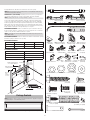 3
3
-
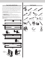 4
4
-
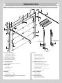 5
5
-
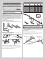 6
6
-
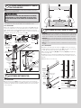 7
7
-
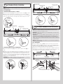 8
8
-
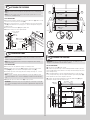 9
9
-
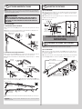 10
10
-
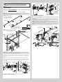 11
11
-
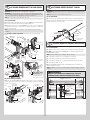 12
12
-
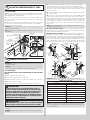 13
13
-
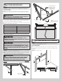 14
14
-
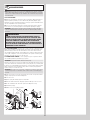 15
15
-
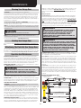 16
16
-
 17
17
-
 18
18
-
 19
19
-
 20
20
-
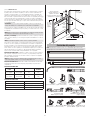 21
21
-
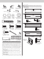 22
22
-
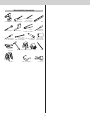 23
23
-
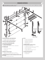 24
24
-
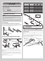 25
25
-
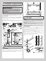 26
26
-
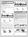 27
27
-
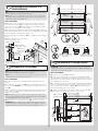 28
28
-
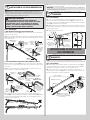 29
29
-
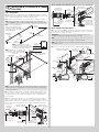 30
30
-
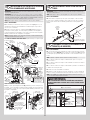 31
31
-
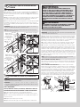 32
32
-
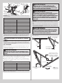 33
33
-
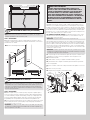 34
34
-
 35
35
-
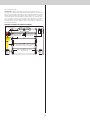 36
36
-
 37
37
-
 38
38


Wayne Dalton WD9100RW167 Guía de instalación
- Categoría
- Abridor de puerta de garage
- Tipo
- Guía de instalación
- Este manual también es adecuado para
en otros idiomas
Artículos relacionados

Otros documentos
-
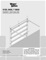 Wayne-Dalton Y 9600 Manual de usuario
-
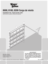 Wayne-Dalton 8000 Manual de usuario
-
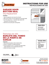 Frost King Vinyl Garage Door Bottom Weatherseal Replacement Guía de instalación
-
Everbilt 15441 Guía de instalación
-
 Wayne-Dalton 3324B-Z Manual de usuario
-
-
-
 Prime-Line U 10042 Instrucciones de operación
-
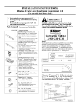 Clopay 4125477 Guía de instalación
-
Veranda 0214907002 Guía de instalación


