
SEISMIC DETECTOR
MODEL: RK66S
EN
EN
F
R
IT
CN
ES

2
INSTALLATION INSTRUCTIONS
INTRODUCTION
The RISCO Seismic Detector is used for the protection against break-in attempts of
vaults, safes, reinforced concrete walls, steel armored cabinets and doors. The
seismic detector monitors the vibration and temperature of a specific surface and
will react to all known types of intruder attacks, such as sledge hammers, diamond
head drills, explosives, hydraulic pressure tools and thermal tools.
The detector can operate both as a regular relay detector connected to any control
panel, or as a BUS accessory when connected to RISCO Group's control panels
via the RS485 BUS, empowering it with unique remote control and diagnostic
capabilities.
The instructions set forth below describe the RISCO seismic detector in Stand
Alone & BUS mode. For BUS installation programming, see RISCO System
installation manuals
Main Features:
Piezo sensor
Low/High temperature detection
Detection range up to 5 meters (16 feet) radius
Tamper protection
Anti drilling shield
Remote sensitivity control
Analogue signal output
Bar graph LED indicator
Remote self test
Stand-alone or RISCO BUS connection
INSTALLATION KIT
Each kit includes:
Wall structure fastening sets:
Expanding plugs M6 x 16
Flat head machining screw M6 X 16
Metallic structure fastening sets:
Inner Tooth Washer M4
Pan Head Machining Screw M4 X 10

3
External Test Generator
Detecto
r
Mounting Plate
PCB LAYOUT
Bar Graph LEDs Dipswitches
(default state) Terminal Blocks
Tamper EOL
Jumper Alarm EOL
Jumper Stand
Alone/BUS
Jumper
Tamper (Front ) External Test
Generator
Connector
Tamper (Back)
ON
1 2 3 4
ON
1 2 3 4
ON
1 2 3 4
+ 12V - YEL GRN NO C NC TAMPER SENS A.OUT TEST
Tamper EOL
Alarm EOL
S.A/ Bus
Ext. Test
LD1
LD2
LD3
LD4
LD5
LD6
LD7
LD8
LD9
J15
J13
J12
J2
1
2
3
4
5
6
8
7
SW1
SW2
SW3
SW4
SW5
SW6
SW7
SW8
SW9
SW10
SW11
SW12
9
1 2 3
4 5 6
7 8
(Mandatory
for surfaces
like concrete)
(not visible)

4
MOUNTING THE DETECTOR
Determine the mounting position. Potential false alarm sources must be
accounted for when installing RK66S, Therefore:
Attach the sensor to a surface as isolated as possible from extraneous
vibrations, with close contact between the concrete surface and the detector.
For metallic surfaces, remove residual paint from sensor installation site. Do
not use silicon grease between sensor and object!
For maximum vibration detection, the concrete surface should be smooth.
Use the mounting plate (see Figure 2) when mounting on drill-resistant steel,
brick or concrete surfaces. The plate can also be welded onto metallic
surfaces.
Adjust dipswitch settings for sensitivity; time and other parameters (see
Dipswitch settings, below) for background vibration – bearing in mind the
inverse relation between detection range and sensitivity and the construction
material of the object to be monitored. Detectors with high sensitivity can be
spaced up to 5m apart on secure protected surfaces (for example, steel),
confirmed by hammer or scratch tests.
Hinged doors, such as those on safes or ATM, and other attachments without
continuous acoustic transmission paths, should be protected with their own
detectors.
Remove the cover fixing screws to separate the cover from the base, see
Figure 1(A) / 2(B).
Drill holes on the mounting surface, using the detector base or mounting
plate as a guide, as follows:
Figure 1: Mounting the detector directly onto a metallic surface
Direct mounting on a metallic surface (Figure. 1)
a. Ensure that the mounting surface is level to within 1/128”
(0.1mm).
b. Use the detector base as a drilling template for the three holes
(3.2 mm dia.) and tap M4 thread at least ¼” (6 mm) deep.
Deburr threaded holes in metal.
c. Fit the detector using the supplied fixing screws, see Figure 1(B).

5
Figure 2: Mounting the detector using the mounting plate. (Note: Affix the mounting
plate using fixing screws or optionally, by welding the plate to a metallic surface.)
Installation using mounting plate (Figure 2):
a. (Optional metal welding) Weld the mounting plate along the two
provided vertical oblong cutout surfaces. Tap off slag and
remove weld splatter from the plate surface.
b. (On concrete) :
Never install the detector directly on a bare or plastered concrete
surface, since bending forces may cause damage to the seismic
sensor. Plaster of less than 10mm need not be removed.
i. Drill four holes for mounting plate (8 mm dia, min 35
mm depth for anchor; using a sintered carbide bit.
ii. Also, use the mounting plate as a drilling template
for the three threaded detector holes (5 mm dia) at
least 3 mm deep.
iii. Insert supplied metal plugs into drilled hole flush
with the concrete surface
iv. Ensure that the mounting plate is correctly
positioned. Press the mounting plate onto surface,
knock in screw with plug and tighten well. The plate
should not be capable of rotation.
v. Fit the detector using the supplied fixing screws, see
Figure 2(C).
c. (On metal) :
i. Use the mounting plate as a drilling template for the
four holes (5 mm dia.) and tap M6 thread at least 10
mm deep. Deburr threaded holes in metal.
ii. Also, use the mounting plate as a drilling template
for the three threaded detector holes (5 mm dia) at
least 3 mm deep.
iii. Affix the mounting plate with the supplied screws.
The plate should not be capable of rotation
iv. Fit the detector using the supplied fixing screws, see
Figure 2(C).
B
C

6
Connect wiring; Refer to Terminal Blocks section.
Set Jumpers; Refer to Jumper Selection section.
Set Dipswitches; Refer to Dipswitch Settings section.
To verify detector operation, perform:
a. A self test (See Testing the Detector section).
b. Sensitivity calibration using an external test generator (See
External Test Generator section).
Replace the cover and tighten the cover fixing screws; See Figure 1(A) / 2(B).
TERMINAL BLOCK LAYOUT
Figure 3: Terminal Block Layout
Terminal
Block Description
+12V (RED) Power supply positive (+) input voltage
- (BLK) Power supply negative (-) input voltage
YEL Used for data communication with RISCO panels (only for
BUS connection)
GRN Used for data communication with RISCO panels (only for
BUS connection)
NO Alarm Normally Opened relay output, 24VDC.0.1A
C Alarm Common relay output
NC Alarm Normally Closed relay output, 24VDC.0.1A
TAMPER N.C. Tamper Switch, 24VDC.0.1A
SENS Remote sensitivity control for lowering vibration sensitivity for
ATM-type dispensers when cash is being disbursed and
internal vibration generated.
GND = Low sensitivity
Not Connected = Reguler sensitivity
A.OUT Analog signal output: Connect a multimeter/scope or an
analogic tester between the A.OUT and -12V terminals, to
view the noise and signal voltage levels (in parallel to the LED
bar representation). In the absence of vibrations, the voltage
signal is 0V, and it increases as it detects vibrations.
If the voltage measured (in absence of vibrations) doesn't
remain stable but continues to increase, it means that
environmental noise is being captured and therefore the
detector sensitivity must be reduced.
TEST A short between TEST and GND activates the Remote Test
(see Dipswitch Settings 8 and 9).
(Not relevant for BUS mode.)

7
LED DISPLAY DURING NORMAL MODE
LED ON Colo
r
Severity Description
LD1 Red Temperature alarm
detection
LD2 Red
Vibration alarm
detection: Bar graph
(from LED8–2) indicating
signal power.
LD3 Yellow
LD4-8 Green
LD9 Green Power On
NOTE:
During Test mode the LED displays have a different meaning. Refer to the section:
Testin
g
the detector.
DIPSWITCH SETTINGS
STANDALONE MODE
Dipswitch Description (SW7 OFF)
SW1
SW2
SW3
Used to determine the detector's sensitivity. Sensitivity is a function
of coverage area and surface material.
SW1 SW2 SW3
*OFF *OFF *OFF
ON OFF OFF
OFF ON OFF
ON ON OFF
OFF OFF ON
ON OFF ON
OFF ON ON
ON ON ON
SW4 Used to detect single and extremely brief and intense signals
(including explosions and sledge hammers).
ON: Enable
*OFF: Disable
High
Sensitivity
Low
Sensitivity

8
Dipswitch Description (SW7 OFF)
SW5
SW6
Used to adjust the integration time. In combination with SW1-3 they
establish a threshold value; SW5-6 establishes a cumulative alarm
signal value which, when exceeding the threshold value, triggers
an alarm event.
SW5 SW6 Duration (in sec.)
*OFF *OFF 10 (example: vending machine)
ON OFF 26
OFF ON 46
ON ON 80 (example: bank vault)
SW7 Used to determine Stand Alone or BUS mode (Ensure that the J12
position (as below) matches the SW7 spec. )
ON: BUS
*OFF: Stand Alone
SW8
Used to determine Local or Remote Test
ON: Local. An internal self test is performed every 24 hours from
power-up. Test failure lights up the LEDs (see the Testing the
Detector section) and the LEDs remain lit until the next self test.
*OFF: Remote. A test is activated whenever the TEST input is
connected to GND. If the test passes, the alarm relay opens for
three seconds.
SW9
External test generator
ON: Enable External Test Generator
*OFF: Disable (internal test)
SW10
Used to enable the temperature sensor (alarm temperature
threshold of +85°C (+185°F))
ON: Enable *OFF: Disable (No temp. threshold is set)
SW11 Used to determine LEDs operation
ON: Enable *OFF: Disable
SW12 Not used
BUS MODE
Dipswitch Description
SW1-5 BUS Address
SW7 ON: BUS
SW6,8-12 Not Applicable
Low
Sensitivity
High
Sensitivity

9
JUMPER SELECTION
Jumpe
r
Function
S.A (Stand Alone) /BUS
J12
Used to enable tamper indication during Stand Alone
or BUS mode.
Stand Alone mode (Default).
BUS connection mode.
(See RISCO system programming manuals).
J13: Alarm EOL
J15: Tamper EOL
Jumpers J13 and J15 allow for the selection of Alarm
and Tamper resistance (1K, 2.2K, 4.7K, 5.6K and 6.8K)
according to the control panel. Follow the terminal block
connection diagram in Figure 4 when connecting the
detector to a Double End Of Line (DEOL) zone.
Figure 4: Schematic of EOL Resistors
Panel DEOL
TAMPER
ALARM
C NC TAMPER
NO
RESISTOR
(Default)
1K 2.2K 4.7K 5.6K 6.8K
TAMPER EOL JUMPERS (J15)
NO
RESISTOR
(Default)
1K 2.2K 4.7K 5.6K 6.8K
ALARM EOL JUMPERS (J13)

10
TESTING THE DETECTOR
RISCO recommends performing a self test after installation and before final cover
mounting. The test can be performed manually (locally or remotely) or automatically
every 24 hours
Remote self-test (Manual Test)
This test requires that a command be given in order to be performed.
To activate the remote self-test:
Ensure that the Dipswitch SW8 is set to OFF.
Short the TEST terminal block to GND.
All LEDs will turn on to indicate test commencement and sequentially turn off
after each successful parameter test.
The detector unit self test examines the following parameters:
LED Trouble
1 External power supply failure
2 Internal voltage faulty
4 Piezo sensor failure
5 Temperature sensor failure
3, 6-9 Not Applicable
All LEDs will turn off at the end of a successful test, except the POWER LED
(LED9) and the alarm relay opens for three seconds. If a malfunction occurs, one of
the LEDs remains lit.
Local self-test (Automatic Test)
Ensure that the Dipswitch SW8 is set to ON.
The RK66S detector runs a local/automatic SELF-TEST every 24 hours from the
time of initial power on. Test procedure and result presentation is as per the
Remote self-test above.
Front view Rear view

11
Attach to the concrete surface, using the supplied mounting screw in this hole
opening.
The external test generator can be used to:
Periodically verify proper functioning of the detector
Observe the detector’s sensitivity during installation
To use the test generator:
Connect the test generator to J2 on the PC board (with the polarity resulting
from the red wire connected to the plug pin closest to the terminal block, in
other words, the lowest)
Switch SW9 to ON.
Attach the test generator to the concrete surface.
Perform test, as follows:
a. For remote test, see the DIPSWITCH Settings section
b. For calibration test, Switch SW8 to ON and observe the LEDs
Specifications
In order to continue improving the product, RISCO Group reserves the right to
change specifications and/or designs without prior notice.
Ordering Information
Model Description
RK66S Seismic Detector
Coverage Up to 5 meters (16 feet) radius
Operating voltage 9 to 16 VDC
Current consumption Typically 20mA @ 12VDC
RFI immunity According to EN50130-4
Alarm contacts 24VDC, 0.1A, N/C and N/O
Tamper contacts 24VDC, 0.1A
Alarm contact hold time 2.5 seconds
Operating temperature -40°C to +70°C (-40°F to 158°F)
Storage temperature -50°C to +70°C (-58°F to 158°F)
Ingress protection (IP) rating IP43
Impact Rating IK08
RFI immunity According to EN50130-4
Dimensions (L x H x W) 102 X 27.5 X 80.2 mm
(4.0” X 1.1” X 3.2”)
Weight 220 g ( 7.7 oz)

12
NOTES

MICROFONO SELETTIVO
MODELLO: RK66S
ISTRUZIONI DI INSTALLAZIONE
IT

14
INTRODUZIONE
Il microfono selettivo di RISCO è utilizzato per la protezione di caveau, casseforti,
mura di cemento armato, armadi e porte blindate. Il microfono selettivo rileva la
vibrazione e la temperatura di una specifica superficie e reagisce a tutte le
tipologie di attacco conosciute come ad esempio punte di diamante, esplosivi, colpi
di mazza, lancia termica e dispositivi idraulici di pressione.
Il rivelatore può funzionare sia tramite connessione a relè ad una qualsiasi centrale
antifurto o tramite connessione BUS RS485 con le centrali antifurto RISCO. In
quest’ultimo caso il microfono selettivo può essere configurato e testato tramite
tastiera del sistema o tramite PC.
Le istruzioni che seguono descrivono il microfono selettivo RISCO sia nella
modalità a Relè che in quella BUS. Per il collegamento via BUS far riferimento
anche al manuale di installazione della centrale RISCO utilizzata.
Caratteristiche principali
Sensore piezoelettrico
Rilevazione temperatura Bassa/Alta
Portata fino a 2.5 metri di raggio
Protezione tamper
Schermo anti-perforazione
Controllo remoto della sensibilità
Uscita segnale analogico
Indicatore grafico a LED
Auto-test remoto
Collegamento a relè o via BUS RISCO
KIT DI INSTALLAZIONE
Ogni kit include:
Set di fissaggio comprendente:
Tasselli per viti M6 x 16
Viti a testa piatta tipo M6 X 16
Set metallico di fissaggio comprendente:
Rondella dentata per viti M4
Viti per metallo a testa cilindrica
tipo M4 X 10

15
Dispositivo esterno di test
Rivelatore
Piastra di fissaggio
DESCRIZIONE DELLA SCHEDA
Indicatori LED Microinterruttori
(default) Morsettiera
Ponticello
Tamper EOL Ponticello
Allarme EOL Ponticello
Relè/BUS
Tamper
(Apertura) Connettore Test
esterno
Tamper
(Rimozione)
ON
1 2 3 4
ON
1 2 3 4
ON
1 2 3 4
+ 12V - YEL GRN NO C NC TAMPER SENS A.OUT TEST
Tamper EOL
Alarm EOL
S.A/ Bus
Ext. Test
LD1
LD2
LD3
LD4
LD5
LD6
LD7
LD8
LD9
J15
J13
J12
J2
1
2
3
4
5
6
8
7
SW1
SW2
SW3
SW4
SW5
SW6
SW7
SW8
SW9
SW10
SW11
SW12
9
1 2 3
4 5 6
7 8
(Obbligatoria per
l’installazione su
superfici in cemento
armato)
(non visibile)

16
INSTALLAZIONE DEL RIVELATORE
Scegliere la posizione di installazione del microfono selettivo RK66S e tener
conto dei potenziali falsi allarmi per cui:
Posizionare il dispositivo su di una superficie quanto più immune possibile a
vibrazioni estranee e quanto più vicino possibile alla superficie da proteggere
se quest’ultima è in cemento armato. Per l’installazione su superfici
metalliche rimuovere da queste ultime eventuali residui di vernice. Non usare
assolutamente pasta di silicone tra il sensore e la superficie di installazione.
Per ottenere la migliore rilevazione di vibrazione possibile, le superfici di
installazione devono essere lisce. Utilizzare la piastra di montaggio (vedere
la Figura 2) quando si effettua l’installazione su di una superficie di mattoni,
calcestruzzo o su di una superficie metallica resistente al trapano. La piastra
di fissaggio può anche essere saldata sulle superfici metalliche.
Regolare tramite i microinterruttori la sensibilità, il tempo di intervento e gli
altri parametri (vedere la sezione Predisposizione dei microinterruttori).
Ricordare la relazione tra la sensibilità ed il materiale componente la
superficie da proteggere considerando che i microfoni configurati per un’alta
sensibilità possono essere distanziati fino a 5 metri dalla superficie da
proteggere (ad esempio quando la superficie dell’oggetto è di metallo) la cui
verifica può essere effettuata con l’utilizzo di un martello o sfregando la
superficie stessa.
Rimuovere le viti di fissaggio del coperchio per separare quest’ultimo dalla
base, vedere la Figura 1(A) / 2(B).
Forare la superficie di installazione usando la base del sensore o la piastra di
fissaggio come dima. Procedere come segue:
Figura 1: Installazione del microfono selettivo direttamente su di una superficie
metallica

17
Installazione diretta su di una superficie metallica (Figura. 1)
a. Assicurarsi che la superficie di fissaggio sia in piano entro
0.1mm.
b. Usare la base del sensore come dima per fare tre fori (da 3.2
mm dia.) e profondi almeno 6 mm per le viti M4. Eliminare le
eventuali sbavature provocate dalla foratura del metallo.
c. Fissare il microfono selettivo utilizzando le viti fornite, vedere la
Figura 1(B).
Figura 2: Installazione del microfono selettivo utilizzando la piastra di fissaggio.
(Nota: Fissare la piastra utilizzando le viti di fissaggio o, opzionalmente, saldando la
piastra se la superficie da proteggere è metallica).
Installazione utilizzando la piastra di fissaggio (Figura 2):
d. (Saldatura sul metallo) Saldare la piastra di montaggio lungo le
due aperture verticali alla superficie da proteggere. Rimuovere
dalla superficie della piastra le sbavature di stagno e gli
eventuali detriti.
e. (Installazione sul calcestruzzo) :
Non installare mai il microfono selettivo direttamente sul
cemento a vista o intonacato poiché le eventuali flessioni della
superficie possono danneggiare l’unità. L’intonaco minore di
10mm non deve essere rimosso.
i. Realizzare 4 fori per la piastra di fissaggio (8 mm
dia., min. 35 mm di profondità per tassello) usando
una punta specifica per il calcestruzzo.
ii. Usare la piastra di fissaggio come dima per
realizzare i 3 fori da 5 mm di diametro e almeno 3
mm di profondità per il fissaggio del sensore sulla
piastra.
iii. Inserire i tasselli in metallo in dotazione a filo foro
con la superficie del calcestruzzo.
B
C

18
iv. Assicurarsi che la piastra di installazione sia
posizionata correttamente. Spingere la piastra
contro la parete, , spingere le vite con il tassello e
stringerle bene. La piastra non deve avere alcuna
possibilità di movimento.
v. Fissare il rivelatore utilizzando le viti fornite, vedere
la Figura 2(C).
f. (Installazione sul metallo) :
i. Usare la piastra di fissaggio come dima per
realizzare i 3 fori da 5 mm di diametro e almeno 10
mm di profondità per le viti M6. Eliminare le
eventuali sbavature provocate dalla foratura del
metallo.
ii. Usare ancora la piastra di fissaggio come dima per
realizzare i 3 fori da 5 mm di diametro e almeno 3
mm di profondità per il fissaggio del sensore sulla
piastra.
iii. Fissare la piastra di montaggio con le viti fornite. La
piastra non deve avere alcuna possibilità di
movimento.
iv. Fissare il rivelatore utilizzando le viti fornite, vedere
la Figura 2(C).
Cablaggio; far riferimento alla sezione Morsettiera.
Impostare i ponticelli; far riferimento alla sezione Predisposizione dei
ponticelli.
Impostare i microinterruttori; far riferimento alla sezione Predisposizione
microinterruttori.
Per verificare il funzionamento del microfono selettivo procedere come
segue:
a. Auto-test (Vedere la sezione Test del rivelatore).
b. Calibrazione della sensibilità tramite dispositivo di test esterno
(Vedere la sezione Dispositivo esterno di test ).
Riposizionare il coperchio e stringere le viti di fissaggio, vedere la Figura 1(A)
/ 2(B).

19
MORSETTIERA
Figura 3: Morsettiera
Morsetti Descrizione
+12V (RED) Ingresso positivo di alimentazione (+)
- (BLK) Ingresso negativo di alimentazione (-)
YEL Usato per la comunicazione via BUS con le centrali RISCO
GRN Usato per la comunicazione via BUS con le centrali RISCO
NO Uscita a relè normalmente aperta, 24Vcc. 0.1A
C Riferimento comune del relè
NC Uscita a relè normalmente chiusa, 24VDC.0.1A
TAMPER Uscita Tamper N.C. , 24Vcc. 0.1A
SENS Controllo remoto della sensibilità (usato per diminuire la
sensibilità per i Bancomat che, quando erogano il denaro
contante, generano una vibrazione interna).
GND = Bassa sensibilità
Non collegato = sensibilità Reguler
A.OUT Uscita segnale analogico: usato per connettere un multimetro
o un tester analogico tra questo morsetto A.OUT e il morsetto
-12V, tramite il quale rilevare i valori di rumore e di segnale
(valori riportati anche tramite la scala LED) . In assenza di
vibrazioni il livello di segnale deve essere 0 Volt e aumentare
se rileva vibrazioni.
TEST Applicare un negativo (0V) a questo ingresso quando si
richiede una sensibilità minore, in caso contrario applicare
una tensione (+12V) o lasciare l’ingresso non connesso.

20
DISPLAY LED NEL NORMALE FUNZIONAMENTO
LED ON Colore Gravità Descrizione
LD1 Rosso Rilevazione allarme
temperatura
LD2 Rosso
Rilevazione allarme
vibrazione: La scala LED
(LED da 8 a 2) indicano
il livello di segnale.
LD3 Giallo
LD4-8 Verde
LD9 Verde Alimentazione
NOTA:
Nella modalità Test il display a LED ha una funzione differente. Fare riferimento alla
sezione: Test del microfono selettivo.
PREDISPOSIZIONE MICROINTERRUTTORI
Modalità a Relè
Microint. Descrizione (SW7 OFF)
SW1
SW2
SW3
Usato per impostare la sensibilità del rivelatore.
La sensibilità dipende dall’area e al materiale della superficie ove è
fissato il rivelatore.
SW1 SW2 SW3
*OFF *OFF *OFF
ON OFF OFF
OFF ON OFF
ON ON OFF
OFF OFF ON
ON OFF ON
OFF ON ON
ON ON ON
SW4 Usato per rilevare segnali estremamente corti ed intensi (incluso
esplosioni e colpi di mazza).
ON: Abilitato
*OFF: Disabilitato
Alta
sensibilità
Bassa
sensibilità

21
Microint. Descrizione (SW7 OFF)
SW5
SW6
Questi microinterruttori vengono usati per regolare il tempo di
integrazione.
Mentre i microinterruttori SW1-3 stabiliscono una soglia di allarme,
SW5-6 definiscono la persistenza del segnale che, se supera la
soglia definita, attiva l’evento di allarme
SW5 SW6 Durata
(
in sec.
)
*OFF *OFF 10 (es.: distributore
automatico
)
ON OFF 26
OFF ON 46
ON ON 80
(
es.: caveau della banca
)
SW7 Utilizzato per selezionare la modalità di funzionamento a Relè o
BUS (Verificare che il ponticello J12 riportato in seguito sia nella
corretta posizione per la modalità scelta)
ON: BUS
*OFF: Relè
SW8
Utilizzato per l’auto test interno locale o remoto.
ON: Locale. Ogni 24 ore viene eseguito un test automatico interno a
partire dalla prima alimentazione del sensore. Se il test fallisce
vengono accesi i LED (vedere la sezione Test del rivelatore) che
rimangono attivi fino al test successivo.
*OFF: Remoto. L’auto test del sensore viene effettuato quando al
morsetto TEST viene applicato un riferimento negativo di
alimentazione GND. Se il test non rileva nessun problema, il relè di
allarme si attiva per tre secondi.
SW9
Dispositivo esterno di test (vedere pagina 13)
ON: Dispositivo esterno di test abilitato
*OFF: Dispositivo esterno di test disabilitato (test interno)
SW10
Usato per abilitare il sensore di temperatura (soglia temperatura di
allarme +85°C)
ON: Abilitato
*OFF: Disabilitato (Nessuna impostazione di soglia temperatura)
SW11
Configura il funzionamento dei LED
ON: Abilitati
*OFF: Disabilitati
SW12 Non usato
* Default
Bassa
sensibilità
Alta
sensibilità

22
Modalità BUS
Microint. Descrizione
SW1-5 Indirizzo ID BUS
S
W
7 ON: BUS
SW6,8-12 Non Applicabile
PREDISPOSIZIONE PONTICELLI
Ponticello Funzione
S.A (Relè) / BUS
J12
Usato per gestire la segnalazione di tamper nelle
modalità BUS e Relè.
Modalità Relè (Default)
Modalità BUS.
(Vedere i manuali di
programmazione dei sistemi
RISCO)
J13: EOL Allarme
J15: EOL Tamper
I ponticelli J13 e J15 configurano il valore resistivo
delle uscite di allarme e tamper (1K, 2.2K, 4.7K, 5.6K
e 6.8K) in riferimento alla centrale utilizzata. Seguire
lo schema di collegamento della Figura 4 per
collegare il rivelatore ad una zona in doppio
bilanciamento resistivo (DEOL).

23
Figura 4: Schema resistenze EOL
IMQ Nota: l'uso di un contatto di allarme N / O annulla la certificazione IMQA.
AUTO TEST DEL RIVELATORE
RISCO consiglia di effettuare un test interno dopo l’installazione, prima del
montaggio definitivo del coperchio. Il test può essere effettuato manualmente
(localmente o in remoto) o automaticamente ogni 24 ore.
Auto test remoto (Test manuale)
Questo test richiede un comando di attivazione per essere eseguito.
Per attivare l’auto test remoto procedere come segue:
Controllare che il microinterruttore SW8 sia in OFF.
Cortocircuitare il morsetto TEST con il GND.
Tutti i LED si illumineranno evidenziando l’inizio del test e in sequenza si
spegneranno dopo che ogni parametro a cui fanno riferimento è stato
verificato correttamente funzionante.
L’auto test è in grado di rilevare le eventuali anomalie seguenti:
LED
A
nomalia
1 Guasto alimentazione esterna
2 Guasto di alimentazione interno
4 Guasto sensore piezo
5 Guasto sensore di temperatura
3, 6-9 Non usati
Dopo che il test non ha evidenziato guasti, tutti i LED si spegneranno tranne il
LED POWER (LED 9) di alimentazione. A conferma del buon esito del test il relè di
allarme si aprirà per tre secondi.

24
Auto Test locale (Test automatico)
Controllare che il microinterruttore SW8 sia in ON.
Il microfono selettivo RK66S avvia un auto test locale/automatico ogni 24 ore a
partire dall’alimentazione iniziale. La procedura di test e la rappresentazione e del
risultato è la stessa dell’auto test remoto come descritto nel paragrafo precedente
Auto Test Remoto (Test manuale).
Dispositivo esterno di test
Vista frontale Vista posteriore
Fissare il dispositivo sulla superficie di calcestruzzo utilizzando la vite fornita per
l’apposito foro illustrato nell’immagine sopra.
Il dispositivo esterno di test può essere usato per:
Verificare periodicamente la corretta rilevazione del microfono
Verificare la sensibilità nella fase di installazione
Come utilizzare il dispositivo di test:
Connettere il dispositivo di test al connettore J2 posizionato sulla scheda
elettronica (posizionare il filo rosso nella parte bassa del connettore, quella
vicino alla morsettiera)
Impostare il microinterruttore SW9 su ON.
Fissare il dispositivo di test alla superficie da proteggere.
Effettuare il test come segue:
a. Per il test remoto fare riferimento alla sezione Predisposizione
microinterruttori
b. Per il test di calibrazione posizionare il microinterruttore SW8 in
ON e osservare il comportamento dei LED.

25
Specifiche tecniche
Informazioni per l'ordinazione
Modello Descrizione
RK66S Microfono selettivo
Copertura Fino a 2.5 metri di raggio
Tensione operativa Da 9 a 16 Vcc
Assorbimento di corrente 20mA @ 12Vcc
Immunità RFI Conforme alla EN50130-4
Contatti di allarme 24Vcc, 0.1A, N/C e N/O
Contatti Tamper 24Vcc, 0.1A
Tempo di ritenuta dei contatti 2.5 secondi
Temperatura di funzionamento Da +5°C a +40°C
Temperatura di stoccaggio Da -50°C to +70°C
Grado di protezione IP IP43
Grado di protezione contro l’impatto IK08
Dimensioni (L x H x W) 102 X 27.5 X 80.2 mm
Peso 220 g
Approvazione Livello II (CEI 79-2)

26
NOTES

DETECTEUR SISMIQUE
MODELE: RK66S
MANUEL D’INSTALLATION
F
R

28
INTRODUCTION
Le détecteur sismique RISCO est utilisé pour la protection contre les tentatives
d'effraction des salles fortes, coffre-fort, murs en béton armé, armoires en acier et
portes blindées. Le détecteur sismique surveille la vibration et la température d'une
surface spécifique et va réagir à tous les types connus d'attaques d'intrusion,
comme des marteaux, perceuses à tête de diamant, explosifs, outils de pression
hydraulique et outils thermiques.
Le détecteur peut fonctionner à la fois comme un détecteur à relais standard
connecté à une centrale d’alarme, ou comme un accessoire BUS lorsqu'il est
connecté aux centrales de RISCO Group via le bus RS485, lui apportant un
contrôle à distance unique et des capacités de diagnostic.
Les instructions énoncées ci-dessous décrivent le détecteur sismique RISCO en
mode Autonome & en mode BUS. Pour la programmation de l'installation BUS,
veuillez consulter les manuels d'installation du système RISCO.
Caractéristiques principales:
• Capteur piézo-électrique
• Détection de la température basse / haute
• Portée de détection jusqu'à 5 mètres de rayon
• Protection contre les sabotages
• Bouclier anti-perçage
• Contrôle de la sensibilité à distance
• Signal de sortie analogique
• Indicateur graphique à barres LED
• Autotest à distance
• Autonome ou RISCO connexion BUS
KIT d’INSTALLATION
Chaque kit comprend:
Ensemble de fixation sur support
mural:
Chevilles expansibles M6 x 16
Vis à tête plate pour visseuse M6 X 16
Ensemble de fixation sur support
métallique:
Rondelle dentelée M4
Vis pour visseuse M4 X 10

29
Générateur de Test Externe
Détecteu
r
Plaque de Montage
DISPOSITION CARTE
Bar Graphe à LEDs Dip switches
(position par
défaut)
Bornier de
raccordement
Cavaliers EOL
Autoprotection
Cavaliers EOL
Alarme Cavaliers
Autonome/BUS
Autoprotection
(Ouverture)
Connecteur du
générateur de
test externe
Autoprotection
(Arrachement)
ON
1 2 3 4
ON
1 2 3 4
ON
1 2 3 4
+ 12V - YEL GRN NO C NC TAMPER SENS A.OUT TEST
Tamper EOL
Alarm EOL
S.A/ Bus
Ext. Test
LD1
LD2
LD3
LD4
LD5
LD6
LD7
LD8
LD9
J15
J13
J12
J2
1
2
3
4
5
6
8
7
SW1
SW2
SW3
SW4
SW5
SW6
SW7
SW8
SW9
SW10
SW11
SW12
9
1 2 3
4 5 6
7 8
(Obligatoire
pour les
surfaces
comme le
béton)
(non visible)

30
MONTAGE DU DETECTEUR
Déterminer la position de montage. Les sources de fausses alarmes
potentielles doivent être prises en compte lors de l'installation RK66S, donc:
Fixer le capteur sur une surface aussi isolée que possible des vibrations
parasites, en assurant un contact étroit entre la surface du béton et le
détecteur. Pour les surfaces métalliques, enlever les restes de peinture sous
la surface du capteur. Ne pas utiliser de graisse silicone entre le capteur et
l'objet !
Pour une détection maximale des vibrations, la surface en béton doit être
lisse. Utilisez la plaque de montage (voir la figure 2) lors du montage des
surfaces en acier résistante au perçage, en brique ou en béton. La plaque
peut également être soudée sur des surfaces métalliques.
Ajuster les paramètres des commutateurs DIP comme la sensibilité; les
temporisations et autres paramètres (voir réglages des commutateurs DIP,
ci-dessous) pour les vibrations arrière - en gardant à l'esprit la relation
inverse entre la zone de détection et la sensibilité et le matériau de
construction de l'objet à surveiller. Les détecteurs en haute sensibilité
peuvent être espacés jusqu'à 5m sur les surfaces protégées sécurisés (par
exemple, acier), confirmé par des tests au marteau ou grattage.
Les portes à charnières, telles que celles sur un coffre-fort ou DAB, et autres
dispositifs sans voies de transmission acoustiques continus, doivent être
protégés par leurs propres détecteurs.
Retirer les vis de fixation du couvercle et séparer le couvercle de la base, voir
Figure 1(A) / 2(B).
Percez des trous sur la surface de montage, en utilisant la base de détecteur
ou la plaque de montage comme gabarit, comme suit:
Figure 1: Montage du détecteur directement sur une surface métallique

31
Montage direct sur une surface métallique (Figure. 1)
a. Assurez-vous que la surface de montage est de niveau à
0.1mm.
b. Utiliser la base de détecteur en tant que gabarit de perçage pour
les trois trous (3.2 mm dia.) et faire un filetage M4 sur 6 mm de
profondeur au minimum. Ebavurez les trous métalliques filetés.
c. Monter le détecteur à l'aide des vis de fixation fournies, voir
Figure 1(B).
Figure 2: Montage du détecteur à l'aide de la plaque de montage. (Remarque: Fixer la
plaque de montage au moyen de vis de fixation ou éventuellement, par soudage de la
plaque sur une surface métallique.)
Installation à l'aide de la plaque de montage (Figure 2):
a. (Option soudage des métaux) Souder la plaque de montage sur
les deux oblongs verticaux découpés prévus. Enlever les
éclaboussures de soudure de la surface de la plaque.
b. (Sur du béton) :
Ne jamais installer le détecteur directement sur une surface de
béton nu ou plâtré, car des forces de flexion peuvent
endommager le capteur sismique. Le plâtre de moins de 10 mm
n'a pas besoin d'être retiré.
i. Percez quatre trous pour la plaque de montage
(diamètre 8mm, min 35 mm profondeur pour
fixation; en utilisant une mèche carbure).
ii. Utilisez la plaque de montage comme gabarit de
perçage pour les trois trous filetés de détection (5
mm de diamètre) d’au moins 3 mm de profondeur.
iii. Insérer les embouts métalliques fournis dans les
trous percés au ras de la surface du béton
iv. Assurez-vous que la plaque de montage est
correctement positionnée. Appliquer la plaque de
montage sur la surface, frapper la vis avec embout
et serrer bien. La plaque ne doit pas être capable de
tourner.

32
v. Monter le détecteur à l'aide des vis de fixation
fournies, voir Figure 2(C).
c. (Sur du métal) :
i. Utilisez la plaque de montage comme gabarit de
perçage pour les quatre trous (diamètre 5 mm) et
enfoncer le filetage M6 d’au moins 10 mm de
profondeur. Ebavurez trous métalliques filetés.
ii. Utilisez la plaque de montage comme gabarit de
perçage pour les trois trous filetés de détection
(diamètre 5 mm) d’au moins 3 mm de profondeur.
iii. Fixez la plaque de montage avec les vis fournies.
La plaque ne doit pas être capable de tourner.
iv. Monter le détecteur à l'aide des vis de fixation
fournies, voir Figure 2(C).
Connecter le fils; Reportez-vous à la section Borniers.
Réglez les cavaliers; Reportez-vous à la section de sélection des cavaliers.
Réglez les commutateurs DIP; Reportez-vous à la section Paramètres
commutateurs DIP.
Pour vérifier le fonctionnement du détecteur, effectuer:
c. Un autotest (Voir la section test du détecteur).
a. Un calibrage de la sensibilité à l'aide d'un générateur de test
externe (voir la section du générateur de test externe).
Replacez le couvercle et serrez les vis de fixation du couvercle; voir Figure
1(A)/2(B).
DISPOSITION BORNIER
Figure 3: Disposition Bornier
Bornie
r
Description
+12V (RED) Alimentation positive (+) tension d'entrée
- (BLK) Alimentation négative (-) tension d'entrée
YEL Utilisé pour les communications de données avec les
centrales RISCO (uniquement pour la connexion BUS)
GRN Utilisé pour les communications de données avec les
centrales RISCO (uniquement pour la connexion BUS)
NO Sortie Alarme relais normalement ouvert, 24VDC.0.1A
C Sortie Alarme Commun relais
NC Sortie Alarme relais normalement fermé, 24VDC.0.1A
AUTOPROTECTION N.F. Inter. Autoprotection, 24VDC.0.1A

33
Bornie
r
Description
SENS Contrôle de la sensibilité à distance pour diminuer la
sensibilité aux vibrations pour les distributeurs de billets
lors du chargement ou lorsque d’une vibration interne est
générée.
GND = Sensibilité Faible
Non Connecté = Sensibilité normale
A.OUT Sortie Signal analogique: Branchez un
multimètre/Oscilloscope ou un testeur analogique entre
le A.OUT et la borne -12V, pour visualiser le niveau de
tension du signal de bruit (en parallèle à la visualisation
sur le barrre graphe à LED). En l'absence de vibration, la
tension du signal est de 0V, et elle augmente avec la
détection des vibrations.
Si la tension mesurée (en l'absence de vibrations) ne
reste pas stable, mais continue d'augmenter, cela
signifie qu’un bruit ambiant est capté et par conséquent
la sensibilité du détecteur doit être réduite.
TEST Un court-circuit entre TEST et GND active le test à
distance (voir Paramètres commutateur DIP 8 et 9).
(Non significatif en mode BUS.)
AFFICHAGE LED en mode NORMAL
LED ALLUMEE Couleu
r
Sévérité Description
LD1 Rouge Détection Alarme
Température
LD2 Rouge
Alarme détection
Vibration: Barre graphe
(à partir de LED8–2)
indiquant la puissance
du signal.
LD3 Jaune
LD4-8 Vert
LD9 Vert Alimenté
NOTE:
En mode test, les écrans LED ont une signification différente. Reportez-vous à la
section: Test du détecteur

34
REGLAGES Dipswitch
MODE AUTONOME
Dip
Switch Description (SW7 OFF)
SW1
SW2
SW3
Permet de déterminer la sensibilité du détecteur. La sensibilité est
fonction de la zone de couverture et de la surface du matériau.
SW1 SW2 SW3
*OFF *OFF *OFF
ON OFF OFF
OFF ON OFF
ON ON OFF
OFF OFF ON
ON OFF ON
OFF ON ON
ON ON ON
SW4 Utilisé pour détecter des signaux uniques et très brefs et intenses (y
compris les explosions et les marteaux piqueurs).
ON: Validé
*OFF: Dévalidé
SW5
SW6
Permet de régler le temps d'intégration. En combinaison avec SW1-
3, ils établissent une valeur de seuil; SW5-6 établit une valeur de
signal d'alarme cumulative qui, lors du dépassement de la valeur de
seuil, déclenche un événement d'alarme.
SW5 SW6 Durée (en sec.)
*OFF *OFF 10 (exemple: distributeur
automatique)
ON OFF 26
OFF ON 46
ON ON 80 (exemple: coffre de banque)
SW7 Utilisé pour déterminer, le mode autonome ou BUS (Assurez-vous
que la position de J12 (ci-dessous) correspond à la spécification
SW7.
ON: BUS
*OFF: Autonome
SW8
Utilisé pour déterminer test local ou distant
ON: Local. Un autotest interne est effectué toutes les 24 heures à
partir de la mise sous tension. Un échec du test allume les LED’s
(voir la section Test de détection) et les voyants restent allumés
jusqu'à l'autotest suivant.
*OFF: Distant. Un test est activé chaque fois que l'entrée de test est
connectée à GND. Si le test réussit, le relais d'alarme s'ouvre
pendant trois secondes.
Haute
Sensibilité
Faible
Sensibilité
Haute
Sensibilité

35
Dip
Switch Description (SW7 OFF)
SW9
Générateur de test externe
ON: Valide le Générateur de test externe
*OFF: Dévalidé (test interne)
SW10
Utilisé pour valider le détecteur de température (seuil de température
d'alarme de 85°C
ON: Validé *OFF: Dévalidé (Pas de température. Le seuil est fixe)
SW11 Utilisé pour déterminer le fonctionnement des LED
ON: Validé *OFF: Dévalidé
SW12 Non Utilisé
MODE BUS
Dip Switch Description
SW1-5 Adresse BUS
SW7 ON: BUS
SW6,8-12 Non Applicable

36
CAVALIERS de SELECTION
Cavaliers Fonction
S.A (Autonome)/BUS
J12
Permet d'activer l'indication de sabotage dans les
modes autonome ou BUS.
Mode Autonome (Défaut).
Mode connexion BUS.
(Voir les manuels de
programmation du système
RISCO).
J13: EOL Alarme
J15: EOL
Autoprotection
Les cavaliers J13 et J15 permettent la sélection des
résistances de fin de linge d’alarme et sabotage (1K,
2.2K, 4.7K, 5.6K et 6.8K) en fonction de la centrale.
Suivre le schéma de connexion par bornier à la figure
4 lors de la connexion d’une zone de détection avec
une double résistance de fin de ligne (DEOL)..
Figure 4: Schéma des Résistances de fin de ligne
Panel DEOL
TAMPER
ALARM
C NC TAMPER
NO
RESISTOR
(Default)
1K 2.2K 4.7K 5.6K 6.8K
TAMPER EOL JUMPERS (J15)
NO
RESISTOR
(Default)
1K 2.2K 4.7K 5.6K 6.8K
ALARM EOL JUMPERS (J13)

37
TEST DU DETECTEUR
RISCO recommande d'effectuer un autotest après l'installation et avant la fermeture
du capot. Le test peut être effectué manuellement (localement ou à distance) ou
automatiquement toutes les 24 heures.
Autotest à distance (Test Manuel)
Ce test nécessite une commande pour être exécuté.
Pour activer l'autotest à distance:
Assurez-vous que le commutateur DIP SW8 est réglé sur OFF.
Relier la borne TEST à GND.
Tous les voyants s'allument pour indiquer le début du test et s’éteignent
séquentiellement après chaque test réussi.
L'autotest de l'unité de détection examine les paramètres suivants:
LED Trouble
1 Panne d'alimentation externe
2 Tension interne défectueuse
4 Défaillance du capteur piézo-électrique
5 Défaillance du capteur de température
3, 6-9 Non Applicable
Tous les voyants s'éteignent à la fin d'un test réussi, sauf la LED POWER (LED9)
et le relais d'alarme s'ouvre pendant trois secondes. En cas de dysfonctionnement,
une des LED reste allumée.
Autotest Local (Test Automatique)
Assurez-vous que le commutateur DIP SW8 est réglé sur ON.
Le détecteur RK66S lance un Autotest automatique local toutes les 24 heures à
partir de sa mise sous tension initiale. La Procédure de test et le résultat est
similaire à l'autotest distant ci-dessus.
Vue de face Vue arrière

38
Fixer le testeur à la surface en béton, à l'aide de la vis de fixation fournie dans
l’ouverture prévue à cet effet.
Le générateur de test extérieur peut être utilisé pour:
Vérifier périodiquement le bon fonctionnement du détecteur
Observer la sensibilité du détecteur lors de l’installation
Pour utiliser le générateur de test:
Connecter le générateur de test à J2 sur la carte du circuit imprimé (avec la
polarité du fil rouge reliée à la broche de la prise la plus proche du bornier, en
d'autres termes, la plus basse)
Switch SW9 sur ON.
Fixer le générateur de test à la surface du béton.
Effectuer un essai, comme suit:
c. Pour l'essai à distance, voir la section Paramètres Dipswitch
a. Pour le test d'étalonnage, Switch SW8 sur ON et observer les
LED
Spécifications
Afin de continuer à améliorer le produit, RISCO Group se réserve le droit de
modifier les spécifications et / ou la conception sans préavis.
Information de commande
Modèle Description
RK66S Détecteur Sismique
Couverture Jusqu'à 5 mètres de rayon
Tension d’Alimentation 9 à 16V DC
Consommation 20mA Typique @ 12VDC
Immunité RFI Conforme à EN50130-4
Contacts d’Alarme 24V DC, 0.1A, N/F et N/O
Contacts d’Autoprotection 24V DC, 0.1A
Temps de maintien du contact
d’alarme
2.5 secondes
Température de
fonctionnement
-40°C à +70°C
Température de Stockage -50°C à +70°C
Indice de protection (IP) IP43
Note d'impact IK08
Dimensions (L x H x P) 102 X 27.5 X 80.2 mm
Poids 220 g

DETECTOR SÍSMICO
MODELO: RK66S
INSTRUCCIONES DE INSTALACIÓN
ES

40
INTRODUCCIÓN
El Detector sísmico RISCO se utiliza para la protección contra intentos de robo de
cámaras acorazadas, cajas fuertes, paredes de hormigón reforzado, y armarios y
puertas acorazadas de acero. El detector sísmico controla la vibración y la
temperatura de una superficie específica y reaccionará a todos los tipos conocidos
de ataques de intrusos, como martillos, taladros de diamante, explosivos,
herramientas de presión hidráulica y herramientas térmicas.
El detector puede funcionar tanto como un detector de relé normal conectado a
cualquier central, como un accesorio de BUS cuando se conecta a las centrales de
RISCO Group a través del BUS RS485, lo que le brinda capacidades únicas de
diagnóstico y control remoto.
Las instrucciones que se detallan a continuación describen el detector sísmico
RISCO en modo Independiente y BUS. Para la programación de la instalación del
BUS, consulte los manuales de instalación de los sistemas RISCO.
Características principales:
Sensor piezoeléctrico
Detección de temperatura alta/baja
Radio de detección de hasta 5 metros
Tamper de protección
Protección antitaladros
Control remoto de la sensibilidad
Salida de señal analógica
Barra de indicadores LED
Autotest remoto
Conexión en modo Independiente o modo RISCO BUS
KIT DE INSTALACIÓN
Cada kit incluye:
Elementos de fijación de
estructura de pared:
Tacos de expansión M6 x 16
Tornillo mecanizado de cabeza plana M6 X 16
Elementos de fijación de
estructura metálica:
Arandela dentada interna M4
Tornillo mecanizado de cabeza plana M4 X 10

41
Generador de test externo
Detecto
r
Placa de montaje
DESCRIPCIÓN DE LA PLACA
Barra de LED Microinterruptores
(por defecto) Terminal de
conexiones
Puente
Tamper RFL Puente Alarma
RFL Puente
Independiente/BUS
Tamper
frontal Conector
Generador de test
externo
Tamper trasero
ON
1 2 3 4
ON
1 2 3 4
ON
1 2 3 4
+ 12V - YEL GRN NO C NC TAMPER SENS A.OUT TEST
Tamper EOL
Alarm EOL
S.A/ Bus
Ext. Test
LD1
LD2
LD3
LD4
LD5
LD6
LD7
LD8
LD9
J15
J13
J12
J2
1
2
3
4
5
6
8
7
SW1
SW2
SW3
SW4
SW5
SW6
SW7
SW8
SW9
SW10
SW11
SW12
9
1 2 3
4 5 6
7 8
(Obligatorio
para
superficies
como
hormigón)
(no visible)

42
MONTAJE DEL DETECTOR
Determine la posición de montaje. Deben tenerse en cuenta las posibles
fuentes de falsas alarmas al instalar el RK66S, por lo tanto:
Conecte el sensor a una superficie lo más aislada posible de vibraciones
extrañas, con contacto cercano entre la superficie de hormigón y el detector.
En el caso de superficies metálicas, retire la pintura residual del sitio de
instalación del sensor. ¡No utilice grasa de silicona entre el sensor y el
objeto!
Para lograr la máxima detección de vibraciones, la superficie de hormigón
debe ser lisa. Use la placa de montaje (consulte la Figura 2) si la instalación
se realiza en superficies de acero, ladrillo u hormigón resistentes a la
perforación. La placa también puede soldarse sobre superficies metálicas.
Ajuste los microinterruptores para configurar la sensibilidad, el tiempo y otros
parámetros (consulte la sección de configuración de microinterruptores a
continuación) para la vibración de fondo, teniendo en cuenta la relación
inversa entre el rango de detección y la sensibilidad y el material de
construcción del objeto que se va a controlar. Los detectores con alta
sensibilidad pueden separarse hasta 5 m en superficies seguras protegidas
(por ejemplo, acero), confirmadas por pruebas de martillos o rasguños.
Las puertas batientes, como las de cajas fuertes o cajeros automáticos, y
otros accesorios sin vías de transmisión acústica continua deben protegerse
con sus propios detectores.
Retire los tornillos de fijación de la tapa para separar la tapa de la base.
Consulte la Figura 1(A)/2(B).
Perfore orificios en la superficie de montaje de la siguiente manera utilizando
la base del detector o la placa de montaje como guía:
Figura 1: Montaje del detector directamente sobre una superficie metálica

43
Montaje directo sobre una superficie metálica (Figura 1)
a. Asegúrese de que la superficie de montaje esté nivelada a
0,1 mm.
b. Utilice la base del detector como plantilla de perforación para los
tres orificios (3,2 mm de diámetro) e introduzca la rosca M4 al
menos a 6 mm de profundidad. Desbarbe los orificios roscados
en el metal.
c. Ajuste el detector con los tornillos de fijación suministrados.
Consulte la Figura 1(B).
Figura 2: Montaje del detector con la placa de montaje. (Nota: Fije la placa de
montaje utilizando tornillos de fijación o, si lo desea, soldando la placa a una
superficie metálica.)
Instalación con placa de montaje (Figura 2):
g. (Soldadura opcional) Suelde la placa de montaje a lo largo de
las dos superficies de corte verticales provistas. Quite la
suciedad y retire las salpicaduras de soldadura de la superficie
de la placa.
h. (En hormigón):
Nunca instale el detector directamente sobre una superficie de
hormigón sin revestimiento o enlucida, ya que las fuerzas de
flexión podrían dañar el sensor sísmico. No es necesario retirar
el yeso de menos de 10 mm.
i. Taladre cuatro orificios para la placa de montaje
(8 mm de diámetro, mín. 35 mm de profundidad
para anclajes) con una broca de carburo
sinterizado.
ii. Además, use la placa de montaje como plantilla de
perforación para los tres orificios roscados del
detector (5 mm de diámetro) al menos con 3 mm de
profundidad.
iii. Inserte los tapones de metal provistos en el orificio
perforado al ras con la superficie de hormigón.
B
C

44
iv. Asegúrese de que la placa de montaje esté
colocada correctamente. Presione la placa de
montaje sobre la superficie, golpee el tornillo con el
taco y apriételo bien. La placa no debe poder girar.
v. Ajuste el detector con los tornillos de fijación
suministrados. Consulte la Figura 2(C).
i. (En metal):
i. Utilice la placa de montaje como plantilla de
perforación para los cuatro orificios (5 mm de
diámetro) e introduzca la rosca M6 al menos a
10 mm de profundidad. Desbarbe los orificios
roscados en el metal.
ii. Además, use la placa de montaje como plantilla de
perforación para los tres orificios roscados del
detector (5 mm de diámetro) al menos con 3 mm de
profundidad.
iii. Fije la placa de montaje con los tornillos
suministrados. La placa no debe poder girar.
iv. Ajuste el detector con los tornillos de fijación
suministrados. Consulte la Figura 2(C).
Conecte el cableado. Consulte la sección Terminal de conexiones.
Ajuste los puentes. Consulte la sección Selección de puentes.
Ajuste los microinterruptores. Consulte la sección Configuración de los
microinterruptores.
Para comprobar el funcionamiento del detector:
d. Lleve a cabo un autotest (consulte la sección Probar el
detector).
e. Calibre la sensibilidad con un generador de test externo
(consulte la sección Generador de test externo).
Quite la tapa y vuelva a ponerla con los tornillos de fijación. Consulte la
Figura 1(A)/2(B).

45
TERMINAL DE CONEXIONES
Figura 3: Terminal de conexiones
Terminal de
conexiones Descripción
+12 V (ROJO) Entrada del positivo de la alimentación (+)
- (NEGRO) Entrada del negativo de la alimentación (-)
Amarillo (YEL) Utilizado para la comunicación de datos con las centrales
RISCO (solo para conexión en modo BUS)
Verde (GRN) Utilizado para la comunicación de datos con las centrales
RISCO (solo para conexión en modo BUS)
NO Salida de relé, contacto de alarma normalmente abierto, 24 V
CC - 0,1 A
C Salida de relé de alarma común
NC Salida de relé, contacto de alarma normalmente cerrado, 24
V CC - 0,1 A
TAMPER N.C. Interruptor Tamper , 24 V CC - 0,1 A
SENS Control remoto de la sensibilidad (para reducir la sensibilidad
de vibración en cajeros automáticos cuando se dispensa el
dinero y se genera una vibración interna).
GND = Sensibilidad baja
Sin conectar = Sensibilidad normal
A.OUT Salida de señal analógica: Conecte un polímetro/osciloscopio
o un comprobador analógico entre los terminales A.OUT y -
12V para ver la señal de ruido y el nivel de voltaje (en
paralelo con la barra de indicadores LED). En ausencia de
vibraciones, el voltaje es 0 V. Incrementará a medida que
detecte vibraciones.
Si la medida del voltaje (sin vibraciones) no permanece
estable pero continúa avanzando, significa que está
detectando ruido ambiental y, por lo tanto, es preciso reducir
la sensibilidad del detector.
TEST Un corto entre los terminales TEST y GND activa el test
remoto (ver la configuración de los microinterruptores 8 y 9).
(No se aplica en el modo BUS.)

46
INDICADORES LED EN MODO NORMAL
LED
(encendido)
Color Gravedad Descripción
LD1 Rojo Detección de alarma de
temperatura
LD2 Rojo
Detección de alarma de
vibración: La barra de
LED (desde LED8–2)
indica la potencia de la
señal.
LD3 Amarillo
LD4-8 Verde
LD9 Verde Dispositivo encendido
NOTA:
Durante el modo de test, los indicadores LED tienen significados distintos. Consulte la
sección: Probar el detector.
CONFIGURACIÓN DE LOS MICROINTERRUPTORES
Modo Independiente
Microinterrupto
r
Descripción (SW7 OFF)
SW1
SW2
SW3
Se utiliza para determinar la sensibilidad del detector. La
sensibilidad es una función de la zona de cobertura y el
material de la superficie.
SW1 SW2 SW3
*OFF *OFF *OFF
ON OFF OFF
OFF ON OFF
ON ON OFF
OFF OFF ON
ON OFF ON
OFF ON ON
ON ON ON
SW4 Se utiliza para detectar señales extremadamente breves,
cortas y muy intensas (incluidas explosiones y golpes de
martillos).
ON: Habilitado
*OFF: Deshabilitado
Sensibilidad
alta
Sensibilidad
baja

47
Microinterrupto
r
Descripción (SW7 OFF)
SW5
SW6
Se utiliza para ajustar el tiempo de integración. En
combinación con SW1-3 establecen un valor de umbral;
SW5-6 establece un valor de señal de alarma acumulativa
y, cuando se supera el valor del umbral, se activa un evento
de alarma.
SW5 SW6 Duración (en segundos)
*OFF *OFF 10 (ejemplo: máquinas
expendedoras)
ON OFF 26
OFF ON 46
ON ON 80 (ejemplo: cámaras
acorazadas de bancos)
SW7 Se utiliza para determinar el modo Independiente o BUS
(asegúrese de que la posición del puente J12 (como puede
ver más abajo) coincide con la configuración del
microinterruptor SW7 )
ON: BUS
*OFF: Independiente
SW8
Se utiliza para determinar el test local o remoto
ON: Local. Cada 24 horas desde el encendido del detector,
se realiza un autotest interno. Un fallo en el test encenderá
los indicadores LED (consulte la sección Probar el detector)
y los LED permanecen encendidos hasta el siguiente
autotest.
*OFF: Remoto. El test del detector se activa cuando el
terminal TEST se conecta a GND. Si el detector pasa el
test, el relé de alarma se abre durante tres segundos.
SW9
Generador de test externo
ON: Habilita el Generador de test externo
*OFF: Deshabilitado (test interno)
SW10
Se utiliza para habilitar el sensor de temperatura (umbral de
alarma de temperatura +85 °C (+185 °F))
ON: Habilitado *OFF: Deshabilitado (No se define ningún
umbral de temperatura)
SW11 Determina el funcionamiento de los indicadores LED
ON: Habilitado *OFF: Deshabilitado
SW12 No se usa
MODO BUS
Microinterrupto
r
Descripción
SW1-5 Dirección BUS
SW7 ON: BUS
SW6,8-12 No se aplica
Sensibilidad
baja
Sensibilidad
alta

48
SELECCIÓN DE LOS PUENTES
Puente Función
S.A (Independiente)/BUS
J12
Se utiliza para habilitar la indicación de tamper en
modo Independiente o BUS.
Modo Independiente (por defecto).
Conexión en modo BUS.
(Consulte los manuales de programación de
los sistemas RISCO).
J13: Alarma RFL
J15: Tamper RFL
Los puentes J13 y J15 permiten seleccionar el valor
de la resistencia de Alarma y Tamper (1K, 2.2K, 4.7K,
5.6K y 6.8K) según la central utilizada. Siga el
esquema de conexiones de la Figura 4 cuando vaya a
conectar el detector como zona con doble resistencia
de fin de línea (DRFL).

49
Figura 4: Esquema de resistencias de fin de línea
PROBAR EL DETECTOR
RISCO recomienda llevar a cabo un autotest después de instalar el detector y
antes de montar la tapa. El test se puede realizar manualmente (en local o de
forma remota), o automáticamente cada 24 horas.
Autotest remoto (manual)
Este test necesita un comando de activación para llevarse a cabo.
Para activar el autotest remoto:
Asegúrese de que el microinterruptor SW8 está en la posición OFF.
Cortocircuite con un puente los terminales TEST y GND.
Todos los indicadores LED se encenderán para indicar el comienzo del test y
se irán apagando secuencialmente cuando se haya verificado correctamente
cada parámetro.
El autotest del detector comprueba los siguientes parámetros:
LED Problema
1 Fallo de alimentación externo
2 Fallo de voltaje interno
4 Fallo del sensor piezoeléctrico
5 Fallo del sensor de temperatura
3, 6-9 No se aplica
Todos los indicadores LED se apagarán cuando finalice correctamente un test,
excepto el LED de alimentación (LED9), y el relé de alarma se abrirá durante tres
segundos. Si se produce un fallo, uno de los LED permanece encendido.
Panel DEOL
TAMPER
ALARM
C NC TAMPER
NO
RESISTOR
(Default)
1K 2.2K 4.7K 5.6K 6.8K
TAMPER EOL JUMPERS (J15)
NO
RESISTOR
(Default)
1K 2.2K 4.7K 5.6K 6.8K
ALARM EOL JUMPERS (J13)

50
Autotest local (automático)
Asegúrese de que el microinterruptor SW8 está en la posición ON.
El detector RK66S activará un AUTOTEST local/automático cada 24 horas desde
su encendido inicial. El procedimiento para realizar el test y la comprobación del
resultado es igual que para el autotest remoto, explicado anteriormente.
Generador de test Externo
Vista frontal Vista trasera
Fije a la superficie de hormigón con el tornillo de montaje suministrado en esta
abertura del orificio.
El generador de test externo se puede usar para:
Verificar periódicamente el correcto funcionamiento del detector
Observar la sensibilidad del detector durante la instalación
Para utilizar el generador de test:
Conecte el generador de test al terminal J2 en la placa base (con la
polaridad resultante del cable rojo conectado a la patilla más cercana al
terminal de conexiones, es decir, la situada más abajo)
Ponga el interruptor SW9 en la posición ON.
Fije el generador de test a la superficie de hormigón.
Lleve a cabo un test del modo siguiente:
d. Para un test remoto, consulte la sección Configuración de los
microinterruptores
e. Para un test de calibración, ponga el interruptor SW8 en la
posición ON. y observe los indicadores LED

51
Especificaciones
Para poder seguir mejorando el producto, RISCO Group se reserva el derecho a
modificar las especificaciones y los diseños sin previo aviso.
Información para pedidos
Modelo Descripción
RK66S Detector sísmico
Cobertura Hasta un radio de 5 metros
Voltaje de funcionamiento De 9 a 16 V CC
Consumo de corriente 20 mA a 12 V CC
Inmunidad RFI Conforme a la normativa EN50130-4
Contactos de alarma 24 V CC, 0,1 A, N/C y N/O
Contactos del tamper 24 V CC, 0,1 A
Tiempo de contacto de alarma 2,5 segundos
Temperatura de
funcionamiento
De -40 °C a +70 °C
Temperatura de almacenaje De -50 °C a +70 °C
Grado de protección IP IP43
Grado de protección contra
impactos
IK08
Inmunidad RFI Conforme a la normativa EN50130-4
Dimensiones (An x Al x Pr) 102 x 27,5 x 80,2 mm
Peso 220 g

52
NOTAS

53
SEISMIC 震动探测器
型号: RK66S
书明说安装
CN

54
简介:
瑞斯可集团的Seismic震动探测器适用于金库、保险箱、钢筋混凝土墙壁、钢
铁铠装柜和门的防护。Seismic探测器可检测到防护面的震动和温度,检测所
有已知类型的攻击方式,如重锤、钻孔、爆炸、液压工具和热力工具等。
探测器既可以通过常规继电器模式安装,连接到任何的报警主机,也可以通过
RS485总线方式连接到RISCO防盗报警系统,实现独特的远程参数设置及诊断功
能。
此说明书描述了瑞斯可Seismic震动探测器可继电器或总线模式安装。关于总
线安装编程,请参阅瑞斯可防盗报警系统安装手册。
主要特点:
压电传感器
低/高温度检测
探测范围可达5米的工作半径
防拆开关保护
抗钻防护外壳
远程调整灵敏度
模拟信号输出
条形指示灯显示
远程自检
继电器或总线模式安装
安装套件
每个套装包含:
墙体结构固定套件:
膨胀螺丝M6*16
平头螺丝 M6*16
金属结构固定套件:
内齿垫圈M4
平头螺丝M4*10

55
外部测试器
探测器
安装底板
电路板图示
条形指示灯
拨码开关(默认状态)
接线端
防拆电阻跳线
报警电阻跳线
继电器/总线模式跳线
防拆(前盖)
外部测试器连接端
防拆(背部)
ON
1 2 3 4
ON
1 2 3 4
ON
1 2 3 4
+ 12V - YEL GRN NO C NC TAMPER SENS A.OUT TEST
Tamper EOL
Alarm EOL
S.A/ Bus
Ext. Test
LD1
LD2
LD3
LD4
LD5
LD6
LD7
LD8
LD9
J15
J13
J12
J2
1
2
3
4
5
6
8
7
SW1
SW2
SW3
SW4
SW5
SW6
SW7
SW8
SW9
SW10
SW11
SW12
9
1 2 3
4 5 6
7 8
(适用于混凝土表面)
不显示

56
安装探测器
1.确定探测器的安装位置,在安装RK66S时排除潜在的误报源,因此:
在混凝土表面和探测器,将探测器安装在尽可能远离外部震动源的位置
避免在探测器和物体之间存在,去除金属表面的油污。之间要充分接触
硅脂润滑剂。
砖墙、当安装在耐钻钢。混凝土表面需光滑,为了最多范围的检测震动
、见图(需使用安装底板,混凝土墙上时 2
。(底板也可以焊接在金属表面。
时间和其他参数、调整拨码开关设置灵敏度 (查看拨码开关设置,如下)
来探测物体的震动 –
,通过敲击或刮擦测试。灵敏度和物体材料结构是成反比的、探测范围
探测器防护半径最大可达5 )钢铁:如(米范围。
保险箱、 ATM 或其它无连续传输声波通道的附件、上的铰链门,
需要在其上面单独安装探测器提供保护。
2.拆除前盖固定螺丝并将其和底板分离,如图1(A) / 2(B)。
3.使用探测器底部或安装底板选择钻孔位置,在安装表面钻孔, 如下:
图1:安装探测器在金属表面
直接安装在金属表面(如图. 1)
a. 确保安装表面在1/128”水平之内(0.1mm)。
b. 使用探测器背部作孔位模板钻三个孔 (半径 3.2 mm.)
将M4号螺丝轻敲至少 ¼” (6 mm) 去除螺丝孔里的毛刺。深。
c. 使用配送的固定螺丝将探测器固定,如图1(B)。

57
图 2:使用安装底板固定探测器
(注意:使用附送的固定螺丝将安装底板固定,或通过焊接将底板固定在金属表面。)
使用配送底板安装(如图 2):
1) (可选择金属焊接)
沿着长方形安装底板的2
去除底板表面上飞。将安装底板焊接到金属物体表面,个垂直切口面
溅的焊渣。
2) (混凝土材料安装) :
(1) 因为不,不要将探测器直接安装在裸露的混凝土上
平的表面受力可能损坏Seismic 表面至少有。探测器
10mm 厚度的石灰。
i. 钻4个孔(半径8 mm ,深度至少 35
mm) ,固定安装底板。
ii. 同样, 钻,使用安装底板作为孔位模板 3个至少3
mm 半径(深的孔 5 mm (固定探测器
iii. 插入混凝土表面的钻孔里,将附带的金属螺栓。
iv. 将安装底板按压。确定安装底板的正确安装位置
安。轻敲螺丝将安装底板固定锁紧,到墙体表面
装底板不能旋转。
v. 使用附带的固定螺丝安装探测器,如图 2(C)。
3) (金属材质安装) :
vi. 钻四个孔位,使用安装底板选择钻孔位置 (半径5
mm)
选择M6号螺丝轻敲至少10mm
去除螺丝孔里的毛刺。深。
vii. 同样,
,使用安装底板选择需要的钻孔位置并钻三个孔
深度至少3 mm (半径5 mm)。
A
B
C

58
viii. 安装底板。使用配送的固定螺丝将安装底板固定
不能旋转。
ix. 使用配送的固定螺丝将探测器固定,如图 2(C)。
4) 4.接线; 参考接线端章节。
5) 5.设置跳线; 参考跳线选择章节。
6) 6.拨码开关设置; 参考拨码开关设置章节。
7) 7. 校验探测器操作, 执行如下步骤:
i. 自检测试 (参考探测器测试章节)。
ii. 参考外部测试器章节(使用外部测试器进行灵敏度校准 )。
8) 将前盖装回并锁紧前盖固定螺丝; 如图1(A) / 2(B)。
接线端口
接线端口
接线端 说明
+12V (红) 电源 (+) 输入端
- (黑) 电源 (-) 输入端
YEL 用于连接RISCO 总线型主机的BUS端口(只适用于总线连接)
GRN 用于连接RISCO 总线型主机的BUS端口(只适用于总线连接)
NO 继电器常开端,报警输出 , 24VDC.0.1A
C 继电器公共端,报警输出
NC 继电器常闭端,报警输出 24VDC.0.1A
TAMPER 防拆端口, 常闭, 24VDC.0.1A
SENS 远程灵敏度控制端口( 如,作为探测低震动灵敏度 ATM
机在取现过程中产生的震动)
此端口连接到,当选择低震动时 GND 。否则连接到 16VDC或NC。
GND=低灵敏度
未连接= Reguler灵敏度
A.OUT 使用万用表连接:模拟信号输出端 A.OUT 和-12V两端,
查看信噪和信号电压强度(条形指示灯显示)
。电压值为,在震动情况下 0V,
在震动情况(如果测量的电压值没有保持稳定。并随着震动而增加
应降低探测器灵,这代表环境信噪强度高,而且会继续增加),下
敏度。
TEST 短接TEST和GND接线端,启动远程测试功能(参考拨码开关设置8和9)。
)不适用于总线模式 )

59
指示灯功能显示
LED灯开启 颜色 灵敏度 功能描述
LD1 红 温度感应探测报警
LD2 红
震动报警探测:条形指示灯
(LD8-2)显示震动信号强度
LD3 黄
LD4-8 绿
LD9 绿 电源开启
注意:
在测试模式下,各LED指示灯的显示定义不同,详情参考:探测器测试模式.
拨码开关设置
继电器模式
拨码开关 备注) SW7 OFF)
SW1
SW2
SW3
物体表面材料、灵敏度设置与探测范围。用于设置探测器的灵敏度
有关。
SW1 SW2 SW3
*OFF
*OFF
*OFF
ON OFF OFF
OFF ON OFF
ON ON OFF
OFF OFF ON
ON OFF ON
OFF ON ON
ON ON ON
SW4 )包含爆炸和铁锤等(用于测试普通信号和极端信号。
ON: 开启
*OFF: 关闭
高灵敏度
低灵敏度
高
低

60
拨码开关 备注) SW7 OFF)
SW5
SW6
结合,用于调整累计时间 SW1-3 ,两者结合建立一个阀值,SW5-
6当超过阀值,建立累计的报警信号值,
会触发报警事件。
SW5 SW6 持续时间 (秒)
*OFF *OFF 10 )自动售卖机:例如(
ON OFF 26
OFF ON 46
ON ON 80 )银行保险库:例如(
SW7 确认(用于设置继电器或总线模式功能 J2 如下,的位置(
ON: 总线模式
*OFF: 继电器模式
SW8
用于开启本地和远程测试功能
ON: 在电源开启后每。本地 24 测试失败,小时内部自检一次 LED
)见探测器自检章节(会常亮直到下一个自检开始。
*OFF: 短接。远程测试 TEST和GND
报警继电器会打开,如果测试通过。激活测试功能,接线端 3秒钟。
SW9
参看(外部测试仪 13 页(
ON: 开启外部测试仪
*OFF: )内部测试(关闭
SW10
温度报警阀值(用于开启温度传感器功能 +85 度以上(
ON: 开启
*OFF: )未设置温度报警阀值(关闭
SW11
用于开启LED灯
ON: 开启
*OFF: 关闭
SW12 不使用
* 为出厂默认
总线模式
拨码开关 备注
SW1-5 总线地址
SW7 ON: 总线模式
SW6,8-12 Not Applicable
低灵敏度
高灵敏度

61
跳线选择
跳线 功能
继电器/总线模式
J12
用于在继电器或总线模式下开启防拆显示
)默认(继电器模式
详情参考(总线模式 RISCO
总线系统编程手册(
J13:
报警内置终端电阻
J15:
防拆内置终端电阻
跳线J13和J15
允许根据主机的要求选择防拆和报警的终端电阻 (1K,
2.2K, 4.7K, 5.6K 和 6.8K)
。当使用双终端电阻 (DEOL)
请参考图,功能连接探测器到主机时 4
的终端电阻接线方式。

62
图4: EOL终端电阻的接线方法和跳线选择
探测器测试
(测试能够通过手动模式。执行自检测试功能,瑞思可建议您在安装探测器后
或者每)本地或远程 24 小时自动测试模式。
远程自检(手动模式)
开启远程自检功能,此测试模式需要发给一个信号。
1. 确认拨码开关SW8到OFF。
2. 短接TEST和GND 的接线端。
3. 每个参数测试成功后依次关闭,所有指示灯将会亮起表示测试开始。
LED 故障描述
1 外部供应电源故障
2 内部电压故障
4 震动传感器故障
5 温度传感器故障
3, 6-9 未使用
除了电源指示灯(LED9) ,并且报警继电器开路,所有指示灯在测试成功后关闭
3 如果有故障发生。秒 ,相应的LED 灯将会开启。
Panel DEOL
TAMPER
ALARM
C NC TAMPER
NO
RESISTOR
(Default)
1K 2.2K 4.7K 5.6K 6.8K
TAMPER EOL JUMPERS (J15)
NO
RESISTOR
(Default)
1K 2.2K 4.7K 5.6K 6.8K
ALARM EOL JUMPERS (J13)

63
本地自检(自动模式)
确定拨码开关SW8为ON.
RK66S探测器在设备加电后每24
参见上面远程自检功能,测试过程和显示结果。小时运行本地或自动测试功能
。
外部测试器
前视图 后视图
使用附带的安装螺丝, 将外部测试器从此孔固定到混凝土表面。
外部测试器用于:
定期检查探测器的工作情况
在安装后观察探测器的灵敏度
使用测试器:
1.连接测试器到电路板的J2
)黑色线连接另一端,连接到靠近接线端的插针,带有极性的红色线(端。
2.设置拨码开关SW9为ON。
3. 将外部测试器安装到混凝土表面。
4. 如下,执行测试操作:
a. 查看拨码开关设置章节,执行远程测试
b. 设置拨码开关,执行本地测试 SW8为ON ,观察 LED 指示灯。

64
技术规格
订购信息
型号 描述
RK66S Seismic 震动探测器
探测范围 半径可达5米
工作电压 9-16VDC
电流消耗 典型 20mA @ 12VDC
报警输出 24VDC,0.1A,常闭/常开
防拆输出 24VDC,0.1A
报警持续时间 2.5秒
工作温度 -400C - +700C
储存温度 -500C - +700C
外壳防护等级 IP43
冲击等级 IK08
RFI射频干扰 符合EN50130-4标准
尺寸(长X高X宽) 102 X 27.5 X 80.2mm
重量 220g

65
EMC Compliance Statement:
Hereby, RISCO Group declares that this equipment is in compliance with the essential requirements and
other relevant provisions of Directive 2014/30/EU.
For the CE Declaration of Conformity please refer to our website: www.riscogroup.com.
Dichiarazione di Conformità EMC:
La sottoscritta RISCO Group, dichiara sotto la propria responsabilità che questo prodotto è conforme ai requisiti
essenziali e alle altre rilevanti disposizioni della Direttiva Europea 2014/30/EU.
Per le Dichiarazioni di Conformità CE, visitate il nostro sito web: www.riscogroup.com
Déclaration de Conformité de EMC:
Par la présente, RISCO Group, déclare cet équipement est en conformité aux conditions essentielles et à
d'autres dispositions appropriées de la directive 2014/30/EU.
Vous pouvez trouver la copie complète de la déclaration de conformité à la directive 2014/30/EU sur notre site
web, à l’adresse suivante : www.riscogroup.com
Declaración de Conformidad EMC :
Por la presente, RISCO Group declara que este equipo cumple con los requisitos esenciales y otras
disposiciones relevantes de la Directiva 2014/30/EU. Para la Declaración de Conformidad CE, por favor diríjase
a nuestra web: www.riscogroup.com
Standard Limited Product Warranty
RISCO Ltd., its subsidiaries and affiliates (“Risco") guarantee Risco’s hardware products to be free from defects
in materials and workmanship when used and stored under normal conditions and in accordance with the
instructions for use supplied by Risco, for a period of (i) 24 months from the date of connection to the Risco
Cloud (for cloud connected products) or (ii) 24 months from production (for other products which are non-cloud
connected), as the case may be (each, the “Product Warranty Period” respectively).
Contact with customers only. This Product Warranty is solely for the benefit of the customer who purchased
the product directly from Risco, or from any authorized distributor of Risco. Nothing in this Warranty obligates
Risco to accept product returns directly from end users that purchased the products for their own use from
Risco’s customer or from any installer of Risco, or otherwise provide warranty or other services to any such end
user. Risco customer shall handle all interactions with its end users in connection with the Warranty, inter alia
regarding the Warranty. Risco’s customer shall make no warranties, representations, guarantees or statements
to its customers or other third parties that suggest that Risco has any warranty or service obligation to, or any
contractual privy with, any recipient of a product.
Return Material Authorization. In the event that a material defect in a product shall be discovered and
reported during the Product Warranty Period, Risco shall, at its option, and at customer's expense, either:
(i) accept return of the defective Product and repair or have repaired the defective Product, or (ii) accept return
of the defective Product and provide a replacement product to the customer. The customer must obtain a
Return Material Authorization (“RMA”) number from Risco prior to returning any Product to Risco. The returned
product must be accompanied with a detailed description of the defect discovered (“Defect Description”) and
must otherwise follow Risco’s then-current RMA procedure in connection with any such return. If Risco
determines in its reasonable discretion that any Product returned by customer conforms to the applicable
warranty (“Non-Defective Products”), Risco will notify the customer of such determination and will return the
applicable Product to customer at customer’s expense. In addition, Risco may propose and assess customer a
charge for testing and examination of Non-Defective Products.

66
Entire Liability. The repair or replacement of products in accordance with this warranty shall be Risco’s entire
liability and customer’s sole and exclusive remedy in case a material defect in a product shall be discovered and
reported as required herein. Risco’s obligation and the Warranty are contingent upon the full payment by
customer for such Product and upon a proven weekly testing and examination of the product functionality.
Limitations. The Product Warranty is the only warranty made by Risco with respect to the Products. The
warranty is not transferable to any third party. To the maximum extent permitted by applicable law, the Product
Warranty does not apply and will be void if: (i) the conditions set forth above are not met (including, but not
limited to, full payment by customer for the product and a proven weekly testing and examination of the product
functionality); (ii) if the Products or any part or component thereof: (a) have been subjected to improper
operation or installation; (b) have been subject to neglect, abuse, willful damage, abnormal working conditions,
failure to follow Risco’s instructions (whether oral or in writing); (c) have been misused, altered, modified or
repaired without Risco’s written approval or combined with, or installed on products, or equipment of the
customer or of any third party; (d) have been damaged by any factor beyond Risco’s reasonable control such
as, but not limited to, power failure, electric power surges, or unsuitable third party components and the
interaction of software therewith or (e) any delay or other failure in performance of the product attributable to
any means of communications, provided by any third party service provider (including, but not limited to) GSM
interruptions, lack of or internet outage and/or telephony failure.
BATTERIES ARE EXPLICITLY EXCLUDED FROM THE WARRANTY AND RISCO SHALL NOT BE HELD
RESPONSIBLE OR LIABLE IN RELATION THERETO, AND THE ONLY WARRANTY APPLICABLE
THERETO, IF ANY, IS THE BATTERY MANUFACTURER'S WARRANTY.
Risco makes no other warranty, expressed or implied, and makes no warranty of merchantability or of fitness for
any particular purpose. For the sake of good order and avoidance of any doubt:
DISCLAIMER. EXCEPT FOR THE WARRANTIES SET FORTH HEREIN, RISCO AND ITS LICENSORS
HEREBY DISCLAIM ALL EXPRESS, IMPLIED OR STATUTORY, REPRESENTATIONS, WARRANTIES,
GUARANTEES, AND CONDITIONS WITH REGARD TO THE PRODUCTS, INCLUDING BUT NOT LIMITED
TO ANY REPRESENTATIONS, WARRANTIES, GUARANTEES, AND CONDITIONS OF MERCHANTABILITY,
FITNESS FOR A PARTICULAR PURPOSE, TITLE AND LOSS OF DATA. WITHOUT LIMITING THE
GENERALITY OF THE FOREGOING, RISCO AND ITS LICENSORS DO NOT REPRESENT OR WARRANT
THAT: (I) THE OPERATION OR USE OF THE PRODUCT WILL BE TIMELY, SECURE, UNINTERRUPTED OR
ERROR-FREE; (ii) THAT ANY FILES, CONTENT OR INFORMATION OF ANY KIND THAT MAY BE
ACCESSED THROUGH THE PRODUCT BY CUSTOMER OR END USER SHALL REMAIN SECURED OR
NON DAMAGED. CUSTOMER ACKNOWLEDGES THAT NEITHER RISCO NOR ITS LICENSORS CONTROL
THE TRANSFER OF DATA OVER COMMUNICATIONS FACILITIES, INCLUDING THE INTERNET, GSM OR
OTHER MEANS OF COMMUNICATIONS AND THAT RISCO’S PRODUCTS, MAY BE SUBJECT TO
LIMITATIONS, DELAYS, AND OTHER PROBLEMS INHERENT IN THE USE OF SUCH MEANS OF
COMMUNICATIONS. RISCO IS NOT RESPONSIBLE FOR ANY DELAYS, DELIVERY FAILURES, OR OTHER
DAMAGE RESULTING FROM SUCH PROBLEMS.
RISCO WARRANTS THAT ITS PRODUCTS DO NOT, TO THE BEST OF ITS KNOWLEDGE, INFRINGE
UPON ANY PATENT, COPYRIGHT, TRADEMARK, TRADE SECRET OR OTHER INTELLECTUAL
PROPERTY RIGHT
IN ANY EVENT RISCO SHALL NOT BE LIABLE FOR ANY AMOUNTS REPRESENTING LOST REVENUES
OR PROFITS, PUNITIVE DAMAGES, OR FOR ANY OTHER INDIRECT, SPECIAL, INCIDENTAL, OR
CONSEQUENTIAL DAMAGES, EVEN IF THEY WERE FORESEEABLE OR RISCO HAS BEEN INFORMED
OF THEIR POTENTIAL.
Risco does not install or integrate the product in the end user security system and is therefore not responsible
for and cannot guarantee the performance of the end user security system which uses the product.
Risco does not guarantee that the product will prevent any personal injury or property loss by burglary, robbery,
fire or otherwise; or that the product will in all cases provide adequate warning or protection.
Customer understands that a correctly installed and maintained alarm may only reduce the risk of burglary,
robbery or fire without warning, but is not an assurance or a guarantee that such an event will not occur or that
there will be no personal injury or property loss as a result thereof. Consequently Risco shall have no liability for
any personal injury, property damage or loss based on a claim that the product fails to give warning.
No employee or representative of Risco is authorized to change this warranty in any way or grant any other
warranty.

67
Contacting RISCO Group
RISCO Group is committed to customer service and product support. You can contact us through our
website (www.riscogroup.com) or at the following telephone and fax numbers:
United Kingdom
Tel: +44-(0)-161-655-5500
USA
Tel: +1-631-719-4400
Israel
Tel: +972-3-963-7777
Italy
Tel: +39-02-66590054
France
Tel: +33-164-73-28-50
China (Shanghai)
Tel: +86-21-52-39-0066
Spain
Tel: +34-91-490-2133

68
(NOTE: Only RK66S000000A is certified with INCERT)
All rights reserved.
No part of this document may be reproduced in any form without prior written permission from the
publisher.
© RISCO Group 10/2018 5IN1393 K
-
 1
1
-
 2
2
-
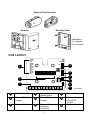 3
3
-
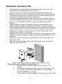 4
4
-
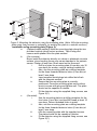 5
5
-
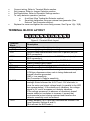 6
6
-
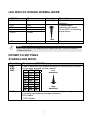 7
7
-
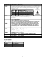 8
8
-
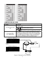 9
9
-
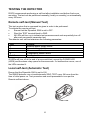 10
10
-
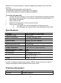 11
11
-
 12
12
-
 13
13
-
 14
14
-
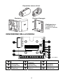 15
15
-
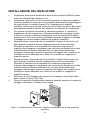 16
16
-
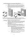 17
17
-
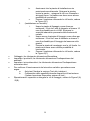 18
18
-
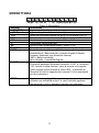 19
19
-
 20
20
-
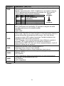 21
21
-
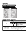 22
22
-
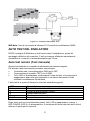 23
23
-
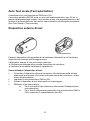 24
24
-
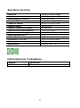 25
25
-
 26
26
-
 27
27
-
 28
28
-
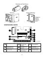 29
29
-
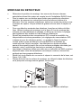 30
30
-
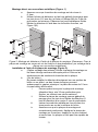 31
31
-
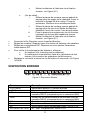 32
32
-
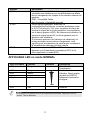 33
33
-
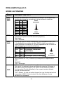 34
34
-
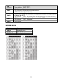 35
35
-
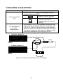 36
36
-
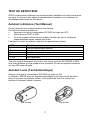 37
37
-
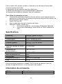 38
38
-
 39
39
-
 40
40
-
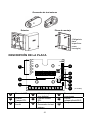 41
41
-
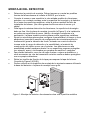 42
42
-
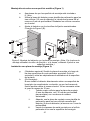 43
43
-
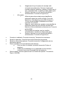 44
44
-
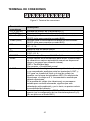 45
45
-
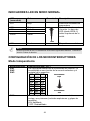 46
46
-
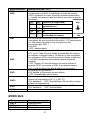 47
47
-
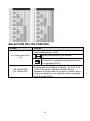 48
48
-
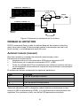 49
49
-
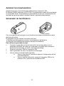 50
50
-
 51
51
-
 52
52
-
 53
53
-
 54
54
-
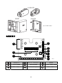 55
55
-
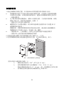 56
56
-
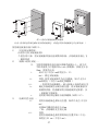 57
57
-
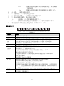 58
58
-
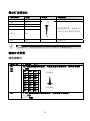 59
59
-
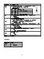 60
60
-
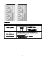 61
61
-
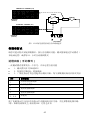 62
62
-
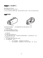 63
63
-
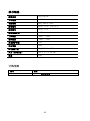 64
64
-
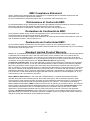 65
65
-
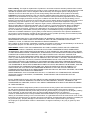 66
66
-
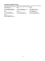 67
67
-
 68
68


en otros idiomas
- français: Risco RK66S Manuel utilisateur
- italiano: Risco RK66S Manuale utente
- English: Risco RK66S User manual
Artículos relacionados
-
Risco RK66S Manual de usuario
-
Risco Ind. LuNAR 200DTG3 Manual de usuario
-
-
Risco Industrial LuNAR RK200DTG3 Guía de instalación
-
-
 RISCO Group WatchOUT Guía de instalación
-
-
-

