
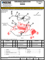
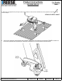
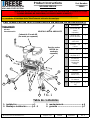
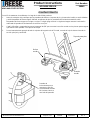
Installation Instructions
M5 HEAD Part Number:
30892
©2019 Horizon Global Sheet 1 of 7 30892N 05/29/19 Rev. A
WARNING:Under no circumstances do we recommend exceeding the towing vehicle manufacturers recommended vehicle towing capacity.
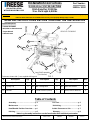
#Description Qty. #Description Qty. #Description Qty.
1Assembly –Head Unit 1 2 Handle 1 3 ½” Pull Pin 2
4Spring Clip 25a M8 Carriage Bolt 25b M8 Lock Washer 2
5c M8 Nut 26* Bolts & Washers 4
READ ALL INSTRUCTIONS BEFORE STARTING THE INSTALLATION
1. Assembly………..………………............p 2
2. Maintenance………………….………...p 3
3. Head/Handle Position Overview………p 4
4. Hitching…………….……...……………p 5
5. Pull Test………………..……..............p 5
6. Unhitching………..………………......p 6
7. Warranty………..….……..………….p 7
Table of Contents
*Note: Leg Assembly instructions can be found under their individual part number
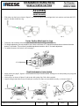
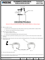
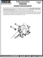
VEHICLE FORWARD
1
Legs Sold Separately
(GM shown)
2
3
4
5
5
4
3
Equipment Required:
Wrenches: M13
6*
FIG. 1
Fasteners shown with (*) are supplied with leg unit.
FOR INSTALLATION
WITH M5 MOUNTING LEGS
& CENTER SECTION
Center Section Sold
Separately
(20K shown)

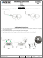
Assembly
x 2
x 2
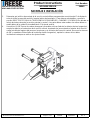
FIG. 2 FIG. 3
FIG. 6
FIG. 5
FIG. 4
Installation Instructions
HEAD Part Number:
30892
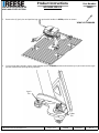
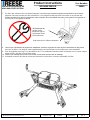
Handle Assembly
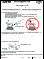
1. Slide tube over the bar as shown in figure 2, and securely tighten with carriage bolts, lock washers and nuts with M13 wrench.
Handle should be snug.
Head Attachment to Center Section
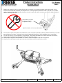
1. Apply grease per page 3, figures 7 & 8. Place head unit on top of center section as shown in figure 4, making sure to avoid putting
any body parts in pinch points
2. Insert pull pin as shown in figure 5, and secure with spring clips. Both sides required.
3. Inspect through sight holes on top of head pan to make sure clips are assembled correctly, as shown in figure 6
©2019 Horizon Global Sheet 2 of 7 30892N 05/29/19 Rev. A

Printed in Mexico
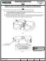
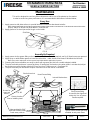
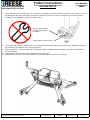
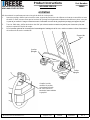
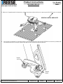
Typical Grease needle generally
available at auto parts stores
Installation Instructions
HEAD Part Number:
30892
Grease location
Prior to installing head
Head
1. Preventative lubrication should be applied to the following to keep the head functioning properly;
A. Apply grease to skid plate surface to provide lubricated surface for attachment to trailer.
Note: Plastic lube plates can be used to avoid messy grease. Plate must not exceed 3/16” in thickness to ensure hitch works
properly. REESE 5th Wheel Lube Plate #83001 is recommended.
B. Apply grease to 5th wheel jaw and/or kingpin on the trailer.
C. Apply grease via the grease fitting on the top of the unit. (Grease needle required, see fig. 8) Head comes pre-greased
D. Apply spray on white lithium grease to internal mechanisms -rotate handle a few times to distribute the lubricant.
Note: May need to wipe down unit to remove large debris before application of grease.
Before First Use and Periodic Required Maintenance
C
B
D
A
FIG. 7
FIG. 8
©2019 Horizon Global Sheet 3 of 7 30892N 05/29/19 Rev. A

Ready-to-Receive Position:
When will the head will be in this position?
-When delivered
-When hitch not in use
-When coupling to trailer
-After uncoupling from trailer
How to tell the head is in this position:
-Handle is pulled out fully until audible “CLICK” is heard and holes
DO NOT align for bail pin
-Handle is easily movable towards cab, and returns to
default position upon release
-Indicator shows RED
Locked Position:
When will the head will be in this position?
-When coupled to trailer
How to tell the head is in this position:
-Handle is in a position that holes align
for bail pin insertion.
-Indicator ONLY shows GREEN
Unhitching Position:
When will the head will be in this position?
-When unhitching the trailer
How to tell the head is in this position:
-Handle is in position shown*
-Indicator shows RED
*If there is tension between truck and trailer, the truck or trailer may shift when handle is pulled. In this case, handle will start to return to
ready-to-receive position, but trailer will still uncouple.
Functionality Overview
FIG. 9
FIG. 10
FIG. 11
Installation Instructions
HEAD Part Number:
30892
RED
RED
GREEN
©2019 Horizon Global Sheet 4 of 7 30892N 05/29/19 Rev. A
Bail pin holes
DO NOT Align
Bail pin holes
Do Align

Hitching Procedure
Before hitching to a trailer, make sure your 5th wheel height is correct.
Information on how to properly set the height of your 5th wheel hitch can be found in the Leg Installation Instructions.
Failure to follow these instructions may result in death or serious injury
1) Make sure truck and trailer is in position to couple
A. Truck tailgate is lowered if necessary
B. Blocks/Chocks are firmly against each trailer wheel to prevent any possible forward or rearward motion.
C. Pin box is at correct height for hitching (fig. 12 & 13).
D. Make sure head is in Ready-to-Receive position (pg. 4, fig. 9) by pulling the handle out fully
until an audible “CLICK” is heard
2) Back truck slowly into trailer so the trailer king pin and 5th wheel funnel align. When the indicator turns completely green, the
trailer king pin is securely held by the 5th wheel jaw (pg. 4, fig. 10).*
3) Perform Pull Test –
A. With trailer wheels still firmly blocked, trailer landing gears firmly on the ground supporting trailer weight, and trailer
brake on, make sure no one is between the truck and trailer.
B. Try to pull trailer slowly forward. If trailer is properly hitched, proceed to Step 4. If trailer is not properly hitched,
trailer will separate from hitch, and truck will move forward -repeat steps 1 thru 3.
4) Insert bail pin into lock hole, as shown in figure 14.
5) Connect electrical cable and breakaway switch cable between truck and trailer, raise tailgate if necessary.
6) Remove chocks/blocks and lift trailer jacks.
*Jaw may not close if under compression. If fully backed into trailer and not fully latched, pull truck slowly forward to remove load on jaw. Handle
will fully latch.
FIG. 12 FIG. 13
Bottom of Pin Box to be aligned
with top of Skid Plate ramp +/-1
inch
Bail pin shown inserted & locked
FIG. 14
CONTACT ZONE
+/-1in. from top of
skid plate ramp
Installation Instructions
HEAD Part Number:
30892
Indicator shows
Green
©2019 Horizon Global Sheet 5 of 7 30892N 05/29/19 Rev. A

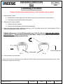
Unhitching Procedure
Failure to follow these instructions may result in death or serious injury
1) Make sure trailer is secure
A. Blocks/Chocks are firmly against each trailer wheel to prevent any possible forward or rearward motion.
B. Trailer jacks are lowered and are firmly on the ground
2) Make sure truck is ready to unhitch:
A. Tailgate is lowered if necessary
B. Electrical cable and breakaway switch cable are disconnected.
3) Remove bail pin and move handle to unhitching position (pg. 4, fig. 11) by pulling out fully (fig. 15) until an audible “CLICK” is
heard then rotating handle towards cab (fig. 16).*
4) Drive truck slowly away from trailer
*If there is tension between truck and trailer, the truck or trailer may shift when handle is pulled. In this case, handle will start to return to ready-to-
receive position, but trailer will still uncouple.
FIG. 15 FIG. 16
Installation Instructions
HEAD Part Number:
30892
©2019 Horizon Global Sheet 6 of 7 30892N 05/29/19 Rev. A
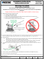
Trailer pin box VEHICLE FORWARD
If handle will not move to the unhitching position (pg. 4, fig. 11) with ease, STOP, DO NOT FORCE
THE HANDLE!!! The jaw may not open if under tension. Slowly reverse truck to remove load on
the jaw before attempting to unhitch trailer.

Installation Instructions
Head
NOTES:
Horizon Global
47912 Halyard Drive Suite 100
Plymouth, MI 48170
LIMITED LIFETIME WARRANTY
1. Limited Lifetime Warranty (“Warranty”). Horizon Global (“We” or “Us”) warrants to the original consumer purchaser only
(“You”) that the product will be free from material defects in both material and workmanship for a period of lifetime of
ownership, ordinary wear and tear excepted; provided that installation and use of the product is in accordance with product
instructions. There are no other warranties, express or implied, including the warranty of merchantability or fitness for a
particular purpose. This warranty is not transferable.
2. Limitations on the Warranty. This Warranty does not cover: (a) normal wear and tear; (b) damage through abuse, neglect,
misuse, or as a result of any accident or in any other manner; (c) damage from misapplication, overloading, or improper
installation; (d) improper maintenance and repair; and (e) product alteration in any manner by anyone other than Us, with the
sole exception of alterations made pursuant to product instructions and in a workmanlike manner.
3. Obligations of Purchaser. To make a Warranty claim, contact Us at 47912 Halyard Drive Suite 100, Plymouth, MI, 48170,
1-800-632-3290, identify the product by model number, and follow the claim instructions that will be provided. Any returned
product that is replaced by Us becomes our property. You will be responsible for return shipping costs. Please retain your
purchase receipt to verify date of purchase and that You are the original consumer purchaser. The product and the purchase
receipt must be provided to Us in order to process Your warranty claim.
4. Remedy Limits. Product replacement is Your sole remedy under this Warranty. We shall not be liable for service or labor
charges incurred in removing or replacing a product or any incidental or consequential damages of any kind.
5. Assumption of Risk. You acknowledge and agree that any use of the product for any purpose other than the specified use(s)
stated in the product instructions is at Your own risk.
6. Governing Law. This Warranty gives You specific legal rights, and You also may have other rights which vary from state
to state. This Warranty is governed by the laws of the State of Michigan, without regard to rules pertaining to conflicts of
law. The state courts located in Oakland County, Michigan shall have exclusive jurisdiction for any disputes relating to this
Warranty.
Part Number Purchased:
Place of Purchase:
Date of Purchase:
Part Manufactured Date (located on driver-side sticker):
©2019 Horizon Global Sheet 7 of 7 30892N 05/29/19 Rev. A

fInstallation Instructions
M5 HEAD & CENTER SECTION
Hitch Rated for 32,000 lbs,
Max. Pin Weight 6,400 lbs
Part Number:
30892 & 30932
©2020 Horizon Global America Inc. Sheet 1 of 8 30932N 04/20/20 Rev. A
# Description Qty. # Description Qty. # Description Qty.
1 Assembly –Head Unit 1 2 Handle 1 3 ½” Pull Pin 2
4 Spring Clip 2 5a M8 Carriage Bolt 2 5b M8 Lock Washer 2
5c M8 Nut 2 6 Center Section (30932) 1 7* Bolts, Nuts & Washers 4
READ ALL INSTRUCTIONS BEFORE STARTING THE INSTALLATION
Assembly………..………………..........p 2
Maintenance………………….………..p 3
Head/Handle Position Overview……p 4
Hitching…………….……...……………p 5
Pull Test………………..……..............p 5
Unhitching………..………………......p 6
Added Clearance to Cab…....………p 7
Warranty………..….……..….……….p 8
Table of Contents
*Note: Leg Assembly instructions can be found under their individual part number
VEHICLE FORWARD
1
Legs Sold Separately
(Ford shown)
2
3
4
5
5
4
3
Equipment Required:
•Fastener kit 30892F
•M13, M24 socket and wrench
•Torque Wrench
•Lithium Grease
6
7*
FIG. 1
Fasteners shown with (*) are supplied with leg unit.
FOR INSTALLATION
WITH M5 MOUNTING LEGS
WARNING: Under no circumstances do we recommend exceeding the towing vehicle manufacturers recommended vehicle towing capacity.
Failure to follow instructions for installation and use may cause property damage, injury or death.
7*
7*

Handle Assembly
1. Slide tube over the bar as shown in figure 2, and securely tighten with carriage bolts, lock washers and nuts with M13
wrench. Handle should be snug.
Center Section Attachment to Legs
1. Fasteners and assembly instructions are included with the set of legs, sold separately.
2. For height adjustment, the unit should be set to have a minimum of 6” clearance between the truck bed rail and the
bottom of the trailer. This unit has 3 possible attachment locations, with 4” of overall adjustment.
3. For added clearance to the truck cab, see page 7.
Head Attachment to Center Section
1. Apply grease per page 3, figure 9. Place head unit on top of center section, making sure to avoid putting any body parts
in pinch points
2. Insert pull pin as shown in figure 6, and secure with spring clips. Both sides required.
3. Inspect through sight holes on top of head pan to make sure clips are assembled correctly, as shown in figure 7
Assembly
x 2
x 2
FIG. 2 FIG. 3
FIG. 7FIG. 6FIG. 5
Installation Instructions
HEAD & CENTER SECTION Part Number:
30892 & 30932
4” of Adjustment
FIG. 4
©2020 Horizon Global America Inc. Sheet 2 of 8 30932N 4/20/20 Rev. A
Pinch areas
Sight Holes

Printed in Mexico
Typical Grease needle generally
available at auto parts stores
Installation Instructions
HEAD & CENTER SECTION Part Number:
30892 & 30932
Grease location
Prior to installing head
Hole provided for 5/16”
eye bolt to attach trailer
break-away cable to.
Pivot Grease fitting.
Accessible thru logo/load
rating slot. Use of grease
needle required.
Maintenance
FIG. 9A
©2020 Horizon Global America Inc. Sheet 3 of 8 30932N 4/20/20 Rev. A
FIG. 9B
Pivot bolt and nut
Access for
open end
wrench
This unit is designed to need very little maintenance and be one of the quietest on the market.
In order to ensure long term performance, it is recommended to lubricate as indicated below;
Every Use
1. Apply grease to skid plate surface, to provide lubricated surface for attachment to trailer.
Note: Plastic lube plates can be used to avoid messy grease. Plate must not exceed 3/16” in thickness to ensure hitch works
properly. REESE 5th Wheel Lube Plate #83001 is recommended.
2. Apply grease to 5th wheel jaw and/or kingpin on the trailer.
Jaw
Skid Plate
FIG. 8
Annually/As Required
1. Apply grease via the grease fitting on the top of the unit. (Grease needle required, see fig. 9) Head comes pre-greased
2. Apply spray on white lithium grease to internal mechanisms - rotate handle a few times to distribute the lubricant.
Note: May need to wipe down unit to remove large debris before application of grease.
3. Greasing the pivot assemblies can easily be done with a grease gun that has a needle adapter installed.
4. The pivot assembly resistance is preset at factory. If head pivots and makes noise when trailer is not attached, adjust
the resistance more by tighten pivot bolt 1/2 turn at a time (2 full turns max.). See figure 9B.
5. The pivot assembly can be rebuilt if require. Instructions to do this will be in rebuild kit.
Head Grease fitting
Internal Mechanisms

Ready-to-Receive Position:
When will the head will be in this position?
- When delivered
- When hitch not in use
- When coupling to trailer
- After uncoupling from trailer
How to tell the head is in this position:
- Handle is pulled out so holes do not align for bail pin
- Handle is easily movable towards cab, and returns to
default position upon release
- Indicator shows RED
Locked Position:
When will the head will be in this position?
- When coupled to trailer
How to tell the head is in this position:
- Handle is in a position that holes align
for bail pin insertion.
- Indicator ONLY shows GREEN
Unhitching Position:
When will the head will be in this position?
- When unhitching the trailer
How to tell the head is in this position:
- Handle is in position shown*
- Indicator shows RED
*If there is tension between truck and trailer, the truck or trailer may shift when handle is pulled. In this case, handle will start to return to
ready-to-receive position, but trailer will still uncouple.
Functionality Overview
FIG. 10
FIG. 11
FIG. 12
Installation Instructions
HEAD & CENTER SECTION Part Number:
30892 & 30932
RED
RED
GREEN
©2020 Horizon Global America Inc. Sheet 4 of 8 30932N 4/20/20 Rev. A
Bail pin hole

Hitching Procedure
Before hitching to a trailer, make sure your 5th wheel height is correct.
Information on how to properly set the height of your 5th wheel hitch can be found in the Leg Installation
Instructions.
Failure to follow these instructions may result in death or serious injury
1) Make sure truck and trailer is in position to couple
A. 5th wheel is correctly secured to truck
B. Truck tailgate is lowered if necessary
C. Blocks/Chocks are firmly against each trailer wheel to prevent any possible forward or rearward motion.
D. Pin box is at correct height for hitching (fig. 13 & 14).
E. Make sure head is in Ready-to-Receive position (pg. 4, fig.10)
2) Back truck slowly into trailer so the trailer king pin and 5th wheel funnel align. Hitch will latch automatically when truck is
backed completely into trailer king pin. When this occurs, the indicator will be 100% green (pg. 4, fig. 11).*
3) Perform Pull Test –
A. With trailer wheels still firmly blocked, trailer landing gears firmly on the ground supporting trailer weight, and
trailer brake on, make sure no one is between the truck and trailer.
B. Try to pull trailer slowly forward. If trailer is properly hitched, proceed to Step 4. If trailer is not properly
hitched, trailer will separate from hitch, and truck will move forward - repeat steps 1 thru 3.
4) Insert bail pin into lock hole, as shown in figure 15, or lock for added security. Possible lock dimensions shown on
page 6.
5) Connect electrical cable and breakaway switch cable between truck and trailer, raise tailgate if necessary.
6) Remove chocks/blocks and lift trailer jacks.
*Jaw may not close if under compression. If fully backed into trailer and not fully latched, pull truck slowly forward to remove load on jaw.
Handle will fully latch.
FIG. 13 FIG. 14
Bottom of Pin Box to be aligned
with top of Skid Plate ramp +/-
1 inch
Bail pin shown inserted & locked
FIG. 15
CONTACT ZONE
+/- 1in. from top of
skid plate ramp
Installation Instructions
HEAD & CENTER SECTION Part Number:
30892 & 30932
Indicator shows
Green
©2020 Horizon Global America Inc. Sheet 5 of 8 30932N 4/20/20 Rev. A

Unhitching Procedure
Failure to follow these instructions may result in death or serious injury
1) Make sure trailer is secure
A. Blocks/Chocks are firmly against each trailer wheel to prevent any possible forward or rearward motion.
B. Trailer jacks are lowered and are firmly on the ground
2) Make sure truck is ready to unhitch:
A. Tailgate is lowered as necessary
B. Electrical cable and breakaway switch cable are disconnected.
3) As truck and trailer may shift when unhitching, ensure no person or vehicle is in the vicinity of truck or trailer when
unhitching
4) Remove bail pin from locking hole, and move handle to unhitching position (fig. 17) by pulling out and rotating towards
handle towards cab.*
5) Drive truck slowly away from trailer
*If there is tension between truck and trailer, the truck or trailer may shift when handle is pulled. In this case, handle will start to return to
ready-to-receive position, but trailer will still uncouple.
FIG. 16 FIG. 17
Installation Instructions
HEAD & CENTER SECTION Part Number:
30892 & 30932
©2020 Horizon Global America Inc. Sheet 6 of 8 30932N 4/20/20 Rev. A
Trailer pin box
1-1/2”
or greater
3/4” or greater
Ø 5/16” or less

Printed in Mexico
TO INCREASE THE GAP BETWEEN TRAILER AND TRUCK CAB by 1-1/2”.
Logo/Rating cover
Plastic retainers
Grease points
Grease points
Head springs
View holes to
help spring clip
installation
Installation Instructions
HEAD & CENTER SECTION Part Number:
30892 & 30932
FIG. 18
©2020 Horizon Global America Inc. Sheet 7 of 8 30932N 4/20/20 Rev. A
Head spring
assembly
Pinch
points
Pinch
points
Shown in factory location with offset towards cab of truck
The center section has an option to increase the gap between the trailer front and the truck cab by 1-1/2” by rotating the center section
180 degrees.
Location of king pin should be ahead of truck rear axle and have proper truck cab clearance
1. Remove the head by pulling the spring clips off the head retainer pins. Then pull the head retainer pin out of the head.
Hint; A slight push down on the head will help this. Caution, avoid getting fingers pinched.
2. Lift the head off and set aside.
3. Remove the bolts holding the legs on the center section and rotate the center section (all vehicles), OR disconnect the feet from
the bed and rotate the center section and leg assembly (not possible with RAM vehicles).
4. Re connect the center section or the center section and leg assembly per the installation instructions of that portion.
5. Remove the logo/rating cover by gently prying the two lower plastic retainers with the cover away from the center section. Avoid
scratching the paint by using plastic auto trim tools. The top will pivot and pull away once the cover rotates up enough.
6. Re-install on the other side (truck rear) by reversing the above process.
7. Remove the head springs by removing the 1/4” bolt (7/16” socket) and flip them from right to left. When installed properly, the
springs should be pointing up towards the truck cab and tighten to 7-8 ft-lbs. Springs will flex freely.
8. Re apply grease to the head and center section interface and re-install the head per instructions.
Caution; place hands or fingers on either side of the pivot interface to prevent pinching.
9. Re-install head retainer pins and clips per head instructions.
*30894 27k Center section shown

Product Instructions:
Head & Center Section
NOTES:
Horizon Global America, Inc
47912 Halyard Drive Suite 100
Plymouth, MI 48170
LIMITED LIFETIME WARRANTY
1. Limited Lifetime Warranty (“Warranty”). Horizon Global (“We” or “Us”) warrants to the original consumer purchaser
only (“You”) that the product will be free from material defects in both material and workmanship for a period of
lifetime of ownership, ordinary wear and tear excepted; provided that installation and use of the product is in
accordance with product instructions. There are no other warranties, express or implied, including the warranty of
merchantability or fitness for a
particular purpose. This warranty is not transferable.
2. Limitations on the Warranty. This Warranty does not cover: (a) normal wear and tear; (b) damage through abuse,
neglect, misuse, or as a result of any accident or in any other manner; (c) damage from misapplication, overloading,
or improper installation; (d) improper maintenance and repair; and (e) product alteration in any manner by anyone
other than Us, with the sole exception of alterations made pursuant to product instructions and in a workmanlike
manner.
3. Obligations of Purchaser. To make a Warranty claim, contact Us at 47912 Halyard Drive Suite 100, Plymouth, MI,
48170, 1-800-632-3290, identify the product by model number, and follow the claim instructions that will be provided.
Any returned product that is replaced by Us becomes our property. You will be responsible for return shipping costs.
Please retain your purchase receipt to verify date of purchase and that You are the original consumer purchaser.
The product and the purchase receipt must be provided to Us in order to process Your warranty claim.
4. Remedy Limits. Product replacement is Your sole remedy under this Warranty. We shall not be liable for service
or labor charges incurred in removing or replacing a product or any incidental or consequential damages of any kind.
5. Assumption of Risk. You acknowledge and agree that any use of the product for any purpose other than the
specified use(s) stated in the product instructions is at Your own risk.
6. Governing Law. This Warranty gives You specific legal rights, and You also may have other rights which vary from
state to state. This Warranty is governed by the laws of the State of Michigan, without regard to rules pertaining to
conflicts of law. The state courts located in Oakland County, Michigan shall have exclusive jurisdiction for any
disputes relating to this Warranty.
Part Number Purchased:
Place of Purchase:
Date of Purchase:
Part Manufactured Date (located on driver-side sticker):
©2020 Horizon Global America Inc. Page 8 of 8 30932N 04/20/20 Rev. A

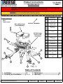
Product Instructions
M5 RAM 32K LEG
Part Number:
30949
FOR INSTALLATION WITH M5
HEAD AND CENTER SECTION
© 2021 Horizon Global America Inc. 30949N 04/20/2021 Rev. A
Page 1 of 21
10
1. Installation ---------------------------- p 1
2. Assembly and Installation ------- p 2 - 5 3. Maintenance ------------------------------- p 6
4. Warranty ------------------------------------ p 7
CAUTION: Under no circumstances do we recommend exceeding the towing vehicle
manufacturers recommended vehicle towing capacity.
READ ALL INSTRUCTIONS BEFORE STARTING THE INSTALLATION OR USE
Table of Contents
VEHICLE FORWARD
5
1
M5 5th Wheel Head
(Sold Separately)
FIG. 1
4
M5 32K Center
Section (Sold
Separately)
6
2
8
7
9
WARNING: FAILURE TO FOLLOW INSTALLATION AND HITCH-UP INSTRUCTIONS MAY
CAUSE PROPERTY LOSS, SERIOUS INJURY, OR DEATH!
Equipment Required:
Wrenches: 15/16”
Pliers
Torque wrench
# Description QTY.
1 M5 Ram Leg
(Left Hand) 1
2 M5 Ram Leg
(Right Hand) 1
3 Bolt-5/8-11 x
4.25” GR8 4
4 Washer – 5/8”
Conical 4
5 Nut – 5/8”-11 4
6 Handle, T-Pin
Locking 4
7 Lynch Pin,
Handle Lock 4
8 Castle Nut 4
9 Cotter Pin 8
10 Front T-
Pin Ram
Leg 2
11 Rear T-Pin Ram
Leg 2
12 T-Bushing Ram
Leg 4
3
11
12
11

Product Instructions
M5 RAM 32K LEG
Part Number:
30949
FOR INSTALLATION WITH M5
HEAD AND CENTER SECTION
© 2021 Horizon Global America Inc. 30949N 04/20/2021 Rev. A
Page 2 of 21
1. The M5 RAM Legs comes ready to install. NOTE: There is a Left and Right hand leg!
2. Each leg should have one large and one small T-Pin/T-Bushing as shown above. With the small T-
Pin/T-Bushing being the front mounting location and the large T-Pin/T-Bushing being for the rear.
Be sure to place the legs correctly onto the center box, with the small T-Pin/T-Bushing in the front
on both sides!
11
11
10
ASSEMBLY AND INSTALLATION
SMALL LARGE
9

Product Instructions
M5 RAM 32K LEG
Part Number:
30949
FOR INSTALLATION WITH M5
HEAD AND CENTER SECTION
© 2021 Horizon Global America Inc. 30949N 04/20/2021 Rev. A
Page 3 of 21
3. Determine which center section mounting holes to use to ensure a minimum of 6” clearance between the truck
bed rail and the bottom of the trailer. ( For more detail, please refer to the GUIDELINES FOR MATCHING
HITCH, TRUCK, AND TRAILER section located in the head and center section instruction sheet.) Legs should
be attached at same height on both sides of unit. This unit has 4” of vertical adjustment.
4. Using the (4) 5/8” Hex Head Bolts and conical washers (teeth side toward hitch), attach the legs to the center
section structure, inserting the bolts from the outside of the center section through the bolt hole in the legs and
into the inside of the center section. Thread on the 5/8” nuts and conical washers (teeth side toward hitch),
finger tighten fasteners initially until final adjustments are made.
ASSEMBLY AND INSTALLATION

Product Instructions
M5 RAM 32K LEG
Part Number:
30949
FOR INSTALLATION WITH M5
HEAD AND CENTER SECTION
© 2021 Horizon Global America Inc. 30949N 04/20/2021 Rev. A
Page 4 of 21
5. Remove the (4) lynch pins and position legs over pucks with handles in OPEN position as shown.
6. Once unit has been placed in pucks, rotate handles back to CLOSED position and insert the lynch pins back into the leg to
prevent handles from opening during operation.
VEHICLE FORWARD
Lynch
Pin
Cotter
Pin

Product Instructions
M5 RAM 32K LEG
Part Number:
30949
FOR INSTALLATION WITH M5
HEAD AND CENTER SECTION
© 2021 Horizon Global America Inc. 30949N 04/20/2021 Rev. A
Page 5 of 21
7. Due to variations in truck underbeds, it is normal for some handles to be loose and other handles to be too tight to lock. If a
handle appears too loose and rattles or cannot be closed fully, remove the cotter pin and adjust castle nut by hand to a
position where handle does not rattle or is able to close.
8. Once handle adjustment is satisfactory, re-insert cotter pin and bend end with pliers to hold in place. Additional cotter pins
are provided in the hardware kit for your convenience.
9. With Ram Leg T-Pin handles locked and T-Pins securely held in underbed structure, tighten each 5/8” hex-head bolt to
210 ft-lb of torque.
10. Verify that hitch is tight to truck bed by lifting each side of the hitch.
11. Assemble head to center section per instructions included with M5 Center Section and Head.
Finger tighten castle nut only!
(Do not install cotter pin
until final adjustments
are made)

Product Instructions
M5 RAM 32K LEG
Part Number:
30949
FOR INSTALLATION WITH M5
HEAD AND CENTER SECTION
© 2021 Horizon Global America Inc. 30949N 04/20/2021 Rev. A
Page 6 of 21
In order to maintain performance over the life of the product:
1. Before any trip, verify that cotter pins, foot bracket and castle nut are undamaged and securely locked. Additionally ensure
that the lynch pins are also securely locked in place, with little to no vertical play. The image below shows the proper
orientation of the lynch pin in relation to the foot.
2. Every 1,000 miles, check the 5/8” hex bolts that connect center section to legs to insure that they are still torqued to 210 ft-
lb of torque.
3. For general maintenance of the entire 5th wheel hitch assembly, please refer to the M5 head and center section instruction
sheet.
MAINTENANCE
Lynch pin shown in
properly closed position.
DO NOT reverse loop to
other side of pin!
Lynch
Pin
Cotter
Pin
Foot Bracket

Product Instructions
M5 RAM 32K LEG
Part Number:
30949
FOR INSTALLATION WITH M5
HEAD AND CENTER SECTION
© 2021 Horizon Global America Inc. 30949N 04/20/2021 Rev. A
Page 7 of 21
LIMITED LIFETIME WARRANTY
Horizon Global Corporation. (“We” or “Us”) warrants to the original consumer purchaser only (“You”) that the product
will be free from material defects in both material and workmanship, ordinary wear and tear expected; provided that
installation and use of the product is in accordance with product instructions. There are no other warranties, express
or implied, including the warranty of merchantability or fitness for a particular purpose. This warranty is not
transferable.
This warranty does not cover: (a) normal wear and tear; (b) damage through abuse, neglect, misuse, or as a result of
any accident or in any other manner; (c) damage from misapplication, overloading, or improper installation; (d)
improper maintenance and repair; and (e) product alteration in any manner by anyone other than Us, with the sole
exception of alterations made pursuant to product instructions and in a workmanlike manner.
To make a Warranty claim, contact Us, at our principal address of 47912 Halyard Dr. Suite 100, Plymouth, MI 48170,
1-800-632-3290, identify the product by model number, and follow the claim instructions that will be provided. Any
returned product that is replaced by Us becomes our property. You will be responsible for return shipping costs.
Please retain your purchase receipt to verify date of purchase and that You are the original consumer purchaser. The
product and the purchase receipt must be provided to Us in order to process Your Warranty claim.
Product replacement is Your sole remedy under this Warranty. We shall not be liable for service or labor charges
incurred in removing or replacing a product or any incidental or consequential damages of any kind.
You acknowledge and agree that any use of the product for any purpose other than the specified use(s) stated in the
product instructions is at Your own risk.
This Warranty gives you specific legal rights, and You may also have other rights which vary from state to state. This
Warranty is governed by the laws of the State of Michigan, without regard to rules pertaining to conflicts of law. The
state courts located in Oakland county, Michigan shall have exclusive jurisdiction for any disputes relating to this
warranty.
Horizon Global
47912 Halyard Dr. Suite 100
Plymouth, MI 48170
For the most up to date product
instructions, installation and use
information please scan the QR
code or call

Product Instructions
M5 RAM 32K LEG
Part Number:
30949
FOR INSTALLATION WITH M5
HEAD AND CENTER SECTION
© 2021 Horizon Global America Inc. 30949N 04/20/2021 Rev. A
Page 8 of 21
10
1. Installation ---------------------------- p 1
2. Assemblée et Installation ------- p 2 - 5 3. entretien ------------------------------- p 6
4. garantie ------------------------------------ p 7
ATTENTION : En aucun cas, nous ne recommandons de dépasser la capacité de
remorquage recommandée par les constructeurs de véhicules.
LIRE TOUTES LES INSTRUCTIONS AVANT DE COMMENCER L’INSTALLATION
OU L’UTILISATION
Tableau des matières
VÉHICULE VERS L’AVANT
5
1
M5 5ème Tête de roue
(Vendu séparément)
FIG. 1
4
M5 32K Center
Section (Vendu
séparément)
6
2
8
7
9
AVERTISSEMENT : LE NON-RESPECT DES INSTRUCTIONS D’INSTALLATION ET
D’ATTELAGE PEUT CAUSER UNE PERTE DE BIENS, DES BLESSURES GRAVES OU LA MORT!
Équipement requis :
Clés: 15/16
pinces
clé dynamométrique
# description QTY.
1 Jambe de bélier
M5 (main
gauche)
1
2 M5 Ram Leg
(Main droite) 1
3 Bolt-5/8-11 x
4.25 » GR8 4
4 Laveuse –5/8 »
Conique 4
5 Écrou –5/8 »-11 4
6 Poignée,
verrouillage de t-
pin
4
7 Goupille
lynchée, serrure
de poignée
4
8 Écrou de
château
goupille
4
9 Écrou de
château
goupille
8
10 Jambe de bélier
avant de T-Pin 2
11 Jambe de bélier
arrière de T-Pin 2
12 Jambe de bélier
de T-Bushing 4
3
11
12
11

Product Instructions
M5 RAM 32K LEG
Part Number:
30949
FOR INSTALLATION WITH M5
HEAD AND CENTER SECTION
© 2021 Horizon Global America Inc. 30949N 04/20/2021 Rev. A
Page 9 of 21
1. Le M5 RAM Legs est prêt à installer. REMARQUE : Il y a une jambe gauche et droite!
2. Chaque jambe doit avoir un grand et un petit T-Pin/T-Bushing comme indiqué ci-dessus. Avec le
petit T-Pin /T-Bushing étant l’emplacement de montage avant et le grand T-Pin / T-Bushing étant
pour l’arrière. Assurez-vous de placer les jambes correctement sur la boîte centrale, avec le petit T-
Pin / T-Bushing à l’avant des deux côtés!
3.
11
11
10
ASSEMBLAGE ET INSTALLATION
petit grand
9

Product Instructions
M5 RAM 32K LEG
Part Number:
30949
FOR INSTALLATION WITH M5
HEAD AND CENTER SECTION
© 2021 Horizon Global America Inc. 30949N 04/20/2021 Rev. A
Page 10 of 21
3. Déterminez les trous de montage de la section centrale à utiliser pour assurer un dégagement d’au moins 6
pieds entre le rail de lit du camion et le fond de la remorque. ( Pour plus de détails, veuillez consulter la section
LIGNES DIRECTRICES POUR L’ATTELAGE CORRESPONDANT, LE CAMION ET LA REMORQUE situé
dans la fiche d’instructions de la section principale et centrale.) Les jambes doivent être fixées à la même
hauteur des deux côtés de l’unité. Cette unité a 4 » d’ajustement vertical.
4. À l’aide des boulons hex (4) 5/8 » et des rondelles coniques (côté dents vers l’attelage), fixez les jambes à la
structure de la section centrale, en insérant les boulons de l’extérieur de la section centrale par le trou de
boulon dans les jambes et à l’intérieur de la section centrale. Enfiler sur les écrous et les rondelles coniques de
5/8 » (côté dents vers l’attelage), serrer les attaches au début jusqu’à ce que les ajustements finaux soient
effectués.
ASSEMBLAGE ET INSTALLATION

Product Instructions
M5 RAM 32K LEG
Part Number:
30949
FOR INSTALLATION WITH M5
HEAD AND CENTER SECTION
© 2021 Horizon Global America Inc. 30949N 04/20/2021 Rev. A
Page 11 of 21
5. Retirez les (4) goupilles de lynchage et placez les jambes au-dessus des rondelles avec des poignées en position OPEN
comme indiqué.
6. Une fois que l’appareil a été placé dans des rondelles, faites pivoter les poignées vers la position FERMÉE et insérez les
broches de lynchage dans la jambe pour empêcher les poignées de s’ouvrir pendant le fonctionnement.
VÉHICULE VERS L’AVANT
lyncher
épingler
Cotter
épingler

Product Instructions
M5 RAM 32K LEG
Part Number:
30949
FOR INSTALLATION WITH M5
HEAD AND CENTER SECTION
© 2021 Horizon Global America Inc. 30949N 04/20/2021 Rev. A
Page 12 of 21
7. En raison des variations des sous-lits des camions, il est normal que certaines poignées soient lâches et que d’autres
poignées soient trop serrées pour être verrouillées. Si une poignée semble trop lâche et hochets ou ne peut pas être
fermée complètement, retirez la goupille de cotter et ajustez l’écrou de château à la main à une position où la poignée ne
hochets pas ou est capable de fermer.
8. Une fois que l’ajustement de poignée est satisfaisant, réinsérez la goupille de cotter et pliez l’extrémité avec des pinces
pour tenir en place. Des broches cotter supplémentaires sont fournies dans le kit matériel pour votre commodité.
9. Avec les poignées Ram Leg T-Pin verrouillées et les T-Pins solidement maintenus dans la structure sous-lit, serrez chaque
boulon de 5/8 » hex-tête à 210 pi-lb de couple.
10. Vérifiez que l’attelage est serré au lit du camion en soulevant chaque côté de l’attelage.
11. Assembler la section de la tête au centre par instructions incluses avec la section centrale M5 et la tête.
Doigt serrer écrou château seulement!
(N’installez pas de
goupille cotter
jusqu’à ce que les
ajustements finaux
soient effectués)

Product Instructions
M5 RAM 32K LEG
Part Number:
30949
FOR INSTALLATION WITH M5
HEAD AND CENTER SECTION
© 2021 Horizon Global America Inc. 30949N 04/20/2021 Rev. A
Page 13 of 21
Afin de maintenir les performances tout au long de la durée de vie du produit:
1. Avant tout voyage, vérifiez que les broches cotter, support de pied et écrou de château sont intacts et verrouillés en toute
sécurité. En outre, assurez-vous que les broches de lynchage sont également solidement verrouillées en place, avec peu
ou pas de jeu vertical. L’image ci-dessous montre l’orientation correcte de la goupille de lynchage par rapport au pied.
2. Tous les 1000 miles, vérifiez les boulons hex 5/8 " qui relient la section centrale aux jambes pour s’assurer qu’ils sont
toujours coupled à 210 pi-lb de couple.
3. Pour l’entretien général de l’ensemble de l’assemblage de l’attelage de la 5e roue, veuillez consulter la fiche d’instructions
de la tête et de la section centrale M5.
entretien
Goupille lynchée
montrée en position
correctement fermée.
NE PAS inverser la
boucle de l’autre côté de
la goupille!
lyncher
épingler
Cotter
épingler
Support de
pied

Product Instructions
M5 RAM 32K LEG
Part Number:
30949
FOR INSTALLATION WITH M5
HEAD AND CENTER SECTION
© 2021 Horizon Global America Inc. 30949N 04/20/2021 Rev. A
Page 14 of 21
GARANTIE À VIE LIMITÉE
Horizon Global Corporation. (« Nous » ou « Nous ») justifie à l’acheteur consommateur d’origine seulement
(« Vous ») que le produit sera exempt de défauts matériels à la fois dans le matériel et l’exécution, l’usure ordinaire
prévue; à condition que l’installation et l’utilisation du produit soit conforme aux instructions du produit. Il n’y a pas
d’autres garanties, expresses ou implicites, y compris la garantie de marchandité ou d’aptitude à une fin particulière.
Cette garantie n’est pas transférable.
Cette garantie ne couvre pas : a) l’usure normale; b) les dommages causés par la violence, la négligence, l’abus ou à
la suite d’un accident ou d’une autre manière; c) dommages causés par une mauvaise application, une surcharge ou
une installation inappropriée; d) entretien et réparation inadéquats; e) la modification du produit de quelque manière
que ce soit par quelqu’un d’autre que nous, à l’exception des modifications apportées conformément aux instructions
du produit et d’une manière professionnelle.
Pour faire une demande de garantie, communiquez avec nous, à notre adresse principale du 47912 Halyard Dr. Suite
100, Plymouth, MI 48170, 1-800-632-3290, identifiez le produit par numéro de modèle et suivez les instructions de
réclamation qui seront fournies. Tout produit retourné qui est remplacé par Nous devient notre propriété. Vous serez
responsable des frais d’expédition de retour. Veuillez conserver votre reçu d’achat pour vérifier la date d’achat et que
vous êtes l’acheteur consommateur d’origine. Le produit et le reçu d’achat doivent nous être fournis afin de traiter
votre demande de garantie.
Le remplacement du produit est votre seul recours en vertu de cette garantie. Nous ne serons pas responsables des
frais de service ou de main-d’œuvre engagés dans la suppression ou le remplacement d’un produit ou de tout
dommage accessoire ou conséquent de quelque nature que ce soit.
Vous reconnaissez et acceptez que toute utilisation du produit à d’autres fins que l’utilisation spécifiée(s) indiquée
dans les instructions du produit est à vos risques et périls.
Cette garantie vous donne des droits juridiques spécifiques, et vous pouvez également avoir d’autres droits qui
varient d’un État à l’autre. Cette garantie est régie par les lois de l’État du Michigan, sans égard aux règles relatives
aux conflits de droit. Les tribunaux d’État situés dans le comté d’Oakland, michigan doivent avoir compétence
exclusive pour tous les litiges relatifs à cette garantie.
Horizon Global
47912 Halyard Dr. Suite 100
Plymouth, MI 48170
Pour les instructions de produit
les plus à jour, l’installation et
l’utilisation des informations s’il
vous plaît numériser le code QR
ou appeler

Product Instructions
M5 RAM 32K LEG
Part Number:
30949
FOR INSTALLATION WITH M5
HEAD AND CENTER SECTION
© 2021 Horizon Global America Inc. 30949N 04/20/2021 Rev. A
Page 15 of 21
10
1. instalación ---------------------- p 1
2. Montaje e instalación ------- p 2 - 5 3. mantenimiento -------------------------- p 6
4. garantía ------------------------------------ p 7
PRECAUCIÓN: Bajo ninguna circunstancia recomendamos exceder la capacidad
recomendada de remolque de los fabricantes de vehículos de remolque.
LEA TODAS LAS INSTRUCCIONES ANTES DE INICIAR LA INSTALACIÓN O
Tabla de contenidos
VEHÍCULO HACIA ADELANTE
5
1
Cabezal de 5ª rueda M5
(Se vende por separado)
FIG. 1
4
Sección centro
M5 32K (se
vende por
separado)
6
2
8
7
9
ADVERTENCIA: NO SEGUIR LAS INSTRUCCIONES DE INSTALACIÓN Y ENGANCHE PUEDE
CAUSAR PÉRDIDA DE PROPIEDAD, LESIONES GRAVES O MUERTE!
Equipo requerido:
Llaves: 15/16"
alicates
Llave de torsión
# descripción QTY.
1 Pierna ram M5
(mano
izquierda)
1
2 M5 Ram Leg
(mano derecha) 1
3 Bolt-5/8-11 x
4.25" GR8 4
4 Arandela –5/8"
Cónico 4
5 Tuerca –5/8"-11 4
6 Manija, bloqueo
de pines en T4
7 Pasador de
linchamiento,
bloqueo de
mango
4
8 Nuez de castillo 4
9 pasador 8
10 Pierna ram
frontal T-Pin 2
11 Pierna ram T-
Pin trasera 2
12 T-Bushing Ram
Leg 4
3
11
12
11

Product Instructions
M5 RAM 32K LEG
Part Number:
30949
FOR INSTALLATION WITH M5
HEAD AND CENTER SECTION
© 2021 Horizon Global America Inc. 30949N 04/20/2021 Rev. A
Page 16 of 21
1. Las patas ram M5 están listas para instalarse. NOTA: Hay una pierna izquierda y derecha!
2. Cada pierna debe tener un T-Pin/T-Bushing grande y uno pequeño como se muestra arriba. Con el
pequeño T-Pin/T-Bushing siendo la ubicación de montaje delantero y el gran T-Pin / T-Bushing ser
para la parte trasera. Asegúrese de colocar las piernas correctamente en la caja central, con el
pequeño T-Pin / T-Bushing en la parte delantera en ambos lados!
11
11
10
MONTAJE E INSTALACIÓN
pequeño grande
9

Product Instructions
M5 RAM 32K LEG
Part Number:
30949
FOR INSTALLATION WITH M5
HEAD AND CENTER SECTION
© 2021 Horizon Global America Inc. 30949N 04/20/2021 Rev. A
Page 17 of 21
3. Determine qué orificios de montaje de la sección central utilizar para garantizar un mínimo de 6" de distancia
entre el riel de la cama del camión y la parte inferior del remolque. ( Para obtener más detalles, consulte la
sección DIRECTRICES PARA LA COINCIDENCIA DE ENGANCHES, CAMIONES Y REMOLQUEs ubicada en
la hoja de instrucciones de la sección principal y central.) Las patas deben estar unidas a la misma altura en
ambos lados de la unidad. Esta unidad tiene 4" de ajuste vertical.
4. Usando los (4) 5/8" Pernos de cabeza hexagonal y arandelas cónicas (lado de los dientes hacia el enganche),
acoplar las piernas a la estructura de la sección central, insertando los pernos desde el exterior de la sección
central a través del agujero del perno en las piernas y en el interior de la sección central. Rosca en las tuercas
de 5/8" y arandelas cónicas (lado de los dientes hacia el enganche), aprieta los cierres de los dedos
inicialmente hasta que se realicen los ajustes finales.
MONTAJE E INSTALACIÓN

Product Instructions
M5 RAM 32K LEG
Part Number:
30949
FOR INSTALLATION WITH M5
HEAD AND CENTER SECTION
© 2021 Horizon Global America Inc. 30949N 04/20/2021 Rev. A
Page 18 of 21
5. Retire los (4) pasadores de linchamiento y coloque las piernas sobre los discos con asas en posición OPEN como se muestra.
6. Una vez que la unidad se ha colocado en discos, gire las asas de nuevo a la posición CERRADA e inserte los pasadores de
linchamiento de nuevo en la pierna para evitar que las asas se abran durante la operación.
VEHÍCULO HACIA ADELANTE
linchar
anclar
chaveta
anclar

Product Instructions
M5 RAM 32K LEG
Part Number:
30949
FOR INSTALLATION WITH M5
HEAD AND CENTER SECTION
© 2021 Horizon Global America Inc. 30949N 04/20/2021 Rev. A
Page 19 of 21
7. Debido a las variaciones en las camas inferiores de los camiones, es normal que algunas asas estén sueltas y otras
manijas estén demasiado apretadas para bloquearse. Si un mango aparece demasiado suelto y sacude o no se puede
cerrar completamente, retire el pasador de bobina y ajuste la tuerca del castillo a mano a una posición donde la manija no
sacuda o sea capaz de cerrar.
8. Una vez que el ajuste de la manija sea satisfactorio, vuelva a insertar el pasador de bobina y doble el extremo con alicates
para mantener en su lugar. Se proporcionan pines de bobina adicionales en el kit de hardware para su comodidad.
9. Con las asas ram leg T-Pin bloqueadas y los pasadores T firmemente mantenidos en la estructura de la cama inferior,
apriete cada perno de cabeza hexagonal de 5/8" a 210 pies-lb de torque.
10. Verifique que el enganche esté apretado a la cama del camión levantando cada lado del enganche.
11. Montar sección de cabeza a centro por instrucciones incluidas con M5 Center Section y Head.
Apretó los dedos solo la tuerca del castillo!
(No instale el pin cotter
hasta que se realicen
los ajustes finales)

Product Instructions
M5 RAM 32K LEG
Part Number:
30949
FOR INSTALLATION WITH M5
HEAD AND CENTER SECTION
© 2021 Horizon Global America Inc. 30949N 04/20/2021 Rev. A
Page 20 of 21
Con el fin de mantener el rendimiento a lo largo de la vida útil del producto:
1. Antes de cualquier viaje, verifique que los pasadores de bobina, el soporte de pie y la tuerca del castillo no estén dañados
y estén bloqueados de forma segura. Además, asegúrese de que los pasadores de linchamiento también están
bloqueados de forma segura en su lugar, con poco o ningún juego vertical. La siguiente imagen muestra la orientación
adecuada del pasador de linchamiento en relación con el pie.
2. Cada 1.000 millas, compruebe los pernos hexagonal de 5/8" que conectan la sección central con las piernas para asegurar
que todavía están parados a 210 pies-lb de torque.
3. Para el mantenimiento general de todo el conjunto del enganche de la 5ª rueda, consulte la hoja de instrucciones de la
sección principal y central M5.
mantenimiento
Pasador de
linchamiento que se
muestra en posición
correctamente cerrada.
NO invierta el bucle a
otro lado del pasador!
linchar
anclar
chaveta
anclar
Soporte para pies

Product Instructions
M5 RAM 32K LEG
Part Number:
30949
FOR INSTALLATION WITH M5
HEAD AND CENTER SECTION
© 2021 Horizon Global America Inc. 30949N 04/20/2021 Rev. A
Page 21 of 21
LIMITED LIFETIME WARRANTY
Horizon Global Corporation. ("Nosotros" o "Nosotros") garantiza al comprador original del consumidor solamente
("Usted") que el producto estará libre de defectos materiales tanto en el material como en la mano de obra, se espera
un desgaste ordinario; siempre que la instalación y el uso del producto se de acuerdo con las instrucciones del
producto. No hay otras garantías, expresas o implícitas, incluyendo la garantía de comerciabilidad o idoneidad para
un propósito particular. Esta garantía no es transferible.
Esta garantía no cubre: (a) desgaste normal; (b) daños por abuso, negligencia, mal uso o como resultado de
cualquier accidente o de cualquier otra manera; (c) daño por aplicación incorrecta, sobrecarga o instalación
incorrecta; (d) mantenimiento y reparación inadecuados; y (e) alteración del producto de cualquier manera por
cualquier otra persona que no sea Nosotros, con la única excepción de las alteraciones realizadas de conformidad
con las instrucciones del producto y de una manera similar a la del trabajador.
Para realizar una reclamación de garantía, comuníquese con nosotros, en nuestra dirección principal del 47912
Halyard Dr. Suite 100, Plymouth, MI 48170, 1-800-632-3290, identifique el producto por número de modelo y siga las
instrucciones de reclamación que se proporcionarán. Cualquier producto devuelto que sea reemplazado por
Nosotros se convierte en nuestra propiedad. Usted será responsable de los gastos de envío de devolución. Conserve
su recibo de compra para verificar la fecha de compra y que usted es el comprador de consumo original. El producto
y el recibo de compra deben proporcionarse a nosotros para procesar su reclamación de garantía.
El reemplazo del producto es su único remedio bajo esta Garantía. No seremos responsables de los cargos de
servicio o mano de obra incurridos en la eliminación o sustitución de un producto o cualquier daño incidental o
consecuente de ningún tipo.
Usted reconoce y acepta que cualquier uso del producto para cualquier propósito que no sea el(los) uso(s)
especificado(s) indicado(s) en las instrucciones del producto es bajo su propio riesgo.
Esta Garantía le otorga derechos legales específicos, y también puede tener otros derechos que varían de un estado
a otro. Esta Garantía se rige por las leyes del Estado de Michigan, sin tener en cuenta las reglas relativas a los
conflictos de leyes. Los tribunales estatales ubicados en el condado de Oakland, Michigan, tendrán jurisdicción
exclusiva para cualquier disputa relacionada con esta garantía.
Horizon Global
47912 Halyard Dr. Suite 100
Plymouth, MI 48170
Para obtener las instrucciones de
producto más actualizadas, la
información de instalación y uso
analiza el código QR o llama
-
 1
1
-
 2
2
-
 3
3
-
 4
4
-
 5
5
-
 6
6
-
 7
7
-
 8
8
-
 9
9
-
 10
10
-
 11
11
-
 12
12
-
 13
13
-
 14
14
-
 15
15
-
 16
16
-
 17
17
-
 18
18
-
 19
19
-
 20
20
-
 21
21
-
 22
22
-
 23
23
-
 24
24
-
 25
25
-
 26
26
-
 27
27
-
 28
28
-
 29
29
-
 30
30
-
 31
31
-
 32
32
-
 33
33
-
 34
34
-
 35
35
-
 36
36


en otros idiomas
- français: Reese 30950 Guide d'installation
- English: Reese 30950 Installation guide