CARLO GAVAZZI WM4096 Manual de usuario
- Categoría
- Iluminación de conveniencia
- Tipo
- Manual de usuario

Instruction Manual
Display, Programming
Modular system
Class 0.2 A/V

CARLO GAVAZZI
Automation Components
1
Thank you for choosing our products
WM40 96:
• High accuracy (class 0.2 A/V);
• High calculation performances for a fast analysis of
the signal (FFT up to the 32nd harmonics);
• high connection capabilities.
WM40-96 is the state-of-the-art tecnological answer to
your needs of power quality analysis.
Moreover, you can count on a ISO9001/VISION
2000 certified company structure, an experience
of many years and a wide-spread presence both
in Europe and all over the world. All this in order
to guarantee the customer with a top-quality service
and the best products.
Welcome in Carlo Gavazzi and our compliments
for your choice. You can evaluate the complete
range of our products on the CARLO GAVAZZI
web-site:
www.gavazzi-automation.com

I
I
N
N
T
T
R
R
O
O
D
D
U
U
C
C
T
T
I
I
O
O
N
N
T
T
O
O
W
W
M
M
4
4
0
0
CARLO GAVAZZI
Automation Components
2
DESCRIPTION OF THE INSTRUMENT
Reading and programming optical port. The optical port is equipped with a detachable device for the
integration of the magnetic fixing reading head.
Colour Bar-graf to show at a glance the status of the single phases L1-L2-L3.
Active virtual alarms warners.
Current energy drain indicator (kWh) by means of flashing, proportional to the measured energy (the
higher the flashing frequency, the higher the energy drained. Max. frequency 16Hz pursuant to stan-
dard EN5047-1).
The keyboard is divided into two areas, the top area is dedicated to the measurements with direct access
to specific visualization screens.
Visualization of the counters screens: each pressure of the button corresponds to the visualization of
a screen with counters related to different energies (see the table with the measurement screens
below).
Visualization of the current voltage and frequency (see the table with the measurement screens below).
Visualization of the instant cos
ϕ and powers (see the table with the measurement screens below).
Visualization of the harmonics (see the table with the measurement screens below).
The keyboard in the bottom area is especially dedicated to instrument programming.
Exits the submenus, exits programming.
“Up” button, enables to browse the menus and to increase the values to be set.
“Down” button, enables to browse the menus and to decrease the values to be set.
Access to the programming menu:
hold pressed for at least 2 seconds to access the program-
ming menu.
In measurement mode, buttons 8 and 9 enable to display the MAX and dmd values of the displayed
variables.
The buttons are enhanced touch buttons. To check their actual engagement, a specific icon on the
display turns on each time a button is pressed.
12
11
10
9
8
7
6
5
4
3
2
1
ADDITIONAL FUNCTIONS OF THE BUTTONS
The buttons featuring a double icon have two functions, to access the secondary function,
hold pressed for a long time the button corresponding to the desired secondary function.
Access to the instrument information screens: reference standards, firmware ver-
sion, year of manufacturing.
“Home” button: from any measurement screen, from any menu, returns to the
main measurement screen (customizable by the user).
If you are in the program-
ming menu, any data entered is lost.
Holding pressed the button 10, you access the reset of the MAX of the displayed
variables.
Holding pressed button 11, you access the reset of the dmd's of the displayed
variables.
The reset must be confirmed by button 12.
Access to the pr
ocess variables (only with dedicated: M A T P, M A T P N module).
W
e r
ecommend using your for
efinger to activate the touch buttons.
3
4
5
6
7
8
9
10
11
12
1
2

CARLO GAVAZZI
Automation Components
3
I
I
N
N
T
T
R
R
O
O
D
D
U
U
C
C
T
T
I
I
O
O
N
N
T
T
O
O
W
W
M
M
4
4
0
0
DESCRIPTION OF THE DISPLAY
Graphic bar which displays the active and the apparent power drained with relation to the installed
power.
Indications of inductive phase displacement L, -L, or capacitive phase displacement C, -C.
Indication of the measurement phase-neutral L1 or phase-phase L12.
Indication of the measurement phase-neutral L2 or phase-phase L23 or of the asymmetry phase-
phase VLL.
Indication of the measurement phase-neutral L3 or phase-phase L31 or of the asymmetry phase-
neutral VLn.
Indication of the engineering unit and of the multiplier: k, M, V, W, A, var (VAr), PF (Pf), Hz, An.
ALR: the alarm display function is active. PROG: the programming function is active. LOG: it is
active when the LOG function is enabled. EVENT: it is active when the EVENT function is enabled.
Area dedicated to the visualization of counters, text messages, date and time (format:
dd.mm.yy/hh:mm). Energy counters (see table on the following screen).
Indication of: dmd, THD% or Max.
Indicates that all the instant values displayed are system values.
Phase sequence error alarm.
Instrument programming enabled.
Instrument programming disabled.
Data transmission (TX) and reception (RX), via network communication, in progress.
Gas counter (m
3
).
Hot water counter (m
3
).
+ kWh, remote heating counter.
Cold water counter (m
3
).
Notes: the display is backlighted with lighting time and colour programmable from 0 minutes (always on)
to 255 minutes.
17
16
16
15
14
13
12
11
10
9
8
7
6
5
4
3
2
1
ICONS OF THE DISPLAY
1
3
4
5
6
10 11 12 13 14
ALARM SETPOINT
Up alarm. Down alarm.
7
8
9
2
LINE 1LINE 2LINE 3LINE 4LINE 5
15
16 17

I
I
N
N
T
T
R
R
O
O
D
D
U
U
C
C
T
T
I
I
O
O
N
N
T
T
O
O
W
W
M
M
4
4
0
0
CARLO GAVAZZI
Automation Components
4
01
02
03
c
d
e
HOW TO SET THE VALUES
With WM40 the values setting is even more simple, it is possible to increase or decrease every single digit,
it is possible to easily obtain the wished value or change directly from one multiplier to another one.
Example: use of the menu relevant to the current ratio.
During the programming phase the instrument provides useful information:
recognition of the programming mode;
identifier number of the menu (see also the programming flow chart);
edit, identification of the line subject to set;
cursor that identifies the digit subject to set;
maximum and minimum limit of selectable variable.
Use the keys
6 to increase and decrease the digit detected by the cursor (d). To set another digit move
the cursor to match the wished digit using the key 4, every key press corresponds to a left shifting of the
cursor
(d).
When the last digit on the left is matched by the cursor
(d), a further press of the key 4 allows to
change the decimal point and the multiplier
(f) (k o M), the blinking “dP” (decimal point) text (g) identifies
that the instrument is able to do this function.
To modify the decimal point position and the multiplier use the keys 6 to have the wished value.
To confirm the set value press the key
7.
To cancel the operation in progress and come back to the starting condition press the key 5.
To cancel the operation in progress and come back to the measuring “Home” page, press and keep press-
ing the key
5 at least 2 seconds.
03
02
e
d
c
b
a
01
g
4
5
6
7
b
f
a

“
“
E
E
A
A
S
S
Y
Y
P
P
R
R
O
O
G
G
”
”
F
F
U
U
N
N
C
C
T
T
I
I
O
O
N
N
,
,
c
c
h
h
o
o
o
o
s
s
i
i
n
n
g
g
t
t
h
h
e
e
a
a
p
p
p
p
l
l
i
i
c
c
a
a
t
t
i
i
o
o
n
n
NOTE
CARLO GAVAZZI
A
utomation Components
WM40-96 is provided with the “Easy-prog” function which enables a simple, quick, clear and immediate visualization of the instrument measurements, making available only specific variables depend-
ing on the application of the instrument. The available applications are described above.
To leverage all the capacities of the instrument, select the application G which enables a complete and detailed analysis of the electric energy.
5
Selection Application Note
A Cost allocation Imported energy metering
B Cost control Imported and partial energy metering and utilities
C Complex cost allocation Imported/exported energy (total and partial) and utilities
D Solar
Imported and exported energy metering with some basic
power analyzer function
E Complex cost and power analysis
Imported/exported energy (total and partial) and power
analysis
F Cost and power quality analysis Imported energy and power quality analysis
G Advanced energy and power analysis for power generation Complete energy metering and power quality analysis

D
D
I
I
S
S
P
P
L
L
A
A
Y
Y
P
P
A
A
G
G
E
E
S
S
CARLO GAVAZZI
A
utomation Components
6
N° Line 1 Line 2 Line 3 Line 4 Line 5 Note
Application
A B C D E F G
0
Total kWh (+)
Depending on the last displayed page of
instantaneous variables.
x x x x x x x
1
Total kvarh (+) x x x x x x
2
Total kWh (-) x x x x
3
Total kvarh (-) x x x
4
kWh (+) partial
x
x x
x
x
5
kvarh (+) part. x x x x x
6
kWh (-) partial x x x
7
kvarh (-) part. x x x
8
Run Hours (99999999.99)
x x x x x
9
kWh (+) t1 x x x
10
kvarh (+) t1 x x x
11
kWh (-) t1 x x x
12
kvarh (-) t1 x x x
13
kWh (+) t2 x x x
14
kvarh (+) t2 x x x
15
kWh (-) t2 x x x
16
kvarh (-) t2 x x x
17
kWh (+) t3 x x x
18
kvarh (+) t3 x x x
19
kWh (-) t3 x x x
20
kvarh (-) t3 x x x
21
kWh (+) t4 x x x
22
kvarh (+) t4 x x x
23
kWh (-) t4 x x x
24
kvarh (-) t4 x x x
25
kWh (+) t5 x x x
26
kvarh (+) t5 x x x
27
kWh (-) t5 x x x
28
kvarh (-) t5 x x x
29
kWh (+) t6 x x x
30
kvarh (+) t6 x x x
31
kWh (-) t6 x x x
32
kvarh (-) t6 x x x
33
C1 x x x x
34
C2 x x x x
35
C3 x x x x
36
Phase seq.
VLN ∑
VL1 VL2 VL3 x x x x
37
Phase seq.
VLL ∑
VL1-2 VL2-3 VL3-1 x x x x
38
Phase seq. An AL1 AL2 AL3 x x x x
39
Phase seq. Hz “ASY” VLL sys (% asy) VLN sys (% asy) x x x x
40
Phase seq.
W ∑
WL1 WL2 WL3 x x x x
41
Phase seq.
var ∑
var L1 var L2 var L3 x x x
42
Phase seq.
PF ∑
PF L1 PF L2 PF L3 x x x
43
Phase seq.
VA ∑
VA L1 VA L2 VA L3 x x x
44
Phase seq. Process sig. Temperature x x
45
Phase seq. THD V1 THD V2 THD V3 x x
46
Phase seq. THD V12 THD V23 THD V31 x x
47
Phase seq. THD A1 THD A2 THD A3 x x
48
Phase seq. THD V1 odd THD V2 odd THD V3 odd x x
49
Phase seq. THD V12 odd THD V23 odd THD V31 odd x x
50
Phase seq. THD A1 odd THD A2 odd THD A3 odd x x
51
Phase seq. THD V1 even THD V2 even THD V3 even x x
52
Phase seq. THD V12 even THD V23 even THD V31 even x x
53
Phase seq. THD A1 even THD A2 even THD A3 even x x
54
Phase seq. TDD A1 TDD A2 TDD A3 x x
55
Phase seq. K-FACT L1 K-FACT L2 K-FACT L3 x x x x

I
I
N
N
F
F
O
O
R
R
M
M
A
A
T
T
I
I
O
O
N
N
P
P
A
A
G
G
E
E
S
S
CARLO GAVAZZI
A
utomation Components
7
N° Line 1 Line 2 Line 3 Line 4 Line 5
Applications
A B C D E F G
1
Lot n. xxxx Yr. xx rEL X.xx 1...60 (min) “dmd” x x x x x x x
2
Conn. xxx.x (3ph.n/3ph/3ph.1/
3ph.2/1ph/2ph)
CT.rA 1.0 … 99.99k PT.rA 1.0...9999 x x x x x x x
3
LED PULSE kWh xxxx kWh per pulse x x x x x x x
4
PULSE out1 kWh/kvarh xxxx kWh/kvarh per pulse +/- tot/PAr/tAr 1-2-3-4 x x x x x x x
5
PULSE out2 kWh/kvarh xxxx kWh/kvarh per pulse +/- tot/PAr/tAr 1-2-3-4 x x x x x x x
6
PULSE out3 kWh/kvarh xxxx kWh/kvarh per pulse +/- tot/PAr/tAr 1-2-3-4 x x x x x x x
7
PULSE out4 kWh/kvarh xxxx kWh/kvarh per pulse +/- tot/PAr/tAr 1-2-3-4 x x x x x x x
8
PULSE out5 kWh/kvarh xxxx kWh/kvarh per pulse +/- tot/PAr/tAr 1-2-3-4 x x x x x x x
9
PULSE out6 kWh/kvarh xxxx kWh/kvarh per pulse +/- tot/PAr/tAr 1-2-3-4 x x x x x x x
10
PULSE out7 kWh/kvarh xxxx kWh/kvarh per pulse +/- tot/PAr/tAr 1-2-3-4 x x x x x x x
11
PULSE out8 kWh/kvarh xxxx kWh/kvarh per pulse +/- tot/PAr/tAr 1-2-3-4 x x x x x x x
12
Remote output Output 1 on/oFF Output 2 on/oFF x x x x x x x
13
Remote output Output 3 on/oFF Output 4 on/oFF x x x x x x x
14
Remote output Output 5 on/oFF Output 6 on/oFF x x x x x x x
15
Remote output Output 7 on/oFF Output 8 on/oFF x x x x x x x
16
AL1 OUTx NE/ND Variable L 1/2/3 Set 1 Set 2 (Measurement) x x x x
17
AL2 OUTx NE/ND Variable L 1/2/3 Set 1 Set 2 (Measurement) x x x x
18
AL3 OUTx NE/ND Variable L 1/2/3 Set 1 Set 2 (Measurement) x x x x
19
AL4 OUTx NE/ND Variable L 1/2/3 Set 1 Set 2 (Measurement) x x x x
20
AL5 OUTx NE/ND Variable L 1/2/3 Set 1 Set 2 (Measurement) x x x x
21
AL6 OUTx NE/ND Variable L 1/2/3 Set 1 Set 2 (Measurement) x x x x
22
AL7 OUTx NE/ND Variable L 1/2/3 Set 1 Set 2 (Measurement) x x x x
23
AL8 OUTx NE/ND Variable L 1/2/3 Set 1 Set 2 (Measurement) x x x x
24
AL9 OUTx NE/ND Variable L 1/2/3 Set 1 Set 2 (Measurement) x x x x
25
AL10 OUTx NE/ND Variable L 1/2/3 Set 1 Set 2 (Measurement) x x x x
26
AL11 OUTx NE/ND Variable L 1/2/3 Set 1 Set 2 (Measurement) x x x x
27
AL12 OUTx NE/ND Variable L 1/2/3 Set 1 Set 2 (Measurement) x x x x
28
AL13 OUTx NE/ND Variable L 1/2/3 Set 1 Set 2 (Measurement) x x x x
29
AL14 OUTx NE/ND Variable L 1/2/3 Set 1 Set 2 (Measurement) x x x x
30
AL15 OUTx NE/ND Variable L 1/2/3 Set 1 Set 2 (Measurement) x x x x
31
AL16 OUTx NE/ND Variable L 1/2/3 Set 1 Set 2 (Measurement) x x x x
32
Analogue 1 Hi:E 0.0 ... 9999 Hi.A 0.0 ... 100.0% x x x x
33
Analogue 2 Hi:E 0.0 ... 9999 Hi.A 0.0 ... 100.0% x x x x
34
Analogue 3 Hi:E 0.0 ... 9999 Hi.A 0.0 ... 100.0% x x x x
35
Analogue 4 Hi:E 0.0 ... 9999 Hi.A 0.0 ... 100.0% x x x x
36
Optical bdr (text) 9.6/19.2/38.4/115.2 x x x x x x x
37
COM port Add xxx (address) bdr 9.6/19.2/38.4/115.2 x x x x x x x
38
Indirizzo IP XXX XXX XXX XXX x x x x x x x
39
xx.xx.xx xx:xx Date Time x x x x x x x
40
Event, Data, Ora x x x x

P
P
R
R
O
O
G
G
R
R
A
A
M
M
M
M
I
I
N
N
G
G
W
W
M
M
4
4
0
0
-
-
9
9
6
6
Key-pad
NOTE
CARLO GAVAZZI
A
utomation Components
8
P
ush for at
least 2 s
10 CHANGE PAS: this function allows the user to modify the PASS value
with a new value (from 0 to 9999).
20 BACKLIGHT: backlight time from 0 (always on) to 255 minutes.
30 COLOUR: this function allows the user to select the backlight colour
and the working logic. 0: no timer and backlight off. 1: timer and white back-
light. 2: timer and blue backlight. 3: no timer and backlight off, when an alarm
occurs it flashes from white to blue. 4: timer, white backlight, when an alarm
occurs it flashes from white to blue. 5: timer, white backlight, when an alarm
occurs it flashes from blue to white.
40 MODULES: the WM40 96 supports either automatic (A) or manual (M)
acknowledgment of the installed modules depending on the kind of
module.
60 APPLICAT.: this function which enables a simple, quick, clear and
immediate visualization of the instrument measur
ements, making available
only specific variables (page 4/5) depending on the application of the
instrument.
70 SYSTEM: this function allows the user to select the type of
electrical system (see relevant chapter to next page).
80 CT RATIO: this
function allows the user to select the value of the CT ratio (primary/sec-
ondary ratio of the current transformer being used). Example: if the CT pri-
mary (current transformer) has a current of 300A and the secondary a cur-
rent of 5A, the CT ratio corresponds to 60 (obtained using the following
calculation: 300/5.
90 PT RATIO: this function allows to select the value of the VT-PT ratio
(primary/secondary ratio of the voltage transformer being used). Example:
if the primary of the connected VT (voltage transformer/potential trans
-
former) is 20kV and the secondary is 100V, then the VT-PT ratio corre-
sponds to 200 (obtained carrying out the following calculation:
20000/100).
100 CTN RATIO: this function allows to select the value of neutral current AT
ratio (primary/secondary ratio of the used current transformer).
110 DMD: This function allows the user to select the calculation method
of the DMD/AVG value of the selected variable (see the box on page 10).
120 SET POWER: This menu allows you to set a power value (installed power)
that, in the measuring phase, will represent 100% of the graph indicator.
130 HOME PAGE: This function allows the user to select the variables to
be displayed on first page (home page). 131 TYPE: A, you can select the
variable for each row. B, you can select a preset combination of variables
(see relevant chapter to next page). 136 PAGE: select a preset series of
variables (see relevant chapter to next page).
140 FILTER: with the digital filter it’s possible to stabilize the measure-
ments which are too instable when displaying the relevant values. 141 FIL-
TER S: set the operating range (span) of the digital filter
. The value is
expressed as a % (filter to 0.0 means filter excluded). 142 FILTER CO: set
the filtering coefficient of the instantaneous measures. By increasing the
value, also the stability and the settling time of the measur
es ar
e
increased.
Some specific menus display only if the relevant modules are installed.
Measuring
mode
Page 9
See details on
the next page.
PAY ATTENTION
Join or divide the
modules ONLY
when the WM40
is NOT power
supplied.
!

P
P
R
R
O
O
G
G
R
R
A
A
M
M
M
M
I
I
N
N
G
G
W
W
M
M
4
4
0
0
-
-
9
9
6
6
CARLO GAVAZZI
A
utomation Components
9
Variable
1-ph.
sys
2-ph.
sys
3-ph. 3/4-wire
balanced sys
3-ph. 2-wire
balanced sys
3-ph. 3-wire
unbal. sys
3-ph. 4-wire
unbal. sys
VL-N sys
VL1
VL2 1 1
VL3 1 1
VL-L sys
VL1-2 2
VL2-3 2
VL3-1 2
AL1
AL2 3 3
AL3 3 3
VA sys
VA L1
VA L2
VA L3
var sys
var L1
var L2
var L3
W sys
WL1
WL2 4 4
WL3 4 4
PF sys
PF L1
PF L2 5 5
PF L3 5 5
Hz
Phase seq.
Variable
1-ph.
sys
2-ph.
sys
3-ph. 3/4-wire
balanced sys
3-ph. 2-wire
balanced sys
3-ph. 3-wire
unbal. sys
3-ph. 4-wire
unbal. sys
Asy VLL
Asy VLN
Run Hours
kWh (+)
kvarh (+)
kWh (+)
kvarh (+)
kWh (-)
kvarh (-)
kWh (-)
kvarh (-)
C1
C2
C3
A L1 THD
A L2 THD 6 6
A L3 THD 6 6
V L1 THD
V L2 THD 7
V L3 THD 7
V L1-2 THD
V L2-3 THD
V L3-1 THD
A L1 TDD
A L2 TDD
A L3 TDD
K-Factor L1
K-Factor L2
K-Factor L3
System type
Selection
1P
2P
3P.1
3P.2
3P
3P.n
System type
Selection
1P
2P
3P.1
3P.2
3P
3P.n
= available; = variable not available on the display
1= the variable is available. The variable is calculated (it is not really measured) and corresponds to VL1
2= the variable is available. The variable is calculated (it is not really measured) and corresponds to VL1*1.73
3= the variable is available. The variable is calculated (it is not really measured) and corresponds to AL1
4= the variable is available. The variable is calculated (it is not really measured) and corresponds to WL1
5= the variable is available. The variable is calculated (it is not really measured) and corresponds to PFL1
6= the variable is available. The variable is calculated (it is not really measured) and corresponds to AL1THD
7= the variable is available. The variable is calculated (it is not really measured) and corresponds to VL1THD
S
S
Y
Y
S
S
T
T
E
E
M
M
m
m
e
e
n
n
u
u
a
a
n
n
d
d
s
s
e
e
l
l
e
e
c
c
t
t
i
i
o
o
n
n
o
o
f
f
t
t
h
h
e
e
e
e
l
l
e
e
c
c
t
t
r
r
i
i
c
c
a
a
l
l
s
s
y
y
s
s
t
t
e
e
m
m

P
P
R
R
O
O
G
G
R
R
A
A
M
M
M
M
I
I
N
N
G
G
W
W
M
M
4
4
0
0
-
-
9
9
6
6
CARLO GAVAZZI
A
utomation Components
10
E
C D
Type Selection 0 1 2 3 4 5 6 7 8 9 10 11
Line
2
Type “a” An
W∑ var∑ VA∑ PF∑
Hz An An An An An An
Type “a” with
System 1P
V A W var VA PF Hz V V V V V
Type “b” Select one of the preset combination of variables
Type “b” with
System
1P
Select one of the preset combination of variables
Line
3
Type “a” An
W∑ var∑ VA∑ PF∑
Hz An An An An An An
Type “a” with
System 1P
V A W var VA PF - - - - - -
Line
4
Type “a”
VL-
L∑
An
W∑ var∑ VA∑ PF∑
Hz - - - - -
Type “a” with
System 1P
V A W var VA PF Hz - - - - -
Line
5
Type “a”
VL-
L
∑
An
W∑ var∑ VA∑ PF∑
Hz - - - - -
Type a with
System 1P
V A W var VA PF Hz - - - - -
E
D
0 1 2 3 4 5 6 7 8 9 10 11 12 13 14 15 16 17 18 19 20
Line
2
-
V
LN ∑
V
LN ∑
An Hz
VA ∑ var ∑ W ∑ PF ∑
- - -
- - - - - - - - -
Line
3
-
V
L1
V
L1-2
A
L1
“ASY”
VA
L1
var
L1
W
L1
PF
L1
THD
V1
THD
V12
THD
A1
THD
V1
even
THD
V12
even
THD
A1
even
THD
V1
odd
THD
V12
odd
THD
A1
odd
k
factor
TDD
A1
Tempe
rature
Line
4
-
V
L2
V
L2-3
A
L2
VLL
sys
(
% asy)
VA
L2
var
L2
W
L2
PF
L2
THD
V2
THD
V23
THD
A2
THD
V2
even
THD
V23
even
THD
A2
even
THD
V2
odd
THD
V23
odd
THD
A2
odd
k
factor
TDD
A2
Proc
Segn
Line
5
-
V
L3
V
L3-1
A
L3
VLL
sys
(
% asy)
VA
L3
var
L3
W
L3
PF
L3
THD
V3
THD
V31
THD
A3
THD
V3
even
THD
V31
even
THD
A3
even
THD
V3
odd
THD
V31
odd
THD
A3
odd
k
factor
TDD
A3
-
E
D
0 1 2 3 4 5 6 7 8 9 10 11 12 13 14 15 16 17 18 19 20
Line
2
Hz W - - -
-
-
-
Line
3
V VAR THD_V
THD_V
even
THD_V
odd
k-Factor TDD A Temperature
Line
4
A VA THD_A
THD_A
even
THD_A
odd
- -
Analogue
signal input
Line
5
- PF - - - - - -
C
D
D
D
D
Line 1
H
H
o
o
w
w
t
t
o
o
c
c
u
u
s
s
t
t
o
o
m
m
i
i
z
z
e
e
t
t
h
h
e
e
h
h
o
o
m
m
e
e
p
p
a
a
g
g
e
e
o
o
f
f
W
W
M
M
4
4
0
0
-
-
9
9
6
6
Menu “131 TYPE”:
“a”, you can select a “system” variable for each line.
“b”, you can select a preset combination of variables which is split in line 2 (a system variable) and line 3 to 5
(single phase variables) .
Moreover, the selectable variables depend on the selected electric system, if 1P (one phase) system is select-
ed, the available variables are different.
Note: when the B type is selected all the A selections on line 3, 4 and 5 are irrilevant.
E

P
P
R
R
O
O
G
G
R
R
A
A
M
M
M
M
I
I
N
N
G
G
W
W
M
M
4
4
0
0
-
-
9
9
6
6
CARLO GAVAZZI
A
utomation Components
11
Where:
Pmax is the maximum power,
Pc is the contractual power,
t1 is the selected time period for the calculation of the AVG/DMD value.
FIXED SELECTION: if, for example, a time interval of 15 minutes has been selected, the instrument will cal-
culate the AVG/DMD value of the measured variable and updates its value every 15 minutes.
SLIDING SELECTION: if for example a time interval of 15 minutes has been selected, the instrument calcu-
lates the AVG/DMD value and updates its value at the beginning after the first 15 values and then after every
minute, thus generating a window whose width is of 15 minutes and that moves forward every minute.
SELECTION OF DMD CALCULATION: 111 TYPE: 81 TYPE: select the type of calculation mode to be used for the DMD/AVG calculation FIXED: if, for example, a time interval of 15 minutes has been selected, the instru-
ment will calculate the AVG/DMD value of the measured variable and updates its value every 15 minutes, after that resets and starts a new calculation. SLIDE: if for example a time interval of 15 minutes has been selected, the
instrument calculates the AVG/DMD value and updates its value at the beginning after the first 15 values and then after every minute, thus generating a window whose width is of 15 minutes and that moves forward every minute.
112 TIME: select the time interval for the DMD/AVG calculation 113 SYNC: select the synchronization mode, that is the method that controls the calculation method of the average/demand according to the selected time.

P
P
R
R
O
O
G
G
R
R
A
A
M
M
M
M
I
I
N
N
G
G
W
W
M
M
4
4
0
0
-
-
9
9
6
6
Key-pad
NOTE
CARLO GAVAZZI
A
utomation Components
140 OPTICAL: this function allows the user to set the communication
mode of the front optical port.
150 RS232-485: This function allows the user to set the RS232 and RS485
serial communication ports (MC232485 module).
160 ETHERNET: This function allows the user to set the Ethernet commu-
nication port. In case of BACnet IP port, the BACnet instance number can
only be programmed by WM3040Soft programming software.
170 BACNET 485: This function allows the user to set the BACnet MS/TP
parameters. The BACnet instance number can only be programmed by
WM3040Soft programming software.
180 VIRT AL 1: This function allows you to set the alarm parameters. 181
ENABLE: enable (YES) or disable (NO) the alarm. 182 VARIABLES: set the
variable to be linked to the alarm. 183 SET 1:set the on alarm set point of
the variable. 184 SET 2: set the off alarm set point of the variable. 185 ON
DELAY: set a delay on activation of the alarm.
Some specific menus display only if the relevant modules are
installed.
12
P
ush for at
least 2 s
P
age 7 (110)
Page 12 (350)
L
ist of available
variables
As VIRT AL1
As VIRT
AL1
A
s VIRT
AL1

P
P
R
R
O
O
G
G
R
R
A
A
M
M
M
M
I
I
N
N
G
G
W
W
M
M
4
4
0
0
-
-
9
9
6
6
Key-pad
NOTE
CARLO GAVAZZI
A
utomation Components
350 DIG OUT 1: This function allows to link a virtual alarm to the digital
output and to its working parameters. 351 FUNCTION: Alarm, the digital
output is enabled only if the expected alarm status occurs. Pulse, the
measured energy is retransmitted by the digital output by means of puls-
es.
Remote, the digital output can be enabled through a command sent by
means of serial communication port. 352 AL LINK: select the virtual alarm
to which it has to be linked. 353 AL STATUS: “ND” (normally de-energized
relay) or “NE” (normally energized relay) 355 PULSE WEIG: selects the
pulse weight (kWh per pulse). 356 OUT TEST: enables the TEST (YES), dis-
ables the TEST (NO). 357 POWER TEST: sets the simulated power value
(kW) to which a proportional pulse sequence accor
ding to “PULSE WEIG”
corresponds. The function is active until you remain within the menu and
it is used when the output is connected to a PLC.
440 TARIFF: it allows to select the tarif
fs mode.
450 DIG IN 1: it allows to set the digital inputs parametres. 451 FUNCTION:
function type selection. 452 PULSE TYPE: it allows to set the pulse type.
453 PULSE WEIG: it allows to set the pulse weight.
470 AN OUT 1: this submenu allows the programming of the analogue
outputs (0-20mA, 0-10V). 471 VARIABLES: select the variable to be
retransmitted by means of the analog output. 472 MIN INPUT: minimum
value of the variable input range to which the “MIN OUTPUT” value,
retransmitted by the analogue output, will be linked. 473 MAX INPUT:
maximum value of the variable input range to which the “MAX OUTPUT”
value, retransmitted by the analogue output, will be linked. 474 MIN OUT-
PUT: set the value expressed as % of the output range (0-20mA, 0-10V) to
be linked to the minimum measur
ed value. 475 MAX OUTPUT
: select the
value expressed as % of the output range (0-20mA, 0-10V) to be linked to
the maximum measured value.
520 PROCESS: it allows to set the pr
ocess signal parameters
. 521 UNIT
:
engineering unit selection (°C or °F). 522 PROBE: probe selection. 523
MIN ELECT: selection of electrical scale minimum value. 524 MAX ELECT:
selection of electrical scale maximum value
525 MIN DISPLAY: selection of the displayed minimum value. 526 MAX
DISPLAY: selection of the displayed maximum value.
Some specific menus display only if the relevant modules are
installed.
13
P
ush for at
least 2 s
Page 11 (340)
Page13 (530)
L
ist of available
variables
As AN OUT 4
As DIG OUT 1
As DIG IN 6
List of available variables

Key-pad
NOTE
CARLO GAVAZZI
A
utomation Components
14
P
ush for at
least 2 s
530 METERS: reset the ENERGY METERS choosing among: TOTAL,
PARTIAL: resets all energy meters, both total and partial. TOTAL +: resets
the total meters of imported energy. TOTAL -: resets the total meters of
exported energy. PARTIAL +: resets the partial meters of imported energy.
PARTIAL -: resets the partial meters of exported energy.
TARIFF: tariffs counter reset. HEATING: remote heating counter reset.
TRIP: errors counter reset.
540 RESET: carry out the reset of the MAX or dmd stored values.
550 CLOCK, 551 FORMAT: UE, set the European time format as 24h
(00:00) or the USA set the American time format as 12h (12:00 AM/PM).
P
age 12 (520)
Page 8 (10)
Save the set
parameters and come
back to the measuring
mode.

DIGITAL FILTER PROGRAMMING EXAMPLES
Example 1
How to stabilize the value of the VL-N variable displayed on the dis-
play, fluctuating from 222V and 228V.
The parameters of the digital filter have to be programmed as follows:
FILTER S: the variable has fluctuations within the mean value whose
amplitude is equal to ±0,75% of the full scale rated value of the variable
itself (obtained by the following calculation: (228-222)/ 2= ±3V, then
±3*100/400V= ±0,75% where 400V is the phase-neutral rated value of an
AV5 input). The “range” parameter, representing the action range of the
digital filter, is to be programmed to a value which must be slightly high-
er than the percentage amplitude of the fluctuation: ex. 1.0%.
FILTER CO: if the new value measured by the instrument is within the
action range of the filter, the new displayed value is obtained by adding
algebrically the previous value to the variation divided by the filtering
coefficient. As a consequence, a value higher than this coefficient implies
a longer settling time and therefore a better stability. You generally obtain
the best result by setting the filtering coefficient to a value equal to at
least 10 times the range parameter value.
In the following example: 1,0*10=10, the stability of the filtering coeffi-
cient can be improved by increasing the filtering coefficient, the allowed
values are included within 1 and 255.
Example 2
How to stabilize the value of the displayed System Active Power
(W∑), fluctuating between 300kW and 320kW (the load is connected
to the instrument by means of a 300/5A CT and a direct measure of
the voltage).
The parameters of the digital filter must be programmed as follows:
FILTER S: the variable has fluctuations within the mean value whose
amplitude is equal to ±2,78% of the full scale rated value of this variable.
This value is obtained by the following calculation: (320-300)/ 2= ±10kW,
then ±10*100/360kW= ±2,78%, where 360kW is the rated value of the
System Active Power of an AV5 input, at the above mentioned CT and VT
ratios and obtained by means of the following formula: “VLN * VT * IN *
CT * 3” where VLN = rated input voltage (400V for the AV5 input), VT= pri-
mary/secondary ratio of the voltage transformer being used, IN = rated
current (5A for the AV5 type input), CT = primary/secondary ratio of the
voltage transformer being used (in this example “400*1*5*60*3=360kW).
The RANGE parameter, representing the digital filtering coefficient action
range, is to be programmed to a value which must be slightly higher than
the percentage of the fluctuation: eg. 3.0%.
FILTER CO: if the new value acquired by the instrument is within the fil-
tering action range, the new displayed value is obtained by adding alge-
brically the previous value to the variation divided by the filtering coeffi-
cient. As a consequence, a value higher than this coefficient implies an
higher settling time and therefore a better stability. Generally speaking the
best result is obtained setting the filtering coefficient to a value equal to
at least 10 times the value of the range parameters. In the example:
3.0*10=30. In or
der to impr
ove the stability you can incr
ease the filtering
coefficient, the admitted values are included within 1 and 255.
Example 3.
It’s necessary to stabilize the value of the displayed variable AL 1
(phase current 1), fluctuating within 470V and 486V.
To be able to manage the alarm function and activation and deactivation
of the relay, this value is not to be subject to continuous fluctuations. In
this example we have considered using a 500/5A CT. The parameters of
the digital filter is to be programmed as follows:
FILTER S: the variable has fluctuations within the mean value whose
amplitude is equal to ±1,60% of the full scale rated value of this variable
(obtained by means of the calculation: (486-470)/ 2= ±8A, then
±8*100/500A= ±1,60% where 500A is the value referred to the primary of
the transformer being used). The “range” parameter, which represents the
action range of the digital filter, is to be programmed to a value slightly
higher than the pourcentage amplitude of the fluctuation: for example
2.0%.
FILTER CO: if the new value acquired by the instrument is within the fil-
tering action range, the new displayed value is calculated algebrically
adding to the previous value the variation divided by the filtering coeffi-
cient. As a consequence, a higher value of this coefficient implies a high-
er settling time and therefore a better stability. Generally speaking, the
best result is obtained setting the filtering coefficient at a value equal to
at least 10 times the value of the range parameter. In the example:
2.0*10=20. To improve the stability you can increase the filtering coeffi-
cient, the admitted values are within 1 and 255.
P
P
R
R
O
O
G
G
R
R
A
A
M
M
M
M
I
I
N
N
G
G
W
W
M
M
4
4
0
0
-
-
9
9
6
6
CARLO GAVAZZI
Automation Components
15
WHAT IS THE ACTION OF THE DIGITAL FILTER PARAMETERS ON THE MEASURE?
The first filter parameter is FILTER S and defines the operating range of the filter. This operating range is represented as a yellow band
in figure on left side (each small square is one digit). Until the measured value (red curve in figure) is within this band, the filter is active;
as soon as the value is external, the filter is deactivated and a new band will be active around the new value.
The range of the fluctuation (in digit) is a good starting value for such parameters.
The suggestion to set this parameter is to look at the size of the fluctuation (in digit) and use this value.
The second parameter is
FILTER CO and represents the filtering coefficient. The higher is FILTER CO, the smoother is the curve of the
displayed values (black in figure). There is not a theoretical rule to define this parameter, it is to be set on the field: however a rough
suggestion is to start with the same value of the
FILTER S coefficient and then increase it until the desired stability is reached.
The digital filter affects the values retransmitted both via serial communication and analogue output.
No filter action
Digital fluctuation

PROGRAMMING EXAMPLES OF THE ANALOGUE OUTPUTS
Power retransmission by means of a 0-20mA analogue output.
It’s necessary to measure a consumed power up to 100kW and retrans-
mit this value by means of a signal from 4 to 20 mA: the module to be
used is MOV2 (2x from 0 to 20mA), the instrument is to be programmed
as follows:
VARIABLE: W∑ (system active power).
MIN OUT: 20.0% means 4 mA. The calculation to be carried out is the fol-
lowing: (100*minimum output) / fullscale output =100*4mA/ 20mA=20%.
MAX OUT: 100.0% means 20mA. The calculation to be carried out is:
(100*maximum output) / fullscale output = 100*20mA/20mA= 100.
MIN INPUT: 0,0k; the multiple k,M,G can be selected on the instrument
according to the chosen VT and CT values.
MAX INPUT: 100.0k; the k, M, G multiples can be selected on the instru-
ment according to the selected VT and CT values.
Retransmission of the POWER FACTOR (PF) by means of the
0-20mA analog output.
It’s necessary to retransmit the whole range of the allowed values for the
PF with a signal from 0 to 20mA. Particular attention must be paid to the
value of the PF variable which may vary from C0,001 and L0,000 (for each
phase): these values will be retransmitted and will then correspond to 0
and 20 mA. When the PF will have a value equal to 1, being in the mid-
dle between C0,001 and L0,000, the value of the output will correspond
to the middle of the scale, that is 10mA. As a consequence, the instru-
ment will have to be programmed as follows:
VARIABLE: PF L1 (or L2 or L3 or PF∑).
MIN OUT: 0,0%.
MAX OUT: 100,0%.
MIN INPUT: C0,001 (the C symbol shows a CAPACITIVE value).
MAX INPUT: L0,001 (the L symbol shows an INDUCTIVE value). L0,001
has been chosen as minimum value to be set in order to avoid any unde-
sirable swifting of the repeated outputs.
P
P
R
R
O
O
G
G
R
R
A
A
M
M
M
M
I
I
N
N
G
G
W
W
M
M
4
4
0
0
-
-
9
9
6
6
CARLO GAVAZZI
Automation Components
16

P
P
R
R
O
O
G
G
R
R
A
A
M
M
M
M
I
I
N
N
G
G
W
W
M
M
4
4
0
0
-
-
9
9
6
6
CARLO GAVAZZI
A
utomation Components
17
EXAMPLE OF ALARM PARAMETERS PROGRAMMING
It is required the disconnection of a load when a set value of absorbed
power occurs. For example when 300kW are exceeded, the alarm occurs
and the set load is disconnected.
An “UP” alarm is selected, below you’ll find the recommended program-
ming:
ENABLE: YES
VARIABLES: W system (W∑)
SET POINT 1: 300kW
SET POINT 2: 295kW
ON DELAY: set the desired number of seconds: “5 seconds”.
300kW
295kW

www.gavazzi-automation.com

W
M
4
0
9
6
CARLO GAVAZZI
A
u t o m a t i o n C o m p o n e n t s
Carlo Gavazzi Controls SpA,
V
ia Safforze, 8 - 32100
B
elluno (Italy)
Tel. +39 0437 355811,
F
ax +39 0437 355880
Read carefully the instruction manual. If the instrument is used in a
manner not specified by the producer, the protection provided by the
instrument may be impaired. Maintenance: make sure that the con-
nections are correctly carried out in order to avoid any malfunctioning
or damage to the instrument. To keep the instrument clean, use a slightly damp
cloth; do not use any abrasives or solvents. We recommend to disconnect the
instrument before cleaning it.
WARNING: to make sure that the screw tightening torque is 0.5Nm. ALL THE
MOUNTING AND DISASSEMBLY OPERATIONS OF THE INSTRUMENT AND
MODULES HAVE TO OCCUR WHEN POWER SUPPLY AND THE LOADS ARE
NOT CONNECTED.
Preliminary operations: if necessary remove the protection cover of the contacts
[A], using a properly screwdriver.
Lock the programming and LED of power supply on: to lock the acces to the
programming of the instrument turning (clockwise) the rotary switch [B] to position
7. To unlock the programming come-back the rotary switch to the position 1. The
green LED [C] on warns that the instrument is power supplayed.
The instrument and modules sealing: to lock the modules turning (clockwise) the
properly fixing elements on the corners [E], using a properly screwdriver [F]. To seal
the instrument use the dedicated covers and holes [D]. Bracket tightening torque:
0,4 Nm max [G].
n WIRING DIAGRAMS
[1] 3-ph, 2-wire, balanced load, 1-CT connection.
[2] 3-ph, 2-wire, balanced load, 1-CT and 1-VT/PT connections
[3] 3-ph, 4-wire, unbalanced load, 3-CT connection
[4] 3-ph, 4-wire, unbalanced load, 3-CT and 3-VT/PT connections
[5] 3-ph, 3-wire, unbalanced load, 3-CT connection
[6] 3-ph, 3-wire unbalanced load, 3-CT and 2-VT/PT connections
[7] 3-ph, 3-wire, balanced load, 1-CT connections
[8] 3-ph, 3-wire, unbalanced load, 2-CT connections (ARON)
[9] 3-ph, 3-wire, balanced load, 1-CT and 2-VT/PT connections
[10] 2-ph, 3-wire, 2-CT connection
[11] 2-ph, 3-wire, 2-CT and 2-VT/PT connections
[12] 1-ph, 2-wire, 1-CT connection
[13] 1-ph, 2-wire, 1-CT and 1-VT connections
[14] 3-ph, 3-wire, unbalanced load, 2-CT and 2-VT/PT connections ARON
[15] Power supply 90 to 260VAC/DC. F=250V [T] 630mA.
Power supply 18 to 60VAC/DC. F=250V [T] 3.15A.
Leggere attentamente il manuale di istruzioni. Qualora l’apparec-
chio venisse adoperato in un modo non specificato dal costruttore, la
protezione prevista dall’apparecchio potrebbe essere compromessa.
Manutenzione: Per mantenere pulito lo strumento usare un panno
inumidito; non usare abrasivi o solventi. Si consiglia di scollegare lo strumento
prima di eseguire la pulizia.
ATTENZIONE: assicurarsi che la coppia di serragio applicata alle viti dei morsetti
sia di: 0,5Nm. TUTTE LE OPERAZIONI DI MONTAGGIO E SMONTAGGIO
DELLO STRUMENTO E DEI MODULI VANNO ESEGUITE CON ALIMENTAZIO-
NE E CARICO SCOLLEGATI.
Operazione preliminare: smontare, se necessario, la finestra di protezione dei
contatti [A], utilizzando un apposito cacciavite a taglio.
ITALIANO
ENGLISH
Alimentation de 18 à 60VCA/CC. F=250V [T] 3.15A.
Lea atentamente el manual de instrucciones. Si el instrumento se
usa de modo distinto al indicado por el fabricante, la protección de
seguridad ofrecida por el instrumento podrá resultar dañada.
Mantenimiento: para limpiar el equipo utilizar siempre un trapo lige-
ramente humedecido, nunca productos abrasivos o disolventes. Se recomienda
desconectar siempre el instrumento antes de limpiarlo.
ATENCIÓN: asegúrese de que el par de apriete aplicado a los tornillos sea de:
0,5Nm. TODAS LAS OPERACIONES DE MONTAJE Y DESMONTAJE DEL
INSTRUMENTO Y DE LOS MÓDULOS DEBE REALIZARSE CON LA
ALIMENTACIÓN Y LA CARGA DESCONECTADAS.
Operación preliminar: desmonte, si lo necesita, la ventana de protección de los
contactos [A], utilizando su propio destornillador de punta plana.
Bloqueo de la programación y LED de alimentación ON: para bloquear la pro-
gramación del instrumento gire en el sentido de las agujas del reloj el conmutador
giratorio [B] llevándolo a la posición 7, para desbloquear la programación llévelo a
la posición 1. El LED verde encendido [C] indica que el instrumento está alimenta-
do.
Sellado de los módulos y del instrumento: para bloquear los módulos gire en el
sentido de las agujas del reloj los específicos elementos de fijación de los extremos
de los módulos [E], utilizando un adecuado destornillador de punta plana [F]. Para
sellar el equipo use las cubiertas y orificios específicos [D]. Par de apriete del sopor-
te: 0,4 Nm máx [G].
ESPAÑOL
n CONEXIONES ELÉCTRICAS
[1] Trifásico, 2 hilos, carga equilibrada, conexión mediante 1 CT
[2] Trifásico, 2 hilos, carga equilibrada, conexión mediante 1 CT y 1 VT/PT
[3] Trifásico, 4 hilos, carga desequilibrada, conexión mediante 3 CT
[4] Trifásico, 4 hilos, carga desequilibrada, conexión mediante 3 CT y 3 VT/PT
[5] Trifásico, 3 hilos, carga desequilibrada, conexión mediante 3 CT
[6] Trifásico, 3 hilos, carga desequilibrada, conexión mediante 3 CT y 2 VT/PT
[7] Trifásico, 3 hilos, carga equilibrada, conexión mediante 1 CT
[8] Trifásico, 3 hilos, carga desequilibrada, conexión mediante 2 CT (ARON)
[9] Trifásico, 3 hilos, carga equilibrada, conexión mediante 1 CT y 2 VT/PT
[10] Bifásico, 3 hilos, conexiones mediante 2 CT
[11] Bifásico, 3 hilos, conexiones mediante 2 CT y 2 VT/PT
[12] Monofásico, 2 hilos, conexión mediante 1 CT
[13] Monofásico, 2 hilos, conexión mediante 1 CT y 1 VT/PT
[14] Trifásico, 3 hilos, carga desequilibrada, conexión mediante 2 CT y 2 VT/PT
(ARON)
[15] Alimentación de 90 a 260VCA/CC. F=250V [T] 630mA.
Alimentación de 18 a 60VCA/CC. F=250V [T] 3.15A.
CT = Trafo de intensidad, VT = Trafo de tensión, PT = Trafo de potencia
[5] 3 Phasen, 3 Adern, unsymmetrische Last, Anschluss mit 3 TA
[6] 3 Phasen, 3 Adern, unsymmetrische Last, Anschluss mit 3 TA und 2 TV
[7] 3 Phasen, 3 Adern, symmetrische Last, Anschluss mit 1 TA
[8] 3 Phasen, 3 Adern, unsymmetrische Last, Anschluss mit 2 TV (ARON)
[9] 3 Phasen, 3 Adern, symmetrische Last, Anschluss mit 1 TA und 2 TV
[10] 2 Phasen, 3 Adern, Anschlüsse mit 2 TA
[11] 2 Phasen, 3 Adern, Anschlüsse mit 2 TA und 2 VT
[12] 1 Phase, 2 Adern, Anschluss mit 1 TA
[13] 1 Phase, 2 Adern, Anschluss mit 1 TA und 1 TV
[14] 3 Phasen, 3 Adern, unsymmetrische Last, Anschluss mit 2 TA und 2 TV
(ARON)
[15] Stromversorgung von 90 bis 260 VAC/DC. F=250V [T] 630mA.
Stromversorgung von 18 bis 60 VAC/DC. F=250V [T] 3.15A.
Lire attentivement le manuel de l’utilisateur. Si l’appareil est utilisé
dans des conditions différentes de celles spécifiées par le fabricant, le
niveau de protection prévu par l’instrument peut être compromis.
Entretien: Pour nettoyer l’instrument, utiliser un chiffon humide; ne
pas utiliser d’abrasifs ou de solvants. Il faut déconnecter le dispositif avant de pro-
céder au nettoyage.
ATTENTION: s’assurer que le couple de serrage appliqué aux vis des bornes soit
de: 0,5Nm. POUR TOUTES LES OPÉRATIONS DE MONTAGE ET DÉMONTAGE
DE L’INSTRUMENT ET DES MODULES IL FAUT QUE L’ALIMENTATION ET LA
CHARGE SOIENT DÉBRANCHÉES.
Opération préliminaire: démonter, si nécessaire, la fenêtre de protection des con-
tacts [A], en utilisant un tournevis plat approprié.
Blocage de la programmation et LED pour la présence d’alimentation: pour
bloquer la programmation de l’instrument, agir (en le tournant dans le sens des
aiguilles d’une montre) sur le commutateur rotatif [B] en le mettant sur la position
7, pour débloquer la programmation, le mettre sur la position 1. Le LED vert allumé
[C] signale que l’instrument est alimenté.
Sceller les modules et l’instrument: pour bloquer les modules, agir (en les tour-
nant dans le sens des aiguilles d’une montre) sur les éléments de fixation prévus à
cet effet, situés aux angles des modules mêmes [E], en utilisant un tournevis plat
adéquat [F]. Le sceau doit être posé en utilisant les trous et les couvre-bornes pré-
vus pour à cet effet [D]. Couple de serrage des vis de l'étrier de maintien: 0,4 Nm
max [G].
n BRANCHEMENTS ÉLECTRIQUES
[1] 3 phases, 2 fils, charge équilibrée, connexion avec 1 TA
[2] 3 phases, 2 fils, charge équilibrée, connexion avec 1TA et 1 TV
[3] 3 phases, 4 fils, charge déséquilibrée, connexion avec 3 TA
[4] 3 phases, 4 fils, charge déséquilibrée, connexion avec 3 TA et 3 TV
[5] 3 phases, 3 fils, charge déséquilibrée, connexion avec 3 TA
[6] 3 phases, 3 fils, charge déséquilibrée, connexion avec 3 TA et 2 TV
[7] 3 phases, 3 fils, charge équilibrée, connexion avec 1 TA
[8] 3 phases, 3 fils, charge déséquilibrée, connexion avec 2 TV (ARON)
[9] 3 phases, 3 fils, charge équilibrée, connexion avec 1 TA et 2 TV
[10] 2 phases, 3 fils, connexions avec 2 TA
[11] 2 phases, 3 fils, connexions avec 2 TA et 2 VT
[12] 1 phase, 2 fils, connexion avec 1TA
[13] 1 phase, 2 fils, connexion avec 1 TA et 1 TV
[14] 3 phases, 3 fils, charge déséquilibrée, connexion avec 2 TA et 2 TV (ARON)
[15] Alimentation de 90 à 260VCA/CC. F=250V [T] 630mA.
FRANÇAIS
Blocco della programmazione e LED di presenza alimentazione: per bloccare
la programmazione dello strumento agire (ruotandolo in senso orario) sul commu-
tatore rotante [B] portandolo nella posizione 7, per sbloccare la programmazione
portarlo nella posizione 1. Il LED verde acceso [C] avvisa che lo strumento è ali-
mentato.
Sigillatura dei moduli e dello strumento: per bloccare i moduli agire (ruotandoli
in senso orario) sugli appositi elementi di fissagio posti agli angoli dei moduli stessi
[E], utilizzando un adeguato cacciavite a taglio [F]. Il sigillo va apposto utilizzando i
fori e i copri morsetti dedicati [D]. Coppia di serraggio delle staffe: 0,4 Nm max [G].
n COLLEGAMENTI ELETTRICI
[1] 3 fasi, 2 fili, carico equilibrato, connessione con 1 TA
[2] 3 fasi, 2 fili, carico equilibrato, connessione con 1TA e 1 TV
[3] 3 fasi, 4 fili, carico squilibrato, connessione con 3 TA
[4] 3 fasi, 4 fili, carico squilibrato, connessione con 3 TA e 3 TV
[5] 3 fasi, 3 fili, carico squilibrato, connessione con 3 TA
[6] 3 fasi, 3 fili, carico squilibrato, connessione con 3 TA e 2 TV
[7] 3 fasi, 3 fili, carico equilibrato, connessione con 1 TA
[8] 3 fasi, 3 fili, carico squilibrato, connessione con 2 TV (ARON)
[9] 3 fasi, 3 fili, carico equilibrato, connessione con 1 TA e 2 TV
[10] 2 fasi, 3 fili, connessioni con 2 TA
[11] 2 fasi, 3 fili, connessioni con 2 TA e 2 VT
[12] 1 fase, 2 fili, connessione con 1TA
[13] 1 fase, 2 fili, connessione con 1 TA e 1 TV
[14] 3 fasi, 3 fili, carico squilibrato, connessione con 2 TA e 2 TV (ARON)
[15] Alimentazione da 90 a 260VCA/CC. F=250V [T] 630mA.
Alimentazione da 18 a 60VCA/CC. F=250V [T] 3.15A.
Die Betriebsanleitung aufmerksam lesen. Sollte das Gerät nicht
gemäss der Herstellerangaben verwendet werden, könnte der vom
Gerät vorgesehene Schutz beeinträchtigt werden. Wartung: Das
Gerät mit einem feuchten Tuch reinigen; keine Scheuer- oder
Lösemittel verwenden. Das Gerät vor der Reinigung ausschalten
ACHTUNG: Darauf achten, dass das Anzugsmoment der Klemmenschrauben
0,5Nm beträgt. SOWOHL BEI DER MONTAGE, ALS AUCH BEIM AUSBAU DES
GERÄTES UND DER MODULE MÜSSEN STROMVERSORGUNG UND
STROMLAST STETS VORHER ABGETRENNT WERDEN.
Vorbereitung: Gegebenenfalls das Schutzfenster der Kontakte [A] mit einem
Schlitzschraubenzieher entfernen.
Programmierungssperre und LED Stromversorgung vorhanden: Um die
Programmierung des Gerätes zu sperren, den Drehschalter [B] im Uhrzeigersinn
auf Position 7 drehen, für die erneute Freigabe auf Position 1. Das Leuchten der
grünen LED [C] zeigt an, dass das Gerät mit Strom versorgt wird.
Versiegelung der Module und des Geräts: Die Befestigung der Module erfolgt
(durch Drehen derselben im Uhrzeigersinn) über die an den Ecken vorgesehenen
Befestigungselemente [E], mit Hilfe eines passenden Schlitzschraubenziehers [F].
Das Siegel wird über die hierfür vorgesehenen Löcher und Klemmendeckel [D]
angebracht. Befestigungsbügel Anzugsmoment: max 0,4 Nm [G].
n ELEKTRISCHE ANSCHLÜSSE
[1] 3 Phasen, 2 Adern, symmetrische Last, Anschluss mit 1 TA
[2] 3 Phasen, 2 Adern, symmetrische Last, Anschluss mit 1 TA und 1 TV
[3] 3 Phasen, 4 Adern, unsymmetrische Last, Anschluss mit 3 TA
[4] 3 Phasen, 4 Adern, unsymmetrische Last, Anschluss mit 3 TA und 3 TV
DEUTSCH
W
M4096 IM ML 241014 BASE cod
.
8021429
[B]
[C]
[D]
[D]
Instruction Manual
Base Instrument
[F]
[A]
[D]
[E]
[E]
[D]
Thank you
for choosing our products.
Grazie
per aver scelto i nostri prodotti.
Wir danken
Ihnen dafür, dass Sie unsere
Produkte gewählt haben.
Gracias
por elegir nuestros productos.
Merci
d’avoir choisi nos produits.
LED
[G]
L1 N S1 S2
I1
L1 N S1 S2
I
1
L1 L2 L3 N S1 S2 S1 S2 S1 S2
I
1 I2 I3
L
1 L2 L3 N S1 S2 S1 S2 S1 S2
I1 I2 I3
L1 L2 L3 S1 S2 S1 S2 S1 S2
I1 I2 I3
L
1 L2 L3 S1 S2 S1 S2 S1 S2
I1 I2 I3
L1 L2 L3 S1 S2 S1 S2 S1 S2
I1 I2 I3
L1 L2 L3 S1 S2 S1 S2 S1 S2
I1 I2 I3
L1 L2 L3 S1 S2
I1
L1 L2 L3 S1 S2
I1
L1 L2 N S1 S2 S1 S2
I
1 I2
L1 L2 N S1 S2 S1 S2
I1 I2
L1 N S1 S2
I
1
L1 N S1 S2
I1
1
2
+
-
[1]
[2]
[3]
[4]
[5]
[6]
[7]
[8]
[9]
[10]
[11]
[12]
[13]
[14]
[15]

Rated inputs, system type: 1, 2 or 3-phase. Galvanic insulation by means of
built-in CT’s. Current range (by CT) AV5 and AV6: 5(6)A; AV4 and AV7: 1(2)A.
Voltage (by direct connection or VT/PT) AV4, AV5: 400/690VLL; AV6, AV7:
100/208VLL. Accuracy (Display + RS485) (@25°C ±5°C, R.H. ≤60%, 48 to 62
Hz). In: see below, Un: see below AV4 model In: 1A, Imax: 2A; Un: 160 to 480VLN
(277 to 830VLL). AV5 model In: 5A, Imax: 6A; Un: 160 to 480VLN (277 to
830VLL). AV6 model, In: 5A, Imax: 6A; Un: 40 to 144VLN (70 to 250VLL), AV7
model In: 1A, Imax: 2A; Un: 40 to 144VLN (70 to 250VLL). Current AV4, AV5,
AV6, AV7 models from 0.01In to 0.05In: ±(0.5% RDG +2DGT). From 0.05In to
Imax: ±(0.2% RDG +2DGT). Phase-neutral voltage: In the range Un: ±(0,2%
RDG +1DGT). Phase-phase voltage: In the range Un: ±(0.5% RDG +1DGT).
Frequency: ±0.1Hz (45 to 65Hz). Active and Apparent power: 0.01In to 0.05In, PF
1: ±(1%RDG+1DGT). From 0.05In to Imax PF 0.5L, PF1, PF0.8C:
±(0.5%RDG+1DGT). Power Factor ±[0.001+0.5%(1.000 - “PF RDG”)]. Reactive
power 0.1In to Imax, sen
j
0.5L/C: ±(1%RDG+1DGT). 0.05In to 0.1In, sen
j
0.5L/C: ±(1.5%RDG+1DGT), 0.05In to Imax, sen
j
1: ±(1%RDG+1DGT) 0.02In
to 0.05In, sen
j
1: ±(1.5%RDG+1DGT). Active energy, class 0.5 according to
EN62053-22, ANSI C12.20, class C according to EN50470-3. Reactive energy
class 1 according to EN62053-23, ANSI C12.1. Start up current AV5, AV6: 5mA.
Start up current AV4, AV7 1mA. Energy additional errors: according to
EN62053-22, ANSI C12.20. Influence quantities, class B or C according to
EN50470-3, EN62053-23, ANSI C12.1. Total Harmonic Distortion (THD) ±1%
FS (FS: 100%). AV4: Imin: 5mARMS; Imax: 3Ap; Umin: 30VRMS; Umax:
679Vp. AV5: Imin: 5mARMS; Imax: 15Ap; Umin: 30VRMS; Umax: 679Vp. AV6:
Imin: 5mARMS; Imax: 15Ap; Umin: 30VRMS; Umax: 204Vp. AV7: Imin:
5mARMS; Imax: 3Ap; Umin: 30VRMS; Umax: 204Vp. Total Demand
Distortion (TDD) ±1% FS (FS: 100%). Imin: 5mA RMS; Imax: 15Ap; K-Factor
and factor K ±(0.5%RDG+1DGT). Temperature drift ≤200ppm/°C. Sampling
rate 3200 samples/s @ 50Hz, 3840 samples/s @ 60Hz. Method TRMS measu-
rements of distorted wave forms. Coupling type by means of CT’s. Crest factor,
AV5, AV6: ≤3 (15A max. peak), AV4, AV7: ≤3 (3A max. peak). Current
Overloads, continuous (AV5 and AV6) 6A, @ 50Hz/60Hz. Continuous (AV4 and
AV7) 2A, @ 50Hz/60Hz. For 500ms (AV5 and AV6) 120A, @ 50Hz/60Hz. For
500ms (AV4 and AV7) 40A, @ 50Hz/60Hz. Voltage Overloads, continuous
(AV4 and AV5) 830 VLL, continuous (AV6 and AV7) 250 VLL. For 500 ms (AV4
and AV5) 1380 VLL, for 500 ms (AV6 and AV7) 415 VLL. Input impedance,
400VL-L (AV4 and AV5) >1.6MΩ; 208VL-L (AV6 and AV7) >1.6MΩ. 5(10)A (AV5
and AV6) <0.2VA. 1(2)A (AV4 and AV7) <0.2VA. Frequency 40 to 440 Hz.
Meters. Total 4 (10 digit). Partial 4 (10 digit). Pulse output connectable to total
and/or partial meters. Energy meter recording, storage of total and partial ener-
gy meters. Energy meter storage format (EEPROM) Min. -9,999,999,999
kWh/kvarh, Max. 9,999,999,999 kWh/kvarh. Energy Meters, total energy meters
+kWh, +kvarh, -kWh, -kvarh. Partial energy meters +kWh, +kvarh, -kWh, -kvarh.
Analysis principle FFT. Harmonic measurement. Current up to the 32nd har-
monic. Voltage up to the 32nd harmonic. Type of harmonics THD (VL1 and VL1-
N) THD odd (VL1 and VL1-N) THD even (VL1 and VL1-N) TDD. The same for
the other phases: L2, L3. THD (AL1) THD odd (AL1) THD even (AL1). The same
for the other phases: L2, L3. Power supply: H: 90 to 265VAC/DC; L: 19 to
60VAC (48 to 62Hz), 21.6 to 60VDC. Auxiliary power supply according to UL:
100 to 240VAC +10% -15% 100 to 240VDC +10% -20% 24 to 48VAC +10% -15%
24 to 48VDC +10% -20%. Power consumption: AC: 20 VA; DC: 10 W.
Operating temperature -25°C to +55°C (-13°F to 131°F) (R.H. from 0 to 90%
non-condensing @ 40°C) according to EN62053-21, EN50470-1 and EN62053-
23. Storage temperature -30°C to +70°C (-22°F to 158°F) (R.H. < 90% non-
condensing @ 40°C) according to EN62053-21, EN50470-1 and EN62053-23.
Installation category Cat. III (IEC60664, EN60664). Dielectric strength 4000
VRMS for 1 minute. Noise rejection CMRR 100 dB, 48 to 62 Hz. EMC according
to EN62052-11. Electrostatic discharges: 15kV air discharge. Immunity to irradia-
ted: test with current: 10V/m from 80 to 2000MHz. Electromagnetic fields: test
without any current: 30V/m from 80 to 2000MHz. Burst: on current and voltage
measuring inputs circuit: 4kV. Immunity to conducted disturbances: 10V/m from
150KHz to 80MHz. Surge: on current and voltage measuring inputs circuit: 4kV;
on “L” auxiliary power supply input: 1kV. Radio frequency suppression: according
to CISPR 22. Standard compliance: safety: IEC60664, IEC61010-1 EN60664,
EN61010-1 EN62052-11. Metrology EN62053-21, EN62053-23, EN50470-3.
Pulse output: DIN43864, IEC62053-31. Approvals: CE, cULus “Listed”.
Connections: Screw-type. Cable cross-section area: max. 2.5 mm
2
. Min./max.
Screws tightening torque: 0.4 Nm / 0.8 Nm. Suggested: 0.5 Nm. Module holder:
96x96x50mm. “A” and “B” type modules: 89.5x63x16mm. “C” type module:
89.5x63x20mm. Max. depth behind the panel. With 3 modules (A+B+C): 81.7
mm. Material, ABS/Nylon PA66, self-extinguishing: UL 94 V-0. Protection deg-
ree, front: IP65, UL type 4x indoor (NEMA4x indoor), UL type 12 (NEMA12).
Screw terminals: IP20.
UL NOTES: Use with 60 or 75°C copper conductor. Maximum surrounding air temperature
40°C. The device shall be installed in a pollution degree 2 environment. Open Type Device.
The terminals L1, L2, L3 shall be acquired by a circuit where devices or system, including fil-
ters or air gaps, are used to control overvoltages at the maximum rated impulse withstand
voltage peak of 6.0 kV. Devices or system shall be evaluated using the requirements in the
Standard for Transient Voltage Surge Suppressors, UL 1449 and shall also withstand the
available short circuit current in accordance with UL 1449. Terminals tightening torque 7 Lb-
In. The sum of the internal power consumption of the assembled modules shall not be more
than 5.3W. For Use on Flat Surface of a Type 4X Indoor Enclosure. For Use on Flat Surface
of a Type 12 Enclosure. Screw for use on flat Surface Tightening torque of 4.5–9 Lb-In.
ENGLISH
Ingressi di misura. Sistema: 1, 2 o 3 fasi. Isolamento galvanico mediante TA
integrati. Portata corrente (TA) AV5 e AV6: 5(6)A. AV4 e AV7: 1(2)A. Tensione
(connesione diretta o TV) AV4, AV5: 400/690VLL; AV6, AV7: 100/208VLL.
Precisione (Display + RS485) (@25°C ±5°C, R.H. ≤60%, 48 to 62 Hz) In:
vedere sotto, Un: vedere sotto, Modello AV4, In: 1A, Imax: 2A; Un: da 160 a
480VLN (da 277 a 830VLL). Modello AV5, In: 5A, Imax: 6A; Un: da 160 a
480VLN (da 277 a 830VLL). Modello AV6 In: 5A, Imax: 6A; Un: da 40 a
144VLN (da 70 a 250VLL). Modello AV7 In: 1A, Imax: 2A; Un: da 40 a 144VLN
(da 70 a 250VLL). Corrente, modelli AV4, AV5, AV6, AV7 Da 0,01In a 0,5In:
±(0,5% RDG +2DGT). Da 0,05In a Imax: ±(0.2% RDG +1DGT). Tensione
fase-neutro, nel campo Un: ±(0,2% RDG +1DGT). Tensione fase-fase, nel
campo Un: ±(0,5% RDG +1DGT). Frequenza ±0,1Hz (da 45 a 65Hz). Potenza
attiva ed apparente: da 0,01In a 0,05In, cos
j
1: ±(1% RDG +1DGT), da 0,05In
a Imax, cos
j
0,5L, cos
j
1, cos
j
0,8C: ±(0,5% RDG +1DGT). Fattore di poten-
za: ±[0.001+0.5%(1.000 - “PF RDG”)]. Potenza reattiva, da 0,1In a Imax, sen
j
0,5L/C: ±(1%RDG+1DGT), da 0,05In a 0.1In, sen
j
0,5L/C:
±(1.5%RDG+1DGT), da 0.05In a Imax, sen
j
1: ±(1%RDG+1DGT), da 0,02In
a 0,05In, sen
j
1: ±(1,5%RDG+1DGT). Energia attiva: Classe 0,5 secondo
EN62053-22, ANSI C12.20 Classe C secondo EN50470-3. Energia reattiva
Classe 1 secondo EN62053-23, ANSI C12.1. Corrente di avvio AV5, AV6 5mA.
Corrente di avvio AV4, AV7 1mA. Errori addizionali secondo EN62053-22,
ANSI C12.20. Grandezze di influenza Classe B o C secondo EN50470-3,
EN62053-23, ANSI C12.1. Distorsione armonica totale (THD): ±1% FS (FS:
100%). AV4: Imin: 5mARMS; Imax: 3Ap; Umin: 30VRMS; Umax: 679Vp. AV5:
Imin: 5mARMS; Imax: 15Ap; Umin: 30VRMS; Umax: 679Vp. AV6: Imin:
5mARMS; Imax: 15Ap; Umin: 30VRMS; Umax: 204Vp. AV7: Imin: 5mARMS;
Imax: 3Ap; Umin: 30VRMS; Umax: 204Vp. Distorsione del Demand (TDD):
±1% FS (FS: 100%) Imin: 5mA RMS; Imax: 15Ap. K-Fattore e fattore K
±(0,5% RDG +1DGT). Deriva termica: ≤200ppm/°C. Frequenza di campio-
namento: 3200 campioni/s @ 50Hz, 3840 campioni/s @ 60Hz. Misure, meto-
do TRMS misura delle forma d’onda distorte. Tipo di accoppiamento Mediante
TA. Fattore di cresta AV5, AV6: ≤3 (15A max. picco) AV4, AV7: ≤3 (3A max.
picco). Sovraccarico corrente: continuo (AV5 e AV6) 6A, @ 50Hz/60Hz.
Continuo (AV4 e AV7) 2A, @ 50Hz/60Hz. Per 500ms (AV5 e AV6) 120A, @
50Hz/60Hz. Per 500ms (AV4 e AV7) 40A, @ 50Hz/60Hz. Sovraccarico ten-
sione, continuo (AV4 e AV5) 830 VLL, continuo (AV6 e AV7) 250VLL. Per
500ms (AV4 e AV5) 1380 VLL, per 500ms (AV6 e AV7) 415VLL. Impedenza
d’ingresso: 400VLL (AV4 e AV5) >1,6MΩ. 208VLL (AV6 e AV7) >1,6MΩ.
5(10)A (AV5 e AV6) <0,2VA. 1(2)A (AV4 e AV7) <0,2VA. Frequenza da 40 a
440Hz. Cotatori: totali, 4 (10 digit). Parziali, 4 (10 digit). Uscita impulsi: asso-
ciabile ai contatori parziali e/o totali. Registrazione dei contatori: memoriz-
zazione dei contatori parziali e totali. Formato dei contatori memorizzati
(EEPROM) Min. -9,999,999,999 kWh/kvarh. Max. 9,999,999,999 kWh/kvarh.
Contatori di energia: totali, +kWh, +kvarh, -kWh, -kvarh. Parziali, +kWh,
+kvarh, -kWh, -kvarh. Principio dell’analisi FFT. Misura dell’armonica, cor-
rente, fino alla 32a armonica. Tensione, fino alla 32a armonica. Tipo di armo-
niche THD (VL1 e VL1-N). Lo stesso per le altre fasi: L2, L3. THD (AL1). Lo
stesso per le altre fasi: L2, L3. THD (AL1) THD dispari (AL1) THD pari (AL1).
Lo stesso per le altre fasi: L2, L3. Alimentazione: H: da 90 a 265VCA/CC; L:
da 19 a 60VCA (da 48 a 62Hz), da 21,6 a 60VCC. Alimentazione secondo
UL: da 100 a 240VCC +10% -15% da 100 a 240VCC +10% -20% da 24 a
48VCA +10% -15% da 24 a 48VCC +10% -20%. Autoconsumo: CA: 20 VA;
CC: 10 W. Temperatura di funzionamento da -25°C a +55°C (da -13°F a
131°F) (U.R. da 0 a 90% senza condensa @ 40°C) secondo EN62053-21 e
EN62053-23. Temperatura di immagazzinamento da -30°C a +70°C (da -
22°F a 140°F) (U.R. <90% senza condensa @ 40°C) secondo EN62053-21 e
EN62053-23. Categoria di installazione: Cat. III (IEC60664, EN60664).
Isolamento (per 1 minuto) 4000 VRMS tra ingressi di misura ed alimentazio-
ne. 4000 VRMS tra alimentazione e RS485/uscite digitali. Rigidità dielettrica
4000 VRMS per 1 minuto. Reiezione CMRR 100 dB, da 48 a 62 Hz. EMC
secondo EN62052-11. Scariche elettrostatiche 15kV scarica in aria; Immunità
campi elettromagnetici irradianti, provato con corrente applicata: 10V/m da 80
a 2000MHz; provato senza corrente applicata: 30V/m da 80 a 2000MHz.
Immunità ai transitori veloci, sui circuiti degli ingressi di misura in corrente e
tensione: 4kV. Immunità ai radiodisturbi condotti: 10V/m da 150KHz a 80MHz.
Immunità ad impulso, sui circuiti degli ingressi di misura in corrente e tensio-
ne: 4kV; sull'alimentazione “L”: 1kV. Emissioni in radiofrequenza: secondo
CISPR 22. Conformità alle norme: sicurezza IEC60664, IEC61010-1
EN60664, EN61010-1 EN62052-11. Metrologia: EN62053-21, EN50470-3,
EN62053-23. Uscita impulsiva DIN43864, IEC62053-31. Approvazioni: CE,
cULus listed. Connessioni: a vite. Sezione del cavo: max. 2,5 mm
2
. Coppia
min./max serraggio: 0,4 Nm / 0,8 Nm. Consigliata: 0,5 Nm. Custodia: dimen-
sioni (LxAxP) modulo base: 96x96x50mm. Moduli tipo “A” e “B”:
89,5x63x16mm. Modulo tipo “C”: 89,5x63x20mm. Ingombro massimo dietro il
pannello Con 3 moduli (A+B+C): 81,7 mm. Materiale: ABS/Nylon PA66, autoe-
stinguenza: UL 94 V-0. Montaggio a pannello. Grado di protezione: frontale:
IP65, tipo UL 4x indoor (NEMA4x indoor), tipo UL 12 (NEMA12). Morsetti:
IP20.
ITALIANO
Messeingänge: Phasensystem: Systemcode: 1, 2 oder 3. Strommessung:
Galvanische Isolation durch integrierte Stromwandler. Strombereich
(Stromwandler) AV5 und AV6: 5(6)A. AV4 und AV7: 1(2)A. Spannung
(Direktmessung oder Spannungswandler) AV4, AV5: 400/690VLL; AV6, AV7:
100/208VLL. Genauigkeit (Anzeige + RS485) (bei 25°C ±5°C, R.F. ≤60%, 48 bis
62 Hz) In: Nennstrom, Un: Nennspannung: Modell AV4, In: 1A, Imax: 2A; Un: 160
bis 480VLN (277 bis 830VLL). Modell AV5, In: 5A, Imax: 6A; Un: 160 bis 480VLN
(277 bis 830VLL). Modell AV6, In: 5A, Imax: 6A; Un: 40 bis 144VLN (70 bis
250VLL). Modell AV7, In: 1A, Imax: 2A; Un: 40 bis 144VLN (70 bis 250VLL).
Strom Modelle AV4, AV5, AV6, AV7 VON 0,01In bis 0,5In: ±(0,5% RDG +2stellig).
VON 0,5In bis Imax: ±(0,2% RDG +2stellig). Spannung Phase - N Bereich Un:
±(0,2% RDG +1stellig). Spannung Phase - Phase Bereich Un: ±(0,5% RDG
+1stellig). Frequenz: ±0.1Hz (45 bis 65Hz). Wirk- und Scheinleistung: 0,01In bis
0,05In, PF 1: ±(1%RDG+1stellig). VON 0,05In bis Imax. PF 0,5L, PF1, PF0,8C:
±(0,5%RDG+1stellig). Leistungsfaktor: ±[0,001+0,5%(1,000 - “PF RDG”)].
Blindleistung: 0,1In bis Imax, sen
j
0,5L/C: ±(1%RDG+1stellig). 0,05In bis 0,1In,
sen
j
0,5L/C: ±(1.5%RDG+1stellig). 0,05In bis Imax, sen
j
1: ±(1%RDG+1stellig).
0,02In bis 0,05In, sen
j
1: ±(1,5%RDG+1stellig). Energie: Klasse 0.5 gemäß
EN62053-22, ANSI C12.20. Klasse C gemäß EN50470-3. Blindleistung: Klasse 1
gemäß EN62053-23, ANSI C12.1. Startstrom AV5, AV6 5mA. Startstrom AV4, AV7
1mA. Zusätzlicher Energiefehler: gemäß EN62053-22, ANSI C12.20,
Bereichsüberschreitungs-abhängig: Klasse B oder C gemäß EN50470-3,
EN62053-23, ANSI C12.1. Gesamte Harmonische Verzerrung (THD): ±1% BE
(BE: 100%). AV4: Imin: 5mARMS; Imax: 3Ap; Umin: 30VRMS; Umax: 679Vp.
AV5: Imin: 5mARMS; Imax: 15Ap; Umin: 30VRMS; Umax: 679Vp. AV6: Imin:
5mARMS; Imax: 15Ap; Umin: 30VRMS; Umax: 204Vp. AV7: Imin: 5mARMS;
Imax: 3Ap; Umin: 30VRMS; Umax: 204Vp. Gesamtverzerrungsfaktor (TDD):
±1% BE (BE: 100%) Imin: 5mARMS; Imax: 15Ap. K-Faktor und Faktor K:
±(0.5%RDG+1stellig). Temperaturdrift: ≤200ppm/°C. Abtastrate 3200
Abtastwertes/s bei 50Hz, 3840 Abtastwertes/s bei 60Hz. Messmethode TRMS-
Messungen von verzerrten Wellenformen. Wandleranschluss Durch
Stromwandler. Scheitelwertfaktor: AV5, AV6: ≤3 (15A Höchstspitze). AV4, AV7:
≤3 (3A Höchstspitze). Überlaststrom: Dauer (AV5 und AV6) 6A, bei 50Hz/60Hz.
Dauer (AV4) 2A, bei 50Hz/60Hz. Für 500ms (AV5 und AV6) 120A, bei
50Hz/60Hz. Für 500ms (AV4 uund AV7) 40A, bei 50Hz/60Hz. Überlastspan-
nung: dauer (AV4 und AV5) 830 VLL, dauer (AV6 und AV7) 250 VLL. Für 500
ms (AV4 und AV5) 1380 VLL, für 500 ms (AV6 und AV7) 415 VLL.
Eingangsimpedanz: 400VL-L (AV4 und AV5) >1,6MΩ. 208VL-L (AV6 und AV7)
>1,6MΩ. 5(10)A (AV5 und AV6) <0,2VA. 1(2)A (AV4 und AV7) <0,2VA. Frequenz:
40 bis 440 Hz. Zähler: Gesamt 4 (10 Ziffern). Partiell 4 (10 Ziffern).
Impulsausgang: Anschließbar an Gesamtund/oder Teilzähler. Aufzeichnung
der Energiemessung: Aufzeichnung von Gesamt- und Teilenergiemessung.
Aufzeichnung der Energiemessung(EEPROM) Min. -9,999,999,999 kWh/kvarh.
Max. 9,999,999,999 kWh/kvarh. Energiezähler: Gesamte Energiezähler +kWh,
+kvarh, -kWh, -kvarh. Teilenergiezähler +kWh, +kvarh, -kWh, -kvarh.
Analyseprinzip: FFT. Wellenmessung: Strom Bis zur 32. Harmonischen:
Spannung Bis zur 32. Harmonischen. Wellentypen: THD (VL1 und VL1-N) THD
ungerade (VL1 und VL1-N) THD gerade (VL1 und VL1-N) TDD. Dasselbe für
andere Phasen: L2, L3. THD (AL1) THD ungerade (AL1) THD gerade (AL1).
Dasselbe für andere Phasen: L2, L3. Modelle mit Hilfsstromversorgung: H: 90
bis 265VAC/DC; L: 19 bis 60VAC/DC (48 bis 62Hz) da 21,6 a 60VDC
Hilfsstromversorgung gemäß UL: 100 bis 240VAC +10% -15% 100 bis
240VDC +10% -20% 24 bis 48VAC +10% -15% 24 bis 48VDC +10% -20%.
Leistungsaufnahme: AC: 20 VA; DC: 10 W. Betriebstemperatur -25°C bis
+55°C (-13°F bis 131°F) (R.F. von 0 bis 90% nicht kondensierend bei 40°C)
gemäß EN62053-21, EN50470-1 und EN62053-23. Lagertemperatur: -30°C bis
+70°C (-22°F bis 158°F) (R.F. < 90% nicht kondensierend bei 40°C) gemäß
EN62053-21, EN50470-1 und EN62053-23. Installationskategorie: Kat. III
(IEC60664, EN60664). Durchschlagfestigkeit: 4kVAC RMS für 1 Minute.
Rauschdrückungsverhältnis: GTUV 100 dB, 48 bis 62 Hz. EMC: According to
EN62052-11. Elektrostatische Entladungen: 15kV air discharge;
Strahlungsimmunität: Test mit angelegten Strom: 10V/m von 80 bis 2000MHz;
Elektromagnetfeld. Test ohne angelegten Strom: 30V/m von 80 bis 2000MHz;
Ladungsimpuls: Am Strom- und Eingangsspannungsmesskreis: 4kV.
Leiterstörungsimmunität: 10V/m von 150KHz bis 80MHz. Überspannungsfestig-
keit: Strom- und Eingangsspannungsmesskreis: 4kV; an „L“
Hilfsstromversorungsein-gang: 1kV; Störausstrahlung Gemäß CISPR 22.
Standardkonformität: Sicherheit: IEC60664, IEC61010-1 EN60664, EN61010-1
EN62052-11. Messungen: EN62053-21, EN62053-23, EN50470-3. MID ”Anhang
MI-003”. Impulsausgang: DIN43864, IEC62053-31. Zulassungen: CE, cULus
“Listed”. Anschlüsse: Schraubklemmen, Kabelquerschnitt: 2,5 mm
2
. Min./Max.
Anzungsmoment: 0,4 Nm / 0,8 Nm. Empfohlene Anzungsmoment: 0,5 Nm.
Gehäuse DIN Abmessungen (LxHxB): 96x96x50mm. Tiefe hinter der DIN-
Schiene Mit 3 Modulen (A+B+C): 81,7 mm. Material ABS/Nylon PA66, selbstlö-
schend: UL 94 V-0. Montage: DIN-Schiene. Schutzgrad: Vorderseite, IP65, UL
Typ 4x indoor (NEMA4x indoor), UL Typ 12 (NEMA12). Schraubenklemmen:
IP20.
DEUTSCH
Entrées nominales. Type de réseau: 1, 2 ou 3-phases. Type de courant: Isolation gal-
vanisée par TC incorporé. Plage de courant (par TC) AV5 et AV6: 5(6)A. AV4 et AV7:
1(2)A. Tension direct ou par TT/TP AV4, AV5: 400/690VLL; AV6, AV7: 100/208VLL.
Précision (Afficheur + RS485) (@25°C ±5°C, H.R. ≤60%, 48 à 62 Hz) In: voir ci-des-
sous, Un: voir ci-dessous, Modèle AV4 In: 1A, Imax: 2A; Un: 160 à 480VLN (277 à
830VLL). Modèle AV5 In: 5A, Imax: 6A; Un: 160 à 480VLN (277 à 830VLL). Modèle
AV6 In: 5A, Imax: 6A; Un: 40 à 144VLN (70 à 250VLL). Modèle AV7 In: 1A, Imax: 2A;
Un: 40 à 144VLN (70 à 250VLL). Courant modèles AV4, AV5, AV6, AV7. De 0,01In à
0,5In: ±(0,5% RDG +2DGT). De 0,05In à Imax: ±(0,2% RDG +2DGT). Tension phase-
neutre, Dans l'intervalle Un: ±(0,2% RDG +1DGT). Tension phase-phase, Dans l'in-
tervalle Un: ±(0,5% RDG +1DGT). Fréquence: ±0,1Hz (45 à 65Hz). Puissance active
et apparente: 0,01In à 0,05In, PF 1: ±(1%RDG+1DGT). De 0,05In à Imax, PF 0,5L,
PF1, PF0,8C: ±(0,5%RDG+1DGT). Facteur de puissance: ±[0,001+0,5%(1,000 - “PF
RDG”)]. Puissance réactive: 0,1In à Imax, sen
j
0,5L/C: ±(1%RDG+1DGT). 0,05In à
0,1In, sen
j
0,5L/C: ±(1,5%RDG+1DGT). 0,05In à Imax, sen
j
1: ±(1%RDG+1DGT).
0,02In à 0,05In, sen
j
1: ±(1,5%RDG+1DGT). Energie active: Classe 0,5 selon
EN62053-22, ANSI C12.20. Classe C selon EN50470-3. Energie réactive: Classe 1
selon EN62053-23, ANSI C12.1. Courant de démarrage AV5, AV6: 5mA. Courant de
démarrage AV4, AV7: 1mA. Erreurs additionnelles énergie: Selon EN62053-22,
ANSI C12.20. Quantités influentes: Classe B ou C selon EN50470-3, EN62053-23,
ANSI C12.1. Distorsion harmonique totale (THD): ±1% PE (PE: 100%). AV4: Imin:
5mARMS; Imax: 3Ap; Umin: 30VRMS; Umax: 679Vp. AV5: Imin: 5mARMS; Imax:
15Ap; Umin: 30VRMS; Umax: 679Vp. AV6: Imin: 5mARMS; Imax: 15Ap; Umin:
30VRMS; Umax: 204Vp. AV7: Imin: 5mARMS; Imax: 3Ap; Umin: 30VRMS; Umax:
204Vp. Demand de distorsion total (TDD): ±1% PE (PE: 100%). Imin: 5mA RMS;
Imax: 15Ap. K-Facteur et Facteur K ±(0,5%RDG+1DGT). Dérive de température:
≤200ppm/°C. Taux d'échantillonnage: 3200 échantillons/s @ 50Hz, 3840 échan-
tillons/s @ 60Hz. Mesures, méthode: mesures TRMS de formes d'ondes déformées.
Type de raccordement: au moyen d'un TC. Facteur de crête: AV5, AV6: ≤3 (15A pic
max), AV4, AV7: ≤3 (3A pic max). Surcharges de courant: continu (AV5 et AV6) 6A,
@ 50Hz/60Hz, Continu (AV4) 2A, @ 50Hz/60Hz. Pour 500ms (AV5 et AV6) 120A, @
50Hz/60Hz. Pour 500ms (AV4 et AV7) 40A, @ 50Hz/60Hz. Surcharges de tension
continu (AV4 et AV5) 830 VLL, continu (AV6 et AV7) 250 VLL. Pour 500 ms (AV4 et
AV5) 1380 VLL, pour 500 ms (AV6 et AV7) 415 VLL. Impédance d'entrée: 400VL-L
(AV4 et AV5) > 1,6MΩ. 208VL-L (AV6 et AV7) > 1,6MΩ. 5(10)A (AV5 et AV6) < 0,2VA.
1(2)A (AV4 et AV7) <0,2VA. Fréquence: 40 à 440 Hz. Compteurs: total 4 (10 digit).
Partiel 4 (10 digit). Sortie impulsions: raccordement possible aux compteurs d'éner-
gie totale et/ou partielle. Enregistrement du comptage d'énergie: enregistrement du
comptage d'énergie totale et partielle. Enregistrement du comptage d'énergie
(EEPROM). Min. -9,999,999,999 kWh/kvarh. Max. 9,999,999,999 kWh/kvarh.
Compteurs d'énergie: compteurs d'énergie totale +kWh, +kvarh, -kWh, -kvarh.
Compteurs d'énergie partielle +kWh, +kvarh, -kWh, -kvarh. Principe d'analyse: FFT.
Mesure des harmoniques: courant, jusqu'à la 32
ème
harmonique. Tension, jusqu'à la
32
ème
harmonique. Type d'harmoniques: THD (VL1 et VL1-N) THD impaire (VL1 et
VL1-N) THD paire (VL1 et VL1-N) TDD. Identique pour les autres phases: L2, L3.
THD (AL1) THD impaire (AL1) THD paire (AL1). Identique pour les autres phases: L2,
L3. Version auto-alimentée: H: 90 à 265VCA/CC; L: 19 à 60VCA (48 à 62Hz) et 21,6
à 60VCC. Version auto-alimentée selon UL: 100 à 240VCA +10% -15% 100 à
240VCC +10% -20% 24 à 48VCA +10%
-15% 24 à 48VCC +10% -20%. Consommation d'énergie: CA: 20 VA;
CC: 10 W. Température de fonctionnement -25°C à +55°C (-13°F à 131°F) (H.R.
de 0 à 90% sans condensation @ 40°C) selon EN62053-21, EN50470-1 and
EN62053-23. Température de stockage -30°C à +70°C (-22°F à 158°F) (H.R. <
90% sans condensation @ 40°C) selon EN62053-21, EN50470-1 and EN62053-23.
Catégorie d'installation Cat. III (IEC60664, EN60664). Tension diélectrique:
4kVCA RMS pour 1 minute. Émission de bruit CMRR 100 dB, 48 à 62 Hz . CEM:
selon EN62052-11. Décharges électrostatiques 15kV décharge atmosphérique.
Immunité à l'irradiation: test avec courant: 10V/m de 80 à 2000MHz. Champs électro-
magnétiques: test sans aucun courant: 30V/m de 80 à 2000MHz. Transitoires: sur cir-
cuit d'entrées de mesure courant et tension: 4kV. Immunité aux bruits par conduction
10V/m de 150KHz à 80MHz. Surtension: sur circuit d'entrées de mesure courant et
tension: 4kV; sur entrée d'alimentation auxiliaire « L » : 1kV; suppression fréquence
radio, selon CISPR 22. Conformité aux standards: sécurité IEC60664, IEC61010-1
EN60664, EN61010-1 EN62052-11. Métrologie: EN62053-21, EN62053-23,
EN50470-3. MID ”annexe MI-003”. Sortie impulsion DIN43864, IEC62053-31.
Approbations: CE, cULus “Listed”. Connexions: À vis, Section de câbles max. 2,5
mm
2
. Min./Max. couple de serrage de vis: 0,4 Nm / 0,8 Nm. Couple de serrage de vis
recommandé: 0,5Nm. Boîtier DIN Dimensions (LxHxD): 96x96x50mm. Profondeur
max. derriére le panneau. Avec 3 modules (A+B+C): 81,7 mm Matériau ABS/Nylon
PA66, autoextinguible: UL 94 V-0. Montage: montage sur panneau. Indice de pro-
tection: face avant IP65, type UL 4x indoor (NEMA4x indoor), type UL 12 (NEMA12).
Terminaisons de vis IP20.
NOTES UL: Utiliser avec un conducteur en cuivre 60 ou 75°C. Température maximum air ambiant
40°C. Le dispositif doit être installé dans un environnement ayant un niveau de pollution 2.
Dispositif de Type Ouvert. Les bornes L1,L2,L3 doivent être acquises par un circuit où les disposi-
tifs ou le système, y compris les filtres ou les entrefers, sont utilisés pour contrôler les surtensions
à une crête maximum de tension de tenue aux chocs de 6.0 kV. Les dispositifs ou le système
doivent être évalués en fonction des exigences de la Norme pour les Suppresseurs de Surtensions
Transitoires, de la UL 1449 et ils doivent aussi supporter le courant de court-circuit disponible con-
formément à la UL 1449. Couple de serrage bornes 7 Lb-In. La somme de la consommation d'én-
ergie interne des modules assemblés ne doit pas dépasser 5.3W. À utiliser sur la surfaces plane
d'un boîtier de Type 4X pour usage intérieur. À utiliser sur la surfaces plane d'un boîtier de Type
12. Visser pour l'utilisation sur une surface plane Couple de serrage de 4.5–9 Lb-In.
FRANÇAIS
Entradas de medida. Tipo de sistema: monofásico, bifásico, trifásico. Tipo de
entr. de intensidad: aislamiento galvánico mediante CT incorporado. Escala de
intens. (mediante CT) AV5 y AV6: 5(6)A. AV4 y AV7: 1(2)A. Tensión (conex.
directa o con VT/PT) AV4, AV5: 400/690VLL; AV6, AV7: 100/208VLL.
Precisión (Display + RS485) (a 25°C ±5°C, H.R. ≤60%, 48 a 62 Hz) In: ver
abajo, Vn: ver abajo. Modelo AV4 In: 1A, Imax: 2A; Vn: 160 a 480VLN (277 a
830VLL). Modelo AV5 In: 5A, Imax: 6A; Vn: 160 a 480VLN (277 a 830VLL).
Modelo AV6 In: 5A, Imax: 6A; Vn: 40 a 144VLN (70 a 250VLL). Modelo AV7 In:
1A, Imax: 2A; Vn: 40 a 144VLN (70 a 250VLL). Intensidad modelos AV4, AV5,
AV6, AV7 De 0,01In a 0,05In: ±(0,5% lec. +2díg) De 0,05In a Imax: ±(0,2% lec.
+2díg). Tensión fase-neutro, en la escala Vn: ±(0,2% lec. +1díg). Tensión fase-
fase En la escala Vn: ±(0,5% lec. +1díg). Frecuencia: ±0,1Hz (45 a 65Hz).
Potencia activa y aparente: 0,01In a 0,05In, PF 1: ±(1%lec.+1díg). De 0,05In
a Imax PF 0,5L, PF1, PF0,8C: ±(0.5%lec.+1díg). Factor de potencia (PF):
±[0,001+0,5%(1,000 - “PF lec.”)]. Potencia reactiva: 0,1In a Imax, sen
j
0,5L/C: ±(1%lec. +1díg). 0,05In a 0.1In, sen
j
0,5L/C: ±(1,5%lec. +1díg).
0,05In a Imax, sen
j
1: ±(1%lec. +1díg). 0,02In a 0,05In, sen
j
1: ±(1,5%lec.
+1díg). Energía activa: Clase 0,5 según norma EN62053-22, ANSI C12.20.
Clase C según norma EN50470-3. Energía reactiva: Clase 1 según norma
EN62053-23, ANSI C12.1. Intensidad de arranque: AV5, AV6 5mA. Intensidad
de arranque: AV4, AV7 1mA. Errores adicionales de energía: según norma
EN62053-22, ANSI C12.20. Influencia: Clase B o C según norma EN50470-3,
EN62053-23, ANSI C12.1. Distorsión armónica total (THD): ±1% f.e. (f.e.:
100%). AV4: Imin: 5mARMS; Imax: 3Ap; Umin: 30VRMS; Umax: 679Vp. AV5:
Imin: 5mARMS; Imax: 15Ap; Umin: 30VRMS; Umax: 679Vp. AV6: Imin:
5mARMS; Imax: 15Ap; Umin: 30VRMS; Umax: 204Vp. AV7: Imin: 5mARMS;
Imax: 3Ap; Umin: 30VRMS; Umax: 204Vp. Distorsión de demanda total
(TDD): ±1% f.e. (f.e.: 100%) Imin: 5mARMS; Imax: 15Ap. K-Factor y factor
K: ±(0,5%lec.+1díg). Deriva térmica: ≤200ppm/°C. Frecuencia de mues-
treo: 3200 lecturas/s a 50Hz, 3840 lecturas/s a 60Hz. Medidas, método: medi-
da TRMS de tensión/intensidad de una onda distorsionada. Tipo de conexión:
mediante CT. Factor de cresta: AV5, AV6: ≤3 (pico máx 15A). AV4, AV7: ≤3
(pico máx 3A). Protec. contra sobrecargas de intensidad: Continua (AV5 y
AV6) 6A, a 50Hz/60Hz. Continua (AV4) 2A, a 50Hz/60Hz. Durante 500ms (AV5
y AV6) 120A, a 50Hz/60Hz. Durante 500ms (AV4 y AV7) 40A, a 50Hz/60Hz.
Protec. contra sobrecargas de tensión: continua (AV4 y AV5) 830 VLL,
continua (AV6 et AV7) 250 VLL. Durante 500 ms (AV4 et AV5) 1380 VLL,
durante 500 ms (AV6 et AV7) 415 VLL. Impedancia de entrada: 400VL-L (AV4
y AV5) >1,6MΩ. 208VL-L (AV6 y AV7) >1,6MΩ. 5(10)A (AV5 y AV6) <0,2VA
1(2)A (AV4 y AV7) <0,2VA. Frecuencia 40 a 440 Hz. Medidores. Total 4 (10
díg.). Parcial 4 (10 díg.). Salida de pulsos: se puede asociar a los medidores
de energía totales y parciales. Registro del medidor: almacenamiento del los
medidores parciales y totales. Formato de almacenamiento del medidor de
energía (EEPROM), Mín. -9,999,999,999 kWh/kvarh. Máx. 9,999,999,999
kWh/kvarh. Medidores de energía: medidores de energía total +kWh, +kvarh,
-kWh, -kvarh. Medidores de energía parcial +kWh, +kvarh, -kWh, -kvarh.
Método de análisis: FFT. Medida de armónicos: Intensidad Hasta armónico
nº32. Tensión: Hasta armónico nº32. Tipo de armónicos: THD (VL1 y VL1-N)
THD impar (V
L1 y VL1-N) THD par (VL1 y VL1-N) TDD. Lo mismo para las otras
fases: L2, L3. THD (AL1) THD impar (AL1) THD par (AL1). Lo mismo para las
otras fases: L2, L3. Alimentación auxiliar: H: 90 a 265VCA/CC; L: 19 a
60VCA (48 a 62Hz), 21,6 a 60VCC. Alimentación auxiliar segün UL: 100 a
240VCA +10% -15% 100 a 240VCC +10% -20% 24 a 48VCA +10% -15% 24
a 48VCC +10% -20%. Consumo de potencia: CA: 20 VA; CC: 10 W.
Temperatura de trabajo: -25°C a +55°C (-13°F a 131°F) (H.R. de 0 a 90%
sin condensación a 40°C) según normas EN62053-21, EN50470-1 y
EN62053-23. Temperatura almacenamiento: -30°C a +70°C (-22°F a 158°F)
(H.R. de 0 a 90% sin condensación a 40°C) según normas EN62053-21,
EN50470-1 y EN62053-23. Categoría de la instalación: Cat. III (IEC60664,
EN60664). Resistencia dieléctrica: 4kVCA RMS durante 1 minuto. Rechazo
al ruido CMRR 100 dB, 48 a 62 Hz. Compatibilidad electromag. (EMC):
según norma EN62052-11. Descargas electrostáticas: 15kV en el aire.
Inmunidad a los campos electromagnéticos: prueba con corriente: 10V/m de
80 a 2000MHz. Prueba sin corriente: 30V/m de 80 a 2000MHz. Ráfagas: en el
circuito de entradas de medida de intensidad y tensión: 4kV. Inmunidad a las
perturbaciones conducidas: 10V/m de 150KHz a 80MHz. Irrupción: en el cir-
cuito de entradas de medida de intensidad y de tensión: 4kV; en la entrada de
alimentación auxiliar “L”: 1kV. Emisiones de radiofrecuencia: según norma
CISPR 22. Conformidad con las normas: Seguridad: IEC60664, IEC61010-
1 EN60664, EN61010-1 EN62052-11. Metrología: EN62053-21, EN62053-23,
EN50470-3. MID según el a”anexo MI-003”. Salida de pulso: DIN43864,
IEC62053-31. Homologaciones: CE, cULus “Listed”. Conexiones: A tornillo.
Sección del cable máx. 2,5 mm
2
. Par de apriete mín./máx.: 0,4 Nm / 0,8 Nm.
Par de apriete recomendado: 0,5 Nm. Caja DIN Dimensiones (Al. x An. x P.):
96x96x50mm. Máx. profundidad tras panel Con 3 módulos (A+B+C): 81,7 mm.
Material: ABS/Nylon PA66, autoextinguible: UL 94 V-0. Montaje: montaje a
panel. Grado de protección: panel frontal IP65, tipo UL 4x indoor (NEMA4x
indoor), tipo UL 12 (NEMA12). Conexiones: IP20.
ESPAÑOL

CARLO GAVAZZI
Automation Components
Carlo Gavazzi Controls SpA,
Via Safforze, 8 - 32100
Belluno (Italy)
Tel. +39 0437 355811,
Fax +39 0437 355880
ENGLISH
Read carefully the instruction manual. If the instrument is used in
a manner not specied by the producer, the protection provided by
the instrument may be impaired. Maintenance: make sure that the
connections are correctly carried out in order to avoid any malfunc-
tioning or damage to the instrument. To keep the instrument clean, use a
slightly damp cloth; do not use any abrasives or solvents. We recommend to
disconnect the instrument before cleaning it.
WARNING: it allows to mount a maximum of 3 modules in total. To avoid any
damage respect the position of the modules as shown on table 1. To make
sure that the screw tightening torque is 0.5Nm. ALL THE MOUNTING AND
DISASSEMBLY OPERATIONS OF THE INSTRUMENT AND MODULES
HAVE TO OCCUR WHEN POWER SUPPLY AND THE LOADS ARE NOT
CONNECTED.
n WIRING DIAGRAMS
[1] 2 static opto-mosfet outputs (only one module per meter).
[2] 2 relays outputs (only one module per meter).
[3] 2 analogue outputs 20mA DC (max 2 modules per meter).
[4] 2 analogue outputs 10V DC (max 2 modules per meter).
[5] RS485 serial port (only one module per meter). IMPORTANT: additional
devices provided with RS485 are connected in parallel. The termination of
the serial output is carried out only on the last instrument of the network,
by means of a jumper between B+ and T.
[6] RS232 serial port (only one module per meter). IMPORTANT: the termina-
tion must be done by means of a jumper between B+ and T.
A
: the communication RS232 and RS485 ports can’t be connected and used
simultaneously. MC BAC MS module is only supplied with RS485.
[7] Connect the Ethernet or BACnet modules using the RJ45 connector.
[G] The communication modules are provided with LED indicating the commu-
nication status RX o TX.
Preliminary operations: remove the protection cover of the contacts [D],
using a properly screwdriver.
Lock and sealing the modules: to lock the modules turning (clockwise) the
properly xing elements on the corners [E], [F], using a properly screwdriver
[H]. To seal the instrument use the dedicated holes [F].
ITALIANO
Leggere attentamente il manuale di istruzioni. Qualora l’apparec-
chio venisse adoperato in un modo non specicato dal costruttore, la
protezione prevista dall’apparecchio potrebbe essere compromessa.
Manutenzione: Per mantenere pulito lo strumento usare un panno
inumidito; non usare abrasivi o solventi. Si consiglia di scollegare lo strumento
prima di eseguire la pulizia.
ATTENZIONE: è possibile montare un massimo di tre moduli in totale. Per
evitare malfunzionamenti rispettare la posizione dei moduli come indicato
dalla tabella 1. Porre attenzione alla coppia di serragio applicata alle viti dei
morsetti che sia di: 0,5Nm. TUTTE LE OPERAZIONI DI MONTAGGIO E
SMONTAGGIO DELLO STRUMENTO E DEI MODULI VANNO ESEGUITE
CON ALIMENTAZIONE E CARICO SCOLLEGATI.
n COLLEGAMENTI ELETTRICI
[1] Doppia uscita statica a opto-mosfet (solo un modulo per contatore).
[2] Doppia uscita a relè (solo un modulo per contatore).
[3] Doppia uscita analogica a 20mA CC (max 2 moduli per contatore).
[4] Doppia uscita analogica a 10V CC (max 2 moduli per contatore).
ATENCIÓN: es posible montar un total máximo de tres módulos. Para evitar
daños respete la posición de los módulos tal como se indica en la tabla 1.
Ponga cuidado en que el par de apriete aplicado sea de: 0,5Nm. TODAS LAS
OPERACIONES DE MONTAJE Y DESMONTAJE DEL INSTRUMENTO Y DE
LOS MÓDULOS DEBE REALIZARSE CON LA ALIMENTACIÓN Y LA CARGA
DESCONECTADAS.
n CONEXIONES ELÉCTRICAS
[1] Doble salida estática opto-mosfet (sólo un módulo por medidor).
[2] Doble salida de relé (sólo un módulo por medidor).
[3] Doble salida analógica de 20mA CC (máximo de 2 módulos por medidor).
[4] Doble salida analógica de 10V CC (máximo de 2 módulos por medidor).
[5] Salida de puerto serie RS485 (sólo un módulo por medidor). IMPORTANTE:
Instrumentos adicionales dotados de RS485 se conectan en paralelo. La
terminación de la salida serie sólo debe realizarse en el último instrumento
de la red mediante un puente entre B+ y T.
[6] Salida de puerto serie RS232 (sólo un módulo por medidor). IMPORTANTE:
realice la terminación mediante un puente entre B+ y T.
A
: los puertos de comunicación RS232 y RS485 no pueden utilizarse ni
conectarse al mismo tiempo. El módulo MC BAC MS se suministra sólo
con RS485.
[7] SConectar los módulos con salida ethernet o BACnet utilice el conector
RJ45.
[G] Los módulos de comunicación están dotados de LEDs que señalan el
estado de comunicación RX o TX.
Operación preliminar: desmonte la ventana de protección de los contactos
[D], utilizando un destornillador de punta plana.
Bloqueo y sellado de los módulos: para bloquear los módulos gire en el
sentido de las agujas del reloj los especícos elementos de jación de los
extremos de los módulos [E], [F], utilizando un adecuado destornillador de punta
plana [H]. Para sellar el equipo use los oricios especícos [F].
[G] Das Kommunikationsmodul ist mit entsprechenden LED ausgestattet, die
den Kommunikationsstatus RX oder TX anzeigen.
Vorbereitung: Das Schutzfenster der Kontakte [D] mit einem
Schlitzschraubenzieher entfernen.
Befestigung und Versiegelung der Module: Die Befestigung der Module
erfolgt über die an den Ecken derselben vorgesehenen Befestigungselemente
[F], [E], mit Hilfe eines passenden Schlitzschraubenziehers [H]. Das Siegel
wird über die hierfür vorgesehenen Löcher [F] angebracht.
FRANÇAIS
Lire attentivement le manuel de l’utilisateur. Si l’appareil est utilisé
dans des conditions différentes de celles spéciées par le fabricant, le
niveau de protection prévu par l’instrument peut être compromis.
Entretien: Pour nettoyer l’instrument, utiliser un chiffon humide; ne
pas utiliser d’abrasifs ou de solvants. Il faut déconnecter le dispositif avant de
procéder au nettoyage.
ATTENTION: il est possible de monter un maximum de trois modules au total.
An d’éviter les dysfonctionnements, respecter la position des modules comme
l’indique le tableau 1. Faire attention à ce que le couple de serrage appliqué
aux vis des bornes soit de : 0,5Nm. POUR TOUTES LES OPÉRATIONS DE
MONTAGE ET DÉMONTAGE DE L’INSTRUMENT ET DES MODULES IL
FAUT QUE L’ALIMENTATION ET LA CHARGE SOIENT DÉBRANCHÉES.
n BRANCHEMENTS ÉLECTRIQUES
[1] Double sortie statique à opto-mosfet (un seul module par compteur).
[2] Double sortie à relais (un seul module par compteur).
[3] Double sortie analogique à 20mA CC (max 2 modules par compteur).
[4] Double sortie analogique à 10V CC (max 2 modules par compteur).
[5] Sortie ports série RS485 (un seul module par compteur). IMPORTANT:
d’autres instruments pourvus de RS485 sont branchés en parallèle. La
terminaison de la sortie série doit se faire uniquement sur le dernier instru-
ment du réseau au moyen d’un cavalier entre les bornes B+ et T.
[6] Sortie ports série RS232 (un seul module par compteur). IMPORTANT:
procéder à la terminaison au moyen d’un cavalier entre les bornes B+ et T.
A
: les ports de communication RS232 et RS485 ne peuvent pas être utilisés
et branchés ensemble. Le module MC BAC MS est fourni uniquement
avec RS485.
[7] Brancher les modules avec sortie Ethernet ou BACnet utiliser le con-
necteur RJ45 prévu à cet effet.
[G] Le module de communication est pourvu de LED spéciques qui signalent
l’état de communication RX ou TX.
Opération préliminaire: démonter la fenêtre de protection des contacts [D],
en utilisant un tournevis plat approprié.
Bloquer et sceller les modules: pour bloquer les modules, agir sur les
éléments de xation prévus à cet effet, situés aux angles des modules mêmes
[F], [E], en utilisant un tournevis plat approprié [H]. Poser le sceau en utilisant
les trous spéciques prévus [F].
ESPAÑOL
Lea atentamente el manual de instrucciones. Si el instrumento se
usa de modo distinto al indicado por el fabricante, la protección de
seguridad ofrecida por el instrumento podrá resultar dañada.
Mantenimiento: para limpiar el equipo utilizar siempre un trapo
ligeramente humedecido, nunca productos abrasivos o disolventes. Se reco-
mienda desconectar siempre el instrumento antes de limpiarlo.
[5] Uscita porte seriali RS485 (solo un modulo per contatore). IMPORTANTE:
ulteriori strumenti provvisti di RS485 sono collegati in parallelo. La termi-
nazione dell’uscita seriale dev’essere eseguita solo sull’ultimo strumento
della rete mediante un ponticello tra i morsetti B+ e T.
[6] Uscita porte seriali RS232 (solo un modulo per contatore). IMPORTANTE:
eseguire la terminazione mediante un ponticello tra i morsetti B+ e T.
A
: le porte di comunicazione RS232 e RS485 non possono essere usate e
connesse insieme. Il modulo MC BAC MS è provvisto della sola porta
RS485.
[7] Collegare i moduli con uscita Ethernet o BACnet utilizzare l’apposito conet-
tore RJ45.
[G] Il modulo di comunicazione è provvisto di appositi LED segnalanti lo stato
di comunicazione RX o TX.
Operazione preliminare: smontare la nestra di protezione dei contatti [D],
utilizzando un apposito cacciavite a taglio.
Bloccaggio e sigillatura dei moduli: per bloccare i moduli agire sugli appositi
elementi di ssagio posti agli angoli dei moduli stessi [F], [E], utilizzando un
adeguato cacciavite a taglio [H]. Il sigillo va apposto utilizzando i fori dedicati [F].
DEUTSCH
Die Betriebsanleitung aufmerksam lesen. Sollte das Gerät nicht
gemäss der Herstellerangaben verwendet werden, könnte der vom
Gerät vorgesehene Schutz beeinträchtigt werden. Wartung: Das
Gerät mit einem feuchten Tuch reinigen; keine Scheuer- oder
Lösemittel verwenden. Das Gerät vor der Reinigung ausschalten.
ACHTUNG: insgesamt können maximal drei Module montiert werden. Um
Störungen zu vermeiden, sollte die Position der Module gemäß Tabelle 1
eingehalten werden. Außerdem ist darauf zu achten, dass das Anzugsmoment
der Klemmenschrauben 0,5Nm beträgt. SOWOHL BEI DER MONTAGE,
ALS AUCH BEIM AUSBAU DES GERÄTES UND DER MODULE MÜSSEN
STROMVERSORGUNG UND STROMLAST STETS VORHER ABGETRENNT
WERDEN.
n ELEKTRISCHE ANSCHLÜSSE
[1] Doppelter statischer Ausgang Opto-mosfet (nur ein Modul pro Zähler).
[2] Doppelter Ausgang Relais (nur ein Modul pro Zähler).
[3] Doppelter analoger Ausgang 20mA DC (max 2 Module pro Zähler).
[4] Doppelter analoger Ausgang 10V DC (max 2 Module pro Zähler).
[5] Ausgang serielle RS485-Anschlüsse (nur ein Modul pro Zähler). WICHTIG:
Weitere mit RS485 ausgestattete Geräte sind parallel angeschlossen.
Der Endverschluss des seriellen Ausgangs darf nur am letzten Gerät
des Netzes mit einer Überbrückung zwischen den Klemmen B+ und T dur-
chgeführt werden.
[6] Ausgang serielle RS232-Anschlüsse (nur ein Modul pro Zähler). WICHTIG:
Der Endverschluss muss mit einer Überbrückung zwischen den Klemmen
B+ und T durchgeführt werden.
A
: Die Kommunikationsanschlüsse RS232 und RS485 können nicht gemein-
sam verwendet und angeschlossen werden. Das MC BAC MS Modul wird
nur mit RS485 geliefert.
[7] Für den ANSCHLUSS der Module an den Ethernet- oder BACnet Ausgang
den dafür vorgesehenen RJ45-Stecker verwenden.
WM20_30_40 IM ML MODULES 120416 cod. 8021595
[D]
[E]
[F]
Instruction Manual
Modules for WM20/WM30/WM40
[G]
[H]
2 3 4
5
6 7
5 6 7 81 2 3 4
1
2
M O O2
M O R2
1 2
1 2 3 4
1 2
1 2 3 4
M O A2
M O V2
1
2
M O A2
M O V2
M O O2
M O R2
M C 485 232
M C BAC MS
1 2
1
2
[1]
[2]
[3] [4]
[5]
6
7
8
1
2
3
4
6
7
8
1
2
3
4
6
7
8
1
2
3
4
[6]
Thank you
for choosing our products.
Grazie
per aver scelto i nostri prodotti.
Wir danken
Ihnen dafür, dass Sie unsere Produkte gewählt
haben.
Gracias
por elegir nuestros productos.
Merci
d’avoir choisi nos produits.
M C 485 232
M C BAC MS
[7]
Tab. 2 A B C D E F G
A - 4kV 4kV 4kV 4kV 4kV 4kV
B 4kV - 4kV 4kV 4kV 4kV 4kV
C 4kV 4kV 2kV - 4kV 4kV 4kV
D 4kV 4kV - 2kV 4kV 4kV 4kV
E 4kV 4kV 4kV 4kV - - 4kV
F 4kV 4kV 4kV 4kV - - 4kV
G 4kV 4kV 4kV 4kV 4kV 4kV 4kV
(1)
A= Power supply (H or L) - Alimentazione (H o L) - Hilfsstromversorgung (H oderr L) - Alimentation auxiliaire (H ou L) - Alimentación auxiliar (H o L).
B= Measuring input - Ingressi di misura - Messeingänge - Entrées de mesure - Entr. de medida.
C= Relay outputs (MOR2)- Uscita relè (MOR2) - Relaisausgänge (MOR2) - Sorties à relais (MOR2) - Salidas de relé (MOR2).
D= Static outputs (MOO2) - Uscita statica (MOO2) - Statische Ausgänge (MOO2) - Sorties statiques (MOO2) - Salidas estáticas (MOO2).
E= Serial communication port - Porta di comunicaz. seriale- Serielle Kommunikations-Schnittstelle - Port de commun. série - Puerto de comunicación serial.
F= Ethernet port - Porta Ethernet - Ethernet-Schnittstelle - Port Ethernet - Puerto Ethernet.
G= Analogue output - Uscita analogica - Analogausgang - Sortie analogique - Salida analógica.
(1)
= Compared to another module: 4kV. In the same module: 0kV - Rispetto ad un altro modulo: 4kV. Nello stesso modulo: 0kV - Gegenüber einem anderen Modul: 4 kV. In dem
gleichen Modul: 0kV - Par rapport à un autre module: 4 kV. Dans le même module: 0kV - Comparado con otro módulo: 4 kV. En el mismo módulo: 0kV.
- = Combination not allowed - Combinazione non consentita - Kombination nicht erlaubt - L’association n’est pas autorisée - Combinación no permitida.
Tab.1
WM20 A - B
WM30, WM40 A B C
M O O2 X
M O R2 X
M O A2 X
M O V2 X
M C 485 232 X
M C ETH X
M C BACnet-IP X
MC BAC MS X
MC EI X
MC PB/ MC PB M X
[A]
[B]
[C]
[WM20/WM30/
WM40]

ENGLISH
Relay outputs (M O R2). Physical outputs 2 (max. one module per instrument). Type, relay,
SPDT type, AC 1-5A @ 250VAC; AC 15-1.5A @ 250VAC. Conguration, by means of the
front key-pad. Function, the outputs can work as alarm outputs but also as pulse outputs,
remote controlled outputs, or in any other combination. Alarms linked to the virtual alarms. Min.
response time ≤200ms, lters excluded. Set-point on-time delay: “0 s”. Pulse: signal retrans-
mission: Total: +kWh, -kWh, +kvarh, -kvarh. Partial: +kWh, -kWh, +kvarh, -kvarh. Pulse weight,
programmable from 0.001 to 10.00 kWh/kvarh per pulse. ≥100ms <120msec (ON), ≥120ms
(OFF), according to EN62052-31. Remote controlled outputs: the activation of the outputs is
managed through the serial communication port.
Static outputs (M O O2). Opto-Mosfet type. Physical outputs: 2 (max. one module per instru-
ment). Signal: VON:2.5VAC/DC/max.100mA, VOFF: 42VDC max. Conguration, by means of
the front key-pad. Function: the outputs can work as alarm outputs but also as pulse outputs,
remote controlled outputs, or in any other combination. Alarms: linked to the virtual alarms. Min.
response time ≤200ms, lters excluded. Set-point on-time delay: “0 s”. Pulse: signal retransmis-
sion: Total: +kWh, -kWh, +kvarh, -kvarh. Partial: +kWh, -kWh, +kvarh, -kvarh. Pulse weight:
programmable from 0.001 to 10.00 kWh/kvarh per pulse. ≥100ms < 120msec (ON), ≥120ms
(OFF), according to EN62052-31. Remote controlled outputs: the activation of the outputs is
managed through the serial communication port.
20mA analogue outputs (M O A2). Number of outputs 2 (WM30: max. one module per
instrument; WM40 max. two modules per instrument). Accuracy (@ 25°C ±5°C, R.H. <60%)
±0.2%FS. Range 0 to 20mA. Conguration: by means of the front key-pad. Signal retransmis-
sion: the signal output can be connected to any instantaneous variable available. Scaling
factor: programmable within the whole range of retransmission; it allows the retransmission
management of all values from 0 to 20 mADC. Response time ≤400 ms typical (lter excluded).
Ripple ≤1% (according to IEC 60688-1, EN 60688-1). Total temperature drift ≤500 ppm/°C.
Load ≤600Ω.
10VDC analogue outputs (M O V2). Number of outputs 2 (WM30: max. one module per
instrument; WM40 max. two modules per instrument). Accuracy (@ 25°C ±5°C, R.H. ≤60%)
±0.2%FS. Range 0 to 10 VDC. Conguration: by means of the front key-pad. Signal retrans-
mission: the signal output can be connected to any instantaneous variable available. Scaling
factor: programmable within the whole range of retransmission; it allows the retransmission
management of all values from 0 to 10VDC. Response time: ≤400 ms typical (lter excluded).
Ripple: ≤1% (according to IEC 60688-1, EN 60688-1). Total temperature drift: ≤350 ppm/°C.
Load: ≥10kΩ.
RS485 port. Type: multidrop, bidirectional. Connections: 2-wire. Max. distance 1000m, ter-
mination directly on the module. Addresses: 247, selectable by means of the front key-pad.
Protocols: MODBUS/JBUS (RTU). Protocols: modbus (247 addresses selectable by front key
pad); BACnet MS/TP (instance numbers selectable by programming software). Data format:
1 start bit, 8 data bit, no/even/odd parity,1 stop bit. Baud-rate, selectable: 9.6k, 19.2k, 38.4k,
115.2k bit/s. Driver input capability 1/5 unit load. Maximum 160 transceivers on the same bus.
RS232 port. Type: bidirectional. Connections 3 wires. Max. distance 15m. Protocol: MODBUS
RTU /JBUS. Data format 1 start bit, 8 data bit, no/even/odd parity,1 stop bit. Baud-rate, selecta-
ble: 9.6k, 19.2k, 38.4k, 115.2k bit/s.
Ethernet/Internet port. Protocols: Modbus TCP/IP. IP conguration: Static IP / Netmask /
Default gateway. Port selectable (default 502). Client connections: Max 5 simultaneously.
Connections: RJ45 10/100 BaseTX. Max. distance 100m.
BACnet-IP. Protocols: BACnet-IP (for measurement reading purpose and to write object
description) and Modbus TCP/IP (for measurement reading purpose and for programming
parameter purpose). BACnet-IP. IP conguration: Static IP / Netmask /Default gateway. Port:
Fixed: BAC0h. Device object instance: 0 to 9999 selectable by key-pad, 0 to 2^22-2 = 4.194.302
selectable by programming software or by BACnet. Supported services: “I have”, “I am”, “Who
has”, “Who is”, “Read (multiple) Property”. Supported objects: Type 2 (analogue value, including
COV property), Type 5 (binary-value for up to 16 virtual alarm retransmission), Type 8 (device).
Modbus TCP/IP. See “Ethernet/Internet port” above. Client connections: Modbus only: max 5
simultaneously. Connections: RJ45 10/100 BaseTX; Max. distance 100m.
BACnet MS/TP (on request). Available ports: 2: RS485 and Ethernet. RS485 port. Type:
Multidrop, mono-directional (dynamic variables). Connections: 2-wire; Max. distance 1000m,
termination directly on the module. Device object instance: 0 to 9999 selectable by key-pad,
0 to 2^22-2 = 4.194.302 selectable by programming software or by BACnet. Protocol: BACnet
MS/TP (for measurement reading purpose and to write object description). Supported services:
“I have”, “I am”, “Who has”, “Who is”, “Read (multiple) Property”. Supported objects: Type
2 (analogue value, including COV property), Type 5 (binary-value for up to 16 virtual alarm
re-transmission), Type 8 (device). Data (mono-directional) Dynamic: System and phase vari-
ables, Static: Not available. Data format: 1 start bit, 8 data bit, no parity,1 stop bit. Baud-rate:
Selectable: 9.6k, 19.2k, 38.4k or 76.8k kbit/s. Driver input capability: 1/5 unit load, maximum
160 transceivers on the same bus. MAC addresses: Selectable: 0 to 127. Ethernet port.
Protocol: Modbus TCP/IP (for programming parameter purpose). IP conguration: Static IP /
Netmask /Default gateway. Modbus Port: Selectable (default 502). Client connections: Modbus
only: max 5 simultaneously.
M C EI: Protocols: Ethernet/IP (for measurement reading purpose) and Modbus TCP/IP (for
programming parameter purpose). IP conguration: Static IP / Netmask / Default gateway.
Modbus Port: Selectable (default 502); Modbus only: max 5 simultaneously RJ45 10/100 Base
TX Max distance 100m Ethernet/IP port Topology Star RJ45 standard Max distance 100m.
Level: Commercial level. Connection: Connection establishment: target. Messaging: Class 1
and class 3 messaging. Supported features: ACD (Address Conict Detection), UCMM, List
service 0x0004, List identity 0x0063, Register session 0x0065, Unregister session 0x0066,
Send RR data 0x006F, Send Unit Data 0x0070. Data Dynamic (reading only): System and
phase variables (Ethernet/IP): see Ethernet/IP protocol document, Static (reading and writing
only): All the conguration parameters (Modbus TCP only).
Operating temperature -25°C to +55°C (-13°F to 131°F) (R.H. from 0 to 90% non-condensing
@ 40°C) according to EN62053-21, EN50470-1 and EN62053-23. Storage temperature -30°C
to +70°C (-22°F to 158°F) (R.H. < 90% non-condensing @ 40°C) according to EN62053-
21, EN50470-1 and EN62053-23. Standard compliance: safety: IEC60664, IEC61010-1
EN60664, EN61010-1 EN62052-11. Pulse output: DIN43864, IEC62053-31. Approvals: CE,
cULus “Listed”. Connections: Screw-type. Cable cross-section area: max. 2.5 mm2. Min./max.
Screws tightening torque: 0.4 Nm / 0.8 Nm. Suggested: 0.5 Nm. Housing dimension: “A” and
“B” type modules: 89.5x63x16mm. “C” type module: 89.5x63x20mm. Max. depth behind the
panel. With 3 modules (A+B+C): 81.7 mm. Material, Nylon PA66, self-extinguishing: UL 94 V-0.
Protection degree, screw terminals: IP20.
ITALIANO
Uscite relè (M O R2). Uscite siche, 2 (max. un modulo per strumento). Relè, tipo SPDT,
CA 1-5A @ 250VCA; CA 15-1,5A @ 250VCA. Congurazione, mediante tastiera frontale.
Funzione, l’uscita può funzionare come uscita allarme, come uscita impulsi o controllo remoto
o in qualsiasi altra combinazione. Allarmi associati agli allarmi virtuali. Tempo min di risposta
≤200ms, ltro escluso. Ritardo all’attivazione: “0 s”. Impulsi, ritrasmissione segnale totale:
+kWh, -kWh, +kvarh, -kvarh. Parziale: +kWh, -kWh, +kvarh, -kvarh. La lista di variabili può
essere associata ad ogni uscita. Peso impulso programmabile da 0,001 a 10,00 kWh/kvarh per
impulso. ≥100ms <120msec (ON), ≥120ms (OFF), secondo EN62052-31. Controllo remoto:
l’attivazione delle uscite è gestita mediante la porta seriale di comunicazione.
Uscite statiche (M O O2). Tipo Opto-Mosfeft. Uscite siche 2 (max. un modulo per strumento).
Segnale VON: 2,5VCA/CC/max. 100mA. VOFF: 42VCC max. Congurazione, mediante tastie-
ra frontale. Funzione: l’uscita può funzionare come uscita allarme, come uscita impulso o con-
trollo remoto o in qualsiasi altra combinazione. Allarmi associati agli allarmi virtuali. Tempo min
risposta: ≤200ms, ltro escluso. Ritardo all’attivazione: “0 s”. Impulsi: ritrasmissione segnale
totale +kWh, -kWh, +kvarh, -kvarh. Parziale +kWh, -kWh, +kvarh, -kvarh. La lista di variabili può
essere associata ad ogni uscita. Peso impulso, programmabile da 0,001 a 10,00 kWh/kvarh per
impulso. ≥100ms <120msec (ON), ≥120ms (OFF), secondo EN62052-31. Controllo remoto:
l’attivazione delle uscite è gestita mediante la porta seriale di comunicazione.
Uscita analogica 20mA (M O A2). Numero di uscite 2 (WM30 max. un modulo per strumento;
WM40 max. due moduli per strumento). Precisione (@ 25°C ±5°C, U.R. ≤60%) ±0,2%FS.
Campo da 0 a 20mA. Congurazione, mediante tastiera frontale. Ritrasmissione segnale, il
segnale d’uscita può essere associato a qualsiasi variabile istantanea disponibile. Fattore di
scala programmabile all’interno di tutto il campo di ritrasmissione; permette la gestione della
ritrasmissione di tutti i valori da 0 a 20 mA. Tempo di risposta ≤400 ms tipico (ltro escluso).
Ripple ≤1% (secondo IEC 60688-1, EN 60688-1). Deriva termica totale ≤500 ppm/°C. Carico
≤600Ω.
10VDC analogue outputs (M O V2). Numero di uscite 2 (WM30 max. un modulo per strumen-
to; WM40 max. due moduli per strumento). Precisione (@ 25°C ±5°C, U.R. ≤60%) 0,2%FS.
Campo da 0 a 10VCC. Congurazione mediante tastiera frontale. Ritrasmissione segnale: il
segnale d’uscita può essere associato ad ogni variabile istantanea disponibile. Fattore di scala
programmabile all’interno di tutto il campo di ritrasmissione; permette la gestione della ritrasmis-
sione di tutti i valori da 0 a 10VCC. Tempo di risposta ≤400 ms tipico (ltro escluso). Ripple
≤1% (secondo IEC 60688-1, EN 60688-1). Deriva termica totale ≤350 ppm/°C. Carico ≥10kΩ.
Porta RS485. Tipo: Multidrop, bidirezionale. Connessione 2 li. Distanza massima 1000m,
terminazione direttamente sullo strumento. Protocolli: MODBUS (247 indirizzi selezionabili
dalla tastiera frontale); BACnet MS/TP (numero istanza selezionabile mediante software).
Formato dati: 1 bit di start, 8 bit di dati, nessuna parità, 1 bit di stop. Velocità di comunicazione
selezionabile: 9,6k, 19,2k, 38,4k, 115,2k bit/s. Dispositivi in rete 1/5 unit load. Massimo 160
dispositivi nella stessa rete.
Porta RS232. Tipo: bidirezionale. Connessioni 3 li. Distanza max. 15m. Protocollo MODBUS
RTU /JBUS. Formato dati: 1 bit di start, 8 bit di dati, nessuna parità, 1 bit di stop. Velocità di
comunicazione selezionabile: 9,6k, 19,2k, 38,4k, 115,2k bit/s. Dispositivi in rete 1/5 unit load.
Massimo 160 dispositivi nella stessa rete.
Porta Ethernet/Internet. Protocollo Modbus TCP/IP. Congurazione IP: IP statico / Netmask
/ Gateway di default. Porta selezionabile (default 502). Connessioni utente Max 5 simultaneii.
Connessioni RJ45 10/100 BaseTX. Distanza max 100m.
BACnet-IP. Protocolli: BACnet-IP (con la funzione di lettura della misura e scrittura della
descrizione dell’oggetto) e Modbus TCP/IP (con la funzione di lettura della misura e la funzi-
one di programmazione dei parametri). BACnet-IP. Congurazione IP: Statico IP / Netmask /
gateway di default . Porta: Fissa: BAC0h. Device object instance: da 0 a 9999 selezionabile
tramite tastiera, da 0 a 2^22-2 = 4.194.302 selezionabile tramite software di programmazione
o BACnet. Servizi supportati: “I have”, “I am”, “Who has”, “Who is”, “Read (multiple) Property”.
Oggetti supportati: Tipo 2 (valore analogico, incluso proprietà COV), Tipo 5 (valore binario no
a 16 allarmi virtuali ritrasmessi), Tipo 8 (dispositivo). Modbus TCP/IP. Vedere “Porta Ethernet/
Internet ” sotto. Connessioni utente: solo Modbus: max 5 contemporaneamente. Connessioni:
RJ45 10/100 Base TX; Distanza Max. 100m.
BACnet MS/TP (a richiesta). Porte disponibili: 2: RS485 e Ethernet. Porta RS485. Tipo:
Multidrop, monodirezionale (variabili dinamiche). Connessioni: 2 li; Distanza Max. 1000m,
terminazione della linea direttamente sul modulo. Device object instance: da 0 a 9999
selezionabile tramite tastiera, da 0 a 2^22-2 = 4.194.302 selezionabile tramite software di
programmazione o BACnet. Servizi supportati: “I have”, “I am”, “Who has”, “Who is”, “Read
(multiple) Property”. Oggetti supportati: Tipo 2 (valore analogico, incluso proprietà COV), Tipo
5 (valore binario no a 16 allarmi virtuali ritrasmessi), Tipo 8 (dispositivo). Dati (monodirezinale)
Dinamico: variabili di fasi e di sitema, Statico: non disponibile. Formato dati: 1 bir di start, 8 bit
dati, nessuna parità,1 bit di stop. Velocità di comunicazione: selezionabile: 9.6k, 19.2k, 38.4k o
76.8k kbit/s. Driver input capability: 1/5 unit load, massimo 160 ricetrasmettitori sulla stessa bus.
indirizzo MAC: selezionabile: da 0 a 127. Porta Ethernet. Protocollo: Modbus TCP/IP (con la
funzione di programmazione dei parametri). Congurazione IP: IP statico / Netmask /Gateway
di default. Porta Modbus: Selezionabile (di default 502). Connessioni utente: Solo Modbus:
max 5 contemporaneamente.
M C EI: Protocolli: Ethernet/IP (con la funzione di lettura delle misura) e Modbus TCP/IP (con la
funzione di programmazione dei parametri). Congurazione IP: IP statico / Netmask / Gateway
di default. Porta Modbus: selezionabile (default 502); Solo Modbus: max 5 contemporanea-
mente RJ45 10/100 Base TX distanza Max 100m Ethernet/IP topologia della porta a stella
RJ45 standard distanza max 100m. Livello: livello commerciale. Connessioni: Stabilimento
connessione: obiettivo. Messaggi: Classe 1 e classe 3. Funzioni supportate: ACD (Address
Conict Detection), UCMM, Lista servizio 0x0004, Lista identità 0x0063, Sessione registrata
0x0065, sessione non registrata 0x0066, Dati RR inviati 0x006F, unità dati spediata 0x0070.
Dati dinamici (solo lettura): variabili di sistema e di fase (Ethernet/IP): vedere il documento del
protocollo Ethernet/IP, statico (solo lettura e scrittura): tutti i parametri di congurazione (solo
Modbus TCP).
Temperatura di funzionamento da -25°C a +55°C (da -13°F a 131°F) (U.R. da 0 a 90% senza
condensa @ 40°C) secondo EN62053-21 e EN62053-23. Temperatura di immagazzinamen-
to da -30°C a +70°C (da -22°F a 158°F) (U.R. < 90% senza condensa @ 40°C) secondo
EN62053-21 e EN62053-23. Conformità alle norme: sicurezza IEC60664, IEC61010-1
EN60664, EN61010-1 EN62052-11. Uscita impulsiva DIN43864, IEC62053-31. Approvazioni:
CE, cULus listed. Connessioni: a vite. Sezione del cavo: max. 2,5 mm2. Coppia min./max ser-
raggio: 0,4 Nm / 0,8 Nm. Consigliata: 0,5 Nm. Custodia: dimensioni (LxAxP). Moduli tipo “A” e
“B”: 89,5x63x16mm. Modulo tipo “C”: 89,5x63x20mm. Ingombro massimo dietro il pannello Con
3 moduli (A+B+C): 81,7 mm. Materiale: nylon PA66, autoestinguenza: UL 94 V-0. Montaggio a
pannello. Grado di protezione: Morsetti: IP20.
DEUTSCH
Relaisausgängen (M O R2). Physisch Ausgänge 2 (max. 1 Modul pro Netzwerk). Typ Relais,
SPDT Typ AC 1-5A bei 250VAC; AC 15-1,5A bei 250VAC. Konguration: Durch die vordere
Tastatur: Funktion Die Ausgänge können als Alarmausgänge benutzt werden, aber auch als
Impulsausgänge, ferngesteuerte Ausgänge oder in jeder anderen beliebigen Kombination.
Alarme verbunden mit virtuellem Alarm, für weitere Einzelheiten siehe Virtuelle Alarme. Min.
Ansprechzeit: ≤200ms, (ohne Filter) und Einstellung der Einschalt-zeitverzögerung: “0 s”. Impuls
Signalweiterübertragung, Gesamt: +kWh, -kWh, +kvarh, -kvarh. Partiell: +kWh, -kWh, +kvarh,
-kvarh. Impulstyp, Die oben aufgelisteten Variablen können mit jedem beliebigen Ausgang
verbunden werden. Impulsgewicht: programmierbar von 0.001 bis 10.00 kWh/kvarh pro Impuls.
≥100ms <120msec (ON), ≥120ms (OFF), gemäß EN62052-31. Ausgägngefernsteuerung Die
Aktivierung der Ausgänge wird gehandhabt durch serielle schnittstelle.
Statikausgänge (M O O2). Typ: Opto-Mos. Physisch Ausgänge 2 (max. 1 Modul pro Netzwerk).
Signal, VON:2.5VAC/DC/max.100mA. VOFF: 42VDC max. Konguration Durch die vordere
Tastatur. Funktion: Die Ausgänge können als Alarmausgänge benutzt werden, aber auch als
Impulsausgänge, ferngesteuerte Ausgänge oder in jeder anderen beliebigen Kombination.
Alarme verbunden mit virtuellem Alarm, für weitere Einzelheiten siehe Virtuelle Alarme: Min.
Ansprechzeit ≤200ms, (ohne Filter) und Einstellung der Einschalt-zeitverzögerung: “0 s”. Impuls:
Signalweiterübertragung. Gesamt: +kWh, -kWh, +kvarh, -kvarh. Partiell: +kWh, -kWh, +kvarh,
-kvarh. Impulstyp: Die oben aufgelisteten Variablen können mit jedem beliebigen Ausgang
verbunden werden. Impulsgewicht: programmierbar von 0,001 bis 10,00 kWh/kvarh pro Impuls.
≥100ms < 120msec (ON), ≥120ms (OFF), gemäß EN62052-31. Ausgägngefernsteuerung, Die
Aktivierung der Ausgänge wird gehandhabt durch serielle schnittstelle.
20mA Analogue Ausgänge (M O A2). Anzahl der Ausgänge 2 (WM30: max. 1 Modul
pro Netzwerk; WM40: max. 2 Module pro Netzwerk). Genauigkeit (bei 25°C ±5°C,
R.F. ≤60%) ±0,2%BE. Bereich: 0 bis 20mA. Konguration, Durch die vordere Tastatur.
Signalweiterübertragung: Der Signalausgang kann mit einer beliebigen unmittelbaren Variable.
Skalierungsfaktor: Programmierbar innerhalb des gesamten Bereichs der Weiterübertragung;
gestattet die Verwaltung der Weiterübertragung aller Werte von 0 bis 20 mADC. Ansprechzeit
≤400 ms typisch (ohne Filter). Wellenstrom: ≤1% (gemäß IEC 60688-1, EN 60688-1).
Temperaturdrift insgesamt: ≤500 ppm/°C. Last: ≤600Ω.
10VDC Analogue Ausgänge (M O V2). Anzahl der Ausgänge 2 (WM30: max. 1 Modul
pro Netzwerk; WM40: max. 2 Module pro Netzwerk). Genauigkeit (bei 25°C ±5°C, R.F.
≤60%): ±0,2%BE. Bereich: 0 bis 10 VDC. Konguration: Durch die vordere Tastatur.
Signalweiterübertragung: Der Signalausgang kann mit einer beliebigen unmittelbaren Variable.
Skalierungsfaktor: Programmierbar innerhalb des gesamten Bereichs der Weiterübertragung;
gestattet die Verwaltung der Weiterübertragung aller Werte von 0 bis 10VDC. Ansprechzeit:
≤400 ms typisch (ohne Filter). Welligkeit (Rippel): ≤1% (gemäß IEC 60688-1, EN 60688-1).
Temperaturdrift insgesamt: ≤350 ppm/°C. Last: ≥10kΩ.
Schnittstelle RS485. Typ: Multidrop, Bidirektional. Anschlüsse: 2-Leiter. Max. Entfernung
1000m, Abschluss direkt am Modul. Protokolle: MODBUS/JBUS (RTU). Protokolle: MODBUS
(247 wählbar über die vordere Tastatur); BACnet MS/TP (Instanz-Anzahl wählbar über die
Programmiersoftware). Datenformat: 1-Startbit, 8-Datenbits, keine Parität/gerade Parität,
ungerade Parität, 1 Stoppbit, Übertragungsgeschwindigkeit. Wählbar: 9,6k, 19,2k, 38,4k, 115,2k
bit/s. Treiber Eingangsimpetanz 1/5 Leistungsaufnahme Maximal Geräte 160 am gleichen Bus.
Schnittstelle RS232. Typ: Bidirektional. Anschlüsse: 3-Leiter. Max. Entfernung 15m. Protokoll:
MODBUS RTU /JBUS. Datenformat: 1-Startbit, 8-Datenbits, keine Parität/gerade Parität, unge-
rade Parität, 1 Stoppbit, Übertragungsgeschwindigkeit. Wählbar: 9,6k, 19,2k, 38,4k, 115,2k bit/s.
Ethernet/Internet Schnittstelle. Protokoll: Modbus TCP/IP. IP Konguration: Statisch IP /
Netzmaske / Standard-Gateway. Schnittstelle: wählbar (Standard 502). Client Verbindung: Max
5 gleichzeitig. Anschlüsse: RJ45 10/100 BaseTX, Max. Entfernung 100m.
BACnet-IP. Protokoll: BACnet-IP (für Messunganzeige und um Objektbeschreibung zu schrei-
ben) und Modbus TCP/IP (für Messunganzeige und Parameterprogrammierung). BACnet-IP:
IP Konguration Statisch IP / Netzmaske / Standard-Gateway. Schnittstelle: Fest: BAC0h.
Device object instance: 0 bis 9999 wählbar über die vordere Tastatur. 0 bis 2^22-2 = 4.194.302,
wählbar über Programmier-Software oder über BACNet. Unterstützte Funktion: “I have”, “I
am”, “Who has”, “Who is”, “Read (multiple). Property”. Unterstützte Objekte: Typ 2 (Analgwert
einschließlich COV -”Change of Value” -Eigenschaft), Typ 5 (Binärwert für bis zu 16 virtuelle
Alarmübertragungen), Typ 8 (device). IP Konguration: Statisch IP / Netzmaske / Standard-
Gateway. Modbus TCP/IP: siehe „Ethernet/Internet Schnittstelle“ auf oben. Client Verbindung:
nur Modbus: Max 5 gleichzeitig. Anschlüsse: RJ45 10/100 BaseTX. Max. Entfernung 100m.
BACnet MS/TP (auf Anfrage). Verfügbare Schnittstelle: 2: RS485 und Ethernet. RS485
Schnittstel: Typ: Multidrop,unidirektional (Dynamikgrößen). Anschlüsse: 2-Leiter. Max.
Entfernung 1000m, Abschluss direkt am Modul. Device object instance: 0 bis 9999 wählbar
über die vordere Tastatur. 0 bis 2^22-2 = 4.194.302, wählbar über Programmier-Software
oder über BACNet. Protokoll: BACnet MS/TP (für Messwertanzeige und Schreibfunktion der
Objektbeschreibung). Unterstützte Funktion: “I have”, “I am”, “Who has”, “Who is”, “Read
(multiple) Property”. Unterstützte Objekte: Typ 2 (Analgwert einschließlich COV -”Change
of Value” -Eigenschaft), Typ 5 (Binärwert für bis zu 16 virtuelle Alarmübertragungen), Typ 8
(device). Datenübertragung (unidirektional) Dynamisch: System und Phasengrößen: siehe
Tabelle „Liste der Messgrößen...“. Statisch: nicht verfügbar. Datenformat: 1-Startbit, 8-Datenbits,
keine Parität/1 Stoppbit. Übertragungsgeschwindigkeit: wählbar: 9,6k, 19,2k, 38,4k oder 76,8
kbit/s. Treiber Eingangsimpetanz: 1/5 Leistungsaufnahme Maximal Geräte 160 am gleichen
Bus. MAC-Adressen: wählbar: 0 bis 127. Ethernet Schnittstelle. Protokoll: Modbus TCP/IP (für
Parameterprogrammierung). IP Konguration: Statisch IP / Netzmaske / Standard-Gateway.
Modbus Schnittstelle: Wählbar (Standard 502). Client Verbindung: nur Modbus: Max 5
gleichzeitig.
M C EI: Protokolle: Ethernet/IP (für Messung-anzeige) und Modbus TCP/IP (für Konguration
Programmierungsparameter). IP Konguration: Statisch IP/Netzmaske / Standard-Gateway.
Modbus Schnittstelle: Wählbar (Standard 502) nur Modbus: Max 5 gleichzeitig RJ45 10/100
BaseTX Max. Entfernung 100m. Ethernet/IP Schnittstelle: Topologie: “Star”. Kabel RJ45
Standard, max. Kabellänge 100 m. Level: “commercial level”. Verbindung: “connection estab-
lishment: target”. Meldungen: Klasse 1 und Klasse. Unterstützte Leistungen: ACD (Address
Conict Detection) UCMM “List services” 0x0004 “List identity” 0x0063 “Register session”
0x0065 “Unregister session” 0x0066 “Send RR data” 0x006F “Send unit data” 0x0070. Daten:
Dynamisch (nur lesen): System und Phasengrößen (Ethernet/IP): siehe Ethernet/IP-Protokoll
Dokument. Statisch (lesen und schreiben): alle Kongurations Parameter (nur Modbus TCP).
Betriebstemperatur -25°C bis +55°C (-13°F bis 131°F) (R.F. von 0 bis 90% nicht kondensie-
rend bei 40°C) gemäß EN62053-21, EN50470-1 und EN62053-23. Lagertemperatur: -30°C
bis +70°C (-22°F bis 158°F) (R.F. < 90% nicht kondensierend bei 40°C) gemäß EN62053-21,
EN50470-1 und EN62053-23. Standardkonformität: Sicherheit: IEC60664, IEC61010-1
EN60664, EN61010-1 EN62052-11. Impulsausgang: DIN43864, IEC62053-31. Zulassungen:
CE, cULus “Listed”. Anschlüsse: Schraubklemmen, Kabelquerschnitt: 2,5 mm
2
. Min./Max.
Anzungsmoment: 0,4 Nm / 0,8 Nm. Empfohlene Anzungsmoment: 0,5 Nm. Gehäuse DIN
Abmessungen (LxHxB): “A” und “B” Module: 89,5x63x16mm. “C” Module: 89,5x63x20mm.
Max. Tiefe hinter der DIN-Schiene Mit 3 Modulen (A+B+C): 81,7 mm. Material Nylon PA66,
selbstlöschend: UL 94 V-0. Montage: DIN-Schiene. Schutzgrad: Schraubenklemmen: IP20.
FRANÇAIS
Sortie relais (M O R2). Sorties physiques: 2 (max. un module par instrument). Type: Relais,
type SPDT CA 1-5A @ 250VCA; CA 15-1,5A @ 250VAC. Conguration au moyen de clavier
avant. Fonction: les sorties peuvent aussi fonctionner en tant que sorties d’alarme, sorties
d’impulsion, sorties de contrôle à distance, ou d’autres combinations. Alarme relié aux alarmes
virtuelles, d’autres détails voir Alarme virtuelles. Temps de réponse min. ≤200ms, ltre exclu.
Point de réglage du délai on-time: “0 s”. Impulsion: signal de retransmission Total: +kWh,
-kWh, +kvarh, -kvarh. Partiel: +kWh, -kWh, +kvarh, -kvarh. Type d’impulsion: les variables
mentionnées ci-dessus peuvent être connectées à n’importe quelle sortie. Poids impulsion:
programmable de 0,001 à 10,00 kWh/kvarh par impulsion. ≥100ms <120msec (ON), ≥120ms
(OFF), selon EN62052-31. Contrôle à distance: l’activation des sorties est gérée à travers le
port série de communication.
Sortie statique (M O O2). Type Opto-Mos. Sorties physiques 2 (max. un module par instru-
ment). Signal: VON: 2,5VCA/CC/max.100mA, VOFF: 42VCC max. Conguration au moyen
de clavier avant. Fonction: les sorties peuvent aussi fonctionner en tant que sorties d’alarme,
sorties d’impulsion, sorties de contrôle à distance, ou d’autres combinations. Alarme relié aux
alarmes virtuelles, d’autres détails voir Alarme virtuelles. Temps de réponse min. ≤200ms, ltre
exclu. Point de réglage du délai on-time: “0 s”. Impulsion: signal de retransmission, Total: +kWh,
-kWh, +kvarh, -kvarh. Partiel: +kWh, -kWh, +kvarh, -kvarh. Type d’impulsion: les variables
mentionnées ci-dessus peuvent être connectées à n’importe quelle sortie. Poids impulsion:
programmable de 0,001 à 10,00 kWh/kvarh par impulsion. ≥100ms < 120msec (ON), ≥120ms
(OFF), selon EN62052-31. Contrôle à distance L’activation des sorties est gérée à travers le
port série de communication.
Sorties analogiques 20mA (M O A2). Nombre de sorties 2 (WM30: max. un module par
instrument; WM40: max. deux modules par instrument). Précision (@ 25°C ±5°C, H.R.
≤60%): ±0,2% PE. Intervalle 0 à 20mA. Conguration au moyen de clavier avant. Signal de
retransmission: la sortie du signal peut être connectée à n’importe quelle variable disponible.
Facteur d’échelle: programmable dans toute la plage de retransmission ; il permet de gérer la
retransmission de toute valeur à partir de 0 à 20 mACC. Temps de réponse: ≤400 ms typique
(ltre exclu). Ondulation: ≤1% (selon IEC 60688-1, EN 60688-1). Dérive de température totale
≤500 ppm/°C. Charge: ≤600Ω.
Sorties analogiques 10VCC (M O V2). Nombre de sorties: 2 (WM30: max. un module par ins-
trument; WM40: max. un module par instrument). Précision (@ 25°C ±5°C, H.R. ≤60%): ±0.2%
PE. Intervalle 0 à 10 VDC. Conguration au moyen de clavier avant. Signal de retransmission:
la sortie du signal peut être connectée à n’importe quelle variable disponible. Facteur d’échelle:
programmable dans toute la plage de retransmission; il permet de gérer la retransmission de
toute valeur à partir de 0 à 10VCC. Temps de réponse ≤400 ms typique (ltre exclu). Ripple
(ondulation): ≤1% (selon IEC 60688-1, EN 60688-1). Dérive de température totale ≤350
ppm/°C. Charge: ≥10kΩ.
Port RS485. Type, circuit multipoints, bidirectionnel. Connexions: 2 câbles, Distance max
1000m, Raccordement directement sur le module. Protocoles: MODBUS/JBUS (RTU).
Protocoles: MODBUS (247 à sélectionner au moyen du clavier avant); BACnet MS/TP (nombre
d’instance sélectionnable par logiciel de programmation). Format de données: 1 bit de départ,
8 bits de données,pas de parité, parité paire, parité impaire, 1 bit de stop. Baud-rate: à sélec-
tionner: 9,6k, 19,2k, 38,4k, 115,2k bit/s. Capacité entrée driver: 1/5 unités en charge. Maximum
160 emetteurs/ récepteurs sur le même bus.
Port RS232. Type bidirectionnel. Connexions: 3 câbles, distance max 15m. Protocole:
MODBUS RTU/ JBUS. Format de données: 1 bit de départ, 8 bits de données,pas de parité,
parité paire, parité impaire, 1 bit de stop. Baud-rate: à sélectionner: 9,6k, 19,2k, 38,4k, 115,2k
bit/s.
Port Ethernet/Internet. Protocole: Modbus TCP/IP. Conguration IP: IP statique / Netmask /
Portail implicite. Port: à sélectionner (implicite 502). Connexions client Max. 5 simultanément.
Connexions: RJ45 10/100 BaseTX. Distance max 100m.
BACnet-IP (sur demande). Protocole: BACnet-IP (pour la lecture de mesure et pour écrire
la description de l’objet) et Modbus TCP/IP (pour la lecture de mesure et pour paramétre de
programmation). BACnet-IP: conguration IP: IP statique / Netmask / Portail implicite. Port:
Fixe: BAC0h. Device Object Instance: 0 à 9999 sélectionnable par clavier avant. 0 à 2^22-2 =
4.194.302, sélectionnable par logiciels de programmation ou par BACNet. Services supportés:
“I have”, “I am”, “Who has”, “Who is”, “Read (multiple) Property”. Objets supportés: Type 2
(valeur analogique incluant la fonction de covariance ). Type 5 (valeur binaire pour la retrans-
mission jusqu’à un maximum de 16 alarmes virtuelles), Type 8 (instrument). Conguration IP: IP
statique / Netmask / Portail implicite. Modbus TCP/IP: voir “Port Ethernet/Internet” au-dessus.
Connexions client: seul. Modbus: Max. 5 simultanément. Connexions: RJ45 10/100 BaseTX.
Distance max.100m.
BACnet MS/TP (sur demande). Ports disponibles: 2: RS485 et Ethernet. Port RS485 Type:
circuit multipoints, unidirectionnel (variables dynamiques. Connexions: 2 câbles, Distance max
1000m, Raccordement directement sur le module. Device Object Instance: 0 à 9999 sélection-
nable par clavier avant 0 à 2^22-2 = 4.194.302, sélectionnable par logiciels de programmation
ou par BACNet. Protocole: BACnet MS/TP (pour la lecture de mesure et pour l’écriture des
descriptions de l’objet). Services supportés: “I have”, “I am”, “Who has”, “Who is”, “Read (mul-
tiple) Property”. Objets supportés: Type 2 (valeur analogique incluant la propriété COV), Type
5 (valeur binaire) jusqu’à la retransmission de 16 alarmes virtuelles maximum), Type 8 (dis-
positif). Données (unidirectionnel) Dynamiques: Variables de phase et réseau: voir le tableau
“Liste des variables...”. Statique: non disponible. Format de données: 1 bit de départ, 8 bits de
données,pas de parité, 1 bit de stop. Baud-rate: à sélectionner: 9.6k, 19.2k, 38.4k ou 76,8 kbit/s.
Capacité entrée driver: 1/5 unités en charge. Maximum 160 emetteurs/ récepteurs sur le même
bus. Adresses MAC: à sélectionner: 0 a 127. Port Ethernet Protocole: Modbus TCP/IP (pour
paramétre de programmation). Conguration IP: IP statique / Netmask / Portail implicite. Port
Modbus: à sélectionner (implicite 502). Connexions client: seul. Modbus: Max. 5 simultanément.
M C EI: protocole: port Ethernet/IP. Protocole: Ethernet/IP (pour la lecture de mesure) et
Modbus TCP/IP (pour conguration paramétres de programmation). Conguration IP: IP
statique / Netmask / Portail implicite. Port Modbus: à sélectionner (implicite 502). seul.
Modbus: Max. 5 simultanément. RJ45 10/100 BaseTX. Distance max.100m. Port Ethernet/IP.
Topologie: “Star”. RJ45 standard. Distance max.100m. Niveau: “Commercial level”. Connexion:
“Connection establishment: target”. Messagerie: classe 1 et classe 3. Fonction. prises en
charge: ACD (Address Conict Detection). UCMM. “List services” 0x0004. “List identity”
0x0063. “Register session” 0x0065. “Unregister session” 0x0066. “Send RR data” 0x006F.
“Send unit data” 0x0070. Données Dynamiques (lecture seule): variables de phase et réseau
(Ethernet/IP): voir le document Protocole Ethernet/IP. Statique (écriture et lecture): tous les
paramètres de conguration. (seul. Modbus TCP).
Température de fonctionnement -25°C à +55°C (-13°F à 131°F) (H.R. de 0 à 90% sans
condensation @ 40°C) selon EN62053-21, EN50470-1 and EN62053-23. Température de
stockage -30°C à +70°C (-22°F à 158°F) (H.R. < 90% sans condensation @ 40°C) selon
EN62053-21, EN50470-1 and EN62053-23. Conformité aux standards: sécurité IEC60664,
IEC61010-1 EN60664, EN61010-1 EN62052-11. Sortie impulsion DIN43864, IEC62053-31.
Approbations: CE, cULus “Listed”. Connexions: à vis, Section de câbles max. 2,5 mm
2
.
Min./Max. couple de serrage de vis: 0,4 Nm / 0,8 Nm. Couple de serrage de vis recommandé:
0,5Nm. Boîtier DIN Dimensions (LxHxD). Modules “A” et “B”: 89,5x63x16mm. Modules“C”:
89,5x63x20mm. Profondeur max. derriére le panneau. Avec 3 modules (A+B+C): 81,7 mm
Matériau Nylon PA66, autoextinguible: UL 94 V-0. Montage: montage sur panneau. Indice de
protection: terminaisons de vis IP20.
ESPAÑOL
Salidas de relé (M O R2). Salidas físicas: 2 (máx. un módulo por equipo). Tipo: Relé, tipo SPDT
AC 1-5A a 250VCA; AC 15-1,5A a 250VCA Conguración: mediante teclado frontal. Función: las
salidas pueden funcionar como salidas de alarma,pero también como salidas de pulso, salidas
de control remoto o en cualquier otra combinación. Alarmas vinculadas con alarmas virtuales,
para más detalles véase: alarmas virtuales. Tiempo mín. respuesta: ≤200ms, ltro excluido.
Retardo de activ. punto de consigna: ”0s”. Pulso: retransmisión de señal, Total: +kWh, -kWh,
+kvarh, -kvarh. Parcial: +kWh, -kWh, +kvarh, -kvarh. Salidas de pulso: las anteriores variables
pueden conectarse a cualquier salida. Peso del pulso: programable de 0,001 a 10,00 kWh/kvarh
por pulso. ≥100ms <120ms (ON), ≥120ms (OFF), según norma EN62052-31. Control remoto: la
activación de las salidas se gestiona mediante el puerto de comunicación.
Salidas estáticas (M O O2). Tipo Opto-Mos. Salidas físicas: 2 (máx. un módulo por equipo).
Señal: VON: 2.5VCA/CC/máx.100mA. VOFF: 42VCC máx. Conguración: mediante teclado
frontal. Función: las salidas pueden funcionar también como salidas de alarma, como salidas de
pulso, como salidas de controlo remoto, o en cualquier otra combinación. Alarmas vinculadas
con alarmas virtuales, para más detalles véase Alarmas virtuales. Tiempo mín. de respuesta:
≤200ms, ltro excluido. Retardo de activ. punto de consigna: ”0s”. Pulso: Retransmisión de
señal: Total: +kWh, -kWh, +kvarh, -kvarh. Parcial: +kWh, -kWh, +kvarh, -kvarh. Salidas de pulso:
las anteriores variables pueden conectarse a cualquier salida. Peso del pulso: programable
de 0,001 a 10.00 kWh/kvarh por pulso. ≥100ms < 120ms (ON), ≥120ms (OFF), según norma
EN62052-31. Control remoto: la activación de las salidas se gestiona mediante el puerto de
comunicación.
Salidas analógicas 20mA (M O A2). Numero de salidas: 2 (WM30: máx. un módulo por equipo;
WM40: máx. dos módulos por equipo). Precisión (a 25°C ±5°C, H.R. ≤60%): ±0,2%f.e. Escala:
0 a 20mA. Conguración: mediante teclado frontal. Retransmisión de señal: la salida de la señal
puede conectarse a cualquier variable instantánea disponible. Factor de escala: programable en
toda la escala de retransmisión; permite controlar la retransmisión de todos los valores desde 0
a 20 mACC. Tiempo de respuesta: ≤400 ms típico (ltro excluido). Ondulación: ≤1% (según nor-
mas IEC 60688-1, EN 60688-1). Variación total de temperatura: ≤500 ppm/°C. Carga: ≤600Ω.
Salidas analógicas 10VCC (M O V2). Numero de salidas: 2 (WM30: máx. un módulo por
equipo; WM40: máx. dos módulos por equipo). Precisión (a 25°C ±5°C, H.R. ≤60%): ±0.2%f.e.
Escala: 0 a 10 VCC. Conguración: mediante el teclado frontal. Retransmisión de señal: la
salida de la señal puede conectarse a cualquier variable instantánea disponible. Factor de
escala: programable en toda la escala de retransmisión; permite controlar la retransmisión
de todos los valores desde 0 a 10VCC. Tiempo de respuesta: ≤400 ms típico (ltro excluido).
Rizado: ≤1% (según normas IEC 60688-1, EN 60688-1). Variación total de temperatura: ≤350
ppm/°C. Carga: ≥10kΩ.
Puerto RS485. Tipo: multiterminal, bidireccional. Conexiones: 2 hilos. Distancia máx: 1000m,
terminación directamente en el módulo. Protocolos: MODBUS/JBUS (RTU). Protocolos:
MODBUS (
247 seleccionable a través del teclado frontal
); BACnet MS/TP (número de instancia
seleccionable por software de programación). Formato de datos: 1 bit de arranque, 8 bit de
datos, sin paridad, paridad par, paridad impar,1 bit de parada. Velocidad en baudios: selec-
cionable: 9,6k, 19,2k, 38,4k, 115,2k bit/s. Capacidad de entrada del driver; Carga unitaria, 1/5.
Máximo: 160 transceptores en el mismo bus.
Puerto RS232. Tipo: bidireccional. Conexiones: 3 hilos. Distancia máx 15m. Protocolo MODBUS
RTU /JBUS. Formato de datos: 1 bit de arranque, 8 bit de datos, sin pardidad, paridad par, pari-
dad impar,1 bit de parada. Velocidad en baudios: seleccionable: 9,6k, 19,2k, 38,4k, 115,2k bit/s.
Puerto Ethernet/Internet. Protocolo: Modbus TCP/IP. Conguración IP: IP estático/ Máscara de
red / Gateway por defecto. Puerto: seleccionable (por defecto 502). Conexiones del cliente: Máx.
5 simultáneamente. Conexiones: RJ45 10/100 BaseTX. Distancia máx. 100m.
BACnet-IP (opcional). Protocolo: BACnet-IP (para lectura de medidas y para escribir la des-
cripción del objeto) y Modbus TCP/IP (para lectura de medidas y parámetros de conguración).
BACnet-IP, Conguración IP: P estático/ Máscara de red / Gateway por defecto. Puerto: Fijo:
BAC0h. Instancia de objeto dispositivo: 0 a 9999 seleccionable a través del teclado frontal 0 a
2^22-2 = 4.194.302, seleccionable a través del software de programación o mediante BACNet.
Servicios soportados: “I have”, “I am”, “Who has”, “Who is”, “Read (multiple) Property”. Objetos
soportados: Tipo 2 (valor analógico incluyendo propiedad COV), Tipo 5 (valor binario) para
hasta 16 retransmisiones de alarma virtual), Tipo 8 (equipo). Conguración IP: IP estático /
Máscara de red / Gateway por defecto. Puerto Modbus TCP/IP: ver “Puerto Ethernet/Internet”
anterior. Conexiones del cliente: sólo Modbus: Máx. 5 simultáneamente. Conexiones: RJ45
10/100 BaseTX Distancia máx. 100m.
BACnet MS/TP (opcional). Puertos disponibles: 2: RS485 y Ethernet. Puerto RS485, Tipo:
multiterminal, unidireccional (variables dinámicas). Conexiones: 2 hilos. Distancia máx 1000m,
Terminación directamente en el módulo. Instancia de objeto dispositivo: 0 a 9999 seleccionable
a través del teclado frontal 0 a 2^22-2 = 4.194.302, seleccionable a través del software de
programación o mediante BACNet. Protocolo: BACnet MS/TP (para lectura de medidas y para
escribir descripciones de objetos). Servicios soportados: “I have”, “I am”, “Who has”, “Who is”,
“Read (multiple) Property”. Objetos soportados: tipo 2 (valor analógico incluyendo propiedad
COV), Tipo 5 (valor binario) para hasta 16 retransmisiones de alarma virtual), Tipo 8 (equipo).
Datos (unidirecccionales) dinámicos: variables del sistema y de cada fase: ver tabla “Lista de
variables...”. Estáticos: no disponible. Formato de datos: 1 bit de arranque, 8 bit de datos, sin
paridad, 1 bit de parada. Velocidad en baudios: seleccionable: 9.6k, 19.2k, 38.4k o 76,8 kbit/s.
Capacidad de entrada del driver: carga unitaria, 1/5. Máximo: 160 transceptores en el mismo
bus. Direcciones MAC, seleccionable: 0 a 127. Puerto Ethernet, Protocolo: Modbus TCP/IP
(para parámetros de conguración). Conguración IP: IP estático / Máscara de red / Gateway
por defecto. Puerto Modbus: seleccionable (por defecto 502). Conexiones del cliente: sólo
Modbus: Máx. 5 simultáneamente.
M C EI: protocolos: Ethernet/IP (para lectura de medidas) y Modbus TCP/IP (para congu-
ración de los parámetros de programación). Conguración IP: IP estático/Máscara de red /
Gateway por defecto. Puerto Modbus: seleccionable (por defecto 502). Sólo Modbus: máx. 5
simultáneamente. RJ45 10/100 BaseTX. Distancia máx. 100m. Puerto Ethernet/IP, topología:
“Star”. RJ45 estándar. distancia máx. 100m. Nivelo: “Commercial level”. Conexión “Connection
establishment: target”. Mensajes: clase 1 y clase 3. Funciones soportadas: ACD (Address
Conict Detection). UCMM. “List services” 0x0004. “List identity” 0x0063. “Register session”
0x0065. “Unregister session” 0x0066. “Send RR data” 0x006F. “Send unit data” 0x0070.
Datos, dinámicos (sólo lectura): variables del sistema y de cada fase (BACnet-IP y Modbus):
ver el documento Protocolo Ethernet/IP. estáticos (lectura y escritura): todos los parámetros
de conguración (sólo Modbus TCP).
Temperatura de trabajo: -25°C a +55°C (-13°F a 131°F) (H.R. de 0 a 90% sin condensación a
40°C) según normas EN62053-21, EN50470-1 y EN62053-23. Temperatura almacenamiento:
-30°C a +70°C (-22°F a 158°F) (H.R. de 0 a 90% sin condensación a 40°C) según normas
EN62053-21, EN50470-1 y EN62053-23. Conformidad con las normas: Seguridad: IEC60664,
IEC61010-1 EN60664, EN61010-1 EN62052-11. Salida de pulso: DIN43864, IEC62053-31.
Homologaciones: CE, cULus “Listed”. Conexiones: A tornillo. Sección del cable máx. 2,5 mm
2
.
Par de apriete mín./máx.: 0,4 Nm / 0,8 Nm. Par de apriete recomendado: 0,5 Nm. Caja DIN
Dimensiones (Al. x An. x P.). Módulos “A” y “B”: 89,5x63x16mm. Módulo “C”: 89,5x63x20mm.
Máx. profundidad tras panel Con 3 módulos (A+B+C): 81,7 mm. Material: Nylon PA66, auto-
extinguible: UL 94 V-0. Montaje: montaje a panel. Grado de protección: conexiones: IP20.

CARLO GAVAZZI
A
u t o m a t i o n C o m p o n e n t s
Carlo Gavazzi Controls SpA,
V
ia Safforze, 8 - 32100
B
elluno (Italy)
Tel. +39 0437 355811,
F
ax +39 0437 355880
Read carefully the instruction manual. If the instrument is used in
a manner not specified by the producer, the protection provided by
the instrument may be impaired. Maintenance: make sure that the
connections are correctly carried out in order to avoid any malfunctioning or
damage to the instrument. To keep the instrument clean, use a slightly damp
cloth; do not use any abrasives or solvents. We recommend to disconnect the
instrument before cleaning it. WARNING: it allows to mount a maximum of 3
modules in total. To avoid any damage respect the position of the modules as
shown on table 1. To make sure that the screw tightening torque is 0.5Nm. ALL
THE MOUNTING AND DISASSEMBLY OPERATIONS OF THE INSTRUMENT
AND MODULES HAVE TO OCCUR WHEN POWER SUPPLY AND THE
LOADS ARE NOT CONNECTED.
n WIRING DIAGRAMS
[1] 6 digital inputs [2] 4 relay outputs [3] 6 opto mosfet outputs. [4] temperatu-
re input (Pt100 or Pt1000) (2/3 wire) and 20mA DC input. [5] temperature input
(Pt100 or Pt1000) (2/3 wire), 20mA DC input with true neutral current measu-
re input. [6] RS485 serial port. IMPORTANT: additional devices provided with
RS485 are connected in parallel. The termination of the serial output is carried
out only on the last instrument of the network, by means of a jumper between
B+ and T. [7] RS232 serial port. IMPORTANT: the termination must be done by
means of a jumper between B+ and T.
: the communication RS232 and RS485 ports can’t be connected and
used simultaneously. MC BAC MS module is only supplied with RS485.
[8] Connect the Ethernet or BACnet modules using the RJ45 connector.
[G] The communication modules are provided with LED indicating the com-
munication status RX o TX.
Preliminary operations: remove the protection cover of the contacts [D],
using a properly screwdriver.
Lock and sealing the modules: to lock the modules turning (clockwise) the
properly fixing elements on the corners [E], [F], using a properly screwdriver
[H]. To seal the instrument use the dedicated holes [F].
Leggere attentamente il manuale di istruzioni. Qualora l’apparec-
chio venisse adoperato in un modo non specificato dal costruttore, la
protezione prevista dall’apparecchio potrebbe essere compromessa.
Manutenzione: Per mantenere pulito lo strumento usare un panno inumidito;
non usare abrasivi o solventi. Si consiglia di scollegare lo strumento prima di
eseguire la pulizia. ATTENZIONE: è possibile montare un massimo di tre
moduli in totale. Per evitare malfunzionamenti rispettare la posizione dei modu-
li come indicato dalla tabella 1. Porre attenzione alla coppia di serragio appli-
cata alle viti dei morsetti che sia di: 0,5Nm. TUTTE LE OPERAZIONI DI MON-
TAGGIO E SMONTAGGIO DELLO STRUMENTO E DEI MODULI VANNO
ESEGUITE CON ALIMENTAZIONE E CARICO SCOLLEGATI.
n COLLEGAMENTI ELETTRICI
[1] 6 ingressi digitali. [2] 4 uscite relè. [3] 6 uscite opto mosfet. [4] ingresso
sonda di temperatura (Pt100 o Pt1000) (2/3 fili) e ingresso a 20mA CC. [5]
ingresso sonda di temperatura (Pt100 o Pt1000) (2/3 fili) e ingresso a 20mA
CC, con ingresso di misura della corrente di neutro. [6] Uscita porte seriali
RS485. IMPORTANTE: uletriori strumenti provvisti di RS485 sono collegati in
parallelo. La terminazione dell’uscita seriale dev’essere eseguita solo sull’ulti-
mo strumento della rete mediante un ponticello tra i morsetti B+ e T. [7] Uscita
porte seriali RS232. IMPORTANTE: eseguire la terminazione mediante un
ENGLISH
A
ITALIANO
Lire attentivement le manuel de l’utilisateur. Si l’appareil est utilisé
dans des conditions différentes de celles spécifiées par le fabricant, le
niveau de protection prévu par l’instrument peut être compromis.
Entretien: Pour nettoyer l’instrument, utiliser un chiffon humide; ne pas utiliser
d’abrasifs ou de solvants. Il faut déconnecter le dispositif avant de procéder au
nettoyage.
ATTENTION: il est possible de monter un maximum de trois modules au total.
Afin d’éviter les dysfonctionnements, respecter la position des modules comme
l’indique le tableau 1. Faire attention à ce que le couple de serrage appliqué
aux vis des bornes soit de : 0,5Nm. POUR TOUTES LES OPÉRATIONS DE
MONTAGE ET DÉMONTAGE DE L’INSTRUMENT ET DES MODULES IL
FAUT QUE L’ALIMENTATION ET LA CHARGE SOIENT DÉBRANCHÉES.
n BRANCHEMENTS ÉLECTRIQUES
[1] 6 entrées logiques. [2] 4 sorties relais. [3] 6 sorties opto mosfet.
[4] entrée de température (Pt100 ou Pt1000) (2/3 câbles) et entrée 20mA CC.
[5] entrée de température (Pt100 ou Pt1000) (2/3 câbles), entrée 20mA CC
avec entrée de mesure de courant neutre. [6] Sortie ports série RS485.
IMPORTANT: d’autres instruments pourvus de RS485 sont branchés en paral-
lèle. La terminaison de la sortie série doit se faire uniquement sur le dernier
instrument du réseau au moyen d’un cavalier entre les bornes B+ et T.
[7] Sortie ports série RS232. IMPORTANT: procéder à la terminaison au
moyen d’un cavalier entre les bornes B+ et T.
: les ports de communication RS232 et RS485 ne peuvent pas être utilisés et
branchés ensemble. Le module MC BAC MS est fourni uniquement avec RS485.
[8] BRANCHER les modules avec sortie Ethernet ou BACnet utiliser le con-
necteur RJ45 prévu à cet effet.
[G] Le module de communication est pourvu de LED spécifiques qui signalent
l’état de communication RX ou TX.
Opération préliminaire: démonter la fenêtre de protection des contacts [D],
en utilisant un tournevis plat approprié.
Bloquer et sceller les modules: pour bloquer les modules, agir sur les élé-
ments de fixation prévus à cet effet, situés aux angles des modules mêmes [F],
[E], en utilisant un tournevis plat approprié [H]. Poser le sceau en utilisant les
trous spécifiques prévus [F].
Lea atentamente el manual de instrucciones. Si el instrumento se
usa de modo distinto al indicado por el fabricante, la protección de
seguridad ofrecida por el instrumento podrá resultar dañada.
Mantenimiento: para limpiar el equipo utilizar siempre un trapo ligeramente
humedecido, nunca productos abrasivos o disolventes. Se recomienda desco-
nectar siempre el instrumento antes de limpiarlo.
ATENCIÓN: es posible montar un total máximo de tres módulos. Para evitar
funcionamientos defectuosos respete la posición de los módulos tal como se
indica en la tabla 1. Ponga cuidado en que el par de apretamiento aplicado a
los tornillos de los bornes sea de: 0,5Nm. TODAS LAS OPERACIONES DE
MONTAJE Y DESMONTAJE DEL INSTRUMENTO Y DE LOS MÓDULOS
DEBE REALIZARSE CON LA ALIMENTACIÓN Y LA CARGA DESCONECTADAS.
n CONEXIONES ELÉCTRICAS
[1] 6 salidas digitales. [2] 4 salidas relé. [3] 6 salidas opto mosfet. [4] entrada
de temperatura (Pt100 o Pt1000) (2/3 hilos) y entrada 20mA CC. [5] entrada
de temperatura (Pt100 o Pt1000) (2/3 hilos), entrada 20mA CC con entrada de
A
ESPAÑOL
FRANÇAIS
ponticello tra i morsetti B+ e T.
: le porte di comunicazione RS232 e RS485 non possono essere usate
e connesse insieme. Il modulo MC BAC MS è provvisto della sola porta
RS485.
Per COLLEGARE i moduli con uscita ethernet o BACnet utilizzare l’apposi-
to conettore RJ45.
[G] Il modulo di comunicazione è provvisto di appositi LED segnalanti lo
stato di comunicazione RX o TX.
Operazione preliminare: smontare la finestra di protezione dei contatti [D],
utilizzando un apposito cacciavite a taglio.
Bloccaggio e sigillatura dei moduli: per bloccare i moduli agire sugli
appositi elementi di fissagio posti agli angoli dei moduli stessi [F], [E], uti-
lizzando un adeguato cacciavite a taglio [H]. Il sigillo va apposto utilizzando
i fori dedicati [F].
Die Betriebsanleitung aufmerksam lesen. Sollte das Gerät nicht
gemäss der Herstellerangaben verwendet werden, könnte der vom
Gerät vorgesehene Schutz beeinträchtigt werden. Wartung: Das
Gerät mit einem feuchten Tuch reinigen; keine Scheuer- oder Lösemittel
verwenden. Das Gerät vor der Reinigung ausschalten.
ACHTUNG: Pro Typ kann insgesamt maximal drei Module montiert werden.
Um Störungen zu vermeiden, sollte die Position der Module gemäß Tabelle
1 eingehalten werden. Außerdem ist darauf zu achten, dass das
Anzugsmoment der Klemmenschrauben 0,5Nm beträgt. SOWOHL BEI DER
MONTAGE, ALS AUCH BEIM AUSBAU DES GERÄTES UND DER MODU-
LE MÜSSEN STROMVERSORGUNG UND STROMLAST STETS VORHER
ABGETRENNT WERDEN.
n ELEKTRISCHE ANSCHLÜSSE
[1] 6 Digitaleingänge. [2] 4 Relaisausgänge. [3] 6 opto mosfet Ausgänge.
[4] und Temperatureingang (Pt100 oder Pt1000) (2/3 Adern) und 20mA DC
Eingang. [5] und Temperatureingang (Pt100 oder Pt1000) (2/3 Adern),
20mA DC Eingang mit Neutralstrommessungeingang. [6] Ausgang serielle
RS485-Anschlüsse. WICHTIG: Weitere mit RS485 ausgestattete Geräte
sind parallel angeschlossen. Der Endverschluss des seriellen Ausgangs
darf nur am letzten Gerät des Netzes mit einer Überbrückung zwischen den
Klemmen B+ und T durchgeführt werden. [7] Ausgang serielle RS232-
Anschlüsse. WICHTIG: Der Endverschluss muss mit einer Überbrückung
zwischen den Klemmen B+ und T durchgeführt werden.
: Die Kommunikationsanschlüsse RS232 und RS485 können nicht
gemeinsam verwendet und angeschlossen werden. Das MC BAC MS
Modul wird nur mit RS485 geliefert.
[8] ANSCHLUSS der Module an den Ethernet- oder BACnet-Ausgang den
dafür vorgesehenen RJ45-Stecker verwenden.
[G] Das Kommunikationsmodul ist mit entsprechenden LED ausgestattet,
die den Kommunikationsstatus RX oder TX anzeigen.
Vorbereitung: Das Schutzfenster der Kontakte [D] mit einem
Schlitzschraubenzieher entfernen.
Befestigung und Versiegelung der Module: Die Befestigung der Module
erfolgt über die an den Ecken derselben vorgesehenen
Befestigungselemente [F], [E], mit Hilfe eines passenden
Schlitzschraubenziehers [H]. Das Siegel wird über die hierfür vorgesehenen
Löcher [F] angebracht.
A
DEUTSCH
A
W
M40 IM ML 241014 MODULES cod
.
8021431
[D]
[E]
[F]
Instruction Manual
Modules WM40
[G]
[H]
Tab. 2 A B C D E F G H I L M N O
A - 4kV 4kV 4kV 4kV 4kV 4kV 4kV 4kV 4kV 4kV 4kV 4kV
B 4kV - 4kV 4kV 4kV 4kV 4kV 4kV 4kV 4kV 4kV 4kV 4kV
C 4kV 4kV 2kV 4kV - 4kV 4kV 4kV 4kV 4kV 4kV 4kV 4kV
D 4kV 4kV 4kV 2kV 4kV - 4kV 4kV 4kV 4kV 4kV 4kV 4kV
E 4kV 4kV - 4kV 2kV 4kV 4kV 4kV 4kV 4kV 4kV 4kV 4kV
F 4kV 4kV 4kV - 4kV 0kV 4kV 4kV 4kV 4kV 4kV 4kV 4kV
G 4kV 4kV 4kV 4kV 4kV 4kV - - 4kV 4kV 4kV 4kV 4kV
H 4kV 4kV 4kV 4kV 4kV 4kV - - 4kV 4kV 4kV 4kV 4kV
I 4kV 4kV 4kV 4kV 4kV 4kV 4kV 4kV 4kV* 4kV 4kV 4kV 4kV
L 4kV 4kV 4kV 4kV 4kV 4kV 4kV 4kV 4kV 0kV 4kV 4kV 4kV
M 4kV 4kV 4kV 4kV 4kV 4kV 4kV 4kV 4kV 4kV - 0kV 0kV
N 4kV 4kV 4kV 4kV 4kV 4kV 4kV 4kV 4kV 4kV 0kV - 0kV
O 4kV 4kV 4kV 4kV 4kV 4kV 4kV 4kV 4kV 4kV 0kV 0kV -
A= Power supply (H or L)- Alimentazione (H o L) - Hilfsstromversorgung (H oder L) - Alimentation auxiliaire (H ou L) - Alimentación aux. (H o L)
B= Measuring input - Ingressi di misura - Messeingänge - Entrées de mesure - Entradas de medida.
C= Relay outputs (MOR2) - Uscita relè (MOR2) - Relaisausgänge (MOR2) - Sorties à relais (MOR2) - Salidas de relé (MOR2).
D= Relay outputs (MFR4I6)- Uscita relè (MFR4I6) - Relaisausgänge (MFR4I6) - Sorties à relais (MFR4I6) - Salidas de relé (MFR4I6).
E= Static outputs (MOO2) - Uscita statica (MOO2) - Statische Ausgänge (MOO2) - Sorties statiques (MOO2) - Salidas estáticas (MOO2).
F= Static outputs (MFO6I6) - Uscita statica (MFO6I6) - Statische Ausgänge (MFO6I6) - Sorties statiques (MFO6I6) - Salidas estáticas (MFO6I6).
G= Serial communication port - Porta di comunicaz. seriale- Serielle Kommunikations-Schnittstelle - Port de commun. série - Puerto de comunicación serial.
H= Ethernet port - Porta Ethernet - Ethernet-Schnittstelle - Port Ethernet - Puerto Ethernet.
I= Analogue output - Uscita analogica - Analoger Ausgang - Sortie analogique - Salida analógica.
L= Digital input - Ingresso digitale - Digitaleingang - Entrée logique - Entrada digitale
M= Neutral current input - Ingresso per la corrente di neutro - Neutralstromeingang - Entrée courant neutre - Entrada de intensidad del neutro.
N= 20mA input - Ingress 20mA - 20mA Eingang - Entrée 20mA- Entrada 20mA.
O= Temperature input - Ingresso di temperatura - Temperatureingang - Entrée de température - Entrada de temperatura.
4kV*= Compared to another module: 4kV. In the same module: 0kV - Rispetto ad un altro modulo: 4kV. Nello stesso modulo: 0kV - Gegenüber einem anderen Modul: 4 kV. In dem gleichen Modul: 0kV - Par rap-
port à un autre module: 4 kV. Dans le même module: 0kV - Comparado con otro módulo: 4 kV. En el mismo módulo: 0kV. 0kV= Not insulated - Non isolato - Nicht isoliert - Non isolé - No aislado.- = Combination
not allowed - Combinazione non consentita - Kombination nicht erlaubt - L'association n'est pas autorisée - Combinación no permitida.
6
7
8
1
2
3
4
6
7
8
1
2
3
4
6
7
8
1
2
3
4
[7]
Thank you
for choosing our products.
Grazie
per aver scelto i nostri prodotti.
Wir danken
Ihnen dafür, dass Sie unsere
Produkte gewählt haben.
Gracias
por elegir nuestros productos.
Merci
d’avoir choisi nos produits.
M C 485 232 M
M C BAC MS M
[6]
M F I6 R4
M F I6 O6
9
1
0
1
1 12 13
1
4
COM
IN
1
1
5
16
COM
IN2
IN
3
IN4
IN
5
IN6
56781 234
C
OM
OU
T
1
C
OM
OU
T
2
OU
T
3
OU
T
4
OU
T
5
OU
T6
5671 234
51 234
M A T P
M A T P N
Tab.1 A B C
M F I6 O6, [1], [2] X
M F I6 R4, [1], [3] X
M A T P, [4] X
M A T P N, [5] X
M C 485 232 M, [6], [7] X
M C ETH M [8] X
M C BACnet-IP M [8] X
MC BAC MS M X
MC EI M [8] X
M F I6 O6
M A T P
M A T P N
[1]
[3]
[2]
[4]
[5]
medida de intensidad neutro. [6] Salida de puerto serie RS485. IMPORTAN-
TE: Instrumentos adicionales dotados de RS485 se conectan en paralelo. La
terminación de la salida serie sólo debe realizarse en el último instrumento de
la red mediante un puente entre B+ y T. [7] Salida de puerto serie RS232.
IMPORTANTE: realice la terminación mediante un puente entre B+ y T.
: los puertos de comunicación RS232 y RS485 no pueden utilizarse y conec-
tarse juntos. El módulo MC BAC MS se suministra sólo con RS485.
[8] CONECTAR los módulos con salida ethernet o BACnet utilice el conector RJ45.
A
[G] El módulo de comunicación está dotado de LEDs que señalan el estado
de comunicación RX o TX.
Operación preliminar: desmonte la ventana de protección de los contactos
[D], utilizando su propio destornillador de punta plana.
Bloqueo y sellado de los módulos: para bloquear los módulos gire en el
sentido de las agujas del reloj los específicos elementos de fijación de los extre-
mos de los módulos [E], [F], utilizando un adecuado destornillador de punta plana
[H]. Para sellar el equipo use los orificios específicos [F].
M F I6 R4; M F I6 O6
M C 485 232
M C BAC MS M
[8]
5
6781 234
N
O1
C
OM
1
N
O2
C
OM
2
N
O3
C
OM
3
N
O4
C
OM
4
M F I6 R4

Relay Outputs (M F I6 R4): physical outputs 4 (max. one module per instrument).
P
urpose, for either pulse output or alarm output. Type Relay, SPST type, AC 1-5A @
2
50VAC; AC 15-1A @ 250VAC. Digital inputs. Number of inputs: 6 (voltage-free
contacts). Purpose: contact status reading. “dmd” measurements synchronisation and
clock synchronisation. Energy tariff selection. Utility meter counters. Trip counter. Alarms
r
esets. Interfacing with watt-hour meters (+kWh, +kvarh, -kWh, -kvarh). Input frequency:
20Hz max, duty cycle 50%. Prescaler adjustment: from 0.1 to 999.9 m3 or kWh/pulse.
Open contact voltage: ≤3,3. Contact meas. current: <1mADC. Input impedance 680Ω.
Contact resistance: ≤300Ω closed contact ≥50kΩ open contact.
S
tatic Outputs (M F I6 O6): physical outputs: 6 (max. one module per instrument).
P
urpose: for either pulse output or alarm output. Type of outputs Opto-Mos. Signal: VON:
2.5VDC max.100mA; VOFF: 42 VDC. Pulse type, programmable from 0.001 to 10.00
kWh/kvarh per pulse. Outputs connectable to the energy meters (kWh/kvarh). Pulse
d
uration: ≥100ms <120msec (ON), ≥120ms (OFF), according to EN62052-31. Digital
I
nputs: as digital inputs of M F I6 R4.
Temperature and Process signal inputs (M A T P): Temperature signal. Number of
inputs: 1. Accuracy: (Display + RS485) ±(0.5%RDG+5DGT). Temperature drift:
≤
150ppm/°C. Temperature probe: Pt100, Pt1000. Number of wires: 2 or 3-wire
c
onnection. Wire compensation: up to 10Ω. Engineering unit: selectable °C o °F. Process
signal. Number of inputs: 1. Accuracy: (Display + RS485) ±(0.2%RDG+2DGT) da 0% a
25% FS; ±(0,1%RDG+2DGT) da 25% a 110% FS. Temperature drift: ≤150ppm/°C.
P
rocess signal input: -20mA to +20mADC. Signal overload: Continuous: 50mADC. For 1
s
.: 150mADC. Input impedance: <12Ω. Min. and Max. indication: -9999 to +9999 fully
programmable scaling with decimal point positioning.
Module with true neural current input (M A T P): In: 1A. Accuracy: (Display + RS485);
from 0.01In to 0.05In: ±(0.5% RDG +2DGT); from 0.05In to 1.2In: ±(0.2% RDG +2DGT).
T
emperature drift: ≤150ppm/°C. Measuring input type: to be connected to external current
transformer. Transformer ratio: up to 10kA (10,000 max). Crest factor: ≤3 (3A max. peak).
Current Overloads. Continuous: 1.2A, @ 50Hz. For 500ms: 10A, @ 50Hz. Input
i
mpedance: 0.5Ω. Frequency: 45 to 65 Hz.
RS485/232 port with data stamping and event recording memory (M C 485 232 M).
T
ype: multidrop, bidirectional. Connections: 2-wire. Max. distance 1000m, termination
directly on the module. Addresses: 247, selectable by means of the front key-pad.
Protocols: MODBUS/JBUS (RTU). Protocols: modbus (247 addresses selectable by front
key pad); BACnet MS/TP (instance numbers selectable by programming software). Data
format: 1 start bit, 8 data bit, no/even/odd parity,1 stop bit. Baud-rate, selectable: 9.6k,
19.2k, 38.4k, 115.2k bit/s. Driver input capability 1/5 unit load. Maximum 160 transceivers
o
n the same bus. RS232 port. Type: bidirectional. Connections 3 wires. Max. distance
15m. Protocol: MODBUS RTU /JBUS. Data format 1 start bit, 8 data bit, no/even/odd
p
arity,1 stop bit. Baud-rate, selectable: 9.6k, 19.2k, 38.4k, 115.2k bit/s.
Ethernet/Internet port with data stamping and event recording memory (M C ETH M).
P
rotocols: Modbus TCP/IP. IP configuration: Static IP / Netmask / Default gateway. Port
selectable (default 502). Client connections: Max 5 simultaneously. Connections: RJ45
10/100 BaseTX. Max. distance 100m.
BACnet-IP with data stamping and event recording memory (M C BAC IP M).
Protocols: BACnet-IP (for measurement reading) and Modbus TCP/IP (for programming
parameter, instance number selectable by programming software). IP configuration Static
IP / Netmask / Default gateway. BACnet-IP Port. Fixed: BAC0h. Modbus Port Selectable
(default 502). Client connections: modbus only: max 5 simultaneously. Connections RJ45
10/100 BaseTX Max. distance 100m.
M C EI M: Ethernet/IP port (with data stamping and event recording memory). Protocols:
Ethernet/IP (for measurement reading) and Modbus TCP/IP (for programming parameters
configuration). Topology: “star”. Cabling: RJ45 standard, max cable lenght 100m. Level:
“commercial level”. Static IP: supported. ACD (Address Conflict Detection): supported.
QC: not supported. UCMM: supported. Messaging: class 1 and class 3. Connection, “con-
nection establishment: target”. Supported features: list services, list identity, register ses-
sion, unregister session, send RR data, send unit data.
Operating temperature -25°C to +55°C (-13°F to 131°F) (R.H. from 0 to 90% non-con-
densing @ 40°C) according to EN62053-21, EN50470-1 and EN62053-23. Storage tem-
perature -30°C to +70°C (-22°F to 158°F) (R.H. < 90% non-condensing @ 40°C) accord-
ing to EN62053-21, EN50470-1 and EN62053-23. Standard compliance: safety:
IEC60664, IEC61010-1 EN60664, EN61010-1 EN62052-11. Pulse output: DIN43864,
IEC62053-31. Approvals: CE, cULus “Listed”. Connections: Screw-type. Cable cross-
section area: max. 2.5 mm
2
. Min./max. Screws tightening torque: 0.4 Nm/0.8 Nm.
Suggested: 0.5 Nm. Housing dimension: “A” and “B” type modules: 89.5x63x16mm. “C”
type module: 89.5x63x20mm. Max. depth behind the panel. With 3 modules (A+B+C):
81.7 mm. Material, Nylon PA66, self-extinguishing: UL 94 V-0. Protection degree, screw
terminals: IP20.
Modules with data stamping and event record memory: Event stamping. Type of data:
Alarm, min, max, digital input status, digital output status as remote control, resets.
Stamping format: Date (dd:MM:yy) and hour (hh:mm:ss) reference. Number of events: Up
to 10,000. Data management type: FIFO. Data stamping. Type of data: Any measured
variable can be stored in the memory. Stamping format: Date (dd:MM:yy) and hour
(hh:mm:ss) reference. Number of variables: Up to 19 different type of variables can be
stored. Time interval: From 1 minute up to 60 minutes. Data management type: FIFO
Memory type: Data flash.
ENGLISH
U
scite relè (M F I6 R4): uscite fisiche: 4 (un modulo massimo per strumento)
U
tilizzo:uscita impulsi ed uscita allarme. Tipo: relè, tipo SPST
AC 1-5A @ 250VCA; CA 15-1A @ 250VCA. Ingressi digitali: numero di ingressi: 6
(contatti liberi da tensione). Utilizzo: lettura stato contatti. sincronizzazione misure “dmd”
e
sincronizazzione dell’ora. Selezione delle tariffa dell’energia. Contatori gas ed acqua.
C
ontatore Trip. Reset degli allarmi. Interfacciamento con i contatori watt-ora (+kWh,
+kvarh, -kWh, -kvarh). Frequenza d’ingresso: 20Hz max, duty cycle 50%. Regolazione del
p
rescaler: da 0,1 a 999,9 m
3
o
kWh/pulse. Tensione contatto aperto: ≤3,3VCC. Corrente
c
ontatto chiuso: <1mACC. Impedenza d’ingresso: 680Ω. Resistenza del contatto: ≤300Ω
contatto chiuso,≥50kΩ contatto aperto.
Uscite statiche (M F I6 O6): Uscite fisiche: 6 (un modulo massimo per strumento)
Utilizzo: uscita impulsi ed uscita allarme. Tipo delle uscite: Opto-Mos. Segnale: V
ON
:
2,5VCC max.100mA V
OFF
: 42VCC max. Tipo d’impulso: programmabile da 0,001 a 10,00
kWh/kvarh per impulso. Uscite collegabili ai contatori di energia (kWh/kvarh). Durata
i
mpulso:≥100ms <120ms (ON), ≥120ms (OFF), secondo EN62052-31. Ingressi digitali:
vedi uscite digitali in M F I6 R4.
Ingressi di temperatura e segnale di processo (M A T P): Segnale di temperatura.
N
umero di ingressi: 1. Precisione (Display + RS485): ±(0,5%RDG+5DGT). Deriva termica:
≤
150ppm/°C. Sonda di temperatura: Pt100, Pt1000. Numero di fili: connessione a 2 o 3
fili. Compensazione: fino a 10Ω. Unità ingegneristica: selezionabile °C o °F. Segnale di
processo. Numero di ingressi: 1. Precisione (Display + RS485): ±(0,2%RDG+2DGT) da 0%
a
25% FS; ±(0,1%RDG+2DGT) da 25% a 110% FS. Deriva termica: ≤150ppm/°C.
I
ngresso segnale di processo: da -20mA a +20mACC. Sovraccarico del segnale: continuo:
50mACC. Per 1 s.: 150mACC. Impedenza d’ingresso: <12Ω. Indicazione Min. e Max.: da
-9999 a +9999. Fattore di scala completamente programmabile con posizionamento del
punto decimale.
M
odulo ingresso per la corrente di neutro (M A T P): In: 1A. Precisione (Display + RS485):
d
a 0,01In a 0,05In: ±(0,5% RDG +2DGT); da 0,05In a 1,2In: ±(0,2% RDG +2DGT). Deriva
termica: ≤150ppm/°C. Tipo misura d’ingresso: mediante trasformatore di corrente.
Rapporto amperometrico: fino a 10kA (10.000 max). Fattore di cresta: ≤3 (3A max. picco).
S
ovraccarico di corrente. Continuo: 1,2A, @ 50Hz; per 500ms: 10A, @ 50Hz. Impedenza
di ingresso: ≤0,5Ω. Frequenza: da 45 a 65 Hz.
P
orta RS485/232 con stampa dati e memoria registrazione eventi (M C 485 232 M):
Tipo: Multidrop, bidirezionale. Connessione 2 fili. Distanza massima 1000m, terminazione
direttamente sullo strumento. Protocolli: MODBUS (247 indirizzi selezionabili dalla tastiera
frontale); BACnet MS/TP (numero istanza selezionabile mediante software). Formato dati:
1
bit di start, 8 bit di dati, nessuna parità, 1 bit di stop. Velocità di comunicazione
selezionabile: 9,6k, 19,2k, 38,4k, 115,2k bit/s. Dispositivi in rete 1/5 unit load. Massimo
160 dispositivi nella stessa rete. Porta RS232. Tipo: bidirezionale. Connessioni 3 fili.
D
istanza max. 15m. Protocollo MODBUS RTU /JBUS. Formato dati: 1 bit di start, 8 bit di
dati, nessuna parità, 1 bit di stop. Velocità di comunicazione selezionabile: 9,6k, 19,2k,
38,4k, 115,2k bit/s. Dispositivi in rete 1/5 unit load. Massimo 160 dispositivi nella stessa
rete.
Porta Ethernet/Internet con stampa dati e memoria registrazione eventi (M C ETH M. ):
Protocollo Modbus TCP/IP. Configurazione IP: IP statico / Netmask / Gateway di default.
Porta selezionabile (default 502). Connessioni utente Max 5 simultaneii. Connessioni
RJ45 10/100 BaseTX. Distanza max 100m.
BACnet-IP con stampa dati e memoria registrazione eventi (M C BAC IP M): protocol-
lo BACnet-IP (per la lettura delle misure) e Modbus TCP/IP (per la programmazione dei
parametri, numero istanza selezionabile mediante software). Configurazione IP: IP statico
/ Netmask / Gateway di default: Porta BACnet-IP. Fisso: BAC0h. Porta Modbus selezio-
nabile (default 502). Connesioni utenti, solo Modbus: max 5 simultaneii. Connessioni:
RJ45 10/100 BaseTX. Distanza max 100m.
M C EI M: porta Ethernet/IP (con stampa dati e memoria registrazione eventi). Protocolli:
Ethernet/IP (per la lettura delle misure) e Modbus TCP/IP (per la configurazione della pro-
grammazione dei parametri). Topologia: “star”. Cablaggio: RJ45 standard, cavo di lun-
ghezza max 100m. Livello: “commercial level”. IP statico: supportato. ACD (Address
Conflict Detection): supportato. QC: non supportato. UCMM: supportato. Messaggistica:
classe 1 e classe 3. Collegamento, “connection establishment: target”. Caratteristiche
supportate: list services, list identity, register session, unregister session, send RR data,
send unit data.
Temperatura di funzionamento da -25°C a +55°C (da -13°F a 131°F) (U.R. da 0 a 90%
senza condensa @ 40°C) secondo EN62053-21 e EN62053-23. Temperatura di imma-
gazzinamento da -30°C a +70°C (da -22°F a 140°F) (U.R. < 90% senza condensa @
40°C) secondo EN62053-21 e EN62053-23. Conformità alle norme: sicurezza
IEC60664, IEC61010-1 EN60664, EN61010-1 EN62052-11. Uscita impulsiva DIN43864,
IEC62053-31. Approvazioni: CE, cULus listed. Connessioni: a vite. Sezione del cavo:
max. 2,5 mm
2
. Coppia min./max serraggio: 0,4 Nm / 0,8 Nm. Consigliata: 0,5 Nm.
Custodia: dimensioni (LxAxP). Moduli tipo “A” e “B”: 89,5x63x16mm. Modulo tipo “C”:
89,5x63x20mm. Ingombro massimo dietro il pannello Con 3 moduli (A+B+C): 81,7 mm.
Materiale: nylon PA66, autoestinguenza: UL 94 V-0. Montaggio a pannello. Grado di pro-
tezione, morsetti: IP20.
Moduli con la memoria di registarzione dati ed eventi. Memorizzazione eventi. Tipo di
dati: allarme, min, max, stato ingressi digitali, stato uscite digitali come controllo remoto,
reset. Formato: data (gg:MM:aa) e ora (oo:mm:ss). Numero degli eventi: fino a 10.000.
Tipo gestione dei dati: FIFO. Memorizzazione dati: Tipo di dati: ogni variabile misurata che
può essere registarta nella memoria. Formato: data (gg:MM:aa) e ora (oo:mm:ss).
Numero di variabili: possono essere registarate fino a 19 tipi differneti di variabili.Intervallo
di tempo: da 1 a 60 minuti. Tipo di gestione dei dati: FIFO. Tipo di memoria: Data flash.
ITALIANO
Relaisausgänge (M F I6 R4): Physisch Ausgänge: 4 (max. 1 Modul pro Netzwerk)
F
unktionsbereich: für Alarm oder Impulsausgang. Typ: Relais, SPDT Typ AC 1-5A bei
2
50VAC; AC 15-1A bei 250VAC. Digitale Eingänge: Anzahl der Eingänge 6
(spannungsfrei). Zweck: Kontaktstatusanzeige "dmd"-Messungen Synchronisation und
Uhrsynchronisation. Tarifauswahl: Energie. Verbrauchszähler. Auslösezähler. Alarme
z
urücksetzen. Schnittstelle mit Watt-Stunden-Zählern (+kWh, +kvarh, -kWh, -kvarh).
Eingangsfrequenz: 20Hz max, Tastverhältnis 50% Multiplikator: von 0.1 bis 999,9 m
3
oder
kWh pro Impuls. Steuerspannung: ≤3,3 VDC. Steuerstrom: <1mADC. Eingangsimpedanz:
6
80Ω. Kontaktwiderstande: ≤300Ω geschlossener Kontakt≥50kΩ offener Kontakt.
Statikausgang (M F I6 O6): Physisch Ausgänge: 6 (max. 1 Modul pro
Netzwerk). Funktionsbereich: für Alarm- oder Impulsausgang. Ausgangstyp: Opto-Mos.
Signal: V
O
N
:2.5VDC max.100mA V
O
FF
: 42 VDC. Impulstyp: programmierbar von 0,001 bis
1
0,00 kWh/kvarh pro Impuls. Ausgänge an Energiezähler anschließbar (kWh/kvarh).
I
mpulsdauer:≥100ms <120msec (ON), ≥120ms (OFF), gemäß EN62052-31. Digitale
Eingänge: siehe Digitale Eingänge von M F I6 R4.
Temperatur- und Prozesssignaleingänge (M A T P): Temperaturesignal. Anzahl der
Eingänge: 1. Genauigkeit (Anzeige+RS485): ±(0,5%RDG+5DGT). Temperaturbewegung:
≤
150ppm/°C. Temperatursonde: Pt100, Pt1000. Anzahl der Leiter: 2 oder 3-Leiter Anschlus.
Aderausgleich: bis zu10Ω. Technische Einheit: wählbar: °C oder °F. Prozesssignal. Anzahl der
Eingänge: 1. Genauigkeit (Anzeige+RS485): ±(0.2%RDG+2DGT) 0% bis 25% FS;
±
(0.1%RDG+2DGT) 25% bis 110% FS. Temperaturbewegung: ≤150ppm/°C.
P
rozesssignaleingang: -20mA bis +20mADC. Überlastsignal: Dauer: 50mADC. Für 1 s.:
150mADC. Eingangsimpedanz: <12Ω. Max. und Min. Anzeige: -9,999 bis +9999 voll skalierbar
mit Dezimalstellenpositionierung.
Modul mit Neutralstromeingang (M A T P N): In: 1A. Genauigkeit (Anzeige+RS485): von
0
.01In bis 0.005In: ±(0,5% RDG +2DGT). Von 0,05In bis 1,2 In: ±(0,2% RDG +2DGT).
Temperaturbewegung: ≤150ppm. Eingangsmessung: müssen externe Stromwandler
angeschlossen werden. Wandlerverhältnis: bis zu 10kA (10,000 max). Scheitelwertfaktor: ≤3
(3A Höchstspitze). Überlaststrom, Dauer: 1,2A, @ 50Hz. Für 500ms: 10A, @ 50Hz.
E
ingangsimpedanz: < 0,5Ω. Frequenz: 45 bis 65 Hz.
R
S485/RS422 Schnittstelle mit Datenausdruck und Ereignis-Aufzeichnungspeicher
(M C 485 232 M): Typ: Multidrop, Bidirektional. Anschlüsse: 2-Leiter. Max. Entfernung
1000m, Abschluss direkt am Modul. Protokolle: MODBUS/JBUS (RTU). Protokolle:
MODBUS (247 wählbar über die vordere Tastatur); BACnet MS/TP (Instanz-Anzahl
wählbar über die Programmiersoftware). Datenformat: 1-Startbit, 8-Datenbits, keine
P
arität/gerade Parität, ungerade Parität, 1 Stoppbit, Übertragungsgeschwindigkeit.
Wählbar: 9,6k, 19,2k, 38,4k, 115,2k bit/s. Treiber Eingangsimpetanz 1/5
Leistungsaufnahme Maximal Geräte 160 am gleichen Bus. Schnittstelle RS232: Typ:
Bidirektional. Anschlüsse: 3-Leiter. Max. Entfernung 15m. Protokoll: MODBUS RTU
/
JBUS. Datenformat: 1-Startbit, 8-Datenbits, keine Parität/gerade Parität, ungerade
Parität, 1 Stoppbit, Übertragungsgeschwindigkeit. Wählbar: 9,6k, 19,2k, 38,4k, 115,2k
bit/s.
E
thernet/Internet Schnittstelle mit Datenausdruck und Ereignis-
Aufzeichnungspeicher (M C ETH M): Protokoll: Modbus TCP/IP. IP Konfiguration:
Statisch IP / Netzmaske / Standard-Gateway. Schnittstelle: Wählbar (Standard 502).
Client Verbindung: Max 5 gleichzeitig. Anschlüsse: RJ45 10/100 BaseTX, Max.
Entfernung 100m.
BACnet-IP mit Datenausdruck und Ereignis-Aufzeichnungspeicher (M C BAC IP M):
Protokoll: BACnet-IP (für Messunganzeige) und Modbus TCP/IP (für
Parameterprogrammierung, Instanz-Anzahl wählbar über die Programmiersoftware). IP
Konfiguration: Statisch IP / Netzmaske / Standard-Gateway. Schnittstelle: BACnet-IP.
Fest: BAC0h. Modbus Schnittstelle: Wählbar (Standard 502). Client Verbindung: nur
Modbus: Max 5 gleichzeitig. Anschlüsse: RJ45 10/100 BaseTX, Max. Entfernung 100m.
M C EI M: Ethernet/IP Schnittstelle (mit Datenausdruck und Ereignis-
Aufzeichnungspeicher). Protokolle: Ethernet/IP (für Messunganzeige) und Modbus
TCP/IP (für Konfiguration Programmierungsparameter). Topologie: “Star”. Kabel: RJ45
Standard, max. Kabellänge 100 m. Level: “commercial level”. Statisches IP: wird unter-
stützt ACD (Address Conflict Detection): wird unterstützt QC: wird nicht unterstützt
UCMM: wird unterstützt. Meldungen: Klasse 1 und Klasse 3. Verbindung, “connection
establishment: target”. Unterstützte Leistungen: list services, list identity, register session,
unregister session, send RR data, send unit data.
Betriebstemperatur -25°C bis +55°C (-13°F bis 131°F) (R.F. von 0 bis 90% nicht kon-
densierend bei 40°C) gemäß EN62053-21, EN50470-1 und EN62053-23.
Lagertemperatur: -30°C bis +70°C (-22°F bis 158°F) (R.F. < 90% nicht kondensierend
bei 40°C) gemäß EN62053-21, EN50470-1 und EN62053-23. Standardkonformität:
Sicherheit: IEC60664, IEC61010-1 EN60664, EN61010-1 EN62052-11. Impulsausgang:
DIN43864, IEC62053-31. Zulassungen: CE, cULus “Listed”. Anschlüsse:
Schraubklemmen, Kabelquerschnitt: 2,5 mm
2
. Min./Max. Anzungsmoment: 0,4 Nm / 0,8
Nm. Empfohlene Anzungsmoment: 0,5 Nm. Gehäuse DIN Abmessungen (LxHxB): “A”
und “B” Module: 89,5x63x16mm. “C” Module: 89,5x63x20mm. Max. Tiefe hinter der DIN-
Schiene mit 3 Modulen (A+B+C): 81,7 mm. Material Nylon PA66, selbstlöschend: UL 94
V-0. Montage: DIN-Schiene. Schutzgrad, Schraubenklemmen: IP20.
Module mit Datenausdruck und Ereignissspeicher: Ereignisausdruck. Art der Daten:
Alarm, min, max, Digitaleingangszustand, Digitalausgangszustand als Fernsteuerung,
Zurücksetzen. Ausdruckformat: Referenz Datum (TT:MM:JJ) und Stunde (hh:mm:ss).
Anzahl der Ereignisse: up to Bis zu 10.000. Datenverwaltungsart: FIFO. Datenausdruck,
Art der Daten: Jede Messgröße kann im Speicher abgelegt werden. Ausdruckformat:
Referenz Datum (TT:MM:JJ) und Stunde (hh:mm:ss). Anzahl der Messgrößen: bis zu 19
verschiedene Messgrößenarten können gespeichert werden. Zeitintervall: von 1 Minute
bis zu 60 Minuten. Datenverwaltungsart: FIFO. Speichertyp: Flash-Speicher.
DEUTSCH
Sortie relais : Sorties physiques: 4 (max. un module par instrument). Objectif: pour sortie
d
'alarme ou sortie à impulsions. Type: Relais, type SPDT
C
A 1-5A @ 250VCA; CA 15-1A @ 250VAC. Entrées logiques: Nombre d'entrées: 6
(exemptes de tension). Fonction: lecture de l'état des contacts. Synchronisation des
mesure "dmd" et synchronisation horloge. Sélection tarif énergie. Compteurs de Services.
C
ompteur de déclenchement. Remise à zéro des alarmes. Interfaçage avec
wattheuremètres (+kWh, +kvarh, -kWh, -kvarh). Fréquence d'entrée: 20Hz max, cycle de
marche 50%. Réglage du poids de l’impulsion: de 0.1 à 999,9 m
3
ou kWh par impulsions.
Tens. contact ouvert: ≤3,3VCC. Cour. de contact fermé: 1mACC max. Impédance
d
'entrée: 680Ω. Résistance de contact:≤300Ω, contact fermé, ≥50kΩ, contact ouvert.
S
ortie statiques (M F I6 O6): Sorties physiques: 6 (max. un module par instrument).
Objectif: pour sortie d'alarme ou sortie à impulsions. Type de sorties: Opto-Mos. Signal:
V
O
N
: 2,5VCC max.100mA V
O
FF
: 42 VCC max. Type d'impulsion: programmable de 0,001 à
1
0,00 kWh/kvarh par impulsion. Les sorties peuvent être connectées à les compteurs
d’énergie (kWh/kvarh). Durée d’impulsion:≥100ms <120msec (ON), ≥120ms (OFF), selon
EN62052-31. Entrées logiques: voir entrées logiques de M F I6 R4.
E
ntrées température et signal Processus (M A T P): Signal de température. Nombre
d
'entrées: 1. Précision (Affichage+RS485): ±(0.5%RDG+5DGT). Dérive de température:
≤150ppm/°C. Sonde de température: Pt100, Pt1000. Nombre de conducteurs:
raccordement 2 ou 3-conducteurs. Compensation du câble: jusqu’à 10Ω. Unité technique:
s
électionnable °C ou °F. Signal de processus. Nombre d'entrées: 1. Précision
(
Affichage+RS485): (0,2%RDG+2DGT) 0% a 25% FS; ±(0.1%RDG+2DGT) 25% a 110%
FS. Dérive de température: ≤150ppm/°C. Entrée signal de processus: -20mA a
+
20mACC. Surcharge signal: en continu: 50mACC. Pendant 1 s.: 150mACC. Impédance
d
'entrée: <12Ω. Indication Max et Min.: -9.999 à +9999 échelle complètement
p
rogrammable avec positionnement du point décimal.
Module avec entrée courant neutre (M A T P N): In: 1A. Précision (Affichage+RS485): de
0.01In a 0.05In: ±(0,5% RDG +2DGT); de 0,05In a 1,2 In: ±(0.2% RDG +2DGT). Dérive
d
e température: ≤150ppm. Type d’entrées de mesure: doivent obligatoirement être
connectés à des transformateurs de courant externe. Ratio du transformateur: jusqu’à
10kA (max 10,000). Facteur de crête: ≤3 (pic max 3A). Surcharge de courant, en continu:
1,2A, @ 50Hz; pendant 500ms: 10A, @ 50Hz. Impédance d'entrée: < 0,5Ω. Fréquence:
4
5 a 65 Hz.
P
ort RS485/232 avec enregistrement de données et mémoire
d’ enregistrement des événements (M C 485 232 M): type, circuit multipoints,
bidirectionnel. Connexions: 2 câbles, Distance max 1000m, Raccordement directement
sur le module. Protocoles: MODBUS/JBUS (RTU). Protocoles: MODBUS (247 à
sélectionner au moyen du clavier avant); BACnet MS/TP (nombre d'instance
s
électionnable par logiciel de programmation). Format de données: 1 bit de départ, 8 bits
de données,pas de parité, parité paire, parité impaire, 1 bit de stop. Baud-rate: à
sélectionner: 9,6k, 19,2k, 38,4k, 115,2k bit/s. Capacité entrée driver: 1/5 unités en charge.
Maximum 160 emetteurs/ récepteurs sur le même bus. Port RS232. Type bidirectionnel.
C
onnexions: 3 câbles, distance max 15m. Protocole: MODBUS RTU/ JBUS. Format de
données: 1 bit de départ, 8 bits de données,pas de parité, parité paire, parité impaire, 1
bit de stop. Baud-rate: à sélectionner: 9,6k, 19,2k, 38,4k, 115,2k bit/s.
Port Ethernet/Internet avec enregistrement de données et mémoire d’ enregistre-
ment des événements (M C ETH M): Protocole: Modbus TCP/IP. Configuration IP: IP sta-
tique / Netmask / Portail implicite. Port: à sélectionner (implicite 502). Connexions client
Max. 5 simultanément. Connexions: RJ45 10/100 BaseTX. Distance max 100m.
BACnet-IP avec enregistrement de données et mémoire d’ enregistrement des évé-
nements (M C BAC IP M): Protocole: BACnet-IP (pour la lecture de mesure) et Modbus
TCP/IP (pour paramétre de programmation, nombre d'instance sélectionnable par logiciel
de programmation). Configuration IP: IP statique / Netmask / Portail implicite Port BACnet-
IP. Fixe: BAC0h. Port Modbus à sélectionner (implicite 502). Connexions client, seul.
Modbus: Max. 5 simultanément. Connexions RJ45 10/100 BaseTX. Distance max.100m.
M C EI M: port Ethernet/IP (enregistrement de données et mémoire d’ enregistrement des
événements). Protocole: Ethernet/IP (pour la lecture de mesure) et Modbus TCP/IP (pour
configuration paramétres de programmation). Topologie: “Star”. Câblage: RJ45 standard,
longueur câble max 100m. Niveau: “commercial level”. IP statique: prise en charge. ACD
(Address Conflict Detection): prise en charge. QC: non pris en charge. UCMM: pris en
charge. Messagerie: classe 1 et classe 3. Connexion, “connection establishment: target”.
Fonctionnalités prises en charge: list services, list identity, register session, unregister ses-
sion, send RR data, send unit data.
Température de fonctionnement -25°C à +55°C (-13°F à 131°F) (H.R. de 0 à 90% sans
condensation @ 40°C) selon EN62053-21, EN50470-1 and EN62053-23. Température
de stockage -30°C à +70°C (-22°F à 158°F) (H.R. < 90% sans condensation @ 40°C)
selon EN62053-21, EN50470-1 and EN62053-23. Conformité aux standards: sécurité
IEC60664, IEC61010-1 EN60664, EN61010-1 EN62052-11. Sortie impulsion DIN43864,
IEC62053-31. Approbations: CE, cULus “Listed”. Connexions: À vis, Section de câbles
max. 2,5 mm
2
. Min./Max. couple de serrage de vis: 0,4 Nm / 0,8 Nm. Couple de serrage
de vis recommandé: 0,5Nm. Boîtier DIN Dimensions (LxHxD). Modules “A” et “B”:
89,5x63x16mm.Modules“C”: 89,5x63x20mm. Profondeur max. derriére le panneau. Avec
3 modules (A+B+C): 81,7 mm. Matériau: Nylon PA66, autoextinguible: UL 94 V-0.
Montage: montage sur panneau. Indice de protection, terminaisons de vis IP20.
Modules avec impression des données et mémoire d'enregistrement événement:
impression événement. Type de données : alarme, min, max, état entrée numérique, état
sortie numérique comme commande à distance, réinitialisations. Format d’impression:
référence date (jj:MM:aa) et heure (hh:mm:ss). Nombre d'événements: jusqu'à 10 000.
Type gestion donnée: FIFO Impression des données, type de données: toute variable
mesurée peut être stockée dans la mémoire. Format d’impression: référence date
(jj:MM:aa) et heure (hh:mm:ss). Nombre de variables: jusqu’à 19 différents types de vari-
ables peuvent être stockées. Intervalle temps: de 1 minute jusqu’à 60 minutes. Type ges-
tion donnée: FIFO Type mémoire : données flash.
FRANÇAIS
Salidas de relé
(M F I6 R4)
: Salidas físicas: 4 (máx. un módulo por equipo). Finalidad: para
s
alida de alarma o de pulso. Tipo: relé, tipo SPDT CA 1-5A a 250VCA; CA 15-1A a 250VCA.
E
ntradas digitales: Número de entradas: 6 (libres de tensión). Finalidad: lectura de estado
contactos. Sincroniz. de medidas “dmd”y sincronización de reloj. Selección de tarifas de
energía. Contadores de la Compañía Eléctrica. Contador de disparo. Puesta a cero de las
a
larmas. Interconexión con vatímetros (+kWh, +kvarh, -kWh, -kvarh). Frecuencia de
entrada: 20Hz máx, ciclo de trabajo 50%. Ajuste del preescalador: de 0,1 a 999,9 m
3
o kWh
por pulso. Tensión de contactos abiertos: ≤3,3VCC. Intensidad de contactos cerrados:
<
1mACC. Impedancia de entrada: 680Ω. Resistencia de contacto: ≤300Ω contacto cerrado
≥50kΩ contacto abierto.
Salidas estáticas
(M F I6 O6):
Salidas físicas: 6 (máx. un módulo por equipo). Finalidad:
para salida de alarma o de pulso. Tipo: Opto-Mos. Señal: V
ON
: 2.5VCC máx.100mA V
OFF
:
42 VCC. Tipo de pulso: programable de 0,001 a 10.00 kWh/kvarh por pulso. Las salidas
pueden ser vinculadas a los medidores de energía (kWh/kvarh). Duración del pulso: ≥100ms
<120msec (ON), ≥120ms (OFF), según norma EN62052-31. Entradas digitales: ver
e
ntradas digitales de M F I6 R4.
E
ntradas de Temperatura y Señal de proceso (M A T P): Señal de temperatura.
Número de entradas: 1. Precisión (Display + RS485): ±(0,5%RDG+5DGT). Deriva
térmica: ≤150ppm/°C. Sonda de temperatura: Pt100, Pt1000. Número de hilos: conexión
2
o 3 hilos. Compensación del cable: hasta 10Ω. Unidad ingenierística: seleccionable °C
o
°F. Señal de proceso. Número de entradas: 1. Precisión (Display + RS485):
±(0,2%RDG+2DGT) 0% a 25% FE; ±(0.1%lec. +2díg) 25% a 110% FE. Deriva térmica:
≤150ppm/°C. Entrada señal proceso: -20mA a +20mACC. Sobrecarga de señal:
c
ontinua: 50mACC. Durante 1 s.: 150mACC. Impedancia de entrada: <12Ω. Indicación de
m
áx. y mín.: -9,999 a +9999 ajuste de escala totalmente programable con posición del
punto decimal.
Módulo con entrada de intensidad del neutro (M A T P N):
I
n: 1A. Precisión (Display + RS485): de 0,01In a 0,05In: ±(0,5% lec. +2díg). De 0,05In a
1,2 In: ±(0.2% lec. +2díg). Deriva térmica: ≤150ppm/°C. Entrada de medida: debe estar
conectados a transformadores de intensidad externos. Relación del transformador: hasta
10kA (10,000 máx). Factor de cresta: ≤3 (3A pico máx.). Protec. contra sobrecargas de
intensidad; continua: 1,2A, @ 50Hz; durante 500ms: 10A, @ 50Hz. Impedancia de
e
ntrada: < 0,5Ω. Frecuencia: 45 a 65 Hz.
Puerto RS485/232 con registro de datos y memoria registro evento
(M C 485 232 M):
Tipo: multiterminal, bidireccional. Conexiones: 2 hilos. Distancia máx: 1000m, terminación
directamente en el módulo. Protocolos: MODBUS/JBUS (RTU). Protocolos: MODBUS
(
247 seleccionable a través del teclado frontal
); BACnet MS/TP (número de instancia
seleccionable por software de programación). Formato de datos: 1 bit de arranque, 8 bit
d
e datos, sin paridad, paridad par, paridad impar,1 bit de parada. Velocidad en baudios:
seleccionable: 9,6k, 19,2k, 38,4k, 115,2k bit/s. Capacidad de entrada del driver; Carga
unitaria, 1/5. Máximo: 160 transceptores en el mismo bus.
Puerto RS232.
Tipo:
b
idireccional. Conexiones: 3 hilos. Distancia máx 15m. Protocolo MODBUS RTU /JBUS.
Formato de datos: 1 bit de arranque, 8 bit de datos, sin pardidad, paridad par, paridad
impar,1 bit de parada. Velocidad en baudios: seleccionable: 9,6k, 19,2k, 38,4k, 115,2k
bit/s.
Puerto Ethernet/Internet con registro de datos y memoria registro evento
(M C ETH
M): Protocolo: Modbus TCP/IP. Configuración IP: IP estático/ Máscara de red / Gateway
por defecto. Puerto: seleccionable (por defecto 502). Conexiones del cliente: Máx. 5
simultáneamente. Conexiones: RJ45 10/100 BaseTX. Distancia máx. 100m.
BACnet-IP con registro de datos y memoria registro evento
(M C BAC IP M): Protocolo:
BACnet-IP (para lectura de medidas) y Modbus TCP/IP (para parámetros de configura-
ción, número de instancia seleccionable por software de programación). Configuración IP:
IP estático / Máscara de red / Gateway por defecto. Puerto BACnet-IP. Fijo: BAC0h.
Puerto Modbus: seleccionable (por defecto 502). Conexiones del cliente, Sólo Modbus:
Máx. 5 simultáneamente. Conexiones: RJ45 10/100 BaseTX. Distancia máx. 100m.
M C EI M: puerto Ethernet/IP (con
egistro de datos y memoria registro evento
). Protocolos:
Ethernet/IP (para lectura de medidas) y Modbus TCP/IP (para configuración de los
parámetros de programación). Topología: “star”. Cables: RJ45 estándar, longitud máx. del
cable 100 m. Nivel: “commercial level”. IP estática: soportada. ACD (Address Conflict
Detection): soportada. QC: no soportada. UCMM: soportado. Mensajes: clase 1 y clase
3. Conexión, “connection establishment: target”. Funciones soportadas: list services, list
identity, register session, unregister session, send RR data, send unit data.
Temperatura de trabajo: -25°C a +55°C (-13°F a 131°F) (H.R. de 0 a 90% sin condensa-
ción a 40°C) según normas EN62053-21, EN50470-1 y EN62053-23. Temperatura alma-
cenamiento: -30°C a +70°C (-22°F a 158°F) (H.R. de 0 a 90% sin condensación a 40°C)
según normas EN62053-21, EN50470-1 y EN62053-23. Conformidad con las normas:
Seguridad: IEC60664, IEC61010-1 EN60664, EN61010-1 EN62052-11. Salida de pulso:
DIN43864, IEC62053-31. Homologaciones: CE, cULus “Listed”. Conexiones: A tornillo.
Sección del cable máx. 2,5 mm
2
. Par de apriete mín./máx.: 0,4 Nm / 0,8 Nm. Par de aprie-
te recomendado: 0,5 Nm. Caja DIN Dimensiones (Al. x An. x P.). Módulo “A” y “B”:
89,5x63x16mm. Módulo “C”: 89,5x63x20mm. Máx. profundidad tras panel Con 3 módulos
(A+B+C): 81,7 mm. Material: Nylon PA66, autoextinguible: UL 94 V-0. Montaje: montaje a
panel. Grado de protección, conexiones: IP20.
Módulos con estampado de fecha y memoria de registro de eventos: estampado de
eventos. Tipo de datos: alarmas, mín, máx, estado de la entrada digital, estado de la sal-
ida digital como mando a distancia, reposiciones. Formato de impresión: referencia de
fecha (dd:MM:aa) y hora (hh:mm:ss). Número de eventos: hasta 10.000. Tipo de gestión
de datos: FIFO. Impresión de datos, tipo de datos: todas las variables medidas pueden
ser almacenadas en la memoria. Formato de impresión: referencia de fecha (dd:MM:aa)
y hora (hh:mm:ss). Número de variables: pueden ser almacenadas hasta 19 diferentes
tipos de variables. Intervalo de tiempo: de 1 a 60 minutos. Tipo de gestión de datos: FIFO.
Tipo de memoria: data flash.
ESPAÑOL
Transcripción de documentos
Instruction Manual Display, Programming Modular system Class 0.2 A/V CARLO GAVAZZI 1 Automation Components Thank you for choosing our products WM40 96: • High accuracy (class 0.2 A/V); • High calculation performances for a fast analysis of the signal (FFT up to the 32nd harmonics); • high connection capabilities. WM40-96 is the state-of-the-art tecnological answer to your needs of power quality analysis. Moreover, you can count on a ISO9001/VISION 2000 certified company structure, an experience of many years and a wide-spread presence both in Europe and all over the world. All this in order to guarantee the customer with a top-quality service and the best products. Welcome in Carlo Gavazzi and our compliments for your choice. You can evaluate the complete range of our products on the CARLO GAVAZZI web-site: www.gavazzi-automation.com CARLO GAVAZZI Automation Components INTRODU CTION TO WM40 2 DESCRIPTION OF THE INSTRUMENT 5 1 Reading and programming optical port. The optical port is equipped with a detachable device for the integration of the magnetic fixing reading head. 6 2 Colour Bar-graf to show at a glance the status of the single phases L1-L2-L3. 1 7 2 8 9 3 Active virtual alarms warners. 4 Current energy drain indicator (kWh) by means of flashing, proportional to the measured energy (the higher the flashing frequency, the higher the energy drained. Max. frequency 16Hz pursuant to standard EN5047-1). The keyboard is divided into two areas, the top area is dedicated to the measurements with direct access to specific visualization screens. 10 3 11 12 4 5 Visualization of the counters screens: each pressure of the button corresponds to the visualization of a screen with counters related to different energies (see the table with the measurement screens below). 6 Visualization of the current voltage and frequency (see the table with the measurement screens below). 7 Visualization of the instant cosϕ and powers (see the table with the measurement screens below). 8 Visualization of the harmonics (see the table with the measurement screens below). ADDITIONAL FUNCTIONS OF THE BUTTONS The buttons featuring a double icon have two functions, to access the secondary function, hold pressed for a long time the button corresponding to the desired secondary function. The keyboard in the bottom area is especially dedicated to instrument programming. 9 Exits the submenus, exits programming. Access to the instrument information screens: reference standards, firmware version, year of manufacturing. “Home” button: from any measurement screen, from any menu, returns to the main measurement screen (customizable by the user). If you are in the programming menu, any data entered is lost. Holding pressed the button 10, you access the reset of the MAX of the displayed variables. Holding pressed button 11, you access the reset of the dmd's of the displayed variables. The reset must be confirmed by button 12. 10 “Up” button, enables to browse the menus and to increase the values to be set. 11 “Down” button, enables to browse the menus and to decrease the values to be set. 12 Access to the programming menu: hold pressed for at least 2 seconds to access the programming menu. In measurement mode, buttons 8 and 9 enable to display the MAX and dmd values of the displayed variables. The buttons are enhanced touch buttons. To check their actual engagement, a specific icon on the display turns on each time a button is pressed. Access to the process variables (only with dedicated: M A T P, M A T P N module). We recommend using your forefinger to activate the touch buttons. CARLO GAVAZZI INTRODUCTION TO WM40 Automation Components 7 4 3 Indication of the measurement phase-neutral L1 or phase-phase L12. 5 Indication of the measurement phase-neutral L3 or phase-phase L31 or of the asymmetry phaseneutral VLn. 7 ALR: the alarm display function is active. PROG: the programming function is active. LOG: it is active when the LOG function is enabled. EVENT: it is active when the EVENT function is enabled. LINE 5 5 LINE 1 9 3 LINE 2 2 1 Graphic bar which displays the active and the apparent power drained with relation to the installed power. LINE 3 1 DESCRIPTION OF THE DISPLAY LINE 4 8 6 3 2 Indications of inductive phase displacement L, -L, or capacitive phase displacement C, -C. 4 Indication of the measurement phase-neutral L2 or phase-phase L23 or of the asymmetry phasephase VLL. 6 Indication of the engineering unit and of the multiplier: k, M, V, W, A, var (VAr), PF (Pf), Hz, An. 8 Area dedicated to the visualization of counters, text messages, date and time (format: dd.mm.yy/hh:mm). Energy counters (see table on the following screen). 9 Indication of: dmd, THD% or Max. 10 Indicates that all the instant values displayed are system values. 11 Phase sequence error alarm. ICONS OF THE DISPLAY 12 Instrument programming enabled. 13 Instrument programming disabled. 14 Data transmission (TX) and reception (RX), via network communication, in progress. 10 11 12 13 14 15 15 Gas counter (m3). 16 Hot water counter (m3). 16 + kWh, remote heating counter. 16 17 Cold water counter (m3). 17 ALARM SETPOINT Up alarm. Down alarm. Notes: the display is backlighted with lighting time and colour programmable from 0 minutes (always on) to 255 minutes. CARLO GAVAZZI INTRODUCTION TO WM40 Automation Components a 01 4 HOW TO SET THE VALUES b With WM40 the values setting is even more simple, it is possible to increase or decrease every single digit, it is possible to easily obtain the wished value or change directly from one multiplier to another one. Example: use of the menu relevant to the current ratio. c d 01 During the programming phase the instrument provides useful information: e a recognition of the programming mode; b identifier number of the menu (see also the programming flow chart); c edit, identification of the line subject to set; 4 d cursor that identifies the digit subject to set; e maximum and minimum limit of selectable variable. 02 02 Use the keys 6 to increase and decrease the digit detected by the cursor (d). To set another digit move the cursor to match the wished digit using the key 4, every key press corresponds to a left shifting of the cursor (d). 5 6 7 03 f g 03 When the last digit on the left is matched by the cursor (d), a further press of the key 4 allows to change the decimal point and the multiplier (f) (k o M), the blinking “dP” (decimal point) text (g) identifies that the instrument is able to do this function. To modify the decimal point position and the multiplier use the keys 6 to have the wished value. To confirm the set value press the key 7. To cancel the operation in progress and come back to the starting condition press the key 5. To cancel the operation in progress and come back to the measuring “Home” page, press and keep pressing the key 5 at least 2 seconds. CARLO GAVAZZI “EASY PROG” FUNCTION, choosing the application Automation Components Selection Application Note A Cost allocation Imported energy metering B Cost control Imported and partial energy metering and utilities C Complex cost allocation Imported/exported energy (total and partial) and utilities D Solar Imported and exported energy metering with some basic power analyzer function E Complex cost and power analysis Imported/exported energy (total and partial) and power analysis F Cost and power quality analysis Imported energy and power quality analysis G Advanced energy and power analysis for power generation Complete energy metering and power quality analysis 5 NOTE WM40-96 is provided with the “Easy-prog” function which enables a simple, quick, clear and immediate visualization of the instrument measurements, making available only specific variables depending on the application of the instrument. The available applications are described above. To leverage all the capacities of the instrument, select the application G which enables a complete and detailed analysis of the electric energy. CARLO GAVAZZI DISPLAY PAGES Automation Components N° Line 1 0 1 2 3 4 5 6 7 8 9 10 11 12 13 14 15 16 17 18 19 20 21 22 23 24 25 26 27 28 29 30 31 32 33 34 35 36 37 38 39 40 41 42 43 44 45 46 47 48 49 50 51 52 53 54 55 Total kWh (+) Total kvarh (+) Total kWh (-) Total kvarh (-) kWh (+) partial kvarh (+) part. kWh (-) partial kvarh (-) part. Run Hours (99999999.99) kWh (+) t1 kvarh (+) t1 kWh (-) t1 kvarh (-) t1 kWh (+) t2 kvarh (+) t2 kWh (-) t2 kvarh (-) t2 kWh (+) t3 kvarh (+) t3 kWh (-) t3 kvarh (-) t3 kWh (+) t4 kvarh (+) t4 kWh (-) t4 kvarh (-) t4 kWh (+) t5 kvarh (+) t5 kWh (-) t5 kvarh (-) t5 kWh (+) t6 kvarh (+) t6 kWh (-) t6 kvarh (-) t6 C1 C2 C3 Phase seq. Phase seq. Phase seq. Phase seq. Phase seq. Phase seq. Phase seq. Phase seq. Phase seq. Phase seq. Phase seq. Phase seq. Phase seq. Phase seq. Phase seq. Phase seq. Phase seq. Phase seq. Phase seq. Phase seq. Line 2 Line 3 6 Line 4 Line 5 Note A B x x x x x x Depending on the last displayed page of instantaneous variables. x x x VLN ∑ VLL ∑ An Hz W∑ var ∑ PF ∑ VA ∑ VL1 VL1-2 AL1 “ASY” WL1 var L1 PF L1 VA L1 THD V1 THD V12 THD A1 THD V1 odd THD V12 odd THD A1 odd THD V1 even THD V12 even THD A1 even TDD A1 K-FACT L1 VL2 VL2-3 AL2 VLL sys (% asy) WL2 var L2 PF L2 VA L2 Process sig. THD V2 THD V23 THD A2 THD V2 odd THD V23 odd THD A2 odd THD V2 even THD V23 even THD A2 even TDD A2 K-FACT L2 VL3 VL3-1 AL3 VLN sys (% asy) WL3 var L3 PF L3 VA L3 Temperature THD V3 THD V31 THD A3 THD V3 odd THD V31 odd THD A3 odd THD V3 even THD V31 even THD A3 even TDD A3 K-FACT L3 Application C D E x x x x x x x x x x x x x x x x x x x x x x x x x x x x x x x x x x x x x x x x x x x x x x x x x x x x x x x x x x x x x x x x x x x x x x x x x x x x x x x x x x x x x x x x x x F G x x x x x x x x x x x x x x x x x x x x x x x x x x x x x x x x x x x x x x x x x x x x x x x x x x x x x x x x x x x x x x x x x x x x x x x x x x x x x x x x x CARLO GAVAZZI INFORMATION PAGES Automation Components 7 N° Line 1 Line 2 Line 3 Line 4 Line 5 1 Lot n. xxxx Conn. xxx.x (3ph.n/3ph/3ph.1/ 3ph.2/1ph/2ph) LED PULSE kWh PULSE out1 kWh/kvarh PULSE out2 kWh/kvarh PULSE out3 kWh/kvarh PULSE out4 kWh/kvarh PULSE out5 kWh/kvarh PULSE out6 kWh/kvarh PULSE out7 kWh/kvarh PULSE out8 kWh/kvarh Remote output Remote output Remote output Remote output AL1 OUTx NE/ND AL2 OUTx NE/ND AL3 OUTx NE/ND AL4 OUTx NE/ND AL5 OUTx NE/ND AL6 OUTx NE/ND AL7 OUTx NE/ND AL8 OUTx NE/ND AL9 OUTx NE/ND AL10 OUTx NE/ND AL11 OUTx NE/ND AL12 OUTx NE/ND AL13 OUTx NE/ND AL14 OUTx NE/ND AL15 OUTx NE/ND AL16 OUTx NE/ND Analogue 1 Analogue 2 Analogue 3 Analogue 4 Optical COM port Indirizzo IP xx.xx.xx xx:xx Event, Data, Ora Yr. xx rEL X.xx CT.rA 1.0 … 99.99k PT.rA 2 3 4 5 6 7 8 9 10 11 12 13 14 15 16 17 18 19 20 21 22 23 24 25 26 27 28 29 30 31 32 33 34 35 36 37 38 39 40 xxxx kWh per pulse xxxx kWh/kvarh per pulse xxxx kWh/kvarh per pulse xxxx kWh/kvarh per pulse xxxx kWh/kvarh per pulse xxxx kWh/kvarh per pulse xxxx kWh/kvarh per pulse xxxx kWh/kvarh per pulse xxxx kWh/kvarh per pulse Output 1 Output 3 Output 5 Output 7 Variable L 1/2/3 Variable L 1/2/3 Variable L 1/2/3 Variable L 1/2/3 Variable L 1/2/3 Variable L 1/2/3 Variable L 1/2/3 Variable L 1/2/3 Variable L 1/2/3 Variable L 1/2/3 Variable L 1/2/3 Variable L 1/2/3 Variable L 1/2/3 Variable L 1/2/3 Variable L 1/2/3 Variable L 1/2/3 Hi:E Hi:E Hi:E Hi:E bdr (text) Add XXX Date tot/PAr/tAr 1-2-3-4 tot/PAr/tAr 1-2-3-4 tot/PAr/tAr 1-2-3-4 tot/PAr/tAr 1-2-3-4 tot/PAr/tAr 1-2-3-4 tot/PAr/tAr 1-2-3-4 tot/PAr/tAr 1-2-3-4 tot/PAr/tAr 1-2-3-4 on/oFF on/oFF on/oFF on/oFF Set 1 Set 1 Set 1 Set 1 Set 1 Set 1 Set 1 Set 1 Set 1 Set 1 Set 1 Set 1 Set 1 Set 1 Set 1 Set 1 0.0 ... 9999 0.0 ... 9999 0.0 ... 9999 0.0 ... 9999 9.6/19.2/38.4/115.2 xxx (address) XXX Time Applications C D E A B F G 1...60 (min) “dmd” x x x x x x x 1.0...9999 x x x x x x x x x x x x x x x x x x x x x x x x x x x x x x x x x x x x x x x x x x x x x x x x x x x x x x x x x x x x x x x x x x x x x x x x x x x x x x x x x x x x x x x x x x x x x x x x x x x x x x x x x x x x x x x x x x x x x x x x x x x x x x x x x x x x x x x x x x x x x x x x x x x x x x x x x x x x x x x x x x x x x x x x x x x x x x x x x x x x x x x x x x x x x x x x x x x x x x x x x x x x x x x x x x +/+/+/+/+/+/+/+/- Output 2 Output 4 Output 6 Output 8 Set 2 Set 2 Set 2 Set 2 Set 2 Set 2 Set 2 Set 2 Set 2 Set 2 Set 2 Set 2 Set 2 Set 2 Set 2 Set 2 Hi.A Hi.A Hi.A Hi.A on/oFF on/oFF on/oFF on/oFF (Measurement) (Measurement) (Measurement) (Measurement) (Measurement) (Measurement) (Measurement) (Measurement) (Measurement) (Measurement) (Measurement) (Measurement) (Measurement) (Measurement) (Measurement) (Measurement) 0.0 ... 100.0% 0.0 ... 100.0% 0.0 ... 100.0% 0.0 ... 100.0% bdr XXX 9.6/19.2/38.4/115.2 XXX CARLO GAVAZZI Automation Components PROGRAMMING WM40-96 8 Key-pad Measuring mode Push for at least 2 s ! PAY ATTENTION Join or divide the modules ONLY when the WM40 is NOT power supplied. NOTE 10 CHANGE PAS: this function allows the user to modify the PASS value with a new value (from 0 to 9999). 20 BACKLIGHT: backlight time from 0 (always on) to 255 minutes. 30 COLOUR: this function allows the user to select the backlight colour and the working logic. 0: no timer and backlight off. 1: timer and white backlight. 2: timer and blue backlight. 3: no timer and backlight off, when an alarm occurs it flashes from white to blue. 4: timer, white backlight, when an alarm occurs it flashes from white to blue. 5: timer, white backlight, when an alarm occurs it flashes from blue to white. 40 MODULES: the WM40 96 supports either automatic (A) or manual (M) acknowledgment of the installed modules depending on the kind of module. 60 APPLICAT.: this function which enables a simple, quick, clear and immediate visualization of the instrument measurements, making available only specific variables (page 4/5) depending on the application of the instrument. 70 SYSTEM: this function allows the user to select the type of electrical system (see relevant chapter to next page). 80 CT RATIO: this See details on the next page. Page 9 function allows the user to select the value of the CT ratio (primary/secondary ratio of the current transformer being used). Example: if the CT primary (current transformer) has a current of 300A and the secondary a current of 5A, the CT ratio corresponds to 60 (obtained using the following calculation: 300/5. 90 PT RATIO: this function allows to select the value of the VT-PT ratio (primary/secondary ratio of the voltage transformer being used). Example: if the primary of the connected VT (voltage transformer/potential transformer) is 20kV and the secondary is 100V, then the VT-PT ratio corresponds to 200 (obtained carrying out the following calculation: 20000/100). 100 CTN RATIO: this function allows to select the value of neutral current AT ratio (primary/secondary ratio of the used current transformer). 110 DMD: This function allows the user to select the calculation method of the DMD/AVG value of the selected variable (see the box on page 10). 120 SET POWER: This menu allows you to set a power value (installed power) that, in the measuring phase, will represent 100% of the graph indicator. 130 HOME PAGE: This function allows the user to select the variables to be displayed on first page (home page). 131 TYPE: A, you can select the variable for each row. B, you can select a preset combination of variables (see relevant chapter to next page). 136 PAGE: select a preset series of variables (see relevant chapter to next page). 140 FILTER: with the digital filter it’s possible to stabilize the measurements which are too instable when displaying the relevant values. 141 FILTER S: set the operating range (span) of the digital filter. The value is expressed as a % (filter to 0.0 means filter excluded). 142 FILTER CO: set the filtering coefficient of the instantaneous measures. By increasing the value, also the stability and the settling time of the measures are increased. Some specific menus display only if the relevant modules are installed. CARLO GAVAZZI PROGRAMMING WM40-96 Automation Components 9 VL-N sys VL1 VL2 VL3 VL-L sys VL1-2 VL2-3 VL3-1 AL1 AL2 AL3 VA sys VA L1 VA L2 VA L3 var sys var L1 var L2 var L3 W sys WL1 WL2 WL3 PF sys PF L1 PF L2 PF L3 Hz Phase seq. = available; 1= the variable 2= the variable 3= the variable 4= the variable 5= the variable 6= the variable 7= the variable 1 1 3-ph. 4-wire unbal. sys Variable Asy VLL Asy VLN Run Hours kWh (+) kvarh (+) kWh (+) kvarh (+) kWh (-) kvarh (-) kWh (-) kvarh (-) C1 C2 C3 A L1 THD A L2 THD A L3 THD V L1 THD V L2 THD V L3 THD V L1-2 THD V L2-3 THD V L3-1 THD A L1 TDD A L2 TDD A L3 TDD K-Factor L1 K-Factor L2 K-Factor L3 1 1 2 2 2 3 3 3 3 4 4 4 4 5 5 5 5 = variable not available on the display is available. The variable is calculated (it is available. The variable is calculated (it is available. The variable is calculated (it is available. The variable is calculated (it is available. The variable is calculated (it is available. The variable is calculated (it is available. The variable is calculated (it is is is is is is is not not not not not not not really really really really really really really measured) measured) measured) measured) measured) measured) measured) and and and and and and and corresponds corresponds corresponds corresponds corresponds corresponds corresponds to to to to to to to VL1 VL1*1.73 AL1 WL1 PFL1 AL1THD VL1THD 1-ph. sys 2-ph. 3-ph. 3/4-wire 3-ph. 2-wire 3-ph. 3-wire sys balanced sys balanced sys unbal. sys 6 6 6 6 7 7 3P .n 3P 3P .2 3P .1 3P .n 3P 3P .2 3P .1 2-ph. 3-ph. 3/4-wire 3-ph. 2-wire 3-ph. 3-wire sys balanced sys balanced sys unbal. sys 2P 1-ph. sys System type Selection 1P Variable 2P System type Selection 1P SYSTEM menu and selection of the electrical system 3-ph. 4-wire unbal. sys CARLO GAVAZZI PROGRAMMING WM40-96 Automation Components How to customize the home page of WM40-96 C Line 1 10 D Menu “131 TYPE”: “a”, you can select a “system” variable for each line. “b”, you can select a preset combination of variables which is split in line 2 (a system variable) and line 3 to 5 (single phase variables) . Moreover, the selectable variables depend on the selected electric system, if 1P (one phase) system is selected, the available variables are different. D Note: when the B type is selected all the A selections on line 3, 4 and 5 are irrilevant. D D E D E 0 C D E Type Selection Type “a” Line 2 Line 3 Line 4 Line 5 Type “a” with System 1P 0 1 2 3 4 5 An W∑ var∑ VA∑ PF∑ Hz V A W var VA PF 6 An Hz 7 An V 8 An V 9 An V Type “b” Select one of the preset combination of variables Type “b” with System 1P Select one of the preset combination of variables Type “a” An W∑ var∑ VA∑ PF∑ Hz An An An An 10 An V An 11 1 2 3 4 An Hz 6 7 8 9 10 11 12 13 14 15 16 17 18 19 20 PF ∑ - - - - - - - - - - - - Line 2 - Line 3 - V L1 V L1-2 A L1 “ASY” VA L1 var L1 W L1 PF L1 THD V1 THD V12 THD A1 THD THD THD THD V1 V12 A1 V1 even even even odd THD V12 odd THD k TDD Tempe A1 factor A1 rature odd Line 4 - V L2 V L2-3 A L2 VLL sys (% asy) VA L2 var L2 W L2 PF L2 THD V2 THD V23 THD A2 THD THD THD THD V2 V23 A2 V2 even even even odd THD V23 odd THD k TDD Proc A2 factor A2 Segn odd Line 5 - V L3 V L3-1 A L3 VLL sys (% asy) VA L3 var L3 W L3 PF L3 THD V3 THD V31 THD A3 THD THD THD THD V3 V31 A3 V3 even even even odd THD V31 odd THD k TDD A3 factor A3 odd V V LN ∑ LN ∑ An V 5 VA ∑ var ∑ W ∑ An - D E Type “a” with System 1P Type “a” Type “a” with System 1P Type “a” Type a with System 1P 0 V A W var VA PF - VLAn W∑ var∑ VA∑ PF∑ Hz L∑ - - - - 1 2 3 4 5 6 7 8 9 10 11 12 13 14 15 16 17 18 19 20 - Line 2 Hz W - - - - - - V VAR THD_V THD_V even THD_V odd k-Factor TDD A Temperature Hz - - - - - Line 3 VLAn W∑ var∑ VA∑ PF∑ Hz L∑ - - - - - Line 4 A VA THD_A THD_A even THD_A odd - - Analogue signal input - - - - - Line 5 - PF - - - - - - V V A A W W var var VA VA PF PF Hz CARLO GAVAZZI Automation Components PROGRAMMING WM40-96 11 SELECTION OF DMD CALCULATION: 111 TYPE: 81 TYPE: select the type of calculation mode to be used for the DMD/AVG calculation FIXED: if, for example, a time interval of 15 minutes has been selected, the instrument will calculate the AVG/DMD value of the measured variable and updates its value every 15 minutes, after that resets and starts a new calculation. SLIDE: if for example a time interval of 15 minutes has been selected, the instrument calculates the AVG/DMD value and updates its value at the beginning after the first 15 values and then after every minute, thus generating a window whose width is of 15 minutes and that moves forward every minute. 112 TIME: select the time interval for the DMD/AVG calculation 113 SYNC: select the synchronization mode, that is the method that controls the calculation method of the average/demand according to the selected time. FIXED SELECTION: if, for example, a time interval of 15 minutes has been selected, the instrument will calculate the AVG/DMD value of the measured variable and updates its value every 15 minutes. Where: Pmax is the maximum power, Pc is the contractual power, t1 is the selected time period for the calculation of the AVG/DMD value. SLIDING SELECTION: if for example a time interval of 15 minutes has been selected, the instrument calculates the AVG/DMD value and updates its value at the beginning after the first 15 values and then after every minute, thus generating a window whose width is of 15 minutes and that moves forward every minute. CARLO GAVAZZI Automation Components PROGRAMMING WM40-96 12 Page 7 (110) Key-pad List of available variables As VIRT AL1 As VIRT AL1 As VIRT AL1 Page 12 (350) NOTE 140 OPTICAL: this function allows the user to set the communication mode of the front optical port. 150 RS232-485: This function allows the user to set the RS232 and RS485 serial communication ports (MC232485 module). 160 ETHERNET: This function allows the user to set the Ethernet communication port. In case of BACnet IP port, the BACnet instance number can only be programmed by WM3040Soft programming software. 170 BACNET 485: This function allows the user to set the BACnet MS/TP parameters. The BACnet instance number can only be programmed by WM3040Soft programming software. 180 VIRT AL 1: This function allows you to set the alarm parameters. 181 ENABLE: enable (YES) or disable (NO) the alarm. 182 VARIABLES: set the variable to be linked to the alarm. 183 SET 1:set the on alarm set point of the variable. 184 SET 2: set the off alarm set point of the variable. 185 ON DELAY: set a delay on activation of the alarm. Some specific menus display only if the relevant modules are installed. Push for at least 2 s CARLO GAVAZZI PROGRAMMING WM40-96 Automation Components 13 Page 11 (340) List of available variables Key-pad List of available variables Push for at least 2 s As AN OUT 4 As DIG OUT 1 As DIG IN 6 Page13 (530) NOTE 350 DIG OUT 1: This function allows to link a virtual alarm to the digital output and to its working parameters. 351 FUNCTION: Alarm, the digital output is enabled only if the expected alarm status occurs. Pulse, the measured energy is retransmitted by the digital output by means of pulses. Remote, the digital output can be enabled through a command sent by means of serial communication port. 352 AL LINK: select the virtual alarm to which it has to be linked. 353 AL STATUS: “ND” (normally de-energized relay) or “NE” (normally energized relay) 355 PULSE WEIG: selects the pulse weight (kWh per pulse). 356 OUT TEST: enables the TEST (YES), disables the TEST (NO). 357 POWER TEST: sets the simulated power value (kW) to which a proportional pulse sequence according to “PULSE WEIG” corresponds. The function is active until you remain within the menu and it is used when the output is connected to a PLC. 440 TARIFF: it allows to select the tariffs mode. 450 DIG IN 1: it allows to set the digital inputs parametres. 451 FUNCTION: function type selection. 452 PULSE TYPE: it allows to set the pulse type. 453 PULSE WEIG: it allows to set the pulse weight. 470 AN OUT 1: this submenu allows the programming of the analogue outputs (0-20mA, 0-10V). 471 VARIABLES: select the variable to be retransmitted by means of the analog output. 472 MIN INPUT: minimum value of the variable input range to which the “MIN OUTPUT” value, retransmitted by the analogue output, will be linked. 473 MAX INPUT: maximum value of the variable input range to which the “MAX OUTPUT” value, retransmitted by the analogue output, will be linked. 474 MIN OUTPUT: set the value expressed as % of the output range (0-20mA, 0-10V) to be linked to the minimum measured value. 475 MAX OUTPUT: select the value expressed as % of the output range (0-20mA, 0-10V) to be linked to the maximum measured value. 520 PROCESS: it allows to set the process signal parameters. 521 UNIT: engineering unit selection (°C or °F). 522 PROBE: probe selection. 523 MIN ELECT: selection of electrical scale minimum value. 524 MAX ELECT: selection of electrical scale maximum value 525 MIN DISPLAY: selection of the displayed minimum value. 526 MAX DISPLAY: selection of the displayed maximum value. Some specific menus display only if the relevant modules are installed. CARLO GAVAZZI 14 Automation Components Page 12 (520) Key-pad Push for at least 2 s Save the set parameters and come back to the measuring mode. Page 8 (10) NOTE 530 METERS: reset the ENERGY METERS choosing among: TOTAL, PARTIAL: resets all energy meters, both total and partial. TOTAL +: resets the total meters of imported energy. TOTAL -: resets the total meters of exported energy. PARTIAL +: resets the partial meters of imported energy. PARTIAL -: resets the partial meters of exported energy. TARIFF: tariffs counter reset. HEATING: remote heating counter reset. TRIP: errors counter reset. 540 RESET: carry out the reset of the MAX or dmd stored values. 550 CLOCK, 551 FORMAT: UE, set the European time format as 24h (00:00) or the USA set the American time format as 12h (12:00 AM/PM). CARLO GAVAZZI PROGRAMMING WM40-96 Automation Components 15 WHAT IS THE ACTION OF THE DIGITAL FILTER PARAMETERS ON THE MEASURE? Digital fluctuation No filter action The first filter parameter is FILTER S and defines the operating range of the filter. This operating range is represented as a yellow band in figure on left side (each small square is one digit). Until the measured value (red curve in figure) is within this band, the filter is active; as soon as the value is external, the filter is deactivated and a new band will be active around the new value. The range of the fluctuation (in digit) is a good starting value for such parameters. The suggestion to set this parameter is to look at the size of the fluctuation (in digit) and use this value. The second parameter is FILTER CO and represents the filtering coefficient. The higher is FILTER CO, the smoother is the curve of the displayed values (black in figure). There is not a theoretical rule to define this parameter, it is to be set on the field: however a rough suggestion is to start with the same value of the FILTER S coefficient and then increase it until the desired stability is reached. The digital filter affects the values retransmitted both via serial communication and analogue output. DIGITAL FILTER PROGRAMMING EXAMPLES Example 2 Example 3. Example 1 How to stabilize the value of the displayed System Active Power (W∑), fluctuating between 300kW and 320kW (the load is connected to the instrument by means of a 300/5A CT and a direct measure of the voltage). The parameters of the digital filter must be programmed as follows: FILTER S: the variable has fluctuations within the mean value whose amplitude is equal to ±2,78% of the full scale rated value of this variable. This value is obtained by the following calculation: (320-300)/ 2= ±10kW, then ±10*100/360kW= ±2,78%, where 360kW is the rated value of the System Active Power of an AV5 input, at the above mentioned CT and VT ratios and obtained by means of the following formula: “VLN * VT * IN * CT * 3” where VLN = rated input voltage (400V for the AV5 input), VT= primary/secondary ratio of the voltage transformer being used, IN = rated current (5A for the AV5 type input), CT = primary/secondary ratio of the voltage transformer being used (in this example “400*1*5*60*3=360kW). The RANGE parameter, representing the digital filtering coefficient action range, is to be programmed to a value which must be slightly higher than the percentage of the fluctuation: eg. 3.0%. FILTER CO: if the new value acquired by the instrument is within the filtering action range, the new displayed value is obtained by adding algebrically the previous value to the variation divided by the filtering coefficient. As a consequence, a value higher than this coefficient implies an higher settling time and therefore a better stability. Generally speaking the best result is obtained setting the filtering coefficient to a value equal to at least 10 times the value of the range parameters. In the example: 3.0*10=30. In order to improve the stability you can increase the filtering coefficient, the admitted values are included within 1 and 255. It’s necessary to stabilize the value of the displayed variable AL 1 (phase current 1), fluctuating within 470V and 486V. To be able to manage the alarm function and activation and deactivation of the relay, this value is not to be subject to continuous fluctuations. In this example we have considered using a 500/5A CT. The parameters of the digital filter is to be programmed as follows: FILTER S: the variable has fluctuations within the mean value whose amplitude is equal to ±1,60% of the full scale rated value of this variable (obtained by means of the calculation: (486-470)/ 2= ±8A, then ±8*100/500A= ±1,60% where 500A is the value referred to the primary of the transformer being used). The “range” parameter, which represents the action range of the digital filter, is to be programmed to a value slightly higher than the pourcentage amplitude of the fluctuation: for example 2.0%. FILTER CO: if the new value acquired by the instrument is within the filtering action range, the new displayed value is calculated algebrically adding to the previous value the variation divided by the filtering coefficient. As a consequence, a higher value of this coefficient implies a higher settling time and therefore a better stability. Generally speaking, the best result is obtained setting the filtering coefficient at a value equal to at least 10 times the value of the range parameter. In the example: 2.0*10=20. To improve the stability you can increase the filtering coefficient, the admitted values are within 1 and 255. How to stabilize the value of the VL-N variable displayed on the display, fluctuating from 222V and 228V. The parameters of the digital filter have to be programmed as follows: FILTER S: the variable has fluctuations within the mean value whose amplitude is equal to ±0,75% of the full scale rated value of the variable itself (obtained by the following calculation: (228-222)/ 2= ±3V, then ±3*100/400V= ±0,75% where 400V is the phase-neutral rated value of an AV5 input). The “range” parameter, representing the action range of the digital filter, is to be programmed to a value which must be slightly higher than the percentage amplitude of the fluctuation: ex. 1.0%. FILTER CO: if the new value measured by the instrument is within the action range of the filter, the new displayed value is obtained by adding algebrically the previous value to the variation divided by the filtering coefficient. As a consequence, a value higher than this coefficient implies a longer settling time and therefore a better stability. You generally obtain the best result by setting the filtering coefficient to a value equal to at least 10 times the range parameter value. In the following example: 1,0*10=10, the stability of the filtering coefficient can be improved by increasing the filtering coefficient, the allowed values are included within 1 and 255. CARLO GAVAZZI Automation Components PROGRAMMING WM40-96 PROGRAMMING EXAMPLES OF THE ANALOGUE OUTPUTS Power retransmission by means of a 0-20mA analogue output. It’s necessary to measure a consumed power up to 100kW and retransmit this value by means of a signal from 4 to 20 mA: the module to be used is MOV2 (2x from 0 to 20mA), the instrument is to be programmed as follows: VARIABLE: W∑ (system active power). MIN OUT: 20.0% means 4 mA. The calculation to be carried out is the following: (100*minimum output) / fullscale output =100*4mA/ 20mA=20%. MAX OUT: 100.0% means 20mA. The calculation to be carried out is: (100*maximum output) / fullscale output = 100*20mA/20mA= 100. MIN INPUT: 0,0k; the multiple k,M,G can be selected on the instrument according to the chosen VT and CT values. MAX INPUT: 100.0k; the k, M, G multiples can be selected on the instrument according to the selected VT and CT values. Retransmission of the POWER FACTOR (PF) by means of the 0-20mA analog output. It’s necessary to retransmit the whole range of the allowed values for the PF with a signal from 0 to 20mA. Particular attention must be paid to the value of the PF variable which may vary from C0,001 and L0,000 (for each phase): these values will be retransmitted and will then correspond to 0 and 20 mA. When the PF will have a value equal to 1, being in the middle between C0,001 and L0,000, the value of the output will correspond to the middle of the scale, that is 10mA. As a consequence, the instrument will have to be programmed as follows: VARIABLE: PF L1 (or L2 or L3 or PF∑). MIN OUT: 0,0%. MAX OUT: 100,0%. MIN INPUT: C0,001 (the C symbol shows a CAPACITIVE value). MAX INPUT: L0,001 (the L symbol shows an INDUCTIVE value). L0,001 has been chosen as minimum value to be set in order to avoid any undesirable swifting of the repeated outputs. 16 CARLO GAVAZZI PROGRAMMING WM40-96 Automation Components EXAMPLE OF ALARM PARAMETERS PROGRAMMING 300kW 295kW It is required the disconnection of a load when a set value of absorbed power occurs. For example when 300kW are exceeded, the alarm occurs and the set load is disconnected. An “UP” alarm is selected, below you’ll find the recommended programming: ENABLE: YES VARIABLES: W system (W∑) SET POINT 1: 300kW SET POINT 2: 295kW ON DELAY: set the desired number of seconds: “5 seconds”. 17 www.gavazzi-automation.com CARLO GAVAZZI Automation Carlo Gavazzi Controls SpA, Via Safforze, 8 - 32100 Belluno (Italy) Tel. +39 0437 355811, Fax +39 0437 355880 WM4096 IM ML 241014 BASE cod. W M 4 0 [1] Components [A] [D] 8021429 [G] Thank you LED for choosing our products. Grazie Wir danken Ihnen dafür, dass Sie unsere Produkte gewählt haben. [D] [E] d’avoir choisi nos produits. ENGLISH Read carefully the instruction manual. If the instrument is used in a manner not specified by the producer, the protection provided by the instrument may be impaired. Maintenance: make sure that the connections are correctly carried out in order to avoid any malfunctioning or damage to the instrument. To keep the instrument clean, use a slightly damp cloth; do not use any abrasives or solvents. We recommend to disconnect the instrument before cleaning it. WARNING: to make sure that the screw tightening torque is 0.5Nm. ALL THE MOUNTING AND DISASSEMBLY OPERATIONS OF THE INSTRUMENT AND MODULES HAVE TO OCCUR WHEN POWER SUPPLY AND THE LOADS ARE NOT CONNECTED. Preliminary operations: if necessary remove the protection cover of the contacts [A], using a properly screwdriver. Lock the programming and LED of power supply on: to lock the acces to the programming of the instrument turning (clockwise) the rotary switch [B] to position 7. To unlock the programming come-back the rotary switch to the position 1. The green LED [C] on warns that the instrument is power supplayed. The instrument and modules sealing: to lock the modules turning (clockwise) the properly fixing elements on the corners [E], using a properly screwdriver [F]. To seal the instrument use the dedicated covers and holes [D]. Bracket tightening torque: 0,4 Nm max [G]. n WIRING DIAGRAMS [1] 3-ph, 2-wire, balanced load, 1-CT connection. [2] 3-ph, 2-wire, balanced load, 1-CT and 1-VT/PT connections [3] 3-ph, 4-wire, unbalanced load, 3-CT connection [4] 3-ph, 4-wire, unbalanced load, 3-CT and 3-VT/PT connections [5] 3-ph, 3-wire, unbalanced load, 3-CT connection [6] 3-ph, 3-wire unbalanced load, 3-CT and 2-VT/PT connections [7] 3-ph, 3-wire, balanced load, 1-CT connections [8] 3-ph, 3-wire, unbalanced load, 2-CT connections (ARON) [9] 3-ph, 3-wire, balanced load, 1-CT and 2-VT/PT connections [10] 2-ph, 3-wire, 2-CT connection [11] 2-ph, 3-wire, 2-CT and 2-VT/PT connections [12] 1-ph, 2-wire, 1-CT connection [13] 1-ph, 2-wire, 1-CT and 1-VT connections [14] 3-ph, 3-wire, unbalanced load, 2-CT and 2-VT/PT connections ARON [15] Power supply 90 to 260VAC/DC. F=250V [T] 630mA. Power supply 18 to 60VAC/DC. F=250V [T] 3.15A. ITALIANO Leggere attentamente il manuale di istruzioni. Qualora l’apparecchio venisse adoperato in un modo non specificato dal costruttore, la protezione prevista dall’apparecchio potrebbe essere compromessa. Manutenzione: Per mantenere pulito lo strumento usare un panno inumidito; non usare abrasivi o solventi. Si consiglia di scollegare lo strumento prima di eseguire la pulizia. ATTENZIONE: assicurarsi che la coppia di serragio applicata alle viti dei morsetti sia di: 0,5Nm. TUTTE LE OPERAZIONI DI MONTAGGIO E SMONTAGGIO DELLO STRUMENTO E DEI MODULI VANNO ESEGUITE CON ALIMENTAZIONE E CARICO SCOLLEGATI. Operazione preliminare: smontare, se necessario, la finestra di protezione dei contatti [A], utilizzando un apposito cacciavite a taglio. Blocco della programmazione e LED di presenza alimentazione: per bloccare la programmazione dello strumento agire (ruotandolo in senso orario) sul commutatore rotante [B] portandolo nella posizione 7, per sbloccare la programmazione portarlo nella posizione 1. Il LED verde acceso [C] avvisa che lo strumento è alimentato. Sigillatura dei moduli e dello strumento: per bloccare i moduli agire (ruotandoli in senso orario) sugli appositi elementi di fissagio posti agli angoli dei moduli stessi [E], utilizzando un adeguato cacciavite a taglio [F]. Il sigillo va apposto utilizzando i fori e i copri morsetti dedicati [D]. Coppia di serraggio delle staffe: 0,4 Nm max [G]. n COLLEGAMENTI ELETTRICI [1] 3 fasi, 2 fili, carico equilibrato, connessione con 1 TA [2] 3 fasi, 2 fili, carico equilibrato, connessione con 1TA e 1 TV [3] 3 fasi, 4 fili, carico squilibrato, connessione con 3 TA [4] 3 fasi, 4 fili, carico squilibrato, connessione con 3 TA e 3 TV [5] 3 fasi, 3 fili, carico squilibrato, connessione con 3 TA [6] 3 fasi, 3 fili, carico squilibrato, connessione con 3 TA e 2 TV [7] 3 fasi, 3 fili, carico equilibrato, connessione con 1 TA [8] 3 fasi, 3 fili, carico squilibrato, connessione con 2 TV (ARON) [9] 3 fasi, 3 fili, carico equilibrato, connessione con 1 TA e 2 TV [10] 2 fasi, 3 fili, connessioni con 2 TA [11] 2 fasi, 3 fili, connessioni con 2 TA e 2 VT [12] 1 fase, 2 fili, connessione con 1TA [13] 1 fase, 2 fili, connessione con 1 TA e 1 TV [14] 3 fasi, 3 fili, carico squilibrato, connessione con 2 TA e 2 TV (ARON) [15] Alimentazione da 90 a 260VCA/CC. F=250V [T] 630mA. Alimentazione da 18 a 60VCA/CC. F=250V [T] 3.15A. DEUTSCH Die Betriebsanleitung aufmerksam lesen. Sollte das Gerät nicht gemäss der Herstellerangaben verwendet werden, könnte der vom Gerät vorgesehene Schutz beeinträchtigt werden. Wartung: Das Gerät mit einem feuchten Tuch reinigen; keine Scheuer- oder Lösemittel verwenden. Das Gerät vor der Reinigung ausschalten ACHTUNG: Darauf achten, dass das Anzugsmoment der Klemmenschrauben 0,5Nm beträgt. SOWOHL BEI DER MONTAGE, ALS AUCH BEIM AUSBAU DES GERÄTES UND DER MODULE MÜSSEN STROMVERSORGUNG UND STROMLAST STETS VORHER ABGETRENNT WERDEN. Vorbereitung: Gegebenenfalls das Schutzfenster der Kontakte [A] mit einem Schlitzschraubenzieher entfernen. Programmierungssperre und LED Stromversorgung vorhanden: Um die Programmierung des Gerätes zu sperren, den Drehschalter [B] im Uhrzeigersinn auf Position 7 drehen, für die erneute Freigabe auf Position 1. Das Leuchten der grünen LED [C] zeigt an, dass das Gerät mit Strom versorgt wird. Versiegelung der Module und des Geräts: Die Befestigung der Module erfolgt (durch Drehen derselben im Uhrzeigersinn) über die an den Ecken vorgesehenen Befestigungselemente [E], mit Hilfe eines passenden Schlitzschraubenziehers [F]. Das Siegel wird über die hierfür vorgesehenen Löcher und Klemmendeckel [D] angebracht. Befestigungsbügel Anzugsmoment: max 0,4 Nm [G]. n ELEKTRISCHE ANSCHLÜSSE [1] 3 Phasen, 2 Adern, symmetrische Last, Anschluss mit 1 TA [2] 3 Phasen, 2 Adern, symmetrische Last, Anschluss mit 1 TA und 1 TV [3] 3 Phasen, 4 Adern, unsymmetrische Last, Anschluss mit 3 TA [4] 3 Phasen, 4 Adern, unsymmetrische Last, Anschluss mit 3 TA und 3 TV [4] I1 I2 I3 L1 L2 L3 N S1 S2 S1 S2 S1 S2 [D] por elegir nuestros productos. Merci [3] I1 [2] L1 N S1 S2 [5] L1 L2 L3 S1 S2 S1 S2 S1 S2 I2 I1 I3 L1 L2 L3 N S1 S2 S1 S2 S1 S2 I1 I2 I3 I1 I2 I3 [6] L1 L2 L3 I1 I2 I3 S1 S2 S1 S2 S1 S2 [C] [F] per aver scelto i nostri prodotti. I1 S1 S2 [B] [D] Instruction Manual Base Instrument Gracias 9 6 L1 N [E] [7] [10] 3 Phasen, 3 Adern, unsymmetrische Last, Anschluss mit 3 TA 3 Phasen, 3 Adern, unsymmetrische Last, Anschluss mit 3 TA und 2 TV 3 Phasen, 3 Adern, symmetrische Last, Anschluss mit 1 TA 3 Phasen, 3 Adern, unsymmetrische Last, Anschluss mit 2 TV (ARON) 3 Phasen, 3 Adern, symmetrische Last, Anschluss mit 1 TA und 2 TV 2 Phasen, 3 Adern, Anschlüsse mit 2 TA 2 Phasen, 3 Adern, Anschlüsse mit 2 TA und 2 VT 1 Phase, 2 Adern, Anschluss mit 1 TA 1 Phase, 2 Adern, Anschluss mit 1 TA und 1 TV 3 Phasen, 3 Adern, unsymmetrische Last, Anschluss mit 2 TA und 2 TV (ARON) [13] [15] Stromversorgung von 90 bis 260 VAC/DC. F=250V [T] 630mA. Stromversorgung von 18 bis 60 VAC/DC. F=250V [T] 3.15A. [5] [6] [7] [8] [9] [10] [11] [12] [13] [14] I1 L1 L2 L3 S1 S2 L1 L2 N S1 S2 S1 S2 L1 S1 S2 N I1 I2 [8] L1 L2 L3 S1 S2 S1 S2 S1 S2 [11] L1 L2 N S1 S2 S1 S2 I1 Opération préliminaire: démonter, si nécessaire, la fenêtre de protection des contacts [A], en utilisant un tournevis plat approprié. Blocage de la programmation et LED pour la présence d’alimentation: pour bloquer la programmation de l’instrument, agir (en le tournant dans le sens des aiguilles d’une montre) sur le commutateur rotatif [B] en le mettant sur la position 7, pour débloquer la programmation, le mettre sur la position 1. Le LED vert allumé [C] signale que l’instrument est alimenté. Sceller les modules et l’instrument: pour bloquer les modules, agir (en les tournant dans le sens des aiguilles d’une montre) sur les éléments de fixation prévus à cet effet, situés aux angles des modules mêmes [E], en utilisant un tournevis plat adéquat [F]. Le sceau doit être posé en utilisant les trous et les couvre-bornes prévus pour à cet effet [D]. Couple de serrage des vis de l'étrier de maintien: 0,4 Nm max [G]. n BRANCHEMENTS ÉLECTRIQUES [1] 3 phases, 2 fils, charge équilibrée, connexion avec 1 TA [2] 3 phases, 2 fils, charge équilibrée, connexion avec 1TA et 1 TV [3] 3 phases, 4 fils, charge déséquilibrée, connexion avec 3 TA [4] 3 phases, 4 fils, charge déséquilibrée, connexion avec 3 TA et 3 TV [5] 3 phases, 3 fils, charge déséquilibrée, connexion avec 3 TA [6] 3 phases, 3 fils, charge déséquilibrée, connexion avec 3 TA et 2 TV [7] 3 phases, 3 fils, charge équilibrée, connexion avec 1 TA [8] 3 phases, 3 fils, charge déséquilibrée, connexion avec 2 TV (ARON) [9] 3 phases, 3 fils, charge équilibrée, connexion avec 1 TA et 2 TV [10] 2 phases, 3 fils, connexions avec 2 TA [11] 2 phases, 3 fils, connexions avec 2 TA et 2 VT [12] 1 phase, 2 fils, connexion avec 1TA [13] 1 phase, 2 fils, connexion avec 1 TA et 1 TV [14] 3 phases, 3 fils, charge déséquilibrée, connexion avec 2 TA et 2 TV (ARON) [15] Alimentation de 90 à 260VCA/CC. F=250V [T] 630mA. L1 L2 L3 S1 S2 [12] L1 S1 S2 [15] I1 L1 L2 L3 N I1 I1 I1 FRANÇAIS Lire attentivement le manuel de l’utilisateur. Si l’appareil est utilisé dans des conditions différentes de celles spécifiées par le fabricant, le niveau de protection prévu par l’instrument peut être compromis. Entretien: Pour nettoyer l’instrument, utiliser un chiffon humide; ne pas utiliser d’abrasifs ou de solvants. Il faut déconnecter le dispositif avant de procéder au nettoyage. ATTENTION: s’assurer que le couple de serrage appliqué aux vis des bornes soit [14] de: 0,5Nm. POUR TOUTES LES OPÉRATIONS DE MONTAGE ET DÉMONTAGE DE L’INSTRUMENT ET DES MODULES IL FAUT QUE L’ALIMENTATION ET LA CHARGE SOIENT DÉBRANCHÉES. I2 [9] I2 I3 ESPAÑOL Lea atentamente el manual de instrucciones. Si el instrumento se usa de modo distinto al indicado por el fabricante, la protección de seguridad ofrecida por el instrumento podrá resultar dañada. Mantenimiento: para limpiar el equipo utilizar siempre un trapo ligeramente humedecido, nunca productos abrasivos o disolventes. Se recomienda desconectar siempre el instrumento antes de limpiarlo. ATENCIÓN: asegúrese de que el par de apriete aplicado a los tornillos sea de: 0,5Nm. TODAS LAS OPERACIONES DE MONTAJE Y DESMONTAJE DEL INSTRUMENTO Y DE LOS MÓDULOS DEBE REALIZARSE CON LA ALIMENTACIÓN Y LA CARGA DESCONECTADAS. Operación preliminar: desmonte, si lo necesita, la ventana de protección de los contactos [A], utilizando su propio destornillador de punta plana. Bloqueo de la programación y LED de alimentación ON: para bloquear la programación del instrumento gire en el sentido de las agujas del reloj el conmutador giratorio [B] llevándolo a la posición 7, para desbloquear la programación llévelo a la posición 1. El LED verde encendido [C] indica que el instrumento está alimentado. Sellado de los módulos y del instrumento: para bloquear los módulos gire en el sentido de las agujas del reloj los específicos elementos de fijación de los extremos de los módulos [E], utilizando un adecuado destornillador de punta plana [F]. Para sellar el equipo use las cubiertas y orificios específicos [D]. Par de apriete del soporte: 0,4 Nm máx [G]. 2 - S1 S2 S1 S2 S1 S2 Alimentation de 18 à 60VCA/CC. F=250V [T] 3.15A. 1 + CONEXIONES ELÉCTRICAS Trifásico, 2 hilos, carga equilibrada, conexión mediante 1 CT Trifásico, 2 hilos, carga equilibrada, conexión mediante 1 CT y 1 VT/PT Trifásico, 4 hilos, carga desequilibrada, conexión mediante 3 CT Trifásico, 4 hilos, carga desequilibrada, conexión mediante 3 CT y 3 VT/PT Trifásico, 3 hilos, carga desequilibrada, conexión mediante 3 CT Trifásico, 3 hilos, carga desequilibrada, conexión mediante 3 CT y 2 VT/PT Trifásico, 3 hilos, carga equilibrada, conexión mediante 1 CT Trifásico, 3 hilos, carga desequilibrada, conexión mediante 2 CT (ARON) Trifásico, 3 hilos, carga equilibrada, conexión mediante 1 CT y 2 VT/PT Bifásico, 3 hilos, conexiones mediante 2 CT Bifásico, 3 hilos, conexiones mediante 2 CT y 2 VT/PT Monofásico, 2 hilos, conexión mediante 1 CT Monofásico, 2 hilos, conexión mediante 1 CT y 1 VT/PT Trifásico, 3 hilos, carga desequilibrada, conexión mediante 2 CT y 2 VT/PT (ARON) [15] Alimentación de 90 a 260VCA/CC. F=250V [T] 630mA. Alimentación de 18 a 60VCA/CC. F=250V [T] 3.15A. CT = Trafo de intensidad, VT = Trafo de tensión, PT = Trafo de potencia n [1] [2] [3] [4] [5] [6] [7] [8] [9] [10] [11] [12] [13] [14] ENGLISH Rated inputs, system type: 1, 2 or 3-phase. Galvanic insulation by means of built-in CT’s. Current range (by CT) AV5 and AV6: 5(6)A; AV4 and AV7: 1(2)A. Voltage (by direct connection or VT/PT) AV4, AV5: 400/690VLL; AV6, AV7: 100/208VLL. Accuracy (Display + RS485) (@25°C ±5°C, R.H. ≤60%, 48 to 62 Hz). In: see below, Un: see below AV4 model In: 1A, Imax: 2A; Un: 160 to 480VLN (277 to 830VLL). AV5 model In: 5A, Imax: 6A; Un: 160 to 480VLN (277 to 830VLL). AV6 model, In: 5A, Imax: 6A; Un: 40 to 144VLN (70 to 250VLL), AV7 model In: 1A, Imax: 2A; Un: 40 to 144VLN (70 to 250VLL). Current AV4, AV5, AV6, AV7 models from 0.01In to 0.05In: ±(0.5% RDG +2DGT). From 0.05In to Imax: ±(0.2% RDG +2DGT). Phase-neutral voltage: In the range Un: ±(0,2% RDG +1DGT). Phase-phase voltage: In the range Un: ±(0.5% RDG +1DGT). Frequency: ±0.1Hz (45 to 65Hz). Active and Apparent power: 0.01In to 0.05In, PF 1: ±(1%RDG+1DGT). From 0.05In to Imax PF 0.5L, PF1, PF0.8C: ±(0.5%RDG+1DGT). Power Factor ±[0.001+0.5%(1.000 - “PF RDG”)]. Reactive power 0.1In to Imax, senj 0.5L/C: ±(1%RDG+1DGT). 0.05In to 0.1In, senj 0.5L/C: ±(1.5%RDG+1DGT), 0.05In to Imax, senj 1: ±(1%RDG+1DGT) 0.02In to 0.05In, senj 1: ±(1.5%RDG+1DGT). Active energy, class 0.5 according to EN62053-22, ANSI C12.20, class C according to EN50470-3. Reactive energy class 1 according to EN62053-23, ANSI C12.1. Start up current AV5, AV6: 5mA. Start up current AV4, AV7 1mA. Energy additional errors: according to EN62053-22, ANSI C12.20. Influence quantities, class B or C according to EN50470-3, EN62053-23, ANSI C12.1. Total Harmonic Distortion (THD) ±1% FS (FS: 100%). AV4: Imin: 5mARMS; Imax: 3Ap; Umin: 30VRMS; Umax: 679Vp. AV5: Imin: 5mARMS; Imax: 15Ap; Umin: 30VRMS; Umax: 679Vp. AV6: Imin: 5mARMS; Imax: 15Ap; Umin: 30VRMS; Umax: 204Vp. AV7: Imin: 5mARMS; Imax: 3Ap; Umin: 30VRMS; Umax: 204Vp. Total Demand Distortion (TDD) ±1% FS (FS: 100%). Imin: 5mA RMS; Imax: 15Ap; K-Factor and factor K ±(0.5%RDG+1DGT). Temperature drift ≤200ppm/°C. Sampling rate 3200 samples/s @ 50Hz, 3840 samples/s @ 60Hz. Method TRMS measurements of distorted wave forms. Coupling type by means of CT’s. Crest factor, AV5, AV6: ≤3 (15A max. peak), AV4, AV7: ≤3 (3A max. peak). Current Overloads, continuous (AV5 and AV6) 6A, @ 50Hz/60Hz. Continuous (AV4 and AV7) 2A, @ 50Hz/60Hz. For 500ms (AV5 and AV6) 120A, @ 50Hz/60Hz. For 500ms (AV4 and AV7) 40A, @ 50Hz/60Hz. Voltage Overloads, continuous (AV4 and AV5) 830 VLL, continuous (AV6 and AV7) 250 VLL. For 500 ms (AV4 and AV5) 1380 VLL, for 500 ms (AV6 and AV7) 415 VLL. Input impedance, 400VL-L (AV4 and AV5) >1.6MΩ; 208VL-L (AV6 and AV7) >1.6MΩ. 5(10)A (AV5 and AV6) <0.2VA. 1(2)A (AV4 and AV7) <0.2VA. Frequency 40 to 440 Hz. Meters. Total 4 (10 digit). Partial 4 (10 digit). Pulse output connectable to total and/or partial meters. Energy meter recording, storage of total and partial energy meters. Energy meter storage format (EEPROM) Min. -9,999,999,999 kWh/kvarh, Max. 9,999,999,999 kWh/kvarh. Energy Meters, total energy meters +kWh, +kvarh, -kWh, -kvarh. Partial energy meters +kWh, +kvarh, -kWh, -kvarh. Analysis principle FFT. Harmonic measurement. Current up to the 32nd harmonic. Voltage up to the 32nd harmonic. Type of harmonics THD (VL1 and VL1N) THD odd (VL1 and VL1-N) THD even (VL1 and VL1-N) TDD. The same for the other phases: L2, L3. THD (AL1) THD odd (AL1) THD even (AL1). The same for the other phases: L2, L3. Power supply: H: 90 to 265VAC/DC; L: 19 to 60VAC (48 to 62Hz), 21.6 to 60VDC. Auxiliary power supply according to UL: 100 to 240VAC +10% -15% 100 to 240VDC +10% -20% 24 to 48VAC +10% -15% 24 to 48VDC +10% -20%. Power consumption: AC: 20 VA; DC: 10 W. Operating temperature -25°C to +55°C (-13°F to 131°F) (R.H. from 0 to 90% non-condensing @ 40°C) according to EN62053-21, EN50470-1 and EN6205323. Storage temperature -30°C to +70°C (-22°F to 158°F) (R.H. < 90% noncondensing @ 40°C) according to EN62053-21, EN50470-1 and EN62053-23. Installation category Cat. III (IEC60664, EN60664). Dielectric strength 4000 VRMS for 1 minute. Noise rejection CMRR 100 dB, 48 to 62 Hz. EMC according to EN62052-11. Electrostatic discharges: 15kV air discharge. Immunity to irradiated: test with current: 10V/m from 80 to 2000MHz. Electromagnetic fields: test without any current: 30V/m from 80 to 2000MHz. Burst: on current and voltage measuring inputs circuit: 4kV. Immunity to conducted disturbances: 10V/m from 150KHz to 80MHz. Surge: on current and voltage measuring inputs circuit: 4kV; on “L” auxiliary power supply input: 1kV. Radio frequency suppression: according to CISPR 22. Standard compliance: safety: IEC60664, IEC61010-1 EN60664, EN61010-1 EN62052-11. Metrology EN62053-21, EN62053-23, EN50470-3. Pulse output: DIN43864, IEC62053-31. Approvals: CE, cULus “Listed”. Connections: Screw-type. Cable cross-section area: max. 2.5 mm2. Min./max. Screws tightening torque: 0.4 Nm / 0.8 Nm. Suggested: 0.5 Nm. Module holder: 96x96x50mm. “A” and “B” type modules: 89.5x63x16mm. “C” type module: 89.5x63x20mm. Max. depth behind the panel. With 3 modules (A+B+C): 81.7 mm. Material, ABS/Nylon PA66, self-extinguishing: UL 94 V-0. Protection degree, front: IP65, UL type 4x indoor (NEMA4x indoor), UL type 12 (NEMA12). Screw terminals: IP20. UL NOTES: Use with 60 or 75°C copper conductor. Maximum surrounding air temperature 40°C. The device shall be installed in a pollution degree 2 environment. Open Type Device. The terminals L1, L2, L3 shall be acquired by a circuit where devices or system, including filters or air gaps, are used to control overvoltages at the maximum rated impulse withstand voltage peak of 6.0 kV. Devices or system shall be evaluated using the requirements in the Standard for Transient Voltage Surge Suppressors, UL 1449 and shall also withstand the available short circuit current in accordance with UL 1449. Terminals tightening torque 7 LbIn. The sum of the internal power consumption of the assembled modules shall not be more than 5.3W. For Use on Flat Surface of a Type 4X Indoor Enclosure. For Use on Flat Surface of a Type 12 Enclosure. Screw for use on flat Surface Tightening torque of 4.5–9 Lb-In. ITALIANO Ingressi di misura. Sistema: 1, 2 o 3 fasi. Isolamento galvanico mediante TA integrati. Portata corrente (TA) AV5 e AV6: 5(6)A. AV4 e AV7: 1(2)A. Tensione (connesione diretta o TV) AV4, AV5: 400/690VLL; AV6, AV7: 100/208VLL. Precisione (Display + RS485) (@25°C ±5°C, R.H. ≤60%, 48 to 62 Hz) In: vedere sotto, Un: vedere sotto, Modello AV4, In: 1A, Imax: 2A; Un: da 160 a 480VLN (da 277 a 830VLL). Modello AV5, In: 5A, Imax: 6A; Un: da 160 a 480VLN (da 277 a 830VLL). Modello AV6 In: 5A, Imax: 6A; Un: da 40 a 144VLN (da 70 a 250VLL). Modello AV7 In: 1A, Imax: 2A; Un: da 40 a 144VLN (da 70 a 250VLL). Corrente, modelli AV4, AV5, AV6, AV7 Da 0,01In a 0,5In: ±(0,5% RDG +2DGT). Da 0,05In a Imax: ±(0.2% RDG +1DGT). Tensione fase-neutro, nel campo Un: ±(0,2% RDG +1DGT). Tensione fase-fase, nel campo Un: ±(0,5% RDG +1DGT). Frequenza ±0,1Hz (da 45 a 65Hz). Potenza attiva ed apparente: da 0,01In a 0,05In, cosj 1: ±(1% RDG +1DGT), da 0,05In a Imax, cosj 0,5L, cosj 1, cosj 0,8C: ±(0,5% RDG +1DGT). Fattore di potenza: ±[0.001+0.5%(1.000 - “PF RDG”)]. Potenza reattiva, da 0,1In a Imax, senj 0,5L/C: ±(1%RDG+1DGT), da 0,05In a 0.1In, senj 0,5L/C: ±(1.5%RDG+1DGT), da 0.05In a Imax, senj 1: ±(1%RDG+1DGT), da 0,02In a 0,05In, senj 1: ±(1,5%RDG+1DGT). Energia attiva: Classe 0,5 secondo EN62053-22, ANSI C12.20 Classe C secondo EN50470-3. Energia reattiva Classe 1 secondo EN62053-23, ANSI C12.1. Corrente di avvio AV5, AV6 5mA. Corrente di avvio AV4, AV7 1mA. Errori addizionali secondo EN62053-22, ANSI C12.20. Grandezze di influenza Classe B o C secondo EN50470-3, EN62053-23, ANSI C12.1. Distorsione armonica totale (THD): ±1% FS (FS: 100%). AV4: Imin: 5mARMS; Imax: 3Ap; Umin: 30VRMS; Umax: 679Vp. AV5: Imin: 5mARMS; Imax: 15Ap; Umin: 30VRMS; Umax: 679Vp. AV6: Imin: 5mARMS; Imax: 15Ap; Umin: 30VRMS; Umax: 204Vp. AV7: Imin: 5mARMS; Imax: 3Ap; Umin: 30VRMS; Umax: 204Vp. Distorsione del Demand (TDD): ±1% FS (FS: 100%) Imin: 5mA RMS; Imax: 15Ap. K-Fattore e fattore K ±(0,5% RDG +1DGT). Deriva termica: ≤200ppm/°C. Frequenza di campionamento: 3200 campioni/s @ 50Hz, 3840 campioni/s @ 60Hz. Misure, metodo TRMS misura delle forma d’onda distorte. Tipo di accoppiamento Mediante TA. Fattore di cresta AV5, AV6: ≤3 (15A max. picco) AV4, AV7: ≤3 (3A max. picco). Sovraccarico corrente: continuo (AV5 e AV6) 6A, @ 50Hz/60Hz. Continuo (AV4 e AV7) 2A, @ 50Hz/60Hz. Per 500ms (AV5 e AV6) 120A, @ 50Hz/60Hz. Per 500ms (AV4 e AV7) 40A, @ 50Hz/60Hz. Sovraccarico tensione, continuo (AV4 e AV5) 830 VLL, continuo (AV6 e AV7) 250VLL. Per 500ms (AV4 e AV5) 1380 VLL, per 500ms (AV6 e AV7) 415VLL. Impedenza d’ingresso: 400VLL (AV4 e AV5) >1,6MΩ. 208VLL (AV6 e AV7) >1,6MΩ. 5(10)A (AV5 e AV6) <0,2VA. 1(2)A (AV4 e AV7) <0,2VA. Frequenza da 40 a 440Hz. Cotatori: totali, 4 (10 digit). Parziali, 4 (10 digit). Uscita impulsi: associabile ai contatori parziali e/o totali. Registrazione dei contatori: memorizzazione dei contatori parziali e totali. Formato dei contatori memorizzati (EEPROM) Min. -9,999,999,999 kWh/kvarh. Max. 9,999,999,999 kWh/kvarh. Contatori di energia: totali, +kWh, +kvarh, -kWh, -kvarh. Parziali, +kWh, +kvarh, -kWh, -kvarh. Principio dell’analisi FFT. Misura dell’armonica, corrente, fino alla 32a armonica. Tensione, fino alla 32a armonica. Tipo di armoniche THD (VL1 e VL1-N). Lo stesso per le altre fasi: L2, L3. THD (AL1). Lo stesso per le altre fasi: L2, L3. THD (AL1) THD dispari (AL1) THD pari (AL1). Lo stesso per le altre fasi: L2, L3. Alimentazione: H: da 90 a 265VCA/CC; L: da 19 a 60VCA (da 48 a 62Hz), da 21,6 a 60VCC. Alimentazione secondo UL: da 100 a 240VCC +10% -15% da 100 a 240VCC +10% -20% da 24 a 48VCA +10% -15% da 24 a 48VCC +10% -20%. Autoconsumo: CA: 20 VA; CC: 10 W. Temperatura di funzionamento da -25°C a +55°C (da -13°F a 131°F) (U.R. da 0 a 90% senza condensa @ 40°C) secondo EN62053-21 e EN62053-23. Temperatura di immagazzinamento da -30°C a +70°C (da 22°F a 140°F) (U.R. <90% senza condensa @ 40°C) secondo EN62053-21 e EN62053-23. Categoria di installazione: Cat. III (IEC60664, EN60664). Isolamento (per 1 minuto) 4000 VRMS tra ingressi di misura ed alimentazione. 4000 VRMS tra alimentazione e RS485/uscite digitali. Rigidità dielettrica 4000 VRMS per 1 minuto. Reiezione CMRR 100 dB, da 48 a 62 Hz. EMC secondo EN62052-11. Scariche elettrostatiche 15kV scarica in aria; Immunità campi elettromagnetici irradianti, provato con corrente applicata: 10V/m da 80 a 2000MHz; provato senza corrente applicata: 30V/m da 80 a 2000MHz. Immunità ai transitori veloci, sui circuiti degli ingressi di misura in corrente e tensione: 4kV. Immunità ai radiodisturbi condotti: 10V/m da 150KHz a 80MHz. Immunità ad impulso, sui circuiti degli ingressi di misura in corrente e tensione: 4kV; sull'alimentazione “L”: 1kV. Emissioni in radiofrequenza: secondo CISPR 22. Conformità alle norme: sicurezza IEC60664, IEC61010-1 EN60664, EN61010-1 EN62052-11. Metrologia: EN62053-21, EN50470-3, EN62053-23. Uscita impulsiva DIN43864, IEC62053-31. Approvazioni: CE, cULus listed. Connessioni: a vite. Sezione del cavo: max. 2,5 mm2. Coppia min./max serraggio: 0,4 Nm / 0,8 Nm. Consigliata: 0,5 Nm. Custodia: dimensioni (LxAxP) modulo base: 96x96x50mm. Moduli tipo “A” e “B”: 89,5x63x16mm. Modulo tipo “C”: 89,5x63x20mm. Ingombro massimo dietro il pannello Con 3 moduli (A+B+C): 81,7 mm. Materiale: ABS/Nylon PA66, autoestinguenza: UL 94 V-0. Montaggio a pannello. Grado di protezione: frontale: IP65, tipo UL 4x indoor (NEMA4x indoor), tipo UL 12 (NEMA12). Morsetti: IP20. DEUTSCH Messeingänge: Phasensystem: Systemcode: 1, 2 oder 3. Strommessung: Galvanische Isolation durch integrierte Stromwandler. Strombereich (Stromwandler) AV5 und AV6: 5(6)A. AV4 und AV7: 1(2)A. Spannung (Direktmessung oder Spannungswandler) AV4, AV5: 400/690VLL; AV6, AV7: 100/208VLL. Genauigkeit (Anzeige + RS485) (bei 25°C ±5°C, R.F. ≤60%, 48 bis 62 Hz) In: Nennstrom, Un: Nennspannung: Modell AV4, In: 1A, Imax: 2A; Un: 160 bis 480VLN (277 bis 830VLL). Modell AV5, In: 5A, Imax: 6A; Un: 160 bis 480VLN (277 bis 830VLL). Modell AV6, In: 5A, Imax: 6A; Un: 40 bis 144VLN (70 bis 250VLL). Modell AV7, In: 1A, Imax: 2A; Un: 40 bis 144VLN (70 bis 250VLL). Strom Modelle AV4, AV5, AV6, AV7 VON 0,01In bis 0,5In: ±(0,5% RDG +2stellig). VON 0,5In bis Imax: ±(0,2% RDG +2stellig). Spannung Phase - N Bereich Un: ±(0,2% RDG +1stellig). Spannung Phase - Phase Bereich Un: ±(0,5% RDG +1stellig). Frequenz: ±0.1Hz (45 bis 65Hz). Wirk- und Scheinleistung: 0,01In bis 0,05In, PF 1: ±(1%RDG+1stellig). VON 0,05In bis Imax. PF 0,5L, PF1, PF0,8C: ±(0,5%RDG+1stellig). Leistungsfaktor: ±[0,001+0,5%(1,000 - “PF RDG”)]. Blindleistung: 0,1In bis Imax, senj 0,5L/C: ±(1%RDG+1stellig). 0,05In bis 0,1In, senj 0,5L/C: ±(1.5%RDG+1stellig). 0,05In bis Imax, senj 1: ±(1%RDG+1stellig). 0,02In bis 0,05In, senj 1: ±(1,5%RDG+1stellig). Energie: Klasse 0.5 gemäß EN62053-22, ANSI C12.20. Klasse C gemäß EN50470-3. Blindleistung: Klasse 1 gemäß EN62053-23, ANSI C12.1. Startstrom AV5, AV6 5mA. Startstrom AV4, AV7 1mA. Zusätzlicher Energiefehler: gemäß EN62053-22, ANSI C12.20, Bereichsüberschreitungs-abhängig: Klasse B oder C gemäß EN50470-3, EN62053-23, ANSI C12.1. Gesamte Harmonische Verzerrung (THD): ±1% BE (BE: 100%). AV4: Imin: 5mARMS; Imax: 3Ap; Umin: 30VRMS; Umax: 679Vp. AV5: Imin: 5mARMS; Imax: 15Ap; Umin: 30VRMS; Umax: 679Vp. AV6: Imin: 5mARMS; Imax: 15Ap; Umin: 30VRMS; Umax: 204Vp. AV7: Imin: 5mARMS; Imax: 3Ap; Umin: 30VRMS; Umax: 204Vp. Gesamtverzerrungsfaktor (TDD): ±1% BE (BE: 100%) Imin: 5mARMS; Imax: 15Ap. K-Faktor und Faktor K: ±(0.5%RDG+1stellig). Temperaturdrift: ≤200ppm/°C. Abtastrate 3200 Abtastwertes/s bei 50Hz, 3840 Abtastwertes/s bei 60Hz. Messmethode TRMSMessungen von verzerrten Wellenformen. Wandleranschluss Durch Stromwandler. Scheitelwertfaktor: AV5, AV6: ≤3 (15A Höchstspitze). AV4, AV7: ≤3 (3A Höchstspitze). Überlaststrom: Dauer (AV5 und AV6) 6A, bei 50Hz/60Hz. Dauer (AV4) 2A, bei 50Hz/60Hz. Für 500ms (AV5 und AV6) 120A, bei 50Hz/60Hz. Für 500ms (AV4 uund AV7) 40A, bei 50Hz/60Hz. Überlastspannung: dauer (AV4 und AV5) 830 VLL, dauer (AV6 und AV7) 250 VLL. Für 500 ms (AV4 und AV5) 1380 VLL, für 500 ms (AV6 und AV7) 415 VLL. Eingangsimpedanz: 400VL-L (AV4 und AV5) >1,6MΩ. 208VL-L (AV6 und AV7) >1,6MΩ. 5(10)A (AV5 und AV6) <0,2VA. 1(2)A (AV4 und AV7) <0,2VA. Frequenz: 40 bis 440 Hz. Zähler: Gesamt 4 (10 Ziffern). Partiell 4 (10 Ziffern). Impulsausgang: Anschließbar an Gesamtund/oder Teilzähler. Aufzeichnung der Energiemessung: Aufzeichnung von Gesamt- und Teilenergiemessung. Aufzeichnung der Energiemessung(EEPROM) Min. -9,999,999,999 kWh/kvarh. Max. 9,999,999,999 kWh/kvarh. Energiezähler: Gesamte Energiezähler +kWh, +kvarh, -kWh, -kvarh. Teilenergiezähler +kWh, +kvarh, -kWh, -kvarh. Analyseprinzip: FFT. Wellenmessung: Strom Bis zur 32. Harmonischen: Spannung Bis zur 32. Harmonischen. Wellentypen: THD (VL1 und VL1-N) THD ungerade (VL1 und VL1-N) THD gerade (VL1 und VL1-N) TDD. Dasselbe für andere Phasen: L2, L3. THD (AL1) THD ungerade (AL1) THD gerade (AL1). Dasselbe für andere Phasen: L2, L3. Modelle mit Hilfsstromversorgung: H: 90 bis 265VAC/DC; L: 19 bis 60VAC/DC (48 bis 62Hz) da 21,6 a 60VDC Hilfsstromversorgung gemäß UL: 100 bis 240VAC +10% -15% 100 bis 240VDC +10% -20% 24 bis 48VAC +10% -15% 24 bis 48VDC +10% -20%. Leistungsaufnahme: AC: 20 VA; DC: 10 W. Betriebstemperatur -25°C bis +55°C (-13°F bis 131°F) (R.F. von 0 bis 90% nicht kondensierend bei 40°C) gemäß EN62053-21, EN50470-1 und EN62053-23. Lagertemperatur: -30°C bis +70°C (-22°F bis 158°F) (R.F. < 90% nicht kondensierend bei 40°C) gemäß EN62053-21, EN50470-1 und EN62053-23. Installationskategorie: Kat. III (IEC60664, EN60664). Durchschlagfestigkeit: 4kVAC RMS für 1 Minute. Rauschdrückungsverhältnis: GTUV 100 dB, 48 bis 62 Hz. EMC: According to EN62052-11. Elektrostatische Entladungen: 15kV air discharge; Strahlungsimmunität: Test mit angelegten Strom: 10V/m von 80 bis 2000MHz; Elektromagnetfeld. Test ohne angelegten Strom: 30V/m von 80 bis 2000MHz; Ladungsimpuls: Am Strom- und Eingangsspannungsmesskreis: 4kV. Leiterstörungsimmunität: 10V/m von 150KHz bis 80MHz. Überspannungsfestigkeit: Strom- und Eingangsspannungsmesskreis: 4kV; an „L“ Hilfsstromversorungsein-gang: 1kV; Störausstrahlung Gemäß CISPR 22. Standardkonformität: Sicherheit: IEC60664, IEC61010-1 EN60664, EN61010-1 EN62052-11. Messungen: EN62053-21, EN62053-23, EN50470-3. MID ”Anhang MI-003”. Impulsausgang: DIN43864, IEC62053-31. Zulassungen: CE, cULus “Listed”. Anschlüsse: Schraubklemmen, Kabelquerschnitt: 2,5 mm2. Min./Max. Anzungsmoment: 0,4 Nm / 0,8 Nm. Empfohlene Anzungsmoment: 0,5 Nm. Gehäuse DIN Abmessungen (LxHxB): 96x96x50mm. Tiefe hinter der DINSchiene Mit 3 Modulen (A+B+C): 81,7 mm. Material ABS/Nylon PA66, selbstlöschend: UL 94 V-0. Montage: DIN-Schiene. Schutzgrad: Vorderseite, IP65, UL Typ 4x indoor (NEMA4x indoor), UL Typ 12 (NEMA12). Schraubenklemmen: IP20. FRANÇAIS Entrées nominales. Type de réseau: 1, 2 ou 3-phases. Type de courant: Isolation galvanisée par TC incorporé. Plage de courant (par TC) AV5 et AV6: 5(6)A. AV4 et AV7: 1(2)A. Tension direct ou par TT/TP AV4, AV5: 400/690VLL; AV6, AV7: 100/208VLL. Précision (Afficheur + RS485) (@25°C ±5°C, H.R. ≤60%, 48 à 62 Hz) In: voir ci-dessous, Un: voir ci-dessous, Modèle AV4 In: 1A, Imax: 2A; Un: 160 à 480VLN (277 à 830VLL). Modèle AV5 In: 5A, Imax: 6A; Un: 160 à 480VLN (277 à 830VLL). Modèle AV6 In: 5A, Imax: 6A; Un: 40 à 144VLN (70 à 250VLL). Modèle AV7 In: 1A, Imax: 2A; Un: 40 à 144VLN (70 à 250VLL). Courant modèles AV4, AV5, AV6, AV7. De 0,01In à 0,5In: ±(0,5% RDG +2DGT). De 0,05In à Imax: ±(0,2% RDG +2DGT). Tension phaseneutre, Dans l'intervalle Un: ±(0,2% RDG +1DGT). Tension phase-phase, Dans l'intervalle Un: ±(0,5% RDG +1DGT). Fréquence: ±0,1Hz (45 à 65Hz). Puissance active et apparente: 0,01In à 0,05In, PF 1: ±(1%RDG+1DGT). De 0,05In à Imax, PF 0,5L, PF1, PF0,8C: ±(0,5%RDG+1DGT). Facteur de puissance: ±[0,001+0,5%(1,000 - “PF RDG”)]. Puissance réactive: 0,1In à Imax, senj 0,5L/C: ±(1%RDG+1DGT). 0,05In à 0,1In, senj 0,5L/C: ±(1,5%RDG+1DGT). 0,05In à Imax, senj 1: ±(1%RDG+1DGT). 0,02In à 0,05In, senj 1: ±(1,5%RDG+1DGT). Energie active: Classe 0,5 selon EN62053-22, ANSI C12.20. Classe C selon EN50470-3. Energie réactive: Classe 1 selon EN62053-23, ANSI C12.1. Courant de démarrage AV5, AV6: 5mA. Courant de démarrage AV4, AV7: 1mA. Erreurs additionnelles énergie: Selon EN62053-22, ANSI C12.20. Quantités influentes: Classe B ou C selon EN50470-3, EN62053-23, ANSI C12.1. Distorsion harmonique totale (THD): ±1% PE (PE: 100%). AV4: Imin: 5mARMS; Imax: 3Ap; Umin: 30VRMS; Umax: 679Vp. AV5: Imin: 5mARMS; Imax: 15Ap; Umin: 30VRMS; Umax: 679Vp. AV6: Imin: 5mARMS; Imax: 15Ap; Umin: 30VRMS; Umax: 204Vp. AV7: Imin: 5mARMS; Imax: 3Ap; Umin: 30VRMS; Umax: 204Vp. Demand de distorsion total (TDD): ±1% PE (PE: 100%). Imin: 5mA RMS; Imax: 15Ap. K-Facteur et Facteur K ±(0,5%RDG+1DGT). Dérive de température: ≤200ppm/°C. Taux d'échantillonnage: 3200 échantillons/s @ 50Hz, 3840 échantillons/s @ 60Hz. Mesures, méthode: mesures TRMS de formes d'ondes déformées. Type de raccordement: au moyen d'un TC. Facteur de crête: AV5, AV6: ≤3 (15A pic max), AV4, AV7: ≤3 (3A pic max). Surcharges de courant: continu (AV5 et AV6) 6A, @ 50Hz/60Hz, Continu (AV4) 2A, @ 50Hz/60Hz. Pour 500ms (AV5 et AV6) 120A, @ 50Hz/60Hz. Pour 500ms (AV4 et AV7) 40A, @ 50Hz/60Hz. Surcharges de tension continu (AV4 et AV5) 830 VLL, continu (AV6 et AV7) 250 VLL. Pour 500 ms (AV4 et AV5) 1380 VLL, pour 500 ms (AV6 et AV7) 415 VLL. Impédance d'entrée: 400VL-L (AV4 et AV5) > 1,6MΩ. 208VL-L (AV6 et AV7) > 1,6MΩ. 5(10)A (AV5 et AV6) < 0,2VA. 1(2)A (AV4 et AV7) <0,2VA. Fréquence: 40 à 440 Hz. Compteurs: total 4 (10 digit). Partiel 4 (10 digit). Sortie impulsions: raccordement possible aux compteurs d'énergie totale et/ou partielle. Enregistrement du comptage d'énergie: enregistrement du comptage d'énergie totale et partielle. Enregistrement du comptage d'énergie (EEPROM). Min. -9,999,999,999 kWh/kvarh. Max. 9,999,999,999 kWh/kvarh. Compteurs d'énergie: compteurs d'énergie totale +kWh, +kvarh, -kWh, -kvarh. Compteurs d'énergie partielle +kWh, +kvarh, -kWh, -kvarh. Principe d'analyse: FFT. Mesure des harmoniques: courant, jusqu'à la 32ème harmonique. Tension, jusqu'à la 32ème harmonique. Type d'harmoniques: THD (VL1 et VL1-N) THD impaire (VL1 et VL1-N) THD paire (VL1 et VL1-N) TDD. Identique pour les autres phases: L2, L3. THD (AL1) THD impaire (AL1) THD paire (AL1). Identique pour les autres phases: L2, L3. Version auto-alimentée: H: 90 à 265VCA/CC; L: 19 à 60VCA (48 à 62Hz) et 21,6 à 60VCC. Version auto-alimentée selon UL: 100 à 240VCA +10% -15% 100 à 240VCC +10% -20% 24 à 48VCA +10% -15% 24 à 48VCC +10% -20%. Consommation d'énergie: CA: 20 VA; CC: 10 W. Température de fonctionnement -25°C à +55°C (-13°F à 131°F) (H.R. de 0 à 90% sans condensation @ 40°C) selon EN62053-21, EN50470-1 and EN62053-23. Température de stockage -30°C à +70°C (-22°F à 158°F) (H.R. < 90% sans condensation @ 40°C) selon EN62053-21, EN50470-1 and EN62053-23. Catégorie d'installation Cat. III (IEC60664, EN60664). Tension diélectrique: 4kVCA RMS pour 1 minute. Émission de bruit CMRR 100 dB, 48 à 62 Hz . CEM: selon EN62052-11. Décharges électrostatiques 15kV décharge atmosphérique. Immunité à l'irradiation: test avec courant: 10V/m de 80 à 2000MHz. Champs électromagnétiques: test sans aucun courant: 30V/m de 80 à 2000MHz. Transitoires: sur circuit d'entrées de mesure courant et tension: 4kV. Immunité aux bruits par conduction 10V/m de 150KHz à 80MHz. Surtension: sur circuit d'entrées de mesure courant et tension: 4kV; sur entrée d'alimentation auxiliaire « L » : 1kV; suppression fréquence radio, selon CISPR 22. Conformité aux standards: sécurité IEC60664, IEC61010-1 EN60664, EN61010-1 EN62052-11. Métrologie: EN62053-21, EN62053-23, EN50470-3. MID ”annexe MI-003”. Sortie impulsion DIN43864, IEC62053-31. Approbations: CE, cULus “Listed”. Connexions: À vis, Section de câbles max. 2,5 mm2. Min./Max. couple de serrage de vis: 0,4 Nm / 0,8 Nm. Couple de serrage de vis recommandé: 0,5Nm. Boîtier DIN Dimensions (LxHxD): 96x96x50mm. Profondeur max. derriére le panneau. Avec 3 modules (A+B+C): 81,7 mm Matériau ABS/Nylon PA66, autoextinguible: UL 94 V-0. Montage: montage sur panneau. Indice de protection: face avant IP65, type UL 4x indoor (NEMA4x indoor), type UL 12 (NEMA12). Terminaisons de vis IP20. NOTES UL: Utiliser avec un conducteur en cuivre 60 ou 75°C. Température maximum air ambiant 40°C. Le dispositif doit être installé dans un environnement ayant un niveau de pollution 2. Dispositif de Type Ouvert. Les bornes L1,L2,L3 doivent être acquises par un circuit où les dispositifs ou le système, y compris les filtres ou les entrefers, sont utilisés pour contrôler les surtensions à une crête maximum de tension de tenue aux chocs de 6.0 kV. Les dispositifs ou le système doivent être évalués en fonction des exigences de la Norme pour les Suppresseurs de Surtensions Transitoires, de la UL 1449 et ils doivent aussi supporter le courant de court-circuit disponible conformément à la UL 1449. Couple de serrage bornes 7 Lb-In. La somme de la consommation d'énergie interne des modules assemblés ne doit pas dépasser 5.3W. À utiliser sur la surfaces plane d'un boîtier de Type 4X pour usage intérieur. À utiliser sur la surfaces plane d'un boîtier de Type 12. Visser pour l'utilisation sur une surface plane Couple de serrage de 4.5–9 Lb-In. ESPAÑOL Entradas de medida. Tipo de sistema: monofásico, bifásico, trifásico. Tipo de entr. de intensidad: aislamiento galvánico mediante CT incorporado. Escala de intens. (mediante CT) AV5 y AV6: 5(6)A. AV4 y AV7: 1(2)A. Tensión (conex. directa o con VT/PT) AV4, AV5: 400/690VLL; AV6, AV7: 100/208VLL. Precisión (Display + RS485) (a 25°C ±5°C, H.R. ≤60%, 48 a 62 Hz) In: ver abajo, Vn: ver abajo. Modelo AV4 In: 1A, Imax: 2A; Vn: 160 a 480VLN (277 a 830VLL). Modelo AV5 In: 5A, Imax: 6A; Vn: 160 a 480VLN (277 a 830VLL). Modelo AV6 In: 5A, Imax: 6A; Vn: 40 a 144VLN (70 a 250VLL). Modelo AV7 In: 1A, Imax: 2A; Vn: 40 a 144VLN (70 a 250VLL). Intensidad modelos AV4, AV5, AV6, AV7 De 0,01In a 0,05In: ±(0,5% lec. +2díg) De 0,05In a Imax: ±(0,2% lec. +2díg). Tensión fase-neutro, en la escala Vn: ±(0,2% lec. +1díg). Tensión fasefase En la escala Vn: ±(0,5% lec. +1díg). Frecuencia: ±0,1Hz (45 a 65Hz). Potencia activa y aparente: 0,01In a 0,05In, PF 1: ±(1%lec.+1díg). De 0,05In a Imax PF 0,5L, PF1, PF0,8C: ±(0.5%lec.+1díg). Factor de potencia (PF): ±[0,001+0,5%(1,000 - “PF lec.”)]. Potencia reactiva: 0,1In a Imax, senj 0,5L/C: ±(1%lec. +1díg). 0,05In a 0.1In, senj 0,5L/C: ±(1,5%lec. +1díg). 0,05In a Imax, senj 1: ±(1%lec. +1díg). 0,02In a 0,05In, senj 1: ±(1,5%lec. +1díg). Energía activa: Clase 0,5 según norma EN62053-22, ANSI C12.20. Clase C según norma EN50470-3. Energía reactiva: Clase 1 según norma EN62053-23, ANSI C12.1. Intensidad de arranque: AV5, AV6 5mA. Intensidad de arranque: AV4, AV7 1mA. Errores adicionales de energía: según norma EN62053-22, ANSI C12.20. Influencia: Clase B o C según norma EN50470-3, EN62053-23, ANSI C12.1. Distorsión armónica total (THD): ±1% f.e. (f.e.: 100%). AV4: Imin: 5mARMS; Imax: 3Ap; Umin: 30VRMS; Umax: 679Vp. AV5: Imin: 5mARMS; Imax: 15Ap; Umin: 30VRMS; Umax: 679Vp. AV6: Imin: 5mARMS; Imax: 15Ap; Umin: 30VRMS; Umax: 204Vp. AV7: Imin: 5mARMS; Imax: 3Ap; Umin: 30VRMS; Umax: 204Vp. Distorsión de demanda total (TDD): ±1% f.e. (f.e.: 100%) Imin: 5mARMS; Imax: 15Ap. K-Factor y factor K: ±(0,5%lec.+1díg). Deriva térmica: ≤200ppm/°C. Frecuencia de muestreo: 3200 lecturas/s a 50Hz, 3840 lecturas/s a 60Hz. Medidas, método: medida TRMS de tensión/intensidad de una onda distorsionada. Tipo de conexión: mediante CT. Factor de cresta: AV5, AV6: ≤3 (pico máx 15A). AV4, AV7: ≤3 (pico máx 3A). Protec. contra sobrecargas de intensidad: Continua (AV5 y AV6) 6A, a 50Hz/60Hz. Continua (AV4) 2A, a 50Hz/60Hz. Durante 500ms (AV5 y AV6) 120A, a 50Hz/60Hz. Durante 500ms (AV4 y AV7) 40A, a 50Hz/60Hz. Protec. contra sobrecargas de tensión: continua (AV4 y AV5) 830 VLL, continua (AV6 et AV7) 250 VLL. Durante 500 ms (AV4 et AV5) 1380 VLL, durante 500 ms (AV6 et AV7) 415 VLL. Impedancia de entrada: 400VL-L (AV4 y AV5) >1,6MΩ. 208VL-L (AV6 y AV7) >1,6MΩ. 5(10)A (AV5 y AV6) <0,2VA 1(2)A (AV4 y AV7) <0,2VA. Frecuencia 40 a 440 Hz. Medidores. Total 4 (10 díg.). Parcial 4 (10 díg.). Salida de pulsos: se puede asociar a los medidores de energía totales y parciales. Registro del medidor: almacenamiento del los medidores parciales y totales. Formato de almacenamiento del medidor de energía (EEPROM), Mín. -9,999,999,999 kWh/kvarh. Máx. 9,999,999,999 kWh/kvarh. Medidores de energía: medidores de energía total +kWh, +kvarh, -kWh, -kvarh. Medidores de energía parcial +kWh, +kvarh, -kWh, -kvarh. Método de análisis: FFT. Medida de armónicos: Intensidad Hasta armónico nº32. Tensión: Hasta armónico nº32. Tipo de armónicos: THD (VL1 y VL1-N) THD impar (VL1 y VL1-N) THD par (VL1 y VL1-N) TDD. Lo mismo para las otras fases: L2, L3. THD (AL1) THD impar (AL1) THD par (AL1). Lo mismo para las otras fases: L2, L3. Alimentación auxiliar: H: 90 a 265VCA/CC; L: 19 a 60VCA (48 a 62Hz), 21,6 a 60VCC. Alimentación auxiliar segün UL: 100 a 240VCA +10% -15% 100 a 240VCC +10% -20% 24 a 48VCA +10% -15% 24 a 48VCC +10% -20%. Consumo de potencia: CA: 20 VA; CC: 10 W. Temperatura de trabajo: -25°C a +55°C (-13°F a 131°F) (H.R. de 0 a 90% sin condensación a 40°C) según normas EN62053-21, EN50470-1 y EN62053-23. Temperatura almacenamiento: -30°C a +70°C (-22°F a 158°F) (H.R. de 0 a 90% sin condensación a 40°C) según normas EN62053-21, EN50470-1 y EN62053-23. Categoría de la instalación: Cat. III (IEC60664, EN60664). Resistencia dieléctrica: 4kVCA RMS durante 1 minuto. Rechazo al ruido CMRR 100 dB, 48 a 62 Hz. Compatibilidad electromag. (EMC): según norma EN62052-11. Descargas electrostáticas: 15kV en el aire. Inmunidad a los campos electromagnéticos: prueba con corriente: 10V/m de 80 a 2000MHz. Prueba sin corriente: 30V/m de 80 a 2000MHz. Ráfagas: en el circuito de entradas de medida de intensidad y tensión: 4kV. Inmunidad a las perturbaciones conducidas: 10V/m de 150KHz a 80MHz. Irrupción: en el circuito de entradas de medida de intensidad y de tensión: 4kV; en la entrada de alimentación auxiliar “L”: 1kV. Emisiones de radiofrecuencia: según norma CISPR 22. Conformidad con las normas: Seguridad: IEC60664, IEC610101 EN60664, EN61010-1 EN62052-11. Metrología: EN62053-21, EN62053-23, EN50470-3. MID según el a”anexo MI-003”. Salida de pulso: DIN43864, IEC62053-31. Homologaciones: CE, cULus “Listed”. Conexiones: A tornillo. Sección del cable máx. 2,5 mm2. Par de apriete mín./máx.: 0,4 Nm / 0,8 Nm. Par de apriete recomendado: 0,5 Nm. Caja DIN Dimensiones (Al. x An. x P.): 96x96x50mm. Máx. profundidad tras panel Con 3 módulos (A+B+C): 81,7 mm. Material: ABS/Nylon PA66, autoextinguible: UL 94 V-0. Montaje: montaje a panel. Grado de protección: panel frontal IP65, tipo UL 4x indoor (NEMA4x indoor), tipo UL 12 (NEMA12). Conexiones: IP20. CARLO GAVAZZI Automation Components Carlo Gavazzi Controls SpA, Via Safforze, 8 - 32100 Belluno (Italy) Tel. +39 0437 355811, Fax +39 0437 355880 WM20_30_40 IM ML MODULES 120416 cod. 8021595 Instruction Manual Modules for WM20/WM30/WM40 Thank you for choosing our products. Grazie per aver scelto i nostri prodotti. Wir danken Ihnen dafür, dass Sie unsere Produkte gewählt haben. Gracias por elegir nuestros productos. Merci d’avoir choisi nos produits. Tab.1 WM20 ITALIANO Leggere attentamente il manuale di istruzioni. Qualora l’apparecchio venisse adoperato in un modo non specificato dal costruttore, la protezione prevista dall’apparecchio potrebbe essere compromessa. Manutenzione: Per mantenere pulito lo strumento usare un panno inumidito; non usare abrasivi o solventi. Si consiglia di scollegare lo strumento prima di eseguire la pulizia. ATTENZIONE: è possibile montare un massimo di tre moduli in totale. Per evitare malfunzionamenti rispettare la posizione dei moduli come indicato dalla tabella 1. Porre attenzione alla coppia di serragio applicata alle viti dei morsetti che sia di: 0,5Nm. TUTTE LE OPERAZIONI DI MONTAGGIO E SMONTAGGIO DELLO STRUMENTO E DEI MODULI VANNO ESEGUITE CON ALIMENTAZIONE E CARICO SCOLLEGATI. n COLLEGAMENTI ELETTRICI [1] Doppia uscita statica a opto-mosfet (solo un modulo per contatore). [2] Doppia uscita a relè (solo un modulo per contatore). [3] Doppia uscita analogica a 20mA CC (max 2 moduli per contatore). [4] Doppia uscita analogica a 10V CC (max 2 moduli per contatore). - A B C M O O2 X M O R2 X M O A2 X M O V2 X [1] M O O2 M O R2 X M C ETH X M C BACnet-IP X MC BAC MS X MC EI X MC PB/ MC PB M X 1 2 2 3 4 2 3 5 6 7 M O O2 2 1 M C 485 232 [WM20/WM30/ WM40] [D] B WM30, WM40 [A] [B] [C] ENGLISH Read carefully the instruction manual. If the instrument is used in a manner not specified by the producer, the protection provided by the instrument may be impaired. Maintenance: make sure that the connections are correctly carried out in order to avoid any malfunctioning or damage to the instrument. To keep the instrument clean, use a slightly damp cloth; do not use any abrasives or solvents. We recommend to disconnect the instrument before cleaning it. WARNING: it allows to mount a maximum of 3 modules in total. To avoid any damage respect the position of the modules as shown on table 1. To make sure that the screw tightening torque is 0.5Nm. ALL THE MOUNTING AND DISASSEMBLY OPERATIONS OF THE INSTRUMENT AND MODULES HAVE TO OCCUR WHEN POWER SUPPLY AND THE LOADS ARE NOT CONNECTED. n WIRING DIAGRAMS [1] 2 static opto-mosfet outputs (only one module per meter). [2] 2 relays outputs (only one module per meter). [3] 2 analogue outputs 20mA DC (max 2 modules per meter). [4] 2 analogue outputs 10V DC (max 2 modules per meter). [5] RS485 serial port (only one module per meter). IMPORTANT: additional devices provided with RS485 are connected in parallel. The termination of the serial output is carried out only on the last instrument of the network, by means of a jumper between B+ and T. [6] RS232 serial port (only one module per meter). IMPORTANT: the termination must be done by means of a jumper between B+ and T. A : the communication RS232 and RS485 ports can’t be connected and used simultaneously. MC BAC MS module is only supplied with RS485. [7] Connect the Ethernet or BACnet modules using the RJ45 connector. [G] The communication modules are provided with LED indicating the communication status RX o TX. Preliminary operations: remove the protection cover of the contacts [D], using a properly screwdriver. Lock and sealing the modules: to lock the modules turning (clockwise) the properly fixing elements on the corners [E], [F], using a properly screwdriver [H]. To seal the instrument use the dedicated holes [F]. A [2] 1 1 [H] 4 5 6 7 8 2 M O R2 1 [E] [G] M O A2 M O V2 1 [F] 1 2 2 [3] [4] 1 2 2 3 4 1 2 3 4 M O V2 M O A2 [7] [G] Das Kommunikationsmodul ist mit entsprechenden LED ausgestattet, die den Kommunikationsstatus RX oder TX anzeigen. Vorbereitung: Das Schutzfenster der Kontakte [D] mit einem Schlitzschraubenzieher entfernen. [5] Uscita porte seriali RS485 (solo un modulo per contatore). IMPORTANTE: Befestigung und Versiegelung der Module: Die Befestigung der Module ulteriori strumenti provvisti di RS485 sono collegati in parallelo. La termi- erfolgt über die an den Ecken derselben vorgesehenen Befestigungselemente nazione dell’uscita seriale dev’essere eseguita solo sull’ultimo strumento [F], [E], mit Hilfe eines passenden Schlitzschraubenziehers [H]. Das Siegel della rete mediante un ponticello tra i morsetti B+ e T. wird über die hierfür vorgesehenen Löcher [F] angebracht. [6] Uscita porte seriali RS232 (solo un modulo per contatore). IMPORTANTE: eseguire la terminazione mediante un ponticello tra i morsetti B+ e T. FRANÇAIS A : le porte di comunicazione RS232 e RS485 non possono essere usate e Lire attentivement le manuel de l’utilisateur. Si l’appareil est utilisé connesse insieme. Il modulo MC BAC MS è provvisto della sola porta dans des conditions différentes de celles spécifiées par le fabricant, le RS485. niveau de protection prévu par l’instrument peut être compromis. [7] Collegare i moduli con uscita Ethernet o BACnet utilizzare l’apposito conetEntretien: Pour nettoyer l’instrument, utiliser un chiffon humide; ne tore RJ45. pas utiliser d’abrasifs ou de solvants. Il faut déconnecter le dispositif avant de [G] Il modulo di comunicazione è provvisto di appositi LED segnalanti lo stato procéder au nettoyage. di comunicazione RX o TX. ATTENTION: il est possible de monter un maximum de trois modules au total. Operazione preliminare: smontare la finestra di protezione dei contatti [D], Afin d’éviter les dysfonctionnements, respecter la position des modules comme utilizzando un apposito cacciavite a taglio. l’indique le tableau 1. Faire attention à ce que le couple de serrage appliqué Bloccaggio e sigillatura dei moduli: per bloccare i moduli agire sugli appositi aux vis des bornes soit de : 0,5Nm. POUR TOUTES LES OPÉRATIONS DE elementi di fissagio posti agli angoli dei moduli stessi [F], [E], utilizzando un MONTAGE ET DÉMONTAGE DE L’INSTRUMENT ET DES MODULES IL adeguato cacciavite a taglio [H]. Il sigillo va apposto utilizzando i fori dedicati [F]. FAUT QUE L’ALIMENTATION ET LA CHARGE SOIENT DÉBRANCHÉES. n BRANCHEMENTS ÉLECTRIQUES DEUTSCH [1] Double sortie statique à opto-mosfet (un seul module par compteur). Die Betriebsanleitung aufmerksam lesen. Sollte das Gerät nicht [2] Double sortie à relais (un seul module par compteur). gemäss der Herstellerangaben verwendet werden, könnte der vom [3] Double sortie analogique à 20mA CC (max 2 modules par compteur). Gerät vorgesehene Schutz beeinträchtigt werden. Wartung: Das [4] Double sortie analogique à 10V CC (max 2 modules par compteur). Gerät mit einem feuchten Tuch reinigen; keine Scheuer- oder [5] Sortie ports série RS485 (un seul module par compteur). IMPORTANT: Lösemittel verwenden. Das Gerät vor der Reinigung ausschalten. d’autres instruments pourvus de RS485 sont branchés en parallèle. La ACHTUNG: insgesamt können maximal drei Module montiert werden. Um terminaison de la sortie série doit se faire uniquement sur le dernier instruStörungen zu vermeiden, sollte die Position der Module gemäß Tabelle 1 ment du réseau au moyen d’un cavalier entre les bornes B+ et T. eingehalten werden. Außerdem ist darauf zu achten, dass das Anzugsmoment [6] Sortie ports série RS232 (un seul module par compteur). IMPORTANT: der Klemmenschrauben 0,5Nm beträgt. SOWOHL BEI DER MONTAGE, procéder à la terminaison au moyen d’un cavalier entre les bornes B+ et T. ALS AUCH BEIM AUSBAU DES GERÄTES UND DER MODULE MÜSSEN A : les ports de communication RS232 et RS485 ne peuvent pas être utilisés STROMVERSORGUNG UND STROMLAST STETS VORHER ABGETRENNT et branchés ensemble. Le module MC BAC MS est fourni uniquement WERDEN. avec RS485. n ELEKTRISCHE ANSCHLÜSSE [7] Brancher les modules avec sortie Ethernet ou BACnet utiliser le con[1] Doppelter statischer Ausgang Opto-mosfet (nur ein Modul pro Zähler). necteur RJ45 prévu à cet effet. [2] Doppelter Ausgang Relais (nur ein Modul pro Zähler). [G] Le module de communication est pourvu de LED spécifiques qui signalent [3] Doppelter analoger Ausgang 20mA DC (max 2 Module pro Zähler). l’état de communication RX ou TX. [4] Doppelter analoger Ausgang 10V DC (max 2 Module pro Zähler). Opération préliminaire: démonter la fenêtre de protection des contacts [D], [5] Ausgang serielle RS485-Anschlüsse (nur ein Modul pro Zähler). WICHTIG: en utilisant un tournevis plat approprié. Weitere mit RS485 ausgestattete Geräte sind parallel angeschlossen. Bloquer et sceller les modules: pour bloquer les modules, agir sur les Der Endverschluss des seriellen Ausgangs darf nur am letzten Gerät éléments de fixation prévus à cet effet, situés aux angles des modules mêmes des Netzes mit einer Überbrückung zwischen den Klemmen B+ und T dur- [F], [E], en utilisant un tournevis plat approprié [H]. Poser le sceau en utilisant chgeführt werden. les trous spécifiques prévus [F]. [6] Ausgang serielle RS232-Anschlüsse (nur ein Modul pro Zähler). WICHTIG: Der Endverschluss muss mit einer Überbrückung zwischen den Klemmen ESPAÑOL B+ und T durchgeführt werden. Lea atentamente el manual de instrucciones. Si el instrumento se A : Die Kommunikationsanschlüsse RS232 und RS485 können nicht gemeinusa de modo distinto al indicado por el fabricante, la protección de sam verwendet und angeschlossen werden. Das MC BAC MS Modul wird seguridad ofrecida por el instrumento podrá resultar dañada. nur mit RS485 geliefert. Mantenimiento: para limpiar el equipo utilizar siempre un trapo [7] Für den ANSCHLUSS der Module an den Ethernet- oder BACnet Ausgang ligeramente humedecido, nunca productos abrasivos o disolventes. Se recoden dafür vorgesehenen RJ45-Stecker verwenden. mienda desconectar siempre el instrumento antes de limpiarlo. M C BAC MS M C 485 232 8 8 8 7 7 7 6 6 6 4 4 4 3 3 3 2 2 2 1 1 1 M C 485 232 M C BAC MS [5] ATENCIÓN: es posible montar un total máximo de tres módulos. Para evitar daños respete la posición de los módulos tal como se indica en la tabla 1. Ponga cuidado en que el par de apriete aplicado sea de: 0,5Nm. TODAS LAS OPERACIONES DE MONTAJE Y DESMONTAJE DEL INSTRUMENTO Y DE LOS MÓDULOS DEBE REALIZARSE CON LA ALIMENTACIÓN Y LA CARGA DESCONECTADAS. n CONEXIONES ELÉCTRICAS [1] Doble salida estática opto-mosfet (sólo un módulo por medidor). [2] Doble salida de relé (sólo un módulo por medidor). [3] Doble salida analógica de 20mA CC (máximo de 2 módulos por medidor). [4] Doble salida analógica de 10V CC (máximo de 2 módulos por medidor). [5] Salida de puerto serie RS485 (sólo un módulo por medidor). IMPORTANTE: Instrumentos adicionales dotados de RS485 se conectan en paralelo. La terminación de la salida serie sólo debe realizarse en el último instrumento de la red mediante un puente entre B+ y T. [6] Salida de puerto serie RS232 (sólo un módulo por medidor). IMPORTANTE: [6] realice la terminación mediante un puente entre B+ y T. A : los puertos de comunicación RS232 y RS485 no pueden utilizarse ni conectarse al mismo tiempo. El módulo MC BAC MS se suministra sólo con RS485. [7] SConectar los módulos con salida ethernet o BACnet utilice el conector RJ45. [G] Los módulos de comunicación están dotados de LEDs que señalan el estado de comunicación RX o TX. Operación preliminar: desmonte la ventana de protección de los contactos [D], utilizando un destornillador de punta plana. Bloqueo y sellado de los módulos: para bloquear los módulos gire en el sentido de las agujas del reloj los específicos elementos de fijación de los extremos de los módulos [E], [F], utilizando un adecuado destornillador de punta plana [H]. Para sellar el equipo use los orificios específicos [F]. Tab. 2 A B C D E F G A - 4kV 4kV 4kV 4kV 4kV 4kV B 4kV - 4kV 4kV 4kV 4kV 4kV C 4kV 4kV 2kV - 4kV 4kV 4kV D 4kV 4kV - 2kV 4kV 4kV 4kV E 4kV 4kV 4kV 4kV - - 4kV F 4kV 4kV 4kV 4kV - - 4kV G 4kV 4kV 4kV 4kV 4kV 4kV 4kV (1) A= Power supply (H or L) - Alimentazione (H o L) - Hilfsstromversorgung (H oderr L) - Alimentation auxiliaire (H ou L) - Alimentación auxiliar (H o L). B= Measuring input - Ingressi di misura - Messeingänge - Entrées de mesure - Entr. de medida. C= Relay outputs (MOR2)- Uscita relè (MOR2) - Relaisausgänge (MOR2) - Sorties à relais (MOR2) - Salidas de relé (MOR2). D= Static outputs (MOO2) - Uscita statica (MOO2) - Statische Ausgänge (MOO2) - Sorties statiques (MOO2) - Salidas estáticas (MOO2). E= Serial communication port - Porta di comunicaz. seriale- Serielle Kommunikations-Schnittstelle - Port de commun. série - Puerto de comunicación serial. F= Ethernet port - Porta Ethernet - Ethernet-Schnittstelle - Port Ethernet - Puerto Ethernet. G= Analogue output - Uscita analogica - Analogausgang - Sortie analogique - Salida analógica. (1)= Compared to another module: 4kV. In the same module: 0kV - Rispetto ad un altro modulo: 4kV. Nello stesso modulo: 0kV - Gegenüber einem anderen Modul: 4 kV. In dem gleichen Modul: 0kV - Par rapport à un autre module: 4 kV. Dans le même module: 0kV - Comparado con otro módulo: 4 kV. En el mismo módulo: 0kV. - = Combination not allowed - Combinazione non consentita - Kombination nicht erlaubt - L’association n’est pas autorisée - Combinación no permitida. ENGLISH Relay outputs (M O R2). Physical outputs 2 (max. one module per instrument). Type, relay, SPDT type, AC 1-5A @ 250VAC; AC 15-1.5A @ 250VAC. Configuration, by means of the front key-pad. Function, the outputs can work as alarm outputs but also as pulse outputs, remote controlled outputs, or in any other combination. Alarms linked to the virtual alarms. Min. response time ≤200ms, filters excluded. Set-point on-time delay: “0 s”. Pulse: signal retransmission: Total: +kWh, -kWh, +kvarh, -kvarh. Partial: +kWh, -kWh, +kvarh, -kvarh. Pulse weight, programmable from 0.001 to 10.00 kWh/kvarh per pulse. ≥100ms <120msec (ON), ≥120ms (OFF), according to EN62052-31. Remote controlled outputs: the activation of the outputs is managed through the serial communication port. Static outputs (M O O2). Opto-Mosfet type. Physical outputs: 2 (max. one module per instrument). Signal: VON:2.5VAC/DC/max.100mA, VOFF: 42VDC max. Configuration, by means of the front key-pad. Function: the outputs can work as alarm outputs but also as pulse outputs, remote controlled outputs, or in any other combination. Alarms: linked to the virtual alarms. Min. response time ≤200ms, filters excluded. Set-point on-time delay: “0 s”. Pulse: signal retransmission: Total: +kWh, -kWh, +kvarh, -kvarh. Partial: +kWh, -kWh, +kvarh, -kvarh. Pulse weight: programmable from 0.001 to 10.00 kWh/kvarh per pulse. ≥100ms < 120msec (ON), ≥120ms (OFF), according to EN62052-31. Remote controlled outputs: the activation of the outputs is managed through the serial communication port. 20mA analogue outputs (M O A2). Number of outputs 2 (WM30: max. one module per instrument; WM40 max. two modules per instrument). Accuracy (@ 25°C ±5°C, R.H. <60%) ±0.2%FS. Range 0 to 20mA. Configuration: by means of the front key-pad. Signal retransmission: the signal output can be connected to any instantaneous variable available. Scaling factor: programmable within the whole range of retransmission; it allows the retransmission management of all values from 0 to 20 mADC. Response time ≤400 ms typical (filter excluded). Ripple ≤1% (according to IEC 60688-1, EN 60688-1). Total temperature drift ≤500 ppm/°C. Load ≤600Ω. 10VDC analogue outputs (M O V2). Number of outputs 2 (WM30: max. one module per instrument; WM40 max. two modules per instrument). Accuracy (@ 25°C ±5°C, R.H. ≤60%) ±0.2%FS. Range 0 to 10 VDC. Configuration: by means of the front key-pad. Signal retransmission: the signal output can be connected to any instantaneous variable available. Scaling factor: programmable within the whole range of retransmission; it allows the retransmission management of all values from 0 to 10VDC. Response time: ≤400 ms typical (filter excluded). Ripple: ≤1% (according to IEC 60688-1, EN 60688-1). Total temperature drift: ≤350 ppm/°C. Load: ≥10kΩ. RS485 port. Type: multidrop, bidirectional. Connections: 2-wire. Max. distance 1000m, termination directly on the module. Addresses: 247, selectable by means of the front key-pad. Protocols: MODBUS/JBUS (RTU). Protocols: modbus (247 addresses selectable by front key pad); BACnet MS/TP (instance numbers selectable by programming software). Data format: 1 start bit, 8 data bit, no/even/odd parity,1 stop bit. Baud-rate, selectable: 9.6k, 19.2k, 38.4k, 115.2k bit/s. Driver input capability 1/5 unit load. Maximum 160 transceivers on the same bus. RS232 port. Type: bidirectional. Connections 3 wires. Max. distance 15m. Protocol: MODBUS RTU /JBUS. Data format 1 start bit, 8 data bit, no/even/odd parity,1 stop bit. Baud-rate, selectable: 9.6k, 19.2k, 38.4k, 115.2k bit/s. Ethernet/Internet port. Protocols: Modbus TCP/IP. IP configuration: Static IP / Netmask / Default gateway. Port selectable (default 502). Client connections: Max 5 simultaneously. Connections: RJ45 10/100 BaseTX. Max. distance 100m. BACnet-IP. Protocols: BACnet-IP (for measurement reading purpose and to write object description) and Modbus TCP/IP (for measurement reading purpose and for programming parameter purpose). BACnet-IP. IP configuration: Static IP / Netmask /Default gateway. Port: Fixed: BAC0h. Device object instance: 0 to 9999 selectable by key-pad, 0 to 2^22-2 = 4.194.302 selectable by programming software or by BACnet. Supported services: “I have”, “I am”, “Who has”, “Who is”, “Read (multiple) Property”. Supported objects: Type 2 (analogue value, including COV property), Type 5 (binary-value for up to 16 virtual alarm retransmission), Type 8 (device). Modbus TCP/IP. See “Ethernet/Internet port” above. Client connections: Modbus only: max 5 simultaneously. Connections: RJ45 10/100 BaseTX; Max. distance 100m. BACnet MS/TP (on request). Available ports: 2: RS485 and Ethernet. RS485 port. Type: Multidrop, mono-directional (dynamic variables). Connections: 2-wire; Max. distance 1000m, termination directly on the module. Device object instance: 0 to 9999 selectable by key-pad, 0 to 2^22-2 = 4.194.302 selectable by programming software or by BACnet. Protocol: BACnet MS/TP (for measurement reading purpose and to write object description). Supported services: “I have”, “I am”, “Who has”, “Who is”, “Read (multiple) Property”. Supported objects: Type 2 (analogue value, including COV property), Type 5 (binary-value for up to 16 virtual alarm re-transmission), Type 8 (device). Data (mono-directional) Dynamic: System and phase variables, Static: Not available. Data format: 1 start bit, 8 data bit, no parity,1 stop bit. Baud-rate: Selectable: 9.6k, 19.2k, 38.4k or 76.8k kbit/s. Driver input capability: 1/5 unit load, maximum 160 transceivers on the same bus. MAC addresses: Selectable: 0 to 127. Ethernet port. Protocol: Modbus TCP/IP (for programming parameter purpose). IP configuration: Static IP / Netmask /Default gateway. Modbus Port: Selectable (default 502). Client connections: Modbus only: max 5 simultaneously. M C EI: Protocols: Ethernet/IP (for measurement reading purpose) and Modbus TCP/IP (for programming parameter purpose). IP configuration: Static IP / Netmask / Default gateway. Modbus Port: Selectable (default 502); Modbus only: max 5 simultaneously RJ45 10/100 Base TX Max distance 100m Ethernet/IP port Topology Star RJ45 standard Max distance 100m. Level: Commercial level. Connection: Connection establishment: target. Messaging: Class 1 and class 3 messaging. Supported features: ACD (Address Conflict Detection), UCMM, List service 0x0004, List identity 0x0063, Register session 0x0065, Unregister session 0x0066, Send RR data 0x006F, Send Unit Data 0x0070. Data Dynamic (reading only): System and phase variables (Ethernet/IP): see Ethernet/IP protocol document, Static (reading and writing only): All the configuration parameters (Modbus TCP only). Operating temperature -25°C to +55°C (-13°F to 131°F) (R.H. from 0 to 90% non-condensing @ 40°C) according to EN62053-21, EN50470-1 and EN62053-23. Storage temperature -30°C to +70°C (-22°F to 158°F) (R.H. < 90% non-condensing @ 40°C) according to EN6205321, EN50470-1 and EN62053-23. Standard compliance: safety: IEC60664, IEC61010-1 EN60664, EN61010-1 EN62052-11. Pulse output: DIN43864, IEC62053-31. Approvals: CE, cULus “Listed”. Connections: Screw-type. Cable cross-section area: max. 2.5 mm2. Min./max. Screws tightening torque: 0.4 Nm / 0.8 Nm. Suggested: 0.5 Nm. Housing dimension: “A” and “B” type modules: 89.5x63x16mm. “C” type module: 89.5x63x20mm. Max. depth behind the panel. With 3 modules (A+B+C): 81.7 mm. Material, Nylon PA66, self-extinguishing: UL 94 V-0. Protection degree, screw terminals: IP20. ITALIANO Uscite relè (M O R2). Uscite fisiche, 2 (max. un modulo per strumento). Relè, tipo SPDT, CA 1-5A @ 250VCA; CA 15-1,5A @ 250VCA. Configurazione, mediante tastiera frontale. Funzione, l’uscita può funzionare come uscita allarme, come uscita impulsi o controllo remoto o in qualsiasi altra combinazione. Allarmi associati agli allarmi virtuali. Tempo min di risposta ≤200ms, filtro escluso. Ritardo all’attivazione: “0 s”. Impulsi, ritrasmissione segnale totale: +kWh, -kWh, +kvarh, -kvarh. Parziale: +kWh, -kWh, +kvarh, -kvarh. La lista di variabili può essere associata ad ogni uscita. Peso impulso programmabile da 0,001 a 10,00 kWh/kvarh per impulso. ≥100ms <120msec (ON), ≥120ms (OFF), secondo EN62052-31. Controllo remoto: l’attivazione delle uscite è gestita mediante la porta seriale di comunicazione. Uscite statiche (M O O2). Tipo Opto-Mosfeft. Uscite fisiche 2 (max. un modulo per strumento). Segnale VON: 2,5VCA/CC/max. 100mA. VOFF: 42VCC max. Configurazione, mediante tastiera frontale. Funzione: l’uscita può funzionare come uscita allarme, come uscita impulso o controllo remoto o in qualsiasi altra combinazione. Allarmi associati agli allarmi virtuali. Tempo min risposta: ≤200ms, filtro escluso. Ritardo all’attivazione: “0 s”. Impulsi: ritrasmissione segnale totale +kWh, -kWh, +kvarh, -kvarh. Parziale +kWh, -kWh, +kvarh, -kvarh. La lista di variabili può essere associata ad ogni uscita. Peso impulso, programmabile da 0,001 a 10,00 kWh/kvarh per impulso. ≥100ms <120msec (ON), ≥120ms (OFF), secondo EN62052-31. Controllo remoto: l’attivazione delle uscite è gestita mediante la porta seriale di comunicazione. Uscita analogica 20mA (M O A2). Numero di uscite 2 (WM30 max. un modulo per strumento; WM40 max. due moduli per strumento). Precisione (@ 25°C ±5°C, U.R. ≤60%) ±0,2%FS. Campo da 0 a 20mA. Configurazione, mediante tastiera frontale. Ritrasmissione segnale, il segnale d’uscita può essere associato a qualsiasi variabile istantanea disponibile. Fattore di scala programmabile all’interno di tutto il campo di ritrasmissione; permette la gestione della ritrasmissione di tutti i valori da 0 a 20 mA. Tempo di risposta ≤400 ms tipico (filtro escluso). Ripple ≤1% (secondo IEC 60688-1, EN 60688-1). Deriva termica totale ≤500 ppm/°C. Carico ≤600Ω. 10VDC analogue outputs (M O V2). Numero di uscite 2 (WM30 max. un modulo per strumento; WM40 max. due moduli per strumento). Precisione (@ 25°C ±5°C, U.R. ≤60%) 0,2%FS. Campo da 0 a 10VCC. Configurazione mediante tastiera frontale. Ritrasmissione segnale: il segnale d’uscita può essere associato ad ogni variabile istantanea disponibile. Fattore di scala programmabile all’interno di tutto il campo di ritrasmissione; permette la gestione della ritrasmissione di tutti i valori da 0 a 10VCC. Tempo di risposta ≤400 ms tipico (filtro escluso). Ripple ≤1% (secondo IEC 60688-1, EN 60688-1). Deriva termica totale ≤350 ppm/°C. Carico ≥10kΩ. Porta RS485. Tipo: Multidrop, bidirezionale. Connessione 2 fili. Distanza massima 1000m, terminazione direttamente sullo strumento. Protocolli: MODBUS (247 indirizzi selezionabili dalla tastiera frontale); BACnet MS/TP (numero istanza selezionabile mediante software). Formato dati: 1 bit di start, 8 bit di dati, nessuna parità, 1 bit di stop. Velocità di comunicazione selezionabile: 9,6k, 19,2k, 38,4k, 115,2k bit/s. Dispositivi in rete 1/5 unit load. Massimo 160 dispositivi nella stessa rete. Porta RS232. Tipo: bidirezionale. Connessioni 3 fili. Distanza max. 15m. Protocollo MODBUS RTU /JBUS. Formato dati: 1 bit di start, 8 bit di dati, nessuna parità, 1 bit di stop. Velocità di comunicazione selezionabile: 9,6k, 19,2k, 38,4k, 115,2k bit/s. Dispositivi in rete 1/5 unit load. Massimo 160 dispositivi nella stessa rete. Porta Ethernet/Internet. Protocollo Modbus TCP/IP. Configurazione IP: IP statico / Netmask / Gateway di default. Porta selezionabile (default 502). Connessioni utente Max 5 simultaneii. Connessioni RJ45 10/100 BaseTX. Distanza max 100m. BACnet-IP. Protocolli: BACnet-IP (con la funzione di lettura della misura e scrittura della descrizione dell’oggetto) e Modbus TCP/IP (con la funzione di lettura della misura e la funzione di programmazione dei parametri). BACnet-IP. Configurazione IP: Statico IP / Netmask / gateway di default . Porta: Fissa: BAC0h. Device object instance: da 0 a 9999 selezionabile tramite tastiera, da 0 a 2^22-2 = 4.194.302 selezionabile tramite software di programmazione o BACnet. Servizi supportati: “I have”, “I am”, “Who has”, “Who is”, “Read (multiple) Property”. Oggetti supportati: Tipo 2 (valore analogico, incluso proprietà COV), Tipo 5 (valore binario fino a 16 allarmi virtuali ritrasmessi), Tipo 8 (dispositivo). Modbus TCP/IP. Vedere “Porta Ethernet/ Internet ” sotto. Connessioni utente: solo Modbus: max 5 contemporaneamente. Connessioni: RJ45 10/100 Base TX; Distanza Max. 100m. BACnet MS/TP (a richiesta). Porte disponibili: 2: RS485 e Ethernet. Porta RS485. Tipo: Multidrop, monodirezionale (variabili dinamiche). Connessioni: 2 fili; Distanza Max. 1000m, terminazione della linea direttamente sul modulo. Device object instance: da 0 a 9999 selezionabile tramite tastiera, da 0 a 2^22-2 = 4.194.302 selezionabile tramite software di programmazione o BACnet. Servizi supportati: “I have”, “I am”, “Who has”, “Who is”, “Read (multiple) Property”. Oggetti supportati: Tipo 2 (valore analogico, incluso proprietà COV), Tipo 5 (valore binario fino a 16 allarmi virtuali ritrasmessi), Tipo 8 (dispositivo). Dati (monodirezinale) Dinamico: variabili di fasi e di sitema, Statico: non disponibile. Formato dati: 1 bir di start, 8 bit dati, nessuna parità,1 bit di stop. Velocità di comunicazione: selezionabile: 9.6k, 19.2k, 38.4k o 76.8k kbit/s. Driver input capability: 1/5 unit load, massimo 160 ricetrasmettitori sulla stessa bus. indirizzo MAC: selezionabile: da 0 a 127. Porta Ethernet. Protocollo: Modbus TCP/IP (con la funzione di programmazione dei parametri). Configurazione IP: IP statico / Netmask /Gateway di default. Porta Modbus: Selezionabile (di default 502). Connessioni utente: Solo Modbus: max 5 contemporaneamente. M C EI: Protocolli: Ethernet/IP (con la funzione di lettura delle misura) e Modbus TCP/IP (con la funzione di programmazione dei parametri). Configurazione IP: IP statico / Netmask / Gateway di default. Porta Modbus: selezionabile (default 502); Solo Modbus: max 5 contemporaneamente RJ45 10/100 Base TX distanza Max 100m Ethernet/IP topologia della porta a stella RJ45 standard distanza max 100m. Livello: livello commerciale. Connessioni: Stabilimento connessione: obiettivo. Messaggi: Classe 1 e classe 3. Funzioni supportate: ACD (Address Conflict Detection), UCMM, Lista servizio 0x0004, Lista identità 0x0063, Sessione registrata 0x0065, sessione non registrata 0x0066, Dati RR inviati 0x006F, unità dati spediata 0x0070. Dati dinamici (solo lettura): variabili di sistema e di fase (Ethernet/IP): vedere il documento del protocollo Ethernet/IP, statico (solo lettura e scrittura): tutti i parametri di configurazione (solo Modbus TCP). Temperatura di funzionamento da -25°C a +55°C (da -13°F a 131°F) (U.R. da 0 a 90% senza condensa @ 40°C) secondo EN62053-21 e EN62053-23. Temperatura di immagazzinamento da -30°C a +70°C (da -22°F a 158°F) (U.R. < 90% senza condensa @ 40°C) secondo EN62053-21 e EN62053-23. Conformità alle norme: sicurezza IEC60664, IEC61010-1 EN60664, EN61010-1 EN62052-11. Uscita impulsiva DIN43864, IEC62053-31. Approvazioni: CE, cULus listed. Connessioni: a vite. Sezione del cavo: max. 2,5 mm2. Coppia min./max serraggio: 0,4 Nm / 0,8 Nm. Consigliata: 0,5 Nm. Custodia: dimensioni (LxAxP). Moduli tipo “A” e “B”: 89,5x63x16mm. Modulo tipo “C”: 89,5x63x20mm. Ingombro massimo dietro il pannello Con 3 moduli (A+B+C): 81,7 mm. Materiale: nylon PA66, autoestinguenza: UL 94 V-0. Montaggio a pannello. Grado di protezione: Morsetti: IP20. DEUTSCH Relaisausgängen (M O R2). Physisch Ausgänge 2 (max. 1 Modul pro Netzwerk). Typ Relais, SPDT Typ AC 1-5A bei 250VAC; AC 15-1,5A bei 250VAC. Konfiguration: Durch die vordere Tastatur: Funktion Die Ausgänge können als Alarmausgänge benutzt werden, aber auch als Impulsausgänge, ferngesteuerte Ausgänge oder in jeder anderen beliebigen Kombination. Alarme verbunden mit virtuellem Alarm, für weitere Einzelheiten siehe Virtuelle Alarme. Min. Ansprechzeit: ≤200ms, (ohne Filter) und Einstellung der Einschalt-zeitverzögerung: “0 s”. Impuls Signalweiterübertragung, Gesamt: +kWh, -kWh, +kvarh, -kvarh. Partiell: +kWh, -kWh, +kvarh, -kvarh. Impulstyp, Die oben aufgelisteten Variablen können mit jedem beliebigen Ausgang verbunden werden. Impulsgewicht: programmierbar von 0.001 bis 10.00 kWh/kvarh pro Impuls. ≥100ms <120msec (ON), ≥120ms (OFF), gemäß EN62052-31. Ausgägngefernsteuerung Die Aktivierung der Ausgänge wird gehandhabt durch serielle schnittstelle. Statikausgänge (M O O2). Typ: Opto-Mos. Physisch Ausgänge 2 (max. 1 Modul pro Netzwerk). Signal, VON:2.5VAC/DC/max.100mA. VOFF: 42VDC max. Konfiguration Durch die vordere Tastatur. Funktion: Die Ausgänge können als Alarmausgänge benutzt werden, aber auch als Impulsausgänge, ferngesteuerte Ausgänge oder in jeder anderen beliebigen Kombination. Alarme verbunden mit virtuellem Alarm, für weitere Einzelheiten siehe Virtuelle Alarme: Min. Ansprechzeit ≤200ms, (ohne Filter) und Einstellung der Einschalt-zeitverzögerung: “0 s”. Impuls: Signalweiterübertragung. Gesamt: +kWh, -kWh, +kvarh, -kvarh. Partiell: +kWh, -kWh, +kvarh, -kvarh. Impulstyp: Die oben aufgelisteten Variablen können mit jedem beliebigen Ausgang verbunden werden. Impulsgewicht: programmierbar von 0,001 bis 10,00 kWh/kvarh pro Impuls. ≥100ms < 120msec (ON), ≥120ms (OFF), gemäß EN62052-31. Ausgägngefernsteuerung, Die Aktivierung der Ausgänge wird gehandhabt durch serielle schnittstelle. 20mA Analogue Ausgänge (M O A2). Anzahl der Ausgänge 2 (WM30: max. 1 Modul pro Netzwerk; WM40: max. 2 Module pro Netzwerk). Genauigkeit (bei 25°C ±5°C, R.F. ≤60%) ±0,2%BE. Bereich: 0 bis 20mA. Konfiguration, Durch die vordere Tastatur. Signalweiterübertragung: Der Signalausgang kann mit einer beliebigen unmittelbaren Variable. Skalierungsfaktor: Programmierbar innerhalb des gesamten Bereichs der Weiterübertragung; gestattet die Verwaltung der Weiterübertragung aller Werte von 0 bis 20 mADC. Ansprechzeit ≤400 ms typisch (ohne Filter). Wellenstrom: ≤1% (gemäß IEC 60688-1, EN 60688-1). Temperaturdrift insgesamt: ≤500 ppm/°C. Last: ≤600Ω. 10VDC Analogue Ausgänge (M O V2). Anzahl der Ausgänge 2 (WM30: max. 1 Modul pro Netzwerk; WM40: max. 2 Module pro Netzwerk). Genauigkeit (bei 25°C ±5°C, R.F. ≤60%): ±0,2%BE. Bereich: 0 bis 10 VDC. Konfiguration: Durch die vordere Tastatur. Signalweiterübertragung: Der Signalausgang kann mit einer beliebigen unmittelbaren Variable. Skalierungsfaktor: Programmierbar innerhalb des gesamten Bereichs der Weiterübertragung; gestattet die Verwaltung der Weiterübertragung aller Werte von 0 bis 10VDC. Ansprechzeit: ≤400 ms typisch (ohne Filter). Welligkeit (Rippel): ≤1% (gemäß IEC 60688-1, EN 60688-1). Temperaturdrift insgesamt: ≤350 ppm/°C. Last: ≥10kΩ. Schnittstelle RS485. Typ: Multidrop, Bidirektional. Anschlüsse: 2-Leiter. Max. Entfernung 1000m, Abschluss direkt am Modul. Protokolle: MODBUS/JBUS (RTU). Protokolle: MODBUS (247 wählbar über die vordere Tastatur); BACnet MS/TP (Instanz-Anzahl wählbar über die Programmiersoftware). Datenformat: 1-Startbit, 8-Datenbits, keine Parität/gerade Parität, ungerade Parität, 1 Stoppbit, Übertragungsgeschwindigkeit. Wählbar: 9,6k, 19,2k, 38,4k, 115,2k bit/s. Treiber Eingangsimpetanz 1/5 Leistungsaufnahme Maximal Geräte 160 am gleichen Bus. Schnittstelle RS232. Typ: Bidirektional. Anschlüsse: 3-Leiter. Max. Entfernung 15m. Protokoll: MODBUS RTU /JBUS. Datenformat: 1-Startbit, 8-Datenbits, keine Parität/gerade Parität, ungerade Parität, 1 Stoppbit, Übertragungsgeschwindigkeit. Wählbar: 9,6k, 19,2k, 38,4k, 115,2k bit/s. Ethernet/Internet Schnittstelle. Protokoll: Modbus TCP/IP. IP Konfiguration: Statisch IP / Netzmaske / Standard-Gateway. Schnittstelle: wählbar (Standard 502). Client Verbindung: Max 5 gleichzeitig. Anschlüsse: RJ45 10/100 BaseTX, Max. Entfernung 100m. BACnet-IP. Protokoll: BACnet-IP (für Messunganzeige und um Objektbeschreibung zu schreiben) und Modbus TCP/IP (für Messunganzeige und Parameterprogrammierung). BACnet-IP: IP Konfiguration Statisch IP / Netzmaske / Standard-Gateway. Schnittstelle: Fest: BAC0h. Device object instance: 0 bis 9999 wählbar über die vordere Tastatur. 0 bis 2^22-2 = 4.194.302, wählbar über Programmier-Software oder über BACNet. Unterstützte Funktion: “I have”, “I am”, “Who has”, “Who is”, “Read (multiple). Property”. Unterstützte Objekte: Typ 2 (Analgwert einschließlich COV -”Change of Value” -Eigenschaft), Typ 5 (Binärwert für bis zu 16 virtuelle Alarmübertragungen), Typ 8 (device). IP Konfiguration: Statisch IP / Netzmaske / StandardGateway. Modbus TCP/IP: siehe „Ethernet/Internet Schnittstelle“ auf oben. Client Verbindung: nur Modbus: Max 5 gleichzeitig. Anschlüsse: RJ45 10/100 BaseTX. Max. Entfernung 100m. BACnet MS/TP (auf Anfrage). Verfügbare Schnittstelle: 2: RS485 und Ethernet. RS485 Schnittstel: Typ: Multidrop,unidirektional (Dynamikgrößen). Anschlüsse: 2-Leiter. Max. Entfernung 1000m, Abschluss direkt am Modul. Device object instance: 0 bis 9999 wählbar über die vordere Tastatur. 0 bis 2^22-2 = 4.194.302, wählbar über Programmier-Software oder über BACNet. Protokoll: BACnet MS/TP (für Messwertanzeige und Schreibfunktion der Objektbeschreibung). Unterstützte Funktion: “I have”, “I am”, “Who has”, “Who is”, “Read (multiple) Property”. Unterstützte Objekte: Typ 2 (Analgwert einschließlich COV -”Change of Value” -Eigenschaft), Typ 5 (Binärwert für bis zu 16 virtuelle Alarmübertragungen), Typ 8 (device). Datenübertragung (unidirektional) Dynamisch: System und Phasengrößen: siehe Tabelle „Liste der Messgrößen...“. Statisch: nicht verfügbar. Datenformat: 1-Startbit, 8-Datenbits, keine Parität/1 Stoppbit. Übertragungsgeschwindigkeit: wählbar: 9,6k, 19,2k, 38,4k oder 76,8 kbit/s. Treiber Eingangsimpetanz: 1/5 Leistungsaufnahme Maximal Geräte 160 am gleichen Bus. MAC-Adressen: wählbar: 0 bis 127. Ethernet Schnittstelle. Protokoll: Modbus TCP/IP (für Parameterprogrammierung). IP Konfiguration: Statisch IP / Netzmaske / Standard-Gateway. Modbus Schnittstelle: Wählbar (Standard 502). Client Verbindung: nur Modbus: Max 5 gleichzeitig. M C EI: Protokolle: Ethernet/IP (für Messung-anzeige) und Modbus TCP/IP (für Konfiguration Programmierungsparameter). IP Konfiguration: Statisch IP/Netzmaske / Standard-Gateway. Modbus Schnittstelle: Wählbar (Standard 502) nur Modbus: Max 5 gleichzeitig RJ45 10/100 BaseTX Max. Entfernung 100m. Ethernet/IP Schnittstelle: Topologie: “Star”. Kabel RJ45 Standard, max. Kabellänge 100 m. Level: “commercial level”. Verbindung: “connection establishment: target”. Meldungen: Klasse 1 und Klasse. Unterstützte Leistungen: ACD (Address Conflict Detection) UCMM “List services” 0x0004 “List identity” 0x0063 “Register session” 0x0065 “Unregister session” 0x0066 “Send RR data” 0x006F “Send unit data” 0x0070. Daten: Dynamisch (nur lesen): System und Phasengrößen (Ethernet/IP): siehe Ethernet/IP-Protokoll Dokument. Statisch (lesen und schreiben): alle Konfigurations Parameter (nur Modbus TCP). Betriebstemperatur -25°C bis +55°C (-13°F bis 131°F) (R.F. von 0 bis 90% nicht kondensierend bei 40°C) gemäß EN62053-21, EN50470-1 und EN62053-23. Lagertemperatur: -30°C bis +70°C (-22°F bis 158°F) (R.F. < 90% nicht kondensierend bei 40°C) gemäß EN62053-21, EN50470-1 und EN62053-23. Standardkonformität: Sicherheit: IEC60664, IEC61010-1 EN60664, EN61010-1 EN62052-11. Impulsausgang: DIN43864, IEC62053-31. Zulassungen: CE, cULus “Listed”. Anschlüsse: Schraubklemmen, Kabelquerschnitt: 2,5 mm2. Min./Max. Anzungsmoment: 0,4 Nm / 0,8 Nm. Empfohlene Anzungsmoment: 0,5 Nm. Gehäuse DIN Abmessungen (LxHxB): “A” und “B” Module: 89,5x63x16mm. “C” Module: 89,5x63x20mm. Max. Tiefe hinter der DIN-Schiene Mit 3 Modulen (A+B+C): 81,7 mm. Material Nylon PA66, selbstlöschend: UL 94 V-0. Montage: DIN-Schiene. Schutzgrad: Schraubenklemmen: IP20. FRANÇAIS Sortie relais (M O R2). Sorties physiques: 2 (max. un module par instrument). Type: Relais, type SPDT CA 1-5A @ 250VCA; CA 15-1,5A @ 250VAC. Configuration au moyen de clavier avant. Fonction: les sorties peuvent aussi fonctionner en tant que sorties d’alarme, sorties d’impulsion, sorties de contrôle à distance, ou d’autres combinations. Alarme relié aux alarmes virtuelles, d’autres détails voir Alarme virtuelles. Temps de réponse min. ≤200ms, filtre exclu. Point de réglage du délai on-time: “0 s”. Impulsion: signal de retransmission Total: +kWh, -kWh, +kvarh, -kvarh. Partiel: +kWh, -kWh, +kvarh, -kvarh. Type d’impulsion: les variables mentionnées ci-dessus peuvent être connectées à n’importe quelle sortie. Poids impulsion: programmable de 0,001 à 10,00 kWh/kvarh par impulsion. ≥100ms <120msec (ON), ≥120ms (OFF), selon EN62052-31. Contrôle à distance: l’activation des sorties est gérée à travers le port série de communication. Sortie statique (M O O2). Type Opto-Mos. Sorties physiques 2 (max. un module par instrument). Signal: VON: 2,5VCA/CC/max.100mA, VOFF: 42VCC max. Configuration au moyen de clavier avant. Fonction: les sorties peuvent aussi fonctionner en tant que sorties d’alarme, sorties d’impulsion, sorties de contrôle à distance, ou d’autres combinations. Alarme relié aux alarmes virtuelles, d’autres détails voir Alarme virtuelles. Temps de réponse min. ≤200ms, filtre exclu. Point de réglage du délai on-time: “0 s”. Impulsion: signal de retransmission, Total: +kWh, -kWh, +kvarh, -kvarh. Partiel: +kWh, -kWh, +kvarh, -kvarh. Type d’impulsion: les variables mentionnées ci-dessus peuvent être connectées à n’importe quelle sortie. Poids impulsion: programmable de 0,001 à 10,00 kWh/kvarh par impulsion. ≥100ms < 120msec (ON), ≥120ms (OFF), selon EN62052-31. Contrôle à distance L’activation des sorties est gérée à travers le port série de communication. Sorties analogiques 20mA (M O A2). Nombre de sorties 2 (WM30: max. un module par instrument; WM40: max. deux modules par instrument). Précision (@ 25°C ±5°C, H.R. ≤60%): ±0,2% PE. Intervalle 0 à 20mA. Configuration au moyen de clavier avant. Signal de retransmission: la sortie du signal peut être connectée à n’importe quelle variable disponible. Facteur d’échelle: programmable dans toute la plage de retransmission ; il permet de gérer la retransmission de toute valeur à partir de 0 à 20 mACC. Temps de réponse: ≤400 ms typique (filtre exclu). Ondulation: ≤1% (selon IEC 60688-1, EN 60688-1). Dérive de température totale ≤500 ppm/°C. Charge: ≤600Ω. Sorties analogiques 10VCC (M O V2). Nombre de sorties: 2 (WM30: max. un module par instrument; WM40: max. un module par instrument). Précision (@ 25°C ±5°C, H.R. ≤60%): ±0.2% PE. Intervalle 0 à 10 VDC. Configuration au moyen de clavier avant. Signal de retransmission: la sortie du signal peut être connectée à n’importe quelle variable disponible. Facteur d’échelle: programmable dans toute la plage de retransmission; il permet de gérer la retransmission de toute valeur à partir de 0 à 10VCC. Temps de réponse ≤400 ms typique (filtre exclu). Ripple (ondulation): ≤1% (selon IEC 60688-1, EN 60688-1). Dérive de température totale ≤350 ppm/°C. Charge: ≥10kΩ. Port RS485. Type, circuit multipoints, bidirectionnel. Connexions: 2 câbles, Distance max 1000m, Raccordement directement sur le module. Protocoles: MODBUS/JBUS (RTU). Protocoles: MODBUS (247 à sélectionner au moyen du clavier avant); BACnet MS/TP (nombre d’instance sélectionnable par logiciel de programmation). Format de données: 1 bit de départ, 8 bits de données,pas de parité, parité paire, parité impaire, 1 bit de stop. Baud-rate: à sélectionner: 9,6k, 19,2k, 38,4k, 115,2k bit/s. Capacité entrée driver: 1/5 unités en charge. Maximum 160 emetteurs/ récepteurs sur le même bus. Port RS232. Type bidirectionnel. Connexions: 3 câbles, distance max 15m. Protocole: MODBUS RTU/ JBUS. Format de données: 1 bit de départ, 8 bits de données,pas de parité, parité paire, parité impaire, 1 bit de stop. Baud-rate: à sélectionner: 9,6k, 19,2k, 38,4k, 115,2k bit/s. Port Ethernet/Internet. Protocole: Modbus TCP/IP. Configuration IP: IP statique / Netmask / Portail implicite. Port: à sélectionner (implicite 502). Connexions client Max. 5 simultanément. Connexions: RJ45 10/100 BaseTX. Distance max 100m. BACnet-IP (sur demande). Protocole: BACnet-IP (pour la lecture de mesure et pour écrire la description de l’objet) et Modbus TCP/IP (pour la lecture de mesure et pour paramétre de programmation). BACnet-IP: configuration IP: IP statique / Netmask / Portail implicite. Port: Fixe: BAC0h. Device Object Instance: 0 à 9999 sélectionnable par clavier avant. 0 à 2^22-2 = 4.194.302, sélectionnable par logiciels de programmation ou par BACNet. Services supportés: “I have”, “I am”, “Who has”, “Who is”, “Read (multiple) Property”. Objets supportés: Type 2 (valeur analogique incluant la fonction de covariance ). Type 5 (valeur binaire pour la retransmission jusqu’à un maximum de 16 alarmes virtuelles), Type 8 (instrument). Configuration IP: IP statique / Netmask / Portail implicite. Modbus TCP/IP: voir “Port Ethernet/Internet” au-dessus. Connexions client: seul. Modbus: Max. 5 simultanément. Connexions: RJ45 10/100 BaseTX. Distance max.100m. BACnet MS/TP (sur demande). Ports disponibles: 2: RS485 et Ethernet. Port RS485 Type: circuit multipoints, unidirectionnel (variables dynamiques. Connexions: 2 câbles, Distance max 1000m, Raccordement directement sur le module. Device Object Instance: 0 à 9999 sélectionnable par clavier avant 0 à 2^22-2 = 4.194.302, sélectionnable par logiciels de programmation ou par BACNet. Protocole: BACnet MS/TP (pour la lecture de mesure et pour l’écriture des descriptions de l’objet). Services supportés: “I have”, “I am”, “Who has”, “Who is”, “Read (multiple) Property”. Objets supportés: Type 2 (valeur analogique incluant la propriété COV), Type 5 (valeur binaire) jusqu’à la retransmission de 16 alarmes virtuelles maximum), Type 8 (dispositif). Données (unidirectionnel) Dynamiques: Variables de phase et réseau: voir le tableau “Liste des variables...”. Statique: non disponible. Format de données: 1 bit de départ, 8 bits de données,pas de parité, 1 bit de stop. Baud-rate: à sélectionner: 9.6k, 19.2k, 38.4k ou 76,8 kbit/s. Capacité entrée driver: 1/5 unités en charge. Maximum 160 emetteurs/ récepteurs sur le même bus. Adresses MAC: à sélectionner: 0 a 127. Port Ethernet Protocole: Modbus TCP/IP (pour paramétre de programmation). Configuration IP: IP statique / Netmask / Portail implicite. Port Modbus: à sélectionner (implicite 502). Connexions client: seul. Modbus: Max. 5 simultanément. M C EI: protocole: port Ethernet/IP. Protocole: Ethernet/IP (pour la lecture de mesure) et Modbus TCP/IP (pour configuration paramétres de programmation). Configuration IP: IP statique / Netmask / Portail implicite. Port Modbus: à sélectionner (implicite 502). seul. Modbus: Max. 5 simultanément. RJ45 10/100 BaseTX. Distance max.100m. Port Ethernet/IP. Topologie: “Star”. RJ45 standard. Distance max.100m. Niveau: “Commercial level”. Connexion: “Connection establishment: target”. Messagerie: classe 1 et classe 3. Fonction. prises en charge: ACD (Address Conflict Detection). UCMM. “List services” 0x0004. “List identity” 0x0063. “Register session” 0x0065. “Unregister session” 0x0066. “Send RR data” 0x006F. “Send unit data” 0x0070. Données Dynamiques (lecture seule): variables de phase et réseau (Ethernet/IP): voir le document Protocole Ethernet/IP. Statique (écriture et lecture): tous les paramètres de configuration. (seul. Modbus TCP). Température de fonctionnement -25°C à +55°C (-13°F à 131°F) (H.R. de 0 à 90% sans condensation @ 40°C) selon EN62053-21, EN50470-1 and EN62053-23. Température de stockage -30°C à +70°C (-22°F à 158°F) (H.R. < 90% sans condensation @ 40°C) selon EN62053-21, EN50470-1 and EN62053-23. Conformité aux standards: sécurité IEC60664, IEC61010-1 EN60664, EN61010-1 EN62052-11. Sortie impulsion DIN43864, IEC62053-31. Approbations: CE, cULus “Listed”. Connexions: à vis, Section de câbles max. 2,5 mm2. Min./Max. couple de serrage de vis: 0,4 Nm / 0,8 Nm. Couple de serrage de vis recommandé: 0,5Nm. Boîtier DIN Dimensions (LxHxD). Modules “A” et “B”: 89,5x63x16mm. Modules“C”: 89,5x63x20mm. Profondeur max. derriére le panneau. Avec 3 modules (A+B+C): 81,7 mm Matériau Nylon PA66, autoextinguible: UL 94 V-0. Montage: montage sur panneau. Indice de protection: terminaisons de vis IP20. ESPAÑOL Salidas de relé (M O R2). Salidas físicas: 2 (máx. un módulo por equipo). Tipo: Relé, tipo SPDT AC 1-5A a 250VCA; AC 15-1,5A a 250VCA Configuración: mediante teclado frontal. Función: las salidas pueden funcionar como salidas de alarma,pero también como salidas de pulso, salidas de control remoto o en cualquier otra combinación. Alarmas vinculadas con alarmas virtuales, para más detalles véase: alarmas virtuales. Tiempo mín. respuesta: ≤200ms, filtro excluido. Retardo de activ. punto de consigna: ”0s”. Pulso: retransmisión de señal, Total: +kWh, -kWh, +kvarh, -kvarh. Parcial: +kWh, -kWh, +kvarh, -kvarh. Salidas de pulso: las anteriores variables pueden conectarse a cualquier salida. Peso del pulso: programable de 0,001 a 10,00 kWh/kvarh por pulso. ≥100ms <120ms (ON), ≥120ms (OFF), según norma EN62052-31. Control remoto: la activación de las salidas se gestiona mediante el puerto de comunicación. Salidas estáticas (M O O2). Tipo Opto-Mos. Salidas físicas: 2 (máx. un módulo por equipo). Señal: VON: 2.5VCA/CC/máx.100mA. VOFF: 42VCC máx. Configuración: mediante teclado frontal. Función: las salidas pueden funcionar también como salidas de alarma, como salidas de pulso, como salidas de controlo remoto, o en cualquier otra combinación. Alarmas vinculadas con alarmas virtuales, para más detalles véase Alarmas virtuales. Tiempo mín. de respuesta: ≤200ms, filtro excluido. Retardo de activ. punto de consigna: ”0s”. Pulso: Retransmisión de señal: Total: +kWh, -kWh, +kvarh, -kvarh. Parcial: +kWh, -kWh, +kvarh, -kvarh. Salidas de pulso: las anteriores variables pueden conectarse a cualquier salida. Peso del pulso: programable de 0,001 a 10.00 kWh/kvarh por pulso. ≥100ms < 120ms (ON), ≥120ms (OFF), según norma EN62052-31. Control remoto: la activación de las salidas se gestiona mediante el puerto de comunicación. Salidas analógicas 20mA (M O A2). Numero de salidas: 2 (WM30: máx. un módulo por equipo; WM40: máx. dos módulos por equipo). Precisión (a 25°C ±5°C, H.R. ≤60%): ±0,2%f.e. Escala: 0 a 20mA. Configuración: mediante teclado frontal. Retransmisión de señal: la salida de la señal puede conectarse a cualquier variable instantánea disponible. Factor de escala: programable en toda la escala de retransmisión; permite controlar la retransmisión de todos los valores desde 0 a 20 mACC. Tiempo de respuesta: ≤400 ms típico (filtro excluido). Ondulación: ≤1% (según normas IEC 60688-1, EN 60688-1). Variación total de temperatura: ≤500 ppm/°C. Carga: ≤600Ω. Salidas analógicas 10VCC (M O V2). Numero de salidas: 2 (WM30: máx. un módulo por equipo; WM40: máx. dos módulos por equipo). Precisión (a 25°C ±5°C, H.R. ≤60%): ±0.2%f.e. Escala: 0 a 10 VCC. Configuración: mediante el teclado frontal. Retransmisión de señal: la salida de la señal puede conectarse a cualquier variable instantánea disponible. Factor de escala: programable en toda la escala de retransmisión; permite controlar la retransmisión de todos los valores desde 0 a 10VCC. Tiempo de respuesta: ≤400 ms típico (filtro excluido). Rizado: ≤1% (según normas IEC 60688-1, EN 60688-1). Variación total de temperatura: ≤350 ppm/°C. Carga: ≥10kΩ. Puerto RS485. Tipo: multiterminal, bidireccional. Conexiones: 2 hilos. Distancia máx: 1000m, terminación directamente en el módulo. Protocolos: MODBUS/JBUS (RTU). Protocolos: MODBUS (247 seleccionable a través del teclado frontal); BACnet MS/TP (número de instancia seleccionable por software de programación). Formato de datos: 1 bit de arranque, 8 bit de datos, sin paridad, paridad par, paridad impar,1 bit de parada. Velocidad en baudios: seleccionable: 9,6k, 19,2k, 38,4k, 115,2k bit/s. Capacidad de entrada del driver; Carga unitaria, 1/5. Máximo: 160 transceptores en el mismo bus. Puerto RS232. Tipo: bidireccional. Conexiones: 3 hilos. Distancia máx 15m. Protocolo MODBUS RTU /JBUS. Formato de datos: 1 bit de arranque, 8 bit de datos, sin pardidad, paridad par, paridad impar,1 bit de parada. Velocidad en baudios: seleccionable: 9,6k, 19,2k, 38,4k, 115,2k bit/s. Puerto Ethernet/Internet. Protocolo: Modbus TCP/IP. Configuración IP: IP estático/ Máscara de red / Gateway por defecto. Puerto: seleccionable (por defecto 502). Conexiones del cliente: Máx. 5 simultáneamente. Conexiones: RJ45 10/100 BaseTX. Distancia máx. 100m. BACnet-IP (opcional). Protocolo: BACnet-IP (para lectura de medidas y para escribir la descripción del objeto) y Modbus TCP/IP (para lectura de medidas y parámetros de configuración). BACnet-IP, Configuración IP: P estático/ Máscara de red / Gateway por defecto. Puerto: Fijo: BAC0h. Instancia de objeto dispositivo: 0 a 9999 seleccionable a través del teclado frontal 0 a 2^22-2 = 4.194.302, seleccionable a través del software de programación o mediante BACNet. Servicios soportados: “I have”, “I am”, “Who has”, “Who is”, “Read (multiple) Property”. Objetos soportados: Tipo 2 (valor analógico incluyendo propiedad COV), Tipo 5 (valor binario) para hasta 16 retransmisiones de alarma virtual), Tipo 8 (equipo). Configuración IP: IP estático / Máscara de red / Gateway por defecto. Puerto Modbus TCP/IP: ver “Puerto Ethernet/Internet” anterior. Conexiones del cliente: sólo Modbus: Máx. 5 simultáneamente. Conexiones: RJ45 10/100 BaseTX Distancia máx. 100m. BACnet MS/TP (opcional). Puertos disponibles: 2: RS485 y Ethernet. Puerto RS485, Tipo: multiterminal, unidireccional (variables dinámicas). Conexiones: 2 hilos. Distancia máx 1000m, Terminación directamente en el módulo. Instancia de objeto dispositivo: 0 a 9999 seleccionable a través del teclado frontal 0 a 2^22-2 = 4.194.302, seleccionable a través del software de programación o mediante BACNet. Protocolo: BACnet MS/TP (para lectura de medidas y para escribir descripciones de objetos). Servicios soportados: “I have”, “I am”, “Who has”, “Who is”, “Read (multiple) Property”. Objetos soportados: tipo 2 (valor analógico incluyendo propiedad COV), Tipo 5 (valor binario) para hasta 16 retransmisiones de alarma virtual), Tipo 8 (equipo). Datos (unidirecccionales) dinámicos: variables del sistema y de cada fase: ver tabla “Lista de variables...”. Estáticos: no disponible. Formato de datos: 1 bit de arranque, 8 bit de datos, sin paridad, 1 bit de parada. Velocidad en baudios: seleccionable: 9.6k, 19.2k, 38.4k o 76,8 kbit/s. Capacidad de entrada del driver: carga unitaria, 1/5. Máximo: 160 transceptores en el mismo bus. Direcciones MAC, seleccionable: 0 a 127. Puerto Ethernet, Protocolo: Modbus TCP/IP (para parámetros de configuración). Configuración IP: IP estático / Máscara de red / Gateway por defecto. Puerto Modbus: seleccionable (por defecto 502). Conexiones del cliente: sólo Modbus: Máx. 5 simultáneamente. M C EI: protocolos: Ethernet/IP (para lectura de medidas) y Modbus TCP/IP (para configuración de los parámetros de programación). Configuración IP: IP estático/Máscara de red / Gateway por defecto. Puerto Modbus: seleccionable (por defecto 502). Sólo Modbus: máx. 5 simultáneamente. RJ45 10/100 BaseTX. Distancia máx. 100m. Puerto Ethernet/IP, topología: “Star”. RJ45 estándar. distancia máx. 100m. Nivelo: “Commercial level”. Conexión “Connection establishment: target”. Mensajes: clase 1 y clase 3. Funciones soportadas: ACD (Address Conflict Detection). UCMM. “List services” 0x0004. “List identity” 0x0063. “Register session” 0x0065. “Unregister session” 0x0066. “Send RR data” 0x006F. “Send unit data” 0x0070. Datos, dinámicos (sólo lectura): variables del sistema y de cada fase (BACnet-IP y Modbus): ver el documento Protocolo Ethernet/IP. estáticos (lectura y escritura): todos los parámetros de configuración (sólo Modbus TCP). Temperatura de trabajo: -25°C a +55°C (-13°F a 131°F) (H.R. de 0 a 90% sin condensación a 40°C) según normas EN62053-21, EN50470-1 y EN62053-23. Temperatura almacenamiento: -30°C a +70°C (-22°F a 158°F) (H.R. de 0 a 90% sin condensación a 40°C) según normas EN62053-21, EN50470-1 y EN62053-23. Conformidad con las normas: Seguridad: IEC60664, IEC61010-1 EN60664, EN61010-1 EN62052-11. Salida de pulso: DIN43864, IEC62053-31. Homologaciones: CE, cULus “Listed”. Conexiones: A tornillo. Sección del cable máx. 2,5 mm2. Par de apriete mín./máx.: 0,4 Nm / 0,8 Nm. Par de apriete recomendado: 0,5 Nm. Caja DIN Dimensiones (Al. x An. x P.). Módulos “A” y “B”: 89,5x63x16mm. Módulo “C”: 89,5x63x20mm. Máx. profundidad tras panel Con 3 módulos (A+B+C): 81,7 mm. Material: Nylon PA66, autoextinguible: UL 94 V-0. Montaje: montaje a panel. Grado de protección: conexiones: IP20. [E] por elegir nuestros productos. 9 [G] Merci d’avoir choisi nos produits. 10 11 12 ITALIANO Leggere attentamente il manuale di istruzioni. Qualora l’apparecchio venisse adoperato in un modo non specificato dal costruttore, la protezione prevista dall’apparecchio potrebbe essere compromessa. Manutenzione: Per mantenere pulito lo strumento usare un panno inumidito; non usare abrasivi o solventi. Si consiglia di scollegare lo strumento prima di eseguire la pulizia. ATTENZIONE: è possibile montare un massimo di tre moduli in totale. Per evitare malfunzionamenti rispettare la posizione dei moduli come indicato dalla tabella 1. Porre attenzione alla coppia di serragio applicata alle viti dei morsetti che sia di: 0,5Nm. TUTTE LE OPERAZIONI DI MONTAGGIO E SMONTAGGIO DELLO STRUMENTO E DEI MODULI VANNO ESEGUITE CON ALIMENTAZIONE E CARICO SCOLLEGATI. n COLLEGAMENTI ELETTRICI [1] 6 ingressi digitali. [2] 4 uscite relè. [3] 6 uscite opto mosfet. [4] ingresso sonda di temperatura (Pt100 o Pt1000) (2/3 fili) e ingresso a 20mA CC. [5] ingresso sonda di temperatura (Pt100 o Pt1000) (2/3 fili) e ingresso a 20mA CC, con ingresso di misura della corrente di neutro. [6] Uscita porte seriali RS485. IMPORTANTE: uletriori strumenti provvisti di RS485 sono collegati in parallelo. La terminazione dell’uscita seriale dev’essere eseguita solo sull’ultimo strumento della rete mediante un ponticello tra i morsetti B+ e T. [7] Uscita porte seriali RS232. IMPORTANTE: eseguire la terminazione mediante un O 1 O M 1 N O 2 C O M 2 N O 3 C O M 3 N O 4 C O M 4 C N 6 5 7 8 A : le porte di comunicazione RS232 e RS485 non possono essere usate [F] e connesse insieme. Il modulo MC BAC MS è provvisto della sola porta RS485. Per COLLEGARE i moduli con uscita ethernet o BACnet utilizzare l’apposito conettore RJ45. [G] Il modulo di comunicazione è provvisto di appositi LED segnalanti lo stato di comunicazione RX o TX. Operazione preliminare: smontare la finestra di protezione dei contatti [D], utilizzando un apposito cacciavite a taglio. Bloccaggio e sigillatura dei moduli: per bloccare i moduli agire sugli appositi elementi di fissagio posti agli angoli dei moduli stessi [F], [E], utilizzando un adeguato cacciavite a taglio [H]. Il sigillo va apposto utilizzando i fori dedicati [F]. DEUTSCH Die Betriebsanleitung aufmerksam lesen. Sollte das Gerät nicht gemäss der Herstellerangaben verwendet werden, könnte der vom Gerät vorgesehene Schutz beeinträchtigt werden. Wartung: Das Gerät mit einem feuchten Tuch reinigen; keine Scheuer- oder Lösemittel verwenden. Das Gerät vor der Reinigung ausschalten. ACHTUNG: Pro Typ kann insgesamt maximal drei Module montiert werden. Um Störungen zu vermeiden, sollte die Position der Module gemäß Tabelle 1 eingehalten werden. Außerdem ist darauf zu achten, dass das Anzugsmoment der Klemmenschrauben 0,5Nm beträgt. SOWOHL BEI DER MONTAGE, ALS AUCH BEIM AUSBAU DES GERÄTES UND DER MODULE MÜSSEN STROMVERSORGUNG UND STROMLAST STETS VORHER ABGETRENNT WERDEN. n ELEKTRISCHE ANSCHLÜSSE [1] 6 Digitaleingänge. [2] 4 Relaisausgänge. [3] 6 opto mosfet Ausgänge. [4] und Temperatureingang (Pt100 oder Pt1000) (2/3 Adern) und 20mA DC Eingang. [5] und Temperatureingang (Pt100 oder Pt1000) (2/3 Adern), 20mA DC Eingang mit Neutralstrommessungeingang. [6] Ausgang serielle RS485-Anschlüsse. WICHTIG: Weitere mit RS485 ausgestattete Geräte sind parallel angeschlossen. Der Endverschluss des seriellen Ausgangs darf nur am letzten Gerät des Netzes mit einer Überbrückung zwischen den Klemmen B+ und T durchgeführt werden. [7] Ausgang serielle RS232Anschlüsse. WICHTIG: Der Endverschluss muss mit einer Überbrückung zwischen den Klemmen B+ und T durchgeführt werden. A : Die Kommunikationsanschlüsse RS232 und RS485 können nicht gemeinsam verwendet und angeschlossen werden. Das MC BAC MS Modul wird nur mit RS485 geliefert. [8] ANSCHLUSS der Module an den Ethernet- oder BACnet-Ausgang den dafür vorgesehenen RJ45-Stecker verwenden. [G] Das Kommunikationsmodul ist mit entsprechenden LED ausgestattet, die den Kommunikationsstatus RX oder TX anzeigen. Vorbereitung: Das Schutzfenster der Kontakte [D] mit einem Schlitzschraubenzieher entfernen. Befestigung und Versiegelung der Module: Die Befestigung der Module erfolgt über die an den Ecken derselben vorgesehenen Befestigungselemente [F], [E], mit Hilfe eines passenden Schlitzschraubenziehers [H]. Das Siegel wird über die hierfür vorgesehenen Löcher [F] angebracht. FRANÇAIS 15 14 [1] 1 ESPAÑOL Lea atentamente el manual de instrucciones. Si el instrumento se usa de modo distinto al indicado por el fabricante, la protección de seguridad ofrecida por el instrumento podrá resultar dañada. Mantenimiento: para limpiar el equipo utilizar siempre un trapo ligeramente humedecido, nunca productos abrasivos o disolventes. Se recomienda desconectar siempre el instrumento antes de limpiarlo. ATENCIÓN: es posible montar un total máximo de tres módulos. Para evitar funcionamientos defectuosos respete la posición de los módulos tal como se indica en la tabla 1. Ponga cuidado en que el par de apretamiento aplicado a los tornillos de los bornes sea de: 0,5Nm. TODAS LAS OPERACIONES DE MONTAJE Y DESMONTAJE DEL INSTRUMENTO Y DE LOS MÓDULOS DEBE REALIZARSE CON LA ALIMENTACIÓN Y LA CARGA DESCONECTADAS. n CONEXIONES ELÉCTRICAS [1] 6 salidas digitales. [2] 4 salidas relé. [3] 6 salidas opto mosfet. [4] entrada de temperatura (Pt100 o Pt1000) (2/3 hilos) y entrada 20mA CC. [5] entrada de temperatura (Pt100 o Pt1000) (2/3 hilos), entrada 20mA CC con entrada de 4 5 6 C O M T6 T5 O U O U O U T3 T4 T2 O U 3 7 8 16 M F I6 O6 1 2 3 4 5 1 2 3 4 5 6 7 MATP MATPN Lire attentivement le manuel de l’utilisateur. Si l’appareil est utilisé dans des conditions différentes de celles spécifiées par le fabricant, le niveau de protection prévu par l’instrument peut être compromis. Entretien: Pour nettoyer l’instrument, utiliser un chiffon humide; ne pas utiliser MATP [4] d’abrasifs ou de solvants. Il faut déconnecter le dispositif avant de procéder au nettoyage. ATTENTION: il est possible de monter un maximum de trois modules au total. M C BAC MS M Afin d’éviter les dysfonctionnements, respecter la position des modules comme l’indique le tableau 1. Faire attention à ce que le couple de serrage appliqué 8 8 aux vis des bornes soit de : 0,5Nm. POUR TOUTES LES OPÉRATIONS DE 7 7 MONTAGE ET DÉMONTAGE DE L’INSTRUMENT ET DES MODULES IL 6 6 FAUT QUE L’ALIMENTATION ET LA CHARGE SOIENT DÉBRANCHÉES. M C 485 232 n BRANCHEMENTS ÉLECTRIQUES 4 4 [1] 6 entrées logiques. [2] 4 sorties relais. [3] 6 sorties opto mosfet. 3 3 [4] entrée de température (Pt100 ou Pt1000) (2/3 câbles) et entrée 20mA CC. 2 2 [5] entrée de température (Pt100 ou Pt1000) (2/3 câbles), entrée 20mA CC 1 1 avec entrée de mesure de courant neutre. [6] Sortie ports série RS485. IMPORTANT: d’autres instruments pourvus de RS485 sont branchés en parallèle. La terminaison de la sortie série doit se faire uniquement sur le dernier medida de intensidad neutro. [6] Salida de puerto serie RS485. IMPORTANinstrument du réseau au moyen d’un cavalier entre les bornes B+ et T. [7] Sortie ports série RS232. IMPORTANT: procéder à la terminaison au TE: Instrumentos adicionales dotados de RS485 se conectan en paralelo. La terminación de la salida serie sólo debe realizarse en el último instrumento de moyen d’un cavalier entre les bornes B+ et T. la red mediante un puente entre B+ y T. [7] Salida de puerto serie RS232. A : les ports de communication RS232 et RS485 ne peuvent pas être utilisés et IMPORTANTE: realice la terminación mediante un puente entre B+ y T. branchés ensemble. Le module MC BAC MS est fourni uniquement avec RS485. A : los puertos de comunicación RS232 y RS485 no pueden utilizarse y conec[8] BRANCHER les modules avec sortie Ethernet ou BACnet utiliser le contarse juntos. El módulo MC BAC MS se suministra sólo con RS485. necteur RJ45 prévu à cet effet. [G] Le module de communication est pourvu de LED spécifiques qui signalent [8] CONECTAR los módulos con salida ethernet o BACnet utilice el conector RJ45. l’état de communication RX ou TX. Opération préliminaire: démonter la fenêtre de protection des contacts [D], en utilisant un tournevis plat approprié. Bloquer et sceller les modules: pour bloquer les modules, agir sur les éléments de fixation prévus à cet effet, situés aux angles des modules mêmes [F], [E], en utilisant un tournevis plat approprié [H]. Poser le sceau en utilisant les trous spécifiques prévus [F]. 2 M F I6 R4; M F I6 O6 [8] ponticello tra i morsetti B+ e T. 13 T1 X Gracias A : the communication RS232 and RS485 ports can’t be connected and used simultaneously. MC BAC MS module is only supplied with RS485. [8] Connect the Ethernet or BACnet modules using the RJ45 connector. [G] The communication modules are provided with LED indicating the communication status RX o TX. Preliminary operations: remove the protection cover of the contacts [D], using a properly screwdriver. Lock and sealing the modules: to lock the modules turning (clockwise) the properly fixing elements on the corners [E], [F], using a properly screwdriver [H]. To seal the instrument use the dedicated holes [F]. 4 O U MC EI M [8] [3] Wir danken ENGLISH 3 O U X O M MC BAC MS M [H] C X 6 X M C BACnet-IP M [8] O M M C ETH M [8] Ihnen dafür, dass Sie unsere Produkte gewählt haben. Read carefully the instruction manual. If the instrument is used in a manner not specified by the producer, the protection provided by the instrument may be impaired. Maintenance: make sure that the connections are correctly carried out in order to avoid any malfunctioning or damage to the instrument. To keep the instrument clean, use a slightly damp cloth; do not use any abrasives or solvents. We recommend to disconnect the instrument before cleaning it. WARNING: it allows to mount a maximum of 3 modules in total. To avoid any damage respect the position of the modules as shown on table 1. To make sure that the screw tightening torque is 0.5Nm. ALL THE MOUNTING AND DISASSEMBLY OPERATIONS OF THE INSTRUMENT AND MODULES HAVE TO OCCUR WHEN POWER SUPPLY AND THE LOADS ARE NOT CONNECTED. n WIRING DIAGRAMS [1] 6 digital inputs [2] 4 relay outputs [3] 6 opto mosfet outputs. [4] temperature input (Pt100 or Pt1000) (2/3 wire) and 20mA DC input. [5] temperature input (Pt100 or Pt1000) (2/3 wire), 20mA DC input with true neutral current measure input. [6] RS485 serial port. IMPORTANT: additional devices provided with RS485 are connected in parallel. The termination of the serial output is carried out only on the last instrument of the network, by means of a jumper between B+ and T. [7] RS232 serial port. IMPORTANT: the termination must be done by means of a jumper between B+ and T. 2 M F I6 R4 C X 5 M C 485 232 M, [6], [7] IN X 4 M A T P N, [5] 1 M F I6 R4 M F I6 O6 IN Grazie per aver scelto i nostri prodotti. X IN for choosing our products. M A T P, [4] 2 Thank you X 3 Instruction Manual Modules WM40 M F I6 R4, [1], [3] [2] IN 8021431 X 1 WM40 IM ML 241014 MODULES cod. [D] A B C IN Tel. +39 0437 355811, Fax +39 0437 355880 Tab.1 M F I6 O6, [1], [2] O M Carlo Gavazzi Controls SpA, Via Safforze, 8 - 32100 Belluno (Italy) Components IN Automation C CARLO GAVAZZI Tab. 2 A B C D E F G H I L M N O A 4kV 4kV 4kV 4kV 4kV 4kV 4kV 4kV 4kV 4kV 4kV 4kV B 4kV 4kV 4kV 4kV 4kV 4kV 4kV 4kV 4kV 4kV 4kV 4kV C 4kV 4kV 2kV 4kV 4kV 4kV 4kV 4kV 4kV 4kV 4kV 4kV D 4kV 4kV 4kV 2kV 4kV 4kV 4kV 4kV 4kV 4kV 4kV 4kV E 4kV 4kV 4kV 2kV 4kV 4kV 4kV 4kV 4kV 4kV 4kV 4kV MATPN [5] 8 M C 485 232 M M C BAC MS M 7 6 4 3 2 [6] [7] 1 [G] El módulo de comunicación está dotado de LEDs que señalan el estado de comunicación RX o TX. Operación preliminar: desmonte la ventana de protección de los contactos [D], utilizando su propio destornillador de punta plana. Bloqueo y sellado de los módulos: para bloquear los módulos gire en el sentido de las agujas del reloj los específicos elementos de fijación de los extremos de los módulos [E], [F], utilizando un adecuado destornillador de punta plana [H]. Para sellar el equipo use los orificios específicos [F]. F 4kV 4kV 4kV 4kV 0kV 4kV 4kV 4kV 4kV 4kV 4kV 4kV G 4kV 4kV 4kV 4kV 4kV 4kV 4kV 4kV 4kV 4kV 4kV H 4kV 4kV 4kV 4kV 4kV 4kV 4kV 4kV 4kV 4kV 4kV I 4kV 4kV 4kV 4kV 4kV 4kV 4kV 4kV 4kV* 4kV 4kV 4kV 4kV L 4kV 4kV 4kV 4kV 4kV 4kV 4kV 4kV 4kV 0kV 4kV 4kV 4kV M 4kV 4kV 4kV 4kV 4kV 4kV 4kV 4kV 4kV 4kV 0kV 0kV N 4kV 4kV 4kV 4kV 4kV 4kV 4kV 4kV 4kV 4kV 0kV 0kV O 4kV 4kV 4kV 4kV 4kV 4kV 4kV 4kV 4kV 4kV 0kV 0kV - A= Power supply (H or L)- Alimentazione (H o L) - Hilfsstromversorgung (H oder L) - Alimentation auxiliaire (H ou L) - Alimentación aux. (H o L) B= Measuring input - Ingressi di misura - Messeingänge - Entrées de mesure - Entradas de medida. C= Relay outputs (MOR2) - Uscita relè (MOR2) - Relaisausgänge (MOR2) - Sorties à relais (MOR2) - Salidas de relé (MOR2). D= Relay outputs (MFR4I6)- Uscita relè (MFR4I6) - Relaisausgänge (MFR4I6) - Sorties à relais (MFR4I6) - Salidas de relé (MFR4I6). E= Static outputs (MOO2) - Uscita statica (MOO2) - Statische Ausgänge (MOO2) - Sorties statiques (MOO2) - Salidas estáticas (MOO2). F= Static outputs (MFO6I6) - Uscita statica (MFO6I6) - Statische Ausgänge (MFO6I6) - Sorties statiques (MFO6I6) - Salidas estáticas (MFO6I6). G= Serial communication port - Porta di comunicaz. seriale- Serielle Kommunikations-Schnittstelle - Port de commun. série - Puerto de comunicación serial. H= Ethernet port - Porta Ethernet - Ethernet-Schnittstelle - Port Ethernet - Puerto Ethernet. I= Analogue output - Uscita analogica - Analoger Ausgang - Sortie analogique - Salida analógica. L= Digital input - Ingresso digitale - Digitaleingang - Entrée logique - Entrada digitale M= Neutral current input - Ingresso per la corrente di neutro - Neutralstromeingang - Entrée courant neutre - Entrada de intensidad del neutro. N= 20mA input - Ingress 20mA - 20mA Eingang - Entrée 20mA- Entrada 20mA. O= Temperature input - Ingresso di temperatura - Temperatureingang - Entrée de température - Entrada de temperatura. 4kV*= Compared to another module: 4kV. In the same module: 0kV - Rispetto ad un altro modulo: 4kV. Nello stesso modulo: 0kV - Gegenüber einem anderen Modul: 4 kV. In dem gleichen Modul: 0kV - Par rapport à un autre module: 4 kV. Dans le même module: 0kV - Comparado con otro módulo: 4 kV. En el mismo módulo: 0kV. 0kV= Not insulated - Non isolato - Nicht isoliert - Non isolé - No aislado.- = Combination not allowed - Combinazione non consentita - Kombination nicht erlaubt - L'association n'est pas autorisée - Combinación no permitida. ENGLISH Relay Outputs (M F I6 R4): physical outputs 4 (max. one module per instrument). Purpose, for either pulse output or alarm output. Type Relay, SPST type, AC 1-5A @ 250VAC; AC 15-1A @ 250VAC. Digital inputs. Number of inputs: 6 (voltage-free contacts). Purpose: contact status reading. “dmd” measurements synchronisation and clock synchronisation. Energy tariff selection. Utility meter counters. Trip counter. Alarms resets. Interfacing with watt-hour meters (+kWh, +kvarh, -kWh, -kvarh). Input frequency: 20Hz max, duty cycle 50%. Prescaler adjustment: from 0.1 to 999.9 m3 or kWh/pulse. Open contact voltage: ≤3,3. Contact meas. current: <1mADC. Input impedance 680Ω. Contact resistance: ≤300Ω closed contact ≥50kΩ open contact. Static Outputs (M F I6 O6): physical outputs: 6 (max. one module per instrument). Purpose: for either pulse output or alarm output. Type of outputs Opto-Mos. Signal: VON: 2.5VDC max.100mA; VOFF: 42 VDC. Pulse type, programmable from 0.001 to 10.00 kWh/kvarh per pulse. Outputs connectable to the energy meters (kWh/kvarh). Pulse duration: ≥100ms <120msec (ON), ≥120ms (OFF), according to EN62052-31. Digital Inputs: as digital inputs of M F I6 R4. Temperature and Process signal inputs (M A T P): Temperature signal. Number of inputs: 1. Accuracy: (Display + RS485) ±(0.5%RDG+5DGT). Temperature drift: ≤150ppm/°C. Temperature probe: Pt100, Pt1000. Number of wires: 2 or 3-wire connection. Wire compensation: up to 10Ω. Engineering unit: selectable °C o °F. Process signal. Number of inputs: 1. Accuracy: (Display + RS485) ±(0.2%RDG+2DGT) da 0% a 25% FS; ±(0,1%RDG+2DGT) da 25% a 110% FS. Temperature drift: ≤150ppm/°C. Process signal input: -20mA to +20mADC. Signal overload: Continuous: 50mADC. For 1 s.: 150mADC. Input impedance: <12Ω. Min. and Max. indication: -9999 to +9999 fully programmable scaling with decimal point positioning. Module with true neural current input (M A T P): In: 1A. Accuracy: (Display + RS485); from 0.01In to 0.05In: ±(0.5% RDG +2DGT); from 0.05In to 1.2In: ±(0.2% RDG +2DGT). Temperature drift: ≤150ppm/°C. Measuring input type: to be connected to external current transformer. Transformer ratio: up to 10kA (10,000 max). Crest factor: ≤3 (3A max. peak). Current Overloads. Continuous: 1.2A, @ 50Hz. For 500ms: 10A, @ 50Hz. Input impedance: 0.5Ω. Frequency: 45 to 65 Hz. RS485/232 port with data stamping and event recording memory (M C 485 232 M). Type: multidrop, bidirectional. Connections: 2-wire. Max. distance 1000m, termination directly on the module. Addresses: 247, selectable by means of the front key-pad. Protocols: MODBUS/JBUS (RTU). Protocols: modbus (247 addresses selectable by front key pad); BACnet MS/TP (instance numbers selectable by programming software). Data format: 1 start bit, 8 data bit, no/even/odd parity,1 stop bit. Baud-rate, selectable: 9.6k, 19.2k, 38.4k, 115.2k bit/s. Driver input capability 1/5 unit load. Maximum 160 transceivers on the same bus. RS232 port. Type: bidirectional. Connections 3 wires. Max. distance 15m. Protocol: MODBUS RTU /JBUS. Data format 1 start bit, 8 data bit, no/even/odd parity,1 stop bit. Baud-rate, selectable: 9.6k, 19.2k, 38.4k, 115.2k bit/s. Ethernet/Internet port with data stamping and event recording memory (M C ETH M). Protocols: Modbus TCP/IP. IP configuration: Static IP / Netmask / Default gateway. Port selectable (default 502). Client connections: Max 5 simultaneously. Connections: RJ45 10/100 BaseTX. Max. distance 100m. BACnet-IP with data stamping and event recording memory (M C BAC IP M). Protocols: BACnet-IP (for measurement reading) and Modbus TCP/IP (for programming parameter, instance number selectable by programming software). IP configuration Static IP / Netmask / Default gateway. BACnet-IP Port. Fixed: BAC0h. Modbus Port Selectable (default 502). Client connections: modbus only: max 5 simultaneously. Connections RJ45 10/100 BaseTX Max. distance 100m. M C EI M: Ethernet/IP port (with data stamping and event recording memory). Protocols: Ethernet/IP (for measurement reading) and Modbus TCP/IP (for programming parameters configuration). Topology: “star”. Cabling: RJ45 standard, max cable lenght 100m. Level: “commercial level”. Static IP: supported. ACD (Address Conflict Detection): supported. QC: not supported. UCMM: supported. Messaging: class 1 and class 3. Connection, “connection establishment: target”. Supported features: list services, list identity, register session, unregister session, send RR data, send unit data. Operating temperature -25°C to +55°C (-13°F to 131°F) (R.H. from 0 to 90% non-condensing @ 40°C) according to EN62053-21, EN50470-1 and EN62053-23. Storage temperature -30°C to +70°C (-22°F to 158°F) (R.H. < 90% non-condensing @ 40°C) according to EN62053-21, EN50470-1 and EN62053-23. Standard compliance: safety: IEC60664, IEC61010-1 EN60664, EN61010-1 EN62052-11. Pulse output: DIN43864, IEC62053-31. Approvals: CE, cULus “Listed”. Connections: Screw-type. Cable crosssection area: max. 2.5 mm2. Min./max. Screws tightening torque: 0.4 Nm/0.8 Nm. Suggested: 0.5 Nm. Housing dimension: “A” and “B” type modules: 89.5x63x16mm. “C” type module: 89.5x63x20mm. Max. depth behind the panel. With 3 modules (A+B+C): 81.7 mm. Material, Nylon PA66, self-extinguishing: UL 94 V-0. Protection degree, screw terminals: IP20. Modules with data stamping and event record memory: Event stamping. Type of data: Alarm, min, max, digital input status, digital output status as remote control, resets. Stamping format: Date (dd:MM:yy) and hour (hh:mm:ss) reference. Number of events: Up to 10,000. Data management type: FIFO. Data stamping. Type of data: Any measured variable can be stored in the memory. Stamping format: Date (dd:MM:yy) and hour (hh:mm:ss) reference. Number of variables: Up to 19 different type of variables can be stored. Time interval: From 1 minute up to 60 minutes. Data management type: FIFO Memory type: Data flash. ITALIANO Uscite relè (M F I6 R4): uscite fisiche: 4 (un modulo massimo per strumento) Utilizzo:uscita impulsi ed uscita allarme. Tipo: relè, tipo SPST AC 1-5A @ 250VCA; CA 15-1A @ 250VCA. Ingressi digitali: numero di ingressi: 6 (contatti liberi da tensione). Utilizzo: lettura stato contatti. sincronizzazione misure “dmd” e sincronizazzione dell’ora. Selezione delle tariffa dell’energia. Contatori gas ed acqua. Contatore Trip. Reset degli allarmi. Interfacciamento con i contatori watt-ora (+kWh, +kvarh, -kWh, -kvarh). Frequenza d’ingresso: 20Hz max, duty cycle 50%. Regolazione del prescaler: da 0,1 a 999,9 m3 o kWh/pulse. Tensione contatto aperto: ≤3,3VCC. Corrente contatto chiuso: <1mACC. Impedenza d’ingresso: 680Ω. Resistenza del contatto: ≤300Ω contatto chiuso,≥50kΩ contatto aperto. Uscite statiche (M F I6 O6): Uscite fisiche: 6 (un modulo massimo per strumento) Utilizzo: uscita impulsi ed uscita allarme. Tipo delle uscite: Opto-Mos. Segnale: VON: 2,5VCC max.100mA VOFF: 42VCC max. Tipo d’impulso: programmabile da 0,001 a 10,00 kWh/kvarh per impulso. Uscite collegabili ai contatori di energia (kWh/kvarh). Durata impulso:≥100ms <120ms (ON), ≥120ms (OFF), secondo EN62052-31. Ingressi digitali: vedi uscite digitali in M F I6 R4. Ingressi di temperatura e segnale di processo (M A T P): Segnale di temperatura. Numero di ingressi: 1. Precisione (Display + RS485): ±(0,5%RDG+5DGT). Deriva termica: ≤150ppm/°C. Sonda di temperatura: Pt100, Pt1000. Numero di fili: connessione a 2 o 3 fili. Compensazione: fino a 10Ω. Unità ingegneristica: selezionabile °C o °F. Segnale di processo. Numero di ingressi: 1. Precisione (Display + RS485): ±(0,2%RDG+2DGT) da 0% a 25% FS; ±(0,1%RDG+2DGT) da 25% a 110% FS. Deriva termica: ≤150ppm/°C. Ingresso segnale di processo: da -20mA a +20mACC. Sovraccarico del segnale: continuo: 50mACC. Per 1 s.: 150mACC. Impedenza d’ingresso: <12Ω. Indicazione Min. e Max.: da -9999 a +9999. Fattore di scala completamente programmabile con posizionamento del punto decimale. Modulo ingresso per la corrente di neutro (M A T P): In: 1A. Precisione (Display + RS485): da 0,01In a 0,05In: ±(0,5% RDG +2DGT); da 0,05In a 1,2In: ±(0,2% RDG +2DGT). Deriva termica: ≤150ppm/°C. Tipo misura d’ingresso: mediante trasformatore di corrente. Rapporto amperometrico: fino a 10kA (10.000 max). Fattore di cresta: ≤3 (3A max. picco). Sovraccarico di corrente. Continuo: 1,2A, @ 50Hz; per 500ms: 10A, @ 50Hz. Impedenza di ingresso: ≤0,5Ω. Frequenza: da 45 a 65 Hz. Porta RS485/232 con stampa dati e memoria registrazione eventi (M C 485 232 M): Tipo: Multidrop, bidirezionale. Connessione 2 fili. Distanza massima 1000m, terminazione direttamente sullo strumento. Protocolli: MODBUS (247 indirizzi selezionabili dalla tastiera frontale); BACnet MS/TP (numero istanza selezionabile mediante software). Formato dati: 1 bit di start, 8 bit di dati, nessuna parità, 1 bit di stop. Velocità di comunicazione selezionabile: 9,6k, 19,2k, 38,4k, 115,2k bit/s. Dispositivi in rete 1/5 unit load. Massimo 160 dispositivi nella stessa rete. Porta RS232. Tipo: bidirezionale. Connessioni 3 fili. Distanza max. 15m. Protocollo MODBUS RTU /JBUS. Formato dati: 1 bit di start, 8 bit di dati, nessuna parità, 1 bit di stop. Velocità di comunicazione selezionabile: 9,6k, 19,2k, 38,4k, 115,2k bit/s. Dispositivi in rete 1/5 unit load. Massimo 160 dispositivi nella stessa rete. Porta Ethernet/Internet con stampa dati e memoria registrazione eventi (M C ETH M. ): Protocollo Modbus TCP/IP. Configurazione IP: IP statico / Netmask / Gateway di default. Porta selezionabile (default 502). Connessioni utente Max 5 simultaneii. Connessioni RJ45 10/100 BaseTX. Distanza max 100m. BACnet-IP con stampa dati e memoria registrazione eventi (M C BAC IP M): protocollo BACnet-IP (per la lettura delle misure) e Modbus TCP/IP (per la programmazione dei parametri, numero istanza selezionabile mediante software). Configurazione IP: IP statico / Netmask / Gateway di default: Porta BACnet-IP. Fisso: BAC0h. Porta Modbus selezionabile (default 502). Connesioni utenti, solo Modbus: max 5 simultaneii. Connessioni: RJ45 10/100 BaseTX. Distanza max 100m. M C EI M: porta Ethernet/IP (con stampa dati e memoria registrazione eventi). Protocolli: Ethernet/IP (per la lettura delle misure) e Modbus TCP/IP (per la configurazione della programmazione dei parametri). Topologia: “star”. Cablaggio: RJ45 standard, cavo di lunghezza max 100m. Livello: “commercial level”. IP statico: supportato. ACD (Address Conflict Detection): supportato. QC: non supportato. UCMM: supportato. Messaggistica: classe 1 e classe 3. Collegamento, “connection establishment: target”. Caratteristiche supportate: list services, list identity, register session, unregister session, send RR data, send unit data. Temperatura di funzionamento da -25°C a +55°C (da -13°F a 131°F) (U.R. da 0 a 90% senza condensa @ 40°C) secondo EN62053-21 e EN62053-23. Temperatura di immagazzinamento da -30°C a +70°C (da -22°F a 140°F) (U.R. < 90% senza condensa @ 40°C) secondo EN62053-21 e EN62053-23. Conformità alle norme: sicurezza IEC60664, IEC61010-1 EN60664, EN61010-1 EN62052-11. Uscita impulsiva DIN43864, IEC62053-31. Approvazioni: CE, cULus listed. Connessioni: a vite. Sezione del cavo: max. 2,5 mm2. Coppia min./max serraggio: 0,4 Nm / 0,8 Nm. Consigliata: 0,5 Nm. Custodia: dimensioni (LxAxP). Moduli tipo “A” e “B”: 89,5x63x16mm. Modulo tipo “C”: 89,5x63x20mm. Ingombro massimo dietro il pannello Con 3 moduli (A+B+C): 81,7 mm. Materiale: nylon PA66, autoestinguenza: UL 94 V-0. Montaggio a pannello. Grado di protezione, morsetti: IP20. Moduli con la memoria di registarzione dati ed eventi. Memorizzazione eventi. Tipo di dati: allarme, min, max, stato ingressi digitali, stato uscite digitali come controllo remoto, reset. Formato: data (gg:MM:aa) e ora (oo:mm:ss). Numero degli eventi: fino a 10.000. Tipo gestione dei dati: FIFO. Memorizzazione dati: Tipo di dati: ogni variabile misurata che può essere registarta nella memoria. Formato: data (gg:MM:aa) e ora (oo:mm:ss). Numero di variabili: possono essere registarate fino a 19 tipi differneti di variabili.Intervallo di tempo: da 1 a 60 minuti. Tipo di gestione dei dati: FIFO. Tipo di memoria: Data flash. DEUTSCH Relaisausgänge (M F I6 R4): Physisch Ausgänge: 4 (max. 1 Modul pro Netzwerk) Funktionsbereich: für Alarm oder Impulsausgang. Typ: Relais, SPDT Typ AC 1-5A bei 250VAC; AC 15-1A bei 250VAC. Digitale Eingänge: Anzahl der Eingänge 6 (spannungsfrei). Zweck: Kontaktstatusanzeige "dmd"-Messungen Synchronisation und Uhrsynchronisation. Tarifauswahl: Energie. Verbrauchszähler. Auslösezähler. Alarme zurücksetzen. Schnittstelle mit Watt-Stunden-Zählern (+kWh, +kvarh, -kWh, -kvarh). Eingangsfrequenz: 20Hz max, Tastverhältnis 50% Multiplikator: von 0.1 bis 999,9 m3 oder kWh pro Impuls. Steuerspannung: ≤3,3 VDC. Steuerstrom: <1mADC. Eingangsimpedanz: 680Ω. Kontaktwiderstande: ≤300Ω geschlossener Kontakt≥50kΩ offener Kontakt. Statikausgang (M F I6 O6): Physisch Ausgänge: 6 (max. 1 Modul pro Netzwerk). Funktionsbereich: für Alarm- oder Impulsausgang. Ausgangstyp: Opto-Mos. Signal: VON:2.5VDC max.100mA VOFF: 42 VDC. Impulstyp: programmierbar von 0,001 bis 10,00 kWh/kvarh pro Impuls. Ausgänge an Energiezähler anschließbar (kWh/kvarh). Impulsdauer:≥100ms <120msec (ON), ≥120ms (OFF), gemäß EN62052-31. Digitale Eingänge: siehe Digitale Eingänge von M F I6 R4. Temperatur- und Prozesssignaleingänge (M A T P): Temperaturesignal. Anzahl der Eingänge: 1. Genauigkeit (Anzeige+RS485): ±(0,5%RDG+5DGT). Temperaturbewegung: ≤150ppm/°C. Temperatursonde: Pt100, Pt1000. Anzahl der Leiter: 2 oder 3-Leiter Anschlus. Aderausgleich: bis zu10Ω. Technische Einheit: wählbar: °C oder °F. Prozesssignal. Anzahl der Eingänge: 1. Genauigkeit (Anzeige+RS485): ±(0.2%RDG+2DGT) 0% bis 25% FS; ±(0.1%RDG+2DGT) 25% bis 110% FS. Temperaturbewegung: ≤150ppm/°C. Prozesssignaleingang: -20mA bis +20mADC. Überlastsignal: Dauer: 50mADC. Für 1 s.: 150mADC. Eingangsimpedanz: <12Ω. Max. und Min. Anzeige: -9,999 bis +9999 voll skalierbar mit Dezimalstellenpositionierung. Modul mit Neutralstromeingang (M A T P N): In: 1A. Genauigkeit (Anzeige+RS485): von 0.01In bis 0.005In: ±(0,5% RDG +2DGT). Von 0,05In bis 1,2 In: ±(0,2% RDG +2DGT). Temperaturbewegung: ≤150ppm. Eingangsmessung: müssen externe Stromwandler angeschlossen werden. Wandlerverhältnis: bis zu 10kA (10,000 max). Scheitelwertfaktor: ≤3 (3A Höchstspitze). Überlaststrom, Dauer: 1,2A, @ 50Hz. Für 500ms: 10A, @ 50Hz. Eingangsimpedanz: < 0,5Ω. Frequenz: 45 bis 65 Hz. RS485/RS422 Schnittstelle mit Datenausdruck und Ereignis-Aufzeichnungspeicher (M C 485 232 M): Typ: Multidrop, Bidirektional. Anschlüsse: 2-Leiter. Max. Entfernung 1000m, Abschluss direkt am Modul. Protokolle: MODBUS/JBUS (RTU). Protokolle: MODBUS (247 wählbar über die vordere Tastatur); BACnet MS/TP (Instanz-Anzahl wählbar über die Programmiersoftware). Datenformat: 1-Startbit, 8-Datenbits, keine Parität/gerade Parität, ungerade Parität, 1 Stoppbit, Übertragungsgeschwindigkeit. Wählbar: 9,6k, 19,2k, 38,4k, 115,2k bit/s. Treiber Eingangsimpetanz 1/5 Leistungsaufnahme Maximal Geräte 160 am gleichen Bus. Schnittstelle RS232: Typ: Bidirektional. Anschlüsse: 3-Leiter. Max. Entfernung 15m. Protokoll: MODBUS RTU /JBUS. Datenformat: 1-Startbit, 8-Datenbits, keine Parität/gerade Parität, ungerade Parität, 1 Stoppbit, Übertragungsgeschwindigkeit. Wählbar: 9,6k, 19,2k, 38,4k, 115,2k bit/s. Schnittstelle mit Datenausdruck und EreignisEthernet/Internet Aufzeichnungspeicher (M C ETH M): Protokoll: Modbus TCP/IP. IP Konfiguration: Statisch IP / Netzmaske / Standard-Gateway. Schnittstelle: Wählbar (Standard 502). Client Verbindung: Max 5 gleichzeitig. Anschlüsse: RJ45 10/100 BaseTX, Max. Entfernung 100m. BACnet-IP mit Datenausdruck und Ereignis-Aufzeichnungspeicher (M C BAC IP M): Protokoll: BACnet-IP (für Messunganzeige) und Modbus TCP/IP (für Parameterprogrammierung, Instanz-Anzahl wählbar über die Programmiersoftware). IP Konfiguration: Statisch IP / Netzmaske / Standard-Gateway. Schnittstelle: BACnet-IP. Fest: BAC0h. Modbus Schnittstelle: Wählbar (Standard 502). Client Verbindung: nur Modbus: Max 5 gleichzeitig. Anschlüsse: RJ45 10/100 BaseTX, Max. Entfernung 100m. M C EI M: Ethernet/IP Schnittstelle (mit Datenausdruck und EreignisAufzeichnungspeicher). Protokolle: Ethernet/IP (für Messunganzeige) und Modbus TCP/IP (für Konfiguration Programmierungsparameter). Topologie: “Star”. Kabel: RJ45 Standard, max. Kabellänge 100 m. Level: “commercial level”. Statisches IP: wird unterstützt ACD (Address Conflict Detection): wird unterstützt QC: wird nicht unterstützt UCMM: wird unterstützt. Meldungen: Klasse 1 und Klasse 3. Verbindung, “connection establishment: target”. Unterstützte Leistungen: list services, list identity, register session, unregister session, send RR data, send unit data. Betriebstemperatur -25°C bis +55°C (-13°F bis 131°F) (R.F. von 0 bis 90% nicht kondensierend bei 40°C) gemäß EN62053-21, EN50470-1 und EN62053-23. Lagertemperatur: -30°C bis +70°C (-22°F bis 158°F) (R.F. < 90% nicht kondensierend bei 40°C) gemäß EN62053-21, EN50470-1 und EN62053-23. Standardkonformität: Sicherheit: IEC60664, IEC61010-1 EN60664, EN61010-1 EN62052-11. Impulsausgang: DIN43864, IEC62053-31. Zulassungen: CE, cULus “Listed”. Anschlüsse: Schraubklemmen, Kabelquerschnitt: 2,5 mm2. Min./Max. Anzungsmoment: 0,4 Nm / 0,8 Nm. Empfohlene Anzungsmoment: 0,5 Nm. Gehäuse DIN Abmessungen (LxHxB): “A” und “B” Module: 89,5x63x16mm. “C” Module: 89,5x63x20mm. Max. Tiefe hinter der DINSchiene mit 3 Modulen (A+B+C): 81,7 mm. Material Nylon PA66, selbstlöschend: UL 94 V-0. Montage: DIN-Schiene. Schutzgrad, Schraubenklemmen: IP20. Module mit Datenausdruck und Ereignissspeicher: Ereignisausdruck. Art der Daten: Alarm, min, max, Digitaleingangszustand, Digitalausgangszustand als Fernsteuerung, Zurücksetzen. Ausdruckformat: Referenz Datum (TT:MM:JJ) und Stunde (hh:mm:ss). Anzahl der Ereignisse: up to Bis zu 10.000. Datenverwaltungsart: FIFO. Datenausdruck, Art der Daten: Jede Messgröße kann im Speicher abgelegt werden. Ausdruckformat: Referenz Datum (TT:MM:JJ) und Stunde (hh:mm:ss). Anzahl der Messgrößen: bis zu 19 verschiedene Messgrößenarten können gespeichert werden. Zeitintervall: von 1 Minute bis zu 60 Minuten. Datenverwaltungsart: FIFO. Speichertyp: Flash-Speicher. FRANÇAIS Sortie relais : Sorties physiques: 4 (max. un module par instrument). Objectif: pour sortie ou sortie à impulsions. Type: Relais, type SPDT d'alarme CA 1-5A @ 250VCA; CA 15-1A @ 250VAC. Entrées logiques: Nombre d'entrées: 6 (exemptes de tension). Fonction: lecture de l'état des contacts. Synchronisation des mesure "dmd" et synchronisation horloge. Sélection tarif énergie. Compteurs de Services. Compteur de déclenchement. Remise à zéro des alarmes. Interfaçage avec wattheuremètres (+kWh, +kvarh, -kWh, -kvarh). Fréquence d'entrée: 20Hz max, cycle de marche 50%. Réglage du poids de l’impulsion: de 0.1 à 999,9 m3 ou kWh par impulsions. Tens. contact ouvert: ≤3,3VCC. Cour. de contact fermé: 1mACC max. Impédance d'entrée: 680Ω. Résistance de contact:≤300Ω, contact fermé, ≥50kΩ, contact ouvert. Sortie statiques (M F I6 O6): Sorties physiques: 6 (max. un module par instrument). Objectif: pour sortie d'alarme ou sortie à impulsions. Type de sorties: Opto-Mos. Signal: VON: 2,5VCC max.100mA VOFF: 42 VCC max. Type d'impulsion: programmable de 0,001 à 10,00 kWh/kvarh par impulsion. Les sorties peuvent être connectées à les compteurs d’énergie (kWh/kvarh). Durée d’impulsion:≥100ms <120msec (ON), ≥120ms (OFF), selon EN62052-31. Entrées logiques: voir entrées logiques de M F I6 R4. Entrées température et signal Processus (M A T P): Signal de température. Nombre d'entrées: 1. Précision (Affichage+RS485): ±(0.5%RDG+5DGT). Dérive de température: ≤150ppm/°C. Sonde de température: Pt100, Pt1000. Nombre de conducteurs: raccordement 2 ou 3-conducteurs. Compensation du câble: jusqu’à 10Ω. Unité technique: sélectionnable °C ou °F. Signal de processus. Nombre d'entrées: 1. Précision (Affichage+RS485): (0,2%RDG+2DGT) 0% a 25% FS; ±(0.1%RDG+2DGT) 25% a 110% FS. Dérive de température: ≤150ppm/°C. Entrée signal de processus: -20mA a +20mACC. Surcharge signal: en continu: 50mACC. Pendant 1 s.: 150mACC. Impédance d'entrée: <12Ω. Indication Max et Min.: -9.999 à +9999 échelle complètement programmable avec positionnement du point décimal. Module avec entrée courant neutre (M A T P N): In: 1A. Précision (Affichage+RS485): de 0.01In a 0.05In: ±(0,5% RDG +2DGT); de 0,05In a 1,2 In: ±(0.2% RDG +2DGT). Dérive de température: ≤150ppm. Type d’entrées de mesure: doivent obligatoirement être connectés à des transformateurs de courant externe. Ratio du transformateur: jusqu’à 10kA (max 10,000). Facteur de crête: ≤3 (pic max 3A). Surcharge de courant, en continu: 1,2A, @ 50Hz; pendant 500ms: 10A, @ 50Hz. Impédance d'entrée: < 0,5Ω. Fréquence: 45 a 65 Hz. Port RS485/232 avec enregistrement de données et mémoire d’ enregistrement des événements (M C 485 232 M): type, circuit multipoints, bidirectionnel. Connexions: 2 câbles, Distance max 1000m, Raccordement directement sur le module. Protocoles: MODBUS/JBUS (RTU). Protocoles: MODBUS (247 à sélectionner au moyen du clavier avant); BACnet MS/TP (nombre d'instance sélectionnable par logiciel de programmation). Format de données: 1 bit de départ, 8 bits de données,pas de parité, parité paire, parité impaire, 1 bit de stop. Baud-rate: à sélectionner: 9,6k, 19,2k, 38,4k, 115,2k bit/s. Capacité entrée driver: 1/5 unités en charge. Maximum 160 emetteurs/ récepteurs sur le même bus. Port RS232. Type bidirectionnel. Connexions: 3 câbles, distance max 15m. Protocole: MODBUS RTU/ JBUS. Format de données: 1 bit de départ, 8 bits de données,pas de parité, parité paire, parité impaire, 1 bit de stop. Baud-rate: à sélectionner: 9,6k, 19,2k, 38,4k, 115,2k bit/s. Port Ethernet/Internet avec enregistrement de données et mémoire d’ enregistrement des événements (M C ETH M): Protocole: Modbus TCP/IP. Configuration IP: IP statique / Netmask / Portail implicite. Port: à sélectionner (implicite 502). Connexions client Max. 5 simultanément. Connexions: RJ45 10/100 BaseTX. Distance max 100m. BACnet-IP avec enregistrement de données et mémoire d’ enregistrement des événements (M C BAC IP M): Protocole: BACnet-IP (pour la lecture de mesure) et Modbus TCP/IP (pour paramétre de programmation, nombre d'instance sélectionnable par logiciel de programmation). Configuration IP: IP statique / Netmask / Portail implicite Port BACnetIP. Fixe: BAC0h. Port Modbus à sélectionner (implicite 502). Connexions client, seul. Modbus: Max. 5 simultanément. Connexions RJ45 10/100 BaseTX. Distance max.100m. M C EI M: port Ethernet/IP (enregistrement de données et mémoire d’ enregistrement des événements). Protocole: Ethernet/IP (pour la lecture de mesure) et Modbus TCP/IP (pour configuration paramétres de programmation). Topologie: “Star”. Câblage: RJ45 standard, longueur câble max 100m. Niveau: “commercial level”. IP statique: prise en charge. ACD (Address Conflict Detection): prise en charge. QC: non pris en charge. UCMM: pris en charge. Messagerie: classe 1 et classe 3. Connexion, “connection establishment: target”. Fonctionnalités prises en charge: list services, list identity, register session, unregister session, send RR data, send unit data. Température de fonctionnement -25°C à +55°C (-13°F à 131°F) (H.R. de 0 à 90% sans condensation @ 40°C) selon EN62053-21, EN50470-1 and EN62053-23. Température de stockage -30°C à +70°C (-22°F à 158°F) (H.R. < 90% sans condensation @ 40°C) selon EN62053-21, EN50470-1 and EN62053-23. Conformité aux standards: sécurité IEC60664, IEC61010-1 EN60664, EN61010-1 EN62052-11. Sortie impulsion DIN43864, IEC62053-31. Approbations: CE, cULus “Listed”. Connexions: À vis, Section de câbles max. 2,5 mm2. Min./Max. couple de serrage de vis: 0,4 Nm / 0,8 Nm. Couple de serrage de vis recommandé: 0,5Nm. Boîtier DIN Dimensions (LxHxD). Modules “A” et “B”: 89,5x63x16mm.Modules“C”: 89,5x63x20mm. Profondeur max. derriére le panneau. Avec 3 modules (A+B+C): 81,7 mm. Matériau: Nylon PA66, autoextinguible: UL 94 V-0. Montage: montage sur panneau. Indice de protection, terminaisons de vis IP20. Modules avec impression des données et mémoire d'enregistrement événement: impression événement. Type de données : alarme, min, max, état entrée numérique, état sortie numérique comme commande à distance, réinitialisations. Format d’impression: référence date (jj:MM:aa) et heure (hh:mm:ss). Nombre d'événements: jusqu'à 10 000. Type gestion donnée: FIFO Impression des données, type de données: toute variable mesurée peut être stockée dans la mémoire. Format d’impression: référence date (jj:MM:aa) et heure (hh:mm:ss). Nombre de variables: jusqu’à 19 différents types de variables peuvent être stockées. Intervalle temps: de 1 minute jusqu’à 60 minutes. Type gestion donnée: FIFO Type mémoire : données flash. ESPAÑOL Salidas de relé (M F I6 R4): Salidas físicas: 4 (máx. un módulo por equipo). Finalidad: para salida de alarma o de pulso. Tipo: relé, tipo SPDT CA 1-5A a 250VCA; CA 15-1A a 250VCA. Entradas digitales: Número de entradas: 6 (libres de tensión). Finalidad: lectura de estado contactos. Sincroniz. de medidas “dmd”y sincronización de reloj. Selección de tarifas de energía. Contadores de la Compañía Eléctrica. Contador de disparo. Puesta a cero de las alarmas. Interconexión con vatímetros (+kWh, +kvarh, -kWh, -kvarh). Frecuencia de entrada: 20Hz máx, ciclo de trabajo 50%. Ajuste del preescalador: de 0,1 a 999,9 m3 o kWh por pulso. Tensión de contactos abiertos: ≤3,3VCC. Intensidad de contactos cerrados: <1mACC. Impedancia de entrada: 680Ω. Resistencia de contacto: ≤300Ω contacto cerrado ≥50kΩ contacto abierto. Salidas estáticas (M F I6 O6): Salidas físicas: 6 (máx. un módulo por equipo). Finalidad: para salida de alarma o de pulso. Tipo: Opto-Mos. Señal: VON: 2.5VCC máx.100mA VOFF: 42 VCC. Tipo de pulso: programable de 0,001 a 10.00 kWh/kvarh por pulso. Las salidas pueden ser vinculadas a los medidores de energía (kWh/kvarh). Duración del pulso: ≥100ms <120msec (ON), ≥120ms (OFF), según norma EN62052-31. Entradas digitales: ver entradas digitales de M F I6 R4. Entradas de Temperatura y Señal de proceso (M A T P): Señal de temperatura. Número de entradas: 1. Precisión (Display + RS485): ±(0,5%RDG+5DGT). Deriva térmica: ≤150ppm/°C. Sonda de temperatura: Pt100, Pt1000. Número de hilos: conexión 2 o 3 hilos. Compensación del cable: hasta 10Ω. Unidad ingenierística: seleccionable °C o °F. Señal de proceso. Número de entradas: 1. Precisión (Display + RS485): ±(0,2%RDG+2DGT) 0% a 25% FE; ±(0.1%lec. +2díg) 25% a 110% FE. Deriva térmica: ≤150ppm/°C. Entrada señal proceso: -20mA a +20mACC. Sobrecarga de señal: continua: 50mACC. Durante 1 s.: 150mACC. Impedancia de entrada: <12Ω. Indicación de máx. y mín.: -9,999 a +9999 ajuste de escala totalmente programable con posición del punto decimal. Módulo con entrada de intensidad del neutro (M A T P N): In: 1A. Precisión (Display + RS485): de 0,01In a 0,05In: ±(0,5% lec. +2díg). De 0,05In a 1,2 In: ±(0.2% lec. +2díg). Deriva térmica: ≤150ppm/°C. Entrada de medida: debe estar conectados a transformadores de intensidad externos. Relación del transformador: hasta 10kA (10,000 máx). Factor de cresta: ≤3 (3A pico máx.). Protec. contra sobrecargas de intensidad; continua: 1,2A, @ 50Hz; durante 500ms: 10A, @ 50Hz. Impedancia de entrada: < 0,5Ω. Frecuencia: 45 a 65 Hz. Puerto RS485/232 con registro de datos y memoria registro evento (M C 485 232 M): Tipo: multiterminal, bidireccional. Conexiones: 2 hilos. Distancia máx: 1000m, terminación directamente en el módulo. Protocolos: MODBUS/JBUS (RTU). Protocolos: MODBUS (247 seleccionable a través del teclado frontal); BACnet MS/TP (número de instancia seleccionable por software de programación). Formato de datos: 1 bit de arranque, 8 bit de datos, sin paridad, paridad par, paridad impar,1 bit de parada. Velocidad en baudios: seleccionable: 9,6k, 19,2k, 38,4k, 115,2k bit/s. Capacidad de entrada del driver; Carga unitaria, 1/5. Máximo: 160 transceptores en el mismo bus. Puerto RS232. Tipo: bidireccional. Conexiones: 3 hilos. Distancia máx 15m. Protocolo MODBUS RTU /JBUS. Formato de datos: 1 bit de arranque, 8 bit de datos, sin pardidad, paridad par, paridad impar,1 bit de parada. Velocidad en baudios: seleccionable: 9,6k, 19,2k, 38,4k, 115,2k bit/s. Puerto Ethernet/Internet con registro de datos y memoria registro evento (M C ETH M): Protocolo: Modbus TCP/IP. Configuración IP: IP estático/ Máscara de red / Gateway por defecto. Puerto: seleccionable (por defecto 502). Conexiones del cliente: Máx. 5 simultáneamente. Conexiones: RJ45 10/100 BaseTX. Distancia máx. 100m. BACnet-IP con registro de datos y memoria registro evento (M C BAC IP M): Protocolo: BACnet-IP (para lectura de medidas) y Modbus TCP/IP (para parámetros de configuración, número de instancia seleccionable por software de programación). Configuración IP: IP estático / Máscara de red / Gateway por defecto. Puerto BACnet-IP. Fijo: BAC0h. Puerto Modbus: seleccionable (por defecto 502). Conexiones del cliente, Sólo Modbus: Máx. 5 simultáneamente. Conexiones: RJ45 10/100 BaseTX. Distancia máx. 100m. M C EI M: puerto Ethernet/IP (con egistro de datos y memoria registro evento). Protocolos: Ethernet/IP (para lectura de medidas) y Modbus TCP/IP (para configuración de los parámetros de programación). Topología: “star”. Cables: RJ45 estándar, longitud máx. del cable 100 m. Nivel: “commercial level”. IP estática: soportada. ACD (Address Conflict Detection): soportada. QC: no soportada. UCMM: soportado. Mensajes: clase 1 y clase 3. Conexión, “connection establishment: target”. Funciones soportadas: list services, list identity, register session, unregister session, send RR data, send unit data. Temperatura de trabajo: -25°C a +55°C (-13°F a 131°F) (H.R. de 0 a 90% sin condensación a 40°C) según normas EN62053-21, EN50470-1 y EN62053-23. Temperatura almacenamiento: -30°C a +70°C (-22°F a 158°F) (H.R. de 0 a 90% sin condensación a 40°C) según normas EN62053-21, EN50470-1 y EN62053-23. Conformidad con las normas: Seguridad: IEC60664, IEC61010-1 EN60664, EN61010-1 EN62052-11. Salida de pulso: DIN43864, IEC62053-31. Homologaciones: CE, cULus “Listed”. Conexiones: A tornillo. Sección del cable máx. 2,5 mm2. Par de apriete mín./máx.: 0,4 Nm / 0,8 Nm. Par de apriete recomendado: 0,5 Nm. Caja DIN Dimensiones (Al. x An. x P.). Módulo “A” y “B”: 89,5x63x16mm. Módulo “C”: 89,5x63x20mm. Máx. profundidad tras panel Con 3 módulos (A+B+C): 81,7 mm. Material: Nylon PA66, autoextinguible: UL 94 V-0. Montaje: montaje a panel. Grado de protección, conexiones: IP20. Módulos con estampado de fecha y memoria de registro de eventos: estampado de eventos. Tipo de datos: alarmas, mín, máx, estado de la entrada digital, estado de la salida digital como mando a distancia, reposiciones. Formato de impresión: referencia de fecha (dd:MM:aa) y hora (hh:mm:ss). Número de eventos: hasta 10.000. Tipo de gestión de datos: FIFO. Impresión de datos, tipo de datos: todas las variables medidas pueden ser almacenadas en la memoria. Formato de impresión: referencia de fecha (dd:MM:aa) y hora (hh:mm:ss). Número de variables: pueden ser almacenadas hasta 19 diferentes tipos de variables. Intervalo de tiempo: de 1 a 60 minutos. Tipo de gestión de datos: FIFO. Tipo de memoria: data flash.-
 1
1
-
 2
2
-
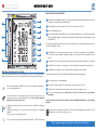 3
3
-
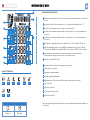 4
4
-
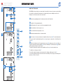 5
5
-
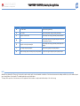 6
6
-
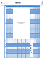 7
7
-
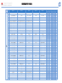 8
8
-
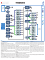 9
9
-
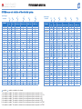 10
10
-
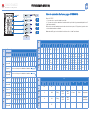 11
11
-
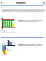 12
12
-
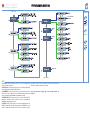 13
13
-
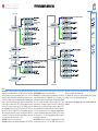 14
14
-
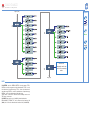 15
15
-
 16
16
-
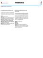 17
17
-
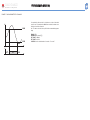 18
18
-
 19
19
-
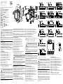 20
20
-
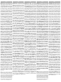 21
21
-
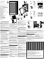 22
22
-
 23
23
-
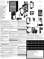 24
24
-
 25
25


CARLO GAVAZZI WM4096 Manual de usuario
- Categoría
- Iluminación de conveniencia
- Tipo
- Manual de usuario
en otros idiomas
- français: CARLO GAVAZZI WM4096 Manuel utilisateur
- italiano: CARLO GAVAZZI WM4096 Manuale utente
- English: CARLO GAVAZZI WM4096 User manual
- Deutsch: CARLO GAVAZZI WM4096 Benutzerhandbuch
Artículos relacionados
-
CARLO GAVAZZI MOA2 El manual del propietario
-
-
-
-
-
-
-
CARLO GAVAZZI EM2696AV63HR2S1XX Guía de instalación
-
-
Otros documentos
-
Amprobe ACD-51HP & ACD-56HPQ Power Quality Clamp-On Manual de usuario
-
-
 Crady CS-INV-S-METER El manual del propietario
-
Hager HTG411H Instrucciones de operación
-
KPS 810 Manual de usuario
-
Eaton E5324E Series Operating Instructions Manual
-
Big Ass Fans BAFCon Guía de instalación
-
Schneider Electric EBX510 Com’X Energy Server Guía de instalación
-
 Crady CS-INV-T-METER El manual del propietario
-
Siemens 9410DC Power Meter 9410 Manual de usuario

