Cub Cadet 21AA40M8710 Manual de usuario
- Categoría
- Mini cultivadores
- Tipo
- Manual de usuario
Este manual también es adecuado para

OperatOr’s Manual
Safe Operation Practices • Assembly & Set-Up • Controls & Operation • Service • Troubleshooting • Replacement Parts • Warranty
Record Product Information
Before setting up and operating your new equipment, please locate the model
plate and record the information in the area provided to the right. The model plate
contains the unit’s model and serial numbers. This information will be necessary,
should you seek technical support via our web site, Customer Support Department,
or with a local authorized service dealer.
Model NuMber
Serial NuMber
Form No. 769-12653A
(December 9, 2019)
WARNING
Read and follow all safety rules and instructions in this manual before attempting to operate this machine. Failure to comply with these instructions
may result in personal injury.
Safe Operation Practices .......................................................... 3
Assembly & Set-Up ................................................................... 5
Controls & Operation ............................................................... 7
Service .................................................................................. 10
Troubleshooting .....................................................................12
Replacement Parts .................................................................13
Warranty ...............................................................................14
Español ................................................................................. 16
Table of Contents
NOTE: This Operator’s Manual covers several models. Features may vary by model. Not all features in this manual are applicable to all models and the model depicted may differ
from yours.
WARNING
California Proposition 65
Engine Exhaust, some of its constituents, and certain vehicle components contain or emit chemicals known to the State of California to cause cancer and
birth defects.
Rear Tine Tiller - Model RT 45

Product Registration and Customer Support
Please register your product on our website, www.cubcadet.com.
If you have difficulty assembling this product or have any questions regarding the controls, operation, or maintenance of this machine, you can seek help from the
experts. Choose from the options below:
◊ Visit us on the web at www.cubcadet.com
◊ Locate your nearest Cub Cadet Dealer at (877) 282-8684
◊ Write to Cub Cadet LLC • P.O. Box 361131 • Cleveland, OH • 44136-0019
Thank you for purchasing this product. It was carefully engineered to provide excellent
performance when properly operated and maintained.
Please read this entire manual prior to operating the equipment. It instructs you how to safely
and easily set up, operate and maintain your machine. Please be sure that you, and any other
persons who will operate the machine, carefully follow the recommended safety practices at all
times. Failure to do so could result in personal injury or property damage.
All information in this manual is relative to the most recent product information available at
the time of printing. Review this manual frequently to familiarize yourself with the machine, its
features and operation. Please be aware that this Operator’s Manual may cover a range of product
specifications for various models. Characteristics and features discussed and/or illustrated
in this manual may not be applicable to all models. We reserve the right to change product
specifications, designs and equipment without notice and without incurring obligation.
If applicable, the power testing information used to establish the power rating of the engine
equipped on this machine can be found at www.opei.org or the engine manufacturer’s web site.
If you have any problems or questions concerning the machine, phone your local authorized Cub
Cadet service dealer or contact us directly. Cub Cadet’s Customer Support telephone numbers,
website address and mailing address can be found on this page. We want to ensure your complete
satisfaction at all times.
Throughout this manual, all references to right and left side of the machine are observed from
the operating position.
The engine manufacturer is responsible for all engine-related issues with regards to performance,
power-rating, specifications, warranty and service. Please refer to the engine manufacturer’s
Owner’s/Operator’s Manual, packed separately with your machine, for more information.
Thank You
TO THE OWNER
2

SAFE OPERATION PRACTICES
3
Training
1. Read, understand and follow all instructions on the machine and in the manual(s) before attempting
to assemble and operate. Keep this manual in a safe place for future and regular reference and for
ordering replacement parts.
2. Be familiar with all controls and their proper operation. Know how to stop the machine and disengage
it quickly.
3. Never allow children under 14 years of age to operate this machine. Children 14 and over should read
and understand the instructions and safe operation practices in this manual and on the machine and be
trained and supervised by an adult.
4. Never allow adults to operate this machine without proper instruction.
5. Keep the area of operation clear of all persons, particularly small children and pets. Stop machine if
anyone enters the area.
Preparation
1. Thoroughly inspect the area where the equipment is to be used. Remove all stones, sticks, wire and
other foreign objects which could be tripped over and cause personal injury.
2. Wear sturdy, rough-soled work shoes and close fitting slacks and shirt. Loose fitting clothes or jewelry
can be caught in moving parts. Never operate this machine in bare feet or sandals.
3. Disengage clutch levers and shift (if provided) into neutral (“N”) before starting the engine.
4. Never leave this machine unattended with the engine running.
5. Never attempt to make any adjustments while engine is running, except where specifically
recommended in the operator’s manual.
Safe Handling of Gasoline:
1. To avoid personal injury or property damage use extreme care in handling gasoline. Gasoline is
extremely flammable and the vapors are explosive. Serious personal injury can occur when gasoline is
spilled on yourself or your clothes which can ignite. Wash your skin and change clothes immediately.
• Use only an approved gasoline container.
• Never fill containers inside a vehicle or on a truck or trailer bed with a plastic liner. Always place
containers on the ground away from your vehicle before filling.
• When practical, remove gas-powered equipment from the truck or trailer and refuel it on the
ground. If this is not possible, then refuel such equipment on a trailer with a portable container,
rather than from a gasoline dispenser nozzle.
• Keep the nozzle in contact with the rim of the fuel tank or container opening at all times until
fueling is complete. Do not use a nozzle lock-open device.
• Extinguish all cigarettes, cigars, pipes and other sources of ignition.
• Never fuel machine indoors.
• Never remove gas cap or add fuel while the engine is hot or running. Allow engine to cool at
least five minutes before refueling.
• Never over fill fuel tank. Fill tank to no more than 1/2 inch below bottom of filler neck to allow
space for fuel expansion.
• Replace gasoline cap and tighten securely.
• If gasoline is spilled, wipe it off the engine and equipment. Move unit to another area. Wait five
minutes before starting the engine.
• To reduce fire hazards, keep machine free of grass, leaves or other debris build-up. Clean up oil
or fuel spillage and remove any fuel soaked debris.
• Never store the machine or fuel container inside where there is an open flame, spark or pilot
light as on a water heater, space heater, furnace, clothes dryer or other gas appliances.
Operation
1. Do not put hands or feet near rotating parts. Contact with the rotating parts can amputate hands and feet.
2. Always wear safety glasses or safety goggles during operation and while performing an adjustment or
repair to protect your eyes. Thrown objects which ricochet can cause serious injury to the eyes.
3. For extended use of this product, hearing protection is required.
4. Do not operate machine while under the influence of alcohol or drugs.
5. Never operate this machine without good visibility or light. Always be sure of your footing and keep a
firm hold on the handles.
6. Keep bystanders away from the machine while it is in operation. Stop the machine if anyone enters the
area.
7. Be careful when tilling in hard ground. The tines may catch in the ground and propel the tiller forward.
If this occurs, let go of the handle bars and do not restrain the machine.
8. Exercise extreme caution when operating on or crossing gravel surfaces. Stay alert for hidden hazards
or traffic. Do not carry passengers.
9. Never operate the machine at high transport speeds on hard or slippery surfaces.
10. Exercise caution to avoid slipping or falling.
11. Look down and behind and use care when in reverse or pulling machine towards you.
12. Start the engine according to the instructions found in this manual and keep feet well away from the
tines at all times.
13. After striking a foreign object, stop the engine, disconnect the spark plug wire and ground against
the engine. Thoroughly inspect the machine for any damage. Repair the damage before starting and
operating.
14. Disengage all clutch levers (if fitted) and stop engine before you leave the operating position (behind
the handles). Wait until the tines come to a complete stop before unclogging the tines or making any
adjustments or inspections.
15. Never run an engine indoors or in a poorly ventilated area. Engine exhaust contains carbon monoxide,
an odorless and deadly gas.
16. Muffler and engine become hot and can cause a burn. Do not touch.
17. Use caution when tilling near fences, buildings and underground utilities. Rotating tines can cause
property damage or personal injury.
18. Do not overload machine capacity by attempting to till soil too deep at too fast of a rate.
19. If the machine should start making an unusual noise or vibration, stop the engine, disconnect the spark
plug wire and ground it against the engine. Inspect thoroughly for damage. Repair any damage before
starting and operating.
20. Keep all shields, guards and safety devices in place and operating properly.
21. Never pick up or carry machine while the engine is running.
22. Use only attachments and accessories approved by the manufacturer. Failure to do so can result in
personal injury.
23. If situations occur which are not covered in this manual, use care and good judgement. Contact
Customer Support for assistance and the name of your nearest servicing dealer.
Maintenance & Storage
1. Keep machine, attachments and accessories in safe working order.
2. Allow a machine to cool at least five minutes before storing. Never tamper with safety devices. Check
their proper operation regularly.
3. Check bolts and screws for proper tightness at frequent intervals to keep the machine in safe working
condition. Also, visually inspect machine for any damage.
4. Before cleaning, repairing or inspecting, stop the engine and make certain the tines and all moving
parts have stopped. Disconnect the spark plug wire and ground it against the engine to prevent
unintended starting.
5. Do not change the engine governor settings or over-speed the engine. The governor controls the
maximum safe operating speed of engine.
6. Maintain or replace safety and instruction labels, as necessary.
7. Follow this manual for safe loading, unloading, transporting and storage of this machine.
8. Always refer to the Operator’s Manual for important details if the machine is to be stored for an
extended period.
9. If the fuel tank has to be drained, do this outdoors.
10. Observe proper disposal laws and regulations for gas, oil, etc. to protect the environment.
11. According to the Consumer Products Safety Commission (CPSC) and the U.S. Environmental Protection
Agency (EPA), this product has an Average Useful Life of seven (7) years, or 130 hours of operation. At the
end of the Average Useful Life have the machine inspected annually by an authorized service dealer to
ensure that all mechanical and safety systems are working properly and not worn excessively. Failure to
do so can result in accidents, injuries or death.
WARNING
This symbol points out important safety instructions which, if not followed, could endanger the personal safety and/or property of yourself and others. Read and
follow all instructions in this manual before attempting to operate this machine. Failure to comply with these instructions may result in personal injury. When you see
this symbol - HEED ITS WARNING!
DANGER
This machine was built to be operated according to the safe operation practices in this manual. As with any type of power equipment, carelessness or error on the part of
the operator can result in serious injury. This machine is capable of amputating hands and feet and throwing debris. Failure to observe the following safety instructions
could result in serious injury or death.

SAFE OPERATION PRACTICES
4
Notice Regarding Emissions
Engines which are certified to comply with California and federal EPA emission regulations for SORE (Small Off
Road Equipment) are certified to operate on regular unleaded gasoline, and may include the following emission
control systems: Engine Modification (EM), Oxidizing Catalyst (OC), Secondary Air Injection (SAI) and Three Way
Catalyst (TWC) if so equipped.
Spark Arrestor
WARNING
This machine is equipped with an internal combustion engine and should
not be used on or near any unimproved forest-covered, brushcovered or
grass-covered land unless the engine’s exhaust system is equipped with a
spark arrestor meeting applicable local or state laws (if any).
If a spark arrestor is used, it should be maintained in effective working order by the operator. In the State of
California the above is required by law (Section 4442 of the California Public Resources Code). Other states may
have similar laws. Federal laws apply on federal lands.
A spark arrestor for the muffler is available through your nearest engine authorized service dealer or contact the
service department, P.O. Box 361131 Cleveland, Ohio 44136-0019.
WARNING
Your Responsibility — Restrict the use of this power machine to persons who read, understand and follow the warnings and instructions in this manual and on the machine.
SAVE THESE INSTRUCTIONS!
Safety Symbols
This page depicts and describes safety symbols that may appear on this product. Read, understand and follow all instructions on the machine before attempting to assemble and operate.
Symbol Description
READ THE OPERATOR’S MANUAL(S)
Read, understand and follow all instructions in the manual(s) before attempting to assemble and operate.
WARNING— ROTATING TINES
Do not put hands or feet near rotating parts. Contact with the rotating parts can amputate hands and feet.

ASSEMBLY & SET-UP
5
Contents of Carton
• Tiller
• Handlebar Assembly
• Operator’s Manual
• Engine Operator’s Manual
NOTE: This Operator’s Manual covers several models. Garden tiller features may vary by
model. Not all features in this manual are applicable to all garden tiller models and the
garden tiller depicted may differ from yours.
WARNING
To prevent personal injury or property damage, do not start the engine
until all assembly steps are complete and you have read and understand
the Safe Operation Practices section and the Controls & Operating section
in this manual.
Assembly
Unpacking Instructions
NOTE: While unpacking, do not severely bend any of the control cables.
1. The tiller is heavy, do not attempt to remove it from the shipping platform
until instructed to do so in these assembly steps.
2. Remove all parts from the carton. Check that you have the items listed in the
Contents of Carton list (contact your local dealer or the Cub Cadet technical
service representative if items are missing or damaged).
3. Remove any packaging material from the carton. Remove any staples from
the bottom of the carton and remove the carton from the shipping platform.
Handle
NOTE: All references to the right or left side of the tiller are from the operator’s position.
1. Install the handle onto the tiller using the hardware pre-installed on the
handle mounting brackets. This consists of a ⁄-18 x 3.00 hex bolt, a handle
crank assembly, retainer bracket and two ⁄-18 flange lock nuts. Remove
this hardware from the handle mounting brackets on the tiller.
2. Insert the handle into the handle mounting brackets, lining up the pre-
drilled holes. Insert the ⁄-18 x 3.00 hex bolt in the bottom hole from the
left hand side through to the other side. Place the round hole end of the hex
retainer bracket over the hex bolt and secure loosely with a bell washer and
⁄-18 flange lock nut removed earlier.
NOTE: The bell washer should be positioned with the top of the bell shape towards
the hex nut which will create tension and further secure the flange lock nut once
tightened. Do not tighten this hardware at this time.
3. Install the handle-crank
adjustment rod into the
top hole of the mounting
bracket from the left
hand side of the handle
assembly, secure with
the other flange lock nut
previously removed. Fit
the hex end of the retainer
bracket over the flange
lock nut. See Figure 1.
4. Tighten the hex bolt
installed in Step 2 at this
time. Be careful not to
overtighten this hardware.
5. With the handle in the desired position, tighten the handle-crank
adjustment rod at this time.
Attaching the Cables
To attach the cables, follow
these steps:
1. Route the two cables
along the handle assembly
on the right-hand side. See
Figure 2.
2. Connect the reverse cable
(Red) to the reverse cable
control by feeding the
z-hook through the hole on the
reverse cable control from the inside towards the outside. Refer to Figure 2.
3. Connect the forward drive cable (Black) to the clutch bail by feeding the
z-hook through the hole on the clutch bail from the outside towards the
inside. See Figure 2.
NOTE: Test the function of the reverse clutch and forward drive bail by pulling the
reverse handle and releasing it. The handle should return to its neutral position. If it
doesn’t, contact your local dealer for technical assistance.
NOTE: To test the function of the forward drive bail, lift the bail to the handle and
release it. The bail should return to its neutral position. If it doesn’t, contact your
local dealer for technical assistance.
4. Snap the cable housing
clips into the handle
assembly cable mount as
seen here. The red clip
(reverse cable) fits into the
top position on the handle
assembly, while the black
clip (forward/clutch cable)
feeds into the lower
position on the handle
assembly. See Figure 2.
5. Clip the cables into the
cable guides located on
the handle assembly panel
as seen in Figure 3.
Installing Emergency Stop Control (If Equipped)
WARNING
Use extreme caution when reversing or pulling the machine towards you. To
avoid getting pinned against a structure, ensure adequate distance before
reversing near a wall or fence. For machines with powered reverse drive
capability, familiarize yourself with the operation of the Emergency Stop
Control. It provides a means of stopping power to the tines and wheel drive
in an emergency situation.
1. Locate the emergency stop control
wire on the right side of the unit
behind the engine.
2. Route the emergency stop control
wire up the handle shaft and secure
with cable ties slightly above the
lower handle adjust and slightly
below the handle panel. Bundle the
emergency stop control wire with the
drive cables previously installed. See
Figure 4.
Figure 1
Red
Black
Black
Red
Figure 2
Figure 3
Figure 4

ASSEMBLY & SET-UP
6
3. Slide the emergency stop
control switch wire through the
opening on the bottom right side
of the handle panel, where clutch
cables were previously routed.
See Figure 5.
4. Route the emergency stop control
wire behind the handle, then to the
left side of the handlebar. Secure
with a cable tie immediately after
routing out from behind the panel.
See Figure 6.
5. Mount the emergency stop
control ON/OFF switch onto the
left side of the handlebar with the #10-32 : 1.50 hex bolt and 10-32 flange
lock nut. See 1 in Figure 7.
6. Finally, secure the wire near the bottom of the handlebar with a cable tie
looped through the hole beside the instruction label on the left handlebar.
See 2 in Figure 7.
Move Tiller Off Crate
To roll the tiller off the shipping platform, put the wheels in FREEWHEEL, if they are
not already from the factory, as follows:
1. Place a sturdy block under
the transmission to raise
one wheel about 1” off
the ground. Remove the
click pin from the wheel
hub and wheel shaft. See
Figure 8.
2. Slide the wheel fully inward
on the wheel shaft. Reinstall
the click pin through the
wheel shaft only (not
through the wheel hub).
See Figure 8. The wheel
should now spin freely
(FREEWHEEL) on the wheel shaft. Repeat with the other wheel.
3. Use the handlebar to roll the tiller to a flat area.
NOTE: Before starting the engine, the wheels must be placed in the WHEEL DRIVE
position (pins through wheel hubs and wheel shaft).
4. Once the tiller is off the crate, place the wheels in the WHEEL DRIVE position.
Remove the click pin, slide the wheel outward until the hole on the wheel
hub aligns with the hole on the drive shaft and reinstall the click pin.
Set-Up
Tire Pressure
Check the air pressure with a tire gauge. Deflate or inflate the tires equally to
between 15 and 20 w. DO NOT EXCEED 20 P.S.I.
NOTE: Be sure that both tires are inflated equally or the tiller will pull to one side.
Gas & Oil Fill Up
WARNING
Use extreme care when handling gasoline. Gasoline is extremely flammable
and the vapors are explosive. Never fuel the machine indoors or while the
engine is hot or running. Extinguish cigarettes, cigars, pipes and any other
sources of ignition.
Service the engine with gasoline and oil as instructed in the Engine Operator’s
Manual packed separately with your tiller. Read the instructions carefully.
Figure 5
Figure 6
1
2
Figure 7
Remove the
click pin from
the wheel hub
Slide the wheel fully
inward on the wheel
shaft. Reinstall the
click pin
Click Pin
Figure 8

CONTROLS & OPERATION
7
Controls
NOTE: This Operator’s Manual covers several models. Garden tiller features may vary by
model. Not all features in this manual are applicable to all garden tiller models and the
garden tiller depicted may differ from yours.
WARNING
Before operating your machine, carefully read and understand all safety, controls
and operating instructions in this manual and on the decals on the machine.
Failure to follow these instructions can result in serious personal injury.
Reverse Handle (IF EQUIPPED)
The Reverse Handle controls the reverse drive of the wheels and tines.
Forward Clutch Bail & Tine Engagement
The forward clutch bail controls the engagement of the forward drive of the wheels
and tines.
Depth Regulator Lever
This lever controls the tilling depth of the tines. Pull the lever back and slide it up or
down to engage the notched height settings.
Handlebar Height Adjustment
The handlebar height is adjustable to three different settings. In general, adjust the
handlebars so they are at waist level when the tines are 3-4” in the ground.
Rear Tine Shield
The rear tine shield protects the operator from flying debris while also smoothing
out freshly tilled soil.
Side Shield
The side shield is used to maintain clear even rows and may be adjusted to one of
five different positions.
Tines
Your tiller’s tines are a series of hoes arranged on a revolving power-driven shaft.
Wheel Drive Pins
Each wheel is equipped with a wheel drive click pin that secures
the wheel to the wheel shaft. The wheels can be positioned in
either a WHEEL DRIVE or a FREEWHEEL mode.
Emergency Stop Control (IF EQUIPPED)
The emergency stop control is a switch used to stop the tiller
engine and tiller functions from the operator’s position in
emergency situations.
NOTE: Some engine models may also come equipped with an ignition
ON/OFF switch. Consult the separate Engine Operator’s Manual.
Operation
WARNING
Before operating your machine, carefully read and
understand this manual and all of its safety, operating and
maintenance sections and instructions, along with all of the
decals on the machine. Failure to follow these instructions
can result in serious personal injury.
Read this Operation Section and the Engine Operator’s Manual
before you start the engine. Then, take the time to familiarize
yourself with the basic operation of the tiller before using it in
the garden.
Find an open, level area and practice using the tiller controls without the tines
engaging the soil (put tines in “transport” setting).
Only after you’ve become completely familiar with the tiller should you begin using
it in the garden.
To Put The Tines in
Transport:
Pull back on the depth
adjustment bracket (A) and push
down (B) until the bracket reaches
the highest notch. See Figure 10.
Then release the bracket (C).
Break-In Operation
Perform the following
maintenance after the first five
(5) hours of new operation (see
the Service section in this manual).
1. Change engine oil.
2. Check for loose or missing hardware on unit. Tighten or replace as needed.
3. Check transmission gear oil level.
Starting & Stopping the Engine
Pre-Start Checklist
With the spark plug wire disconnected from the spark plug, perform the following
checks and services before each use:
1. Read the Safe Operation Practices section in this manual. Read the Controls
Section in this manual. Read the Engine Operator’s Manual.
2. Put the wheels in the WHEEL DRIVE position (wheel pins must be through
the holes in the wheel hubs and the wheel shaft).
3. Check unit for loose or missing hardware. Service as required.
Forward Clutch Bail
& Tine Engagement
Reverse Handle
Tines
Side Shield
Rear Tine Shield
Wheel Drive Pin
Depth Regulator
Handle Height Adjustment
Emergency Stop
Control (If Equipped)
Figure 9
A
B
C
Figure 10

CONTROLS & OPERATION
8
4. Check engine oil level. See Engine Operator’s Manual.
5. Check that all safety guards and covers are in place.
6. Check air cleaner and engine cooling system. See the Engine Operator’s Manual.
WARNING
GASOLINE IS HIGHLY FLAMMABLE AND ITS VAPORS ARE EXPLOSIVE. Follow the
gasoline safety rules in the Safe Operation Practices section of this manual.
Failure to follow gasoline safety instructions can result in serious personal injury
and property damage.
7. Fill the fuel tank with gasoline according to the directions in the Engine
Operator’s Manual. Follow all instructions and safety rules carefully.
8. Attach the spark plug wire to the spark plug.
Starting & Stopping the Engine
WARNING
To help prevent serious personal injury or damage to equipment, put both wheels
in the WHEEL DRIVE position. Never have wheels in FREEWHEEL position when the
engine is running. When the wheels are in FREEWHEEL, they do not hold back the
tiller and the tines could propel the tiller rapidly forward or backward. Put the
Forward Clutch Bail in the neutral (disengaged) position by releasing the lever.
WARNING
Never run the engine indoors or in an enclosed, poorly ventilated area. Engine
exhaust contains carbon monoxide, an odorless and deadly gas. Avoid the engine
muffler and nearby areas. Temperatures in these areas may exceed 150° F.
1. Complete the Pre-Start Checklist above.
2. Put the wheels in the WHEEL DRIVE position by removing the click pins, sliding
the wheel all the way in and reinstalling the click pin through the wheel hubs
and wheel shaft.
3. Move the Depth Regulator Lever all the way down to the “transport”
position, so that the tines clear the ground.
4. Release all of the controls on the tiller.
5. If equipped with an emergency stop
control switch, make sure that the
emergency stop control is set to
the ON position, represented by the
solid line while attempting to start
the engine. See Figure 11.
6. Start the engine as instructed in the
Engine Operator’s Manual.
IMPORTANT:
If equipped with an emergency
stop control switch, verify the stop control
function works properly before each use by
moving the switch to the OFF position with the engine running. Only continue operation if the
emergency stop control switch stops the engine.
Using Emergency Stop Control (If Equipped)
To stop the running engine using the emergency stop control, move the switch to the
OFF position, represented by the circle. See Figure 11.
To Engage Drive & Tines
1. For forward motion of the wheels and power to the tines pull the Forward
Clutch Bail up against the handlebar. Release the bail to stop the forward
motion of wheels and tines.
2. When tilling, relax and let the wheels pull the machine while the tines dig.
Walk behind and a little to one side of the tiller. Use one hand, yet keep a
light — but secure — grip on the handlebar while keeping your arm loose.
3. Let the tiller move at its own pace and do not push down on the
handlebars to try and force the tines to dig deeper — this takes weight off
the wheels and reduces traction.
WARNING
Do not push down on the handlebars to try to make the tiller till more deeply.
This prevents the wheels from holding the tiller back and can allow the tines to
rapidly propel the tiller forward, which could result in loss of control, property
damage or personal injury.
To stop/disengage the drive/tines release the Forward Clutch Bail.
To move in reverse:
1. Release the Forward Clutch Bail. Then lift the handlebar until the tines are
off the ground.
2. Pull back on the Reverse Lever, and walk backwards with the machine.
NOTE: In reverse mode, the tines will reverse rotation.
3. If longer distances need to be covered in reverse, shut off the engine, then
place the two wheels in FREEWHEEL.
Turning the Tiller
1. Practice turning the tiller in a level, open area. Be very careful to keep your
feet and legs away from the tines.
2. To begin a turn, lift the handlebars until the tines are out of the ground and
the engine and tines are balanced over the wheels.
3. With the tiller balanced, push sideways on the handlebar to steer in the
direction of the turn. After turning, slowly lower the tines into the soil to
resume tilling.
Setting The Depth
Tilling depth is controlled by the depth stake which can be adjusted to five different
settings. Adjust the side shields as you adjust the depth stake.
WARNING
Be certain the spark plug wire is disconnected and grounded against the engine
when performing any adjustments.
• When using the tiller for the first time, use the second adjustment hole from
the top (1” of tilling depth).
• When breaking up sod and for shallow cultivation, use the setting which
gives 1” of tilling depth (second hole from the top). Place the side shields in
their lowest position.
• For further depth, raise the depth stake and side shields and also make one
or two more passes over the area.
• When tilling loose soil, the depth stake may be raised to its highest position
(use bottom adjustment hole) to give the deepest tilling depth. Raise the
side shields to the highest position.
• To transport tiller, lower the depth stake (use top adjustment hole).
To adjust the depth stake, pull back
on the depth adjustment bracket
(A) and push up or down (B) until
the bracket reaches the desired
position, see Figure 9, then release
the bracket (C).
To adjust the side shields (if
equipped), remove the wing nuts.
Move the side shield to the desired
position and replace the wing nuts.
Tighten securely. See Figure 12.
ON (Ignition)
OFF
Figure 11
Figure 12

CONTROLS & OPERATION
9
Adjusting the Handle Height
The handle should be adjusted
so that when the tiller is digging
3-4” into the soil, the handle falls
to about waist-high. To adjust the
handle, simply loosen the handle
adjustment crank, move the
handle to the desired height and
retighten the adjustment crank.
See Figure 13.
Tilling Tips &
Techniques
Tilling Depth
WARNING
Before tilling, contact your telephone or utilities company and inquire if
underground equipment/lines are used on your property. Do not till near buried
electric cables, telephone lines, pipes or hoses.
• This is a CRT (counter-rotating tine) tiller. As the wheels pull forward, the tines
rotate backward. This creates an “uppercut” tine action which digs deeply,
uprooting soil and weeds. Don’t overload the engine, but dig as deeply as
possible on each pass. On later passes, the wheels may tend to spin in the soft
dirt. Help them along by lifting up slightly on the handlebar (one hand, palm
up, works most easily).
• Avoid the temptation to push down on the handlebars in an attempt to force the
tiller to dig deeper. Doing so takes the weight off the powered wheels, causing
them to lose traction. Without the wheels to hold the tiller back, the tines will
attempt to propel the tiller backward, towards the operator.
• When cultivating (breaking
up the surface soil around
the plants to destroy weeds,
see Figure 14), adjust the
tines to dig only 1” to 2”
deep. Using the shallow
tilling depth helps prevent
injury to the plants whose
roots often grow close
to the surface. If needed,
lift up on the handlebars
slightly to prevent the tines
from digging too deeply.
(Cultivating on a regular
basis not only eliminates weeds, it also loosens and aerates the soil for better
moisture absorption and faster plant growth.) Watering the garden area a few
days prior to tilling will make tilling easier, as will letting the newly worked soil set
for a day or two before making a final, deep tilling pass.
Choosing Correct Wheel & Tine Speeds
With experience, you will find the tilling depth and tilling speed combination that
is best for your garden. Set the engine throttle lever at a speed to give the engine
adequate power and yet allow it to operate at the slowest possible speed until you
have achieved the maximum tilling depth you desire. Faster engine speeds may
be desirable when making final passes through the seedbed or when cultivating.
Selection of the correct engine speed, in relation to the tilling depth, will ensure a
sufficient power level to do the job without causing the engine to labor.
Clearing the Tines
• The tines have a self-clearing action which eliminates most of the tangling
of debris. However, occasionally dry grass, stringy stalks or tough vines may
become tangled. Follow these procedures to help avoid tangling and to clear
the tines, if necessary.
• To reduce tangling, set the depth regulator deep enough to get maximum
“chopping” action as the tines chop the material against the ground. Also, try
to till under crop residues or cover crops while they are green, moist and tender.
• While tilling, try swaying the handlebars from side to side (about 6” to 12”).
This “fishtailing” action often clears the tines of debris.
WARNING
Before clearing the tines by hand, stop the engine, allow all moving parts to stop
and disconnect the spark plug wire. Failure to follow this warning could result in
personal injury.
Loading & Unloading the Tiller
WARNING
Loading and unloading the tiller into a vehicle is potentially hazardous and
doing so is not recommended unless absolutely necessary, as this could result in
personal injury or property damage.
However, if you must load or unload the tiller, follow the guidelines below.
• Before loading or unloading the tiller, stop the engine, wait for all parts to stop
moving, disconnect the spark plug wire and let the engine and muffler cool.
• The tiller is too heavy and bulky to be safely lifted by one person. Two or
more people should share the load.
• Use sturdy ramps and manually — with the engine shut off — roll the tiller
into and out of the vehicle. Two or more people are needed to do this.
• The ramps must be strong enough to support the combined weight of the
tiller and any handlers. The ramps should provide good traction to prevent
slipping; they should also have side rails to guide the tiller along the ramps;
and they should have a locking device to secure them to the vehicle.
• The handlers should wear sturdy footwear that will help to prevent slipping.
• Position the loading vehicle so that the ramp angle is as flat as possible (the
less incline to the ramp, the better). Turn the vehicle’s engine off and apply
the parking brake.
• When going up the ramps, stand in the normal operating position and push
the tiller ahead of you. Have a person at each side to turn the wheels.
• When going down the ramps, walk backward with the tiller following you.
Keep alert for any obstacles behind you. Position a person at each wheel to
control the speed of the tiller. Never go down the ramps tiller-first, as the
tiller could tip forward.
• Place wooden blocks on the downhill side of the wheels if you need to stop
the tiller from rolling down the ramp. Also, use the blocks to temporarily
keep the tiller in place on the ramps (if necessary), and to chock the wheels
in place after the tiller is in the vehicle.
• After loading the tiller, prevent it from rolling by engaging the wheels in the
WHEEL DRIVE position. Chock the wheels with blocks and securely tie the
tiller down.
Figure 13
Figure 14

SERVICE
10
WARNING
Before inspecting, cleaning or servicing the machine, shut off the engine,
wait for all moving parts to come to a complete stop, wait for the engine
to cool, disconnect the spark plug wire and move the wire away from
the spark plug. Failure to follow these instructions can result in serious
personal injury or property damage.
Maintenance
Engine
Refer to the Engine Operator’s Manual for all engine maintenance.
Tire Pressure
Check the air pressure in both tires. The air pressure should be between 15-20 PSI.
Keep both tires equally inflated to help prevent machine from pulling to one side.
Hardware
Check for loose or missing hardware after every 10 operating hours and tighten or replace
— as needed — before reusing the tiller.
Be sure to check the screws underneath the tiller hood that secure the transmission
cover and the Depth Regulator Lever to the transmission.
Transmission Gear Oil
Check the transmission gear oil after every 30 hours of operation to whenever you
notice any oil leak. Operating the tiller when the transmission is low on oil can result
in severe damage.
To Check the Transmission Gear Oil Level:
1. Check the gear oil level
when the transmission is
cool. Gear oil will expand
in warm operating
temperatures and this
expansion will provide an
incorrect oil level reading.
2. With the tiller on level
ground, pull the Depth
Regulator Lever all the
way up.
3. Remove the oil fill plug
from the transmission
housing and look inside
the oil fill hole to locate the main drive shaft situated below the hole. See
Figure 15.
4. The gear oil level is correct if the gear oil is approximately halfway up the
side of the main drive shaft.
5. If the gear oil level is low, add gear oil as described next. If the gear oil level
is okay, securely replace the oil fill plug.
6. If adding only a few ounces of gear oil, use API rated GL-4 or GL-5 gear oil
having a viscosity of SAE 140, SAE 85W-140 or SAE 80W-90. If refilling an
empty transmission, use only GL-4 gear oil having a viscosity of SAE 85W-140
or SAE 140.
7. While checking frequently to avoid overfilling, slowly add gear oil into the oil
fill hole until it reaches the halfway point on the drive shaft.
8. Securely replace the oil fill plug.
Lubrication
After every 10 operating hours,
oil or grease the lubrication
points shown in Figure 16 and
described below.
Use clean lubricating oil (#30
weight motor oil is suitable) and
clean general purpose grease
(grease containing a metal
lubricant is preferred, if available).
• Remove the wheels, clean
the wheel shaft and apply
a thin coating of grease.
• Grease the back, front and
sides of the Depth Regulator Lever.
• Remove the tines and clean the tine shaft. Use a file or sandpaper to gently
remove any rust, burrs or rough spots (especially around the holes in the
shaft). Apply grease to the ends of the shaft before installing the tines.
• Oil the threads on the handlebar height adjustment screws and the
handlebar attaching screws.
Off-Season Storage
When the tiller won’t be used for an extended period, prepare it for storage as
follows:
1. Clean the tiller and engine.
2. Do routine tiller lubrication and check for loose parts and hardware.
3. Change the engine oil and filter following the instructions provided in the
engine manual packed with this manual.
WARNING
Never store the tiller with fuel in the tank indoors or in poorly ventilated
enclosures, where fuel fumes may reach an open flame, spark or pilot light
as on a furnace, water heater, clothes dryer, etc.
4. If storing the tiller for 30 days or more:
a. To prevent gum deposits from forming inside the engine’s carburetor
and causing possible malfunction of the engine, the fuel system
must be either completely emptied, or the gasoline must be treated
with a stabilizer to prevent deterioration.
WARNING
Fuel left in the fuel tank deteriorates and will cause serious starting problems.
b. Using a fuel stabilizer for storage between 30 and 90 days:
• Read the product manufacturer’s instructions and
recommendations.
• Add to clean, fresh gasoline the correct amount of stabilizer
for the capacity (approximately 3 gallons) of the fuel system.
• Fill the fuel tank with treated fuel and run the engine for 2-3
minutes to get stabilized fuel into the carburetor.
c. Emptying the fuel system for storage of more than 90 days:
• Prior to putting the tiller in storage, monitor fuel
consumption with the goal of running the fuel tank empty.
• Run the engine until it begins to stall. Use the choke to keep
the engine running until all fuel in the carburetor has been
exhausted.
• Referring to the engine manual, drain the fuel from the
carburetor bowl.
5. Store the tiller in a clean, dry area.
Figure 15
Handlebar Hardware
Depth Regulator Lever
Wheel Shaft
Tine Shaft
Figure 16

SERVICE
11
6. Never store the tiller with fuel in the fuel tank in an enclosed area where
gas fumes could reach an open flame or spark, or where ignition sources are
present (space heaters, hot water heaters, furnaces, etc.).
Belt Replacement
If the drive or reverse belts need to be replaced, it is best to replace both belts at the
same time. Use only a factory-authorized belt as an “over- the-counter” belt may
not perform satisfactorily. The procedure requires average mechanical ability and
commonly available tools.
To replace the drive and reverse
belts, follow these steps:
1. Make sure the tiller is on a
flat surface, with the
engine turned off and the
spark plug wire
unplugged and grounded
to prevent unintended
firing of the engine.
2. Remove the belt cover as
seen in Figure 17, by first
removing the two 1⁄4-20
hex washer screws and
one flat washer. Lift the
belt cover up and away
from the tiller and set
in a safe location until
reinstallation.
3. Remove the four 1⁄4-20
hex washer screws that
secure the pulley shield
to the frame as seen in
Figure 18, and remove the
pulley shield and set aside
in a safe location until
reinstallation.
4. Remove the idler bracket
extension spring, as
pointed out in Figure 19. It
is recommended to use a
pair of needle-nosed
pliers, and grab the spring
by the end that hooks over
the frame. Simply grab it
and pull it away from the
frame, then upwards and
carefully relieve the
tension of the spring.
5. Remove the idler pulley
bracket by removing the
5⁄16-24 hex screw, flat
washer and lock washer,
as in Figure 20.
NOTE: It will be necessary to
remove the belt from around
the idler pulley by working it off
the pulley and from underneath
each belt keeper.
6. Remove the flange nut
securing the transmission
drive pulley, then remove
the pulley along with the
two belts. See Figure 21.
7. Replace the old belts with
the new belts in the same
order they were removed.
The longer belt (754-
04091) belongs closer to
the engine (V-side out),
with the shorter belt
(754-04090) positioned
closer to the tines.
8. Reinstall the transmission drive pulley with the new belts.
9. Reassemble the tiller in the reverse order in which it was disassembled.
NOTE: When reinstalling the belt cover, be sure to engage the bail and hold it so that the drive belt
is tight before attempting to reinstall the belt cover. This will enable the belt to fall under the belt
keeping mechanism built into the belt cover. Failure to do so could damage the belt and/or belt cover.
Tines
The tines will wear with use and should be inspected at the beginning of each tilling
season and after every 30 operating hours. The tines can be replaced. Refer to the
Replacement Parts section for part numbers and ordering instructions.
Tine Inspection
With use, the tines will become shorter, narrower and pointed. Badly worn tines
will result in a loss of tilling depth and reduced effectiveness when chopping up and
turning under organic matter.
Removing/Installing a Tine Assembly
1. Remove the tine shield end covers and side shields by removing the three
wing nuts on each side that secure them.
2. A tine assembly consists of a left hand tine assembly and a right hand tine
assembly.
NOTE: The tine assembly moves in a counter-rotating motion with the sharp edges of the
tines positioned to enter the soil first when counter-rotating. Note this position of the tines for
reinstallation of the new tine assemblies.
3. To remove a tine assembly,
simply remove the cotter
pin securing the clevis
pin as seen in Figure 22.
Remove the clevis pin and
slide the assembly to the
outside of the unit and off
of the tine shaft.
4. Before reinstalling the
tine assembly, inspect the
tine shaft for rust, rough
spots or burrs. Lightly file
or sand, as needed. Apply
a thin coat of grease to
the shaft.
5. Install each tine assembly so that the cutting (sharp) edge of the tines will
enter the soil first when the tiller moves forward. Keep in mind that these
tines are counter rotating, so secure the tine assembly to the tine shaft using
the clevis pin and internal cotter pin.
Change Transmission Gear Oil
NOTE: The transmission gear oil does not need to be changed unless it has been contaminated with
dirt, sand or metal particles.
See an authorized service dealer to have the transmission gear oil changed. Refer to
the phone number on page 2 of this manual to locate the nearest service dealer.
Hex Washer
Screw
Hex
Washer
Screw
Flat Washer
Figure 17
Hex Washer
Screw
Figure 18
Remove the
idler bracket
extension
spring
This belt
should be
installed with
the V-side out
Figure 19
Remove the
idler pulley
bracket by
removing the
hex screw,
flat and lock
washers.
Remove the
belt from the
idler pulley
by working it
under the belt
keepers.
Figure 20
Flange Nut
Remove
pulley with
belts
V-side out
Figure 21
Clevis Pin
Cotter Pin
Figure 22

TROUBLESHOOTING
12
Problem Cause Remedy
Wheels/Tines will not turn 1. Improper use of controls.
2. Worn, broken or misadjusted drive belt(s).
3. Internal transmission wear or damage.
4. Bolt loose in transmission pulley.
1. Review Controls & Operation section.
2. Replace or adjust belts.
3. Contact authorized service dealer.
4. Tighten bolt.
Tines turn, but wheels don’t 1. Wheel Drive Pins not in WHEEL DRIVE.
2. Bolt loose in transmission pulley.
3. Internal transmission wear or damage.
1. Inserts Drive Pins properly.
2. Tighten bolt.
3. Contact authorized service dealer.
Wheels turn, but tines don’t 1. Tine holder mounting hardware missing.
2. Bolt loose in transmission pulley.
3. Internal transmission wear or damage.
1. Replace hardware.
2. Tighten bolt.
3. Contact authorized service dealer.
Poor tilling performance 1. Worn tines.
2. Improper Depth Regulator setting.
3. Forward Drive Belt slipping.
1. Replace Tines.
2. See “Tilling Tips & Techniques.”
3. See Service Section.

REPLACEMENT PARTS
13
Component Part Number and Description
754-04090 Reverse V-Belt
754-04091 Forward V-Belt
746-04506 Forward Drive Cable
746-04504 Reverse Drive Cable
642-04072 4-Point Tine Assembly (RH)
642-04071 4-Point Tine Assembly (LH)
711-0415 Clevis Pin, .375 x 1.75
714-04043 Internal Cotter Pin
634-04736 Wheels, 13 x 5 x 6
714-0143A Click Pin, .25 x 1.56
Cub Cadet Genuine Parts can be ordered through your local authorized Cub Cadet dealer, online at cubcadet.com or by phone at 1-800-965-4Cub.
To locate your nearest authorized Cub Cadet dealer, visit cubcadet.com or call 1-877-282-8684.

CUB CADET LLC LIMITED WARRANTY
100016 Rev D (November 8, 2019)
The limited warranty set forth herein is given by Cub Cadet LLC with respect to a new Cub Cadet® product (hereinafter “Product”) purchased and used in the
United States and/or Canada to the Initial Purchaser (as defined herein). This limited warranty does not cover Emission Control Systems and is not a Federal
Emission Control Warranty Statement, as defined by U.S. federal law. Please refer to the Federal Emission Control Warranty Statement in the operator’s manual
for warranties covering Emission Control Systems.
Scope of the Limited Warranty
Cub Cadet LLC warrants that the Product (except with regard to the components and circumstances defined below as “Exclusions”) will be free from defects in
materials and workmanship during the Warranty Period, as defined below. For purposes of this limited warranty, the “Initial Purchaser” is the first person/company
to purchase this new Product from an authorized Cub Cadet dealer, distributor, and/or retailer of such products, including a party for whom said Product was
purchased as a gift. This limited warranty is non-transferrable. During the Warranty Period, Cub Cadet LLC will, at its option, either repair or replace any original
part that is covered by this limited warranty and is determined to be defective in workmanship or material. “Commercial Use” shall be defined as any commercial,
professional, agricultural, institutional, or income-producing use of the Product. See notes below as to Commercial Use Warranty.
Cub Cadet® Warranty Information
Handheld Product* Warranty Period
Chainsaws, Cultivators, Blowers, Brushcutters, Trimmers 3 Year
Wheeled Chore and Snow Product*
Chipper-Shredders, Chipper-Shredder Vacuums, Blowers, Log Splitters, Snow Blowers 3 Year
Tillers, String Trimmers, Lawn Edgers, Pressure Washers CC3224, CC3425 & CC4033 3 Year†
Pressure Washers 2 Year†
Battery Powered Product
CC 30 e, XT1 LT42 e, RZT S Zero 3 Year†
CC30 e & XT1 LT42 e Batteries 4 Year†
Gas Powered Product
Ultima ZTX Series 4 Year/500 hour (whichever comes first)
Z-Force SX 4 Year/500 hour (whichever comes first)
Walk-Behinds, Wide-Area Walk-Behinds, CC30 Riders, XT1 & XT2 Enduro Series, RZT S/SX, Ultima ZT Series,
Z-Force S
3 Year†
23” Walk-Behinds, XT3 Enduro Series 4 Year†
Rotary Spreader 1 Year
Gas Blowers, PRO HW 2 Year
PRO Z 100 S 4 Year/500 hour (whichever comes first)
PRO Z 500/700/900, TANK LZ/SZ 3 Year
Utility Vehicle*
Challenger Series, Volunteer Series 1 Year
Additional Warranty Notes
Lead-Acid Batteries: Are covered by a one (1) year prorated limited warranty against defects in material and workmanship, with 100% replacement during the
first three (3) months, from the date of original purchase by the Initial Purchaser. After three (3) months, the battery replacement credit is based on the months
remaining in the twelve (12) month period, dating back to the date of original purchase by the Initial Purchaser. Any replacement battery will be warranted
only for the remainder of the original warranty period.
Frames: The frame, chassis, and front axle on all XT1, XT2 and XT3 products are covered for “Residential Use” by a five (5) year limited warranty. The frame on
all Ultima ZT and ZTX series products are covered for “Residential Use” by a seven year Limited Lifetime Warranty.
Mowing Decks: 1) Cub Cadet LLC warrants the mowing decks under the warranty of the product it came with unless otherwise stated. 2) When so equipped,
the optional fabricated cutting deck shell (excluding wear parts, etc. thereon) shall be warranted against defects in material and workmanship for the lifetime
of the product, namely for as long as it is owned by its Initial Purchaser or the party for whom it was originally purchased as a gift, or seven (7) years from the
date of its initial sale to an Initial Purchaser, whichever comes first. 3) The deck shell, deck spindles, and deck steel pulleys (collectively the “Deck Assembly”) on
PRO Z 500 / 700 / 900 product only, shall also be warranted to be free from defects in material and workmanship for up to an additional two (2) years (a total
of five (5) years from date of purchase) or 1,750 cumulative hours of operation, whichever comes first. For purposes of clarity, no hour limitation applies during
the initial three (3) year period described above.
Snow Blowers: Three-Stage and Two-Stage HP - Aluminum auger gear boxes have a five (5) year limited warranty.
CORE® Powered Product: Please refer to warranty with Operator’s Manual.
L and S Series: RZT L/LX, Z-Force L/LX/SZ, PRO Z 100 L, Z-Force Commercial (LZ/SZ), and Tank (L/S): Please refer to warranty included with Operator’s
Manual.
Attachments/Accessories: Please refer to warranty with Operator’s Manual.
*Limited Commercial Use Warranty: Handheld products – 90 days; Chipper-Shredder Vacuums, Blowers, Log Splitters, Snow Blowers – 1 year;
Utility Vehicle – 6 month.
† No Commercial Use Warranty: Tillers, String Trimmers, Lawn Edgers, Pressure Washers, Battery Powered Product, Walk Behind Mowers, CC30 Riders,
Enduro Series, RZT S/SX, Ultima ZT Series, and Z-Force.
The limited warranty is non-transferrable

How to Get Service Under This Limited Warranty
In order to qualify for the limited warranty, as set forth herein, the repairs
made under this warranty must be performed by an authorized Cub Cadet
service provider. To locate a Cub Cadet service provider, contact your
authorized Cub Cadet dealer, distributor, or retailer, or contact Cub Cadet LLC
at P.O. Box 368023, Cleveland, Ohio 44136-0019, or call 1-877-282-8684, or log
on to our Website at www.cubcadet.com. For Canada, contact MTD Products
Limited, 97 Kent Ave, Kitchener, ON N2G 3R2, or call 1-800-668-1238, or log on
to our Website at www.cubcadet.ca. This limited product warranty is provided
by Cub Cadet LLC and is the only product warranty provided by Cub Cadet LLC
for the Product. A COPY OF YOUR SALES RECEIPT IS REQUIRED FOR WARRANTY
SERVICE.
What This Limited Warranty Does Not Cover
This limited warranty does not cover the following (the “Exclusions”):
1. Product purchased outside of the United States or Canada.
2. Emission Control Systems. These items are subject to a separate warranty
under the applicable Federal Emission Control Warranty Statement.
Please refer to the applicable Federal Emission Control Warranty
Statement for terms and conditions relating to Emission Control Systems.
3. Damage due to lack of maintenance and/or improper maintenance, as
described in the operator’s manual.
4. Normal wear and tear resulting from use of the Product.
5. Normal Wear Parts (as defined herein) are warranted to be free from
defects in material and workmanship for a period of thirty (30) days from
the date of original purchase by the Initial Purchaser for residential use,
and for 30 days or 100 hours (whichever occurs first) for Product used
commercially. Depending on Product, Normal Wear Parts include, but
are not limited to items such as: belts, blades, blade adapters, grass bags,
rider deck wheels, seats, shave plates, skid shoes, tines, filters, nozzles,
hoses, O-rings, spray guns, wands, tires, spark plugs, fuses, bump knobs,
outer spools, cutting line, inner belts, starter pulley, starter rope, drive
belts, saw chains, guide bars, and other consumable items.
6. Log splitter pumps, valves, and cylinders are covered for a period of one
(1) year.
7. Use of the product that is not consistent with the intended use thereof,
as described in the operating instructions, including, but not limited
to, abuse, misuse and/or neglect of the Product, or any use inconsistent
with and/or non-compliant with instructions contained in the Operator’s
Manual. This includes operation in sandy and/or corrosive environments.
8. Any Product that has been altered or modified in a manner not
consistent with the original design of the Product or in a manner not
approved by Cub Cadet LLC.
9. Paint repairs or replacements for defective paint (including materials and
application) are covered for a period of three (3) months.
10. Wheel rims (when so equipped) are covered for a period of three (3)
months for manufacturing defects.
This warranty does not cover, and Cub Cadet LLC disclaims any
responsibility for, matters including, but not limited to, the following:
1. Loss of time or loss of use of the Product.
2. Transportation costs and other expenses incurred in connection with the
transport of the Product to and from the authorized Cub Cadet service
provider.
3. Any loss or damage to other equipment or personal items.
4. Damages caused by improper maintenance or the use of other than the
specified fuel, oil, or lubricants, as approved in the operator’s manual.
5. Damage resulting from the installation or use of any accessory or part not
approved by Cub Cadet LLC for use with the Product.
Limitations
1. THERE ARE NO IMPLIED WARRANTIES, INCLUDING, BUT NOT
LIMITED TO, ANY IMPLIED WARRANTY OF MERCHANTABILITY OR
FITNESS FOR A PARTICULAR PURPOSE. NO WARRANTY SHALL
APPLY AFTER THE APPLICABLE WARRANTY PERIOD, AS SET FORTH
ABOVE, AS TO THE PARTS AS IDENTIFIED. NO OTHER EXPRESS
WARRANTY OR GUARANTY, WHETHER WRITTEN OR ORAL, EXCEPT
AS MENTIONED ABOVE, GIVEN BY ANY PERSON OR ENTITY,
INCLUDING A DEALER OR RETAILER, WITH RESPECT TO ANY,
PRODUCT SHALL BIND CUB CADET LLC. DURING THE WARRANTY
PERIOD, THE EXCLUSIVE REMEDY IS REPAIR OR REPLACEMENT OF
THE DEFECTIVE PART, AS SET FORTH ABOVE. (SOME STATES DO
NOT ALLOW LIMITATIONS ON HOW LONG AN IMPLIED WARRANTY
LASTS, SO THE ABOVE LIMITATION MAY NOT APPLY TO YOU.)
2. THE PROVISIONS, AS SET FORTH HEREIN, PROVIDE THE SOLE
AND EXCLUSIVE REMEDY ARISING FROM THE SALE. CUB CADET
LLC SHALL NOT BE LIABLE FOR INCIDENTAL OR CONSEQUENTIAL
LOSS OR DAMAGES INCLUDING, WITHOUT LIMITATION, FOR
TRANSPORTATION OR FOR RELATED EXPENSES, OR FOR RENTAL
EXPENSES TO TEMPORARILY REPLACE A WARRANTED PRODUCT.
(SOME STATES DO NOT ALLOW THE EXCLUSION OR LIMITATION
OF INCIDENTAL OR CONSEQUENTIAL DAMAGES, SO THE ABOVE
EXCLUSION OR LIMITATION MAY NOT APPLY TO YOU.)
3. IN NO EVENT SHALL RECOVERY OF ANY KIND BE GREATER THAN
THE AMOUNT OF THE PURCHASE PRICE OF THE PRODUCT SOLD.
ALTERATION OF THE SAFETY FEATURES OF THE PRODUCT SHALL
VOID THIS LIMITED WARRANTY. YOU ASSUME THE RISK AND
LIABILITY FOR LOSS, DAMAGE, OR INJURY TO YOU AND YOUR
PROPERTY, AND/OR TO OTHERS AND THEIR PROPERTY, ARISING
OUT OF THE USE OR MISUSE OR INABILITY TO USE THE PRODUCT.
4. This limited warranty extends to the Initial Purchaser only and,
except as otherwise stated herein, the applicable Warranty
Period will begin on the original date of purchase of the Product.
In the event that the original date of purchase of the Product is
indeterminable, then the Warranty Period shall be established as
beginning on the Product’s date of manufacture, as determined
by Cub Cadet LLC, and ending six (6) months after the applicable
Product Warranty Period, as defined above. In no event shall a
Product’s warranty extend beyond the applicable Warranty Period.
How State Law Relates to This Warranty
This limited warranty gives you specific legal rights, and you may also
have other rights, which vary from state to state.
100016 Rev D (November 8, 2019)

Manual del OperadOr
Medidas de seguridad • Montaje y Conguración • Controles y Funcionamiento • Servicio • Solución de problemas • Garantía
Registro de información de producto
Antes de instalar y hacer funcionar su equipo nuevo, por favor localice la placa de
modelo en el equipo y registre la información en el espacio de la derecha. Necesitará
esta información para solicitar soporte técnico a través de nuestro sitio web, el
Departamento de Atención al Cliente, o de un distribuidor local de servicio autorizado.
núMerO de MOdelO
núMerO de serie
Formulario No. 769-12653A
(9 de diciembre de 2019)
ADVERTENCIA
Lea y respete todas las normas de seguridad e instrucciones incluidas en este manual antes de poner en funcionamiento esta máquina. Si no respeta
estas instrucciones puede provocar lesiones personales.
Cultivadora de dientes traseros — Modelo RT 45
Medidas de seguridad ............................................................ 18
Montaje y Configuración ........................................................ 20
Controles y Funcionamiento ................................................... 22
Servicio ................................................................................. 25
Solución de problemas ........................................................... 27
Piezas de repuesto ................................................................. 28
Garantía ............................................................................... 29
Table of Contents
NOTA: Este manual de operación cubre distintos modelos. Las características del tractor pueden variar según los modelos. No todas las características en este manual se aplican a
todos los modelos de tractor y la máquina que se ilustra aquí puede diferir de la suya.
ADVERTENCIA
Proposición 65 de California
El escape del motor, algunos de sus componentes y ciertos componentes del vehículo contienen o emiten sustancias químicas que el Estado de California sabe
que causan cáncer y defectos de nacimiento.

Registro de productos y atención al cliente
Por favor registre su producto en nuestro sitio web, www.cubcadet.com.
Si tiene dificultad para armar este producto o tiene dudas respecto a los controles, el funcionamiento o el mantenimiento de esta máquina, puede solicitar la ayuda de
expertos. Seleccione una de las opciones siguientes:
◊ Visite nuestro sitio web en www.cubcadet.com
◊ Localice a su distribuidor Cub Cadet más cercano llamando al (877) 282-8684
◊ Escriba a Cub Cadet LLC • P.O. Box 361131 • Cleveland, OH • 44136-0019
Gracias por comprar este producto. Ha sido cuidadosamente diseñado para brindar excelente
rendimiento si se lo hace funcionar y se lo mantiene correctamente.
Por favor lea todo este manual antes de hacer funcionar el equipo. El manual le indica cómo
configurar, hacer funcionar y mantener la máquina de manera fácil y segura. Por favor
asegúrese de que usted, y cualquier otra persona que utilice la máquina, siga atentamente
y en todo momento las medidas de seguridad recomendadas. De lo contrario, se podrían
producir lesiones personales o daños materiales.
Toda la información contenida en este manual hace referencia a la más reciente información
de producto disponible en el momento de la impresión. Revise el manual frecuentemente
para familiarizarse con la máquina, sus características y su funcionamiento. Por favor tenga
en cuenta que este Manual del Operador puede abarcar una variedad de especificaciones
para productos de diversos modelos. Es posible que las características y funciones incluidas
y/o ilustradas en este manual no se apliquen a todos los modelos. Nos reservamos el derecho
de modificar las especificaciones de los productos, diseños y equipos sin previo aviso y sin
generar responsabilidad por obligaciones de ningún tipo.
Si corresponde, la información sobre las prueba de potencia utilizada para determinar la
potencia nominal del motor equipado en esta máquina se puede consultar en www.opei.org
o en el sitio web del fabricante del motor.
Si tiene algún problema o duda respecto de esta máquina, llame al distribuidor de servicio
Cub Cadet local autorizado o póngase en contacto directamente con nosotros. En esta página
encontrará los números de teléfono, la dirección del sitio web y la dirección postal de Atención
al cliente de Cub Cadet. Queremos garantizar su entera satisfacción en todo momento.
En este manual, todas las referencias al lado derecho e izquierdo de la máquina se hacen
observándola desde la posición de operación.
El fabricante del motor es el responsable de todas las cuestiones relacionadas con el
rendimiento, potencia de salida, especificaciones, garantía y mantenimiento del motor. Para
más información consulte el Manual del Propietario/Operador entregado por el fabricante
del motor y que acompaña, embalado por separado, a su máquina.
Muchas gracias
AL PROPIETARIO
17

MEDIDAS DE SEGURIDAD
18
Capacitación
1. Lea, entienda y cumpla todas las instrucciones incluidas en la máquina y en los manuales antes de
intentar armarla y hacerla funcionar. Guarde este manual en un lugar seguro para consultas futuras y
periódicas, así como para solicitar repuestos.
2. Familiarícese con todos los controles y con el uso adecuado de los mismos. Sepa cómo parar la máquina
y desactivar los controles rápidamente.
3. No permita nunca que los menores de 14 años utilicen esta máquina. Los menores de 14 años en
adelante deben leer y entender las instrucciones y las normas de seguridad contenidas en este manual y
sobre la máquina, y deben ser capacitados y supervisados por un adulto.
4. Nunca permita que los adultos operen esta máquina sin recibir antes la instrucción adecuada.
5. Mantenga el área de operación despejada de personas, especialmente niños pequeños y mascotas. Pare
la máquina si alguien ingresa al área.
Preparativos
1. Inspeccione minuciosamente el área donde se usará el equipo. Saque todas las piedras, palos, cables y
otros objetos extraños con los que alguien pueda tropezar o sufrir lesiones personales.
2. Utilice zapatos de trabajo resistentes, de suela fuerte, así como pantalones y camisas ajustados. Las
ropas sueltas o las joyas pueden atascarse en las partes móviles. Nunca haga funcionar esta máquina
descalzo o con sandalias.
3. Desengrane el embrague y el cambio (si lo tiene) a neutral (“N”) antes de encender el motor.
4. Nunca deje la máquina funcionando sin vigilancia.
5. Nunca intente hacer ajustes mientras el motor está en marcha, excepto cuando así lo recomiende
específicamente el manual del operador.
Manipulación segura de la gasolina:
1. Para evitar lesiones personales o daños materiales tenga mucho cuidado al manipular la gasolina. La
gasolina es sumamente inflamable y sus vapores son explosivos. Si se derrama gasolina sobre el cuerpo
o la ropa se puede lastimar gravemente ya que podría prenderse fuego. Lávese la piel y cámbiese de
ropa de inmediato.
• Utilice sólo recipientes para gasolina autorizados.
• Nunca llene los recipientes dentro de un vehículo o de un camión o remolque con recubrimiento
plástico. Coloque siempre los recipientes en el piso y lejos del vehículo antes de llenarlos.
• Siempre que sea posible, saque el equipo a gasolina del camión o del remolque y llénelo sobre el
suelo. Si eso no es posible, llene el equipo sobre el remolque con un recipiente portátil, en lugar
de hacerlo desde la boquilla del surtidor de gasolina.
• Mantenga la boquilla en contacto con el borde del tanque de combustible o con la boca del
recipiente en todo momento, hasta terminar de cargar. No utilice un dispositivo para mantener
abierta la boquilla.
• Apague todos los cigarrillos, cigarros, pipas y otras fuentes de combustión.
• Nunca cargue combustible en una máquina en interiores.
• Nunca saque el tapón del combustible ni agregue combustible mientras el motor está caliente o
en marcha. Deje que el motor se enfríe por lo menos dos minutos antes de cargar combustible.
• Nunca llene en exceso el tanque de combustible. Llene el tanque no más de ½ pulgada por
debajo de la base del cuello de llenado para dejar espacio para la expansión del combustible.
• Vuelva a colocar el tapón de combustible y ajústelo bien.
• Limpie el combustible que se haya derramado sobre el motor y el equipo. Traslade la unidad a
otro lugar. Espere 5 minutos antes de arrancar el motor.
• Para reducir el riesgo de incendio, mantenga la máquina limpia de pasto, hojas y residuos
acumulados. Limpie los derrames de aceite o combustible y retire todos los residuos
impregnados de combustible.
• Nunca guarde la máquina o el recipiente de combustible en un espacio cerrado donde haya una
llama expuesta, chispas o llama piloto, como por ejemplo de calentadores de agua, calefactores
de ambientes, hornos, secadores de ropa y otros aparatos a gas.
Funcionamiento
1. No coloque las manos ni los pies cerca de las piezas giratorias. El contacto con las piezas giratorias puede
amputar manos y pies.
2. Siempre use gafas o anteojos de seguridad durante la operación y mientras realiza un ajuste o
reparación para proteger sus ojos. Los objetos lanzados que rebotan pueden causar lesiones graves en
los ojos.
3. Para un uso prolongado de este producto, se requiere protección auditiva.
4. No utilice la máquina bajo la influencia de alcohol o drogas.
5. Nunca opere esta máquina si no tiene buena visibilidad o luz. Siempre debe estar bien afirmado y
sujetar firmemente el manillar.
6. Mantenga a los observadores alejados de la máquina cuando está funcionando. Detenga la máquina si
alguien se acerca.
7. Tenga cuidado cuando cultive suelos duros. Los dientes pueden atascarse en el suelo e impulsar la
cultivadora hacia adelante. Si esto sucede, suelte el manillar y no sujete la máquina.
8. Tenga mucho cuidado si cruza o usa la máquina en superficies con grava. Manténgase atento al tráfico y
los riesgos ocultos. No lleve pasajeros.
9. Nunca use la máquina a altas velocidades de transporte sobre superficies duras o resbalosas.
10. Tenga cuidado para evitar resbalarse o caer.
11. Mire hacia abajo y hacia atrás y sea muy cuidadoso marcha atrás o acercando la máquina hacia usted.
12. Encienda el motor según las instrucciones que se encuentran en este manual y mantenga en todo
momento los pies alejados de los dientes.
13. Después de golpear algún objeto extraño, detenga el motor, desconecte el cable de la bujía y conéctelo
a tierra con el motor. Inspeccione minuciosamente la máquina para ver si está dañada. Repare el daño
antes de volver a arrancar y operar la máquina.
14. Desengrane todas las palancas de embrague (si las tiene) y pare el motor antes de dejar la posición
del operador (detrás del manillar). Espere hasta que los dientes se detengan completamente antes de
desatascarlos, realizar ajustes o inspecciones.
15. Nunca haga funcionar el motor en espacios cerrados o en un lugar poco ventilado. El escape del motor
contiene monóxido de carbono, un gas inodoro y letal.
16. El silenciador y el motor se calientan y pueden causar quemaduras. No los toque.
17. Tenga cuidado cuando cultive cerca de cercos, servicios subterráneos o edificios. Los dientes giratorios
pueden causar daños materiales o lesiones personales.
18. No sobrecargue la capacidad de la máquina intentando cultivar suelos demasiado profundos a una
velocidad demasiado rápida.
19. Si la máquina comenzara a realizar un ruido o vibración inusual, pare el motor, desconecte el cable de
la bujía y póngalo haciendo masa contra el motor. Revise cuidadosamente para detectar daños. Repare
cualquier daño antes de encender el motor y operar la máquina.
20. Mantenga todos los protectores, guardas y dispositivos de seguridad en su lugar y en correcto
funcionamiento.
21. Nunca levante o cargue la máquina cuando el motor esté en marcha.
22. Use solo accesorios aprobados por el fabricante. Si no lo hace, puede ocasionar lesiones personales.
23. En situaciones que no están previstas en este manual, tenga cuidado y use el sentido común. Comuníquese
con Atención al Cliente para solicitar ayuda y el nombre de su distribuidor de servicio más cercano.
Mantenimiento y Almacenamiento
1. Mantenga la máquina y accesorios en condiciones de uso seguro.
2. Deje que la máquina se enfríe por lo menos cinco minutos antes de guardarla. Nunca modifique los
dispositivos de seguridad. Controle periódicamente que funcionen correctamente.
3. Controle frecuentemente que los pernos y tornillos estén bien ajustados para mantener la máquina
en buenas condiciones de funcionamiento. Además, haga inspecciones visuales de la máquina para
verificar si sufrió algún daño.
4. Antes de limpiar, reparar o inspeccionar la máquina, pare el motor y compruebe que los dientes y todas
las partes móviles se hayan detenido. Desconecte el cable de la bujía y póngalo a tierra contra el motor
para evitar que arranque accidentalmente.
5. No cambie la configuración del regulador del motor ni acelere demasiado el motor. El regulador del
motor controla la velocidad máxima de funcionamiento seguro del motor.
6. Mantenga o reemplace las etiquetas de seguridad y de instrucciones según sea necesario.
7. Consulte este manual para cargar, descargar, transportar y almacenar con seguridad esta máquina.
8. Siempre consulte el manual del operador para ver detalles importantes si la máquina se va a guardar
durante un período prolongado de tiempo.
9. Si tiene que drenar el tanque de combustible, hágalo al aire libre.
ADVERTENCIA
Este símbolo indica instrucciones de seguridad importantes que, de no cumplirse, pueden poner en peligro su seguridad personal y/o material y la de otras personas.
Lea y cumpla todas las instrucciones de este manual antes de intentar hacer funcionar esta máquina. Si no cumple estas instrucciones puede provocar lesiones personales.
Cuando vea este símbolo - TENGA EN CUENTA LA ADVERTENCIA.
PELIGRO
Esta máquina está diseñada para funcionar de acuerdo con las normas de seguridad contenidas en este manual. Al igual que con cualquier tipo de máquina eléctrica,
un descuido o error por parte del operador puede producir lesiones graves. Esta máquina es capaz de amputar dedos, manos y pies. Si no se respetan las siguientes
instrucciones de seguridad, se pueden ocasionar lesiones graves o la muerte.

MEDIDAS DE SEGURIDAD
19
10. Cumpla con las normas y reglamentaciones sobre la manera de eliminar gasolina, aceite, etc. para
proteger el medio ambiente.
11. Según la Comisión de Seguridad de Productos para el Consumidor de los EE.UU. (CPSC) y la Agencia de
Protección Ambiental de los EE.UU. (EPA), este producto tiene una vida útil media de siete (7) años o
130 horas de funcionamiento. Al finalizar la vida útil media haga inspeccionar anualmente esta unidad
por un distribuidor de servicio autorizado para cerciorarse de que todos los sistemas mecánicos y de
seguridad funcionan correctamente y no tienen excesivo desgaste. Si no lo hace, puede ocasionar
accidentes, lesiones o la muerte.
Aviso sobre las Emisiones
Los motores certificados que cumplen con las normas sobre emisiones federales de la EPA y de California para
SORE (Equipos pequeños todo terreno) pueden funcionar con gasolina sin plomo común y pueden incluir los
siguientes sistemas de control de emisiones: Modificación del motor (EM), catalizador oxidante (OC), inyección
de aire secundaria (SAI) y catalizador de tres vías (TWC) si están instalados.
Amortiguador de Chispas
ADVERTENCIA
Esta máquina está equipada con un motor de combustión interna y no
debe utilizarse en un terreno agreste cubierto de bosque, malezas o
pasto o cerca de él salvo que el sistema de escape del motor incluya un
amortiguador de chispas que cumpla con la legislación local o estatal
vigente (si corresponde).
Si utiliza un amortiguador de chispas, el operador lo debe mantener en buenas condiciones de uso. En el
Estado de California, las medidas anteriormente mencionadas son exigidas por ley (Artículo 4442 del Código de
Recursos Públicos de California). Es posible que existan leyes similares en otros estados. Las leyes federales se
aplican en los territorios federales.
Puede conseguir el amortiguador de chispas para el silenciador a través de su distribuidor autorizado de motores
más cercano o poniéndose en contacto con el departamento de servicios, P.O. Box 361131 Cleveland, Ohio
44136-0019.
ADVERTENCIA
Su Responsabilidad. Esta máquina eléctrica sólo puede ser usada por personas que lean, comprendan y respeten las advertencias e instrucciones que aparecen en este manual y
sobre la máquina.
¡GUARDE ESTAS INSTRUCCIONES!
Símbolos de Seguridad
En esta página se muestran y describen los símbolos de seguridad que pueden aparecer en este producto. Lea, comprenda y siga todas las instrucciones incluidas con la máquina antes de intentar armarla y hacerla funcionar.
Símbolo Descripción
LEA LOS MANUALES DE OPERACIÓN
Lea, comprenda y siga todas las instrucciones del manual antes de intentar armar y hacer funcionar la máquina.
ADVERTENCIA – DIENTES GIRATORIOS
No ponga las manos ni los pies cerca de las piezas giratorias. El contacto con las piezas giratorias puede amputar manos y pies.

MONTAJE Y CONFIGURACIÓN
20
Contenido de la caja
• Cultivadora
• Conjunto de barra de control
• Manual del operador
• Manual de operación del motor
NOTA: Este manual del operador cubre distintos modelos. Las características de la cultivadora para
jardín pueden variar según los modelos. No todas las características de este manual se aplican a todos
los modelos de cultivadoras para jardín y la que se ilustra aquí puede diferir de la suya.
ADVERTENCIA
To prevent personal injury or property damage, do not start the engine until all
assembly steps are complete and you have read and understand the Safe Operation
Practices section and the Controls & Operating section in this manual.
Montaje
Instrucciones para desembalar la máquina
NOTA: Al desembalar el equipo, no doble demasiado ningún cable de control.
1. La cultivadora es pesada, no intente retirarla de la plataforma de envío hasta el
momento indicado en estos pasos para el montaje.
2. Extraiga todas las piezas de la caja. Compruebe que tenga los artículos que
figuran en el contenido listado de la caja (comuníquese con su distribuidor
local o el representante del servicio técnico de MTD si faltara algún artículo o
estuviera dañado).
3. Retire todo el material de embalaje de la caja. Extraiga las grapas de la base de la
caja y saque la caja de la plataforma de envío.
Manija
NOTA: Todas las referencias al lado derecho o izquierdo de la cultivadora se hacen observando la
misma desde la posición del operador.
1. Instale la manija de la cultivadora utilizando las piezas preinstaladas en los
soportes de montaje de la manija. Las piezas son un perno hexagonal de 5⁄16-18 x
3.00, un conjunto de manivela, un soporte de retención y dos tuercas de seguridad
con brida de5⁄16-18. Retire estos herrajes de los soportes de montaje de manija de
la cultivadora.
2. Coloque la manija en sus soportes de montaje, alineando los orificios ya perforados.
Inserte el perno hexagonal de 5⁄16-18 x 3.00 en el orificio inferior pasándolo de
izquierda a derecha. Coloque el extremo con el orificio redondo del soporte de
retención hexagonal sobre el perno y asegure sin apretar con la arandela campana y
la tuerca de seguridad con brida de 5⁄16-18 que retiró anteriormente.
NOTA:
La arandela campana
debe ubicarse con la parte
superior de la campana hacia
el perno hexagonal para
crear tensión y asegurar
más la tuerca de seguridad
con brida una vez que se
la ajuste. No apriete dicho
herraje en este momento.
3. Instale la varilla de ajuste
de la manivela en el orificio
superior del soporte de
montaje del lado izquierdo
del manillar, asegurándola
con la otra tuerca de seguridad retirada anteriormente. Coloque el extremo
hexagonal del soporte de retención sobre la tuerca de seguridad con brida. Vea la
Figura 1.
4. Apriete ahora el perno hexagonal que se colocó en el Paso 2. Tenga cuidado de no
apretarlo en exceso.
5. Con la manija en la posición deseada, ajuste ahora la varilla de ajuste de la manivela.
Conexión de los cables
A fin de conectar los cables, siga estos pasos:
1. Encamine los dos cables a
lo largo del conjunto de la
manija por el lado derecho.
Vea la Figura 2.
2. Conecte el cable de marcha
atrás (Rojo) al control del
cable de marcha atrás
pasando el gancho en Z por el
orificio del control del cable
de marcha atrás de adentro
hacia afuera. Consulte la
Figura 2.
3. Conecte el cable de transmisión directa (Negro) al gancho del embrague pasando el
gancho en Z por el orificio del gancho de afuera hacia adentro. Vea la Figura 2.
NOTA: Compruebe el funcionamiento del embrague de marcha atrás y el gancho de
transmisión directa jalando y soltando la manija de marcha atrás. La manija debe
volver a su posición neutral. Si no lo hace, comuníquese con el distribuidor local para
solicitar ayuda técnica.
NOTA: Para comprobar el funcionamiento del gancho de transmisión directa,
levante el gancho a la manija y suelte. El gancho debe regresar a su posición neutra.
Si no lo hace, comuníquese con el distribuidor local para solicitar ayuda técnica.
4. Calzar a presión las
abrazaderas del alojamiento
del cable en el montaje del
cable de la unidad de la
manija como se muestra
aquí. La abrazadera roja
(cable de marcha atrás) calza
en la posición superior de la
manija, y la abrazadera negra
(cable de embrague/directa)
calza en la posición inferior
del conjunto de manija. Vea
la Figura 2.
5. Calce los cables en las guías
ubicadas en el panel de
montaje de manija como se ve en la Figura 3.
Instalación del control de paro de emergencia
(si está instalado)
ADVERTENCIA
Tenga mucho cuidado al retroceder o tirar de la máquina hacia usted. Para evitar
quedar atrapado contra una estructura, asegúrese de que haya una distancia
adecuada antes de dar marcha atrás cerca de una pared o cerca. En el caso de
máquinas con motor de marcha atrás, familiarícese con el funcionamiento del
control de parada de emergencia. Proporciona un medio para detener la potencia de
las púas y la tracción en una situación de emergencia.
1. Ubique el control de parada de
emergencia en el lado derecho de la
unidad, detrás del motor.
2. Dirija el cable del control de parada
de emergencia por el eje de la manija
colocando los precintos levemente por
encima del ajuste de la manija inferior
y levemente por debajo del panel de la
manija. Agrupe el cable de control de
parada de emergencia con los cables del
accionamiento previamente instalados.
Consulte Figura 4.
Figura 1
Rojo
Negro
Negro
Rojo
Figura 2
Figura 3
Figura 4
Figura 5

MONTAJE Y CONFIGURACIÓN
21
3. Deslice el cable del interruptor de
control de parada de emergencia a
través de la abertura de la parte
inferior derecha del panel de la manija,
donde se pasaron previamente los
cables del embrague. Consulte la
Figura 5.
4. Pase el cable del control de parada de
emergencia por detrás de la manija y,
luego, por el lado izquierdo de la manija.
Asegúrelo con un precinto
inmediatamente después de pasarlo por
la parte trasera del panel. Consulte
Figura 6.
5. Instale el interruptor de ENCENDIDO/APAGADO del control de parada de emergencia
en el lado izquierdo de la barra de control con el perno hexagonal N.º 10-32 : 1.50 y la
tuerca de seguridad con brida 10-32. Consulte 1 en la Figura 7.
6. Finalmente, asegure el cable cerca de la parte inferior de la barra de control con
pasando un cable en forma de lazo a través del orificio ubicado al lado de la etiqueta
de instrucciones de la barra de control izquierda. Consulte el punto 2 de la Figura 7.
Saquela cultivadora de la caja
Para hacer rodar la cultivadora fuera de la plataforma de envío, coloque las ruedas de
manera que giren libremente, si no vinieron así de fábrica, como se indica:
1. Coloque un bloque resistente
bajo la transmisión
para elevar una rueda
aproximadamente 1” del
suelo. Extraiga el trinquete
del cubo de la rueda y del eje
de la rueda. Vea la Figura 8.
2. Deslice la rueda
completamente hacia
adentro en el eje de la rueda.
Reinstale el trinquete a
través del eje de la rueda
únicamente (no a través
del cubo de la rueda). Vea
la Figura 8. La rueda debe girar libremente (ruedas libres) sobre el eje de la rueda.
Repítalo con la otra rueda.
3. Utilice la barra de control para hacer rodar la cultivadora hasta una zona plana.
NOTA: Antes de poner en marcha el motor, se deben colocar las ruedas en la posición
WHEEL DRIVE (transmisión en las ruedas) (trinquetes a través de los cubos de las
ruedas y del eje de la rueda).
4. Después de que la cultivadora esté fuera de la caja, ubique las ruedas en la posición
WHEEL DRIVE (transmisión en las ruedas), extraiga el trinquete, deslice la rueda
completamente hacia afuera, nivelando el hoyo del buje con el hoyo del eje de
transmisión y vuelva a colocar el trinquete.
Instalación
Presión de los neumáticos
Verifique la presión de aire con un manómetro para neumáticos. Infle o desinfle los
neumáticos en forma uniforme entre 15 y 20 PSI. NO SUPERE LOS 20 P.S.I.
NOTA: Asegúrese que los dos neumáticos estén inflados de manera uniforme, de lo contrario la
cultivadora tirará hacia un lado.
Llenado de gasolina y aceite
ADVERTENCIA
Tenga mucho cuidado al trabajar con gasolina. La gasolina es sumamente inflamable y sus
vapores son explosivos. Nunca agregue combustible a la máquina en espacios cerrados
ni mientras el motor está caliente o funcionando. Apague cigarrillos, puros, pipas y otras
fuentes de combustión.
Realice el mantenimiento del motor con gasolina y aceite como se indica en el Manual
del operador del motor, empaquetado por separado con el accesorio para cultivar. Lea
atentamente las instrucciones.
Figura 6
1
2
Figura 7
Extraiga el
trinquete del cubo
de la rueda.
Deslice la rueda
completamente hacia
adentro en el eje de
la rueda. Vuelva a
colocar el trinquete.
Trinquete
Figura 8
Conexión de los cables
A fin de conectar los cables, siga estos pasos:
1. Encamine los dos cables a
lo largo del conjunto de la
manija por el lado derecho.
Vea la Figura 2.
2. Conecte el cable de marcha
atrás (Rojo) al control del
cable de marcha atrás
pasando el gancho en Z por el
orificio del control del cable
de marcha atrás de adentro
hacia afuera. Consulte la
Figura 2.
3. Conecte el cable de transmisión directa (Negro) al gancho del embrague pasando el
gancho en Z por el orificio del gancho de afuera hacia adentro. Vea la Figura 2.
NOTA: Compruebe el funcionamiento del embrague de marcha atrás y el gancho de
transmisión directa jalando y soltando la manija de marcha atrás. La manija debe
volver a su posición neutral. Si no lo hace, comuníquese con el distribuidor local para
solicitar ayuda técnica.
NOTA: Para comprobar el funcionamiento del gancho de transmisión directa,
levante el gancho a la manija y suelte. El gancho debe regresar a su posición neutra.
Si no lo hace, comuníquese con el distribuidor local para solicitar ayuda técnica.
4. Calzar a presión las
abrazaderas del alojamiento
del cable en el montaje del
cable de la unidad de la
manija como se muestra
aquí. La abrazadera roja
(cable de marcha atrás) calza
en la posición superior de la
manija, y la abrazadera negra
(cable de embrague/directa)
calza en la posición inferior
del conjunto de manija. Vea
la Figura 2.
5. Calce los cables en las guías
ubicadas en el panel de
montaje de manija como se ve en la Figura 3.
Instalación del control de paro de emergencia
(si está instalado)
ADVERTENCIA
Tenga mucho cuidado al retroceder o tirar de la máquina hacia usted. Para evitar
quedar atrapado contra una estructura, asegúrese de que haya una distancia
adecuada antes de dar marcha atrás cerca de una pared o cerca. En el caso de
máquinas con motor de marcha atrás, familiarícese con el funcionamiento del
control de parada de emergencia. Proporciona un medio para detener la potencia de
las púas y la tracción en una situación de emergencia.
1. Ubique el control de parada de
emergencia en el lado derecho de la
unidad, detrás del motor.
2. Dirija el cable del control de parada
de emergencia por el eje de la manija
colocando los precintos levemente por
encima del ajuste de la manija inferior
y levemente por debajo del panel de la
manija. Agrupe el cable de control de
parada de emergencia con los cables del
accionamiento previamente instalados.
Consulte Figura 4.
Rojo
Negro
Negro
Rojo
Figura 2
Figura 3
Figura 4
Figura 5

CONTROLES Y FUNCIONAMIENTO
22
NOTA: Este Manual del operador cubre distintos modelos. Las características de la cultivadora para
jardín pueden variar según los modelos. No todas las características de este manual se aplican a todos
los modelos de cultivadoras para jardín y la que se ilustra aquí puede diferir de la suya.
ADVERTENCIA
Antes de operar la máquina, lea con atención y comprenda todas las instrucciones
de seguridad, control y funcionamiento del presente manual y de las calcomanías
de la máquina. Si no se cumplen dichas instrucciones se pueden producir lesiones
personales graves.
Manija de reversa (SI ESTÁ EQUIPADO)
La manija de reversa controla la transmisión de contramarcha de las ruedas y los dientes.
Gancho del embrague de marcha directa y engranaje de dientes.
El gancho del embrague de marcha directa controla el engranado de la marcha directa en las
ruedas y dientes.
Palanca del regulador de profundidad
Esta palanca controla la profundidad de labranza de los dientes. Tire la palanca hacia atrás y
deslícela hacia arriba o hacia abajo para engranar las muescas del ajuste de altura.
Ajuste de altura de barra de control
La altura de la barra de control tiene tres ajustes diferentes. En general, se deben ajustar las
barras de control de manera que queden a la altura de la cintura cuando los dientes están
3-4” en el suelo.
Protector de dientes trasero
El protector de dientes trasero protege al operador de los deshechos que vuelan y al mismo
tiempo aplana el suelo recién labrado.
Protector lateral
El protector lateral sirve para mantener hileras definidas y parejas y se puede ajustar en una
de cinco posiciones diferentes.
Dientes
Los dientes de la cultivadora son una serie de azadas alineadas en un eje giratorio de potencia.
Trinquetes de transmisión en las ruedas
Cada rueda está equipada con un trinquete de transmisión en las ruedas que sujeta la rueda
al eje de la rueda. Las ruedas se pueden ubicar en un modo de WHEEL DRIVE (transmisión en
las ruedas) o de FREEWHEEL (rueda libre).
Control de Paro de Emergencia (SI ESTÁ EQUIPADO)
El control de parada de emergencia es un interruptor utilizado para
detener el motor del timón y las funciones del timón desde la posición
del operador en situaciones de emergencia.
NOTA: Algunos modelos de motores también pueden venir equipados con un
interruptor de encendido ON/OFF. Consulte el Manual del Operador del Motor
por separado.
Funcionamiento
ADVERTENCIA
Antes de operar la máquina, lea con atención y comprenda
el presente manual y todas las secciones e instrucciones de
seguridad, funcionamiento y mantenimiento que comprende,
junto con todas las calcomanías de la máquina. Si no se
cumplen dichas instrucciones se pueden producir lesiones
personales graves.
Antes de poner en marcha el motor, lea esta sección sobre
Funcionamiento y el Manual para el operador del motor. Luego,
tómese el tiempo para familiarizarse con el funcionamiento básico de
la cultivadora antes de utilizarla en el jardín.
Busque una zona abierta y nivelada, y practique el uso de los controles
de la cultivadora sin que los dientes entren en el suelo (póngalos en el
ajuste para “transporte”).
Debe comenzar a utilizar la cultivadora en el jardín sólo después de
haberse familiarizado completamente con ella.
Para ubicar los dientes en el ajuste de Transporte:
Tire la ménsula de ajuste de
profundidad hacia atrás (A) y empuje
hacia abajo (B) hasta que la ménsula
alcance la muesca más alta. Vea la
Figura 10. Luego suelte la ménsula (C).
Funcionamiento inicial
Realice el siguiente mantenimiento al
cabo de las primeras cinco (5) horas
de funcionamiento inicial (consulte la
sección Servicio del presente manual).
1. Cambie el aceite del motor.
2. Verifique si hay alguna pieza
suelta o faltante en la unidad.
Ajústelos o reemplácelos según sea necesario.
3. Controle el nivel de aceite para engranajes de la transmisión.
Arranque y detención del motor
Lista de control previa al arranque
Con el cable de la bujía desconectado de la bujía, realice los siguientes controles y el
siguiente mantenimiento antes de cada uso:
1. Lea la sección Medidas de seguridad del presente manual. Lea la sección Controles y
Funcionamiento del presente manual. Lea el Manual del operador del motor.
2. Coloque las ruedas en la posición WHEEL DRIVE (transmisión en las ruedas) (los
trinquetes de las ruedas deben estar pasados por los orificios de los cubos de las
ruedas y el eje de la rueda).
3. Verifique si hay alguna pieza suelta o faltante en la unidad. Realice el
mantenimiento necesario.
4. Revise el nivel de aceite del motor. Consulte el Manual del operador del motor.
5. Compruebe que todas las protecciones y cubiertas de seguridad estén en su sitio.
6. Controle el filtro de aire y el sistema de enfriamiento del motor. Consulte el Manual
del operador del motor.
Gancho del
embrague de
marcha directa
y engranaje de
dientes.
Manija de reversa
Dientes
Protector lateral
Protector de
dientes trasero
Trinquete de transmisión en las ruedas
Regulador de profundidad
Ajuste de la altura de la manija
Control de Paro
de Emergencia (si
está equipado)
Figura 9
A
B
C
Figura 10

CONTROLES Y FUNCIONAMIENTO
23
ADVERTENCIA
LA GASOLINA ES SUMAMENTE INFLAMABLE Y SUS VAPORES PUEDEN EXPLOTAR.
Respete las normas de seguridad de la gasolina que se incluyen en la sección
Normas de seguridad importantes del presente manual. Si no se cumplen dichas
instrucciones de seguridad para la gasolina, se pueden producir graves lesiones
personales y daños materiales.
7. Cargue gasolina en el depósito de combustible de acuerdo con las instrucciones
que figuran en el Manual del operador del motor. Respete atentamente todas las
instrucciones y las normas de seguridad.
8. Conecte el cable de la bujía a la bujía.
Arranque y detención del motor
ADVERTENCIA
Para ayudar a prevenir lesiones personales graves o daños al equipo, coloque ambas
ruedas en la posición WHEEL DRIVE. Nunca tenga las ruedas en posición FREEWHEEL cuando
el motor esté en marcha. Cuando las ruedas están en FREEWHEEL, no retienen el timón y
las púas pueden propulsarlo rápidamente hacia delante o hacia atrás. Ponga la Fianza de
Embrague Hacia Adelante en la posición neutral (desconectada) soltando la palanca.
ADVERTENCIA
Nunca haga funcionar el motor en interiores o en una zona cerrada, con ventilación
insuficiente. El escape del motor contiene monóxido de carbono, un gas
inodoro y letal. Evite el silenciador del motor y las superficies circundantes. Las
temperaturas de dichas superficies pueden superar los 150° F.
1. Complete la lista de control previa al arranque que aparece en esta página.
2. Ubique las ruedas en la posición WHEEL DRIVE (transmisión en las ruedas), para lo
cual debe sacar los trinquetes, deslizar la rueda completamente hacia adentro y
volver a colocar el trinquete a través de los cubos de la rueda y el eje de la rueda.
3. Mueva la palanca del regulador de profundidad completamente hacia abajo hasta la
posición “transporte”, para que los dientes se aparten del suelo.
4. Suelte todos los controles de la cultivadora.
5. Si está equipado con un interruptor
de control de parada de emergencia,
asegúrese de que el control de parada
de emergencia esté en la posición ON,
representada por la línea sólida mientras
intenta arrancar el motor. Vea la Figura 11.
6. Arranque el motor como se indica en el
Manual del Operador del Motor.
¡IMPORTANTE! Si está equipado con un interruptor
de control de parada de emergencia, verifique que la
función de control de parada funcione correctamente
antes de cada uso moviendo el interruptor a la
posición OFF con el motor en marcha. Sólo continúe la operación si el interruptor de control de parada
de emergencia detiene el motor.
Uso del control de paro de emergencia (si está incluido)
Para detener el motor en marcha utilizando el control de paro de emergencia, mueva el
interruptor a la posición OFF, representada por el círculo. Vea la Figura 11.
Para activar la transmisión y los dientes
1. Para el movimiento hacia adelante de las ruedas y la activación de los dientes, tire del
gancho del embrague marcha adelante hacia arriba contra la barra de control. Suelte
el gancho para detener el movimiento hacia adelante de las ruedas y los dientes.
2. Cuando realice la labranza, relájese y deje que las ruedas tiren de la máquina
mientras los dientes cavan. Camine detrás y un poco hacia un costado de la
cultivadora. Utilice una mano, sujetando la barra de control de manera suave pero
segura, mientras mantiene el brazo flojo.
3. Deje que la cultivadora se mueva a su propio ritmo y no empuje hacia abajo las
barras de control para intentar forzar a los dientes a cavar con mayor profundidad,
esto quita peso de las ruedas y reduce la tracción.
ADVERTENCIA
No empuje hacia abajo las barras de control para intentar que la cultivadora
realice una labranza más profunda. El hacerlo evita que las ruedas retengan la
cultivadora y puede permitir que los dientes impulsen rápidamente la cultivadora
hacia adelante, lo cual podría hacer que perdiera el control, se produjeran daños
materiales o lesiones personales.
Para parar/desactivar la transmisión/los dientes, suelte el gancho del embrague de
marcha adelante.
Para conducir hacia atrás:
1. Suelte el gancho del embrague de marcha directa. Luego levante la barra de control
hasta que los dientes se separen del suelo.
2. Tire hacia atrás de la palanca de reversa y camine retrocediendo con la máquina.
NOTA: En modo reversa, los dientes invertirán la rotación.
3. Si es necesario cubrir distancias más largas en reversa, apague el motor, luego
coloque las dos ruedas en posición RUEDAS LIBRES.
Dar la vuelta con la cultivadora
1. Practique dar la vuelta con la cultivadora en un área abierta y nivelada. Tenga mucho
cuidado para mantener los pies y las piernas lejos de los dientes.
2. Para comenzar a girar, levante las barras de control hasta que los dientes se separen
del suelo y el motor y los dientes estén equilibrados por encima de las ruedas.
3. Con la cultivadora equilibrada, empuje hacia el costado la barra de control para
dirigir la cultivadora hacia el sentido del giro. Luego de dar la vuelta, introduzca
lentamente los dientes en el suelo para reiniciar la labranza.
Ajuste de la profundidad
La profundidad de labranza está controlada por la estaca de profundidad que se puede regular en
cinco posiciones diferentes. Ajuste los protectores laterales al regular la estaca de profundidad.
ADVERTENCIA
Compruebe que el cable de la bujía esté desconectado y puesto a tierra contra el
motor al realizar ajustes.
• Cuando use la cultivadora por primera vez, utilice el segundo orificio de ajuste
contando desde arriba (1” de profundidad de labranza).
• Para fracturar el césped y para cultivo superficial, utilice la posición que ofrece 1”
de profundidad de labranza (segundo orificio contando desde arriba). Coloque los
protectores laterales en su posición más baja.
• Para mayor profundidad, levante la estaca y los protectores laterales y también haga
una o dos pasadas más sobre el área.
•
Para labrar tierra suelta, puede levantar la estaca de profundidad a su posición más
alta (utilice el orificio de regulación inferior) para obtener la mayor profundidad de
labranza. Suba los protectores laterales a su posición más alta.
• Para transportar la cultivadora, baje la estaca de profundidad (utilice el orificio de
regulación superior).
Para ajustar la estaca de profundidad,
tire la ménsula de ajuste de profundidad
hacia atrás (A) y empuje hacia arriba o
hacia abajo (B) hasta que la ménsula
alcance la posición deseada, vea la Figura
9, luego suelte la ménsula (C).
Para regular los protectores laterales (si
están incluidos), saque las tuercas de
mariposa. Mueva el protector lateral a la
posición deseada y vuelva a colocar las
tuercas de mariposa. Ajuste bien. Vea la
Figura 12.
ON (Ignition)
OFF
Figura 11
Figura 12

CONTROLES Y FUNCIONAMIENTO
24
Ajuste de la altura
de la manija
La manija debe ajustarse para que
cuando la cultivadora esté labrando a
una profundidad de 3-4” en el suelo, la
manija se encuentre aproximadamente
a la altura de la cintura. Para ajustar la
manija, sólo debe aflojar la varilla de
ajuste de la manivela, mover la manija
hasta la altura deseada y volver a ajustar
la varilla de ajuste de la manivela. Vea la
Figura 13.
Sugerencias y técnicas de labranza
Profundidad de la labranza
ADVERTENCIA
Antes de realizar la labranza, comuníquese con las compañías de teléfono
o servicios públicos y consulte si hay equipos/conductos subterráneos en su
propiedad. No utilice la cultivadora cerca de cables de electricidad, líneas
telefónicas, tuberías o tubos que estén enterrados.
• Esta cultivadora tiene dientes contragiratorios (CRT, counter-rotating tine). Cuando
las ruedas empujan hacia adelante, los dientes giran hacia atrás. Esto crea una acción
de “gancho” de los dientes que cavan en profundidad, arrancando de raíz suelo y
malezas. No sobrecargue el motor, pero cave lo más profundo posible en cada pasada.
En pasadas posteriores, las ruedas pueden tender a girar en el fango blando. Ayúdelas
levantando ligeramente la barra de control (una mano, la palma hacia arriba, funciona
con mucha facilidad).
• Evite la tentación de empujar hacia abajo sobre las barras de control para intentar
forzar a la cultivadora a cavar más profundo. Esto quita peso a las ruedas con potencia,
haciéndoles perder tracción. Si no se cuenta con las ruedas para que retengan a la
cultivadora, los dientes intentarán impulsarla hacia atrás hacia el operador.
• Cuando labre la tierra (rompiendo
la superficie de suelo alrededor
de las plantas para destruir
las malezas, vea la Figura 14),
ajuste los dientes para cavar
únicamente a una profundidad de
1 a 2 pulgadas. La labranza a poca
profundidad ayuda a evitar que se
lastimen las plantas cuyas raíces
a menudo crecen cerca de la
superficie. Si es necesario, levante
las barras de control ligeramente
para evitar que los dientes caven
demasiado profundo. (La labranza regular no sólo elimina malezas, sino que además
afloja y airea el suelo para mejor absorción de la humedad y crecimiento más
rápido de las plantas). Si se riega la zona del jardín unos días antes de la labranza se
facilitará esta tarea; también se contribuye permitiendo al suelo recién trabajado
asentarse por uno o dos días antes de la pasada final, profunda, de la cultivadora.
Limpieza de los dientes
• Los dientes tienen una acción autolimpiante que elimina la mayor parte de los
desechos que se enredan. Sin embargo, a veces se pueden enredar pasto seco, tallos
fibrosos o enredaderas resistentes. Siga estos procedimientos para ayudar a evitar
que se formen marañas en los dientes y para limpiarlos, si es necesario.
• Para reducir el enmarañado de elementos en los dientes, ajuste el regulador de
profundidad con un valor de profundidad suficiente para lograr una máxima acción
de corte cuando los dientes “pican” los materiales contra el suelo. Asimismo, trate
de realizar la labranza debajo de los residuos de cosecha o cultivos de cobertura
mientras están verdes, húmedos y tiernos.
• Mientras realiza la labranza, trate de balancear las barras de control de un lado al
otro (aproximadamente entre 6” y 12”). La acción de “colear” a menudo despeja los
dientes desprendiendo los desechos.
ADVERTENCIA
Antes de despejar los dientes a mano, detenga el motor, deje que todas las
piezas móviles se detengan y desconecte el cable de la bujía. Si no respeta esta
advertencia, se podrían producir lesiones personales.
Carga y descarga de la cultivadora
ADVERTENCIA
La carga y descarga de la cultivadora en un vehículo es potencialmente peligrosa
y no se recomienda a menos que sea absolutamente necesario, ya que esto podría
ocasionar lesiones personales o daños materiales.
Sin embargo, si debe cargar o descargar la cultivadora, siga las siguientes pautas.
• Antes de cargarla o descargarla, pare el motor, espere a que todas las piezas se
detengan, desconecte el cable de la bujía y deje que el motor y el silenciador se enfríen.
• La cultivadora es demasiado pesada y voluminosa para que una sola persona la
levante de manera segura. Dos o más personas deben repartirse la carga.
• Use rampas resistentes y haga rodar la cultivadora manualmente (con el motor apagado)
para subirla o bajarla del vehículo. Para hacerlo, se necesitan dos o más personas.
• Las rampas deben ser lo suficientemente fuertes como para soportar el peso
combinado de la cultivadora y de los cargadores. Las rampas deben proporcionar
buena tracción para evitar resbalones, deben tener rieles laterales para guiar la
cultivadora a lo largo de las mismas y deben estar equipadas con un dispositivo de
sujeción que las sujete al vehículo.
• Los cargadores deben usar calzado resistente que los ayude a evitar resbalarse.
• Posicione el vehículo de carga de modo que el ángulo de la rampa sea lo más plano
posible (cuanto menos inclinada sea la rampa, mejor). Apague el motor del vehículo
y ponga el freno de mano.
• Al subir rampas, párese en posición de funcionamiento normal detrás de la cultivadora
y empújela. Debe haber una persona a cada lado para hacer girar las ruedas.
• Al bajar rampas, camine hacia atrás de manera que la cultivadora baje después de
usted. Manténgase alerta por si hay algún obstáculo detrás. Posicione una persona
en cada rueda para controlar la velocidad de la cultivadora. Nunca baje la rampa con
la cultivadora en primer lugar, ya que la máquina podría volcarse hacia adelante.
• Coloque bloques de madera del lado de las ruedas pendiente abajo si necesita
detener la cultivadora mientras baja por la rampa. Además, use los bloques para
mantener la cultivadora temporalmente en su lugar en las rampas (en caso de
ser necesario), y para calzar las ruedas en su lugar una vez que la cultivadora se
encuentre en el vehículo.
• Después de cargar la cultivadora, evite que la misma ruede engranando las ruedas en
la posición WHEEL DRIVE (transmisión en las ruedas). Trabe las ruedas con bloques y
sujete firmemente la cultivadora.
Figura 13
Figura 14

SERVICIO
25
ADVERTENCIA
Antes de realizar la inspección, la limpieza o el mantenimiento de la máquina,
apague el motor, espere hasta que detengan completamente todas las piezas
móviles, desconecte el cable de la bujía y aléjelo de la bujía. Si no se cumplen dichas
instrucciones se pueden producir graves lesiones personales o daños materiales.
Mantenimiento
Motor
Consulte el Manual del operador del motor para obtener información sobre todo el
mantenimiento del motor.
Presión de los neumáticos
Verifique la presión de aire en los dos neumáticos. La presión de aire se debe encontrar entre
15 PSI y 20 PSI. Mantenga los dos neumáticos inflados de forma uniforme para evitar que la
máquina tire hacia un lado.
Herrajes
Verifique si hay herrajes sueltos o faltantes cada 10 horas de operación y ajústelos o
cámbielos (según sea necesario) antes de volver a usar la cultivadora.
Asegúrese de inspeccionar los tornillos que están debajo de la cubierta de la cultivadora que
sujetan la cubierta de la transmisión y la palanca del regulador de profundidad a la transmisión.
Aceite para la transmisión/los engranajes
Controle el aceite para la transmisión/los engranajes siempre cada 30 horas de
funcionamiento o cuando note alguna pérdida de aceite. Si se opera la cultivadora cuando la
transmisión tiene poco aceite, se pueden producir daños graves.
Para controlar el nivel de aceite de la transmisión/los engranajes:
1. Controle el nivel del aceite de los engranajes cuando la transmisión esté fría. El aceite
para engranajes se dilatará a las temperaturas altas de funcionamiento y dicha
dilatación proporcionará una lectura del nivel de aceite incorrecta.
2. Con la cultivadora en suelo
nivelado, tire de la palanca
del regulador de profundidad
completamente hacia arriba.
3. Extraiga el tapón de llenado
de aceite del alojamiento de
la transmisión y mire en el
interior del orificio de llenado
de aceite para ubicar el eje
del accionamiento principal
que está ubicado debajo del
orificio. Vea la Figura 15.
4. El nivel del aceite para
engranajes es correcto
si dicho aceite está
aproximadamente hasta la
mitad del lado del eje de accionamiento principal.
5. Si el nivel del aceite para engranajes es bajo, agregue aceite para engranajes como
se describe a continuación. Si el nivel de aceite de engranajes está bien, vuelva a
colocar de manera segura el tapón de llenado de aceite.
6. Si se agregan solamente unas pocas onzas de aceite de engranajes, use aceite para
engranajes API de grado GL-4 o GL-5 con viscosidad SAE 140, SAE 85W-140 o SAE
80W-90. Si recarga la transmisión por encontrarse vacía, use únicamente aceite de
engranajes GL-4 con viscosidad SAE 85W-140 o SAE 140.
7. Mientras controla con frecuencia para evitar llenar en exceso, agregue lentamente
el aceite de engranajes dentro del orificio de llenado de aceite hasta que llegue al
punto medio del eje de accionamiento.
8. Vuelva a colocar de manera segura el tapón de llenado de aceite.
Lubricación
Después de 10 horas de
funcionamiento, aceite o engrase
los puntos de lubricación que
se indican en la Figura 16 y se
describen a continuación.
Use aceite lubricante limpio (es
adecuado el aceite para motores de
peso #30) y grasa de uso general
limpia (es preferible grasa que
contenga un lubricante de metal, si
hay disponible).
• Retire las ruedas, limpie el eje
de las ruedas y aplíquele una capa delgada de grasa.
• Engrase la parte posterior, el frente y los costados de la palanca del regulador de
profundidad.
• Retire los dientes y limpie el eje de los dientes. Use una lima o papel de lija para quitar
suavemente cualquier óxido, rebabas o asperezas (especialmente alrededor de los
orificios del eje). Aplique grasa a los extremos del eje antes de instalar los dientes.
• Lubrique las roscas de los tornillos de sujeción de altura de la barra de control y los
tornillos de fijación de la barra de control.
Almacenamiento fuera de temporada
Si la cultivadora no se va a usar durante un período prolongado, prepárela para el
almacenamiento de la siguiente forma:
1. Limpie la cultivadora y el motor.
2. Realice la lubricación de rutina de los dientes y verifique si hay herrajes o piezas sueltas.
3. Cambie el aceite y filtro de motor según las instrucciones suministradas en el manual
del motor entregado con este manual.
ADVERTENCIA
Nunca guarde la cultivadora con combustible en el depósito en un lugar cerrado
o con escasa ventilación, donde los gases del combustible pueden generar fuego,
chispas o encender una luz piloto como la de hornos, calentadores de agua,
secadores de ropa, etc.
4. Si guarda la cultivadora por 30 días o más:
a. Para evitar que se formen depósitos de goma dentro del carburador del
motor y posibles desperfectos en el motor, el sistema de combustible
debe ser vaciado completamente, o se debe tratar la gasolina con un
estabilizador para evitar el deterioro.
ADVERTENCIA
El combustible que queda en el depósito se deteriora y causa graves problemas de arranque.
b. Uso de un estabilizador de combustible para almacenamiento entre 30
y 90 días:
• Lea las instrucciones y recomendaciones del fabricante del producto.
• Agregue a la gasolina limpia y fresca la cantidad correcta de
estabilizador según la capacidad (aproximadamente 3 galones) del
sistema de combustible.
• Llene el depósito de combustible con combustible tratado y haga
funcionar el motor 2-3 minutos para estabilizar el combustible
dentro del carburador.
c. Vaciado del sistema de combustible para almacenamiento de más de
90 días:
• Antes de guardar la cultivadora, observe el consumo de combustible
a los efectos de hacerla funcionar hasta que el depósito esté vacío.
• Haga funcionar el motor hasta que comience a detenerse. Use el
cebador para mantener el motor en funcionamiento hasta que se
haya agotado todo el combustible del carburador.
• Drene el combustible del recipiente del carburador, consultando el
manual del motor.
Figura 15
Herrajes de la
barra de control
Palanca del regulador
de profundidad
Eje de las
ruedas
Eje de los
dientes
Figura 16

SERVICIO
26
5. Almacene la cultivadora en un área limpia y seca.
6. Nunca almacene la cultivadora con combustible en el depósito en un área cerrada
donde las emanaciones de la gasolina pueden alcanzar una llama expuesta o
chispas, o donde hubiere fuentes de encendido (calefactores, calentadores de agua,
hornos, etc.).
Cambio de correa
Si se desea reemplazar las correa de transmisión o reversa, lo mejor es reemplazar ambas
correas al mismo tiempo. Use únicamente correas autorizadas por el fabricante, ya que las
correas genéricas pueden no
desempeñarse satisfactoriamente. El
procedimiento requiere habilidad
mecánica media y herramientas
habitualmente disponibles.
Para reemplazar la correa de
transmisión y reversa, siga estos pasos:
1. Compruebe que la cultivadora
esté sobre una superficie
plana, con el motor apagado y
el cable de la bujía
desenchufado y puesto a
tierra para evitar el encendido
accidental del motor.
2. Retire la cubierta de la correa
como se observa en la Figura
17, extrayendo primero los
dos tornillos de arandela
hexagonal de 1⁄4-20 y una
arandela plana. Levante la
cubierta de la correa, aléjela
de la cultivadora y colóquela
en un lugar seguro hasta que
vuelva a instalarla.
3. Retire los cuatro tornillos de
arandela hexagonal de 1⁄4-
20 que sujetan la cubierta de
la polea al bastidor como se
observa en la Figura 18, y
extraiga dicha cubierta y
colóquela a un lado en un
lugar seguro hasta que
vuelva a instalarla.
4. Retire el resorte de extensión
del soporte intermedio, como
se ilustra en la Figura 19. Se
recomienda usar un par de
pinzas de punta de aguja, y
sujetar el resorte por el
extremo que se engancha
sobre el bastidor.
Simplemente, sujételo y tire
para sacarlo del bastidor, luego
hacia arriba y con cuidado
suelte la tensión del resorte.
5. Extraiga la polea loca
retirando el tornillo
hexagonal de 5⁄16-24, la
arandela plana y la arandela
de seguridad, como se
muestra en la Figura 20.
NOTA: Será necesario retirar
la correa que se encuentra
alrededor de la polea loca
haciéndola funcionar con la
polea y desde abajo de cada
guardacorrea.
6. Extraiga la tuerca de brida
que sujeta la polea de
transmisión, luego retire
la polea junto con las dos
correas. Vea la Figura 21.
7. Reemplace las correas viejas
por las nuevas en el mismo
orden en que se extrajeron.
La correa más larga (954-
04091) va más cerca del
motor (lado V hacia afuera),
con la correa más corta (954-
04090) colocada más cerca de
los dientes.
8. Vuelva a instalar la polea de
transmisión con las nuevas correas.
9. Ensamble nuevamente la cultivadora en el orden inverso al seguido para el desensamblado.
NOTA: Cuando coloque otra vez la cubierta de la correa, asegúrese de enganchar el gancho y
sostenerlo de manera que la correa de accionamiento quede ajustada antes de intentar volver
a colocar dicha cubierta. Así la correa podrá quedar debajo del mecanismo de mantenimiento
de la correa que está incorporado a la cubierta de la correa. De lo contrario, se podría dañar la
correa y/o la cubierta de la correa.
Dientes
Los dientes se desgastan con el uso y se los debe inspeccionar al comienzo de cada
temporada de labranza y a intervalos de 30 horas de funcionamiento. Los dientes se pueden
reemplazar. Consulte la sección de piezas de repuesto para ver los números de pieza y las
instrucciones de pedido.
Inspección de los dientes
Con el uso, los dientes se acortan, se angostan y se vuelven puntiagudos. El uso de dientes
muy desgastados ocasionarán pérdida de profundidad de la labranza y se reducirá la eficacia
para cortar y girar debajo de la materia orgánica.
Retiro/Instalación de un conjunto de dientes:
1. Retire las cubiertas de los
extremos y los protectores
laterales del protector de
los dientes sacando las tres
tuercas mariposa que lo
sujetan a cada lado.
2. Un conjunto de dientes consiste
en un conjunto de dientes
izquierdo y uno derecho.
NOTA:
El conjunto de dientes se
mueve en sentido contragiratorio
con los bordes afilados de los
dientes ubicados de manera
que entren en el suelo primero
al girar en sentido contrario.
Observe la posición de los dientes para poder reinstalar los conjuntos de dientes nuevos.
3. Para retirar un conjunto de dientes, simplemente saque la chaveta de retén interna
que sujeta la chaveta de horquilla como se ve en la Figura 22. Retire la chaveta de
horquilla y deslice el conjunto hacia afuera de la unidad y lejos del eje de los dientes.
4. Antes de volver a instalar el conjunto de dientes, inspeccione el eje de los dientes
para verificar si esta oxidado, tiene asperezas o rebabas. Lime o lije ligeramente,
según sea necesario. Aplique al eje una capa delgada de grasa.
5. Coloque cada conjunto de dientes de manera que el borde de corte (afilado) de los
dientes entre primero en el suelo cuando la cultivadora se mueve hacia adelante.
Recuerde que estos dientes giran en sentido contrario, por lo que sujete el conjunto de
dientes al eje de dientes usando el pasador de horquilla y el pasador de chaveta interior.
Cambio de aceite de los engranajes de la transmisión
NOTA: El aceite de los engranajes de la transmisión no debe cambiarse a menos que se haya
contaminado con suciedad, arena o partículas metálicas.
Consulte a un distribuidor de servicio autorizado para el cambio del aceite de los engranajes
de la transmisión. Consulte el número de teléfono en la página 2 del presente manual para
ubicar el distribuidor de servicio más cercano.
Tornillo de
arandela
hexagonal
Tuerca
Arandela
Tornillo
Arandela
plana
Figura 17
Arandela
hexagonal
Tornillo
Figura 18
Extraiga el
resorte de
extensión
de la
ménsula
intermedia
Esta correa
debería estar
instalada
con el lado V
hacia afuera
Figura 19
Extraiga el
soporte de polea
loca retirando
el tornillo
hexagonal, las
arandelas planas
y de seguridad.
Retire la
correa de
la polea lea
pasándola
por debajo de
los guarda-
correas.
Figura 20
Tuerca con
reborde
Extraiga la polea
con correas
Lado V hacia
afuera
Figura 21
Pasador de
horquilla
Pasador
de
chaveta
Figura 22

SOLUCIÓN DE PROBLEMAS
27
Problema Causa Solución
Las ruedas y los dientes no giran 1. Uso incorrecto de los controles.
2. Correa(s) de transmisión desgastada(s), rota(s) o mal
ajustada(s).
3. Trasmisión interna desgastada o dañada.
4. Perno suelto en la polea de transmisión.
1. Revise la sección de Controles y Funcionamiento.
2. Reemplace o ajuste las correas.
3. Comuníquese con el distribuidor de servicio autorizado.
4. Ajuste el perno.
Los dientes giran, las ruedas no 1. Trinquetes de transmisión en las ruedas no están en WHEEL
DRIVE (transmisión en las ruedas).
2. Perno suelto en la polea de transmisión.
3. Trasmisión interna desgastada o dañada.
1. Inserte los trinquetes de transmisión correctamente.
2. Ajuste el perno.
3. Comuníquese con el distribuidor de servicio autorizado.
Las ruedas giran, los dientes no 1. Falta pieza metálica para montar el soporte de dientes.
2. Perno suelto en la polea de transmisión.
3. Trasmisión interna desgastada o dañada.
1. Reemplace la pieza metálica.
2. Ajuste el perno.
3. Comuníquese con el distribuidor de servicio autorizado.
Rendimiento deficiente de la labranza 1. Dientes desgastados.
2. Configuración incorrecta del regulador de profundidad.
3. Deslizamiento de la correa de transmisión de marcha directa.
1. Reemplace los dientes.
2. Vea “Sugerencias y técnicas para la labranza”.
3. Consulte la sección Servicio.

PIEZAS DE REPUESTO
28
Componente Número de parte y descripción
754-04090 Correa trapezoidal inversa
754-04091 Correa trapezoidal delantera
746-04506 Cable de transmisión hacia adelante
746-04504 Cable de marcha atrás
642-04072 Conjunto de púas de 4 puntos (RH)
642-04071 Conjunto de púas de 4 puntos (LH)
711-0415 Pasador de horquilla, .375 x 1.75
714-04043 Pasador de chaveta interno
634-04736 Ruedas, 13 x 5 x 6
714-0143A Clavija de clic, .25 x 1.56
Las piezas originales de Cub Cadet pueden ser ordenadas a través de su distribuidor local autorizado de Cub Cadet, en línea en cubcadet.com o por
teléfono al 1-800-965-4Cub. Para localizar el distribuidor autorizado de Cub Cadet más cercano, visite cubcadet.com o llame al 1-877-282-8684.

CUB CADET LLC: GARANTÍA LIMITADA
100016 Rev. D (8 de noviembre de 2019)
La garantía limitada que se extiende en el presente documento es otorgada por Cub Cadet LLC en relación a un nuevo producto Cub Cadet® LLC (en adelante, “Producto”)
adquirido y utilizado en los Estados Unidos y/o Canadá al Comprador Inicial (como se define en este documento). La presente garantía limitada no cubre los Sistemas de control
de emisiones y no constituye una Declaración de garantía del control de las emisiones federal, según lo definido por las leyes federales de los Estados Unidos. Consulte la
Declaración de garantía de control de emisiones federal que se incluye en el manual del operador para conocer las garantías que cubren los Sistemas de control de emisiones.
Alcance de la Garantía Limitada
Cub Cadet LLC garantiza que el Producto (excepto en lo que respecta a los componentes y circunstancias definidos a continuación como "Exclusiones") estará libre de
defectos en los materiales y la mano de obra durante el Período de Garantía, como se define a continuación. Para los propósitos de esta garantía limitada, el “Comprador
Inicial” es la primera persona en adquirir este Producto nuevo de un representante, distribuidor y/o minorista Cub Cadet autorizado de estos productos, incluido un
tercero para quien el mencionado haya sido comprado como regalo. Esta garantía limitada no es transferible. Durante el Período de Garantía, LLC reparará o reemplazará,
a su juicio, cualquier pieza original cubierta por la presente garantía limitada y que se determine que presenta algún defecto en la mano de obra o los materiales. "Uso
comercial" se definirá como cualquier uso comercial, profesional, agrícola, institucional o generador de ingresos del Producto. Consulte las notas sobre el uso comercial a
continuación.
Información sobre la garantía de Cub Cadet®
Producto de mano*
Período de Garantía
Motosierras, cultivadoras, sopladores, desbrozadoras, recortadoras 3 años
Producto para jardín y para nieve con ruedas*
Cortadoras/trituradoras, cortadoras/trituradoras aspiradoras, sopladores, máquina rompetroncos, soplador de nieve 3 años
Cultivadoras, orilladoras, bordeadoras, arandelas a presión CC3224, CC3425 y CC403
3 años†
Arandelas a presión
2 años†
Producto a batería
CC 30 e, XT1 LT42 e, RZT S Zero 3 años†
CC30 e & XT1 LT42 e Baterías 4 años†
Producto a gas
Modelo Ultima ZTX 4 años/500 horas (lo que venga primero)
Modelo Z-Force SX 4 años/500 horas (lo que venga primero)
Podadoras de empuje, Podadoras de empuje de amplia área, montables CC30, XT1 y XT2 Enduro Serie, RZT S/SX,
Ultima ZT Serie, Z-Force S
3 años†
Podadoras de empuje de 23 in, Serie Enduro XT3
4 años†
Esparcidora giratoria 1 año
Sopladores de gas, PRO HW 2 años
PRO Z 100, Z-Force Comercial LZ/SZ 4 años/500 horas (lo que venga primero)
PRO Z 500/700/900, TANK LZ/SZ 3 años
Vehículo utilitario*
Serie Challenger, serie Volunteer 1 año
Notas adicionales de la garantía
Baterías de plomo-ácido: Tienen una garantía de un año pro-rateado limitada a la garantía en contra de los defectos en materiales y mano de obra, reemplazando
el 100% durante los primeros tres (3) meses a partir de la fecha original de compra del Comprador inicial. Tras tres (3) meses, el crédito de la batería de reemplazo se
basa en los meses restantes a doce (12) meses de periodo que datan desde la fecha de la compra original por el Comprador inicial. Cualquier reemplazo de batería será
garantizado únicamente por el resto del período de garantía original.
Bastidores: El bastidor, el chasis y el eje delantero de todos los productos XT1, XT2 y XT3 están cubiertos por una garantía limitada de cinco (5) años para “Uso
residencial”. El marco en todos los productos Ultima ZT , y serie ZTX está cubierto para “Uso residencial” por una garantía de por vida limitada de siete años.
Plataformas de corte: 1) Cub Cadet LLC garantiza las cubiertas de corte bajo la garantía del producto con el que vinieron, a menos que se indique lo contrario. 2)
Cuando el producto esté equipado con la carcasa de la plataforma de corte fabricada opcional (excluidas las piezas de desgaste, etc.), esta estará garantizada contra
defectos de material y mano de obra durante la vida útil del producto, es decir, mientras sea propiedad de su Comprador inicial o la parte para la cual se compró
originalmente como regalo, o siete (7) años desde la fecha de su venta inicial a un comprador inicial, lo que ocurra primero. 3) La carcasa de la plataforma, los husillos
de la plataforma y las poleas de acero de la plataforma (colectivamente el "Ensamblaje de la plataforma") solo en el producto PRO Z 500/700/900 también estarán
garantizados contra defectos de materiales y mano de obra por hasta un dos (2) años (un total de cinco (5) años desde la fecha de compra) o 1750 horas acumuladas de
operación, lo que ocurra primero. Para fines de claridad, no se aplica una limitación de horas durante el período inicial de tres (3) años descrito anteriormente.
Soplador de nieve: Las cajas de engranajes de tornillo sinfín de aluminio de tres etapas y dos etapas tienen una garantía limitada de cinco (5) años.
Productos CORE®: Consulte la garantía con el manual.
L y S Serie: RZT L, Z-Force L/LX/SZ, PRO Z 100 L, Z-Force Commercial (LZ/SZ), y Tank (L/S): Consulte la garantía con el manual.
Aditamentos/accesorios: Consulte el Manual del operador
* Garantía limitada de uso comercial: Producto de uso de mano – 90 días; cortadoras/trituradoras aspiradoras, sopladores, máquina rompetroncos, soplador de nieve –
1 año; Vehículo utilitario – 6 meses
† Garantía de uso no comercial: Cultivadoras, orilladoras, bordeadoras, arandelas a presión, Producto a batería, Podadoras de empuje, montables CC30, serie Enduro,
RZT S/SX, Serie Ultima ZT, y Z-Force
La garantía limitada no es transferible.

Cómo obtener servicios de reparación bajo la presente garantía limitada
A fin de reunir los requisitos para la garantía limitada según lo establecido en
el presente documento, las reparaciones realizadas conforme a esta garantía
debe llevarlas a cabo un proveedor de reparaciones y mantenimiento Cub Cadet
autorizado. Para ubicar a un proveedor de reparaciones y mantenimiento de Cub
Cadet, comuníquese con el representante, distribuidor o minorista Cub Cadet
autorizado o comuníquese con Cub Cadet LLC por correo escribiendo a P.O. Box
368023, Cleveland, Ohio 44136-0019 o telefónicamente llamando al 1-877-282-
8684, o inicie sesión en nuestro sitio web en www.cubcadet.com. En Canada,
contáctese con MTD Products Limited, 97 Kent Ave, Kitchener, ON N2G 3R2, o llame
al 1-800-668-1238, o inicie sesión en nuestro sitio web en www.cubcadet.ca. Esta
garantía limitada del producto está proporcionada por Cub Cadet LLC y es la única
garantía provista por Cub Cadet LLC para el Producto. DEBERÁ PRESENTAR COPIA
DEL COMPROBANTE DE VENTA PARA OBTENER EL SERVICIO DE LA GARANTÍA.
Lo que esta Garantía limitada no cubre.
La presente garantía limitada no cubre lo siguiente (las “Exclusiones”):
1. Productos adquiridos fuera del territorio de los Estados Unidos o Canadá.
2. Sistemas de control de emisiones. Dichos artículos están sujetos a una
garantía por separado en virtud de la declaración de la garantía de control de
emisiones federal vigente. Consulte la declaración de la garantía de control
de emisiones federal vigente para conocer los términos y las condiciones
relativos a los sistemas de control de emisiones.
3. Daños producidos por falta de mantenimiento y/o un mantenimiento
inadecuado, según se describe en el manual del operador.
4. El desgaste normal resultante de usar el Producto.
5. Las Piezas de Desgaste Normal (como se las define aquí) tienen la garantía
de estar libres de defectos de mano de obra y materiales por un periodo de
treinta (30) días desde la fecha de compra original por parte del Comprador
inicial para uso residencial, y de 30 días o 100 horas (lo que ocurra primero)
para el uso comercial del Producto. Dependiendo del producto, las partes
normales desechables incluyen, pero no están limitadas a objetos tales como:
correas, cuchillas, adaptadores de cuchilla, bolsas de césped, ruedas de
plataforma de montable, asientos, placas de raspado, zapatas antideslizantes,
dientes, filtros, boquillas, mangueras, juntas tóricas, gatillos rociadores,
varillas, bujías, fusibles, perillas de impacto, bobinas exteriores, hilo de corte,
carretes interiores, polea de arranque, cuerdas de arranque, correas de
transmisión, motosierras, barras de guía y otros artículos consumibles.
6. Las bombas de las máquinas rompetroncos, las válvulas y los cilindros están
cubiertos por un período de un (1) año.
7. El uso del Producto de manera no acorde al uso previsto para el mismo, como
se describe en las instrucciones operativas, incluyendo, sin limitación, abuso,
uso indebido y/o descuido del Producto o todo uso que no se compadezca
y/o no cumpla con las instrucciones que figuran en el manual del operador.
Esto incluye la operación en ambientes arenosos y/o corrosivos.
8. Todo Producto que haya sido alterado o modificado de alguna manera que
no se compadezca con el diseño original del Producto o de alguna manera no
aprobada por Cub Cadet LLC.
9. Las reparaciones en concepto de pintura o los reemplazos por defectos en
la pintura (que incluyen los materiales y la aplicación) están cubiertos por un
período de tres (3) meses.
10. Las llantas de las ruedas (cuando están equipadas) están cubiertas durante un
período de tres (3) meses por defectos de fabricación.
La presente garantía no cubre y Cub Cadet LLC rechaza todo tipo de
responsabilidad respecto a:
1. Pérdida de tiempo o pérdida de uso del Producto.
2. Costos de transporte y otros gastos incurridos en relación con el transporte
del Producto desde y hacia el proveedor de reparaciones y mantenimiento
Cub Cadet autorizado.
3. Cualquier pérdida o daño a otros equipos o elementos personales.
4. Daños ocasionados por mantenimiento inadecuado o el uso de combustible,
aceite o lubricantes que no fueran los especificados, según lo aprobado en el
manual del operador.
5. Daño resultante de la instalación o el uso de cualquier accesorio o pieza no
aprobados por Cub Cadet LLC para utilizar con el Producto.
Limitaciones:
1. NO EXISTEN GARANTÍAS IMPLÍCITAS, INCLUIDAS, A TÍTULO DE
EJEMPLO, LAS GARANTÍAS IMPLÍCITAS DE COMERCIABILIDAD O
ADECUACIÓN PARA UN PROPÓSITO EN PARTICULAR. NINGUNA
GARANTÍA SE APLICARÁ DESPUÉS DEL PERÍODO DE GARANTÍA
APLICABLE SEGÚN LO ESTABLECIDO ANTERIORMENTE CON RESPECTO
A LAS PIEZAS IDENTIFICADAS. NINGUNA OTRA GARANTÍA EXPRESA,
YA SEA ORAL O ESCRITA, EXCEPTO LA MENCIONADA ANTERIORMENTE,
OTORGADA POR PERSONAS FÍSICAS O JURÍDICAS, INCLUIDOS LOS
DISTRIBUIDORES O MINORISTAS RESPECTO DE CUALQUIER PRODUCTO,
VINCULARÁ A CUB CADET LLC. DURANTE EL PERÍODO DE GARANTÍA,
EL RECURSO EXCLUSIVO ES LA REPARACIÓN O LA SUSTITUCIÓN DE
LA PIEZA DEFECTUOSA, SEGÚN LO ESTABLECIDO ANTERIORMENTE.
(ALGUNOS ESTADOS NO PERMITEN LIMITACIONES SOBRE LA
DURACIÓN DE UNA GARANTÍA IMPLÍCITA, POR LO QUE ES POSIBLE QUE
LA LIMITACIÓN ANTERIOR NO SE APLIQUE EN SU CASO).
2. LAS DISPOSICIONES ESTABLECIDAS EN EL PRESENTE DOCUMENTO
PREVÉN EL ÚNICO Y EXCLUSIVO RECURSO QUE SURGE DE LA VENTA.
CUB CADET LLC NO SE HARÁ RESPONSABLE DE LAS PÉRDIDAS O
LOS DAÑOS INDIRECTOS O EMERGENTES, INCLUIDOS A TÍTULO DE
EJEMPLO, GASTOS DE TRANSPORTE O RELACIONADOS, O GASTOS
DE ARRENDAMIENTO PARA REEMPLAZAR TRANSITORIAMENTE UN
PRODUCTO CUBIERTO POR LA GARANTÍA. (ALGUNOS ESTADOS NO
PERMITEN LA EXCLUSIÓN O LA LIMITACIÓN DE DAÑOS INCIDENTALES
O CONSECUENTES, POR LO QUE QUE ES POSIBLE QUE LA EXCLUSIÓN O
LIMITACIÓN ANTERIOR NO SE APLIQUE EN SU CASO).
3. EN NINGÚN CASO SE OBTENDRÁ UNA COMPENSACIÓN MAYOR AL
MONTO DE COMPRA DEL PRODUCTO VENDIDO. LA ALTERACIÓN DE
LAS CARACTERÍSTICAS DEL PRODUCTO ANULARÁN ESTA GARANTÍA
LIMITADA. USTED ASUME EL RIESGO Y LA RESPONSABILIDAD POR
DAÑOS O LESIONES A USTED Y A SU PROPIEDAD Y/O A TERCEROS Y
SUS BIENES DERIVADOS DEL USO O MAL USO O LA INCAPACIDAD PARA
USAR EL PRODUCTO
4. Esta garantía limitada se extiende solo al Comprador Inicial y, salvo
que se indique lo contrario en este documento, el Período de Garantía
aplicable comenzará en la fecha original de compra del Producto.
En caso de que la fecha original de compra del Producto fuese
indeterminable, se establecerá que el período de garantía comenzará
a partir de la fecha de fabricación, según lo determine Cub Cadet LLC y
finalizará seis (6) meses después del Período de Garantía del Producto,
según lo definido anteriormente. En ningún caso la garantía del
producto se extenderá más allá del período de garantía aplicable.
Relación de la ley estatal con esta garantía
Esta garantía limitada le confiere derechos legales específicos, y también
podría tener otros derechos que varían de un estado a otro.
100016 Rev. D (8 de noviembre de 2019)

NOTES
31

NOTES
32
-
 1
1
-
 2
2
-
 3
3
-
 4
4
-
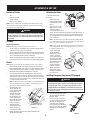 5
5
-
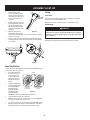 6
6
-
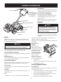 7
7
-
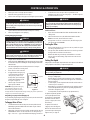 8
8
-
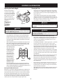 9
9
-
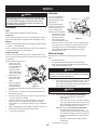 10
10
-
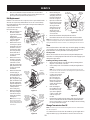 11
11
-
 12
12
-
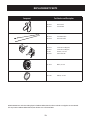 13
13
-
 14
14
-
 15
15
-
 16
16
-
 17
17
-
 18
18
-
 19
19
-
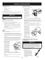 20
20
-
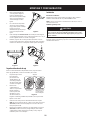 21
21
-
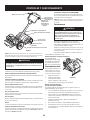 22
22
-
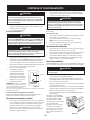 23
23
-
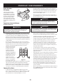 24
24
-
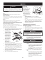 25
25
-
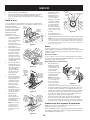 26
26
-
 27
27
-
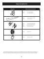 28
28
-
 29
29
-
 30
30
-
 31
31
-
 32
32


Cub Cadet 21AA40M8710 Manual de usuario
- Categoría
- Mini cultivadores
- Tipo
- Manual de usuario
- Este manual también es adecuado para
En otros idiomas
- English: Cub Cadet 21AA40M8710 User manual
Documentos relacionados
-
Cub Cadet 21AA40M8710 Manual de usuario
-
-
-
Cub Cadet CC30 E Manual de usuario
-
-
-
-
Otros documentos
-
Craftsman CMXGVAM1144037 El manual del propietario
-
Troy-Bilt 21D655A766 Manual de usuario
-
Troy-Bilt 21D64M8711 Manual de usuario
-
 Remington Power Tools 109312-01 Manual de usuario
-
Remington Garden Wizard 109312-01 El manual del propietario
-
-
