A SYSTEMS DM434 Manual de usuario
- Categoría
- Equipo de música suplementario
- Tipo
- Manual de usuario

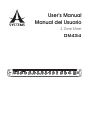
User’s Manual
Manual del Usuario
4 Zone Mixer
DM434

2
DM434
English
INTRODUCTION �������������������������������������������������������������������������������������������������������������������������� 4
FEATURES ����������������������������������������������������������������������������������������������������������������������������������� 4
INSTALLATION ���������������������������������������������������������������������������������������������������������������������������� 4
FRONT PANEL DESCRIPTION ��������������������������������������������������������������������������������������������������� 5
REAR PANEL DESCRIPTION������������������������������������������������������������������������������������������������������ 6
SPECIFICATIONS ������������������������������������������������������������������������������������������������������������������������ 7
INTRODUCCIÓN ��������������������������������������������������������������������������������������������������������������������������9
CARACTERÍSTICAS �������������������������������������������������������������������������������������������������������������������� 9
INSTALACION ������������������������������������������������������������������������������������������������������������������������������ 9
DESCRIPCIÓN DEL PANEL FRONTAL �������������������������������������������������������������������������������������10
DESCRIPCIÓN DEL PANEL POSTERIOR ��������������������������������������������������������������������������������10
ESPECIFICACIONES ����������������������������������������������������������������������������������������������������������������12
DIMENSIONS / DIMENSIONES ����������������������������������������������������������������������������������������������� 13
APPLICATION / APLICACIONES ��������������������������������������������������������������������������������������������� 14
Asystems reserves the right to alter information provided in this document without prior notice�
Asystems se reserva el derecho de mejorar o alterar cualquier información provista dentro de este documento sin previo aviso�
V1�2 09/27/2017
CONTENTS
CONTENIDO
APPENDIX

3
DM434
English
1. Read these instructions before operating this
apparatus.
2. Keep these instructions for future reference.
3. Heed all warnings to ensure safe operation.
4. Follow all instructions provided in this document.
5. Do not use this apparatus near water or in locations
where condensation may occur.
6. Clean only with dry cloth. Do not use aerosol or liquid
cleaners. Unplug this apparatus before cleaning.
7. Do not block any of the ventilation openings. Install
in accordance with the manufacturer
’
s instructions.
8. Do not install near any heat sources such as radiators,
heat registers, stoves, or other apparatus (including
.
9. Do not defeat the safety purpose of the polarized or
grounding-type plug. A polarized plug has two blades
with one wider than the other. A grounding type plug
has two blades and a third grounding prong. The wide
blade or the third prong is provided for your safety. If
the provided plug does not into your outlet, consult
an electrician for replacement of the obsolete outlet.
10. Protect the power cord from being walked on or
pinched particularly at plug, convenience receptacles,
and the point where they exit from the apparatus.
11. Only use attachments/accessories by the
manufacturer.
12. Use only with a cart, stand, tripod, bracket, or
table by the manufacturer, or sold with
the apparatus. When a cart is used, use caution
when moving the cart/apparatus
combination to avoid injury from tip-
over.
13. Unplug this apparatus during lighting
storms or when unused for long
periods of time.
14. Refer all servicing to service personnel.
Servicing is required when the apparatus has been
damaged in any way, such as power-supply cord or
plug is damaged, liquid has been spilled or objects
have fallen into the apparatus, the apparatus has
been exposed to rain or moisture, does not operate
normally, or has been dropped.
IMPORTANT SAFETY INSTRUCTIONS
CAUTION: TO REDUCE THE RISK OF ELECTRIC SHOCK,
DO NOT REMOVE COVER (OR BACK)
NO USER SERVICEABLE PARTS INSIDE
REFER SERVICING TO QUALIFIED PERSONNEL
The lightning flash with arrowhead symbol, within an
equilateral triangle, is intended to alert the user to the
presence of uninsulated
“
dangerous voltage
”
within the
product
’
magnitude to constitute a risk of electric shock to persons.
The exclamation point within an equilateral triangle is in-
tended to alert the user to the presence of important operat-
ing and maintenance (servicing) instructions in the literature
accompanying the appliance.
WARNING: To reduce the risk of or electric shock, do
not expose this apparatus to rain or moisture.
CAUTION: Use of controls or
adjustments or performance
of procedures other than those may result in
hazardous radiation exposure.
The apparatus shall not be exposed to dripping or splashingand that no objects with liquids, such as vases,
shall be placed on the apparatus. The MAINS plug is used as thedisconnect device,the disconnect device shall
remain readily operable.
Warning: the user shall not place this apparatus in the area during theoperation so that the mains switch
can be easily accessible.
CAUTION
RISK OF ELECTRIC SHOCK
DO NOT OPEN

4
DM434
English
INTRODUCTION
Congratulations on your purchase of the DM434 four-zone
mixer that is ideal for use in all manners of installations,
in such venues as hotels, convention centers, theatres,
restaurants and retail outlets. The DM434 oers three
stereo line inputs, on paging microphone input with EQ
and ducking depth, and an emergency input� Four zone
outputs provide maximum zone separation and a mono
“utility” output is also included for such areas as restrooms
and foyers� Zone and utility outputs all have individual
source selectors and level controls, while the rst two
zones are selectable as stereo/mono� An emergency
interface connector allows for an override control and
insert of emergency message paging� The added option
of remote volume control for each zone makes the DM
mixers a must-have for your zone mixing requirements�
FEATURES
• Three unbalanced line-level stereo RCA inputs with
individual trim controls
• Four balanced zone outputs with independent source
select switches and level controls
• Balanced XLR paging microphone and 3-pin phoenix
euroblock emergency microphone inputs
• Microphone ducking depth and EQ controls
• Balanced 3-pin phoenix/euroblock utility output provides
audio to general utility areas (foyers, restrooms, etc)
• Remote level controls can be wired to all four zones
• Utility output source selectable
• Stereo/mono switch on zones 1 and 2
• Optional acessory: RM-2 wall-mount rotary controls
INSTALLATION
Rack Mounting
The Asystems DM434 zone mixers are standard 1U
rack mountable mixers� An additional 4” of depth are
needed behind the mixer to allow room for the back panel
connectors� To avoid overheating, be sure that there is
enough ventilation space around the unit for cooling� Do
not place the mixer in contact with, or directly on top of,
high temperature devices such as power ampliers.
Connectors
DM434 zone mixers use balanced XLR jacks for paging
microphone input, unbalanced stereo RCA jacks for
music input, and balanced 3-pin phonix/euroblock jacks
for emergency audio, zone output and utility output� RJ-
45 jacks provide input and output for paging and remote
level control, while an RS-232 D-type 9-pin connector is
provided for source link�
Impedance
The microphone input impedance is less than 2k ohms�
The outputs of the DM434 are electronically balanced with
output impedance lower than 120 ohms� When driving
transformer coupled loads, it may be necessary to create
600 ohm source impedances� For this purpose, install two
247 ohm resistors in series with pin 2 and 3�
Mains Connection
The DM434 uses a standard IEC receptacle and a
universal mains cable to make the AC mains connection�
Make sure all units in the sound system are correctly
grounded� For your own safety, do not remove the ground
connection within the units or on the supplied cable, or
fail to make this connection at all� The audio ground is
capacitor decoupled so please isolate it from the power
ground� Do not attempt to solve ground loop problems by
disconnecting the power ground�
Safety Fuse Replacement
A safety fuse protects the unit from serious malfunction�
The fuse will blow in the event of power problems or
short circuits� If this happens, please replace it with an
identical fuse only� If the new fuse also blows right after
replacement, it is likely there is a problem with the unit�
In that event, please contact Asystems for assistance in
getting the unit repaired� Never use fuses that are not
rated for the unit. This may cause re or electric shocks.

5
DM434
English
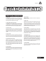
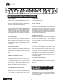
FRONT PANEL DESCRIPTION
1. Mid Control
The MID EQ is set at 800Hz with +/-15 dB of boost or
cut available� Adjust this knob clockwise to add fullness
to the microphone� Adjust the knob clockwise to reduce
excessively hard or ‘telephone-like’ sounds�
2. Treble (High Frequency) Control
The TREBLE control’s center frequency is set at 8 kHz with
+/-15 dB of boost or cut available. Adjust this knob clockwise
to add crispness or clarity to the microphone� Adjust the
knob counterclockwise to reduce hissing or sibilance�
3. Volume Control
This knob controls the level of the balanced microphone
input that is fed to each zone (and utility when MIC is
selected) the output range is set from -∞ to “MAX” (about
+55 dB). Turn the knob clockwise to boost the microphone
volume�
4. Depth Control
Turning this knob clockwise will gradually decrease the
zone music source output and change the paging depth to
make the microphone output louder than the music source�
5. Zone Volume/Level Control
Adjust this control to set the level of audio that is sent to
each zone. The gain range is -∞ to “MAX” (about +20dB).
Turn the knob clockwise to increase the volume level
and counterclockwise to decrease the level� This control
does not aect the actual level of the music input to the
mixer; rather it adjust the output level that is sent to the
corresponding zone�
6. Source Switch
This switch allows you to select one of three audio sources
to be sent to the zone output. A signal source must rst be
connected to the input on the back panel (see “SOURCE
INPUT” section)�
7. Mono Button
When this button is pressed, the L&R zone outputs are
summed to mono�
8. Utility Level
Adjust this control to set the level of audio that is sent to the
utility zone. The gain range is -∞ to “MAX” (about +20dB).
Turn the knob clockwise to increase the volume level and
counterclockwise to decrease the level� This control does
not aect the actual level of the audio inputs, rather it simply
adjusts the level sent to the utility zone�
9. Source Button
This switch allows you to select the source of the utility
output connector� You are able to choose from one of
the three line inputs and the microphone input� A signal
source must rst be connected to the appropriate input
on the back panel (see “SOURCE INPUT” and “PAGING
MICROPHONE” sections)�
10. Emergency Trim
The TRIM knob adjusts the level of the emergency audio
input� When the 24VDC control circuit is activated by an
external device the red LED light illuminates and all zone
and utility source outputs are replaced by the emergency
audio input� If the 24V DC control circuit is activated but
there is no emergency audio input, the emergency audio
input source will be the paging microphone�
11. Power Switch
This switch turns the power for the mixer on and o. The
unit must be connected to an appropriate AC mains power
supply to be turned on�
123 4 5 7 6 8 9 10 11

6
DM434
English
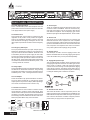
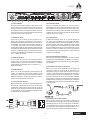
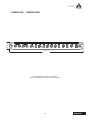
REAR PANEL DESCRIPTION
12. Power Cable Receptacle
This is a standard IEC power cable receptacle� Plus the
power cable in here and connect the other end of the cable
to an appropriate AC mains power supply�
13. 24V DC Control
This terminal black input accepts an external 24V DC
regardless of the position of the positive and negative
poles� It will activate the emergency function, which will
route the external emergency message to all zone and
utility outputs� It provides an override control for emergency
use�
14. Emergency Audio Input
The 3-pin phoenix/euroblock input jack accepts input by
balanced or unbalanced connections� This input works in
conjunction with the 24V DC CONTROL� When the circuit
is activated by the 24V DC power supply all other audio
input sources will be terminated� The source connected to
this emergency audio input will be routed to all zones and
the utility output� The grounding and positive and negative
connections should be wired as indicated by the G, + and
– markings below the connector�
15. Utility Output
This is a standard line-level 3-pin phoenix/euroblock output
for balanced or unbalanced connections� The grounding
and positive and negative connections should be wired as
indicated by the G, + and – markings below the connector�
16. Zone Outputs
These are standard 3-pin phoenix/euroblock connectors�
The zone outputs include left (L) and right (R) channel
outputs (zone 4 only has mono output)� When operating in
mono mode, use the left channel’s connector only�
17. Remote Level Control
This socket allows for the connection of external volume
control devices to remotely control audio outputs� Each
remote socket controls up to two zones� When the REMOTE
connection is not made, the output level of each zone will
be according to the level selected on the face of the mixer�
Wire the Asystems RM-2 rotary control as follows�
18. Source Input
These are unbalanced line-level stereo RCA inputs� There
are three in total on the DM434� These are most commonly
used with music players such as CD players, MP3 players
and notebook computers� The accompanying gain control
allows the input signal to be adjusted between -10 and +20 dB.
19. Source Link
The source link is an RS-232 D-type 9-pin connector that
distributes the three source inputs to the next compatible
zone mixer in the series� It also functions to receive the source
input from other DM434 zone mixers� This function allows the
source input from one Asystems zone mixer to be used for
many other systems while simplifying wiring schemes�
20. Paging Control
The RJ-45 jack is used to connect a paging control to the
DM434� The DM434 does not including a paging microphone/
control as standard� They can be purchased separately�
21. Paging Microphone Input
This is a balanced XLR jack that is used to connect the output
of a paging microphone to the mixer� It includes a gain control
with a range of -15dB to +15dB. The paging microphone
connects to the mixer through an XLR input and the paging
control RJ-45 connector� The paging control allows users to
select the destination of the microphones signal� The following
is a diagram detailing how to make the connection�
22. Phantom Power Switch
This switch will activate +15V DC of phantom power on the
paging microphone input� This makes the input suitable for use
with condenser microphones� Please check your microphone’s
user manual for information on whether it requires phantom
power before you apply it to the microphone input�
12 13 14 15 1617 18 19 20
21
22
V1
CV1
V2
CV2
GND
GND
RM-2 REMOT
ER
EMOTE LEVEL CONTROL SOCKET

7
DM434
English
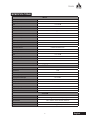
SPECIFICATIONS
INPUT
Microphone
Input Impedance 2kΩ
Gain -∞ to +55 dB
Frequency Response 40Hz to 20 kHz, ±0.5 dB
EIN -128 dBu
CMRR 100 dB @ Max Gain
Phantom Power +15V DC
Input Connectors Balanced XLR
Stereo BGM Input
Input Impedance 40kΩ
Gain -∞ to +20 dB
Frequency Response 40Hz to 20 kHz, ±0.5 dB
Input Connectors Unbalanced Stereo RCA
Emergency Audio
Input Impedance 14kΩ
Gain -∞ to +10 dB
Frequency Response 50Hz to 20kHz, ±0.5 dB
Input Connectors 3-pin phoenix/euroblock
Panic Override +24V DC
Input Connectors 24V DC terminal
OUTPUT
Stereo Zone Output
Impedance 120Ω
Gain -10 to +20 dB
Frequency Response 40Hz to 20kHz, ±0.5 dB
Paging Override Depth Cut +10 dB
Output Connectors 3-pin phoenix/euroblock
Utility Output
Impedance 120Ω
Frequency Response 40Hz to 20kHz, ±0.5 dB
Gain -10 to +20 dB
Output Connectors 3-pin phoenix/euroblock
SYSTEM
THD <0�2%
Crosstalk -75 dB @ 1 kHz between any 2 outputs
Mains Power 100 to 120VAC, 200 to 240VAC, 50/60 Hz
Size (W x H x D) 483 x 44 x 173 mm (19” x 1�73” x 6�8”)
Weight 2�5 kg (5�5 lbs)

8
DM434
Español

9
DM434
Español
INTRODUCCION
Le damos la enhorabuena, por su compra de la
mezcladora de 4 zonas DM434, que es ideal para ser
utilizada en todo tipo de lugares; como hoteles, centros
de convenciones, teatros, restaurantes y puntos de
venta� La DM434 Ofrece tres entradas de línea estéreo,
una entrada para micrófono de aviso público (paging)
con EQ y una función ducking (atenuador) y, una entrada
de emergencia� Las salidas de cuatro zonas otorgan
una máxima separación de zona, y una salida mono
“utility /utilidad”, también se incluye para estancias como
baños y vestíbulos� Las salidas de zone y utility, todas
tienen selectores individuales de señal y controles de
nivel; las primeras dos zonas son seleccionables como
estéreo/mono� Un conector de interface de emergencia,
permite tomar el control sobre el sistema y sobre el insert/
puerto, para avisos de emergencia� La opción adicional
de control remoto de volumen para cada zona, hace que
la mezcladora DM sea esencial para sus requisitos de
mezcla de zona�
CARACTERISTICAS
• Tres entradas de nivel de línea estéreo RCA con
controles de trim individuales
• Cuatro salidas de zona balanceadas, con selectores de
fuente independiente y controles de nivel
• Micrófono balanceado XLR para anuncios y entradas
de emergencia de micrófono 3-pin phoenix/Euroblock
• Función Ducking para micrófono y controles de EQ
• Salida “Utility” balanceada de 3-pines Phoenix/
Euroblock, que provee audio a las áreas de servicio
(como vestíbulos, baños, etc�)
• Fuente de salida “Utility” seleccionable
• Selector estéreo/mono en zona 1 y 2
INSTALACION
Montaje en Rack
Las mezcladoras DM434 de Asystems, son mezcladoras
montables en rack estándar 1U� Se necesita una
distancia adicional de 4” detrás de la mezcladora, para
dejar un espacio para las conexiones del panel posterior�
Para evitar sobrecalentamientos, asegúrese de que
hay suciente espacio de ventilación alrededor de la
unidad para el enfriamiento� No coloque la mezcladora
directamente encima de dispositivos que generen altas
temperaturas como los amplicadores de potencia.
Conectores
Las mezcladoras de zona DM434 utilizan; conectores de
entrada balanceadas de micrófono XLR para “Paging”,
entradas RCA estéreo desbalanceadas para entradas de
música y un conector de audífono balanceada de 3-pines
phoenix/euroblock para entrada de audio de emergencia,
salida de zona y salida de “Utility”� Los conectores de
RJ45 otorgan una entrada y una salida, para la función
“Paging” y el control remoto del nivel, también está
integrado un conector RS-232 tipo-D de 9-pines para
enlace de fuente�
Impedancia
La impedancia de entrada del micrófono es menor que
2k ohmios� Las salidas del DM434 están balanceadas
electrónicamente con impedancia de salida menor a los 120
ohmios� Cuando se manejan cargas de transformadores
acopladas, es necesario crear una fuente de impedancia
de 600 ohmios� Para este propósito, instale dos resistores
de 247 ohmios en serie con 2 y 3 pines�
Conexiones Principales
El DM434 utiliza un receptáculo IEC estándar y un
cable principal universal para efectuar las conexiones
principales de AC� Asegúrese de que todas las unidades
en la instalación audio estén bien conectadas a tierra�
Para su propia seguridad, no remueva la conexión a
tierra dentro de la unidad o en el cable de alimentación,
o intente no hacer esta conexión de cualquier modo� La
puesta a tierra del audio es un capacitor desacoplado,
así que por favor aíslelo de la puesta a tierra� No intente
solucionar problemas eventuales desconectando de la
puesta a tierra�
Reemplazo del Fusible de Seguridad
Un fusible de seguridad protege la unidad de ser
dañada por mal uso� Este fusible se fundirá en caso de
problemas de energía o cortocircuitos� Si esto sucede,
por favor reemplácelo solamente con un fusible idéntico�
Si el nuevo fusible también se funde después de haberlo
reemplazarlo, es probable que exista un problema con
la unidad� En ese caso, por favor contáctese con su
distribuidor de Asystems más cercano, para servicio
o reparaciones� Nunca utilice fusibles que no estén
adaptados a la unidad� Esto puede causar fuego o
descargas eléctricas�

10
DM434
Español
1. Control de Medio
El EQ de Medios está preestablecido a 800 Hz con +/-15
dB de aumento o recorte. Ajuste esta perilla de control en
sentido de las agujas de un reloj para añadir riqueza a los
micrófonos� Ajuste la perilla de control en sentido inverso,
para reducir sonidos excesivamente intensos�
2. Control de Agudo (Frecuencia Alta)
La frecuencia central de control de AGUDO/TREBLE está
preestablecido a 8 kHz con +/-15 dB de aumento o recorte.
Ajuste esta perilla de control en el sentido de las agujas
de un reloj para añadir nitidez y claridad a los micrófonos�
Ajuste la perilla de control en el sentido inverso para reducir
el silbido u otros ruidos de alta frecuencia�
3. Control de Volumen
Esta perilla de control, controla el nivel de la entrada de un
micrófono balanceado que es alimentada en cada zona (y
a Utility cuando MIC es seleccionado)� El rango de salida
es de +15 dB hasta +55 dB. Gira la perilla de control en el
sentido de las agujas de un reloj para reforzar el volumen
del micrófono�
4. Control de Profundidad
Moviendo esta perilla de control, en el sentido de las
agujas de un reloj, ara que se reduzca gradualmente la
señal de salida de la fuente de música de zona y cambiara
la profundidad de voceo (paging) para hacer que la señal
del micrófono sea más fuerte que la señal de salida de la
música�
5. Volumen de Zona/Control de Nivel
Ajuste este control para establecer el nivel de audio que
esta enviada en cada zona. El rango de aumento es de -∞
a “MAX” (próximamente +20 dB). Mueva la perilla de control
en el sentido de las agujas de un reloj, para aumentar el
nivel del volumen y en sentido inverso para disminuir el
nivel� Este control no afecta el nivel actual de la señal de
entrada en la mezcladora, sino que ajusta el nivel de la
señal que esta enviada a una zona en particular�
6. Interruptor de Fuente / Source Switch
Este interruptor le permite seleccionar una de las tres
fuentes de audio que son enviadas a la zona de salida/zone
output� Una fuente de señal debe primero ser conectada,
en una entrada en el panel posterior� (Vea la sección
“ENTRADA DE FUENTE”)�
7. Botón Mono
Cuando se presiona el botón MONO, las salidas de zona
L & R son juntadas a mono�
8. Nivel de UTILITY
Ajuste este control para ajustar el nivel del audio que es
enviado a la zona de utilidad/ Utility Zone� El aumento es de
-10 dB a +20 dB. Gire la perilla de control en el sentido de
las agujas de un reloj para aumentar el nivel del volumen�
Gire la perilla de control en sentido inverso para reducir el
nivel del volumen� Este control no afecta al nivel actual de
la entrada del audio en la mezcladora� Solo ajusta el nivel
enviado a la zona de utilidad/ Utility�
9. Botón Fuente (Source)
Este interruptor le permite seleccionar la señal de la fuente
del conector Utility� Puede elegir una de las tres entradas
de línea y la entrada del micrófono� Primero se debe
conectar una fuente de señal en el panel posterior� (Vea
las secciones “ENTRADA DE FUENTE” y “MICRÓFONO
DE PAGING”)�
10. Trim de Emergencia
La perilla de control TRIM, ajusta el nivel de la entrada
del audio de emergencia� Cuando el circuito de control
de 24 VDC está activado por un dispositivo externo; la luz
LED roja se ilumina, y entonces las salidas de zona y las
salidas Utility Source, son substituidas por la entrada de
audio de emergencia� Si el circuito de control de 24 VDC
está activado pero no hay entrada de audio de emergencia,
la fuente de entrada de audio de emergencia será el
micrófono de paging�
11. Conmutador de Alimentación
Este interruptor enciende y apaga la alimentación para la
mezcladora� El LED verde se ilumina cuando la mezcladora
está conectada con una fuente de alimentación principal
activa AC�
DESCRIPCION DEL PANEL
TRASERO
12. Receptáculo del Cable de Energía
Este es un receptáculo para un cable de energía IEC
estándar� Conecte el cable de voltaje con este receptáculo
y conecte el otro extremo a una fuente de alimentación
principal AC apropiada�
123 4 5 7 6 8 9 10 11
DESCRIPCION DEL PANEL FRONTAL

11
DM434
Español
13. Control 24VDC
Este terminal de entrada, acepta un voltaje externo de 24
VDC sin que importe la posición de los polos negativos o
positivos� Activará la función de emergencia, que enviara
el mensaje de emergencia a todas las salidas y todas las
zonas� Proporciona un control prioritario de desactivación
(Override) para usos de emergencia�
14. Entrada de Audio
Este conector de entrada phoenix/euroblock de 3
pines acepta entradas de conexiones balanceadas o
desbalanceadas� Dicha entrada funciona en conjunto con
el CONTROL 24V� Cuando el circuito está activado por
un suministro de potencia 24V DC todas las fuentes de
entrada audio pueden ser interrumpidas, la fuente de audio
conectada al audio de emergencia que será llevada a todas
las zonas y salidas de Utility� Las conexiones positivas y
negativas de tierra deben ser cableadas como lo indicado,
el + y – debajo del conector�
15. Salida de Utilidad
Es una salida de nivel de línea estándar phoenix/
euroblock de 3 pines para conexiones balanceadas o
desbalanceadas� Las conexiones positivas y negativas
de tierra deben ser cableadas como lo indicado, el + y –
debajo del conector�
16. Salidas de Zona
Estos son conectores estándar phoenix/euroblock de
3 pines� Las salidas de zona incluyen salidas de canal
izquierdo (L) y derecho (R) (la zona 4 solamente tiene una
salida de canal mono)� Al operar en modo mono, utilice el
conector del canal izquierdo únicamente�
17. Control de Nivel Remoto
Este puerto conector, permite la conexión de dispositivos
de control de volumen externos para controlar la música
remotamente� Cada puerto conector permite el controla
hasta dos zonas� Cuando la conexión remota / REMOTE
no está utilizada, el nivel de salida para cada zona será
el seleccionado en la mezcladora�
18. Fuente de Entrada
Estas son entradas RCA estéreo de nivel de línea no
balanceadas� Hay tres en total en la DM434� Estas son los
más utilizadas con los reproductores de música, tales como
reproductores de CD, reproductores de MP3 y ordenadores
portátiles� El control de nivel de la señal de entrada permite
un ajuste entre -10 y +20 dB.
19. Link de Fuente
El Enlace de fuente de señal, es un conector RS-232 de
tipo-D de 9-pines, que distribuye las tres entradas de fuente,
a la siguiente mezcladora de zona compatible en la serie�
También funciona para recibir entradas de fuentes desde
otras mezcladoras de zona DM434� Esta función permite
que las entradas de fuente de una mezcladora de zona de
Asystems, pueda ser utilizada para varios otros sistemas
de mezcladoras de zona, simplicando al mismo tiempo la
instalación del cableado�
20. Control de Paginación (Paging)
Este conector RJ45 esta utilizado para conectar el control
de paging a mezcladora DM434� El DM434 no incluye un
micrófono de paginación / Control de serie� Se pueden adquirir
por separado�
21. Entrada de micrófono de paginación
Este es un conector XLR equilibrado que se utiliza para
conectar la salida de un micrófono de paginación a la
mezcladora� Incluye un control de aumento con un rango de
-15 dB a + 15 dB. El micrófono de paginación se conecta a la
mesa de mezclas, a través de una entrada XLR y un conector
de control de paginación RJ-45� El control de búsqueda/
paging control permite a los usuarios seleccionar el destino
de la señal de los micrófonos� A continuación hay un diagrama
que detalla cómo hacer para que el suministro de la conexión
se pueda activar�
22. Interruptor de Fuente Fantasma
Este interruptor activará +15V de fuente fantasma en la
entrada de micrófono de paging, de forma que la entrada sea
adecuada para el uso con los micrófonos de condensador�
Le aconsejamos que consulte el manual del usuario de su
micrófono, para informarse si requiere fuente fantasma o no,
antes de que usted la aplique a la entrada del micrófono�
12 13 14 15 1617 18 19 20
21
22
V1
CV1
V2
CV2
GND
GND
RM-2 REMOT
ER
EMOTE LEVEL CONTROL SOCKET

12
DM434
Español
ESPECIFICACIONES
ENTRADA
Micrófono
Impedancia de Entrada 2 Kohm
Gain -∞ a 55 dB
Respuesta de Frecuencia 40 Hz a 20 kHz, ± 0.5 dB
EIN -128 dBu
CMRR 100 dB @ Máximo Aumento
Phantom Power + 15V DC
Conectores de Entrada XLR Balanceado
Stereo Input BGM
Impedancia de Entrada 40kΩ
Gain -∞ a 20 dB
Respuesta de Frecuencia 0 Hz a 20 kHz, ± 0.5 dB
Conectores de Entrada Estéreo RCA No Balanceado
Audio de Emergencia
Impedancia de Entrada 14kΩ
Gain -∞ a 10 dB
Respuesta de Frecuencia 50 Hz a 20 kHz, ± 0.5 dB
Conectores de Entrada phoenix / euroblock de 3-pines
Anulación de Urgencias +24V DC
Conectores de Entrada Terminal de 24V DC
SALIDA
Salida de Zona Estéreo
Impedancia 120Ω
Gain -10 A 20 dB
Respuesta de Frecuencia 40 Hz a 20 kHz, ± 0.5 dB
Paging Override Depth Corte de +10 dB
Conectores de Salida phoenix / euroblock de 3-pines
Salida de Utilidad/Utility
Impedancia 120Ω
Respuesta de Frecuencia 40 Hz a 20 kHz, ± 0.5 dB
Gain -10 a 20 dB
Conectores de Salida phoenix / euroblock de 3-pines
SISTEMA
THD <0,2%
Crosstalk -75 DB @ 1 kHz entre cualesquiera de 2 salidas
Suministro Eléctrico 100 a 120 VCA, 200 a 240 VCA, 50/60 Hz
Dimensiones (W x H x D) 483 x 44 x 173 mm (19” x 1�73” x 6�8”)
peso 2�5 kg (5�5 lbs)

13
DM434
Appendix
DIMENSIONS DIMENSIONES
All measurements are shown in mm/inches�
Todas las medidas están mostradas en mm/pulgadas�
44 mm / 1.7”
437 mm / 17.2”

14
DM434
Appendix
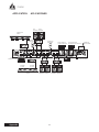
APPLICATION
APLICACIONES
RESTROOMS
BAÑOS
SPEAKER
ALTAVOZ
SPEAKER
ALTAVOZ
SPEAKER
ALTAVOZ
SPEAKER
ALTAVOZ
AUDIO CASSETTE
CASSETTE DE AUDIO
CD/LD/VCR PLAYER
REPRODUCTO DE CD/LD/VCR
PAGING MIC
MIC DE PAGIN
G
TO NEXT DM434
A SIGUIENTE DM434
OFFICE
OFICINA
AMP
AMP
AMP
AMP
AMP
EQ
EQ EQ
ATTENUATOR
ATENUADOR
ATTENUA TOR
ATENUADOR
LEFT
IZQUIERDO
RIGHT
DERECHO
LEFT
IZQUIERDO
RIGHT
DERECHO
LEFT
IZQUIERDO
RIGHT
DERECHO
AM/FM TUNER
ALARM SYSTEM
SISTEM
A DE ALARMA

15
DM434
Appendix
NOTES

www�asystems-sys�com
-
 1
1
-
 2
2
-
 3
3
-
 4
4
-
 5
5
-
 6
6
-
 7
7
-
 8
8
-
 9
9
-
 10
10
-
 11
11
-
 12
12
-
 13
13
-
 14
14
-
 15
15
-
 16
16


A SYSTEMS DM434 Manual de usuario
- Categoría
- Equipo de música suplementario
- Tipo
- Manual de usuario
En otros idiomas
- English: A SYSTEMS DM434 User manual
Otros documentos
-
Cloud CX462 Ficha de datos
-
Ecler MIMO54 Manual de usuario
-
Rane ZONETECH Guía de inicio rápido
-
Behringer EUROCOM MA4000M Guía de inicio rápido
-
-
-
-
-
Bose ControlSpace AMS-8 Safety Instructions & Installation Manual