Extraflame Kit Wireless thermostat El manual del propietario
- Categoría
- Componentes del dispositivo de seguridad
- Tipo
- El manual del propietario

GUIDA TERMOSTATO WIRELESS E RICEVITORE
WIRELESS THERMOSTAT AND RECEIVER GUIDE
GUIDE THERMOSTAT SANS FIL ET RÉCEPTEUR
BEDIENUNGSANLEITUNG WIRELESS-THERMOSTAT UND EMPFÄNGER
GUÍA TERMOSTATO WIRELESS Y RECEPTOR
004276508 - Rev.007

2

3
L'accessorio inibisce il funzionamento del telecomando.
The accessory inhibits the remote control operation.
L'accessoire empêche le fonctionnement de la télécommande.
Das Zubehör spert den Betrieb der Fernbedienung.
El accesorio inhibe el funcionamiento del mando a distancia.
ITALIANO 4
ENGLISH 17
FRANÇAIS 30
DEUTSCH 43
ESPAÑOL 56

4
POSIZIONAMENTO RICEVITORE E TERMOSTATO
Il ricevitore non deve essere posizionato sui anchi o parti calde della stufa! Si consiglia il montaggio a parete, lontano
da fonti di calore.
MONTAGGIO TERMOSTATO
TX RX
| 1
SERIAL
O.C.
12VDC
RECEIVER
| 2
TX RX
| 1
SERIAL
O.C.
12VDC
RECEIVER
| 2
TX RX
| 1
SERIAL
O.C.
12VDC
RECEIVER
| 2
TX RX
| 1
SERIAL
O.C.
12VDC
RECEIVER
| 2
TX RX
| 1
SERIAL
O.C.
12VDC
RECEIVER
| 2
TX RX
| 1
SERIAL
O.C.
12VDC
RECEIVER
| 2
1mt
1mt
1.5 mt
1. Forare, inserire sher e
ssare supporto con viti.
2. Applicare ricevitore/
termostato sul supporto
3. Ruotare ricevitore/termostato sul supporto
no al suo bloccaggio.
Il termostato può essere tenuto
in appoggio nella zona da
termostatare o essere montato
su una parete interna. Nel caso di
montaggio a parete, si consiglia di
tenere le distanze ragurate.
MONTAGGIO A PARETE

5
COLLEGAMENTO RICEVITORE
Non è neccessaria alcuna congurazione.
*con supporto a muro 31mm
TX RX
| 1
SERIAL
O.C.
12VDC
RECEIVER
| 2
+
I
REAR
Batterie 3x AAA
BATTERIE TERMOSTATO
cavo seriale
Open
Ingresso seriale
stufa a pellet
Nota: il
collegamento a
onde convogliate
deve essere
eseguito da un
tecnico qualicato.
SPECIFICHE TECNICHE
Dimensioni (L x P x H) 80x80x27 mm* Umidità relativa massima (senza condensa) 95%
Grado di protezione IP21 Gamma di misurazione temperatura 0 °C / 99 °C
Alimentazione termostato 3 battrie AAA Precisione lettura temperatura + - 0,5 °C
Alimentazione ricevitore 12Vdc Precisione lettura umidità 5%
Temperatura di funzionamento 0°C / + 50 °C Contatto relè (ricevitore e termostato) 5A 30 VDC
Temperatura di immagazzinamento -10°C / +70°C Portata/ frequenza RF
~20mt/ 868MHz
Banda di frequenza 868,3 MHZ Massima potenza trasmessa 4 mW ERP
Banda di frequenza 869,85MHZ Massima potenza trasmessa 4 mW ERP

6
CONESSIONI RICEVITORE
1. Ingresso cavo seriale (SERIAL)
2. Ingresso collegamento onde convogliate O.C.
3. Ingresso alimentazione 12VDC
4. Contatto relè ( )
5. Non utilizzato (I1 - I2)
6. Tasto Reset
TX RX
| 1
SERIAL
O.C.
12VDC
RECEIVER
| 2
+
I
1
2
3
4
5
6
TX RX
| 1
SERIAL
O.C.
12VDC
RECEIVER
| 2
+
I

7
TX
| 1
SERIAL
O.C.
12VDC
GSM
RX
| 2
SIM CARD
TX RX
| 1
SERIAL
O.C.
12VDC
RECEIVER
| 2
TX
| 1
SERIAL
O.C.
12VDC
WI-FI
RX
| 2
INTERNET
ACCESS POINT
REMOTE SERVER
TX RX
| 1
SERIAL
O.C.
12VDC
RECEIVER
| 2
+
I
TX
| 1
SERIAL
O.C.
12VDC
GSM
RX
| 2
SIM CARD
TX RX
| 1
SERIAL
O.C.
12VDC
RECEIVER
| 2
TX
| 1
SERIAL
O.C.
12VDC
WI-FI
RX
| 2
INTERNET
ACCESS POINT
REMOTE SERVER
TX
| 1
SERIAL
O.C.
12VDC
GSM
RX
| 2
SIM CARD
TX RX
| 1
SERIAL
O.C.
12VDC
RECEIVER
| 2
TX
| 1
SERIAL
O.C.
12VDC
WI-FI
RX
| 2
INTERNET
ACCESS POINT
REMOTE SERVER
I termostati devono essere abbinati al ricevitore radio che sarà collegato alla stufa tramite cavo a onde
convogliate o Seriale. E’ possibile associare al massimo 3 termostati esterni.
Un esempio illustrato:
INSTALLAZIONE TERMOSTATO
cavo seriale
Termostato 1
Termostato 2
(canalizzazione)
Termostato 3
(canalizzazione)

8
RICEVITORE LED
1
Led verde - Indica la presenza di tensione:
- Spento : Alimentazione assente
- Acceso sso : alimentazione presente
2
Led giallo - Indica la presenza di comunicazione radio:
- Spento : comunicazione radio assente
- Lampeggiante : comunicazione presente
3
Led rosso - Indica lo stato del contatto ausiliario :
- Spento : Contatto aperto
- Acceso sso : Contatto chiuso
4 - 5
Led gialli - Indica la trasmissione con la scheda:
- Spenti, lampeggianti entrambi o lampeggiante solo 1 :
n
essuna trasmissione con la scheda elettronica.
- Lampeggianti entrambi ad intermittenza :
comunicazione corretta con la scheda.
TX RX
| 1
SERIAL
O.C.
12VDC
RECEIVER
| 2
+
I
321 4 5

9
TERMOSTATO TASTI
1
- Pressione breve : Esce dalla modoalità SLEEP.
- Pressione lunga : ON/OFF stufa.
2
- Pressione breve : Accesso nel set termostato per
incrementare la temperatura.
3
- Pressione breve : Decrementa set potenza stufa.
4
- Pressione breve : Incrementa set potenza stufa.
5
- Pressione breve : Accesso nel set termostato per
decrementare la temperatura
1+5
- Pressione lunga :
Accesso nel menu IMPOSTAZIONI del termostato.
1+2
- Pressione lunga :
abilita/disabilita funzione economia (NO IDRO)
TX
| 1
SERIAL
O.C.
12VDC
GSM
RX
| 2
SIM CARD
TX RX
| 1
SERIAL
O.C.
12VDC
RECEIVER
| 2
TX
| 1
SERIAL
O.C.
12VDC
WI-FI
RX
| 2
INTERNET
ACCESS POINT
REMOTE SERVER
32
1
4 5

10
PRIMA INSTALLAZIONE CONFIGURAZIONE TERMOSTATO
SELEZIONE DELLA LINGUA
1. Premere i tasti 1-5 contemporaneamente e selezionare IMPOSTAZIONI.
2. Selezionare LINGUA, scorrere no a raggiungere la lingua desiderata (Italiano, inglese, francese, tedesco e
spagnolo), e confermare.
MODALITÀ DI FUNZIONAMENTO
Il termostato consente 4 tipologie di funzionamento:
• 1. VENTILATE;
• 2. CANALIZZATE STUFE CON GESTIONE ELETTRONICA DELLA CANALIZZAZIONE;
• 3. IDRO;
• 4. STD ALONE FUNZIONAMENTO INDIPENDENTE, SENZA GESTIONE DEL PRODOTTO;
REFRESH
E’ possibile percepire un “lampeggio” del display, questo è normale poiche il display si aggiorna
automaticamente eseguendo il Refresh della graca.
MODALITÀ SLEEP
Il display dopo un determinato tempo per ridurre il consumo delle batterie si porta nella modalità SLEEP
rapprensentato sul display dalla icona . Per utilizzare il termostato, premere il tasto 1 per un paio di secondi.
E
BATTERIE DI SCARSA QUALITÀ PREGIUDICANO L’AUTONOMIA DELL’ACCESSORIO

11
FUNZIONI DEL TERMOSTATO
1. VENT 2. CAN 3. IDRO 4. STD ALONE
Stato stufa (parziale)
P P P
X
Accensione e spegnimento l’apparecchio
P P P
X
Impostazione set potenza di lavoro stufa a pellet
P P P
X
Impostazione temperatura ambiente
P P
X
P
Impostazione temperatura ambiente Zona 1 e Zona 2 X
P
X X
Impostazione temperatura acqua X X
P
X
Impostazione economia
P P
X
P
Temperatura rilevata in ambiente
P P
X
P
Percentuale umidità in ambiente
P P P P
Temperatura H2O Termoprodotto (IDRO)
X X
P
X
Contatto relè
P P P P

12
IMPOSTAZIONE FUNZIONALITÀ
1. Premere i tasti 1-5 contemporaneamente e selezionare FUNZIONAMENTO.
2. Selezionare la funzione e confermare.
TIPO DI
FUNZIONAMENTO
ICONA SU
DISPLAY
VENTILATE TEMP STUFA
Il termostato sostituisce la sonda ambiente della
stufa a pellet.
T
VENTILATE
CAN
TEMP STUFA
Il termostato sostituisce la sonda ambiente della
stufa a pellet.
T
TEMP. Z1
Il termostato gestisce la temperatura della zona
Z1.
Z1
TEMP. Z2
Il termostato gestisce la temperatura della zona Z2
(dove presente).
Z2
IDRO
IDRO1
Gestisce termoprotti
I1
IDRO2
Gestisce termoprotti
I2
STAND ALONE
RADIO
Il termostato funziona utilizzando la ricevente
S
NO RADIO
Il termostato funziona non utilizzando la ricevente
S

13
DISPLAY TERMOSTATO
Il termostato è dotato di un display che visualizza varie informazioni:
Stato stufa*
Temperatura ambiente o
H2O (idro).
Umidità misurata
Segnale Radio
Set temperatura ambiente o
H2O (Idro).
Potenza stufa
Unita radio selezionata
Modalità Sleep
Tipo di funzionalità
Icona nel caso di
funzionamento IDRO.
Icona nel caso di funzionamento
ECONOMY.
*STATI VISUALIZZATI:
OFF: stufa spenta
ON: stufa accesa
ON OFF: stufa in pulizia nale (spegnimento)
ECO: stufa in attesa di riaccensione
ALLARM: stufa in allarme
21
°
C
.0
ON
C
°
24
.
45
%
0
T
23
Icona solo in funzione
STD ALONE nel caso di
richiesta (contatto chiuso)

14
IMPOSTAZIONI TEMP. ECO 6° - 40°C
LINGUA italiano-inglese-francese-tedesco-spagnolo
ISTERESI 0.5 - 10°C
TARATURA XX°C
UNITÀ TEMP Celsius °C / Fahrenheit °F
RADIO ID XX#
IMPOSTAZIONE TERMOSTATO
• ECONOMY: il sistema eettua la regolazione in base al setpoint “temperatura economy” impostato nel
menu. L’attivazione della modalità è identicata dall’icona . Il set point, con funzione attiva, non può
essere modicato tramite i tasti a display, può essere modicato solo dal menu relativo.
Attivazione/ diattivazione : pressione lunga tasto 1+2.
• LINGUA: Consente di selezionare la lingua di visualizzazione dei menu.
• ISTERESI: Consente di modicare il valore di isteresi dell’attivazione del relè, ovvero la dierenza tra il valore
di temperatura impostato e l’eettiva temperatura di attivazione e disattivazione del relè. Una corretta
impostazione dell’isteresi evita che l’impianto si accenda e spenga continuamente; impianti con alta inerzia
termica necessitano di un basso valore di isteresi mentre impianti a bassa inerzia termica necessitano un
alto valore di ISTERESI.
• TARATURA: Consente di correggere la temperatura impostata da termostato.
• UNITÀ TEMP: Consente di impostare la visualizzazione dell’unità di misura della temperatura.
• RADIO ID: Consente di congurare la trasmissione radio del termostato.

15
IMPOSTAZIONE ID RADIO
Nel caso di più stufe a pellet nella abitazione è possibile associare un altro kit ricevitore/ termostato, in questo caso
però è neccessario congurare il codice ID radio per assegnare correttamente kit-stufa a pellet.
Dopo l’installazione e seguito le indicazioni del capitolo Prima installazione - congurazione termostato
procedere come segue:
• Scollegate il ricevitore;
• Accedere dal termostato su IMPOSTAZIONI - CANALE RADIO ID;
• Selezionare una impostazione RADIO ID diversa;
• Alimentare il ricevitore (sul ricevitore lampeggeranno i led gialli) e confermare sul termostato entro 10
secondi l’unità scelta. A congurazione completata correttamente i led gialli rimaranno ssi per qualche
secondo.
ESEMPIO IMPOSTAZIONE CON PIÙ TERMOSTATI
SFUFA A PELLET CANALIZZATA
La stufa a pellet deve avere la gestione eletronica della canalizzazione, non meccanica). E’ possibile associare altri 2 termostati
(opzione) complessivi al kit ricevitore/ termostato.
Congurazione corretta per ogni termostato:
IMPOSTAZIONE TERMOSTATO 1
Congurazione: FUNZIONE VENTILATE
CAN TEMP STUFA;
Il termostato sostituisce la sonda
ambiente della stufa.
IMPOSTAZIONE TERMOSTATO 2
Congurazione: FUNZIONE VENTILATE
CAN TEMP Z1;
Il termostato gestisce la temperatura
della canalizazione Z1.
IMPOSTAZIONE TERMOSTATO 2
Congurazione: FUNZIONE VENTILATE
CAN TEMP Z2;
Il termostato gestisce la temperatura
della canalizazione Z2.

16
FUNZIONAMENTO RELÈ
Il ricevitore e termostato sono equipaggiati di un contatto pulito “A” (5A - 30 VDC che in base alla funzionalità
COLLEGAMENTO OPZIONALE TRA
RICEVITORE E TERMOSTATO
E’ possibile collegare 1 ricevitore e 1 termostato via onde
convolgliate ”B” (cavo non fornito). La distanza massima
del cavo (2 x 0.5) non deve superare i 50mt.
Il Ricevitore deve essere collegato al prodotto tramite
il cavo seriale (di serie) e l’ingresso I1 presente nel
termostato deve essere ponticellato “C”.
Vedi esempio a lato:
Termsotato, alloggio batterie,
selezionata avrà il seguente funzionamento:
1. VENTILATE 2. CANALIZZATE 4. STD ALONE
termostato in richiesta> contatto chiuso;
Termostato soddisfatto> contatto aperto;
3. IDRO
Termoprodotto (IDRO) in allarme > contatto chiuso;
Termoprodotto (IDRO) in funzionamento > contatto
aperto;
TX RX
| 1
SERIAL
O.C.
12VDC
RECEIVER
| 2
+
I
-
+
A
B
C
-
+

17
RECEIVER AND THERMOSTAT POSITIONING
The receiver must not be positioned on the sides or on hot surfaces of the heater! Wall mounting is recommended, away
from heat sources.
THERMOSTAT FITTING
TX RX
| 1
SERIAL
O.C.
12VDC
RECEIVER
| 2
TX RX
| 1
SERIAL
O.C.
12VDC
RECEIVER
| 2
TX RX
| 1
SERIAL
O.C.
12VDC
RECEIVER
| 2
TX RX
| 1
SERIAL
O.C.
12VDC
RECEIVER
| 2
TX RX
| 1
SERIAL
O.C.
12VDC
RECEIVER
| 2
TX RX
| 1
SERIAL
O.C.
12VDC
RECEIVER
| 2
1m
1m
1.5m
1. Drill, insert plugs and
mount supports with screws.
2. Mount receiver/thermostat on
the support
3. Rotate receiver/thermostat on the support
until locked into place
The thermostat can be positioned
in zones where the temperature
should be measured or on an
internal wall. For wall mounting,
it is recommended to maintain
distances as indicated
WALL MOUNTING

18
RECEIVER CONNECTION
No conguration is required.
TECHNICAL SPECIFICATIONS
Dimensions (L × D × H) 80x80x27 mm* Maximum relative humidity (without condensate) 95%
Degree of protection IP21 Range of temperature measurement 0 °C / 99 °C
Thermostat power 3 AAA Batteries Temperature reading precision + - 0,5 °C
Receiver power 12V DC Humidity reading precision 5%
Working temperature 0°C / + 50 °C Relay contact (receiver and thermostat) 5A 30 VDC
Storage temperature -10°C / +70°C RF Range / Frequency ~20m / 868MHz
Frequency bands 868,3 MHZ Maximum power transmitted 4 mW ERP
Frequency bands 869,85MHZ Maximum power transmitted 4 mW ERP
*with 31mm wall mount
TX RX
| 1
SERIAL
O.C.
12VDC
RECEIVER
| 2
+
I
REAR
3× AAA Batteries
THERMOSTAT BATTERY
serial cable
Open
Serial input
pellet stove
Note: connection
to conveyed
waves should be
performed by a
qualied technician.

19
RECEIVER CONNECTIONS
1. Serial cable input (SERIAL)
2. Conveyed Waves connection input O.C.
3. Power supply input 12V DC
4. Relay contact ( )
5. Not used (I1 - I2)
6. Reset Button
TX RX
| 1
SERIAL
O.C.
12VDC
RECEIVER
| 2
+
I
1
2
3
4
5
6
TX RX
| 1
SERIAL
O.C.
12VDC
RECEIVER
| 2
+
I

20
TX
| 1
SERIAL
O.C.
12VDC
GSM
RX
| 2
SIM CARD
TX RX
| 1
SERIAL
O.C.
12VDC
RECEIVER
| 2
TX
| 1
SERIAL
O.C.
12VDC
WI-FI
RX
| 2
INTERNET
ACCESS POINT
REMOTE SERVER
TX RX
| 1
SERIAL
O.C.
12VDC
RECEIVER
| 2
+
I
TX
| 1
SERIAL
O.C.
12VDC
GSM
RX
| 2
SIM CARD
TX RX
| 1
SERIAL
O.C.
12VDC
RECEIVER
| 2
TX
| 1
SERIAL
O.C.
12VDC
WI-FI
RX
| 2
INTERNET
ACCESS POINT
REMOTE SERVER
TX
| 1
SERIAL
O.C.
12VDC
GSM
RX
| 2
SIM CARD
TX RX
| 1
SERIAL
O.C.
12VDC
RECEIVER
| 2
TX
| 1
SERIAL
O.C.
12VDC
WI-FI
RX
| 2
INTERNET
ACCESS POINT
REMOTE SERVER
Thermostats should be paired with the radio receiver which will be connected to the stove using a conveyed
wave or serial cable. Up to 3 external thermostats can be paired.
Illustrated example:
THERMOSTAT INSTALLATION
serial cable
Thermostat 1
Thermostat 2
(ducting)
Thermostat 3
(ducting)

21
LED RECEIVER
1
Green LED - power is on:
- O : No power
- Stable on: power present
2
Yellow LED - radio communication is active:
- O: no radio communication
-
Flashing
: communication active
3
Red LED - Indicates auxiliary contact status:
- O : Open contact:
- Stable on: Closed contact
4 - 5
Yellow LEDs - indicates transmission with the circuit
board:
- O, both ashing or only 1 ashing: n
o transmission
with the circuit board.
- Both intermittently ashing: correct communication
with circuit board
TX RX
| 1
SERIAL
O.C.
12VDC
RECEIVER
| 2
+
I
321 4 5

22
THERMOSTAT BUTTONS
1
- Short press: Exit SLEEP mode.
- Long press: Stove ON/OFF.
2
- Short press: Access thermostat setting to increase
temperature
3
- Short press: Reduce stove set power
4
- Short press: Increase stove set power
5
- Short press: Access thermostat setting to decrease
temperature
1+5
- Long press:
Access thermostat SETTINGS menu
1+2
- Long press:
activate/deactivate Eco function (No hydro)
TX
| 1
SERIAL
O.C.
12VDC
GSM
RX
| 2
SIM CARD
TX RX
| 1
SERIAL
O.C.
12VDC
RECEIVER
| 2
TX
| 1
SERIAL
O.C.
12VDC
WI-FI
RX
| 2
INTERNET
ACCESS POINT
REMOTE SERVER
32
1
4 5

23
FIRST INSTALLATION THERMOSTAT CONFIGURATION
SELECTING THE LANGUAGE
1. Press buttons 1-5 together and select SETTINGS.
2. Select LANGUAGE, scroll to the required language (Italian, English, French, German or Spanish) and conrm.
OPERATING MODES
The thermostat allows 4 operating modes:
• 1. FAN;
• 2. DUCTED STOVE WITH ELECTRONIC DUCTING MANAGEMENT
• 3. HYDRO;
• 4. STANDALONE INDIVIDUAL OPERATION, WITHOUT PRODUCT MANAGEMENT;
REFRESH
At times, the display may appear to ash This is normal as the display refreshes and updates the graphics.
SLEEP MODE
After a certain period of time, in order to minimise battery consumption, the unit goes into SLEEP mode,
indicated on the display by the icon. To use the thermostat, press the 1 button for a couple of seconds.
E
LOWQUALITY BATTERIES AFFECT THE AUTONOMY OF THE ACCESSORIES

24
THERMOSTAT OPERATION
1. FAN 2. DUCT 3. HYDRO 4. STD ALONE
Stove status (partial)
P P P
X
Device ignition and switch-o
P P P
X
Working power setting pellet stove
P P P
X
Room temperature setting
P P
X
P
Ambient temperature set Zone 1 and Zone 2 X
P
X X
Water temperature setting X X
P
X
Eco setting
P P
X
P
Temperature detected in room
P P
X
P
Ambient humidity percentage
P P P P
Thermoproduced Water Temperature (HYDRO)
X X
P
X
Relay contact
P P P P

25
SETTINGS FOR OPERATION
1. Press buttons 1-5 together and select OPERATIONS
2. Select the function and conrm.
TYPE OF
FUNCTION
ICON ON
DISPLAY
FAN STOVE TEMP
The thermostat replaces the room sensor of the
pellet stove.
T
FAN DUCT
STOVE TEMP
The thermostat replaces the room sensor of the
pellet stove.
T
TEMPERATURE
Z1
The thermostat controls the temperature in zone
Z1.
Z1
TEMPERATURE
Z2
The thermostat controls the temperature in zone
Z2 (where present).
Z2
HYDRO
HYDRO1
Manages heating products
I1
HYDRO2 Manages heating products I2
STAND ALONE
RADIO
The thermostat operates using the receiver
S
NO RADIO
The thermostat operates without using the
receiver
S

26
THERMOSTAT DISPLAY
The thermostat has a display which shows various information:
Stove status*
Ambient temperature or
H
2
O (hydro).
Humidity measured
Radio signal
Set Ambient temperature or
H
2
O (hydro).
Stove power
Radio unit selected
Sleep mode
Type of operation
Icon during HYDRO operation
Icon during ECONOMY
operation.
*STATUS DISPLAYED:
OFF: stove o
ON: stove on
ON OFF: stove performing end cleaning (switching o)
ECO: stove waiting to be switched on
ALLARM: stove in alarm mode
21
°
C
.0
ON
C
°
24
.
45
%
0
T
23
Icon only in operation
STD ALONE where
requested (contact closed)

27
SETTINGS TEMPERATURE ECO 6° - 40°C
LANGUAGE Italian-English-French-German-Spanish
HYSTERESIS 0.5 - 10°C
CALIBRATION XX°C
TEMP UNIT Celsius °C / Fahrenheit °F
RADIO ID XX#
THERMOSTAT SETTING
• ECONOMY: the system controls based on the the "temperature economy" points set in the menu. The
activation of this mode is indicated by the icon. The set points, with this function activated, cannot be
changed using buttons on the display, they can only be changed using the settings menu.
Activation/deactivation: long press buttons 1+2
• LANGUAGE: The menu display language can be selected.
• HYSTERESIS: The hysteresis levels for relay activation can be selected, i.e. the dierence between the set
temperature value and the actual activation and deactivation temperature of the relay. Correct hysteresis
settings avoid the continual ignition and switch o of the unit, units with high thermal inertia require a low
hysteresis value, where as low thermal inertia units require a high HYSTERESIS VALUE.
• CALIBRATION: The temperature set by the thermostat can be corrected using this function.
• TEMP UNIT: Set the temperature measuring unit displayed.
• RADIO ID: Congure thermostat radio transmission.

28
SETTING RADIO ID
Where more than one pellet stove is in use in a dwelling, a dierent receiver/thermostat kit can be paired. In this
instance, the radio ID code needs to be congured to pair the kit to the correct pellet stove.
After installing and following the instructions in the First installation - thermostat conguration chapter, follow
these instructions:
• Disconnect the receiver;
• Access the thermostat via SETTINGS - RADIO ID CHANNEL;
• Select a dierent RADIO ID setting;
• Power up the receiver (yellow LEDs will ash on the receiver) and conrm the selected unit on the thermostat
within 10 seconds . Once the conguration has been carried out correctly, the yellow LEDs will stay on stable
for a few seconds.
EXAMPLE SETTING WITH MORE THAN ONE THERMOSTAT
DUCTED PELLET STOVE
The pellet stove must have electronic ducting management, not mechanical. 2 thermostats can be paired (optional) together with
the receiver/thermostat kit.
Correct conguration for each thermostat:
THERMOSTAT 1 SETTING
Conguration: FUNCTION FAN DUCT
STOVE TEMP;
The thermostat replaces the room
sensor of the stove.
THERMOSTAT 2 SETTING
Conguration: FUNCTION FAN DUCT
Z1 TEMP;
The thermostat controls the
temperature in the ducting Z1.
THERMOSTAT 2 SETTING
Conguration: FUNCTION FAN DUCT
Z2 TEMP;
The thermostat controls the
temperature in the ducting Z2.

29
RELAY OPERATION
The receiver and thermostat are tted with a clean contact "A" (5A - 30 VDC which operates in the following way
OPTIONAL CONNECTION BETWEEN
RECEIVER AND THERMOSTAT
1 receiver and 1 thermostat can be connected via
conveyed waves "B" (cable not supplied). The maximum
cable distance (2 × 0.5) must not exceed 50m.
The receiver must be connected to the product using a
serial cable (standard) and the I1 input on the thermostat
must be bridged "C"
See example on the side:
Thermostat, battery compartment
based on the functions selected:
1. FAN 2 DUCTED 4 STD ALONE
thermostat called up > contact closed;
thermostat satised > contact open;
3. HYDRO
Heating product (HYDRO) in alarm > contact closed;
Heating product (HYDRO) operational > contact open;
TX RX
| 1
SERIAL
O.C.
12VDC
RECEIVER
| 2
+
I
-
+
A
B
C
-
+

30
POSITIONNEMENT RÉCEPTEUR ET THERMOSTAT
Le récepteur ne doit pas être positionné sur les côtés ou les parties chaudes du poêle! Nous conseillons le montage
mural, loin de sources de chaleur.
MONTAGE THERMOSTAT
TX RX
| 1
SERIAL
O.C.
12VDC
RECEIVER
| 2
TX RX
| 1
SERIAL
O.C.
12VDC
RECEIVER
| 2
TX RX
| 1
SERIAL
O.C.
12VDC
RECEIVER
| 2
TX RX
| 1
SERIAL
O.C.
12VDC
RECEIVER
| 2
TX RX
| 1
SERIAL
O.C.
12VDC
RECEIVER
| 2
TX RX
| 1
SERIAL
O.C.
12VDC
RECEIVER
| 2
1m
1m
1.5 m
1. Trouer, insérer la cheville et
xer le support avec les vis.
2. Appliquer le récepteur/
thermostat sur le support
3. Tourner le récepteur/thermostat sur le
support jusqu'à ce qu'à son blocage.
Le thermostat peut être posé dans la
zone à thermostater ou être monté
sur une paroi interne. Dans le cas de
montage mural, nous conseillons de
garder les distances gurant côté.
MONTAGE MURAL

31
BRANCHEMENT RÉCEPTEUR
Aucune conguration n'est nécessaire.
SPÉCIFICATIONS TECHNIQUES
Dimensions (L x P x H) 80 x 80 x 27 mm* Humidité relative maximale (sans condensation) 95%
Degré de protection IP21 Gamme des mesures température 0 °C / 99 °C
Alimentation thermostat 3 piles AAA Précision lecture température + - 0,5 °C
Alimentation récepteur 12Vdc Précision lecture humidité 5%
Température de fonctionnement 0°C / + 50 °C Contact relais (récepteur et thermostat) 5A 30 VDC
Température d'emmagasinage -10°C / +70°C Portée/fréquence RF ~20m/ 868MHz
Bande de fréquences 868,3 MHZ Puissance maximale transmise 4 mW ERP
Bande de fréquences 869,85MHZ Puissance maximale transmise 4 mW ERP
*avec support mural 31mm
TX RX
| 1
SERIAL
O.C.
12VDC
RECEIVER
| 2
+
I
REAR
Piles 3 x AAA
PILES THERMOSTAT
câble sériel
Open
Entrée sérielle
poêle à pellet
Remarque: Le
branchement à
ondes canalisées
doit être eectué
par un technicien
qualié.

32
CONNEXIONS RÉCEPTEUR
1. Entrée câble sérielle (SERIAL)
2. Entrée branchement ondes canalisées (o.c.)
3. Entrée alimentation 12VDC
4. Contact relais ( )
5. Non utilisé (I1 - I2)
6. Touche Réinitialisation
TX RX
| 1
SERIAL
O.C.
12VDC
RECEIVER
| 2
+
I
1
2
3
4
5
6
TX RX
| 1
SERIAL
O.C.
12VDC
RECEIVER
| 2
+
I

33
TX
| 1
SERIAL
O.C.
12VDC
GSM
RX
| 2
SIM CARD
TX RX
| 1
SERIAL
O.C.
12VDC
RECEIVER
| 2
TX
| 1
SERIAL
O.C.
12VDC
WI-FI
RX
| 2
INTERNET
ACCESS POINT
REMOTE SERVER
TX RX
| 1
SERIAL
O.C.
12VDC
RECEIVER
| 2
+
I
TX
| 1
SERIAL
O.C.
12VDC
GSM
RX
| 2
SIM CARD
TX RX
| 1
SERIAL
O.C.
12VDC
RECEIVER
| 2
TX
| 1
SERIAL
O.C.
12VDC
WI-FI
RX
| 2
INTERNET
ACCESS POINT
REMOTE SERVER
TX
| 1
SERIAL
O.C.
12VDC
GSM
RX
| 2
SIM CARD
TX RX
| 1
SERIAL
O.C.
12VDC
RECEIVER
| 2
TX
| 1
SERIAL
O.C.
12VDC
WI-FI
RX
| 2
INTERNET
ACCESS POINT
REMOTE SERVER
Les thermostats doivent être couplés au récepteur radio qui sera branché au poêle au moyen de câble à ondes
canalisées ou sériel. On peut associer maximum 3 thermostats extérieurs.
Un exemple illustré:
INSTALLATION DU THERMOSTAT
câble sériel
Thermostat 1
Thermostat 2
(canalisation)
Thermostat 3
(canalisation)

34
RÉCEPTEUR LED
1
Led verte - Indique la présence de tension:
- Éteinte: Alimentation absente
- Allumée xe : alimentation présente
2
Led jaune - Indique la présence de communication
radio:
- Éteinte: communication radio absente
- Intermittence: communication présente
3
Led rouge - Indique l'état du contact auxiliaire:
- Éteinte: Contact ouvert
- Allumée xe Contact fermé
4 - 5
Leds jaunes - Indique la transmission avec la carte:
- Éteintes, toutes les deux clignotantes ou 1 seule
clignotante: a
ucune transmission avec la carte
électronique.
- Toutes les deux clignotantes à intermittence:
communication correcte avec la carte.
TX RX
| 1
SERIAL
O.C.
12VDC
RECEIVER
| 2
+
I
321 4 5

35
THERMOSTAT TOUCHES
1
- Pression courte: Sort de la modalité SLEEP.
- Pression longue: ON/OFF poêle.
2
- Pression courte: Accès dans le set thermostat pour
augmenter la température
3
- Pression courte: Diminution set puissance poêle.
4
- Pression courte: Augmentation set puissance poêle.
5
- Pression courte: Accès dans le set thermostat pour
diminuer la température
1+5
- Pression longue:
Accès dans le menu CONFIGURATIONS du thermostat.
1+2
- Pression longue:
active/désactive la fonction économie (NON IDRO)
TX
| 1
SERIAL
O.C.
12VDC
GSM
RX
| 2
SIM CARD
TX RX
| 1
SERIAL
O.C.
12VDC
RECEIVER
| 2
TX
| 1
SERIAL
O.C.
12VDC
WI-FI
RX
| 2
INTERNET
ACCESS POINT
REMOTE SERVER
32
1
4 5

36
PREMIÈRE INSTALLATION CONFIGURATION THERMOSTAT
SÉLECTION DE LA LANGUE
1. Appuyer sur les touches 1-5 simultanément et sélectionner CONFIGURATIONS.
2. Sélectionner LANGUE, déler jusqu'à atteindre la langue souhaitée (Italien, anglais, français, allemand et
espagnol), et conrmer.
MODALITÉ DE FONCTIONNEMENT
Le thermostat permet 4 types de fonctionnement:
• 1. VENTILÉS;
• 2. CANALISÉS POÊLES AVEC GESTION ÉLECTRONIQUE DE LA CANALISATION;
• 3. IDRO;
• 4. STD ALONE FONCTIONNEMENT INDÉPENDANT, SANS GESTION DU PRODUIT;
RAFRAÎCHISSEMENT
On peut percevoir un "clignotement" de l'acheur, cela est normal étant donné que l'acheur se met à jour
automatiquement en eectuant le Rafraîchissement de la graphique.
MODALITÉ SLEEP
L'acheur après un certain temps pour réduire la consommation des piles se met en modalité SLEEP
représenté sur l'acheur par l'icône . Pour utiliser le thermostat, appuyer sur la touche 1 appuyée pendant
deux secondes.
E
BATTERIES DE MAUVAISE QUALITÉ PEUVENT COMPROMETTRE L’AUTONOMIE DE L’ACCESSOIRE

37
FONCTIONS DU THERMOSTAT
1. VENT 2. CAN 3. IDRO 4. STD ALONE
État poêle (partiel)
P P P
X
Allumage et arrêt de l'appareil
P P P
X
Conguration du set puissance de travail du poêle à pellet
P P P
X
Conguration température ambiante
P P
X
P
Conguration température ambiante Zone 1 et Zone 2 X
P
X X
Conguration température eau X X
P
X
Conguration économie
P P
X
P
Température relevée dans le milieu
P P
X
P
Pourcentage d'humidité dans le milieu
P P P P
Température H2O Thermoproduit (IDRO)
X X
P
X
Contact relais
P P P P

38
CONFIGURATION FONCTIONNEMENT
1. Appuyer sur les touches 1-5 simultanément et sélectionne FONCTIONNEMENT.
2. Sélectionner la fonction et conrmer.
TYPE DE
FONCTIONNEMENT
ICÔNE SUR
AFFICHEUR
VENTILÉES TEMP. POÊLE
Le thermostat remplace la sonde ambiante du
poêle à pellet.
T
VENTILÉES
CAN
TEMP. POÊLE
Le thermostat remplace la sonde ambiante du
poêle à pellet.
T
TEMP. Z1 Le thermostat gère la température de la zone Z1. Z1
TEMP. Z2
Le thermostat gère la température de la zone Z2
(si présente).
Z2
IDRO
IDRO1
Gère thermoproduits
I1
IDRO2 Gère thermoproduits I2
STAND ALONE
RADIO
Le thermostat fonctionne en utilisant le récepteur
S
NO RADIO
Le thermostat fonctionne en n'utilisant pas le
récepteur
S

39
AFFICHEUR THERMOSTAT
Le thermostat est équipé d'un acheur qui visualise plusieurs fonctions:
État poêle*
Température ambiante ou
H2O (idro).
Humidité mesurée
Signal Radio
Set température ambiante
ou H2O (Idro).
Puissance poêle
Unité radio sélectionnée
Modalité Sleep
Type de fonctionnement
Icône en cas de fonctionnement
IDRO.
Icône en cas de fonctionnement
ECONOMY.
*ÉTATS VISUALISÉS:
OFF: poêle éteint
ON: poêle allumé
ON OFF: poêle en état de nettoyage nal (arrêt)
ECO: poêle en attente de rallumage
ALLARM: poêle en état d'alarme
21
°
C
.0
ON
C
°
24
.
45
%
0
T
23
Icône seulement en fonction
STD ALONE en cas de
demande (contact fermé)

40
CONFIGURATIONS TEMP. ECO 6° - 40°C
LANGUE italien-anglais-français-allemand-espagnol
HYSTÉRÉSIS 0.5 - 10°C
RÉGLAGE XX°C
UNITÉ TEMP. Celsius °C / Fahrenheit °F
RADIO ID XX#
CONFIGURATION THERMOSTAT
• ECONOMY: le système eectue le réglage en fonction du point de consigne “température economy”
conguré dans le menu. L’activation de la modalité est déterminée par l'icône . Le point de consigne,
avec la fonction active, ne peut pas être modié par le biais des touches de l'acheur, mais uniquement
depuis le menu relatif.
Activation/désactivation: pression longue touche 1+2.
• LANGUE: Permet de sélectionner la langue de visualisation des menus.
• HYSTÉRÉSIS: Permet de modier la valeur de hystérésis de l'activation du relais, c'est-à-dire la diérence
entre la valeur de température congurée et la température eective d'activation et désactivation du relais.
Une conguration de la hystérésis correcte évite que l'installation s'allume et s'éteint continuellement; les
installations avec une inertie thermique élevée nécessitent d'une valeur basse de hystérésis alors que les
installations à inertie thermique basse nécessite d'une valeur élevée de HYSTÉRÉSIS.
• RÉGLAGE: Permet de corriger la température congurée par le thermostat.
• UNITÉ TEMP.: Permet de congurer la visualisation de l'unité de mesure de la température.
• RADIO ID: Permet de congurer la transmission radio du thermostat.

41
CONFIGURATION ID RADIO
Dans le cas de plusieurs poêles dans l'habitation on peut associer un autre kit récepteur/ thermostat, cependant
dans ce cas il est nécessaire de congurer le code ID radio pour assigner correctement le kit-poêle à pellet.
Après l'installation et avoir suivi les indications au chapitre Première installation - conguration thermostat
procéder ainsi:
• Débrancher le récepteur;
• Accéder depuis le thermostat sur CONFIGURATION - CANAL RADIO ID;
• Sélectionner une conguration RADIO ID diérente;
• Alimenter le récepteur (sur le récepteur clignoteront les leds jaunes) et conrmer sur le thermostat dans un
délai de 10 secondes l’unité choisie. Du moment que la conguration est complétée correctement les leds
jaunes resteront xes pendant quelques secondes.
EXEMPLE CONFIGURATION AVEC PLUSIEURS THERMOSTATS
POÊLE À PELLET CANALISÉ
Le pôle à pellet doit avoir la gestion électronique de la canalisation, non mécanique). On peut associer 2 autres thermostats (en
option) cumulatif au kit récepteur/thermostat.
Conguration correcte pour chaque thermostat:
CONFIGURATION THERMOSTAT 1
Conguration: FONCTION VENTILÉES
CAN TEMP. POÊLE;
Le thermostat remplace la sonde
ambiante du poêle.
CONFIGURATION THERMOSTAT 2
Conguration: FONCTION VENTILÉES
CAN TEMP. Z1;
Le thermostat gère la température de
la canalisation Z1.
CONFIGURATION THERMOSTAT 2
Conguration: FONCTION VENTILÉES
CAN TEMP. Z2;
Le thermostat gère la température de
la canalisation Z2.

42
FONCTIONNEMENT RELAIS
Le récepteur et le thermostat sont équipés d'un contact propre “A” (5A - 30 VDC qui selon la fonction sélectionnée
BRANCHEMENT EN OPTION ENTRE LE
RÉCEPTEUR ET LE THERMOSTAT
On peut brancher 1 récepteur et 1 thermostat via ondes
canalisées "B" (câble non fourni). La distance maximale
du câble (2 x 0.5) ne doit pas dépasser 50 m.
Le récepteur doit être branché au produit au moyen
du câble sériel (de série) et l'entrée I1 présente dans le
thermostat doit être pontée "C".
Voir exemple à côté:
Thermostat, logement des piles,
aura le fonctionnement suivant:
1. VENTILÉES 2. CANALISÉES 4. STD ALONE
thermostat en demande> contact fermé;
Thermostat satisfait> contact ouvert;
3. IDRO
Thermoproduit (IDRO) en état d'alarme > contact
fermé;
Thermoproduit (IDRO) en état de fonctionnement >
contact ouvert;
TX RX
| 1
SERIAL
O.C.
12VDC
RECEIVER
| 2
+
I
-
+
A
B
C
-
+

43
POSITIONIERUNG EMPFÄNGER UND THERMOSTAT
Der Empfänger darf nicht an den Seiten bzw. an den waren Stellen des Ofens montiert werden. Wir empfehlen die
Montage an der Wand, weit entfernt von Wärmequellen.
MONTAGE THERMOSTAT
TX RX
| 1
SERIAL
O.C.
12VDC
RECEIVER
| 2
TX RX
| 1
SERIAL
O.C.
12VDC
RECEIVER
| 2
TX RX
| 1
SERIAL
O.C.
12VDC
RECEIVER
| 2
TX RX
| 1
SERIAL
O.C.
12VDC
RECEIVER
| 2
TX RX
| 1
SERIAL
O.C.
12VDC
RECEIVER
| 2
TX RX
| 1
SERIAL
O.C.
12VDC
RECEIVER
| 2
1 m
1 m
1,5 m
1. Bohren, Dübel anbringen
und Halterung mit Schrauben
befestigen.
2. Den Empfänger/ das
Thermostat an der Halterung
anbringen.
3. Den Empfänger / das Thermostat an der
Halterung drehen, bis es hält.
Das Thermostat kann im Bereich,
dessen Temperatur konstant
gehalten werden soll, abgelegt
oder an einer der Innenwände
montiert werden. Im Falle einer
Montage empfehlen wir Ihnen die
dargestellten Abstände einzuhalten.
MONTAGE AN DER WAND

44
VERBINDUNG EMPFÄNGER
Keine Konguration notwendig.
TECHNISCHE EIGENSCHAFTEN
Abmessungen (L x B x H) 80x80x27 mm* Maximale relative Feuchtigkeit (ohne Kondens) 95%
Protektionsgrad IP21 Umfang der Temperaturmessung 0 °C / 99 °C
Stromversorgung Thermostat 3 Batterien AAA Genauigkeit Temperaturmessung +/- 0.5 °C
Stromversorgung Empfänger 12 V Gleichstrom Genauigkeit Feuchtigkeitsmessung 5%
Betriebstemperatur 0°C / + 50 °C Kontakt Relais (Empfänger und Thermostat)
5A 30 VGLEICHSPANNUNG
Lagertemperatur -10°C / +70°C Massendurchsatz / Hochfrequenz ~20 m/ 868 MHz
Frequenzbänder 868,3 MHZ Maximale Übertagene Leistung 4 mW ERP
Frequenzbänder 869,85MHZ Maximale Übertagene Leistung 4 mW ERP
* mit Wandhalterung 31 mm
TX RX
| 1
SERIAL
O.C.
12VDC
RECEIVER
| 2
+
I
REAR
3 Batterien AAA
BATTERIEN THERMOSTAT
Serial- Kabel
Open
Serial- Eingang
Pelletofen
Anmerkung: Die
Verbindung mit
Trägerwellen
muss von einem
qualizierten
Techniker hergestellt
werden.

45
VERBINDUNGEN EMPFÄNGER
1. Eingang Serial-Kabel (SERIAL)
2. Eingang Verbindung Trägerwellen O.C.
3. Eingang Stromversorgung 12VDC
4. Kontakt Relais( )
5. Nicht in Verwendung (I1 - I2)
6. Reset Taste
TX RX
| 1
SERIAL
O.C.
12VDC
RECEIVER
| 2
+
I
1
2
3
4
5
6
TX RX
| 1
SERIAL
O.C.
12VDC
RECEIVER
| 2
+
I

46
TX
| 1
SERIAL
O.C.
12VDC
GSM
RX
| 2
SIM CARD
TX RX
| 1
SERIAL
O.C.
12VDC
RECEIVER
| 2
TX
| 1
SERIAL
O.C.
12VDC
WI-FI
RX
| 2
INTERNET
ACCESS POINT
REMOTE SERVER
TX RX
| 1
SERIAL
O.C.
12VDC
RECEIVER
| 2
+
I
TX
| 1
SERIAL
O.C.
12VDC
GSM
RX
| 2
SIM CARD
TX RX
| 1
SERIAL
O.C.
12VDC
RECEIVER
| 2
TX
| 1
SERIAL
O.C.
12VDC
WI-FI
RX
| 2
INTERNET
ACCESS POINT
REMOTE SERVER
TX
| 1
SERIAL
O.C.
12VDC
GSM
RX
| 2
SIM CARD
TX RX
| 1
SERIAL
O.C.
12VDC
RECEIVER
| 2
TX
| 1
SERIAL
O.C.
12VDC
WI-FI
RX
| 2
INTERNET
ACCESS POINT
REMOTE SERVER
Die Thermostate müssen mit dem Funkempfänger verbunden sein. Der Funkempfänger wird wiederum
mittels Trägerwellen- oder Serialkabel mit dem Ofen verbunden. Es können maximal 3 externe Thermostate
zusammengeschlossen werden.
Ein bebildertes Beispiel:
INSTALLATION DES THERMOSTATS
Serial-Kabel
Themrostat 1
Themrostat 2
(Kanalisierung)
Themrostat 3
(Kanalisierung)

47
LEDEMPFÄNGER
1
Grüne LED - So wird die Spannung angezeigt:
- Ausgeschaltet: Keine Stromversorgung
- Leuchtet durchgehend: Stromversorgung
vorhanden
2
Gelbe LED - So wird die Funkverbindung angezeigt:
- LED aus: keine Funkverbindung
- Blinkend: Funkverbindung vorhanden
3
Rote LED - So wird der Status des Hilfskontakts
angezeigt:
- Ausgeschaltet: Kontakt geönet:
- Leuchtet durchgehend: Kontakt geschlossen:
4 - 5
Gelbe LED‘s - So wird die Übertragung mittels
Elektronikkarte angezeigt:
- Ausgeschaltet, beide blinken oder nur 1 LED blinkt:
k
eine Datenübertragung mittels Elektronikkarte
- Beide blinken: korrekte Kommunikation mit der
Elektronikkarte.
TX RX
| 1
SERIAL
O.C.
12VDC
RECEIVER
| 2
+
I
321 4 5

48
THERMOSTAT TASTEN
1
- Kurzes Drücken: Die SLEEP-Funktion wird beendet.
- Langes Drücken: ON/ OFF Ofen.
2
- Kurzes Drücken: Zugang zu den Einstellungen des
Thermostats um die Temperatur zu erhöhen.
3
- Kurzes Drücken: Reduktion der am Ofen
eingestellten Leistung.
4
- Kurzes Drücken: Erhöhung der am Ofen
eingestellten Leistung.
5
- Kurzes Drücken: Zugang zu den Einstellungen des
Thermostats um die Temperatur zu senken.
1 - +5
- Langes Drücken:
Zugang zum Menü EINSTELLUNGEN des Thermostats.
1 - +2
- Langes Drücken:
Sparfunktion funktioniert/funktioniert nicht (NO
IDRO)
TX
| 1
SERIAL
O.C.
12VDC
GSM
RX
| 2
SIM CARD
TX RX
| 1
SERIAL
O.C.
12VDC
RECEIVER
| 2
TX
| 1
SERIAL
O.C.
12VDC
WI-FI
RX
| 2
INTERNET
ACCESS POINT
REMOTE SERVER
32
1
4 5

49
ERSTE INBETRIEBNAHME KONFIGURATION DES THERMOSTATS
WAHL DER SPRACHE
1. Die Tasten 1-5 gleichzeitig drücken und EINSTELLUNGEN auswählen.
2. SPRACHE AUSWÄHLEN und nach unten gehen, bis die gesuchte Sprache gefunden wurde (Italienisch,
Englisch, Französisch, Deutsch und Spanisch) und bestätigen.
FUNKTIONSWEISE
Das Thermostat hat 4 Funktionsweisen:
• 1. VENTILIEREN;
• 2. LEITUNGSSYSTEM ÖFEN MIT ELEKTRISCHER STEUERUNG DES LEITUNGSSYSTEMS;
• 3. HYDRO;
• 4. STD ALONE UNABHÄNGIGE FUNKTION, OHNE DAS GERÄT ZU STEUERN;
REFRESH
Das Display kann kurz aueuchten. Dies ist völlig normal, da sich das Display automatisch aktualisiert, wenn
ein Refresh der Grak durchgeführt wird.
SLEEPFUNKTION
Das Display schaltet nach einer bestimmten Zeit in die SLEEP-Funktion um, um den Batterieverbrauch zu
vermindern. Dies wird am Display durch folgendes Symbol angezeigt . Um das Thermostat zu verwenden
Taste 1 ein paar Sekunden lang gedrückt halten.
E
BATTERIEN NIEDRIGER QUALITÄT BEEINTRÄCHTIGT DIE AUTONOMIE DES ZUBEHÖRS

50
FUNKTIONEN DES THERMOSTATS
1. VENT 2. CAN 3. HYDRO 4. STD ALONE
Status des Ofens (teilweise)
P P P
X
Ein- und Ausschalten des Geräts
P P P
X
Einstellung der Arbeitsleistung des Pelletofens
P P P
X
Einstellung der Umgebungstemperatur
P P
X
P
Einstellung der Umgebungstemperatur Zone 1 und Zone 2 X
P
X X
Einstellung der Wassertemperatur X X
P
X
Einstellung Sparfunktion
P P
X
P
Erfasste Umgebungstemperatur
P P
X
P
Feuchtigkeitsanteil in der Umgebung in %
P P P P
Temperatur H2O Thermoprodukt (HYDRO)
X X
P
X
Kontakt Relais
P P P P

51
EINSTELLUNG DER FUNKTIONSWEISE
1. Die Tasten 1-5 gleichzeitig drücken und EINSTELLUNGEN auswählen.
2. Die Funktion auswählen und bestätigen.
FUNKTIONSART
SYMBOL
AM DISPLAY
VENTILIEREN
OFENTEMPE
RATUR
Das Thermostat ersetzt die Umgebungssonde des
Pelletofens.
T
BELÜFTUNG
CAN
OFENTEMPE
RATUR
Das Thermostat ersetzt die Umgebungssonde des
Pelletofens.
T
TEMP. Z1
Das Thermostat regelt die Temperatur der Zone
Z1.
Z1
TEMP. Z2
Das Thermostat regelt die Temperatur der Zone Z2
(falls vorhanden).
Z2
HYDRO
HYDRO1
Regelt Wärmeprodukte
I1
HYDRO2
Regelt Wärmeprodukte
I2
STAND ALONE
FUNK
Das Thermostat funktioniert durch die Verwendung
des Empfängers
S
KEIN FUNK
Das Thermostat funktioniert, wenn der Empfänger
nicht verwendet wird
S

52
DISPLAY THERMOSTAT
Das Thermostat ist mit einem Display ausgestattet, das verschiedene Informationen zeigt:
Ofen-Status*
Umgebungs- oder H2O-
Temperatur (Hydro).
Gemessene Feuchtigkeit
Funksignal
Eingestellte Umgebungs-
oder H2O-Temperatur
(Hydro).
Leistung des Ofens
Ausgewählte Funkeinheit
Sleep-Funktion
Funktionsweise
Symbol bei Funktion HYDRO.
Symbol bei Funktion ECONOMY.
ANGEZEIGTER STATUS*:
OFF: Ofen ausgeschaltet
ON: Ofen eingeschaltet
ON OFF: Ofen bei Endreinigung (Ausschaltung)
ECO: Ofen muss wieder eingeschaltet werden
ALARM: Ofen in Alarmzustand
21
°
C
.0
ON
C
°
24
.
45
%
0
T
23
Symbol nur bei Funktion
STD ALONE im Falle
von Anfrage (Kontakt
geschlossen)

53
EINSTELLUNGEN TEMP. ECO 6° - 40°C
SPRACHE Italienisch - Englisch - Französisch - Deutsch - Spanisch.
HYSTERESE 0.5 - 10°C
EINSTELLUNG XX°C
EINHEIT FÜR DIE TEMPERATUR
Celsius °C / Fahrenheit °F
FUNKID XX#
EINSTELLUNG DES THERMOSTATS
• ECONOMY:Das System reguliert auf der Grundlage des Setpoints “Temperatur Economy”, der im Menü
eingegeben wurde. Die Aktivierung der Funktionsweise wird durch das Symbol angezeigt. Der Setpoint
kann, wenn er aktiv ist, nicht mit den Tasten am Display, sondern nur im entsprechenden Menüpunkt
verändert werden.
Aktivierung/Deaktivierung: Tasten 1+2 lange gedrückt halten.
• SPRACHE: Hier kann die Menüsprache gewählt werden.
• HYSTERESE: Ermöglicht es, den Hysterese-Wert der Aktivierung des Relais oder die Dierenz zwischen der
eingegebenen Temperatur und der eektiven Aktivierungs- und Deaktivierungstemperatur des Relais zu
verändern. Die korrekte Eingabe der Hysterese vermeidet ein ständiges Ein- und Ausschalten der Anlage;
bei Anlagen mit hoher thermischer Trägheit muss ein niedrigerer Hysterese-Wert eingestellt werden,
während Anlagen mit niedriger thermischer Trägheit einen hohen HYSTERESEWert benötigen.
• EICHUNG: Ermöglicht es, die eingegebene Thermostat-Temperatur zu korrigieren.
• EINHEIT FÜR DIE TEMPERATUR: Ermöglicht es, das Anzeigen der Einheit für die Messung der Temperatur einzustellen.
• FUNKID: Ermöglicht es, die Funkübertragung des Thermostats zu kongurieren.

54
EINSTELLUNG FUNKID:
Im Falle mehrerer Pelletöfen in einem Wohngebäude können Sie ein weiteres Empfänger/Thermostat-Kit hinzufügen. In
diesem Fall ist es jedoch notwendig die Funk-ID zu kongurieren, um das Kit korrekt mit dem Pelletofen zu verbinden.
Nach der Installation und nach der Einhaltung der Angaben im Kapitel Inbetriebnahme - Konguration des Thermostats
gehen Sie wie folgt vor:
• Den Empfänger ausschalten;
• Das Thermostat auf EINSTELLUNGEN - FUNK-ID einstellen;
• Eine andere FUNKID wählen;
• Den Empfänger wieder einschalten (am Empfänger leuchten gelbe LED‘s) und am Thermostat innerhalb von 10
Sekunden die gewählte Einheit bestätigen. Nach dem vollständigen Beenden der Konguration leuchten die
gelben LED‘s einige Sekunden lang.
BEISPIEL FÜR DIE EINSTELLUNG MIT MEHREREN THERMOSTATEN
PELLETOFEN MIT LEITUNGSSYSTEM
Der Pelletofen muss eine elektrische Steuerung des Leitungssystem haben, keine mechanische). Es können zwei weitere
Thermostate (Option) komplett mit Empfänger/Thermostat-Kit angeschlossen werden.
Korrekte Konguration für jedes Thermostat:
EINSTELLUNG DES THERMOSTATS 1
Konguration: FUNKTION BELÜFTUNG
CAN TEMPERATUR OFEN;
Das Thermostat ersetzt die
Umgebungssonde des Pelletofens.
EINSTELLUNG DES THERMOSTATS 2
Konguration: FUNKTION BELÜFTUNG
CAN TEMPERATUR Z1;
Das Thermostat regelt die Temperatur
des Leitungssystems der Zone Z1.
EINSTELLUNG DES THERMOSTATS 2
Konguration: FUNKTION BELÜFTUNG
CAN TEMPERATUR Z2;
Das Thermostat regelt die Temperatur
des Leitungssystems der Zone Z2.

55
FUNKTIONSWEISE DES RELAIS
Empfänger und Thermostat sind mit einem leeren Kontakt „A“ (5A - 30 VDCausgestattet, der je nach ausgewählter
OPTIONALE VERBINDUNG ZWISCHEN
EMPFÄNGER UND THERMOSTAT
Es ist möglich 1 Empfänger und 1 Thermostat mittels
Trägerwellen „B“ zu verbinden (Kabel im Lieferumfang
nicht enthalten). Der maximale Kabelabstand (2 x 0,5)
darf nicht länger sein als 50 m.
Der Empfänger muss mittels
Serial-Kabel (seriell) mit dem Produkt verbunden werden, und
der Eingang I1 am Thermostat muss überbrückt werden „C“.
Siehe nebenstehendes Beispiel:
Thermostat, Batteriefach,
Funktionsweise die folgende Funktion hat:
1. BELÜFTUNG 2. LEITUNGSSYSTEM 4. STD ALONE
Anfrage Thermostat> Kontakt geschlossen;
Thermostat ok> Kontakt geönet;
3. HYDRO
Wärmeprodukt (HYDRO) in Alarm > Kontakt
geschlossen;
Wärmeprodukt (HYDRO) in Funktion> Kontakt
geönet;
TX RX
| 1
SERIAL
O.C.
12VDC
RECEIVER
| 2
+
I
-
+
A
B
C
-
+

56
COLOCACIÓN RECEPTOR Y TERMOSTATO
¡El receptor no se debe colocar en los costados o en las partes calientes de la estufa! Se recomienda el montaje en la
pared, lejos de fuentes de calor.
MONTAJE TERMOSTATO
TX RX
| 1
SERIAL
O.C.
12VDC
RECEIVER
| 2
TX RX
| 1
SERIAL
O.C.
12VDC
RECEIVER
| 2
TX RX
| 1
SERIAL
O.C.
12VDC
RECEIVER
| 2
TX RX
| 1
SERIAL
O.C.
12VDC
RECEIVER
| 2
TX RX
| 1
SERIAL
O.C.
12VDC
RECEIVER
| 2
TX RX
| 1
SERIAL
O.C.
12VDC
RECEIVER
| 2
1mt
1mt
1.5 mt
1. Agujerear, introducir el taco
sher y jar el soporte con
tornillos.
2. Aplicar receptor/termostato
en el soporte
3. Girar receptor/termostato en el soporte hasta
su bloqueo
El termostato se puede tener
apoyado en la zona que se debe
termostatar o montar en una pared
interna. En caso de montaje en la
pared, se recomienda mantener las
distancias que se muestran al lado.
MONTAJE EN LA PARED

57
CONEXIÓN RECEPTOR
No se necesita realizar ninguna conguración.
ESPECIFICACIONES TÉCNICAS
Dimensiones (L x P x H) 80x80x27 mm*
Humedad relativa máxima (sin agua de condensación)
95%
Grado de protección: IP21 Gama de medición de temperatura 0 °C / + 99 °C
Alimentación termostato 3 baterías AAA Precisión lectura de la temperatura + - 0,5 °C
Alimentación receptor 12Vdc Precisión lectura de la humedad 5%
Temperatura de funcionamiento 0°C / + 50 °C Contacto relé (receptor y termostato) 5A 30 VDC
Temperatura de almacenamiento -10°C / + +70°C Capacidad/ frecuencia RF ~20mt/ 868MHz
Bandas de frecuencia 868,3 MHZ Máxima potencia transmitida 4 mW ERP
Bandas de frecuencia 869,85MHZ Máxima potencia transmitida 4 mW ERP
*con soporte de pared 31mm
TX RX
| 1
SERIAL
O.C.
12VDC
RECEIVER
| 2
+
I
REAR
Baterías 3x AAA
BATERÍAS TERMOSTATO
cable serial
Open
Entrada serial
estufa a pellet
Nota: la conexión
de ondas aspiradas
debe ser realizado
por un técnico
especializado.

58
CONEXIONES RECEPTOR
1. Entrada cable serial (SERIAL)
2. Entrada conexión ondas aspiradas O.A.
3. Entrada alimentación 12VDC
4. Contacto relé ( )
5. No utilizado (I1 - I2)
6. Tecla Reset
TX RX
| 1
SERIAL
O.C.
12VDC
RECEIVER
| 2
+
I
1
2
3
4
5
6
TX RX
| 1
SERIAL
O.C.
12VDC
RECEIVER
| 2
+
I

59
TX
| 1
SERIAL
O.C.
12VDC
GSM
RX
| 2
SIM CARD
TX RX
| 1
SERIAL
O.C.
12VDC
RECEIVER
| 2
TX
| 1
SERIAL
O.C.
12VDC
WI-FI
RX
| 2
INTERNET
ACCESS POINT
REMOTE SERVER
TX RX
| 1
SERIAL
O.C.
12VDC
RECEIVER
| 2
+
I
TX
| 1
SERIAL
O.C.
12VDC
GSM
RX
| 2
SIM CARD
TX RX
| 1
SERIAL
O.C.
12VDC
RECEIVER
| 2
TX
| 1
SERIAL
O.C.
12VDC
WI-FI
RX
| 2
INTERNET
ACCESS POINT
REMOTE SERVER
TX
| 1
SERIAL
O.C.
12VDC
GSM
RX
| 2
SIM CARD
TX RX
| 1
SERIAL
O.C.
12VDC
RECEIVER
| 2
TX
| 1
SERIAL
O.C.
12VDC
WI-FI
RX
| 2
INTERNET
ACCESS POINT
REMOTE SERVER
Los termostatos se deben combinar con el receptor radio que será conectado a la estufa mediante el cable de
ondas aspiradas o Serial. Se pueden asociar como máximo 3 termostatos externos.
Un ejemplo ilustrado:
INSTALACIÓN DEL TERMOSTATO
cable serial
Termostato 1
Termostato 2
(canalización)
Termostato 3
(canalización)

60
RECEPTOR LED
1
Led verde - Indica la presencia de tensión:
- Apagado : Alimentación ausente
- Encendido jo : alimentación presente
2
Led amarillo - Indica la presencia de comunicación
radio:
- Apagado: comunicación radio ausente
- Encendido: comunicación presente
3
Led rojo - Indica el estado del contacto auxiliar :
- Apagado : Contacto abierto
- Encendido jo: Contacto cerrado
4 - 5
Led amarillos - Indica la transmisión con la tarjeta:
- Apagados, ambos intermitentes o sólo 1 intermitente:
n
inguna transmisión con la tarjeta electrónica.
- Ambos parpadean de modo intermitente: correcta
comunicación con la tarjeta.
TX RX
| 1
SERIAL
O.C.
12VDC
RECEIVER
| 2
+
I
321 4 5

61
TERMOSTATO TECLAS
1
- Presión breve : Sale de la modalidad SLEEP.
- Presión larga : ON/OFF estufa.
2
- Presión breve : Acceso en el set termostato para
incrementar la temperatura.
3
- Presión breve : Disminución set potencia estufa.
4
- Presión breve : Incremento set potencia estufa.
5
- Presión breve : Acceso en el set termostato para
disminuir la temperatura.
1+5
- Presión larga :
Acceso en el menú CONFIGURACIONES del
termostato.
1+2
- Presión larga :
habilita/inhabilita la función económica (NO HIDRO)
TX
| 1
SERIAL
O.C.
12VDC
GSM
RX
| 2
SIM CARD
TX RX
| 1
SERIAL
O.C.
12VDC
RECEIVER
| 2
TX
| 1
SERIAL
O.C.
12VDC
WI-FI
RX
| 2
INTERNET
ACCESS POINT
REMOTE SERVER
32
1
4 5

62
PRIMERA INSTALACIÓN CONFIGURACIÓN TERMOSTATO
SELECCIÓN DEL IDIOMA
1. Presionar las teclas 1-5 simultáneamente y seleccionar CONFIGURACIONES.
2. Seleccionar IDIOMA, desplazarse hasta encontrar el idioma deseado (Italiano, inglés, francés, alemán y
español), y conrmar.
MODALIDAD DE FUNCIONAMIENTO
El termostato permite 4 tipologías de funcionamiento:
• 1. VENTILADAS;
• 2. CANALIZADAS ESTUFAS CON GESTIÓN ELECTRÓNICA DE LA CANALIZACIÓN;
• 3. HIDRO;
• 4. STD ALONE FUNCIONAMIENTO INDEPENDIENTE, SIN GESTIÓN DEL PRODUCTO;
REFRESH
Se puede percibir un "parpadeo" de la pantalla, esto es normal puesto que la pantalla se actualiza
automáticamente realizando el Refresh de la gráca.
MODALIDAD SLEEP
La pantalla después de un determinado tiempo para reducir el consumo de las baterías se coloca en modalidad
SLEEP representada en la pantalla por el icono . Para utilizar el termostato, mantenga presionada la tecla
1 durante un par de segundos.
E
BATTERIEN NIEDRIGER QUALITÄT BEEINTRÄCHTIGT DIE AUTONOMIE DES ZUBEHÖRS

63
FUNCIONES DEL TERMOSTATO
1. VENT 2. CAN 3. HIDRO 4. STD ALONE
Estado estufa (parcial)
P P P
X
Encendido y apagado del aparato
P P P
X
Conguración set potencia de trabajo estufa a pellet
P P P
X
Conguración temperatura ambiente
P P
X
P
Conguración temperatura ambiente Zona 1 y Zona 2 X
P
X X
Conguración temperatura agua X X
P
X
Conguración economía
P P
X
P
Temperatura detectada en ambiente
P P
X
P
Porcentaje humedad en ambiente
P P P P
Temperatura H2O Termoproducto (HIDRO)
X X
P
X
Contacto relé
P P P P

64
CONFIGURACIÓN FUNCIONALIDAD
1. Presionar las teclas 1-5 simultáneamente y seleccionar FUNCIONAMIENTO.
2. Seleccionar la función y conrmar.
TIPO DE
FUNCIONAMIENTO
ICONO SU
PANTALLA
VENTILATE TEMP ESTUFA
El termostato sustituye la sonda ambiente de la
estufa a pellet.
T
VENTILATE
CAN
TEMP ESTUFA
El termostato sustituye la sonda ambiente de la
estufa a pellet.
T
TEMP. Z1
El termostato gestiona la temperatura de la zona
Z1.
Z1
TEMP. Z2
El termostato gestiona la temperatura de la zona
Z2 (donde está presente).
Z2
HIDRO
HIDRO1
Gestiona termoproductos
I1
HIDRO2 Gestiona termoproductos I2
STAND ALONE
RADIO
El termostato funciona utilizando el receptor
S
NO RADIO
El termostato funciona no utilizando el receptor
S

65
PANTALLA TERMOSTATO
El termostato está dotado de una pantalla que visualiza distintas informaciones:
Estado de la estufa*
Temperatura ambiente o
H2O (hidro).
Humedad medida
Señal Radio
Set temperatura ambiente o
H2O (Hidro).
Potencia estufa
Unidad radio seleccionada
Modalidad Sleep
Tipo de funcionalidad
Icono en el caso de
funcionamiento HIDRO.
Icono en el caso de
funcionamiento ECONOMY.
*ESTADOS VISUALIZADOS:
OFF: estufa apagada
ON: estufa encendida
ON OFF: estufa en limpieza nal (apagamiento)
ECO: estufa en espera de nuevo encendimiento
ALLARM: estufa en alarma
21
°
C
.0
ON
C
°
24
.
45
%
0
T
23
Icono sólo en función
STD ALONE en caso de
solicitud (contacto cerrado)

66
CONFIGURACIONES TEMP. ECO 6° - 40°C
IDIOMA italiano-inglés-francés-alemán-español
HISTÉRESIS 0.5 - 10°C
CALIBRADO XX°C
UNIDAD TEMP Celsius °C / Fahrenheit °F
RADIO ID XX#
CONFIGURACIÓN TERMOSTATO
• ECONOMY: el sistema realiza la regulación en base al setpoint “temperatura economy” congurado en el
menú. La activación de la modalidad está identicada por el icono . El set point, con función activa, no
se puede modicar a través de las teclas de la pantalla, sólo se puede modicar desde el menú respectivo.
Activación/ desactivación: presión larga tecla 1+2.
• IDIOMA: Permite seleccionar el idioma de visualización de los menús.
• HISTÉRESIS: Permite modicar el valor de histéresis desde la activación del relé, o sea la diferencia entre
el valor de temperatura congurado y la temperatura efectiva de activación y desactivación del relé.
Una conguración correcta del histéresis evita que la instalación se encienda y apague continuamente;
instalaciones con alta inercia térmica necesitan un bajo valor de histéresis mientras instalaciones con baja
inercia térmica necesitan un alto valor de HISTÉRESIS.
• CALIBRADO: Permite corregir la temperatura congurada por termostato.
• UNIDAD TEMP: Permite congurar la visualización de la unidad de medida de la temperatura.
• RADIO ID: Permite congurar la transmisión radio del termostato.

67
CONFIGURACIÓN ID RADIO
En caso de otras estufas a pellet en la vivienda se puede asociar otro kit receptor/termostato, pero es necesario congurar
el código ID radio para asignar correctamente kit-estufa a pellet.
Después de la instalación y luego de las indicaciones del capítulo Primera instalación - conguración termostato
proceder de la siguiente manera:
• Desconectar el receptor;
• Acceder desde el termostato en CONFIGURACIONES - CANAL RADIO ID;
• Seleccionar una conguración RADIO ID distinta;
• Alimentar el receptor (en el receptor parpadearán los led amarillos) y conrmar en el termostato dentro de 10
segundos la unidad elegida. Cuando la conguración se ha completado correctamente los led amarillos permanecen
jos algunos segundos.
EJEMPLO CONFIGURACIÓN CON DISTINTOS TERMOSTATOS
ESTUFA A PELLET CANALIZADA
La estufa a pellet debe tener la gestión electrónica de la canalización, no mecánica). Se pueden asociar otros 2 termostatos
(opción) en total al kit receptor/ termostato.
Correcta conguración para cada termostato:
CONFIGURACIÓN TERMOSTATO 1
Conguración: FUNCIÓN VENTILADAS
CAN TEMP ESTUFA;
El termostato sustituye la sonda
ambiente de la estufa.
CONFIGURACIÓN TERMOSTATO 2
Conguración: FUNCIÓN VENTILADAS
CAN TEMP Z1;
El termostato gestiona la temperatura
de la canalización Z1.
CONFIGURACIÓN TERMOSTATO 2
Conguración: FUNCIÓN VENTILADAS
CAN TEMP Z2;
El termostato gestiona la temperatura
de la canalización Z2.

68
FUNCIONAMIENTO RELÉ
El receptor y el termostato están equipados con un contacto limpio “A” (5A - 30 VDC que en base a la funcionalidad
CONEXIÓN OPCIONAL ENTRE RECEPTOR Y
TERMOSTATO
Se puede conectar 1 receptor y 1 termostato mediante
ondas aspiradas ”B” (cable no suministrado). La distancia
máxima del cable (2 x 0.5) no debe superar los 50 mt.
El Receptor debe estar conectado al producto a través
del cable serial (de serie) y la entrada I1 presente en el
termostato debe estar puenteada “C”.
Ver el ejemplo de al lado:
Termostato, compartimiento de las baterías,
seleccionada tendrá el siguiente funcionamiento:
1. VENTILADAS 2. CANALIZADAS 4. STD ALONE
termostato en solicitud > contacto cerrado;
Termostato satisfecho> contacto abierto;
3. HIDRO
Termoproducto (HIDRO) en alarma > contacto
cerrado;
Termoproducto (HIDRO) en funcionamiento >
contacto abierto;
TX RX
| 1
SERIAL
O.C.
12VDC
RECEIVER
| 2
+
I
-
+
A
B
C
-
+

69
SMALTIMENTO
Questo simbolo che appare sul prodotto, sulle pile, sugli accumulatori oppure sulla loro confezione o sulla loro documentazione, indica
che il prodotto e le pile o gli accumulatori inclusi al termine del ciclo di vita utile non devono essere raccolti, recuperati o smaltiti assieme
ai riuti domestici.
Una gestione impropria dei riuti di apparecchiature elettriche ed elettroniche, di pile o accumulatori può causare il rilascio di sostanze
pericolose contenute nei prodotti. Allo scopo di evitare eventuali danni all’ambiente o alla salute, si invita l’utilizzatore a separare questa
apparecchiatura, e/o le pile o accumulatori inclusi, da altri tipi di riuti e di consegnarla al centro comunale di raccolta. È possibile richiedere
al distributore il ritiro del riuto di apparecchiatura elettrica ed elettronica alle condizioni e secondo le modalità previste dal D.Lgs. 49/2014.
La raccolta separata e il corretto trattamento delle apparecchiature elettriche ed elettroniche, delle pile e degli accumulatori favoriscono la
conservazione delle risorse naturali, il rispetto dell'ambiente e assicurano la tutela della salute.
Per ulteriori informazioni sui centri di raccolta dei riuti di apparecchiature elettriche ed elettroniche, di pile e accumulatori è necessario
rivolgersi alle Autorità pubbliche competenti al rilascio delle autorizzazioni.
INFORMAZIONI PER LA GESTIONE DI RIFIUTI DI APPARECCHIATURE ELETTRICHE ED ELETTRONICHE CONTENENTI
PILE E ACCUMULATORI
DISPOSAL
INFORMATION FOR MANAGEMENT OF ELECTRIC AND ELECTRONIC APPLIANCE WASTE CONTAINING BATTERIES OR ACCUMULATORS
This symbol, which is used on the product, batteries, accumulators or on the packaging or documents, means that at the end of its useful
life, this product, the batteries and the accumulators included must not be collected, recycled or disposed of together with domestic waste.
Improper management of electric or electronic waste or batteries or accumulators can lead to the leakage of hazardous substances
contained in the product. For the purpose of preventing damage to health or the environment, users are kindly asked to separate this
equipment and/or batteries or accumulators included from other types of waste and to arrange for disposal by the municipal waste service

70
It is possible to ask your local dealer to collect the waste electric or electronic appliance under the conditions and following the methods
provided by national laws transposing the Directive 2012/19/EU.
Separate waste collection and recycling of unused electric and electronic equipment, batteries and accumulators helps to save natural
resources and to guarantee that this waste is processed in a manner that is safe for health and the environment.
For more information about how to collect electric and electronic equipment and appliances, batteries and accumulators, please contact
your local Council or Public Authority competent to issue the relevant permits.
ÉLIMINATION
INFORMATIONS RELATIVES À LA GESTION DES DÉCHETS D'APPAREILS ÉLECTRIQUES ET ÉLECTRONIQUES
CONTENANT DES PILES ET DES ACCUMULATEURS
Ce symbole présent sur le produit, sur les piles, sur les accumulateurs, sur l'emballage ou sur la documentation de référence, indique
que le produit et les piles ou les accumulateurs ne doivent pas être collectés, récupérés ou éliminés avec les déchets domestiques au
terme de leur vie utile.
Une gestion impropre des déchets d'équipements électriques et électroniques, des piles ou des accumulateurs peut causer la libération
de substances dangereuses contenues dans les produits. Pour éviter d'éventuelles atteintes à l'environnement ou à la santé, on invite
l'utilisateur à séparer cet appareil, et / ou les piles ou les accumulateurs, des autres types de déchets et de le coner au service municipal
de collecte. On peut demander au distributeur de prélever le déchet d'appareil électrique ou électronique aux conditions et suivant les
modalités prévues par les normes nationales de transposition de la Directive 2012/19/UE.
La collecte sélective et le traitement correct des appareils électriques et électroniques, des piles et des accumulateurs, favorisent la
conservation des ressources naturelles, le respect de l'environnement et assurent la protection de la santé.
Pour tout renseignement complémentaire sur les modalités de collecte des déchets d'appareils électriques et électroniques, des piles
et des accumulateurs, il faut s'adresser aux Communes ou aux Autorités publiques compétentes pour la délivrance des autorisations.
BESEITIGUNG
INFORMATIONEN FÜR DIE ENTSORGUNG VON ELEKTRISCHEN UND ELEKTRONISCHEN ALTGERÄTEN, DIE
BATTERIEN UND AKKUS ENTHALTEN
Dieses Symbol auf dem Produkt, auf den Batterien, auf den Akkus, auf deren Verpackung oder in deren Unterlagen weist
darauf hin, dass das Produkt und die Batterien oder Akkus am Ende ihrer Lebensdauer nicht zusammen mit dem normalen
Hausmüll gesammelt, verwertet oder entsorgt werden dürfen.

71
ELIMINACIÓN
INFORMACIÓN PARA LA GESTIÓN DE RESIDUOS DE APARATOS ELÉCTRICOS Y ELECTRÓNICOS CON PILAS Y
ACUMULADORES
Este símbolo que aparece en el producto, en las pilas, los acumuladores o en su embalaje o su documentación indica que
el producto y las pilas o acumuladores que contiene, al nal de su vida útil, no deben recogerse, recuperarse o desecharse
junto con los residuos domésticos.
Una gestión inadecuada de los residuos de aparatos eléctricos y electrónicos, pilas o acumuladores podría provocar la
liberación de sustancias peligrosas contenidas en los productos. Para evitar posibles daños para el medio ambiente o
la salud, se recomienda al usuario que separe este aparato y/o las pilas o acumuladores que contiene de otros tipos de
residuos y lo entregue al servicio municipal encargado de la recogida. Se puede solicitar al distribuidor la recogida de los
residuos de aparatos eléctricos y electrónicos en las condiciones y de acuerdo con las modalidades establecidas por las
normas nacionales de transposición de la Directiva 2012/19/UE.
La recogida diferenciada y el tratamiento correcto de los aparatos eléctricos y electrónicos, de las pilas y los acumuladores
favorecen la conservación de los recursos naturales, el respeto del medio ambiente y garantizan la protección de la salud.
Para obtener más información sobre las modalidades de recogida de los residuos de aparatos eléctricos y electrónicos,
de las pilas y los acumuladores es necesario acudir a los ayuntamientos o las autoridades públicas competentes para la
concesión de autorizaciones.
Eine unsachgemäße Entsorgung von elektrischen und elektronischen Altgeräten, sowie von Batterien oder Akkus kann
zur Freisetzung gefährlicher Stoe im Produkt führen. Um mögliche Umwelt- oder Gesundheitsschäden zu vermeiden,
wird der Benutzer aufgefordert, dieses Gerät bzw. die Batterien oder Akkus von anderen Abfallarten zu trennen und der
kommunalen Sammelstelle zu übergeben. Außerdem ist es möglich, den Händler um die Rücknahme der elektrischen
und elektronischen Altgeräte unter den in den nationalen Vorschriften zur Umsetzung der Richtlinie 2012/19/EU
vorgesehenen Bedingungen zu bitten.
Die getrennte Sammlung und die ordnungsgemäße Verwertung von elektrischen und elektronischen Altgeräten,
Batterien und Akkus fördert die Erhaltung der natürlichen Ressourcen, respektiert die Umwelt und gewährleistet den
Schutz der Gesundheit.
Für weitere Informationen zur Sammlung von elektrischen und elektronischen Altgeräten, Batterien und Akkus wenden
Sie sich bitte an die für die Erteilung von Genehmigungen zuständigen Kommunen oder Behörden.

Extraame S.p.A. Via Dell’Artigianato, 12 36030 - MONTECCHIO PRECALCINO (VI) - ITALY
info@extraame.it - www.lanordica-extraame.com
004276508_KIT_TERMOSTATO_WIRELESS_CON_RICEVITORE_007
Extraame si riserva di variare le caratteristiche e i dati riportate nel presente fascicolo in qualunque
momento e senza preavviso, al ne di migliorare i propri prodotti.
Questo manuale, pertanto, non può essere considerato come un contratto nei confronti di terzi.
Questo documento è a vostra disposizione all’indirizzo
www.extraame.it/support
Extraame reserves the right to vary the features and data shown in this booklet at any
time and without prior notice, in order to improve its products.
This manual cannot be considered as a contract for third parties.
This document is available at
www.extraame.it/support
Extraame se réserve le droit de modier les caractéristiques et les données reportées dans ce manuel à tout
moment et sans préavis, dans le but d’améliorer ses produits.
Par conséquent, ce manuel ne peut pas être considéré comme un contrat vis-à-vis de tiers.
Ce document est à votre disposition à l’adresse
www.extraame.it/support
Extraame behält sich vor, die im vorliegenden Heft wiedergegebenen Eigenschaften und Daten zu
jedem beliebigen Zeitpunkt und ohne Vorankündigung zu ändern, um seine Produkte zu verbessern.
Diese Anleitung kann daher nicht als Vertrag Dritten gegenüber angesehen werden.
Dieses Dokument steht Ihnen unter folgender Adresse zur Verfügung:
www.extraame.it/support
Extraame se reserva el derecho a modicar las características y los datos contenidos en el presente manual en cualquier
momento y sin previo aviso, con el objetivo de mejorar sus productos.
Por lo tanto este manual no se puede considerar como un contrato respecto a terceros.
Este documento está a su disposición en la dirección
www.extraame.it/support
Transcripción de documentos
GUIDA TERMOSTATO WIRELESS E RICEVITORE WIRELESS THERMOSTAT AND RECEIVER GUIDE GUIDE THERMOSTAT SANS FIL ET RÉCEPTEUR BEDIENUNGSANLEITUNG WIRELESS-THERMOSTAT UND EMPFÄNGER GUÍA TERMOSTATO WIRELESS Y RECEPTOR 004276508 - Rev.007 2 L'accessorio inibisce il funzionamento del telecomando. The accessory inhibits the remote control operation. L'accessoire empêche le fonctionnement de la télécommande. Das Zubehör spert den Betrieb der Fernbedienung. El accesorio inhibe el funcionamiento del mando a distancia. ITALIANO 4 ENGLISH 17 FRANÇAIS 30 DEUTSCH 43 ESPAÑOL 56 3 POSIZIONAMENTO RICEVITORE E TERMOSTATO Il ricevitore non deve essere posizionato sui fianchi o parti calde della stufa! Si consiglia il montaggio a parete, lontano da fonti di calore. MONTAGGIO A PARETE 1. Forare, inserire fisher e fissare supporto con viti. 2. Applicare ricevitore/ termostato sul supporto 3. Ruotare ricevitore/termostato sul supporto fino al suo bloccaggio. TX TX TX RX ER IV CE RE RX RECEIVER |1 |2 TX RX SERIAL O.C. L RIA SE 12VDC . IV CE RE TX RX |2 DC ER |1 O.C |1 DC 12V |2 12VDC . O.C DC 12V |2 L RIA SE . O.C DC 12V MONTAGGIO TERMOSTATO 1mt Il termostato può essere tenuto in appoggio nella zona da termostatare o essere montato su una parete interna. Nel caso di montaggio a parete, si consiglia di tenere le distanze raffigurate. 1mt 1.5 mt 4 SERIAL O.C. L RIA SE 12V IV I CE RE L . CE R VE |1 RIA SE O.C RE ER TX RX RX RECEIVER |1 |2 |1 |2 SPECIFICHE TECNICHE Dimensioni (L x P x H) Grado di protezione Alimentazione termostato Alimentazione ricevitore Temperatura di funzionamento Temperatura di immagazzinamento Banda di frequenza Banda di frequenza 80x80x27 mm* IP21 3 battrie AAA 12Vdc 0°C / + 50 °C -10°C / +70°C 868,3 MHZ 869,85MHZ Umidità relativa massima (senza condensa) Gamma di misurazione temperatura Precisione lettura temperatura Precisione lettura umidità Contatto relè (ricevitore e termostato) Portata/ frequenza RF Massima potenza trasmessa Massima potenza trasmessa COLLEGAMENTO RICEVITORE 95% 0 °C / 99 °C + - 0,5 °C 5% 5A 30 VDC ~20mt/ 868MHz 4 mW ERP 4 mW ERP *con supporto a muro 31mm BATTERIE TERMOSTATO Non è neccessaria alcuna configurazione. Nota: il collegamento a onde convogliate deve essere eseguito da un tecnico qualificato. Batterie 3x AAA Open Ingresso seriale stufa a pellet TX RX RECEIVER SERIAL I cavo seriale + |1 |2 O.C. 12VDC REAR 5 CONESSIONI RICEVITORE 1. Ingresso cavo seriale (SERIAL) 2. Ingresso collegamento onde convogliate (O.C.) 3. Ingresso alimentazione (12VDC) 4. Contatto relè ( ) 5. Non utilizzato (I1 - I2) 6. Tasto Reset TX RX 4 RECEIVER 1 SERIAL 2 I |1 5 |2 O.C. + TX RX 12VDC RECEIVER 6 SERIAL I + |1 3 |2 O.C. 12VDC 6 INSTALLAZIONE TERMOSTATO I termostati devono essere abbinati al ricevitore radio che sarà collegato alla stufa tramite cavo a onde convogliate o Seriale. E’ possibile associare al massimo 3 termostati esterni. Un esempio illustrato: Termostato 2 Termostato 3 (canalizzazione) (canalizzazione) TX RX TX RX RECEIVER RECEIVER SERIAL |2 GSM SERIAL |2 12VDC SERIAL SERIAL O.C. O.C. 12VDC TX RX |2 12VDC cavo seriale I + O.C. 12VDC 7 SERIAL O.C. 12VDC RECEIVER SERIAL SERIAL O.C. |1 |2 12VDC INTERNET ACCESS POINT INTERNET |1 |2 REMOTE SERVER SIM CARD GSM |1 SERIAL O.C. 12VDC TX RX TX RX WI-FI GSM |1 O.C. ACCESS POINT SIM CARD TX RX SIM CARD TX RX |2 12VDC REMOTE SERVER 12VDC RECEIV |1 O.C. TX RX WI-FI INTERNET |1 ACCESS POINT SERIAL O.C. REMOTE SERVER Termostato 1 WI-F |1 |1 |2 |2 SERIAL O.C. 12VDC RICEVITORE LED 1 1 Led verde - Indica la presenza di tensione: - Spento : Alimentazione assente - Acceso fisso : alimentazione presente 2 Led giallo - Indica la presenza di comunicazione radio: - Spento : comunicazione radio assente - Lampeggiante : comunicazione presente 3 4-5 2 3 4 5 TX RX Led rosso - Indica lo stato del contatto ausiliario : - Spento : Contatto aperto - Acceso fisso : Contatto chiuso RECEIVER Led gialli - Indica la trasmissione con la scheda: - Spenti, lampeggianti entrambi o lampeggiante solo 1 : nessuna trasmissione con la scheda elettronica.+I - Lampeggianti entrambi ad intermittenza : comunicazione corretta con la scheda. SERIAL O.C. 12VDC 8 |1 |2 TERMOSTATO - TASTI 1 - Pressione breve : Esce dalla modoalità SLEEP. - Pressione lunga : ON/OFF stufa. 2 - Pressione breve : Accesso nel set termostato per incrementare la temperatura. 3 - Pressione breve : Decrementa set potenza stufa. 4 - Pressione breve : Incrementa set potenza stufa. 1 5 - Pressione breve : Accesso nel set termostato per decrementare la temperatura - Pressione lunga : 1+5 Accesso nel menu IMPOSTAZIONI del termostato. 2 3 4 - Pressione lunga : 1+2 abilita/disabilita funzione economia (NO IDRO) TX RX 9 5 MODALITÀ SLEEP Il display dopo un determinato tempo per ridurre il consumo delle batterie si porta nella modalità SLEEP rapprensentato sul display dalla icona . Per utilizzare il termostato, premere il tasto 1 per un paio di secondi. REFRESH E’ possibile percepire un “lampeggio” del display, questo è normale poiche il display si aggiorna automaticamente eseguendo il Refresh della grafica. E BATTERIE DI SCARSA QUALITÀ PREGIUDICANO L’AUTONOMIA DELL’ACCESSORIO PRIMA INSTALLAZIONE - CONFIGURAZIONE TERMOSTATO SELEZIONE DELLA LINGUA 1. Premere i tasti 1-5 contemporaneamente e selezionare IMPOSTAZIONI. 2. Selezionare LINGUA, scorrere fino a raggiungere la lingua desiderata (Italiano, inglese, francese, tedesco e spagnolo), e confermare. MODALITÀ DI FUNZIONAMENTO Il termostato consente 4 tipologie di funzionamento: • • • • 1. VENTILATE; 2. CANALIZZATE - (STUFE CON GESTIONE ELETTRONICA DELLA CANALIZZAZIONE); 3. IDRO; 4. STD ALONE ( FUNZIONAMENTO INDIPENDENTE, SENZA GESTIONE DEL PRODOTTO); 10 FUNZIONI DEL TERMOSTATO 1. VENT 2. CAN Stato stufa (parziale) P P P X Accensione e spegnimento l’apparecchio P P P X Impostazione set potenza di lavoro stufa a pellet P P P X Impostazione temperatura ambiente P P X P Impostazione temperatura ambiente Zona 1 e Zona 2 X P X X Impostazione temperatura acqua X X P X Impostazione economia P P X P Temperatura rilevata in ambiente P P X P Percentuale umidità in ambiente P P P P X X P X P P P P Temperatura H2O Termoprodotto (IDRO) Contatto relè 11 3. IDRO 4. STD ALONE IMPOSTAZIONE FUNZIONALITÀ 1. Premere i tasti 1-5 contemporaneamente e selezionare FUNZIONAMENTO. 2. Selezionare la funzione e confermare. TIPO DI FUNZIONAMENTO ICONA SU DISPLAY VENTILATE VENTILATE CAN IDRO STAND ALONE TEMP STUFA Il termostato sostituisce la sonda ambiente della stufa a pellet. T TEMP STUFA Il termostato sostituisce la sonda ambiente della stufa a pellet. T TEMP. Z1 Il termostato gestisce la temperatura della zona Z1. Z1 TEMP. Z2 Il termostato gestisce la temperatura della zona Z2 (dove presente). Z2 IDRO1 Gestisce termoprotti I1 IDRO2 Gestisce termoprotti I2 RADIO Il termostato funziona utilizzando la ricevente NO RADIO Il termostato funziona non utilizzando la ricevente 12 S S DISPLAY TERMOSTATO Il termostato è dotato di un display che visualizza varie informazioni: Modalità Sleep Icona solo in funzione STD ALONE nel caso di richiesta (contatto chiuso) Stato stufa* Temperatura ambiente o H2O (idro). Potenza stufa Tipo di funzionalità Unita radio selezionata ON T 21 Segnale Radio 23 45 % 24.0°C °C .0 Umidità misurata Set temperatura ambiente o H2O (Idro). Icona nel caso di funzionamento IDRO. *STATI VISUALIZZATI: OFF: stufa spenta ON: stufa accesa ON OFF: stufa in pulizia finale (spegnimento) ECO: stufa in attesa di riaccensione ALLARM: stufa in allarme Icona nel caso di funzionamento ECONOMY. 13 IMPOSTAZIONE TERMOSTATO IMPOSTAZIONI TEMP. ECO 6° - 40°C LINGUA italiano-inglese-francese-tedesco-spagnolo ISTERESI 0.5 - 10°C TARATURA XX°C UNITÀ TEMP Celsius °C / Fahrenheit °F RADIO ID XX# • ECONOMY: il sistema effettua la regolazione in base al setpoint “temperatura economy” impostato nel menu. L’attivazione della modalità è identificata dall’icona . Il set point, con funzione attiva, non può essere modificato tramite i tasti a display, può essere modificato solo dal menu relativo. Attivazione/ diattivazione : pressione lunga tasto 1+2. • LINGUA: Consente di selezionare la lingua di visualizzazione dei menu. • ISTERESI: Consente di modificare il valore di isteresi dell’attivazione del relè, ovvero la differenza tra il valore di temperatura impostato e l’effettiva temperatura di attivazione e disattivazione del relè. Una corretta impostazione dell’isteresi evita che l’impianto si accenda e spenga continuamente; impianti con alta inerzia termica necessitano di un basso valore di isteresi mentre impianti a bassa inerzia termica necessitano un alto valore di ISTERESI. • TARATURA: Consente di correggere la temperatura impostata da termostato. • UNITÀ TEMP: Consente di impostare la visualizzazione dell’unità di misura della temperatura. • RADIO ID: Consente di configurare la trasmissione radio del termostato. 14 IMPOSTAZIONE ID RADIO Nel caso di più stufe a pellet nella abitazione è possibile associare un altro kit ricevitore/ termostato, in questo caso però è neccessario configurare il codice ID radio per assegnare correttamente kit-stufa a pellet. Dopo l’installazione e seguito le indicazioni del capitolo Prima installazione - configurazione termostato procedere come segue: • Scollegate il ricevitore; • Accedere dal termostato su IMPOSTAZIONI - CANALE RADIO ID; • Selezionare una impostazione RADIO ID diversa; • Alimentare il ricevitore (sul ricevitore lampeggeranno i led gialli) e confermare sul termostato entro 10 secondi l’unità scelta. A configurazione completata correttamente i led gialli rimaranno fissi per qualche secondo. ESEMPIO IMPOSTAZIONE CON PIÙ TERMOSTATI SFUFA A PELLET CANALIZZATA La stufa a pellet deve avere la gestione eletronica della canalizzazione, non meccanica). E’ possibile associare altri 2 termostati (opzione) complessivi al kit ricevitore/ termostato. Configurazione corretta per ogni termostato: IMPOSTAZIONE TERMOSTATO 1 Configurazione: FUNZIONE - VENTILATE CAN - TEMP STUFA; Il termostato sostituisce la sonda ambiente della stufa. IMPOSTAZIONE TERMOSTATO 2 Configurazione: FUNZIONE - VENTILATE CAN - TEMP Z1; IMPOSTAZIONE TERMOSTATO 2 Configurazione: FUNZIONE - VENTILATE CAN - TEMP Z2; Il termostato gestisce la temperatura della canalizazione Z1. Il termostato gestisce la temperatura della canalizazione Z2. 15 FUNZIONAMENTO RELÈ Il ricevitore e termostato sono equipaggiati di un contatto pulito “A” (5A - 30 VDC) che in base alla funzionalità selezionata avrà il seguente funzionamento: Termsotato, alloggio batterie, 1. VENTILATE - 2. CANALIZZATE - 4. STD ALONE termostato in richiesta> contatto chiuso; Termostato soddisfatto> contatto aperto; - + - + 3. IDRO Termoprodotto (IDRO) in allarme > contatto chiuso; Termoprodotto (IDRO) in funzionamento > contatto aperto; A B COLLEGAMENTO OPZIONALE TRA RICEVITORE E TERMOSTATO TX RX E’ possibile collegare 1 ricevitore e 1 termostato via onde convolgliate ”B” (cavo non fornito). La distanza massima del cavo (2 x 0.5) non deve superare i 50mt. Il Ricevitore deve essere collegato al prodotto tramite il cavo seriale (di serie) e l’ingresso I1 presente nel termostato deve essere ponticellato “C”. Vedi esempio a lato: 16 RECEIVER SERIAL I + O.C. 12VDC |1 |2 C RECEIVER AND THERMOSTAT POSITIONING The receiver must not be positioned on the sides or on hot surfaces of the heater! Wall mounting is recommended, away from heat sources. WALL MOUNTING 1. Drill, insert plugs and mount supports with screws. 2. Mount receiver/thermostat on the support 3. Rotate receiver/thermostat on the support until locked into place TX TX TX RX ER IV CE RE RX RECEIVER |1 |2 TX RX SERIAL O.C. L RIA SE 12VDC . IV CE RE TX RX |2 DC ER . O.C |1 DC 12V |2 . O.C DC 12V THERMOSTAT FITTING 1m 1m 1.5m 17 DC 12V |2 SERIAL 12VDC L The thermostat can be positioned in zones where the temperature should be measured or on an internal wall. For wall mounting, it is recommended to maintain distances as indicated |1 O.C. RIA SE O.C L RIA SE 12V IV I CE RE L . CE R VE |1 RIA SE O.C RE ER TX RX RX RECEIVER |1 |2 |1 |2 TECHNICAL SPECIFICATIONS Dimensions (L × D × H) Degree of protection Thermostat power Receiver power Working temperature Storage temperature Frequency bands Frequency bands 80x80x27 mm* IP21 3 AAA Batteries 12V DC 0°C / + 50 °C -10°C / +70°C 868,3 MHZ 869,85MHZ Maximum relative humidity (without condensate) Range of temperature measurement Temperature reading precision Humidity reading precision Relay contact (receiver and thermostat) RF Range / Frequency Maximum power transmitted Maximum power transmitted 95% 0 °C / 99 °C + - 0,5 °C 5% 5A 30 VDC ~20m / 868MHz 4 mW ERP 4 mW ERP *with 31mm wall mount RECEIVER CONNECTION THERMOSTAT BATTERY No configuration is required. 3× AAA Batteries Note: connection to conveyed waves should be performed by a qualified technician. Open Serial input pellet stove TX RX RECEIVER SERIAL I serial cable + |1 |2 O.C. 12VDC REAR 18 RECEIVER CONNECTIONS 4. Relay contact ( 5. Not used (I1 - I2) 6. Reset Button 1. Serial cable input (SERIAL) 2. Conveyed Waves connection input (O.C.) 3. Power supply input (12V DC) ) TX RX 4 RECEIVER 1 SERIAL 2 I |1 5 |2 O.C. + TX RX 12VDC RECEIVER 6 SERIAL I + |1 3 |2 O.C. 12VDC 19 THERMOSTAT INSTALLATION Thermostats should be paired with the radio receiver which will be connected to the stove using a conveyed wave or serial cable. Up to 3 external thermostats can be paired. Illustrated example: Thermostat 2 Thermostat 3 (ducting) (ducting) TX RX TX RX RECEIVER RECEIVER SERIAL |2 GSM SERIAL |2 12VDC SERIAL SERIAL O.C. O.C. 12VDC TX RX |2 12VDC serial cable I + O.C. 12VDC 20 SERIAL O.C. 12VDC RECEIVER SERIAL SERIAL O.C. |1 |2 12VDC INTERNET ACCESS POINT INTERNET |1 |2 REMOTE SERVER SIM CARD GSM |1 SERIAL O.C. 12VDC TX RX TX RX WI-FI GSM |1 O.C. ACCESS POINT SIM CARD TX RX SIM CARD TX RX |2 12VDC REMOTE SERVER 12VDC RECEIV |1 O.C. TX RX WI-FI INTERNET |1 ACCESS POINT SERIAL O.C. REMOTE SERVER Thermostat 1 WI-F |1 |1 |2 |2 SERIAL O.C. 12VDC LED RECEIVER 1 1 Green LED - power is on: - Off : No power - Stable on: power present 2 Yellow LED - radio communication is active: - Off: no radio communication - Flashing: communication active 3 2 3 4 5 TX RX Red LED - Indicates auxiliary contact status: - Off : Open contact: - Stable on: Closed contact RECEIVER Yellow LEDs - indicates transmission with the circuit board: I - Off, both flashing or only 1 flashing: no transmission + 4 - 5 with the circuit board. - Both intermittently flashing: correct communication with circuit board 21 SERIAL O.C. 12VDC |1 |2 THERMOSTAT - BUTTONS 1 - Short press: Exit SLEEP mode. - Long press: Stove ON/OFF. 2 - Short press: Access thermostat setting to increase temperature 3 - Short press: Reduce stove set power 4 - Short press: Increase stove set power 1 5 - Short press: Access thermostat setting to decrease temperature - Long press: 1+5 Access thermostat SETTINGS menu 2 3 4 - Long press: 1+2 activate/deactivate Eco function (No hydro) TX RX 22 5 SLEEP MODE After a certain period of time, in order to minimise battery consumption, the unit goes into SLEEP mode, indicated on the display by the icon. To use the thermostat, press the 1 button for a couple of seconds. REFRESH At times, the display may appear to flash This is normal as the display refreshes and updates the graphics. E LOW-QUALITY BATTERIES AFFECT THE AUTONOMY OF THE ACCESSORIES FIRST INSTALLATION - THERMOSTAT CONFIGURATION SELECTING THE LANGUAGE 1. Press buttons 1-5 together and select SETTINGS. 2. Select LANGUAGE, scroll to the required language (Italian, English, French, German or Spanish) and confirm. OPERATING MODES The thermostat allows 4 operating modes: • • • • 1. FAN; 2. DUCTED - (STOVE WITH ELECTRONIC DUCTING MANAGEMENT) 3. HYDRO; 4. STANDALONE (INDIVIDUAL OPERATION, WITHOUT PRODUCT MANAGEMENT); 23 THERMOSTAT OPERATION 1. FAN 2. DUCT Stove status (partial) P P P X Device ignition and switch-off P P P X Working power setting pellet stove P P P X Room temperature setting P P X P Ambient temperature set Zone 1 and Zone 2 X P X X Water temperature setting X X P X Eco setting P P X P Temperature detected in room P P X P Ambient humidity percentage P P P P X X P X P P P P Thermoproduced Water Temperature (HYDRO) Relay contact 24 3. HYDRO 4. STD ALONE SETTINGS FOR OPERATION 1. Press buttons 1-5 together and select OPERATIONS 2. Select the function and confirm. TYPE OF FUNCTION ICON ON DISPLAY FAN FAN DUCT HYDRO STAND ALONE STOVE TEMP The thermostat replaces the room sensor of the pellet stove. T STOVE TEMP The thermostat replaces the room sensor of the pellet stove. T TEMPERATURE The thermostat controls the temperature in zone Z1 Z1. Z1 TEMPERATURE The thermostat controls the temperature in zone Z2 (where present). Z2 Z2 HYDRO1 Manages heating products I1 HYDRO2 Manages heating products I2 RADIO NO RADIO The thermostat operates using the receiver The thermostat operates without using the receiver 25 S S THERMOSTAT DISPLAY The thermostat has a display which shows various information: Sleep mode Icon only in operation STD ALONE where requested (contact closed) Stove status* Ambient temperature or H2O (hydro). Stove power Type of operation Radio unit selected ON T 21 Radio signal 23 45 % 24.0°C °C .0 Humidity measured Set Ambient temperature or H2O (hydro). Icon during HYDRO operation *STATUS DISPLAYED: OFF: stove off ON: stove on ON OFF: stove performing end cleaning (switching off ) ECO: stove waiting to be switched on ALLARM: stove in alarm mode Icon during ECONOMY operation. 26 THERMOSTAT SETTING SETTINGS TEMPERATURE ECO 6° - 40°C LANGUAGE Italian-English-French-German-Spanish HYSTERESIS 0.5 - 10°C CALIBRATION XX°C TEMP UNIT Celsius °C / Fahrenheit °F RADIO ID XX# • ECONOMY: the system controls based on the the "temperature economy" points set in the menu. The activation of this mode is indicated by the icon. The set points, with this function activated, cannot be changed using buttons on the display, they can only be changed using the settings menu. Activation/deactivation: long press buttons 1+2 • LANGUAGE: The menu display language can be selected. • HYSTERESIS: The hysteresis levels for relay activation can be selected, i.e. the difference between the set temperature value and the actual activation and deactivation temperature of the relay. Correct hysteresis settings avoid the continual ignition and switch off of the unit, units with high thermal inertia require a low hysteresis value, where as low thermal inertia units require a high HYSTERESIS VALUE. • CALIBRATION: The temperature set by the thermostat can be corrected using this function. • TEMP UNIT: Set the temperature measuring unit displayed. • RADIO ID: Configure thermostat radio transmission. 27 SETTING RADIO ID Where more than one pellet stove is in use in a dwelling, a different receiver/thermostat kit can be paired. In this instance, the radio ID code needs to be configured to pair the kit to the correct pellet stove. After installing and following the instructions in the First installation - thermostat configuration chapter, follow these instructions: • Disconnect the receiver; • Access the thermostat via SETTINGS - RADIO ID CHANNEL; • Select a different RADIO ID setting; • Power up the receiver (yellow LEDs will flash on the receiver) and confirm the selected unit on the thermostat within 10 seconds . Once the configuration has been carried out correctly, the yellow LEDs will stay on stable for a few seconds. EXAMPLE SETTING WITH MORE THAN ONE THERMOSTAT DUCTED PELLET STOVE The pellet stove must have electronic ducting management, not mechanical. 2 thermostats can be paired (optional) together with the receiver/thermostat kit. Correct configuration for each thermostat: THERMOSTAT 1 SETTING Configuration: FUNCTION - FAN DUCT STOVE TEMP; The thermostat replaces the room sensor of the stove. THERMOSTAT 2 SETTING Configuration: FUNCTION - FAN DUCT Z1 TEMP; THERMOSTAT 2 SETTING Configuration: FUNCTION - FAN DUCT Z2 TEMP; The thermostat controls temperature in the ducting Z1. The thermostat controls temperature in the ducting Z2. 28 the the RELAY OPERATION The receiver and thermostat are fitted with a clean contact "A" (5A - 30 VDC) which operates in the following way based on the functions selected: Thermostat, battery compartment 1. FAN - 2 DUCTED - 4 STD ALONE thermostat called up > contact closed; thermostat satisfied > contact open; - + - + 3. HYDRO Heating product (HYDRO) in alarm > contact closed; Heating product (HYDRO) operational > contact open; A B OPTIONAL CONNECTION BETWEEN RECEIVER AND THERMOSTAT TX RX 1 receiver and 1 thermostat can be connected via conveyed waves "B" (cable not supplied). The maximum cable distance (2 × 0.5) must not exceed 50m. The receiver must be connected to the product using a serial cable (standard) and the I1 input on the thermostat must be bridged "C" See example on the side: 29 RECEIVER SERIAL I + O.C. 12VDC |1 |2 C POSITIONNEMENT RÉCEPTEUR ET THERMOSTAT Le récepteur ne doit pas être positionné sur les côtés ou les parties chaudes du poêle! Nous conseillons le montage mural, loin de sources de chaleur. MONTAGE MURAL 1. Trouer, insérer la cheville et fixer le support avec les vis. 2. Appliquer le récepteur/ thermostat sur le support 3. Tourner le récepteur/thermostat sur le support jusqu'à ce qu'à son blocage. TX TX TX RX ER IV CE RE RX RECEIVER |1 |2 TX RX SERIAL O.C. L RIA SE 12VDC . IV CE RE TX RX |2 DC ER . O.C |1 DC 12V |2 . O.C DC 12V MONTAGE THERMOSTAT 1m 1m 1.5 m 30 DC 12V |2 SERIAL 12VDC L Le thermostat peut être posé dans la zone à thermostater ou être monté sur une paroi interne. Dans le cas de montage mural, nous conseillons de garder les distances figurant côté. |1 O.C. RIA SE O.C L RIA SE 12V IV I CE RE L . CE R VE |1 RIA SE O.C RE ER TX RX RX RECEIVER |1 |2 |1 |2 SPÉCIFICATIONS TECHNIQUES Dimensions (L x P x H) Degré de protection Alimentation thermostat Alimentation récepteur Température de fonctionnement Température d'emmagasinage Bande de fréquences Bande de fréquences 80 x 80 x 27 mm* IP21 3 piles AAA 12Vdc 0°C / + 50 °C -10°C / +70°C 868,3 MHZ 869,85MHZ Humidité relative maximale (sans condensation) Gamme des mesures température Précision lecture température Précision lecture humidité Contact relais (récepteur et thermostat) Portée/fréquence RF Puissance maximale transmise Puissance maximale transmise 95% 0 °C / 99 °C + - 0,5 °C 5% 5A 30 VDC ~20m/ 868MHz 4 mW ERP 4 mW ERP *avec support mural 31mm BRANCHEMENT RÉCEPTEUR PILES THERMOSTAT Aucune configuration n'est nécessaire. Remarque: Le branchement à ondes canalisées doit être effectué par un technicien qualifié. Piles 3 x AAA Open Entrée sérielle poêle à pellet TX RX RECEIVER SERIAL I câble sériel + |1 |2 O.C. 12VDC REAR 31 CONNEXIONS RÉCEPTEUR 1. Entrée câble sérielle (SERIAL) 2. Entrée branchement ondes canalisées (o.c.) 3. Entrée alimentation (12VDC) 4. Contact relais ( ) 5. Non utilisé (I1 - I2) 6. Touche Réinitialisation TX RX 4 RECEIVER 1 SERIAL 2 I |1 5 |2 O.C. + TX RX 12VDC RECEIVER 6 SERIAL I + |1 3 |2 O.C. 12VDC 32 INSTALLATION DU THERMOSTAT Les thermostats doivent être couplés au récepteur radio qui sera branché au poêle au moyen de câble à ondes canalisées ou sériel. On peut associer maximum 3 thermostats extérieurs. Un exemple illustré: Thermostat 2 Thermostat 3 (canalisation) (canalisation) TX RX TX RX RECEIVER RECEIVER SERIAL |2 GSM SERIAL |2 12VDC SERIAL SERIAL O.C. O.C. 12VDC TX RX |2 12VDC câble sériel I + O.C. 12VDC 33 SERIAL O.C. 12VDC RECEIVER SERIAL SERIAL O.C. |1 |2 12VDC INTERNET ACCESS POINT INTERNET |1 |2 REMOTE SERVER SIM CARD GSM |1 SERIAL O.C. 12VDC TX RX TX RX WI-FI GSM |1 O.C. ACCESS POINT SIM CARD TX RX SIM CARD TX RX |2 12VDC REMOTE SERVER 12VDC RECEIV |1 O.C. TX RX WI-FI INTERNET |1 ACCESS POINT SERIAL O.C. REMOTE SERVER Thermostat 1 WI-F |1 |1 |2 |2 SERIAL O.C. 12VDC RÉCEPTEUR LED 1 1 Led verte - Indique la présence de tension: - Éteinte: Alimentation absente - Allumée fixe : alimentation présente 2 Led jaune - Indique la présence de communication radio: - Éteinte: communication radio absente - Intermittence: communication présente 3 2 3 4 5 TX RX Led rouge - Indique l'état du contact auxiliaire: - Éteinte: Contact ouvert - Allumée fixe Contact fermé RECEIVER Leds jaunes - Indique la transmission avec la carte: - Éteintes, toutes les deux clignotantes ou 1 seule clignotante: aucune transmission avec la carteI + 4 - 5 électronique. SERIAL O.C. - Toutes les deux clignotantes à intermittence: communication correcte avec la carte. 12VDC 34 |1 |2 THERMOSTAT - TOUCHES 1 - Pression courte: Sort de la modalité SLEEP. - Pression longue: ON/OFF poêle. 2 - Pression courte: Accès dans le set thermostat pour augmenter la température 3 - Pression courte: Diminution set puissance poêle. 4 - Pression courte: Augmentation set puissance poêle. 1 5 - Pression courte: Accès dans le set thermostat pour diminuer la température - Pression longue: 1+5 Accès dans le menu CONFIGURATIONS du thermostat. 2 3 4 - Pression longue: 1+2 active/désactive la fonction économie (NON IDRO) TX RX 35 5 MODALITÉ SLEEP L'afficheur après un certain temps pour réduire la consommation des piles se met en modalité SLEEP représenté sur l'afficheur par l'icône . Pour utiliser le thermostat, appuyer sur la touche 1 appuyée pendant deux secondes. RAFRAÎCHISSEMENT On peut percevoir un "clignotement" de l'afficheur, cela est normal étant donné que l'afficheur se met à jour automatiquement en effectuant le Rafraîchissement de la graphique. E BATTERIES DE MAUVAISE QUALITÉ PEUVENT COMPROMETTRE L’AUTONOMIE DE L’ACCESSOIRE PREMIÈRE INSTALLATION - CONFIGURATION THERMOSTAT SÉLECTION DE LA LANGUE 1. Appuyer sur les touches 1-5 simultanément et sélectionner CONFIGURATIONS. 2. Sélectionner LANGUE, défiler jusqu'à atteindre la langue souhaitée (Italien, anglais, français, allemand et espagnol), et confirmer. MODALITÉ DE FONCTIONNEMENT Le thermostat permet 4 types de fonctionnement: • • • • 1. VENTILÉS; 2. CANALISÉS - (POÊLES AVEC GESTION ÉLECTRONIQUE DE LA CANALISATION); 3. IDRO; 4. STD ALONE (FONCTIONNEMENT INDÉPENDANT, SANS GESTION DU PRODUIT); 36 FONCTIONS DU THERMOSTAT 1. VENT 2. CAN État poêle (partiel) P P P X Allumage et arrêt de l'appareil P P P X Configuration du set puissance de travail du poêle à pellet P P P X Configuration température ambiante P P X P Configuration température ambiante Zone 1 et Zone 2 X P X X Configuration température eau X X P X Configuration économie P P X P Température relevée dans le milieu P P X P Pourcentage d'humidité dans le milieu P P P P X X P X P P P P Température H2O Thermoproduit (IDRO) Contact relais 37 3. IDRO 4. STD ALONE CONFIGURATION FONCTIONNEMENT 1. Appuyer sur les touches 1-5 simultanément et sélectionne FONCTIONNEMENT. 2. Sélectionner la fonction et confirmer. TYPE DE FONCTIONNEMENT ICÔNE SUR AFFICHEUR VENTILÉES VENTILÉES CAN IDRO STAND ALONE TEMP. POÊLE Le thermostat remplace la sonde ambiante du poêle à pellet. T TEMP. POÊLE Le thermostat remplace la sonde ambiante du poêle à pellet. T TEMP. Z1 Le thermostat gère la température de la zone Z1. Z1 TEMP. Z2 Le thermostat gère la température de la zone Z2 (si présente). Z2 IDRO1 Gère thermoproduits I1 IDRO2 Gère thermoproduits I2 RADIO Le thermostat fonctionne en utilisant le récepteur NO RADIO Le thermostat fonctionne en n'utilisant pas le récepteur 38 S S AFFICHEUR THERMOSTAT Le thermostat est équipé d'un afficheur qui visualise plusieurs fonctions: Modalité Sleep Icône seulement en fonction STD ALONE en cas de demande (contact fermé) État poêle* Température ambiante ou H2O (idro). Puissance poêle Type de fonctionnement Unité radio sélectionnée ON T 21 Signal Radio 23 45 % 24.0°C °C .0 Humidité mesurée Set température ambiante ou H2O (Idro). Icône en cas de fonctionnement IDRO. *ÉTATS VISUALISÉS: OFF: poêle éteint ON: poêle allumé ON OFF: poêle en état de nettoyage final (arrêt) ECO: poêle en attente de rallumage ALLARM: poêle en état d'alarme Icône en cas de fonctionnement ECONOMY. 39 CONFIGURATION THERMOSTAT CONFIGURATIONS TEMP. ECO 6° - 40°C LANGUE italien-anglais-français-allemand-espagnol HYSTÉRÉSIS 0.5 - 10°C RÉGLAGE XX°C UNITÉ TEMP. Celsius °C / Fahrenheit °F RADIO ID XX# • ECONOMY: le système effectue le réglage en fonction du point de consigne “température economy” configuré dans le menu. L’activation de la modalité est déterminée par l'icône . Le point de consigne, avec la fonction active, ne peut pas être modifié par le biais des touches de l'afficheur, mais uniquement depuis le menu relatif. Activation/désactivation: pression longue touche 1+2. • LANGUE: Permet de sélectionner la langue de visualisation des menus. • HYSTÉRÉSIS: Permet de modifier la valeur de hystérésis de l'activation du relais, c'est-à-dire la différence entre la valeur de température configurée et la température effective d'activation et désactivation du relais. Une configuration de la hystérésis correcte évite que l'installation s'allume et s'éteint continuellement; les installations avec une inertie thermique élevée nécessitent d'une valeur basse de hystérésis alors que les installations à inertie thermique basse nécessite d'une valeur élevée de HYSTÉRÉSIS. • RÉGLAGE: Permet de corriger la température configurée par le thermostat. • UNITÉ TEMP.: Permet de configurer la visualisation de l'unité de mesure de la température. • RADIO ID: Permet de configurer la transmission radio du thermostat. 40 CONFIGURATION ID RADIO Dans le cas de plusieurs poêles dans l'habitation on peut associer un autre kit récepteur/ thermostat, cependant dans ce cas il est nécessaire de configurer le code ID radio pour assigner correctement le kit-poêle à pellet. Après l'installation et avoir suivi les indications au chapitre Première installation - configuration thermostat procéder ainsi: • Débrancher le récepteur; • Accéder depuis le thermostat sur CONFIGURATION - CANAL RADIO ID; • Sélectionner une configuration RADIO ID différente; • Alimenter le récepteur (sur le récepteur clignoteront les leds jaunes) et confirmer sur le thermostat dans un délai de 10 secondes l’unité choisie. Du moment que la configuration est complétée correctement les leds jaunes resteront fixes pendant quelques secondes. EXEMPLE CONFIGURATION AVEC PLUSIEURS THERMOSTATS POÊLE À PELLET CANALISÉ Le pôle à pellet doit avoir la gestion électronique de la canalisation, non mécanique). On peut associer 2 autres thermostats (en option) cumulatif au kit récepteur/thermostat. Configuration correcte pour chaque thermostat: CONFIGURATION THERMOSTAT 1 Configuration: FONCTION - VENTILÉES CAN - TEMP. POÊLE; Le thermostat remplace la sonde ambiante du poêle. CONFIGURATION THERMOSTAT 2 Configuration: FONCTION - VENTILÉES CAN - TEMP. Z1; CONFIGURATION THERMOSTAT 2 Configuration: FONCTION - VENTILÉES CAN - TEMP. Z2; Le thermostat gère la température de la canalisation Z1. Le thermostat gère la température de la canalisation Z2. 41 FONCTIONNEMENT RELAIS Le récepteur et le thermostat sont équipés d'un contact propre “A” (5A - 30 VDC) qui selon la fonction sélectionnée aura le fonctionnement suivant: Thermostat, logement des piles, 1. VENTILÉES - 2. CANALISÉES - 4. STD ALONE thermostat en demande> contact fermé; Thermostat satisfait> contact ouvert; - + - + 3. IDRO Thermoproduit (IDRO) en état d'alarme > contact fermé; Thermoproduit (IDRO) en état de fonctionnement > contact ouvert; A B BRANCHEMENT EN OPTION ENTRE LE RÉCEPTEUR ET LE THERMOSTAT TX RX On peut brancher 1 récepteur et 1 thermostat via ondes canalisées "B" (câble non fourni). La distance maximale du câble (2 x 0.5) ne doit pas dépasser 50 m. Le récepteur doit être branché au produit au moyen du câble sériel (de série) et l'entrée I1 présente dans le thermostat doit être pontée "C". Voir exemple à côté: 42 RECEIVER SERIAL I + O.C. 12VDC |1 |2 C POSITIONIERUNG EMPFÄNGER UND THERMOSTAT Der Empfänger darf nicht an den Seiten bzw. an den waren Stellen des Ofens montiert werden. Wir empfehlen die Montage an der Wand, weit entfernt von Wärmequellen. MONTAGE AN DER WAND 1. Bohren, Dübel anbringen und Halterung mit Schrauben befestigen. 2. Den Empfänger/ das Thermostat an der Halterung anbringen. 3. Den Empfänger / das Thermostat an der Halterung drehen, bis es hält. TX TX TX RX ER IV CE RE RX RECEIVER |1 |2 TX RX SERIAL O.C. L RIA SE 12VDC . IV CE RE TX RX |2 DC 12V ER IV 12VDC . O.C |1 DC 12V |2 L . O.C DC 12V MONTAGE THERMOSTAT 1m Das Thermostat kann im Bereich, dessen Temperatur konstant gehalten werden soll, abgelegt oder an einer der Innenwände montiert werden. Im Falle einer Montage empfehlen wir Ihnen die dargestellten Abstände einzuhalten. 1m 1,5 m 43 SERIAL O.C. RIA SE DC 12V |2 L RIA SE O.C |1 I CE RE L . CE R VE |1 RIA SE O.C RE ER TX RX RX RECEIVER |1 |2 |1 |2 TECHNISCHE EIGENSCHAFTEN Abmessungen (L x B x H) Protektionsgrad Stromversorgung Thermostat Stromversorgung Empfänger Betriebstemperatur Lagertemperatur Frequenzbänder Frequenzbänder 80x80x27 mm* IP21 3 Batterien AAA 12 V Gleichstrom 0°C / + 50 °C -10°C / +70°C 868,3 MHZ 869,85MHZ Maximale relative Feuchtigkeit (ohne Kondens) Umfang der Temperaturmessung Genauigkeit Temperaturmessung Genauigkeit Feuchtigkeitsmessung Kontakt Relais (Empfänger und Thermostat) Massendurchsatz / Hochfrequenz Maximale Übertagene Leistung Maximale Übertagene Leistung VERBINDUNG EMPFÄNGER 95% 0 °C / 99 °C +/- 0.5 °C 5% 5A 30 VGLEICHSPANNUNG ~20 m/ 868 MHz 4 mW ERP 4 mW ERP * mit Wandhalterung 31 mm BATTERIEN THERMOSTAT Keine Konfiguration notwendig. Anmerkung: Die Verbindung mit Trägerwellen muss von einem qualifizierten Techniker hergestellt werden. 3 Batterien AAA Open Serial- Eingang Pelletofen TX RX RECEIVER SERIAL I Serial- Kabel + |1 |2 O.C. 12VDC REAR 44 VERBINDUNGEN EMPFÄNGER 1. Eingang Serial-Kabel (SERIAL) 2. Eingang Verbindung Trägerwellen (O.C.) 3. Eingang Stromversorgung (12VDC) 4. Kontakt Relais( ) 5. Nicht in Verwendung (I1 - I2) 6. Reset Taste TX RX 4 RECEIVER 1 SERIAL 2 I |1 5 |2 O.C. + TX RX 12VDC RECEIVER 6 SERIAL I + |1 3 |2 O.C. 12VDC 45 INSTALLATION DES THERMOSTATS Die Thermostate müssen mit dem Funkempfänger verbunden sein. Der Funkempfänger wird wiederum mittels Trägerwellen- oder Serialkabel mit dem Ofen verbunden. Es können maximal 3 externe Thermostate zusammengeschlossen werden. Ein bebildertes Beispiel: Themrostat 2 Themrostat 3 (Kanalisierung) (Kanalisierung) TX RX TX RX RECEIVER RECEIVER SERIAL |2 GSM SERIAL |2 12VDC SERIAL SERIAL O.C. O.C. 12VDC TX RX |2 12VDC Serial-Kabel I + O.C. 12VDC 46 SERIAL O.C. 12VDC RECEIVER SERIAL SERIAL O.C. |1 |2 12VDC INTERNET ACCESS POINT INTERNET |1 |2 REMOTE SERVER SIM CARD GSM |1 SERIAL O.C. 12VDC TX RX TX RX WI-FI GSM |1 O.C. ACCESS POINT SIM CARD TX RX SIM CARD TX RX |2 12VDC REMOTE SERVER 12VDC RECEIV |1 O.C. TX RX WI-FI INTERNET |1 ACCESS POINT SERIAL O.C. REMOTE SERVER Themrostat 1 WI-F |1 |1 |2 |2 SERIAL O.C. 12VDC LED-EMPFÄNGER 1 1 Grüne LED - So wird die Spannung angezeigt: - Ausgeschaltet: Keine Stromversorgung - Leuchtet durchgehend: Stromversorgung vorhanden 2 Gelbe LED - So wird die Funkverbindung angezeigt: - LED aus: keine Funkverbindung - Blinkend: Funkverbindung vorhanden 3 2 3 4 5 TX RX Rote LED - So wird der Status des Hilfskontakts angezeigt: - Ausgeschaltet: Kontakt geöffnet: - Leuchtet durchgehend: Kontakt geschlossen: RECEIVER Gelbe LED‘s - So wird die Übertragung mittels Elektronikkarte angezeigt: I - Ausgeschaltet, beide blinken oder nur 1 LED blinkt: + 4 - 5 keine Datenübertragung mittels Elektronikkarte - Beide blinken: korrekte Kommunikation mit der Elektronikkarte. SERIAL O.C. 12VDC 47 |1 |2 THERMOSTAT - TASTEN 1 2 - Kurzes Drücken: Die SLEEP-Funktion wird beendet. - Langes Drücken: ON/ OFF Ofen. - Kurzes Drücken: Zugang zu den Einstellungen des Thermostats um die Temperatur zu erhöhen. 3 - Kurzes Drücken: Reduktion der am Ofen eingestellten Leistung. 4 - Kurzes Drücken: Erhöhung der am Ofen eingestellten Leistung. 5 1 - Kurzes Drücken: Zugang zu den Einstellungen des Thermostats um die Temperatur zu senken. - Langes Drücken: 1 - +5 Zugang zum Menü EINSTELLUNGEN des Thermostats. 2 - Langes Drücken: 1 - +2 Sparfunktion funktioniert/funktioniert nicht (NO IDRO) 3 4 TX RX 48 5 SLEEP-FUNKTION Das Display schaltet nach einer bestimmten Zeit in die SLEEP-Funktion um, um den Batterieverbrauch zu vermindern. Dies wird am Display durch folgendes Symbol angezeigt . Um das Thermostat zu verwenden Taste 1 ein paar Sekunden lang gedrückt halten. REFRESH Das Display kann kurz aufleuchten. Dies ist völlig normal, da sich das Display automatisch aktualisiert, wenn ein Refresh der Grafik durchgeführt wird. E BATTERIEN NIEDRIGER QUALITÄT BEEINTRÄCHTIGT DIE AUTONOMIE DES ZUBEHÖRS ERSTE INBETRIEBNAHME - KONFIGURATION DES THERMOSTATS WAHL DER SPRACHE 1. Die Tasten 1-5 gleichzeitig drücken und EINSTELLUNGEN auswählen. 2. SPRACHE AUSWÄHLEN und nach unten gehen, bis die gesuchte Sprache gefunden wurde (Italienisch, Englisch, Französisch, Deutsch und Spanisch) und bestätigen. FUNKTIONSWEISE Das Thermostat hat 4 Funktionsweisen: • • • • 1. VENTILIEREN; 2. LEITUNGSSYSTEM - (ÖFEN MIT ELEKTRISCHER STEUERUNG DES LEITUNGSSYSTEMS); 3. HYDRO; 4. STD ALONE (UNABHÄNGIGE FUNKTION, OHNE DAS GERÄT ZU STEUERN); 49 FUNKTIONEN DES THERMOSTATS 1. VENT 2. CAN Status des Ofens (teilweise) P P P X Ein- und Ausschalten des Geräts P P P X Einstellung der Arbeitsleistung des Pelletofens P P P X Einstellung der Umgebungstemperatur P P X P Einstellung der Umgebungstemperatur Zone 1 und Zone 2 X P X X Einstellung der Wassertemperatur X X P X Einstellung Sparfunktion P P X P Erfasste Umgebungstemperatur P P X P Feuchtigkeitsanteil in der Umgebung in % P P P P Temperatur H2O Thermoprodukt (HYDRO) X X P X P P P P Kontakt Relais 50 3. HYDRO 4. STD ALONE EINSTELLUNG DER FUNKTIONSWEISE 1. Die Tasten 1-5 gleichzeitig drücken und EINSTELLUNGEN auswählen. 2. Die Funktion auswählen und bestätigen. SYMBOL AM DISPLAY FUNKTIONSART VENTILIEREN BELÜFTUNG CAN HYDRO STAND ALONE OFENTEMPERATUR Das Thermostat ersetzt die Umgebungssonde des Pelletofens. T OFENTEMPERATUR Das Thermostat ersetzt die Umgebungssonde des Pelletofens. T TEMP. Z1 Das Thermostat regelt die Temperatur der Zone Z1. Z1 TEMP. Z2 Das Thermostat regelt die Temperatur der Zone Z2 (falls vorhanden). Z2 HYDRO1 Regelt Wärmeprodukte I1 HYDRO2 Regelt Wärmeprodukte I2 FUNK KEIN FUNK Das Thermostat funktioniert durch die Verwendung des Empfängers Das Thermostat funktioniert, wenn der Empfänger nicht verwendet wird 51 S S DISPLAY THERMOSTAT Das Thermostat ist mit einem Display ausgestattet, das verschiedene Informationen zeigt: Symbol nur bei Funktion STD ALONE im Falle von Anfrage (Kontakt geschlossen) Ofen-Status* Umgebungs- oder H2OTemperatur (Hydro). Leistung des Ofens Sleep-Funktion Funktionsweise Ausgewählte Funkeinheit ON T 21 Funksignal 23 45 % 24.0°C °C .0 Gemessene Feuchtigkeit Eingestellte Umgebungsoder H2O-Temperatur (Hydro). Symbol bei Funktion HYDRO. ANGEZEIGTER STATUS*: OFF: Ofen ausgeschaltet ON: Ofen eingeschaltet ON OFF: Ofen bei Endreinigung (Ausschaltung) ECO: Ofen muss wieder eingeschaltet werden ALARM: Ofen in Alarmzustand Symbol bei Funktion ECONOMY. 52 EINSTELLUNG DES THERMOSTATS EINSTELLUNGEN TEMP. ECO 6° - 40°C SPRACHE Italienisch - Englisch - Französisch - Deutsch - Spanisch. HYSTERESE 0.5 - 10°C EINSTELLUNG XX°C EINHEIT FÜR DIE TEMPERATUR Celsius °C / Fahrenheit °F FUNK-ID XX# • ECONOMY:Das System reguliert auf der Grundlage des Setpoints “Temperatur Economy”, der im Menü eingegeben wurde. Die Aktivierung der Funktionsweise wird durch das Symbol angezeigt. Der Setpoint kann, wenn er aktiv ist, nicht mit den Tasten am Display, sondern nur im entsprechenden Menüpunkt verändert werden. Aktivierung/Deaktivierung: Tasten 1+2 lange gedrückt halten. • SPRACHE: Hier kann die Menüsprache gewählt werden. • HYSTERESE: Ermöglicht es, den Hysterese-Wert der Aktivierung des Relais oder die Differenz zwischen der eingegebenen Temperatur und der effektiven Aktivierungs- und Deaktivierungstemperatur des Relais zu verändern. Die korrekte Eingabe der Hysterese vermeidet ein ständiges Ein- und Ausschalten der Anlage; bei Anlagen mit hoher thermischer Trägheit muss ein niedrigerer Hysterese-Wert eingestellt werden, während Anlagen mit niedriger thermischer Trägheit einen hohen HYSTERESE-Wert benötigen. • EICHUNG: Ermöglicht es, die eingegebene Thermostat-Temperatur zu korrigieren. • EINHEIT FÜR DIE TEMPERATUR: Ermöglicht es, das Anzeigen der Einheit für die Messung der Temperatur einzustellen. • FUNK-ID: Ermöglicht es, die Funkübertragung des Thermostats zu konfigurieren. 53 EINSTELLUNG FUNK-ID: Im Falle mehrerer Pelletöfen in einem Wohngebäude können Sie ein weiteres Empfänger/Thermostat-Kit hinzufügen. In diesem Fall ist es jedoch notwendig die Funk-ID zu konfigurieren, um das Kit korrekt mit dem Pelletofen zu verbinden. Nach der Installation und nach der Einhaltung der Angaben im Kapitel Inbetriebnahme - Konfiguration des Thermostats gehen Sie wie folgt vor: • Den Empfänger ausschalten; • Das Thermostat auf EINSTELLUNGEN - FUNK-ID einstellen; • Eine andere FUNK-ID wählen; • Den Empfänger wieder einschalten (am Empfänger leuchten gelbe LED‘s) und am Thermostat innerhalb von 10 Sekunden die gewählte Einheit bestätigen. Nach dem vollständigen Beenden der Konfiguration leuchten die gelben LED‘s einige Sekunden lang. BEISPIEL FÜR DIE EINSTELLUNG MIT MEHREREN THERMOSTATEN PELLETOFEN MIT LEITUNGSSYSTEM Der Pelletofen muss eine elektrische Steuerung des Leitungssystem haben, keine mechanische). Es können zwei weitere Thermostate (Option) komplett mit Empfänger/Thermostat-Kit angeschlossen werden. Korrekte Konfiguration für jedes Thermostat: EINSTELLUNG DES THERMOSTATS 1 Konfiguration: FUNKTION - BELÜFTUNG CAN - TEMPERATUR OFEN; Das Thermostat ersetzt die Umgebungssonde des Pelletofens. EINSTELLUNG DES THERMOSTATS 2 Konfiguration: FUNKTION - BELÜFTUNG CAN - TEMPERATUR Z1; EINSTELLUNG DES THERMOSTATS 2 Konfiguration: FUNKTION - BELÜFTUNG CAN - TEMPERATUR Z2; Das Thermostat regelt die Temperatur des Leitungssystems der Zone Z1. Das Thermostat regelt die Temperatur des Leitungssystems der Zone Z2. 54 FUNKTIONSWEISE DES RELAIS Empfänger und Thermostat sind mit einem leeren Kontakt „A“ (5A - 30 VDC)ausgestattet, der je nach ausgewählter Funktionsweise die folgende Funktion hat: Thermostat, Batteriefach, 1. BELÜFTUNG - 2. LEITUNGSSYSTEM - 4. STD ALONE Anfrage Thermostat> Kontakt geschlossen; Thermostat ok> Kontakt geöffnet; - + - + 3. HYDRO Wärmeprodukt (HYDRO) in Alarm > Kontakt geschlossen; Wärmeprodukt (HYDRO) in Funktion> Kontakt geöffnet; A B OPTIONALE VERBINDUNG ZWISCHEN EMPFÄNGER UND THERMOSTAT Es ist möglich 1 Empfänger und 1 Thermostat mittels Trägerwellen „B“ zu verbinden (Kabel im Lieferumfang nicht enthalten). Der maximale Kabelabstand (2 x 0,5) darf nicht länger sein als 50 m. Der Empfänger muss mittels Serial-Kabel (seriell) mit dem Produkt verbunden werden, und der Eingang I1 am Thermostat muss überbrückt werden„C“. Siehe nebenstehendes Beispiel: 55 TX RX RECEIVER SERIAL I + O.C. 12VDC |1 |2 C COLOCACIÓN RECEPTOR Y TERMOSTATO ¡El receptor no se debe colocar en los costados o en las partes calientes de la estufa! Se recomienda el montaje en la pared, lejos de fuentes de calor. MONTAJE EN LA PARED 1. Agujerear, introducir el taco fisher y fijar el soporte con tornillos. 2. Aplicar receptor/termostato en el soporte 3. Girar receptor/termostato en el soporte hasta su bloqueo TX TX TX RX ER IV CE RE RX RECEIVER |1 |2 TX RX SERIAL O.C. L RIA SE 12VDC . IV CE RE TX RX |2 DC ER |1 O.C |1 DC 12V |2 12VDC . O.C DC 12V |2 L RIA SE . O.C DC 12V MONTAJE TERMOSTATO 1mt El termostato se puede tener apoyado en la zona que se debe termostatar o montar en una pared interna. En caso de montaje en la pared, se recomienda mantener las distancias que se muestran al lado. 1mt 1.5 mt 56 SERIAL O.C. L RIA SE 12V IV I CE RE L . CE R VE |1 RIA SE O.C RE ER TX RX RX RECEIVER |1 |2 |1 |2 ESPECIFICACIONES TÉCNICAS Dimensiones (L x P x H) Grado de protección: Alimentación termostato Alimentación receptor Temperatura de funcionamiento Temperatura de almacenamiento Bandas de frecuencia Bandas de frecuencia 80x80x27 mm* IP21 3 baterías AAA 12Vdc 0°C / + 50 °C -10°C / + +70°C 868,3 MHZ 869,85MHZ Humedad relativa máxima (sin agua de condensación) Gama de medición de temperatura Precisión lectura de la temperatura Precisión lectura de la humedad Contacto relé (receptor y termostato) Capacidad/ frecuencia RF Máxima potencia transmitida Máxima potencia transmitida 95% 0 °C / + 99 °C + - 0,5 °C 5% 5A 30 VDC ~20mt/ 868MHz 4 mW ERP 4 mW ERP *con soporte de pared 31mm CONEXIÓN RECEPTOR BATERÍAS TERMOSTATO No se necesita realizar ninguna configuración. Baterías 3x AAA Nota: la conexión de ondas aspiradas debe ser realizado por un técnico especializado. Open Entrada serial estufa a pellet TX RX RECEIVER SERIAL I cable serial + |1 |2 O.C. 12VDC REAR 57 CONEXIONES RECEPTOR 1. Entrada cable serial (SERIAL) 2. Entrada conexión ondas aspiradas (O.A.) 3. Entrada alimentación (12VDC) 4. Contacto relé ( ) 5. No utilizado (I1 - I2) 6. Tecla Reset TX RX 4 RECEIVER 1 SERIAL 2 I |1 5 |2 O.C. + TX RX 12VDC RECEIVER 6 SERIAL I + |1 3 |2 O.C. 12VDC 58 INSTALACIÓN DEL TERMOSTATO Los termostatos se deben combinar con el receptor radio que será conectado a la estufa mediante el cable de ondas aspiradas o Serial. Se pueden asociar como máximo 3 termostatos externos. Un ejemplo ilustrado: Termostato 2 Termostato 3 (canalización) (canalización) TX RX TX RX RECEIVER RECEIVER SERIAL |2 GSM SERIAL |2 12VDC SERIAL SERIAL O.C. O.C. 12VDC TX RX |2 12VDC cable serial I + O.C. 12VDC 59 SERIAL O.C. 12VDC RECEIVER SERIAL SERIAL O.C. |1 |2 12VDC INTERNET ACCESS POINT INTERNET |1 |2 REMOTE SERVER SIM CARD GSM |1 SERIAL O.C. 12VDC TX RX TX RX WI-FI GSM |1 O.C. ACCESS POINT SIM CARD TX RX SIM CARD TX RX |2 12VDC REMOTE SERVER 12VDC RECEIV |1 O.C. TX RX WI-FI INTERNET |1 ACCESS POINT SERIAL O.C. REMOTE SERVER Termostato 1 WI-F |1 |1 |2 |2 SERIAL O.C. 12VDC RECEPTOR LED 1 1 Led verde - Indica la presencia de tensión: - Apagado : Alimentación ausente - Encendido fijo : alimentación presente 2 Led amarillo - Indica la presencia de comunicación radio: - Apagado: comunicación radio ausente - Encendido: comunicación presente 3 2 3 4 5 TX RX Led rojo - Indica el estado del contacto auxiliar : - Apagado : Contacto abierto - Encendido fijo: Contacto cerrado RECEIVER Led amarillos - Indica la transmisión con la tarjeta: - Apagados, ambos intermitentes o sólo 1 intermitente: I 4 - 5 ninguna transmisión con la tarjeta electrónica. + - Ambos parpadean de modo intermitente: correcta comunicación con la tarjeta. 60 SERIAL O.C. 12VDC |1 |2 TERMOSTATO - TECLAS 1 - Presión breve : Sale de la modalidad SLEEP. - Presión larga : ON/OFF estufa. 2 - Presión breve : Acceso en el set termostato para incrementar la temperatura. 3 - Presión breve : Disminución set potencia estufa. 4 - Presión breve : Incremento set potencia estufa. 1 5 - Presión breve : Acceso en el set termostato para disminuir la temperatura. - Presión larga : 1+5 Acceso en el menú CONFIGURACIONES del termostato. 2 3 4 - Presión larga : 1+2 habilita/inhabilita la función económica (NO HIDRO) TX RX 61 5 MODALIDAD SLEEP La pantalla después de un determinado tiempo para reducir el consumo de las baterías se coloca en modalidad SLEEP representada en la pantalla por el icono . Para utilizar el termostato, mantenga presionada la tecla 1 durante un par de segundos. REFRESH Se puede percibir un "parpadeo" de la pantalla, esto es normal puesto que la pantalla se actualiza automáticamente realizando el Refresh de la gráfica. E BATTERIEN NIEDRIGER QUALITÄT BEEINTRÄCHTIGT DIE AUTONOMIE DES ZUBEHÖRS PRIMERA INSTALACIÓN - CONFIGURACIÓN TERMOSTATO SELECCIÓN DEL IDIOMA 1. Presionar las teclas 1-5 simultáneamente y seleccionar CONFIGURACIONES. 2. Seleccionar IDIOMA, desplazarse hasta encontrar el idioma deseado (Italiano, inglés, francés, alemán y español), y confirmar. MODALIDAD DE FUNCIONAMIENTO El termostato permite 4 tipologías de funcionamiento: • • • • 1. VENTILADAS; 2. CANALIZADAS - (ESTUFAS CON GESTIÓN ELECTRÓNICA DE LA CANALIZACIÓN); 3. HIDRO; 4. STD ALONE ( FUNCIONAMIENTO INDEPENDIENTE, SIN GESTIÓN DEL PRODUCTO); 62 FUNCIONES DEL TERMOSTATO 1. VENT 2. CAN Estado estufa (parcial) P P P X Encendido y apagado del aparato P P P X Configuración set potencia de trabajo estufa a pellet P P P X Configuración temperatura ambiente P P X P Configuración temperatura ambiente Zona 1 y Zona 2 X P X X Configuración temperatura agua X X P X Configuración economía P P X P Temperatura detectada en ambiente P P X P Porcentaje humedad en ambiente P P P P X X P X P P P P Temperatura H2O Termoproducto (HIDRO) Contacto relé 63 3. HIDRO 4. STD ALONE CONFIGURACIÓN FUNCIONALIDAD 1. Presionar las teclas 1-5 simultáneamente y seleccionar FUNCIONAMIENTO. 2. Seleccionar la función y confirmar. TIPO DE FUNCIONAMIENTO ICONO SU PANTALLA VENTILATE VENTILATE CAN HIDRO STAND ALONE TEMP ESTUFA El termostato sustituye la sonda ambiente de la estufa a pellet. T TEMP ESTUFA El termostato sustituye la sonda ambiente de la estufa a pellet. T TEMP. Z1 El termostato gestiona la temperatura de la zona Z1. Z1 TEMP. Z2 El termostato gestiona la temperatura de la zona Z2 (donde está presente). Z2 HIDRO1 Gestiona termoproductos I1 HIDRO2 Gestiona termoproductos I2 RADIO El termostato funciona utilizando el receptor NO RADIO El termostato funciona no utilizando el receptor 64 S S PANTALLA TERMOSTATO El termostato está dotado de una pantalla que visualiza distintas informaciones: Modalidad Sleep Icono sólo en función STD ALONE en caso de solicitud (contacto cerrado) Estado de la estufa* Temperatura ambiente o H2O (hidro). Potencia estufa Tipo de funcionalidad Unidad radio seleccionada ON T 21 Señal Radio 23 45 % 24.0°C °C .0 Humedad medida Set temperatura ambiente o H2O (Hidro). Icono en el caso de funcionamiento HIDRO. *ESTADOS VISUALIZADOS: OFF: estufa apagada ON: estufa encendida ON OFF: estufa en limpieza final (apagamiento) ECO: estufa en espera de nuevo encendimiento ALLARM: estufa en alarma Icono en el caso de funcionamiento ECONOMY. 65 CONFIGURACIÓN TERMOSTATO CONFIGURACIONES TEMP. ECO 6° - 40°C IDIOMA italiano-inglés-francés-alemán-español HISTÉRESIS 0.5 - 10°C CALIBRADO XX°C UNIDAD TEMP Celsius °C / Fahrenheit °F RADIO ID XX# • ECONOMY: el sistema realiza la regulación en base al setpoint “temperatura economy” configurado en el menú. La activación de la modalidad está identificada por el icono . El set point, con función activa, no se puede modificar a través de las teclas de la pantalla, sólo se puede modificar desde el menú respectivo. Activación/ desactivación: presión larga tecla 1+2. • IDIOMA: Permite seleccionar el idioma de visualización de los menús. • HISTÉRESIS: Permite modificar el valor de histéresis desde la activación del relé, o sea la diferencia entre el valor de temperatura configurado y la temperatura efectiva de activación y desactivación del relé. Una configuración correcta del histéresis evita que la instalación se encienda y apague continuamente; instalaciones con alta inercia térmica necesitan un bajo valor de histéresis mientras instalaciones con baja inercia térmica necesitan un alto valor de HISTÉRESIS. • CALIBRADO: Permite corregir la temperatura configurada por termostato. • UNIDAD TEMP: Permite configurar la visualización de la unidad de medida de la temperatura. • RADIO ID: Permite configurar la transmisión radio del termostato. 66 CONFIGURACIÓN ID RADIO En caso de otras estufas a pellet en la vivienda se puede asociar otro kit receptor/termostato, pero es necesario configurar el código ID radio para asignar correctamente kit-estufa a pellet. Después de la instalación y luego de las indicaciones del capítulo Primera instalación - configuración termostato proceder de la siguiente manera: • Desconectar el receptor; • Acceder desde el termostato en CONFIGURACIONES - CANAL RADIO ID; • Seleccionar una configuración RADIO ID distinta; • Alimentar el receptor (en el receptor parpadearán los led amarillos) y confirmar en el termostato dentro de 10 segundos la unidad elegida. Cuando la configuración se ha completado correctamente los led amarillos permanecen fijos algunos segundos. EJEMPLO CONFIGURACIÓN CON DISTINTOS TERMOSTATOS ESTUFA A PELLET CANALIZADA La estufa a pellet debe tener la gestión electrónica de la canalización, no mecánica). Se pueden asociar otros 2 termostatos (opción) en total al kit receptor/ termostato. Correcta configuración para cada termostato: CONFIGURACIÓN TERMOSTATO 1 Configuración: FUNCIÓN - VENTILADAS CAN - TEMP ESTUFA; El termostato sustituye la sonda ambiente de la estufa. CONFIGURACIÓN TERMOSTATO 2 Configuración: FUNCIÓN - VENTILADAS CAN - TEMP Z1; CONFIGURACIÓN TERMOSTATO 2 Configuración: FUNCIÓN - VENTILADAS CAN - TEMP Z2; El termostato gestiona la temperatura de la canalización Z1. El termostato gestiona la temperatura de la canalización Z2. 67 FUNCIONAMIENTO RELÉ El receptor y el termostato están equipados con un contacto limpio “A” (5A - 30 VDC) que en base a la funcionalidad seleccionada tendrá el siguiente funcionamiento: Termostato, compartimiento de las baterías, 1. VENTILADAS - 2. CANALIZADAS - 4. STD ALONE termostato en solicitud > contacto cerrado; Termostato satisfecho> contacto abierto; - + - + 3. HIDRO Termoproducto (HIDRO) en alarma > contacto cerrado; Termoproducto (HIDRO) en funcionamiento > contacto abierto; A B CONEXIÓN OPCIONAL ENTRE RECEPTOR Y TERMOSTATO TX RX Se puede conectar 1 receptor y 1 termostato mediante ondas aspiradas ”B” (cable no suministrado). La distancia máxima del cable (2 x 0.5) no debe superar los 50 mt. El Receptor debe estar conectado al producto a través del cable serial (de serie) y la entrada I1 presente en el termostato debe estar puenteada “C”. Ver el ejemplo de al lado: 68 RECEIVER SERIAL I + O.C. 12VDC |1 |2 C SMALTIMENTO INFORMAZIONI PER LA GESTIONE DI RIFIUTI DI APPARECCHIATURE ELETTRICHE ED ELETTRONICHE CONTENENTI PILE E ACCUMULATORI Questo simbolo che appare sul prodotto, sulle pile, sugli accumulatori oppure sulla loro confezione o sulla loro documentazione, indica che il prodotto e le pile o gli accumulatori inclusi al termine del ciclo di vita utile non devono essere raccolti, recuperati o smaltiti assieme ai rifiuti domestici. Una gestione impropria dei rifiuti di apparecchiature elettriche ed elettroniche, di pile o accumulatori può causare il rilascio di sostanze pericolose contenute nei prodotti. Allo scopo di evitare eventuali danni all’ambiente o alla salute, si invita l’utilizzatore a separare questa apparecchiatura, e/o le pile o accumulatori inclusi, da altri tipi di rifiuti e di consegnarla al centro comunale di raccolta. È possibile richiedere al distributore il ritiro del rifiuto di apparecchiatura elettrica ed elettronica alle condizioni e secondo le modalità previste dal D.Lgs. 49/2014. La raccolta separata e il corretto trattamento delle apparecchiature elettriche ed elettroniche, delle pile e degli accumulatori favoriscono la conservazione delle risorse naturali, il rispetto dell'ambiente e assicurano la tutela della salute. Per ulteriori informazioni sui centri di raccolta dei rifiuti di apparecchiature elettriche ed elettroniche, di pile e accumulatori è necessario rivolgersi alle Autorità pubbliche competenti al rilascio delle autorizzazioni. DISPOSAL INFORMATION FOR MANAGEMENT OF ELECTRIC AND ELECTRONIC APPLIANCE WASTE CONTAINING BATTERIES OR ACCUMULATORS This symbol, which is used on the product, batteries, accumulators or on the packaging or documents, means that at the end of its useful life, this product, the batteries and the accumulators included must not be collected, recycled or disposed of together with domestic waste. Improper management of electric or electronic waste or batteries or accumulators can lead to the leakage of hazardous substances contained in the product. For the purpose of preventing damage to health or the environment, users are kindly asked to separate this equipment and/or batteries or accumulators included from other types of waste and to arrange for disposal by the municipal waste service 69 It is possible to ask your local dealer to collect the waste electric or electronic appliance under the conditions and following the methods provided by national laws transposing the Directive 2012/19/EU. Separate waste collection and recycling of unused electric and electronic equipment, batteries and accumulators helps to save natural resources and to guarantee that this waste is processed in a manner that is safe for health and the environment. For more information about how to collect electric and electronic equipment and appliances, batteries and accumulators, please contact your local Council or Public Authority competent to issue the relevant permits. ÉLIMINATION INFORMATIONS RELATIVES À LA GESTION DES DÉCHETS D'APPAREILS ÉLECTRIQUES ET ÉLECTRONIQUES CONTENANT DES PILES ET DES ACCUMULATEURS Ce symbole présent sur le produit, sur les piles, sur les accumulateurs, sur l'emballage ou sur la documentation de référence, indique que le produit et les piles ou les accumulateurs ne doivent pas être collectés, récupérés ou éliminés avec les déchets domestiques au terme de leur vie utile. Une gestion impropre des déchets d'équipements électriques et électroniques, des piles ou des accumulateurs peut causer la libération de substances dangereuses contenues dans les produits. Pour éviter d'éventuelles atteintes à l'environnement ou à la santé, on invite l'utilisateur à séparer cet appareil, et / ou les piles ou les accumulateurs, des autres types de déchets et de le confier au service municipal de collecte. On peut demander au distributeur de prélever le déchet d'appareil électrique ou électronique aux conditions et suivant les modalités prévues par les normes nationales de transposition de la Directive 2012/19/UE. La collecte sélective et le traitement correct des appareils électriques et électroniques, des piles et des accumulateurs, favorisent la conservation des ressources naturelles, le respect de l'environnement et assurent la protection de la santé. Pour tout renseignement complémentaire sur les modalités de collecte des déchets d'appareils électriques et électroniques, des piles et des accumulateurs, il faut s'adresser aux Communes ou aux Autorités publiques compétentes pour la délivrance des autorisations. BESEITIGUNG INFORMATIONEN FÜR DIE ENTSORGUNG VON ELEKTRISCHEN UND ELEKTRONISCHEN ALTGERÄTEN, DIE BATTERIEN UND AKKUS ENTHALTEN Dieses Symbol auf dem Produkt, auf den Batterien, auf den Akkus, auf deren Verpackung oder in deren Unterlagen weist darauf hin, dass das Produkt und die Batterien oder Akkus am Ende ihrer Lebensdauer nicht zusammen mit dem normalen Hausmüll gesammelt, verwertet oder entsorgt werden dürfen. 70 Eine unsachgemäße Entsorgung von elektrischen und elektronischen Altgeräten, sowie von Batterien oder Akkus kann zur Freisetzung gefährlicher Stoffe im Produkt führen. Um mögliche Umwelt- oder Gesundheitsschäden zu vermeiden, wird der Benutzer aufgefordert, dieses Gerät bzw. die Batterien oder Akkus von anderen Abfallarten zu trennen und der kommunalen Sammelstelle zu übergeben. Außerdem ist es möglich, den Händler um die Rücknahme der elektrischen und elektronischen Altgeräte unter den in den nationalen Vorschriften zur Umsetzung der Richtlinie 2012/19/EU vorgesehenen Bedingungen zu bitten. Die getrennte Sammlung und die ordnungsgemäße Verwertung von elektrischen und elektronischen Altgeräten, Batterien und Akkus fördert die Erhaltung der natürlichen Ressourcen, respektiert die Umwelt und gewährleistet den Schutz der Gesundheit. Für weitere Informationen zur Sammlung von elektrischen und elektronischen Altgeräten, Batterien und Akkus wenden Sie sich bitte an die für die Erteilung von Genehmigungen zuständigen Kommunen oder Behörden. ELIMINACIÓN INFORMACIÓN PARA LA GESTIÓN DE RESIDUOS DE APARATOS ELÉCTRICOS Y ELECTRÓNICOS CON PILAS Y ACUMULADORES Este símbolo que aparece en el producto, en las pilas, los acumuladores o en su embalaje o su documentación indica que el producto y las pilas o acumuladores que contiene, al final de su vida útil, no deben recogerse, recuperarse o desecharse junto con los residuos domésticos. Una gestión inadecuada de los residuos de aparatos eléctricos y electrónicos, pilas o acumuladores podría provocar la liberación de sustancias peligrosas contenidas en los productos. Para evitar posibles daños para el medio ambiente o la salud, se recomienda al usuario que separe este aparato y/o las pilas o acumuladores que contiene de otros tipos de residuos y lo entregue al servicio municipal encargado de la recogida. Se puede solicitar al distribuidor la recogida de los residuos de aparatos eléctricos y electrónicos en las condiciones y de acuerdo con las modalidades establecidas por las normas nacionales de transposición de la Directiva 2012/19/UE. La recogida diferenciada y el tratamiento correcto de los aparatos eléctricos y electrónicos, de las pilas y los acumuladores favorecen la conservación de los recursos naturales, el respeto del medio ambiente y garantizan la protección de la salud. Para obtener más información sobre las modalidades de recogida de los residuos de aparatos eléctricos y electrónicos, de las pilas y los acumuladores es necesario acudir a los ayuntamientos o las autoridades públicas competentes para la concesión de autorizaciones. 71 Extraflame S.p.A. Via Dell’Artigianato, 12 36030 - MONTECCHIO PRECALCINO (VI) - ITALY [email protected] - www.lanordica-extraflame.com Extraflame si riserva di variare le caratteristiche e i dati riportate nel presente fascicolo in qualunque momento e senza preavviso, al fine di migliorare i propri prodotti. Questo manuale, pertanto, non può essere considerato come un contratto nei confronti di terzi. Questo documento è a vostra disposizione all’indirizzo www.extraflame.it/support Extraflame reserves the right to vary the features and data shown in this booklet at any time and without prior notice, in order to improve its products. This manual cannot be considered as a contract for third parties. This document is available at www.extraflame.it/support Extraflame se réserve le droit de modifier les caractéristiques et les données reportées dans ce manuel à tout moment et sans préavis, dans le but d’améliorer ses produits. Par conséquent, ce manuel ne peut pas être considéré comme un contrat vis-à-vis de tiers. Ce document est à votre disposition à l’adresse www.extraflame.it/support Extraflame behält sich vor, die im vorliegenden Heft wiedergegebenen Eigenschaften und Daten zu jedem beliebigen Zeitpunkt und ohne Vorankündigung zu ändern, um seine Produkte zu verbessern. Diese Anleitung kann daher nicht als Vertrag Dritten gegenüber angesehen werden. Dieses Dokument steht Ihnen unter folgender Adresse zur Verfügung: www.extraflame.it/support Extraflame se reserva el derecho a modificar las características y los datos contenidos en el presente manual en cualquier momento y sin previo aviso, con el objetivo de mejorar sus productos. Por lo tanto este manual no se puede considerar como un contrato respecto a terceros. Este documento está a su disposición en la dirección www.extraflame.it/support 004276508_KIT_TERMOSTATO_WIRELESS_CON_RICEVITORE_007-
 1
1
-
 2
2
-
 3
3
-
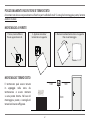 4
4
-
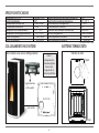 5
5
-
 6
6
-
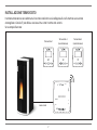 7
7
-
 8
8
-
 9
9
-
 10
10
-
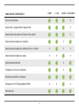 11
11
-
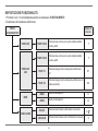 12
12
-
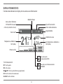 13
13
-
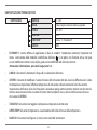 14
14
-
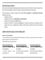 15
15
-
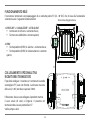 16
16
-
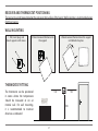 17
17
-
 18
18
-
 19
19
-
 20
20
-
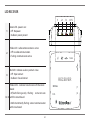 21
21
-
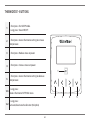 22
22
-
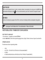 23
23
-
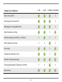 24
24
-
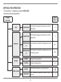 25
25
-
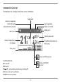 26
26
-
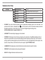 27
27
-
 28
28
-
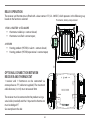 29
29
-
 30
30
-
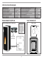 31
31
-
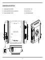 32
32
-
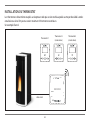 33
33
-
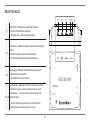 34
34
-
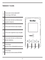 35
35
-
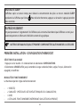 36
36
-
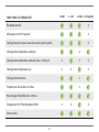 37
37
-
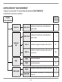 38
38
-
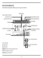 39
39
-
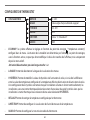 40
40
-
 41
41
-
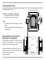 42
42
-
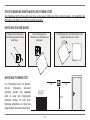 43
43
-
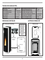 44
44
-
 45
45
-
 46
46
-
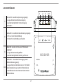 47
47
-
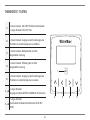 48
48
-
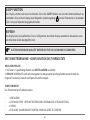 49
49
-
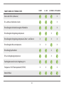 50
50
-
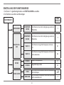 51
51
-
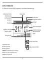 52
52
-
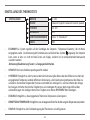 53
53
-
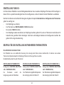 54
54
-
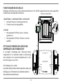 55
55
-
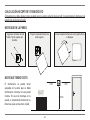 56
56
-
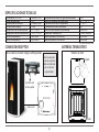 57
57
-
 58
58
-
 59
59
-
 60
60
-
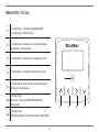 61
61
-
 62
62
-
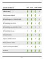 63
63
-
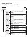 64
64
-
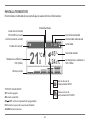 65
65
-
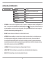 66
66
-
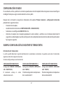 67
67
-
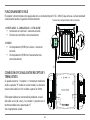 68
68
-
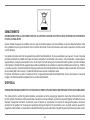 69
69
-
 70
70
-
 71
71
-
 72
72


Extraflame Kit Wireless thermostat El manual del propietario
- Categoría
- Componentes del dispositivo de seguridad
- Tipo
- El manual del propietario
en otros idiomas
Artículos relacionados
Otros documentos
-
claber Hydro-4 RF Guía del usuario
-
Ravelli HR EVO 14 Hydro El manual del propietario
-
Palazzetti EcoFire IDRO Installation, User And Maintenance Manual
-
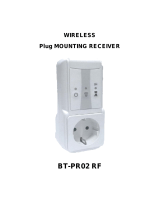 Watts Industries BT-PR02 RF Manual de usuario
-
Comelit Minitouch Installer Manual
-
 Bio Bronpi HYDRO Serie Installation, Operating And Service Instructions
-
Real Flame 770E-W Instrucciones de operación
-
Watts BT-WR02 Guía del usuario
-
Honeywell DT92E El manual del propietario

