Amprobe AMLAN-1 Manual de usuario
- Categoría
- Medición
- Tipo
- Manual de usuario
Este manual también es adecuado para

LAN-1
Lan Cable Tester
Users Manual
Mode d’emploi•
Bedienungshandbuch•
Manuale d’Uso•
Manual de uso•
Användarhandbok•

English
LAN-1
Lan Cable Tester
Users Manual
LAN1_Rev001
© 2008 Amprobe Test Tools.
All rights reserved.

2
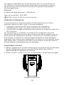
Limited Warranty and Limitation of Liability
Your Amprobe product will be free from defects in material and workmanship for
1 year from the date of purchase. This warranty does not cover fuses, disposable
batteries or damage from accident, neglect, misuse, alteration, contamination,
or abnormal conditions of operation or handling. Resellers are not authorized
to extend any other warranty on Amprobe’s behalf. To obtain service during the
warranty period, return the product with proof of purchase to an authorized
Amprobe Test Tools Service Center or to an Amprobe dealer or distributor. See
Repair Section for details. THIS WARRANTY IS YOUR ONLY REMEDY. ALL OTHER
WARRANTIES - WHETHER EXPRESS, IMPLIED OR STAUTORY - INCLUDING IMPLIED
WARRANTIES OF FITNESS FOR A PARTICULAR PURPOSE OR MERCHANTABILITY,
ARE HEREBY DISCLAIMED. MANUFACTURER SHALL NOT BE LIABLE FOR ANY
SPECIAL, INDIRECT, INCIDENTAL OR CONSEQUENTIAL DAMAGES OR LOSSES,
ARISING FROM ANY CAUSE OR THEORY. Since some states or countries do not
allow the exclusion or limitation of an implied warranty or of incidental or
consequential damages, this limitation of liability may not apply to you.
Repair
All test tools returned for warranty or non-warranty repair or for calibration
should be accompanied by the following: your name, company’s name, address,
telephone number, and proof of purchase. Additionally, please include a brief
description of the problem or the service requested and include the test leads
with the meter. Non-warranty repair or replacement charges should be remitted
in the form of a check, a money order, credit card with expiration date, or a
purchase order made payable to Amprobe® Test Tools.
*(Correspondence only – no repair or replacement available from this address.
European customers please contact your distributor.)

3
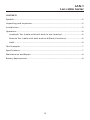
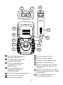
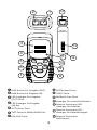
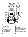
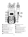
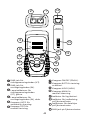
➊ RJ45 jack for sourcing end
(OUT).
➋ RJ45 jack for receiving end (IN).
➌
LED indicators for sourcing end
(OUT) Green.
➍ LED indicators for receiving end
(IN). Red.
➎ AUTO scan button.
➏ TEST button for MANUal test.
➐ POWER ON/OFF button.
➑ BATTery TEST button.
➒ HOLD button.
➓ MANUal scan button.
Low BATTery indicator.
Remote Terminator LED
indicator for ground wire
Remote Terminator LED
indicators for data lines
Remote Terminator RJ45 jack
HOLD
MAN
AUTO
TEST
BATT
1
2
3
4
5
6
7
9
8
REMOTE
TERMINATOR
IN OUT
1 2 3 4 5 6 7 8 G
OUT
IN
1
2
3
4
5
6
7
8
GRD
10
12
14
13
11

4
LAN-1
Lan cable tester
CONTENTS
Symbols ..................................................................................................................5
Unpacking and Inspection ....................................................................................5
Introduction ...........................................................................................................5
Operation ..............................................................................................................6
Loopback Test (cable with both ends in one location) ..................................6
Remote Test (cable with both ends at different locations) ...........................6
Hold ..................................................................................................................6
Test Examples ........................................................................................................7
Specifications .........................................................................................................7
Maintenance and Repair .....................................................................................8
Battery Replacement ............................................................................................8

5
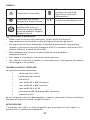
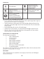
SYMBOLS
Refer to the manual Do not dispose of this
product as unsorted
municipal waste.
Conforms to relevant
Australian standards. Complies with EU
directives
This equipment not
for connection to
public communications
networks, such as active
telephone systems.
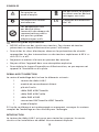
Warning and Precautions
DO NOT use on live circuits. These voltage levels pose a potential shock •
hazard to the user.
To avoid electrical shock hazard, observe the proper safety precautions •
when working with voltages above 60 VDC or 30 VAC rms.
Never ground yourself when taking measurements. •
Do not operate the instrument in an explosive atmosphere.•
To reduce the risk of fire or electric shock, do not expose this product to •
rain or moisture.
UNPACKING AND INSPECTION
Your shipping carton should include:
1 LAN-1 Cable tester
1 Remote Terminator
1 9 volt battery
1 RJ45 to female BNC cable
1 RJ45 to male BNC cable
1 RJ45 to RJ45 cable
1 female BNC to female BNC connector
1 Users Manual
If any of the items are damaged or missing, return the complete package to
the place of purchase for an exchange.
INTRODUCTION
The LAN-1 Cable Tester is designed for testing opens, shorts and miswired
cable installations .

6
Testing capabilities are:
Test pin configuration for 10/100 base -T cable, 10 base-2 cable, RJ45 •
modular cables, AT&T 258A cable, EIA / TIA 568A/568B cables and Token
Ring Cable etc.
Verify cable continuity, open, short or incorrectly wired.•
Test installed cable on wall plate or the patch panels by using the Remote •
Termination module.
Buzzer sound warning for error condition. •
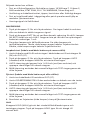
OPERATION
Press 1. button for power ON. If no cable is attached or cable is defective,
the buzzer will sound.
Press BATT to verify proper operating voltage. The BATT LED will not light 2.
and LAN-1 will not operate correctly if battery is below 7 volts.
Green LEDs are the source indicators. Red LED’s are the test indicators. 3.
Red LED’s ON indicate cable line continuity. Red LED’s OFF indicate open
cable lines.
Loopback Test (cable with both ends in one location)
Connect cable with RJ-45 terminations on both ends to IN and OUT test 1.
sockets.
Press 2. button for power ON. Press AUTO (default) or MAN button to
start scanning.
AUTO scanning will step through lines 1 to 8 and ground (if connected) 3.
and repeats until stopped.
MAN scanning will go into manual mode and TEST will step through the 4.
different lines.
Remote Test (cable with both ends at different locations)
Connect one cable end to OUT connector.1.
Connect REMOTE TERMINATOR to the other end of cable under test.2.
Press 3. button for power ON. Press AUTO (default) or MAN button to
start scanning.
AUTO scanning will step through lines 1 to 8 and ground (if connected) 4.
and repeat until stopped.
MAN scanning go into manual mode and TEST will step through the 5.
different lines.
Line test results (Red LED’s) are shown on the Remote Terminator.6.
Hold
The HOLD button saves the displayed error condition and stops testing. Press
the HOLD button to return to normal operation.

7
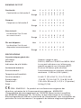
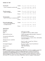
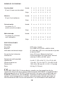
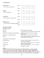
TEST EXAMPLES
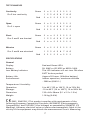
Continuity Green onooooooo
Pin 2 has continuity 1 2 3 4 5 6 7 8 G
Red onooooooo
Open Green onooooooo
Pin 2 is open 1 2 3 4 5 6 7 8 G
Red ooooooooo
Short Green onnoooooo
Pins 2 and 3 are shorted 1 2 3 4 5 6 7 8 G
Red onnoooooo
Miswire Green onooooooo
Pins 2 and 6 are miswired 1 2 3 4 5 6 7 8 G
Red ooooonooo
SPECIFICATIONS
General
Display: Red and Green LED’s
Battery: 9V, 006P or IEC 6F22 or NEDA 1604.
Low Battery Indicator: The LED indicator will not turn ON when
BATT button pushed
Battery Life: Approx 20 hours. (Alkaline battery)
Environment: Indoor operation, maximum altitude
- 2000 m (6561 ft.)
Temperature / Humidity:
Operation: 0 to 40°C (32 to 104°F), 10 to 70% RH.
Storage: -10 to 60°C (14 to 140°F), 10 to 90% RH.
Dimension: 130 x 64 x 38mm (5.1 x 2.2 x 1.5 in)
Weight: 1.26 kg (0.6 lb)
-EMC: EN61326-1 This product complies with requirements of the
following European Community Directives: 89/336/EEC (Electromagnetic
Compatibility) and 73/23/EEC (Low Voltage) as amended by 93/68/EEC (CE
Marking). However, electrical noise or intense electromagnetic fields in the
vicinity of the equipment may disturb the measurement circuit. Measuring

8
instruments will also respond to unwanted signals that may be present within
the measurement circuit. Users should exercise care and take appropriate
precautions to avoid misleading results when making measurements in the
presence of electronic interference.
Electrical
Maximum line length: ~300 meters
Connector types: RJ45, BNC
DO NOT use on live circuits.
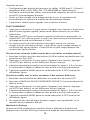
MAINTENANCE AND REPAIR
If there appears to be a malfunction during the operation of the tester, the
following steps should be performed in order to isolate the cause of the
problem.
Press the BATTery button to check the battery. Replace the battery 1.
immediately if the LED indicator will not turn ON.
Review the operating instructions for possible mistakes in operating 2.
procedure.
Except for the replacement of the battery, repair of the meter should be
performed only by a Factory Authorized Service Center or by other qualified
instrument service personnel. The front panel and case can be cleaned with
a mild solution of detergent and water. Apply sparingly with a soft cloth and
allow to dry completely before using. Do not use aromatic hydrocarbons or
chlorinated solvents for cleaning.
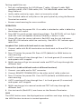
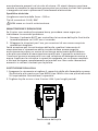
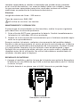
BATTERY REPLACEMENT
1. Turn off the meter and slide out the battery cover. Replace the battery with
a NEDA type 1604 or equivalent 9V alkaline battery. Replace the cover.
2. Remove battery when the LAN-1 is not used for extended period.
OPEN
Battery Replacement

9
LAN1_Rev001
© 2008 Amprobe Test Tools.
Tous droits réservés.
LAN-1
Testeur de câbles LAN
Mode d’emploi
Français

10
Limites de garantie et de responsabilité
Amprobe garantit l’absence de vices de matériaux et de fabrication de ce produit dans des
conditions normales d’utilisation et d’entretien pendant une période d’un (1) an prenant
effet à la date d’achat. Cette garantie ne s’applique pas aux fusibles, aux piles jetables
ni à tout produit mal utilisé, modifié, contaminé, négligé ou endommagé par accident
ou soumis à des conditions anormales d’utilisation et de manipulation. Les distributeurs
agréés par Amprobe ne sont pas autorisés à appliquer une garantie plus étendue au
nom d’Amprobe. Pour bénéficier de la garantie, renvoyez le produit accompagné d’un
justificatif d’achat auprès d’un centre de services agréé par Amprobe Test Tools, d’un
distributeur ou d’un revendeur Amprobe. Voir la section Réparation pour tous les détails.
LA PRESENTE GARANTIE EST LE SEUL ET EXCLUSIF RECOURS. TOUTES AUTRES GARANTIES,
EXPLICITES, IMPLICITES OU STATUTAIRES, NOTAMMENT LE CAS ECHEANT LES GARANTIES
DE QUALITE MARCHANDE OU D’ADAPTATION A UN OBJECTIF PARTICULIER, SONT
EXCLUES PAR LES PRESENTES. LE FABRICANT NE SERA EN AUCUN CAS TENU RESPONSABLE
DES DOMMAGES PARTICULIERS, INDIRECTS, ACCIDENTELS OU CONSECUTIFS, NI
D’AUCUNS DEGATS OU PERTES DE DONNEES, SUR UNE BASE CONTRACTUELLE, EXTRA-
CONTRACTUELLE OU AUTRE. Etant donné que certaines juridictions n’admettent pas les
limitations d’une condition de garantie implicite, ou l’exclusion ou la limitation de dégâts
accidentels ou consécutifs, il se peut que les limitations et/ou les exclusions de cette
garantie ne s’appliquent pas à votre cas.
Réparation
Tous les outils de test renvoyés pour une réparation ou un étalonnage ou couvert ou
non par la garantie doivent être accompagnés des éléments suivants : nom, raison
sociale, adresse, numéro de téléphone et justificatif d’achat. Ajoutez également une
brève description du problème ou du service demandé et incluez les cordons de test
avec l’appareil. Les frais de remplacement ou de réparation hors garantie doivent être
acquittés par chèque, mandat, carte de crédit avec date d’expiration ou par bon de
commande payable à l’ordre de Amprobe® Test Tools.

11
HOLD
MAN
AUTO
TEST
BATT
1
2
3
4
5
6
7
9
8
REMOTE
TERMINATOR
IN OUT
1 2 3 4 5 6 7 8 G
OUT
IN
1
2
3
4
5
6
7
8
GRD
10
12
14
13
11
➊ Prise RJ45 de l’extrémité
émission (SORTIE).
➋ Prise RJ45 de l’extrémité
réception (ENTREE).
➌
Voyants indicateurs de
l’extrémité émission
(SORTIE) Vert.
➍ Voyants indicateurs de
l’extrémité réception
(ENTREE) Rouge.
➎ Bouton d’analyse automatique.
➏ Bouton de test manuel.
➐ Bouton marche/arrêt.
➑ Bouton de test de pile.
➒ Maintien d’affichage.
➓ Bouton d’analyse manuelle.
Indicateur de pile faible.
Voyant indicateur du module
de raccordement distant : fil
de terre.
Voyants indicateurs du module
de raccordement distant : lignes
de données.
Prise RJ45 du module de
raccordement distant.

12
Symboles ..............................................................................................................13
Deballage et inspection ......................................................................................13
Introduction .........................................................................................................13
Fonctionnement ..................................................................................................14
Test de retour en boucle
(câble avec les deux extrémités au même endroit) .....................................14
Test distant
(câble avec les deux extrémités à des endroits différents) ..........................14
Maintien d’affichage .....................................................................................14
Exemples de test ..................................................................................................15
Specifications .......................................................................................................15
Entretien et reparation ......................................................................................16
Changement des piles ........................................................................................16
LAN-1
Testeur de câbles LAN

13
SYMBOLES
Se reporter au
mode d’emploi. Ne pas mettre ce produit
au rebut avec les déchets
ménagers non triés.
Conforme aux normes
australiennes. Conforme aux directives
de l’UE.
Cet équipement n’est
pas destiné à être
connecté à des réseaux de
communications publics
tels que les systèmes
téléphoniques actifs.
Mises en garde et précautions
NE PAS utiliser sur des circuits sous tension. Ces niveaux de tension •
présentent un risque d’électrocution pour l’utilisateur.
Pour éviter les chocs électriques, observer les précautions de sécurité •
appropriées lors des interventions sur des tensions supérieures à 60 V c.c.
ou à 30 V c.a. eff.
Ne jamais se mettre à la terre en prenant des mesures. •
Ne pas utiliser l’appareil dans une atmosphère explosive.•
Pour réduire le risque d’incendie ou d’électrocution, ne pas exposer cet •
appareil à l’humidité ou à la pluie.
DEBALLAGE ET INSPECTION
Le carton d’emballage doit inclure les éléments suivants :
1 testeur de câbles LAN-1
1 module de raccordement distant
1 pile de 9 volts
1 câble RJ45 à BNC femelle
1 câble RJ45 à BNC mâle
1 câble RJ45 à RJ45
1 connecteur BNC femelle à BNC femelle
1 mode d’emploi
Si l’un de ces éléments est endommagé ou manquant, renvoyez le contenu
complet de l’emballage au lieu d’achat pour l’échanger.
INTRODUCTION
Le testeur de câbles LAN-1 est conçu pour tester les coupures, les courts-
circuits et les installations de câbles incorrectement disposés.

14
Capacités de test :
Configuration des broches de test pour les câbles 10/100 base-T, 10 base-2, •
modulaires RJ45, AT&T 258A, EIA / TIA 568A/568B et Token Ring etc.
Vérifiez la continuité des câbles, la présence de coupures, de courts-circuits •
ou de fils incorrectement disposés.
Testez le câble installé sur la plaque murale ou sur les panneaux de •
raccordement en utilisant le module de raccordement distant.
L’avertisseur retentit pour signaler une condition d’erreur. •
FONCTIONNEMENT
Appuyez sur le bouton 1. pour mettre l’appareil sous tension. L’avertisseur
retentit pour signaler signale l’absence de câble connecté ou un câble
défectueux.
Appuyez sur BATT pour confirmer la tension d’utilisation appropriée. Le 2.
voyant BATT ne s’allume pas et le LAN-1 ne fonctionne pas correctement si
la charge de la pile est inférieure à 7 volts.
Les voyants verts sont les indicateurs du signal source. Les voyants 3.
rouges sont les indicateurs de test. L’activité du voyant rouge indique la
continuité des lignes câblées. L’inactivité du voyant rouge indique une
coupure des lignes câblées.
Test de retour en boucle (câble avec les deux extrémités au même endroit)
Branchez le câble muni de terminaisons RJ-45 aux deux extrémités dans les 1.
prises de test IN et OUT.
Appuyez sur le bouton 2. pour mettre l’appareil sous tension. Appuyez
sur AUTO (par défaut) ou sur MAN pour lancer l’analyse.
L’analyse automatique analyse consécutivement les lignes 1 à 8 et la terre 3.
(si connectée) et répète l’opération tant qu’elle n’est pas interrompue.
L’analyse manuelle (MAN) passe en mode manuel et le TEST analyse les 4.
différentes lignes.
Test distant (câble avec les deux extrémités à des endroits différents)
Branchez une extrémité du câble dans le connecteur de sortie OUT.1.
Branchez le MODULE DE RACCORDEMENT DISTANT à l’autre extrémité du 2.
câble à tester.
Appuyez sur le bouton 3. pour mettre l’appareil sous tension. Appuyez
sur AUTO (par défaut) ou sur MAN pour lancer l’analyse.
L’analyse automatique analyse consécutivement les lignes 1 à 8 et la terre 4.
(si connectée) et répète l’opération tant qu’elle n’est pas interrompue.
L’analyse manuelle (MAN) passe en mode manuel et le TEST analyse les 5.
différentes lignes.
Les résultats des tests de ligne (voyants rouges) sont représentés sur le 6.
module de raccordement distant.
Maintien d’affichage
Le bouton HOLD enregistre la condition d’erreur affichée et arrête le test.
Appuyez sur le bouton HOLD pour revenir en mode de fonctionnement normal.

15
EXEMPLES DE TEST
Continuité Vert onooooooo
Continuité sur la broche 2 1 2 3 4 5 6 7 8 G
Rouge onooooooo
Coupure Vert onooooooo
Coupure sur la broche 2 1 2 3 4 5 6 7 8 G
Rouge ooooooooo
Court-circuit Vert onnoooooo
Les broches 2 et 3 sont
en court-circuit 1 2 3 4 5 6 7 8 G
Rouge onnoooooo
Fils mal disposés Vert onooooooo
Les broches 2 et 6 sont
disposées incorrectement 1 2 3 4 5 6 7 8 G
Rouge ooooonooo
SPECIFICATIONS
Caractéristiques générales
Affichage : Voyants rouge et vert
Batterie : Pile 9 V, 006P ou CEI 6F22 ou NEDA 1604
Indicateur de pile faible : Le voyant indicateur ne s’allume pas
quand on appuie sur le bouton BATT.
Autonomie batterie : Environ 20 heures (pile alcaline)
Environnement : Fonctionnement en intérieur, altitude
maximum : 2 000 m (6 561 pieds.)
Température/Humidité :
Fonctionnement : 0 à 40 °C (32 à 104 °F), 10 à 70 % HR
Entreposage : -10 à 60 °C (14 à 140 °F), 10 à 90 % HR
Dimensions : 130 x 64 x 38 mm (5,1 x 2,2 x 1,5 pouces)
Poids : 0,6 kg (1,2 lb)
-CEM : EN61326-1. Ce produit est conforme aux exigences des
directives suivantes de la Communauté européenne : 89/336/CEE
(Compatibilité électromagnétique) et 73/23/CEE (Basse tension) modifiée
par 93/68/CEE (Marquage CE). Toutefois, le bruit électrique ou les champs
électromagnétiques intenses à proximité de l’équipement sont susceptibles de
perturber le circuit de mesure. Les appareils de mesure réagissent également

16
OPEN
Changement des piles
aux signaux indésirables qui seraient présents dans le circuit de mesure.
Les utilisateurs doivent faire preuve de prudence et prendre les mesures
nécessaires pour éviter les erreurs de mesure en présence de parasites
électromagnétiques.
Electricité
Longueur de ligne maximum : ~300 mètres
Types de connecteur : RJ45, BNC
NE PAS utiliser sur des circuits sous tension.
ENTRETIEN ET REPARATION
Si une anomalie est suspectée pendant le fonctionnement du testeur,
procédez comme suit pour isoler la cause du problème.
Appuyez sur le bouton BATT pour vérifier la pile. Remplacez 1.
immédiatement la pile si le voyant indicateur ne s’allume pas.
Consultez les consignes d’utilisation pour vérifier les erreurs possibles lors 2.
de l’utilisation.
Les interventions sur l’appareil, à l’exception du changement des piles,
doivent être effectuées en usine dans un centre de services agréé ou par un
autre personnel de réparation qualifié. La face avant et le boîtier peuvent
être nettoyés à l’aide d’une solution légère à base d’eau et de détergent.
Appliquez cette solution avec modération en utilisant un tissu doux et laissez
bien sécher avant l’utilisation. N’utilisez pas de solvants à base de chlore ou
d’hydrocarbures aromatiques pour le nettoyage.
CHANGEMENT DES PILES
1. Mettez l’appareil hors tension et faites glisser le couvercle du compartiment
de pile. Remplacez la pile par une pile alcaline NEDA type 1604 ou
équivalente de 9 V. Replacez le couvercle.
2. Retirez la pile si le LAN-1 n’est pas utilisé pendant une période prolongée.

17
LAN1_Rev001
© 2008 Amprobe Test Tools.
Alle Rechte vorbehalten.
LAN-1
LAN-Kabel-Tester
Bedienungshandbuch
Deutsch

Beschränkte Gewährleistung und Haftungsbeschränkung
Es wird gewährleistet, dass dieses Amprobe-Produkt für die Dauer von einem Jahr ab
dem Kaufdatum frei von Material- und Fertigungsdefekten ist. Diese Gewährleistung
erstreckt sich nicht auf Sicherungen, Einwegbatterien oder Schäden durch Unfälle,
Nachlässigkeit, Missbrauch, Änderungen oder abnormale Betriebsbedingungen
bzw. unsachgemäße Handhabung. Die Verkaufsstellen sind nicht dazu berechtigt,
diese Gewährleistung im Namen von Amprobe zu erweitern. Um während der
Gewährleistungsperiode Serviceleistungen in Anspruch zu nehmen, das Produkt mit
Kaufnachweis an ein autorisiertes Amprobe Test Tools Service-Center oder an einen
Amprobe-Fachhändler/-Distributor einsenden. Nähere Einzelheiten siehe Abschnitt
„Reparatur“. DIESE GEWÄHRLEISTUNG STELLT DEN EINZIGEN UND ALLEINIGEN
RECHTSANSPRUCH AUF SCHADENERSATZ DAR. ALLE ANDEREN GEWÄHRLEISTUNGEN,
VERTRAGLICH GEREGELTE ODER GESETZLICHE VORGESCHRIEBENE, EINSCHLIESSLICH
DER GESETZLICHEN GEWÄHRLEISTUNG DER MARKTFÄHIGKEIT UND DER EIGNUNG
FÜR EINEN BESTIMMTEN ZWECK, WERDEN ABGELEHNT. DER HERSTELLER ÜBERNIMMT
KEINE HAFTUNG FÜR SPEZIELLE, INDIREKTE, NEBEN- ODER FOLGESCHÄDEN ODER
FÜR VERLUSTE, DIE AUF BELIEBIGER URSACHE ODER RECHTSTHEORIE BERUHEN. Weil
einige Staaten oder Länder den Ausschluss oder die Einschränkung einer implizierten
Gewährleistung sowie den Ausschluss von Begleit- oder Folgeschäden nicht zulassen, ist
diese Gewährleistungsbeschränkung möglicherweise für Sie nicht gültig.
Reparatur
Allen Geräten, die innerhalb oder außerhalb des Garantiezeitraums zur Reparatur
oder Kalibrierung eingesendet werden, müssen mit folgenden Informationen und
Dokumenten versehen werden: Name des Kunden, Firmenname, Adresse, Telefonnummer
und Kaufbeleg. Zusätzlich bitte dem Messgerät eine kurze Beschreibung des Problems
oder der gewünschten Wartung sowie die Messleitungen beilegen. Die Gebühren
für außerhalb des Garantiezeitraums durchgeführte Reparaturen oder für den
Ersatz von Instrumenten müssen per Scheck, Zahlungsanweisung oder Kreditkarte
(Kreditkartennummer mit Ablaufdatum) beglichen werden oder es muss ein Auftrag auf
Rechnung an Amprobe® Test Tools formuliert werden.

19
HOLD
MAN
AUTO
TEST
BATT
1
2
3
4
5
6
7
9
8
REMOTE
TERMINATOR
IN OUT
1 2 3 4 5 6 7 8 G
OUT
IN
1
2
3
4
5
6
7
8
GRD
10
12
14
13
11
➊ RJ45-Buchse für Ausgabe (OUT).
➋ RJ45-Buchse für Eingabe (IN).
➌
LED-Anzeiger für Ausgabe
(OUT) Grün.
➍ LED-Anzeiger für Eingabe
(IN) Rot.
➎ AUTO-Scan-Taste.
➏ TEST-Taste für MANUELLEN Test.
➐ EIN-/AUS-Taste.
➑ BATTerietest-Taste.
➒ HOLD-Taste.
➓ MANuell-Scan-Taste.
Anzeiger für schwache Batterie.
Remote Terminator-LED-
Anzeiger für Erdleiter.
Remote Terminator-LED-
Anzeiger für Datenleitungen.
Remote Terminator-
RJ45-Buchse.

20
Symbole ...............................................................................................................21
Auspacken und Überprüfen ...............................................................................21
Einführung ...........................................................................................................21
Bedienung ...........................................................................................................22
Schleifentest (Kabel mit zwei Enden an einem Standort) ...........................22
Remote-Test (Kabel mit zwei Enden an unterschiedlichen Standorten) ....22
Hold ................................................................................................................22
Testbeispiele ........................................................................................................23
Spezifikationen ...................................................................................................23
Wartung und Reparatur ....................................................................................24
Ersetzen der Batterie .........................................................................................24
LAN-1
LAN-Kabel-Tester

21
SYMBOLE
Im Handbuch nachlesen. Dieses Produkt nicht
im unsortierten
Kommunalabfall
entsorgen.
Übereinstimmung
mit den relevanten
australischen Normen. Übereinstimmung mit
EU-Vorschriften.
Dieses Gerät nicht
an öffentliche
Kommunikations-
netzwerke (z.B. aktive
Telefon systeme)
anschließen.
Warn- und Vorsichtshinweise
NICHT an stromführenden Schaltkreisen verwenden. Diese Spannungen •
stellen eine Stromschlaggefahr für den Bediener dar.
Zur Vermeidung von Stromschlaggefahr bei Arbeiten mit Spannungen •
oberhalb 60 V Gleichspannung bzw. 30 V Wechselspannung eff. die
ordnungsgemäßen Sicherheits vorkehrungen einhalten.
Sich selbst isolieren, wenn Messungen durchgeführt werden. •
Das Messgerät nicht in Umgebungen mit explosiven Gasen betreiben.•
Um das Risiko von Feuer und Stromschlag zu verringern, dieses Produkt •
nicht Regen oder Feuchtigkeit aussetzen.
AUSPACKEN UND ÜBERPRÜFEN
Der Verpackungskarton sollte Folgendes enthalten:
1 LAN-1 Kabeltester
1 Remote Terminator
1 9-Volt-Batterie
1 RJ45 auf BNC-Kabel (Buchse)
1 RJ45 auf BNC-Kabel (Stecker)
1 RJ45 auf RJ45-Kabel
1 BNC (Buchse) auf BNC-Steckverbinder (Buchse)
1 Bedienungshandbuch
Wenn einer dieser Artikel beschädigt ist oder fehlt, die gesamte Lieferung
zwecks Ersatz an die Verkaufsstelle zurücksenden.
EINFÜHRUNG
Der LAN-1 Kabeltester eignet sich zum Testen von offenen, kurzgeschlossenen
und falsch verdrahteten Schaltkreisen von Kabelinstallationen.

22
Die Testfunktionalität umfasst:
Testen der Stiftbelegung für 10/100 Base-T-Kabel, 10 Base-2-Kabel, RJ45-•
Kabel, AT&T 258-Kabel, EIA / TIA 568A/568B-Kabel, Token Ring-Kabel usw.
Verifizieren von Kabeldurchgang, offenen, kurzgeschlossenen oder falsch •
verdrahteten Schaltkreisen.
Testen installierter Kabel an Anschlussdose oder Rangierfeld unter •
Verwendung des Remote Terminator-Moduls.
Summer-Warnton für Fehlerbedingung. •
BEDIENUNG
Die Taste 1. drücken, um EINZUSCHALTEN. Falls kein Kabel angeschlossen
bzw. das Kabel defekt ist, ertönt der Summer.
BATT drücken, um korrekte Betriebsspannung zu verifizieren. Falls die 2.
Batteriespannung weniger als 7 Volt beträgt, leuchtet die BATT-LED nicht
auf und der LAN-1 funktioniert nicht ordnungsgemäß.
Grüne LEDs sind Quellenanzeiger. Rote LEDs sind Testanzeiger. Rote 3.
leuchtende LEDs zeigen Kabeldurchgang an. Rote, nicht leuchtende LEDs
zeigen offene Kabel an.
Schleifentest (Kabel mit zwei Enden an einem Standort)
Kabel mit RJ45-Abschlüssen an beiden Enden an die Testanschlüsse IN und 1.
OUT anschließen.
Die Taste 2. drücken, um EINZUSCHALTEN. AUTO (Standard) oder MAN
drücken, um den Scan-Vorgang zu starten.
AUTO-Scan durchläuft die Leitungen 1 bis 8 plus Erde (falls angeschlossen) 3.
und wiederholt sich, bis der Vorgang abgebrochen wird.
MAN-Scan schaltet in den manuellen Modus und TEST durchläuft 4.
verschiedene Leitungen.
Remote-Test (Kabel mit zwei Enden an unterschiedlichen Standorten)
Ein Kabelende an den Anschluss OUT anschließen.1.
Den REMOTE TERMINATOR an das andere Ende des zu prüfenden Kabels 2.
anschließen.
Die Taste 3. drücken, um EINZUSCHALTEN. AUTO (Standard) oder MAN
drücken, um den Scan-Vorgang zu starten.
AUTO-Scan durchläuft die Leitungen 1 bis 8 plus Erde (falls angeschlossen) 4.
und wiederholt sich, bis der Vorgang abgebrochen wird.
MAN-Scan schaltet in den manuellen Modus und TEST durchläuft 5.
verschiedene Leitungen.
Leitungstestergebnisse (rote LEDs) werden auf dem Remote Terminator 6.
angezeigt.
Hold
Die Taste HOLD speichert die angezeigte Fehlerbedingung und stoppt
den Testvorgang. Die Taste HOLD drücken, um zum Normalbetrieb
zurückzukehren.

23
TESTBEISPIELE
Durchgang Grün onooooooo
Stift 2 hat Durchgang 1 2 3 4 5 6 7 8 G
Rot onooooooo
Offen Grün onooooooo
Stift 2 ist offen 1 2 3 4 5 6 7 8 G
Rot ooooooooo
Kurzschluss Grün onnoooooo
Die Stifte 2 und 3 sind
kurzgeschlossen 1 2 3 4 5 6 7 8 G
Rot onnoooooo
Fehlverdrahtung Grün onooooooo
Die Stifte 2 und 3 sind
falsch verdrahtet 1 2 3 4 5 6 7 8 G
Rot ooooonooo
SPEZIFIKATIONEN
Allgemein
Anzeige: Rote und grüne LEDs
Batterie: 9 V, 006P oder IEC 6F22 oder NEDA 1604
Anzeige für schwache Batterie: LED-Anzeige leuchtet nicht, wenn die
Taste BATT gedrückt wird
Batterielebensdauer: Ungefähr 200 Stunden (Alkalibatterie)
Umgebung: Betrieb in Gebäuden, max. Höhenlage
2000 m
Temperatur / Feuchtigkeit:
Betrieb: 0 bis 40 °C, 10 bis 70 % RH
Lagerung: -10 bis 60 °C, 10 bis 90 % RH
Abmessungen: 130 x 64 x 38 mm
Gewicht: 0,6 kg
-EMV: EN61326-1. Dieses Produkt erfüllt die Anforderungen der
folgenden EU-Richtlinien: 89/336/EEC (Elektromagnetische Verträglichkeit)
und 73/23/EEC (Niederspannung) mit dem Zusatz 93/68/EEC (CE-
Kennzeichnung). Elektrisches Rauschen oder intensive elektromagnetische
Felder in der Nähe des Geräts können jedoch den Messschaltkreis stören.

24
OPEN
Ersetzen der Batterie
Messgeräte reagieren auch auf unerwünschte Impulse/Signale, die unter
Umständen im Messschaltkreis vorkommen. Die Benutzer müssen die nötige
Sorgfalt walten lassen und geeignete Vorkehrungen treffen, um irreführende
Ergebnisse bei Messungen zu vermeiden, wenn elektronische Störeinflüsse
vorhanden sind.
Elektrik
Maximale Leitungslänge: ~300 m
Anschlusstypen: RJ45, BNC
NICHT an stromführenden Schaltkreisen verwenden.
WARTUNG UND REPARATUR
Wenn ein Fehlverhalten während des Betriebs des Testers vermutet wird,
sollten die folgenden Schritte durchgeführt werden, um die Ursache des
Problems genau zu bestimmen.
Die Taste BATT drücken, um die Batterie zu prüfen. Die Batterie sofort 1.
ersetzen, falls der LED-Anzeiger nicht zu leuchten beginnt.
Die Bedienungsanleitungen studieren, um mögliche Fehler bei der 2.
Bedienung zu erkennen.
Außer dem Ersetzen der Batterie sollten Reparaturen am Messgerät
ausschließlich durch werkseitig autorisiertes Servicepersonal oder anderes
Fachpersonal durchgeführt werden. Die Vorderseite und das Gehäuse
können mit einer milden Lösung von Reinigungsmittel und Wasser gereinigt
werden. Die Lösung spärlich mit einem weichen Tuch anwenden und
das Gerät vor Gebrauch vollständig trocknen lassen. Keine aromatischen
Kohlenwasserstoffe oder Chlorlösungsmittel zur Reinigung verwenden.
ERSETZEN DER BATTERIE
1. Das Messgerät ausschalten und die Batterieabdeckung aufschieben.
Die Batterie durch eine NEDA Typ 1604 oder eine gleichwertige
9-V-Alkalibatterie ersetzen. Die Abdeckung wieder anbringen.
2. Die Batterie entfernen, wenn der LAN-1 längere Zeit nicht verwendet wird.

25
LAN1_Rev001
© 2008 Amprobe Test Tools.
Tutti i diritti riservati.
LAN-1
Tester per cavi LAN
Manuale d’Uso
Italiano

26
Garanzia limitata e limitazione di responsabilità
Questo prodotto Amprobe sarà esente da difetti di materiale e fabbricazione per un
anno a decorrere dalla data di acquisto. Sono esclusi da questa garanzia i fusibili, le
pile monouso e i danni causati da incidenti, negligenza, uso improprio, alterazione,
contaminazione o condizioni anomale di funzionamento o manipolazione. I rivenditori
non sono autorizzati a offrire nessun’altra garanzia a nome della Amprobe. Per richiedere
un intervento durante il periodo di garanzia, restituire il prodotto, allegando la ricevuta
di acquisto, a un centro di assistenza autorizzato Amprobe Test Tools oppure a un
rivenditore o distributore Amprobe locale. Per ulteriori informazioni vedere la sezione
Riparazioni. QUESTA GARANZIA È IL SOLO RICORSO A DISPOSIZIONE DELL’ACQUIRENTE
E SOSTITUISCE QUALSIASI ALTRA GARANZIA, ESPRESSA, IMPLICITA O PREVISTA DALLA
LEGGE, COMPRESA, MA NON A TITOLO ESCLUSIVO, QUALSIASI GARANZIA IMPLICITA DI
COMMERCIABILITÀ O DI IDONEITÀ PER SCOPI PARTICOLARI. IL PRODUTTORE NON SARÀ
RESPONSABILE DI DANNI O PERDITE SPECIALI, INDIRETTI O ACCIDENTALI, DERIVANTI DA
QUALSIASI CAUSA O TEORIA. Poiché alcuni stati o Paesi non permettono l’esclusione o la
limitazione di una garanzia implicita o di danni accidentali o indiretti, questa limitazione
di responsabilità potrebbe non riguardare l’acquirente.
Riparazioni
A tutti gli strumenti di misura restituiti per interventi in garanzia o non coperti dalla
garanzia, oppure per la taratura, devono essere allegate le seguenti informazioni: il
proprio nome e quello dell’azienda, indirizzo, numero telefonico e ricevuta di acquisto.
Allegare anche una breve descrizione del problema o dell’intervento richiesto e i cavi di
misura. Gli importi dovuti per sostituzioni o riparazioni non coperte dalla garanzia vanno
versati tramite assegno, vaglia bancario, carta di credito con data di scadenza, oppure
ordine di acquisto all’ordine di Amprobe® Test Tools.

27
HOLD
MAN
AUTO
TEST
BATT
1
2
3
4
5
6
7
9
8
REMOTE
TERMINATOR
IN OUT
1 2 3 4 5 6 7 8 G
OUT
IN
1
2
3
4
5
6
7
8
GRD
10
12
14
13
11
➊ Connettore RJ-45 per
l’estremità di generazione
del segnale (OUT).
➋ Connettore RJ-45 per l’estremità
di ricezione (IN).
➌
LED per l’estremità di
generazione (OUT), verdi.
➍ LED per l’estremità di
ricezione (IN), rossi.
➎ Pulsante di scansione
automatica.
➏ Pulsante TEST per test manuali.
➐ Pulsante di accensione/
spegnimento.
➑ Pulsante di test della pila.
➒ Pulsante HOLD.
➓ Pulsante di scansione manuale.
Spia di bassa carica della pila.
LED della terminazione remota
per il filo di terra.
LED della terminazione remota
per linee dati.
Connettore RJ-45 della
terminazione remota.

28
Simboli .................................................................................................................29
Disimballaggio e ispezione .................................................................................29
Introduzione ........................................................................................................29
Funzionamento ...................................................................................................30
Test di loopback (cavo con entrambe le estremità nello stesso punto) .....30
Test remoto (cavo con le estremità in punti diversi) ...................................30
Hold ................................................................................................................30
Esempi di test ......................................................................................................31
Specifiche .............................................................................................................31
Manutenzione e riparazioni ...............................................................................32
Sostituzione della pila .........................................................................................32
LAN-1
Tester per cavi LAN

29
SIMBOLI
Consultare il manuale. Non smaltire questo
prodotto assieme ad
altri rifiuti solidi non
differenziati.
Conforme alle norme
australiane di pertinenza. Conforme alle direttive UE.
Non collegare questo
apparecchio a reti di
comunicazione pubblica,
quali ad esempio impianti
telefonici attivi.
Avvertenze e precauzioni
NON usare su circuiti sotto tensione. Questi livelli di tensione •
rappresentano un possibile rischio di folgorazione per gli utenti.
Per prevenire le scosse elettriche, osservare le precauzioni appropriate •
quando si lavora con tensioni maggiori di 60 V a corrente continua o 30 V
(valore efficace) a corrente alternata.
Non collegare mai sé stessi al potenziale di terra quando si •
eseguono misure.
Non usare lo strumento in un’atmosfera esplosiva.•
Per ridurre il rischio di incendio o scosse elettriche, non esporre il prodotto •
alla pioggia o all’umidità.
DISIMBALLAGGIO E ISPEZIONE
La confezione deve contenere:
1 tester per cavi LAN-1
1 terminazione remota
1 pila da 9 V
1 cavo da RJ-45 a BNC femmina
1 cavo da RJ-45 a BNC maschio
1 cavo da RJ-45 a RJ-45
1 connettore BNC femmina–BNC femmina
1 manuale d’Uso
Se uno di questi articoli è danneggiato o manca, restituire l’intera confezione
al punto di acquisto perché venga sostituita.
INTRODUZIONE
Il tester per cavi LAN-1 è stato progettato per le prove su circuiti aperti, in
cortocircuito o cablati erroneamente.

30
Le caratteristiche di prova sono le seguenti.
Test della piedinatura per cavi 10/100 base-T, 10 base-2, modulari RJ-45, •
AT&T 258A, EIA / TIA 568A/568B, Token Ring, ecc.
Verifica di continuità dei cavi, circuiti aperti, cortocircuiti o cablaggi errati.•
Test di cavi collegati a quadri o placche da parete usando il modulo di •
terminazione remota.
Cicalino di avvertenza in presenza di errori. •
FUNZIONAMENTO
Premere il pulsante 1. per accendere lo strumento. Se allo strumento non
è collegato alcun cavo o se il cavo è difettoso, il cicalino suona.
Premere BATT per verificare la tensione di alimentazione. Se la pila ha 2.
una carica inferiore a 7 V, il LED BATT non si accende e il tester LAN-1 non
funziona correttamente.
I LED verdi sono gli indicatori dell’origine. I LED rossi sono gli indicatori di 3.
test. Quando i LED rossi sono accesi, indicano continuità nel cavo. Quando
sono spenti, indicano un circuito aperto.
Test di loopback (cavo con entrambe le estremità nello stesso punto)
Collegare il cavo con due terminazioni RJ-45 ai connettori di test IN e OUT.1.
Premere il pulsante 2. per accendere lo strumento. Premere il pulsante
AUTO (impostazione predefinita) o MAN per iniziare la scansione.
La modalità automatica esegue la scansione delle linee da 1 a 8 e della 3.
terra (se collegata), ripetendo i test finché non viene fermata.
Il pulsante MAN attiva la modalità manuale, mentre il pulsante TEST 4.
permette di passare da una linea all’altra.
Test remoto (cavo con le estremità in punti diversi)
Collegare una estremità del cavo al connettore OUT.1.
Collegare la TERMINAZIONE REMOTA all’altra estremità del cavo 2.
sotto test.
Premere il pulsante 3. per accendere lo strumento. Premere il pulsante
AUTO (impostazione predefinita) o MAN per iniziare la scansione.
La modalità automatica esegue la scansione delle linee da 1 a 8 e della 4.
terra (se collegata), ripetendo i test finché non viene fermata.
Il pulsante MAN attiva la modalità manuale, mentre il pulsante TEST 5.
permette di passare da una linea all’altra.
I risultati dei test sulla linea (LED rossi) sono visualizzati sulla 6.
terminazione remota.
Hold
Il pulsante HOLD permette di salvare la condizione di errore visualizzata e
di interrompere il test. Premere HOLD per tornare al normale funzionamento.

31
ESEMPI DI TEST
Continuità Verde onooooooo
Il pin 2 presenta continuità 1 2 3 4 5 6 7 8 G
Rosso onooooooo
Circuito aperto Verde onooooooo
Il pin 2 è aperto 1 2 3 4 5 6 7 8 G
Rosso ooooooooo
Cortocircuito Verde onnoooooo
I pin 2 e 3 sono in cortocircuito 1 2 3 4 5 6 7 8 G
Rosso onnoooooo
Errore di cablaggio Verde onooooooo
I pin 2 e 6 sono cablati
in modo errato 1 2 3 4 5 6 7 8 G
Rosso ooooonooo
SPECIFICHE
Generali
Display: LED rossi e verdi
Pila: 9 V (006P, IEC 6F22 o NEDA 1604)
Spia di pila scarica: Il LED non si accende quando si preme il
pulsante BATT.
Autonomia della pila: 20 ore circa (pila alcalina)
Ambiente: Funzionamento in locali chiusi, altitudine
massima 2000 m
Temperatura e umidità:
Esercizio: Da 0 °C a 40 °C; dal 10 al 70% di
umidità relativa
Immagazzinaggio: Da -10 °C a 60 °C; dal 10 al 90% di
umidità relativa
Dimensioni: 130 x 64 x 38 mm
Peso: 600 g
Compatibilità elettromagnetica: EN61326-1. Questo prodotto risponde
ai requisiti delle seguenti direttive della Comunità Europea: 89/336/CEE
(compatibilità elettromagnetica) e 73/23/CEE (basse tensioni) modificate
dalla direttiva 93/68/CEE (marchio CE). Tuttavia, rumore elettrico o campi
elettromagnetici intensi vicino all’apparecchio possono disturbare il circuito
di misura. Gli strumenti di misura rispondono anche a segnali indesiderati

32
OPEN
Sostituzione della pila
eventualmente presenti nel circuito di misura. Gli utenti devono esercitare
cautela e prendere le opportune precauzioni per evitare risultati falsi quando
si eseguono misure in presenza di interferenze elettroniche.
Specifiche elettriche
Lunghezza massima della linea: ~300 m
Tipi di connettori: RJ-45, BNC
NON usare su circuiti sotto tensione.
MANUTENZIONE E RIPARAZIONI
Se il tester non sembra funzionare bene, procedere come segue per
individuare la causa del problema.
Premere il pulsante BATT per controllare la tensione della pila. Sostituirla 1. immediatamente se il LED non si accende.
Rileggere le istruzioni per l’uso, per accertarsi di non avere compiuto 2. operazioni sbagliate.
Fatta eccezione per la sostituzione della pila, qualsiasi intervento di
manutenzione o riparazione dello strumento deve essere eseguito
esclusivamente presso un centro di assistenza autorizzato dalla fabbrica
o da altro personale di manutenzione qualificato. Il pannello anteriore e
l’involucro possono essere puliti con una soluzione di detergente neutro e
acqua. Applicare la soluzione in quantità moderata con un panno morbido
e lasciare asciugare completamente prima dell’uso. Non usare idrocarburi
aromatici o solventi clorurati per la pulizia.
SOSTITUZIONE DELLA PILA
1. Spegnere lo strumento e togliere il coperchio della pila facendolo scorrere.
Sostituire la pila scarica con una NEDA tipo 1604 o con una pila alcalina da
9 V equivalente. Reinstallare il coperchio.
2. Togliere la pila se non si usa il tester LAN-1 per lunghi periodi.

33
LAN1_Rev001
© 2008 Amprobe Test Tools.
Reservados todos los derechos.
LAN-1
Comprobador de cables LAN
Manual de uso
Español

34
Garantía limitada y limitación de responsabilidad
Su producto Amprobe estará libre de defectos de material y mano de obra durante 1 año
a partir de la fecha de adquisición. Esta garantía no cubre fusibles, baterías descartables
o daños que sean consecuencia de accidentes, negligencia, uso indebido, alteración,
contaminación o condiciones anormales de uso o manipulación. Los revendedores no
están autorizados a extender ninguna otra garantía en nombre de Amprobe. Para obtener
servicio durante el período de garantía, devuelva el producto con un comprobante de
compra a un centro de servicio autorizado por Amprobe de equipos de comprobación o a
un concesionario o distribuidor de Amprobe. Consulte la sección Reparación para obtener
información más detallada. ESTA GARANTÍA CONSTITUYE SU ÚNICO RESARCIMIENTO. LAS
DEMÁS GARANTÍAS, TANTO EXPRESAS O IMPLÍCITAS COMO ESTATUTARIAS, INCLUYENDO
LAS GARANTÍAS IMPLÍCITAS DE ADECUACIÓN PARA UN PROPÓSITO DETERMINADO O
COMERCIABILIDAD, QUEDAN POR LA PRESENTE DESCONOCIDAS. EL FABRICANTE NO
SERÁ RESPONSABLE DE NINGÚN DAÑO O PÉRDIDA, TANTO ESPECIAL COMO INDIRECTO,
CONTINGENTE O RESULTANTE QUE SURJA DE CUALQUIER CAUSA O TEORÍA. Debido a que
ciertos estados o países no permiten la exclusión o limitación de una garantía implícita o
de los daños contingentes o resultantes, esta limitación de responsabilidad puede no regir
para usted.
Reparación
Todas las herramientas de prueba devueltas para calibración o reparación cubierta o no
por la garantía deben estar acompañadas por lo siguiente: su nombre, el nombre de la
compañía, la dirección, el número de teléfono y una prueba de compra. Además, incluya
una breve descripción del problema o del servicio solicitado y los conductores de prueba
del medidor. La reparación fuera de garantía o los cargos de reemplazo deben remitirse
en la forma de un cheque, un giro postal, una tarjeta de crédito con fecha de vencimiento
o una orden de compra pagadera a Amprobe® Test Tools.

35
HOLD
MAN
AUTO
TEST
BATT
1
2
3
4
5
6
7
9
8
REMOTE
TERMINATOR
IN OUT
1 2 3 4 5 6 7 8 G
OUT
IN
1
2
3
4
5
6
7
8
GRD
10
12
14
13
11
➊ Toma RJ45 del extremo de
origen (OUT).
➋ Toma RJ45 del extremo
receptor (IN).
➌
Indicadores LED del extremo de
origen (OUT) verde.
➍ Indicadores LED del extremo
receptor (IN) rojo.
➎ Botón de exploración AUTO.
➏ Botón TEST para
prueba MANUAL.
➐ Botón de ENCENDIDO/APAGADO.
➑ Botón BATT de prueba
de batería.
➒ Botón HOLD.
➓ Botón de exploración MANUAL.
Indicador de batería baja.
Indicador LED de terminador
remoto de cable a tierra.
Indicadores LED de terminador
remoto de líneas de datos.
Toma RJ45 del
terminador remoto.

36
Símbolos ...............................................................................................................37
Desembalaje e inspección ...................................................................................37
Introducción ........................................................................................................37
Operación ............................................................................................................38
Prueba de bucle invertido (cable con dos extremos en el mismo sitio) .....38
Prueba remota (cable con los dos extremos en sitios distintos) .................38
Hold ................................................................................................................38
Ejemplos de pruebas ...........................................................................................39
Especificaciones ...................................................................................................39
Mantenimiento y reparación ..............................................................................40
Reemplazo de baterías .......................................................................................40
LAN-1
Comprobador de cables LAN

37
SÍMBOLOS
Consulte el manual.
No se deshaga de este
producto utilizando los
servicios municipales de
recolección de desechos
sin clasificar.
Cumple con las
principales normas
australianas. Cumple las directivas de
la Unión Europea.
Este equipo no se
debe conectar a redes
de comunicaciones
públicas, como sistemas
telefónicos activos.
Advertencias y precauciones
NO utilice en circuitos con tensión. Estos niveles de voltaje presentan un •
potencial peligro de descarga eléctrica al usuario.
Para evitar los riesgos de descarga eléctrica, observe las precauciones •
correctas de seguridad al trabajar con voltajes de más de 60 V de CC o
30 V de CA rms.
Asegúrese de no estar conectado a tierra mientras mide. •
No encienda el instrumento en una atmósfera explosiva.•
Para reducir el riesgo de incendio o descarga eléctrica, no exponga este •
producto a la lluvia o a la humedad.
DESEMBALAJE E INSPECCIÓN
La caja de envío debe incluir:
1 comprobador de cables LAN-1
1 terminador remoto
1 batería de 9 voltios
1 cable RJ45 a BNC hembra
1 cable RJ45 a BNC macho
1 cable RJ45 a RJ45
1 conector hembra BNC a hembra BNC
1 manual de uso
Si alguno de los elementos estuviera dañado o faltara, devuelva el paquete
completo al lugar de compra para hacer un cambio.
INTRODUCCIÓN
El comprobador de cables LAN-1 está diseñado para comprobar circuitos
abiertos, cortocircuitos e instalaciones mal cableadas.

38
Capacidades de comprobación:
Comprobación de configuración de pines para cable 10/100 base-T, 2 •
cables base-10, cables modulares RJ45, cables AT&T 258A, cables
EIA / TIA 568A/568B, cables Token Ring, etc.
Verificación de continuidad de cables, circuitos abiertos, cortocircuitos o •
cableado incorrecto.
Comprobación de cables instalados en placas de pared o paneles de unión •
mediante el módulo de terminación remota.
El zumbador suena para advertir de errores. •
OPERACIÓN
Pulse el botón 1. para encender el equipo. Si no hay ningún cable
conectado, o si el cable es defectuoso, sonará el zumbador.
Pulse BATT para comprobar que el voltaje operativo es correcto. Si la 2. batería tiene menos de 7 voltios, el LED BATT no se encenderá y el LAN-1
no funcionará bien.
Los indicadores LED verdes son los indicadores de la fuente. Los 3. indicadores LED rojos son los indicadores de comprobación. Cuando los
indicadores LED rojos están encendidos, significa que existe continuidad
en la línea del cable. Cuando los indicadores LED rojos están encendidos,
significa que línea del cable está abierta.
Prueba de bucle invertido (cable con dos extremos en el mismo sitio)
Conecte el cable que tiene terminaciones RJ-45 en ambos extremos en los 1. zócalos de prueba IN y OUT.
Pulse el botón 2. para encender el equipo. Pulse AUTO (predeterminado)
o el botón MAN para iniciar la exploración.
La exploración AUTOMÁTICA pasará por las líneas de la 1 a la 8 y por 3. tierra (si está conectada) y se repetirá hasta que se detenga.
La exploración MANUAL utiliza el modo manual y con TEST, las líneas se 4. comprobarán de una en una.
Prueba remota (cable con los dos extremos en sitios distintos)
Conecte un extremo del cable al conector OUT.1.
Conecte el TERMINADOR REMOTO al otro extremo del cable sometido 2. a comprobación.
Pulse el botón 3. para encender el equipo. Pulse AUTO (predeterminado)
o el botón MAN para iniciar la exploración.
La exploración AUTO pasará por las líneas de la 1 a la 8 y por tierra (si está 4. conectada) y se repetirá hasta que se detenga.
La exploración MANUAL utiliza el modo manual y con TEST, las líneas se 5. comprobarán de una en una.
Los resultados de la comprobación de la línea (LED rojos) se muestran en 6. el terminador remoto.
Hold
El botón HOLD almacena el error indicado en pantalla y detiene la
comprobación. Pulse el botón HOLD para volver al funcionamiento normal.

39
EJEMPLOS DE PRUEBAS
Continuidad Verde onooooooo
El pin 2 tiene continuidad 1 2 3 4 5 6 7 8 G
Rojo onooooooo
Abierto Verde onooooooo
El pin 2 está abierto 1 2 3 4 5 6 7 8 G
Rojo ooooooooo
Cortocircuito Verde onnoooooo
Los pines 2 y 3
están cortocircuitados 1 2 3 4 5 6 7 8 G
Rojo onnoooooo
Mal cableado Verde onooooooo
Los pines 2 y 6 están
mal cableados 1 2 3 4 5 6 7 8 G
Rojo ooooonooo
ESPECIFICACIONES
Generales
Pantalla: LED rojo y verde
Batería: 9 V, 006P o IEC 6F22 o NEDA 1604
Indicador de batería baja: El indicador LED no se enciende al pulsar
el botón BATT
Duración de la batería: Unas 20 horas (Batería alcalina)
Ambiente: Funcionamiento en interiores, altitud
máxima 2.000 m (6.561 pies)
Temperatura/Humedad:
Operación: 0 a 40 °C (32 a 104 °F), 10 a 70 % HR
Almacenamiento: -10 a 60 °C (14 a 140 °F), 10 a 90 % HR
Dimensión: 130 x 64 x 38 mm (5,1 x 2,2 x 1,5 pulg)
Peso: 0,6 kg (1,2 libras)
-EMC: EN61326-1 Este producto cumple con los requisitos de las
siguientes directivas de la comunidad europea: 89/336/EEC (compatibilidad
electromagnética) y 73/23/EEC (baja tensión) tal como fue modificada por
93/68/EEC (marca CE). Sin embargo, la presencia de impulsos eléctricos o
campos electromagnéticos intensos cerca del equipo puede perturbar el
funcionamiento del circuito de medición. Los instrumentos de medición

40
OPEN
Reemplazo de baterías
también responderán a señales no deseadas que puedan estar presentes
en el circuito de medición. Los usuarios deben obrar con cuidado y tomar
las precauciones apropiadas para evitar resultados erróneos al realizar
mediciones en presencia de interferencia electrónica.
Eléctricas
Longitud máxima de línea: ~300 metros
Tipos de conectores: RJ45, BNC
NO utilice en circuitos con tensión.
MANTENIMIENTO Y REPARACIÓN
Si parece que el comprobador no funciona bien, realice los pasos siguientes
para identificar la causa del problema.
Pulse el botón BATT para comprobar la batería. Cambie inmediatamente 1.
la batería si el indicador LED no se enciende.
Repase las instrucciones de funcionamiento por si hubiera cometido algún 2.
error en un procedimiento.
Excepto cambiar la batería, cualquier otra reparación del medidor deberá
llevarla a cabo exclusivamente un centro de servicio autorizado por la fábrica
u otro personal cualificado para reparación de instrumentos. El panel frontal
y la caja pueden limpiarse con una solución suave de detergente y agua.
Aplique sólo un poquito de dicha solución con un paño suave y séquelo por
completo antes de su utilización. No utilice hidrocarburos aromatizados ni
solventes clorados para la limpieza.
REEMPLAZO DE BATERÍAS
1. Apague el medidor y deslice la tapa de la batería para quitarla. Reemplace
la batería con una NEDA de tipo 1604 o alcalina equivalente de 9 V. Vuelva
a colocar la tapa.
2. Quite la batería si no piensa usar el LAN-1 durante un periodo largo.

41
LAN1_Rev001
© 2008 Amprobe Test Tools.
Med ensamrätt.
LAN-1
Testare för LAN-kablar
Användarhandbok
Svenska

Begränsad garanti och begränsning av ansvar
Denna Amprobe-produkt garanteras vara fri från felaktigheter i material och utförande
i ett år från inköpsdatum. Denna garanti innefattar inte säkringar och engångsbatterier,
och inte heller skador som uppkommer som en följd av olyckshändelser, försummelse,
felaktig användning, ändring, nedsmutsning eller onormala förhållanden eller onormal
hantering. Återförsäljare har inte rätt att lämna några ytterligare garantier å Amprobes
vägnar. Om du behöver service under garantiperioden ska produkten, tillsammans
med inköpsbevis, skickas in till ett auktoriserat Amprobe Test Tools Service Center eller
till en återförsäljare eller distributör för Amprobe. Avsnittet Reparation innehåller
uppgifter om detta. DENNA GARANTI UTGÖR DIN ENDA GOTTGÖRELSE. ALLA ANDRA
GARANTIER - VARE SIG UTTRYCKTA, UNDERFÖRSTÅDDA ELLER LAGFÄSTA - INKLUSIVE
UNDERFÖRSTÅDDA GARANTIER AVSEENDE LÄMPLIGHET FÖR ETT VISST SYFTE ELLER
KVALITET, FRISKRIVS HÄRMED. TILLVERKAREN ÄR EJ ANSVARIG FÖR NÅGRA SPECIELLA
SKADOR, INDIREKTA SKADOR, OFÖRUTSEDDA SKADOR ELLER FÖLJDSKADOR ELLER
FÖRLUSTER, OAVSETT OM DE INTRÄFFAR PÅ GRUND AV GARANTIBROTT ELLER OM
DE BASERAS PÅ KONTRAKT. Vissa stater eller länder tillåter inte undantag eller
begränsningar av underförstådda garantier eller tillfälliga skador eller följdskador, så
denna ansvarsbegränsning gäller eventuellt inte dig.
Reparation
Alla testverktyg som returneras för garantireparation eller reparation utanför
garantin eller för kalibrering ska åtföljas av följande: ditt namn, företagets namn,
adress, telefonnummer och inköpsbevis. Inkludera dessutom en kort beskrivning av
problemet eller den begärda servicen och skicka också in testsladdarna tillsammans med
instrumentet. Betalning för reparation eller utbytesdelar som ej faller under garantin ska
ske med check, postanvisning, kreditkort med utgångsdatum eller en inköpsorder med
betalningsmottagare Amprobe® Test Tools.

43
HOLD
MAN
AUTO
TEST
BATT
1
2
3
4
5
6
7
9
8
REMOTE
TERMINATOR
IN OUT
1 2 3 4 5 6 7 8 G
OUT
IN
1
2
3
4
5
6
7
8
GRD
10
12
14
13
11
➊ RJ45-jack för
strömgenereringsänden (UT).
➋ RJ45-jack för
mottagningsänden (IN).
➌
Lampindikatorer för
strömgenereringsänden
(UT), gröna.
➍ Lampindikatorer för
mottagningsänden (IN), röda.
➎ Knappen AUTO för
automatisk skanning.
➏ Knappen TEST för
manuell testning.
➐ Knappen ON/OFF (PÅ/AV).
➑ Knappen BATT för testning
av batteri.
➒ Knappen HOLD (HÅLL)
➓ Knappen MAN för
manuell skanning.
Indikator för lågt batteri.
Indikator för jordledning
på Fjärrterminator.
Indikatorer för datalinjer
på Fjärrterminator.
RJ45-jack på Fjärrterminator.

44
Symboler ..............................................................................................................45
Uppackning och inspektion ................................................................................45
Inledning ..............................................................................................................45
Användning .........................................................................................................46
Loopback-test (kabeln med båda ändarna på samma ställe) .....................46
Fjärrtest (kabeln med båda ändarna på olika ställen) ................................46
Hold ................................................................................................................46
Testexempel .........................................................................................................47
Specifikationer ....................................................................................................47
Underhåll och reparation ..................................................................................48
Byte av batteri ....................................................................................................48
LAN-1
Testare för LAN-kablar

45
SYMBOLER
Se handboken. Avyttra inte denna
produkt tillsammans
med osorterade,
vanliga sopor.
Uppfyller kraven i
relevanta australiensiska
normer. Överensstämmer med
EU-direktiven.
Den här utrustningen
är ej avsedd att
anslutas till offentliga
kommunikationsnätverk,
t.ex. aktiva telefonsystem.
Varning och försiktighetsanvisningar
Får EJ användas på strömförande kretsar. Dessa spänningsnivåer utgör en •
potentiell risk för stötar för användaren.
Undvik elektriska stötar genom att följa lämpliga säkerhetsföreskrifter •
vid arbete med spänningar över 60 volt likström eller 30 volt växelström
effektivvärde.
Jorda aldrig dig själv när du utför mätningar. •
Använd inte instrumentet i en miljö där det föreligger explosionsrisk.•
Minska risken för brand eller elektriska stötar genom att inte utsätta •
denna produkt för regn eller fukt.
UPPACKNING OCH INSPEKTION
Din kartong ska innehålla:
1 LAN-1 Kabeltestare
1 Fjärrterminator
1 9 volt batteri
1 RJ45 till BNC-honkabel
1 RJ45 till BNC-hankabel
1 RJ45 till RJ45-kabel
1 BNC-hona till BNC-honkontakt
1 Användarhandbok
Om någon av de här artiklarna är skadade eller saknas ska du returnera hela
paketet till inköpsstället för utbyte.
INLEDNING
LAN-1 Kabeltestaren är avsedd att testa öppna, kortslutna och feldragna
kabelinstallationer.

46
Följande tester kan utföras:
Test av stiftskonfiguration för kablar av typen 10/100 base-T, 10 base-2, •
RJ45 modulära, AT&T 258A, EIA / TIA 568A/568B, Token Ring m.fl.
Verifiering av kabelkontinuitet, öppen, kortsluten eller felaktigt dragen.•
Test av installerad kabel i vägguttag eller patch-paneler med hjälp av •
modulen Fjärrterminator.
Varningssignal vid feltillstånd. •
ANVÄNDNING
Tryck på knappen 1. för att slå på enheten. Om ingen kabel är ansluten
eller om kabeln är defekt avges en signal.
Tryck på knappen BATT för att verifiera korrekt spänning för drift. Lampan 2.
för BATT tänds inte och LAN-1 fungerar inte på rätt sätt om spänningen i
batteriet understiger 7 volt.
De gröna lamporna är källindikatorerna. De röda lamporna är 3.
testindikatorerna. Tända, röda lampor anger kabelns linjekontinuitet.
Släckta, röda lampor anger kabelns linjekontinuitet.
Loopback-test (kabeln med båda ändarna på samma ställe)
Anslut kabeln med RJ-45-avslutningar i båda ändarna till testuttagen IN 1.
(IN) och OUT (UT).
Tryck på knappen 2. för att slå på enheten. Tryck på knappen AUTO
(standard) eller knappen MAN för att starta skanningen.
AUTO-skanning går igenom linje 1 till 8 och jord (om ansluten) och 3.
upprepar skanningen tills denna stoppas.
MAN-skanning använder det manuella läget och TEST stegar genom de 4.
olika linjerna.
Fjärrtest (kabeln med båda ändarna på olika ställen)
Anslut en kabelände till kontakten OUT (UT).1.
Anslut FJÄRRTERMINATOR till den andra änden av kabeln som ska testas.2.
Tryck på knappen 3. för att slå på enheten. Tryck på knappen AUTO
(standard) eller knappen MAN för att starta skanningen.
AUTO-skanning går igenom linje 1 till 8 och jord (om ansluten) och 4.
upprepar skanningen tills denna stoppas.
MAN-skanning använder det manuella läget och TEST stegar genom de 5.
olika linjerna.
Resultatet av linjetesten (röda lampor) visas på Fjärrterminator.6.
Hold
Knappen HOLD (HÅLL) gör att det visade felförhållandet sparas och
testningen stoppas. Tryck på knappen HOLD igen för att återgå till
normal drift.

47
TESTEXEMPEL
Kontinuitet Grön onooooooo
Stift 2 har kontinuitet 1 2 3 4 5 6 7 8 G
Röd onooooooo
Öppen Grön onooooooo
Stift 2 är öppen 1 2 3 4 5 6 7 8 G
Röd ooooooooo
Kortsluten Grön onnoooooo
Stift 2 och 3 är kortslutna 1 2 3 4 5 6 7 8 G
Röd onnoooooo
Feldragning Grön onooooooo
Stift 2 och 6 är felaktigt dragna 1 2 3 4 5 6 7 8 G
Röd ooooonooo
SPECIFIKATIONER
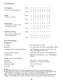
Allmänna data
Fönster: Röda och gröna lampor
Batteri: 9 V, 006P eller IEC 6F22 eller NEDA 1604
Indikator för låg batteriladdning: Indikatorn tänds inte när knappen
BATT trycks
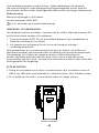
Batteriets användningstid: Cirka 20 timmar. (Alkaliskt batteri)
Miljö: Användning inomhus, högsta höjd över
havet: 2000 m (6561 fot)
Temperatur/Luftfuktighet:
Användning: 0 till 40 °C (32 till 104 °F), 10 till 70 %
relativ luftfuktighet
Förvaring: -10 till 60 °C (14 till 104 °F), 10 till 90 %
relativ luftfuktighet
Dimension: 130 x 64 x 38 mm (5,1 x 2,2 x 1,5 tum)
Vikt: 0,6 kg (1,2 pund)
-EMC: EN61326-1 Denna produkt uppfyller kraven enligt följande
direktiv i den Europeiska Gemenskapen: 89/336/EEC (Elektromagnetisk
kompatibilitet) och 73/23/EEC (Lågspänning) med tillägget 93/68/EEC (CE-
märkning). Elektriskt brus eller intensiva elektromagnetiska fält i närheten av
utrustningen kan störa mätkretsen. Mät- instrument kan även reagera på

48
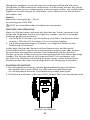
OPEN
Byte av batteri
icke önskvärda signaler som kan finnas i själva mätkretsen. Användaren
ska vara försiktig och vidta lämpliga försiktighetsåtgärder för att undvika
missvisande resultat under mätningar där elektroniska störningar förekommer.
Elektriska data
Maximal linjelängd: ca 300 meter
Anslutningstyper: RJ45, BNC
Får EJ användas på strömförande kretsar.
UNDERHÅLL OCH REPARATION
Om felaktig funktion misstänks i testaren ska du utföra följande moment för
att försöka isolera orsaken till problemet.
Tryck på knappen BATT för att kontrollera batteriet. Byt omedelbart ut 1.
batteriet om lampan inte tänds.
Läs igenom anvisningarna för att se om du har gjort misstag i 2.
användarproceduren.
Alla reparationer av instrumentet förutom byte av batteri ska utföras av
Fabriksauktoriserat Servicecenter eller av behörig instrumentservicepersonal.
Frontpanelen och höljet kan rengöras med en mild tvållösning och
vatten. Applicera sparsamt med en mjuk trasa och låt torka helt innan
instrumentet åter tas i bruk. Använd inte aromatiska kolväten eller klorerade
lösningsmedel för rengöring.
BYTE AV BATTERI
1. Stäng av instrumentet och skjut ut batteriluckan. Byt ut batteriet mot ett
NEDA typ 1604 eller motsvarande 9 V alkaliskt batteri. Sätt tillbaka luckan.
2. Ta ut batteriet när LAN-1 inte används under en längre period.

Please Recycle
Catalog•
Application notes•
Product specifications•
User manuals•
-
 1
1
-
 2
2
-
 3
3
-
 4
4
-
 5
5
-
 6
6
-
 7
7
-
 8
8
-
 9
9
-
 10
10
-
 11
11
-
 12
12
-
 13
13
-
 14
14
-
 15
15
-
 16
16
-
 17
17
-
 18
18
-
 19
19
-
 20
20
-
 21
21
-
 22
22
-
 23
23
-
 24
24
-
 25
25
-
 26
26
-
 27
27
-
 28
28
-
 29
29
-
 30
30
-
 31
31
-
 32
32
-
 33
33
-
 34
34
-
 35
35
-
 36
36
-
 37
37
-
 38
38
-
 39
39
-
 40
40
-
 41
41
-
 42
42
-
 43
43
-
 44
44
-
 45
45
-
 46
46
-
 47
47
-
 48
48
-
 49
49
-
 50
50


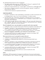
Amprobe AMLAN-1 Manual de usuario
- Categoría
- Medición
- Tipo
- Manual de usuario
- Este manual también es adecuado para
En otros idiomas
- français: Amprobe AMLAN-1 Manuel utilisateur
- italiano: Amprobe AMLAN-1 Manuale utente
- English: Amprobe AMLAN-1 User manual
- Deutsch: Amprobe AMLAN-1 Benutzerhandbuch
- svenska: Amprobe AMLAN-1 Användarmanual
Documentos relacionados
-
Amprobe LAN-1 Lan Cable Tester Manual de usuario
-
-
-
-
Amprobe VPC-30 Manual de usuario
-
-
-
Ampro Corporation THWD-3 Manual de usuario