
Edificio Genebre. Av. de Joan Carles I, 46-48
08908 L'Hospitalet de Llobregat. Barcelona (Spain)
[email protected] - www.genebre.es
GENEBRE S.A.
FECHA DE REVISIÓN: 16/03/2020 NUMERO DE REVISIÓN: 1
1
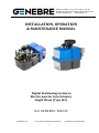
INSTALLATION, OPERATION
& MAINTENANCE MANUAL
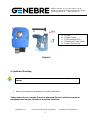
Digital Positioning System to
Electric quarter turn Actuator
Single Phase (Type J4C)
Ref. GENEBRE: 5810 00

Edificio Genebre. Av. de Joan Carles I, 46-48
08908 L'Hospitalet de Llobregat. Barcelona (Spain)
[email protected] - www.genebre.es
GENEBRE S.A.
FECHA DE REVISIÓN: 16/03/2020 NUMERO DE REVISIÓN: 1
2
INSTRUCTIONS FOR INSTALLATION, OPERATION & MAINTENANCE MANUAL
1. Product Description .............................................................................. 3
2. Technical Features & Data .................................................................. 3
3. Safety Instructions ................................................................................ 4
4. Transport and Storage ……………………………………………….. 4
5. Pre – Installation Inspection ………………………………………… 4
6. Positioner Mounting …………………………………………………… 5
7. External Electrical Connections ……………………………………. 12
8. Preliminary Test and Settings ………………………………………. 14
9. Maintenance ………………………………………………………….... 14

Edificio Genebre. Av. de Joan Carles I, 46-48
08908 L'Hospitalet de Llobregat. Barcelona (Spain)
[email protected] - www.genebre.es
GENEBRE S.A.
FECHA DE REVISIÓN: 16/03/2020 NUMERO DE REVISIÓN: 1
3
1. Product Description
The Digital Positioner is a fitting the electric actuator to convert the actuator in a self-
control valve positioner.
The Digital Positioner is a modulus with a microprocessor (CPU) which manages digitally
the analogical input and output and compare them with the position of the actuator to
establish an uniform relation.
The analogical inputs are sent to CPU where they are processed for his continuous
comparison with the position of the actuator, this allows to obtain a very high sensitivity
next to a very high repetitivity of the position (see characteristics).
The Digital Positioner in communication with the electronic system of the actuator
provides an integral management of the motion on the actuator.
Sign position input is converted to a digital numerical value and is continuously compared
with the position of potentiometer which is mechanically fitted to the valve shaft.
The programme in the microchip makes all the necessary calculations to determine which
way the motor should turn so that the potentiometer position and the valve corresponds
to the position, it keeps the motor in stopped position until it receives an input signal.
2. Technical Features & Data
General Features
Input Signal
4 – 20 mA / 0 – 10 V / 1 – 10 V
(NC or NO)
Output Signal
4 – 20 mA / 0 – 10 V / 1 – 10 V
Precision
3 % F.S.
Linearity
2 % F.S.
Hysteresis
3 % F.S.
Steps at 4-20 mA
Min. 150 steps 90º
Steps at 0-10 V
Min. 98 steps 90º
4-20 mA Input signal impedance
100 Ohm
0-10 V Input signal impedance
25 KOhm

Edificio Genebre. Av. de Joan Carles I, 46-48
08908 L'Hospitalet de Llobregat. Barcelona (Spain)
[email protected] - www.genebre.es
GENEBRE S.A.
FECHA DE REVISIÓN: 16/03/2020 NUMERO DE REVISIÓN: 1
4
3. Safety Instructions
The scope of this manual is to enable a competent user to install, operate, adjust and
inspect a Digital Positioning System to GE quarter turn electric actuator. These
instructions must be observed, otherwise a safe operation of the actuator is no longer
warranted.
4. Transport and Storage
• All products are packed in sturdy packing. During transport measures should
be adopted in order to prevent impacts, hits.
• Storage must be off the floor, covered with a sealed dust protector.
• While commissioning, Genebre, S.A. recommend a visual inspection in order to
detect any anomaly caused during the transport, handling or during the
storage.
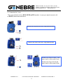
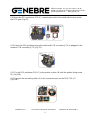
5. Pre-Installation Inspection
• Verify the product nameplate to insure correct model number, before installation or
use.
• Verify that the Kit is compounded from all parts (see Figure 1).
• If there is any discrepancy, please contact with our local distributor, or Genebre,
S.A., to solve that discrepancy.
As electric device, during electrical operation certain parts inevitably carry
lethal voltages and currents (ELECTRICAL RISKS). Work on the electrical
system or equipment must only be carried out by a skilled electrician himself or
by specially instructed personnel, in accordance with the applicable electrical
engineering rules, health and safety Directives and any other national legislation
applicable.
Under no circumstances should any modification or alteration be carried out
on the actuator as this could very well invalidate the conditions which the
device was designed.

Edificio Genebre. Av. de Joan Carles I, 46-48
08908 L'Hospitalet de Llobregat. Barcelona (Spain)
[email protected] - www.genebre.es
GENEBRE S.A.
FECHA DE REVISIÓN: 16/03/2020 NUMERO DE REVISIÓN: 1
5
Figure 1
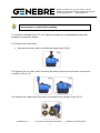
6. Positioner Mounting
• Reserve the space for maintenance routines and tasks.
Safety instructions on chapter 3 must be observed. Work on electrical system or
equipment must only be carried out by skilled electrician.
VERY IMPORTANT NOTICE: Follow these instructions carefully to avoid
damage.
A- 1 Cover
B- 1 Plastic column
C- 1 DPS positioner PCB
D- 2 Sheet metal Fixing screws
E- 1 Plastic Fixing screw

Edificio Genebre. Av. de Joan Carles I, 46-48
08908 L'Hospitalet de Llobregat. Barcelona (Spain)
[email protected] - www.genebre.es
GENEBRE S.A.
FECHA DE REVISIÓN: 16/03/2020 NUMERO DE REVISIÓN: 1
6
6.1 Preparing the Cover
The cover of the kit is for a GE-0. GE-05 y GE-1 models. In case you want to mount a kit
on GE-15, follow the instructions:
Remove the Cap and leave the o’ring inside the hole
Remove the Sleeve leave the o’ring inside the hole
Introduce the Sleeve in hole A and
press it until is fully inside (Fig.a).
Introduce the Cap in hole B and
press it until is fully inside (Fig.b).

Edificio Genebre. Av. de Joan Carles I, 46-48
08908 L'Hospitalet de Llobregat. Barcelona (Spain)
[email protected] - www.genebre.es
GENEBRE S.A.
FECHA DE REVISIÓN: 16/03/2020 NUMERO DE REVISIÓN: 1
7
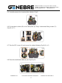
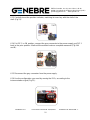
To convert a standard (ON-OFF) J4C electric actuator into a modulating function with
positioner, proceed as follows:
6.2 Remove the hand wheel:
• Remove the screw, which are fixing the hand wheel (Fig.2):
6.3 Remove the 6 screws, which are fixing the body to the cover of actuator and remove
carefully it (Fig.3 y 4):
6.4 Remove the cables (from the cover) connected to the actuator (Fig.5A,B,C):
VERY IMPORTANT NOTICE: The unit must be disconnected from any
electrical power or signal before installing.

Edificio Genebre. Av. de Joan Carles I, 46-48
08908 L'Hospitalet de Llobregat. Barcelona (Spain)
[email protected] - www.genebre.es
GENEBRE S.A.
FECHA DE REVISIÓN: 16/03/2020 NUMERO DE REVISIÓN: 1
8
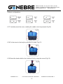
6.5 Carefully remove the visual position indicator (Fig.6):
6.6 Fix the plastic column (B) on the base plate, by using 2 sheet metal fixing screws (D).
(Fig.7A, B, C):
6.7 Take the DPS cover (A) and connect its cables following (Fig.8A, B y C):
6.8 Place the mentioned cables as per (Fig.9A y B):

Edificio Genebre. Av. de Joan Carles I, 46-48
08908 L'Hospitalet de Llobregat. Barcelona (Spain)
[email protected] - www.genebre.es
GENEBRE S.A.
FECHA DE REVISIÓN: 16/03/2020 NUMERO DE REVISIÓN: 1
9
6.9 Mount the DPS positioner PCB (C), matching the cleft of the shaft with the key inside
the DPS gear (Fig.10):
6.10 Press the DPS positioner along the shaft until PCB connector (JP3) is plugged in the
actuator PCB connector (JP2) (Fig.11):
6.11 Fix the DPS positioner PCB (C) to the plastic column (B) with the plastic fixing screw
(E) (Fig.12A):
6.12 Connect the remaining cable (A) to the connector base on the DPS PCB (C)
(Fig.12B):

Edificio Genebre. Av. de Joan Carles I, 46-48
08908 L'Hospitalet de Llobregat. Barcelona (Spain)
[email protected] - www.genebre.es
GENEBRE S.A.
FECHA DE REVISIÓN: 16/03/2020 NUMERO DE REVISIÓN: 1
10
6.13 Carefully insert the position indicator, matching its inner key with the cleft of the
shaft (Fig.13):
6.14 Put DIP 1 in ON position, connect the grey connector to the power supply, put DIP 1
back to the prior position. Wait until the actuator make a complete maneuver (Fig.14A
and B):
6.15 Disconnect the grey connector from the powe supply.
6.16 Use the configuration you need by moving the DIPs, according to the
instrumentation signal (Fig.15):

Edificio Genebre. Av. de Joan Carles I, 46-48
08908 L'Hospitalet de Llobregat. Barcelona (Spain)
[email protected] - www.genebre.es
GENEBRE S.A.
FECHA DE REVISIÓN: 16/03/2020 NUMERO DE REVISIÓN: 1
11
Different configurations:
6.17 Carefully mount the cover, minding the cables not to be pressed (Fig.16):
6.18 Fix the cover to the body by using the 6 screws (Fig.17):
6.19 Mount the hand whell on the shaft and fix it by using the screw (Fig.18):

Edificio Genebre. Av. de Joan Carles I, 46-48
08908 L'Hospitalet de Llobregat. Barcelona (Spain)
[email protected] - www.genebre.es
GENEBRE S.A.
FECHA DE REVISIÓN: 16/03/2020 NUMERO DE REVISIÓN: 1
12
6.20 Mount the 3 outer connectors together with its rubber joints and fix them to the
cover, by using the screws (Fig.19):
The unit is ready to work.
6.21 Outer Set-Up (only if necessary):
• B plug: Connect a cable between PIN 1 and PIN Earth (Fig.20).
• A plug: Connect it to the power supply.
• B plug: Disconnect the cable between PIN 1 and PIN Earth.
The actuator will make a complete maneuver.
7. External Electrical Connections
WARNING: Make all connections as shown on the wiring diagram affixed
to the new cover.

Edificio Genebre. Av. de Joan Carles I, 46-48
08908 L'Hospitalet de Llobregat. Barcelona (Spain)
[email protected] - www.genebre.es
GENEBRE S.A.
FECHA DE REVISIÓN: 16/03/2020 NUMERO DE REVISIÓN: 1
13
External Electric Wiring
A = Alimentación Eléctrica / Power supply plug
A = VCA 2 CABLES (Conector gris) / VAC 2 WIRES (Grey plug)
PIN 1 = Neutro // PIN2 = Fase = Alimentación Eléctrica / Power supply
A = VCC 2 CABLES (Conector gris) / VDC 2 WIRES (Grey plug)
PIN 1 = (-) Negativo // PIN 2 = (+) Positivo = Alimentación Eléctrica / Power supply
B = Señal de Instrumentación / Control Signal
PIN 1 = (-) Negativo // PIN 2 = (+) Positivo = Señal de Entrada / Input Signal
PIN 1 = (-) Negativo // PIN 3 = (+) Positivo = Señal de Salida / Output Signal
C = Contactos Auxiliares / Volt free contact plug
PIN 1 // PIN 2 = Cerrado / Closed
PIN 1 // PIN 3 = Abierto / Open

Edificio Genebre. Av. de Joan Carles I, 46-48
08908 L'Hospitalet de Llobregat. Barcelona (Spain)
[email protected] - www.genebre.es
GENEBRE S.A.
FECHA DE REVISIÓN: 16/03/2020 NUMERO DE REVISIÓN: 1
14
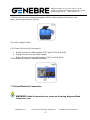
8. Preliminary Test and Settings
• It is recommended that only qualified electrical engineers be allowed to connect or
adjust these devices. Always ensure that the power supply is disconnected prior to
removing the top cover by disconnecting the DIN power input plug.
The LED status light provides visual communication between the actuator and the user
9. Maintenance
These actuators are free maintenance, but when conditions are more severe, more
frequent inspections may be advisable.
• Ensure valve actuator alignment.
• Insure wiring is insulated, connected and terminated properly.
• Insure all screws are present and tight.
• Insure conduit connections are installed properly and are dry.
• Verify declutch mechanism.
LED
Status
-
 1
1
-
 2
2
-
 3
3
-
 4
4
-
 5
5
-
 6
6
-
 7
7
-
 8
8
-
 9
9
-
 10
10
-
 11
11
-
 12
12
-
 13
13
-
 14
14


en otros idiomas
- English: Genebre 5810 Installation guide
Artículos relacionados


Otros documentos
-
UFESA DM35G El manual del propietario
-
Leotec LE-SW25 Guía del usuario
-
-
UFESA BS4790 El manual del propietario
-
-
Ksix BXSW14V Manual de usuario
-
 Ksix BXSW13G Manual de usuario
-
 Ksix BXBULB6011 Smart Bulb SmartLED Manual de usuario
-
Samsung DVD-E232A Manual de usuario

