KNOVA KN S-38W2 El manual del propietario
- Tipo
- El manual del propietario

KN S-38W2
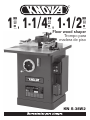
Floor wood shaper
1
”
, 1-1/4
”
, 1-1/2
”
Trompo para
madera de piso
(25.4 mm)
(31.8 mm)
(38.1 mm)

IDENTIFICATION ............................ 1
Table of contents ........................... 1
Product specicationts .................. 1
Control and features ...................... 2
SEP UP ............................................. 2
Piece inventory ............................. 2
Begginnig assembly ....................... 2
Spindle .......................................... 3
Table inserts .................................. 4
Extension wing ............................... 4
Fence assembly ............................. 4
PRODUCT SPECIFICATIONS
TABLE OF CONTENTS
IDENTIFICATION
1
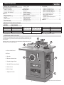
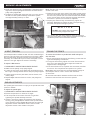
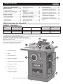
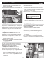
To help you understand the setup and operation instructions, we
recommend that you become familiar with the basic features of your
new shaper.
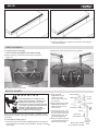
Please match up the list below with the letters in Figure 2 to identify
the shaper controls and features.
Fig. 2 Controls and Features
CONTROLS AND FEATURES
A. Cutterhead Guard
B. Fence
C. Spindle
D. Elevation Handwheel
E. Spindle Height Scale
F. ON/OFF Reversing Switch
G. Motor Cover
H. Miter Gauge
I. Magnetic Switch
All specication, dimensions and design characteristics shown in this catalogue are subject to change without notice.
Worktable with
extension wing: 30-1/2” x 28-1/4”
Spindle diameter: 1”, 1-1/4”, 1-1/2”
Router bit collets: 1/4” and 1/2”
MODEL KN S-38W2
A
BC
D
E
F
G
H
I
Motor: 3 H.P. 220 V. 60 Hz.
Spindle speeds:
7,000 and 9,000 R.P.M.
Fence size: 12” x 2-3/4”
Spindle travel: 3”
Overal dimensions:
31-1/2” x 26-3/4” x 44”
Insert opening: 120 and 62 mm.
Net weight: 195 kg.
Gross weight: 216 kg.
Safety guard .................................. 5
Hold-downs ................................... 6
OPERATION .................................... 6
Rotation ......................................... 6
Speed changes .............................. 6
Cutter installation .......................... 7
Spindle height ............................... 7
SERVICE ADJUSTMENTS ............. 7
Pulley alignment ........................... 7
V-Belt tension ............................... 8
Truing the fence ............................ 8
Gib adjustments ............................ 8
CLOSURE ........................................ 9
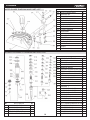
Cabinet/Table part list ................ 9
Cabinet/Table diagram ................. 10
Motor assembly part list ............... 11
Motor assembly diagram .............. 12
Fence diagram part list ................. 13
Miter guage diagram
and part list ................................... 14
Spindle assembly diagram
and part list ................................... 14
NOTES ............................................. 15

2
SET UP
BEGINNING ASSEMBLY
NOTICE
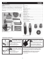
A full parts list and breakdown can be found toward the end of
this manual. For easier assembly, or to identify missing parts,
please refer to the detailed illustrations at the end of the manual.
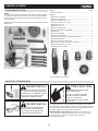
After all the parts have been removed from the carton, you
should have:
Box 1: Qty
Extension Wing ..................................................................... 1
Box 2:
• Miter gauge ....................................................................... 1
• Handle for handwheel ........................................................ 1
• Spindle1-1/2”.................................................................... 1
• Splinde 1-3/4” .................................................................. 1
• Router bit 1/2” .................................................................. 1
• Router bit 1/4” .................................................................. 1
• Safety guard ...................................................................... 1
• Safety guard shaft ............................................................. 1
• Hold downs ........................................................................ 4
• Hold down bars ................................................................. 2
• Hold down brackets ........................................................... 4
• Extension bracket w/lock knob ......................................... 1
• Lock handle ....................................................................... 1
• Guard extension bar .......................................................... 1
• Shaft mount bracket w/set screw ..................................... 1
• Fence lock handle .............................................................. 2
• Rear door panel knob ........................................................ 1
PIECE INVENTORY
Fig. 3. Parts inventory 1
Fig. 4 Parts inventory 2
Disconnect power from the machine
when performing any maintenance,
assembly or adjustments.
Failure to do this may result
in serious personal injury.
Wear safety glasses during the entire
assembly process.
Failure to comply may result
in serious personal injury.
Some metal parts may have sharp
edges on them after they are formed.
Please examine the edges of all
metal parts before handling them.
Failure to do so could result in injury.
Most of your 3HP heavy duty Shaper has been assembled at
the factory, but some parts must be assembled or installed
after delivery. We have organized the assembly process
into steps. Please follow along in the order presented here.
TOOLS REQUIRED: You will need a 12” to 18” long
straightedge, 12, 14, and 17mm open end wrenches,
4 and 8mm hex wrenches, and a Phillips and at
head screwdriver.
WARNING
WARNING
CAUTION

3
SEP UP
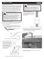
This 3HP shaper comes with1 3 1⁄2”, ⁄4”, & 1” interchangeable
spindles. Each spindle is sized to work efciently with different
sized cutters and spacers. The spindles must be inserted
correctly and remain securely locked in the machine in order
to produce quality work. When installing and changing spindles,
make sure the spindle seats snugly and that there is enough
drawbar threaded into the bottom of the spindle to safely secure
it in place.
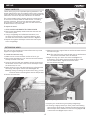
To install a spindle:
1. KEEP SHAPER DISCONNECTED FROM POWER!
2. Remove the hex nuts from the spindle and the drawbar nut
from the drawbar.
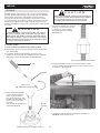
3. Thread the drawbar approximately 10-15 turns into
the bottom of the spindle. The drawbar has two threaded
ends. One of them remains exposed. See Figure 5.
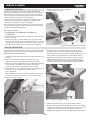
5. Thread the drawbar nut, tapered
side up, onto the bottom of the
drawbar until it stops below
the spindle housing cartridge.
See Figure 7.
6. Place the spindle wrench on top of the spindle, so it ts
over the head of the spindle. Place a 17mm wrench on the
drawbar nut. See Figure 8.
7. Hold the spindle in place and tighten the drawbar nut.
DO NOT use excessive force.
Incorrect assembly can allow the spindle and cutter to
y off the machine, which could cause injury or death.
Make certain the spindle is properly assembled before
operating the Shaper. If you are uncertain of any aspect
of this assembly, please review these instructions again
or contact our Customer Service.
Make sure the spindle keyway and pin are aligned
and properly seated before tightening the drawbar
nut. Improper assembly can create an unsafe
condition and possible injury to the operator.
WARNING
CAUTION
Fig. 5 Spindle and drawbar.
Fig. 8 Tightening the drawbar nut.
10-15 Turns
Drawbar
Spindle
Fig. 6 Inserting the spindle into place.
4. Place the spindle/drawbar
into the spindle cartridge
at the top of the table.
Line up the keyway on the
spindle with the locating pin
at the top of the spindle
cartridge.
You will feel the spindle seat
itself. See Figure 6.
Spindle
cartridge
Fig. 7 Nut threaded onto drawbar.
SPINDLE

4
SEP UP
inserts which give you four possible opening diameters in the
shaper table surface. Use the smallest opening that a particular
cutter will allow. This offers more support for the workpiece and
reduces the amount of chips that can fall into the machine.
The correct spindle opening will also allow any unused portion
of the cutter to remain below the table surface—increasing
operator protection. There are two aluminum table inserts
and one cast iron table insert. The cast iron table insert must
be ush with the top of the table.
To adjust the insert:
1. KEEP SHAPER DISCONNECTED FROM POWER!
2. Remove the three Phillips head screws that hold the cast
iron insert in place.
3. Using a straightedge and a athead screwdriver, turn
the barrel screw clockwise or counterclockwise to level
the steel cast insert with the table as shown in Figure 9.
4. Replace and tighten the Phillips head screws and inspect
with a straightedge.
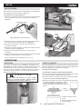
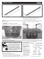
The cast iron wing extends your work surface area to provide
support for larger workpieces.
To install the extension wing:
1. Make sure the contact surfaces are free of dirt or grit.
2. Remove the three 3⁄8-16 x 11⁄4” hex bolts and lock washers
already mounted to the table.
3. Insert the hex bolts with lock washers through the wing and
thread them into the holes at the front of the shaper. Leave
the bolts loose, for now.
4. Raise the wing on one side and make sure it is ush with the
table edge, then tighten the rst bolt. See Figure 10.
Note: By raising or lowering the far end of the wing, you can
locate the center of the wing ush with the shaper table.
5. Secure the center bolt.
6. Make sure the wing edge is ush at the rst two bolts and that
the bolts are tight.
Note: The end of the wing at the last bolt may not be ush with
the surface of the table. Don’t be alarmed.
7. Adjust the wing up or down at the last bolt (Figure 11).
If necessary, use a clamp and some wood blocks to make
the two surfaces ush. Tighten the nal bolt when
the two surfaces are ush.
8. Inspect your results with a good-quality straightedge.
9. If the wing is slightly tilted up or down, place some masking
tape along the whole length, between the table and the wing.
Place the tape above the bolts to lower the wing (Figure 12)
or below the bolts (Figure 13) to raise it.
Fig. 9 Leveling table insert.
Fig. 10 Installing extension wing.
Fig. 11 Adjusting to ensure atness.
Steel
cast
insert
EXTENSION WING
TABLE INSERTS

5
SEP UP
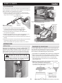
Fig. 12 Masking tape location for lowering wing.
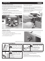
Fig. 14 Remove the cap screws. Fig. 15 Replace the fence lock levers.
Fig. 13 Masking tape location for raising wing.
10. Following adjustments, tighten the hex bolts in the sequence
they were installed.
All guards MUST be installed on your
shaper before operating it. Shapers are
dangerous machines that can quickly
cause serious injury if some kind of guard
is not used. To protect yourself, read and
follow the entire instruction manual
carefully and do additional research on
shop made guards and safety jigs.
FENCE ASSEMBLY
SAFETY GUARD
To install the fence assembly:
1. KEEP SHAPER DISCONNECTED FROM POWER!
2. Remove the cap screws with hex wrench as shown in
gure 14.
There are other methods to protect yourself, in addition to the
safety guard. However, some type of safety guard must be used
at all times.
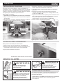
To assemble the safety guard:
1. Attach the shaft mount bracket (See Figure 16) to the back of
the table with the hex bolts and lock washers already mounted
to the table.
3. Replace the cap screws with fence lock levers
WARNING
2. Insert the shaft
(Figure 16) into the
bracket so the at
surface faces away from
the machine.
3. Slide the extension bracket
(Figure 16) through the
shaft and secure it with
the lock knob.
4. Using the two 5/16” -18 x
3/4” at head screws and
hex nuts, tightly secure the
extension bar to the main
guard. See Figure 16.
5. Attach the guard assembly
to the shaft assembly and
tighten the lock handle.
Extension bar
Main guard
Extension bracket
Shaft
Lock knob
Lock
handle
Set
screw
Shaft mount bracket
Fig 16. Guard assembly
Hex bolt &
lock washer

SEP UP
6
Hold-downs are used to hold the workpiece at on the table and
snug against the fence as shown in Figure 19.
To assemble the spring hold-downs:
1. Slide two hold-down brackets onto each of the hold-down bars
(one on the short arm, one on the long arm) as shown in
Figure 17.
2. Slide the long arm of the hold-down bars through the holes in
the cast iron fence brackets as shown in Figure 18.
3. Partially screw the 5⁄16”-18 x 3⁄8” setscrews into the
hold-down brackets.
4. Slide each hold-down between a hold down bracket and hold
down bar as shown in Figure 19.
5. Position the hold-downs according to the size of your
workpiece.
6. Tighten the setscrews in the fence brackets and the hold-down
brackets to x the position of the hold-downs.
Remove the hold-down assembly when not in use.
Your shaper is equipped with a FORWARD/ REVERSE switch.
See Figure 20. In many instances, it will be necessary to ip the
cutter over and reverse cutter rotation. Whenever possible,
mount the cutter so the board is milled on the bottom side (the
side away from the operator). This does a better job and it is
safer for the operator.
Always check the direction of cutter rotation
before any shaping operation. Cutters rotating
backwards will cause unsafe conditions.
Hold-down brackets
Hold-down
bart
Fig 17. Brackets on hold-down bar.
Fig 18. Inserting hold-down bar into fence bracket.
Fig 19. Use hold-downs from both sides.
Fig 20. Forward/reverse switch. Fig 21. Speed change belt positions.
7,000
9,000
Hold-down
bart Hold-downs
Fence
bracket Hold-down
brackets
OPERATIONS
ROTATION
CAUTION
The Model G1026 Shaper is equipped with a special high speed
V-belt. It is designed to withstand the vibration and sudden shock
loads associated with the operation of a shaper.
To change spindle speeds:
1. DISCONNECT SHAPER FROM POWER SOURCE!
2. Loosen the two motor mount bolts and slide the motor toward
the spindle assembly. DO NOT take the bolts out.
3. Move the V-belt to a sheave on the motor and spindle pulleys
to select the desired speed (See Figure 21.)
4. Slide the motor back into position and tighten the belt. When
the belt is properly tensioned, there should
be approximately 1⁄4” of deection in the
center of the belt when you press it with your
thumb.
5. Tighten the motor mount
bolts.
6. Spin the pulley to ensure
proper tracking.
SPEED CHANGES
HOLD-DOWNS

7
OPERATIONS
Your shaper operates at speeds of 7,000 and 10,000 RPM. 31/2”
or larger cutters must be operated at the slower speed. Always
use the largest spindle size possible, and never use a cutter bore
more than one size larger than the spindle size.
To install a cutter:
1. DISCONNECT SHAPER FROM POWER SOURCE!
2. Loosen the knurled lock knob and temporarily move the main
safety guard out of the way.
3. If needed, place an appropriate spacer or collar at the base of
the spindle for support.
To adjust the cutter height:
1. Loosen the spindle lock. See Figure 24.
2. Move the spindle up or down with the elevation handwheel
until the desired position is obtained.
3. Lock the spindle into position.
Improper pulley alignment sharply reduces the effectiveness of
power transmission and belt life expectancy.
To align the pulleys:
1. DISCONNECT SHAPER FROM POWER SOURCE!
2. Open the motor cover on the side of the shaper cabinet.
4. Place the cutter on the spindle. Make sure the rotation is
correct for your application.
5. Use spacers or collars to suit your particular application.
6. Place a spindle washer above the cutter and screw on the nut
and locknut as shown in Figure 22.
7. Tighten the nuts while holding the spindle stationary. Place a
spindle wrench on the notches at the top of the spindle for
leverage as shown in Figure 23.
8. Replace the safety guard.
CUTTER INSTALLATION
Fig 22. Cutter and fasteners. Fig 23. Tightening spindle nuts.
Fig 24. Spindle lock knob.
Lock nut
Nut
Cutter Collar
Spindle
washer
SPINDLE HEIGHT
SERVICE ADJUSTMENTS
Keep clothing rolled up and out of the
way of machinery and keep hair pulled
back.
Disconnect power to the machine
when performing any maintenance
or assembly.
Failure to do this may result in serious
personal injury.
Wear safety glasses during
the entire adjustment process.
Failure to comply may result
in serious personal injury.
WARNING
WARNING
WARNING
PULLEY ALIGNMENT

8
SERVICE ADJUSTMENTS
3. Check the alignment with a straightedge. If the pulleys are in
alignment, the straightedge should touch two sides of each
pulley evenly. Figure 25.
4. If pulleys are parallel with each other, but not in line, remove
the belt from the spindle assembly and slide the spindle
cartridge assembly either up or down.
Note: The side cover can be removed from the shaper to improve
access to the motor.
5. Inspect for tilt on the motor pulley. If the pulley is tilted, loosen
the four bolts holding the motor onto the motor plate. Wiggle
the motor into position. (Do not loosen the bolts that hold the
motor onto the motor mount; this plate is preset with blocks
that hold it in position and it cannot be adjusted.)
6. Inspect your results. If they are satisfactory, tighten all
fasteners. Remember to tighten the bolt in the split housing
that holds the spindle cartridge in position.
You should be able to deect the belt 1⁄4” with moderate nger
pressure. This may seem tight compared to most other V-Belts,
but since the belt is small and runs fast, this much tension is
necessary. The V-Belt will slip if too loose and squeal or cause
vibration if too tight. Adjust the tension if necessary.
To adjust V-Belt tension:
1. DISCONNECT SHAPER FROM POWER SOURCE!
2. Make sure the pulleys are properly aligned.
3. Loosen the two motor mount plate bolts and slide the motor
left or right to modify the belt tension. Keep the pulleys aligned.
4. Tighten the motor mount plate bolts, test the tension, and
check pulleys.
5. Repeat Steps 3-4 until tension is correct, and pulleys are
aligned.
The spindle gibs ensure there is no play in the spindle that could
cause it to wobble.
To adjust the spindle gibs:
1. DISCONNECT SHAPER FROM POWER SOURCE!
2. Elevate the spindle to its maximum 3” height.
3. Test the spindle for movement from left to right after
tightening the spindle assembly lock knob.
4. If there is movement, adjust the gib against the elevation
housing, using the adjustment screws at the top and bottom
of the elevation housing. Figure 26 shows the two upper gib
adjustment screws and locknuts. One of the two lower
adjustment screws is also visible in the photo.
To ensure that the fence is parallel with itself and square
with the table:
1. Ensure that the bolts through the wood facing on each side are
tight and adequately countersunk.
2. To align the wood facing, adjust one or both fence halves so
they are in close alignment. Micro-adjust and check the
alignment with a straightedge.
3. If the wood fences are not coplanar with each other,resurface
as one unit. You can perform this operation on a jointer.
Note: Make sure the screws are countersunk deep enough so
the workpiece will not come in contact with the heads
of the screws.
Or use electrical washers between the fence and the fence
bracket to shim the fence into the correct position.
7. You can also align the motor pulley by raising or lowering it
along the motor shaft. Loosen the two setscrews and tap into
the desired position with a dead blow hammer.
DO NOT over-tighten. Cast iron threads
are more easily stripped than steel.
NOTICE
V-BELT TENSION TRUING THE FENCE
GIB ADJUSTMENTS
Fig 25. Inspecting pulley alignment.
Fig 26. Gib adjustment screws.
Upper gip
adj. screws
Lower gip
adj. screw

9
SERVICE ADJUSTMENTS
5. Loosen the four 12mm locknuts and remove the slack between
the elevation housing and spindle cartridge slide by tightening
the four 5/16” setscrews with a 4mm hex wrench. Alternate
between the upper and lower adjustments to ensure
consistent tightness. Failure to do so may cause disappointing
results. DO NOT over-tighten the gib. Overtightening will
restrict spindle movement.
6. Loosen the spindle assembly lock knob and raise or lower the
spindle to check for free movement.
The lock knob keeps the spindle in a xed position
during shaper operation. Do not over-tighten
the lock knob. A snug t is all that’s needed to keep
the spindle from moving during shaper use.
NOTICE
Since there is an unbalanced weight distribution on the cartridge
slide, you may have to perform a number of adjustments before
you nd the ideal location. Don’t get discouraged; it may take a
few tries to get it right.
CLOSURE
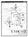
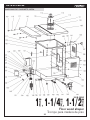
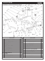
CABINET / TABLE PART LIST
Description Qty.
No.
101 CABINET STAND 1
102 SIDE DOOR 1
103 SWITCH BRACKET 1
104 SWITCE BRACKET 1
105 GPHILLIPS HEAD SCREW M5 x 10 10
106 CABINET IEAR CONER 1
107 KNOB 1
108 RUBBER FEET 4
109 TABLE 1
110 TABLE INSERT 1
111 PAN HEAD SCREW 3
112 FLAT HEAD SCREW M5 x 20 3
113 TABLE INSERT 1
114 TABLE COVER 1
115 PIN 2
116 EXTENSION WING 1
117 FLAT WASHER 10 7
118 LOCK WASHER M10 7
119 CAP SCREW M10 x 30 3
120 HEX BOLT M10*20 4
121 SCALE 1
122 PHILLIPS HEAD SCREW M4 x 8 6
123 MAGNITIC STARTER 1
Description Qty.
No.
124 PHILLIPS HEAD SCREW M5 x 12 1
125 LOCK WASHER M5 1
126 FLAT WASHER 5 1
127 SERRATED SPACER 5 1
128 FWD/REV SWITCH SELECTOR 1
129 SWITCH BOX 1 1
130 SWITCH BOX 2 1
131 HEX NUT M 5 2
132 PHILLIPS HEAD SEREW M5 x 6 8
133 HANGER 1
134 STRAIN RELIEF 4
135 PUWER LINE 1
136 PHILLIPS HEAD SEREW M4 x 6 4
137 RUBBER BUSHING 1
138 HOLD DOWN 1
139 LEVELING FOOT 2
140 HEX NUT M 8 4
141 FLAT WASHER 8 8
142 LOCK WASHER M8 3
143 CAP SCREW M8 x 55 3
144 TROLLEY WHEEL 1
145 UNIWERSAL PULLEY 2
146 HEX NUT M8 x 50 2

CABINET / TABLE DIAGRAM
CLOSURE
10
Floor wood shaper
1
”
, 1-1/4
”
, 1-1/2
”
Trompo para madera de piso
(25.4 mm)
(31.8 mm)
(38.1 mm)
KN S-38W2

CLOSURE
11
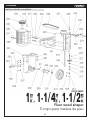
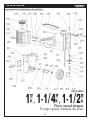
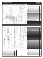
Description Qty.
No.
201 ELEVATION HOUSING 1
202 LOCK 1
203 HANDWHEEL 1
204 FLAT WASHER Ø6 1
205 CAP SCREW M6 x 16 1
206 SET SCREW M8 x 35 4
207 NUT M 8 4
208 WORT SHAFT 1
209 SHAFT MOUNT 1
210 SLEEVE 1
211 KEY 5 x 5 x 15 1
213 HANDWHEEL 1
215 HANDLE 1
216 SPINDLE SLIDE 1
217 LOCK NUT M 12 1
218 FLAT WASHER Ø12 1
219 BEARING 51101 1
220 GEAR 1
221 ELEVATION LEAD SCREW 1
222 KEY 4 x 4 x 16 1
223 POINTER MOUNT 1
224 POINTER 1
Description Qty.
No.
225 FLAT WASHER Ø6 2
226 HEX BOLT M8 x 12 2
227 FLAT WASHER Ø8 1
228 BELT 1
229 BOTTON HEAD SCREW M8 x 40 1
230 FLAT WASHER Ø10 2
231 LOCK NUT M10 x 35 2
232 KEY 8 x 5 x 32 1
233 SET SCREW M8 x 10 1
234 MOTOR PULLY 1
235 MOTOR 1
236 FLAT WASHER Ø8 5
237 HEX BOLT M8 x 25 4
238 LOCK WASHER Ø8 4
239 LOCK WASHER Ø10 8
240 CAP SCREW M10 x 45 4
241 MOTOR MOUNT PLATE 1
242 LOCK WASHER Ø6 5
243 HEX BOLT M6 x 16 5
244 SET SCREW M6 x 6 2
245 GIB 1
MOTOR ASSEMBLY PART LIST

MOTOR ASSEMBLY DIAGRAM
CLOSURE
12
Floor wood shaper
1
”
, 1-1/4
”
, 1-1/2
”
Trompo para madera de piso
(25.4 mm)
(31.8 mm)
(38.1 mm)
KN S-38W2

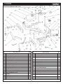
FENCE DIAGRAM PART LIST
13
CLOSURE
Description Qty.
No. Description Qty.
No.
401 FENCE HOUSING 1
402 RIGHT FENCE MOUNT 1
403 SET SCREW M6 x 10 10
404 LOCK HANDLE M8 x 25 2
405 FIAT WASHER 8
406 CAP SCREW M8 x 16 2
407 BLOCK 2
408 ADJUSTMENT SCREW 2
409 KNOB 2
410 DUST ADAPTER 1
411 SHAFT MOUNT 1
412 SET SCREW M8 x 10 1
413 PHILLIPS HEAD SCREW M5 x 10 4
414 CAP SCREW M10 x 25 2
415 SHAFT 1
416 KNOB M8 x 18 1
417 EXTENSION BRACKET 1
418 FLAT WASHER 8 3
419 HEX BOLT M8 x 16 1
420 FLAT WASHET 12 1
421 HANDLE PEG 1
422 LOCK HANDLE R80 2
423 LOCK HANDLE 2
424 PHILLIPS HEAD SCREW M6 x 16 2
425 EXTENSION BAR 1
426 GUARD 1
427 CAP SCREW M6 x 16 2
428 LEFT FENCE MOUNT 1
429 FENCE 2
430 HOLDOWN BAR 2
431 BRACKET HOLD-DOWN 4
432 SET SCREW M8 x 16 4
433 HOLD-DOWN 4
434 PHILLIPS HEAD SCREW M8 x 20 4
435 FLAT WASHER 8 4

MITER GUAGE DIAGRAM AND PART LIST
14
CLOSURE
Description Qty.
No.
501 MITER GAUGE BODY 1
502 HEX NUT M4 3
503
PHILLIPS HEAD SCREW M4 x 20
3
504 PIVOT PIN 1
505 FIAT HEAD SCREW M6 x 50 1
506
PHILLIPS HEAD SCREW M4 x 10
2
507 LOCK WASHER M4 2
508 FIAT WASHER 4 3
509 T-SOLT WASHER 1
510 MITER BAR 1
511 STOP PIN 1
512
PHILLIPS HEAD SCREW M4 x 12
1
513 POINTER 1
514 STOP BLOCK 1
515 FIAT WASHER 6 1
516 HANDLE 1
517 MITER 1
518 RIVEY 2 x 6 3
SPINDLE ASSEMBLY DIAGRAM AND PART LIST
Description Qty.
No.
328 1/2” RUB COLLAR 9.5 2
329 1/2” RUB COLLAR 6.5 2
330 1/2” RUB COLLAR 5 1
331 KEYED SAFETY NUT 1
332 SPECIAL SPINDLE NUT 1/2” 1
Description Qty.
No.
301 SPINDLE CARTRIDGE 1
302 HOUSING 1
303 FLANGE 1
304 SPINDLE PULLEY 1
305 BEARING 6006 Ø 2
306
EXTERNAL RETAINING RING Ø30
1
307
EXTERNAL RETAINING RING Ø
68 1
308
INTERNAL RETAINING RING Ø55
2
309 KEY 5 x 15 1
310
PHILLIPS HEAD SCREW M4x12
3
311 LOCK WASHER Ø4 3
312 NUT 2
313 DRAW BAR 1
314 SPINDLE 1” 1
315 1” SPINDLE WASHER H=30 1
316 1” SPINDLE WASHER H=20 1
317 1” SPINDLE WASHER H=10 2
318 DRAW NUT 1
319 SPINDLE NUT 1” 2
320 SPINDLE 3/4” 1
321 3/4” SPINDLE WASHER H=10 2
322 3/4” SPINDLE WASHER H=20 2
323 SPINDLE NUT 3/4” 2
324 ROUTER BIT 1/2” 1
325 ROUTER BIT NUT 1
326 ROUTER BIT 1/4” 1
327 CUTTER SPINDLE 1/2” 1

NOTES
15

IDENTIFICACION .......................... 16
Tabla de contenido ....................... 16
Especicaciones del producto ...... 16
Controles y caracteristicas .......... 16
PUESTA A PUNTO ........................ 17
Inventario de piezas .................... 17
Inicio de ensamblado ................... 17
Porta-herramientas ..................... 18
Inserto de mesa ........................... 19
Ala de extensión ........................... 19
Valla ............................................. 20
ESPECIFICACIONES DEL PRODUCTO
TABLA DE CONTENIDO
Para ayudarle a entender las instrucciones de puesta a punto y
operación, recomendamos que se familiarice con las características
básicas de su trompo nuevo.
Relacione la lista que se encuentra a continuación
con las letras en la Figura. 2 para identicar
los controles y características del trompo.
Fig. 2 Controles y características.
CONTROLES Y CARACTERISTICAS
A. Guarda de cortador
B. Valla
C. Porta-herramienta
D. Manivela de elevación
E. Escala de altura de porta-herramienta
F. Interruptor reversible
G. Cubierta de motor
H. Calibrador de inglete
I. Interruptor magnético
Todas las especicaciones, dimensiones y características de diseño que se muestran en este manual están sujetas a cambios sin previo aviso.
Mesa de trabajo
con extención: 775 x 718 mm.
Diámetro de husillos:
2
5.4, 31.8, 38.1 mm.
Boquillas para brocas:
6.3 y 12.7 mm.
MODELO KN S-38W2
A
BC
D
E
F
G
H
I
Motor: 3 H.P. 220 V. 60 Hz.
Velocidades: 7,000 y 9,000 R.P.M.
Dimensión de valla:
304.8 x 69.9 mm.
Carrera del husillo:
76 mm.
Dimen. de la máquina:
800 x 680 x 1,120 mm.
Abertura de inserción:
120, 62 mm.
Peso neto: 195 kg.
Peso bruto: 216 kg.
Guarda de protección .................. 20
Sujetadores ................................. 21
OPERACION .................................. 21
Rotación ....................................... 21
Cambio de velocidades ................ 21
Instalación del cortador ................ 22
Altura del porta-herramientas....... 22
SERVICIO Y AJUSTES ................. 22
Alineación de las poleas .............. 22
Tensión de la banda ..................... 23
Exactitud de la valla ..................... 23
Ajuste del riel ............................... 23
LISTA DE PARTES ......................... 24
Lista de partes del gabinete/mesa
... 24
Diagrama del gabinete/mesa ....... 25
Lista de partes del ensablaje de motor
..... 26
Diagrama del ensablaje de motor
...... 27
Diagrama y lista de partes de la valla
... 28
Diagrama y lista de partes
del calibrador de ingletes ............. 29
Diagrama y lista de partes del
ensamblaje del porta-herramientas
.... 29
NOTAS ........................................... 30
16
IDENTIFICACION

17
PUESTA A PUNTO
INICIO DEL ENSAMBLADO
NOTA
Al nal de este manual encontrará una lista de partes completa
con despiece. Para un ensamblado más fácil, o para identicar
partes faltantes, reérase a las ilustraciones detalladas al nal
de este manual.
Después de que todas las piezas han sido retiradas de las cajas,
debe tener:
Caja 1: Cant.
• Ala de extensión ................................................................ 1
Caja 2:
• Calibrador de inglete ......................................................... 1
• Manija de la manivela ........................................................ 1
• Porta-herramienta de 1-1/2”............................................. 1
• Porta-herramienta de 1-3/4” ............................................ 1
• Adaptador de 1/2” ............................................................ 1
• Adaptador de 1/4” ............................................................ 1
• Guarda de seguridad ......................................................... 1
• Flecha de guarda de seguridad ......................................... 1
• Sujetadores ....................................................................... 4
• Barras de sujetador ........................................................... 2
• Soportes de sujetador ....................................................... 4
• Soporte de extensión con perilla aseguradora .................. 1
• Manija aseguradora ........................................................... 1
• Barra de extensión de la gurda .......................................... 1
• Soporte de montaje de echa con tornillo ......................... 1
• Manija aseguradora de valla .............................................. 2
• Perilla de puerta trasera .................................................... 1
INVENTARIO DE PIEZAS
Fig. 3. Inventario de piezas 1.
Fig. 4 Inventario de piezas 2.
Desconecte la corriente eléctrica de
la máquina cuando realice cualquier
mantenimiento, ensamblado o ajuste.
Si no lo hace así, puede resultar
en lesiones personales serias.
Use lentes de seguridad durante
todo el proceso de ensamblado.
Si no lo hace así, puede resultar
en lesiones personales serias..
Algunas piezas de metal pueden
tener bordes losos.
Por favor, examine los bordes
de todas las piezas metálicas
antes de manipularlas.
Si no lo hace así puede resultar
en lesiones.
La mayor parte de su trompo ha sido ensamblado en la fábrica,
pero algunas piezas se deben ensamblar o instalar después de la
entrega. Hemos organizado el proceso de ensamblado en pasos.
Por favor, sígalos en el orden aquí presentado.
HERRAMIENTA REQUERIDA: Necesitará una regla de 12”
a 18” (30 a 45 cm) de largo, llaves de 12, 14 y 17 mm, llaves
hexagonales de 4 y 8 mm, un desarmador Phillips y
un desarmador plano
ADVERTENCIA
ADVERTENCIA
PRECAUCION

PUESTA A PUNTO
Este trompo cuenta con porta-herramientas intercambiables de
1”, 1-1/4” y 1-1/2”. Cada porta-herramienta está dimensionado
para trabajar ecientemente con cortadores y espaciadores de
diferentes medidas. Los porta-herramientas deben insertarse
correctamente y permanecer rmemente asegurados en la
máquina para producir trabajos de calidad, asegúrese de que el
porta-herramienta asiente de forma ajustada y de que haya
suciente varilla roscada en la parte inferior del porta-herramienta
para asegurarlo de forma segura en su lugar. 5. Atornille la tuerca de varilla,
con el extremo cónico hacia arriba,
en la parte inferior de la varilla hasta
que se detenga debajo de la carcaza
del cartucho de porta-herramienta.
Vea la Figura 7.
6. Coloque la llave de porta-herramienta en la parte superior del
porta-herramienta, de manera que se asiente en la parte su
perior del porta-herramienta. Coloque una llave de 17 mm
en la tuerca de varilla. Vea la Figura 8.
7. Sujete el porta-herramienta y apriete la tuerca de varilla.
NO use fuerza excesiva.
Un ensamblado incorrecto puede ocasionar que el
porta-herramienta y el cortador sea expulsado de la
máquina, lo que puede causar lesiones o la muerte.
Asegúrese de que el porta-herramienta está
ensamblado adecuadamente antes de operar el trompo.
Si no está seguro en cualquier parte de este
ensamblaje, por favor revise éstas instrucciones o
póngase en contacto con el Centro de Servicio.
Asegúrese de que la muesca del porta-herramienta
y la espiga estén alineados y debidamente
asentados antes de apretar la tuerca de varilla.
Un ensamblado incorrecto puede generar una
condición insegura y una posible lesión al operador.
ADVERTENCIA
PRECAUCION
Fig. 5 Porta-herramienta y varilla.
Fig. 8 Apretar la tuerca de varilla.
10 a 15 giros
Varilla
Porta-herramienta
Fig. 6 Inserción del porta-herramienta en su lugar.
4. Coloque el porta-herramienta
y varilla en el cartucho de
porta-herramienta en la parte
superior de la mesa. Alinee la
muesca en el porta-herramienta
con la espiga en la parte
superior del cartucho de
porta-herramienta. Debe sentir
que el porta-herramienta se
asienta a sí mismo.
Vea la Figura 6.
Cartucho de
porta-herramienta
Fig. 7 Tuerca atornillada en la varilla.
PORTA-HERRAMIENTA
Para instalar un porta-herramienta::
1. ¡DESCONECTE LA CORRIENTE ELÉCTRICA DE LA MÁQUINA!
2. Retire las tuercas hexagonales del porta-herramientas
y la tuerca de la varilla.
3. Atornille la varilla de 10 a 15 giros en la parte inferior del
porta-herramienta. La varilla tiene dos extremos
roscados. Uno de ellos permanece expuesto.
Vea la Figura 5.
18

19
PUESTA A PUNTO
Los insertos le proporcionan cuatro posibles diámetros de
abertura en la supercie de la mesa del trompo. Use el diámetro
menor de abertura que permita un cortador. Esto le ofrece un
mayor soporte para la pieza de trabajo y reduce la cantidad de
residuos que puedan caer dentro de la máquina.
La abertura correcta también permitirá que cualquier parte no
usada del cortador permanezca debajo de la supercie de
la mesa, aumentando la protección al operador.
Hay dos insertos de mesa de aluminio y un inserto de mesa de
hierro fundido. El inserto de mesa de hierro fundido debe estar
a nivel con la supercie de la mesa.
Para ajustar el inserto:
1. ¡DESCONECTE LA CORRIENTE ELÉCTRICA DE
LA MÁQUINA!
2. Retire los tres tornillos Phillips que sujetan el inserto de mesa
de hierro fundido.
3. Usando una regla y un desarmador plano, gire los tornillos
de barril en el sentido de las manecillas del reloj o en sentido
contrario para nivelar el inserto de mesa de acero fundido con
la supercie de las mesa como se muestra en la Figura 9.
6. Asegúrese de que el borde del ala está nivelado en los
primeros dos tornillos y que los tornillos estén apretados.
Nota: El extremo del ala en el último tornillo puede ser que no
esté nivelado con la supercie de la mesa. No se alarme.
7. Ajuste el ala hacia arriba o hacia abajo en el último tornillo
(Figura 11). Si 3es necesario, use una prensa y algunos
bloques de madera para nivelar las dos supercies. Apriete
el tornillo nal cuando las dos supercies estén niveladas.
8. Revise los resultados con una regla de buena calidad.
9. Si el ala está ligeramente inclinada hacia arriba o hacia abajo,
coloque cinta adhesiva en todo lo largo entre la mesa y el ala.
Coloque la cinta arriba de los tornillos para bajar el ala
(Figura 12) o debajo de los tornillos (Figura 13) para elevarla.
Fig. 9 Nivelación del inserto de mesa.
Fig. 10. Instalación del ala de extensión.
Fig. 11 Ajuste para asegurar el nivel.
Inserto
de acero
fundido
ALA DE EXTENSION
INSERTOS DE MESA 4. Coloque y apriete los tornillos Phillips
y verique con una regla.
El ala de hierro fundido extiende el área de supercie de trabajo
para proporcionar soporte para piezas de trabajo más grandes.
Para instalar el ala de extensión:
1. Verique que las supercies de contacto estén libres de polvo
o arena.
2. Retire los tres tornillos hexagonales 3/8-16 x 1-1/4” y
roldanas de presión previamente montados en la mesa.
3. Inserte los tornillos hexagonales con las roldanas de presión a
través del ala y atorníllelos en los oricios al frente de
la máquina. No apriete los tornillos en este momento.
4. Suba el ala en un lado y asegúrese de que esté nivelada con el
borde de la mesa, luego apriete el primer tornillo.
Vea la Figura 10.
Nota: Subiendo o bajando el extremo nal del ala, se puede
colocar el centro del ala nivelado con la mesa del trompo.
5. Asegure el tornillo central.

PUESTA A PUNTO
Fig. 12 Colocación de cinta adhesiva para bajar el ala.
Fig. 14 Retiro de los tornillos. Fig. 15 Remplace las palancas aseguradoras de valla.
Fig. 13 Colocación de cinta adhesiva para subir el ala.
10. Como ajustes nales, apriete los tornillos hexagonales en la
misma secuencia en que fueron instalados.
Todas las guardas deben estar instala-
das en su trompo antes de operarlo. Los
trompos son máquinas peligrosas que
en un instante pueden causar lesiones
graves si alguna guarda no está en su
lugar. Para protegerse a usted mismo,
lea cuidadosamente y siga el manual de
instrucciones en su totalidad, además de
investigar acerca de guardas fabricadas
y sujetadores de seguridad.
VALLA
GUARDA DE PROTECCION
Para instalar la valla:
1. ¡DESCONECTE LA CORRIENTE ELÉCTRICA DE
LA MÁQUINA!
2. Retire los tornillos con una llave hexagonal como se muestra
en la Figura 14.
Existen otros métodos para protegerse, además de la guarda de
seguridad. Sin embargo, algunos tipos de guardas de seguridad
se deben usar todo el tiempo.
Para ensamblar la guarda de seguridad:
1. Una el soporte de la echa de montaje (vea la Figura 16) a
la parte posterior de la mesa con los tornillos hexagonales
y roldanas de presión previamente montados en la mesa.
3. Remplace los tornillos con las palancas aseguradoras
de valla
ADVERTENCIA
2. Inserte la echa (Figura
16) en el soporte con la
supercie plana apuntando
lejos de la máquina.
3. Deslice el soporte de
extensión (Figura 16) a
través de la echa y
asegúrela con la perilla
aseguradora.
4. Usando los dos tornillos
5/16”-18X3/4” y las
tuercas hexagonales, je
rmemente la barra de
extensión a la guarda
principal. Vea la Figura 16.
5. Una el ensamblado de
guarda a la echa
ensamblada y apriete la
manija aseguradora.
Barra de extensión
Guarda
principal
Soporte de
extensión
Flecha
Perilla
aseguradora
Manija
aseguradora
Tornillo
de ajuste
Soporte de
montaje de echa
Fig 16. Ensamblado de la guarda
Tornillo
hexagonal
y roldana
de presión
20

PUESTA A PUNTO
21
Los sujetadores se usan para mantener la pieza plana sobre la
mesa y ajustada contra la valla como se muestra en la Figura 19.
Para ensamblar los sujetadores de resorte:
1. Deslice los dos soportes de sujetador en cada una de las
barras de sujetador (uno en el brazo corto y uno en el brazo
largo) como se muestra en la Figura 17.
Su trompo está equipado con un interruptor HACIA ADELANTE/
REVERSA. Vea la Figura 20. En muchas ocasiones, será
necesario dar la vuelta al cortador y revertir el giro del cortador.
Siempre que sea posible, monte el cortador de manera que la
tabla trabaje en el lado inferior (el lado alejado del operador).
Esto hace un mejor trabajo y es más seguro para el operador.
Verique siempre la dirección de rotación del cortador
antes de cualquier operación. Los cortadores girando
hacia atrás causarán condiciones inseguras.
Soportes de sujetador
Barra de
sujetador
Fig 17. Soportes en
las barras de sujetador.
Fig 18. Inserción de las barras sujetadores
en el soporte de valla.
Fig 19. Uso de sujetadores en ambos lados.
Fig 20. Interruptor hacia adelante/reversa.
Fig 21. Posiciones de la banda para cambio de velocidad.
7,000
9,000
Barra de
sujetador Sujetadores
Soporte
de valla Soportes de
sujetador
OPERACION
ROTACION
PRECAUCIÓN
El modelo KN S-38W2 está equipado con una banda especial de
alta velocidad. Está diseñada para soportar la vibración y al cargas
repentinas de choque asociadas a la operación de un trompo.
Para cambiar la velocidad del porta-herramientas:
1. ¡DESCONECTE LA CORRIENTE ELÉCTRICA DE LA MÁQUINA!
2.
Aoje los dos tornillos de montaje del motor y deslice el motor
hacia el ensamblado de porta-herramientas. NO retire los tornillos.
3. Mueva la banda a una polea del motor y a una polea del
porta-herramientas para seleccionar la velocidad deseada
(Vea la Figura 21)
4. Deslice el motor de regreso a su posición y ajusta la banda.
Cuando la banda tiene la tensión correcta,
debe haber una deexión aproximada de
1/4” (6 mm) en el centro de la banda cuando
la presione con el dedo pulgar.
5. Apriete los tornillos
del motor.
6. Gire la polea para
asegurarse de una
tracción adecuada.
CAMBIOS DE VELOCIDAD
SUJETADORES
2. Deslice el brazo largo de las barras de sujetador
a través de los oricios en los soportes de valla de
hierro fundido como se muestra en la Figura 18.
3. Atornille parcialmente los tornillos 5/16”-18X3/8” en
los soportes de sujetador.
4. Deslice cada sujetador entre un soporte de sujetador y una
barra de sujetador como se muestra en la Figura 19.
5. Coloque los sujetadores de acuerdo al tamaño de la pieza de
trabajo.
6. Apriete los tornillos en los soportes de valla y los soportes de
sujetador para jar la posición de los sujetadores.
Retire el ensamblado de sujetadores cuando no se utilicen.

22
OPERACION
Su trompo opera a velocidades de 7,000 y 9,000 RPM. Los
cortadores de 3-1/2” o más grandes se deben operar a la velocidad
más baja. Use siempre la medida mayor de porta-herramientas
posible, y nunca use un oricio del cortador más de una medida
más grande que la medida del porta-herramienta.
Para instalar un cortador:
1.
¡DESCONECTE LA CORRIENTE ELÉCTRICA DE LA MÁQUINA!
2. Aoje la perilla aseguradora y retire temporalmente la guarda
de seguridad.
3. Si es necesario, coloque un espaciador adecuado o collarín en
la base del porta-herramienta para tener soporte.
Para ajustar la altura del porta-herramienta:
1. Aoje el seguro de porta-herramienta. Vea la Figura 24.
2. Mueva el porte-herramienta hacia arriba o hacia abajo con la
manivela de elevación hasta obtener la altura deseada.
3. Fije el porta-herramienta en posición.
Una alineación de poleas incorrecta reduce signicativamente
la transmisión de poder y el periodo de vida de la banda.
Para alinear las poleas:
1.
¡DESCONECTE LA CORRIENTE ELÉCTRICA DE LA MÁQUINA!
2. Abra la cubierta del motor en el costado del gabinete
de la máquina.
INSTALACIÓN DEL CORTADOR
Fig 22. Cortador y seguros. Fig 23. Apretar las tuercas del porta-herramienta.
Fig 24. Perilla aseguradora de porta-herramienta.
Tuerca de
seguridad
Tuerca
Cortador Espaciador
Roldana de
porta-herramienta
ALTURA DEL PORTA-HERRAMIENTAS
SERVICIO Y AJUSTES
Mantenga las mangas largas
enrolladas y el cabello largo
sujeto hacia atrás.
Desconecte la corriente eléctrica de
la máquina cuando realice cualquier
mantenimiento o ensamblado.
Si no lo hace así, puede resultar
en lesiones personales serias.
Use lentes de seguridad durante
todo el proceso de ajuste.
Si no lo hace así, puede resultar
en lesiones personales serias.
ALINEACIÓN DE LAS POLEAS
4. Coloque el cortador en el porta-herramienta. Asegúrese de
que la rotación es correcta para su aplicación.
5. Use espaciadores o collarines para ajustar a su aplicación
particular.
6. Coloque una roldana de porta-herramienta encime del
cortador y atornille la tuerca y tuerca de seguridad como se
muestra en la Figura 22.
7. Apriete las tuercas mientras sujeta el porta-herramienta en su
lugar, coloque una llave de porta-herramienta en la muesca
en la parte superior del porta-herramienta para
apalancamiento como se muestra en la Figura 23.
8. Vuelva a colocar la guarda de seguridad
ADVERTENCIA
ADVERTENCIA
ADVERTENCIA

23
SERVICIO Y AJUSTES
3. Verique la alineación con una regla. Si las poleas están
alineadas, la regla debe tocar los lados de ambas poleas
igualmente. Vea la Figura 25.
4. Si las poleas están paralelas entre sí pero no alineadas, retire
la banda del ensamblado del porta-herramienta
y deslice el cartucho de porta-herramienta
hacia arriba o hacia abajo.
Nota: La cubierta lateral se puede retirar de la máquina para
mejorar el acceso al motor.
5. Inspeccione si existe inclinación en la polea del motor. Si la
polea está inclinada, aoje los cuatro tornillos que sujetan el
motor a la placa del motor. Mueva el motor en posición. (No
aoje los tornillo que sujetan el motor al montaje del
motor; ésta placa está preajustada con bloques que la sujetan
en posición y no se puede ajustar.)
6. Revise el resultado. Si son satisfactorios, apriete todos los
tornillos. Recuerde apretar el tornillo que sujeta el cartucho
de porta-herramienta en posición.
Los rieles de porta-herramienta asegura que no haya juego
en el porta-herramienta que podría causar que se tambalee.
Para ajustar los rieles de porta-herramienta:
1. ¡DESCONECTE LA CORRIENTE ELÉCTRICA DE
LA MÁQUINA!
2. Suba el porta-herramienta a su altura máxima de 3”.
3. Pruebe si el porta-herramienta tiene movimiento de izquierda
a derecha después de apretar la perilla aseguradora de
porta-herramienta.
4. Si hay movimiento, ajuste el riel contra la caja de elevación
usando los tornillos de ajuste en la parte superior y en la parte
inferior de la caja de elevación. La Figura 26 muestra los dos
tornillos y tuercas de ajuste de riel superiores. Uno de los
tornillos y tuercas de ajuste de riel inferiores también es
visible en la foto.
Para asegurarse de que la valla está paralela consigo misma
y perpendicular con la mesa:
1. Asegúrese de que los tornillos de cada lado de los
recubrimientos de madera están apretados y debidamente
avellanados.
2. Para ajustar los recubrimientos de madera, ajuste una o
ambas mitades para que estén alineadas. Haga micro
ajustes y verique la alineación con una regla.
3. Si las vallas de madera no están igualmente canteadas,
modifíquelas como una unidad. Esto lo puede hacer con
una canteadora.
Nota: Asegúrese de que los tornillos estén sucientemente
avellanados de manera que la pieza de trabajo no haga contacto
con las cabezas de los tornillos.
O use roldanas eléctricas entre la valla y el soporte de valla para
calzar la valla en la posición correcta.
7. También puede alinear la polea del motor subiéndolo o
bajándolo sobre la echa del motor. Aoje los dos tornillos
y golpee a la posición deseada con un martillo de golpe seco.
No sobre-apriete. La cuerdas de hierro
fundido se estropean más fácilmente
que las de acero.
NOTA
TENSIÓN DE LA BANDA EXACTITUD DE LA VALLA
AJUSTE DE RIEL
Fig 25. Inspección de la alineación de poleas.
Fig 26. Tornillos de ajuste de riel.
Tornillos de
ajuste de riel
superiores
Tornillo de
ajuste de
riel inferior
Usted debe logar una deexión de la banda de 1/4” (6 mm) con
una presión moderada con el dedo. Esto puede parecer apretador
comparado con la mayoría de otras bandas, pero debido a que la
banda es pequeña y corre rápido, esta tensión mayor es necesaria.
La banda se va a soltar si está muy oja y va a chillar o causar
vibración si estpa muy apretada. Ajuste la tensión si es necesario.
Para ajustar la tensión de la banda:
1. ¡DESCONECTE LA CORRIENTE ELÉCTRICA DE LA
MÁQUINA!
2. Asegúrese de que las poleas están debidamente alineadas.
3. Aoje los dos tornillos de la placa de montaje del motor y
deslice el motor a la izquierda o a la derecha para modicar
la tensión de la banda. Mantenga las poleas alineadas.
4. Apriete los tornillos de la placa de montaje del motor, pruebe
la tensión y verique las poleas.
5. Repita los pasos 3 y 4 hasta que la tensión sea la correcta
y las poleas estén alineadas.

24
SERVICIO Y AJUSTES
5. Aoje las cuatro tuercas de 12 mm y elimine lo ojo entre
la caja de elevación y el cartucho de porta-herramienta
apretando los cuatro tornillos 5/16” con una llave de 4 mm.
Alterne entre los ajustes superior e inferior para asegurar
un apretado consistente. Si no lo hace así puede generar
resultados no deseados. NO sobre-apriete el riel. Un
sobre-apretado restringirá el movimiento del
porta-herramienta.
6. Aoje la perilla aseguradora de porta-herramienta y suba o
baje el porta-herramienta para vericar que tiene movimiento
libre.
La perilla aseguradora mantiene el porta-herramienta
en una posición ja durante la operación.
No sobre-apriete la perilla aseguradora.
Un ajuste cómodo es todo lo que necesita para evitar
que el porta-herramienta se mueva durante el uso
AVISO
Dado que existe una distribución de peso desbalanceada en la
carrera del cartucho, puede ser necesario realizar un número de
ajustes antes de encontrar la posición ideal. No se desanime;
puede tomar algunos intentos antes obtener lo deseado.
LISTA DE PARTES
LISTA DE PARTES DEL GABINETE/MESA
Descripción Cant.
No.
101 BASE DEL GABINETE 1
102 PUERTA LATERAL 1
103 SOPORTE DEL INTERRUPTOR 1
104 SOPORTE DEL INTERRUPTOR 1
105 TORNILLO PHILLIPS M5 x 10 10
106 CUBIERTA TRASERA DEL GABINETE 1
107 PERILLA 1
108 PATAS DE GOMA 4
109 MESA 1
110 INSERTO DE MESA 1
111 TORNILLO 3
112 TORNILLO M5 x 20 3
113 INSERTO DE MESA 1
114 CUBIERTA DE MESA 1
115 PERNO 2
116 ALA DE EXTENSIÓN 1
117 ROLDANA PLANA 10 7
118 ROLDANA DE PRESIÓN M10 7
119 TORNILLO M10 x 30 3
120 TORNILLO HEXAGONAL M10 x 20 4
121 ESCALA 1
122 TORNILLO PHILLIPS M4 x 8 6
123 INTERRUPTOR MAGNETICO 1
Descripción Cant.
No.
124 TORNILLO PHILLIPS M5 x 12 1
125 ROLDANA DE PRESION M5 1
126 ROLDANA PLANA 5 1
127 ESPACIADOR ASERRADO 5 1
128 SELECTOR DE DIRECCIÓN DE ROTACIÓN 1
129 CAJA DE INERRUPTOR 1 1
130 CAJA DE INTERRUPTOR 2 1
131 TUERCA HEXAGONAL M5 2
132 TORNILLO PHILLIPS M5 x 6 8
133 GANCHO 1
134 LIBERADOR DE TENSIÓN 4
135 CABLE DE CORRIENTE 1
136 TORNILLO PHILLIPS M4 x 6 4
137 BUJE DE HULE 1
138 SUJETADOR 1
139 PATA NIVELADORA 2
140 TUERCA HEXAGONAL M8 4
141 ROLDANA PLANA 8 8
142 ROLDANA DE PRESIÓN M8 3
143 TORNILLO M8 x 55 3
144 RUEDA 1
145 POLEA UNIVERSAL 2
146 TUERCA HEXAGONAL M8 x 50 2

LISTA DE PARTES
DIAGRAMA DEL GABINETE/MESA
Floor wood shaper
1
”
, 1-1/4
”
, 1-1/2
”
Trompo para madera de piso
(25.4 mm)
(31.8 mm)
(38.1 mm)
KN S-38W2
25

LISTA DE PARTES
26
Descripción Cant.
No.
201 CAJA DE ELEVACION 1
202 SEGURO 1
203 MANIVELA 1
204 ROLDANA PLANA Ø6 1
205 TORNILLO M6 x 16 1
206 TORNILLO M8 x 35 4
207 TUERCA M8 4
208 FLECHA DE TRANSMISION 1
209 MONTAJE DE FLECHA 1
210 MANGUITO 1
211 CUÑA 5 x 5 x 15 1
213 MANIVELA 1
215 MANIJA 1
216 CORREDERA DE PORTA-HERRAMIENTA 1
217 TUERCA ASEGURADORA M12 1
218 ROLDANA PLANA Ø12 1
219 BALERO 51101 1
220 ENGRANE 1
221 TORNILLO PRINCIPAL DE ELEVACIÓN 1
222 CUÑA 4 x 4 x 16 1
223 MONTAJE DE APUNTADOR 1
224 APUNTADOR 1
Descripción Cant.
No.
225 ROLDANA PLANA Ø6 2
226 TORNILLO M8 x 12 2
227 ROLDANA PLANA Ø8 1
228 BANDA 1
229 TORNILLO M8 x 40 1
230 ROLDANA PLANA Ø10 2
231 TUERCA ASEGURADORA M10 x 35 2
232 CUÑA 8 x 5 x 32 1
233 TORNILLO M8 x 10 1
234 POLEA DEL MOTOR 1
235 MOTOR 1
236 ROLDANA PLANA Ø8 5
237 TORNILLO M8 x 25 4
238 ROLDANA DE PRESIÓN Ø8 4
239 ROLDANA DE PRESIÓN Ø10 8
240 TORNILLO M10 x 45 4
241 PLACA PARA MONTAR EL MOTOR 1
242 ROLDANA DE PRESIÓN Ø6 5
243 TORNILLO HEXAGONAL M6 x 16 5
244 TORNILLO M6 x 6 2
245 RIEL 1
LISTA DE PARTES DEL ENSAMBLAJE DE MOTOR

LISTA DE PARTES
27
DIAGRAMA DEL ENSAMBLAJE DE MOTOR
Floor wood shaper
1
”
, 1-1/4
”
, 1-1/2
”
Trompo para madera de piso
(25.4 mm)
(31.8 mm)
(38.1 mm)
KN S-38W2

DIAGRAMA Y LISTA DE PARTES DE LA VALLA
Descripción Cant.
No. Descripción Cant.
No.
LISTA DE PARTES
28
401 CAJA DE LA VALLA 1
402 MONTAJE DE VALLA DERECHA 1
403 TORNILLO M6 x 10 10
404 MANIJA ASEGURADORA M8 x 25 2
405 ROLDANA PLANA 8
406 TORNILLO M8 x 16 2
407 BLOQUE 2
408 TORNILLO DE AJUSTE 2
409 PERILLA 2
410 SALIDA DE POLVO 1
411 MONTAJE DE FLECHA 1
412 TORNILLO M8 x 10 1
413 TORNILLO PHILLIPS M5 x 10 4
414 TORNILLO M10 x 25 2
415 FLECHA 1
416 PERILLA M8 x 18 1
417 SOPORTE DE EXTENSIÓN 1
418 ROLDANA PLANA 8 3
419 TORNILLO HEXAGONAL M8 x 16 1
420 ROLDANA PLANA 12 1
421 MANIJA 1
422 MANIJA ASEGURADORA R80 2
423 MANIJA ASEGURADORA 2
424 TORNILLO PHILLIPS M6 x 16 2
425 BARRA DE EXTENSIÓN 1
426 GUARDA 1
427 TORNILLO M6 x 16 2
428 MONTAJE DE VALLA IZQUIERDA 1
429 VALLA 2
430 BARRA DE SUJETADOR 2
431 SOPORTE DE SUJETADOR 4
432 TORNILLO M8 x 16 4
433 SUJETADOR 4
434 TORNILLO PHILLIPS M8 x 20 4
435 ROLDANA PLANA 8 4

DIAGRAMA Y LISTA DE PARTES DEL CALIBRADOR DE INGLETE
Descripción Cant.
No.
501 CALIBRADORE DE INGLETE 1
502 TUERCA HEXAGONAL M4 3
503
TORNILLO PHILLIPS M4 x 20
3
504 PERNO PIVOTE 1
505 TORNILLO M6 x 50 1
506
TORNILLO PHILLIPS M4 x 10
2
507 ROLDANA DE PRESION M4 2
508 ROLDANA PLANA 4 3
509 ROLDANA 1
510 BARRA DE INGLETE 1
511 PERNO DE ALTO 1
512
TORNILLO PHILLIPS M4 x 12
1
513 APUNTADOR 1
514 BLOQUE DE ALTO 1
515 ROLDANA PLANA 6 1
516 MANIJA 1
517 ESCALA DE INGLETE 1
518 REMACHE 2 x 6 3
DIAGRAMA Y LISTA DE PARTES DEL ENSAMBLAJE DE PORTA-HERRAMIENTA
Descripción Cant.
No.
328
CUELLO DE GOMA DE 1/2” 9.5
2
329
CUELLO DE GOMA DE 1/2”
6.5 2
330
CUELLO DE GOMA DE 1/2”
5 1
331
TUERCA DE SEGURIDAD CON CUÑA
1
332
TUERCA ESPECIAL DE PORTA-HERRAMIENTA 1/2”
1
Descripción Cant.
No.
LISTA DE PARTES
29
301
CARTUCHOJ DE PORTA-HERRAMIENTA
1
302 CILINDRO 1
303 BRIDA 1
304
POLEA DE PORTA-HERRAMIENTA
1
305 BALERO 6006 ø 2
306
ANILLO DE RETENCION EXTERIOR
Ø30
1
307
ANILLO DE RETENCION EXTERIOR
Ø
68 1
308
ANILLO DE RETENCIÓN INTERNO
Ø55
2
309 CUÑA 5 x 15 1
310
TORNILLO PHILLIPS M4 x 12
3
311 ROLDANA DE PRESIÓN Ø4 3
312 TUERCA 2
313 VARILLA 1
314 PORTA-HERRAMIENTA DE 1” 1
315
ROLDANA DE PORTA-HERRAMIENTA DE 1” H=30
1
316
ROLDANA DE PORTA-HERRAMIENTA DE 1” H=20
1
317
ROLDANA DE PORTA-HERRAMIENTA DE 1” H=10
2
318 TUERCA DE VARILLA 1
319
TUERCA DE PORTA-HERRAMIENTA DE 1”
2
320
PORTA-HERRAMIENTA DE 3/4”
1
321
ROLDANA DE PORTA-HERRAMIENTA DE 1-1/4” H=10
2
322
ROLDANA DE PORTA-HERRAMIENTA DE 1-1/4” H=20
2
323
TUERCA DE PORTA-HERRAMIENTA DE 3/4”
2
324 ADAPTADOR DE 1/2” 1
325 TUERCA DE ADAPTADOR 1
326 ADAPTADOR DE 1/4” 1
327
PORTA-HERRAMIENTA PARA CORTADOR DE 1/2”
1

NOTAS
30

www.knova.com.mx
-
 1
1
-
 2
2
-
 3
3
-
 4
4
-
 5
5
-
 6
6
-
 7
7
-
 8
8
-
 9
9
-
 10
10
-
 11
11
-
 12
12
-
 13
13
-
 14
14
-
 15
15
-
 16
16
-
 17
17
-
 18
18
-
 19
19
-
 20
20
-
 21
21
-
 22
22
-
 23
23
-
 24
24
-
 25
25
-
 26
26
-
 27
27
-
 28
28
-
 29
29
-
 30
30
-
 31
31
-
 32
32


KNOVA KN S-38W2 El manual del propietario
- Tipo
- El manual del propietario
en otros idiomas
- English: KNOVA KN S-38W2 Owner's manual
Artículos relacionados
Otros documentos
-
Craftsman 137219120 El manual del propietario
-
-
Craftsman 124.34983 El manual del propietario
-
-
-
-
-
-
-