
I
NSTALLATION INSTRUCTIONS
DUAL SLIDE DE-HUMMER
®
F
AN CONTROL AND
INCANDESCENT LIGHT DIMMER WITH PRESET
R E A D A N D S A V E T H E S E I N S T R U C T I O N S !
DE-HUMMER
®
FAN CONTROL AND DIMMER
Installation Instructions for New Construction
Single Pole/3-Way 3 Speed De-Hummer
®
Fan Control: 1.6A, 120VAC, 60Hz
300W Single Pole/3-Way Incandescent Dimmer: 120VAC, 60Hz
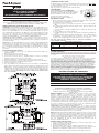
WIRING AND INSTALLATION DIAGRAMS BELOW
CAUTION: To be installed by a certified electrician or other qualified person. To
prevent severe shock or electrocution, always turn power OFF at the service
panel before installing this unit. Use only copper or copper clad wire with this
device. Use with paddle fans only. Use with incandescent lamps only. Do not
exceed the maximum wattage of the dimmer or the maximum amperage of the
fan control. To reduce the risk of overheating and possible damage to other
equipment, do not install to control a receptacle, a fluorescent lighting fixture,
a motor operated appliance, or a transformer supplied appliance.
GANGING MULTIPLE DIMMERS – This Control may be ganged together
without derating. Fan speeds vary by manufacturer. Some fans may turn too
slowly at the lowest setting. The light dimmer requires a minimum 25 watt load
for proper operation.
Attention: In most retrofit applications, it is necessary to add an additional wire
from the Control to the Fan. This is necessary to achieve independent control
and maximize the versatility of the Fan & Light. The additional wire should not
be confused with the Neutral wire, usually White, nor the Ground wire, normally
Bare or Green. Retrofit installations should be done only by a certified
electrician.
INSTALLATION INSTRUCTIONS:
1. Prior to installation, set the fan to its highest speed and the light to its
brightest setting.
2. Disconnect power to the circuit.
3. Strip installed wires per the chart below.
4. Connect the Control’s wires to installed wiring as shown in the Wiring
Diagram using the wire connectors provided.
5. Mount the Control to outlet box using mounting screws provided.
6. Attach the wall plate to Control using colored mounting screws provided.
7. Set the fan control to its OFF (lowest) position.
8. Restore power to the circuit.
9. Test the installation by operating the Control according to the Operating
Instructions below. Be sure the fan starts and does not stall in any of the
ON positions. The best operation may be obtained by starting the fan in the
highest setting and then moving the control to the desired speed. Do not
allow the fan to remain stalled. This may overheat the fan. DO NOT USE
THE PULL CHAIN TO CONTROL THE FAN SPEED AFTER INSTALLATION
OF THIS CONTROL.
OPERATING INSTRUCTIONS:
Toggle the light or fan switch provided to turn the respective unit ON or OFF.
To change lighting level or fan speed, slide the respective knob up or down
until desired level is reached.
Use only copper or copper clad wire with this device.
LIGHT MODULE:
(Sold separately, Catalog #TM8LMCC)
Transform in minutes a standard dimmer into an
illuminated dimmer (ON when light is OFF) –
allows the dimmer to be found in the dark.
Average 20-year life expectancy.
No wiring – quick snap-in installation.
IMPORTANT NOTES:
1. All Fan Speed Controls can be damaged by improper wiring. Check for
short circuits prior to installing the fan speed control.
Procedure for short circuit check:
a. Disconnect power to circuit by removing fuse or turn circuit breakers
OFF.
b. Install a switch instead of the fan speed control. Turn the switch to the
“ON” position.
c. If the fan fails to turn ON and OFF with the switch, the wiring may be
incorrect.
d. Correct wiring, if necessary and retest.
e. Install the fan speed control only after the fan operates properly with the
switch.
2. Protect from dirt and dust. The Fan Speed Control can be damaged from
contaminants encountered during the construction process. The control
should not be installed until the construction process is complete.
Any Fan Speed Control damage due to improper installation is not
covered under warranty.
LIFETIME WARRANTY
T
he device you have purchased is warranted under normal use against defects in workman-
ship and materials for as long as you own the device. If the device fails due to manufactur-
ing defect during normal use, return the device for replacement to the store where purchased
or send to:
Pass & Seymour Legrand Consumer Division
50 Boyd Avenue, Syracuse, NY 13209
A
ll requests for replacement must include a dated sales receipt (legible copies acceptable).
ALL OTHER WARRANTIES, INCLUDING BUT NOT LIMITED TO ANY WARRANTIES OF
MERCHANTABILITY OR FITNESS FOR A PARTICULAR PURPOSE, ARE LIMITED TO A
PERIOD OF TWO YEARS FROM THE DATE OF PURCHASE. YOUR SOLE AND EXCLU-
SIVE REMEDY AGAINST PASS & SEYMOUR LEGRAND UNDER ANY WARRANTY SHALL
BE THE EQUIVALENT REPLACEMENT OF THE DEVICE. IN NO EVENT SHALL ANY WAR-
RANTY APPLY TO ANY DEFECT ARISING OUT OF ANY ALTERATION OF THE DEVICE,
IMPROPER WIRING, IMPROPER INSTALLATION, MISUSE, ABNORMAL USE OR NEGLI-
GENCE. IN NO EVENT SHALL PASS & SEYMOUR LEGRAND BE LIABLE FOR LOST
PROFITS, INDIRECT, SPECIAL, EXEMPLARY, INCIDENTAL OR CONSEQUENTIAL DAM-
AGES. Some states do not allow limitations on how long implied warranties last and do not
allow exclusion or limitation of incidental or consequential damages. Some of the above
limitations or exclusions may not apply to every purchaser.
GRADATEUR ET CONTRÔLEUR DE VENTILATEUR
DE-HUMMER
®
Instructions d’installation pour les nouvelles constructions
Contrôleur de ventilateur De-Hummer
®
3 vitesses, unipolaire/3 voies :
1,6 A, 120 VCA, 60 Hz
Gradateur unipolaire/3 voies pour lampes incandescentes de 300 W :
120 VCA, 60 Hz
MISE EN GARDE : Doit être installé par un électricien certifié ou une autre
personne qualifiée. Pour éviter tout choc électrique ou une électrocution,
toujours couper l’électricité au niveau du panneau d’alimentation avant
d’installer ce dispositif. N’utiliser ce dispositif qu’avec des fils en cuivre ou
cuivrés. N’utiliser qu’avec des ventilateurs à pales. N’utiliser qu’avec des
lampes incandescentes. Ne pas dépasser la capacité maximale du gradateur
ou l’ampérage maximal du contrôleur. Pour éviter toute surchauffe et
endommagement éventuel des autres appareils, ne pas utiliser pour contrôler
une prise, une lampe ou un tube fluorescent, ou encore un appareil ménager
équipé d’un moteur ou alimenté par un transformateur.
GROUPEMENT DE PLUSIEURS GRADATEURS – Ce contrôleur peut être
combiné à d’autres dispositifs sans modifier sa puissance nominale. La vitesse
des ventilateurs varie selon le fabricant. Certains ventilateurs peuvent tourner
trop lentement dans la position la plus lente. Le gradateur doit avoir une charge
de 25 watts minimum pour fonctionner correctement.
Attention : Dans la plupart des applications de mise à niveau, il est nécessaire
d’ajouter un fil entre le contrôleur et le ventilateur. Ceci est nécessaire pour
assurer un contrôle indépendant et maximiser la souplesse d’utilisation de la
lampe et du ventilateur. Ce fil supplémentaire ne doit pas être confondu avec
le fil du neutre, habituellement blanc, ou le fil de terre, habituellement nu ou
vert. Les installations de mise à niveau doivent être effectuées par un
électricien certifié uniquement.
INSTRUCTIONS D’INSTALLATION
1. Avant l’installation, régler le ventilateur à sa vitesse la plus élevée et la
lumière à son intensité maximale.
2. Couper l’alimentation du circuit.
3. Dénuder les fils installés selon les indications du tableau ci-dessous.
4. Raccorder les fils du gradateur aux fils installés comme indiqué sur le
Diagramme de câblage en utilisant les connecteurs de fils fournis.
5. Fixer le contrôleur sur la boîte à l’aide des vis de fixation fournies.
INSTRUCTIONS D’INSTALLATION
CONTRÔLEUR DE VENTILATEUR ET GRADATEUR
POUR LAMPES INCANDESCENTES, À DEUX
CURSEURS AVEC PRÉRÉGLAGE
INSTRUCTIONS EN FRANÇAIS
L I R E E T C O N S E R V E R C E S I N S T R U C T I O N S
WIRE CONNECTOR USAGE CHART
CONNECTOR WIRE COMBINATIONS WIRE STRIP LENGTH
LARGE 1 #14 + 1 #18 7/16" (11mm) for Solid wire
1/2" (13mm) for Stranded wire
SMALL 1 #18 3/8" (9.5mm) for Solid wire
Strip wires per chart. Align ends. Push wires firmly into connector. Screw connector securely onto
wires. Note: The Control is supplied with #18 wire.
Fan
Speed
Control
Knob
Optional
Light
Module
Light Level
Control
Knob
Fan
Switch
Light
Switch

6. Fixer la plaque murale sur le contrôleur à l’aide des vis de fixation de
couleur fournies.
7. Régler le contrôleur du ventilateur sur sa position la plus basse
(OFF/ARRÊT).
8. Remettre le circuit sous tension
9. Tester l’installation en faisant fonctionner le contrôleur selon les Instructions
d’utilisation ci-dessous. S’assurer que le ventilateur démarre et ne s’arrête
dans aucune des positions ON (MARCHE). Pour assurer le meilleur
fonctionnement, il peut s’avérer utile de démarrer le ventilateur à sa position
la plus élevée, puis de réduire sa vitesse jusqu’à la valeur désirée. Ne pas
laisser le ventilateur en position « calée » . Ceci pourrait faire surchauffer le
ventilateur. NE PAS UTILISER LA CHAÎNE POUR CONTRÔLER LA VITESSE
DU VENTILATEUR APRÈS L’INSTALLATION DE CE CONTRÔLEUR.
INSTRUCTIONS D’UTILISATION
Basculer l’interrupteur de la lumière ou du ventilateur pour l’allumer
ou
l’éteindre.
Pour modifier l’intensité lumineuse ou la vitesse du ventilateur, faire glisser le
curseur correspondant jusqu’au niveau souhaité.
N’utiliser ce dispositif qu’avec des fils en cuivre ou cuivrés.
MODULE LUMINEUX : (vendu
séparément, n° de catalogue TM8LMCC)
Permet de transformer en quelques
minutes un gradateur standard en un
gradateur lumineux (ALLUMÉ lorsque la
lumière est ÉTEINTE) – Permet de trouver
le gradateur dans le noir.
Durée de vie moyenne : 20 ans
Pas de câblage – Installation rapide par enfichage
REMARQUES IMPORTANTES :
1. Tous les contrôleurs de vitesse de ventilateur peuvent être endommagés
par un câblage incorrect. Vérifier qu’il n’y a pas de court-circuit avant
d’installer le contrôleur.
Comment vérifier l’absence de court-circuit :
a. Couper l’alimentation du circuit en retirant le fusible ou en ouvrant les
disjoncteurs (ARRÊT / OFF).
b. Installer un interrupteur à la place du contrôleur. Mettre l’interrupteur en
position fermée (MARCHE / ON).
c. Si le ventilateur ne démarre ou ne s’arrête pas correctement, le câblage
peut être incorrect.
d. Rectifier le câblage si besoin est, et retester le circuit.
e. Installer le contrôleur uniquement si le ventilateur fonctionne correcte-
ment avec l’interrupteur.
2. Protéger le dispositif de la saleté et de la poussière. Le contrôleur de vitesse
peut être endommagé par des débris laissés au cours de la construction. Le
contrôleur ne doit pas être installé avant la fin de la construction.
Aucun contrôleur de vitesse de ventilateur endommagé par une
installation incorrecte n’est couvert par la garantie.
GARANTIE À VIE
L’appareil que vous venez d’acheter est garanti, sous condition d’utilisation normale,
contre tout défaut dans la fabrication et les matériaux tant qu’il est en votre possession. Si
cet appareil tombe en panne à cause de défauts de fabrication pendant son utilisation
normale, le rapporter pour qu’il soit remplacé, le cas échéant, là où vous l’avez acheté ou
l’envoyer à: Pass & Seymour Legrand, 50 Boyd Avenue, Syracuse, NY 13209
Toute demande de remplacement doit contenir un reçu de vente (photocopies lisibles
acceptées).
TOUTES AUTRES GARANTIES, Y COMPRIS MAIS NON LIMITEES A TOUTE GARANTIE
DE COMMERCIALISATION OU APTITUDE A SATISFAIRE UNE FONCTION PARTIC-
ULIERE, SONT LIMITEES A UNE PERIODE DE DEUX ANS A COMPTER DE LA DATE
D’ACHAT. VOTRE RECOURS UNIQUE ET EXCLUSIF CONTRE PASS & SEYMOUR
LEGRAND SOUS TOUTE GARANTIE EST LE REMPLACEMENT EQUIVALENT DE VOTRE
APPAREIL. EN AUCUN CAS LA GARANTIE NE S’APPLIQUE A DES DEFAUTS DE FONC-
TIONNEMENT DUS A DES MODIFICATIONS DE L’APPAREIL, UN CABLAGE INCORRECT,
UNE INSTALLATION INCORRECTE, UNE MAUVAISE UTILISATION, UNE UTILISATION
ANORMALE OU DE LA NEGLIGENCE. EN AUCUN CAS PASS & SEYMOUR LEGRAND
N’EST RESPONSABLE POUR UNE PERTE DE PROFIT, OU DES DEGATS INDIRECTS,
PARTICULIERS, EXEMPLAIRES, MINEURS OU CONSEQUENTS. Certains états n’autori-
sent pas de limite sur la durée des garanties implicites et ne permettent pas d’exclusion ou
de limite quant aux dégâts mineurs ou conséquents. Il se peut que certaines des limites ou
exclusions ci-dessus ne s’appliquent pas à tous les acheteurs.
DE-HUMMER
®
CONTROL DE VENTILADOR Y ATENUADOR
Instrucciones de instalación para construcciones nuevas
Control de ventilador De-Hummer
®
unipolar
3 vías, 3 velocidades: 1,6 A, 120 VCA, 60 Hz
Atenuador para bombillas incandescentes unipolar
3 vías de 300 W: 120 VCA, 60 Hz
PRECAUCIÓN: Para ser instalado por un electricista certificado y otra persona
calificada. Para evitar serios electrochoques o electrocución, siempre APAGUE
el suministro eléctrico en el panel de servicio antes de instalar esta unidad.
Sólo utilice alambre de cobre o cobrizado con este dispositivo. Utilice con
ventiladores de paletas únicamente. Utilice con focos incandescentes
únicamente. No exceda el vataje máximo del atenuador o el amperaje máximo
del control del ventilador. Para reducir el riesgo de recalentamiento y los
posibles daños a otro equipo, no lo instale para controlar un tomacorriente, un
artefacto de iluminación fluorescente, un electrodoméstico a motor o un
electrodoméstico equipado con transformador.
CONEXIÓN EN TÁNDEM DE ATENUADORES MÚLTIPLES – Este control puede
conectarse en tándem sin reducir la capacidad nominal. Las velocidades de los
ventiladores varían de acuerdo con el fabricante. Algunos ventiladores podrían
girar demasiado lento en la posición más baja. El atenuador de luz requiere una
carga mínima de 25 vatios para funcionar correctamente.
Atención: En la mayoría de las aplicaciones de reacondicionamiento, es
necesario agregar un alambre. adicional no debe confundirse con el alambre
neutro, habitualmente blanco, ni con el alambre de conexión a tierra,
normalmente desnudo o verde. Las instalaciones de reacondicionamiento sólo
deben ser realizadas por un electricista certificado.
INSTRUCCIONES DE INSTALACIÓN:
1. Antes de la instalación, ajuste el ventilador a su velocidad más alta y la luz
a su posición de mayor intensidad.
2. Desconecte la corriente al circuito.
3. Desforre los alambres instalados de acuerdo con la tabla presentada abajo.
4. Conecte los alambres del control al cableado instalado, tal como se
muestra en el Diagrama de cableado usando los conectores para alambre
suministrados.
5. Monte el control en la caja de salida con los tornillos de montaje
suministrados.
6. Conecte la placa de pared al control con los tornillos de montaje
suministrados.
7. Coloque el control de ventilador en su posición de APAGADO (más baja).
8. Restaure la corriente al circuito.
9. Pruebe la instalación operando el control de acuerdo con las instrucciones
de operación que se indican abajo. Asegúrese de que el ventilador
arranque y que no se bloquee en ninguna de las cuatro posiciones de
ENCENDIDO. El mejor funcionamiento puede obtenerse arracando
elventilador a la velocidad más alta y luego moviendo el control a la
velocidad deseada. No permita que el ventilador continúe bloqueado. Esto
podría causar recalentamiento. NO USE LA CADENA DE TIRO PARA
CONTROLAR LA VELOCIDAD DEL VENTILADOR DESPUÉS DE HABER
INSTALADO ESTE CONTROL.
INSTRUCCIONES DE OPERACIÓN:
Mueva la báscula del interruptor de luz o del ventilador suministrado para
ENCENDER
o APAGAR la unidad respectiva.
Para cambiar el nivel luminoso o la velocidad del ventilador, deslice la perilla
respectiva hacia arriba o hacia abajo hasta alcanzar el nivel deseado.
Use solamente alambre de cobre o recubierto de cobre con este aparato.
MÓDULO LUMINOSO: (vendido separado,
N° de catálogo TM8LMCC)
Transforme en minutos un control
estándar del ventilador en un control
iluminado (ENCENDIDO cuando la luz
está APAGADA) – permite encontrar el
control en la oscuridad.
20 años de expectativa de vida promedio.
Instalación con inserción rápida – no requiere cableado.
NOTAS IMPORTANTES:
1. Todos los controles de velocidad de ventilador pueden dañarse a causa de
un cableado incorrecto. Antes de instalar el control de velocidad de
ventilador, revise en busca de cortocircuitos.
Procedimiento de revisión para localizar cortocircuitos:
a. Desconecte el suministro eléctrico al circuito quitando el fusible o
apagando los cortacircuitos (OFF).
b. Instale un interruptor en lugar del control de velocidad de ventilador.
Coloque el interruptor en la posición encendido (ON).
c. Encienda el suministro eléctrico. Si el cortacircuitos se dispara, existe
un cortocircuito. Si el ventilador no se enciende y apaga con el
interruptor, el cableado podría estar incorrecto.
d. Si es necesario, corrija el cableado, y pruebe nuevamente.
e. Instale el control de velocidad de ventiladorúnicamente después de que
el ventilador funcione apropiadamente con el interruptor.
2. Proteja contra la suciedad y el polvo. El control de velocidad de ventilador
puede dañarse por contaminantes que se generan durante el proceso de
construcción. El control no debe instalarse antes de terminar la
construcción.
Cualquier daño del control de velocidad de ventilador causado por una
instalación incorrecta no está amparado por la garantía.
GARANTÍAS DE POR VIDA
El dispositivo que compró está garantizado bajo uso normal contra defectos de mano de obra
y de materiales mientras usted posea el dispositivo. Si el dispositivo falla debido a un defecto
de fabricación durante el uso normal, devuélvalo para su reemplazo a la tienda donde lo com-
pró o envíelo a: Pass & Seymour Legrand Consumer Division, 50 Boyd Avenue, Syracuse, NY
13209. Todas las solicitudes de reemplazo deben incluir un recibo de compra con fecha (se
aceptan copias legibles).
CUALQUIER OTRA GARANTÍA, INCLUYENDO PERO SIN LIMITARSE A CUALQUIER
GARANTÍA DE APTITUD E IDONEIDAD PARA UN FIN CONCRETO, ESTÁ LIMITADA A UN
PERÍODO DE DOS AÑOS A PARTIR DE LA FECHA DE COMPRA. SU RECURSO ÚNICO Y
EXCLUSIVO EN CONTRA DE PASS & SEYMOUR/LEGRAND BAJO CUALQUIER GARANTÍA
SERÁ EL REEMPLAZO DEL DISPOSITIVO POR UNO EQUIVALENTE. EN NINGÚN CASO
SE APLICARÁ GARANTÍA ALGUNA A UN DEFECTO DERIVADO DE UNA ALTERACIÓN
DEL DISPOSITIVO, CABLEADO INCORRECTO, INSTALACIÓN INCORRECTA, USO
INADECUADO, USO ANORMAL O NEGLIGENCIA. PASS & SEYMOUR/LEGRAND NO
SERÁ LEGALMENTE RESPONSABLE EN NINGÚN CASO POR LA PÉRDIDA DE INGRESOS,
DAÑOS Y PERJUICIOS INDIRECTOS, ESPECIALES, EJEMPLARES, INCIDENTALES O
CONSECUENTES. Algunos estados no permiten limitaciones en cuanto a la duración de las
garantías implícitas y no permiten la exclusión o limitación de los daños incidentales o cons
cuentes. Algunas de las limitaciones o exclusiones anteriores podrían no corresponder a
todos los compradores.
INSTRUCCIONES DE INSTALACIÓN
BARRA CORREDIZA DOBLE DE CONTROL
VARIABLE DE VENTILADOR Y ATENUADOR
DE LUZ INCANDESCENTE
INSTRUCCIONES EN ESPAÑOL
L E A Y R E T E N G A E S T A S I N S T R U C C I O N E S
Part No. 340889
©2009 Pass & Seymour/Legrand, 50 Boyd Avenue, Syracuse, NY 13209 (800) 223-4185
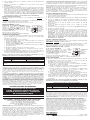
TABLA DE UTILIZACIÓN DE LOS CONECTORES DE ALAMBRE
CONECTOR COMBINACIONES DE ALAMBRES LONGITUD DE DESFORRADO DEL ALAMBRE
GRANDE 1 #14 + 1 #18 7/16 pulg. (11 mm) para alambre sólido
1/2 pulg. (13 mm) para alambre trenzado
PEQUEÑO 1 #18 3/8 pulg. (9.5 mm) para alambre sólido
Desforre los alambres de acuerdo con la tabla. Alinee los extremos. Empuje los alambres firmemente
en el conector. Atornille el conector en forma segura sobre los alambres. Nota: El control se
suministra con alambre #18.
Perilla de control
de velocidad del
ventilador
Módulo de
luz opcional
Interruptor del
ventilador
I
nterruptor
d
e luz
P
erilla
d
e control
d
e nivel
l
uminoso
TABLEAU D’UTILISATION DES CONNECTEURS DE FILS
CONNECTEUR COMBINAISONS DE FILS LONGUEUR DE DÉNUDAGE DES FILS
GROS 1 #14 + 1 #18 7/16 po (11 mm) pour fil massif
1/2 po (13 mm) pour fil torsadé
PETIT 1 #18 3/8 po (9,5 mm) pour fil massif
Dénuder les fils selon les indications du tableau. Aligner les extrémités. Enfoncer les fils fermement
dans le connecteur. Bien visser le connecteur sur les fils. Remarque : Le contrôleur est fourni avec
des fils #18.
B
outon du
c
ontrôleur
d
e vitesse
d
u ventilateur
Optionnel
module
lumineux
B
outon
d
u gradateur
d
’intensité
lumineuse
Interrupteur
du ventilateur
Interrupteur
de la
lumière
-
 1
1
-
 2
2


Legrand Dual Slide De-hummer Fan Control and Incandescent Light Dimmer Guía de instalación
- Tipo
- Guía de instalación
- Este manual también es adecuado para
en otros idiomas
Artículos relacionados
-
Legrand LSDD300W Guía de instalación
-
-
-
-
-
-
Legrand LSCL450W Guía de instalación
-
Legrand PS-Install-DRCL453P Guía de instalación
-
-
