John Deere Saw ET-3403-J Manual de usuario
- Categoría
- Sierras de inglete
- Tipo
- Manual de usuario
Este manual también es adecuado para

10-Inch Compound Miter Saw Operator's Manual 1
CAUTION
RISK OF INJURY!
READ MANUAL BEFORE OPERATING!
THIS MANUAL IS AN IMPORTANT PART OF THE MITER SAW
AND SHOULD REMAIN WITH THIS UNIT WHEN YOU SELL OR RENT IT.
ET-3403-J 10-INCH
COMPOUND MITER SAW

2 10-Inch Compound Miter Saw Operator's Manual
Congratulations on the purchase of your new Compound Miter Saw! You can be assured your compound miter saw
was constructed and designed with quality and performance in mind. Each component has been rigorously tested to
ensure the highest level of acceptance.
This operator's manual was compiled for your benefit. By reading and following the simple safety, installation, opera-
tion, maintenance and troubleshooting steps described in this manual, you will receive years of trouble-free operation
from your new heavy duty impact wrench. The contents of this manual are based on the latest product information
available at the time of publication. The manufacturer reserves the right to make changes in price, color, materials,
equipment, specifications or models at any time without notice.
Once the unit has been removed from the box, immediately write in the serial number of your unit in the space provided
below.
SERIAL NUMBER_________________________________
Inspect for signs of obvious or concealed freight damage. If damage does exist, file a claim with the transportation company
immediately. Be sure that all damaged parts are replaced and that the mechanical problems are corrected prior to operation
of the unit. If you require service, contact your Customer Service.
Mi-T-M
®
Corporation, 8650 Enterprise Drive, Peosta, IA 52068
1-877-JD-KLEEN / (1-877-535-5336) Fax 563-556-1235
Monday - Friday 8:00 a.m. - 5:00 p.m. CST
Please have the following information available for all service calls:
1. Model Number
2. Serial Number
3. Date and Place of Purchase
Introduction
WEAR RESPIRATORY PROTECTION
Some dust created by power sanding, sawing, grinding, drilling and other construction activities contain chemicals
known to the State of California to cause cancer, birth defects or other reproductive harm. Some examples of
these chemicals are:
• Lead from lead-base paints,
• Crystalline Silica from bricks, cement and other masonry products, and
• Arsenic and Chromium from chemically-treated lumber.
Your risk from these exposures varies, depending on how often you do this type of work. To reduce your exposure
to these chemicals, work in a well ventilated area and work with approved safety equipment, such as those dust
masks that are specially designed to filter out microscopic particles.
WARNING

10-Inch Compound Miter Saw Operator's Manual 3
Table of Content
SAFETY ....................................................................................................................................................... 4-9
GENERAL SAFETY RULES............................................................................................................ 4-9
FUNCTIONAL DESCRIPTION..................................................................................................................... 10-11
MODEL............................................................................................................................................ 10
NAME OF PARTS ........................................................................................................................... 10
SPECIFICATIONS........................................................................................................................... 11
PREPARATION ........................................................................................................................................... 12
OPERATION ................................................................................................................................................ 13-21
APPLICATIONS .............................................................................................................................. 13
PRE-OPERATION........................................................................................................................... 13-15
OPERATION ................................................................................................................................... 16-20
SAW BLADE MOUNTING AND DISMOUNTING ............................................................................ 21
MAINTENANCE AND INSPECTION............................................................................................................ 22-23
MAINTENANCE AND INSPECTION ............................................................................................... 22
STORAGE....................................................................................................................................... 23
LUBRICATION ................................................................................................................................ 23
CLEANING ...................................................................................................................................... 23
SERVICE AND REPAIRS................................................................................................................ 23
STANDARD ACCESSORIES .......................................................................................................... 23
FRENCH ...................................................................................................................................................... 24-45
SPANISH ..................................................................................................................................................... 46-67

4 10-Inch Compound Miter Saw Operator's Manual
RECOGNIZE SAFETY INFORMATION
This is the safety alert symbol. When you see this symbol on your tool or in
this manual, be alert to the potential for personal injury.
Follow recommended precautions and safe operating practices.
UNDERSTAND SIGNAL WORDS
A "DANGER, WARNING or CAUTION" safety warning will be surrounded by a
"SAFETY ALERT BOX." This box is used to designate and emphasize Safety
Warnings that must be followed when operating this tool.
Accompanying the Safety Warnings are "signal words" which designate the degree
or level of hazard seriousness. The "signal words" used in this manual are as
follows:
DANGER: Indicates an imminently hazardous situation
which, if not avoided, WILL result in death or serious injury.
WARNING:Indicates a potentially hazardous situation
which, if not avoided, COULD result in death or serious injury.
CAUTION: Indicates a potentially hazardous situation
which, if not avoided MAY result in minor or moderate injury.
Safety
GENERAL SAFETY RULES
WARNING: Read and understand all instructions.
Failure to follow all instructions listed below, may
result in electric shock, fire and/or serious personal injury.
SAVE THESE INSTRUCTIONS

10-Inch Compound Miter Saw Operator's Manual 5
ALWAYS KEEP GUARDS IN PLACE and in working order.
ALWAYS KEEP WORK AREA CLEAN
Avoid injuries by not cluttering the work areas and work benches.
NEVER USE TOOL IN HAZARDOUS
ENVIRONMENTS
Never use the power tool in damp or wet places and never expose it to rain.
Always keep the work area well lighted.
NEVER PERMIT CHILDREN OR OTHERS TO LOITER NEAR THE WORK
AREA
Keep all people (especially children) away from the work area. Always unplug
unattended tools and keep the work place tamper-proof by installing locks on the
doors and on the master switches.
ALWAYS WEAR PROPER APPAREL WHEN WORKING WITH THE TOOL
Never wear loose clothing, gloves, neckties, rings, bracelets or other jewelry
which may get caught in the moving parts. Always wear nonslip footwear,
preferably with steel toes. Wear protective hair covering to contain long hair.
ALWAYS USE EYE PROTECTION WHEN WORKING WITH THE TOOL TO
PREVENT EYE INJURY
Ordinary eyeglasses do not provide adequate protection because they have only
impact resistant lenses, they are NOT safety glasses. Also, use a face mask for
additional safety and wear a dust mask if the cutting operation produces dust.
ALWAYS SECURE THE WORKPIECE TO THE FENCE OR THE TABLE
Use clamps or a vise to hold the workpiece in place. It is safer than using your
hand and it frees both hands to operate the tool.
NEVER OVERREACH
Always keep proper footing and balance when working with the tool.
ALWAYS DISCONNECT THE TOOL
before servicing and before changing blades or other accessories.
NEVER RISK UNINTENTIONAL STARTING WHEN PLUGGING IN THE TOOL
Always confirm that the switch is in the OFF position before inserting the power
plug into the receptacle.
NEVER STAND ON THE TOOL
Serious injury could occur if the tool is tipped or if unintentional contact with the
saw blade is made.
NEVER LEAVE THE TOOL RUNNING WHILE UNATTENDED. TURN POWER
OFF
Do not leave tool until it comes to a complete stop. Always turn the power off
when the tool is not in use. Always unplug the power cord when the tool is not in
use.
WARNING

6 10-Inch Compound Miter Saw Operator's Manual
WARNING
CAUTION
FOR YOUR OWN SAFETY READ THIS INSTRUCTION MANUAL BEFORE OPERATING THE COMPOUND
MITER SAW
1. Always wear eye protection when using the compound miter saw.
2. Always keep hands out of the path of the saw blade.
3. Never operate the saw without the guards in place.
4. Never perform any freehand operation with the compound miter saw.
5. Never reach around the saw blade.
6. Always turn off tool and wait for saw blade to stop before moving workpiece or changing settings.
7. Always disconnect power before changing blade or servicing.
8. Saw blade diameter is 10" (255mm).
9. No load speed is 4900 min
-1
.
ALWAYS REMOVE ADJUSTING KEYS AND WRENCHES BEFORE STARTING TOOL
Always confirm that all keys and adjusting wrenches have been removed from the tool before it is turned on.
NEVER FORCE THE TOOL
It will do the job better and more safely if it is operated at the rate for which it was designed.
ALWAYS USE THE RIGHT TOOLS
Never force a tool or an attachment to do a job for which it was not designed.
ALWAYS MAINTAIN TOOLS WITH CARE
Always keep tools sharp and clean for the best and safest performance. Always follow instructions for lubricating
the tool and for changing accessories.
ALWAYS USE RECOMMENDED ACCESSORIES ONLY WHEN OPERATING THIS TOOL
Consult this instruction manual for descriptions of recommended accessories. To avoid personal injuries, use only
recommended accessories in conjunction with this tool.
ALWAYS CHECK FOR DAMAGED PARTS BEFORE USING THE TOOL
Always check the guard and all other components for damage before using the tool to assure that they will function
properly. Check all moving parts for proper alignment, free from binding and other conditions that might affect
proper operation. Always repair or replace any damaged guards or other damaged components before using the
tool.
ALWAYS CONFIRM THE ROTATION DIRECTION OF THE BLADE BEFORE USING THE TOOL
Always feed work into the tool against the rotation direction of the blade in order to prevent possible injury.
This tool was not designed to be used for mass-production applications and should not be used in mass-produc-
tion environments.
When servicing this tool, use only authorized replacement parts.
Apply 115 volts AC only to this tool. Applying the wrong voltage or applying DC power can cause the POWER
TOOL to operate improperly and cause serious personal injury or damage the tool.
Never raise the saw blade from the workpiece until it has first come to a complete stop.
Always use outboard stands to provide support for long workpieces that overhang the table of the compound saw.

10-Inch Compound Miter Saw Operator's Manual 7
POLARIZED PLUGS
To reduce the risk of electric shock, this equipment has a polarized plug (one blade is wider than the other). This
plug will fit in a polarized outlet only one way. If the plug does not fit fully in the outlet, reverse the plug. If it still does
not fit, contact a qualified electrician to install the proper outlet. Do not change the plug in any way.
EXTENSION CORD
Make sure your extension cord is in good condition. When using an extension cord, be sure to use one heavy
enough to carry the current your product will draw. An undersized cord will cause a drop in line voltage resulting in
loss of power and overheating. Table shows the correct size to use depending on cord length and nameplate
ampere rating. If in doubt, use the next heavier gage. The smaller the gage number, the heavier the cord.
DOUBLE INSULATION SYSTEM ENHANCES SAFE OPERATION
To enhance safe operation of this electric power tool, JOHN DEERE has adopted a double insulation system. The
term "double insulation" used here denotes an insulation systems with two insulations physically separated and
arranged between the electrically conductive material connected to the power supply and outer frame subject to
contact by the operator.
Thus, the power tool is termed double insulated and both the mark and " " double insulation", or either one is
indicated on the name plate.
While no external grounding is required with this system, normal safety precautions as outlined in this manual must
still be followed.
To maintain the effectiveness of the double insulation system, follow the precautions described below:
1. Always contact your John Deere Dealer when assembling, disassembling or replacing parts other than
accessories or carbon brushes. Improper assembly and/or replacement with wrong parts may result in
eliminating the double insulation-feature.
2. Clean the exterior of the tool with a soft cloth moistened with soapy water, and dry thoroughly. Choleric
solvent, gasoline, and thinner will cause plastic components to dissolve.
WARNING: AVOID ELECTRICAL SHOCK HAZARD. NEVER USE THIS TOOL
WITH A DAMAGED OR FRAYED ELECTRICAL CORD OR
EXTENSION CORD. INSPECT ALL ELECTRICAL CORDS
REGULARLY. NEVER USE IN OR NEAR WATER OR IN ANY
ENVIRONMENT WHERE ELECTRIC SHOCK IS POSSIBLE.
CAUTION
Table 1
MINIMUM GAGE FOR CORD SETS
Total Length of Code in Feet (Meter)
0-25 26-50 51-100 101-150
(0-7.6) (7.9-15.2) (15.5-30.5) (30.8-45.7)
Ampere Rating AWG Size of Cord
More Not More
Than Than
0 6 18 16 16 14
6 10 18 16 14 12
10 12 16 16 14 12
12 16 14 12 Not recommended
DOUBLE INSULATION

8 10-Inch Compound Miter Saw Operator's Manual
IMPORTANT
SPECIFIC SAFETY RULES FOR USE OF THIS POWER TOOL
WARNING: THE FOLLOWING SPECIFIC OPERATING INSTRUCTIONS MUST BE OBSERVED WHEN
USING THIS POWER TOOL IN ORDER TO AVOID INJURY.
DO's:
ALWAYS OBSERVE THE FOLLOWING RULES TO ASSURE SAFE USE OF THIS TOOL:
1. Review the Manual and familiarize yourself with the safety rules and operatinginstructions for this POWER
TOOL before attempting to use it.
2. Always confirm that the POWER TOOL is clean before using it.
3. Always wear snug-fitting clothing, nonskid footwear (preferably with steel toes) and eye protection when
operating the POWER TOOL.
4. Always handle the POWER TOOL carefully. If the POWER TOOL falls or strikes against a hard object, it might
become deformed or cracked or sustain other damage.
5. Always cease operating the saw at once, if you notice any abnormality what so ever.
6. Always confirm that all components are mounted properly and securely before using the tool.
7. When replacing the saw blade, always confirm that the rating of the new blade is correct for use on this tool.
8. Always shut off the power and wait for the saw blade to completely stop rotating before doing any maintenance
or adjustments.
9. Always clamp or otherwise secure the workpiece to the fence; otherwise the workpiece might be thrust from the
table and cause bodily harm.
10. During miter or bevel cutting, always wait for the rotation of the blade to stop completely before lifting the saw
blade.
11. Always make a trial run first before attempting any new use of the saw.
12. Always handle the saw blade with care when dismounting and mounting it.
13. Always confirm that the workpiece is free of nails or other foreign objects before beginning a cut.
14. Always keep your hands out of the path of the saw blade.
15. Always confirm that the safety cover is in the proper place before using the saw.
16. Inspect the tool's power cord periodically.
17. Always confirm that the proper lengths and types of extension cords are being utilized, if necessary, before
starting the tool.
18. Always confirm that the motor air vents are fully open before using the tool.
19. Always wait until the motor has reached full speed before starting a cut.
20. Always keep the handles dry, clean and free of oil and grease. Hold the tool firmly when in use.
21. Always use outboard stands to provide support for long workpieces that overhang the table of the compound
miter saw.
22. Always operate the tool after ensuring the workpiece is fixed properly with a vise assembly.
23. The operating instructions provided with the tool shall direct the user to secure the tool to supporting structure if,
during normal operation, there is a tendency for the tool to tip over, slide, or walk on the supporting surface.

10-Inch Compound Miter Saw Operator's Manual 9
REPLACEMENT PARTS
When servicing use only identical replacement parts.
Repairs should be conducted only by a JOHN DEERE authorized dealer.
SAVE THESE INSTRUCTIONS
AND MAKE THEM AVAILABLE TO OTHER USERS OF THIS TOOL!!
SPECIFIC SAFETY RULES FOR USE OF THIS POWER TOOL
WARNING: THE FOLLOWING SPECIFIC OPERATING INSTRUCTIONS MUST BE OBSERVED WHEN
USING THIS POWER TOOL IN ORDER TO AVOID INJURY.
DON'Ts:
NEVER VIOLATE THE FOLLOWING RULES TO ASSURE SAFE USE OF THIS TOOL:
1. Never operate the POWER TOOL unless you fully understand the operating instructions contained in this
Manual.
2. Never leave the POWER TOOL unattended without first unplugging the power cord.
3. Never operate the POWER TOOL when you are tired, after you have taken any medications, or have
consumed any alcoholic beverages.
4. Never use the POWER TOOL for applications not specified in the instruction manual.
5. Never operate the tool while wearing loose clothing, a necktie or jewelry, or while your hair is uncovered, to
protect against getting caught in the moving machinery.
6. Never reach around the saw blade.
7. Never touch any moving parts, including the blade, while the saw is in use.
8. Never remove any safety devices or blade guards; use of the tool without them would be hazardous.
9. Never lock the safety cover; always confirm that it slides smoothly before using the tool.
10. Never damage the power cord of the tool.
11. Never attempt to move a plugged-in POWER TOOL while your finger is on the starting switch.
12. Never use the POWER TOOL if the starting switch does not turn on and off properly.
13. Never use the POWER TOOL if the plastic housing or the handle is cracked or deformed.
14. Never use the POWER TOOL near flammable liquids or gases because sparking can cause an explosion.
15. Never clean plastic components with solvents because the plastic may dissolve.
16. Never operate the saw unless all the blade guards are in place.
17. Never raise the saw blade from the workpiece until it has first come to a complete stop.
18. Never cut ferrous metals or masonry.
19. Never place your limbs inside of the line next to warning sign " " while the tool is being operated. This may
cause hazardous conditions.
20. Never use abrasive type blades on this saw.
21. Never expose to rain or use in damp locations.
22. When you cut the workpiece, avoid any cut off thinner than the clearance between the cutting edge and the saw
blade. Otherwise, the cut off material can enter the clearance between the cutting edge and the saw blade and
scatter around you, resulting in injury.
IMPORTANT

10 10-Inch Compound Miter Saw Operator's Manual
Functional Description
MODEL:
ET-3403-J 10-INCH COMPOUND MITER SAW
NOTE: The information contained in this Instruction Manual is designed to assist you in the safe operation and
maintenance of the power tool.
NEVER operate, or attempt any maintenance on the tool unless you have first read and understood all safety
instructions contained in this manual.
Some illustrations in this Instruction Manual may show details or attachments that differ from those on your own
power tool.
NAME OF PARTS:
(Fig. 1)
(Fig. 2)

10-Inch Compound Miter Saw Operator's Manual 11
SPECIFICATIONS:
COMPOUND MITER SAW ET-3403-J:
Motor Series Commutator Motor
Power Source Single-Phase AC 60Hz
Voltage (Volts) 115
Full-load Current (Amp) 15
Applicable saw blade Outside Dia. 10" (255 mm)
Hole Dia. 5/8" (15.9 mm)
No load speed 4900 min
-1
Max. sawing deminsions:
Bevel 0°:
Miter 0° Max. Height 2-1/4" (59 mm) (Max. Height 3-1/2" (89 mm)
Max. Width 5-5/8" (144 mm) (Max. Width 3-7/8" (101 mm)
Miter 45° Max. Height 2-1/4" (59 mm) (Max. Height 3-1/2" (89 mm)
Max. Width 4" (102 mm) (Max. Width 2-3/4" (70 mm)
Miter 60° Max. Height 2-1/4" (59 mm) (Max. Height 3-1/2" (89 mm)
Max. Width 2-3/4" (72 mm) (Max. Width 2" (55 mm)
Bevel 45°
Miter 0° Max. Height 1-5/8" (41 mm)
Max. Width 5-5/8" (144 mm)
Miter 45° Max. Height 1-5/8" (41 mm) (Max. Height 1-3/4" (44 mm)
Max. Width 4" (102 mm) (Max. Width 3-1/2" (89 mm)
Miter sawing range Left 0° - 45°, Right 0° - 60°
Bevel sewing range Left 0° - 45°
Net Weight 31 lbs (14 kg)
Cord 2 Conductor type cabtire cable 7.2 ft (2.2 m)
Functional Description

12 10-Inch Compound Miter Saw Operator's Manual
Preparation
PREPARATION:
Make the following preparations before operating the power tool:
1. Installation:
Attach the power tool to a level, horizontal work bench in
accordance with Fig. 3. Select 5/16" (8 mm) diameter
bolts suitable in length for the thickness of the work bench.
For example, use 2" (50 mm) or larger bolts for 1"
(25 mm) thick work bench. The holder attached to the rear of
the base helps stabilize the power tool.
2. Releasing the locking pin:
When the power tool is prepared for shipping, its main parts
are secured by a locking pin. Move the handle
(see Fig. 4) slightly so that the locking pin can be disengaged.
During transport, lock the locking pin into the gear case.
NOTE: Lowering the handle (See Fig. 1) slightly will enable you to
disengage the locking pin easily and safely. The lock
position of the locking pin is for carrying and storage only.
3. Installing the dust bag, holder and vises:
Attach the dust bag, holder, and vises as indicated in Fig. 1.
(Fig. 3)
(Fig. 4)

10-Inch Compound Miter Saw Operator's Manual 13
Operation
APPLICATIONS:
Wood, plywood, color board, soft fabric board, hard board similar materials and aluminum sash.
PRE-OPERATION:
1. Make sure that the power source is appropriate for the tool.
WARNING: NEVER CONNECT THE POWER TOOL UNLESS THE AVAILABLE AC POWER
SOURCE IS OF THE SAME VOLTAGE IS THAT SPECIFIED ON THE NAMEPLATE OF
THE TOOL. NEVER CONNECT THIS POWER TOOL TO A DC POWER SOURCE.
2. Make sure the trigger switch is turned OFF.
WARNING: IF THE POWER CORD IS CONNECTED TO THE POWER SOURCE WITH THE
TRIGGER SWITCH TURNED ON THE POWER TOOL WILL START SUDDENLY AND
CAN CAUSE A SERIOUS ACCIDENT.
3. Check the saw blade for visible defects:
Confirm that the saw blade is free of cracks or other visible damage.
4. Confirm that the saw blade is attached securely to the power tool:
Using the supplied wrench, tighten the bolt on the arbor shaft to secure the
saw blade. For details, see Fig. 25-a and Fig. 25-b in the section on
"SAW BLADE MOUNTING AND DISMOUNTING."
5. Check the safety cover for proper operation:
Safety cover is designed to protect the operator from coming into
contact with the saw blade during operation of the tool. Always
check that the safety cover moves smoothly and covers the saw
blade properly.
WARNING: NEVER OPERATE THE POWER TOOL IS THE
SAFETY COVER DOES NOT FUNCTION SMOOTHLY.
6. Confirm the position of the spindle lock before using the tool:
After installing the saw blade, confirm that the spindle lock has been returned to the retract position before
using the power tool (see Fig. 25-a).
7. Check the lower limit position of the Saw Blade:
Although it was adjusted before shipment, carefully check the height of the saw blade. Confirm that the saw
blade can be lowered 1-5/8" tp 1-21/32" (41 mm or 42 mm) below the table insert. For details, see the section
on "Checking the saw blade lower limit position".
8. Check the Power Receptacle:
To prevent overheating, accidental stopping or intermittent operation, confirm that the power cord plug fits
properly in the electrical receptacle and does not fall out after it is inserted. Repair and replace the receptacle if
it is faulty.
9. Confirm the tool's power cord is not damaged:
Repair or replace the power cord if an inspection indicates that it is damaged.
AFTER CONNECTING THE POWER PLUG TO AN APPROPRIATE AC POWER SOURCE, CHECK THE
OPERATION OF THE TOOL AS FOLLOWS:
10. Trial Run:
After confirming that no one is standing behind the power tool, start and confirm that no operating abnormalities
exist before attempting a cutting operation.
11. Inspect the rotating stability of the saw blade:
For precise cutting, rotate the saw blade and check for deflection to confirm that the blade is not noticeably
unstable; otherwise, vibrations might occur and cause an accident.
(Fig. 5)

14 10-Inch Compound Miter Saw Operator's Manual
Operation
PRE-OPERATION (CONTINUED):
BEFORE CUTTING:
1. Cutting groove on the table insert:
A groove has to be cut in the table insert, before starting operation.
Secure a piece of wood about 5-1/2" (140 mm) wide to the table with the
vise assembly, to prevent the breakage of the table insert. After the switch
hasbeen turned on and the saw blade has reached maximum speed,
slowly lower the handle to cut a groove on the table insert.
CAUTION: DO NOT CUT THE GROOVE TOO QUICKLY,
OTHERWISE THE TABLE INSERT MIGHT BECOME
DAMAGED.
2. Checking the saw blade lower limit position:
WARNING: TO PREVENT AN ACCIDENT OR PERSONAL
INJURY, ALWAYS TURN OFF THE TRIGGER SWITCH
AND DISCONNECT THE POWER PLUG FROM THE
RECEPTACLE BEFORE ADJUSTMENT.
Check that the saw blade can be lowered 1-5/8" to 1-21/32"
(41 mm to 42 mm) below the table insert. If necessary, adjust as follows:
a. Loosen the 8 mm lock nut on the 8 mm depth
adjustment screw.
b. Turn the 8 mm depth adjustment screw as necessary to set the lower
limit position. The saw blade goes up when the 8 mm depth
adjustment screw is turned counterclockwise and down when it is
turned clockwise.
c. Once the adjustment is complete, fully tighten the 8 mm lock nut.
NOTE: Before tightening the 8 mm lock nut, confirm that the saw blade is
adjusted so that it will not cut into the table.
3. Confirmation for use of sub fence:
WARNING: IN THE CASE OF LEFT BEVEL CUTTING, TURN THE SUB
FENCE COUNTERCLOCKWISE. UNLESS IT IS TURNED
COUNTERCLOCKWISE, THE MAIN BODY OR SAW
BLADE MAY CONTACT THE SUB FENCE, RESULTING IN
AN INJURY.
This power tool is equipped with a sub fence. (See Fig. 1) In the case of
direct angel cutting and angle cutting, use the sub fence.
In the case of left bevel cutting, raise the sub fence up as illustrated in
Fig. 8 and then turn it counterclockwise.
(Fig. 6)
(Fig. 7)
(Fig. 8)

10-Inch Compound Miter Saw Operator's Manual 15
Operation
PRE-OPERATION (CONTINUED):
4. Oblique angle:
Before the power tool is shipped from the factory, it is adjusted for 0° and left 45° bevel cutting angles. The
positioning and bevel cutting angle can be adjusted by changing the height of the 8 mm bolt. (Maximum bevel
cutting angle is 45°).
5. Securing the workpiece:
WARNING: ALWAYS CLAMP OR VISE, TO SECURE THE WORKPIECE TO THE FENCE;
OTHERWISE THE WORKPIECE MIGHT BE THRUST FROM THE TABLE
AND CAUSE BODILY HARM.
6. Installing the holders:
The holders help keep longer workpieces stable and in place during the cutting operation.
a. As indicated in Fig.11, use a steel square for aligning the upper edge of the holders with the base surface.
b. After aligning, secure the holders with the 6mm wing bolts.
7. Stopper for precision cutting:
The stopper facilitates continuous precision cutting in lengths of 10" to 16-1/2" (255mm to 420mm). To install
the stopper, attach it to the holder with the 6mm wing bolt as shown in Fig. 12.
(Fig. 9)
(Fig. 10)
(Fig. 11)
(Fig. 12)

16 10-Inch Compound Miter Saw Operator's Manual
OPERATION:
WARNING: TO AVOID PERSONAL INJURY, NEVER REMOVE OR PLACE A WORKPIECE ON
THE TABLE WHILE THE TOOL IS BEING OPERATED. NEVER PLACE YOUR
LIMBS INSIDE OF THE LINE NEXT TO WARNING SIGN WHILE THE TOOL IS BEING
OPERATED. THIS MAY CAUSE HAZARDOUS CONDITIONS (SEE FIG. 13).
1. Switch operation:
The trigger switch lock-off button is designed to prevent inadvertent operation of the power tool. To operate
the power tool, it is necessary to first fully insert the lock-off button into the hole on the handle as shown in
Fig. 14.
The trigger switch will not operate unless the lock-off button has beenpushed in. When the trigger switch is
released, the power goes off and the lock-off button automatically returns to its initial position, locking the
trigger switch.
WARNING: ALWAYS REMOVE THE LOCK-OFF BUTTON FROM THE HANDLE WHEN THE
POWER TOOL IS NOT IN USE. THIS WILL ENSURE THAT THE POWER TOOL
CANNOT BE TURNED ON ACCIDENTALLY OR BY SOMEONE (ESPECIALLY A
CHILD) WHO IS NOT QUALIFIED TO USE THE POWER TOOL. IF THE LOCK-OFF
BUTTON IS LEFT IN THE HANDLE, SERIOUS PERSONAL INJURY CAN RESULT.
SINCE THE LOCK-OFF BUTTON FITS RATHER TIGHTLY, IT MAY BE NECESSARY `
TO TURN IT TO THE LEFT AND RIGHT DURING MOUNTING AND REMOVING.
(Fig. 14)
(Fig. 13)
Operation

10-Inch Compound Miter Saw Operator's Manual 17
Operation
OPERATION (CONTINUED):
2. Using the vise assembly (Standard accessory):
a. The vise assembly can be mounted on either the left fence {Fence
(B)} or the right fence {Fence (A)} by loosening the 6 mm wing
bolt (A).
b. The screw holder can be raised or lowered according to the height of
the workpiece by loosening the 6 mm wing bolt (B). After the
adjustment, firmly tighten the 6 mm wing bolt (B) and fix the screw
holder.
c. Turn the upper knob and securely fix the workpiece in position
(Fig. 15).
WARNING: ALWAYS FIRMLY CLAMP OR VISE, TO SECURE THE
WORKPIECE TO THE FENCE; OTHERWISE THE
WORKPIECE MIGHT BE THRUST FROM THE TABLE AND
CAUSE BODILY HARM.
CAUTION: ALWAYS CONFIRM THAT THE MOTOR HEAD
(SEE FIG. 1) DOES NOT CONTACT THE VISE ASSEMBLY
WHEN IT IS LOWERED FOR CUTTING. IF THERE IS ANY
DANGER THAT IT MAY DO SO, LOOSEN THE 6 MM WING
BOLT (B) AND MOVE THE VISE ASSEMBLY TO A
POSITION WHERE IT WILL NOT CONTACT THE SAW
BLADE.
3. Cutting Operation:
a. As shown in Fig. 16 the width of the saw blade is the width of the cut.
Therefore, slide the workpiece to the right (viewed from the
operator's position) when length (b) is desired, or to the left when
length (a) is desired.
b. Once the saw blade reaches maximum speed, push the handle down
carefully until the saw blade approaches the workpiece.
c. Once the saw blade contacts the workpiece, push the handle down
gradually to cut into the workpiece.
d. After cutting the workpiece to the desired depth, turn the power tool
OFF and let the saw blade stop completely before raising the handle
from the workpiece to return it to the full retract position.
WARNING: CONFIRM THAT THE TRIGGER SWITCH IS TURNED OFF
AND THE POWER PLUG HAS BEEN REMOVED FROM
THE RECEPTACLE WHENEVER THE TOOL IS NOT IN
USE. WHEN YOU CUT THE WORKPIECE, AVOID ANY
CUTOFF THINNER THAN THE CLEARANCE BETWEEN
THE CUTTING EDGE AND THE SAW BLADE.
OTHERWISE, THE CUTOFF MATERIAL CAN ENTER THE
CLEARANCE BETWEEN THE CUTTING EDGE AND THE
SAW BLADE AND SCATTER AROUND YOU, RESULTING
IN AN INJURY.
CAUTION: INCREASED PRESSURE ON THE HANDLE WILL NOT
INCREASE THE CUTTING SPEED. ON THE CONTRARY,
TOO MUCH PRESSURE MAY RESULT IN OVERLOAD OF
THE MOTOR AND/OR DECREASED CUTTING
EFFICIENCY. IF THE HANDLE IS PRESSED DOWN WITH
EXCESSIVE OR LATERAL FORCE, THE SAW BLADE
MAY VIBRATE DURING THE CUTTING OPERATION AND
CAUSEUNWANTED CUTTING MARKS ON THE
WORKPIECE, THUS REDUCING THE QUALITY OF THE
CUT. ACCORDINGLY, PRESS THE HANDLE DOWN
GENTLY AND CAREFULLY.
(Fig. 15)
(Fig. 16)

18 10-Inch Compound Miter Saw Operator's Manual
Operation
OPERATION (CONTINUED):
4. Miter cutting procedures:
a. Loosen the side handle.
b. Adjust the table until the indicator aligns with the desired setting on the
miter angle scale as shown in Fig. 17.
c. Retighten the side handle to secure the table in the desired position.
CAUTION: NEVER REMOVE THE SIDE HANDLE; USE OF THE TOOL
WITHOUT IT WOULD BE HAZARDOUS. TO PREVENT AN
ACCIDENT OR PERSONAL INJURY ALWAYS FIRMLY
TIGHTEN THE MITER HANDLE.
NOTE: Positive stops are provided at the right and left of the 0° center
setting, at 15°, 22.5°, 31.6°, 35.3°, 45° and 60° right and 15°,
22.5°, 31.6°, 35.3°, and 45° left settings. Check that the miter
angle scale and the tip of the indicator are properly aligned.
*Operation of the power tool with the miter angle scale and
indicator out of alignment, or with the miter handle not
properly tightened, will result in poor cutting precision.
5. Bevel cutting procedures:
a. Loosen the clamp lever and bevel the saw blade to the left.
b. Adjust the bevel angle to the desired setting while watching the bevel
angle scale and indicator, then secure the clamp lever (Fig. 18).
WARNING: WHEN THE WORKPIECE IS SECURED ON THE LEFT SIDE
OF THE BLADE, THE SHORT CUTOFF PORTION WILL
COME TO REST ON THE RIGHT SIDE OF THE SAW
BLADE. ALWAYS TURN THE POWER OFF AND LET THE
SAW BLADE STOP COMPLETELY BEFORE RAISING THE
HANDLE FROM THE WORKPIECE. IF THE HANDLE IS
RAISED WHILE THE SAW BLADE IS STILL ROTATING, THE
CUTOFF PIECE MAY BECOME JAMMED AGAINST THE
SAW BLADE CAUSING FRAGMENTS TO SCATTER ABOUT
DANGEROUSLY.
6. Compound cutting procedures:
For compound cutting, follow the instructions in paragraphs 4 and 5 above.
At a bevel angle of 45° and a miter angle of 45°, a workpiece of 1-5/8"
(41 mm) in height and up to 4" (102 mm) in width can be cut.
CAUTION: ALWAYS SECURE THE WORKPIECE WITH THE RIGHT
HAND SIDE FOR COMPOUND CUTTING. NEVER ROTATE
THE TABLE TO THE RIGHT FOR COMPOUND CUTTING,
BECAUSE THE SAW BLADE MIGHT THEN CONTACT
THE CLAMP OR VISE THAT SECURES THE WORKPIECE,
AND CAUSE PERSONAL INJURY OR DAMAGE.
(Fig. 17)
(Fig. 18)

10-Inch Compound Miter Saw Operator's Manual 19
Operation
OPERATION (CONTINUED):
7. Crown molding cutting procedures:
Fig. 20 shows two common crown molding types having angles of (0) 38° and45°. For the typical crown molding
fittings, see Fig. 20.
(Fig. 19) (Fig. 20)
The table below shows the miter angle and the bevel angle settings that are ideal for the two crown molding
types.
NOTE: For convenience, positive stops are provided for the miter setting (left and right 31.6°, 35.3°)
positions.
For miter cut setting
If the table has been set to either of the angles described, move the table adjusting miter handle a little to the
right and left to stabilize the position and to properly align the miter angle scale and the tip of the indicator before
the operation starts.
For bevel cutting setting
Move handle on bevel section to the right and left and check that the position is stable and that the bevel angle
scale and the tip of the indicator are properly aligned. Then tighten the clamp lever.
Type of To process crown molding at To process crown molding at
Crown Molding positions (1) and (4) in Fig. 20 positions (2) and (3) in Fig. 20
Miter angle Bevel angle Miter angle Bevel angle
Setting Setting Setting Setting
45° Type right 35.3° 30° left 35.3° 30°
( mark) ( mark)
38° Type right 31.6° 33.9° left 31.6° 33.9°
( mark) ( mark) ( mark) ( mark)

20 10-Inch Compound Miter Saw Operator's Manual
Operation
OPERATION (CONTINUED):
Setting to cut crown moldings at positions (1) and (4) in Fig. 20 (see Fig. 21):
1. Turn the table to the right and set the Miter Angle as follows:
*For 45° type crown moldings: 35.3° ( mark)
*For 38° type crown moldings: 31.6° ( mark)
2. Tilt the head to the left and set the Bevel Angle as follows:
*For 45° type crown moldings: 30°
*For 38° type crown moldings: 33.9° ( mark)
3. Position the crown molding so that the upper surface ((A) in Fig. 19)
contacts the fence as indicated in Fig. 25.
Setting to cut crown moldings at positions (2) and (3) in Fig. 20 (see Fig.23):
1. Turn the table to the left and set the Miter Angle as follows:
*For 45° type crown moldings: 35.3° ( mark)
*For 38° type crown moldings: 31.6° ( mark)
2. Tilt the head to the left and set the Bevel Angle as follows:
*For 45° type crown moldings: 30°
*For 38° type crown moldings: 33.9° ( mark)
3. Position the crown molding so that the lower surface (B) in Fig. 19)
contacts the fence as in Fig. 25.
8. Cutting easily-deformed materials, such as aluminum sash:
Materials such as aluminum sash can easily deform when tightened too
much in a vise assembly. This will cause inefficient cutting and possible
overload of the motor. When cutting such materials, use a wood plate to
protect the workpiece as shown in Fig. 25. When cutting aluminum
materials, coat the saw blade with cutting oil (noncombustible) to achieve
smooth cutting and a fine finish.
9. How to use the dust bag:
a. When the dust bag has become full of sawdust, dust will be blown out
of the dust bag when the saw blade rotates. Check the dust bag
periodically and empty it before it becomes full.
b. During bevel and compound cutting, attach the dust bag at a right angle
to the base surface as shown in Fig. 26.
CAUTION: EMPTY THE DUST BAG FREQUENTLY TO PREVENT THE
DUCT AND THE GEAR CASE FROM BECOMING
CLOGGED. SAWDUST WILL ACCUMULATE MORE
QUICKLY THEN NORMAL DURING BEVEL CUTTING.
(Fig. 21)
(Fig. 22)
(Fig. 23)
(Fig. 24)
(Fig. 25)
(Fig. 26)

10-Inch Compound Miter Saw Operator's Manual 21
Operation
OPERATION (CONTINUED):
SAW BLADE MOUNTING AND DISMOUNTING:
WARNING: TO PREVENT AN ACCIDENT OR PERSONAL INJURY, AL
WAYS TURN OFF THE TRIGGER SWITCH AND DISCONNECT
THE POWER PLUG FROM THE RECEPTACLE BEFORE
REMOVING OR INSTALLING A SAW BLADE.
1. Mounting the saw blade (Fig. 27-a and Fig. 27-b)
a. Press in lock lever and loosen bolt with 10 mm box wrench. Since the bolt
is left-hand threaded, loosen by turning it to the right as shown in
Fig. 27-b.
NOTE: If the lock lever cannot be easily pressed in to lock the spindle,
turn the bolt with 10 mm box wrench while applying pressure on
the lock lever. The saw blade spindle is locked when the lock
lever is pressed inward.
b. Remove the bolt and washer (C)
c. Lift the safety cover and mount the saw blade.
WARNING: WHEN MOUNTING THE SAW BLADE, CONFIRM THAT
THE ROTATION INDICATOR MARK ON THE SAW BLADE
AND THE ROTATION DIRECTION OF THE GEAR CASE (SEE
FIG. 1) ARE PROPERLY MATCHED.
d. Thoroughly clean washer (C) and the bolt, and install them onto the saw
blade spindle.
e. Press in the lock lever and tighten the bolt by turning it to the left by
10 mm box wrench as indicated in Fig. 27-b.
CAUTION: CONFIRM THAT THE SPINDLE LOCK HAS RETURNED TO
THE RETRACT POSITION AFTER INSTALLING OR
REMOVING THE SAW BLADE.
TIGHTEN THE BOLT SO IT DOES NOT COME LOOSE
DURING OPERATION. CONFIRM THE BOLT HAS BEEN
PROPERLY TIGHTENED BEFORE THE POWER TOOL IS
STARTED.
2. Dismounting the saw blade:
Dismount the saw blade by reversing the mounting procedures described in
paragraph 1 above. The saw blade can easily be removed after lifting the
safety cover.
CAUTION: NEVER ATTEMPT TO INSTALL SAW BLADES LARGER THAN
10" (255 MM) IN DIAMETER. ALWAYS INSTALL SAW
BLADES THAT ARE 10" (255 MM) IN DIAMETER OR LESS.
(Fig. 27-a)
(Fig. 27-b)

22 10-Inch Compound Miter Saw Operator's Manual
MAINTENANCE AND INSPECTION:
WARNING: TO AVOID AN ACCIDENT OR PERSONAL INJURY, ALWAYS CONFIRM THAT THE
TRIGGER SWITCH IS TURNED OFF AND THE POWER PLUG HAS BEEN
DISCONNECTED FROM THE RECEPTACLE BEFORE PERFORMING ANY
MAINTENANCE OR INSPECTION OF THIS TOOL.
1. Inspecting the saw blade:
Always replace the saw blade immediately upon the first sign of deterioration or damage. A damaged saw
blade can cause personal injury and a worn saw blade can cause ineffective operation and possible overload
to the motor.
CAUTION: NEVER USE A DULL SAW BLADE. WHEN A SAW BLADE IS DULL, ITS
RESISTANCE TO THE HAND PRESSURE APPLIED BY THE TOOL HANDLE TENDS
TO INCREASE, MAKING IT UNSAFE TO OPERATE THE POWER TOOL.
2. Inspecting the carbon brushes (Fig. 28 and Fig. 29):
The carbon brushes in the motor are expendable parts. If the carbon brushes become excessively worn,
motor trouble might occur. Therefore, inspect the carbon brushes periodically and replace them when they
have become worn to the wear limit line as shown in Fig. 28. Also, keep the carbon brushes clean so that they
will slide smoothly within the brush holders. The carbon brushes can easily be removed after removal of the
brush caps (see Fig. 29) with a slotted (minus) screwdriver.
(Fig. 28) (Fig. 29)
3. Inspecting the mounting screws:
Regularly inspect each component of the power tool for looseness. Retighten mounting screws on any loose
part.
WARNING: TO PREVENT PERSONAL INJURY, NEVER OPERATE THE POWER TOOL IF ANY
COMPONENTS ARE LOOSE.
4. Inspecting the safety cover for proper operation:
Before each use of the tool, test the safety cover (see Fig. 5) to assure that they are in good condition and that
they move smoothly. Never use the tool unless the safety cover operates properly and unless they are in good
mechanical condition.
Maintenance and Inspection

10-Inch Compound Miter Saw Operator's Manual 23
MAINTENANCE AND INSPECTION (CONTINUED):
STORAGE:
After operation of the tool has been completed, check that the following has been performed:
a. Trigger switch is in the OFF position.
b. Power plug has been removed from the receptacle.
c. Stored in a secure place.
When the tool is not in use, keep it stored in a dry place out of the reach of children.
LUBRICATION:
Lubricate the following sliding surfaces once a month to keep the power tool in good operating condition for a long
time. (see Fig. 1). Use of machine oil is recommended.
Oil Supply Points:
-Rotary portion of hinge
-Rotary portion of vise assembly
-Rotary portion of sub fence
CLEANING:
Periodically remove chips, dust and other waste material from the surface of the power tool, especially from the inside
of the safety cover with a damp, soapy cloth. To avoid a malfunction of the motor, protect it from contact with oil or
water.
SERVICE AND REPAIRS:
All quality power tools will eventually require servicing or replacement of parts because of wear form normal use. To
assure that only authorized replacement parts will be used and that the double insulation system will be protected, all
service (other than routine maintenance) must be performed by an AUTHORIZED JOHN DEERE DEALER.
NOTE: Specifications are subject to change without any obligation on the part of JOHN DEERE.
Maintenance and Inspection
WARNING: ACCESSORIES FOR THIS POWER TOOL ARE MENTIONED IN THIS INSTRUCTION
MANUAL. THE USE OF ANY OTHER ATTACHMENT OR ACCESSORY CAN BE
DANGEROUS AND COULD CAUSE INJURY OR MECHANICAL DAMAGE.
STANDARD ACCESSORIES:
1. 10" (255 mm) TCT Saw Blade 1 5. Holder 2
2. Dust Bag 1 6. Stopper 1
3. Vise Assembly 1
4. 10 mm Box Wrench 1
NOTE: Accessories are subject to change without any obligation on the part of JOHN DEERE.

24 Manuel opérateur
LE PORT D’UNE PROTECTION RESPIRATOIRE EST RECOMMANDÉ
Certaines poussières produites par le sablage, le sciage, le broyage, le perçage, et autres activités de construction
contiennent des produits chimiques connus par l'Etat de Californie pour cause de cancer, de défauts de naissance
ou de problèmes de reproduction. Des exemples de ces produits chimiques sont:
• Du plomb provenant de peintures à base de plomb.
• De la silice de Crystalline provenant de briques, de ciment et d’autres produits de maçonnerie.
• De l’arsenic et du chrome provenant de bois de charpente traité chimiquement.
Votre risque de ces contacts varie selon le temps passé à faire ce genre de travail. Pour réduire votre exposition à
ces produits chimiques, travailler dans un endroit bien aéré et avec un équipement de sécurité approuvé tels que
les masques de poussière conçus spécialement pour filtrer les particules microscopiques.
Félicitations de l'achat de votre nouveau la clé à outil! Vous pouvez être assuré que votre nouveau la outil a été construit
avec le plus haut niveau de précision et de fiabilité. Chaque composant a été rigoureusement testé par des techniciens
pour assurer la qualité, la durabilité et la performance de ce outil.
Ce manuel opérateur a été dressé pour que vous en retiriez le meilleur parti. Par la lecture et l'application des
mesures simples de sécurité, d'installation et d'opération, d'entretien et de dépannage décrites dans ce manuel, votre
nouveau outil. Fonctionnera sans faille pendant de nombreuses années. Le contenu de ce manuel est basé sur la
dernière information disponible du produit au moment de la publication. Félicitations se réserve le droit d'effectuer
des changements de prix, de couleur, de matériaux, d'équipement, de caractéristiques ou de modèles à tout moment
sans communication préalable.
Une fois l'appareil déballé, écrivez immédiatement le numéro de série de votre appareil dans l'espace çidessous.
NUMÉRO DE SÉRIE_________________________________
Assurez vous qu'il n'y a pas de signes de dommages évidents ou cachés suite au transport. En cas de dommage,
remplissez immédiatement une réclamation avec la compagnie de transport. Assurez vous que toutes les pièces
endommagées sont remplacees et les problémes mécaniques et électriques corrigés avant l'utilisation de l'appareil.
Si vous avez besoin d'assistance, entrez en contact avec votre service clientèle.
Mi-T-M
®
Corporation, 8650 Enterprise Drive, Peosta, IA 52068-0050
Tél.: JD-KLEEN (1-877-535-5336) Fax 563-556-1235
du lundi au vendredi de 8h00 à 17h, CST (heure centrale)
Veuillez avoir les informations suivantes disponibles pour toute intervention:
1. Numéro de modèle
2. Numéro de série
3. Date et lieu d'achat
Introduction
ADVERTISSEMENT

Manuel opérateur 25
SÉCURITÉ ................................................................................................................................................... 26-31
SIGNIFICATION DES MOTS D’AVERTISSEMENT ........................................................................ 26-31
DESCRIPTION FONCTIONNELLE ............................................................................................................. 32-33
MAQUETTE .................................................................................................................................... 32
NOM DES PARTIES ....................................................................................................................... 32
SPECIFICATIONS........................................................................................................................... 33
PRÉPARATION ........................................................................................................................................... 34
UTILISATION............................................................................................................................................... 35-43
APPLICATIONS .............................................................................................................................. 35
AVANT L'UTILISATION................................................................................................................... 35-37
UTILISATION .................................................................................................................................. 38-43
ENTRETIEN ET INSPECTIONS .................................................................................................................. 44-45
ENTRETIEN ET INSPECTIONS ..................................................................................................... 44
REMISAGE...................................................................................................................................... 45
GRAISSAGE ................................................................................................................................... 45
NETTOYAGE .................................................................................................................................. 45
APRÉS-VENTE ET RÉPARATIONS ............................................................................................... 45
ACCESSOIRIES STANDARD ......................................................................................................... 45
Table Des Matieres

26 Manuel opérateur
RECONNAÎTRE LES SYMBOLES DE MISE EN GARDE
Voici le symbole de mise en garde. Lorsqu'il apparaît sur la outil ou dans
la présente publication, c'est pour prévenir d'un risque potentiel de
blessure.
Respecter tous les conseil de sécurité ainsi que les consignes générales
de prévention des accidents.
COMPRENDRE LES TERMES DE MISE EN GARDE
Les avertissements de sécurité "DANGER, AVERTISSEMENT ou
ATTENTION" seront entourés par un "ENCADRE ALERTE SECURITE".Cet
encadré est utilisé pour indiquer et souligner les avertissements de sécurité qui
doivent être suivis en actionnant d'outils. En plus des avertissements de
sécurité, des "mots d'alerte" sont utilisés pour indiquer le degré ou niveau de
risque. Les "mots d'alerte" utilisés dans ce manuel sont comme suit:
DANGER: Indique une situation au danger
imminent qui, si elle n'est pas évitée,
ENTRAINERA
la mort ou des blessures graves.
AVERTISSEMENT: Indique une situation
potentiellement dangereuse qui, si elle n'est pas évitée,POURRAIT
entraîner la mort ou des blessures graves.
ATTENTION: Indique une situation
potentiellement dangereuse, qui, si elle n'est pas évitée, PEUT
entraîner des blessures mineures ou peu graves et des
dégats au compresseur.
Sécurité
DANGER
AVERTISSEMENT
ATTENTION
AVERTISSEMENT: Lire et coxmprendre toutes les
instructions. Un non respect de toutes les
instructions ci-dessous peut entraîner une
électrocution, un incedie et/ou de
sérieuses blessures personnelles.
CONSERVER CES INSTRUCTIONS
REGLES GENERALE DE SECURITE

Manuel opérateur 27
TOUJOURS LAISSER LES PROTECTIONS EN PLACE ET LES MAINTENIR
EN BON ORDRE DE MARCHE.
TOUJOURS MAINTENIR L’AIRE DE TRAVAIL PROPRE. Pour éviter tout risque
de blessure, ne pas encombrer l’aire de travail ni l’établi.
NE JAMAIS UTILISER L’OUTIL DANS UN ENVIRONNEMENT DANGEREUX.
Ne jamais utiliser l’outil électrique dans un endroit humide ou mouillé, et ne
jamais l’exposer à la pluie. Toujours veiller à ce que l’aire de travail soit
suffisamment éclairée.
NE JAMAIS LAISSER LES ENFANTS NI AUCUNE AUTRE PERSONNE
APPROCHER DE L’AIRE DE TRAVAIL. Interdire l’accès de l’aire de travail à
tout le monde (en particulier aux enfants). Toujours débrancher l’outil quand on
s’en éloigne et veiller à ce que personne ne puisse pénétrer dans l’aire de travail
en mettant des verrous aux portes et aux interrupteurs principaux.
PORTER DES VÊTEMENTS APPROPRIÉS PENDANT LE TRAVAIL. Ne jamais
porter de vêtements lâches ni de gants, cravate, bagues, bracelets ni aucun
autre bijou. Ils pourraient se coincer dans les pièces en rotation. Toujours porter
des chaussures anti-dérapantes, en particulier avec des doigts de pied en acier.
Porter un couvre-chef qui recouvre les cheveux longs.
TOUJOURS PORTER DES LUNETTES DE PROTECTION PENDANT LE
TRAVAIL POUR ÉVITER TOUT RISQUE DE BLESSURE DES YEUX. Les
lunettes ordinaires n’assurent pas une protection suffisante parce que leurs
verres sont uniquement résistants aux chocs, ce NE sont PAS des verres de
sécurité. Par ailleurs, porter un masque sur le visage pour accroître la sécurité, et
un masque anti-poussière si le travail doit dégager de la poussière.
TOUJOURS FIXER LA PIÈCE À LA GARDE OU À LA TABLE. Utiliser des
dispositifs de serrage ou un étau pour tenir la pièce. Cela sera plus sûr que de
tenir la pièce à la main et libérera les deux mains pour le travail.
NE JAMAIS TROP SE PENCHER. Toujours garder une bonne assise et un bon
équilibre pendant le travail.
TOUJOURS DÈBRANCHER L’OUTIL avant un entretien et lors du
remplacement des lames ou de tout autre accessoire.
NE JAMAIS RISQUER UNE MISE EN MARCHE INOPINÉE LORSQU’ON
BRANCHE L’OUTIL. Toujours vérifier que l’interrupteur est en position OFF
avant de brancher la fiche d’alimentation dans la prise secteur.
NE JAMAIS MONTER SUR L’OUTIL. Il y a risque de blessure grave en cas de
renversement de l’outil ou en cas de contact accidentel avec la lame de scie.
NE JAMAIS S’ÉLOIGNER DE L’OUTIL QUAND IL FONCTIONNE. LE METTRE
HORS TENSION. Ne pas s’éloigner de l’outil tant qu’il n’est pas complètement
arrêté. Toujours mettre l’outil hors tension quand on ne s’en sert pas. Toujours
débrancher le cordon d’alimentation quand on ne se sert pas de l’outil.
ADVERTISSEMENT

28 Manuel opérateur
POUR VOTRE PROPRE SÉCURITÉ, LISEZ ATTENTIVEMENT CE MODE D’EMPLOI AVANT
D’UTILISER LA SCIE À ONGLET INCLINABLE.
1. Toujours porter des lunettes de protection lorsqu’on utilise la scie à onglet inclinable.
2. Toujours éloigner les mains du trajet de lame.
3. Ne jamais faire fonctionner la scie si les protections ne sont pas en place.
4. Ne jamais effectuer d’opération à la volée avec la scie à onglet inclinable.
5. Ne jamais s’approcher de la lame.
6. Toujours mettre la scie hors tension et attendre que la lame ait complètement cessé de tourner avant de
déplacer la pièce ou de modifier les réglages.
7. Toujours débrancher l’alimentation avant de remplacer la lame ou d’entretenir l’outil.
8. Le diamètre de la lame est de 255 mm (10").
9. La vitesse à vide est de 4900 min
-1
.
TOUJOURS RETIRER LES CLAVETTES DE RÉGLAGE ET LES CLÉS AVANT DE METTRE L’OUTIL EN
MARCHE. Toujours vérifier que les clés et les clavettes de réglage sont bien toutes retirées de l’outil avant de le
mettre en marche.
NE JAMAIS FORCER L’OUTIL. Il effectuera le travail le meilleur et avec la sécurité maximale au régime pour
lequel il a été conçu.
TOUJOURS UTILISER LES OUTILS APPROPRIÉS. Ne jamais utiliser un outil ou un accessoire pour un travail
pour lequel il n’est pas conçu.
TOUJOURS ENTRETENIR LES OUTILS AVEC SOIN. Maintenir les outils aiguisés et propres pour optimiser le
travail et la sécurité. Toujours suivre les instructions de graissage et de remplacement des accessoires.
TOUJOURS UTILISER EXCLUSIVEMENT LES ACCESSOIRES RECOMMANDÈS POUR L’OUTIL. Consulter le
mode d’emploi pour la description des outils recommandés. Pour éviter tout risque de blessure, utiliser
exclusivement les accessoires recommandés pour cet outil.
TOUJOURS VÉRIFIER SI L’OUTIL A DES PIÈCES ENDOMMAGÉES AVANT DE L’UTILISER. Toujours vérifier
si la protection et les autres composants sont endommagés avant d’utiliser l’outil pour s’assurer qu’ils
fonctionneront correctement. Vérifier si toutes les pièces mobiles sont bien alignées, non voilées, ou toute autre
condition qui pourrait entraver leur bon fonctionnement. Toujours réparer ou remplacer les protections ou les
autres pièces endommagées avant d’utiliser l’outil.
TOUJOURS VÉRIFIER LE SENS DE ROTATION DE LA LAME AVANT D’UTILISER L’OUTIL. Toujours avancer
la pièce dans l’outil contre le sens de rotation de la lame pour éviter tout risque de blessure.
L’outil n’est pas conçu pour des applications de fabrication en série, et il ne devra donc pas être utilisé dans un
environnement de fabrication en série.
Pour les réparations, utiliser exclusivement des pièces de rechange agréées.
Alimenter l’outil exclusivement sur un courant alternatif de 115 volts. Une tension ou une alimentation incorrectes
pourraient provoquer un mauvais fonctionnement de l’OUTIL ELECTRIQUE et provoquer des blessures physiques
ou des dommages matériels graves.
Ne jamais relever la lame de la pièce tant qu’elle n’est pas complètement arrêtée.
Toujours utiliser des supports extérieurs pour assurer la stabilité des longues pièces qui dépassent de la table de
la scie à onglet radiale.
ADVERTISSEMENT
ATTENTION

Manuel opérateur 29
FICHES POLARISÉES Pour réduire tout risque de choc électrique, l’appareil possède une fiche polarisée (l’une des
lames est plus large que l’autre). Cette fiche ne rentrera dans une prise polarisée que dans un sens. Si la fiche ne
rentre pas dans la prise, l’inverser. Si elle ne rentre toujours pas, faire installer une prise appropriée par un
électricien qualifié. Ne pas modifier la fiche de quelque façon que ce soit.
UTILISATION D’UN CORDON DE RALLONGE
Utiliser exclusivement un cordon de rallonge en bon état. Lorsqu’on utilise un cordon de rallonge, veiller à ce qu’il
soit suffisamment lourd pour supporter le courant dont l’appareil aura besoin. Un cordon trop petit provoquera une
chute de la tension de ligne, ce qui entraînera une perte de puissance et une surchauffe. Le tableau indique le
calibre à utiliser en fonction de la longueur du cordon et de l’intensité nominale indiquée sur la plaque signalétique.
En cas de doute, utiliser un calibre supérieur. Plus le numéro du calibre est petit, plus le cordon est lourd.
CALIBRE MINIMUM DES CORDONS
Longueur totale de cordon en pieds (mètres)
0 – 25 26 – 50 51 – 100 101 – 150
(0 – 7,6) (7,9 – 15,2) (15,5 – 30,5) (30,8 – 45,7)
Intensité nominale CALIBRE
Supérieure Non supérieure
0 – 6 18161614
6 – 10 18 16 14 12
10 – 12 16 16 14 12
12 – 16 14 12 Non recommandé
DOUBLE ISOLATION POUR UN FONCTIONNEMENT PLUS SUR
Pour assurer un fonctionnement plus sûr de cet outil électrique, JOHN DEERE a adopté une conception à double
isolation. “Double isolation” signifie que deux systèmes d’isolation physiquement séparés ont été utilisés pour isoler
les matériaux conducteurs d’ électrique connectés à l’outil électrique à partir du cadre extérieur manipulé par
l’utilisateur. C’est pourquoi, le symbole “ ” ou les mots “Double insulation” (double isolation) apparaissent sur
l’outil électrique ou sur la plaque signalétique.
Bien que ce système n’ait pas de mise à la terre extérieure, il est quand même nécessaire de suivre les précautions
de sécurité électrique données dans ce mode d’emploi, y compris de ne pas utiliser l’outil électrique dans un
environnement humide.
Pour garder le système de double isolation effectif, suivre ces précautions:
1. Seuls les CENTRES DE SERVICE AUTORISES JOHN DEERE peuvent démonter et remonter cet outil
électrique et uniquement des pièces de rechange JOHN DEERE garanties d’origine doivent être utilisées.
2. Nettoyer l’extérieur de l’outil électrique uniquement avec un chiffon doux légèrement imbibé d’une solution
savonneuse et essuyer minutieusement. Ne jamais utiliser de solvants, d’essence ou de diluants sur les parties
en plastique; sinon le plastique risquerait de se dissoudre.
AVERTISSEMENT: EVITER TOUT RISQUE DE CHOC ÉLECTRIQUE. NE JAMAIS UTILISER L’OUTIL AVEC
UN CORDON ÉLECTRIQUE OU UN CORDON DE RALLONGE ENDOMMAGÉ OU
DÉNUDÉ. INSPECTER RÉGULIÈREMENT LES CORDONS ÉLECTRIQUES. NE
JAMAIS UTILISER DANS L’EAU OU À PROXIMITÉ D’EAU, NI DANS UN
ENVIRONNEMENT SUSCEPTIBLE DE PROVOQUER UN CHOC ÉLECTRIQUE.
ATTENTION

30 Manuel opérateur
IMPORTANT
CONSIGNES DE SÉCURITÉ SPÉCIALES POUR CET OUTIL ÉLECTRIQUE:
AVERTISSEMENT: POUR ÉVITER TOUT RISQUE DE BLESSURE, LES CONSIGNES DE SÉCURITÉ
SPÉCIALES SUIVANTES DEVRONT ÊTRE RESPECTÉES LORS DE L’UTILISATION DE
L’OUTIL.
CHOSES A FAIRE
TOUJOURS OBSERVER LES CONSIGNES SUIVANTES POUR GARANTIR UNE UTILISATION EN TOUTE
SÉCURITÉ:
1. Bien lire le manuel et se familiariser avec les consignes de sécurité et les instructions d’utilisation de l’OUTIL
ELECTRIQUE avant de l’utiliser.
2. Toujours vérifier que l’OUTIL ELECTRIQUE est propre avant de l’utiliser.
3. Toujours porter des vêtements bien ajustés et des chaussures anti-dérapantes (de préférence avec des doigts
de pied en acier) et des lunettes de protection lorsqu’on utilise l’OUTIL ELECTRIQUE.
4. Toujours manier l’OUTIL ELECTRIQUE avec soin. Si l’OUTIL ELECTRIQUE tombe ou qu’il heurte un objet dur,
il risque de se déformer, de se fendiller ou autre dommage.
5. Toujours cesser immédiatement d’utiliser la scie si l’on remarque quelque chose d’anormal.
6. Toujours vérifier que les pièces sont toutes correctement montées et fixées avant d’utiliser l’outil.
7. Pour le remplacement de la lame, toujours vérifier que le min
-1
nominal de la nouvelle lame convient pour l’outil.
8. Toujours mettre l’outil hors tension et attendre que la lame ait complètement cessé de tourner avant tout
remplacement ou tout réglage.
9. Toujours visser ou fixer la pièce sur la garde, pour qu’elle ne risque pas d’être éjectée de la table et de
provoquer des blessures.
10. Pendant une coupe d’onglet ou de biseau, toujours attendre que la lame ait complètement cessé de tourner
avant de la relever.
11. Toujours faire un essai avant d’utiliser la scie pour un nouvel usage.
12. Toujours manipuler la scie avec soin lorsqu’on la démonte ou qu’on la monte.
13. Toujours vérifier qu’il n’y a ni clou ni aucun autre corps étranger dans la pièce avant de commencer une coupe.
14. Toujours éloigner les mains du trajet de lame.
15. Toujours vérifier que les carters de sécurité sont en place avant d’utiliser la scie.
16. Inspecter périodiquement les cordons d’alimentation.
17. Le cas échéant, toujours vérifier que l’on utilise des cordons et des rallonges du type et de la longueur voulus
avant de mettre l’outil en marche.
18. Toujours vérifier que les évents d’aération du moteur sont complètement dégagés avant d’utiliser l’outil.
19. Toujours attendre que le moteur ait atteint sa vitesse de régime avant d’entamer une coupe.
20. Toujours maintenir les poignées sèches, propres et sans huile ni graisse. Tenir l’outil fermement pendant le
travail.
21. Toujours utiliser des supports extérieurs pour soutenir les pièces longues qui dépassent de la table de la scie à
coupe d’onglet.
22. Toujours commencer par s’assurer que la pièce est correctement fixée dans un étau.
23. Le mode d’emploi fourni avec l’outil explique à l’utilisateur comment fixer l’outil sur sa structure de support si, en
fonctionnement normal, il a tendance à se renverser, à glisser ou à bouger le long de la surface de support.

Manuel opérateur 31
PIECES DE RECHANGE
Pour les réparations, utiliser exclusivement des pièces de rechange identiques.
Les réparations devront être effectuées exclusivement par un centre de service après-vente JOHN DEERE agréé.
CONSERVER CES INSTRUCTIONS ET LES METTRE A LA DISPOSITION
DES AUTRES UTILISATEURS DE L’OUTIL!
CONSIGNES DE SÉCURITÉ SPÉCIALES POUR CET OUTIL ÉLECTRIQUE:
AVERTISSEMENT: POUR ÉVITER TOUT RISQUE DE BLESSURE, LES CONSIGNES DE SÉCURITÉ
SPÉCIALES SUIVANTES DEVRONT ÊTRE RESPECTÉES LORS DE L’UTILISATION DE
L’OUTIL.
CHOSES A NE PAS FAIRE
POUR GARANTIR UNE UTILISATION EN TOUTE SÉCURITÉ, NE JAMAIS VIOLER LES
CONSIGNES SUIVANTES:
1. Ne jamais utiliser l’OUTIL ELECTRIQUE si l’on ne comprend pas bien les instructions de ce manuel.
2. Ne jamais s’éloigner de l’OUTIL ELECTRIQUE sans débrancher auparavant son cordon d’alimentation.
3. Ne jamais utiliser l’OUTIL ELECTRIQUE quand on est fatigué, après avoir pris des médicaments ou
consommé des boissons alcoolisées.
4. Ne jamais utiliser l’OUTIL ELECTRIQUE pour des applications non spécifiées dans ce mode d’emploi.
5. Ne jamais faire fonctionner l’outil si l’on porte des vêtements lâches, une cravate ou des bijoux, ou sans se
couvrir les cheveux, pour éviter qu’ils ne se prennent dans les pièces mobiles.
6. Ne jamais approcher les mains de la lame.
7. Ne jamais toucher les pièces en mouvement, y compris la lame, pendant le fonctionnement de la scie.
8. Ne jamais retirer les dispositifs de sécurité ni les protections de lame ; l’utilisation de l’outil serait dangereuse
sans ces pièces.
9. Ne jamais verrouiller le carter de sécurité ; toujours vérifier qu’il glisse régulièrement avant d’utiliser l’outil.
10. Ne jamais endommager le cordon d’alimentation de l’outil.
11. Quand l’OUTIL ELECTRIQUE est branché, ne jamais tenter de le déplacer avec le doigt sur l’interrupteur de
marche.
12. Ne jamais utiliser l’OUTIL ELECTRIQUE si l’interrupteur de marche ne fonctionne pas correctement.
13. Ne jamais utiliser l’OUTIL ELECTRIQUE si le logement en plastique ou la poignée sont déformés ou fendillés.
14. Ne jamais utiliser l’OUTIL ELECTRIQUE à proximité d’un liquide ou d’un gaz inflammable, car les étincelles
pourraient provoquer une explosion.
15. Ne jamais nettoyer les composants en plastique avec des solvants car cela risquerait de dissoudre le plastique.
16. Ne jamais faire fonctionner la scie si les protections de lame ne sont pas toutes en place.
17. Ne jamais relever la lame de la pièce tant que la lame n’est pas complètement arrêtée.
18. Ne jamais couper de métaux ferreux ni de maçonnerie.
19. Ne jamais amener les membres à l’intérieur de la ligne à côté du signe d’avertissement “ ” quand l’outil
fonctionne. Cela pourrait être dangereux.
20. Ne jamais utiliser de lames de type abrasif avec cette scie.
21. Ne jamais exposer à la pluie ni utiliser dans un endroit humide.
22. Lorsqu’on coupe la pièce, éviter de couper des morceaux plus minces que l’espace entre le bord de coupe et la
lame de scie. Sinon, le matériau coupé risque de pénétrer entre le bord de coupe et la lame de scie, de
s’éparpiller et de blesser l’opérateur.
IMPORTANT

32 Manuel opérateur
Description Fonctionnelle
MAQUETTE:
ET-3403-J
NOTE: Les informations contenues dans ce mode d’emploi sont conçues pour assister
l’utilisateur dans une utilisation sans danger et un entretien de l’outil motorisé.
NE JAMAIS utiliser ni entreprendre une révision de l’outil sans avoir d’abord lu et compris toutes les instructions de
sécurité contenues dans ce manuel.
Certaines illustrations dans ce mode d’emploi peuvent montrer des détails ou des accessoires différents de ceux
de l’outil motorisé utilisé.
NOM DES PARTIES:
(Fig. 1)
(Fig. 2)

Manuel opérateur 33
SPÉCIFICATIONS:
ET-3403-J:
Moteur:
Type Moteur à commutateur série
Alimentation Courant alternatif monophasé 60 Hz
Tension (volts) 115
Courant à pleine charge (Amp) 15
Lame applicable Diámetro exterior: 255 mm (10")
Dia. d’orifice 15,9 mm (5/8")
Vitesse à vide 4900 min
-1
Dimension de coupe max.
Biseau 0°
Onglet 0° Hauteur max. 59 mm (2-1/4") Hauteur max. 89 mm (3-1/2")
Largeur max. 144 mm (5-5/8") (Largeur max. 101 mm (3-7/8"))
Onglet 45° Hauteur max. 59 mm (2-1/4") Hauteur max. 89 mm (3-1/2")
Largeur max. 102 mm (4") (Largeur max. 70 mm (2-3/4"))
Onglet 60° Hauteur max. 59 mm (2-1/4") Hauteur max. 89 mm (3-1/2")
Largeur max. 72 mm (2-3/4") (Largeur max. 50 mm (2"))
Biseau 45°
à droite
Onglet 0° Hauteur max. 41 mm (1-5/8")
Largeur max. 144 mm (5-5/8")
Onglet 45° Hauteur max. 41 mm (1-5/8") Hauteur max. 44 mm (1-3/4")
Largeur max. 102 mm (4") (Largeur max. 89 mm (3-1/2"))
Plage de coupe d’onglet Gauche 0° – 45° Droite 0° – 60°
Plage de coupe en biseau Gauche 0° – 45°
Poids net 14 kg (31 lbs.)
Cordon Câble sous gaine de caoutchouc à 2 conducteurs, 2,2 m (7,2 ft)
Description Fonctionnelle

34 Manuel opérateur
Préparation
PRÉPARATION:
Avant de mettre l’outil électrique en service, effectuer les
préparations suivantes :
1. Installation:
Fixer l’outil électrique sur un établi horizontal et de niveau
conformément à la Fig. 3.
Sélectionner des boulons d’un diamètre 8 mm (5/16") dont la
longueur convient pour l’épaisseur de l’établi.
La longueur des boulons devra être d’au moins 25 mm (1")
plus l’épaisseur de l’établi.
Par exemple, utiliser des boulons de 50 mm (2") ou plus avec
un établi de 25 mm (1") d’épaisseur.
Le support fixé à l’arrière du socle aide à stabiliser l’outil
électrique.
2. Libérer la goupille de verrouillage:
Quand l’outil électrique quitte nos usines, ses pièces
principales sont fixées à l’aide d’une goupille de verrouillage.
Déplacer légèrement la poignée (voir Fig. 4) de façon à
dégager la goupille de verrouillage.
NOTE: La goupille de verrouillage se dégagera plus facilement et
plus sûrement si l’on abaisse légèrement la poignée (voir
Fig. 1). La position verrouillée de la goupille de verrouillage
ne doit servir que pour le transport et le remisage.
3. Installation du sac à poussière, poignée d’onglet, servante,
butée de matériau et de l’étau:
Fixer le sac à poussière, la servante et les étaux comme
indiqué à la Fig. 1.
(Fig. 3)
(Fig. 4)

Manuel opérateur 35
Utilisation
APPLICATIONS:
Bois, contreplaqué, planches à tissu souple, planches dures et autres matériaux semblables et cadres d’aluminium.
AVANT L’UTILISATION:
1. S’assurer que la source d’alimentation convient pour l’outil.
AVERTISSEMENT: NE JAMAIS RACCORDER L’OUTIL ÉLECTRIQUE SI L’ALIMENTATION SECTEUR
N’EST PAS DE LA TENSION SPÉCIFIÉE SUR LA PLAQUE SIGNALÉTIQUE DE
L’OUTIL NE JAMAIS RACCORDER L’OUTIL À UNE SOURCE DE COURANT
CONTINU.
2. Vérifier que la gâchette est sur OFF.
AVERTISSEMENT: SI L’ON RACCORDE LE CORDON D’ALIMENTATION ALORS QUE LA GÂCHETTE
EST ENCLENCHÉE, L’OUTIL SE METTRA BRUSQUEMENT EN MARCHE, CE QUI
PEUT PROVOQUER UN GRAVE ACCIDENT.
3. Vérifier s’il y a des défauts visibles sur la lame.
S’assurer qu’il n’y a ni fissures ni dommages visibles sur la lame.
4. Vérifier que la lame est solidement fixée sur l’outil électrique.
A l’aide de la clé fournie, serrer le boulon de l’arbre pour fixer la lame.
Pour les détails, voir les Fig. 25-a et 25-b de la section relative au
“MONTAGE ET DEMONTAGE DE LA LAME DE SCIE”.
5. Vérifier le fonctionnement des carters de sécurité.
Les carters de sécurité sont conçus pour protéger l’opérateur de
tout contact avec la lame pendant le travail.
Toujours vérifier que le carter de sécurité (en plastique) se déplace
en douceur et qu’il recouvre bien la lame.
AVERTISSEMENT: NE JAMAIS FAIRE FONCTIONNER L’OUTIL SI LE CARTER DE SÉCURITÉ (EN
PLASTIQUE) NE FONCTIONNE PAS EN DOUCEUR.
6. Vérifier la position du verrou d’axe avant d’utiliser l’outil.
Avant d’installer la lame, vérifier que le verrou d’axe est revenu sur sa position rentrée avant d’utiliser l’outil
électrique (voir Fig. 25-a).
7. Vérifier la position de limite inférieure de la lame.
Bien que la lame ait été réglée en usine, vérifier soigneusement sa hauteur. S’assurer que la lame peut être
abaissée de 41 mm à 42 mm (1" à 1-21/32") en-dessous de la plaque d’insertion. Pour les détails, voir la
section “Vérification de la limite de position inférieure de la lame”.
8. Vérifier la prise d’alimentation.
Pour éviter toute surchauffe, arrêt accidentel ou fonctionnement intermittent, vérifier que la fiche du cordon
d’alimentation rentre à fond dans la prise secteur et qu’elle ne ressort pas après l’insertion. Réparer ou
remplacer la fiche si elle est défectueuse.
9. Vérifier que le cordon d’alimentation de l’outil n’est pas endommagé.
Réparer ou remplacer le cordon si l’on constate un dommage.
Après avoir branché la fiche d’alimentation dans une source d’alimentation appropriée, vérifier le
fonctionnement de l’outil comme suit :
10. Marche d’essai
Après avoir vérifié qu’il n’y a personne derrière, mettre l’outil électrique en marche et vérifier qu’il n’y a pas
d’anomalie de fonctionnement avant d’effectuer une coupe.
11. Vérifier la stabilité de rotation de la lame.
Pour assurer des coupes précises, faire tourner la lame et vérifier qu’il n’y a pas de flèche pour s’assurer que la
lame ne présente pas d’instabilité évidente ; sinon, cela risque de provoquer des vibrations et un accident.
(Fig. 5)

36 Manuel opérateur
Utilisation
AVANT L’UTILISATION:
AVANT LA COUPE:
1. Coupe d’une encoche dans la plaque d’insertion:
Avant de mettre l’outil en service, il faudra découper une encoche dans la
plaque d’insertion. Fixer un morceau de bois d’environ 140 mm (5-1/2") de
large sur la table avec l’ensemble d’étau pour éviter que la plaque
d’insertion ne se rompe. Mettre l’outil en marche et, lorsque la lame a
atteint sa vitesse maximale, abaisser doucement la poignée pour couper
une encoche dans la plaque d’insertion.
ATEENTION: NE PAS COUPER L’ENCOCHE TROP RAPIDEMENT ;
L’ON POURRAIT ENDOMMAGER LA PLAQUE
D’INSERTION.
2. Vérification de la position de limite inférieure de la lame:
AVERTISSEMENT: POUR ÉVITER TOUT RISQUE DE BLESSURES,
TOUJOURS COUPER L’INTERRUPTEUR À GÂCHETTE ET
DÉBRANCHER LA FICHE D’ALIMENTATION DE LA PRISE
AVANT TOUT RÉGLAGE.
Vérifier que la lame de scie s’abaisse de 41 mm à 42 mm
(1-5/8" à 1-21/32") sous la plaque d’insertion. Au besoin, régler comme
suit :
a. Desserrer le contre-écrou de 8 mm de la vis de réglage de profondeur
de 8 mm.
b. Tourner la vis de réglage de profondeur de 8 mm de la distance
nécessaire pour régler la position de limite inférieure. La lame de scie
se relève lorsqu’on tourne la vis de réglage de profondeur de 8 mm
dans le sens inverse des aiguilles d’une montre, et elle descend
lorsqu’on tourne la vis dans le sens des aiguilles d’une montre.
c. Lorsque le réglage est terminé, serrer le contre-écrou de 8 mm à fond.
NOTE: Avant de serrer le contre-écrou de 8 mm, vérifier que la lame de scie
est réglée de façon qu’elle ne coupera pas la table.
3. Vérification du fonctionnement de la garde secondaire:
AVERTISSEMENT: POUR UNE COUPE DE BISEAU À GAUCHE,
TOURNER LA GARDE SECONDAIRE DANS LE SENS
INVERSE DES AIGUILLES D’UNE MONTRE. SI ELLE
N’EST PAS TOURNÉE DANS LE SENS INVERSE DES
AIGUILLES D’UNE MONTRE, LE CORPS PRINCIPAL OU
LA LAME DE SCIE RISQUENT D’ENTRER EN CONTACT
AVEC LA GARDE SECONDAIRE, CE QUI PROVOQUERAIT
DES BLESSURES.
Cet outil électrique est équipé d’une garde secondaire. (Voir Fig. 1.)
Pour effectuer une coupe à angle directe ou une coupe à angle, utiliser la
garde secondaire. Il sera alors possible d’effectuer une coupe stable de la
pièce avec une face arrière large.
Pour une coupe de biseau à gauche, relever la garde secondaire comme
indiqué à la Fig. 8 et la tourner dans le sens inverse des aiguilles d’une
montre.
(Fig. 6)
(Fig. 7)
(Fig. 8)

Manuel opérateur 37
Utilisation
AVANT L’UTILISATION:
4. Angle oblique:
À l’expédition de l’usine, l’outil électrique est réglé sur un angle de coupe en biseau de 0° et de 45° vers la
gauche. Le positionnement et l’angle de coupe en biseau peuvent être réglés en desserrant le contre-écrou de
6 mm et en changeant la hauteur du boulon de 6 mm. (L’angle de coupe en biseau maximum est de 45°.)
5. Fixation de la pièce:
AVERTISSEMENT: TOUJOURS UTILISER UN DISPOSITIF DE FIXATION OU L’ÉTAU POUR FIXER
LA PIÈCE À LA GARDE; SINON, LA PIÈCE RISQUE D’ÊTRE ÉJECTÉE DE LA
TABLE ET DE BLESSER QUELQU’UN.
6. Installation des servantes:
Les supports permettent de fixer et de stabiliser les pièces longues pendant la coupe.
a. Comme indiqué à la Fig. 11, utiliser une équerre en acier pour aligner le bord supérieur des supports sur la
surface du socle.
b. Après l’alignement, fixer les supports avec les boulons à ailettes de 6 mm.
7. Butée pour coupe de précision:
La butée facilite la précision des coupes continues sur une longueur de 255 mm à 420 mm (10" à 16-1/2"). Pour
i nstaller la butée, la fixer à la servante avec le boulon à ailettes de 6 mm comme indiqué à la Fig. 12.
(Fig. 9)
(Fig. 10)
(Fig. 12)
(Fig. 11)

38 Manuel opérateur
UTILISATION:
AVERTISSEMENT: POUR ÉVITER TOUT RISQUE DE BLESSURE, NE JAMAIS RETIRER NI
INSTALLER LA PIÈCE SUR LA TABLE PENDANT QUE L’OUTIL
FONCTIONNE. NE JAMAIS AMENER LES MEMBRES À L’INTÉRIEUR DE LA
LIGNE À CÔTÉ DU SIGNE D’AVERTISSEMENT PENDANT QUE L’OUTIL
FONCTIONNE. CELA POURRAIT ÊTRE DANGEREUX (VOIR FIG. 13)
1. Fonctionnement de l’interrupteur:
Le bouton de déverrouillage de l’interrupteur à gâchette est conçu pour éviter tout fonctionnement inopiné
pendant le travail. Pour pouvoir utiliser l’outil électrique, il faudra tout d’abord enfoncer à fond le bouton de
déverrouillage dans l’orifice de la poignée comme indiqué sur la Fig. 14.
L’interrupteur à gâchette ne fonctionne pas si le bouton de déverrouillage n’est pas enfoncé. Quand on relâche
l’interrupteur à gâchette, l’outil s’arrête et le bouton de déverrouillage revient automatiquement à sa position
initiale, ce qui verrouille l’interrupteur à gâchette.
AVERTISSEMENT: TOUJOURS RETIRER LE BOUTON DE DÉVERROUILLAGE DE LA POIGNÉE
QUAND ON NE SE SERT PAS DE L’OUTIL, DE SORTE QUE L’OUTIL
ÉLECTRIQUE NE PUISSE PAS ÊTRE MIS SOUS TENSION ET QUE LES
PERSONNES NON QUALIFIÉES (EN PARTICULIER LES ENFANTS) NE
PUISSENT PAS L’UTILISER. SI ON LAISSE LE BOUTON DE
DÉVERROUILLAGE SUR LA POIGNÉE, CELA RISQUE DE PROVOQUER DE
GRAVES BLESSURES. LE BOUTON DE DÉVERROUILLAGE ÉTANT ASSEZ
SERRÉ, IL FAUDRA PEUT-ÊTRE LE TOURNER VERS LA GAUCHE OU VERS
LA DROITE PENDANT LE MONTAGE OU LE DÉMONTAGE.
Utilisation
(Fig. 13)
(Fig. 14)

Manuel opérateur 39
Utilisation
UTILISATION:
2. Utilisation de l’ensemble d’étau (accessoire standard)
a. L’ensemble d’étau se monte soit sur la garde gauche {garde (B)}, soit
sur la garde droite {garde (A)}, en desserrant le boulon à ailettes de
6 mm.
b. Le support de vis se relève ou s’abaisse en fonction de la hauteur de
la pièce en desserrant le boulon à ailettes de 6 mm (B). Après le
réglage, resserrer fermement le boulon à ailettes de 6 mm (B) et fixer
le support de vis.
c. Tourner le bouton supérieur et fixer solidement la pièce en place
(Fig. 15).
AVERTISSEMENT: TOUJOURS UTILISER UN DISPOSITIF DE
FIXATION OU L’ÉTAU POUR FIXER SOLIDEMENT LA
PIÈCE À LA GARDE ; SINON, LA PIÈCE RISQUE D’ÊTRE
ÉJECTÉE DE LA TABLE ET DE BLESSER QUELQU’UN.
ATTENTION: TOUJOURS VÉRIFIER QUE LA TÊTE DU MOTEUR
(VOIR FIG. 1) N’ENTRE PAS EN CONTACT AVEC
L’ENSEMBLE D’ÉTAU QUAND ON L’ABAISSE POUR LA
COUPE. SI CE RISQUE EXISTE, DESSERRER
LÉGÈREMENT LE BOUTON À AILETTES DE 6 MM ET
DÉPLACER L’ENSEMBLE D’ÉTAU JUSQU’À UN POINT
OÙ IL N’ENTRERA PAS EN CONTACT AVEC LA LAME.
3. Coupe:
a. Comme indiqué à la Fig. 16, la largeur de la lame est la largeur de
coupe. En conséquence, glisser la pièce vers la droite (vue de la
position de l’opérateur) pour obtenir la longueur b , et sur la gauche
pour obtenir la longueur a .
b. Quand la lame a atteint sa vitesse maximale, abaisser doucement la
poignée jusqu’à ce que la lame approche de la pièce.
c. Quand la lame touche la pièce, appuyer progressivement sur la
poignée pour couper la pièce.
d. Quand la pièce est coupée à la longueur voulue, mettre l’outil
électrique hors tension et attendre que la lame soit complètement
arrêtée avant de relever la poignée en position complètement rentrée.
AVERTISSEMENT: VÉRIFIER QUE L’INTERRUPTEUR À GÂCHETTE
EST COUPÉ (OFF) ET QUE LA FICHE D’ALIMENTATION
EST DÉBRANCHÉE DE LA PRISE SECTEUR QUAND ON
NE SE SERT PAS DE L’OUTIL. LORSQU’ON COUPE LA
PIÈCE, ÉVITER DE COUPER UN TRONÇON PLUS MINCE
QUE L’ÉCART ENTRE LE BORD DE COUPE ET LA LAME
DE SCIE. SINON, LE TRONÇON COUPÉ RISQUE DE
PÉNÉTRER ENTRE LE BORD DE COUPE ET LA LAME DE
SCIE ET DE S’ÉPARPILLER, PROVOQUANT DES
BLESSURES.
ATTENTION: UNE PRESSION ACCRUE SUR LA POIGNÉE
N’AUGMENTERA PAS LA VITESSE DE COUPE. AU
CONTRAIRE, UNE PRESSION EXCESSIVE RISQUE DE
SURCHARGER LE MOTEUR ET/OU DE RÉDUIRE LE
RENDEMENT. SI L’ON APPUIE SUR LA POIGNÉE AVEC
UNE FORCE EXCESSIVE OU AVEC UNE FORCE
LATÉRALE, LA LAME DE SCIE RISQUE DE VIBRER
PENDANT L’OPÉRATION DE COUPE ET DE LAISSER
DES MARQUES DE COUPE SUR LA PIÈCE, CE QUI
RÉDUIRA LA QUALITÉ DE LA COUPE. EN
CONSÉQUENCE, APPUYER DOUCEMENT ET
DÉLICATEMENT SUR LA POIGNÉE.
(Fig. 15)
(Fig. 16)

40 Manuel opérateur
Utilisation
UTILISATION:
4. Procédure de coupe d’onglet:
a. Desserrer la poignée la térale.
b. Régler la table jusqu’à ce que le repère soit aligné sur la valeur voulue
de l’échelle d’angle d’onglet, comme indiqué à la Fig. 17.
c. Resserrer la poignée la térale pour fixer la table en position.
ATTENTION: NE JAMAIS RETIRER LA POIGNÉE LATÉRALE
D’ONGLET; IL SERAIT DANGEREUX D’UTILISER L’OUTIL SANS
ELLE. POUR ÉVITER TOUT RISQUE D’ACCIDENT OU DE
BLESSURE, TOUJOURS SERRER LA POIGNÉE DE COUPE
D’ONGLET À FOND.
NOTE: Des crans positifs sont prévus à droite et à gauche du réglage central
de 0°: 15°, 22,5°, 31,6°, 35,3°, 45° et 60° à droite et 15°, 22,5°, 31,6°,
35,3° et 45° à gauche. Vérifier que l’échelle d’angle d’onglet et que la
pointe de l’indicateur sont alignées correctement. Le fonctionnement de
l’outil électrique avec l’échelle d’angle d’onglet et l’indicateur non
alignés, ou avec la poignée d’onglet insuffisamment serrées, donnera
une mauvaise précision de coupe.
5. Procédure de coupe de biseau:
a. Desserrer le levier de serrage et incliner la lame de scie vers la gauche.
b. Régler l’angle de biseau à l’angle voulu tout en regardant l’échelle
d’angle de biseau et l’indicateur, puis fixer le elvier de serrage (Fig. 18).
AVERTISSEMENT: QUAND ON FIXE LA PIÈCE SUR LE CÔTÉ GAUCHE
DE LA LAME, LA SECTION TRONÇONNÉE COURTE VIENT
REPOSER SUR LE CÔTÉ DROIT DE LA LAME. TOUJOURS
COUPER L’ALIMENTATION ET ATTENDRE QUE LA LAME
SE SOIT COMPLÈTEMENT ARRÊTÉE AVANT DE RELEVER
LA POIGNÉE DE LA PIÈCE. SI ON RELÈVE LA POIGNÉE
ALORS QUE LA LAME TOURNE TOUJOURS, LA SECTION
TRONÇONNÉE SE COINCERA CONTRE LA LAME ET DES
FRAGMENTS S’ÉPARPILLERONT, CE QUI SERAIT
DANGEREUX.
6. Procédures de coupe mixte:
Pour une coupe mixte, suivre les instructions des paragraphes 5 et 6
ci-dessus. À un angle en biseau de 45° et un angle d’onglet de 45°, une
pièce de 41 mm (1-5/8") de haut et jusqu’à 102 mm (4") de long peut être
coupée.
ATTENTION: POUR UNE COUPE MIXTE, TOUJOURS FIXER LA PIÈCE
SUR LE CÔTÉ DROIT. NE JAMAIS FAIRE TOURNER LA TABLE
VERS LA DROITE POUR UNE COUPE MIXTE CAR LA LAME DE
SCIE POURRAIT ENTRER EN CONTACT AVEC LE CRAMPON OU
L’ÉTAU QUI FIXE LA PIÈCE ET PROVOQUER DES BLESSURES
PHYSIQUES OU DES DOMMAGES.
(Fig. 17)
(Fig. 18)

Manuel opérateur 41
Utilisation
UTILISATION:
7. Procédures de coupe de corniche complexe:
La Fig. 20 montre deux types de corniche complexe courants ayant des angles de 38° et de 45°. Pour les
montures de corniche complexe, voir la Fig. 20.
(Fig. 19) (Fig. 20)
Le tableau ci-dessous montre les réglages d’angle d’onglet et d’angle de biseau qui conviennent le mieux pour
les deux types de corniche complexe.
NOTE: A des fins de commodité, des crans ont été prévus aux positions de réglage de l’angle d’onglet
(31,6° à gauche ou à droite).
Réglage d’une coupe d’onglet
Si la table est réglée sur l’un des angles décrits, déplacer la poignée d’onglet de réglage de la plaque tournante
légèrement vers la droite ou vers la gauche pour stabiliser la position et aligner correctement l’échelle d’onglet
et l’extrémité de l’indicateur avant de commencer le travail.
Réglage d’une coupe de biseau
Déplacer la poignée de la section de biseau vers la droite et vers la gauche et vérifier que la position est stable
et que l’échelle d’angle et l’extrémité de l’indicateur sont alignés correctement. Puis, serrer le levier de serrage.
Type de Pour découper une corniche complexe Pour découper une corniche complexe
corniche aux positions 1 et 4 de la Fig. 20. aux positions 2 et 3 de la Fig. 20.
complexe
Réglage Réglage Réglage Réglage
d’angle d’angle de d’angle de d’angle
d’onglet biseau biseau d’onglet
Type 45° Droite 35,3° 30° Gauche 35,3° 30°
(repère ) (repère )
Type 38° Droite 31,6° 33,9° Gauche 31,6° 33,9°
(repère ) (repère ) (repère ) (repère )

42 Manuel opérateur
Utilisation
UTILISATION:
Réglage de coupe en corniche complexe aux positions 1 et 4 de la Fig. 20 (voir
Fig. 21 ; incliner la tête vers la gauche) :
1. Tourner la plaque tournante vers la droite et régler l’angle d’onglet
comme suit :
- Pour des corniches complexes de type 45° : 35,3° (repère )
- Pour des corniches complexes de type 38° : 31,6° (repère )
2. Incliner la tête vers la gauche et régler l’angle de biseau comme suit :
- Pour des corniches complexes de type 45° : 30°
- Pour des corniches complexes de type 38° : 33,9° (repère )
3. Disposer la corniche complexe de façon que la surface inférieure ( A
sur la Fig. 20) touche la garde comme indiqué à la Fig. 23.
Réglage de coupe en corniche complexe aux positions 2 et 3 de la Fig. 20 (voir
Fig. 23; incliner la tête vers la gauche) :
1. Tourner la table vers la droite et régler l’angle d’onglet comme suit :
- Pour des corniches complexes de type 45° : 35,3° (repère )
- Pour des corniches complexes de type 38° : 31,6° (repère )
2. Incliner la tête vers la gauche et régler l’angle de biseau comme suit :
- Pour des corniches complexes de type 45° : 30°
- Pour des corniches complexes de type 38° : 33,9° (repère )
3. Disposer la corniche complexe de façon que la surface supérieure ( B
sur la Fig. 19) touche la garde comme indiqué à la Fig. 25.
8. Coupe de matériaux qui se déforment facilement, par exemple une feuille
d’aluminium:
Les matériaux comme l’aluminium en feuille se déforment facilement quand
ils sont serrés trop fort dans un étau. Cela ne permettra pas une bonne
coupe et risque de provoquer une surcharge du moteur.
Pour couper ce genre de matériaux, utiliser une planche de bois pour
protéger la pièce comme indiqué à la Fig. 25.
Pour couper de l’aluminium, enduire la lame d’une huile de coupe (non-
combustible) pour obtenir une coupe régulière et un bon fini.
9. Utilisation du sac à copeaux (Accessoire standard):
a. Si le sac à copeaux est plein, les copeaux sortent du sac quand la lame
tourne. Vérifier le sac à coupeaux périodiquement et le vider avant qu’il
ne soit plein.
b. Lors d’une coupe de biseau ou d’une coupe mixte, fixer le sac à
copeaux à angle droit sur la surface du socle comme indiqué à la
Fig. 26.
ATTENTION: VIDER LE SAC À COPEAUX FRÉQUEMMENT POUR
ÉVITER QUE LE CONDUIT ET LE CARTER DE LAME
(MÉTALLIQUE) NE SOIENT BOUCHÉS.
LES COPEAUX S’ACCUMULENT PLUS RAPIDEMENT
LORS D’UNE COUPE DE BISEAU.
(Fig. 21)
(Fig. 22)
(Fig. 23)
(Fig. 24)
(Fig. 25)
(Fig. 26)

Manuel opérateur 43
Utilisation
UTILISATION:
Installation et retrait de la lame
AVERTISSEMENT: POUR ÉVITER TOUT RISQUE D’ACCIDENT OU DE
BLESSURE, TOUJOURS COUPER L’INTERRUPTEUR À
GÂCHETTE ET DÉBRANCHER LA FICHE DE LA PRISE
SECTEUR AVANT DE RETIRER OU D’INSTALLER LA LAME.
1. Installation de la lame (Fig. 27-a et Fig. 27-b)
a. Appuyer sur le levier de verrouillage et desserrer le boulon à l’aide de la
clé à douille de 10 mm. Le boulon ayant un filetage à gauche, le tourner
vers la droite pour le desserrer, comme indiqué à la Fig. 27-b.
NOTE: S’il n’est pas facile d’enfoncer le levier de verrouillage pour
verrouiller l’axe, tourner le boulon à l’aide de la clé à douille de
10 mm tout en appuyant sur le levier de verrouillage. L’axe de la
lame est verrouillé quand le levier de verrouillage est enfoncé.
b. Retirer le boulon et la rondelle (C).
c. Soulever le carter de sécurité et installer la lame.
AVERTISSEMENT: POUR MONTER LA LAME, VÉRIFIER QUE LE
REPÈRE DE L’INDICATEUR DE ROTATION DE LA LAME ET
LE SENS DE ROTATION DU CACHE LATÉRAL (GAUCHE)
(VOIR FIG. 1) CORRESPONDENT.
d. Bien nettoyer la rondelle (C) et le boulon, et les faire passer sur l’axe de la
lame.
e. Appuyer sur le verrou d’axe et serrer le boulon en le tournant vers la
gauche à l’aide de la clé à douille de 10 mm. comme indiqué à la
Fig. 27-b.
ATTENTION:VÉRIFIER QUE LE VERROU D’AXE EST REVENU EN
POSITION RENTRÉE APRÈS LE RETRAIT OU L’INSTALLATION DE
LA LAME. SERRER LE BOULON DE FAÇON QU’IL NE SE DESSERRE
PAS PENDANT LE FONCTIONNEMENT.
VÉRIFIER QUE LE BOULON EST SOLIDEMENT VISSÉ AVANT DE
METTRE L’OUTIL ÉLECTRIQUE EN MARCHE.
2. Retrait de la lame:
Démonter la lame en procédant dans l’ordre inverse de l’installation décrite au
paragraphe 1 ci-dessus. La lame s’enlève facilement si le carter de sécurité
est relevé.
ATTENTION: NE JAMAIS TENTER D’INSTALLER DES LAMES DE SCIE
DE PLUS DE 255 MM (10") DE DIAMÈTRE. TOUJOURS
INSTALLER DES LAMES DE SCIE D’UN DIAMÈTRE ÉGAL OU
INFÉRIEUR À 255 MM (10").
(Fig. 27-a)
(Fig. 27-b)

44 Manuel opérateur
Entretien et Inspection
ENTRETIEN ET INSPECTION:
AVERTISSEMENT: POUR ÉVITER TOUT RISQUE D’ACCIDENT OU DE BLESSURE, TOUJOURS
VÉRIFIER QUE L’INTERRUPTEUR À GÂCHETTE EST COUPÉ ET QUE LA FICHE
D’ALIMENTATION EST DÉBRANCHÉE DE LA PRISE SECTEUR AVANT D’ENTRETENIR OU
D’INSPECTER L’OUTIL.
1. Inspection de la lame:
Toujours remplacer la lame dès qu’elle présente des signes d’usure ou de dommage.
Une lame endommagée risque de provoquer des blessures, et une lame usée peut réduire le rendement et
provoquer une surcharge du moteur.
ATTENTION: NE JAMAIS UTILISER DE LAME ÉMOUSSÉE. SI LA LAME EST ÉMOUSSÉE, SA
RÉSISTANCE À LA PRESSION DE LA MAIN APPLIQUÉE PAR LA POIGNÉE DE L’OUTIL A
TENDANCE À AUGMENTER, CE QUI REND LE FONCTIONNEMENT DE L’OUTIL
ÉLECTRIQUE PEU SÛR.
2. Inspecter les balais carbone (Fig. 28 et Fig. 29):
Les balais carbone du moteur sont des pièces consommables. Si les balais en carbone sont usés, le moteur
risque d’avoir des anomalies. En conséquence, inspecter périodiquement les balais en carbone et les
remplacer lorsqu’ils ont atteint la limite d’usure comme indiqué à la Fig. 28. Par ailleurs, maintenir les balais
carbone propres de façon qu’ils glissent régulièrement dans les porte-balai. Les balais carbone sont faciles à
retirer ; pour cela, retirer les têtes porte-balai (voir Fig. 29) avec un tournevis à tête plate (signe moins).
(Fig. 28) (Fig. 29)
3. Inspection des vis de montage:
Inspecter régulièrement chaque composant de l’outil électrique pour voir s’il n’est pas lâche. Resserrer les vis
de fixation des pièces lâches.
AVERTISSEMENT: POUR ÉVITER TOUT RISQUE DE BLESSURE, NE JAMAIS FAIRE FONCTIONNER
L’OUTIL ÉLECTRIQUE SI CERTAINS DE SES COMPOSANTS SONT LÂCHES.
4. Vérifier si le carter de sécurité fonctionne correctement:
Avant chaque utilisation de l’outil, tester le carter de sécurité (voir Fig. 5) pour s’assurer qu’elle fonctionne
correctement et en douceur. Ne jamais utiliser l’outil si le carter de sécurité ne fonctionne pas correctement et
s’ils ne sont pas en bon état mécanique.

Manuel opérateur 45
ENTRETIEN ET INSPECTION:
REMISAGE:
Quand le travail est terminé, vérifier que l’on a bien effectué toutes les opérations suivantes:
a. Interrupteur à gâchette en position OFF,
b. Fiche d’alimentation débranchée de la prise secteur,
c. Rangé en lieu sûr.
Si l’on ne prévoit pas de se servir de l’outil, le ranger dans un lieu sec et hors de portée des enfants.
GRAISSAGE:
Graisser les surfaces de glissement suivantes une fois par mois pour maintenir l’outil électrique en bon état de marche
pendant longtemps (voir Fig. 1 et Fig. 2). Il est recommandé d’utiliser une huile de machine.
Points de graissage:
- Section rotative de la charnière
- Section rotative de l’ensemble d’étau
- Section rotative de la garde secondaire
NETTOYAGE:
Enlever périodiquement les copeaux et autres débris de la surface de l’outil électrique, en particulier à l’intérieur du
carter de sécurité, avec un chiffon humide et savonneux. Pour éviter tout mauvais fonctionnement du moteur, le
protéger de tout contact avec l’huile ou l’eau.
APRÈS-VENTE ET RÉPARATIONS:
Tous les outils électriques de qualité finissent un jour par avoir besoin de réparations ou de remplacement de pièces
sous l’effet d’une usure normale. Pour garantir que seules des pièces de rechange agréées seront utilisées et que le
système de double isolation sera protégé, il faudra confier toutes les opérations d’entretien (autres que l’entretien de
routine) exclusivement à un SERVICE APRES-VENTE D’OUTILS ELECTRIQUES JOHN DEERE AGREE.
NOTE: Les spécifications sont sujettes à modification sans obligations de la part d’JOHN DEERE.
Entretien et Inspection
AVERTISSEMENT: LES ACCESSOIRES POUR CET OUTIL ÉLECTRIQUE SONT MENTIONNÉS
DANS CE MODE D’EMPLOI. L’UTILISATION DE TOUT AUTRE
ATTACHEMENT OU ACCESSOIRE PEUT ÊTRE DANGEREUSE ET PEUT
CAUSER DES BLESSURES OU DES DOMMAGES MÉCANIQUES.
ACCESSOIRES STANDARD:
1. Lame de scie TCT (255 mm) 1
2. Sac à poussières 1
3. Ensemble d'étau 1
4. Clé à douille de 10 mm 1
NOTE: Les spécifications sont sujettes à modification sans aucune obligation de la part de JOHN DEERE.

46 Manual del Operador
USE PROTECCIÓN RESPIRATORIA
Alogunos polvos creados por el lijado mecámico, el aserrado, el esmerilado, el taladrado y otras actividades de
construcción contienen sustancias químicas conocidas por le Estado de California como agentes cancerígenos,
defectos congénitos y otros daños reproductores. Algunos ejemplos de estas sustancias químicas son:
- El plomo de las pinturas a base de plomo,
- El sílice cristalino de los ladrillos y cemento y otros productos de mampostería, y
- El arsénico y el cromo de la madera tratada químicamente.
El riesgo resultante de la exposición varía según la frecuencia con que se realiza este tipo de trabajo. Para reducir
la exposicíon a esta sustancias químicas: trabaje en un lugar bien ventilado y realice el trabajo utilizando el
equipamiento apropiado, tal como las máscares para el polvo especialmente diseñados para eliminar las partículas
minúsculas.
Introduccion
¡Felicitaciones por la compra de su nueva herramienta! Puede estar seguro que de herramienta fue construida con
el nivel más alto de precisión y exactitud. Cada componente ha sido probado rigurosamente por técnicos para
asegurar la calidad, la resistencia y el rendimiento de esta unidad.
Este manual del operador fue compilado para su beneficio. Leyendo y siguiendo los pasos simples de seguridad,
instalación, operación, mantenimiento y localización de fallas descritos en este manual ayudará a prolongar aun
más la operación libre de fallas que usted puede esperar de su nueva herramienta. El contenido de este manual
está basado en la información actualizada disponible al momento de la publicación. Fabricante se reserva el
derecho de efectuar cambios en precio, color, materiales, equipo, especificaciones o modelos en cualquier
momento sin previo aviso.
Escriba el número de serie de su unidad en el espacio provisto abajo, una vez que la unidad haya sido
desempacada.
NUMERO DE SERIE___________________________
Inspeccione por daño el contenido de la caja. Si algo parece dañado, NO LA DEVUELVA AL LUGAR DE COMPRA.
Llame a su representante de servicio al cliente.
Mi-T-M
®
Corporation, 8650 Enterprise Drive, Peosta, IA 52068
Telefono: 1-877-JD-KLEEN
Telefone gratis en los EE. UU.: 877-535-5336 / Fax 563-556-1235
Lunes - Viernes 8:00 a.m. - 5:00 p.m. CST
Por favor tenga disponible la información siguiente para todas las llamadas de servicio:
1. Número de modelo
2. Número de serie
3. Fecha y lugar de compra
ADVERTENCIA

Manual del Operador 47
SEGURIDAD ................................................................................................................................................ 48-53
INSTRUCCIONES IMPORTANTES DE SEGURIDAD .................................................................... 48-53
DESCRIPCIÓN FUNCIONAL....................................................................................................................... 54-55
MODELO......................................................................................................................................... 54
NOMENCLATURA .......................................................................................................................... 54
ESPECIFICACIONES...................................................................................................................... 55
MONTAJE.................................................................................................................................................... 56
OPERACIÓN................................................................................................................................................ 57-65
APLICACIONES .............................................................................................................................. 57
ANTES DE LA OPERACIÓN........................................................................................................... 57-59
OPERACIÓN ................................................................................................................................... 60-65
MAINTENIMIENTO E INSPECCIÓN............................................................................................................ 66-67
MAINTENIMIENTO E INSPECCIÓN ............................................................................................... 66
ALMACENAMIENTO....................................................................................................................... 67
LUBRICACIÓN ................................................................................................................................ 67
LIMPIEZA ........................................................................................................................................ 67
SERVICIO Y REPARACIONES....................................................................................................... 67
ACCESORIOS ESTANDAR ............................................................................................................ 67
Tabla de Materias

48 Manual del Operador
Seguridad
Estos párrafos están rodeados por una “CASILLA DE ALERTA DE
SEGURIDAD”. Esta casilla se usa para designar y enfatizar las Advertencias
de Seguridad que deben seguirse al operar esta herramienta.
Acompañando a las Advertencias de Seguridad están las “palabras de
alerta” que designan el grado o nivel de seriedad de riesgo. Las “palabras
de alerta” usadas en este manual son las siguientes:
PELIGRO: Indica una situación inminente riesgosa la cual, si no
se evita, RESULTARA en la muerte o en lesiones
graves.
ADVERTENCIA: Indica una situación potencialmente
riesgosa la cual, si no se evita, PODRIA
resultar en la muerte o en lesiones graves.
PRECAUCION: Indica una situación potencialmente
riesgosa la cual, si no se evita PUEDE
resultar en lesiones menores o moderadas.
PELIGRO
ADVERTENCIA
PRECAUCION
El símbolo indicado a “Símbolo de Alerta de Seguridad”. Este símbolo se usa
para alertarlo acerca de artículos o procedimientos que podrían ser peligrosos
para usted u otras personas usando este equipo.
INFORMATION DE SÉCURITÉ RECONOCER
PALABRAS DE ALERTA QUE ENTIENDO
NORMAS GENERALES DE SEGURIDAD
ADVERTENCIA: Lea y entienda todas las instrucciones. Si
no sigue las instrucciones indicadas a
continuación, pueden producirse descargas
eléctricas, ìncendios, y/o lesiones serias.
GUARDE ESTAS INSTRUCCIONES

Manual del Operador 49
MANTENGA SIEMPRE LOS PROTECTORES EN SU LUGAR, y en perfectas
condiciones de trabajo.
MANTENGA SIEMPRE EL ÁREA DE TRABAJO LIMPIA. Evite lesiones
debidas al desorden del área y el banco de trabajo.
NO UTILICE NUNCA LA HERRAMIENTA EN AMBIENTES PELIGROSOS.
No utilice nunca la herramienta eléctrica en lugares húmedos, y no la exponga
nunca a la humedad. Mantenga siempre bien iluminada el área de trabajo.
NO PERMITA QUE LOS NIÑOS NI OTRAS PERSONAS ENTREN EN EL
ÁREA DE TRABAJO. Mantenga a las personas (especialmente los niños)
alejadas del área de trabajo. Desenchufe siempre las herramientas
desatendidas y bloquee el área de trabajo instalando cerraduras en las puertas y
seguros en los interruptores principales.
ANTES DE TRABAJAR CON LA HERRAMIENTA, VÍSTASE LA ROPA
ADECUADA. No utilice nunca ropa floja, guantes, corbatas, collares, anillos,
brazaletes, ni demás joyas que puedan quedar atrapados en las partes móviles.
Utilice siempre calzado antideslizable, preferiblemente con punteras reforzadas
con acero. Si tiene el pelo largo, recoja y cúbreselo.
ANTES DE UTILIZAR LA HERRAMIENTA, UTILICE GAFAS PROTECTORAS
PARA EVITAR DAÑAR SUS OJOS. Las gafas normales no proveen una
protección suficiente debido a que sus lentes son sólo resistentes a los impactos
y NO son gafas de seguridad. Además, utilice una careta como protección
adicional, y utilice una máscara contra el polvo si la operación de corte produce
polvo.
ASEGURE SIEMPRE LA PIEZA DE TRABAJO EN LA ESCUADRA DE GUÍA O
EN LA MESA. Utilice abrazaderas o un tornillo de carpintero para sujetar la
pieza de trabajo. Es más seguro utilizar que utilizar su mano, porque podrá usar
ambas para manejar la herramienta.
NO SE EXTRALIMITE NUNCA. Cuando trabaje con la herramienta, mantenga
en todo momento el equilibrio.
DESCONECTE SIEMPRE LA HERRAMIENTA antes de realizar la operación de
mantenimiento y de cambiar la hoja de sierra y demás accesorios.
TENGA CUIDADO CON LA PUESTA EN FUNCIONAMIENTO ACCIDENTAL
AL ENCHUFAR LA HERRAMIENTA. Antes de insertar el enchufe de
alimentación en un tomacorriente, cerciórese de que el interruptor esté en la
posición OFF.
NO SE SUBA NUNCA SOBRE LA HERRAMIENTA. La caída de la herramienta
o un contacto involuntario con la hora de sierra podría producir lesiones de
gravedad.
NO DEJE LA HERRAMIENTA DESATENDIDA EN FUNCIONAMIENTO.
DESCONECTE LA ALIMENTACIÓN. No deje la herramienta mientras no se
haya parado completamente. Cuando no vaya a utilizar la herramienta,
desenchufe su cable de alimenta-ción.
ADVERTENCIA

50 Manual del Operador
PARA SU PROPIA SEGURIDAD, ANTES DE UTILIZAR ESTA SIERRA COMPUESTA LEA ESTE MANUAL
DE INSTRUCCIONES.
1. Para utilizar esta sierra compuesta, utilice siempre gafas protectoras.
2. Mantenga siempre las manos fuera del trayecto de la hoja de sierra.
3. No utilice nunca la sierra sin los protectores en su lugar.
4. No realice ninguna operación sin las manos con esta sierra compuesta.
5. No acerque nunca las manos a la hoja de sierra.
6. Antes de mover la pieza de trabajo o de cambiar los ajustes espere siempre a que la hoja de sierra se haya
parado completamente.
7. Desconecte siempre la herramienta antes de cambiar la hoja de sierra o de realizar cualquier trabajo de
mantenimiento.
8. El diámetro de la hoja de sierra es de 255 mm (10").
9. La velocidad sin carga es de 4900 min
-1
.
ANTES DE PONER EN FUNCIONAMIENTO LA HERRAMIENTA, QUÍTELE TODAS LAS CHAVETAS Y
LLAVES DE AJUSTE. Antes de conectar la alimentación de la herramienta eléctrica, confirme que todas las
chavetas y llaves de ajuste estén extraídas de la misma.
NO FUERCE NUNCA LA HERRAMIENTA. La herramienta trabajará mejor y con mayor seguridad si la utiliza
con el régimen para el que fue diseñada.
UTILICE SIEMPRE LAS HERRAMIENTAS CORRECTAS. No fuerce nunca una herramienta ni un accesorio
para realizar un trabajo para el que no se haya diseñado.
MANTENGA SIEMPRE LAS HERRAMIENTAS EN PERFECTAS CONDICIONES. Guarde siempre las
herramientas afiladas y limpias para que rindan al máximo y ofrezcan la mayor seguridad. Siga siempre las
instrucciones sobre lubricación y cambio de accesorios de las herramientas.
CON ESTA HERRAMIENTA UTILICE SIEMPRE SOLAMENTE LOS ACCESORIOS RECOMENDADOS. Con
respecto a la descripción sobre los accesorios recomendados, consulte el manual de instrucciones. Para evitar
lesiones, con esta herramienta, utilice solamente los accesorios recomendados.
ANTES DE UTILIZAR LA HERRAMIENTA, COMPRUEBE SI TIENE PARTES DAÑADAS. Compruebe siempre
si el protector y los demás componentes están dañados antes de utilizar la herramienta para asegurarse de que
funcionen adecuadamente. Compruebe si todas las partes móviles están adecuadamente alineadas, no están
dobladas, y no se encuentran en otras condiciones que puedan afectar la operación apropiada. Antes de utilizar
la herramienta, repare o reemplace siempre cualquier protector o componente dañado.
ANTES DE UTILIZAR LA HERRAMIENTA, COMPRUEBE SIEMPRE EL SENTIDO DE GIRO DE LA HOJA DE
SIERRA. Alimente siempre la pieza de trabajo en la herramienta en sentido contrario al de giro de la hoja de
sierra a fin de evitar posibles lesiones.
Esta herramienta no ha sido diseñada para aplicaciones de producción en masa, y no deberá utilizarse para ello.
Cuando tenga que remplazar esta herramienta, utilice solamente las piezas de reemplazo autorizadas.
Aplique solamente 115 voltios CA a esta unidad. Si le aplicase una tensión incorrecta, o tensión de CC, la
HERRAMIENTA ELÉCTRICA podría funcionar incorrectamente y causar lesiones o daños a la propia
herramienta.
No levante nunca la hoja de sierra de la pieza de trabajo mientras no se haya parado completamente.
Utilice siempre soportes para piezas de trabajo largas que sobrepasen la longitud de la mesa de la sierra
compuesta deslizable.
ADVERTENCIA
PRECAUCIÓN

Manual del Operador 51
ENCHUFES POLARIZADOS
Para reducir el riesgo de descargas eléctricas, este equipo posee un enchufe polarizado (una cuchilla del mismo es
más amplia que la otra). Este enchufe solamente encajará de una forma en un tomacorriente polarizado.
Si el enchufe no encaja en el tomacorriente, póngase en contacto con un electricista cualificado para que le instale
el tomacorriente apropiado. No cambie nunca el enchufe del cable de alimentación.
UTILIZACIÓN DE UN CABLE PROLONGADOR
Cerciórese de que el cable prolongador esté en buenas condiciones. Cuando utilice un cable prolongador,
cerciórese de que tenga el calibre (grosor) suficiente como para poder conducir la corriente necesaria para la
herramienta. Un cable de calibre inferior causaría la caída de tensión, lo que resultaría en pérdida de potencia y en
recalentamiento. En la tabla siguiente se indica el calibre correcto de acuerdo con la longitud del cable y la
indicación de amperaje de la tabla de características. Cuando menor sea el número de calibre, mayor será el
cable.
CALIBRE MÍNIMO PARA CABLES
Longitud total del cable en pies (metros)
0 – 25 26 – 50 51 – 100 101 – 150
(0 – 7,6) (7,9 – 15,2) (15,5 – 30,5) (30,8 – 45,7)
Amperaje nominal AWG
Más No más
de de
0 – 618161614
6 – 10 18 16 14 12
10 – 12 16 16 14 12
12 – 16 14 12 No se recomienda.
AISLAMIENTO DOBLE PARA OFRECER UNA OPERACIÓN MÁS SEGURA
Para garantizar una operación más segura de esta herramienta eléctrica, JOHN DEERE ha adoptado un diseño de
aislamiento doble. “Aislamiento doble” significa que se han utilizado dos sistemas de aislamiento físicamente
separados para aislar los materiales eléctricamente conductores conectados a la fuente de alimentación del
bastidor exterior manejado por el operador. Por lo tanto, en la herramienta eléctrica o en su placa de
características aparecen el símbolo “ ” o las palabras “Double insulation” (aislamiento doble).
Aunque este sistema no posee puesta a tierra externa, usted deberá seguir las precauciones sobre seguridad
eléctrica ofrecidas en este Manual de instrucciones, incluyendo la no utilización de la herramienta eléctrica en
ambientes húmedos.
Para mantener efectivo el sistema de aislamiento doble, tenga en cuenta las precauciones siguientes:
1. Esta herramienta solamente deberá ser desmontada y montada en un CENTRO DE SERVICIO
AUTORIZADO POR JOHN DEERE, y sólo deberán utilizarse piezas de reemplazo genuinas de JOHN
DEERE.
2. Limpie el exterior de la herramienta eléctrica solamente con un paño suave humedecido en agua jabonosa,
y después séquela bien. No utilice disolventes, gasolina, ni diluidor de pintura para limpiar las partes de
plástico, ya que podría disolverlas.
ADVERTENCIA: EVITE DESCARGAS ELÉCTRICAS. NO UTILICE NUNCA ESTA HERRAMIENTA CON
UN CABLE DE ALIMENTACIÓN O PROLONGADOR DAÑADO NI REPARADO.
INSPECCIONE REGULARMENTE TODOS LOS CABLES ELÉCTRICOS. NO UTILICE
NUNCA LA HERRAMIENTA CERCA DEL AGUA NI EN NINGÚN OTRO LUGAR EN EL
QUE EXISTA EL RIESGO DE DESCARGAS ELÉCTRICAS.
PRECAUCIÓN

52 Manual del Operador
IMPORTANTE
NORMAS DE SEGURIDAD ESPECÍFICAS PARA LA UTILIZACIÓN DE ESTA HERRAMIENTA
ADVERTENCIA: LAS INSTRUCCIONES DE OPERACIÓN ESPECÍFICAS SIGUIENTES DEBERÁN
OBSERVARSE CUANDO SE UTILICE ESTA HERRAMIENTA ELÉCTRICA A FIN DE
EVITAR LESIONES.
LO QUE DEBERÁ HACERSE
TENGA SIEMPRE EN CUENTA LAS NORMAS SIGUIENTES PARA PODER UTILIZAR CON SEGURIDAD ESTA
HERRAMIENTA:
1. Antes de intentar utilizar esta HERRAMIENTA ELÉCTRICA, lea este manual y familiarícese con las normas de
seguridad y las instrucciones de operación.
2. Antes de utilizar la HERRAMIENTA ELÉCTRICA, confirme que esté limpia.
3. Para utilizar la HERRAMIENTA ELÉCTRICA, vístase ropa ajustada, calzado no deslizable (preferiblemente con
punteras reforzadas con acero) y gafas protectoras.
4. Maneje la HERRAMIENTA ELÉCTRICA con cuidado. Si la HERRAMIENTA ELÉCTRICA se cae o se golpea
contra un objeto duro, puede deformar o rajarse, o sufrir otros daños.
5. Si nota cualquier anormalidad, deje de utilizar inmediatamente la sierra.
6. Antes de utilizar la herramienta, compruebe si todos los componentes están montados adecuadamente y con
seguridad.
7. Cuando reemplace la hoja de sierra, confirme que el régimen de min
-1
de la nueva sean correctas para utilizarse
con esta unidad.
8. Antes de realizar cualquier trabajo de mantenimiento o ajuste, desconecte la alimentación y espere hasta que la
hoja de sierra se haya parado completamente.
9. Sujete o asegure la pieza de trabajo en la escuadra de guía, ya que de lo contrario podría salirse de la mesa y
causar lesiones serias.
10. Durante el corte de ingletes o en bisel, espere siempre hasta que la hoja de sierra se haya parado
completamente antes de levantarla.
11. Realice siempre una prueba antes de intentar utilizar una hoja de sierra nueva.
12. Maneje siempre la hoja de sierra con cuidado con la desmonte o monte.
13. Antes de utilizar la sierra, compruebe siempre si la pieza de trabajo está exenta de puntas y demás objetos
extraños.
14. Mantenga siempre las manos alejadas del trayecto de la hoja de sierra.
15. Confirme siempre que las cubiertas de seguridad estén en el sitio apropiado antes de utilizar la sierra.
16. Inspeccione periódicamente el cable de alimentación de la herramienta.
17. Antes de poner en funcionamiento la herramienta, confirme si la longitud del cable de alimentación y de los
cables prolongadores, si va a utilizarlos, es apropiada.
18. Antes de utilizar la herramienta, confirme que los orificios de ventilación del motor estén completamente
abiertos.
19. Antes de comenzar a cortar, espere siempre hasta que el motor haya alcanzado la velocidad plena.
20. Mantenga siempre las empuñaduras secas, limpias, y exentas de aceite y grasa. Cuando utilice la herramienta,
sujétela firmemente.
21. Para piezas de trabajo que sobrepasen la mesa de la sierra compuesta deslizable, utilice soportes.
22. Utilice siempre la herramienta después de haberse asegurado de que la pieza de trabajo esté adecuadamente
fijada con un tornillo de carpintero.
23. Las instrucciones de funcionamiento proporcionadas con la herramienta deberán indicar al usuario cómo
asegurar la herramienta a la estructura de soporte si, durante la operación normal, tiende a volcarse, deslizarse
o desplazarse sobre la superficie de soporte.

Manual del Operador 53
PIEZAS DE REEMPLAZO
Para la reparación de una herramienta, utilice solamente piezas de reemplazo idénticas.
Las reparaciones solamente deberán realizarse en un centro de servicio autorizado por JOHN DEERE.
GUARDE ESTAS INSTRUCCIONES A MANO PARA QUE PUEDAN
USARLAS OTROS QUE DESEEN UTILIZAR ESTA HERRAMIENTA!!
NORMAS DE SEGURIDAD ESPECÍFICAS PARA LA UTILIZACIÓN DE ESTA HERRAMIENTA
ADVERTENCIA: LAS INSTRUCCIONES DE OPERACIÓN ESPECÍFICAS SIGUIENTES DEBERÁN
OBSERVARSE CUANDO SE UTILICE ESTA HERRAMIENTA ELÉCTRICA A FIN DE
EVITAR LESIONES.
LO QUE NO DEBERÁ HACERSE
NO VIOLE NUNCA LAS NORMAS SIGUIENTES PARA PODER UTILIZAR CON SEGURIDAD ESTA
HERRAMIENTA:
1. No utilice nunca la HERRAMIENTA ELÉCTRICA a menos que haya comprendido completamente las
instrucciones de operación contenidas en este manual.
2. No deje nunca la HERRAMIENTA ELÉCTRICA desatendida sin haber desenchufado antes el cable de
alimentación.
3. No utilice nunca la HERRAMIENTA ELÉCTRICA cuando esté cansado, después de haber ingerido
medicamentos, o cuando haya tomado bebidas alcohólicas.
4. No utilice nunca la HERRAMIENTA ELÉCTRICA para aplicaciones no especificadas en este manual.
5. No utilice nunca la herramienta con ropa floja, corbata, ni joyas, ni si haberse cubierto el pelo para evitar que
puedan quedar atrapados en las partes móviles.
6. No acerque las manos a la hoja de sierra.
7. No toque nunca las partes móviles, incluyendo la hoja de sierra, mientras esté utilizando la sierra.
8. No quite nunca ningún dispositivo de seguridad ni los protectores de la hoja de sierra, ya que la utilización de la
herramienta sin ellos podría resultar peligrosa.
9. No bloquee nunca la cubierta de seguridad; confirme que se deslice suavemente antes de utilizar la
herramienta.
10. No dañe nunca el cable de alimentación de la herramienta.
11. No intente mover nunca una HERRAMIENTA ELÉCTRICA con el dedo en el interruptor de disparo.
12. No intente nunca utilizar la HERRAMIENTA ELÉCTRICA si el interruptor de disparo no funciona
adecuadamente.
13. No utilice nunca la HERRAMIENTA ELÉCTRICA si la envoltura de plástico o la empuñadura está rajada o
deformada.
14. No utilice nunca la HERRAMIENTA ELÉCTRICA cerca de líquidos ni gases inflamables porque las chispas
podrían causar una explosión.
15. No limpie nunca los componentes de plástico con disolventes, porque el plástico podría disolverse.
16. No utilice nunca la herramienta a menos que los protectores de la hoja de sierra estén en su lugar.
17. No levante nunca la hoja de sierra de la pieza de trabajo mientras no se haya parado completamente.
18. No corte nunca metales ferrosos ni mampostería.
19. No coloque nunca sus miembros dentro de la línea cerca del signo de advertencia “ ” mientras esté
utilizando la herramienta. Esto podría resultar peligroso.
20. No utilice nunca hojas de tipo abrasivo con esta herramienta.
21. No exponga nunca la herramienta a la lluvia, ni la utilice en lugares húmedos.
22. Cuando corte la pieza de trabajo, evite realizar cortes más delgados que la holgura entre el borde de corte y la
hoja de sierra. De lo contrario, el material cortado podría penetrar dentro de esta holgura, y dispersarse a su
alrededor, provocándole lesiones.
IMPORTANTE

54 Manual del Operador
MODELO:
ET-3403-J
NOTA: La información contenida en este Manual de instrucciones ha sido diseñada para ayudarle a utilizar con
seguridad y mantener esta herramienta eléctrica.
NUNCA haga funcionar ni efectúe el mantenimiento de la herramienta antes de leer y comprender todas las
instrucciones de seguridad contenidas en este manual.
Algunas ilustraciones de este Manual de Instrucciones pueden mostrar detalles o accesorios diferentes a los de la
propia herramienta eléctrica.
NOMENCLATURA:
Descripción Funcional
(Fig. 1)
(Fig. 2)

Manual del Operador 55
Descripción Funcional
ESPECIFICACIONES:
ET-3403-J:
Motor
Tipo Motor conmutador en serie
Fuente de alimentación Monofásica, CA, 60 Hz
Tensión (voltios) 115
Corriente a plena carga 15
(amperios)
Hoja de sierra aplicable Diámetro exterior: 255 mm (10")
Diámetro del orificio: 15,9 mm (5/8")
Velocidad sin carga 4900 min
-1
Dimensión máxima de corte
Bisel de 0°
Inglete de 0° Altura máx. 59 mm (2-1/4") Altura máx. 89 mm (3-1/2")
Anchura máx. 144 mm (5-5/8") (Anchura máx. 101 mm (3-7/8"))
Inglete de 45° Altura máx. 59 mm (2-1/4") Altura máx. 89 mm (3-1/2")
Anchura máx. 102 mm (4") (Anchura máx. 70 mm (2-3/4"))
Inglete de 60° Altura máx. 59 mm (2-1/4") Altura máx. 89 mm (3-1/2")
Anchura máx. 72 mm (2-3/4") (Anchura máx. 50 mm (2"))
Bisel a la de recha de 45½
Inglete de 0° Altura máx. 41 mm (1-5/8") Anchura máx. 144 mm (5-5/8")
Inglete de 45° Altura máx. 41 mm (1-5/8") Altura máx. 44 mm (1-3/4")
Anchura máx. 102 mm (4") (Anchura máx. 89 mm (3-1/2"))
Margen de corte en bisel 0 – 45° a la izquierda, 0 – 60°
Margen de corte en bisel 0 – 45° a la izquierda
Peso neto 14 kg (31 libras)
Cable Cable armado flexible del tipo de 2 conductores de 2,2 m (7,2 pies)

56 Manual del Operador
MONTAJE:
Antes de utilizar la herramienta eléctrica, realice los preparativos
siguientes.
1. Instalación:
Coloque la herramienta eléctrica sobre un banco de trabajo
nivelado horizon-tal, como se muestra en la Fig. 3.
Seleccione pernos de 8 mm (5/16") de diámetro y de la
longitud adecuada al grosor del banco de trabajo. La longitud
del perno deberá ser de 25 mm (1") por lo menos más el
grosor del banco de trabajo.
Por ejemplo, utilice pernos de 50 mm (2") o más para un
banco de trabajo con grosor de 25 mm (1").
El soporte fijado a la parte posterior de la base ayuda a
estabilizar la herramienta eléctrica.
2. Liberación del pasador de bloqueo:
Cuando la herramienta eléctrica esté preparada para
transportarse, sus partes principales estarán aseguradas
mediante el pasador de bloqueo. Mueva ligeramente la
empuñadura (consulte la Fig. 4) de forma que el pasador de
bloqueo pueda desenganchar.
NOTA: Si baja ligeramente la empuñadura (consulte la Fig. 1) ,
podrá desenganchar el pasador de bloqueo de forma más
fácil y segura. La posición de bloqueo del pasador de
bloqueo es solamente para transporte y almacenamiento.
3. Instalación de la bolsa para el polvo, empuñadura lateral, aleta
de extensión, retén, y tornillos de carpintero:
Instale la bolsa para el polvo, el sujetador y los tornillos de
carpintero tal como se indica en la Fig. 1.
(Fig. 3)
(Fig. 4)
Montaje

Manual del Operador 57
Operación
APLICACIONES:
Madera, madera laminada, tabla de color, tabla laminada suave, madera prensada, materiales similares a la
madera y puertas corredizas de aluminio.
ANTES DE LA OPERACIÓN:
1. Cerciórese de que la fuente de alimentación sea adecuada para la herramienta.
ADVERTENCIA: NO CONECTE NUNCA LA HERRAMIENTA ELÉCTRICA A MENOS QUE LA FUENTE
DE ALIMENTACIÓN DE CA DISPONIBLE SEA DE LA MISMA TENSIÓN QUE LA
ESPECIFICADA EN LA PLACA DE CARACTERÍSTICAS DE DICHA HERRAMIENTA.
2. Cerciórese de que el interruptor de disparo esté en OFF.
ADVERTENCIA: SI CONECTASE EL CABLE DE ALIMENTACIÓN EN LA FUENTE DE ALIMENTACIÓN
CON EL INTERRUPTOR DE DISPARO EN ON, LA HERRAMIENTA SE PONDRÍA
REPENTINAMENTE EN FUNCIONAMIENTO Y PODRÍA CAUSAR UN ACCIDENTE
SERIO.
3. Compruebe si la hoja de sierra posee defectos visibles.
Confirme que la hoja de sierra esté exenta de rajas y de otros defectos visibles.
4. Confirme que la hoja de sierra esté fijada con seguridad a la
herramienta eléctrica.
Utilizando la llave suministrada, apriete el perno sobre el eje de husillo
para asegurar la hoja de sierra. Para los detalles, consulte la Fig. 25-a y
la Fig. 25-b en la sección “MONTAJE Y DESMONTAJE DE LA HOJA
DE SIERRA”.
5. Verifique el buen funcionamiento de la cubierta de seguridad.
La cubierta de seguridad ha sido diseñada para evitar que el operador entre
en contacto con la hoja de sierra durante la operación de la herramienta.
Siempre verifique que la cubierta de soguridad se mueva suavemente y que
cubra adecuadamente a la hoja de sierra.
ADVERTENCIA: NO UTILICE NUNCA LA HERRAMIENTA ELÉCTRICA SI NO FUNCIONA
CORRECTAMENTE.
6. Antes de utilizar la herramienta, confirme la posición del bloqueador del huso.
Después de haber instalado la hoja de sierra, confirme que el bloqueador del huso está en posición de retraída
antes de utilizar la herramienta eléctrica (consulte la Fig. 25-a).
7. Compruebe la posición del límite inferior de la hoja de sierra.
Aunque fue ajustada antes del envío, compruebe cuidadosamente la altura de la hoja de sierra. Confirme que
la hoja de sierra pueda bajarse de 41 a 42 mm (1-5/8" a 1-21/32") por debajo del inserto de la mesa. Con
respecto a los detalles, consulte la sección “Comprobación de la posición del límite inferior de la hoja de
sierra”.
8. Compruebe el tomacorriente de CA.
Para evitar el recalentamiento, la parada accidental, o la operación intermitente, confirme que el enchufe del
cable de alimentación esté firmemente insertado en el tomaco-rriente y que no se caiga después de haberlo
insertado. Si el tomacorriente está defectuoso repare o reemplácelo.
9. Confirme que el cable de alimentación de la herramienta no esté dañado.
Si el cable de alimentación está dañado, repare o reemplácelo.
DESPUÉS DE HABER CONECTADO EL ENCHUFE DEL CABLE DE ALIMENTACIÓN EN UN
TOMACORRIENTE DE CA APROPIADO, COMPRUEBE LA OPERACIÓN DE LA HERRAMIENTA DE LA
FORMA SIGUIENTE:
10. Operación de prueba
Después de haber confirmado que no se ha olvidado de nada, ponga en funcionamiento la herramienta
eléctrica, y confirme que no haya ninguna anormalidad antes de intentar realizar la operación de corte.
11. Inspeccione la estabilidad de rotación de la hoja de sierra.
Para cortar con precisión, gire la hoja de sierra y compruebe la deflexión para confirmar que la hoja no esté
inestable, ya que de lo contrario, podrían producirse vibraciones y ocurrir un accidente.
(Fig. 5)

58 Manual del Operador
Operación
ANTES DE LA OPERACIÓN:
ANTES DEL CORTE:
1. Corte de ranura en un inserto de la mesa
Antes de iniciar la operación, se deberá cortar una ranura en el inserto de la
mesa. Asegure a la mesa un trozo de madera de aprox. 140 mm (5-1/2") de
ancho con el conjunto de tornillo de carpintero, para evitar la rotura del inserto
de la mesa. Tras conectar el interruptor y una vez que la hoja de sierra
alcance su velocidad máxima, baje lentamente la empuñadura para cortar una
ranura en el inserto de la mesa.
PRECAUCIÓN: NO CORTE LA RANURA CON DEMASIADA
RAPIDEZ PUES SE DAÑARÍA EL INSERTO DE LA MESA.
2. Comprobación de la posición límite inferior de la hoja de sierra
ADVERTENCIA: PARA EVITAR ACCIDENTES O LESIONES
PERSONALES, SIEMPRE DESCONECTE EL
INTERRUPTOR DE DISPARO Y DESENCHUFE LA
CLAVIJA DE ALIMENTACIÓN DEL TOMACORRIENTE
ANTES DE REALIZAR EL AJUSTE.
Verifique que puede bajar la hoja de sierra de 41 mm a 42 mm (1-5/8" a 1-
21/32") por debajo del inserto de la mesa. Si es necesario, ajuste de la
siguiente manera:
a. Afloje la contratuerca de 8 mm del tornillo de ajuste de profundidad de
8 mm.
b. Gire el tornillo de ajuste de profundidad de 10 mm hasta ajustar la
posición de límite inferior. La hoja de sierra se eleva al girar el tornillo
de ajuste de profundidad de 10 mm en el sentido contrario a las
agujas del reloj, y baja al girar dicho tornillo en el sentido de las agujas
del reloj.
c. Una vez que realice el ajuste, apriete completamente la contratuerca
de 8 mm.
NOTA: Antes de apretar la contratuerca de 8 mm, confirme que la hoja de
sierra se encuentre ajustada de manera que no penetre en la mesa.
3. Confirmación sobre el uso de la escuadra de guía secundaria
ADVERTENCIA: PARA EL CORTE EN BISEL A IZQUIERDA, GIRE LA
ESCUADRA DE GUÍA SECUNDARIA EN EL SENTIDO CONTRARIO
A LAS AGUJAS DEL RELOJ. DE NO GIRARLA EN EL SENTIDO
INDICADO, EL CUERPO PRINCIPAL O LA HOJA DE SIERRA
PODRÍA ENTRAR EN CONTACTO CON LA ESCUADRA DE GUÍA
SECUNDARIA Y PRODUCIR LESIONES.
Esta herramienta mecánica está equipada con una escuadra de guía
secundaria (Véase Fig. 1). En el caso de corte en ángulo directo y de corte
angular, utilice la escuadra de guía secundaria. Esto le permitirá realizar un
corte estable del material con una cara trasera ancha.
En el caso de corte en bisel a izquierda, eleve la escuadra de guía secundaria
tal como se observa en la Fig. 8 y luego gírela en el sentido contrario a las
agujas del reloj.
(Fig. 6)
(Fig. 7)
(Fig. 8)

Manual del Operador 59
Operación
ANTES DE LA OPERACIÓN:
4. Ángulo oblicuo
Antes de expedirse de fábrica, la herramienta eléctrica ha sido ajustada para ángulos de cortes en bisel de 0½
y de 45½ a la izquierda. La posición y el ángulo de corte en bisel se pueden ajustar aflojando la contratuerca
de 6 mm y cambiando la altura del perno de 6 mm. (El ángulo máximo de corte en bisel es de 45½).
5. Inmovilización de la pieza de trabajo:
ADVERTENCIA: SUJETE SIEMPRE LA PIEZA DE TRABAJO A LA ESCUADRA DE GUÍA, YA QUE DE
LO CONTRARIO PODRÍA SALIRSE DE LA MESA Y CAUSAR LESIONES SERIAS.
6. Instalación de los soportes:
Los soportes ayudan a mantener estables, y en su lugar, las piezas de trabajo largas durante la operación de
corte.
a. Como se indica en la Fig. 11, utilice una escuadra de acero para alinear el borde superior de los soportes
con la superficie de la base.
b. Después de la alineación, asegure los soportes con pernos de orejas de 6 mm.
7. Tope para corte de precisión
El tope permite realizar un corte continuo de precisión en longitudes de 255 mm a 420 mm (10" a 16-1/2").
Para instalar el tope, fíjelo al soporte con un perno de aletas de 6 mm, tal como se observa en la Fig. 12.
(Fig. 12)
(Fig. 11)
(Fig. 9)
(Fig. 10)

60 Manual del Operador
OPERACIÓN:
ADVERTENCIA: PARA EVITAR LESIONES, NO QUITE NI REMPLACE NUNCA LA PIEZA DE TRABAJO
SOBRE LA MESA MIENTRAS LA HERRAMIENTA ESTÉ EN FUNCIONAMIENTO. NO
COLOQUE NUNCA SUS MIEMBROS DENTRO DE LA LÍNEA CERCA DEL SIGNO
DE ADVERTENCIA MIENTRAS ESTÉ UTILIZANDO LA HERRAMIENTA. ESTO PODRÍA
RESULTAR PELIGROSO (CONSULTE LAS FIG. 13).
1. Operación del interruptor:
El botón de bloqueo del interruptor de disparo ha sido diseñado para evitar la operación inadvertida de la
herramienta eléctrica. Para utilizar esta herramienta será necesario insertar en primer lugar el botón de
desbloqueo a fondo en el orificio de la empuñadura como se muestra en la Fig. 14.
El interruptor de disparo no funcionará a manos que el botón de desbloqueo esté presionado. Cuando suelte el
interruptor de disparo, la alimentación se desconectará y el botón de desbloqueo volverá automáticamente a su
posición inicial, bloqueando el interruptor de disparo.
ADVERTENCIA: CUANDO NO VAYA A UTILIZAR LA HERRAMIENTA ELÉCTRICA, DESENGANCHE EL
BOTÓN DE BLOQUEO DE LA EMPUÑADURA DE LA MISMA. ESTO ASEGURARÁ EL
QUE LA HERRAMIENTA ELÉCTRICA NO SE PONGA EN FUNCIONAMIENTO
ACCIDENTALMENTE O QUE NO PUEDA UTILIZARLA OTRA PERSONA
(ESPECIALMENTE NIÑOS) NO CUALIFICADA PARA UTILIZAR LA. SI DEJASE EL
BOTÓN DE DESBLOQUEO EN LA EMPUÑADURA, PODRÍAN PRODUCIRSE LESIONES
SERIAS. COMO EL BOTÓN DE DESBLOQUEO ENCAJA DE FORMA BASTANTE
APRETADA, PUEDE SER NECESARIO GIRARLO HACIA LA IZQUIERDA O LA DERECHA
DURANTE EL MONTAJE Y EL DESMONTAJE.
(Fig. 13)
Operación
(Fig. 14)

Manual del Operador 61
Operación
OPERACIÓN:
2. Utilización del conjunto de tornillo de carpintero (Accesorio estándar)
a. El conjunto de tornillo de carpintero puede montarse en la escuadra
de guía izquierda {escuadra de guía (B)} o bien en la escuadra de
guía derecha {escuadra de guía (A)} aflojando el perno de orejas de
6 mm (A).
b. El portatornillo puede elevarse o bajarse de acuerdo con la altura de
la pieza de trabajo aflojando el perno de orejas de 6 mm (B). Después del
ajuste, apriete firmemente el perno de orejas de 6 mm (B) y fije el
portatornillo.
c. Gire la perilla superior y fije firmemente la pieza de trabajo en su lugar
(Fig. 13).
ADVERTENCIA: SIEMPRE SUJETE FIRMEMENTE LA PIEZA DE
TRABAJO A LA ESCUADRA DE GUÍA, YA QUE DE LO CONTRARIO
PODRÍA SALIRSE DE LA MESA Y CAUSAR LESIONES SERIAS.
PRECAUCIÓN: CONFIRME SIEMPRE QUE LA CABEZA DEL MOTOR
(CONSULTE LA FIG. 1) NO ENTRE EN CONTACTO CON EL CONJUNTO
DE TORNILLO DE CARPINTERO CUANDO DESCIENDA PARA
REALIZAR LA OPERACIÓN DE CORTE. SI EXISTE EL PELIGRO DE
QUE PUEDA PASAR ESTO, AFLOJE LIGERAMENTE EL PERNO DE
OREJAS DE 6 MM (B) Y MUEVA EL CONJUNTO DE TORNILLO DE
CARPINTERO HASTA UNA POSICIÓN EN LA QUE NO ENTRE EN
CONTACTO CON LA HOJA DE SIERRA.
3. Operación de corte
a. Como se muestra en la Fig. 16, la anchura de la hoja de sierra es la
de corte. Por lo tanto, deslice la pieza de trabajo hacia la derecha (vista
desde la posición del operador) cuando desee la longitud b , o hacia la
izquierda cuando desee la longitud a .
b. Cuando la hoja de sierra haya alcanzado la velocidad máxima, empuje
cuidadosamente hacia abajo la empuñadura hasta que la hoja de sierra
se acerque a la pieza de trabajo.
c. Cuando la hoja de sierra haya entrado en contacto con la pieza de trabajo,
empuje gradualmente hacia abajo la empuñadura para cortar dicha pieza.
d. Después de haber cortado la pieza de trabajo con la profundidad deseada,
desconecte la alimentación de la herramienta eléctrica y deje que la hoja de
sierra se pare completamente antes de levantar la empuñadura de la pieza
de trabajo para devolverla a su posición de completamente retraída.
ADVERTENCIA: CUANDO NO VAYA A UTILIZAR LA HERRAMIENTA,
CONFIRME QUE EL INTERRUPTOR DE DISPARO ESTÉ EN OFF Y
DE QUE EL ENCHUFE DEL CABLE DE ALIMENTACIÓN ESTÉ
DESCONECTADO DEL TOMACORRIENTE. CUANDO CORTE LA PIEZA
DE TRABAJO, EVITE REALIZAR CORTES MÁS DELGADOS QUE LA
HOLGURA EXISTENTE ENTRE EL BORDE DE CORTE Y LA HOJA DE
SIERRA. DE LO CONTRARIO, EL MATERIAL CORTADO PODRÍA
PENETRAR DENTRO DE ESTA HOLGURA Y LOS FRAGMENTOS
PODRÍA ESPARCIRSE, PROVOCÁNDOLE LESIONES.
PRECAUCIÓN: EL AUMENTO DE LA PRESIÓN SOBRE LA
EMPUÑADURA NO AUMENTARÁ LA VELOCIDAD DE CORTE.
POR EL CONTRARIO, LA PRESIÓN EXCESIVA PUEDE RESULTAR EN
SOBRECARGA DEL MOTOR Y/O EN REDUCCIÓN DE LA EFICACIA DE
CORTE. SI PRESIONA LA EMPUÑADURA CON UNA FUERZA EXCESIVA
O LATERAL, LA HOJA DE SIERRA PODRÍA VIBRAR DURANTE LA
OPERACIÓN DE CORTE Y PROVOCAR MARCAS INNECESARIAS
SOBRE LA PIEZA DE TRABAJO, PERJUDICANDO LA CALIDAD DEL
CORTE. POR CONSIGUIENTE, CUANDO PRESIONE LA EMPUÑADURA
HACIA ABAJO, HÁGALO SUAVEMENTE Y CON CUIDADO.
(Fig. 16)
(Fig. 15)

62 Manual del Operador
Operación
OPERACIÓN:
4. Procedimiento de corte de ingletes:
a. Afloje la empuñadura lateral.
b. Ajuste la mesa hasta que el indicador se alinee con el ajuste deseado
en la escala de ángulos de ingletes, tal como se observa en la Fig. 17.
c. Reapriete la empuñadura lateral para asegurar la mesa en la posición
deseada.
PRECAUCIÓN: NO RETIRE NUNCA LA EMPUÑADURA LATERAL. ES
SUMAMENTE PELIGROSO UTILIZAR LA HERRAMIENTA SIN LA
EMPUÑADURA LATERAL. PARA EVITAR ACCIDENTES O
LESIONES, SIEMPRE SUJETE FIRMEMENTE LA EMPUÑADURA
LATERAL.
NOTA: Se proveen topes de seguridad a la derecha e izquierda del ajuste
central de 0½, en los ajustes derecho de 15½, 22,5½, 31,6½, 35,3½,
45½ y 60½ e izquierdo de 15½, 22,5½, 31,6½, 35,3½ y 45½.
Compruebe que la escala de ángulos de inglete y la punta del indicador
estén correctamente alineadas. La operación de la herramienta
eléctrica con la escala de ángulos de ingletes y el indicador
desalineados o con la empuñadura lateral sin apretar adecuadamente,
resultará en un corte de mala precisión.
5. Procedimientos de corte en bisel
a. Afloje la palanca de fijación e incline la hoja de sierra hacia la izquierda.
b. Ajuste el ángulo de inclinación hasta el valor deseado observando la
escala de ángulos de bisel y el indicador, y después asegure la palanca
de fijación (Fig. 18).
ADVERTENCIA: CUANDO LA PIEZA DE TRABAJO ESTÉ ASEGURADA
EN EL LADO IZQUIERDO DE LA HOJA, LA PARTE DE CORTE
CORTO SE APOYARÁ SOBRE EL LADO DERECHO DE LA HOJA
DE SIERRA. SIEMPRE DESCONECTE LA ALIMENTACIÓN Y DEJE
QUE LA HOJA DE SIERRA SE PARE POR COMPLETO ANTES DE
LEVANTAR LA EMPUÑADURA DE LA PIEZA DE TRABAJO. SI
LEVANTA LA EMPUÑADURA MIENTRAS LA HOJA DE SIERRA
ESTÁ GIRANDO, LA PIEZA DE CORTE PODRÍA ATASCARSE EN
LA HOJA DE SIERRA, HACIENDO QUE LOS FRAGMENTOS SE
ESPARZAN PELIGROSAMENTE.
6. Procedimientos de corte compuesto:
Para el corte compuesto, observe las instrucciones de los apartados 4 y 5
de arriba. A un ángulo de bisel de 45½ y un ángulo de inglete de 45½, se
podrá cortar una pieza de trabajo de 41 mm (1-5/8") de alto y de hasta
102 mm (4") de ancho.
PRECAUCIÓN: SIEMPRE ASEGURE LA PIEZA DE TRABAJO CON EL
LADO DERECHO PARA EL CORTE COMPUESTO. NO GIRE
NUNCA LA MESA HACIA LA DERECHA PARA EL CORTE
COMPUESTO, DEBIDO A QUE LA HOJA DE SIERRA PODRÍA
ENTRAR EN CONTACTO CON EL SUJETADOR O CON EL TOR
NILLO DE CARPINTERO QUE ASEGURA A LA PIEZA DE
TRABAJO, Y CAUSAR LESIONES O DAÑOS.
(Fig. 17)
(Fig. 18)

Manual del Operador 63
Operación
OPERACIÓN:
7. Procedimientos de corte con moldura en vértice:
En la Fig. 20 se muestran los tipos de moldura en vértice con ángulos de 38° y 45°.
Con respecto a las molduras en vértice típicas, consulte la Fig. 20.
(Fig. 19) (Fig. 20)
En la tabla siguiente se muestran los ajustes de ángulo de ingletes y de corte en bisel para los dos tipos de
moldura en el vértice.
NOTA: Por motivos de comodidad, se proveen topes de seguridad para las posiciones de ajuste de corte
de ingletes (izquierda y derecha 31,6½).
Para el ajuste de corte de ingletes
Si la mesa ha sido ajustada a cualquiera de los ángulos descritos, mueva la empuñadura lateral de ajuste de la
misma un poco hacia la derecha o hacia la izquierda para estabilizar la posición y para alinear apropiadamente
la escala de ángulos ingletes y la punta del indicador antes de iniciar la operación.
Para el ajuste del corte en bisel
Mueva la empuñadura de la sección de bisel hacia la derecha y la izquierda y compruebe si la posición es
estable, y si la escala de ángulos de bisel y la punta del indicador están adecuadamente alineadas. Después
apriete la palanca de fijación.
Tipo de Para procesar la moldura en vértices Para procesar la moldura en vértices en
moldura en en las posiciones 1 y 4 de la Fig. 20. las posiciones 2 y 3 de la Fig. 20.
vértice
Ajuste del Ajuste del Ajuste del Ajuste del
ángulo de ángulo de ángulo de ángulo de
ingletes corte en bisel ingletes corte en bisel
Tipo de 45° derecha 35,3° 30° izquierda 35,3° 30°
(marca ) (marca )
Tipo de 38° derecha 31,6° 33,9° izquierda 31,6° 33,9°
(marca ) (marca ) (marca ) (marca )

64 Manual del Operador
OPERACIÓN:
Ajuste para cortar molduras en vértice a los posiciones 1 y 4 de la Fig. 20
(consulte la Fig. 21, incline la cabeza hacia la izquierda):
1. Gire la mesa giratoria hacia la derecha y ajuste el ángulo de ingletes de
la forma siguiente:
* Para molduras en vértice de tipo de 45°: 35,3° (marca )
* Para molduras en vértice de tipo de 38°: 31,6° (marca )
2. Incline la cabeza hacia la izquierda y ajuste el ángulo de corte en bisel
de la forma siguiente:
* Para molduras en vértice de tipo de 45°: 30°
* Para molduras en vértice de tipo de 38°: 33,9° (marca )
3. Coloque la moldura en el vértice de forma que la superficie superior ( A
de la Fig. 17) entre en contacto con la escuadra de guía como se indica
en la Fig. 23.
Ajuste para cortar molduras en vértice a los posiciones 2 y 3 de la Fig. 20
(consulte la Fig. 23, incline la cabeza hacia la izquierda):
1. Gire la mesa hacia la derecha y ajuste el ángulo de ingletes de la forma
siguiente:
* Para molduras en vértice de tipo de 45°: 35,3° (marca )
* Para molduras en vértice de tipo de 38°: 31,6° (marca )
2. Incline la cabeza hacia la izquierda y ajuste el ángulo de corte en bisel
de la forma siguiente:
* Para molduras en vértice de tipo de 45°: 30°
* Para molduras en vértice de tipo de 38°: 33,9° (marca )
3. Coloque la moldura en el vértice de forma que la superficie superior ( B
de la Fig. 19) entre en contacto con la escuadra de guía como se indica
en la Fig. 25.
8. Corte fácil de materiales deformados, tales como vidrieras corredizas de
aluminio:
Los materiales tales como vidrieras corredizas de aluminio pueden
deformarse fácilmente si se aprietan demasiado con el conjunto de tornillo
de carpintero. Esto causará el corte ineficaz y posiblemente la sobrecarga
del motor. Cuando corte tales materiales, utilice un tablón de madera para
proteger la pieza de trabajo como se muestra en la Fig. 25.
Cuando corte materiales de aluminio, recubra la hoja de sierra con aceite
para corte (no consumible) a fin de lograr un corte uniforme y un acabado
fino.
9. Forma de utilizar la bolsa para el polvo (Accesorio estándar):
a. Cuando la bolsa para el polvo esté llena de polvo, dicho polvo saldrá
soplado de la bolsa para el polvo cuando gire la hoja de sierra.
Compruebe periódicamente y vacíe la bolsa para el polvo antes de que
se llene.
b. Durante el corte en bisel y compuesto, fije la bolsa para el polvo en
ángulo recto con relación a la superficie placa de la base como se
muestra en la Fig. 26.
PRECAUCIÓN: VACÍE FRECUENTEMENTE LA BOLSA PARA EL
POLVO PARA EVITAR QUE SE ATASQUEN EL CONDUCTO Y LA
CAJA DE ENGRANAJES. DURANTE EL CORTE EN BISEL SE
ACUMULARÁ MÁS POLVO DE LO NORMAL.
Operación
(Fig. 21)
(Fig. 22)
(Fig. 23)
(Fig. 24)
(Fig. 25)
(Fig. 26)

Manual del Operador 65
Operación
OPERACIÓN:
MONTAJE Y DESMONTAJE DE LA HOJA DE SIERRA:
ADVERTENCIA: PARA EVITAR ACCIDENTES O LESIONES, SUELTE
SIEMPRE EL INTERRUPTOR DE DISPARO Y DESCONECTE EL
ENCHUFE DEL CABLE DE ALIMENTACIÓN DEL TOMACORRIENTE
ANTES DE EXTRAER O INSTALAR LA HOJA DE SIERRA.
1. Montaje de la hoja de sierra (Fig. 27-a y Fig. 27-b)
a. Presione la palanca de fijación y afloje el perno con la llave de cubo de
10 mm. Como el perno está roscado hacia la izquierda, aflójelo girándolo
hacia la derecha como se muestra en la Fig. 27-b.
NOTA: Si la palanca de fijación no puede presionarse fácilmente para bloquear el
uso, gire el perno con la llave de cubo de 10 mm presionándolo. El cubo
de la hoja de sierra se bloqueará al presionar hacia adentro el bloqueador
del mismo.
b. Quite el perno y la arandela (C).
c. Levante la cubierta de seguridad y monte la hoja de sierra.
ADVERTENCIA: CUANDO MONTE LA HOJA DE SIERRA, CONFIRME
QUE LA MARCA DEL INDICADOR DE ROTACIÓN DE LA MISMA Y
DEL SENTIDO DE GIRO DE LA CAJA DE ENGRAMAJES (L)
(CONSULTE LA FIG. 1) HAYAN QUEDADO CORRECTAMENTE
ADAPTADAS.
d. Limpie cuidadosamente la arandela (C) y el perno, e instálelos en el huso
de la hoja de sierra.
e. Presione la palanca de bijación y apriete el perno girándolo hacia la
izquierda con la llave de cubo 10 mm, como se indica en la Fig. 27-b.
PRECAUCIÓN: DESPUÉS DE HABER INSTALADO O EXTRAÍDO LA HOJA
DE SIERRA, CONFIRME QUE EL BLOQUEADOR DEL HUSO HAYA
VUELTO A LA POSICIÓN DE RETRACCIÓN. APRIETE EL PERNO DE
FORMA QUE NO SE AFLOJE DURANTE LA OPERACIÓN. CONFIRME
QUE EL PERNO HAYA QUEDADO ADECUADAMENTE APRETADO
ANTES DE PONER EN FUNCIONAMIENTO LA HERRAMIENTA.
2. Desmontaje de la hoja de sierra:
Desmonte la hoja de sierra invirtiendo el proceso de montaje descrito en el
párrafo 1 anterior. La hoja de sierra podrá extraerse fácilmente después de
levantar la cubierta de seguridad.
PRECAUCIÓN: NO INTENTE INSTALAR NUNCA HOJAS DE SIERRA DE
DIÁMETRO SUPERIOR A 255 MM (10"). INSTALE SIEMPRE LAS
HOJAS DE SIERRA DE 255 MM (10") DE DIÁMETRO O MENOS.
(Fig. 27-a)
(Fig. 27-b)

66 Manual del Operador
Mantenimiento e Inspección
MANTENIMIENTO E INSPECCIÓN:
ADVERTENCIA: PARA EVITAR ACCIDENTES O LESIONES, CONFIRME QUE EL INTERRUPTOR DE
DISPARO ESTÉ EN OFF Y DE QUE EL ENCHUFE DEL CABLE DE ALIMENTACIÓN ESTÉ
DESCONECTADO DEL TOMACORRIENTE ANTES DE REALI ZAR CUALQUIER OPERACIÓN DE
MANTENIMIENTO O DE INSPECCIÓN DE ESTA HERRAMIENTA.
1. Inspección de la hoja de sierra:
Reemplace la hoja de sierra inmediatamente después de haber notado cualquier signo de deterioro o daño.
Una hoja de sierra dañada puede causar lesiones, y otra desgastada puede causar la operación inefectiva o
la posible sobrecarga del motor.
PRECAUCIÓN: NO UTILICE NUNCA UNA HOJA DE SIERRA MELLADA. CUANDO LA HOJA DE SIERRA
ESTÉ MELLADA, SU RESISTENCIA A LA PRESIÓN DE LA MANO APLICADA POR LA
EMPUÑADURA DE LA HERRAMIENTA TIENDE A AUMENTA, HACIENDO QUE LA HERRAMIENTA
ELÉCTRICA FUNCIONE DE FORMA INSEGURA.
2. Inspeccion las de escobillas (Figs. 28 y 29):
Las escobillas del motor son piezas fungibles.
Si las escobillas se desgastan excesivamente, es posible que el motor tenga problemas.
Por lo tanto, inspeccione periódicamente las escobillas y reemplácelas cuando se hayan desgastado hasta la
línea límite mostrada en la Fig. 28. Además, mantenga las escobillas limpias de forma que se deslicen
suavemente dentro de los portaescobillas. Las escobillas podrán extraerse fácilmente después de haber
quitado las tapas de los portaescobillas (consulte la Fig. 29) con un destornillador de punta plana.
(Fig. 28) (Fig. 29)
3. Inspección de los tornillos de montaje:
Inspeccione regularmente cada componente de la herramienta eléctrica para ver si están flojos.
Reapriete los tornillos de montaje y cualquier pieza floja.
ADVERTENCIA: PARA EVITAR LESIONES, NO UTILICE NUNCA LA HERRAMIENTA ELÉCTRICA
SI TIENE ALGUNA PIEZA FLOJA.
4. Inspección del funcionamiento la cubierta de seguridad:
Cada vez que utilice la herramienta, pruebe previamente la cubierta de seguridad (Fig. 6) para verificar que se
encuentra en buenas condiciones y que se mueve con suavidad.
No utilice nunca la herramienta si la cubierta de seguridad no funciona correctamente y sin comprobar que se
encuentran en buenas condiciones mecánicas.

Manual del Operador 67
MANTENIMIENTO E INSPECCIÓN:
ALMACENAMIENTO:
Después de haber utilizado la herramienta eléctrica, compruebe si:
a. El interruptor de disparo está en la posición OFF,
b. El enchufe del cable de alimentación está desconectado del tomacorriente de CA,
c. Guárdalo en un lugar seguro.
Cuando no vaya a utilizar la herramienta, guárdela en un lugar seco fuera del alcance de niños.
LUBRICACIÓN:
Lubrique las superficies deslizables siguientes una vez al mes a fin de mantener la herramienta eléctrica en buenas
condiciones de operación durante mucho tiempo (consulte la Fig. 1 y la Fig. 2). Se recomienda la utilización de aceite
para máquinas.
Puntos de suministro de aceite:
- Parte giratoria de la bisagra
- Parte giratoria del conjunto del tornillo de carpintero
- Parte giratoria de la escuadra de guía secundaria
LIMPIEZA:
Limpie periódicamente las virutas y demás materiales de la superficie de la herramienta eléctrica, especialmente del
interior de la cubierta de seguridad, con un paño humedecido en una solución jabonosa. Para evitar el mal
funcionamiento del motor, protéjalo contra el aceite y el agua.
SERVICIO Y REPARACIONES:
Todas las herramientas eléctricas de calidad necesitan el servicio o el reemplazo de piezas debido al desgaste por el
uso. para asegurarse de que solamente se utilicen piezas de remplazo autorizadas y el sistema de doble aislamiento,
todos los trabajos de servicio (excepto el mantenimiento rutinario) deberán realizarse SOLAMENTE EN UN CENTRO
DE REPARACIONES DE HERRAMIENTAS ELÉCTRICAS AUTORIZADO POR JOHN DEERE.
NOTA: Las especificaciones están sujetas a cambio sin previo aviso sin ninguna obligación por parte de JOHN
DEERE.
Mantenimiento e Inspección
ADVERTENCIA: NO UTILICE NUNCA NINGÚN ACCESORIO QUE NO SE MENCIONE A
CONTINUACIÓN. LA UTILIZACIÓN DECUALQUIER OTRO ACCESORIO, COMO UNA
RUEDA DE COPA, UNA RUEDA DE CORTE, ETC., PODRÍA RESULTAR PELIGROSO Y
CAUSAR LESIONES O DAÑOS MECÁNICOS.
NOTA: Los accesorios están sujetos a cambio sin ninguna obligación por parte de JOHN DEERE.
ACCESORIOS ESTÁNDAR:
1. Hoja de sierra TCT de 255 mm 1
2. Bolsa para el polvo 1
3. Conjunto de tornillo de carpintero 1
4. Llave de cubo de 10 mm 1
NOTA: Las especificaciones están sujetas a cambio sin ninguna obligación por parte de JOHN DEERE.

68 Manual del Operador
Manufactured for Deere & Company,
Moline, Illinois 61265
10-Inch Compound Miter Saw Operator's Manual
110 Code No. C99111361 N
#37-0697-090403
©
Copyright 2003. John Deere
-
 1
1
-
 2
2
-
 3
3
-
 4
4
-
 5
5
-
 6
6
-
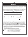 7
7
-
 8
8
-
 9
9
-
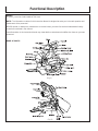 10
10
-
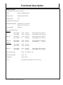 11
11
-
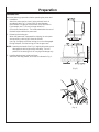 12
12
-
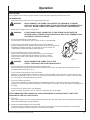 13
13
-
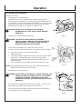 14
14
-
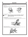 15
15
-
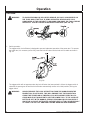 16
16
-
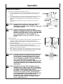 17
17
-
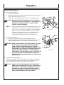 18
18
-
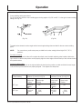 19
19
-
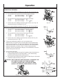 20
20
-
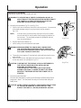 21
21
-
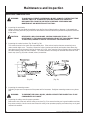 22
22
-
 23
23
-
 24
24
-
 25
25
-
 26
26
-
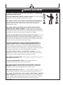 27
27
-
 28
28
-
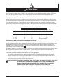 29
29
-
 30
30
-
 31
31
-
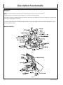 32
32
-
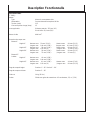 33
33
-
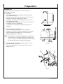 34
34
-
 35
35
-
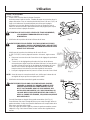 36
36
-
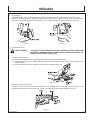 37
37
-
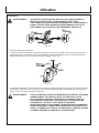 38
38
-
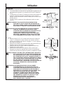 39
39
-
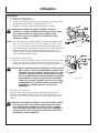 40
40
-
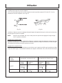 41
41
-
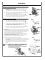 42
42
-
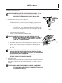 43
43
-
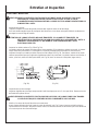 44
44
-
 45
45
-
 46
46
-
 47
47
-
 48
48
-
 49
49
-
 50
50
-
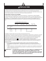 51
51
-
 52
52
-
 53
53
-
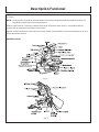 54
54
-
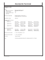 55
55
-
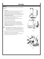 56
56
-
 57
57
-
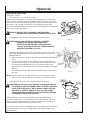 58
58
-
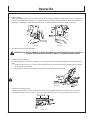 59
59
-
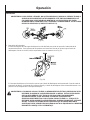 60
60
-
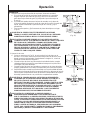 61
61
-
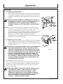 62
62
-
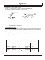 63
63
-
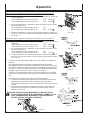 64
64
-
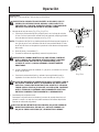 65
65
-
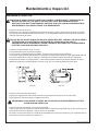 66
66
-
 67
67
-
 68
68


John Deere Saw ET-3403-J Manual de usuario
- Categoría
- Sierras de inglete
- Tipo
- Manual de usuario
- Este manual también es adecuado para
en otros idiomas
- français: John Deere Saw ET-3403-J Manuel utilisateur
- English: John Deere Saw ET-3403-J User manual
Artículos relacionados


Otros documentos
-
Craftsman 12632561 El manual del propietario
-
-
-
Genesis GMDB1215LF Manual de usuario
-
-
Hitachi C10FSBP4 El manual del propietario
-
Hitachi C10FCH2 El manual del propietario
-
-
Hitachi Koki 10FCB Manual de usuario
-
Toro Anti-Scalp Kit, GrandStand Mower Guía de instalación