
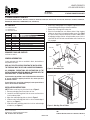
Figure 1 - Assembling Trim
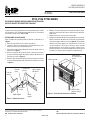
Figure 2 - Attaching Trim to Firebox
6. While fi rmly holding edges of trim together, tighten both screws
on the adjusting plate using a slotted screwdriver.
7. Repeat steps 2 through 6 for other side.
8. Place the assembled trim onto fi rebox cabinet. Align hanging
notches on trim with trim hanging shoulder screws (see Figure
2). Tap trim fi rmly into place with palm of hand or rubber mallet
by engaging hanging notches around shoulder screws. Start at
one end of the trim and work around fi rebox until all notches are
fully engaged.
Set Screws
Slot
Slot
Shim
Top Trim
Side Trim
Adjusting
Plate
Mitered
Edge
Mitered Edge
PT SERIES PERIMETER TRIM KITS
[FOR USE WITH MODELS BRT2032, BRT2532/36, BRT4036/42, BRT4336/42, BRT4536/42, VRT3032/36/42, VCT3032/36/42, VRT4032/36, VCT4032/36, ALPHA32/36,
MISSION36/42, VEGA32/36/42, CUMBERLAND32/36/42, WESTERLY32]
PT SERIES PERIMETER TRIM KITS
P/N 127149-01
Rev. B, 03/2017
HEARTH PRODUCTS
KITS AND ACCESSORIES
Cat. No. Model Description
F1039
PT32
32" Perimeter Trim - Black
F1040
PT32B
32" Perimeter Trim - Brushed Brass
F1041
PT32P
32" Perimeter Trim - Platinum
F1042
PT36
36" Perimeter Trim - Black
F1043
PT36B
36" Perimeter Trim - Brushed Brass
F1044
PT36P
36" Perimeter Trim - Platinum
F1045
PT42
42" Perimeter Trim Kit, Black
F1046
PT42B
42" Perimeter Trim Kit, Brushed Brass
F1047
PT42P
42" Perimeter Trim Kit, Platinum
KIT CONTENTS
1 ea. 3-Piece Trim Set
1 ea. Hardware Kit
1 ea. Instruction Sheet
REQUIRED TOOLS AND SUPPLIES
Flat Blade Screwdriver
GENERAL INFORMATION
3-piece perimeter trim kits are available in black, brushed brass
and platinum fi nishes.
READ ALL THE STEPS BEFORE STARTING THE INSTALLATION
THE FIREPLACE MUST BE OFF AND COLD BEFORE BEGINNING.
ALL WARNINGS, PRECAUTIONS AND INSTRUCTIONS IN THE
INSTALLATION AND OPERATION MANUAL PROVIDED WITH THE
APPLIANCE APPLY TO THESE INSTRUCTIONS.
If you encounter any problems, need clarifi cation of these instructions
or are not qualifi ed to properly install this kit, contact you local
distributor or dealer.
If any of these parts are missing or damaged, contact your dealer or
IHP.us.com for referral information.
INSTALLATION INSTRUCTIONS
NOTE: Firebox model may vary from that shown in Figure 2.
1. Remove packaging from three pieces of trim.
2. Locate the two adjusting plates with set screws and two shims
in the hardware packet.
3. Align shim under adjusting plate as shown in Figure 1.
4. Slide one end of adjusting plate/shim in slot on mitered edge of
top trim (see Figure 1).
5. Slide other end of adjusting plate/shim in slot on mitered edge
of side trim (see Figure 1).
Trim Hanging Shoulder
Screw Locations
Assembled Trim
Hanging Notches
on Trim
Printed in U.S.A. © 2014 Innovative Hearth Products
P/N 127149-01 Rev. B 03/2017
IHP reserves the right to make changes at any time, without notice, in design, materials, specifi cations, prices and also to discontinue colors, styles and products. Consult your local distributor for
fi replace code information. IHP
1508 Elm Hill Pike, Suite 108 • Nashville, TN 37210
IHP.us.com 1

PT32, PT36 Y PT42 SERIES
DE JUEGO DE ADORNO INSTRUCCIONES DE INSTALACIÓN
INCLUYE PAQUETE DE FERRETERÍA 102865-01
Figura 1 - Armado del adorno
INSTRUCIONES DE INSTALACI
Ó
N
Nota: El modelo de chimenea puede ser distinto al ilustrado en la
Figura 2.
1. Retire el embalaje de las tres piezas de adorno.
2. Localice las dos placas de ajuste con su juego de tornillos, y dos
bases para nivelar en el paquete de piezas.
3. Alinee la base para nivelar debajo de la placa de ajuste como se
muestra en la Figura 1.
4. Deslice un extremo de la placa de ajuste y base para nivelar en
la ranura del borde angular de la parte superior del adorno de la
chimenea (consulte la fi gura 1).
5. Deslice el otro extremo de la placa de ajuste y base para nivelar en
la ranura del borde angular del adorno de la chimenea (consulte
la fi gura 1).
Figura 2 - Colcación del adorno en la chimenea
6. Mientras sostiene fi rmemente los bordes del adorno juntos,
apriete los dos tornillos de la placa de ajuste con un destornil-
lador plano.
7. Repita los pasos 2 a 6 para armar el otro lado.
8. Ponga el ensamblaje del adorno en el gabinete de la chimenea.
Alinee las muescas del adorno con los tornillos con pivote pro-
vistos para colgar el adorno (consulte la fi gura 2). Fije el adorno
dándole unos lijeros golpes con la palma de la mano o con
un mazo de goma, hasta que las muescas hayan entrado
completamente en los tornillos con pivote. Empiece en un
extremo del adorno y continúe alrededor de la chimenea hasta
que todas las muescas estén ocupadas completamente.
Tornillos de
presión
Ranura
Ranura
Base para
nivelar
Parte superior
del adorno
Lado del
adorno
Placa de
ajuste
Borde angular Borde
angular
Si alguna pieza falta o está dañada, llame al proveedor que le vendió
este paquete o a IHP. También puede puede visitar el sitio web de
servicio técnico de IHP en IHP.us.com.
Ubicación de
los tornillos con
pivote
Muescas para
colgar el adorno
Adorno armado
PT32, PT36 Y PT42 SERIES
P/N 127149-01
Rev. B, 03/2017
HEARTH PRODUCTS
KITS AND ACCESSORIES
Printed in U.S.A. © 2014 Innovative Hearth Products
P/N 127149-01 Rev. B 03/2017
IHP se reserva el derecho de modifi car, en cualquier momento y sin previo aviso el diseño, los materiales, las especifi caciones y los precios, así como también discontinuar colores, estilos y productos.
Consulte a su distribuidor local para obtener información sobre los códigos del calentador. IHP
1508 Elm Hill Pike, Suite 108 • Nashville, TN 37210
IHP.us.com
2
-
 1
1
-
 2
2


Astria Fireplaces BRT40 Instruction Sheet
- Tipo
- Instruction Sheet
en otros idiomas
- English: Astria Fireplaces BRT40