Audibax Zone 360 BT El manual del propietario
- Categoría
- Amplificadores de audio para automóviles
- Tipo
- El manual del propietario

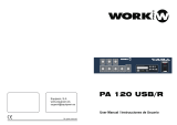
Zone 120BT / Zone 240BT / Zone 360BT
Please read the manual before using the product
USER´S
MANUAL
15
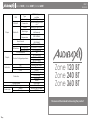
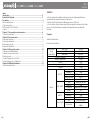
Zone 120 BT
Zone 240 BT
Zone 360 BT
Player
USB Type
OTG2.0 full-speed
controller
Connectors
USB 2.0 Type-A
SD/MMC Connectors
Non-self-locking so card
slot
Bluetooth
Version
Bluetooth Ver20+EOR
Max range
10m (without
interference)
Trans
Frequencies
2402-2480MHz
Music formats
MP3/WAW/WMA/FLAC
(8/16/24bit)
File system
FAT16 or FAT32
FM Section
Tuning range
87.5MHz to 107.9MHz
Antenna input
75Ω unbalanced
Outputs
Low impedance
4Ω
Constant Voltage impedance
167Ω-Zone 60BT
84Ω-Zone 120BT
42Ω-Zone 240BT
28Ω-Zone 360BT
Indicators
LED
Power/Zone/Output
LCO
Player
Sound
Protect
Protection
DC-Short Circuit
Over Healing
Over Load
Limiter
Cooling system
Fan cooled
Amplifier technology
Class A/B
Power supply
Master
AC230V-240V/50-60Hz
Standby
DC24V

Zone 120BT / Zone 240BT / Zone 360BT USER´S
MANUAL
1 14
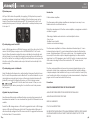
Index
Introduction..................................................................................................................2
System Black Diagram................................................................................................2
Precautions...................................................................................................................2
Safety requirements......................................................................................................2
Caution servicing..........................................................................................................3
EC Declaration of Conformity.....................................................................................3
Caution..........................................................................................................................4
Chapter 1: Pin connections and connectors............................................................4
Connection standards.................................................................................................4
Chapter 2: Front & rear panel.....................................................................................5
Front panel overview....................................................................................................5
Front panel description.................................................................................................5
Rear panel overview.....................................................................................................8
Rear panel description.................................................................................................8
Chapter 3: Setting up the system..............................................................................10
Connection the loudspeakers...................................................................................11
Connection the audio sources..................................................................................12
Phantom power..........................................................................................................13
To start playing music form MP3................................................................................13
To start playing music via Bluetooth .........................................................................13
Chapter 4: Additional information............................................................................14
Technical specifications.............................................................................................14
ATTENTION
• Do not operate the amplifier or disconnect power cable during firmwave
update Firmware update takes about10seconds
• No files other than firmware in USB storage device or SD card.
• Do not perform this procedure unless firmware update is necessary Also make
sure you read the information supplied with updates before updating the
firmware.
Chapter 4
Additional information
Technical specifications
RMS Output
Power
1 kdiE.TriD %o
Zone 120BT
120 Watt
Zone 240BT
240 Watt
Zone 360BT
360 Watt
Frequency response
20Hz-20KHz
Signal to Noise Ratio
>90dB
THD+N
<0.5%
Common Mode Rejection
<0.5%
Crosstalk
>70dB
Inputs
MiC1-2
Type
2x Balanced mic / Une
Sensitivity
-50dB
Connectors
2xXLR/6.3mmJack combo
Phantom power
15VDO
Priority
Yes
LINE 1/MIG3
Type
Balanced mic/line
Sensitivity
-50dB
Connectors
XLBi6.3mm Jack combo
Priority
YES
LINE2-3
Type
2x Stereo ling
Sensitivity
-30dB
Connectors
2x RCA
Chime/Fire/TEL
Type
Priority mic inputs
Connectors
Euro terminal block-
5.08mm

Zone 120BT / Zone 240BT / Zone 360BT USER´S
MANUAL
13 2
Introduction
Public address amplifiers
The Zone series public address amplifier was developed as an easy to use,
flexible solution for multifunctional use
During the development of the Zone series amplifiers, our engineers wanted to
achieve four goals:
-Delivering a flexible audio solution to control multiple functions
- Easy to use
-Excellent sound quality
-Modern and advanced design
The Zone series amplifiers has 2 stereo unbalanced line level inputs, 1 mono
balanced line level inputs, 2 mono balanced line level inputs with phantom
power, 4 high impedance 100V mono output zones, 1 low impedance 4ohm
mono output zone a link output a telephone signal input, a chime and fire
signal input, an 100V emergency input with 24V control, a lossless music player
with screen, including FM tuner, the model with a "+BT" version also has
bluetooth.
The Zone series amplifiers can be used in commercial applications such as
restaurants, hotels, shops, warehouses, professional offices, public buildings.….
A simple example: when installed in a shop you could connect a tuner to play
your favorite radio station, microphone to make announcements, a telephone
pager. and off course the doorbell of the shop.
Precautions
READ FOLLOWINGINSTRUCTIONS FOR YOUR OWN SAFETY
ALWAYS KEEP THESE INSTRUCTIONS NEVER THROW THEM AWAY
ALWAYS HANDLE THIS UNIT WITH CARE
HEED ALL WARNINGS
FOLLOW ALLINSTRUCTIONS
NEVER EXPOSE THIS EQUIPMENT TO RAINMOISTUREANY DRIPPING ORSPLASHING
LIQUID.AND NEVER PLACE AN OBJECT FILLED WITH LIQUID ON TOP OF THIS
DEVICE
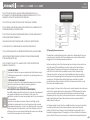
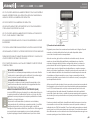
3)Phantom power
MlC input 1&2contain the possibility for supplying 15Volts phantom power for
powering condenser microphones. Enabling of the phantom power can be
done by the switches located between MIC 1&2 connections. Switch 2 will
enable phantom power to Mic input 1while switch 1 enables phantom power
to Mic input 2.
4)To start playing music form MP3
Insert a USB storage device or SD/MMC memory card to the slots on front of the
device. The MP3 player can play such as MP3WMAWAVFLAC. AAC audio
formats When the media is inserted the device will detect automatically and
will start playing You can select the playing tracks using the control buttons on
front of the device. For switching to settings of another media source, press the
M button on front (The variable audio output will switch automatically to this
media source)
5)To start playing music via Bluetooth
Adjust the bluetooth antenna to a vertical position then press the M button on
front to switch the operation mode to Bluetooth. Turn on the bluetooth on your
device(phone computer, Ipad, mace or other music playback devices with
bluetooth) and search for bluetooth device, you’ll find a device named
“ ”Bluetooth" in the list, select and connect it. Then you can
play music on your device. pressing the to control the music track previous,
next or pause.
6)Update the player's firmware
New firmware that provides additional features or product improvements will
be released as needed. You can download the type MVA of firmware from our
website.
Format the USB storage device or SD card for upgrade firs. Insert a USB storage
device or SD card with firmware on the front if the player detects firmware, it
will automatically extinguish the LCD screen and start to upgrade the firmware,
it will restart about 10 seconds later.

Zone 120BT / Zone 240BT / Zone 360BT USER´S
MANUAL
3 12
DO NOT PLACE THIS UNIT IN AN ENCLOSED ENVIRONMENT SUCH AS A
BOOKSHELF OR CLOSET ENSURE THERE IS ADEQUATE VENTILATION TO COOL
THEUNITDO NOTBLOCK THE VENTILATION OPENINGS
DO NOT STICK ANY OBJECTS THROUGH THE VENTILATION OPENINGS
DO NOT INSTALL THIS UNIT NEAR ANY HEAT SOURCES SUCH AS RADIATORS OR
OTHER APPARATUS THAT PRODUCE HEAT
DO NOT PLACE THIS UNIT IN ENVIRONMENTS WHICH CONTAIN HIGHLEVELS OF
DUST HEATMOISTURE ORVIBRATION
THIS UNIT IS DEVELOPED FOR INDOORUSE ONLYDONOT USEITOUTDOORS
PLACE THE UNIT ON A STABLE BASE OR MOUNTITIN A STABLE RACK
ONLY USE ATTACHMENTS & ACCESSORIES SPECIFIED BY THE MANUFACTURER
UNPLUG THIS APPARATUS DURING LIGHTNING STORMS ORWHEN UNUSED
FORLONG PERIODS OF TIME
ONLY CONNECT THIS UNIT TO A MAINS SOCKET OUTLET WITH PROTECTIVE
EARTHING CONNECTION
CAUTION-SERVICING
This product contains no user serviceable parts. Refer all servicing to
qualified service personnel. Do not perform any servicing (unless you
are qualified to)
EC DECLARATION OF CONFORMITY
This product conforms to all the essential requirements and further
relevant specifications described in following directives:
2004/108/EC(EMC) and 2006/95/EC(LVD)
WASTE ELECTRICAL AND ELECTRONIC EQUIPMENT(WEEE)
The WEEE marking indicates that this product should not be disposed
with regular household waste at the end of its life cycle. This
regulation is created to prevent any possible harm to the environment
or human health.
This product is developed and manufactured with high quality
materials and components which can be recycled and/or reused
Please dispose this product at your local collection point or recycling
center for electrical and electronic waste. This will make sure that it
will be recycled on an environmentally friendly manner, and will help
to protect the environment in which we all live.
2) Connecting the audio sources
The next step is making the signal input connections. Depending of the type
connection and output level of the available audio sources they should be
plugged into the matching channel/connection.
Before connecting, turn all the channel input and master volume controls on
the front panel of the amplifier fully counter clockwise (to their minimum
setting) and put the gain control trimmers on the rear panel in a central
position. Then connect all the available sources to their corresponding
channels and switch on the power of the amplifier and al the connected
audio sources the green light around the power button will illuminate after
powering on. The buzzer inside will ring three times and then the output
protection relay will be switched on (a click will be heard when this occurs)
that mean the amplifier is ready.
Apply a signal to the inputs as it will be used in normal operation circumstances
and turn the channel input level control up about 50%Slowlyraise the master
volume control till a certain level until the desired sound level is achieved
Depending of the output level of the connected music sources the input gain
might need adjustment Adjust these trimmers on the rear panel until the
desired level is achieved.
For the best signal to noise ratio, the amplifier should run in normal circumstan-
ces with the master level control near maximum position and the peak
indicator (0 dB) of the VU meter on front should light occasionally (but not
frequently during peak levels. If the signal is too loud or distorted use the input
level controls to attenuate as necessary to achieve the desired speaker level.

4
Zone 120BT / Zone 240BT / Zone 360BT USER´S
MANUAL
11
CAUTION
The symbols shown are internationally recognized symbols that warn about
protentional hazards of electrical products. The lightning flash with arrow point
in an equilateral triangle means that the unit contains dangerous voltages. The
exclamation point in an equilateral triangle indicates that it is necessary for the
user to refer to the user manual.
These symbols warn that there are no user serviceable parts inside the unit. Do
not open the unit Do not attempt to service the unit yourself. Refer all servicing
to qualified personnel. Opening the chassis for any reason will void the
manufacturer's warranty. Do not get the unit wet. If liquid is spilled on the unit
shut it off immediately and take it to a dealer for service. Disconnect the unit
during storms to prevent damage.
Chapter 1
Pin connections and connectors
CONNECTION STANDARDS
The in and output connections for our audio equipment are performed
corresponding to international wiring standards for professional audio
equipment.
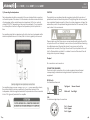
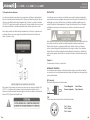
RCA(Cinch):
For unbalanced line input
Tip: Signal Sleeve: Ground
White: Left Red: Right
1) Connecting the loudspeakers
The loudspeakers should be connected to the euro terminal block connectors
on the back panel of the device. First the decision should be made which kind
of loudspeakers will be used between low impedance (4 Ohm) or constant
voltage(100V/70V/) depending on the project requirements. It is only possible
to use one (either constant voltage or low impedance) of both options at a
time
For operating using the low impedance (4 ohm) output any loudspeaker with a
minimum impedance load of 4 ohms (that is 4 ohms or greater) can be used.
For operating using constant voltage (100V/70V/…) audio distribution systems,
the positive output should be connected to the positive terminal of the
loudspeakers, while the negative terminal of the speaker should be connected
to the COM (ground) terminal of the amplifier.
Pin 1: Ground
Pin 2: Signal+
Pin 3: Signal-
XLR:
For balanced signal input connections

Zone 120BT / Zone 240BT / Zone 360BT USER´S
MANUAL
5 10
Chapter 3
Setting up the system
ATTENTION
Make sure the power of the device is turned OFF before any connections or
wiring adjustments are made. Disregarding this rule can lead to permanent
damage of the equipment.
Unbalanced line inputs 2 & 3 (RCA jack):
Line inputs 2 and 3 are implemented using RCA jack
connections it can be made a stereo line input red for right
channel white for left channel.
Chime &Fire inputs (Terminal block):
Chime &Fire inputs can be connected to any external source,
such as call station, signal matrix, fire alarm system. These
channels have priority over other inputs.
Tel input (Terminal block):
The amplifier can be connected to any business telecom
system using the tel input, allowing announcements to be
made from any handset. It is a line level input with priority to be
connected to the line output of the telecom system.
Unalanced input connections should be made to the 'CH’ (Hot
or Signal) and GND (Ground) terminals.
Emergency input (Terminal block):
The amplifier can be connected to any100Vconstantvoltage
amplifier output of alarm system with DC 24V remote control
using the emergency input. When the DC 24V is input the
amplifier will switch the all connected speakers (just constant
voltage output) to the alarm input.
Tip: Signal+
Ring: Signal-
Sleeve: Ground
6.3mm (1/4) balanced Jack:
For balanced line in & output connections.
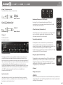
Chapter 2
Front & rear panel
Front panel overview
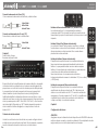
Front panel description
The front panel for Zone series amplifiers is identical and enables you to
control the level for every input and the overall output volume. A two
band tone control is provided for the main output, allowing adjustment of
the overall system frequency response while zone (output) switches allows
enabling/disabling of the different speaker zone outputs each zone
output has a separate volume control. The music player can play such as
MP3,WMA,WAV,FLAC AAC and other formats of digital music the model
with “+BT" also lets you can play music from your smartphone or
computer via bluetooth 2.0.
Input level controls
Using the input level controls, the individual level for each connected
input can be set This way, multiple inputs can be mixed with each other
between zero and maximum level.
Tip: Signal
Sleeve: Ground
6.3 mm (1/4”) unbalanced Jack:
For unbalanced line in & output

6
Zone 120BT / Zone 240BT / Zone 360BT USER´S
MANUAL
9
Chime:
When the chime button is pressed the selected chime tone as
pre-announcement for paging will be played once.
Fire:
When the fire button is pressed the fire alarm goes through the loop until the
fire button is pressed again.
Two band tone control:
Using the bass and treble rotary dials, the overall system frequency response
can be adjusted within a range of+12dB. The level will be increased while
clockwise rotating. while counter-clockwise will result in a level decrease. In
center position, both dials are set to neutral level.
Microphone echo control:
Articulated echo effect suitable for microphone channel
Master volume control:
Using the master volume control the overall system volume will be adjusted in a
range between minimum and maximum level
Digital Music player:
This is an Al-In-One Digital audio source device accommodates three different
kinds of audio sources into one single device. It including a lossless
MP3plaverFM tuner Bluetooth (+BT model only), the MP3 player can play such
as MP3,WMA,WAV,FLAC ,AAC audio formats on the front side is a graphic LCD
display screen, an USB slot a SD/MMC memory card slot and 8 control buttons
provided.
Button Function
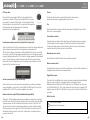
Loudspeaker output connections (Terminal block connectors)
Output connections for both low impedance and constant voltage distributed
audio systems are provided The low impedance loudspeaker and
100Vconstant voltage output share a 4-PIN terminal block, the two on the left
are used to connect low impedance speakers the two on the right are used to
connect high impedance (iust100V constant voltage) speakers. While different
zone (1-4) outputs are provided on a8-pin terminal block connector More
information about loudspeaker output connections is described in a further
chapter of this instruction manual.
Link out connections (RCA jack connectors):
These connections can be used when expanding your system by adding a
second amplifier in your system. Connect LINE2 or LINE3 input of the second
amplifier with the OUT of the master amplifier in your setup.
Balanced line1/mic inputs12&3(combination63mmjack&XLR):
Channels1, 2 & 3areimplemented using combination connectors accepting
both XLR and 6.3 mm jack plugs. Both inputs will mute all other channels when
a signal is present on the connected microphones / inputs / Mic input 1 & 2
can be used for capacitive microphones phantom power switches enable
24Vots phantom power supply for 12V-48V capacitive microphone. Switch 2
will enable phantom power to Mic input 1while switch 1 enables phantom
power to Mic input 2.
DC Power inlet:
The main DC power supply (24V) has to be applied to the
connector on the left of the AC power inlet. This is a standby
power inlet to connect a24V battery. A fuse holder with main
fuse is located on the top of the DC power inlet. When replace
the fuse make sure the replacement matches the
specifications of the original fuse.
Press: Turn on the player
Press & Hold: Turn off the player
Switch the operation mode between USBSD/MMC Bluetooth

Zone 120BT / Zone 240BT / Zone 360BT USER´S
MANUAL
7 8
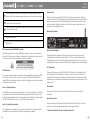
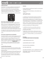
USB connection port &SD/MMC card slot:
An USB storage device and/or an SD/MMC memory card can be inserted to
these slots. Tracks stored on here can be played through the player and it will
automatically start to play when the medium is inserted.
LED indicators:
The current system operation is indicated on the 6digit LED bar graph The LED's
monitor the current output eve within a range of-18 dB and 0 dB while the
upper LED (red) illuminates when the output is clipping you need to reduce the
channel or master volume.
Zone 1-4(output)switches:
The different connected loudspeaker lines (1-4) can be switched on and off by
pressing the switches with the corresponding numbers when the zone (1-4) is
enabled the green light on the corresponding switch will be illuminated. When
the 'All switch is pressed, all zone (1-4) outputs will be enabled
Zone 1-4 (output) level control:
The output level of different zone (1-4) can be adjust within a range of-15dB
and 0dB by the band switches with the corresponding numbers.
Power switch:
The device can be switched ON and Off using the power switch. When the
device is switched ON, the green light around the power button will illuminate.
After powering on the buzzer inside will ring three times and then the output
protection relay will be switched on (a click will be heard when this occurs)
that mean the amplifier is ready.
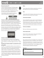
Rear Panel Overview
Rear panel description
The rear panel for amplifiers is identical and contains all connection and
configuration controls (the model without “+BT" has no bluetooth antenna).
Configuration controls include the settings which should be made once when
setting up the system and doesn’t have to be changed by the user afterwards.
AC Power inlet:
The main AC power supply (230~240VAC/50~60 Hz) has to be applied to this
AC power inlet. The connection is made by an IEC C14 power connector A
fuse holder with main fuse is located on the right of the AC power inlet. When
replace the fuse make sure the replacement matches the specifications of the
original fuse.
FM antenna:
When using an FM radio, pull out the FM antenna to ensure a good FM
reception.
Bluetooth antenna:
When connecting the bluetooth adjust the bluetooth antenna to a vertical
position to ensure a good wireless signals and longer distance.
**Only the model with '+BT has a bluetooth antenna**
Press: Started and paused for track when in USB/SD/MMC/Bluetooth Mode
Press & Hold: Automatically scanning FM radio, store it when in FM tuner Mode
Previous track when in USB/SD/MMC/Bluetooth Mode Previous stored FM radio
station when in FM tuner Mode
Next track when in USB/SD/MMC/Bluetooth Mode Next stored FM radio station
when in FM tuner Mode
Increase player volume
Reduce player volume
Switch the repeat mode between Repeat One. Repeat Folder, Repeat All and
Repeat Off

Zone 120BT / Zone 240BT / Zone 360BT
Por favor, lea el manual antes de usar el producto
MANUAL
DE USUARIO
15
Zone 120 BT
Zone 240 BT
Zone 360 BT
Reproductores
USB Tipo
Controlador de velocidad
completa OTG2.0
Conectores
USB 2.0 tipo A
SD/MMC Conectores
Ranura para tarjeta sin
autobloqueo
Bluetooth
Versión
Bluetooth Ver20+EOR
Rango máximo
10m (sin interferencia)
Frecuencias Trans
2402-2480MHz
Formatos de música
MP3/WAW/WMA/FLAC
(8/16/24bit)
Sistema de archivos
FAT16 or FAT32
Sección FM
Rango de sintonía
87.5MHz to 107.9MHz
Entrada de
antena
75Ω no balanceado
Salidas
baja impedancia
4Ω
Impedancia de voltaje constante
167Ω-Zone 60BT
84Ω-Zone 120BT
42Ω-Zone 240BT
28Ω-Zone 360BT
Indicadores
LED
Potencia/Zona/Salida
LCO
Jugador
Sonido
Proteger
Proteccion
DC-Short: circuit
Sistema de refrigeración
Refrigerado por ventilador
Tecnología de amplificador
Clase A/B
Fuente de
alimentación
Maestro
AC230V-240V/50-60Hz
Apoyar
DC24V
Over Healing
Over Load
Limiter

Zone 120BT / Zone 240BT / Zone 360BT MANUAL
DE USUARIO
1 14
Índice
Introducción.................................................................................................................2
Diagrama negro del sistema......................................................................................2
Precauciones...............................................................................................................2
Requisitos de seguridad...............................................................................................2
Precaución servicio......................................................................................................3
Declaración CE de conformidad...............................................................................3
Precaución....................................................................................................................4
Capítulo 1: Conexiones de clavijas y conectores....................................................4
Estándares de conexión...............................................................................................4
Capítulo 2: Panel frontal y posterior............................................................................5
Resumen del panel frontal...........................................................................................5
Descripción del panel frontal......................................................................................5
Vista general del panel trasero...................................................................................8
Descripción del panel trasero.....................................................................................8
Capítulo 3: Configuración del sistema.....................................................................10
Conexión de los altavoces........................................................................................11
Conexión de las fuentes de audio............................................................................12
Poder fantasma..........................................................................................................13
Para comenzar a reproducir música desde MP3....................................................13
Para empezar a reproducir música a través de Bluetooth....................................13
Capítulo 4: Información adicional...........................................................................14
Especificaciones técnicas.........................................................................................14
ATENCIÓN
• No utilice el amplificador ni desconecte el cable de alimentación durante la
actualización de Firmware. La actualización del firmware tarda unos 10
segundos.
• No hay archivos que no sean firmware en el dispositivo de almacenamiento
USB o tarjeta SD.
• No realice este procedimiento a menos que sea necesaria una actualiza-
ción de firmware. También asegúrese de leer la información proporcionada
con las actualizaciones antes de actualizar el firmware.
Capítulo 4
Información Adicional
Especificaciones técnicas
Potencia de
salida RMS
1 kdiE.TriD %o
Zone 120BT
120 Vatios
Zone 240BT
240 Vatios
Zone 360BT
360 Vatios
Respuesta de frecuencia
20Hz-20KHz
Signal to Noise Ratio
>90dB
THD+N
<0.5%
Common Mode Rejection
<0.5%
Diafonía
>70dB
Entradas
MiC1-2
Tipo
2x micrófono balanceado /
Une
Sensibilidad
-50dB
Conectores
Combinación de 2xXLR/Jack
de 6,3 mm
Potencia Phantonm
15VDO
Prioridad
Sí
LINE 1/MIG3
Tipo
Línea/micrófono
balanceado
Sensibilidad
-50dB
Conectores
Conector combinado
XLBi6.3mm
Prioridad
SÍ
LINE2-3
Tipo
2x audio estéreo
Sensibilidad
-30dB
Conectores
2x RCA
Chime/Fire/TEL
Tipo
Entradas de micrófono
prioritarias
Conectores
Bloque de terminales euro-
5.08mm

Zone 120BT / Zone 240BT / Zone 360BT MANUAL
DE USUARIO
13 2
Introducción
Durante el desarrollo de los amplificadores de la serie Zone, nuestros ingenieros
querían lograr cuatro objetivos:
-Ofrecer una solución de audio flexible para controlar múltiples funciones
- Fácil de usar
-Excelente calidad de sonido
-Diseño moderno y avanzado
Los amplificadores de la serie Zone tienen 2 entradas de nivel de línea no
balanceadas estéreo, 1 entrada de nivel de línea balanceada mono, 2
entradas de nivel de línea balanceada mono con alimentación phantom, 4
zonas de salida mono de 100 V de alta impedancia 1 zona de salida mono de
4 ohmios de baja impedancia, una salida de enlace, una entrada de señal
telefónica, un timbre y entrada de señal de fuego, una entrada de emergen-
cia de 100V con control de 24V, un reproductor de música sin pérdidas con
pantalla, incluye sintonizador de FM, también tiene bluetooth.
Los amplificadores de la serie Zone se pueden utilizar en aplicaciones
comerciales como restaurantes, hoteles, tiendas, almacenes, oficinas
profesionales, edificios públicos…
Un ejemplo simple: cuando se instala en una tienda, puede conectar un
sintonizador para reproducir su estación de radio favorita, un micrófono para
hacer anuncios, un localizador de teléfono. y por supuesto el timbre de la
tienda.
Precauciones
LEA LAS SIGUIENTES INSTRUCCIONES POR SU PROPIA SEGURIDAD
CONSERVE SIEMPRE ESTAS INSTRUCCIONES
MANEJE SIEMPRE ESTA UNIDAD CON CUIDADO
TENGA EN CUENTA TODAS LAS ADVERTENCIAS
SIGA TODAS LAS INSTRUCCIONES
NUNCA EXPONGA ESTE EQUIPO A LA LLUVIA, LA HUMEDAD, GOTEO O SALPICA-
DURAS DE LÍQUIDO. Y NUNCA COLOQUE UN OBJETO LLENO DE LÍQUIDO
ENCIMA DE ESTE DISPOSITIVO.
3) Alimentación Phantom
Las entradas MlC 1 y 2 contienen la posibilidad de suministrar alimentación
phantom de 15 voltios para alimentar micrófonos de condensador. La
activación de la alimentación phantom se puede realizar mediante los
interruptores ubicados entre las conexiones MIC 1 y 2. El interruptor 2 activará
la alimentación phantom en la entrada de micrófono 1, mientras que el
interruptor 1 activará la alimentación phantom en la entrada de micrófono 2.
4) Para comenzar a reproducir música desde MP3
Inserte un dispositivo de almacenamiento USB o una tarjeta de memoria
SD/MMC en las ranuras de la parte frontal del dispositivo. El reproductor de
MP3 puede reproducir como MP3WMAWAVFLAC. Formatos de audio AAC
Cuando se inserta el medio, el dispositivo lo detectará automáticamente y
comenzará a reproducir. Puede seleccionar las pistas de reproducción
usando los botones de control en la parte frontal del dispositivo. Para cambiar
a la configuración de otra fuente de medios, presione el botón M en el frente
(la salida de audio variable cambiará automáticamente a esta fuente de
medios)
5) Para comenzar a reproducir música a través de Bluetooth
Ajuste la antena bluetooth a una posición vertical y luego presione el botón M
en el frente para cambiar el modo de operación a Bluetooth. Encienda el
bluetooth en su dispositivo (computadora telefónica, iPad, Mace u otros
dispositivos de reproducción de música con bluetooth) y busque un dispositivo
bluetooth, encontrará un dispositivo llamado "Bluetooth" en
la lista, selecciónelo y conéctelo. Luego puede Reproduzca música en su
dispositivo. Presione para controlar la pista de música anterior, siguiente o
pausa.
6) Actualizar el firmware del reproductor
Se lanzará nuevo firmware que proporcione funciones adicionales o mejoras
del producto según sea necesario. Puede descargar el tipo MVA de firmware
desde nuestro sitio web.
Formatee el dispositivo de almacenamiento USB o la tarjeta SD para actualizar
primero. Inserte un dispositivo de almacenamiento USB o una tarjeta SD con
firmware en la parte frontal si el reproductor detecta firmware, apagará
automáticamente la pantalla LCD y comenzará a actualizar el firmware, se
reiniciará unos 10 segundos después.

Zone 120BT / Zone 240BT / Zone 360BT MANUAL
DE USUARIO
3 12
NO COLOQUE ESTA UNIDAD EN UN AMBIENTE CERRADO COMO UNA ESTANTERÍA O
ARMARIO ASEGÚRESE DE QUE HAYA VENTILACIÓN ADECUADA PARA ENFRIAR LA
UNIDAD NO OBSTRUYA LAS ABERTURAS DE VENTILACIÓN
NO PEGUE OBJETOS POR LAS ABERTURAS DE VENTILACIÓN
NO INSTALE ESTA UNIDAD CERCA DE FUENTES DE CALOR COMO RADIADORES U
OTROS APARATOS QUE PRODUZCAN CALOR
NO COLOQUE ESTA UNIDAD EN AMBIENTES QUE CONTENGAN ALTOS NIVELES DE
POLVO, CALOR HUMEDAD O VIBRACIONES
ESTA UNIDAD ESTÁ DESARROLLADA SÓLO PARA USO EN INTERIORES NO LA UTILICE
EN EXTERIORES
COLOQUE LA UNIDAD SOBRE UNA BASE ESTABLE O MONTE EN UNA RACK ESTABLE
USE ÚNICAMENTE ACCESORIOS Y ACCESORIOS ESPECIFICADOS POR EL FABRICANTE
DESENCHUFE ESTE APARATO DURANTE TORMENTAS ELÉCTRICAS O CUANDO NO SE
UTILICE POR PERÍODOS DE TIEMPO PROLONGADOS
SÓLO CONECTE ESTA UNIDAD A UNA TOMA DE CORRIENTE CON PROTECCIÓN DE
CONEXIÓN A TIERRA
PRECAUCIÓN-MANTENIMIENTO
Este producto no contiene piezas reparables por el usuario. Remita
todo el servicio a personal de servicio calificado. No realice ningún
servicio (a menos que esté calificado para hacerlo)
DECLARACIÓN DE CONFORMIDAD CE
Este producto cumple con todos los requisitos esenciales y otras
especificaciones relevantes descritas en las siguientes directivas:
2004/108/EC (EMC) y 2006/95/EC (LVD)
RESIDUOS DE APARATOS ELÉCTRICOS Y ELECTRÓNICOS (RAEE)
La marca WEEE indica que este producto no debe desecharse con
los residuos domésticos habituales al final de su ciclo de vida. Este
reglamento se crea para prevenir cualquier posible daño al medio
ambiente o a la salud humana.
Este producto está desarrollado y fabricado con materiales y
componentes de alta calidad que se pueden reciclar y/o reutilizar.
Deseche este producto en su punto de recogida o centro de
reciclaje local para residuos eléctricos y electrónicos. Esto asegurará
que se recicle de manera respetuosa con el medio ambiente y
ayudará a proteger el medio ambiente en el que todos vivimos.
2) Conexión de las fuentes de audio
El siguiente paso es hacer las conexiones de entrada de señal. Según el tipo de
conexión y el nivel de salida de las fuentes de audio disponibles, deben
conectarse al canal/conexión correspondiente.
Antes de conectar, gire todos los controles de entrada de canal y volumen
maestro en el panel frontal del amplificador completamente en el sentido
contrario a las agujas del reloj (hasta su configuración mínima) y coloque los
potenciómetros de control de ganancia en el panel trasero en una posición
central. Luego, conecte todas las fuentes disponibles a sus canales correspon-
dientes y encienda el amplificador y todas las fuentes de audio conectadas. La
luz verde alrededor del botón de encendido se iluminará después de encender.
el zumbador en el interior sonará tres veces y luego se encenderá el relé de
protección de salida (se escuchará un clic cuando esto ocurra), lo que significa
que el amplificador está listo.
Aplique una señal a las entradas tal como se usará en circunstancias normales de
funcionamiento y suba el control de nivel de entrada del canal aproximadamen-
te un 50 %. Suba lentamente el control de volumen maestro hasta cierto nivel
hasta lograr el nivel de sonido deseado. Dependiendo del nivel de salida del
conectado. fuentes de música, es posible que sea necesario ajustar la ganancia
de entrada Ajuste estos potenciómetros en el panel posterior hasta que se logre el
nivel deseado.
Para la mejor relación señal/ruido. el amplificador debe funcionar en circunstan-
cias normales con el control de nivel maestro cerca de la posición máxima y el
indicador de pico (0 dB) del medidor VU en el frente debe encenderse ocasional-
mente (pero no con frecuencia durante los niveles pico. Si la señal es demasiado
alta o distorsionada, use los controles de nivel de entrada para atenuar según sea
necesario para lograr el nivel de altavoz deseado.

4
Zone 120BT / Zone 240BT / Zone 360BT MANUAL
DE USUARIO
11
PRECAUCIÓN
Los símbolos que se muestran son símbolos reconocidos internacionalmente
que advierten sobre los peligros de protección de los productos eléctricos. El
relámpago con punta de flecha en un triángulo equilátero significa que la
unidad contiene voltajes peligrosos. El signo de exclamación en un triángulo
equilátero indica que es necesario que el usuario consulte el manual del
usuario.
Estos símbolos advierten que no hay piezas reparables por el usuario dentro de
la unidad. No abra la unidad. No intente reparar la unidad usted mismo.
Remita todo el servicio a personal calificado. Abrir el chasis por cualquier
motivo anulará la garantía del fabricante. No moje la unidad. Si se derrama
líquido sobre la unidad, apáguela inmediatamente y llévela a un distribuidor
para que la reparen. Desconecte la unidad durante las tormentas para evitar
daños.
Capítulo 1
Conexiones de clavijas y conectores
NORMAS DE CONEXIÓN
Las conexiones de entrada y salida de nuestros equipos de audio se realizan
de acuerdo con los estándares internacionales de cableado para equipos de
audio profesionales.
RCA (cincha):
Para entrada de línea no balanceada
Punta: Manguito Señal: Tierra
Blanco: Izquierda Rojo: Derecha
1) Conexión de los altavoces
Los altavoces deben conectarse a los conectores del bloque de terminales
euro en el panel posterior del dispositivo. Primero se debe decidir qué tipo de
altavoces se utilizarán entre baja impedancia (4 ohmios) o voltaje constante
(100 V/70 V/) según los requisitos del proyecto. Solo es posible usar una (ya sea
de voltaje constante o de baja impedancia) de ambas opciones a la vez
Para operar usando la salida de baja impedancia (4 ohmios), se puede usar
cualquier altavoz con una carga de impedancia mínima de 4 ohmios (es
decir, 4 ohmios o más).
Para operar con sistemas de distribución de audio de voltaje constante (100
V/70 V/...), la salida positiva debe conectarse al terminal positivo de los
altavoces, mientras que el terminal negativo del altavoz debe conectarse al
terminal COM (tierra) del amplificador.
Pin 1: Tierra
Pin 2: Señal +
Pin 3: Señal -
XLR:
Para conexiones de entrada de señal balanceada

Zone 120BT / Zone 240BT / Zone 360BT MANUAL
DE USUARIO
5 10
Capítulo 3
Configuración del sistema
ATENCIÓN
Asegúrese de que la alimentación del dispositivo esté APAGADA antes de
realizar cualquier conexión o ajuste de cableado. El incumplimiento de esta
regla puede provocar daños permanentes en el equipo.
Entradas de línea no balanceadas 2 y 3 (conector RCA):
Las entradas de línea 2 y 3 se implementan mediante
conexiones jack RCA; se puede convertir en una entrada de
línea estéreo roja para el canal derecho y blanca para el canal
izquierdo.
Entradas Chime & Fire (Bloque de terminales):
Las entradas Chime & Fire se pueden conectar a cualquier
fuente externa, como estación de llamada, matriz de señal,
sistema de alarma contra incendios. Estos canales tienen
prioridad sobre otras entradas.
Entrada de teléfono (bloque de terminales):
El amplificador se puede conectar a cualquier sistema de
telecomunicaciones empresarial mediante la entrada de
teléfono, lo que permite realizar anuncios desde cualquier
teléfono. Es una entrada de nivel de línea con prioridad para
conectarse a la salida de línea del sistema de
telecomunicaciones. Las conexiones de entrada no
balanceadas deben hacerse a los terminales 'CH' (vivo o señal)
y GND (tierra).
Entrada de emergencia (Bloque de terminales):
El amplificador se puede conectar a cualquier salida de
amplificador de voltaje constante de 100 V del sistema de
alarma con control remoto de 24 V CC usando la entrada de
emergencia. Cuando se ingresa la CC de 24 V, el amplificador
cambiará todos los altavoces conectados (solo salida de
voltaje constante) a la entrada de alarma.
Punta: Señal +
Anillo: Señal -
Enchufe: Tierra
Conector balanceado de 6,3 mm (1/4):
Para conexiones balanceadas de entrada y salida de línea.
Capitulo 2
Panel frontal y trasero
Resumen del panel frontal
Descripción del panel frontal
El panel frontal de los amplificadores de la serie es idéntico y le permite
controlar el nivel de cada entrada y el volumen de salida general. Se
proporciona un control de tono de dos bandas para la salida principal,
lo que permite el ajuste de la respuesta de frecuencia general del
sistema, mientras que los interruptores de zona (salida) permiten
habilitar/deshabilitar las diferentes salidas de zona del altavoz, cada
salida de zona tiene un control de volumen separado. El reproductor de
música puede reproducir MP3, WMA, WAV, FLAC AAC y otros formatos
de música digital. El modelo con "+BT" también le permite reproducir
música desde su teléfono inteligente o computadora a través de
bluetooth 2.0.
Controles de nivel de entrada
Usando los controles de nivel de entrada, se puede configurar el nivel
individual para cada entrada conectada. De esta manera, se pueden
mezclar varias entradas entre sí entre cero y el nivel máximo.
Punta: Señal
Enchufe: Tierra
Conector no balanceado de 6,3 mm (1/4”):
Para entrada y salida de línea no balanceada

6
Zone 120BT / Zone 240BT / Zone 360BT MANUAL
DE USUARIO
9
Repicar:
Cuando se presiona el botón de timbre, se reproducirá una vez el tono de
timbre seleccionado como anuncio previo para megafonía.
Fuego:
Cuando se presiona el botón de disparo, la alarma de incendio pasa por el
bucle hasta que se vuelve a presionar el botón de disparo.
Control de tono de dos bandas:
Usando los diales giratorios de graves y agudos, la respuesta de frecuencia
general del sistema se puede ajustar dentro de un rango de +12dB. El nivel
aumentará mientras gira en el sentido de las agujas del reloj. mientras que en
el sentido contrario a las agujas del reloj se producirá una disminución del
nivel. En la posición central, ambos diales se establecen en el nivel neutral.
Control de eco del micrófono:
Efecto de eco articulado apto para canal de micrófono
Control de volumen maestro:
Usando el control de volumen maestro, el volumen general del sistema se
ajustará en un rango entre el nivel mínimo y máximo.
Reproductor de música digital:
Este es un dispositivo de fuente de audio digital Al-In-One que admite tres tipos
diferentes de fuentes de audio en un solo dispositivo. Incluye un sintonizador
MP3plaverFM sin pérdidas Bluetooth (+solo modelo BT), el reproductor de MP3
puede reproducir formatos de audio como MP3, WMA, WAV, FLAC, AAC en la
parte frontal es una pantalla LCD gráfica, una ranura USB SD/MMC Ranura
para tarjeta de memoria y 8 botones de control provistos.
Botón Función
Conexiones de salida de altavoz (Conectores de bloque de terminales)
Se proporcionan conexiones de salida para sistemas de audio distribuidos de
voltaje constante y baja impedancia. El altavoz de baja impedancia y la
salida de voltaje constante de 100 V comparten un bloque de terminales de 4
pines, los dos de la izquierda se usan para conectar altavoces de baja
impedancia, los dos de la derecha se usan para conectar altavoces de alta
impedancia (voltaje constante iust100V). Mientras que las diferentes salidas de
zona (1-4) se proporcionan en un conector de bloque de terminales de 8
pines. En otro capítulo de este manual de instrucciones se describe más
información sobre las conexiones de salida de los altavoces.
Conexiones de salida de enlace (conectores jack RCA):
Estas conexiones se pueden usar al expandir su sistema agregando un
segundo amplificador en su sistema. Conecte la entrada LINE2 o LINE3 del
segundo amplificador con la SALIDA del amplificador maestro en su configura-
ción.
Línea balanceada 1/entradas de micrófono 12 y 3 (combinación de conector
de 63 mm y XLR):
Los canales 1, 2 y 3 se implementan mediante conectores combinados que
aceptan conectores XLR y jack de 6,3 mm. Ambas entradas silenciarán todos
los demás canales cuando haya una señal presente en los micrófonos /
entradas conectados / La entrada de micrófono 1 y 2 se puede usar para
micrófonos capacitivos Los interruptores de alimentación fantasma permiten
una fuente de alimentación phanton de 24 V para micrófono capacitivo de
12 V-48 V El interruptor 2 habilitará la alimentación phantom en la entrada de
micrófono 1, mientras que el interruptor 1 habilitará la alimentación phanton
en la entrada de micrófono 2.
Entrada de alimentación de CC:
La fuente de alimentación principal de CC (24 V) debe aplicarse
al conector a la izquierda de la entrada de alimentación de CA.
Esta es una entrada de energía de reserva para conectar una
batería de 24V. Un portafusibles con fusible principal se encuentra
en la parte superior de la entrada de alimentación de CC.
Cuando reemplace el fusible, asegúrese de que el reemplazo
coincida con las especificaciones del fusible original.
Presione: Encienda el reproductor
Mantener pulsado: apagar el reproductor
Cambiar el modo de operación entre USBSD/MMC Bluetooth

Zone 120BT / Zone 240BT / Zone 360BT MANUAL
DE USUARIO
7 8
Puerto de conexión USB Ranura para tarjeta SD/MMC:
Se puede insertar un dispositivo de almacenamiento USB y/o una tarjeta de
memoria SD/MMC en estas ranuras. Las pistas almacenadas aquí se pueden
reproducir a través del reproductor y comenzará a reproducirse
automáticamente cuando se inserte el medio.
Indicadores LED:
El funcionamiento actual del sistema se indica en el gráfico de barras LED de 6
dígitos. Los LED monitorean la salida actual dentro de un rango de -18 dB y 0
dB, mientras que el LED superior (rojo) se ilumina cuando la salida se está
saturando y necesita reducir el canal o el volumen maestro.
Interruptores de zona 1-4 (salida):
Las diferentes líneas de altavoces conectadas (1-4) se pueden encender y
apagar pulsando los interruptores con los números correspondientes cuando
la zona (1-4) esté habilitada se encenderá la luz verde del interruptor
correspondiente. Cuando se presiona el interruptor 'All', todas las salidas de
zona (1-4) se habilitarán
Control de nivel de zona 1-4 (salida):
El nivel de salida de las diferentes zonas (1-4) se puede ajustar dentro de un
rango de -15dB y 0dB mediante los interruptores de banda con los números
correspondientes.
Interruptor de alimentación:
El dispositivo se puede encender y apagar con el interruptor de encendido.
Cuando el dispositivo está encendido, la luz verde alrededor del botón de
encendido se iluminará. Después de encender, el zumbador interno sonará
tres veces y luego se encenderá el relé de protección de salida (se escuchará
un clic cuando esto ocurra), lo que significa que el amplificador está listo.
Vista general del panel trasero
Descripción del panel trasero
El panel posterior de los amplificadores de la serie son idénticos y contienen
todos los controles de conexión y configuración (el modelo sin "+BT" no tiene
antena bluetooth). Los controles de configuración incluyen los ajustes que
deben realizarse una vez al configurar el sistema y no t tiene que ser cambia-
do por el usuario después.
Entrada de alimentación de CA:
La fuente de alimentación de CA principal (230~240 VCA/50~60 Hz) debe
aplicarse a esta entrada de alimentación de CA. La conexión se realiza
mediante un conector de alimentación IEC C14. Un portafusibles con fusible
principal se encuentra a la derecha de la entrada de alimentación de CA.
Cuando reemplace el fusible, asegúrese de que el reemplazo coincida con
las especificaciones del fusible original.
Antena FM:
Cuando utilice una radio FM, extraiga la antena FM para garantizar una
buena recepción de FM
Antena Bluetooth:
Al conectar el bluetooth, ajuste la antena bluetooth a una posición vertical
para garantizar una buena señal inalámbrica y una mayor distancia
**Solo el modelo con '+BT tiene antena bluetooth**
Presione: Iniciado y pausado para la pista cuando está en modo
USB/SD/MMC/Bluetooth
Mantenga presionado: escanea automáticamente la radio FM, guárdela
cuando esté en el modo de sintonizador FM
Pista anterior cuando está en modo USB/SD/MMC/Bluetooth Estación de radio
FM almacenada anteriormente cuando está en modo de sintonizador FM
Pista siguiente cuando está en modo USB/SD/MMC/Bluetooth Siguiente
estación de radio FM almacenada cuando está en modo de sintonizador FM
Aumentar el volumen del reproductor
Reducir el volumen del reproductor
Cambia el modo de repetición entre Repetir uno. Repetir carpeta,
Repetir todo y Repetir desactivado
-
 1
1
-
 2
2
-
 3
3
-
 4
4
-
 5
5
-
 6
6
-
 7
7
-
 8
8
-
 9
9
-
 10
10
-
 11
11
-
 12
12
-
 13
13
-
 14
14
-
 15
15
-
 16
16


Audibax Zone 360 BT El manual del propietario
- Categoría
- Amplificadores de audio para automóviles
- Tipo
- El manual del propietario
en otros idiomas
- English: Audibax Zone 360 BT Owner's manual