Optimus A-5230M2 Manual de usuario
- Categoría
- Reproductores de CD
- Tipo
- Manual de usuario
Este manual también es adecuado para

AMPLIFICADOR CON
FUENTES MUSICALES
AMPLIFIER WITH
MUSIC SOURCES
A-5230M2
A-5260M2

A-5230M2 / A-5260M2 Versión 1.1
A-5230M2 / A-5260M2
Amplificador
INSTRUCCIONES DE SEGURIDAD:
IMPORTANTE
Los códigos de color de los cables de red
son los siguientes:
INSTALACIÓN GENERAL
¾ NO PASAR los cables de micrófono cerca de cables de red, informáticos, telefónicos o de
línea de 100 V.
¾ NO PASAR los cables de línea de 100 V cerca de cables informáticos, telefónicos o de baja
tensión.
¾ NO SOBREPASAR el 90 % de la potencia de salida de los amplificadores cuando se utiliza
línea de 100 V para avisos.
¾ NO SOBREPASAR el 70 % de la potencia de salida de los amplificadores cuando se utiliza la
línea de 100 V para música ambiental a alto volumen.
¾ NO UTILIZAR altavoces exponenciales para música ambiental, excepto si éstos han sido
especialmente diseñados para esta función.
¾ NO HACER empalmes en los cables de micrófono. Si es inevitable, utilizar exclusivamente
conectores blindados de buena calidad, como los XLR.
¾ UTILIZAR SIEMPRE micrófonos balanceados de baja impedancia o aislados de la masa
conectados a entradas balanceadas si los cables son muy largos.
¾ UTILIZAR SIEMPRE un cable doble aislante de calidad equivalente a los de la red de baja
tensión para las conexiones de los altavoces.
¾ ASEGURARSE de que todos los altavoces están en fase.
¾ ASEGURARSE de que no existe ningún cortocircuito en la línea de altavoces antes de
conectarla al amplificador.
Verde y amarillo Tierra (E)
Azul Neutro (N)
Marrón Positivo (L)
Si los colores de los cables de red de este aparato
no se corresponden con las marcas de sus
terminales de conexión, debe procederse como
sigue:
Conectar el cable de color verde y amarillo al
terminal marcado con la letra E o con el símbolo de
tierra. Conectar el cable de color azul al terminal
negro o marcado con la letra N. Conectar el cable
de color marrón al terminal rojo o marcado con la
letra L.
Si se usa un conector macho de 13 A (BS1363), o
de cualquier otro tipo, debe colocarse un fusible de
5 A en el conector o en la caja de distribución.

A-5230M2 / A-5260M2 Versión 1.1
A-5230M2 / A-5260M2
Amplificador
1. PANEL FRONTAL....................................................................................................... 1
2. PANEL POSTERIOR................................................................................................... 1
3. MÓDULO TUNER AM/FM (TM-3) ............................................................................... 2
4. MÓDULO CD/MP3 (CD-5)........................................................................................... 2
5. DIAGRAMA DE BLOQUES......................................................................................... 3
6. CONEXIONES ............................................................................................................. 4
6.1. CONEXIÓN DE ALIMENTACIÓN .....................................................................................4
6.2. CONEXIÓN BATERÍA (24 VCC).......................................................................................4
6.3. CONEXIÓN DE LOS MICRÓFONOS................................................................................4
6.4. GONG ................................................................................................................................5
6.5. CONEXIÓN TELEFÓNICA (TEL)......................................................................................5
6.6. CONEXIÓN DE SALIDA MOH (MUSIC ON HOLD)..........................................................5
6.7. CONEXIÓN A OTRAS FUENTES DE SEÑAL (AUX).......................................................5
6.8. CONEXIÓN A LAS SALIDAS BOOSTER.........................................................................6
6.9. CONEXIÓN A LOS ALTAVOCES.....................................................................................6
6.9.1. Línea de 100V .........................................................................................................................6
6.9.2. Líneas de 70 V y 25 V.............................................................................................................6
6.9.3. Baja impedancia (8 Ω)............................................................................................................6
7. FUNCIONAMIENTO DEL REPRODUCTOR DE CD ................................................... 7
8. FUNCIONAMIENTO DEL TUNER............................................................................... 7
9. ESPECIFICACIONES TÉCNICAS............................................................................... 8
9.1. AMPLIFICADOR CON FUENTES MUSICALES (A-5230M2 / A-5260M2).......................8
9.2. UNIDAD REPRODUCTORA DE CD/MP-3 (CD-5)............................................................9
9.3. UNIDAD DE TUNER DIGITAL AM / FM (TM-3)................................................................9

A-5230M2 / A-5260M2 Versión 1.1 Página 1 de 9
Amplificador
A
-5230M2 / A-5260M2
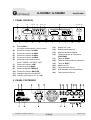
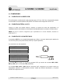
1. PANEL FRONTAL
PUBLIC ADDRESS AMPLIFIER WITH MUSCI SOURCE
0 dB
- 6
- 20
ZONE 2ZONE 1
12 3 4 5 6 7 8 9 10 11
232221201918171615141312
(1) Entrada MIC1
(Conector hembra jack 6,3 mm 3 polos)
(2) Control de volumen de MIC1
(3) Control de volumen de MIC2
(4) Control de volumen de MIC3
(5) Control de volumen de MIC4
(6) Selección de la fuente musical
(AUX / TUNER / CD-TAPE / OFF)
(7) Control de volumen LINE
(8) Control de graves BASS
(9) Control de agudos TREBLE
(10) Control de volumen MASTER
(11) Interruptor de potencia ON/OFF
(12) Vumeter (LED’s para -20, -6, 0 dB)
2. PANEL POSTERIOR
+24V 0 COM 8 25V 70V 100V
Ω
DC INPUT
115V~ 230V~
COM 100V COM 100V
ZONE 1 ZONE 2
FM AM
ANT
LINE
OUT
AUX
L
R
600 1V 8 1W MUTE G COM HOTΩΩ
MOH
OUTPUT LEVEL
TEL
INPUT LEVEL
MIC 1MIC 2MIC 3MIC 4
BALANCED
(13) Display del Tuner
(14) Selectores de Memoria
(15) Selector de banda AM/FM
(16) Teclas de ajuste de Frecuencia
(UP/DOWN)
(17) Tecla de SCAN
(18) Tecla de confirmación de memorias
(19) Tecla de SHIFT
(20) Módulo de CD
(21) Tecla selección Zona 1
(22) LED indicador de funcionamiento
(23) Tecla selección Zona 2

A-5230M2 / A-5260M2 Versión 1.1 Página 2 de 9
Amplificador
A
-5230M2 / A-5260M2
(1) Terminales de alimentación 24Vcc.
(2) Línea de altavoces.
Terminales 8 Ω / 25 V / 70 V / 100 V.
(3) Conexión de tierra.
(4) Entrada de antena FM.
(5) Entrada de antena AM.
(6) Terminales de salida MOH
(Music On Hold).
(7) Terminales de Muting.
(8) Entrada TEL (telefónica).
(9) Línea de altavoces Zona 1.
(10) Línea de altavoces Zona 2.
(11) Alimentación de red.
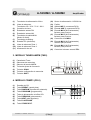
3. MÓDULO TUNER AM/FM (TM-3)
(1) Pantalla del Tuner.
(2) Selectores de memorias.
(3) Selector de banda AM/FM.
(4) Teclas de ajuste de frecuencia.
(5) Tecla de SCAN.
(6) Tecla de confirmación de memorias.
(7) Tecla de SHIFT.
4. MÓDULO CD/MP3 (CD-5)
(1) Pantalla del CD.
(2) Tecla REPEAT (repetir pista).
(3) Tecla RANDOM (reproducción aleatoria).
(4) Tecla PROGRAM (programación).
(5) Tecla de alimentación on/off del CD.
(6) Tecla PREVIOUS (pista anterior).
(7) Tecla NEXT (pista siguiente).
(8) Tecla PLAY/PAUSE.
(9) Tecla STOP/EJECT.
(12) Sector de alimentación 115/230 Vca.
(13) Fusible.
(14) Salida LINE (2 conectores RCA).
(15) Entrada AUX (2 conectores RCA).
(16) Entrada MIC4 (XLR balanceado).
Selector para phantom.
(17) Entrada MIC3 (XLR balanceado).
Selector para phantom.
(18) Control de nivel MOH.
(19) Entrada MIC2 (XLR balanceado).
Selector para phantom.
(20) Entrada MIC1 (XLR balanceado).
Selector para phantom.
(21) Control del volumen entrada TEL.
7654321

A-5230M2 / A-5260M2 Versión 1.1 Página 3 de 9
Amplificador
A
-5230M2 / A-5260M2
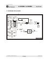
5. DIAGRAMA DE BLOQUES
6
3
3
2
1
3
2
1
3
2
1
3
2
1
AM
FM
M.C.U
LCD
KEY PAD
Serv0
Drive
M.C.U
LCD
KEY PAD
VOX
PHANTOM
POWER
Priority
Priority
CHIME
TONE MASTER
Priority
VOX
VU
100V
70V
25V
8ohm
G
ZONE1 ZONE2
POWER
SWITCH
115V/230V
DC24V
+B
600ohm
1v
8ohm /1W
TO M.O.H
Revision
Sheet of
Drawn By:File: PA5000RD
Size
C
Date : 5-Jun-2002
Titl e

A-5230M2 / A-5260M2 Versión 1.1 Página 4 de 9
Amplificador
A
-5230M2 / A-5260M2
6. CONEXIONES
6.1. CONEXIÓN DE ALIMENTACIÓN
El transformador de alimentación está preparado para 115 Vca o 230 Vca, seleccionables desde
el conmutador de la parte posterior del aparato. Por defecto está configurado en 230 Vca.
6.2. CONEXIÓN BATERÍA (24 VCC)
Cuando se utiliza una batería externa, conectar el terminal de tierra del amplificador. La
estabilidad eléctrica del sistema se incrementará considerablemente al conectar el chasis a tierra.
NOTA: Al hacer la conexión, asegurarse que la polaridad es la correcta. Además, intercalar un
fusible de 15 A.
6.3. CONEXIÓN DE LOS MICRÓFONOS
La entrada de MIC1 es una entrada balanceada que utiliza un conector hembra jack estándar de
6,3 mm de 3 polos (en el panel frontal) o XLR (en el panel posterior).
Las conexiones son las siguientes:
Conector XLR
Pin 1: GND
Pin 2: Señal + (audio)
Pin 3: Señal – (audio)
Conector Jack Stereo 6,3 mm
Blindaje: GND
Punta: Señal + (audio)
Anillo: Señal – (audio)
La entrada MIC1 incorpora un circuito de prioridad VOX que atenúa las entradas MIC2, MIC3,
MIC4 y AUX, pero no la entrada TEL (telefónica).
Las entradas MIC2, MIC3 y MIC4 utilizan conectores XLR y disponen de un selector interno de
alimentación phantom. La alimentación phantom vendrá por defecto desactivada, y se podrá
habilitar de la siguiente forma:
21
3

A-5230M2 / A-5260M2 Versión 1.1 Página 5 de 9
Amplificador
A
-5230M2 / A-5260M2
1. Desconectar el cable de alimentación del aparato.
2. Quitar la tapa.
3. Localizar los puentes 1, 2, 3 y 4 ubicados en el circuito PCB junto a los conectores XLR
de las entradas.
4. Conectar el puente negro al pin central (en posición ON) para habilitar la alimentación
phantom.
6.4. GONG
Haga un puente entre los terminales Mute y G (masa) para activar la función de Gong (Ding-Dong
previo a las llamadas). Mientras esté activada ésta función se atenuarán las señales auxiliares. El
volumen del Gong está configurado de fábrica y es el adecuado para la mayoría de aplicaciones.
6.5. CONEXIÓN TELEFÓNICA (TEL)
La entrada TEL está prevista para avisos de emergencia y no se ve afectada por el control de
volumen Master. El control de volumen es independiente y se encuentra en la parte posterior del
aparato. Dispone de prioridad por VOX y es la más prioritaria de todas las entradas (cortará a las
demás).
6.6. CONEXIÓN DE SALIDA MOH (MUSIC ON HOLD)
El aparato dispone de 2 salidas MOH por las que saldrán las señales de las entradas auxiliares.
Las salidas tienen un control de volumen independiente y no están afectadas por el volumen
Master.
(1) 600 Ω / 1 V para conectar el sistema EPABX, con nivel de salida ajustable.
(2) 8 Ω / 1 W para monitorización.
6.7. CONEXIÓN A OTRAS FUENTES DE SEÑAL (AUX)
El equipo dispone de una entrada auxiliar que permite la conexión de otras fuentes musicales
externas como radios, lectores de CD o reproductores de cassette. El volumen se controlará
desde la parte frontal del equipo (Control de volumen LINE). El selector de fuente de señal con las
opciones Tuner, CD/Cassette, AUX o OFF se encuentra en la parte frontal del aparato.
Los conectores de entrada de AUX son RCA estándar. Los conectores están unidos internamente,
esto permite utilizar una fuente musical estéreo sin necesidad de pasar el señal a mono. En todo
caso, consulte con el fabricante de su fuente musical para asegurarse de que no se producirán
daños en el equipo al conectar los canales derecho e izquierdo en paralelo.
Conector RCA (Phono)
Blindaje: GND
Pin: Señal + (audio)

A-5230M2 / A-5260M2 Versión 1.1 Página 6 de 9
Amplificador
A
-5230M2 / A-5260M2
6.8. CONEXIÓN A LAS SALIDAS BOOSTER
Este equipo dispone de dos salidas de Booster las cuales se podrán utilizar para conectar otro
amplificador si es necesario. La conexión se realizará a través de conectores RCA.
6.9. CONEXIÓN A LOS ALTAVOCES
Este equipo dispone de 4 salidas para conexión de altavoces. Las salidas son de 100 V, 70 V, 25
V y baja impedancia (8 ). NO se podrá utilizar más de una de las salidas a la vez, cualquier
intento de utilizar más de una a la vez, dañará el amplificador.
6.9.1. Línea de 100V
Es la tensión de línea más común en sistemas de megafonía. Cuando el amplificador está a
máxima potencia se dispone de 100 V RMS en los terminales de salida. Utilizar con esta salida
exclusivamente altavoces de línea de 100 V.
Todos los altavoces deben ser cableados en paralelo y la suma de las potencias de cada altavoz
no debe exceder la potencia nominal del amplificador. No es aconsejable cargar el amplificador a
más del 70 % de su salida nominal si éste se utiliza para difusión de música a alto volumen.
Zonas 1 y 2
Además de la salida normal de 100 V, hay dos salidas más de 100 V para dos zonas, las
cuales se podrán seleccionar a través de las teclas de la parte frontal del aparato.
6.9.2. Líneas de 70 V y 25 V
Este sistema es muy común en U.S.A. Se trabaja exactamente de la misma manera que con la
línea de 100 V, salvo que la salida del amplificador será de 70 ó 25 V RMS en los terminales de
salida.
6.9.3. Baja impedancia (8 Ω)
Esta salida permite la conexión de altavoces estándar de baja impedancia. La impedancia de
carga mínima debe ser de 8 Ω. Cuando se utilizan 2 o más altavoces, hay que asegurarse de que
estén conectados de manera que la impedancia de carga se sitúe entre 8 y 16 Ω.

A-5230M2 / A-5260M2 Versión 1.1 Página 7 de 9
Amplificador
A
-5230M2 / A-5260M2
7. FUNCIONAMIENTO DEL REPRODUCTOR DE CD
1. Seleccione modo CD en el conmutador LINE.
2. Presione la tecla POWER en el reproductor de CD.
3. Inserte el disco (etiqueta arriba) en el cajetín y la reproducción se iniciará de manera
automática.
4. Presionando la tecla PAUSE el símbolo ll aparecerá en el display y la reproducción se
detendrá. Presionando PAUSE otra vez la reproducción continuará.
5. Presionando la tecla
se saltará al siguiente pasaje, presionando la tecla
se saltará al
anterior.
6. Presionando la tecla RANDOM, aparecerá RANDOM en la pantalla y los pasajes serán
reproducidos en una secuencia aleatoria.
7. Presionando la tecla REPEAT una vez, el símbolo
aparecerá en el display y el pasaje
en reproducción será repetido.
Cuando la tecla es presionada dos veces el símbolo
aparecerá y se repetirá la
reproducción del disco entero.
Para cancelar estas funciones presione la tecla REPEAT de nuevo.
8. Programación del reproductor de CD (en modo STOP).
a. Pulsar la tecla PROGRAM.
b. Utilizar las teclas de avance
y retroceso para seleccionar el pasaje deseado.
c. Presione la tecla REPEAT para añadir el número del pasaje deseado al programa.
Repetir los pasos (b) y (c) para programar todos los pasajes deseados hasta un
máximo de 20.
d. Pulse la tecla PLAY para iniciar el programa. (El programa se irá repitiendo hasta que
se detenga el equipo)
8. FUNCIONAMIENTO DEL TUNER
Para la recepción de FM, conectar en el conector de entrada de antena una antena dipolo
utilizando un cable coaxial de 75 Ω.
Conectar la antena suministrada con el equipo a los terminales de AM.
1. Seleccionar el modo TUNER con el selector de fuente musical del amplificador.
2. Seleccionar la banda de frecuencias AM o FM.
3. Utilizar los botones UP/DOWN para seleccionar la frecuencia manualmente o bien la tecla de
SCAN para sintonizar las emisoras automáticamente.
4. Para programar/memorizar la emisora seleccionada, pulsar la tecla “ME” de confirmación de
memoria.
5. Pulsar las teclas del M1 al M5 para memorizar los canales del 1 al 5 o bien la tecla SHIFT con
las teclas de M6 al M10 para memorizar los canales del 6 al 10.

A-5230M2 / A-5260M2 Versión 1.1 Página 8 de 9
Amplificador
A-5230M2 / A-5260M2
9. ESPECIFICACIONES TÉCNICAS
9.1. AMPLIFICADOR CON FUENTES MUSICALES (A-5230M2 / A-5260M2)
Modelo A-5230M2 A-5260M2
Alimentación
Red: 115 / 230 Vca ,50 / 60 Hz ± 10 %, Conmutable
Batería: 24 Vcc (+/- 10 %)
Potencia salida máxima
45 W 90 W
Potencia salida nominal (RMS)
30 W 60 W
Salidas
Salida de altavoces: 8 Ω, 25 V, 70 V, 100 V
Salida MOH : 8 Ω 1 W / 600 Ω, 1 V balanceada
Salida de línea: 600 Ω,1 V
Entradas
MIC1: 600 Ω, 1 mV, balanceada con opción phantom (Jump 1)
MIC2: 600 Ω, 1 mV, balanceada con opción phantom (Jump 2)
MIC3: 600 Ω, 1 mV, balanceada con opción phantom (Jump 3)
MIC4: 600 Ω, 1 mV, balanceada con opción phantom (Jump 4)
AUX: 47 kΩ, 200 mV, no balanceada
TEL: 0,1~1 V, 600 Ω, ajustable, balanceada
Respuesta en frecuencia
60 a 15 kHz (+/- 3 dB)
Distorsión harmónica
Inferior al 1 % a 1 kHz,
Relación S/N
Todos los controles de volumen al mínimo: -75 dB
MIC1 a MIC4: -60 dB
AUX : -70 dB
TEL : -70 dB
Controles de tono
Graves: ±10 dB a 100 Hz
Agudos: ±10 dB a 10 kHz
Controles
MIC1 a MIC4: control de volumen
LINE (AUX/Tuner/CD): control de volumen
MASTER: control de volumen
TEL: control de volumen
MOH: control de nivel de salida
Controles de tono: BASS/TREBLE
ZONE 1 / ZONE 2: Teclas de selección de zona
AC 115 V / 230 V Selector de tensión de alimentación.
Indicadores
Led de POWER (LED), Vumeter de nivel de Salida (3 LEDS)
Consumo CA
100 W 200 W
Consumo CC
2 A 4 A
Gong
Gong de 2 notas (Señal de Ding-Dong previo a un aviso)
Prioridad
Nivel de prioridad
(Usando para los MIC1~5, el conector XLR o el conector jack)
TEL / Emergencia: Prioridad 1 (máxima)
MIC1: Prioridad 2
MIC2, MIC3, MIC4. Aux / Tuner/ CD-Tape: Prioridad 3 (mínima)
Dimensiones
88 × 430 × 300 mm
Peso
7 kg 8,5 kg
Color
Negro
Opciones de montaje
Sobremesa o en rack de 19”

A-5230M2 / A-5260M2 Versión 1.1 Página 9 de 9
Amplificador
A
-5230M2 / A-5260M2
9.2. UNIDAD REPRODUCTORA DE CD/MP-3 (CD-5)
Modelo CD-5
Distorsión
< 0.1 %
Relación S/N
> 80 dB
Salida
850 mV
Funciones
EJECT/STOP, PAUSE/PLAY, tecla NEXT, tecla
PREVIOUS, POWER, PROGRAM, RANDOM, REPEAT
9.3. UNIDAD DE TUNER DIGITAL AM / FM (TM-3)
Modelo TM-3
Rango de frecuencias
FM: 87,5 ~ 108 MHz
AM: 522 ~ 1.620 kHz
Sensibilidad
FM: 2 µV (26 dB S/N)
AM: 30 µV (30 dB S/N)
Respuesta en frecuencia
30 Hz ~ 15 kHz (+1 / -3 dB)
Distorsión
< 1 %
Relación S/N
> 63 dB (1 mV, FM)

A-5230M2 / A-5260M2 Version 1.1
A-5230M2 / A-5260M2
Amplifier
SAFETY INSTRUCTIONS:
IMPORTANT
The wires in the mains lead are colored
in accordance with the following code:
GENERAL INSTALLATION
¾ DO NOT run microphone cables near mains, data, telephone or 100 V line cables.
¾ DO NOT run 100 V line cables near data, telephone or other low voltage cables.
¾ DO NOT exceed 90 % of the amplifiers output power when using 100 V line (speech only).
¾ DO NOT exceed 70 % of the amplifiers output power when using 100 V line (high level
background music).
¾ DO NOT use re-entrant horn loudspeakers for background music unless the loudspeaker has
been specifically designed for this purpose.
¾ AVOID jointing the Microphone cable, when this is unavoidable make sure a good screened
connector is used, e.g. XLR.
¾ ALWAYS use a balanced or floating low impedance microphone terminating into a balanced
input on long microphone cable runs.
¾ ALWAYS use a mains grade double insulated cable for the loudspeaker cable runs.
¾ ENSURE that all loudspeakers are in-phase.
¾ ENSURE that there are no short circuits on the loudspeaker line before connecting to the
amplifier.
Green & yellow Earth (E)
Blue Neutral (N)
Brown Live (L)
As the colours of the wires in the mains lead of this
apparatus do not correspond with the colored
markings identifying the terminals in your plug
proceed as follows:
The wire, which is colored green and yellow, must
be connected to the terminal, which is marked by
the letter E, or by the safety earth symbol or colored
green and yellow. The wire, which is colored blue,
must be connected to the terminal, which is marked
with the letter N or colored black. The wire, which is
colored brown, must be connected to the terminal,
which is marked with the letter L or colored red.
If a 13 A (B.S.1363) plug or any other type of plug is
used, a 5 A fuse must be fitted either in the plug or
at the distribution board.

A-5230M2 / A-5260M2 Version 1.1
A-5230M2 / A-5260M2
Amplifier
1. FRONT PANEL............................................................................................................ 1
2. REAR PANEL.............................................................................................................. 1
3. FM/AM TUNER UNIT (TM-3)....................................................................................... 2
4. CD/MP3 PLAYER UNIT (CD-5) ................................................................................... 2
5. BLOCK DIAGRAM ...................................................................................................... 3
6. CONNECTIONS........................................................................................................... 4
6.1. MAINS CONNECTION ......................................................................................................4
6.2. BATTERY CONNECTION (24 VDC).................................................................................4
6.3. MICROPHONE CONNECTIONS.......................................................................................4
6.4. CHIME ...............................................................................................................................5
6.5. TELEPHONE CONNECTION (TEL)..................................................................................5
6.6. MOH (Music On Hold) OUTPUT CONNECTION .............................................................5
6.7. AUX (Line) CONNECTION ...............................................................................................5
6.8. BOOSTER LINE OUTPUT CONNECTION .......................................................................6
6.9. LOUDSPEAKER CONNECTION ......................................................................................6
6.9.1. 100 V Line................................................................................................................................6
6.9.2. 70 V & 25 V Line......................................................................................................................6
6.9.3. Low impedance (8 Ω) .............................................................................................................6
7. CD/MP3 PLAYER OPERATION.................................................................................. 7
8. TUNER OPERATION................................................................................................... 7
9. TECHNICAL SPECIFICATIONS ................................................................................. 8
9.1. POWER AMPLIFIER WITH MUSIC SOURCES (A-5230M2 / A-5260M2)........................8
9.2. CD/MP3 PLAYER UNIT (CD-5).........................................................................................9
9.3. AM/FM DIGITAL TUNER (TM-3).......................................................................................9

A-5230M2 / A-5260M2 Version 1.1 Page 1 of 9
A-5230M2 / A-5260M2
Amplifier
1. FRONT PANEL
PUBLIC ADDRESS AMPLIFIER WITH MUSCI SOURCE
0 dB
- 6
- 20
ZONE 2ZONE 1
12 3 4 5 6 7 8 9 10 11
232221201918171615141312
(1) MIC1 input (6.3mm phone jack/balanced).
(2) MIC1 volume control.
(3) MIC2 volume control.
(4) MIC3 volume control.
(5) MIC4 volume control.
(6) Music Source Select
(AUX / TUNER / CD-TAPE / OFF).
(7) LINE (Music Source) volume control.
(8) Master tone control (BASS).
(9) Master tone control (TREBLE).
(10) Master volume control (all inputs except TEL).
(11) Power ON/OFF switch.
(12) VU meter (LEDs for -20, -6, 0 dB).
2. REAR PANEL
+24V 0 COM 8 25V 70V 100V
Ω
DC INPUT
115V~ 230V~
COM 100V COM 100V
ZONE 1 ZONE 2
FM AM
ANT
LINE
OUT
AUX
L
R
600 1V 8 1W MUTE G COM HOTΩΩ
MOH
OUTPUT LEVEL
TEL
INPUT LEVEL
MIC 1MIC 2MIC 3MIC 4
BALANCED
(13) Tuner display.
(14) Memory keys.
(15) AM/FM selection key.
(16) Frequency UP/DOWN key.
(17) SCAN key.
(18) SET memory key.
(19) SHIFT key.
(20) CD player unit built in slot.
(21) ZONE 1 select switch button.
(22) Power on indicator LED.
(23) ZONE 2 select switch button.

A-5230M2 / A-5260M2 Version 1.1 Page 2 of 9
A-5230M2 / A-5260M2
Amplifier
(1) 24 V dc power supply terminals.
(2) Loudspeaker output terminals
(8 Ω / 25 V / 70 V / 100 V).
(3) Earth connection screw.
(4) FM antenna input.
(5) AM antenna input.
(6) MOH (music on hold ) output
terminals.
(7) Manual Muting terminals.
(8) TEL input terminals.
(9) Zone 1 loudspeaker output terminals.
(10) Zone 2 loudspeaker output terminals.
(11) Mains input socket.
(12) Mains voltage 115 V / 230 V switch.
(13) AC fuse holder.
(14) Line output (2 × RCA phono).
3. FM/AM TUNER UNIT (TM-3)
(1) Tuner display.
(2) Memory keys.
(3) AM/FM selection key.
(4) Frequency up/down key.
(5) SCAN key.
(6) Set memory key.
(7) SHIFT key.
4. CD/MP3 PLAYER UNIT (CD-5)
(1) CD display.
(2) REPEAT key.
(3) RANDOM key
(4) PROGRAM key.
(5) CD power on/off key.
(6) PREVIOUS key.
(7) NEXT key.
(8) PLAY/PAUSE key.
(9) STOP/EJECT key.
(15) Auxiliary input (2 × RCA phono ).
(16) MIC4 input (XLR / balanced with selectable
phantom power).
(17) MIC3 input (XLR / balanced with selectable
phantom power).
(18) MOH output level control
(19) MIC2 input (XLR / balanced with selectable
phantom power).
(20) TEL input level control
(21) MIC1 input (XLR / balanced with selectable
phantom power).
7654321

A-5230M2 / A-5260M2 Version 1.1 Page 3 of 9
A-5230M2 / A-5260M2
Amplifier
5. BLOCK DIAGRAM
6
3
3
2
1
3
2
1
3
2
1
3
2
1
AM
FM
M.C.U
LCD
KEY PAD
Serv0
Drive
M.C.U
LCD
KEY PAD
VOX
PHANTOM
POWER
Priority
Priority
CHIME
TONE MASTER
Priority
VOX
VU
100V
70V
25V
8ohm
G
ZONE1 ZONE2
POWER
SWITCH
115V/230V
DC24V
+B
600ohm
1v
8ohm /1W
TO M.O.H
Revision
Sheet of
Drawn By:File: PA5000RD
Size
C
Date : 5-Jun-2002
Titl e

A-5230M2 / A-5260M2 Version 1.1 Page 4 of 9
A-5230M2 / A-5260M2
Amplifier
6. CONNECTIONS
6.1. MAINS CONNECTION
The supply transformer has been designed for use either 115 Vac or 230 Vac, selected by slide
switch on rear panel. The amplifier is factory set at 230 Vac mains Voltage.
6.2. BATTERY CONNECTION (24 VDC)
When using external batteries, earth the amplifier via the screw terminal because of the high
voltages present. Electrical stability of the system is increased by earthing the case.
NOTE: The connection cable must be fitted with an in-line fuse, quick blow type F15A. When
connecting batteries please ensure correct polarity.
6.3. MICROPHONE CONNECTIONS
MIC1 input is either a balanced standard 1/4” stereo jack on front panel or XLR on the rear panel
(With selectable Phantom power).
Wiring is as follows:
XLR connector
Pin 1: GND
Pin 2: Signal + (audio)
Pin 3: Signal – (audio)
Jack Stereo 6,3 mm connector
Sleeve: GND
Tip: Signal + (audio)
Ring: Signal– (audio)
MIC1 input has VOX priority which will override MIC2 ~ 4 and AUX (Line) input signals but NOT
the TELEPHONE input.
MIC2 ~ 4 inputs are XLR with selectable Phantom power located on the rear panel and wired as
above. The Phantom power is factory set to off and can be enabled as follows:
21
3

A-5230M2 / A-5260M2 Version 1.1 Page 5 of 9
A-5230M2 / A-5260M2
Amplifier
Remove power lead from the AC wall socket.
Remove top cover.
Locate the link pins (Marked jump 1, 2, 3 & 4) on the PCB behind each microphone XLR input
socket.
Connect the black shorting plug to the central pin and ON position to enable the Phantom
power.
6.4. CHIME
Wire between Mute and G (ground) terminals to activate the chime function (“Ding-Dong”
attention signal preceding a call). While this function is activated auxiliary inputs are attenuated.
The default chime volume is pre-set at the factory and is adequate for most applications.
6.5. TELEPHONE CONNECTION (TEL)
(TEL) input is for emergency announcements/signals and is not affected by the master volume
control. Input level can be set by rotary control on the rear panel. The TEL input has the highest
priority and will override all other inputs.
6.6. MOH (Music On Hold) OUTPUT CONNECTION
Two MOH outputs are provided with independent volume control and they aren’t affected by the
master volume control. They are used to output only auxiliary signals.
600 Ω / 1 V to feed an EPABX system. Output level adjustable. Please consult your EPABX
handbook to use this facility.
8 Ω, 1 W for monitoring applications.
6.7. AUX (Line) CONNECTION
The equipment provides an auxiliary input that may be used for connecting other signal sources
such as a Radio Tuner, CD or Cassette player. LINE level Control is shared with the built-in Tuner
and CD. A rotary switch is located on the front panel for selection of Tuner, CD/Cassette, Aux and
OFF. The LINE level control operates on each of the input sources. To operate select the desired
music source using the rotary switch and turn the LINE control clockwise to increase the volume or
anticlockwise to reduce the volume.
The AUX input sockets are standard RCA phono, two sockets are supplied and these are linked
together internally, this allows stereo signal source to be used without the need to obtain a special
lead, however you may wish to check with the manufacturer of the signal source to ensure that no
damage will result if the left and right output channels are put in parallel.

A-5230M2 / A-5260M2 Version 1.1 Page 6 of 9
A-5230M2 / A-5260M2
Amplifier
RCA connector (Phono)
Sleeve: GND
Pin: Signal + (audio)
6.8. BOOSTER LINE OUTPUT CONNECTION
This equipment provides two booster output sockets which can be used to drive a booster amplifier
in situations where more power is required. Connection is via RCA phone plug. (See above)
6.9. LOUDSPEAKER CONNECTION
This equipment provides four different types of loudspeaker output, these are 100 V, 70 V, 25 V
line and low impedance, you can only use one of these output at any one time, any attempt to use
two or more of these may result in damage to the amplifier.
6.9.1. 100 V Line
These loudspeakers are most commonly used in the Europe for PA distribution. When the amplifier
is at full output, 100V RMS will be present at the output terminals. Only use 100 V line
loudspeakers with this output. All loudspeakers are wired in parallel and the sum of the power
tapping of each loudspeaker must not exceed the rated output of the amplifier, ideally, due to the
nature of loudspeaker and transformer impedance’s. It is advisable not to load the amplifier to
greater than 70 % of its rated output when using music sources.
1 & 2 Zones
In addition to the normal 100 V line output there are two sets of 100 V line terminals for 2
zones which can be selected using the push buttons on the front panel
6.9.2. 70 V & 25 V Line
This system is common in the U.S.A., it operates on exactly the same principals as 100 V line
except that at rated output the amplifier will have 70 V RMS or 25 V RMS on its output terminals.
6.9.3. Low impedance (8 Ω)
This output allows connection of standard low impedance loudspeakers, the minimum load
impedance must be 8 Ω, when two or more loudspeakers are used ensure that they are wired in
such a way that the load impedance is between 8 Ω and 16 Ω.

A-5230M2 / A-5260M2 Version 1.1 Page 7 of 9
A-5230M2 / A-5260M2
Amplifier
7. CD/MP3 PLAYER OPERATION
Select CD mode with LINE select switch.
1. Select CD mode with LINE select switch.
2. 2. Press POWER key on CD player.
3. Load disc (label side up) into player and PLAY starts automatically.
4. Press PAUSE key and symbol ll appears in the display and play is suspended. Press pause
key to resume play.
5. Pressing
key selects the next track and
key the previous track.
6. Press the RANDOM key, random appears in the display and tracks are played out of
sequence.
7. Press the REPEAT key once and symbol
appears on the display and the current track Is
repeated. When the key is pressed twice the symbol
appears and indicates repeat play
of the disc. TO cancel these functions press the REPEAT key.
8. Programming the CD player – in STOP mode.
a. Press the PROGRAM key.
b. Use the next
or previous key to select a track.
c. Press REPEAT key to memorise the selected track in your program. Repeat stages (ii)
and (iii) to program a maximum of 20 tracks.
d. Press the PLAY key to start the program (Note: The program repeats itself until the CD
player is stopped).
8. TUNER OPERATION
For FM reception connect a dipole aerial using 75 Ω coaxial to the socket at the rear of the unit.
Connect the supplied antenna to the AM spring loaded terminals.
1. Select TUNER mode with the Line select switch.
2. Select AM or FM with the BAND key.
3. Use the UP/DOWN keys to set a frequency manually or the SCAN key to automatically search
for the desired station.
4. To program a station press the ME (Memory) key.
5. Press a MEMORY key (M1 to M5) or SHIFT key and memory key (M6 to M10) to store a
frequency.

A-5230M2 / A-5260M2 Version 1.1 Page 8 of 9
A-5230M2 / A-5260M2
Amplifier
9. TECHNICAL SPECIFICATIONS
9.1. POWER AMPLIFIER WITH MUSIC SOURCES (A-5230M2 / A-5260M2)
Model A-5230M2 A-5260M2
Supply mains voltage
AC 115 V / 230 V, 50 / 60 Hz ± 10 %, Switchable
Battery voltage
DC 24 V (max.10 % deviation)
Maximum power
45 W 90 W
Rated power (RMS)
30 W 60 W
Outputs
Speaker outputs: 8 Ω, 25 V, 70 V & 100 V
MOH output: 8 Ω 1 W / 600 Ω, 1 V balanced
Line out: 600 Ω, 1 V
Inputs
MIC1: 600 Ω, 1mV, balanced. Phantom power selectable (Jump 1)
MIC2: 600 Ω, 1mV, balanced. Phantom power selectable (Jump 2)
MIC3: 600 Ω, 1mV, balanced. Phantom power selectable (Jump 3)
MIC4: 600 Ω, 1mV, balanced. Phantom power selectable (Jump 4)
AUX: 47 kΩ, 200 mV, unbalanced.
TEL: 0,1 ~ 1 V, 600 Ω, adjustable, balanced
Frequency response
60 ~ 15 kHz ± 3 dB
Total harmonic distortion
Less than 1% at 1kHz, rated power
Signal to noise ratio
All Volume Controls C.C.W: 75 dB below rated power
MIC1 ~ MIC4: 60 dB below rated power
AUX: 70 dB below rated power
TEL: 70 dB below rated power
Tone controls
Bass : ±10 dB at 100 Hz
Treble: ±10 dB at 10 kHz
Controls
MIC1 ~ MIC4: volume control
Line (Aux/Tuner/CD/Cassette): volume control
MASTER: volume control
TEL: input level control
MOH: output level control
Tone controls: BASS / TREBLE
ZONE1 / ZONE2: push buttons
AC 115 V / 230 V: voltage selector switch
Indicators
Power indicator (LED), output level meter (3 LEDS)
AC power consumption
100 W 200 W
DC power consumption
2 A 4 A
Chime
Two tone chime (Ding-done attention signal preceding a call)
Priority
Priority level (Using for MIC1~5, the XLR connector or phone jack)
TEL / Emergency: Priority 1 (highest)
MIC1: Priority 2
MIC2 - MIC3 - MIC4 - Aux / Tuner/ CD-Tape: Priority 3 (lowest)
Dimentions ( H x W x D )
88 × 430 × 300 mm
Weight
Approx: 7,0 kg Approx: 8,5 kg
Color
Black
Mounting options
Table top or, 19” rack mountable

A-5230M2 / A-5260M2 Version 1.1 Page 9 of 9
A-5230M2 / A-5260M2
Amplifier
9.2. CD/MP3 PLAYER UNIT (CD-5)
Model CD-5
Distortion
< 0,1 %
S/N
> 80 dB
Output
850 mV
Function
EJECT / STOP, PAUSE / PLAY, NEXT key, PREVIOUS
key, POWER, PROGRAM, RANDOM, REPEAT
9.3. AM/FM DIGITAL TUNER (TM-3)
Model TM-3
Tuning range
FM: 87,5 ~ 108 MHz
AM: 522 ~ 1.620 kHz
Sensitivity
FM: 2 µV (26 dB S/N)
AM: 30 µV (30 dB S/N)
Frequency response
30 Hz ~ 15 kHz (+1 / -3 dB)
Distortion
< 1 %
S/N
>63 dB (1 mV, FM )
Output
500 mV (0 ~ 1 V adjustable)
-
 1
1
-
 2
2
-
 3
3
-
 4
4
-
 5
5
-
 6
6
-
 7
7
-
 8
8
-
 9
9
-
 10
10
-
 11
11
-
 12
12
-
 13
13
-
 14
14
-
 15
15
-
 16
16
-
 17
17
-
 18
18
-
 19
19
-
 20
20
-
 21
21
-
 22
22
-
 23
23


Optimus A-5230M2 Manual de usuario
- Categoría
- Reproductores de CD
- Tipo
- Manual de usuario
- Este manual también es adecuado para
En otros idiomas
- English: Optimus A-5230M2 User manual
Documentos relacionados
-
Optimus A-5240Z6 Manual de usuario
-
-
-
-
-
-
-
-
-
Otros documentos
-
 Work Pro PA 60/2 Manual de usuario
-
Work-pro PA 120/2 Manual de usuario
-
-
LD Systems IMA30 Installation Amplifier 35W El manual del propietario
-
LD Systems IMA30 Installation Amplifier 35W El manual del propietario
-
Fonestar MAX-360Z Manual de usuario
-
-
Ecler HMA120 Manual de usuario
-
-
 Work Pro PA 50 Manual de usuario

