
ELECTRONICS FOR SPECIALISTS ELECTRONICS FOR SPECIALISTS ELECTRONICS FOR SPECIALISTS ELECTRONICS FOR SPECIALISTS
BEDIENUNGSANLEITUNG
INSTRUCTION MANUAL
MODE D’EMPLOI
ISTRUZIONI PER L’USO
GEBRUIKSAANWIJZING
MANUAL DE INSTRUCCIONES
INSTRUKCJA OBSŁUGI
SIKKERHEDSOPLYSNINGER
SÄKERHETSFÖRESKRIFTER
TURVALLISUUDESTA
2-Kanal-Empfänger
für Funkmikrofone
2-Channel Receiver
for Wireless Microphones
TXS-920
Bestell-Nr. • Order No. 25.5240
823 – 832 MHz
863 – 865 MHz

2
Deutsch ...........Seite 4
English ............Page 7
Français ...........Page 10
Italiano............Pagina 13
Nederlands ........Pagina 16
Español ...........Página 19
Polski .............Strona 22
Dansk .............Sida 25
Svenska ...........Sidan 25
Suomi.............Sivulta 25
ELECTRONICS FOR SPECIALISTS ELECTRONICS FOR SPECIALISTS ELECTRONICS FOR SPECIALISTS ELECTRONICS FOR SPECIALISTS

3
TXS-920
POWER
SYNC
RECEIVER 1
SET
MIN MAX
VOLUME
SYNC
RECEIVER 2
SET
VOLUME
MIN MAX
ANT B ANT A
CH2
SQ
BALANCED
UNBALANCED
MICLINE
SQ
BALANCED
UNBALANCED
MICLINE
AUDIO OUT
CH1
AUDIO OUT
MIX OUT
0 dB
DC OUT
8V/100mA
DC OUT
8V/100mA
SYNC
RECEIVER 1
SET
MIN MAX
VOLUME
SQ
BALANCED
UNBALANCED
MICLINE
CH1
AUDIO OUT
1 1
2
3 4 5 6
7 7
8 9
10 11 12
MANUAL
SCAN
PRESET
SYNC
CH
GP
P1 P4P2 P3
CH
1 8
FREQ MHz
RF AF
2 3 4 5 6 7
MUTE
D E F G H I
B C
A
➀
➁
➂
➄
➂

4
Deutsch
Deutsch
Deutsch Seite
2-Kanal-Empfänger
für Funkmikrofone
Diese Bedienungsanleitung richtet sich an
Benutzer ohne besondere Fachkenntnisse.
Bitte lesen Sie die Anleitung vor dem Betrieb
gründlich durch und heben Sie sie für ein spä-
teres Nachlesen auf.
Auf der ausklappbaren Seite 3 finden Sie
alle beschriebenen Bedienelemente und An-
schlüsse.
1 Übersicht
Empfangseinheit 1
Empfangseinheit 2
1.1 Front
1 Empfangsantennen
2 Taste POWER zum Ein- und Ausschalten
(für ca. 1 Sek. gedrückt halten)
Empfangseinheit 1*
3
Taste SYNC für die Synchronisation von
Empfangseinheit und Sender: Während
am Sender die Synchronisierungstaste
gedrückt gehalten wird [SYNC (D) blinkt
im Display], die Taste SYNC an der Emp-
fangseinheit kurz drücken, der Sender
ist damit auf den Übertragungskanal der
Empfangseinheit eingestellt.
4 Display (
☞
Abb. 3)
A Anzeige für den Betriebsmodus
„MANUAL“ manuelle Frequenzeinstel-
lung (in 25-kHz-Schritten)
„SCAN“ Kanalsuchlauf
„PRESET“ Auswahl eines Kanals aus
einer von 4 voreingestell-
ten Gruppen (8 Kanäle pro
Gruppe)
Den gewünschten Modus mit der Taste
oder anwählen (Taste ca. 1 Sek.
lang drücken).
B
im Modus PRESET: Anzeige der Gruppe
(„P1“ … „P4“)
C im Modus PRESET: Anzeige der Kanal-
nummer („1“ … „8“) innerhalb der
Gruppe
D Anzeige „SYNC“ für die Synchronisa-
tion von Empfangseinheit und Sender:
☞
Taste SYNC (3)
E Anzeige der Kanalnummer
F Anzeige „MUTE“, signalisiert Stumm-
schaltung der Audioausgänge während
der Einstellungen über die Tasten SET,
und (5) sowie bei Betätigung der
Ein- /Ausschalttaste (2)
G Anzeige der Funkfrequenz
H
Balkenanzeige „RF“ (Radio Frequency)
für die Empfangsstärke des Funk-
signals
I Balkenanzeige „AF“ (Audio Frequency)
für die Lautstärke des empfangenen
Audiosignals
5 Tasten SET, und zum Einstellen des
Übertragungskanals im gewählen Be-
triebsmodus:
☞
Kap. 7
6
Lautstärkeregler für das Ausgangssignal
der Empfangseinheit
1.2 Rückseite
7 Antenneneingänge A und B (BNC-Buch-
sen)
8
Audioausgang für das Mischsignal der
beiden Empfangseinheiten (6,3-mm-Klin-
kenbuchse, asym.) zum An schluss an
einen Line-Eingang z. B. eines Mischpults
oder Verstärkers
9 Stromversorgungsbuchse zum Anschluss
des beiliegenden Netzgerätes
Empfangseinheit 1*
10
Audioausgänge, jeweils zum Anschluss
an einen Mikrofoneingang oder einen
Line-Eingang z. B. eines Mischpults oder
Verstärkers
– XLR-Einbaustecker, symmetrisch
– 6,3-mm-Klinkenbuchse, asymmetrisch
11 Pegelumschalter für die Audioausgänge
(10), zur Anpassung des Ausgangspegels
an den Eingang des angeschlossenen
Audiogeräts
MIC bei Anschluss an einen Mikrofonein-
gang
LINE bei Anschluss an einen Line-Ein-
gang
12
Regler zum Einstellen des Schwellwerts
für die Rauschsperre (Squelch)
2 Sicherheitshinweise
Die Geräte (Empfänger und Netzgerät) ent-
sprechen allen relevanten Richtlinien der EU
und tragen deshalb das -Zeichen.
WARNUNG
Das Netzgerät wird mit lebens-
gefährlicher Netzspannung
versorgt. Nehmen Sie deshalb
niemals selbst Eingriffe daran
vor. Es besteht die Gefahr
eines elektrischen Schlages.
•
Die Geräte sind nur zur Verwendung im
Innenbereich geeignet. Schützen Sie sie
vor Tropf- und Spritzwasser, hoher Luft-
feuchtigkeit und Hitze (zulässiger Ein-
satztemperaturbereich 0 – 40 °C).
•
Ziehen Sie sofort das Netzgerät aus der
Steckdose,
1. wenn sichtbare Schäden am Empfänger
oder am Netzgerät vorhanden sind,
2.
wenn nach einem Sturz oder Ähnlichem
der Verdacht auf einen Defekt besteht,
3. wenn Funktionsstörungen auftreten.
Geben Sie die Geräte in jedem Fall zur Re-
paratur in eine Fachwerkstatt.
•
Verwenden Sie zum Reinigen nur ein tro-
ckenes, weiches Tuch, niemals Wasser oder
Chemikalien.
•
Werden die Geräte zweckentfremdet, nicht
richtig angeschlossen, falsch bedient oder
nicht fachgerecht repariert, kann keine Haf-
tung für daraus resultierende Sach- oder
Personenschäden und keine Garantie für
die Geräte übernommen werden.
Sollen die Geräte endgültig aus dem
Betrieb genommen werden, über-
geben Sie sie zur umweltgerechten
Entsorgung einem örtlichen Recy-
clingbetrieb.
3 Einsatzmöglichkeiten
Mit diesem 2-Kanal-Multifrequenz-Empfän-
ger TXS-920 und zwei Sendern der TXS-900-
Serie von IMG STAGELINE (Funkmikrofon
TXS-900HT oder Taschensender TXS-900HSE
mit angeschlossenem Mikrofon) lassen sich
zwei drahtlose Audio-Übertragungssysteme
aufbauen, z. B. für Bühneneinsätze. Der
Empfänger verwendet True-Diversity-Tech-
nik und arbeitet in den zwei UHF-Bereichen
823 – 832 MHz und 863 – 865 MHz.
Die zwei identisch ausgelegten Emp-
fangseinheiten des Geräts werden getrennt
bedient. Der Übertragungskanal lässt sich
für jede Empfangseinheit manuell oder über
einen Suchlauf einstellen oder aus einer
von 4 voreingestellten Gruppen auswählen
(8Kanäle pro Gruppe). Die Synchronisation
von Empfangseinheit und Sender erfolgt
per Funkübertragung: Wird am Sender die
Syn chronisierungstaste gedrückt ge halten
und gleichzeitig die Taste SYNC an der Emp-
fangseinheit kurz gedrückt, stellt sich der
Sender auf den Übertragungskanal der Emp-
fangseinheit ein.
3.1 Konformität und Zulassung
Hiermit erklärt MONACOR INTERNATIONAL,
dass der Empfänger TXS-920 der Richtlinie
2014 / 53 / EU entspricht. Die EU-Konformitäts-
erklärung ist im Internet verfügbar:
www.img-stageline.de
Frequenzbereich 863 – 865 MHz:
Anmelde-und gebührenfrei in den EU- und
EFTA-Staaten.
Frequenzbereich 823 – 832 MHz:
Es bestehen Beschränkungen oder Anfor-
derungen in folgenden Ländern:
AT CZ FR LT PL
SE UK
4 Aufstellung / Rackmontage
Der Empfänger kann als Tischgerät verwendet
oder in ein Rack (482 mm / 19”) eingebaut
werden. Für den Rackeinbau die beiden bei-
liegenden Rackwinkel mit jeweils 3 Schrau-
ben an der linken und der rechten Seite des
Empfängers befestigen.
Für optimalen Empfang sollten die Sen-
der und der Empfänger Sichtverbindung
haben und nicht in unmittelbarer Nähe zu
großen Metallflächen oder digitalen Geräten
(wie z. B. CD-Spieler, Computer) positioniert
werden.
* Die Bedientasten und Anschlüsse von Empfangseinheit 2 sind identisch.

5
Deutsch
5 Antennen und Audiogerät
anschließen
5.1 Antennen
Die mitgelieferten Empfangsantennen (1) auf
die Antennenbuchsen (7) stecken und senk-
recht stellen.
Bei einem Rackeinbau des Geräts kann es
für einen besseren Empfang günstiger sein,
die Empfangsantennen an der Frontseite des
Racks zu platzieren. Zu diesem Zweck besit-
zen die mitgelieferten Rackwinkel jeweils ein
Loch für die Antennenmontage. Um eine
Antenne an einem Rackwinkel anzubringen:
1)
Einen BNC-Adapter (2 × BNC-Buch se,
50 Ω) durch das dafür vorgesehe ne Loch
des Winkels stecken und festschrauben.
2) Auf die vordere Buchse des Adapters die
An tenne stecken.
3) Die hintere Buchse des Adapters über ein
50-Ω-BNC-Kabel mit einer der Antennen-
buchsen auf der Geräterückseite verbin-
den.
5.2 Audioanschlüsse
Um dem nachfolgenden Audiogerät (z. B.
Misch pult, Verstärker) die Signale der bei-
den Empfangseinheiten getrennt zuzu-
führen, sind pro Empfangseinheit zwei Aus-
gänge (10) verfügbar. Jede Empfangseinheit
über einen ihrer beiden Ausgänge an einen
Mikrofoneingang oder an einen Line-Eingang
des nachfolgenden Geräts an schließen:
– symmetrisch beschalteter XLR-Ausgang.
Bei großer Distanz zwischen den Geräten
sollte dieser Ausgang bevorzugt werden.
Die symmetrische Signalführung bietet
einen besseren Schutz gegen Störeinstrah-
lungen, die besonders bei längeren Kabeln
auftreten kön nen.
– asymmetrisch be schalteter 6,3-mm-Klin-
kenausgang (ein passendes Anschlusskabel
liegt bei)
Hinweis: Verwenden Sie den symmetrischen Aus-
gang und den asymmetrischen Ausgang nicht
gleichzeitig, da dies die Signalqualität beeinträch-
tigen kann.
Mit dem Schiebeschalter (11) den Ausgangs-
pegel an den Eingang anpassen: bei An-
schluss an einen Line-Eingang den Schalter
in die linke Position LINE stellen, bei Anschluss
an einen Mikrofoneingang den Schalter in die
rechte Position MIC.
Soll dem nachfolgenden Audiogerät das
Mischsignal der beiden Empfangsein-
heiten zugeführt werden, den asymmetrisch
be schalteten 6,3-mm-Klinkenausgang MIX
OUT (8) an einen Line-Eingang des Audio-
geräts anschließen.
6 Inbetriebnahme
Das beiliegende Netzgerät an die Stromver-
sorgungsbuchse (9) anschließen und in eine
Netzsteckdose (230 V / 50 Hz) stecken. Bei Ver-
bindung mit der Stromversorgung schaltet
sich der Empfänger ein.
Mit der Taste POWER (2) lässt sich der Emp-
fänger ein- und ausschalten: Die Taste für ca.
1 Sek. gedrückt halten.
Wird der Empfänger längere Zeit nicht
be nutzt, sein Netzgerät aus der Steckdose
ziehen, denn es verbraucht auch bei ausge-
schaltetem Empfänger einen geringen Strom.
7 Übertragungskanal
einstellen
Für die zwei Funksysteme, die sich mit die-
sem 2-Kanal-Empfänger aufbauen lassen,
die Übertragungskanäle getrennt an jeder
Empfangseinheit einstellen. Die Einstellung
erfolgt über die Tasten SET, und (5) der
Empfangseinheit. Es stehen 3 Betriebsmodi
zur Verfügung.
Während der Kanaleinstellung einer Emp-
fangseinheit sollten eingeschaltete Sender
gleichzeitig betriebener Funksysteme sich
nicht zu nah am Empfänger befinden (Ab-
stand min. 1 m).
7.1 Betriebsmodus wählen
Das Display zeigt den aktuell eingestellten
Modus an: „MANUAL“, „SCAN“ oder „PRE-
SET“ (A). Den ge wünschten Modus mit der
Taste
oder
an wählen: Die Taste ca. 1 Sek.
lang drücken, um auf den jeweils nächsten
Modus zu wechseln (oder sie gedrückt halten,
bis der Modus angezeigt wird, dann lösen).
7.2 Modus MANUAL
Im Modus MANUAL lässt sich aus den
442Funkfrequenzen die ge wünschte ma nuell
einstellen (
☞
Tabelle ➊, Seite 6).
1) Mit der Taste oder den Modus MA-
NUAL anwählen (
☞
Kap. 7.1). Das Display
zeigt die zuletzt im Modus MANUAL oder
SCAN eingestellte Funkfrequenz (G) und
die entsprechende Kanalnummer (E) an.
2)
Um den Einstellmodus zu aktivieren, die
Taste SET für ca. 1 Sek. gedrückt halten,
bis die Kanalanzeige (E) und die Frequenz-
anzeige (G) blinken.
Hinweis: Nach einigen Sekunden ohne Betäti-
gung einer Tas te wird der Einstellmodus wieder
verlassen.
3) Mit der Taste oder die Frequenz ein-
stellen (in 25-kHz-Schritten). Zum Durch-
laufen der Frequenzen kann die jeweilige
Taste auch gedrückt gehalten werden.
4)
Der Einstellmodus wird automatisch einige
Sekunden nach dem letzten Tastendruck
verlassen, kann aber auch durch Drücken
der Taste SET beendet werden.
7.3 Modus SCAN
Im Modus SCAN sucht die Empfangseinheit
automatisch den nächsten freien Kanal. Bei
gleichzeitigem Betrieb mehrerer Systeme
die Sender, die bereits auf einen Über-
tragungskanal eingestellt wurden, vor dem
Durchführen des Suchlaufs einschalten. So
werden die Kanäle, die schon belegt oder
inkompatibel mit den bereits eingestellten
sind, beim Suchlauf übersprungen. In diesem
Modus lassen sich, abhängig von den örtli-
chen Bedingungen, max. 12 Kanäle gleichzei-
tig betreiben, ohne sich gegen seitig zu stören.
1) Mit der Taste oder den Modus SCAN
anwählen (
☞
Kap. 7.1). Das Display zeigt
die zuletzt im Modus MANUAL oder SCAN
eingestellte Funkfrequenz (G) und die ent-
sprechende Kanalnummer (E) an.
2)
Um den Einstellmodus zu aktivieren, die
Taste SET für ca. 1 Sek. gedrückt halten,
bis die Kanalanzeige (E) und die Frequenz-
anzeige (G) blinken.
Hinweis: Nach einigen Sekunden ohne Betäti-
gung einer Tas te wird der Einstellmodus wieder
verlassen.
3)
Zum Starten des Suchlaufs die Taste
(aufsteigend) oder (absteigend) drü-
cken. Der Suchlauf stoppt beim nächsten
störungsfreien Kanal. Solange der Einstell-
modus aktiviert ist, lässt sich durch Drü-
cken der Taste der Suchlauf immer wieder
erneut starten.
4)
Der Einstellmodus wird automatisch einige
Sekunden nach dem letzten Tastendruck
verlassen, kann aber auch durch Drücken
der Taste SET beendet werden.
7.4 Modus PRESET
Im Modus PRESET lässt sich aus einer von
4voreingestellten Gruppen („P1“ … „P4“)
ein Kanal auswählen (
☞
Tabelle ➋, Seite 6).
Jede Gruppe umfasst 8 intermodulationsfreie
Kanäle, d. h. Kanäle die gleichzeitig genutzt
werden können, ohne sich gegenseitig zu
stören. So eignet sich dieser Modus für den
gleichzeitigen Betrieb mehrerer Systeme. Tre-
ten am Einsatzort Störungen auf, eine andere
Gruppe auswählen oder die Kanäle für die
Systeme über den Modus SCAN einstellen.
1)
Mit der Taste oder den Modus PRESET
an wählen (
☞
Kap. 7.1). Das Display zeigt
die zu letzt in diesem Modus eingestellte
Funk frequenz (G) und die entsprechende
Kanal nummer (E) an. Die An zeige GP (B)
gibt an, welcher Gruppe die Frequenz
zu geordnet ist („P1“ … „P4“) und die
Anzeige CH (C), welche Kanalnummer sie
innerhalb dieser Gruppe hat („1“ … „8“).
2) Die Taste SET für ca. 1 Sek. gedrückt hal-
ten, bis die Kanalanzeige (E) und die
Frequenzanzeige (G) blinken. Der Gruppen-
einstellmodus ist aktiviert, angezeigt
durch das Blinken der jeweiligen Anzeige
„P1“ … „P4“ (B). Mit der Taste oder
die Gruppe auswählen.
Danach die Taste SET drücken, um in
den Kanaleinstellmodus zu wechseln. Im
Kanaleinstellmodus blinkt die jeweilige
Kanalnummer „1“ … „8“ (C). Mit der
Taste oder den Kanal innerhalb der
gewählten Gruppe auswählen.
Hinweis: Wird im Gruppeneinstellmodus keine
Taste betätigt, wechselt die Empfangseinheit nach
einigen Sekunden in den Kanaleinstell modus.
Dieser wird nach einigen Sekunden ohne Betäti-
gung einer Taste verlassen.
3) Der Kanaleinstellmodus wird automatisch
einige Sekunden nach dem letzten Tas-
tendruck verlassen, kann aber auch durch
Drücken der Taste SET beendet werden.

6
Deutsch
8 Funkstrecke aufbauen
Um für ein System, bestehend aus einer Emp-
fangseinheit und einem Sender, die Funkstre-
cke aufzubauen, folgendermaßen vorgehen:
1)
Den Übertragungskanal an der Emp-
fangseinheit einstellen (
☞
Kap. 7) und
den zugehörigen Sender dabei noch aus-
geschaltet lassen: Zeigt die Balkenanzeige
RF (H) im Display ein Signal an, werden
Störungen oder Signale eines anderen
Funksystems empfangen. In diesem Fall
einen anderen Übertragungs kanal ein-
stellen.
2) Empfangseinheit und Sender müssen auf
den gleichen Übertragungskanal einge-
stellt sein. Zur Synchronisation von
Empfangseinheit und Sender am Sen-
der erst die blaue Synchronisierungstaste
ge drückt halten, so dass „SYNC“ (D) im
Display der Empfangseinheit blinkt. Dann,
während die Synchronisierungs taste am
Sender weiterhin ge drückt ge halten wird,
die Taste SYNC (3) an der Empfangseinheit
kurz drücken: Der Sender ist damit auf den
Über tragungskanal der Empfangseinheit
eingestellt. Während der Synchronisation
sollten Empfänger und Sender nicht weiter
als 1 m voneinander entfernt sein.
3)
Sind Empfangseinheit und Sender auf den
gleichen Übertragungskanal eingestellt,
zeigt die Balkenanzeige RF im Display die
Empfangsstärke des Funksignals an.
Mit dem Sender den Bereich abschrei-
ten, in dem er eingesetzt wird. Wird kein
Empfang an gezeigt oder ist der Empfang
schlecht, folgende Punkte überprüfen:
a)
Sind die Batterien des Senders ver-
braucht?
b) Wird der Empfang durch Metallgegen-
stän de oder andere Hochfrequenz-Quel-
len ge stört?
c) Lässt sich der Empfang durch Schwen-
ken der Empfangsantennen verbessern?
d)
Ist der Abstand zwischen Empfänger
und Sender zu groß? Die Reichweite ist
von den örtlichen Gegebenheiten ab-
hängig (im Freifeld bis zu ca. 100 m). Die
Übertragungs strecke sollte möglichst
hindernisfrei sein.
e) Ist die Rauschsperre zu hoch eingestellt
(
☞
Kap. 8.1)?
4)
Das nachfolgende Audiogerät einschalten
bzw. den zugehörigen Mischpultregler
aufziehen und in das Mikrofon des Senders
sprechen / singen. Der Lautstärkepegel des
Senders wird an der Empfangseinheit über
die Balkenanzeige AF (I) wiedergegeben.
Für den Taschensender lässt sich der Pegel
über seinen Gain-Schalter korrigieren
(
☞
Bedienungsanleitung TXS-900HSE).
Mit dem Lautstärkeregler (6) den
Ausgangspegel für die Empfangseinheit
einstellen. Das Signal der Empfangsein-
heit steht an den zugehörigen Ausgän gen
AUDIO OUT (10) zur Verfügung sowie, ge-
mischt mit dem Sig nal der anderen Emp-
fangseinheit, am ge mein samen Ausgang
MIX OUT (8).
8.1 Rauschsperre (Squelch)
Der Schwellwert für die Rauschsperre ist über
den Regler SQ (12) einstellbar. Die Rausch-
sperre sorgt für eine Stummschaltung der
Empfangseinheit, wenn der Pegel des emp-
fangenen Funksignals unter den eingestellten
Schwellwert sinkt. So wird verhindert, dass
Störsignale zu einem Aufrauschen der Emp-
fangseinheit führen, wenn der Sender ausge-
schaltet ist oder sein Funksignal zu schwach
ist: Liegen die Pe gel der Störsignale unter
dem Schwellwert, wird die Empfangseinheit
stummgeschaltet.
Den Schwellwert mit dem Regler SQ so
ein stellen, dass bei ausgeschaltetem Sen-
der kein Aufrauschen der Empfangseinheit
auf tritt. Je weiter der Regler nach rechts auf-
gedreht wird, desto höher liegt der Schwell-
wert. Ein höherer Schwellwert bietet größere
Stör sicherheit, reduziert allerdings auch die
Übertragungsreichweite des Funksystems, da
die Funk signalstärke des Senders im Betrieb
ausreichend hoch sein muss, damit die Emp-
fangseinheit nicht stumm schaltet. So kann
bei gutem Empfang ein höherer Schwellwert
eingestellt werden, bei größerer Entfernung
zwischen Sender und Empfänger dagegen
sollte ein niedrigerer Wert gewählt werden.
9 Technische Daten
Funkfrequenzbereich: � � � � � 823 – 832 MHz und
863 – 865 MHz
☞
Tabelle ➊
HF-Rauschabstand: � � � � � � � > 100 dB
Audiofrequenzbereich: � � � � � 80 – 18 000 Hz
Dynamik: � � � � � � � � � � � � � � � > 100 dB
Klirrfaktor: � � � � � � � � � � � � � � < 1 %
Störunterdrückung: � � � � � � � Pilotton und einstell-
bare Rauschsperre
Audioausgänge CH 1, CH 2
XLR, sym�: � � � � � � � � � � � � 15 mV (MIC)
150 mV (LINE)
6,3-mm-Klinke, asym�: � � � 7 mV (MIC)
75 mV (LINE)
Audioausgang MIX OUT: � � � 75 mV,
6,3-mm-Klinke, asym�
Antenneneingänge: � � � � � � � BNC, liefern jeweils
die Stromversorgung
(
⎓
8 V / 100 mA)
für einen Antennen-
verstärker
Stromversorgung: � � � � � � � � über beiliegendes Netz-
gerät an 230 V/ 50 Hz
Einsatztemperatur: � � � � � � � 0 – 40 °C
Abmessungen (B
×
H
×
T): � � 420
×
42
×
183 mm
Gewicht: � � � � � � � � � � � � � � � 2 kg
Diese Bedienungsanleitung ist urheberrechtlich für MONACOR
®
INTERNATIONAL GmbH & Co. KG
geschützt. Eine Reproduktion für eigene kommerzielle Zwecke – auch auszugsweise – ist untersagt.
➋
Modus PRESET
Kanalnummer
in der Gruppe
Gruppe 1 („P1”) Gruppe 2 („P2”) Gruppe 3 („P3”) Gruppe 4 („P4”)
Kanal Frequenz Kanal Frequenz Kanal Frequenz Kanal Frequenz
1 006 823,125 MHz 022 823,525 MHz 034 823,825 MHz 048 824,175 MHz
2 058 824,425 MHz 070 824,725 MHz 106 825,625 MHz 146 826,625 MHz
3 138 826,425 MHz 102 825,525 MHz 154 826,825 MHz 208 828,175 MHz
4 260 829,475 MHz 174 827,325 MHz 242 829,025 MHz 234 828,825 MHz
5 330 831,225 MHz 270 829,725 MHz 322 831,025 MHz 314 830,825 MHz
6 356 831,875 MHz 294 830,325 MHz 365 863,075 MHz 358 831,925 MHz
7 373 863,275 MHz 383 863,525 MHz 405 864,075 MHz 367 863,125 MHz
8 391 863,725 MHz 423 864,525 MHz 429 864,675 MHz 437 864,875 MHz
Änderungen vorbehalten.
➊
442 Funkfrequenzen
Kanal Frequenz Kanal Frequenz
001 823,000 MHz 362 863,000 MHz
002 823,025 MHz 363 863,025 MHz
003 823,050 MHz 364 863,050 MHz
004 823,075 MHz 365 863,075 MHz
005 823,100 MHz 366 863,100 MHz
… … … …
360 831,975 MHz 441 864,975 MHz
361 832,000 MHz 442 865,000 MHz

7
English
2-Channel Receiver
for Wireless Microphones
These instructions are intended for users with-
out any specific technical knowledge. Please
read these instructions carefully prior to op-
eration and keep them for later reference.
All operating elements and connections
de scribed can be found on the fold-out page3.
1 Overview
Receiver section 1
Receiver section 2
1.1 Front
1 Receiving antennas
2
Button POWER to switch the receiver
on / off (keep button pressed for approx.
1 second)
Receiver section 1*
3 Button SYNC to synchronize the receiver
section and the transmitter: While keep-
ing the synchronization button pressed on
the transmitter [SYNC (D) starts flashing
on the display], briefly press the button
SYNC on the receiver section. Thus, the
transmitter is set to the transmission chan-
nel of the receiver section.
4 Display (
☞
fig. 3)
A indication of operating mode
“MANUAL” manual frequency setting
(in steps of 25 kHz)
“SCAN” channel scan
“PRESET” selection of a channel from
one of 4 preset groups
(8channels in each group)
Use the button
or
to select the
desired mode (keep button pressed for
approx. 1 second).
B
in the mode PRESET: indication of
group (“P1” … “P4”)
C
in the mode PRESET: indication of chan-
nel number (“1” … “8”) within the
group
D
indication “SYNC” for synchronizing
the receiver section and the transmitter:
☞
button SYNC (3)
E indication of channel number
F
indication “MUTE”; to indicate muting
of the audio outputs when settings are
made via the buttons SET,
and
(5) or when the button POWER (2) is
pressed
G indication of radio frequency
H
bargraph “RF” (radio frequency) for the
strength of the radio signal received
I
bargraph “AF” (audio frequency) for
the volume of the audio signal received
5
Buttons SET, and to set the trans-
mission channel in the operating mode
selected:
☞
chapter 7
6 Volume control for the output signal of
the receiver section
1.2 Rear
7 Antenna inputs A and B (BNC jacks)
8
Audio output for the mixed signal of
the two receiver sections (6.3 mm jack,
unbal.), for connection to a line input,
e. g. of a mixer or an amplifier
9 Power supply jack to connect the power
supply unit provided
Receiver section 1*
10 Audio outputs, each for connection to a
microphone input or a line input, e. g. of
a mixer or an amplifier
– XLR chassis plug, balanced
– 6.3 mm jack, unbalanced
11
Level selector switch for the audio out-
puts (10), to match the output level to the
input of the audio unit connected
MIC for connection to a microphone
input
LINE for connection to a line input
12 Control to adjust the squelch threshold
2 Safety Notes
The units (receiver and power supply unit)
correspond to all relevant directives of the EU
and are therefore marked with .
WARNING
The power supply unit uses
dangerous mains voltage.
Leave ser vicing to skilled per-
sonnel only. Inexpert handling
may result in electric shock.
•
The units are suitable for indoor use only.
Protect them against dripping water and
splash water, high air humidity and heat
(admissible ambient temperature range:
0 – 40 °C).
•
Immediately disconnect the power supply
unit from the mains socket
1. if the receiver or the power supply unit
is visibly damaged,
2. if a defect might have occurred after a
unit was dropped or suffered a similar
accident,
3. if malfunctions occur.
In any case the units must be repaired by
skilled personnel.
•
For cleaning only use a dry, soft cloth; never
use water or chemicals.
•
No guarantee claims for the units and no
liability for any resulting personal damage
or material damage will be accepted if the
units are used for other purposes than
originally intended, if they are not correctly
connected or operated, or if they are not
repaired in an expert way.
If the units are to be put out of op-
eration definitively, take them to a
local recycling plant for a disposal
which is not harmful to the envi-
ronment.
3 Applications
Combined with two transmitters of the
TXS-900 series from IMG STAGELINE (wireless
microphone TXS-900HT or pocket transmitter
TXS-900HSE with a microphone connected),
the 2-channel multifrequency receiver
TXS-920 can be used to set up two wireless
audio transmission systems, e. g. for stage
applications. The receiver uses “True Diver-
sity” technology and operates in the two UHF
ranges 823 – 832 MHz and 863 – 865 MHz.
The two identical sections of the receiver
are operated separately. For each receiver
section, there are 3 operating modes to set
the transmission channel: manual setting,
channel scan or selection from one of 4 pre-
set groups (8 channels in each group). The
receiver section and the transmitter are syn-
chronized by radio transmission: When the
synchronization button is kept pressed on the
transmitter and the button SYNC is briefly
pressed on the receiver section at the same
time, the transmitter is set to the transmission
channel of the receiver section.
3.1 Conformity and approval
Herewith, MONACOR INTERNATIONAL de-
clare that the receiver TXS-920 complies with
the directive 2014 / 53 / EU. The EU declaration
of conformity is available on the Internet:
www.img-stageline.com
Frequency range 863 – 865 MHz:
No licence or registration required in the EU
and EFTA countries.
Frequency range 823 – 832 MHz:
Restrictions or requirements apply in the
following countries:
AT CZ FR LT PL
SE UK
4 Setting up /
InstallationintoaRack
The receiver can be placed on a table or be
installed into a rack (482 mm / 19”). For instal-
lation into a rack, use three screws each to
fasten the two rack brackets provided to the
left and right sides of the receiver.
For optimum reception, make sure that
there are no obstacles between the transmit-
ters and the receiver. Do not position the units
in the immediate vicinity of any large metal
surfaces or digital devices (e. g. CD players,
computers).
English
English Page
* The operating elements and connections of receiver section 2 are identical.

8
English
5 Connecting Antennas
andanAudio Unit
5.1 Antennas
Connect the receiving antennas provided (1)
to the antenna jacks (7) and put them in a
vertical position.
When installing the receiver into a rack,
the reception may be improved when the re-
ceiving antennas are placed at the front of
the rack. For this purpose, each rack bracket
supplied is provided with a hole for installing
an antenna. To install an antenna at a rack
bracket:
1) Insert a BNC adapter (2 × BNC jack, 50 Ω)
into the hole provided on the bracket and
fasten it.
2) Connect the antenna to the front jack of
the adapter.
3) Use a 50 Ω BNC cable to connect the rear
jack of the adapter to one of the antenna
jacks on the rear of the unit.
5.2 Audio connections
To send the signals of the two receiver
sections separately to the subsequent audio
unit (e. g. mixer, amplifier), each receiver sec-
tion is provided with two outputs (10). Use
one of these two outputs of each receiver
section to connect it to a microphone input
or to a line input of the subsequent unit:
– balanced XLR output
This output should be preferred when the
units are far apart. The balanced signal
transmission offers a higher protection
against interference which may occur
especially with long cables.
– unbalanced 6.3 mm output (a matching
connection cable is provided)
Note: Never use the balanced output and the
unbalanced output at the same time; the signal
quality may be affected.
Use the sliding switch (11) to match the out-
put level to the input: For connection to a line
input, set the switch to the left position LINE;
for connection to a microphone input, set the
switch to the right position MIC.
To send the mixed signal of the two re-
ceiver sections to the subsequent audio unit,
connect the unbalanced 6.3 mm output jack
MIX OUT (8) to a line input of the audio unit.
6 Operation
Connect the power supply unit provided to
the power supply jack (9) and to a mains
socket (230 V/ 50 Hz). After connection to
the power supply, the receiver is switched on.
To switch the receiver on or off, use the
button POWER (2): Keep the button pressed
for approx. 1second.
If the receiver is not in use for a longer
period of time, disconnect the power supply
unit from the mains socket. Even when the
receiver is switched off, the power supply unit
has a low power consumption.
7 Setting the
TransmissionChannel
For the two wireless transmission systems
which can be set up with this 2-channel re-
ceiver, set the transmission channels sepa-
rately on each receiver section. Use the but-
tons SET, and (5) on the receiver section
to make the settings. Three operating modes
are available.
When setting the channel on a receiver sec-
tion, make sure that any switched-on trans-
mitters of wireless systems operated at the
same time are not too close to the receiver
(minimum distance: 1 m).
7.1 Selecting the operating mode
The display indicates the current operating
mode: “MANUAL”, “SCAN” or “PRESET” (A).
To select the desired mode, use the button
or : Keep the button pressed for approx.
1second to go to the next mode (or keep the
button pressed until the mode is indicated,
then release it).
7.2 Mode MANUAL
In the mode MANUAL, the desired radio fre-
quency can be selected manually from the
442 radio frequencies available (
☞
table ➊,
page 9).
1)
Use the button
or
to select the mode
MANUAL (
☞
chapter 7.1). The display will
indicate the most recent radio frequency
(G) and corresponding channel number (E)
adjusted in the mode MANUAL or SCAN.
2)
To activate the setting mode, keep the
button SET pressed for approx. 1 second
until the channel indication (E) and the
frequency indication (G) start flashing.
Note: When no button is pressed, the setting
mode will be exited after a few seconds.
3)
Use the button or to set the fre-
quency (in steps of 25 kHz). To run through
the frequencies, keep the corresponding
button pressed.
4) The setting mode will be exited automat-
ically after a few seconds or when the
button SET is pressed.
7.3 Mode SCAN
In the mode SCAN, the receiver section will
automatically find the next free channel.
When multiple systems are operated at the
same time: Before performing the channel
scan, switch on the transmitters that have
already been set to a transmission channel.
Thus, all channels already being used or in-
compatible with the channels already set will
be skipped during the channel scan. In this
mode, depending on local conditions, up to
12 channels can be operated at the same time
without mutual interference.
1)
Use the button
or
to select the mode
SCAN (
☞
chapter 7.1). The display will
indicate the most recent radio frequency
(G) and corresponding channel number (E)
adjusted in the mode MANUAL or SCAN.
2)
To activate the setting mode, keep the
button SET pressed for approx. 1 second
until the channel indication (E) and the
frequency indication (G) start flashing.
Note: When no button is pressed, the setting
mode will be exited after a few seconds.
3)
To start the channel scan, press the button
(scan in ascending order) or (scan
in descending order). The scan will stop
when the next interference-free channel
is reached. As long as the setting mode is
still activated, the scan will always restart
when the button is pressed again.
4) The setting mode will be exited automat-
ically after a few seconds or when the
button SET is pressed.
7.4 Mode PRESET
In the mode PRESET, a channel can be selected
from one of 4 preset groups (“P1”... “P4”)
(
☞
table ➋, page 9). Each group includes 8
intermodulation-free channels, i. e. channels
which may be used at the same time without
mutual interference. Thus, this mode is suita-
ble for operating multiple systems at the same
time. In case of interference occurring at the
place of operation, select a different group
or use the mode SCAN to set the channels
for the systems.
1) Use the button or to select the mode
PRESET (
☞
chapter 7.1). The display will
indicate the most recent radio frequency
(G) and corresponding channel number (E)
ad justed in this mode. The indication GP
(B) will display the group to which the fre-
quency has been assigned (“P1” … “P4”);
the indication CH (C) will display the chan-
nel number of the frequency within this
group (“1” … “8”).
2) Keep the button SET pressed for approx.
1second until the channel indication (E)
and the frequency indication (G) start
flashing. The group setting mode has been
activated: The corresponding indication
“P1”…“P4” (B) starts flashing. Use the
button or to select the group.
Then press the button SET to go to
the channel setting mode. In the channel
setting mode, the corresponding channel
number “1” … “8” (C) starts flashing. Use
the button or to select the channel
within the group selected.
Note: When no button is pressed in the group
setting mode, the receiver section will go to the
channel setting mode after a few seconds. When
no button is pressed in the channel setting mode,
the mode will be exited after a few seconds.
3)
The channel setting mode will be exited
automatically after a few seconds or when
the button SET is pressed.

9
English
8 Establishing a
TransmissionPath
To establish the transmission path for a system
consisting of a receiver section and a trans-
mitter, proceed as follows:
1)
Set the transmission channel on the re-
ceiver section (
☞
chapter 7). Do not
switch on the corresponding transmitter
yet. If the bargraph RF (H) on the display
indicates a signal, interference or signals
from another wireless system are received.
In this case, use a different transmission
channel.
2) Set the receiver section and the transmit-
ter to the same transmission channel: To
synchronize the receiver section and
the transmitter, first keep the blue syn-
chronization button pressed on the trans-
mitter: “SYNC” (D) starts flashing on the
display of the receiver section. Then, while
still keeping the synchronization button
pressed on the transmitter, briefly press the
button SYNC (3) on the receiver section.
Thus, the transmitter is set to the trans-
mission channel of the receiver section.
When synchronizing, make sure that the
maximum distance of 1 m between the re-
ceiver and the transmitter is not exceeded.
3) When the receiver section and the trans-
mitter have been set to the same trans-
mission channel, the bargraph RF on the
display will indicate the strength of the
radio signal received.
Take the transmitter and walk around
the area where it is operated. In case of no
reception or poor reception, please check
the following items:
a) Are the batteries of the transmitter dis-
charged?
b)
Are there any metal objects or other
high-frequency sources interfering with
the reception?
c)
Is it possible to improve the reception
quality by turning the receiving anten-
nas?
d) Are the receiver and the transmitter too
far apart? The transmission range de-
pends on local conditions (up to approx.
100 m in the open). The transmission
path should be free of any obstacles.
e)
Is the squelch too high (
☞
chapter 8.1)?
4)
Switch on the subsequent audio unit or
raise the corresponding control of the
mixer and speak / sing into the microphone
of the transmitter. The bargraph AF (I) on
the display of the receiver section indicates
the volume level of the transmitter. For the
pocket transmitter, use the gain switch to
adjust the level (
☞
manual TXS-900HSE).
Use the volume control (6) to adjust
the output level of the receiver section.
The signal of the receiver section is present
at the corresponding outputs AUDIO OUT
(10). This signal, mixed to the signal of the
other receiver section, is also present at the
common output MIX OUT (8).
8.1 Squelch
To adjust the squelch threshold, use the con-
trol SQ (12). The squelch function will mute
the receiver section when the level of the
radio signal received falls below the thresh-
old value ad justed. Thus, interference signals
will not cause any noise at the receiver section
when the transmitter is switched off or when
the radio signal of the transmitter is insuffi-
cient: If the levels of the interference signals
are below the threshold value, the receiver
section will be muted.
Use the control SQ to adjust the threshold
value so that there will not be any noise at
the receiver section when the transmitter is
switched off. The more the control is turned
clockwise, the higher the threshold value. A
high threshold value will offer high interfer-
ence resistance, but it will also reduce the
transmission range of the wireless system
since, during operation, the strength of the
transmitter signal must be high enough to
prevent muting of the receiver section. Thus,
when the reception is good, a high threshold
value can be used; however, when the trans-
mitter and the receiver are far apart, a low
threshold value is recommended.
9 Specifications
Radio frequency range: � � � � 823 – 832 MHz and
863 – 865 MHz
☞
table ➊
RF S / N ratio: � � � � � � � � � � � � > 100 dB
Audio frequency range: � � � � 80 – 18 000 Hz
Dynamic range: � � � � � � � � � � > 100 dB
THD: � � � � � � � � � � � � � � � � � � < 1 %
Interference suppression: � � � pilot tone and
adjustable squelch
Audio outputs CH 1, CH 2
XLR, bal�: � � � � � � � � � � � � � 15 mV (MIC)
150 mV (LINE)
6�3 mm jack, unbal� � � � � � � 7 mV (MIC)
75 mV (LINE)
Audio output MIX OUT: � � � � 75 mV,
6�3 mm jack, unbal�
Antenna inputs: � � � � � � � � � � BNC, each to supply
an antenna amplifier
with power
(
⎓
8 V / 100 mA)
Power supply: � � � � � � � � � � � via power supply unit
provided and con-
nected to 230V/ 50 Hz
Ambient temperature: � � � � � 0 – 40 °C
Dimensions (W
×
H
×
D): � � � 420
×
42
×
183 mm
Weight: � � � � � � � � � � � � � � � � 2 kg
All rights reserved by MONACOR
®
INTERNATIONAL GmbH & Co. KG. No part of this instruction manual
may be reproduced in any form or by any means for any commercial use.
➋
Mode PRESET
Channel number
in the group
Group 1 (”P1”) Group 2 (”P2”) Group 3 (”P3”) Group 4 (”P4”)
Channel Frequency Channel Frequency Channel Frequency Channel Frequency
1 006 823.125 MHz 022 823.525 MHz 034 823.825 MHz 048 824.175 MHz
2 058 824.425 MHz 070 824.725 MHz 106 825.625 MHz 146 826.625 MHz
3 138 826.425 MHz 102 825.525 MHz 154 826.825 MHz 208 828.175 MHz
4 260 829.475 MHz 174 827.325 MHz 242 829.025 MHz 234 828.825 MHz
5 330 831.225 MHz 270 829.725 MHz 322 831.025 MHz 314 830.825 MHz
6 356 831.875 MHz 294 830.325 MHz 365 863.075 MHz 358 831.925 MHz
7 373 863.275 MHz 383 863.525 MHz 405 864.075 MHz 367 863.125 MHz
8 391 863.725 MHz 423 864.525 MHz 429 864.675 MHz 437 864.875 MHz
Subject to technical modification.
➊
442 radio frequencies
Channel Frequency Channel Frequency
001 823.000 MHz 362 863.000 MHz
002 823.025 MHz 363 863.025 MHz
003 823.050 MHz 364 863.050 MHz
004 823.075 MHz 365 863.075 MHz
005 823.100 MHz 366 863.100 MHz
… … … …
360 831.975 MHz 441 864.975 MHz
361 832.000 MHz 442 865.000 MHz

10
Français
Récepteur 2canaux
pour microphones sans fil
Cette notice s‘adresse aux utilisateurs sans
connaissances techniques particulières. Veuil-
lez lire la présente notice avant le fonction-
nement et conservez-la pour pouvoir vous y
reporter ultérieurement.
Vous trouverez sur la page 3, dépliable,
les éléments et branchements décrits.
1 Présentation
Unité de réception 1
Unité de réception 2
1.1 Face avant
1 Antennes de réception
2 Touche POWER pour allumer et éteindre
(maintenez-la enfoncée pendant 1 se-
conde environ)
Unité de réception 1*
3
Touche SYNC pour synchroniser l’unité
de réception et l’émetteur : sur l’émet-
teur, maintenez la touche de synchroni-
sation enfoncée [SYNC (D) clignote sur
l’affichage] et, simultanément, sur l’unité
de réception, appuyez brièvement sur la
touche SYNC ; l’émetteur est ainsi réglé
sur le canal de transmission de l’unité de
réception.
4 Affichage (
☞
schéma 3)
A
affichage du mode de fonctionnement
«MANUAL» réglage manuel de la
fréquence (par palier de
25 kHz)
«SCAN» recherche de canal
«PRESET» sélection d’un canal à partir
d'un des 4 groupes préré-
glés (8 canaux par groupe)
Sélectionnez le mode souhaité avec la
touche ou (maintenez la touche
enfoncée pendant 1 seconde environ).
B
en mode PRESET : affichage du groupe
(«P1» … «P4»)
C
en mode PRESET : affichage du numéro
du canal («1» … «8») au sein du groupe
D
affichage «SYNC» pour la synchroni-
sation de l’unité de réception et de
l’émetteur :
☞
Touche SYNC (3)
E affichage du numéro du canal
F affichage «MUTE», indique que le son
des sorties audio est coupé pendant
les réglages via les touches SET, et
(5) et lorsque la touche marche / arrêt
(2) est activée
G affichage de la fréquence radio
H
bargraphe «RF» (Radio Frequency)
pour la puissance de réception du
signal radio
I
bargraphe «AF» (Audio Frequency)
pour le volume du signal audio reçu
5 Touches SET, et pour régler le canal
de transmission dans le mode de fonc-
tionnement choisi
☞
chapitre 7
6
Réglage de volume pour le signal de sortie
de l’unité de réception
1.2 Face arrière
7 Entrées antennes A et B (prises BNC)
8
Sortie audio pour le signal de mixage
des deux unités de réception (jack 6,35,
asym.) pour brancher à une entrée ligne,
par exemple d’une table de mixage ou
d'un amplificateur
9 Prise alimentation pour brancher le bloc
secteur livré
Unité de réception 1*
10 Sorties audio, respectivement pour bran-
cher à une entrée micro ou une entrée
ligne, par exemple d’une table de mixage
ou d’un amplificateur
– prise XLR châssis, symétrique
– prise jack 6,35 femelle, asymétrique
11
Sélecteur de niveau pour les sorties audio
(10), pour adapter le niveau de sortie à
l’entrée de l’appareil audio relié
MIC branchement à une entrée micro
LINE branchement à une entrée ligne
12 Réglage du seuil pour le squelch
2 Conseils desécurité
Les appareils (récepteur et bloc secteur) ré-
pondent à toutes les directives nécessaires
de l’Union européenne et portent donc le
symbole .
AVERTISSEMENT
Le bloc secteur est alimenté
par une tension dange-
reuse. Ne touchez jamais
l’intérieur de l’appareil !
Une mauvaise manipula-
tion pourrait générer une
décharge électrique.
•
Les appareils ne sont conçus que pour une
utilisation en intérieur. Protégez-les de tout
type de projections d'eau, des éclabous-
sures, d'une humidité de l'air élevée et de
la chaleur (plage de température de fonc-
tionnement autorisée : 0 – 40 °C).
•
Débranchez immédiatement le bloc secteur
du secteur lorsque :
1. des dommages visibles apparaissent sur
le récepteur ou sur le bloc secteur,
2.
après une chute ou un cas similaire, vous
avez un doute sur l'état de l'appareil,
3. des dysfonctionnements apparaissent.
Dans tous les cas, les dommages doivent
être réparés par un technicien spécialisé.
•
Pour le nettoyage, utilisez uniquement un
chiffon sec et doux, en aucun cas de pro-
duits chimiques ou d’eau.
•
Nous déclinons toute responsabilité en cas
de dommages matériels ou corporels ré-
sultants si les appareils sont utilisés dans
un but autre que celui pour lequel ils ont
été conçus, s’ils ne sont pas correctement
branchés ou utilisés ou s’ils ne sont pas ré-
parés par une personne habilitée, en outre,
la garantie deviendrait caduque.
Lorsque les appareils sont définitive-
ment retirés du service, vous devez
les déposer dans une usine de recy-
clage de proximité pour contribuer à
leur élimination non polluante.
CARTONS ET EMBALLAGE
PAPIER À TRIER
3 Possibilités d’utilisation
Combiné à deux émetteurs de la série TXS-900
de IMG STAGELINE (micro sans fil TXS-900HT
ou émetteur de poche TXS-900HSE avec micro
relié), ce récepteur multifréquences 2canaux
TXS-920 peut être utilisé pour créer deux
systèmes de transmission audio sans fil, par
exemple pour des applications sur scène. Le ré-
cepteur utilise la technique «True Diversity» et
fonctionne dans les deux plages de fréquences
UHF 823 – 832 MHz et 863 – 865 MHz.
Les deux unités de réception de l’appa-
reil avec une configuration identique sont
utilisées séparément. Il est possible de ré-
gler le canal de transmission, pour chaque
unité de réception, manuellement ou via une
recherche ou à partir d'un des 4 groupes
préréglés (8canaux par groupe). La synchro-
nisation de l’unité de réception et de l’émet-
teur s’effectue par transmission radio : si sur
l’émetteur, la touche de synchronisation est
maintenue enfoncée et si, simultanément, sur
l’unité de réception, la touche SYNC est en-
foncée brièvement, l’émetteur se règle sur le
canal de transmission de l’unité de réception.
3.1 Conformité et déclaration
Par la présente, MONACOR INTERNATIONAL
déclare que le récepteur TXS-920 se trouve
en conformité avec la directive 2014 / 53 / UE.
La déclaration de conformité UE est disponible
sur Internet :
www.img-stageline.com
Plage de fréquence 863 – 865 MHz :
Pas de déclaration ni de taxe dans les pays de
l‘Union européenne et les pays de l‘A.E.L.E.
Plage de fréquence 823 – 832 MHz :
ll existe des limitations ou exigences d’uti-
lisation dans les pays suivants :
AT CZ FR LT PL
SE UK
4 Positionnement /
Montageenrack
Le récepteur peut être posé directement sur
une table ou placé dans un rack 482 mm
(19”). Pour le montage en rack, fixez les deux
étriers livrés avec respectivement trois vis sur
le côté gauche et le côté droit du récepteur.
Pour une réception optimale, il ne doit
pas y avoir d’obstacle entre les émetteurs et
le récepteur et ils ne doivent pas se trouver
à proximité immédiate de grandes surfaces
métalliques ou d'appareils numériques (par
exemple lecteur CD, ordinateur).
Français
Français Page
* Les éléments et branchements de l’unité de réception 2 sont identiques.

11
Français
5 Branchement des antennes
etd’unappareil audio
5.1 Antennes
Placez les antennes de réception livrées (1)
dans les prises d’antenne (7) et mettez-les à
la verticale.
Si vous montez l’appareil dans un rack,
il peut être mieux, pour une meilleure ré-
ception, de placer les antennes sur la face
avant du rack. Il existe dans chaque étrier
de montage livré, un trou pour le montage
d'une antenne. Pour installer une antenne
sur un étrier :
1)
Mettez un adaptateur BNC (2 × prise BNC,
50 Ω) dans le trou de l’étrier prévu à cet
effet et vissez.
2)
Mettez l’antenne dans la prise avant de
l’adaptateur.
3)
Reliez la prise arrière de l’adaptateur via un
cordon BNC 50 Ω à une des prises d’an-
tenne sur la face arrière de l'appareil.
5.2 Branchements audio
Pour diriger séparément les signaux des
deux unités de réception à l'appareil audio
suivant (par exemple table de mixage, ampli-
ficateur), deux sorties (10) sont disponibles
par unité de réception. Reliez chaque unité
de réception via une de ses deux sorties, à
une entrée micro ou à une entrée ligne de
l’appareil suivant :
– sortie XLR symétrique
En cas de distance importante entre les ap-
pareils, il convient de privilégier cette sortie.
La transmission symétrique du signal offre
une meilleure protection contre les interfé-
rences pouvant survenir particulièrement
avec des longueurs de câble importantes.
– sortie jack 6,35 asymétrique (cordon cor-
respondant livré)
Remarque : N’utilisez pas la sortie symétrique et la
sortie asymétrique simultanément, cela peut influer
sur la qualité du signal.
Avec le sélecteur (11), adaptez le niveau de
sortie à l’entrée : si vous brancher à une en-
trée ligne, mettez le sélecteur sur la position
gauche LINE, si vous branchez à une entrée
micro, mettez-le sur la position droite MIC.
Si le signal de mixage des deux unités
de réception doit être dirigé vers l’appareil
audio suivant, branchez la sortie jack 6,35
asymétrique MIX OUT (8) à une entrée ligne
de l’appareil audio.
6 Fonctionnement
Pour l’alimentation, reliez le bloc secteur livré
à la prise d’alimentation (9) et à une prise
secteur 230 V/ 50 Hz. Le récepteur est alors
allumé.
Avec la touche POWER (2), vous pouvez
allumer et éteindre le récepteur: maintenez
la touche enfoncée pendant une seconde
environ.
En cas de non utilisation prolongée du
récepteur, débranchez son bloc secteur car
même si le récepteur est éteint, le bloc secteur
a une faible consommation.
7 Réglage du
canaldetransmission
Pour les deux systèmes sans fil pouvant être
créés avec ce récepteur 2 canaux, réglez
les canaux de transmission séparément sur
chaque unité de réception. Le réglage s’effec-
tue via les touches SET, et (5) de l’unité
de réception. Trois modes sont disponibles.
Pendant le réglage de canal d’une unité de ré-
ception, il convient que les émetteurs allumés
de systèmes sans fil fonctionnant simultané-
ment, ne soient pas trop près du récepteur
(distance minimale 1 m).
7.1 Sélection du
modedefonctionnement
L’affichage indique le mode actuellement
réglé : «MANUAL», «SCAN» ou «PRESET»
(A). Sélectionnez le mode voulu avec la touche
ou : maintenez la touche enfoncée une
seconde environ pour passer au mode suivant
(ou maintenez-la enfoncée jusqu’à ce que le
mode soit affiché, puis relâchez-la).
7.2 Mode MANUAL
En mode MANUAL, réglez manuellement la
fréquence voulue parmi 442 fréquences radio
(
☞
tableau ➊, page 12).
1)
Avec la touche ou , sélectionnez le
mode MANUAL (
☞
chapitre 7.1). L’affi-
chage indique la dernière fréquence radio
(G) réglée en mode MANUAL ou SCAN
et le numéro correspondant du canal (E).
2) Pour activer le mode de réglage, mainte-
nez la touche SET enfoncée pendant une
seconde environ jusqu’à ce que l’affichage
de canal (E) et de fréquence (G) clignotent.
Remarque : Après quelques secondes sans avoir
activé de touche, vous quittez le mode de réglage.
3)
Avec la touche ou , réglez la fré-
quence (par palier de 25 kHz). Pour faire
défiler les fréquences, maintenez la touche
enfoncée.
4)
Vous quittez le mode de réglage auto-
matiquement quelques secondes après
la dernière pression sur une touche, vous
pouvez également le quitter en appuyant
sur la touche SET.
7.3 Mode SCAN
Avec le mode SCAN, l’unité de réception re-
cherche automatiquement le prochain canal
libre. Si plusieurs systèmes fonctionnent en
même temps, allumez les émetteurs déjà ré-
glés sur un canal de transmission avant d’ef-
fectuer la recherche. Ainsi les canaux déjà
configurés ou incompatibles avec les canaux
déjà réglés, sont sautés lors de la recherche.
Avec ce mode de fonctionnement, selon la
configuration des lieux d’utilisation, 12 ca-
naux maximum peuvent fonctionner simul-
tanément sans générer entre eux d’interfé-
rences.
1)
Avec la touche ou , sélectionnez le
mode SCAN (
☞
chapitre 7.1). L’affichage
indique la dernière fréquence radio (G)
réglée en mode MANUAL ou SCAN et le
numéro correspondant du canal (E).
2) Pour activer le mode de réglage, mainte-
nez la touche SET enfoncée pendant une
seconde environ jusqu’à ce que l’affichage
de canal (E) et de fréquence (G) clignotent.
Remarque : Après quelques secondes sans avoir
activé de touche, vous quittez le mode de réglage.
3)
Pour démarrer la recherche, appuyez sur la
touche (ascendant) ou (descendant).
La recherche s’arrête au prochain canal
sans interférences. Tant que le mode de
réglage est activé, vous pouvez toujours
relancer la recherche en appuyant sur la
touche.
4)
Vous quittez le mode de réglage auto-
matiquement quelques secondes après
la dernière pression sur une touche, vous
pouvez également le quitter en appuyant
sur la touche SET.
7.4 Mode PRESET
Avec le mode PRESET, vous pouvez sélec-
tionner un canal à partir d'un des 4 groupes
pré réglés («P1» … «P4») (
☞
tableau ➋,
page12). Chaque groupe comprend 8 canaux
sans intermodulation, c’est-à-dire des canaux
pouvant être utilisés simultanément sans gé-
nérer entre eux d’interférences. Ce mode est
adapté pour un fonctionnement simultané de
plusieurs systèmes. Si sur le lieu d’utilisation,
il y a des interférences, sélectionnez un autre
groupe ou réglez les canaux pour les systèmes
via le mode SCAN.
1)
Avec la touche ou , sélectionnez le
mode PRESET (
☞
chapitre 7.1). L’affichage
indique la dernière fréquence radio (G)
réglée avec ce mode et le numéro corres-
pondant du canal (E). L’affichage GP (B)
indique à quel groupe la fréquence est at-
tribuée («P1» … «P4») et l’affichage CH
(C) quel numéro de canal elle a dans ce
groupe («1» … «8»).
2) Maintenez la touche SET enfoncée 1se-
conde environ jusqu’à ce que l’affichage
de canal (E) et de fréquence (G) clignotent.
Le mode de réglage de groupe est activé,
signalé par le clignotement de l’affichage
correspondant «P1» … «P4» (B). Sélec-
tionnez le groupe avec la touche ou .
Ensuite appuyez sur la touche SET pour
aller au mode de réglage de canal. Dans
le mode de réglage de canal, le numéro
du canal correspondant «1» … «8» (C)
clignote. Avec la touche
ou
, sélec-
tionnez le canal au sein du groupe choisi.
Remarque : Si en mode de réglage de groupe,
aucune touche n’est activée, le récepteur va au
mode de réglage de canal après quelques se-
condes. Sans activation d’une touche, ce mode
est quitté après quelques secondes.
3) Vous quittez le mode de réglage de canal
automatiquement quelques secondes
après la dernière pression sur une touche,
vous pouvez également le quitter en ap-
puyant sur la touche SET.

12
Français
8 Etablissement d’une
voiedetransmission
Pour établir une voie de transmission pour un
système composé d’une unité de réception et
d’un émetteur, procédez comme suit :
1) Réglez le canal de transmission sur l’unité
de réception (
☞
chapitre 7) et laissez
l’émetteur correspondant encore éteint.
Si le bargraphe RF (H) indique un signal
sur l’affichage, des interférences ou des
signaux d’un autre système sans fil sont
reçus. Dans ce cas, réglez un autre canal
de transmission
2) L’unité de réception et l’émetteur doivent
être réglés sur le même canal de trans-
mission. Pour la synchronisation de
l’unité de réception et de l’émetteur,
maintenez d'abord la touche bleue de syn-
chronisation sur l’émetteur enfoncée pour
que «SYNC» (D) clignote sur l’affichage
de l’unité de réception. Ensuite, tout en
maintenant la touche de synchronisation
enfoncée sur l’émetteur, appuyez briève-
ment sur la touche SYNC (3) de l’unité
de réception: l’émetteur est alors réglé
sur le canal de transmission de l’unité de
réception. Pendant la synchronisation, le
récepteur et l’émetteur ne doivent pas être
éloignés de plus d’un mètre.
3) Si l’unité de réception et l’émetteur sont
réglés sur le même canal de transmission,
le bargraphe RF sur l'affichage indique la
puissance de réception du signal radio.
Avec l’émetteur, parcourez la zone
dans laquelle il est utilisé. S’il n’y a aucune
réception, ou si la réception est mauvaise,
vérifiez les points suivants :
a)
Les batteries de l’émetteur sont-elles
mortes ?
b) La réception est-elle perturbée par des
objets métalliques ou d’autres sources
hautes fréquences ?
c)
La réception est-elle meilleure si vous
orientez les antennes de réception ?
d)
La distance entre le récepteur et l’émet-
teur est-elle trop grande ? La portée dé-
pend des lieux d’utilisation (en champ
libre jusqu’à 100 m environ). La voie de
transmission doit être, dans la mesure
du possible, sans obstacle.
e) Le seuil Squelch est-il trop haut
(
☞
chapitre 8.1) ?
4) Allumez l’appareil audio suivant ou pous-
sez le réglage de la table de mixage cor-
respondant et parlez / chantez dans le
micro de l’émetteur. Le bargraphe AF (I)
sur l’unité de réception indique le niveau
de volume de l’émetteur. Pour l’émetteur
de poche, le niveau peut être corrigé via
son sélecteur de gain (
☞
notice du TXS-
900HSE).
Avec le réglage de volume (6), réglez
le niveau de sortie de l’unité de réception.
Le signal de l’unité de réception est dispo-
nible aux sorties AUDIO OUT (10) corres-
pondantes ainsi que, mixé avec le signal
de l’autre unité de réception, à la sortie
commune MIX OUT (8).
8.1 Squelch (réglage du seuil de
suppression des interférences)
Le seuil pour la suppression des interférences
se règle via le réglage SQ (12). Cette fonction
permet de couper le son du récepteur lorsque
le niveau du signal radio reçu passe sous le
seuil réglé. On évite ainsi que des signaux
perturbateurs ne causent du bruit sur l’unité
de réception si l’émetteur est éteint ou si son
signal radio est trop faible : si les niveaux des
signaux perturbateurs sont sous le seuil, le son
de l’unité de réception est coupé.
Réglez le seuil avec le réglage SQ pour
que, lorsque l’émetteur est éteint, il n’y ait
pas de bruit sur l’unité de réception. Plus le
réglage est tourné vers la droite, plus le seuil
est élevé. Un seuil plus élevé offre une plus
grande sécurité contre les interférences, il di-
minue cependant la portée de transmission
du système sans fil puisque la puissance de
signal de l’émetteur doit, pendant le fonction-
nement, être assez importante pour que le
son de l'unité de réception ne soit pas coupé.
Ainsi, on peut régler, pour une bonne récep-
tion, un seuil plus élevé ; en revanche si la
distance entre l’émetteur et le récepteur est
plus importante, il faut sélectionner une va-
leur inférieure.
9 Caractéristiques techniques
Plage de fréquence radio : � � 823 – 832 MHz et
863 – 865 MHz
☞
tableau ➊
Rapport signal / bruit HF : � � � > 100 dB
Plage de fréquence audio : � 80 – 18 000 Hz
Dynamique : � � � � � � � � � � � � > 100 dB
Taux de distorsion : � � � � � � � < 1 %
Elimination interférences : � � son pilote et
squelch réglable
Sorties audio CH 1, CH 2
XLR, sym� : � � � � � � � � � � � � 15 mV (MIC)
150 mV (LINE)
Jack 6,35, asym� : � � � � � � � 7 mV (MIC)
75 mV (LINE)
Sortie audio MIX OUT: � � � � � 75 mV,
jack 6,35, asym�
Entrées antenne : � � � � � � � � BNC, délivrent
respectivement
l’alimentation pour
unampli ficateur
d’antenne
(
⎓
8 V / 100 mA)
Alimentation : � � � � � � � � � � � par bloc secteur livré
relié à 230 V/ 50 Hz
Température fonc� : � � � � � � � 0 – 40 °C
Dimensions (L
×
H
×
P) : � � � 420
×
42
×
183 mm
Poids : � � � � � � � � � � � � � � � � � 2 kg
Notice d’utilisation protégée par le copyright de MONACOR
®
INTERNATIONAL GmbH & Co. KG. Toute
reproduction même partielle à des fins commerciales est interdite.
➋
Mode PRESET
Numéro de canal
dans le groupe
Groupe 1 («P1») Groupe 2 («P2») Groupe 3 («3») Groupe 4 («P4»)
Canal Fréquence Canal Fréquence Canal Fréquence Canal Fréquence
1 006 823,125 MHz 022 823,525 MHz 034 823,825 MHz 048 824,175 MHz
2 058 824,425 MHz 070 824,725 MHz 106 825,625 MHz 146 826,625 MHz
3 138 826,425 MHz 102 825,525 MHz 154 826,825 MHz 208 828,175 MHz
4 260 829,475 MHz 174 827,325 MHz 242 829,025 MHz 234 828,825 MHz
5 330 831,225 MHz 270 829,725 MHz 322 831,025 MHz 314 830,825 MHz
6 356 831,875 MHz 294 830,325 MHz 365 863,075 MHz 358 831,925 MHz
7 373 863,275 MHz 383 863,525 MHz 405 864,075 MHz 367 863,125 MHz
8 391 863,725 MHz 423 864,525 MHz 429 864,675 MHz 437 864,875 MHz
Tout droit de modification réservé.
➊
442 fréquences radio
Canal Fréquence Canal Fréquence
001 823,000 MHz 362 863,000 MHz
002 823,025 MHz 363 863,025 MHz
003 823,050 MHz 364 863,050 MHz
004 823,075 MHz 365 863,075 MHz
005 823,100 MHz 366 863,100 MHz
… … … …
360 831,975 MHz 441 864,975 MHz
361 832,000 MHz 442 865,000 MHz

13
Italiano
Ricevitore a 2 canali
perradiomicrofoni
Queste istruzioni sono rivolte all‘utente senza
conoscenze tecniche specifiche. Vi preghiamo
di leggerle attentamente prima della messa in
funzione e di conservarle per un uso futuro.
A pagina 3, se aperta completamente,
vedrete tutti gli elementi di comando e i col-
legamenti descritti.
1 Panoramica
Unità ricevente 1
Unità ricevente 2
1.1 Lato frontale
1 Antenne di ricezione
2
Tasto POWER per accendere e per spe-
gnere (tener premuto per 1 secondo ca.)
Unità ricevente 1*
3
Tasto SYNC per la sincronizzazione fra
unità ricevente e trasmettitore: Mentre sul
trasmettitore si tiene premuto il tasto di
sincronizzazione [SYNC (D) lampeggia sul
display], sull'unità ricevente premere bre-
vemente il tasto SYNC; a questo punto,
sul trasmettitore è impostato il canale di
trasmissione dell'unità ricevente.
4 Display (
☞
Fig. 3)
A visualizzazione del modo di funziona-
mento
“MANUAL” impostazione manuale
della frequenza (a passi
di 25 kHz)
“SCAN” ricerca canali
“PRESET” selezione di un canale da
uno dei 4 gruppi preimpo-
stati (8 canali per gruppo)
Scegliere il modo con il tasto o
(tener premuto il tasto per 1secondo
ca.).
B
nel modo PRESET: indicazione del
gruppo (“P1” … “P4”)
C
nel modo PRESET: indicazione del
nume ro del canale (“1” … “8”) nel
gruppo
D
indicazione “SYNC” per la sincroniz-
zazione fra unità ricevente e trasmet-
titore:
☞
tasto SYNC (3)
E indicazione del numero del canale
F
indicazione “MUTE”, segnala la messa
in muto delle uscite audio durante le
impostazioni tramite i tasti SET, e
(5) oppure se si aziona il tasto accen-
sione / spegnimento (2)
G indicazione della radiofrequenza
H
diagramma a barre “RF” (Radio Fre-
quency) per la potenza del radiosegnale
I
diagramma a barre “AF” (Audio Fre-
quency) per il volume del segnale audio
ricevuto
5 Tasti SET, e per impostare il canale
di trasmissione nel modo scelto
☞
Cap. 7
6 Regolatore volume per il segnale d'uscita
del l’unità ricevente
1.2 Lato posteriore
7 Ingressi per antenne A e B (prese BNC)
8
Uscita audio per il segnale miscelato delle
due unità riceventi (presa jack 6,3 mm,
sbil.) per il collegamento con un ingresso
Line, p. es. di un mixer o amplificatore
9
Presa d'alimentazione per il collegamento
con l'alimentatore in dotazione
Unità ricevente 1*
10
Uscite audio, per il collegamento con l'in-
gresso microfono o l'ingresso Line, p. es.
di un mixer o amplificatore
– connettore XLR da panello, bilanciato
– presa jack 6,3 mm, sbilanciata
11 Selettore livello per le uscite audio (10),
per adattare il livello d'uscita all'ingresso
dell'apparecchio audio collegato
MIC collegamento con un ingresso
microfono
LINE collegamento con un ingresso Line
12 Regolatore per impostare il valore soglia
per la soppressione del fruscio (squelch)
2 Avvertenze di sicurezza
Gli apparecchi (ricevitore e alimentatore) sono
conformi a tutte le direttive rilevanti dell’UE e
pertanto portano la sigla .
AVVERTIMENTO
L’alimentatore è alimentato
con pericolosa tensione di
rete. Non intervenire mai
personalmente al suo in-
terno. La manipolazione
scorretta può provocare
delle scariche elettriche
pericolose.
•
Gli apparecchi sono previsti solo per l’uso
all’interno di locali. Proteggerli dall'acqua
gocciolante e dagli spruzzi d'acqua, da alta
umidità dell'aria e dal calore (temperatura
d’impiego ammessa fra 0 e 40 °C).
•
Staccare subito l'alimentatore dalla presa
di rete se:
1. il ricevitore o l'alimentatore presentano
dei danni visibili;
2.
dopo una caduta o dopo eventi simili
sussiste il sospetto di un difetto;
3.
gli apparecchi non funzionano corret-
tamente.
Per la riparazione rivolgersi sempre ad
un’officina competente.
•
Per la pulizia usare solo un panno morbido,
asciutto; non impiegare in nessun caso
acqua o prodotti chimici.
•
Nel caso d’uso improprio, di collegamenti
sbagliati, d’impiego scorretto o di ripara-
zione non a regola d’arte degli apparecchi,
non si as sume nessuna responsabilità per
eventuali danni consequenziali a persone
o a cose e non si assume nessuna garanzia
per gli apparecchi.
Se si desidera eliminare gli appa-
recchi definitivamente, consegnarli
per lo smaltimento ad un'istituzione
locale per il riciclaggio.
3 Possibilità d'impiego
Con questo ricevitore multifrequenza a
2 canali TXS-920 e con due trasmettitori
della serie TXS-900 di IMG STAGELINE (radio-
microfono TXS-900HT o trasmettitore tasca-
bile TXS-900HSE con microfono collegato)
si possono creare due sistemi wireless di
trasmissione audio, p. es. per spettacoli. Il
ricevitore funziona con la tecnica true-diversity
e lavora nei due settori UHF 823 – 832 MHz e
863 – 865 MHz.
Le due unità riceventi identiche dell'appa-
recchio si comandano separatamente. Il canale
di trasmissione può essere impostato per ogni
unità ricevente in modo manuale o tramite
la ricerca automatica del canale oppure può
essere scelto da uno dei 4 gruppi preimpostati
(8 canali per gruppo). La sincronizzazione fra
unità ricevente e trasmettitore avviene via
radio: Se sul trasmettitore si tiene premuto
il tasto di sincronizzazione e se contempora-
neamente si preme brevemente il tasto SYNC
sull'unità ricevente, sul trasmettitore s‘imposta
il canale di trasmissione dell'unità ricevente.
3.1 Conformità e omologazione
La MONACOR INTERNATIONAL dichiara che
il ricevitore TXS-920 è conforme alla diret-
tiva 2014 / 53 / UE. La dichiarazione di confor-
mitàUE è disponibile in Internet:
www.img-stageline.com
Gamma di frequenze 863 – 865 MHz:
Non richiede né registrazione né pagamento
di tasse negli stati dell‘UE e dell‘EFTA.
Gamma di frequenze 823 – 832 MHz:
Esistono restrizioni o requisiti nei se-
guenti stati:
AT CZ FR LT PL
SE UK
4 Collocamento /
montaggionelrack
Il ricevitore può essere usato su un tavolo
oppure può essere montato in un rack
(482 mm / 19”). Per il montaggio nel rack fis-
sare i due angoli in dotazione con 3 viti al
lato destro e con altre 3 viti al lato sinistro
del ricevitore.
Per una ricezione ottimale, fra i trasmet-
titori e il ricevitore non ci dovrebbero essere
degli ostacoli e gli apparecchi non dovrebbero
essere sistemati direttamente vicino a grandi
superfici metalliche o a apparecchi digitali
(come p. es. lettori CD, computer).
Italiano
Italiano Pagina
* Gli elementi di comando e i collegamenti dell’unità ricevente 2 sono identici.

14
Italiano
5 Collegare le antenne
el'apparecchio audio
5.1 Antenne
Sistemare le antenne riceventi in dotazione
(1) sulle prese per antenne (7) e raddrizzarle.
In caso di montaggio in un rack può es-
sere conveniente per una ricezione migliore
posizionare le antenne sul lato frontale del
rack. A tale scopo, ogni angolo in dotazione
dispone di un foro per il montaggio di un’an-
tenna. Per sistemare un'antenna a un angolo
di montaggio:
1)
Far passare attraverso l'apposito foro
dell'angolo un adattatore BNC (2 × presa
BNC, 50 Ω) e avvitarlo.
2)
Inserire l'antenna sulla presa anteriore
dell'adattatore.
3) Collegare la presa posteriore dell'adatta-
tore con una delle prese per antenne sul
retro dell'apparecchio, servendosi di un
cavo BNC di 50 Ω.
5.2 Collegamenti audio
Per inoltrare separatamente i segnali delle
due unità riceventi all'apparecchio audio
a valle (p. es. mixer, amplificatore), per ogni
unità ricevente sono disponibili due uscite
(10). Collegare ogni unità ricevente per mezzo
di una delle sue due uscite con un ingresso
per microfono o un ingresso Line dell'appa-
recchio a valle:
– uscita XLR bilanciata
Nel caso di grande distanza fra gli appa-
recchi si dovrebbe preferire questa uscita. Il
segnale bilanciato è protetto meglio contro
le interferenze che si possono manifestare
specialmente nei cavi piuttosto lunghi.
– uscita jack 6,3 mm sbilanciata (è in dota-
zione un cavo di collegamento)
N. B.: Non usare contemporaneamente l'uscita bi-
lanciata e quella sbilanciata perché ciò potrebbe
compromettere la qualità del segnale.
Con il cursore a scorrimento (11) adattare
il livello d'uscita all'ingresso: Collegando un
in gresso Line, portare il cursore nella posi-
zione sinistra LINE, collegando un ingresso
microfono, spostare il cursore nella posizione
destra MIC.
Se all'apparecchio audio a valle deve es-
sere inoltrato il segnale miscelato delle
due unità riceventi, collegare l'uscita jack
6,3 mm sbilanciata MIX OUT (8) con un in-
gresso Line dell'apparecchio audio.
6 Messa in funzione
Collegare l'alimentatore in dotazione con la
presa DC (9) e inserirlo in una presa di rete
(230 V/ 50 Hz). Con la connessione con la cor-
rente, il ricevitore si accende.
Con il tasto POWER (2), il ricevitore si può
accendere e spegnere: tener premuto il tasto
per 1secondo ca.
Se il ricevitore non viene usato per un certo
periodo, conviene staccare l'alimentatore
dalla presa di rete perché consuma un po' di
corrente anche con il ricevitore spento.
7 Impostare
ilcanaleditrasmissione
Per i due sistemi wireless che si possono co-
struire con questo ricevitore a 2 canali, impo-
stare i canali di trasmissione separatamente
per ogni unità ricevente. L'impostazione si fa
per mezzo dei tasti SET, e (5) dell'unità
ricevente. Sono disponibili 3 modi di funzio-
namento.
Durante l'impostazione del canale di un'unità
ricevente, eventuali trasmettitori accesi di si-
stemi wireless funzionanti contemporanea-
mente non dovrebbero trovarsi troppo vicino
al ricevitore (distanza min. 1 m).
7.1 Scegliere il modo di funzionamento
Il display indica il modo attualmente impo-
stato: “MANUAL”, “SCAN” o “PRESET” (A).
Scegliere il modo desiderato con il tasto
o : Premere il tasto per 1 secondo ca. per
passare al modo successivo (oppure tenerlo
premuto finché il modo viene indicato e la-
sciare quindi il tasto).
7.2 Modo MANUAL
Nel modo MANUAL, fra le 442 radiofre-
quenze si può impostare quella desiderata
in modo manuale (
☞
tabella ➊, pagina 15).
1)
Con il tasto o scegliere il modo
MANUAL (
☞
Cap. 7.1). Il display visualizza
la frequenza (G) impostata per ultima nel
modo MANUAL o SCAN con il relativo nu-
mero del canale (E).
2)
Per attivare il modo d'impostazione, tener
premuto per 1 secondo ca. il tasto SET
finché l'indicazione del canale (E) e della
frequenza (G) lampeggiano.
N. B.: Dopo alcuni secondo senza azionamento
di nessun tasto, si esce dal modo d'impostazione.
3)
Con il tasto
o
impostare la frequenza
(a passi di 25 kHz). Per scorrere le frequenze
si può tener premuto il relativo tasto.
4)
Alcuni secondi dopo l'ultima pressione
di un tasto si esce automaticamente dal
modo d'impostazione dal quale si può
uscire anche premendo il tasto SET.
7.3 Modo SCAN
Nel modo SCAN, l'unità ricevente cerca au-
tomaticamente il prossimo canale libero. Se
si usano contemporaneamente più sistemi,
prima di iniziare la ricerca canale accendere
i trasmettitori sui quali è già impostato un
canale di trasmissione. In questo modo, i ca-
nali già occupati o incompatibili con quelli già
impostati, vengono saltati durante la ricerca.
In questo modo è possibile, a seconda delle
condizioni locali, gestire senza interferenze
contemporaneamente 12 canali max.
1)
Con il tasto o scegliere il modo SCAN
(
☞
Cap. 7.1). Il display visualizza la fre-
quenza (G) impostata per ultima nel modo
MANUAL o SCAN con il relativo numero
del canale (E).
2)
Per attivare il modo d'impostazione, tener
premuto per 1 secondo ca. il tasto SET
finché l'indicazione del canale (E) e della
frequenza (G) lampeggiano.
N. B.: Dopo alcuni secondo senza azionamento
di nessun tasto, si esce dal modo d'impostazione.
3)
Per iniziare la ricerca premere il tasto
(crescente) o
(decrescente). La ricerca
si ferma al prossimo canale libero. Finché
il modo d'impostazione è attivato, pre-
mendo il tasto si può sempre riattivare la
ricerca.
4)
Alcuni secondi dopo l'ultima pressione
di un tasto si esce automaticamente dal
modo d'impostazione dal quale si può
uscire anche premendo il tasto SET.
7.4 Modo PRESET
Nel modo PRESET si può scegliere un
canale da uno dei 4 gruppi preimpostati
(“P1”…“P4” ) (
☞
tabella ➋, pagina 15).
Ogni gruppo comprende 8 canali liberi di
intermodulazione, cioè canali che possono
essere utilizzati contemporaneamente senza
interferenze fra di loro. Così, questo modo
è adatto per il funzionamento contempora-
neo di più sistemi. Se sul luogo d'impiego si
presentano delle interferenze, scegliere un
gruppo differente oppure impostare i canali
per mezzo del modo SCAN.
1)
Con il tasto o scegliere il modo
PRESET (
☞
Cap. 7.1). Il display visualizza
la frequenza (G) impostata per ultima con
questo modo nonché il numero del relativo
canale (E). L'indicazione GP (B) segnala a
quale gruppo la frequenza è stata asse-
gnata (“P1” … “P4”), e l'indicazione CH
(C) segnala il numero del canale all'interno
di detto gruppo (“1” … “8”).
2) Tener premuto il tasto SET per 1 secondo
circa finché l'indicazione del canale (E) e
della frequenza (G) lampeggiano. Il modo
d'impostazione del gruppo è attivato,
come lo conferma il lampeggio della rela-
tiva indicazione “P1” … “P4” (B). Con il
tasto o scegliere il gruppo.
Quindi premere il tasto SET per pas-
sare nel modo d'impostazione del canale.
Nel modo d'impostazione del canale
lampeggia il relativo numero del canale
“1”…“8” (C). Con il tasto o sce-
gliere il canale dal gruppo prescelto.
N. B.: Se nel modo d'impostazione del gruppo
non si aziona nessun tasto, l’unità ricevente passa
dopo alcuni secondi nel modo d'impostazione
del canale. Da questo modo si esce dopo alcuni
secondi senza azionamento di nessun tasto.
3)
Alcuni secondi dopo l'ultima pressione
di un tasto si esce automaticamente dal
modo d'impostazione del canale dal quale
si può uscire anche premendo il tasto SET.

15
Italiano
8 Creare il percorso di
trasmissione
Per creare per un sistema composto da un'u-
nità ricevente e un trasmettitore, il percorso
di trasmissione, procedere come segue:
1) Impostare il canale di trasmissione sull'u-
nità ricevente (
☞
Cap. 7) e lasciare ancora
spento il relativo trasmettitore. Se il dia-
gramma a barre RF (H) sul display indica
la presenza in un segnale, significa che si
ricevono delle interferenze o i segnali di un
altro sistema wireless. In questo caso impo-
stare un canale di trasmissione differente.
2)
Unità ricevente e trasmettitore devono
es sere impostati con lo stesso canale di
trasmissione. Per la sincronizzazione
fra unità ricevente e trasmettitore, sul
trasmettitore tener premuto dapprima il
tasto blu di sincronizzazione in modo che
sul display dell'unità ricevente lampeggi
“SYNC” (D). Quindi, tenendo premuto
ancora il tasto di sincronizzazione sul tra-
smettitore, premere brevemente il tasto
SYNC (3) sull'unità ricevente: A questo
punto, sul trasmettitore è impostato il ca-
nale di trasmissione dell'unità ricevente.
Durante la sincronizzazione, il ricevitore
e il trasmettitore non dovrebbero essere
distanti più di 1 m.
3)
Se sull'unità ricevente e sul trasmettitore è
impostato lo stesso canale di trasmissione,
il diagramma a barre RF sul display segnala
la potenza di ricezione del radiosegnale
ricevuto.
Con il trasmettitore girare nel settore
dove sarà impiegato. Se non viene segna-
lato nessuna ricezione oppure se la rice-
zione è scarsa, verificare i seguenti punti:
a)
Sono scariche le batterie del trasmet-
titore?
b)
La ricezione è disturbata da oggetti me
-
tallici o da altre fonti a alta frequenza?
c)
La ricezione migliora spostando le an-
tenne riceventi?
d) La distanza fra ricevitore e trasmettitore
è troppo grande? La portata dipende
dalle condizioni locali (all'aperto fino a
100 m ca.). Il percorso della trasmissione
dovrebbe essere possibilmente senza
ostacoli.
e) È impostata troppo alta la soppressione
di fruscio (
☞
Cap. 8.1)?
4) Accendere l'apparecchio audio a valle op-
pure aprire il relativo regolatore del mixer e
parlare /cantare nel microfono del trasmet-
titore. Il livello del volume del trasmettitore
è visualizzato sull'unità ricevente tramite il
diagramma a barre AF (I). Per il trasmetti-
tore tascabile, il livello può essere corretto
con il suo interruttore Gain (
☞
Istruzioni
TXS-900HSE).
Con il regolatore volume (6) impostare
il livello d'uscita del ricevitore. Il segnale
dell'unità ricevente è disponibile alle rela-
tive uscite AUDIO OUT (10) nonché, misce-
lato con il segnale dell'altra unità ricevente,
al l'uscita comune MIX OUT (8).
8.1 Soppressione del fruscio
(squelch)
Il valore soglia per la soppressione del fruscio
è impostabile con il regolatore SQ (12). La
soppressione del fruscio mette in muto l'unità
ricevente quando il livello del radiosegnale
ricevuto si abbassa sotto il valore soglia im-
postato. In questo modo si evita che delle
interferenze provocano il fruscio nell’unità
ricevente quando il trasmettitore è spento o
quando il suo radiosegnale è troppo debole:
Se i livelli delle interferenze sono inferiori al
valore soglia, l’unità ricevente viene messa
in muto.
Impostare il valore soglia con il regola-
tore SQ in modo tale che con il trasmettitore
spento non ci sia nessun fruscio nell'unità
ricevente. Più si gira il regolatore a destra,
più è alto il valore soglia. Un valore soglia più
alto offre una maggiore sicurezza contro le
interferenze, ma riduce anche la portata di
trasmissione del sistema wireless, dato che
la potenza del radiosegnale del trasmettitore
deve essere sufficientemente alta perché l'u-
nità ricevente non si metta in muto. Pertanto,
con una buona ricezione si può impostare un
valore soglia più alto; con distanza maggiore
fra trasmettitore e ricevitore si dovrebbe sce-
gliere invece un valore più basso.
9 Dati tecnici
Gamma di radiofrequenze: � 823 – 832 MHz e
863 – 865 MHz
☞
Tabella ➊
Rapporto S / R HF: � � � � � � � � > 100 dB
Gamma di frequenze audio: � 80 – 18 000 Hz
Range dinamico: � � � � � � � � � > 100 dB
Fattore di distorsione: � � � � � < 1 %
Soppressione
d'interferenze: � � � � � � � � � � � tono pilota e soppres-
sione regolabile del
fruscio
Uscite audio CH 1, CH 2
XLR, bil�: � � � � � � � � � � � � � � 15 mV (MIC)
150 mV (LINE)
Jack 6,3 mm, sbil�: � � � � � � 7 mV (MIC)
75 mV (LINE)
Uscita audio MIX OUT: � � � � 75 mV,
Jack 6,3 mm, sbil�
Ingressi antenne: � � � � � � � � � BNC, forniscono
ognuno l'alimenta-
zione (
⎓
8 V / 100 mA)
per un amplificatore
d'antenne
Alimentazione: � � � � � � � � � � tramite alimentatore
in dotazione con
230V/ 50 Hz
Temperatura d'esercizio: � � � 0 – 40 °C
Dimensioni (l
×
h
×
p): � � � � � 420
×
42
×
183 mm
Peso: � � � � � � � � � � � � � � � � � � 2 kg
La MONACOR
®
INTERNATIONAL GmbH & Co. KG si riserva ogni diritto di elaborazione in qualsiasi forma
delle presenti istruzioni per l’uso. La riproduzione – anche parziale – per propri scopi commerciali è vietata.
➋
Modo PRESET
Numero canale
nel gruppo
Gruppo 1 (”P1”) Gruppo 2 (”P2”) Gruppo 3 (”P3”) Gruppo 4 (”P4”)
Canale Frequenza Canale Frequenza Canale Frequenza Canale Frequenza
1 006 823,125 MHz 022 823,525 MHz 034 823,825 MHz 048 824,175 MHz
2 058 824,425 MHz 070 824,725 MHz 106 825,625 MHz 146 826,625 MHz
3 138 826,425 MHz 102 825,525 MHz 154 826,825 MHz 208 828,175 MHz
4 260 829,475 MHz 174 827,325 MHz 242 829,025 MHz 234 828,825 MHz
5 330 831,225 MHz 270 829,725 MHz 322 831,025 MHz 314 830,825 MHz
6 356 831,875 MHz 294 830,325 MHz 365 863,075 MHz 358 831,925 MHz
7 373 863,275 MHz 383 863,525 MHz 405 864,075 MHz 367 863,125 MHz
8 391 863,725 MHz 423 864,525 MHz 429 864,675 MHz 437 864,875 MHz
Con riserva di modifiche tecniche.
➊
442 Radiofrequenze
Canale Frequenza Canale Frequenza
001 823,000 MHz 362 863,000 MHz
002 823,025 MHz 363 863,025 MHz
003 823,050 MHz 364 863,050 MHz
004 823,075 MHz 365 863,075 MHz
005 823,100 MHz 366 863,100 MHz
… … … …
360 831,975 MHz 441 864,975 MHz
361 832,000 MHz 442 865,000 MHz

16
Nederlands
2-kanaals ontvanger
voor radiomicrofoons
Deze handleiding is bedoeld voor gebruikers
zonder bijzondere vakkennis. Lees de hand-
leiding grondig door, alvorens het apparaat in
gebruik te nemen, en bewaar ze voor latere
raadpleging.
Op de uitklapbare pagina 3 vindt u een
overzicht van alle bedieningselementen en
de aansluitingen.
1 Overzicht
ontvanger 1
ontvanger 2
1.1 Front
1 Ontvangstantennes
2
Toets POWER voor het in- en uitschakelen
(1 sec lang ingedrukt houden)
ontvanger 1*
3 Toets SYNC voor het synchroniseren van
ontvanger en zender: Terwijl op de zen-
der de synchronisatietoets ingedrukt ge-
houden wordt [SYNC (D) knippert op het
display], drukt u kort op de toets SYNC
op de ontvanger. De zender is nu op het
transmissiekanaal van de ontvanger in-
gesteld.
4 Display (
☞
figuur 3)
A indicatie van de bedrijfsmodus
“MANUAL” handmatige instelling van
de frequentie (in stappen
van 25 kHz)
“SCAN” kanaalzoekfunctie
“PRESET” selectie van een kanaal
uit een van de vier vooraf
ingestelde groepen (8 ka-
nalen per groep)
Selecteer de gewenste modus met de
toets of (houd de toets ca. 1se-
conden lang ingedrukt).
B in de modus PRESET: Indicatie van de
groep (“P1” … “P4”)
C in de modus PRESET: Indicatie van het
kanaalnummer (“1” … “8”) binnen
een groep
D
indicatie “SYNC” voor de synchronisa-
tie van ontvanger en zender:
☞
Toets SYNC (3)
E weergave van het kanaalnummer
F
indicatie “MUTE”, geeft aan dat de
audio-uitgangen gedempt zijn tijdens
het instellen via de toetsen SET, en
(5) evenals bediening van de toets
POWER (2)
G weergave van de radiofrequentie
H balkweergave “RF” (Radio Frequency)
voor de ontvangststerkte van het ra-
diosignaal
I
balkweergave “AF” (Audio Frequency)
voor het geluidsvolume van het ont-
vangen audio signaal
5
Toetsen SET,
en
voor het instellen van
het transmissiekanaal in de geselecteerde
bedrijfsmodus:
☞
hoofdstuk 7
6 Volumeregelaar voor het uitgangssignaal
van de ontvanger
1.2 Achterzijde
7 Antenne-ingangen A en B (BNC-jacks)
8
Audio-uitgang voor het mengsignaal van
de beide ontvangers (6,3 mm-stekkerbus,
ongebalanceerd) voor de aansluiting op
een lijningang van bv. een mengpaneel
of een versterker
9
Voedingsspanningsjack voor de aanslui-
ting van de bijgeleverde netadapter
ontvanger 1*
10
Audio-uitgangen, telkens voor het aan-
sluiten op een microfooningang of een
lijningang bv. van een mengpaneel of een
versterker
– XLR-inbouwstekker, gebalanceerd
– 6,3 mm-stekkerbus, ongebalanceerd
11
Niveaukeuzeschakelaar voor de audio-uit
-
gangen (10), voor aanpassing van het uit-
gangsniveau op de ingang van de aange-
sloten audioapparatuur
MIC bij aansluiting op een microfoonin-
gang
LINE bij aansluiting op een lijningang
12 Regelaar voor het instellen van de drem-
pelwaarde voor de ruisonderdrukking
(squelch)
2 Veiligheidsvoorschriften
De apparaten (ontvanger en netadapter) zijn in
overeenstemming met alle relevante EU-richt-
lijnen en dragen daarom het -kenmerk.
WAARSCHUWING
De netspanning van de
net adapter is levensge-
vaarlijk. Open het appa-
raat daarom nooit zelf,
want door onzorgvuldige
ingrepen loopt u het risico
van elektrische schokken.
•
De apparaten zijn enkel geschikt voor
gebruik binnenshuis. Vermijd druip- en
spatwater, uitzonderlijk warme plaatsen
en plaatsen met een hoge vochtigheid
(toegestaan omgevingstemperatuurbereik:
0 – 40 °C).
•
Trek de netadapter onmiddellijk uit het
stopcontact,
1.
wanneer de ontvanger of de netadapter
zichtbaar beschadigd zijn,
2. wanneer er een defect zou kunnen op-
treden nadat het apparaat bijvoorbeeld
is gevallen,
3.
wanneer het apparaat slecht functio-
neert.
De apparaten moeten in elk geval hersteld
worden door een gekwalificeerd vakman.
•
Verwijder het stof met een droge, zachte
doek. Gebruik zeker geen water of che-
micaliën.
•
In geval van ongeoorloofd of verkeerd ge-
bruik, verkeerde aansluiting, foutieve be-
diening of van herstelling door een niet-ge-
kwalificeerd persoon vervalt de garantie en
de verantwoordelijkheid voor hieruit resul-
terende materiële of lichamelijke schade.
Wanneer de apparaten definitief uit
bedrijf worden genomen, bezorg ze
dan voor verwerking aan een plaat-
selijk recyclagebedrijf.
3 Toepassingen
Met deze 2-kanaals multifrequentie-ontvan-
ger TXS-920 en twee zenders van de TXS-900-
serie van IMG STAGELINE (radiomicrofoon
TXS-900HT of zakzender TXS-900HSE met
aangesloten microfoon) kunt u twee draad-
loze audiotransmissiesystemen maken, bv.
voor po diumgebruik. De ontvanger maakt ge-
bruik van de True-Diversity-techniek en werkt
in de twee UHF-bereiken 823 – 832 MHz en
863 – 865 MHz.
De twee identiek uitgevoerde ontvan-
gers van het apparaat worden gescheiden
bediend. U kunt het transmissiekanaal voor
elke ontvanger met de hand of via een zoek-
functie instellen of uit een van de vier vooraf
ingestelde groepen selecteren (8 kanalen per
groep). De synchronisatie van ontvanger en
zender gebeurt via draadloze transmissie:
Als u op de zender de synchronisatietoets
ingedrukt houdt, en tegelijk kort op de toets
SYNC op de ontvanger drukt, stelt de zen-
der zich in op het transmissiekanaal van de
ontvanger.
3.1 Conformiteit en goedkeuring
Hiermee verklaart MONACOR INTERNATIO-
NAL dat de ontvanger TXS-920 in overeen-
stemming is met de richtlijn 2014 / 53 / EU. De
EU-conformiteitsverklaring is beschikbaar op
het internet:
www.img-stageline.com
Frequentiebereik 863 – 865 MHz:
Vrij van registratie en van taksen in de lidsta-
ten van de EU en de EFTA.
Frequentiebereik 823 – 832 MHz:
Er gelden beperkingen of eisen in onder-
staande landen:
AT CZ FR LT PL
SE UK
4 Opstelling /
montageineen rack
De ontvanger kan als vrijstaand tafelmodel
gebruikt worden of in een 19”-rack (482 mm)
gemonteerd worden. Voor de montage in
een rack bevestigt u de twee bijgeleverde
rackprofielen telkens met 3 schroeven aan
de linker- en rechterzijde van de ontvanger.
Voor optimale ontvangst moeten de zen-
ders en de ontvanger visueel contact hebben
en mogen ze niet in de onmiddellijke omge-
ving van metalen oppervlakken of digitale ap-
paraten (zoals cd-speler, computer) geplaatst
worden.
Nederlands
Nederlands Pagina
* De bedieningselementen en aansluitingen van ontvanger 2 zijn identiek.

17
Nederlands
5 Antennes en audioapparaat
aansluiten
5.1 Antennes
Steek de bijgeleverde ontvangstantennes (1)
op de antennejacks (7) en plaats ze rechtop.
Als u het apparaat in een rack monteert,
kan het voor een betere ontvangst voorde-
liger zijn om de ontvangstantennes aan de
voorzijde van het rack te plaatsen. Hiervoor
is in elk van de bijgeleverde rackprofielen een
uitsparing voor montage van een antenne
voorzien. Een antenne brengt u als volgt op
een rackprofiel aan:
1)
Steek een BNC-adapter (2 × BNC-jack,
50 Ω) door de hiervoor voorziene uitspa-
ring van het profiel en schroef vast.
2) Steek de antenne op de voorste bus van
de adapter.
3) Verbind de achterste bus van de adapter
via een BNC-kabel van 50 Ω met een van
de antennejacks op de achterzijde van het
apparaat.
5.2 Audio-aansluitingen
Om de signalen van de beide ontvangers
gescheiden naar het nageschakelde audio-
apparaat (bv. mengpaneel, versterker) te stu-
ren, zijn er per ontvanger twee uitgangen (10)
beschikbaar. Sluit elke ontvanger via een van
zijn beide uitgangen aan op een microfoon-
ingang of een lijningang van het nagescha-
kelde apparaat:
– gebalanceerd bedrade XLR-uitgang
Bij grote afstand tussen de apparaten moet
deze uitgang de voorkeur genieten. De
gebalanceerde signaalgeleiding biedt een
betere bescherming tegen interfererende
stralingen die in het bijzonder bij langere
kabels kunnen optreden.
– ongebalanceerd bedrade 6,3 mm-stekker-
uitgang (een passende verbindingskabel is
bijgeleverd)
Opmerking: Gebruik de gebalanceerde uitgang en
de ongebalanceerde uitgang niet tegelijk, omdat
dit een nadelige invloed kan hebben op de signaal-
kwaliteit.
Pas met de keuzeschakelaar (11) het uitgang-
sniveau aan de ingang aan: bij aansluiting
op een lijningang plaatst u de schakelaar in
de linker stand LINE, bij aansluiting op een
microfooningang zet u de schakelaar in de
rechter stand MIC.
Wenst u het mengsignaal van beide ont-
vangers te sturen naar het nageschakelde
audioapparaat, sluit dan de ongebalanceerd
bedrade 6,3 mm-stekkeruitgang MIX OUT (8)
aan op een lijningang van het audioapparaat.
6 Ingebruikneming
Sluit de bijgeleverde netadapter aan op de
voedingsspanningsjack (9) en plug hem in
een stopcontact (230 V/ 50 Hz). Bij verbinding
met de voedingsspanning schakelt de ont-
vanger in.
Met de toets POWER (2) kunt u de ont-
vanger in- en uitschakelen: Houd de toets ca.
1seconde lang ingedrukt.
Als de ontvanger langere tijd niet wordt ge-
bruikt, trekt u de netadapter ervan uit het
stopcontact, omdat deze zelfs bij uitgescha-
kelde ontvanger toch een geringe hoeveel
-
heid stroom verbruikt.
7 Het transmissiekanaal
instellen
Voor de twee radiosystemen die u met deze
2-kanaalse ontvanger kunt samenstellen, stelt
u de transmissiekanalen afzonderlijk op elke
ontvanger in. Het instellen gebeurt via de
toetsen SET, en (5) van de ontvanger. Er
zijn 3 bedrijfsmodussen beschikbaar.
Tijdens het instellen van de kanalen op een
ontvanger moet u zorgen dat ingeschakelde
zenders van gelijktijdig gebruikte radiosyste-
men zich niet te dicht bij de ontvanger bevin-
den (afstand ten minste 1 meter).
7.1 De bedrijfsmodus kiezen
Op het display verschijnt de momenteel in-
gestelde modus: “MANUAL”, “SCAN” of
“PRESET” (A). Selecteer met de toets
of
de gewenste modus: Houd de toets ca.
1 seconde lang ingedrukt om telkens naar
de volgende modus te wisselen (of houd de
toets ingedrukt tot de gewenste modus wordt
weergegeven; laat dan los).
7.2 Modus MANUAL
In de modus MANUAL kunt u uit de 442 ra-
diofrequenties de gewenste frequentie met
de hand instellen (
☞
tabel ➊, pagina 18).
1) Selecteer met de toets of de modus
MANUAL (
☞
hoofdstuk 7.1). Op het dis-
play verschijnt de laatste radiofrequentie
(G) die in de modus MANUAL of SCAN is
ingesteld en het overeenkomstige kanaal-
nummer (E).
2) Om de instelmodus te activeren, houdt u
de toets SET ca. 1 seconde lang ingedrukt,
tot de kanaalweergave (E) en de frequen-
tieweergave (G) knipperen.
Opmerking: Na enkele seconden zonder op een
toets te drukken, wordt de instelmodus opnieuw
verlaten.
3) Stel met de toets of de frequentie in
(in stappen van 25 kHz). Om de frequenties
te doorlopen, kunt u de betreffende toets
ook ingedrukt houden.
4) De instelmodus wordt automatisch verla-
ten als er enkele seconden lang niet meer
op een toets wordt gedrukt, maar kan ook
door drukken op de toets SET worden be-
eindigd.
7.3 Modus SCAN
In de modus SCAN zoekt de ontvanger au-
tomatisch naar het volgende vrije kanaal. Bij
gelijktijdig gebruik van meerdere systemen
schakelt u vóór uitvoeren van de zoekfunc-
tie de zenders in die reeds op een transmis-
siekanaal werden ingesteld. Zo worden de
kanalen die reeds bezet zijn of incompatibel
zijn met de reeds ingestelde kanalen, bij het
zoeken overgeslagen. In deze modus kunt u
afhankelijk van de plaatselijke omstandighe-
den maximaal 12 kanalen tegelijk gebruiken
zonder dat ze onderling storen.
1) Selecteer met de toets of de modus
SCAN (
☞
hoofdstuk 7.1). Op het display
verschijnt de laatste radiofrequentie (G) die
in de modus MANUAL of SCAN is ingesteld
en het overeenkomstige kanaalnummer
(E).
2) Om de instelmodus te activeren, houdt u
de toets SET ca. 1 seconde lang ingedrukt,
tot de kanaalweergave (E) en de frequen-
tieweergave (G) knipperen.
Opmerking: Na enkele seconden zonder op een
toets te drukken, wordt de instelmodus opnieuw
verlaten.
3) Om de zoekfunctie te starten, drukt u op
de toets (in stijgende volgorde) of (in
dalende volgorde). De zoekfunctie stopt bij
het volgende storingvrije kanaal. Zolang
de instelmodus geactiveerd is, kunt u de
zoekfunctie door op de toets te drukken,
steeds opnieuw starten.
4) De instelmodus wordt automatisch verla-
ten als er enkele seconden lang niet meer
op een toets wordt gedrukt, maar kan ook
door drukken op de toets SET worden be-
eindigd.
7.4 Modus PRESET
In de modus PRESET kunt u uit een van de 4
vooraf ingestelde groepen (“P1” … “P4” )
een kanaal selecteren (
☞
tabel ➋, pagina18).
Elke groep omvat 8 intermodulatievrije ka-
nalen, d. w. z. kanalen die tegelijk gebruikt
kunnen worden zonder onderling te storen.
Zo is deze modus geschikt voor het gelijk-
tijdige gebruik van meerdere systemen. Als
er storingen optreden op de plaats van
gebruik, selecteer dan een andere groep of
stel de kanalen voor de systemen in via de
modus SCAN.
1) Selecteer met de toets of de modus
PRESET (
☞
hoofdstuk 7.1). Op het dis-
play verschijnt de laatste radiofrequentie
(G) die in deze modus is ingesteld en het
overeenkomstige kanaalnummer (E). De
indicatie GP (B) geeft aan welke groep de
frequentie is toegewezen (“P1” … “P4”)
en de indicatie CH (C) welk kanaalnum-
mer de frequentie in deze groep heeft
(“1” … “8”).
2)
Houd de toets SET ca. 1 seconde lang
ingedrukt, tot de kanaalweergave (E) en
de frequentieweergave (G) knipperen.
De groep instelmodus is geactiveerd, wat
wordt aangegeven door het knipperen van
de betreffende indicatie “P1” … “P4” (B).
Selecteer de groep met de toets of .
Druk daarnaast op de toets SET om
naar de kanaalinstelmodus te wisselen.
In de kanaalinstelmodus knippert het res-
pectieve kanaalnummer “1” … “8” (C).
Selecteer met de toets of het kanaal
binnen de geselecteerde groep.
Opmerking: Als in de groepinstelmodus niet op
een toets wordt gedrukt, wisselt de ontvanger
na enkele seconden naar de kanaalinstelmodus.
Deze wordt verlaten als er enkele seconden lang
niet op een toets wordt gedrukt.

18
Nederlands
3) De kanaalinstelmodus wordt automatisch
verlaten als er enkele seconden lang niet
meer op een toets wordt gedrukt, maar
kan ook door drukken op de toets SET
worden beëindigd.
8 Radiobereik opbouwen
Om voor een systeem dat uit een ontvanger
en een zender bestaat, de radioverbinding tot
stand te brengen, gaat u als volgt te werk:
1)
Stel het transmissiekanaal op de ont-
vanger in (
☞
hoofdstuk 7) en laat de
bijbehorende zender daarbij nog uitge-
schakeld: Als de balkweergave RF (H) bij
uitgeschakelde zender een signaal op het
display aangeeft, dan worden storingen
of signalen van een ander radiosysteem
ontvangen. Stel in dit geval een ander
transmissiekanaal in.
2)
Ontvanger en zender moeten op hetzelfde
transmissiekanaal ingesteld zijn. Voor
het synchroniseren van ontvanger en
zender houdt u op de zender eerst de
blauwe synchronisatietoets ingedrukt,
zodat de indicatie “SYNC” (D) op het dis-
play van de ontvanger knippert. Terwijl u
de synchronisatietoets op de zender in-
gedrukt blijft houden, drukt u vervolgens
kort op de toets SYNC (3) op de ontvan-
ger: De zender is daarmee ingesteld op
het transmissiekanaal van de ontvanger.
Tijdens de synchronisatie mogen ontvan-
ger en zender niet verder dan 1 meter van
elkaar verwijderd zijn.
3)
Als ontvanger en zender op hetzelfde
transmissiekanaal ingesteld zijn, geeft de
balkweergave RF op het display de ont-
vangststerkte van het radiosignaal aan.
Stap met de zender het gebied af waar
hij gebruikt moet worden. Als er geen ont-
vangst wordt aangegeven of de ontvangst
is slecht, controleer dan het volgende:
a) Zijn de batterijen van de zender leeg?
b) Wordt de ontvangst gestoord door me-
talen voorwerpen of andere hogefre-
quentiebronnen?
c) Kunt u de ontvangst door draaien van
de ontvangstantennes verbeteren?
d) Is de afstand tussen zender en ontvan-
ger te groot? De reikwijdte is afhanke-
lijk van de situatie ter plaatse (in open
terrein tot ca. 100 m). Zorg dat er zich
op de transmissielijn zo min mogelijk
hindernissen bevinden.
e)
Is de ruisonderdrukking te hoog inge-
steld (
☞
hoofdstuk 8.1)?
4)
Schakel het volgende audioapparaat in
of schuif de bijbehorende mengpaneel-
regelaar open en spreek / zing u in de mi-
crofoon van de zender. Het volumeniveau
van de zender wordt op de ontvanger
via de balkweergave AF (I) weergegeven.
Voor de zakzender kunt u het niveau
via de GAIN-schakelaar ervan corrigeren
(
☞
gebruiksaanwijzing TXS-900HSE).
Stel met de volumeregelaar (6) het
uitgangsniveau van de ontvanger in. Het
signaal van de ontvanger is beschikbaar op
de bijbehorende uitgangen AUDIO OUT (5)
evenals, gemengd met het signaal van de
andere ontvanger, op de gemeenschappe-
lijke uitgang MIX OUT.
8.1 Ruisonderdrukking (squelch)
U kunt de drempelwaarde voor de ruisonder-
drukking instellen via de regelaar SQ (12). De
ruisonderdrukking zorgt voor een volledige
demping van de ontvanger, als het niveau
van het ontvangen radiosignaal onder de in-
gestelde drempelwaarde zakt. Zo voorkomt
u dat stoorsignalen de ruis op de ontvanger
versterken, als de zender uitgeschakeld is of
het radiosignaal ervan te zwak is: Als de ni-
veaus van de stoorsignalen onder de drempel
-
waarde liggen, wordt de ontvanger volledig
gedempt.
Stel de drempelwaarde met de regelaar
SQ zo in dat er bij uitgeschakelde zender geen
ruisversterking op de ontvanger optreedt.
Hoe verder de regelaar naar rechts wordt
gedraaid, hoe hoger de drempelwaarde.
Een hogere drempelwaarde biedt grotere
ruisongevoeligheid, maar reduceert ook het
transmissiebereik van het radiosysteem. De
radiosignaalsterkte van de zender moet bij het
gebruik immers voldoende hoog zijn, zodat
de ontvanger niet gedempt wordt. Zo kan bij
goede ontvangst een hogere drempelwaarde
ingesteld worden, bij grotere afstand tussen
zender en ontvanger daarentegen moet een
lagere waarde geselecteerd worden.
9 Technische gegevens
Radiofrequentiebereik: � � � � 823 – 832 MHz en
863 – 865 MHz
☞
Tabel ➊
Signaal / Ruis-
verhouding HF: � � � � � � � � � � > 100 dB
Audiofrequentiebereik: � � � � 80 – 18 000 Hz
Dynamiek: � � � � � � � � � � � � � � > 100 dB
THD: � � � � � � � � � � � � � � � � � � < 1 %
Storingsonderdrukking: � � � � piloottoon en regel-
bare ruisonderdruk-
king
Audio-uitgangen CH 1, CH 2
XLR, gebalanceerd: � � � � � � 15 mV (MIC)
150 mV (LINE)
6,3 mm-jack
(ongebalanceerd): � � � � � � � 7 mV (MIC)
75 mV (LINE)
Audio-uitgang MIX OUT: � � � 75 mV,
6,3 mm-jack,
ongebalanceerd
Antenne-ingangen: � � � � � � � BNC, leveren elk de
voedingsspanning
(
⎓
8 V / 100 mA) voor
een antenneversterker
Voedingsspanning: � � � � � � � via bijgeleverde
netadapter op
230V/ 50 Hz
Omgevings-
temperatuurbereik: � � � � � � � 0 – 40 °C
Afmetingen (B
×
H
×
D): � � � 420
×
42
×
183 mm
Gewicht: � � � � � � � � � � � � � � � 2 kg
Deze gebruiksaanwijzing is door de auteurswet be schermd eigendom van MONACOR
®
INTERNATIONAL
GmbH& Co. KG. Een reproductie – ook gedeeltelijk – voor eigen commerciële doeleinden is verboden.
➋
Modus PRESET
Kanaalnummer
in de groep
Groep 1 (”P1”) Groep 2 (”P2”) Groep 3 (”P3”) Groep 4 (”P4”)
Kanaal Frequentie Kanaal Frequentie Kanaal Frequentie Kanaal Frequentie
1 006 823,125 MHz 022 823,525 MHz 034 823,825 MHz 048 824,175 MHz
2 058 824,425 MHz 070 824,725 MHz 106 825,625 MHz 146 826,625 MHz
3 138 826,425 MHz 102 825,525 MHz 154 826,825 MHz 208 828,175 MHz
4 260 829,475 MHz 174 827,325 MHz 242 829,025 MHz 234 828,825 MHz
5 330 831,225 MHz 270 829,725 MHz 322 831,025 MHz 314 830,825 MHz
6 356 831,875 MHz 294 830,325 MHz 365 863,075 MHz 358 831,925 MHz
7 373 863,275 MHz 383 863,525 MHz 405 864,075 MHz 367 863,125 MHz
8 391 863,725 MHz 423 864,525 MHz 429 864,675 MHz 437 864,875 MHz
Wijzigingen voorbehouden.
➊
442 radiofrequenties
Kanaal Frequentie Kanaal Frequentie
001 823,000 MHz 362 863,000 MHz
002 823,025 MHz 363 863,025 MHz
003 823,050 MHz 364 863,050 MHz
004 823,075 MHz 365 863,075 MHz
005 823,100 MHz 366 863,100 MHz
… … … …
360 831,975 MHz 441 864,975 MHz
361 832,000 MHz 442 865,000 MHz

19
Español
Receptor de 2 Canales
para Micrófonos Inalámbricos
Estas instrucciones van dirigidas a usuarios
sin ningún conocimiento técnico específico.
Lea atentamente estas instrucciones antes
de utilizar el aparato y guárdelas para usos
posteriores.
Puede encontrar todos los elementos de
funcionamiento y las conexiones que se des-
criben en la página 3 desplegable.
1 Vista General
Sección receptora 1
Sección receptora 2
1.1 Frontal
1 Antenas receptoras
2
Botón POWER para conectar/desconectar
el receptor (mantenga pulsado el botón
durante 1 segundo aprox.)
Sección receptora 1*
3
Botón SYNC para sincronizar la sección
receptora y el emisor: Mientras mantiene
pulsado el botón de sincronización del
emisor [SYNC (D) empezará a parpadear
en el visualizador], pulse brevemente el
botón SYNC de la sección receptora. De
este modo se ajustará el emisor en el canal
de transmisión de la sección receptora.
4 Visualizador (
☞
fig. 3)
A
Indicación del modo de funciona-
miento
“MANUAL” Ajuste manual de la fre-
cuencia (en niveles de
25 kHz)
“SCAN” Escaneo de canal
“PRESET” Selección de un canal de
uno de los 4 grupos pre-
ajustados (8 canales en
cada grupo)
Utilice el botón o para seleccionar
el modo deseado (mantenga el botón
pulsado durante 1 segundo aprox.).
B
En el modo PRESET: Indicación del
grupo (“P1” … “P4”)
C En el modo PRESET: Indicación del nú-
me ro de canal (“1” … “8”) en el grupo
D Indicación “SYNC” para sincronizar la
sección receptora y el emisor:
☞
botón SYNC (3)
E Indicación del número de canal
F
Indicación “MUTE”; para indicar que
se han silenciado las salidas de audio
cuando los ajustes se hacen mediante
los botones SET, y (5) o cuando
se pulsa el botón POWER (2)
G Indicación de la frecuencia de radio
H
Barra gráfica “RF” (Radio Frequency)
para la potencia de la señal de radio
recibida
I Barra gráfica “AF” (Audio Frequency)
para el volumen de la señal de audio
recibida
5 Botones SET, y para ajustar el canal
de transmisión en el modo de funciona-
miento seleccionado:
☞
apartado 7
6
Control de volumen para la señal de salida
de la sección receptora
1.2 Posterior
7 Entradas de antena A y B (tomas BNC)
8
Salida de audio para la señal mezclada
de las dos secciones receptoras (jack
6,3 mm, asim.), para conectar una en-
trada de línea, p. ej. de un mezclador o
un amplificador
9
Toma de alimentación para conectar el
alimentador entregado
Sección receptora 1*
10
Salidas de audio, para conectar a una
entrada de micrófono o a una entrada
de línea, p. ej. de un mezclador o un am-
plificador
– Conector chasis XLR, simétrico
– Jack 6,3 mm, asimétrico
11 Interruptor selector de nivel para las sali-
das de audio (10), para ajustar el nivel de
salida a la entrada del aparato de audio
conectado
MIC para conectar una entrada de mi-
crófono
LINE para conectar una entrada de línea
12 Control para el umbral de squelch
2 Notas de Seguridad
Los aparatos (receptor y alimentador) cum-
plen con todas las directivas relevantes de
la UE y por lo tanto están marcados con el
símbolo .
ADVERTENCIA
El alimentador utiliza un
voltaje peligroso. Deje el
mantenimiento en manos
del personal cualificado. El
manejo inexperto puede
provocar una descarga.
•
Los aparatos están adecuados para su
aplicación sólo en interiores. Protéjalos de
goteos y salpicaduras, elevada humedad
del aire y calor (temperatura ambiente ad-
misible: 0 – 40 ºC).
•
Desconecte inmediatamente el alimentador
del enchufe si:
1. El receptor o el alimentador están visi-
blemente dañados.
2. El aparato ha sufrido daños después de
una caída o accidente similar.
3. No funciona correctamente.
Sólo el personal técnico puede reparar los
aparatos bajo cualquier circunstancia.
•
Utilice sólo un paño suave y seco para la
limpieza; no utilice nunca ni agua ni pro-
ductos químicos.
•
No podrá reclamarse garantía o responsabi-
lidad alguna por cualquier daño personal o
material resultante si los aparatos se utilizan
para otros fines diferentes a los original-
mente concebidos, si no se conectan co-
rrectamente, no se utilizan adecuadamente
o no se reparan por expertos.
Si va a poner los aparatos fuera de
servicio definitivamente, llévelos a la
planta de reciclaje más cercana para
que su eliminación no perjudique el
medioambiente.
3 Aplicaciones
En combinación con dos emisores de la gama
TXS-900 de IMG STAGELINE (micrófono ina-
lámbrico TXS-900HT o emisor de petaca TXS-
900HSE con un micrófono conectado), el re-
ceptor multifrecuencias de 2 canales TXS-920
se puede utilizar para formar dos sistemas de
transmisión de audio inalámbrico, p. ej. para
aplicaciones en escenario. El receptor utiliza la
tecnología “True Diversity” en los dos rangos
UHF 823 – 832 MHz y 863 – 865 MHz.
Las dos secciones idénticas del receptor
funcionan por separado. Para cada sección
receptora hay 3 modos de funcionamiento
para ajustar el canal de transmisión: ajuste
manual, escaneo de canal o selección de uno
de los 4 grupos preajustados (8 canales en
cada grupo). La sección receptora y el emi-
sor se sincronizan mediante transmisiones de
radio: Cuando se mantiene pulsado el botón
de sincronización del emisor y se pulsa breve-
mente el botón SYNC de la sección receptora
al mismo tiempo, el emisor se ajusta en el
canal de transmisión de la sección receptora.
3.1 Conformidad y aprobación
Por la presente, MONACOR INTERNATIONAL
declara que el receptor TXS-920 cumple con
la directiva 2014 / 53 / UE. La declaración de
conformidad de la UE está disponible en In-
ternet:
www.img-stageline.com
Rango de frecuencias 863 – 865 MHz:
Norequiere ninguna licencia ni registro en la
UE y en los países de la AELC.
Rango de frecuencias 823 – 832 MHz:
Se aplican restricciones o requisitos en los
siguientes países:
AT CZ FR LT PL
SE UK
4 Montaje /
InstalaciónenunRack
El receptor se puede colocar en una mesa
o instalarse en un rack (482 mm / 19”). Para
instalarse en un rack, utilice tres tornillos para
fijar cada uno de los dos soportes de montaje
entregados en ambos lados del receptor.
Para una recepción óptima, asegúrese de
que no hay obstáculos entre los emisores y el
receptor. No coloque los aparatos al lado de
superficies de metal o de aparatos digitales
(p. ej. lectores CD, ordenadores).
Español
Español Página
* Los elementos de funcionamiento y las conexiones de la sección receptora 2 son idénticos.

20
Español
5 Conexión de Antenas y
deunAparatode Audio
5.1 Antenas
Conecte las antenas receptoras entregadas
(1) a las tomas de antena (7) y colóquelas en
posición vertical.
Cuando se instala el receptor en un rack,
la recepción puede mejorarse cuando las an-
tenas de recepción se colocan en la parte
frontal del rack. Para ello, cada soporte de
rack entregado viene con un agujero para
instalar una antena. Para instalar una antena
en un soporte de rack:
1)
Inserte un adaptador BNC (2 × toma BNC,
50 Ω) en el agujero provisto en el soporte
y fíjelo.
2)
Conecte la antena a la toma frontal del
adaptador.
3)
Utilice un cable BNC de 50 Ω para conectar
la toma posterior del adaptador a una de
las tomas de antena de la parte posterior
del aparato.
5.2 Conexiones de audio
Para enviar las señales de las dos secciones
de recepción por separado al siguiente apa-
rato de audio (p. ej. mezclador, amplificador),
cada sección receptora se entrega con dos
salidas (10). Utilice una de estas dos salidas
de cada sección receptora para conectarla a
una entrada de micrófono o a una entrada
de línea del siguiente aparato:
– Salida XLR simétrica
Cuando los aparatos se colocan lejos entre
sí, se recomienda esta salida. La transmisión
de señal simétrica ofrece una mayor pro
-
tección contra interferencias que pueden
aparecer especialmente con cables largos.
– Salida jack 6,3 mm asimétrica (se entrega el
cable de conexión adecuado)
Nota: No utilice nunca la salida simétrica y la salida
asimétrica al mismo tiempo; podría afectar a la ca-
lidad de la señal.
Utilice el interruptor deslizante (11) para
igualar el nivel de salida con la entrada: Para
conectar una entrada de línea, ajuste el in-
terruptor en la posición izquierda LINE; para
conectar una entrada de micrófono, ajuste el
interruptor en la posición derecha MIC.
Para enviar la señal mezclada de las dos
secciones receptoras al siguiente aparato
de audio, conecte la salida jack 6,3 mm asi-
métrica MIX OUT (8) a una entrada de línea
del aparato de audio.
6 Funcionamiento
Conecte el alimentador entregado a la
toma de alimentación (9) y a un enchufe
(230 V/ 50 Hz). Después de conectar el ali-
mentador, se activará el receptor.
Para conectar / desconectar el receptor,
utilice el interruptor POWER (2): Mantenga
pulsado el botón durante 1 segundo aprox.
Si no se va a utilizar el receptor durante
un largo periodo de tiempo, desconecte el
alimentador del enchufe. Incluso cuando el
receptor está apagado, el alimentador tiene
un consumo bajo.
7 Ajuste del
CanaldeTransmisión
Ajuste los canales de transmisión por se-
parado en cada sección receptora para los
dos sistemas de transmisión inalámbrica que
se pueden configurar con este receptor de
2canales. Utilice los botones SET, y
(5) de la sección receptora para realizar los
ajustes. Hay tres modos de funcionamiento
disponibles.
Cuando ajuste el canal en la sección recep-
tora, asegúrese de que cerca del receptor
no haya emisores conectados de sistemas
inalámbricos funcionando al mismo tiempo
(distancia mínima: 1 m).
7.1 Selección del
mododefuncionamiento
El visualizador indica el modo de funciona-
mien to actual: “MANUAL”, “SCAN” o “PRE-
SET” (A). Para seleccionar el modo deseado,
utilice el bo tón o : Mantenga el botón
pulsado durante 1 segundo aprox. para pasar
al modo siguiente (o manténgalo pulsado
hasta que se indique el modo, luego deje de
pulsarlo).
7.2 Modo MANUAL
En el modo MANUAL, se puede seleccionar
manualmente la frecuencia de radio deseada
de las 442 frecuencias de radio disponibles
(
☞
tabla ➊, página 21).
1)
Utilice el botón o para seleccionar
el modo MANUAL (
☞
apartado 7.1). El
visualizador indicará la frecuencia de radio
más reciente (G) y el número de canal co-
rrespondiente (E) ajustado en el modo
MANUAL o SCAN.
2) Para activar el modo de ajuste, mantenga
pulsado el botón SET durante 1 segundo
aprox. hasta que la indicación de canal (E)
y la indicación de frecuencia (G) empiecen
a parpadear.
Nota: Cuando no se pulsa ningún botón, se sale
del modo de ajuste después de unos segundos.
3)
Utilice el botón o para ajustar la
frecuencia (en niveles de 25 kHz). Para
moverse por las frecuencias, mantenga
pulsado el botón correspondiente.
4)
Se sale del modo de ajuste automáti-
camente después de unos segundos o
cuando se pulsa el botón SET.
7.3 Modo SCAN
En el modo SCAN, la sección receptora bus-
cará automáticamente el siguiente canal libre.
Cuan do se utilizan varios sistemas al mismo
tiempo: Antes de realizar el escaneo de canal,
conecte los emisores que ya se han ajustado
en un canal de transmisión. De este modo, los
canales que ya están en uso o que son incom-
patibles con los canales ajustados se saltarán
durante el escaneo de canal. De este modo,
dependiendo de las condiciones del lugar, se
pueden utilizar hasta 12 canales al mismo
tiempo sin producir interferencias.
1)
Utilice el botón o para seleccionar
el modo SCAN (
☞
apartado 7.1). El vi-
sualizador indicará la frecuencia de radio
más reciente (G) y el número de canal
correspondiente (E) ajustado en el modo
MANUAL o SCAN.
2) Para activar el modo de ajuste, mantenga
pulsado el botón SET durante 1 segundo
aprox. hasta que la indicación de canal (E)
y la indicación de frecuencia (G) empiecen
a parpadear.
Nota: Cuando no se pulsa ningún botón, se sale
del modo de ajuste después de unos segundos.
3) Para iniciar el escaneo de canal, pulse el
botón
(escaneo en orden ascendente) o
(escaneo en orden descendente). El es-
caneo parará cuando se llegue al siguiente
canal sin interferencias. Mientras el modo
de ajustes todavía esté activo, el escaneo
siempre se reiniciará cuando se pulse el
botón de nuevo.
4)
Se sale del modo de ajuste automáti-
camente después de unos segundos o
cuando se pulsa el botón SET.
7.4 Modo PRESET
En el modo PRESET, se puede seleccionar un
canal de uno de los 4 grupos preajustados
(“P1” ... “P4”) (
☞
tabla ➋, página 21). Cada
grupo incluye 8 canales sin intermodulación,
es decir, canales que se pueden utilizar al
mismo tiempo sin interferencias entre sí.
Por lo tanto, este modo está adecuado para
utilizar varios sistemas al mismo tiempo. En
caso de interferencias en el lugar de funcio-
namiento, seleccione un grupo diferente o
utilice el modo SCAN para ajustar los canales
para los sistemas.
1)
Utilice el botón o para seleccionar
el modo PRESET (
☞
apartado 7.1). El
visualizador indicará la frecuencia de
radio más reciente (G) y el número de
canal correspondiente (E) ajustado en este
modo. La indicación GP (B) mostrará el
grupo al que se ha asignado la frecuencia
(“P1” … “P4”); la indicación CH (C) mos-
trará el número de canal de la frecuencia
en este grupo (“1” … “8”).
2) Mantenga pulsado el botón SET durante
1segundo aprox. hasta que la indicación
de canal (E) y la indicación de frecuencia
(G) empiecen a parpadear. Se activa el
modo de ajuste de grupo: Empezará a
parpadear la indicación correspondiente
“P1”…“P4” (B). Pulse el botón o
para seleccionar el grupo.
Luego pulse el botón SET para ir al
modo de ajuste de canal. En el modo
de ajuste de canal empezará a parpa-
dear el número de canal correspondiente
“1” … “8” (C). Utilice el botón
o
para seleccionar el canal dentro del grupo
seleccionado.
Nota: Cuando no se pulse ningún botón en el
modo de ajuste de grupo, la sección receptora pa-
sará al modo de ajuste de canal después de unos
segundos. Cuando no se pulse ningún botón en
el modo de ajuste de canal, se saldrá del modo
después de unos segundos.
3) Se saldrá del modo de ajuste de canal au-
tomáticamente después de unos segundos
o cuando se pulse el botón SET.

21
Español
8 Establecer una
VíadeTransmisión
Para establecer la vía de transmisión para un
sistema formado por una sección receptora y
un emisor, proceda del siguiente modo:
1) Ajuste el canal de transmisión en la sec-
ción receptora (
☞
apartado 7). No conecte
todavía el emisor correspondiente. Si la
barra gráfica RF (H) del visualizador indica
una señal, significa que se están recibiendo
interferencias o señales de otro sistema
inalámbrico. En este caso, utilice un canal
de transmisión diferente.
2)
Ajuste la sección receptora y el emisor en el
mismo canal de transmisión: Para sincro-
nizar la sección receptora y el emisor,
primero mantenga pulsado el botón de
sincronización azul del emisor: “SYNC” (D)
empezará a parpadear en el visualizador
de la sección receptora. Luego, mientras
mantiene pulsado el botón de sincroniza-
ción del emisor, pulse brevemente el botón
SYNC (3) de la sección receptora. De este
modo se ajustará el emisor en el canal de
transmisión de la sección receptora. Du-
rante la sincronización, asegúrese de que
no se supera la distancia máxima de 1 m
entre el receptor y el emisor.
3)
Cuando la sección receptora y el emisor
se hayan ajustado en el mismo canal de
transmisión, la barra gráfica RF del visua-
lizador indicará la fuerza de la señal de
radio recibida.
Coja el emisor y muévalo por la zona
donde se va a utilizar. Si no hay recepción
o la recepción es pobre, compruebe los
siguientes puntos:
a)
¿Las baterías del emisor se han ago-
tado?
b)
¿Hay objetos de metal o fuentes de
gran frecuencia que interfieren con la
recepción?
c) ¿Se puede mejorar la calidad de recep-
ción girando las antenas receptoras?
d)
¿El emisor y el receptor están demasiado
lejos entre sí? El rango de transmisión
depende de las condiciones locales
(hasta 100 m aprox. en abierto). La vía
de transmisión deberá estar libre de
obstáculos.
e) ¿El squelch es demasiado alto
(
☞
apartado 8.1)?
4) Conecte el siguiente aparato de audio o
aumente el control correspondiente del
mezclador y hable / cante por el micrófono
del emisor. La barra gráfica AF (I) del vi-
sualizador de la sección receptora indica
el nivel de volumen del emisor. Para el
emisor de petaca, utilice el interruptor de
ganancia para ajustar el nivel (
☞
manual
TXS-900HSE).
Utilice el control de volumen (6) para
ajustar el nivel de salida de la sección re-
ceptora. La señal de la sección receptora
está presente en las salidas correspondien-
tes AUDIO OUT (10). Esta señal, mezclada
con la señal de la otra sección receptora,
también está presente en la salida común
MIX OUT (8).
8.1 Squelch
Para ajustar el umbral de squelch, utilice el
control SQ (12). La función squelch silenciará
la sección receptora cuando el nivel de la señal
de radio recibida caiga por debajo del valor
de umbral ajustado. Por lo tanto, las señales
de interferencia no provocarán ruidos en la
sección receptora cuando el emisor se desco-
necte o cuando la señal de radio del emisor
sea insuficiente: Si los niveles de las señales
de interferencia están por debajo del valor
de umbral, la sección receptora se silenciará.
Utilice el control SQ para ajustar el valor
de umbral de modo que aparezca ningún
ruido en la sección receptora cuando el emi-
sor se desconecte. Cuanto más se gire el con-
trol en sentido horario, mayor será el valor de
umbral. Un valor de umbral alto ofrecerá una
mayor resistencia a las interferencias, pero
también reducirá el rango de transmisión del
sistema inalámbrico ya que, durante el fun-
cionamiento, la fuerza de la señal de transmi-
sión tiene que ser suficientemente alta para
prevenir que se silencie la sección receptora.
Por lo tanto, cuando la recepción es buena,
se puede utilizar un valor de umbral alto; sin
embargo, cuando el emisor y el receptor están
muy separados entre sí, se recomienda un
valor de umbral bajo.
9 Especificaciones
Rango de frecuencias
de radio: � � � � � � � � � � � � � � � 823 – 832 MHz y
863 – 865 MHz
☞
tabla ➊
Relación sonido / ruido RF: � � > 100 dB
Rango de frecuencias
de audio:� � � � � � � � � � � � � � � 80 – 18 000 Hz
Rango dinámico: � � � � � � � � � > 100 dB
THD: � � � � � � � � � � � � � � � � � � < 1 %
Supresión de
interferencias: � � � � � � � � � � � Tono piloto y squelch
regulable
Salidas de audio CH 1, CH 2
XLR, sim�: � � � � � � � � � � � � � 15 mV (MIC)
150 mV (LINE)
Jack 6,3 mm, asim�: � � � � � 7 mV (MIC)
75 mV (LINE)
Salida de audio MIX OUT: � � 75 mV,
jack 6,3 mm, asim�
Entradas de antena: � � � � � � BNC, cada una pro-
porciona la corriente
(
⎓
8 V / 100 mA) para
un amplificador de
antena
Alimentación: � � � � � � � � � � � Mediante alimen tador
entregado y conec-
tado a 230V/ 50 Hz
Temperatura ambiente: � � � � 0 – 40 °C
Dimensiones (B
×
H
×
P): � � � 420
×
42
×
183 mm
Peso: � � � � � � � � � � � � � � � � � � 2 kg
Manual de instrucciones protegido por el copyright de MONACOR
®
INTERNATIONAL GmbH & Co. KG.
Toda reproducción mismo parcial para fines comerciales está prohibida.
➋
Modo PRESET
Número de canal
en el grupo
Grupo 1 (”P1”) Grupo 2 (”P2”) Grupo 3 (”P3”) Grupo 4 (”P4”)
Canal Frecuencia Canal Frecuencia Canal Frecuencia Canal Frecuencia
1 006 823,125 MHz 022 823,525 MHz 034 823,825 MHz 048 824,175 MHz
2 058 824,425 MHz 070 824,725 MHz 106 825,625 MHz 146 826,625 MHz
3 138 826,425 MHz 102 825,525 MHz 154 826,825 MHz 208 828,175 MHz
4 260 829,475 MHz 174 827,325 MHz 242 829,025 MHz 234 828,825 MHz
5 330 831,225 MHz 270 829,725 MHz 322 831,025 MHz 314 830,825 MHz
6 356 831,875 MHz 294 830,325 MHz 365 863,075 MHz 358 831,925 MHz
7 373 863,275 MHz 383 863,525 MHz 405 864,075 MHz 367 863,125 MHz
8 391 863,725 MHz 423 864,525 MHz 429 864,675 MHz 437 864,875 MHz
Sujeto a modificaciones técnicas.
➊
442 frecuencias de radio
Canal Frecuencia Canal Frecuencia
001 823,000 MHz 362 863,000 MHz
002 823,025 MHz 363 863,025 MHz
003 823,050 MHz 364 863,050 MHz
004 823,075 MHz 365 863,075 MHz
005 823,100 MHz 366 863,100 MHz
… … … …
360 831,975 MHz 441 864,975 MHz
361 832,000 MHz 442 865,000 MHz

22
Polski
2-kanałowy odbiornik
wieloczęstotliwościowy
Niniejsza instrukcja przeznaczona jest dla
użytkowników, którzy nie posiadają wiedzy
i doświadczenia technicznego. Przed roz-
poczęciem użytkowania proszę zapoznać
się z instrukcją, a następnie zachować ją do
wglądu.
Proszę otworzyć niniejszą instrukcję na
stronie 3. Pokazano tam rozkład elementów
operacyjnych i złączy.
1 Elementy operacyjne
ipołączeniowe
Sekcja odbiornika 1
Sekcja odbiornika 2
1.1 Panel przedni
1 Anteny odbiorcze
2 Przycisk POWER do włączania i wyłącza-
nia odbiornika (wcisnąć przycisk na około
1se kundę)
Sekcja odbiornika 1*
3
Przycisk SYNC do synchronizacji sekcji
odbiornika i nadajnika: Podczas synchro-
nizacji przytrzymać wciśnięty przycisk
na nadajniku [na wyświetlaczu zacznie
migać wskazanie SYNC (D)], i następnie
wcisnąć na krótko przycisk SYNC na sekcji
odbiornika. Nadajnik zostanie ustawiony
na ten sam kanał, który został ustawiony
na sekcji odbiornika
4 Wyświetlacz (
☞
rys. 3)
A wybrany tryb pracy
“MANUAL” ręczne ustawianie często-
tliwości (z krokiem 25 kHz)
“SCAN” skanowanie kanałów
“PRESET” wybór kanału z jednej z 4
grup (8 kanałów w każdej
grupie)
Za pomocą przycisku lub wybrać
żądany tryb (wcisnąć przycisk na około
1 sekundę).
B
w trybie PRESET: wskazanie grupy
(“P1” … “P4”)
C
w trybie PRESET: wskazanie numeru
kanału (“1” … “8”) w grupie
D
wskazanie “SYNC” podczas synchro-
nizacji sekcji odbiornika i nadajnika:
☞
przycisk SYNC (3)
E wskazanie numeru kanału
F wskazanie “MUTE”; sygnalizuje wyci-
szenie wyjść audio podczas dokony-
wania ustawień przyciskami SET,
oraz (5) lub po wciśnięciu przycisku
POWER (2)
G wskazanie częstotliwości
H
wskaźnik paskowy “RF” (radio fre-
quency) siły odbieranego sygnału
radiowego
I
wskaźnik paskowy “AF” (audio fre-
quency) poziomu odbieranego sygnału
audio
5
Przyciski SET, oraz do wprowadzania
zmiany kanału transmisji zgodnie z wybra-
nym trybem pracy
☞
rozdz. 7
6 Regulator głośności dla sygnału wyjścio-
wego
1.2 Panel tylny
7 Wejścia antenowe A i B (gniazda BNC)
8
Wyjście sygnału zmiksowanego z obu
sekcji odbiornika (gniazdo 6,3 mm, nie-
sym.), do łączenia z wejściem liniowym
w mikserze lub wzmacniaczu
9
Gniazdo zasilania do podłączania zasi-
lacza
Sekcja odbiornika 1*
10
Wyjścia audio, do łączenia z wejściem
mikrofonowym lub liniowym w mikserze
lub wzmacniaczu
– złącze XLR, symetryczne
– gniazdo 6,3 mm, niesymetryczne
11
Przełącznik poziomu dla wyjść audio (10),
do dopasowywania poziomu sygnału do
wejścia kolejnego urządzenia audio
MIC przy podłączaniu do wejścia mikro-
fonowego
LINE przy podłączaniu do wejścia linio-
wego
12 Regulator do ustawiania progu działania
tłumika zakłóceń
2 Środki bezpieczeństwa
Urządzenia (odbiornik oraz zasilacz) spełniają
wszystkie wymagania norm europejskich,
dzięki czemu zostały oznaczone symbolem .
UWAGA
Zasilacz odbiornika pracuje
na niebezpiecznym napięciu.
Naprawą urządzeń może zaj-
mować się tylko przeszkolony
personel. Samodzielne otwar-
cie obudowy urządzeń może
spowodować porażenie prą-
dem elektrycznym.
•
Urządzenia przeznaczone są tylko do użytku
wewnątrz pomieszczeń; należy chronić je
przed działaniem wody, dużą wilgotnością
oraz wysoką temperaturą (dopuszczalny
zakres wynosi 0 – 40 °C).
•
Nie wolno używać urządzenia lub natych-
miast odłączyć zasilacz z gniazdka
1. jeżeli stwierdzono istnienie widocznego
uszkodzenia urządzenia lub zasilacza,
2.
jeżeli uszkodzenie urządzenia mogło
nastąpić w wyniku upadku lub innego
podobnego zdarzenia,
3. jeżeli urządzenie działa nieprawidłowo.
W każdym przypadku naprawę urządzenia
należy zlecić specjaliście.
•
Do czyszczenia urządzeń należy używać su-
chej, miękkiej tkaniny. Nie stosować wody
ani środków chemicznych.
•
Producent ani dostawca nie ponoszą od-
powiedzialności za wynikłe szkody, uszko-
dzenie sprzętu lub obrażenia użytkownika,
jeśli urządzenie było używane niezgodnie
z ich przeznaczeniem, nieprawidłowo za-
montowane, podłączone lub obsługiwane
bądź poddane nieautoryzowanej naprawie.
Jeśli urządzenie nie będzie już nigdy
więcej używane, wskazane jest prze-
kazanie go do miejsca utylizacji od-
padów, aby zostało zniszczone bez
szkody dla środowiska.
3 Zastosowanie
W połączeniu z dwoma odpowiednimi
nadaj nikami bezprzewodowymi IMG STAGE-
LINE (mikrofonem doręcznym TXS-900HT
lub nadajnikiem kieszonkowym TXS-900HSE
z podłą czonym mikrofonem), 2-kanałowy
odbiornik wieloczęs totliwościowy TXS-920
pozwala na stworzenie systemu transmisji
audio, przeznaczonego zarówno do użytku
półprofesjonalnego, jak i w pełni profesjonal-
nych zastosowań scenicznych. System „True
Diversity” pracuje w paśmie UHF, w dwóch
zakresach 823 – 832 MHz oraz 863 – 865 MHz.
Urządzenie posiada dwie identyczne,
niezależne sekcje odbiorników. Każda z nich
oferuje 3 tryby ustawiania kanału transmisji:
ręczny, poprzez skanowanie lub wybór jed-
nego kanału z 4 grup (8 kanałów w każdej
grupie). Synchronizacja sekcji odbiornika z
nadajnikiem odbywa się na drodze radiowej:
Podczas synchronizacji przytrzymać wciśnięty
przycisk na nadajniku i następnie wcisnąć
na krótko przycisk SYNC na wybranej sek-
cji odbiornika. Nadajnik zostanie ustawiony
na ten sam kanał, który został ustawiony na
odbiorniku.
3.1 Zgodności i zezwolenia
MONACOR INTERNATIONAL deklaruje niniej
-
szym, że odbiornik TXS-920 spełnia wszystkie
wymagania normy 2014 / 53 / UE. Deklaracja
zgodności dostępna jest na stronie:
www.img-stageline.com
Częstotliwości pracy 863 – 865 MHz:
Nie wymaga licencji ani rejestracji w krajach
należących do EU oraz EFTA.
Częstotliwości pracy 823 – 832 MHz:
Ograniczenia lub dodatkowe wymagania
obowiązują w następujących krajach:
AT CZ FR LT PL
SE UK
Polski
Polski Strona
* Elementy operacyjne sekcji odbiornika 2 są identyczne.

23
Polski
4 Przygotowanie do pracy /
Montaż w racku
Odbiornik przystosowany jest do montażu
w racku 482 mm (19”), ale może również
pracować jako urządzenie wolnostojące.
Do montażu w racku, wykorzystać uchwyty
montażowe. Uchwyty przymocować po obu
stronach odbiornika za pomocą trzech śrub
każdy.
Aby uzyskać dobrą jakość transmisji,
pomiędzy odbiornikiem a nadajnikiem nie
powinny znajdować się żadne przeszkody.
Nie umieszczać urządzenia w bezpośrednim
sąsiedztwie metalowych powierzchni ani
urządzeń cyfrowych (np. odtwarzaczy CD,
komputerów).
5 Podłączanie anten
iurządzeniaaudio
5.1 Anteny
Podłączyć anteny odbiorcze (1) do gniazd (7)
i ustawić je pionowo.
W przypadku montażu odbiornika w
racku (
☞
rozdz. 4.1), możliwa jest poprawa
jakości transmisji poprzez wyprowadzenie
anten na przednią stronę stojaka. Każdy z
uchwytów montażowych posiada otwór do
montażu anteny. Aby zamontować antenę
w uchwycie rack:
1) Umieścić adapter BNC (2 × gniazdo BNC,
50 Ω) w otworze i przykręcić go.
2) Podłączyć antenę do gniazda adaptera.
3)
Za pomocą 50 Ω kabla BNC połączyć tylne
gniazdo adaptera z gniazdem antenowym
w odbiorniku.
5.2 Połączenie audio
Aby do kolejnego urządzenia (np. miksera,
wzmacniacza) wysłać osobno sygnały z obu
sekcji odbiornika, wykorzystać wyjścia (10).
Do łączenia z wejściem mikrofonowym lub
liniowym kolejnego urządzenia służą dwa
wyjścia audio:
– symetryczne złącze XLR
Zaleca się wykorzystywanie tego wyjścia,
zwłaszcza w przypadku długich połączeń
kablowych. Symetryczny sygnał jest bardziej
odporny na zakłócenia powstające w czasie
przesyłania sygnału.
– niesymetryczne gniazdo 6,3 mm (w komple-
cie odpowiedni kabel połączeniowy)
Uwaga: Nie wolno wykorzystywać równocześnie
obu wyjść; jakość sygnału może być wówczas dużo
gorsza.
Za pomocą przełącznika (11) ustawić od-
powiedni poziom sygnału wyjściowego: w
przypadku podłączania odbiornika do wej-
ścia liniowego, ustawić przełącznik na pozycję
LINE; w przypadku podłączania odbiornika do
wejścia mikrofonowego, ustawić przełącznik
na pozycję MIC.
Zmiksowany sygnał z obu sekcji odbior-
nika dostępny jest na wyjściu MIX OUT (8).
Na gnieździe 6,3 mm dostępy jest sygnał o
poziomie liniowym.
6 Obsługa
Zasilacz należy podłączać najpierw do gniazda
zasilającego (9) na odbiorniku, a następnie
do gniazdka sieciowego (230 V/ 50 Hz). Po
podłączeniu zasilania, odbiornik włącza się.
Do włączania i wyłączania odbiornika,
służy przycisk POWER (2): należy wcisnąć go
na około 1 sekundę.
Jeżeli odbiornik nie będzie przez dłuższy
czas wykorzystywany, należy odłączyć zasilacz
od gniazdka sieciowego; wyłączony odbiornik
również pobiera niewielką ilość prądu.
7
Ustawianie kanału transmisji
Urządzenie pozwala na stworzenie dwóch
niezależnych torów transmisji. Należy ustawić
kanały osobno dla każdej sekcji odbiornika.
Do wprowadzania ustawień służą przyciski
SET,
oraz
(5). Dostępne są trzy tryby
ustawiania kanału transmisji.
Przy dokonywaniu ustawień, w bliskiej odle-
głości od odbiornika nie powinny znajdować
się inne systemy bezprzewodowe (odległość
minimum 1m).
7.1 Wybór trybu pracy
Wybrany tryb pracy pokazywany jest na wy-
świetlaczu: “MANUAL”, “SCAN” lub “PRE-
SET” (A). Do wyboru żądanego trybu służą
przyciski oraz : Wcisnąć przycisk na około
1 sekundę aby przejść do kolejnego trybu
(lub przytrzymać wciśnięty przycisk, aż na
wyświetlaczu pokazany zostanie inny tryb).
7.2 Tryb MANUAL
W trybie MANUAL, możliwe jest ręczne usta-
wienie żądanej częstotliwości, spośród 442
dostępnych (
☞
tabela ➊, str. 24).
1)
Za pomocą przycisku lub wybrać tryb
MANUAL (
☞
rozdz. 7.1). Na wyświetlaczu
pokazana zostanie ostatnia częstotliwość
(G) oraz odpowiedni numer kanału (E),
ustawione w trybie MANUAL lub SCAN.
2) Aby aktywować tryb ustawiania, wcisnąć
przycisk SET na około 1 sekundę aż wska-
zania kanału (E) oraz częstotliwości (G)
zaczną migać.
Uwaga: Jeżeli żaden przycisk nie zostanie wci-
śnięty, tryb ustawiania zostanie wyłączony po
kilku sekundach.
3)
Za pomocą przycisku lub ustawić czę-
stotliwość (z krokiem 25 kHz). Aby szybciej
przejść przez poszczególne częstotliwości,
przytrzymać wciśnięty przycisk.
4)
Tryb ustawiania zostanie wyłączony au-
tomatycznie po kilku sekundach lub po
wciśnięciu przycisku SET.
7.3 Tryb SCAN
W trybie SCAN, odbiornik automatycznie wy-
szukuje kolejny wolny kanał. W przypadku
równoczesnego wykorzystywania kilku ze-
stawów: przed rozpoczęciem skanowania,
włączyć wszystkie nadajniki, na których zo-
stały już ustawione kanały transmisji. Zajęte
kanały zostaną wówczas pominięte przy
skanowaniu. W trybie tym, zależnie od wa-
runków lokalnych, możliwe jest równoczesne
wykorzystywane do 12 kanałów bez obawy
o wystąpienie zakłóceń.
1)
Za pomocą przycisku lub wybrać tryb
SCAN (
☞
rozdz. 7.1). Na wyświetlaczu
pokazana zostanie ostatnia częstotliwość
(G) oraz odpowiedni numer kanału (E),
ustawione w trybie MANUAL lub SCAN.
2) Aby aktywować tryb ustawiania, wcisnąć
przycisk SET na około 1 sekundę aż wska-
zania kanału (E) oraz częstotliwości (G)
zaczną migać.
Uwaga: Jeżeli żaden przycisk nie zostanie wci-
śnięty, tryb ustawiania zostanie wyłączony po
kilku sekundach.
3)
Rozpocząć skanowanie przyciskiem
(rosnąco) lub
(malejąco). Skanowanie
zatrzyma się po znalezieniu pierwszego
wolnego kanału. Tak długo jak tryb usta-
wiania jest włączony, skanowanie będzie
kontynuowane po każdym wciśnięciu
przycisku.
4)
Tryb ustawiania zostanie wyłączony au-
tomatycznie po kilku sekundach lub po
wciśnięciu przycisku SET.
7.4 Tryb PRESET
W trybie PRESET, możliwy jest wybór ka-
nału spośród jednej z 4 zapisanych grup
(“P1”...“P4”) (
☞
tabela ➋, str. 24). Każda
grupa zawiera 8 wolnych od zakłóceń kana-
łów tzn. takich, które mogą być wykorzysty-
wane równoczesne bez obawy o wystąpienie
zakłóceń. Tryb ten jest przydatny zwłaszcza
wówczas, gdy w systemie pracuje kilka jed-
nakowych zestawów. W przypadku wystą-
pienia zakłóceń w danym miejscu, wybrać
inną grupę lub ustawić kanały w trybie SCAN.
1)
Za pomocą przycisku lub wybrać tryb
PRESET (
☞
rozdz. 7.1). Na wyświetlaczu
pokazana zostanie ostatnia częstotliwość
(G) oraz odpowiedni numer kanału (E)
ustawione w tym trybie. Wskazanie GP
(B) sygnalizuje grupę do której należy
wybrany kanał (“P1” … “P4”); wskazanie
CH (C) sygnalizuje numer kanału oraz w
danej grupie (“1” … “8”).
2) Wcisnąć przycisk SET na około 1 sekundę,
aż wskazania kanału (E) oraz częstotliwo-
ści (G) zaczną migać. Aktywny jest tryb
wyboru grupy: odpowiednie wskazanie
“P1”…“P4” (B) zaczyna migać. Za po-
mocą przycisku lub wybrać numer
grupy.
Następnie, wcisnąć przycisk SET
aby przejść do wyboru kanału. W trybie
tym, miga odpowiedni numer kanału
“1” … “8” (C). Za pomocą przycisku
lub wybrać numer kanału w danej
grupie.
Uwaga: Jeżeli żaden przycisk nie zostanie wci-
śnięty trybie wyboru grupy, urządzenie przełączy
się po kilku sekundach na tryb wyboru kanału.
Jeżeli żaden przycisk nie zostanie wciśnięty trybie
wyboru kanału, tryb ustawiania zostanie wyłą-
czony po kilku sekundach.
3)
Tryb ustawiania zostanie wyłączony au-
tomatycznie po kilku sekundach lub po
wciśnięciu przycisku SET.

24
Polski
8 Ustanawianie połączenia
znadajnikiem
Procedura ustanawiania połączenia nadajnika
z sekcją odbiornika jest następująca:
1)
Ustawić odpowiedni kanał transmisji na
sekcji odbiornika (
☞
rozdz. 7). Nie włączać
jeszcze nadajnika. Jeżeli wskaźnik paskowy
RF (H) na wyświetlaczu sygnalizuje obec-
ność sygnału, występuje zakłócenie lub
zajęcie danego kanału przez inny system
bezprzewodowy. W tym przypadku należy
ustawić inny kanał.
2)
Ustawić sekcję odbiornika i nadajnik na ten
sam kanał. Aby zsynchronizować sekcję
odbiornika i nadajnik, wcisnąć najpierw
niebieski przycisk synchronizacji na nadaj-
niku: na wyświetlaczu odbiornika zacznie
migać wskazanie “SYNC” (D). Trzyma-
jąc w dalszym ciągu wciśnięty przycisk
synchronizacji na nadajniku, wcisnąć na
krótko przycisk SYNC (3) na odbiorniku.
Nadajnik zostanie ustawiony na ten sam
kanał. Podczas synchronizacji, odległość
między odbiornikiem a nadajnikiem nie
może przekraczać 1 m.
3)
Po zsynchronizowaniu nadajnika i sek-
cji odbiornika, wskaźnik paskowy RF na
wyświetlaczu pokazuje siłę odbieranego
sygnału radiowego.
Sprawdzić czy poruszając się z nadaj-
nikiem po całym obszarze pracy, odbiór
sygnału jest zadowalający. W przypadku
słabego odbioru lub braku komunikacji,
sprawdzić:
a)
Czy baterie nadajnika nie są wyczer-
pane?
b) Czy pomiędzy nadajnikiem a odbiorni-
kiem nie znajdują się żadne metalowe
przeszkody lub źródła sygnału o wyso-
kiej częstotliwości?
c)
Czy można uzyskać poprawę jakości sy
-
gnału poprzez obrócenie anten?
d)
Czy odległość między nadajnikiem a
odbiornikiem nie jest zbyt duża? Zasięg
zależy od warunków lokalnych (do około
100 m w przestrzeni otwartej). Pomiędzy
nadajnikiem a odbiornikiem nie powinny
znajdować się żadne przeszkody.
e)
Czy próg tłumienia squelch nie został
ustawiony zbyt wysoko (
☞
rozdz. 8.1)?
4)
Włączyć kolejne urządzenie audio lub
otworzyć odpowiedni kanał miksera i
nadać komunikat przez mikrofon. Wskaź-
nik paskowy AF (I) na wyświetlaczu od-
biornika pokazuje głośność dźwięku z na-
dajnika. W przypadku wykorzystywania
nadajnika kieszonkowego możliwe jest
ustawienie wzmocnienia wejściowego
(
☞
instrukcja TXS-900HSE).
Ustawić poziom sygnału na wyjściu
sekcji odbiornika, za pomocą regulatora
(6). Sygnał z danej sekcji odbiornika do-
stępny jest na odpowiednich wyjściach
AUDIO OUT (10). Zmiksowany sygnał z
obu sekcji odbiorników, dostępny jest na
wspólnym wyjściu MIX OUT (8).
8.1 Próg tłumienia zakłóceń Squelch
Za pomocą regulatora SQ (12), ustawić war-
tość progową dla tłumika zakłóceń. Tłumik
wycisza wszystkie sygnały o poziomie poniżej
ustawionej wartości progowej. Dzięki temu,
sygnały o wysokiej częstotliwości nie powo-
dują powstawania zakłóceń przy wyłączonym
nadajniku lub gdy poziom sygnału z nadajnika
jest zbyt słaby: sekcja odbiornika pozostaje
wówczas wyciszona.
Ustawić regulator SQ na taką wartość,
aby przy wyłączonym nadajniku, odbiornik
pozostawał wyciszony. Im bardziej regulator
jest obrócony w prawo, tym wyższy jest próg
tłumienia. Wysoki próg tłumienia zmniejsza
jednak dynamikę systemu mikrofonowego
oraz ogranicza zasięg działania. Ze względu
na to, zaleca się ustawianie wysokiego progu
jeżeli odbiór sygnału jest dobry, oraz niskiej
wartości jeżeli odległość między nadajnikiem
a odbiornikiem jest duża.
9 Specyfikacja
Częstotliwości pracy: � � � � � � 823 – 832 MHz oraz
863 – 865 MHz
☞
tabela ➊
RF stosunek S / N: � � � � � � � � � > 100 dB
Pasmo przenoszenia: � � � � � � 80 – 18 000 Hz
Zakres dynamiki: � � � � � � � � � > 100 dB
THD: � � � � � � � � � � � � � � � � � � < 1 %
Tłumienie zakłóceń: � � � � � � � pilot tone oraz regulo-
wany próg squelch
Wyjścia audio CH 1, CH 2
XLR, sym�: � � � � � � � � � � � � 15 mV (MIC)
150 mV (LINE)
6,3 mm, niesym� � � � � � � � � 7 mV (MIC)
75 mV (LINE)
Wyjście audio MIX OUT: � � � 75 mV,
6,3 mm, niesym�
Wejścia antenowe: � � � � � � � BNC, każde z zasi-
laniem dla wzmac-
niaczy antenowych
(
⎓
8 V / 100 mA)
Zasilanie: � � � � � � � � � � � � � � z dołączonego zasila-
cza 230V/ 50 Hz
Zakres temperatur: � � � � � � � 0 – 40 °C
Wymiary (S
×
W
×
D): � � � � � 420
×
42
×
183 mm
Waga: � � � � � � � � � � � � � � � � � 2 kg
Instrukcje obsługi są chronione prawem copyright for MONACOR
®
INTERNATIONAL GmbH & Co. KG.
Przetwarzanie całości lub części instrukcji dla osobistych korzyści finansowych jest zabronione.
➋
Tryb PRESET
Numer kanału
w grupie
Grupa 1 (”P1”) Grupa 2 (”P2”) Grupa 3 (”P3”) Grupa 4 (”P4”)
Kanał Częstotliwość Kanał Częstotliwość Kanał Częstotliwość Kanał Częstotliwość
1 006 823,125 MHz 022 823,525 MHz 034 823,825 MHz 048 824,175 MHz
2 058 824,425 MHz 070 824,725 MHz 106 825,625 MHz 146 826,625 MHz
3 138 826,425 MHz 102 825,525 MHz 154 826,825 MHz 208 828,175 MHz
4 260 829,475 MHz 174 827,325 MHz 242 829,025 MHz 234 828,825 MHz
5 330 831,225 MHz 270 829,725 MHz 322 831,025 MHz 314 830,825 MHz
6 356 831,875 MHz 294 830,325 MHz 365 863,075 MHz 358 831,925 MHz
7 373 863,275 MHz 383 863,525 MHz 405 864,075 MHz 367 863,125 MHz
8 391 863,725 MHz 423 864,525 MHz 429 864,675 MHz 437 864,875 MHz
Z zastrzeżeniem możliwości zmian.
➊
442 częstotliwości radiowe
Kanał Częstotliwość Kanał Frequenz
001 823,000 MHz 362 863,000 MHz
002 823,025 MHz 363 863,025 MHz
003 823,050 MHz 364 863,050 MHz
004 823,075 MHz 365 863,075 MHz
005 823,100 MHz 366 863,100 MHz
… … … …
360 831,975 MHz 441 864,975 MHz
361 832,000 MHz 442 865,000 MHz

25
Ole hyvä ja tutustu seuraaviin ohjeisiin var-
mistaaksesi tuotteen turvallisen käytön. Tar-
vitessasi lisätietoja tuotteen käytöstä löydät
ne muun kielisistä käyttöohjeista
Turvallisuudesta
Nämä laiteet (vastaanotin ja virtalähde) täyt-
tävät kaikki niihin kohdistuvat EU-direktiivit ja
niille on myönnetty hyväksyntä.
VAROITUS
Liitettävä virtalähde toimii hen-
genvaarallisella jännitteellä.
Jätä huoltotoimet valtuutetulle
huoltoliikkeelle. Epäpätevä
huolto ja käsittely saattavat
aiheuttaa sähköiskun vaaran.
•
Nämä laitteet soveltuvat käytettäväksi ai-
noastaan sisätiloissa. Suojele laitetta kos-
teudelta, vedeltä ja kuumuudelta (sallittu
ympäröivä lämpötila 0 – 40Celsius astetta).
•
Irrota virtalähde välittömästi sähköverkosta
jos:
1.
virtalähde tai vastaanotin on näkyvästi
vaurioitunut,
2.
putoaminen tai muu vastaava vahinko
on saattanut aiheuttaa vaurion,
3. laitteessa esiintyy toimintahäiriöitä.
Kaikissa näissä tapauksissa laite tulee toi-
mittaa valtuutettuun huoltoliikkeeseen.
•
Käytä puhdistamiseen pelkästään kuivaa,
pehmeää kangasta. Älä käytä kemikaaleja
tai vettä.
•
Laitteen takuu raukeaa, eikä valmistaja,
maahantuoja tai myyjä ota vastuuta mah-
dollisista välittömistä tai välillisistä vahin-
goista, jos laitetta on käytetty muuhun kuin
alkuperäiseen käyttötarkoitukseen, laitetta
on taitamattomasti käytetty tai kytketty
tai jos laitetta on huollettu muussa kuin
valtuutetussa huollossa.
Kun laite joskus poistetaan lopulli-
sesti käytöstä, huolehdi, että laite
hävitetään asianmukaisesti jätteen
käsittelylaitoksessa.
Läs igenom säkerhetsföreskrifterna innan
enheten tas i bruk. Ytterligare information
återfinns på övriga språk i manualen.
Säkerhetsföreskrifter
Enheterna (mottagare och nätdel) motsvarar
alla relevanta direktiv inom EU och är därför
märkt.
VARNING
Nätdelen använder farlig nät-
spänning. Lämna endast service-
åtaganden till utbildad personal.
Ovan hantering av enheten kan
resultera I elektrisk chock.
•
Enheterna får endast användas inomhus.
Skydda dem mot droppande vatten och
stänk, hög luftfuktighet och värme (arbets-
temperatur 0 – 40 °C).
•
Koppla omedelbart bort nätdelen från
vägguttaget om:
1. det finns synliga skador på en av enhe-
terna,
2.
en defekt kan ha inträffat efter att ha
tappat den eller liknande olycka,
3. fel uppstår.
Enheterna måste under alla omständig-
heter repareras av utbildad personal.
•
Rengör endast med en mjuk och torr trasa,
använd aldrig kemikalier eller vatten vid
rengöring.
•
Om enheterna används för andra ända-
mål än vad de är avsedd för, felkopplad,
ej handhavd på korrekt sätt gäller inte ga-
rantin, detsamma om egna eller oauktori-
serade ingrepp görs i enheterna. I dessa fall
tas inget ansvar för uppkommen skada på
person eller materiel.
Om enheterna ska skrotas, ta dem
då till en lokal återvinningsanlägg-
ning för omhändertagande på ett
sätt som inte är skadligt för miljön.
Læs nedenstående sikkerhedsoplysninger
opmærksomt igennem før ibrugtagning af
enheden. Bortset fra sikkerhedsoplysningerne
henvises til den engelske tekst.
Vigtige sikkerhedsoplysninger
Enhederne (modtager og strømforsyning)
overholder alle relevante EU direktiver og er
derfor mærket med .
ADVARSEL
Strømforsyningen benytter
livsfarlig netspænding. Over-
lad servicering til autoriseret
personel. Forkert håndtering
kan forårsage fare for elektrisk
stød.
•
Enhederne er kun egnet til indendørs brug.
Beskyt enhederne mod vanddråber og
-staenk, høj luftfugtighed og varme (tilladt
temperatur område 0 – 40 °C).
•
Tag straks strømforsyningen ud af stikkon-
takten i følgen de tilfælde:
1. hvis der er synlig skade på modtageren
eller strømforsyningen.
2.
hvis der kan være opstået skade, efter at
enhederne er tabt eller lignende,
3. hvis der forekommer fejlfunktion.
Enhederne skal altid repareres af autoriseret
personel.
•
Til rengøring må kun benyttes en tør, blød
klud; der må under ingen omstændigheder
benyttes kemikalier eller vand.
•
Hvis enhederne benyttes til andre formål,
end de oprindeligt er beregnet til, hvis de
ikke er tilsluttet korrekt, hvis de betjenes
forkert, eller hvis de ikke repareres af auto-
riseret personel, omfattes eventuelle skader
ikke af garantien.
Hvis enhederne skal tages ud af drift
for bestandigt, skal de bringes til en
lokal genbrugsstation for bortskaf-
felse.
Suomi Svenska Dansk
Suomi
Suomi Sivulta
Svenska
Svenska Sidan
Dansk
Dansk Sida
Alle rettigheder til denne brugsvejledning tilhører
MONACOR
®
INTERNATIONAL GmbH & Co. KG. Ingen
dele af denne vejledning må reproduceres under ingen
omstændigheder til kommerciel anvendelse.
Alla rättigheter är reserverade av MONACOR
®
INTER-
NATIONAL GmbH & Co. KG. Ingen del av denna in-
struktionsmanual får eftertryckas i någon form eller på
något sätt användas i kommersiellt syfte.
Kaikki oikeudet pidätetään MONACOR
®
INTERNATIO-
NAL GmbH & Co. KG. Mitään tämän käyttöohjeen osaa
ei saa jäljentää miltään osin käytettäväksi mihinkään
kaupallisiin tarkoituksiin.

MONACOR INTERNATIONAL GmbH & Co. KG • Zum Falsch 36 • 28307 Bremen • Germany
Copyright
©
by MONACOR INTERNATIONAL. All rights reserved.
A-1547.99.03.01.2019
-
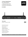 1
1
-
 2
2
-
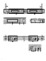 3
3
-
 4
4
-
 5
5
-
 6
6
-
 7
7
-
 8
8
-
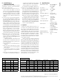 9
9
-
 10
10
-
 11
11
-
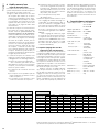 12
12
-
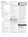 13
13
-
 14
14
-
 15
15
-
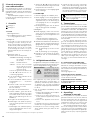 16
16
-
 17
17
-
 18
18
-
 19
19
-
 20
20
-
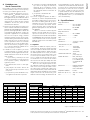 21
21
-
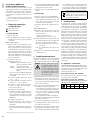 22
22
-
 23
23
-
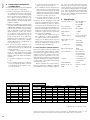 24
24
-
 25
25
-
 26
26


En otros idiomas
- français: Monacor TXS-920 Manuel utilisateur
- italiano: Monacor TXS-920 Manuale utente
- Deutsch: Monacor TXS-920 Benutzerhandbuch
- Nederlands: Monacor TXS-920 Handleiding
- polski: Monacor TXS-920 Instrukcja obsługi
Documentos relacionados
Otros documentos
-
IMG STAGELINE TXS-1820 Manual de usuario
-
-
-
-
JTS US-8001D/1 Manual de usuario
-
IMG STAGELINE 25.5350 Manual de usuario
-
-
IMG STAGELINE 25.7310 Manual de usuario
-
-