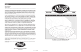
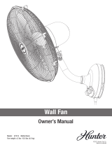
El Hunter Fan Ventilation Hood 90064 es un ventilador de baño con luz y luz nocturna que proporciona una ventilación potente y eficiente para su baño. Con una clasificación de flujo de aire de 110 CFM, puede mover una gran cantidad de aire para eliminar la humedad y los olores de manera rápida y efectiva. El ventilador también cuenta con una luz LED brillante que proporciona una iluminación brillante para su baño, y una luz nocturna suave que proporciona una iluminación tenue cuando es necesario.
El Hunter Fan Ventilation Hood 90064 es un ventilador de baño con luz y luz nocturna que proporciona una ventilación potente y eficiente para su baño. Con una clasificación de flujo de aire de 110 CFM, puede mover una gran cantidad de aire para eliminar la humedad y los olores de manera rápida y efectiva. El ventilador también cuenta con una luz LED brillante que proporciona una iluminación brillante para su baño, y una luz nocturna suave que proporciona una iluminación tenue cuando es necesario.


-
 1
1
-
 2
2
-
 3
3
-
 4
4
-
 5
5
-
 6
6
-
 7
7
-
 8
8
-
 9
9
-
 10
10
-
 11
11
-
 12
12
-
 13
13
-
 14
14
-
 15
15
-
 16
16
-
 17
17
-
 18
18
-
 19
19
-
 20
20
-
 21
21
-
 22
22
-
 23
23
-
 24
24
-
 25
25
-
 26
26
-
 27
27
-
 28
28
-
 29
29
-
 30
30
-
 31
31
-
 32
32
-
 33
33
-
 34
34
-
 35
35
-
 36
36
-
 37
37
-
 38
38
-
 39
39
-
 40
40


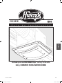
Hunter Fan Ventilation Hood 90064 Manual de usuario
- Tipo
- Manual de usuario
El Hunter Fan Ventilation Hood 90064 es un ventilador de baño con luz y luz nocturna que proporciona una ventilación potente y eficiente para su baño. Con una clasificación de flujo de aire de 110 CFM, puede mover una gran cantidad de aire para eliminar la humedad y los olores de manera rápida y efectiva. El ventilador también cuenta con una luz LED brillante que proporciona una iluminación brillante para su baño, y una luz nocturna suave que proporciona una iluminación tenue cuando es necesario.
en otros idiomas
Artículos relacionados
-
Hunter Fan 90067 El manual del propietario
-
 Hunter Fan 90061 El manual del propietario
-
 Hunter Fan 90063 El manual del propietario
-
 Hunter Fan 83006 Manual de usuario
-
 Hunter Fan 41953-01 El manual del propietario
-
 Hunter Fan 82500 El manual del propietario
-
 Hunter Fan 41953-01 Manual de usuario
-
 Hunter Fan 97318 El manual del propietario
-
 Hunter Fan 27179 Manual de usuario
-
 Hunter Fan 83006 Manual de usuario


