Black Box IC1023A Instrucciones de operación
- Tipo
- Instrucciones de operación
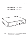
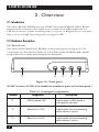
Black Box IC1023A es una herramienta que te permitirá conectar hasta 8 periféricos no compatibles con USB a un bus USB. Es una forma sencilla de añadir puertos serie RS-232 a tu ordenador sin necesidad de instalar tarjetas, puertos de E/S o IRQ.
Algunas aplicaciones comunes para el Black Box IC1023A son:
- Conexión de impresoras, escáneres y otros periféricos serie a un ordenador USB.
- Control de dispositivos industriales y científicos a través de una conexión serie.
- Creación de una red serie para conectar varios dispositivos.
- Ampliación del número de puertos serie disponibles en un ordenador.


-
 1
1
-
 2
2
-
 3
3
-
 4
4
-
 5
5
-
 6
6
-
 7
7
-
 8
8
-
 9
9
-
 10
10
-
 11
11
-
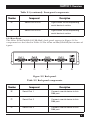 12
12
-
 13
13
-
 14
14
-
 15
15
-
 16
16
-
 17
17
-
 18
18


Black Box IC1023A Instrucciones de operación
- Tipo
- Instrucciones de operación
Black Box IC1023A es una herramienta que te permitirá conectar hasta 8 periféricos no compatibles con USB a un bus USB. Es una forma sencilla de añadir puertos serie RS-232 a tu ordenador sin necesidad de instalar tarjetas, puertos de E/S o IRQ.
Algunas aplicaciones comunes para el Black Box IC1023A son:
- Conexión de impresoras, escáneres y otros periféricos serie a un ordenador USB.
- Control de dispositivos industriales y científicos a través de una conexión serie.
- Creación de una red serie para conectar varios dispositivos.
- Ampliación del número de puertos serie disponibles en un ordenador.
En otros idiomas
Documentos relacionados
-
Black Box IC1102A Manual de usuario
-
Black Box HD6224A Manual de usuario
-
-
Blackbox KVXLC-100, KVXLCF-100 Manual de usuario
-
-
Black Box IC188A Manual de usuario
-
Black Box ME660A-MSC-R2 Manual de usuario
-