Black Box ME800A-R4 El manual del propietario
- Tipo
- El manual del propietario

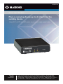
Place a receiving device up to 4 miles from the
sending device.
Select DCE or DTE via a DIP switch, so you won’t need special cables.
Product Group Title™
Order toll-free in the U.S.: Call 877-877-BBOX (outside U.S. call 724-746-5500)
FREE technical support 24 hours a day, 7 days a week: Call 877-877-2269 or fax
724-746-0746 • Mailing address: Black Box Corporation, 1000 Park Drive, Lawrence,
PA 15055-1018 • Web site: www.blackbox.com • E-mail: info@blackbox.com
Customer
Support
Information
March 2009
codes codes
codes codes
codes codes
Short-Haul Modem
ME800A-R4

Page 2 877-877-2269 | blackbox.com
Trademarks Used in this Manual
Trademarks Used in this Manual
Black Box and the Double Diamond logo are registered trademarks of
BB Technologies, Inc.
UL Is a registered trademark of Underwriters Laboratories.
Any other trademarks mentioned in this manual are acknowledged to be
the property of the trademark owners.

Page 3
877-877-2269 | blackbox.com
FCC and IC RFI Statements/NOM Statement
FEDERAL COMMUNICATIONS COMMISSION AND
INDUSTRY CANADA RADIO FREQUENCY INTERFERENCE STATEMENTS
This equipment generates, uses, and can radiate radio-frequency energy,
and if not installed and used properly, that is, in strict accordance with the
manufacturer’s instructions, may cause inter ference to radio communication.
It has been tested and found to comply with the limits for a Class A computing
device in accordance with the specifications in Subpart B of Part 15 of FCC rules,
which are designed to provide reasonable protection against such interference
when the equipment is operated in a commercial environment. Operation of
this equipment in a residential area is likely to cause interference, in which case
the user at his own expense will be required to take whatever measures may be
necessary to correct the interference.
Changes or modifications not expressly approved by the party responsible
for compliance could void the user’s authority to operate the equipment.
This digital apparatus does not exceed the Class A limits for radio noise
emis sion from digital apparatus set out in the Radio Interference Regulation
of Industry Canada.
Le présent appareil numérique n’émet pas de bruits radioélectriques dépassant les
limites applicables aux appareils numériques de la classe A prescrites dans le
Règlement sur le brouillage radioélectrique publié par Industrie Canada.
Normas Oficiales Mexicanas (NOM)
Electrical Safety Statement
INSTRUCCIONES DE SEGURIDAD
1. Todas las instrucciones de seguridad y operación deberán ser leídas antes
de que el aparato eléctrico sea operado.
2. Las instrucciones de seguridad y operación deberán ser guardadas para
referencia futura.
3. Todas las advertencias en el aparato eléctrico y en sus instrucciones de
operación deben ser respetadas.
4. Todas las instrucciones de operación y uso deben ser seguidas.

Page 4 877-877-2269 | blackbox.com
NOM Statement
5. El aparato eléctrico no deberá ser usado cerca del agua — por ejemplo,
cerca de la tina de baño, lavabo, sótano mojado o cerca de una alberca,
etc.
6. El aparato eléctrico debe ser usado únicamente con carritos o pedestales
que sean recomendados por el fabricante.
7. El aparato eléctrico debe ser montado a la pared o al techo sólo como sea
recomendado por el fabricante.
8. Servicio — El usuario no debe intentar dar servicio al equipo eléctrico más allá
lo descrito en las instrucciones de operación. Todo otro servicio deberá ser
referido a personal de servicio calificado.
9. El aparato eléctrico debe ser situado de tal manera que su posición no
interfiera su uso. La colocación del aparato eléctrico sobre una cama, sofá,
alfombra o superficie similar puede bloquea la ventilación, no se debe
colocar en libreros o gabinetes que impidan el flujo de aire por los orificios
de ventilación.
10. El equipo eléctrico deber ser situado fuera del alcance de fuentes de calor
como radiadores, registros de calor, estufas u otros aparatos (incluyendo
amplificadores) que producen calor.
11. El aparato eléctrico deberá ser connectado a una fuente de poder sólo
del tipo descrito en el instructivo de operación, o como se indique en el
aparato.
12. Precaución debe ser tomada de tal manera que la tierra fisica y la
polarización del equipo no sea eliminada.
13. Los cables de la fuente de poder deben ser guiados de tal manera que no
sean pisados ni pellizcados por objetos colocados sobre o contra ellos,
poniendo particular atención a los contactos y receptáculos donde salen
del aparato.
14. El equipo eléctrico debe ser limpiado únicamente de acuerdo a las
recomendaciones del fabricante.
15. En caso de existir, una antena externa deberá ser localizada lejos de las
lineas de energia.
16. El cable de corriente deberá ser desconectado del cuando el equipo no sea
usado por un largo periodo de tiempo.

Page 5
877-877-2269 | blackbox.com
NOM Statement
17. Cuidado debe ser tomado de tal manera que objectos liquidos no sean
derramados sobre la cubierta u orificios de ventilación.
18. Servicio por personal calificado deberá ser provisto cuando:
A: El cable de poder o el contacto ha sido dañado; u
B: Objectos han caído o líquido ha sido derramado dentro del aparato; o
C: El aparato ha sido expuesto a la lluvia; o
D: El aparato parece no operar normalmente o muestra un cambio en su
desempeño; o
E: El aparato ha sido tirado o su cubierta ha sido dañada.

Page 6 877-877-2269 | blackbox.com
Table of Contents
Table of Contents
1. Specifications ...............................................................................................7
2. Introduction .................................................................................................8
3. Installation ..................................................................................................10
4. Troubleshooting .........................................................................................15

Page 7
877-877-2269 | blackbox.com
Chapter 1: Specifications
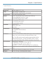
1. Specifications
Technical Specifications
Approvals Power supply: UL®, CSA
Data Flow Control: X-ON/X-OFF;
Data Format: Asynchronous, full-duplex
Interconnect Two-pair twisted-pair cable
Speed Up to 115,200 bps at up to 4000 feet (1250 m);
Up to 57,600 bps at up to 1 mile;
Up to 9600 bps at up to 4 miles
User Controls (1) 4-position DIP switch,
(1) DCE/DTE slide switch,
(1) push-button switch
Interface EIA RS-232-C;
CCITT V.24, V.28;
ISO 2110
Connectors (1) DB9 female;
(1) 4-position terminal block;
(1) RJ-11;
(1) DC power jack
Indicators TX: This dual Red/Green LED will be green when the Receive
Data is low, and red when the Receive Data is high.
RX: This LED can be used to verify proper polarity of the
interconnecting lines: it should be green when no data
is being transmitted. Red indicates improper line polarity.
Environment Temperature Tolerance:
Operating: 23 to 86° F (-5 to +30° C);
Storage: 23 to 140° F (-5 to +60° C);
Humidity: 0 to 95% relative humidity, non-condensing
Power Wallmount power supply: 9 VDC, 500 mA, 115 VAC, UL,
CSA
Dimensions 1.5"H x 5.2"W x 5.2"D (3.8 x 13.2 x 13.2 cm)
Weight 1.4 lb. (0.6 kg), including power supply

Page 8 877-877-2269 | blackbox.com
Chapter 2: Introduction
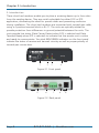
2. Introduction
These short-haul modems enable you to place a receiving device up to four miles
from the sending device. They are switch-selectable for either DCE or DTE
application, eliminating the need for special cables and preventing confusion
during installation. The short-haul modems are connected with twisted-pair cable,
using a 4-position terminal block or RJ-11. The units are optically isolated to
provide protection from differences in ground potential between the units. The
units provide line status (Data Carrier Detect when DCE is selected and Data
Terminal Ready when DTE is selected) to indicate that the remote unit is online
and ready to communicate. Two dual RED/GREEN indicators on the front panel
indicate the status of receive and transmit circuitry as well as proper polarity of
twisted-pair connections.
1 2 3 4
Figure 2-1. Front panel.
5 6 7 8 9
Figure 2-2. Back panel.

Page 9
877-877-2269 | blackbox.com
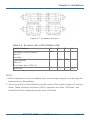
Chapter 2: Introduction
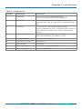
Table 2-1. Components.
Number Component Description
1Pushbutton Press this button for Loopback operation.
The button is not pressed in Normal operation.
2(2) TX LEDs This dual Red/Green LED will be green when the
Received Data is low, and red when the Received Data is
high.
3(2) RX LEDs This LED can be used to verify proper polarity
of the interconnecting lines: it should be green when no
data is being transmitted. Red indicates improper line
polarity.
4DCE/DTE DIP switch Slide left to configure the modem as a DCE.
Slide right to configure the modem as a DTE.
5(1) DB9 connector Links to RS-232 interface.
64-position DIP switch S3 See Table 3-6.
7Terminal block Interconnect
8Power connector 9-VDC, 500 mA power connector
9RJ-11 interconnect 6-position connector

Page 10 877-877-2269 | blackbox.com
Chapter 3: Installation
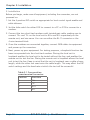
3. Installation
Before you begin, make sure all equipment, including the converters, are not
powered on.
1. Set the 4-position DIP switch as appropriate for local control signal enable and
cable distance.
2. Set the slide switch for either DCE to connect to a PC or DTE to connect to a
modem.
3. Connect the two short-haul modems with twisted-pair cable, making sure to
connect TX+ and TX- on the local unit to RX+ and RX- respectively on the
remote unit, and vice versa. You can use either the RJ-11 connector or the
4-wire terminal block.
4. Once the modems are connected together, connect DB9 cables to equipment
and power up the converters.
5. Next, power up your equipment. For testing purposes, a loopback function has
been incorporated into the short-haul modem. Placing the local unit in
loopback enables the local unit to be tested without the line, and enables the
remote unit to test the line. Placing the remote unit in loopback allows the local
unit to test the line. Keep in mind that the unit in loopback sees a cable of zero
length, while the other unit sees twice the cable length. This may affect the DIP
switch settings and the baud rate at which the test will be successful.
Table 3-1. Four-position
screw terminal connector.
Position Function
1 TX+
2TX-
3 RX+
4RX-

Page 11
877-877-2269 | blackbox.com
Chapter 3: Installation
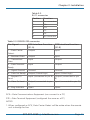
Table 3-2.
RJ-11 connector
Position Function
1No connection
2 RX+
3 TX+
4TX-
5RX-
6No connection
Table 3-3. DB9 RS-232 connector
Pin–Signal DCE Interface Function
(S1-A)
DTE Interface Function
(S1-B)
1 - Data Carrier
Detect
Output Input
2 - Received Data Output Input
3 - Transmitted
Data
Input Output
4 - Data Terminal
Ready
Input Output
5 - Signal Ground Ground Ground
6 - Data Set Ready Output (Pulled High) Input (Pulled High)
7 - Request To
Send
Input (connected to pin 8) Output (connected to pin
8)
8 - Clear To Send Output (connected to pin
7)
Input (connected to pin 7)
9 - Ring Indicator Open Open
DCE—Data Communications Equipment (can connect to a PC)
DTE—Data Terminal Equipment (configured the same as a PC)
NOTES:
1. When configured as DCE, Data Carrier Detect will be active when the remote
unit is driving the line.

Page 12 877-877-2269 | blackbox.com
Chapter 3: Installation
NOTES (continued):
2. When configured as DCE, Data Terminal Ready and Request to Send signals
may be used to disable the line driver (see S3). The remote unit will sense this
condition and its Data Carrier Detect signal will become negative.
3. When configured as DTE, Data Terminal Ready will be active when the remote
unit is driving the line.
4. When configured as DTE, Data Carrier Detect and Clear to Send signals may be
used to disable the line driver (see S3). The remote unit will sense this condition
and its Data Terminal Ready signal will become inactive.
Switches
S1 2-position slide switch (DTE/DCE)
S2 2-position push button switch (loopback); Push button will be in “out”
position for loopback.
S3 4-position DIP switch (option switches)
Table 3-4. S1 switch.
Position Function (See description of RS-232 DB9 connector)
AConfigure as DCE for connection to PC serial port
BConfigure as DTE to simulate PC serial port output
Table 3-5. S2 switch.
Position Function (See Figure 3-2)
OUT Normal operation
IN Loopback
NOTE: When switch S2 is in the loopback position, the output of the local unit is
fed back to its input, and the line is looped back so the remote unit can
test the line integrity. The remote unit will actually see twice the distance
of the line. This should be taken into consideration when determining the
maximum baud rate at which the loopback test will be successful.
The local loopback path is compensated for zero length cable.

Page 13
877-877-2269 | blackbox.com
Chapter 3: Installation
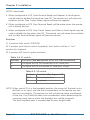
Figure 3-1. Loopback function.
Table 3-6. S3 switch (UP is OFF, DOWN is ON).
Switch Position 1 2 3 4
Hardware Control Enable
(Note 1)
Disabled
OFF
Line Distance
(Note 2)
Short (less than 1000 ft.)
OFF OFF
Reserved OFF
NOTES:
1. When hardware control is enabled, both control input signals must be high for
transmission to be enabled.
2. The long and short line distance switches control the current output of the line
driver. These switches should be OFF for distances less than 1000 feet, and
should be ON for distances greater than 1000 feet.

Page 14 877-877-2269 | blackbox.com
Chapter 3: Installation
Table 3-7. Indicators.
Indicator Function
TX The Green LED is on when the Receive Data is low, and the Red
LED is on when the Receive Data is high.
RX This LED can be used to verify proper polarity of the
interconnecting lines: it should be green when no data
is being transmitted. Red indicates improper line polarity.

Page 15
877-877-2269 | blackbox.com
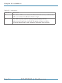
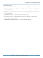
Chapter 4: Troubleshooting
4. Troubleshooting
If the units fail to operate, check the following before calling for technical support.
1. Are the units powered on? Check to see if the power supplies are plugged into
a working AC outlet.
2. Check to see if the interconnect wire is connected properly, TX+ to RX+, TX- to
RX-, at both ends.
3. Check that switch S3 is set for the proper cable length.
4. If hardware control is enabled, DTR and RTS must be high to enable data
transmission to the remote unit.
5. Check that the loopback switch S2 is in the Normal position.

Black Box Tech Support: FREE! Live. 24/7.
Tech support the
way it should be.
Great tech support is just 60 seconds away at
877-877-2269 or blackbox.com.
877-877-2269 | blackbox.com
About Black Box
Black Box provides an extensive range of networking and infrastructure products.
You’ll find everything from cabinets and racks and power and surge protection
products to media converters and Ethernet switches all supported by free, live 24/7
Tech support available in 60 seconds or less.
© Copyright 2021. Black Box Corporation. All rights reserved. Black Box® and the Double Diamond logo
are registered trademarks of BB Technologies, Inc. Any third-party trademarks appearing in this manual
are acknowledged to be the property of their respective owners.
me800a-r4_user_rev2.pdf
-
 1
1
-
 2
2
-
 3
3
-
 4
4
-
 5
5
-
 6
6
-
 7
7
-
 8
8
-
 9
9
-
 10
10
-
 11
11
-
 12
12
-
 13
13
-
 14
14
-
 15
15
-
 16
16


Black Box ME800A-R4 El manual del propietario
- Tipo
- El manual del propietario
en otros idiomas
- English: Black Box ME800A-R4 Owner's manual
Artículos relacionados
-
Black Box ME800A-R4 El manual del propietario
-
-
-
-
-
Black Box IC1023A Instrucciones de operación
-
Black Box LGC135A-R3 El manual del propietario
-
-
Black Box LGC215A-R2 Manual de usuario
-