
Overview and Description:
The FlexPointTM 232 converts between asynchronous
RS-232 and fiber with baud-rate auto-sensing, supporting
speeds of up to 115,200 baud. The following multimode
(MM) and single-mode (SM) models are described here:
Mounting and Cable Attachment:
The FlexPoint 232 can be solo-mounted using a wall-mounting
kit or the DIN-Rail kit. It can also be rack-mounted using a
5-position shelf or a high-density 14-unit FlexPoint Powered
Chassis.
RS-232 Cable Attachment:
Attach the FlexPoint 232 port via a male DB9 terminated or
unterminated straight through RS-232 serial cable to a DTE
or DCE device.
Note: Use RS-232 cables that are compliant with the
specifications that are outlined in RS-232 cable
specifications.
Fiber Optic Cable Attachment:
Connect the fiber cables between the two FlexPoint 232
converters. The transmit (Tx) must attach to the receive
side and the receive (Rx) must attach to the transmit side.
Note: Use fiber cables that are compliant with the
specifications that are outlined in fiber cable specifications.
Switch Settings:
DB9 to DTE / DB9 to DCE Switch:
When connecting the RS-232 cable to terminal equipment
such as a computer or controller, set the switch to “DTE”,
up. When connecting to communication equipment such
as a modem or printer, set the switch to “DCE”, down
(factory setting).
(Please refer to pin assignments for more detailed information)
Fiber Loopback Switch:
This switch will allow the entire fiber segment to be tested at
either of the FlexPoint 232 converters without having to set
switches on both units simultaneously. When this switch is
set to “Fiber Loopback”, the local unit’s fiber Tx port will be
encoded to carry a remote loopback protocol over the fiber
cable. This remote loopback protocol will set the far end
FlexPoint 232 converter to a loopback mode of operation
and return a signal over the fiber cable to the originating
unit. An LED on the local and remote FlexPoint 232
converters will blink fast to show a confirmation that the
fiber segment is communicating properly between the
converters. A slow blink will indicate an error condition over
the fiber segment. By returning the switch to the “normal”
position the converters will resume to normal operation.
Fiber Cable Specifications:
Multimode (standard)
Cable:
Wavelength:
Max Distance:
62.5/125, 100/140 μm
850nm
2.5km/1.5 mi.
62.5/125, 100/140 μm
1310nm
5km/3.1 mi.
9/125 μm
1310nm
28km/16.8 mi.
Multimode (long-haul)
Cable:
Wavelength:
Max Distance:
Singlemode
Cable:
Wavelength:
Max Distance:
RS-232 Cable Specifications:
Gauge 22 to 24 AWG
Mutual Capacitance 12 to 50 pF/ft.
Maximum Distance 15.2 m/50 ft.
TRADEMARKS
All applied-for and registered trademarks are the property
of their respective owners.
FEDERAL COMMUNICATIONS COMMISSION AND
CANADIAN DEPARTMENT OF COMMUNICATIONS
RADIO FREQUENCY INTERFERENCE STATEMENTS
This equipment generates, uses, and can radiate radio
frequency energy and if not installed and used properly, that
is, in strict accordance with the manufacturer’s instructions,
may cause interference to radio communication. It has been
tested and found to comply with the limits for a Class A
computing device in accordance with the specifications in
subpart J of Part 15 of FCC rules, which are designed to
provide reasonable protection against such interference when
the equipment is operated in a commercial environment.
Operation of this equipment in a residential area is likely to
be cause interference, in which case the user at his own
expense will be required to take whatever measures may be
necessary to correct the interference.
Changes or modifications not expressly approved by the
party responsible for compliance could void the user’s
authority to operate the equipment.
This digital apparatus does not exceed the Class A limits
for radio noise emission from digital apparatus set out in
the Radio Interference Regulation of the Canadian
Department of Communications.
Le présent appareil numérique n’émet pas de bruits
radioélectriques dépassant les limites applicables aux
appareils numéirques de las classe A prescrites dans le
Règlement sur le brouillage radioélectrique publié par le
ministère des Communications du Canada.
NORMAS OFICIALES MEXICANAS (NOM)
ELECTRICAL SAFETY STATEMENT
1. Todas las instrucciones de seguridad y operación deberán
ser leídas antes de que el aparato eléctrico sea operado.
2. Las instrucciones de seguridad y operación deberán ser
guardadas para referencia futura.
3. Todas las advertencias en el aparato eléctrico y en sus
instrucciones de operación deben ser respetadas.
4. Todas las instrucciones de operación y uso deben ser seguidas.
5. El aparato eléctrico no deberá ser usado cerca del agua—
por ejemplo, cerca de la tina de baño, lavabo, sótano mojado
o cerca de una alberca, etc.
6. El aparato eléctrico debe ser usado únicamente con carritos
o pedelstales que sean recomendados por el fabricante.
7. El aparato eléctrico debe ser montado a la pared o al techo
sólo como sea recomendado por el fabricante.
8. Servicio—El usuario no debe intentar dar servicio al
equipo eléctrico más allá a lo descrito en las instrucciones
de operación. Todo otro servicio deberá ser referido a
personal de servicio calificado.
9. El aparato eléctrico debe ser situado de tal manera que su
posición no interfiera su uso. La colocación del aparato
eléctrico sobre una cama, sofá, alfombra or superficie
similar puede bloquea la ventilación, no se debe colocar
en libreros o gabinetes que impidan el flujo de aire por
los orificios de ventilación.
10. El equipo eléctrico deber ser situado fuera del alcance de
fuentes de calor como radiadores, registros de calor,
estufas u ostros aparatos (incluyendo amplificadores) que
producen calor.
11. El aparato eléctrico deberá ser connectado a una fuente de
poder sólo del tipo descrito en el instructivo de operación,
o como se indique en el aparato.
12. Precación debe ser tomada de tal manera que la tierra fisica
y la polarización del equipo no sea eliminada.
13. Los cables de la fuente de poder deben ser guiados de tal
manera que no sean pisados ni pellizcados por objetos
colocados sobre o contra ellos, poniendo particular
atención a los contactos y receptáculos donde salen del
aparato.
14. El equipo eléctrico debe ser limpiado únicamente de
acuerdo a las recomendaciones del fabricante.
15. En caso de existir, una antena externa deberá ser localizada
lejos de las lineas de energia.
16. El cable de corriente deberá ser desconectado del cuando
el equipo no sea usado por un largo periodo de tiempo.
17. Cuidado debe ser tomado de tal manera que objectos
liquidos no sean derramados sobre la cubierta u orificios
de ventilación.
18. Servicio por personal calificado deberá ser provisto
cuando:
A: El cable de poder o el contacto ha sido dañado; u
B: Objectos han caído o líquido ha sido derramado dentro
del aparato; o
C: El aparato ha sido expuesto a la lluvia; o
D: El aparato parece no operar normalmente o muestra un
cambio en su desempeño; o
E: El aparto ha sido tirado o su cubierta ha sido dañada.
©Copyright 2006, 2023. Black Box Corporation. All rights
reserved.
1000 Park Drive · Lawrence, PA 15055-1018
724-746-5500 · Fax 724-746-0746
EN_NET_Manual_ME660A-MST-R2_Rev1_2301.pdf
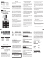
1 DCD
4 DTR
5 SGND
DSR 6
RTS 7
CTS 8
RI 9
2RD
3TD
LED Indicators:
LED Color Function Description
Power: Yellow Solid Power applied
DTE/DCE: Green Solid DTE selected
Yellow Solid DCE selected
DB9/232: Green Solid/Blink Link / Data received
Fiber Link: Green Solid Link
Green Blink fast Fiber loop-back is good
Green Blink slow Error in fiber loop-back
Switches:
Description Function
DB9 to DTE / DCE: Data Terminal / Data Communication
Fiber Loop-back: Loop-back / Normal
FlexPoint 232 Pin Assignments
NIPLANGISNIPRBBAETDECD
1tceteDreirraCataDDCDNITUO
2ataDdevieceRDRNITUO
3ataDdettimsnarTDTTUONI
4lanimreTataDRTDTUONI
5dnuorGlangiSDNGS--
6ydaeRteSataDRSDNITUO
7dneSoTtseuqeRSTRTUONI
8dneSoTraelCSTCNITUO
9rotacidnIgniRIRNITUO
U.S. Power Supply International Power Supply
ME661AE-MST
ME662AE-SSC
ME662AE-SST
ME661A-MST
ME662A-SSC
ME662A-SST
Order toll-free in the U.S.: Call 877-877-BBOX
(outside U.S. call 724-746-5500)
FREE technical support 24 hours a day, 7 days
a week; Call 724-746-5500 or fax 724-746-0746
Mailing address: Black Box Corporation,
1000 Park Drive, Lawrence, PA 15055-1018
Web site: www.blackbox.com
E-mail: [email protected]
CUSTOMER
SUPPORT
INFORMATION
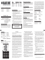
FlexPoint™ 232
Model Wavelength Fiber Distances
2.5km/1.5mi.
1310nm
1310nm 2.5km/1.5mi.
MM/ST 5km/3.1 mi.
SM/SC 28km/16.8mi.
SM/ST 28km/16.8mi.
ME660A-MSC-R2
ME660A-MST-R2
ME661A-MST 1310nm
ME662A-SSC 1310nm
ME662A-SST 1310nm
Power Adapter Notice:
1. When Using in a stand-alone configuration, this
product is intended to be and must be used only with
a Listed Direct Plug-In Power Unit marked
“Class VI” and rated at 9VDC, 1 Amp.
2. This product should always be used only with the
supplied power unit .
3. Models shipped with international power supplies are
capable of auto switching from 100-230V, and are
supplied with a U.S. type NEMA 5-15 power cable.
4. For products being shipped outside of the U.S., the
user is required to install a properly grounded IEC
320 appliance cable with a minimum rating of 10
AMPs.
5. User-supplied cables must meet the required safety
agency approvals, applicable international standards
and electrical ratings for the region.
WARNING!
Before inserting the Power Adapter, verify that
the power on the unit is appropriate for your
AC line voltage source.
MM/SC
MM/ST

encoded to carry a remote loopback protocol over the fiber
cable. This remote loopback protocol will set the far end
FlexPoint 232 converter to a loopback mode of operation
and return a signal over the fiber cable to the originating
unit. An LED on the local and remote FlexPoint 232
converters will blink fast to show a confirmation that the
fiber segment is communicating properly between the
converters. A slow blink will indicate an error condition over
the fiber segment. By returning the switch to the “normal”
position the converters will resume to normal operation.
Fiber Cable Specifications:
Multimode (standard)
Cable:
Wavelength:
Max Distance:
62.5/125, 100/140 μm
850nm
2.5km/1.5 mi.
62.5/125, 100/140 μm
1310nm
5km/3.1 mi.
9/125 μm
1310nm
28km/16.8 mi.
Multimode (long-haul)
Cable:
Wavelength:
Max Distance:
Singlemode
Cable:
Wavelength:
Max Distance:
RS-232 Cable Specifications:
Gauge 22 to 24 AWG
Mutual Capacitance 12 to 50 pF/ft.
Maximum Distance 15.2 m/50 ft.
TRADEMARKS
All applied-for and registered trademarks are the property
of their respective owners.
FEDERAL COMMUNICATIONS COMMISSION AND
CANADIAN DEPARTMENT OF COMMUNICATIONS
RADIO FREQUENCY INTERFERENCE STATEMENTS
This equipment generates, uses, and can radiate radio
frequency energy and if not installed and used properly, that
is, in strict accordance with the manufacturer’s instructions,
may cause interference to radio communication. It has been
tested and found to comply with the limits for a Class A
computing device in accordance with the specifications in
subpart J of Part 15 of FCC rules, which are designed to
provide reasonable protection against such interference when
the equipment is operated in a commercial environment.
Operation of this equipment in a residential area is likely to
be cause interference, in which case the user at his own
expense will be required to take whatever measures may be
necessary to correct the interference.
Changes or modifications not expressly approved by the
party responsible for compliance could void the user’s
authority to operate the equipment.
This digital apparatus does not exceed the Class A limits
for radio noise emission from digital apparatus set out in
the Radio Interference Regulation of the Canadian
Department of Communications.
Le présent appareil numérique n’émet pas de bruits
radioélectriques dépassant les limites applicables aux
appareils numéirques de las classe A prescrites dans le
Règlement sur le brouillage radioélectrique publié par le
ministère des Communications du Canada.
NORMAS OFICIALES MEXICANAS (NOM)
ELECTRICAL SAFETY STATEMENT
1. Todas las instrucciones de seguridad y operación deberán
ser leídas antes de que el aparato eléctrico sea operado.
2. Las instrucciones de seguridad y operación deberán ser
guardadas para referencia futura.
3. Todas las advertencias en el aparato eléctrico y en sus
instrucciones de operación deben ser respetadas.
4. Todas las instrucciones de operación y uso deben ser seguidas.
5. El aparato eléctrico no deberá ser usado cerca del agua—
por ejemplo, cerca de la tina de baño, lavabo, sótano mojado
o cerca de una alberca, etc.
6. El aparato eléctrico debe ser usado únicamente con carritos
o pedelstales que sean recomendados por el fabricante.
7. El aparato eléctrico debe ser montado a la pared o al techo
sólo como sea recomendado por el fabricante.
8. Servicio—El usuario no debe intentar dar servicio al
equipo eléctrico más allá a lo descrito en las instrucciones
de operación. Todo otro servicio deberá ser referido a
personal de servicio calificado.
9. El aparato eléctrico debe ser situado de tal manera que su
posición no interfiera su uso. La colocación del aparato
eléctrico sobre una cama, sofá, alfombra or superficie
similar puede bloquea la ventilación, no se debe colocar
en libreros o gabinetes que impidan el flujo de aire por
los orificios de ventilación.
10. El equipo eléctrico deber ser situado fuera del alcance de
fuentes de calor como radiadores, registros de calor,
estufas u ostros aparatos (incluyendo amplificadores) que
producen calor.
11. El aparato eléctrico deberá ser connectado a una fuente de
poder sólo del tipo descrito en el instructivo de operación,
o como se indique en el aparato.
12. Precación debe ser tomada de tal manera que la tierra fisica
y la polarización del equipo no sea eliminada.
13. Los cables de la fuente de poder deben ser guiados de tal
manera que no sean pisados ni pellizcados por objetos
colocados sobre o contra ellos, poniendo particular
atención a los contactos y receptáculos donde salen del
aparato.
14. El equipo eléctrico debe ser limpiado únicamente de
acuerdo a las recomendaciones del fabricante.
15. En caso de existir, una antena externa deberá ser localizada
lejos de las lineas de energia.
16. El cable de corriente deberá ser desconectado del cuando
el equipo no sea usado por un largo periodo de tiempo.
17. Cuidado debe ser tomado de tal manera que objectos
liquidos no sean derramados sobre la cubierta u orificios
de ventilación.
18. Servicio por personal calificado deberá ser provisto
cuando:
A: El cable de poder o el contacto ha sido dañado; u
B: Objectos han caído o líquido ha sido derramado dentro
del aparato; o
C: El aparato ha sido expuesto a la lluvia; o
D: El aparato parece no operar normalmente o muestra un
cambio en su desempeño; o
E: El aparto ha sido tirado o su cubierta ha sido dañada.
©Copyright 2006, 2023. Black Box Corporation. All rights
reserved.
1000 Park Drive · Lawrence, PA 15055-1018
724-746-5500 · Fax 724-746-0746
EN_NET_Manual_ME660A-MST-R2_Rev1_2301.pdf
1 DCD
4 DTR
5 SGND
DSR 6
RTS 7
CTS 8
RI 9
2RD
3TD
LED Indicators:
LED Color Function Description
Power: Yellow Solid Power applied
DTE/DCE: Green Solid DTE selected
Yellow Solid DCE selected
DB9/232: Green Solid/Blink Link / Data received
Fiber Link: Green Solid Link
Green Blink fast Fiber loop-back is good
Green Blink slow Error in fiber loop-back
Switches:
Description Function
DB9 to DTE / DCE: Data Terminal / Data Communication
Fiber Loop-back: Loop-back / Normal
FlexPoint 232 Pin Assignments
NIPLANGISNIPRBBAETDECD
1tceteDreirraCataDDCDNITUO
2ataDdevieceRDRNITUO
3ataDdettimsnarTDTTUONI
4lanimreTataDRTDTUONI
5dnuorGlangiSDNGS--
6ydaeRteSataDRSDNITUO
7dneSoTtseuqeRSTRTUONI
8dneSoTraelCSTCNITUO
9rotacidnIgniRIRNITUO
Overview and Description:
The FlexPointTM 232 converts between asynchronous
RS-232 and fiber with baud-rate auto-sensing, supporting
speeds of up to 115,200 baud. The following multimode
(MM) and single-mode (SM) models are described here:
Mounting and Cable Attachment:
The FlexPoint 232 can be solo-mounted using a wall-mounting
kit or the DIN-Rail kit. It can also be rack-mounted using a
5-position shelf or a high-density 14-unit FlexPoint Powered
Chassis.
RS-232 Cable Attachment:
Attach the FlexPoint 232 port via a male DB9 terminated or
unterminated straight through RS-232 serial cable to a DTE
or DCE device.
Note: Use RS-232 cables that are compliant with the
specifications that are outlined in RS-232 cable
specifications.
Fiber Optic Cable Attachment:
Connect the fiber cables between the two FlexPoint 232
converters. The transmit (Tx) must attach to the receive
side and the receive (Rx) must attach to the transmit side.
Note: Use fiber cables that are compliant with the
specifications that are outlined in fiber cable specifications.
Switch Settings:
DB9 to DTE / DB9 to DCE Switch:
When connecting the RS-232 cable to terminal equipment
such as a computer or controller, set the switch to “DTE”,
up. When connecting to communication equipment such
as a modem or printer, set the switch to “DCE”, down
(factory setting).
(Please refer to pin assignments for more detailed information)
Fiber Loopback Switch:
This switch will allow the entire fiber segment to be tested at
either of the FlexPoint 232 converters without having to set
switches on both units simultaneously. When this switch is
set to “Fiber Loopback”, the local unit’s fiber Tx port will be
Power Adapter Notice:
1. When Using in a stand-alone configuration, this
product is intended to be and must be used only with
a Listed Direct Plug-In Power Unit marked
“Class VI” and rated at 9VDC, 1 Amp.
2. This product should always be used only with the
supplied power unit .
3. Models shipped with international power supplies are
capable of auto switching from 100-230V, and are
supplied with a U.S. type NEMA 5-15 power cable.
4. For products being shipped outside of the U.S., the
user is required to install a properly grounded IEC
320 appliance cable with a minimum rating of 10
AMPs.
5. User-supplied cables must meet the required safety
agency approvals, applicable international standards
and electrical ratings for the region.
WARNING!
Before inserting the Power Adapter, verify that
the power on the unit is appropriate for your
AC line voltage source.
U.S. Power Supply International Power Supply
ME661AE-MST
ME662AE-SSC
ME662AE-SST
ME661A-MST
ME662A-SSC
ME662A-SST
Order toll-free in the U.S.: Call 877-877-BBOX
(outside U.S. call 724-746-5500)
FREE technical support 24 hours a day, 7 days
a week; Call 724-746-5500 or fax 724-746-0746
Mailing address: Black Box Corporation,
1000 Park Drive, Lawrence, PA 15055-1018
Web site: www.blackbox.com
E-mail: [email protected]
CUSTOMER
SUPPORT
INFORMATION
FlexPoint™ 232
Model Wavelength Fiber Distances
2.5km/1.5mi.
1310nm
1310nm 2.5km/1.5mi.
MM/ST 5km/3.1 mi.
SM/SC 28km/16.8mi.
SM/ST 28km/16.8mi.
ME660A-MSC-R2
ME660A-MST-R2
ME661A-MST 1310nm
ME662A-SSC 1310nm
ME662A-SST 1310nm
MM/SC
MM/ST
-
 1
1
-
 2
2


Black Box ME660A-MSC-R2 Manual de usuario
- Tipo
- Manual de usuario
- Este manual también es adecuado para
En otros idiomas
- français: Black Box ME660A-MSC-R2 Manuel utilisateur
- English: Black Box ME660A-MSC-R2 User manual
Documentos relacionados
-
Black Box MT660A-MM MM Manual de usuario
-
-
Black Box LMC213AE-MMSC-R2 Manual de usuario
-
-
-
Black Box IC1023A Instrucciones de operación
-
-
-
-