
49-80550-4 03-16 GE
Safety Instructions ............ 2
Operating Instructions
Light Controls ....................4
Vent Controls ....................4
Care and Cleaning
Metal Grease Filter ...............5
Charcoal Filter ...................5
Stainless Steel Surfaces ..........6
Light Bulbs .......................6
Installation Instructions
Installation Preparation ...........8
Vented to the Outside ...........16
Recirculating ....................21
Troubleshooting Tips ........27
Consumer Support
Warranty ....................... 29
Consumer Support .............. 30
Write the model and serial numbers here:
Model # ______________________
Serial # _______________________
You can find them on a label on the inside
of the hood.
Owner’s Manual and
Installation Instructions
English/Español
PV977
Island Chimney
Vent Hoods

2
49-80550-4
SAFETY PRECAUTIONS
IMPORTANT SAFETY INFORMATION.
READ ALL INSTRUCTIONS BEFORE USING.
WARNING
TO REDUCE THE RISK OF FIRE, ELECTRIC
SHOCK OR INJURY TO PERSONS, OBSERVE THE
FOLLOWING:
A. Use this unit only in the manner intended by the
manufacturer. If you have questions, contact the
manufacturer.
B. Before servicing or cleaning unit, switch power off at
service panel and lock the service disconnecting means
to prevent power from being switched on accidentally.
When the service disconnecting means cannot be locked,
securely fasten a prominent warning device, such as a
tag, to the service panel.
C. Do not use this unit with any solid-state speed control
device.
D. This unit must be grounded.
CAUTION
For general ventilating use only. Do not
use to exhaust hazardous or explosive materials and
vapors.
CAUTION
To reduce risk of fire and to properly
exhaust air, be sure to duct air outside. Do not vent
exhaust air into spaces within walls or ceilings or into
attics, crawl spaces or garages.
WARNING
TO REDUCE THE RISK OF INJURY TO
PERSONS IN THE EVENT OF A RANGE TOP GREASE
FIRE, OBSERVE THE FOLLOWING*:
A. SMOTHER FLAMES with a close-fitting lid, cookie sheet
or metal tray, then turn off the burner. BE CAREFUL TO
PREVENT BURNS. If the flames do not go out immediately,
EVACUATE AND CALL THE FIRE DEPARTMENT.
B. 1(9(53,&.83$)/$0,1*3$1³<RXPD\EHEXUQHG
C.'212786(:$7(5LQFOXGLQJZHWGLVKFORWKVRUWRZHOV³
a violent steam explosion will result.
D.8VHDQH[WLQJXLVKHU21/<LI
1.<RXNQRZ\RXKDYHD&ODVV$%&H[WLQJXLVKHUDQG\RX
already know how to operate it.
2. The fire is small and contained in the area where it
started.
3. The fire department is being called.
4. <RXFDQILJKWWKHILUHZLWK\RXUEDFNWRDQH[LW
* Based on “Kitchen Fire Safety Tips” published by NFPA.
READ AND SAVE THESE INSTRUCTIONS
This is the safety alert symbol. This symbol alerts you to potential hazards that can kill or hurt you
and others. All safety messages will follow the safety alert symbol and the word “DANGER”, “WARNING”, or
´&$87,21µ7KHVHZRUGVDUHGHILQHGDV
Indicates a hazardous situation which, if not avoided, will result in death or serious injury.
Indicates a hazardous situation which, if not avoided, could result in death or serious injury.
Indicates a hazardous situation which, if not avoided, could result in minor or moderate injury.
WARNING
DANGER
CAUTION

49-80550-4
3
SAFETY PRECAUTIONS
GEAppliances.com
WARNING
TO REDUCE THE RISK OF A RANGE TOP
GREASE FIRE:
A. Never leave surface units unattended at high settings.
Boilovers cause smoking and greasy spillovers that may
ignite. Heat oils slowly on low or medium settings.
B. Always turn hood ON when cooking on high heat or
when flambéing food (i.e. Crepes Suzette, Cherries Jubilee,
Peppercorn Beef Flambé).
C. Clean ventilating fans frequently. Grease should not be
allowed to accumulate on fan or filter.
D. Use proper pan size. Always use cookware appropriate
for the size of the surface element.
WARNING – TO REDUCE THE RISK OF
FIRE, ELECTRIC SHOCK OR INJURY TO PERSONS,
OBSERVE THE FOLLOWING:
A. Installation work and electrical wiring must be done
by qualified person(s) in accordance with all applicable
codes and standards, including fire-rated construction.
B. Sufficient air is needed for proper combustion and
exhausting of gases through the flue (chimney) of fuel
burning equipment to prevent back drafting. Follow
the heating equipment manufacturer’s guidelines
and safety standards, such as those published by the
National Fire Protection Association (NFPA), the American
Society for Heating, Refrigeration and Air Conditioning
Engineers (ASHRAE) and the local code authorities. When
applicable, install any makeup (replacement) air system
in accordance with local building code requirements. Visit
GEAppliances.com for available makeup air solutions.
C. When cutting or drilling into wall or ceiling, do not
damage electrical wiring and other hidden utilities.
D. Ducted fans must always be vented to the outdoors.
F. Turn off breaker to adjacent rooms while working.
WARNING
TO REDUCE THE RISK OF FIRE, USE
ONLY METAL DUCTWORK.
■ Do not attempt to repair or replace any part of your hood
unless it is specifically recommended in this manual.
All other servicing should be referred to a qualified
technician.
READ AND SAVE THESE INSTRUCTIONS

4
49-80550-4
MEMORY/OFF.7RVHWWKHPHPRU\
A. Press the MEMORY/OFF button.
B. Set your desired fan and light settings.
C. Press the MEMORY/OFF button again to save these
settings.
With your desired settings in memory, press the
MEMORY/OFF button to restore the fan and light
levels to their saved settings. These settings will
remain in memory until they are changed or loss of
power occurs.
To turn off the hood, press the MEMORY/OFF button.
LIGHT. Press + or – to increase or decrease light level
to desired setting. There are 2 light levels (LOW, HIGH)
and OFF. If you continue to press the + or – buttons,
the light will cycle back through the settings.
NOTE: Please check the lamps to ensure only 20W
lamps (maximum) are installed.
FAN. Press + or – to increase or decrease fan level
to your desired setting. There are 4 fan levels (LOW,
MED, HIGH, BOOST) and OFF. If you continue to press
the + or – buttons, the fan will cycle back through the
settings.
NOTE: There is an audible “beep” each time a button
is pressed. This is normal.
NOTE: The collars around the buttons will illuminate
when pressed. This is normal. The collars will
automatically turn off if the hood is turned off.
HEAT SENSOR:
This hood is equipped with a heat sensor that will turn
on the fan if excessive temperatures are detected (over
Û&Û)DERYHWKHFRRNLQJVXUIDFH7KHKRRGZLOO
return to its normal operation once the heat sensor detects
WHPSHUDWXUHVEHORZÛ&Û)
NOTE: If the hood is OFF or on LOW fan speed, the
WHPSHUDWXUHVDERYHÛ&Û)DUHGHWHFWHGWKHQWKHIDQ
will automatically adjust to MEDVSHHG<RXPD\DGMXVW
the fan speed to HIGH or BOOST, but you will not be able
to adjust the fan speed to LOW or OFF until temperatures
EHORZÛ&Û)DUHGHWHFWHG
NOTE: The collars around the buttons may not illuminate if
the heat sensor is activated. This is normal.
Using the hood controls.

49-80550-4
5
Care and cleaning of the vent hood. GEAppliances.com
Be sure electrical power is off and all surfaces are cool before cleaning or servicing any part of the vent hood.
Metal Grease Filter
The metal filter traps grease released
by foods from the cooktop. The filter
also helps prevent flames (from food,
grease) from damaging the inside of
the hood.
)RUWKLVUHDVRQWKHILOWHUPXVW$/:$<6
be in place when the hood is in use.
The grease filter is dishwasher-
safe and should be cleaned every 6
months, or as needed.
To remove:
Pull downward on the filter lock to
release the filter.
To replace:
Fit the tabs at the end of the filter
into the slots in left side of the filter
opening. Lift up the right side of the
filter and push gently until the filter
locks into place. Make sure the filter
lock is in the closed position to secure
the filter.
To clean, swish the filter in hot soapy
water and rinse in clean water or
wash it in the dishwasher. Do not use
abrasive cleansers.
NOTE: Some discoloration will occur in
the dishwasher.
Charcoal Filter
For recirculating installation only
If the model is not vented to the outside,
the air will be recirculated through a
disposable charcoal filter that helps
remove smoke and odors.
The charcoal filter should be replaced
when it is noticeably dirty or discolored
(usually after 6 to 12 months, depending
on hood usage).
NOTE: DO NOT rinse, or put charcoal
filter in an automatic dishwasher.
The charcoal filter cannot be cleaned.
It must be replaced.
Order Charcoal Filter WB02X11348.
To inquire about purchasing
replacement charcoal filters or to find
the location of a dealer nearest you,
SOHDVHFDOORXUWROOIUHHQXPEHU
National Parts Center
800.626.2002
To remove:
1. 5HPRYHWKHPHWDOILOWHU³VHH0HWDO
grease filter section.
2. Remove the charcoal filter by pushing
in on both locking tab handles to
release.
To replace:
1. Insert the charcoal filter into the
opening. Push the locking tab handles
toward the center and release to
engage the locking tabs.
2.5HSODFHWKHPHWDOILOWHU³VHH0HWDO
grease filter section.
Locking tab handle
Locking tab handle

6
49-80550-4
Care and cleaning of the vent hood.
Be sure electrical power is off and all surfaces are cool before cleaning or servicing any part of the vent hood.
Light Bulbs
CAUTION
Allow bulbs to cool before touching.
To change the light bulbs:
1. Remove the lamp lens cover by inserting a
small flat blade screwdriver into each of the
three slots and gently prying it free.
NOTE: Do not remove the outer trim ring
(lamp assembly).
2. Wear gloves. Do not touch the bulb with
your bare fingers. Skin oils can cause early
lamp failure.
3. Grasp the bulb and pull it straight out.
4. Replace with the same wattage. Early bulb
failure and damage to or failure of the
transformer may occur if wattage
is too high.
These 12-volt, 20-watt halogen bulbs with
a G4 base are available at specialty lighting
stores and home building centers.
To order replacement bulb no. WB01X10239,
contact the GE National Parts Center at
1.800.626.2002 or purchase from your local
retailer.
5. Replace lamp lens cover by inserting
the three retaining tabs into the three slots
and pressing firmly in place.
Use a small flat blade screwdriver
to remove the lamp lens cover.
Outer trim ring
(lamp assembly)
Do not remove
Bulb
Removable inner
lamp lens cover
127(0DNHVXUHWKHWDEVDUHLQVHUWHGLQWRWKHVORWV
Tab
Do not use a steel wool pad; it will scratch the
surface.
To clean the stainless steel surface, use warm
sudsy water or a stainless steel cleaner or
polish. Always wipe the surface in the direction
of the brush line. Follow the cleaner instructions
for cleaning the stainless steel surface. Cleaners
with oxalic acid such as Bar Keepers Friend
Soft Cleanser™ will remove surface rust,
tarnish, and small blemishes. To receive a $2.00
coupon for a trial sample of Bar Keepers Friend
Soft Cleanser™ follow the link below or scan
the QR Code.
ZZZEDUNHHSHUVIULHQGFRPJH
Use only a liquid cleanser free of grit and rub in
the direction of the brush lines with a damp soft
sponge.
To inquire about purchasing stainless steel
appliance cleaner or polish, or to find the
location of a dealer nearest you, please call our
WROOIUHHQXPEHU
National Parts Center
800.626.2002
GEApplianceParts.com
Stainless Steel Surfaces

49-80550-4
7
PRODUCT DIMENSIONS
Installation
Island Chimney Vent Hood
Instructions
* For supplied duct cover ceiling height for vented
installation and recirculating installation, refer to
the table on page 12.
µ
*Height to
ceiling
µ
µ
Questions? Call 800.GE.CARES (800.432.2737) or Visit our Website at: GEAppliances.com
BEFORE YOU BEGIN
Read these instructions completely and carefully.
•
IMPORTANT ³ Save these instructions
for local inspector’s use.
•
IMPORTANT ³ Observe all governing
codes and ordinances.
•
Note to Installer – Be sure to leave these
instructions with the Consumer.
• Note to Consumer – Keep these instructions
for future reference.
• Skill level – Installation of this vent hood requires
basic mechanical and electrical skills.
• Completion time – Approximately
4 to 6 hours
• Proper installation is the responsibility of the
installer.
• Product failure due to improper installation is not
covered under the Warranty.
FOR YOUR SAFETY:
WARNING
Before beginning the installation,
switch power off at service panel and lock the
service disconnecting means to prevent power
from being switched on accidentally. When the
service disconnecting means cannot be locked,
securely fasten a prominent warning device, such
as a tag, to the service panel.
CAUTION
Due to the weight and size of these
vent hoods and to reduce the risk of personal injury
or damage to the product,
TWO PEOPLE ARE REQUIRED FOR PROPER
INSTALLATION.
µ
INSTALLATION CLEARANCES
These vent hoods are
designed to be installed
onto a wall with no above
cabinets.
• Install these hoods
between the required
24” minimum and
36” recommended
maximum above the
cooking surface.
The vent hood must be
installed between the
required 24” minimum
and 36” recommended maximum above the
cooking surface. The hood installation height
above the cooking surface depends upon ceiling
height and duct cover limitations. The telescopic
duct cover conceals the ductwork running from
the top of the hood to the ceiling.
NOTE: Installation height should be measured from
the cooking surface to the lowest part of the hood.
This hood must be installed onto a wall. It can be
vented to the outdoors, or it can be installed for
recirculating operation. Recirculating Kit included
with hood.
µ
24” Required Min.
36” Recommended Max.
36” Typical
*Height to Ceiling
Vented Recirculating
Min µ µ
Max µ µ

8
49-80550-4
ADVANCE PLANNING
Duct Install Planning
• Determine the exact location of the vent hood.
• Use rigid metal ductwork only.
• Plan the route for venting exhaust to the outdoors.
To maximize the ventilation performance of the
YHQWV\VWHP
1. Minimize the duct run length and number of
transitions and elbows.
2. Maintain a constant duct size.
3. Seal all joints with duct tape to prevent any leaks.
4. Do not use any type of flexible ducting.
• Use the shortest and straightest duct route
possible.
• Install a roof cap with damper at the exterior
opening. Order the cap and any transitions and
length of duct needed in advance.
• When applicable, install any makeup (replacement)
air system in accordance with local building code
requirements. Visit GEAppliances.com for available
makeup air solutions.
Ceiling Framing for Adequate Support
• These vent hoods are heavy. Adequate structural
support must be provided. The ceiling structure
must be capable of supporting the weight of the
hood and any inadvertent user contact loads
(approximately 200 pounds). The hood support
frame will be supported by 2 x 4 cross framing.
• Installation will be easier if the vent hood is
installed before the cooktop or countertop below is
installed.
Duct Covers
• All models are shipped with duct covers. For
supplied duct cover ceiling heights for vented
installation and recirculating installation, refer to
table on page 12.
POWER SUPPLY
IMPORTANT - (Please read carefully)
WARNING
)253(5621$/6$)(7<7+,6$33/,$1&(0867%(
3523(5/<*5281'('
Remove house fuse or open circuit breaker before
beginning installation.
Do not use an extension cord or adapter plug with
this appliance. Follow National Electrical Codes or
prevailing local codes and ordinances.
Electrical Supply
This vent hood must be supplied with 120V, 60Hz,
and connected to an individual, properly grounded
branch circuit, and protected by a 15 or 20 amp
circuit breaker or time delay fuse.
• Wiring must be 2 wire with ground.
• If the electrical supply does not meet the above
requirements, call a licensed electrician before
proceeding.
• Route house wiring in the ceiling, as close to the
installation location as possible. Allow additional
length from ceiling joists to reach the junction box
on the bottom of the hood support frame.
• Connect the wiring to the house wiring in
accordance with local codes.
Grounding Instructions
The grounding conductor must be connected to
a ground metal, permanent wiring system, or an
equipment-grounding terminal or lead on the
hood.
WARNING
The improper connection of equipment-grounding
conductor can result in a risk of electric shock. Check
with a qualified electrician or service representative
if you are in doubt whether the appliance is properly
grounded.
Installation Preparation
PREPARE TO INSTALL THE HOOD

49-80550-4
9
PREPARE TO INSTALL THE HOOD
Installation Preparation
DO NOT use flexible plastic ducting.
NOTE: Any home ventilation system, such as a
ventilation hood, may interrupt the proper flow of
combustion air and exhaust required by fireplaces,
gas furnaces, gas water heaters and other
naturally vented systems. To minimize the chance
of interruption of such naturally vented systems,
follow the heating equipment manufacturer’s
guidelines and safety standards such as those
published by NFPA and ASHRAE. When applicable,
install any makeup (replacement) air system in
accordance with local building code requirements.
Visit GEAppliances.com for available makeup air
solutions.
This Hood Must Use an 8” Round Duct.
,W&DQ7UDQVLWLRQWRDµ[µ'XFW

10
49-80550-4
TOOLS AND MATERIALS REQUIRED
(NOT SUPPLIED)
Pliers
:LUHFXWWHUVWULSSHU
Metal snips
Spirit level
Aluminized
Duct tape
Safety glasses
120V 60Hz. 15 or 20 Amp,
2-wire with ground, properly
grounded branch circuit
Step ladder
Saber saw or Key Hole saw
Phillips screwdriver
Strain relief for
junction box
8” Round metal
duct, length to
suit installation
Hammer
(OHFWULFGULOOZLWKµ
bits, #2 Phillips head
Flashlight
UL listed wire nuts
Pencil and tape measure
REMOVE THE PACKAGING
CAUTION
Wear gloves to protect against sharp
edges.
• Remove the duct covers.
• Remove the hardware bag, literature package
and other boxed parts.
• Remove and properly discard the protective
plastic wrapping and other packaging materials.
Installation Preparation
PREPARE TO INSTALL THE HOOD

49-80550-4
11
CHECK INSTALLATION HARDWARE
Locate the hardware package packed with the hood and check contents.
RECIRCULATING KIT (Included)
Air deflector
36" HOOD
TEMPLATE
Cut one 1/2" Dia.
Wire Access Hole
as Needed
8-1/4" To
Centerline of
Pilot Holes
8-
1
/2
"
FRONT OF HOOD
Cut one 1/2" Dia.
Wire Access Hole
as Needed
Cut one 1/2" Dia.
Wire Access Hole
as Needed
Cut one 1/2" Dia.
Wire Access Hole
as Needed
Drill 3/16" Pilot Holes
Approx. 1-1/2" Deep
4 Places
8-1/4" To
Centerline of
Pilot Holes
10-5/16" To
Centerline of
Pilot Holes
10-5/16" To
Centerline of
Pilot Holes
31-14772
Printed in Mexico
12-08 JR
4 Wood
screws
73 Hood attachment screws
(70 required, 3 extra)
Duct covers
Charcoal filter
C
Duct cover supports (2)
Template
Ceiling support
Horizontal support
Upper vertical supports (4)
Lower vertical supports (4)
4 Duct cover clips
Stainless steel filter
D
B
E
A
A
B
C
D
E
HARDWARE PACKAGE
Locate and count
screws
Upper
Lower
PREPARE TO INSTALL THE HOOD
Installation Preparation

12
49-80550-4
PV977
Upper Duct Cover 29.92
Lower Duct Cover 25.98
Counter to Hood Height
Actual Ceiling
Height
*Possible VENTED
Installation Height
*Possible
RECIRCULATING
Installation Height
7’ 11” 24” 24”
8’ 0” 24” to 25” 24” to 25”
8’ 1” 24” to 26” 24” to 26”
8’ 2” 24” to 27” 24” to 27”
8’ 3” 24” to 28” 24” to 28”
8’ 4” 24” to 29” 24” to 29”
8’ 5” 24” to 30” 24” to 30”
8’ 6” 24” to 31” 24” to 31”
8’ 7” 24” to 32” 24” to 32”
8’ 8” 24” to 33” 24” to 33”
8’ 9” 24” to 34” 24” to 34”
8’ 10” 24” to 35” 24” to 35”
8’ 11” 24” to 36” 24” to 36”
9’ 0” 24” to 36” 24” to 36”
9’ 1” 24” to 36” 24” to 36”
9’ 2” 24” to 36” 24” to 36”
9’ 3” 24” to 36” 24” to 36”
9’ 4” 24” to 36” 24” to 36”
9’ 5” 25” to 36” 24” to 36”
9’ 6” 26” to 36” 24” to 36”
9’ 7” 27” to 36” 24” to 36”
9’ 8” 28” to 36” 24” to 36”
9’ 9” 29” to 36” 24” to 36”
9’ 10” 30” to 36” 25” to 36”
9’ 11” 31” to 36” 26” to 36”
10’ 0” 32” to 36” 27” to 36”
10’ 1” 33” to 36” 28” to 36”
10’ 2” 34” to 36” 29” to 36”
10’ 3” 35” to 36” 30” to 36”
10’ 4” 36” 31” to 36”
10’ 5” 32” to 36”
10’ 6” 33” to 36”
10’ 7” 34” to 36”
10’ 8” 35” to 36”
10’ 9” 36”
* based on 36” countertop height
INSTALLATION CLEARANCES
These vent hoods are designed to be installed onto
a wall with no above cabinets.
• Install these hoods between the required 24”
minimum and 36” recommended maximum
above the cooking surface.
The vent hood must be installed between the
required 24” minimum and 36” recommended
maximum above the cooking surface. The hood
installation height above the cooking surface
depends upon ceiling height and duct cover
limitations. The telescopic duct cover conceals
the ductwork running from the top of the hood to
the ceiling.
NOTE: Installation height should be measured from
the cooking surface to the lowest part of the hood.
This hood must be installed onto a wall. It can be
vented to the outdoors, or it can be installed for
recirculating operation. Recirculating Kit included
with hood.
24” Required Min.
36” Recommended Max.
36” Typical
Installation Preparation
PREPARE TO INSTALL THE HOOD

49-80550-4
13
Plan the Location of the Hood and Ductwork
• Use a plumb bob to check the location.
7KHFRXQWHUWRSFRRNWRSEHORZWKHKRRG
must be centered with the hood.
• The hood should extend beyond the front and rear
edge of the cooking appliance.
• The duct in the ceiling must be centered over
the cooktop.
CONSTRUCT CEILING SUPPORT
Top view – ceiling joists parallel to front of hood
16” Joist
spacing
µ
8” Duct
Front
of
hood
2x4 Cross framing
wood supports
Cooktop
outline
Align duct to
center of cooktop
Ceiling Support Structure
• At the hood location, install cross framing between
ceiling joists as shown. (2x4 wood supports are
required to support the weight of the hood.)
• Arrange cross framing in the ceiling to suit the
existing structure.
<RXUFHLOLQJMRLVWVZLOOEHOLNHRQHRIWKHIROORZLQJ
examples.
EXAMPLE A
Ceiling
Hood
ducting
centerline
Cooktop
Countertop
µ
Side view
Align with
center of
cooktop
Install cross-framing symmetrically
RYHUGXFWFRRNWRSFHQWHUOLQH
µ
µ
µ
Duct covers
PREPARE TO INSTALL THE HOOD
Installation Preparation

14
49-80550-4
Top view – ceiling joists run perpendicular to front of hood
Top view – ceiling joists at angle to front of hood
CONSTRUCT CEILING SUPPORT (Continued)
16” Joist
spacing
µ
8” Duct
Front
of
hood
Cooktop
outline
Align duct
to center
of cooktop
16” Joist
spacing
8” Duct
Cooktop
outline
Align duct
to center
of cooktop
EXAMPLE B
EXAMPLE C
Front
of hood
µ
Install cross-framing
V\PPHWULFDOO\RYHUGXFW
cooktop centerline
2x4 Cross
framing wood
supports
Install cross-framing
V\PPHWULFDOO\RYHUGXFWFRRNWRS
centerline
µ
µ
2x4 Cross
framing wood
supports
Installation Preparation
PREPARE TO INSTALL THE HOOD

49-80550-4
15
CONSTRUCT CEILING SUPPORT (Continued)
Ductwork for Installations Vented to the Outdoors
• Use the shortest and straightest duct route for
satisfactory performance.
• This vent hood must use 8” round rigid duct.
• Install the house ductwork to run horizontally
between ceiling joists or straight up through
the roof.
Finish the Ceiling
• Finish the ceiling surface. Be sure to mark location
of the ceiling joists and cross framing. Check to be
VXUHWKHFHLOLQJLVOHYHOXVHVKLPVLIQHFHVVDU\
• Secure each 2 x 4 block with at least four (4), #10
wood screws, 3” long (not supplied). Use 8 wood
screws total for the two supports.
• The cross framing must be accurately aligned
to assure correct positioning of the hood.
• The cross framing must be level in all directions.
Check with a spirit level and adjust if necessary.
IMPORTANT: The ceiling structure must be capable
of supporting the weight of the hood (approximately
200 pounds) and any inadvertent user contact loads.
The hood support frame will be supported by the
2 x 4 cross framing.
2 x 4 min.
Cross framing
Ceiling
joist
µ
8”
Duct
Ceiling joist
µ
2 x 4
Vent straight up
through the ceiling
PREPARE TO INSTALL THE HOOD
Installation Preparation

16
49-80550-4
• Align the template with the marks on the ceiling
and tape in place.
– Be sure the template is oriented correctly
with the front of the hood.
• Use a plumb bob to be sure the mounting holes
will provide parallel alignment with the countertop
below.
• Determine wire access hole location.
• Center punch all screw and determined wire hole
locations.
'ULOOSLORWKROHVLQWKHVFUHZORFDWLRQV8VHDµ
ELWDQGGULOODSSUR[LPDWHO\µGHHS
'ULOORQHµKROHIRUZLUHV
&XWWKHµGXFWRSHQLQJWKURXJKWKHFHLOLQJ
STEP 1 MOUNT TEMPLATE
STEP 2 INSTALL CEILING SUPPORT
• Using 4 wood screws provided, attach the ceiling
support to the ceiling over duct opening hole
using pilot holes drilled in step 1.
STEP 3 INSTALL LOWER VERTICAL
AND HORIZONTAL SUPPORTS
TO HOOD ASSEMBLY
• Using screws provided, attach the 4 lower
vertical supports to the hood assembly with 4
screws per support.
• Using screws provided, install the horizontal
support in the top outer holes of the vertical
supports.
36" HOOD
TEMPLATE
Cut one 1/2" Dia.
Wire Access Hole
as Needed
8-1/4" To
Centerline of
Pilot Holes
8-
1
/2"
FRONT OF HOOD
Cut one 1/2" Dia.
Wire Access Hole
as Needed
Cut one 1/2" Dia.
Wire Access Hole
as Needed
Cut one 1/2" Dia.
Wire Access Hole
as Needed
Drill 3/16" Pilot Holes
Approx. 1-1/2" Deep
4 Places
8-1/4" To
Centerline of
Pilot Holes
10-5/16" To
Centerline of
Pilot Holes
10-5/16" To
Centerline of
Pilot Holes
31-14772
Printed in Mexico
12-08 JR
Screws
Front
Installation Preparation
,167$//$7,21³9(17('727+(2876,'(

49-80550-4
17
STEP 5 INSTALL UPPER VERTICAL
SUPPORTS TO HOOD ASSEMBLY
• Determine how much of the upper vertical
supports will need to be above the lower supports
to accomplish the frame height determined in
step 4 for this installation.
• Using screws provided, attach the 4 upper vertical
supports to the lower vertical supports at the
position determined for frame height. The upper
vertical supports are mounted to the outside
of the lower supports.
STEP 4 DETERMINE FRAME HEIGHT
•Measure exact
ceiling height.
• Use this formula
to determine
your frame
KHLJKW
A-(B+C+D) =
Frame height E
where A is the
ceiling height, B
is the countertop
height, C is the
installation
height, D is the
height of the hood
measured from the
straight bottom
portion to the top at
the center.
24” Min.
36” Recommended Max.
36” Typical
Frame
height
µ
Ceiling
height
E
E
A
B
D
C
Installation Preparation
,167$//$7,21³9(17('727+(2876,'(

18
49-80550-4
STEP 6 CUT DUCT TO LENGTH
FOR VENTED INSTALLATION
• Measure from the hood exhaust opening to
the top of the supports as shown in the figure.
• Subtract any length of duct that is protruding
through the ceiling.
• Cut the 8” duct to the appropriate length. Attach
to ceiling duct using aluminized tape and screws.
STEP 7 INSTALL HOOD ASSEMBLY
TO CEILING SUPPORT
WARNING
Two people are required
to lift and position the hood onto the support.
• Lift the hood assembly up to the ceiling support.
Carefully fit the newly assembled duct over
exhaust opening on the hood assembly. The clips
on the ceiling support will snap into the large
openings on the upper vertical supports.
• Using the screws provided, attach the upper
vertical supports to the ceiling support, 4 screws
per side, for a total of 16 screws.
• Seal duct with aluminized duct tape.
Ceiling
support
Clips
Length of duct
needed minus the
length protruding
through the
ceiling.
Seal with
aluminized
duct tape
Installation Preparation
,167$//$7,21³9(17('727+(2876,'(

49-80550-4
19
STEP 9
INSTALL DUCT COVER SUPPORTS
• Attach the duct cover supports to the sides
of the horizontal and ceiling supports using
4 screws per duct cover support.
STEP 8 CONNECT ELECTRICAL
Verify that power is turned off at the source.
WARNING
If house wiring is not 2-wire
with a ground wire, a ground must be provided by
the installer. When house wiring is aluminum, be
sure to use U.L. approved anti-oxidant compound
and aluminum-to-copper connectors.
• Remove the 6 screws on the junction box cover
and the knockout on the top left side.
• Secure the house wiring to the junction box with
a strain relief (not provided).
• Connect the white lead to the branch circuit white lead.
• Connect the black lead to the branch circuit black lead.
&RQQHFWWKHJUHHQ\HOORZOHDGWRWKHEUDQFK
circuit green lead or bare ground lead.
• Secure all the connections with wire nuts on each
electrical connector.
• Push the wires into the junction box and replace
the cover. Be sure the wires are not pinched.
• Secure the junction box cover with the 6 original
screws.
Screws
Ceiling
support
Horizontal
support
Junction
box cover
Knockout
Duct cover
support
Installation Preparation
,167$//$7,21³9(17('727+(2876,'(

20
49-80550-4
STEP 10 INSTALL DUCT COVERS (CONT.)
• Using screws provided, secure the lower duct
covers to the hood assembly from the underside
of the hood.
STEP 11 INSTALL METAL GREASE FILTER
• Remove protective film on the grease filter.
NOTE: The charcoal filter is not required for this
installation.
• Fit the tabs at the end of the filter into the slots
in left side of the filter opening. Lift up the right
side of the filter and push gently until the filter
locks into place. Make sure the filter lock is in
the closed position to secure the filter.
• To remove the filter, pull downward on the filter
lock to release.
STEP 10 INSTALL DUCT COVERS
IMPORTANT: Two people are required to install
the duct covers.
NOTE: If you are installing this hood for recirculating
operation, place the duct covers onto the hood with
the venting slots at the top. If the hood is vented
to the outside, the holes should be positioned
on the bottom.
• Remove the protective film from all duct covers.
• Place one upper duct cover over the rear of the
support assembly. The tabs on the edges of the duct
cover will slide into a notch on the duct cover support.
When all 6 tabs on the duct cover are in the notches
on both of the duct cover supports, slide the duct
cover up so it sits on the duct cover support spring clip.
• Place a duct cover clip onto the bottom of the rear
lower duct cover locking the clip into place. Repeat
on the other side.
• Lower the duct cover into the recess on the hood,
being careful to hold the clip in place while lowering
the duct cover onto the hood assembly.
• Place the front lower duct cover into the recess
of the hood locking it onto the duct cover clip on the
rear cover.
• Place a duct cover clip at the top on each side
where the front and rear duct covers meet. This will
hold the rear and front covers together.
Duct cover clip
Left duct cover
Duct cover
support spring clip
Installation Preparation
,167$//$7,21³9(17('727+(2876,'(

49-80550-4
21
• Align the template with the marks on the ceiling
and tape in place.
– Be sure the template is oriented correctly
with the front of the hood.
• Use a plumb bob to be sure the mounting holes
will provide parallel alignment with the countertop
below.
• Determine wire access hole location.
• Center punch all screw and determined wire hole
locations.
'ULOOSLORWKROHVLQWKHVFUHZORFDWLRQV8VHDµ
ELWDQGGULOODSSUR[LPDWHO\µGHHS
'ULOORQHµKROHIRUZLUHV
STEP 1 MOUNT TEMPLATE
NOTE: Do not cut the duct opening shown on the
template for this recirculating installation.
36" HOOD
TEMPLATE
Cut one 1/2" Dia.
Wire Access Hole
as Needed
8-1/4" To
Centerline of
Pilot Holes
8-
1
/
2
"
FRONT OF HOOD
Cut one 1/2" Dia.
Wire Access Hole
as Needed
Cut one 1/2" Dia.
Wire Access Hole
as Needed
Cut one 1/2" Dia.
Wire Access Hole
as Needed
Drill 3/16" Pilot Holes
Approx. 1-1/2" Deep
4 Places
8-1/4" To
Centerline of
Pilot Holes
10-5/16" To
Centerline of
Pilot Holes
10-5/16" To
Centerline of
Pilot Holes
31-14772
Printed in Mexico
12-08 JR
STEP 3 INSTALL CEILING SUPPORT
AND DEFLECTOR ASSEMBLY
• Using the 4 wood screws provided, attach the
ceiling support using the pilot holes drilled in step 1.
Screws
STEP 2 INSTALL AIR DEFLECTOR
INTO CEILING SUPPORT
• Lay ceiling support on a firm surface, clip side up.
• Position the air deflector onto the ceiling support,
duct opening up and one of the open sides to what
will be the front of the hood assembly. The tabs
on the deflector will be to the outside of the ceiling
support.
• Using 2 screws provided,
secure the tabs on the
deflector to the ceiling
support.
Front
STEP 4 INSTALL LOWER VERTICAL
AND HORIZONTAL SUPPORTS
TO HOOD ASSEMBLY
• Using screws provided, attach the 4 lower
vertical supports to the hood assembly with
4 screws per support.
• Using screws provided, install the horizontal
support in the second outer holes of the vertical
supports.
Installation Preparation
,167$//$7,21³5(&,5&8/$7,1*

22
49-80550-4
STEP 5 DETERMINE FRAME HEIGHT
•Measure exact
ceiling height.
• Find the exact
frame height
required
on the chart
on page 12.
• Use this formula
to determine your
IUDPHKHLJKW
A-(B+C+D) =
Frame height
E where A is the
ceiling height, B
is the countertop
height, C is the height
determined by the
chart on page 12, D
is the height of the
hood measured from
the straight bottom
portion to the top
at the center.
24” Min.*
36” Recommended Max.*
36” Typical
Frame
height
µ
Ceiling
height
E
A
B
D
C
STEP 6 INSTALL UPPER VERTICAL
SUPPORT
• Using the screws provided, attach the 4 upper
vertical supports to the lower vertical supports
at the position determined for frame height.
The upper vertical supports are mounted to the
outside of the lower supports.
*See Chart on page 12.
E
Installation Preparation
,167$//$7,21³5(&,5&8/$7,1*

49-80550-4
23
STEP 7 DETERMINE DUCT LENGTH
AND INSTALL DUCT
• Measure from the hood exhaust opening to
the top of the supports as shown in the figure.
• Subtract the height of the air deflector.
• Cut the 8” duct to the appropriate length. Attach
to air deflector using aluminized tape and screws.
Length of duct
needed minus the
length protruding
through the ceiling.
STEP 8 INSTALL HOOD ASSEMBLY
TO CEILING SUPPORT
WARNING
Two people are required to lift and
position the hood onto the support.
• Carefully lift the hood assembly to the ceiling
support. The clips on the ceiling support will snap
into the openings on the vertical supports.
• Slip the duct over the exhaust opening.
• Using the screws provided, attach the upper
vertical supports to the ceiling support, 2 screws
per side for a total of 16 screws.
• Seal the air duct to the exhaust opening using
aluminized duct tape.
Ceiling
support
Air
deflector
Clips
Tape with
aluminized
duct tape
Installation Preparation
,167$//$7,21³5(&,5&8/$7,1*

24
49-80550-4
STEP 9 CONNECT ELECTRICAL
Verify that power is turned off at the source.
WARNING
If house wiring is not 2-wire with a
ground wire, a ground must be provided by the
installer. When house wiring is aluminum, be sure
to use U.L. approved anti-oxidant compound and
aluminum-to-copper connectors.
• Remove the 6 screws on the junction box cover
and the knockout on the top left side.
• Secure the house wiring to the junction box with
a strain relief (not provided).
• Connect the white lead to the branch circuit white lead.
• Connect the black lead to the branch circuit black lead.
&RQQHFWWKHJUHHQ\HOORZOHDGWRWKHEUDQFK
circuit green lead or bare ground lead.
• Secure all the connections with wire nuts on each
electrical connector.
• Push the wires into the junction box and replace
the cover. Be sure the wires are not pinched.
• Secure the junction box cover with the 6 original
screws.
STEP 10
INSTALL DUCT COVER SUPPORTS
• Attach the duct cover supports to the sides of the
horizontal and ceiling supports using 4 screws per
duct cover support.
Junction
box cover
Knockout
Screws
Ceiling
support
Horizontal
support
Duct cover
support
Installation Preparation
,167$//$7,21³5(&,5&8/$7,1*

49-80550-4
25
STEP 11 INSTALL DUCT COVERS
IMPORTANT: Two people are required to install
the duct covers.
NOTE: If you are installing this hood for recirculating
operation, place the duct covers onto the hood with
the venting slots at the top. If the hood is vented to
the outside, the holes should be positioned on the
bottom.
• Remove the protective film from all duct covers.
• Place one upper duct cover over the rear of the
support assembly. The tabs on the edges of the
duct cover will slide into a notch on the duct cover
support. When all 6 tabs on the duct cover are in the
notches on both of the duct cover supports, slide the
duct cover up so it sits on the duct cover support
spring clip.
Left duct
cover
Duct cover
support spring
clip
STEP 11 INSTALL DUCT COVERS (cont.)
• Place a duct cover clip onto the bottom of the
rear lower duct cover locking the clip into place.
Repeat on the other side.
• Lower the duct cover into the recess on the hood.
• Place the front lower duct cover into the recess of
the hood locking it onto the duct cover clip on the
rear cover.
• Place a duct cover clip on each side where the
front and rear duct covers meet. This will hold the
rear and front covers together.
Duct cover clip
• Using screws provided, secure the lower duct
covers to the hood assembly from the underside
of the hood.
Installation Preparation
,167$//$7,21³5(&,5&8/$7,1*

26
49-80550-4
STEP 12 INSTALL FILTERS
Charcoal Filter
Insert the charcoal filter into the opening.
Push the latch on both sides toward the center
and engage the flange.
Metal Grease Filter
• Remove the protective film on the grease filter.
• Fit the tabs at the end of the filter into the slots
in left side of the filter opening. Lift up the right
side of the filter and push gently until the filter
locks into place. Make sure the filter lock is
in the closed position to secure the filter.
• To remove the filter, pull downward on the filter
lock to release.
Installation Preparation
,167$//$7,21³5(&,5&8/$7,1*

49-80550-4
27
Before you call for service…
Troubleshooting Tips
Save time and money! Review the chart below first
and you may not need to call for service.
Problem Possible Causes What To Do
Fan/Light does not A house fuse may be blown • Replace fuse or reset circuit breaker.
operate when either or a circuit breaker tripped.
button is pressed
Fan does not operate The blower connector is loose • Disconnect power to the unit. Remove the filters
when fan + or – buttons or not plugged into its mating and look up at the blower. If the blower connector
or MEMORY/OFF button connector. plug is loose or you see the connector dangling,
is pressed the installer failed to plug it in securely. See the
Installation Instructions for the plug location and how
to plug in the connector.
Loud or abnormal Wrong duct size used in • This hood requires 8” minimum ducting to perform
airflow noise installation. optimally. Using smaller duct pipe will cause improper
venting. GE service technicians cannot correct this
issue if installed improperly.
Fan fails to circulate air Obstructions in duct work. • Make sure nothing is blocking the vent. Make sure
or moves air slower your wall or roof cap has a blade or door.
than normal and/or fan
Damper blade on wall or roof • Make sure damper swings freely. Damper blades may
is making loud or
cap may not be open. flip over and will not fully open when this happens.
abnormal airflow noise
Adjust to original position.
Metal grease filter and charcoal • Clean the metal grease filter and replace charcoal
filter (if present) may be dirty. filter (if present). See Care and Cleaning of the Vent
Hood.
Insufficient makeup • Sufficient makeup (replacement) air is required for
(replacement) air exhausting appliances to operate to rating. Check with
local building codes, which may require or strongly advise
the use of makeup air. Visit GEAppliances.com for available
makeup air solutions.
The hood controls are Control logic confused. • Disconnect power to the hood by resetting the circuit
not operating correctly breaker. Wait 30 seconds to allow controls to reset.
Early bulb failure Replacing bulbs with bare hands. • Replace bulbs while wearing gloves to keep skin oils
off bulbs.
• Bulb wattage is too high. Replace with correct
wattage.
Hood does not appear The memory feature of this • Follow procedures for setting the MEMORY/OFF
to operate when the hood has not been set. This is button. Adjust the Fan and Light settings to your
MEMORY/OFF button normal. preference.
is pressed. All collars
around the push buttons
are illuminated.

28
49-80550-4
Before you call for service…
Troubleshooting Tips
Save time and money! Review the chart below first
and you may not need to call for service.
Problem Possible Causes What To Do
Fan turned on by itself The heat sensor is activated. • This is normal when temperatures below the hood
and is in MED setting. are exceeding the heat sensor limits. Remove the heat
The fan setting can be source under the hood or wait until the hood cools to
adjusted but not to OFF. appropriate levels. The hood will automatically turn
itself off or return to its original setting once the heat
sensor detects the temperature has reached a safe
condition.
A collar around a push Push button may be stuck. • Check affected push button and ensure that it is not
button is not illuminating stuck. Call for service if problem persists.
when pressed.
Two or more collars Two or more push buttons • Check affected push buttons and ensure that they
around the push buttons may be stuck. are not stuck. Call for service if problem persists.
are not illuminating
when pressed.
Sequential presses This is normal. It is a feature • No action required.
of the LIGHT or FAN of the hood that the LIGHT
buttons will change and FAN buttons will cycle
the setting from lowest around through the settings
setting to OFF, to so that you can easily set
highest setting, to OFF, the controls to your desired
to the lowest setting. setting.

49-80550-4
29
GE Warranty
GEAppliances.com
All warranty service is provided by our Factory Service Centers, or an authorized Customer Care
®
technician.
To schedule service, on-line, visit us at www.geappliances.com/service_and_support/, or call 800.GE.CARES
(800.432.2737). Please have serial number and model number available when calling for service.
Servicing your appliance may require the use of the onboard data port for diagnostics. This gives a GE factory
service technician the ability to quickly diagnose any issues with your appliance and helps GE improve its products
by providing GE with information on your appliance. If you do not want your appliance data to be sent to GE, please
advise your technician not to submit the data to GE at the time of service.
For the period of one year from the date of the original purchase. GE will provide any part of the range which fails due
to a defect in materials or workmanship. During this limited one-year warranty, GE will also provide, free of charge, all
labor and in-home service to replace the defective part.
What GE will not cover:
Ŷ Service trips to your home to teach you how to use
the product.
Ŷ Improper installation, delivery or maintenance.
Ŷ Failure of the product if it is abused, misused,
modified or used for other than the intended purpose
or used commercially.
Ŷ Replacement of house fuses or resetting of circuit
breakers.
Ŷ Damage to the product caused by accident, fire,
floods or acts of God.
Ŷ Damage to finish, such as surface rust, tarnish, or
small blemishes not reported within 48 hours of
delivery.
Ŷ Incidental or consequential damage caused by
possible defects with this appliance.
Ŷ Damage caused after delivery.
Ŷ Product not accessible to provide required service.
Ŷ Service to repair or replace light bulbs, except for
LED lamps.
EXCLUSION OF IMPLIED WARRANTIES
Your sole and exclusive remedy is product repair as provided in this Limited Warranty. Any implied warranties,
including the implied warranties of merchantability or fitness for a particular purpose, are limited to one year or the
shortest period allowed by law.
This warranty is extended to the original purchaser and any succeeding owner for products purchased for home use
within the USA. If the product is located in an area where service by a GE Authorized Servicer is not available, you
may be responsible for a trip charge or you may be required to bring the product to an Authorized GE Service location
for service. In Alaska, the warranty excludes the cost of shipping or service calls to your home.
Some states do not allow the exclusion or limitation of incidental or consequential damages. This warranty gives you
specific legal rights, and you may also have other rights which vary from state to state. To know what your legal rights
are, consult your local or state consumer affairs office or your state’s Attorney General.
Warrantor: General Electric Company. Louisville, KY 40225
Extended Warranties: Purchase a GE extended warranty and learn about special discounts that are available while
your warranty is still in effect. You can purchase it on-line anytime
www.geappliances.com/service_and_support/shop-for-extended-service-plans.htm
or call 800.626.2224 during normal business hours. GE Consumer Home Services will still be there after your
warranty expires.
Register Your Appliance: Register your new appliance on-line at your convenience!
www.geappliances.com/service_and_support/register/
Timely product registration will allow for enhanced communication and prompt service under the terms of your warranty,
should the need arise. You may also mail in the pre-printed registration card included in the packing material.
Staple your receipt here. Proof of the original purchase
date is needed to obtain service under the warranty.
Thank You! ... for your purchase of a GE Brand appliance.

30
49-80550-4
Register Your Appliance GEAppliances.com
5HJLVWHU\RXUQHZDSSOLDQFHRQOLQH³DW\RXUFRQYHQLHQFHTimely product registration will allow for
enhanced communication and prompt service under the terms of your warranty, should the need arise.
<RXPD\DOVRPDLOLQWKHSUHSULQWHGUHJLVWUDWLRQFDUGLQFOXGHGLQWKHSDFNLQJPDWHULDO
Consumer Support.
GE Appliances Website
GEAppliances.com
Have a question or need assistance with your appliance? Try the GE Appliances Website 24 hours a day,
any day of the year! For greater convenience and faster service, you can now download Owner’s Manuals,
order parts or even schedule service on-line.
Schedule Service GEAppliances.com
Expert GE repair service is only one step away from your door. Get on-line and schedule your service at
your convenience any day of the year! Or call 800.GE.CARES (800.432.2737) during normal business hours.
Real Life Design Studio GEAppliances.com
*(VXSSRUWVWKH8QLYHUVDO'HVLJQFRQFHSW³SURGXFWVVHUYLFHVDQGHQYLURQPHQWVWKDWFDQEHXVHGE\
people of all ages, sizes and capabilities. We recognize the need to design for a wide range of physical and
mental abilities and impairments. For details of GE’s Universal Design applications, including kitchen design
ideas for people with disabilities, check out our Website today. For the hearing impaired, please call 800.TDD.
GEAC (800.833.4322).
Extended Warranties GEAppliances.com
Purchase a GE extended warranty and learn about special discounts that are available while your warranty
LVVWLOOLQHIIHFW<RXFDQSXUFKDVHLWRQOLQHDQ\WLPHRUFDOOGXULQJQRUPDOEXVLQHVVKRXUV
GE Consumer Home Services will still be there after your warranty expires.
Parts and Accessories GEApplianceParts.com
Individuals qualified to service their own appliances can have parts or accessories sent directly to their homes
(VISA, MasterCard and Discover cards are accepted). Order on-line today, 24 hours every day or by phone
at 800.626.2002 during normal business hours.
Instructions contained in this manual cover procedures to be performed by any user. Other servicing
generally should be referred to qualified service personnel. Caution must be exercised, since improper
servicing may cause unsafe operation.
Contact Us GEAppliances.com
If you are not satisfied with the service you receive from GE, contact us on our Website with all the details
LQFOXGLQJ\RXUSKRQHQXPEHURUZULWHWR *HQHUDO0DQDJHU&XVWRPHU5HODWLRQV
GE Appliances, Appliance Park
/RXLVYLOOH.<
Printed in Mexico
LI3N7A

49-80550-4 03-16 GE
Instrucciones
de Seguridad .................. 2
Instrucciones de Operación
Controles de la luz ...............4
Controles de la ventilación ........4
Cuidado y limpieza
Filtro de grasa metálico ..........5
Filtro de carbón ..................5
Superficies de acero inoxidable . . . 6
Bombillas de luz ..................6
Instrucciones de instalación
Preparación para la instalación . . . 8
Ventilación hacia el exterior .....16
Recirculación ...................21
Consejos para
la identificación y solución
de problemas ................27
Apoyo al cliente
Garantía ........................ 29
Apoyo al cliente ................. 30
Escriba los números de modelo y de serie aquí:
Modelo # _____________________
Serie # _______________________
Usted puede encontrarlos en una etiqueta
ubicada en la parte interna de la campana.
Manual del Propietario
e Instrucciones
de Instalación
PV977
Campanas de ventilación
de chimenea para isla

2
49-80550-4
PRECAUCIONES DE SEGURIDAD
INFORMACIÓN IMPORTANTE DE SEGURIDAD.
LEA TODAS LAS INSTRUCCIONES ANTES DE SU USO.
ADVERTENCIA
PARA REDUCIR EL RIESGO DE INCENDIO,
DESCARGA ELÉCTRICA
O LESIONES A PERSONAS, CUMPLA CON LOS SIGUIENTES
PUNTOS:
A. Utilice esta unidad sólo de la manera concebida por el
fabricante. Si tiene alguna pregunta, comuníquese con el
fabricante.
B. Antes de realizar reparaciones o limpiar la unidad,
desconecte la energía del panel de servicio y bloquee los
medios de desconexión para evitar el accionamiento de
la energía de manera accidental. Cuando los medios de
desconexión de servicio no pueden bloquearse, coloque
sobre el panel de servicio un dispositivo de advertencia
bien visible, como una etiqueta.
C. No utilice esta unidad con ningún dispositivo de control de
velocidad de estado sólido.
D. Esta unidad debe contar con conexión a tierra.
PRECAUCIÓN
Sólo para ventilación general. No lo utilice
para ventilar materiales o vapores peligrosos o explosivos.
PRECAUCIÓN
Para reducir el riesgo de incendio y para
eliminar el aire de escape correctamente, asegúrese de dirigir el
aire del conducto hacia el exterior. No ventile el aire de escape
en espacios dentro de paredes o cielorrasos o en áticos, huecos
sanitarios o garajes.
ADVERTENCIA
PARA REDUCIR EL RIESGO DE LESIONES A
PERSONAS SI SE PRODUCE UN INCENDIO DE GRASA EN LA
ESTUFA, CUMPLA CON LOS SIGUIENTES PUNTOS*:
A. APAGUE LAS LLAMAS con una tapa que ajuste bien,
una plancha para galletas o bandeja de metal, y luego
apague el quemador. TENGA CUIDADO A FIN DE EVITAR
QUEMADURAS. Si las llamas no se apagan de inmediato,
SALGA DE LA VIVIENDA Y LLAME AL DEPARTAMENTO DE
BOMBEROS.
B. 181&$/(9$17(81$6$57e1(1//$0$6³8VWHGSXHGH
quemarse.
C. NO UTILICE AGUA, incluyendo repasadores o toallas
K~PHGRV³VHSURYRFDUiXQDYLROHQWDH[SORVLyQGHYDSRU
D. Utilice un extintor SÓLO si:
1. Usted sabe que cuenta con un extintor Clase
ABC y ya sabe cómo utilizarlo.
2. El incendio es pequeño y se contuvo en el área donde
comenzó.
3. Se está llamando al departamento de bomberos.
4. Usted puede combatir el incendio con su espalda
apuntando hacia una salida.
* Basado en “Consejos de seguridad sobre incendio en la
cocina” publicado por NFPA.
LEA Y GUARDE ESTAS INSTRUCCIONES
Éste es el símbolo de alerta de seguridad. El mismo alerta sobre potenciales riesgos de muerte o lesiones tanto
para usted con para otras personas. Todos los mensajes de seguridad estarán a continuación del símbolo de alerta
de seguridad y con la palabra “PELIGRO”, “ADVERTENCIA” o “PRECAUCIÓN”. Estas palabras se definen como:
PELIGRO
Indica una situación de riesgo que, si no se evita, podría resultar en la muerte o en lesiones
graves.
ADVERTENCIA
Indica una situación de riesgo que, si no se evita, podría resultar en la muerte o en lesiones
graves.
PRECAUCIÓN
Indica una situación de riesgo que, si no se evita, podría resultar en lesiones menores o
moderadas.

49-80550-4
3
PRECAUCIONES DE SEGURIDAD
GEAppliances.com
ADVERTENCIA
PARA REDUCIR EL RIESGO DE UN
INCENDIO DE GRASA SOBRE UNA ESTUFA:
A. Nunca deje unidades de superficie desatendidas en
configuraciones de calor elevadas. Los alimentos que
hierven y se derraman provocan humo y derrames
grasosos que pueden prenderse fuego. Caliente los aceites
lentamente en configuraciones bajas o medias.
B.
Siempre encienda (ON) la campana cuando cocine con
configuraciones elevadas o cuando flambee alimentos (por
ej., Crepes Suzette, cerezas Jubilee, carne flambeada a la
pimienta en grano).
C. Limpie los ventiladores con frecuencia. No debe permitirse
la acumulación de grasa en el ventilador o en el filtro.
D. Utilice el tamaño de recipiente adecuado. Siempre utilice
recipientes de cocción apropiados para el tamaño del
elemento de superficie.
ADVERTENCIA
PARA REDUCIR EL RIESGO DE INCENDIO,
DESCARGA ELÉCTRICA O LESIONES A PERSONAS, CUMPLA
CON LOS SIGUIENTES PUNTOS:
A. El trabajo de instalación y el cableado eléctrico deben
realizarlo personas calificadas en cumplimiento con todos
los códigos y normas aplicables, incluyendo construcción
con clasificación para incendios.
B. Se necesita suficiente aire para una combustión y escape
de gases adecuados a través de la ventilación (chimenea)
de equipamiento de combustión de combustible para
evitar la contracorriente. Siga las pautas y normas de
seguridad de fabricante del equipamiento de calefacción,
tales como las publicadas por la Asociación Nacional
de Protección contra Incendios (NFPA), la Sociedad
Estadounidense de Ingenieros en Calefacción, Refrigeración
y Aire Acondicionado (ASHRAE) y las autoridades de
códigos locales. Cuando corresponda, instale un sistema de
reposición (reemplazo) de aire de acuerdo con los requisitos
del código local de construcción. Para acceder a soluciones
de aire disponibles, visite GEAppliances.com.
C. Cuando realice cortes o perforaciones dentro de paredes o
cielorrasos, no dañe el cableado eléctrico y otros servicios
públicos ocultos.
D. Los sistemas de conductos siempre deben contar con una
salida al exterior.
F. Desconecte el disyuntor de habitaciones adyacentes
mientras esté trabajando.
ADVERTENCIA
PARA REDUCIR EL RIESGO DE INCENDIO,
SÓLO UTILICE CONDUCTOS DE METAL.
■ No intente reparar o cambiar ninguna pieza de su campana
a menos que esté específicamente recomendado en este
manual. Cualquier otro servicio debe realizarlo un técnico
calificado.
LEA Y GUARDE ESTAS INSTRUCCIONES

4
49-80550-4
Cómo usar los controles de la campana.
MEMORY/OFF (memoria/apagado).
Para configurar la memoria:
A. Presione el botón MEMORY/OFF.
B. Ingrese las configuraciones deseadas de ventilación
y de luz.
C. Presione el botón MEMORY/OFF de nuevo para
guardar estas configuraciones.
Con sus configuraciones deseadas en la memoria,
presione el botón MEMORY/OFF para restablecer los
niveles de ventilación y de luz a sus configuraciones
guardadas. Estas configuraciones permanecerán
en la memoria hasta que se modifiquen u ocurra un
corte de energía.
Para apagar la campana, presione el botón MEMORY/
OFF.
LIGHT (luz). Presione + o – para subir o bajar el nivel de
luz hasta la configuración deseada. Hay dos niveles
de luz (LOW [bajo], HIGH [alto]) y OFF (apagado). Si
continúa presionando los botones + o – , la luz se
desplazará a través de las configuraciones.
NOTA: Controle que sólo se instalen bombillas de 20
vatios (máximo).
FAN (ventilador). Presione + o – para subir o bajar
el nivel del ventilador hasta la configuración
deseada. Hay 4 niveles de ventilación (LOW, MED
[medio], HIGH, BOOST [impulso]) y OFF. Si continúa
presionando los botones + o – , el ventilador se
desplazará a través de las configuraciones.
NOTA: Puede oírse un pitido cada vez que se presiona
un botón. Esto es normal.
NOTA: Los collarines ubicados alrededor de los
botones se iluminan cuando se presionan los botones.
Esto es normal. Los collarines se apagan en forma
automática cuando se apaga la campana.
SENSOR DE CALOR:
Esta campana cuenta con un sensor de calor que enciende
el ventilador si se detectan temperaturas excesivas (más de
Û&Û)VREUHODVXSHUILFLHGHFRFFLyQ/DFDPSDQD
volverá a su funcionamiento normal una vez que el sensor
GHFDORUGHWHFWHWHPSHUDWXUDVSRUGHEDMRGHÛ&Û)
NOTA: Si la campana está OFF o en una velocidad
de ventilación LOW, se detectan temperaturas por
HQFLPDGHÛ&Û)OXHJRHOYHQWLODGRUVHDMXVWDUi
automáticamente a la velocidad MED. Usted puede ajustar
la velocidad de ventilación a HIGH o BOOST, pero no podrá
ajustar la velocidad del ventilador a LOW o OFF hasta que se
GHWHFWHQWHPSHUDWXUDVSRUGHEDMRGHÛ&Û)
NOTA: Los collarines ubicados alrededor de los botones
pueden no iluminarse si se activa el sensor de calor. Esto es
normal.

49-80550-4
5
Cuidado y limpieza de la campana de ventilación. GEAppliances.com
Asegúrese de que la energía eléctrica esté apagada y que todas las superficies estén frías antes de limpiar o
arreglar cualquier pieza de la campana de ventilación.
Manija de la lengüeta de bloqueo
Manija de la lengüeta de bloqueo
Filtro de carbón
Sólo para instalación con recirculación
Si el modelo no tiene ventilación al
exterior, el aire se recirculará a través
de un filtro de carbón desechable que
ayuda a remover humo y olores.
El filtro de carbón debe cambiarse
cuando esté evidentemente sucio o
decolorado (usualmente después de 6
a 12 meses, dependiendo del uso de la
campana).
NOTA: NO enjuague o coloque el filtro
de carbón en el lavavajillas automático.
El filtro de carbón no puede limpiarse.
Debe cambiarse.
Solicite el filtro de carbón WB02X11348.
Para consultar sobre la compra de filtros
de carbón de repuesto o para encontrar
la ubicación del distribuidor más cercano
a su domicilio, llame a nuestro número
gratuito:
Centro nacional de piezas 800.626.2002
Para quitar:
4XLWHHOILOWURPHWiOLFR³YHUODVHFFLyQ
Filtro de grasa metálico.
2. Quite el filtro de carbón presionando
sobre las dos manijas de las
lengüetas de bloqueo.
Para volver a colocar:
1. Introduzca el filtro de carbón dentro
de la abertura. Presione las manijas
de las lengüetas de bloqueo hacia
el centro y libérelas para sujetar las
lengüetas de bloqueo.
9XHOYDDFRORFDUHOILOWURPHWiOLFR³YHU
la sección Filtro de grasa metálico.
Filtro de grasa metálico
El filtro metálico atrapa la grasa
liberada por los alimentos desde la
estufa. El filtro también ayuda a evitar
que las llamas (de los alimentos, grasa)
dañen la parte interna de la campana.
Por esta razón, el filtro debe estar
SIEMPRE en su lugar cuando la
campana esté en funcionamiento. El
filtro de grasa es apto para lavavajillas
y debe limpiarse cada 6 meses, o
según sea necesario.
Para quitar:
Tire hacia abajo la traba del filtro para
liberarlo.
Para volver a colocar:
Coloque las lengüetas del extremo
del filtro dentro de las ranuras del
lado izquierdo de la abertura del filtro.
Levante el lado derecho del filtro y
presione ligeramente hasta que el filtro
se trabe en su lugar. Verifique que
la traba del filtro se encuentre en la
posición cerrada para asegurar el filtro.
Para limpiar el filtro, utilice agua
jabonosa caliente y enjuague con
agua limpia o lávelo en el lavavajillas.
No utilice productos de limpieza
abrasivos.
NOTA: En el lavavajillas se producirá
una leve decoloración.

6
49-80550-4
Cuidado y limpieza de la campana de ventilación.
Asegúrese de que la energía eléctrica esté apagada y que todas las superficies estén frías antes de limpiar o
arreglar cualquier pieza de la campana de ventilación.
Bombillas de luz
PRECAUCIÓN
Antes de tocarlas, espere a que las bombillas se
enfríen.
Para cambiar las bombillas de luz:
1. Quite la tapa de la bombilla introduciendo
un destornillador plano dentro de las tres
ranuras y liberándolas con cuidado.
NOTA: No quite el anillo exterior (montaje
de la bombilla).
2. Utilice guantes. No toque la bombilla con
las manos desnudas. Los aceites de la piel
pueden provocar una falla temprana de la
bombilla.
3. Tome la bombilla y quítele directamente
hacia afuera.
4. Coloque una bombilla de repuesto del
mismo vataje. Si el vataje es muy elevado
pueden producirse daños prematuros
de la bombilla o daños o fallas en el
transformador.
Estas bombillas halógenas de 12 voltios,
20 vatios con una base G4 se encuentran
disponibles en tiendas especializadas en
iluminación y centros de construcción.
Para solicitar una bombilla de repuesto N°
WB01X10239, comuníquese con el Centro
nacional de piezas GE al 800.626.2002 o
adquiérala en su minorista local.
5. Vuelva a colocar la tapa de la bombilla
introduciendo las tres lengüetas
de retención dentro de las tres ranuras
y presionando firmemente en su lugar.
Utilice un destornillador plano para
quitar la tapa de la bombilla.
Anillo exterior
(montaje de la
bombilla) No lo quite
Bombilla
Tapa de la
bombilla interior
desmontable
NOTA: Asegúrese de que las lengüetas estén
colocadas en las ranuras.
Lengüeta
No utilice almohadillas de acero porque
rayan la superficie.
Para limpiar la superficie de acero inoxidable,
utilice agua tibia jabonosa o un limpiador o
lustrador de acero inoxidable. Siempre limpie
la superficie en dirección de la veta. Siga las
instrucciones del producto para limpiar la
superficie de acero inoxidable. Los limpiadores
con ácido oxálico tales como Bar Keepers
Friend Soft Cleanser™ eliminarán el óxido
sobre la superficie, deslustres y pequeñas
manchas. Para recibir un cupón de $2.00
para una muestra de Bar Keepers Friend Soft
Cleanser™ ingrese al siguiente link o escanee
el Código QR.
www.barkeepersfriend.com/ge
Use sólo un limpiador líquido libre de material
abrasivo y frote en la dirección de las líneas
del cepillo con una esponja suave y húmeda.
Para consultar sobre la compra de
limpiadores o lustradores de aparatos
de acero inoxidable, o para encontrar la
ubicación del distribuidor más cercano, llame
a nuestro número gratuito:
Centro nacional de piezas
800.626.2002
GEApplianceParts.com
Superficies de acero inoxidable

49-80550-4
7
¿Preguntas? Llame al 800.GE.CARES (800.432.2737) o visite nuestro sitio Web en: GEAppliances.com
Instrucciones
Campanas de ventilación
de instalación
de chimenea para isla
DIMENSIONES DEL PRODUCTO
3-1/8”
27-5/8”
35-7/8”
13-1/8”
ESPACIO DE INSTALACIÓN
Estas campanas de ventilación
están diseñadas para ser
instaladas en una pared sin
gabinetes superiores.
• Instale estas campanas
entre el mínimo requerido
de 24” y el máximo
recomendado de 36” sobre
la superficie de cocción.
La campana de ventilación
debe ser instalada entre el
mínimo requerido de 24” y
el máximo recomendado
de 36” sobre la superficie de cocción. La altura de
instalación de la campana sobre la superficie de
cocción depende de la altura del cielorraso y las
limitaciones de la cubierta del conducto. La cubierta
plegable oculta los conductos que van desde la
parte superior de la campana hasta el cielorraso.
NOTA: La altura de instalación debe medirse desde
la superficie de cocción hasta la parte más baja
de la campana. Esta campana debe ser instalada
sobre una pared. Puede contar con ventilación
hacia el exterior, o puede ser instalada para un
funcionamiento con recirculación. Se incluye un kit
de recirculación con la campana.
2-3/8”
ANTES DE COMENZAR
Lea estas instrucciones por completo y con
detenimiento.
•
IMPORTANTE ³ Guarde estas
instrucciones para el uso de inspectores locales.
•
IMPORTANTE ³ Cumpla con todos los
códigos y ordenanzas vigentes.
•
Nota al instalador – Asegúrese de dejar estas
instrucciones con el Consumidor.
• Nota al consumidor – Conserve estas
instrucciones para referencia futura.
• Nivel de capacidad – La instalación de esta
campana de ventilación requiere capacidades
mecánicas y eléctricas básicas.
• Tiempo de finalización – Aproximadamente
de 4 a 6 horas.
• El instalador tiene la responsabilidad de efectuar
una instalación adecuada.
• La Garantía no cubre las fallas del producto
debido a una instalación incorrecta.
PARA SU SEGURIDAD:
ADVERTENCIA
Antes de comenzar la instalación,
desconecte la energía del panel de servicio y
bloquee los medios de desconexión para evitar el
accionamiento de la energía de manera accidental.
Cuando los medios de desconexión de servicio no
pueden bloquearse, coloque sobre el panel de
servicio un dispositivo de advertencia bien visible,
como una etiqueta.
PRECAUCIÓN
Debido al peso y tamaño de estas
campanas de ventilación y para reducir el riesgo
de lesiones personales o daños al producto, SE
NECESITAN DOS PERSONAS PARA REALIZAR UNA
INSTALACIÓN CORRECTA.
* Para las alturas del cielorraso de las cubiertas del
conducto provistas para instalación ventilada e instalación
con recirculación, consulte la tabla de la página 12.
*Altura
hasta el
cielorraso
24” Requeridos Mín.
36” Recomendado Max.
36” Típico
*Altura hasta el cielorraso
Ventilación Recirculación
Mín. 34 5/8” 34 5/8”
Max. 51 3/4” 57 1/4”

8
49-80550-4
PLANIFICACIÓN PREVIA
Planificación para la Instalación con Conducto
• Determine la ubicación exacta de la campana
de ventilación.
• Utilice sólo conductos de metal rígidos.
• Planifique el recorrido de la salida de ventilación
hacia el exterior. A fin de maximizar el rendimiento
de la ventilación del sistema de ventilación:
1. Minimice la longitud del conducto y el número
de transiciones y codos.
2. Mantenga un tamaño de conducto constante.
3. Selle todas las juntas con cinta para conductos
a fin de evitar pérdidas.
4. No utilice conductos flexibles de ningún tipo.
• Utilice el recorrido de conductos más corto y más
recto posible.
• Instale un casquete de techo con regulador
de tiro en la abertura exterior. Solicite por
adelantado el casquete y cualquier transición
o longitud de conducto necesarios.
• Cuando corresponda, instale un sistema de
reposición (reemplazo) de aire de acuerdo con los
requisitos del código local de construcción. Para
acceder a soluciones de aire disponibles, visite
GEAppliances.com.
Armazones de cielorraso para un soporte
adecuado
• Estas campanas de ventilación son muy pesadas.
Debe contarse con un soporte estructural
adecuado. La estructura del cielorraso debe poder
soportar el peso de la campana y las cargas
de contacto involuntarias ejercidas por el usuario
(aproximadamente 200 libras). El armazón
de la campana tendrá el soporte de un armazón
cruzado de 2 x 4.
• La instalación será más fácil si la campana
de ventilación se instala antes de la estufa
o si el mostrador de encimera se encuentra
instalado.
Cubiertas del conducto
• Todos los modelos se envían con cubiertas del
conducto. Para las alturas del cielorraso de las
cubiertas del conducto provistas para instalación
ventilada e instalación con recirculación, consulte
la tabla de la página 12.
SUMINISTRO DE ENERGÍA
IMPORTANTE – (Tenga a bien leer cuidadosamente)
ADVERTENCIA
PARA SEGURIDAD PERSONAL, ESTE APARATO DEBE
CONECTARSE A TIERRA DE MANERA ADECUADA.
Quite el fusible o abra el interruptor de circuitos
antes de comenzar la instalación.
No utilice un cable de extensión o un enchufe
adaptador con este artefacto. Siga los Códigos
Eléctricos Nacionales o códigos y ordenanzas
locales vigentes.
Suministro eléctrico
Estas campanas de ventilación deben contar
con un suministro de 120V, 60Hz, deben estar
conectadas a un circuito derivado individual con
una adecuada conexión a tierra y deben contar
con la protección de un interruptor de circuitos
o un fusible con retraso de 15 o 20 amperios.
• El cableado debe ser de 2 hilos con conexión
a tierra.
• Si el suministro eléctrico no cumple con los
requisitos anteriores, llame a un electricista con
licencia antes de continuar.
• Dirija el cableado doméstico lo más cerca posible
a la ubicación de la instalación, en el cielorraso
o pared trasera.
• Conecte el cableado al cableado doméstico
en cumplimiento con los códigos locales.
Instrucciones de conexión a tierra
El conductor a tierra debe conectarse a un metal
con conexión a tierra, un sistema de cableado
permanente o una terminal o conductor de
conexión a tierra del equipamiento en la campana.
ADVERTENCIA
Una conexión inadecuada del
conductor de conexión a tierra del equipamiento
puede provocar un riesgo de descarga eléctrica.
Consulte a un electricista calificado o
representante de servicio técnico si tiene dudas
sobre la correcta conexión a tierra del artefacto.
Preparación para la instalación
PREPARACIÓN PARA INSTALAR LA CAMPANA

49-80550-4
9
PREPARACIÓN PARA INSTALAR LA CAMPANA
Preparación para la instalación
NO USE conductos flexibles de plástico.
NOTA: Cualquier sistema de ventilación
doméstico, como una campana de ventilación,
puede interrumpir el flujo adecuado de aire
de combustión y de escape requerido para
chimeneas, hornos a gas, calentadores de
agua a gas y otros sistemas de ventilación
natural. Para minimizar las posibilidades de
interrupción de tales sistemas de ventilación
natural, siga las pautas y normas de seguridad
del fabricante del equipamiento de calefacción,
tales como las publicadas por NFPA y ASHRAE.
Cuando corresponda, instale un sistema de
reposición (reemplazo) de aire de acuerdo con los
requisitos del código local de construcción. Para
acceder a soluciones de aire disponibles, visite
GEAppliances.com.
Esta campana debe usar un conducto
redondo de 8”. Puede conectarse a un
conducto de 3-1/4” x 12”.

10
49-80550-4
QUITE EL ENVOLTORIO
PRECAUCIÓN
Se guantes para protegerse de los
bordes afilados.
• Quite las cubiertas de los conductos.
• Quite la bolsa de piezas, el paquete
de instrucciones y otras piezas en cajas.
• Quite y descarte adecuadamente el envoltorio
plástico de protección y otros materiales
de empaque.
HERRAMIENTAS Y MATERIALES
REQUERIDOS
(NO SUMINISTRADOS)
Alicates
Alicate pelacables
Tijeras para metal
Nivel de burbuja de aire
Cinta
aislante de
aluminio
Gafas de seguridad
Cable de 120V, 60Hz 15
o 20 amperios de 2 hilos
con circuito derivado con
conexión a tierra
Escalera
Sierra sable o serrucho de calar
Destornillador de estrella
Alivio de tensión
para la caja de
conexiones
Conducto de metal
redondo de 8”,
longitud suficiente
para la instalación
Martillo
Perforadora eléctrica con
brocas de 3/16”, de estrella
N° 2 y cabeza plana
Linterna
Tapones de alambre
aprobados por UL
Lápiz y cinta métrica
Preparación para la instalación
PREPARACIÓN PARA INSTALAR LA CAMPANA

49-80550-4
11
CONTROLE LAS PIEZAS DE INSTALACIÓN
Ubique el paquete de hardware embalado con la campana
y verifique los contenidos.
KIT DE RECIRCULACIÓN (Incluido)
Deflector de aire
Corte un orificio
de acceso para
cables de ½" de
diámetro según
sea necesario
8-1/4" hacia la
línea central de
los orificios piloto
8-1/2"
FRENTE DE LA CAMPANA
Corte un orificio de
acceso para cables de
½" de diámetro según
sea necesario
Corte un orificio
de acceso para
cables de ½" de
diámetro según
sea necesario
Corte un orificio
de acceso para
cables de ½" de
diámetro según
sea necesario
Perfore orificios piloto de 3/16"
de aprox. 1-1/2" de profundidad
en los 4 lugares indicados
8-1/4" hacia
la línea central de
los orificios piloto
10-5/16" hacia la
línea central de
los orificios piloto
10-5/16" hacia
la línea central
de los orificios
piloto
31-14772
Impreso en México
12-08 JR
PLANTILLA PARA
CAMPANA DE 36"
4 tornillos
para madera
73 tornillos de sujeción
de la campana
(70 requeridos, 3 extra)
Cubiertas del conducto
Filtro de carbón
C
Soportes de la cubierta
del conducto (2)
Plantilla
Soporte del cielorraso
Soporte horizontal
Soportes verticales
superiores (4)
Soportes verticales
inferiores (4)
4 ganchos de la
cubierta del conducto
Filtro de acero
inoxidable
D
B
E
A
A
B
C
D
E
PAQUETE DE HARDWARE
Ubique y cuente los
tornillos
Superior
Inferior
PREPARACIÓN PARA INSTALAR LA CAMPANA
Preparación para la instalación

12
49-80550-4
ESPACIO DE INSTALACIÓN
Estas campanas de ventilación están diseñadas
para ser instaladas en una pared sin gabinetes
superiores.
• Instale estas campanas entre el mínimo
requerido de 24” y el máximo recomendado de 36”
sobre la superficie de cocción.
La campana de ventilación debe ser instalada
entre el mínimo requerido de 24” y el máximo
recomendado de 36” sobre la superficie de
cocción. La altura de instalación de la campana
sobre la superficie de cocción depende de la altura
del cielorraso y las limitaciones de la cubierta
del conducto. La cubierta plegable oculta los
conductos que van desde la parte superior de la
campana hasta el cielorraso.
NOTA: La altura de instalación debe medirse desde
la superficie de cocción hasta la parte más baja
de la campana. Esta campana debe ser instalada
sobre una pared. Puede contar con ventilación
hacia el exterior, o puede ser instalada para un
funcionamiento con recirculación. Se incluye un kit
de recirculación con la campana.
24” Requeridos Mín.
36” Recomendado Max.
36” Típico
Preparación para la instalación
PREPARACIÓN PARA INSTALAR LA CAMPANA
PV977
Cubierta de conducto superior 29.92
Cubierta de conducto inferior 25.98
Mostrador hasta la altura de la campana
Altura real del
cielorraso
*Altura de instalación
posible CON
VENTILACIÓN
*Altura de instalación
posible CON
RECIRCULACIÓN
7’ 11” 24” 24”
8’ 0” 24” a 25” 24” a 25”
8’ 1” 24” a 26” 24” a 26”
8’ 2” 24” a 27” 24” a 27”
8’ 3” 24” a 28” 24” a 28”
8’ 4” 24” a 29” 24” a 29”
8’ 5” 24” a 30” 24” a 30”
8’ 6” 24” a 31” 24” a 31”
8’ 7” 24” a 32” 24” a 32”
8’ 8” 24” a 33” 24” a 33”
8’ 9” 24” a 34” 24” a 34”
8’ 10” 24” a 35” 24” a 35”
8’ 11” 24” a 36” 24” a 36”
9’ 0” 24” a 36” 24” a 36”
9’ 1” 24” a 36” 24” a 36”
9’ 2” 24” a 36” 24” a 36”
9’ 3” 24” a 36” 24” a 36”
9’ 4” 24” a 36” 24” a 36”
9’ 5” 25” a 36” 24” a 36”
9’ 6” 26” a 36” 24” a 36”
9’ 7” 27” a 36” 24” a 36”
9’ 8” 28” a 36” 24” a 36”
9’ 9” 29” a 36” 24” a 36”
9’ 10” 30” a 36” 25” a 36”
9’ 11” 31” a 36” 26” a 36”
10’ 0” 32” a 36” 27” a 36”
10’ 1” 33” a 36” 28” a 36”
10’ 2” 34” a 36” 29” a 36”
10’ 3” 35” t a o 36” 30” a 36”
10’ 4” 36” 31” a 36”
10’ 5” 32” a 36”
10’ 6” 33” a 36”
10’ 7” 34” a 36”
10’ 8” 35” a 36”
10’ 9” 36”
*Basado en una altura de mostrador de encimera
de 36”.

49-80550-4
13
Planifique la ubicación de la campana
y del conducto
• Utilice una plomada para verificar la ubicación.
El mostrador de encimera/la estufa debajo de
la campana deben centrarse respecto de la
campana.
• La campana debe extenderse más allá de los
bordes frontal y trasero del aparato de cocción.
• El conducto del cielorraso debe centrarse sobre
la estufa.
CONSTRUYA EL SOPORTE DEL CIELORRASO
Visión superior – vigas del cielorraso paralelas al frente de la campana
Espacio para
viga de 16
”
8-1/4”
Conducto
de 8”
Frente
de la
campana
Soportes de madera
del armazón
cruzado de 2 x 4
Contorno
de la estufa
Alinee el conducto con
el centro de la estufa
Estructura del soporte de cielorraso
• En la ubicación de la campana, instale un armazón
cruzado entre las vigas como se indica. (Se requieren
soportes de madera de 2 x 4 para sostener el peso
de la campana.)
• Coloque el armazón cruzado en el cielorraso
de modo que se ajuste a la estructura existente.
• Las vigas del cielorraso serán como uno de los
siguientes ejemplos.
EJEMPLO A
Cielorraso
Línea central
del conducto
de la campana
Estufa
Mostrador de encimera
13-13/16”
Visión lateral
Alinear con
el centro
de la
estufa
Instale el armazón cruzado en forma simétrica
sobre la línea central del conducto/estufa
10-5/16”
27-5/8”
3-1/8”
Cubiertas
del conducto
PREPARACIÓN PARA INSTALAR LA CAMPANA
Preparación para la instalación

14
49-80550-4
Visión superior – las vigas del cielorraso corren paralelas al frente de la campana
Visión superior – vigas del cielorraso en ángulo con el frente de la campana
CONSTRUYA EL SOPORTE DEL CIELORRASO (continuación)
Espacio
para viga
de 16”
8-1/4”
Conducto
de 8”
Soportes de madera del
armazón cruzado de 2
x 4
Contorno
de la estufa
Alinee el
conducto con
el centro de
la estufa
Espacio para
viga de 16”
Conducto
de 8”
Contorno
de la estufa
Alinee el conducto
con el centro de
la estufa
EJEMPLO B
EJEMPLO C
10-5/16”
Instale el armazón cruzado en
forma simétrica sobre la línea
central del conducto/estufa
Soportes de
madera del
armazón cruzado
de 2 x 4
Instale el armazón cruzado en forma
simétrica sobre la línea central del
conducto/estufa
8-1/4”
10-5/16”
Frente
de la campana
Frente
de la campana
Preparación para la instalación
PREPARACIÓN PARA INSTALAR LA CAMPANA

49-80550-4
15
CONSTRUYA EL SOPORTE DEL CIELORRASO
(continuación)
Conductos para instalaciones con ventilación hacia
el exterior
• Use el recorrido más corto y directo para
el conducto a fin de lograr un rendimiento
satisfactorio.
• Esta campana de ventilación debe utilizar un
conducto rígido redondo de 8”.
• Instale el conducto doméstico para que corra
en forma horizontal entre las vigas del cielorraso
o en forma recta a través del techo.
Finalice el cielorraso
• Finalice la superficie del cielorraso. Asegúrese
de marcar la ubicación de las vigas del cielorraso
y del armazón cruzado. Controle que el cielorraso
HVWpQLYHODGRXWLOLFHFXxDVVLIXHVHQHFHVDULR
• Fije cada bloque de 2 x 4 con por lo menos cuatro
(4) tornillos para madera N°10 de 3” de longitud
(no provistos). Utilice un total de 8 tornillos para
madera para los dos soportes.
• El armazón cruzado debe estar precisamente
alineado para garantizar una posición correcta
de la campana.
• El armazón cruzado debe estar nivelado en todas
las direcciones. Controle con un nivel de burbuja
y ajuste si hiciera falta.
IMPORTANTE: La estructura del cielorraso
debe poder soportar el peso de la campana
(aproximadamente 200 libras) y las cargas de
contacto involuntarias ejercidas por el usuario.
El armazón de la campana tendrá el soporte
de un armazón cruzado de 2 x 4.
Armazón cruzado
de 2 x 4 mín.
Viga del
cielorraso
8-1/4”
Conducto
de 8”
Viga del
cielorraso
10-5/16”
2 x 4
Ventilación recta
a través del cielorraso
PREPARACIÓN PARA INSTALAR LA CAMPANA
Preparación para la instalación

16
49-80550-4
• Alinee la plantilla con las marcas sobre el cielorraso
y adhiera en su lugar con cinta.
– Asegúrese de que la plantilla esté bien orientada
con el frente de la campana.
• Utilice una plomada para asegurar que los orificios
de montaje brinden una alineación paralela con
el mostrador de encimera de abajo.
• Determine la ubicación del orificio de acceso
para cables.
• Centre todas las ubicaciones de tornillos
y de orificios para cable determinados.
• Perfore orificios piloto en las 4 ubicaciones para
tornillos. Utilice una broca de 3/16” y perfore con
una profundidad de aproximadamente 1-1/2”.
• Perfore un orificio de 1/2” para los cables.
• Corte la abertura de conducto de 8-1/2” a través
del cielorraso.
PASO 1 COLOQUE LA PLANTILLA
PASO 2 INSTALE EL SOPORTE
DEL CIELORRASO
• Utilizando los 4 tornillos provistos, sujete
el soporte del cielorraso al cielorraso sobre
el orificio de abertura del conducto mediante
los orificios piloto perforados en el paso 1.
PASO 3 INSTALE LOS SOPORTES
VERTICAL INFERIOR
Y HORIZONTAL AL MONTAJE
DE LA CAMPANA
• Utilizando los tornillos provistos, sujete los
4 soportes verticales inferiores al montaje
de la campana con 4 tornillos por soporte.
• Utilizando los tornillos provistos, instale el
soporte horizontal en los orificios externos
superiores de los soportes verticales.
Corte un orificio
de acceso para
cables de ½" de
diámetro según
sea necesario
8-1/4" hacia la
línea central de
los orificios piloto
8-1/2
"
FRENTE DE LA CAMPANA
Corte un orificio de
acceso para cables de
½" de diámetro según
sea necesario
Corte un orificio
de acceso para
cables de ½" de
diámetro según
sea necesario
Corte un orificio
de acceso para
cables de ½" de
diámetro según
sea necesario
Perfore orificios piloto de 3/16"
de aprox. 1-1/2" de profundidad
en los 4 lugares indicados
8-1/4" hacia
la línea central de
los orificios piloto
10-5/16" hacia la
línea central de
los orificios piloto
10-5/16" hacia
la línea central
de los orificios
piloto
31-14772
Impreso en México
12-08 JR
PLANTILLA PARA
CAMPANA DE 36"
Tornillos
Frente
Preparación para la instalación
PREPARACIÓN PARA INSTALAR LA CAMPANA

49-80550-4
17
PASO 5 INSTALE LOS SOPORTES
VERTICALES SUPERIORES EN
EL MONTAJE DE LA CAMPANA
• Determine qué cantidad de los soportes verticales
superiores tendrán que estar sobre los soportes
inferiores para alcanzar la altura del armazón
establecida en el paso 4 de esta instalación.
• Utilizando los tornillos provistos, sujete los 4
soportes verticales superiores a los soportes
verticales inferiores en la posición determinada
para la altura del armazón. Los soportes verticales
superiores se montan en el lado externo de los
soportes inferiores.
PASO 4 DETERMINE LA ALTURA
DEL ARMAZÓN
•Mida la altura
exacta del
cielorraso.
• Use esta fórmula
para determinar
la altura del
armazón:
A-(B+C+D) =
Altura
del armazón
E, donde A es
la altura del
cielorraso, B es la
altura del mostrador
de encimera, C
es la altura de la
instalación, D es la
altura de la campana
medida desde la
porción inferior
recta hasta la parte
superior central.
36” Típico
Altura del
armazón
2-3/8”
Altura del
cielorraso
E
E
A
B
D
PREPARACIÓN PARA INSTALAR LA CAMPANA
Preparación para la instalación
24” Requeridos Mín.
36” Recomendado Max.
C

18
49-80550-4
PASO 6 CORTE EL CONDUCTO CON
LA LONGITUD PARA UNA
INSTALACIÓN VENTILADA
• Mida desde la abertura de escape de la campana
hasta la parte superior de los soportes como
puede verse en la figura.
• Reste la longitud del conducto que sobresalga
a través del cielorraso.
• Corte el conducto de 8” con la longitud apropiada.
Fije el conducto del cielorraso utilizando cinta
de aluminio y tornillos.
PASO 7 INSTALE EL MONTAJE DE
LA CAMPANA EN EL SOPORTE
DEL CIELORRASO
ADVERTENCIA
Se necesitan dos personas para
levantar y colocar la campana sobre el soporte.
• Levante el montaje de la campana hasta
el soporte del cielorraso. Con cuidado coloque
el conducto recién montado sobre la abertura
de escape del montaje de la campana. Los
ganchos del soporte del cielorraso se trabarán
dentro de las aberturas grandes de los soportes
verticales superiores.
• Utilizando los tornillos provistos, sujete los
soportes verticales superiores al soporte
del cielorraso, 4 tornillos por lado, hasta alcanzar
un total de 16 tornillos.
• Selle el conducto con cinta aislante de aluminio.
Soporte
del
cielorraso
Ganchos
Longitud del
conducto
necesaria menos
la longitud que
sobresale a través
del cielorraso.
Selle con
cinta aislante
de aluminio
Instrucciones de instalación
,167$/$&,Ï1³9(17,/$&,Ï1+$&,$(/(;7(5,25

49-80550-4
19
PASO 9
INSTALE LOS SOPORTES
DE LA CUBIERTA DEL CONDUCTO
• Sujete los soportes de la cubierta del conducto
a los costados de los soportes horizontales
y de cielorraso usando 4 tornillos por soporte.
PASO 8 CONECTE LOS ELEMENTOS
ELÉCTRICOS
Verifique que la energía esté cortada en la fuente.
ADVERTENCIA
Si el cableado doméstico no cuenta
con un cable de 2 hilos con conexión a tierra, un
instalador debe realizar una conexión a tierra.
Cuando el cableado doméstico es de aluminio,
asegúrese de usar un compuesto antioxidante y
conectores de aluminio a cobre aprobados por UL.
• Quite los 6 tornillos de la tapa de la caja
de conexiones y el calado sobre la parte superior
izquierda.
• Asegure el cableado doméstico a la caja de
conexiones con un alivio de tensión (no provisto).
• Conecte el cable blanco al cable blanco del circuito
derivado.
• Conecte el cable negro al cable negro del circuito
derivado.
• Conecte el cable verde/amarillo al cable verde del
circuito derivado o al cable de conexión a tierra.
• Ajuste todas las conexiones con tapones
de alambre sobre cada conector eléctrico.
• Empuje los cables dentro de la caja de conexiones
y vuelva a colocar la tapa. Verifique que los cables
no sufran pellizcos.
• Ajuste la tapa de la caja de conexiones con
los 6 tornillos originales.
Tornillos
Soporte del
cielorraso
Soporte
horizontal
Tapa de
la caja de
conexiones
Calado
Soporte de
la cubierta
del conducto
Instrucciones de instalación
,167$/$&,Ï1³9(17,/$&,Ï1+$&,$(/(;7(5,25

20
49-80550-4
PASO 10 INSTALE LAS CUBIERTAS
DEL CONDUCTO (cont.)
• Usando los tornillos provistos, fije las cubiertas
del conducto inferiores al montaje de la campana
desde la parte inferior de la campana.
PASO 11 INSTALE EL FILTRO DE GRASA
METÁLICO
• Quite la película protectora del filtro de grasa.
NOTA: No se necesita el filtro de carbón para esta
instalación.
• Coloque las lengüetas del extremo del filtro dentro
de las ranuras del lado izquierdo de la abertura
del filtro. Levante el lado derecho del filtro
y presione ligeramente hasta que el filtro se trabe
en su lugar. Verifique que la traba del filtro
se encuentre en la posición cerrada para
asegurar el filtro.
• Para quitar el filtro, tire de la traba del filtro hacia
abajo.
PASO 10 INSTALE LAS CUBIERTAS
DEL CONDUCTO
IMPORTANTE: Se necesitan dos personas para
instalar las cubiertas del conducto.
NOTA: Si va a instalar esta campana para una
operación de recirculación, coloque las cubiertas
del conducto sobre la campana con las ranuras
de ventilación en la parte superior. Si la campana
se ventila hacia el exterior, los orificios deben
colocarse en la parte inferior.
• Quite la película protectora de todas las cubiertas
del conducto.
• Coloque una cubierta del conducto superior sobre
la parte trasera del montaje del soporte. Las
lengüetas de los extremos de la cubierta del
conducto se deslizarán dentro de una ranura
del soporte. Cuando las 6 lengüetas de la cubierta
del conducto se encuentran en las ranuras de los
dos soportes de la cubierta del conducto, deslice
la cubierta hacia arriba para que quede colocada
en el gancho a resorte del soporte.
•
Coloque un gancho de la cubierta del conducto en
la parte inferior de la cubierta del conducto inferior,
trabando el gancho en su lugar. Repita en el otro lado.
• Baje la cubierta del conducto dentro del espacio
de la campana, con cuidado de sostener el gancho
en su lugar mientras baja la cubierta del conducto
sobre el montaje de la campana.
• Coloque la cubierta del conducto inferior frontal en
el espacio de la campana trabándola en el gancho
de la cubierta del conducto de la cubierta trasera.
• Coloque un gancho de la cubierta del conducto
en la parte superior de cada lado donde se juntan
las cubiertas del conducto frontal y trasera. Esto
mantendrá unidas las cubiertas trasera y frontal.
Gancho de la cubierta del conducto
Gancho a resorte del soporte
de cubierta del conducto
Cubierta del conducto izquierdo
Instrucciones de instalación
,167$/$&,Ï1³9(17,/$&,Ï1+$&,$(/(;7(5,25

49-80550-4
21
• Alinee la plantilla con las marcas sobre el cielorraso
y adhiera en su lugar con cinta.
– Asegúrese de que la plantilla esté bien orientada
con el frente de la campana.
• Utilice una plomada para asegurar que los orificios
de montaje brinden una alineación paralela con
el mostrador de encimera de abajo.
• Determine la ubicación del orificio de acceso para
cables.
• Centre todas las ubicaciones de tornillos
y de orificios para cable determinados.
• Perfore orificios piloto en las 4 ubicaciones para
tornillos. Utilice una broca de 3/16” y perfore con
una profundidad de aproximadamente 1-1/2”.
• Perfore un orificio de 1/2” para los cables.
PASO 1 COLOQUE LA PLANTILLA
NOTA: No corte la abertura del conducto indicada
en la plantilla para esta instalación con recirculación.
Corte un orificio
de acceso para
cables de ½" de
diámetro según
sea necesario
8-1/4" hacia la
línea central de
los orificios piloto
8-1/2
"
FRENTE DE LA CAMPANA
Corte un orificio de
acceso para cables de
½" de diámetro según
sea necesario
Corte un orificio
de acceso para
cables de ½" de
diámetro según
sea necesario
Corte un orificio
de acceso para
cables de ½" de
diámetro según
sea necesario
Perfore orificios piloto de 3/16"
de aprox. 1-1/2" de profundidad
en los 4 lugares indicados
8-1/4" hacia
la línea central de
los orificios piloto
10-5/16" hacia la
línea central de
los orificios piloto
10-5/16" hacia
la línea central
de los orificios
piloto
31-14772
Impreso en México
12-08 JR
PLANTILLA PARA
CAMPANA DE 36"
PASO 3 INSTALE EL MONTAJE
DEL SOPORTE DEL CIELORRASO
Y DEFLECTOR
• Utilizando los 4 tornillos para madera provistos,
sujete el soporte del cielorraso utilizando los orificios
piloto perforados en el paso 1.
Tornillos
PASO 2 INSTALE EL DEFLECTOR DE AIRE
DENTRO DEL SOPORTE
DEL CIELORRASO
• Coloque el soporte del cielorraso sobre una
superficie firme, con el lado del gancho hacia arriba.
• Coloque el deflector de aire en el soporte del
cielorraso, con la abertura del conducto hacia
arriba y uno de los lados abiertos hacia lo que será
el frente del montaje
de la campana. Las
lengüetas del deflector
quedarán hacia el lado
exterior del soporte del
cielorraso.
• Utilizando los 2 tornillos
provistos, fije las
lengüetas del deflector
al soporte del cielorraso.
Frente
PASO 4 INSTALE LOS SOPORTES
VERTICAL INFERIOR
Y HORIZONTAL EN EL MONTAJE
DE LA CAMPANA
• Utilizando los tornillos provistos, sujete los
4 soportes verticales inferiores al montaje
de la campana con 4 tornillos por soporte.
• Utilizando los tornillos provistos, instale el
soporte horizontal en los segundos orificios
externos de los soportes verticales.
Instrucciones de instalación
,167$/$&,Ï1³5(&,5&8/$&,Ï1

22
49-80550-4
PASO 5 DETERMINE LA ALTURA
DEL ARMAZÓN
•Mida la altura
exacta del
cielorraso.
• Consulte
la altura exacta
del cielorraso
requerida en
la tabla de
la página 12.
• Use esta fórmula
para determinar
la altura del
armazón:
A-(B+C+D) = Altura
del armazón E, donde
A es la altura del
cielorraso, B es la
altura del mostrador
de encimera, C es
la altura determinada
por la tabla de
la página 12, D
es la altura de la
campana medida
desde la porción
inferior recta hasta
la parte superior
central.
36” Típico
Altura del
armazón
2-3/8”
Altura del
cielorraso
Instrucciones de instalación
,167$/$&,Ï1³5(&,5&8/$&,Ï1
E
A
B
D
PASO 6 INSTALE EL SOPORTE VERTICAL
SUPERIOR
• Utilizando los tornillos provistos, sujete los
4 soportes verticales superiores a los soportes
verticales inferiores en la posición determinada
para la altura del armazón. Los soportes verticales
superiores se montan en el lado externo de los
soportes inferiores.
*Ver la tabla de la página 12.
E
24” Requeridos Mín.*
36” Recomendado Max.*
C

49-80550-4
23
Instrucciones de instalación
PASO 7 DETERMINE LA LONGITUD
DEL CONDUCTO E INSTÁLELO
• Mida desde la abertura de escape de la campana
hasta la parte superior de los soportes como
puede verse en la figura.
• Reste la altura del deflector de aire.
• Corte el conducto de 8” con la longitud apropiada.
Fije el deflector de aire utilizando cinta de
aluminio y tornillos.
Longitud del
conducto
necesaria menos
la longitud que
sobresale a través
del cielorraso.
PASO 8 INSTALE EL MONTAJE DE
LA CAMPANA EN EL SOPORTE
DEL CIELORRASO
ADVERTENCIA
Se necesitan dos personas para
levantar y colocar la campana sobre el soporte.
• Con cuidado levante el montaje de la campana
hasta el soporte del cielorraso. Los ganchos del
soporte del cielorraso se trabarán dentro de las
aberturas de los soportes verticales.
• Deslice el conducto sobre la abertura de escape.
• Utilizando los tornillos provistos, sujete los
soportes verticales superiores al soporte del
cielorraso, 2 tornillos por lado, hasta alcanzar
un total de 16 tornillos.
• Selle el conducto de aire a la abertura de escape
utilizando cinta aislante de aluminio.
Soporte del
cielorraso
Deflector
de aire
Ganchos
Selle con
cinta
aislante de
aluminio

24
49-80550-4
Instrucciones de instalación
,167$/$&,Ï1³5(&,5&8/$&,Ï1
PASO 9 CONECTE LOS ELEMENTOS
ELÉCTRICOS
Verifique que la energía esté cortada en la fuente.
ADVERTENCIA
Si el cableado doméstico no cuenta
con un cable de 2 hilos con conexión a tierra, un
instalador debe realizar una conexión a tierra.
Cuando el cableado doméstico
es de aluminio, asegúrese de usar un compuesto
antioxidante y conectores de aluminio a cobre
aprobados por UL.
• Quite los 6 tornillos de la tapa de la caja
de conexiones y el calado sobre la parte
superior izquierda.
• Asegure el cableado doméstico a la caja de
conexiones con un alivio de tensión (no provisto).
• Conecte el cable blanco al cable blanco del circuito
derivado.
• Conecte el cable negro al cable negro del circuito
derivado.
• Conecte el cable verde/amarillo al cable verde del
circuito derivado o al cable de conexión a tierra.
• Ajuste todas las conexiones con tapones
de alambre sobre cada conector eléctrico.
• Empuje los cables dentro de la caja de conexiones
y vuelva a colocar la tapa. Verifique que los cables
no sufran pellizcos.
• Ajuste la tapa de la caja de conexiones con los 6
tornillos originales.
Tapa de
la caja de
conexiones
Calado
PASO 10
INSTALE LOS SOPORTES
DE LA CUBIERTA
DEL CONDUCTO
• Sujete los soportes de la cubierta del conducto
a los costados de los soportes horizontales
y de cielorraso usando 4 tornillos por soporte.
Tornillos
Soporte del
cielorraso
Soporte
horizontal
Soporte de
la cubierta
del conducto

49-80550-4
25
Instrucciones de instalación
PASO 11 INSTALE LAS CUBIERTAS
DEL CONDUCTO
IMPORTANTE: Se necesitan dos personas para instalar
las cubiertas del conducto.
NOTA: Si va a instalar esta campana para una
operación de recirculación, coloque las cubiertas
del conducto sobre la campana con las ranuras
de ventilación en la parte superior. Si la campana
se ventila hacia el exterior, los orificios deben
colocarse en la parte inferior.
• Quite la película protectora de todas las cubiertas
del conducto.
• Coloque una cubierta del conducto sobre la parte
trasera del montaje del soporte. Las lengüetas
de los extremos de la cubierta del conducto
se deslizarán dentro de una ranura del soporte.
Cuando las 6 lengüetas de la cubierta del
conducto se encuentran en las ranuras de los
dos soportes de la cubierta del conducto, deslice
la cubierta hacia arriba para que quede colocada
en el gancho a resorte del soporte.
Cubierta del
conducto izquierdo
PASO 11 INSTALE LAS CUBIERTAS
DEL CONDUCTO (cont.)
• Coloque un gancho de la cubierta del conducto
en la parte inferior de la cubierta del conducto
inferior, trabando el gancho en su lugar. Repita
en el otro lado.
• Baje la cubierta del conducto dentro del espacio
de la campana.
• Coloque la cubierta del conducto inferior frontal
en el espacio de la campana trabándola en el
gancho de la cubierta del conducto de la cubierta
trasera.
• Coloque un gancho de la cubierta del conducto
sobre cada lado donde se juntan las cubiertas
del conducto frontal y trasera. Esto mantendrá
unidas las cubiertas trasera y frontal.
Gancho de la
cubierta del conducto
• Usando los tornillos provistos, fije las cubiertas
del conducto inferiores al montaje de la campana
desde la parte inferior de la campana.
Gancho a resorte del soporte
de cubierta del conducto

26
49-80550-4
Instrucciones de instalación
,167$/$&,Ï1³5(&,5&8/$&,Ï1
PASO 12 INSTALE LOS FILTROS
Filtro de carbón
Introduzca el filtro de carbón dentro de la abertura.
Presione la traba sobre ambos lados hacia
el centro y sujete la brida.
Filtro de grasa metálico
• Quite la película protectora del filtro de grasa.
• Coloque las lengüetas del extremo del filtro
dentro de las ranuras del lado izquierdo de la
abertura del filtro. Levante el lado derecho del
filtro y presione ligeramente hasta que el filtro
se trabe en su lugar. Verifique que la traba del
filtro se encuentre en la posición cerrada para
asegurar el filtro.
• Para quitar el filtro, tire de la traba del filtro
hacia abajo.

49-80550-4
27
Antes de llamar al servicio técnico…
Consejos para identificación y solución de problemas
¡Ahorre tiempo y dinero! Lea la siguiente tabla primero
y quizás no necesite llamar al servicio técnico.
Problema Causas posibles Qué hacer
El ventilador/la luz no El fusible puede haberse • Cambie los fusibles o reconfigure el interruptor
funcionan cuando se quemado o el interruptor de de circuitos.
presionan los botones circuitos puede haber saltado.
El ventilador no funciona El conector del ventilador está • Desconecte la electricidad hacia la unidad. Quite
cuando se presiona el suelto o no se encuentra los filtros y observe el ventilador. Si el enchufe
botón + o – del ventilador enchufado dentro de su conector del conector del ventilador está suelto o si ve
o el botón MEMORY/OFF correspondiente. el conector colgando, el instalador no lo enchufó
(memoria/apagado) firmemente. Ver las Instrucciones de instalación
para la ubicación del enchufe y sobre cómo enchufar
el conector.
Ruido de flujo de aire Tamaño de conducto incorrecto • Esta campana requiere un conducto de un mínimo de
muy elevado o anormal utilizado en la instalación. 8” para funcionar de manera óptima. El uso de un conducto
más pequeño hará que se ventile de forma inadecuada.
Los técnicos de GE no pueden corregir este problema si
hay una instalación inadecuada.
El ventilador no hace Obstrucciones en el conducto. • Verifique que no haya obstrucciones en la ventilación.
circular aire o desplaza Controle que la cubierta de pared o casquete de techo
desplaza el aire más tengan una hoja o puerta.
despacio que lo normal
La hoja del regulador de tiro • Asegúrese de que el regulador de tiro se mueva
y/o hace ruido de flujo
de la cubierta de pared libremente. Las hojas del regulador de tiro pueden
de aire elevado o anormal
o casquete de techo puede darse vuelta y no se abrirán por completo cuando
estar cerrada. esto suceda. Ajústela con la posición original.
El filtro de grasa metálico • Limpie el filtro de grasa metálico y vuelva a colocar
y el filtro de carbón (si lo el filtro de carbón (si lo hubiera). Ver Cuidado
hubiera) pueden estar sucios. y limpieza de la campana de ventilación.
Insuficiente reposición • Se requiere suficiente reposición (reemplazo) de aire para
(reemplazo) de aire que los artefactos con salida de aire funcionen de acuerdo
con sus calificaciones energéticas. Controle los códigos
locales de construcción, que podrán requerir o aconsejar
enfáticamente el uso de reposición de aire. Para acceder
a soluciones de aire disponibles, visite GEAppliances.com.
Los controles de la Error en el circuito lógico. • Desconecte la electricidad de la campana
campana no funcionan reconfigurando el interruptor de circuitos. Espere 30
correctamente segundos para que los controles vuelvan a configurarse.
Falla temprana Cambiar las bombillas con las • Cambie las bombillas usando guantes para evitar
de la bombilla manos desnudas. el contacto de aceites de la piel con las bombillas.
• El vataje de la bombilla es muy elevado. Utilice
el vataje correcto.
La campana no funciona La característica de memoria • Siga los procedimientos para configurar el botón
cuando se presiona el no se ha configurado. Esto MEMORY/OFF. Ajuste las configuraciones del
botón MEMORY/OFF. es normal. ventilador y de luz de acuerdo con sus preferencias.
Todos los collarines
ubicados alrededor de
los botones se encuentran
iluminados.

28
49-80550-4
Antes de llamar al servicio técnico…
Consejos para identificación y solución de problemas
¡Ahorre tiempo y dinero! Lea la siguiente tabla primero
y quizás no necesite llamar al servicio técnico.
Problema Causas posibles Qué hacer
El ventilador se encendió Se encuentra activado el sensor • Esto es normal cuando las temperaturas debajo de
solo y se encuentra en la de calor. la campana superan los límites del sensor de calor.
configuración MED Quite la fuente de calor debajo de la campana
(media). La configuración o espere a que la campana se enfríe a niveles
de ventilador puede apropiados. La campana se apagará
puede ajustarse pero no automáticamente o volverá a su configuración
apagarse (OFF). original una vez que el sensor detecte que la
temperatura ha alcanzado una condición segura.
El collarín ubicado El botón de presión puede estar • Controle el botón de presión afectado y verifique
ubicado alrededor trabado. que no esté trabado. Llame al servicio técnico
del botón de presión si continúa el problema.
no se ilumina cuando
se presiona.
Dos o más collarines Dos o más botones de presión • Controle los botones de presión afectados
ubicados alrededor de pueden estar trabados. y verifique que no estén trabados. Llame al servicio
de los botones de presión técnico si continúa el problema.
no se iluminan cuando
se presionan.
Las presiones Esto es normal. Es una • No se requiere una acción.
secuenciales a los característica de la campana
botones LIGHT (luz) o FAN que los botones LIGHT y FAN
(ventilador) cambian la se desplacen entre
configuración de baja configuraciones para poder
a OFF (apagado), a la programar fácilmente los
configuración más alta, controles en la configuración
a OFF, a la configuración deseada.

49-80550-4
29
¡Gracias! ... por su compra de un electrodoméstico de la Marca GE
Garantía de la Cocina Eléctrica de GE
GEAppliances.com
Todo el servicio de garantía es provisto por nuestros Centros de Servicio de Fabricación, o un técnico autorizado de Servicio al
Cliente (Customer Care®). Para programar una visita del servicio técnico a través de Internet, visítenos en www.geappliances.
com/service_and_support/, o llame al 800.GE.CARES (800.432.2737). Cuando llame para solicitar el servicio, tenga los números
de serie y de modelo disponibles.
Para realizar el servicio técnico de su electrodoméstico se podrá requerir el uso de datos del puerto de abordaje para su
diagnóstico. Esto da al técnico del servicio de fábrica de GE la habilidad de diagnosticar de forma rápida cualquier problema con
su electrodoméstico, y de ayudar a GE a mejorar sus productos al brindarle a GE la información sobre su electrodoméstico. Si no
desea que los datos de su electrodoméstico sean enviados a GE, solicitamos que le indique a su técnico no entregar los datos a
GE en el momento del servicio.
Durante el período de un año desde la fecha original de compra. GE le brindará cualquier parte de la cocina que falle debido a
un defecto en los materiales o la fabricación. Durante esta garantía limitada de un año, GE también proveerá, sin costo, todo el
trabajo y el servicio en el hogar relacionado con el reemplazo de la parte que presente defectos.
Qué no cubrirá GE:
Ŷ 9LDMHVGHOWpFQLFRGHOVHUYLFLRDVXKRJDUSDUDHQVHxDUOH
sobre cómo usar el producto.
Ŷ ,QVWDODFLyQHQWUHJDRPDQWHQLPLHQWRLQDGHFXDGRV
Ŷ )DOODVGHOSURGXFWRHQFDVRGHDEXVRPDOXVRPRGLILFDFLyQ
o uso para propósitos diferentes al original o uso comercial.
Ŷ 5HHPSOD]RGHIXVLEOHVGHODFDVDRUHLQLFLRGHGLV\XQWRUHV
Ŷ 'DxRVRFDVLRQDGRVVREUHHOSURGXFWRSRUDFFLGHQWH
incendio, inundaciones o catástrofes naturales.
Ŷ Daños sobre el acabado, tales como óxido sobre la
superficie, deslustres o manchas pequeñas no informadas
dentro de las 48 horas luego de la entrega..
Ŷ 'DxRVLQFLGHQWDOHVRFRQVHFXHQWHVFDXVDGRVSRUSRVLEOHV
defectos sobre este producto.
Ŷ 'DxRFDXVDGRGHVSXpVGHODHQWUHJD
Ŷ 3URGXFWRQRDFFHVLEOHSDUDEULQGDUHOVHUYLFLRUHTXHULGR
Ŷ 6ROLFLWHHOVHUYLFLRWpFQLFRSDUDUHSDUDURUHHPSOD]DUODV
lámparas, excepto las lámparas LED.
(;&/86,Ï1'(*$5$17Ë$6,03/Ë&,7$6
Su única y exclusiva alternativa es la reparación del producto, como se indica en la Garantía Limitada. Las garantías implícitas,
incluyendo garantías implícitas de comerciabilidad o conveniencia sobre un propósito particular, se limitan a un año o al período
más corto permitido por la ley.
Esta garantía se extiende al comprador original y a cualquier dueño subsiguiente de productos comprados para uso hogareño
dentro de EE.UU. Si el producto está en un área donde no se encuentra disponible un Proveedor Autorizado del Servicio Técnico
de GE, usted será responsable por el costo de un viaje o se podrá requerir que traiga el producto a una ubicación del Servicio
Técnico de GE Autorizado para recibir el servicio. En Alaska, la garantía excluye el costo de envío o llamadas del servicio a su
hogar.
Algunos estados no permiten la exclusión o limitación de daños fortuitos o consecuentes. Esta garantía le da derechos legales
específicos y es posible que tenga otros derechos legales que varían entre un estado y otro. Para conocer cuáles son sus
derechos legales, consulte a la oficina de asuntos del consumidor local o estatal o al Fiscal de su estado.
Garante: General Electric Company. Louisville, KY 40225
Garantías Extendidas: Adquiera una garantía extendida de GE y aprenda sobre descuentos especiales que están disponibles
mientras su garantía aún está vigente. La puede adquirir en cualquier momento a través de Internet en
www.geappliances.com/service_and_support/shop-for-extended-service-plans.htm
o llamando al 800.626.2224 durante el horario comercial habitual. Los Servicios para el Consumidor Hogareño de GE aún estarán
allí cuando su garantía caduque.
Registre su Electrodoméstico: ¡Registre su electrodoméstico nuevo a través de Internet, según su conveniencia!
www.geappliances.com/service_and_support/register/
Un registro puntual de su producto permitirá una mejor comunicación y un servicio más puntual de acuerdo con los términos de su
garantía, en caso de surgir la necesidad. También puede enviar una carta en la tarjeta de inscripción pre-impresa que se incluye con
el material embalado.
Abroche su recibo aquí. Para acceder al servicio técnico de acuerdo con
la garantía deberá contar con la prueba de la fecha original de compra.

30
49-80550-4
Apoyo al consumidor.
Página Web de GE Appliances
GEAppliances.com
¿Tiene alguna pregunta sobre su electrodoméstico? ¡Pruebe la página Web de GE Appliances, cualquier día
del año! Para mayor conveniencia y servicio más rápido, ya puede descargar los Manuales de los Propietarios,
pedir piezas o incluso hacer una cita en línea para que vengan a realizar una reparación.
Solicite una reparación GEAppliances.com
El servicio de expertos GE está a tan sólo un paso de su puerta. ¡Entre en línea y solicite su reparación cuando
le venga cualquier día del año! O llame al 800.GE.CARES (800.432.2737) durante horas normales de oficina.
Real Life Design Studio (Estudio de diseño para la vida real)
GEAppliances.com
*(DSR\DHOFRQFHSWRGH'LVHxR8QLYHUVDO³SURGXFWRVVHUYLFLRV\DPELHQWHVTXHSXHGHQXVDUJHQWHGHWRGDV
las edades, tamaños y capacidades. Reconocemos la necesidad de diseñar para una gran gama de habilidades
y dificultades físicas y mentales. Para más detalles cobre las aplicaciones de GE Diseño Universal, incluyendo
ideas de diseño para la cocina para personas con discapacidades, mire nuestra página Web hoy mismo.
Para personas con dificultades auditivas, favor de llamar al 800.TDD.GEAC (800.833.4322).
Garantías ampliadas GEAppliances.com
Compre una garantía ampliada y obtenga detalles sobre descuentos especiales disponibles mientras su garantía
está aún activa. Puede comprarla en línea en cualquier momento, o llamar al 800.626.2224 durante horas
normales de oficina. GE Consumer Home Services estará aún ahí cuando su garantía termine.
Piezas y accesorios GEApplianceParts.com
Aquellos individuos con la calificación necesaria para reparar sus propios electrodomésticos pueden
pedir que se les manden las piezas o accesorios directamente a sus hogares (aceptamos las tarjetas
VISA, MasterCard y Discover). Haga su pedido en línea hoy, 24 horas cada día o llamar por teléfono
al 800.626.2002 durante horas normales de oficina.
Las instrucciones descritas en este manual cubren los procedimientos a seguir por cualquier usuario.
Cualquier otra reparación debería, por regla general, referirse a personal calificado autorizado. Debe
ejercerse precaución ya que las reparaciones incorrectas pueden causar condiciones de funcionamiento
inseguras.
Póngase en contacto con nosotros GEAppliances.com
Si no está satisfecho con el servicio que recibe de GE, póngase en contacto con nosotros en nuestra página
Web indicando todos los detalles así como su número de teléfono o escríbanos a:
General Manager, Customer Relations
GE Appliances, Appliance Park
Louisville, KY 40225
Registre su electrodoméstico GEAppliances.com
£5HJLVWUHVXQXHYRHOHFWURGRPpVWLFRHQOtQHD³FXDQGRXVWHGSUHILHUDEl registrar su producto a tiempo
le proporcionará, si surgiera la necesidad, una mejor comunicación y un servicio más rápido bajo los términos
de su garantía. También puede enviar su tarjeta de registro pre-impresa que se incluye en el material de
embalaje.
Impreso en Mexico
-
 1
1
-
 2
2
-
 3
3
-
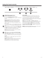 4
4
-
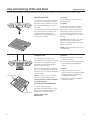 5
5
-
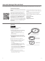 6
6
-
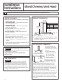 7
7
-
 8
8
-
 9
9
-
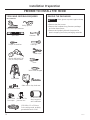 10
10
-
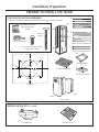 11
11
-
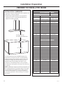 12
12
-
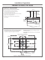 13
13
-
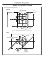 14
14
-
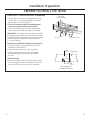 15
15
-
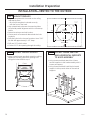 16
16
-
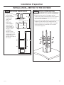 17
17
-
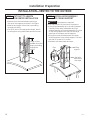 18
18
-
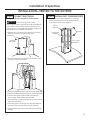 19
19
-
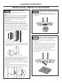 20
20
-
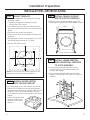 21
21
-
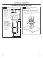 22
22
-
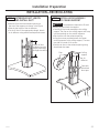 23
23
-
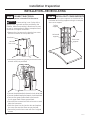 24
24
-
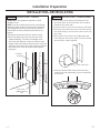 25
25
-
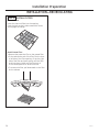 26
26
-
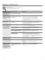 27
27
-
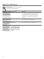 28
28
-
 29
29
-
 30
30
-
 31
31
-
 32
32
-
 33
33
-
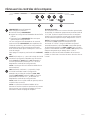 34
34
-
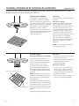 35
35
-
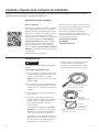 36
36
-
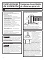 37
37
-
 38
38
-
 39
39
-
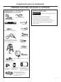 40
40
-
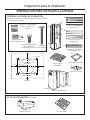 41
41
-
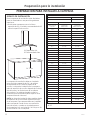 42
42
-
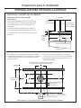 43
43
-
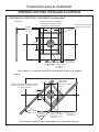 44
44
-
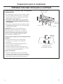 45
45
-
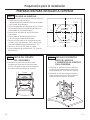 46
46
-
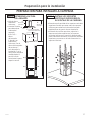 47
47
-
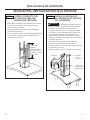 48
48
-
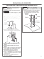 49
49
-
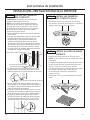 50
50
-
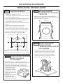 51
51
-
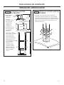 52
52
-
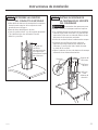 53
53
-
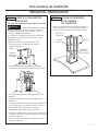 54
54
-
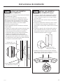 55
55
-
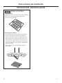 56
56
-
 57
57
-
 58
58
-
 59
59
-
 60
60


GE PV977N1SS El manual del propietario
- Categoría
- Campanas de cocina
- Tipo
- El manual del propietario
en otros idiomas
- English: GE PV977N1SS Owner's manual
Artículos relacionados
Otros documentos
-
GE Profile UVI7361SWSS El manual del propietario
-
-
-
Haier HCH6500ALS Installation and User Manual
-
Monogram ZV850SPSS Guía de instalación
-
 GE Monogram ZV850 DL 2ec018a52e3899a304151fc07370
-
-
ReVent RVS150 Guía de instalación
-
ReVent RVS80 Guía de instalación
