

ContentsContents
ContentsContents
Contents
What You Get ............................................................................................................................................1
Product Layout ..........................................................................................................................................2
Setting Up ..................................................................................................................................................5
Setting Up-Camera ...................................................................................................................................6
Setting Up-Receiver ..................................................................................................................................9
Setting Up-Other Application ............................................................................................................... 12
Orienting Units for Optimal Performance ........................................................................................... 13
Auto-Sequence Function for Multiple Location Monitoring ............................................................ 14
Troubleshooting ...................................................................................................................................... 16
Care and Maintenance ........................................................................................................................... 17
Specifications ........................................................................................................................................... 18
Declaration of Conformity .................................................................................................................... 18
FCC Statement ...................................................................................................................................... 18

What YWhat Y
What YWhat Y
What You Getou Get
ou Getou Get
ou Get
•One Camera
•One Receiver
•One Audio/Video Cable (RCA to RCA for NTSC; RCA to Scart for PAL)
•Two Power Adapters
•One Quick Installation Guide
•This User's Manual
Note: Two AC adapters with different length cables are included with this product. Use either depending
on distance from the wall outlet.
Receiver
English
1
Camera


Product LayoutProduct Layout
Product LayoutProduct Layout
Product Layout
Infrared LEDs
Eight LEDs to provide infrared light for night vision.
Lens
Focuses image automatically without any adjustment.
Lens Body
Rotates up to 180 degrees.
Microphone
2.4 GHz Audio/Video Antenna (Front )
Transmits audio/video signals. Caution: Antenna does not rotate freely through 360 degrees. (See "Orienting
Units for Optimal Performance", on page 13)
Channel Selection Switch
Select the channel by sliding the slide switch to the channel number you want.
Must select the same channel on both the camera and receiver.
Power Indicator LED
OFF/ON/NIGHT
POWER ON/POWER OFF and NIGHT VISION ON switch.
9V Power Adapter Plug
Mounting Hole
Battery Compartment
1
2
3
4
5
6
7
8
9
10
3
11


Product LayoutProduct Layout
Product LayoutProduct Layout
Product Layout
Power Indicator LED
The LED should be lit when the ON/OFF switch is in the ON position..
2.4GHz Audio/Video Antenna (Front )
Transmits and receives Audio/Video signals. Caution: Antenna does not rotate freely 360 degrees. (See
"Orienting Units for Optimal Performance", on page 13)
Channel Selection Dipswitches
Select the channel by setting the channel dipswitch to the ON position. The number 5 dipswitch
sets the timer for the auto-sequence function (see "Auto-Sequence Function for Multiple Location
Monitoring", on page 14).
Must select the same channel both on camera and receiver.
Left Audio Jack (White)
Right Audio Jack (Red)
Video Jack (Yellow)
9V Power Adapter Plug
ON/OFF Switch
1
2
3
4
5
6
7
8
5

Setting UpSetting Up
Setting UpSetting Up
Setting Up
Before you make the connection:
•Always make sure the unit ON/OFF switch is in the OFF position.
•Set the channel switches on the back of the camera and receiver to the same channel.
•If you wish to wall mount the camera, it is recommended that the receiver reception be
tested before fixing in place. Have one person hold the camera against the wall in the
selected mounting area while another checks reception on the TV. If interference or other
problems are present, refer to the Troubleshooting section on page 16 of this manual. You
may need to select a different location in the room for mounting the camera.
Receiver
Camera
6

Setting Up-CameraSetting Up-Camera
Setting Up-CameraSetting Up-Camera
Setting Up-Camera
Power SupplyPower Supply
Power SupplyPower Supply
Power Supply
1The camera uses either batteries (AA-size) or household AC current.
To Load Batteries
Open the battery compartment cover in the direction of the arrow.
Slide the POWER Switch to the ON position. The LED on the back of the camera should light.
Never mix old batteries with new ones.
Remove batteries from the camera if you do not plan to use it for a period of time.
Using AC Power
Plug one end of the provided power adapter into a wall outlet and the other end into the rear
of the camera. Note: Use the adapter with the longer cable to connect the camera if the
camera is mounted on a ceiling or wall at a long distance from the wall outlet.
Insert batteries so their plus (+) and minus (-) ends are
facing as shown in the illustration.
Close the battery compartment cover. Make sure the
battery compartment cover is locked securely.
7
1
2
3

Setting Up-CameraSetting Up-Camera
Setting Up-CameraSetting Up-Camera
Setting Up-Camera
2Changing the Lens OrientationChanging the Lens Orientation
Changing the Lens OrientationChanging the Lens Orientation
Changing the Lens Orientation
Place the camera in a convenient location, point the lens towards the observation area and adjust
the angle by rotating the lens body. The camera's auto focus feature automatically focuses the
image.
The camera's head rotates horizontally up to 200 degrees and vertically up to 30 degrees. The
lens is built into a lens body that is designed to rotate vertically up to 180 degrees, allowing the
camera to cover the widest angles.
3Fine TuningFine Tuning
Fine TuningFine Tuning
Fine Tuning
Adjust the antenna so that the front (curved side) faces the room where the receiver is to be set
up. See "Orienting Units for Optimal Performance", on page 13.
Do not apply excessive force when rotating.
Doing so can cause serious damage to the camera.
Rotates up to 90
towards the back
Rotates up to 90
towards the front
8

Setting Up-ReceiverSetting Up-Receiver
Setting Up-ReceiverSetting Up-Receiver
Setting Up-Receiver
Connect one set of audio/video cables to the audio/video jacks of the receiver, matching
the plug colors with the jacks on the receiver.
Connect the other end of the cable to the audio/video jacks on the TV labeled LINE IN,
matching the plug colors with the jacks on the TV. Some connection scenarios are shown
on the next page.
Note: For PAL systems, the connector on the audio/video component is a Scart socket.
Connect the Scart connector labeled RECEIVER to the Scart socket labeled IN on the
audio/video component; connect the RCA connector to the receiver.
11
11
1Connecting the Receiver to a TVConnecting the Receiver to a TV
Connecting the Receiver to a TVConnecting the Receiver to a TV
Connecting the Receiver to a TV
Receiver
Audio/Video
Component
RCA to Scart Cable
Receiver
9
1
2

Setting Up-ReceiverSetting Up-Receiver
Setting Up-ReceiverSetting Up-Receiver
Setting Up-Receiver
Connecting to a TV With an Audio/Video Component
Receiver
Connecting to a TV Without Audio/Video IN Jacks
If your TV has UHF/VHF input only, and there is no audio/video
equipment near your TV, you will need to get an RF-Modulator
(available at your local electronic store) to convert the RCA jacks to
coax. Then select either channel 3 or 4 on your TV to view the video.
Note:
If the TV has only one input
for audio (mono sound
only), connect the white
plug to that single audio
input and to the receiver's
AUDIO LEFT jack.
If the jacks on the TV are
colored differently, connect
the yellow plug to the jack
labeled Video, the red plug
to the jack labeled AUDIO
RIGHT, and the white plug
to the jack labeled AUDIO
LEFT.
VIDEO AUDIO
RF OUT
TV
RF Modulator
CH 3/4 VHF/UHF
TV
VIDEO AUDIO IN
Receiver
10

Plug one end of the provided power adapter into a wall outlet and the other end into the rear of
the receiver.
Turn the ON/OFF switch to the ON position. The LED on the front of the unit should light.
Place the receiver in a convenient location, then adjust its antenna so that the front (curved face)
faces the room where the camera is set up. See "Orienting Units for Optimal Performance", on
page 13.
Connecting to a TV With an Audio/Video Component
Setting Up-ReceiverSetting Up-Receiver
Setting Up-ReceiverSetting Up-Receiver
Setting Up-Receiver
2
3
Receiver
VIDEO AUDIO
RF OUT
TV
Audio/Video
Component
VHF/UHF
Power SupplyPower Supply
Power SupplyPower Supply
Power Supply
Fine TuningFine Tuning
Fine TuningFine Tuning
Fine Tuning
11

Setting Up-Other ApplicationSetting Up-Other Application
Setting Up-Other ApplicationSetting Up-Other Application
Setting Up-Other Application
Receiving on a ComputerReceiving on a Computer
Receiving on a ComputerReceiving on a Computer
Receiving on a Computer
•Connect the yellow video plug of the audio/video cable to the video jack on the TV tuner device or
video capture card, and to the video jack of the receiver.
•Connect the mini stereo plug of the adapter (available in any electronic store) into the AUDIO IN
jack on the back of computer, and the red and white audio/video plugs into the AUDIO LEFT and
AUDIO RIGHT jacks on the receiver.
Night VisionNight Vision
Night VisionNight Vision
Night Vision
The camera has eight high-intensity LEDs for picking up clear images in unlit locations. To turn on the
night vision function, slide the switch as shown in the illustration on the right.
Note: Turning the night vision function
off when not required will save power.
12

Orienting Units for Optimal PerformanceOrienting Units for Optimal Performance
Orienting Units for Optimal PerformanceOrienting Units for Optimal Performance
Orienting Units for Optimal Performance
Placing:Placing:
Placing:Placing:
Placing:
Place the camera and receiver on a flat, stable surface to prevent damage from falling.
For optimal performance, try to place the units as high as possible to avoid any possible interference
from people walking between the camera and the receiver.
Microwave ovens can cause interference. Be sure you do not position the camera and receiver with a
microwave in the path between them.
Adjusting the Audio/Video AntennasAdjusting the Audio/Video Antennas
Adjusting the Audio/Video AntennasAdjusting the Audio/Video Antennas
Adjusting the Audio/Video Antennas
For optimal reception, the antennas on both camera and receiver
should be oriented. In most situations the curved face of the
audio/video antennas on both the transmitter and receiver
should be facing each other. If the camera and receiver are less
than 10 feet (3 meters) apart, keep the audio/video antennas flat
in their casings.
13
The audio/video antennas have been designed to pivot but have limited
rotation in either clockwise or counterclockwise directions. Antenna does
not rotate freely 360 degrees. Rotating past the point where resistance is felt
will result in permanent damage to both antenna and mechanical stopper.

Auto-Sequence Function for Multiple Location MonitoringAuto-Sequence Function for Multiple Location Monitoring
Auto-Sequence Function for Multiple Location MonitoringAuto-Sequence Function for Multiple Location Monitoring
Auto-Sequence Function for Multiple Location Monitoring
The receiver's built in auto-sequence function is ideal for security use. The receiver can be used with up
to four wireless cameras on four different channels and display them in sequence on a single TV/
monitor. The receiver's various operating modes are set via dipswitches as shown in the following
diagram:
Dipswitches 1 ~ 4: Set up the automatic channel sequence function
Slide the channel dipswitch that you wish to view to the ON position.
Diswitch 5: Sets the sequence change interval time
ON: Changes channel every eight seconds.
OFF: Changes channel every four seconds.
Factory-Preset Mode
14

Auto-Sequence Function for Multiple Location MonitoringAuto-Sequence Function for Multiple Location Monitoring
Auto-Sequence Function for Multiple Location MonitoringAuto-Sequence Function for Multiple Location Monitoring
Auto-Sequence Function for Multiple Location Monitoring
Note 1: The receiver will auto detect the receiving channels, and display them in sequence. When
only one channel dip switch is in the ON position, the receiver will receive the channel
continuously, without regard to the position of the 5th dip switch. If more than one dip
switch remains on, the auto-sequence function will continue on those channels.
Note 2: When none of the dip switches are in the ON position, the receiver will automatically set the
receiving channel to Channel 1.
Example:
Using the auto-sequence function:
If you have two wireless camera and their channels are set on
CHANNEL 1 and CHANNEL 3, and you wish to monitor the
two channels in sequence, you must slide up the first and third
dip switches to the ON position (see the diagram on the right).
If you wish these two channels to be alternated at eight-second
intervals, slide the DIP 5 switch to the ON position. Leave it in the
lower position for four-second channel change intervals.
15
Stopping the auto-sequence function:
To stop the auto-sequence function and lock on one channel, leave
the dip switch for the channel you want to receive in the ON
position. Slide the others to the lower position.

TroubleshootingTroubleshooting
TroubleshootingTroubleshooting
Troubleshooting
If you are not getting any signal at allIf you are not getting any signal at all
If you are not getting any signal at allIf you are not getting any signal at all
If you are not getting any signal at all
•Check that the receiver is properly connected to the TV which you want to receive the signal
•Check the power ON/OFF switches on the camera and receiver
•Check power switches on the TV
•Make sure power plugs are pushed all the way in.
•Check all cable connections.
•Check the CHANNEL switch on both camera and receiver are set to the same number
•If you connect the receiver to a TV through an RF modulator, check that the TV is tuned to the
same channel as the TV Channel switch on the RF modulator (3 or 4)
If the signal is poor, or there is interferenceIf the signal is poor, or there is interference
If the signal is poor, or there is interferenceIf the signal is poor, or there is interference
If the signal is poor, or there is interference
•Adjust the antennas orientation (see "Orienting Units for Optimal Performance", on page 15)
•Change the channel on both camera and receiver and make them the same.
•If there is a microwave oven in use in the path between the camera and receiver, remove the
microwave oven or turn it off
•Make sure the camera and receiver are within range (up to 300 feet)
•Check the channel dipswitch positions on the receiver
16

Care and MaintenanceCare and Maintenance
Care and MaintenanceCare and Maintenance
Care and Maintenance
•For best performance, don't touch the antennas unnecessarily
•Keep all its parts and accessories out of young children's reach
•Camera performances can be adversely affected by fingerprints or dirt on the lens surface. Avoid
touching the lens surface with your fingers.
•Should the lens become dirty, use a blower to blow off dirt and dust, or a soft, dry cloth to wipe off
the lens.
•Keep dry. Precipitation, humidity, and liquids, contain minerals that will corrode electronic circuits
•Do not use or store in dusty, dirty areas. Moving parts may be damaged
•Do not store in hot areas. High temperatures can shorten the life of electronic devices and warp or
melt certain plastics
•Do not store in very cold areas. When the Wireless Camera System warms up (to its normal
temperature), moisture can form inside the case, which may damage electronic circuit boards
•Do not attempt to open the case. Non-expert handling of the device may damage it
•Do not drop , knock, or shake it. Rough handling can break internal circuit boards
•Do not use harsh chemicals, cleaning solvents, or strong detergents when cleaning. Wipe with a
soft cloth slightly dampened in a mild soap-and-water solution
•If the Wireless Camera System is not working properly, take it to your nearest qualified service
facility. The personnel there will assist you, and if necessary, arrange for service
•Operate this product using only the power supply included with it or provided as an accessory
•Do not overload electrical outlets or extension cords as this can result in fire or electric shock
17

18
FCC StatementFCC Statement
FCC StatementFCC Statement
FCC Statement
This equipment has been tested and found to comply with the limits for a Class B digital device, pursuant to Part 15 of the FCC Rules. These limits are
designed to provide reasonable protection against harmful interference in a residential installation. This equipment generates, uses and can radiate radio
frequency energy and, if not installed and used in accordance with the instructions, may cause harmful interference to radio communications. However,
there is no guarantee that interference will not occur in a particular installation. If this equipment does cause harmful interference to radio or television
reception, which can be determined by turning the equipment off and on, the user is encouraged to try to correct the interference by one or more of the
following measures:
•Reorient or relocate the receiving antenna
•Increase the separation between the equipment and receiver
•Connect the equipment into an outlet on a circuit different from that to which the receiver is connected
•Consult the dealer or an experienced radio/TV technician for help
FCC Label Compliance Statement:
This device complies with Part 15 of the FCC Rules. Operation is subject to the following two conditions: (1) this device may not cause harmful
interference, and (2) this device must accept any interference received, including interference that may cause undesired operation.
Frequency 2.4~2.4835 GHz 2.4~2.4835 GHz
Range 300 feet (100 meters) clear line of sight 300 feet (100 meters) clear line of sight
Antennas Directional circular-polarized antenna Directional circular-polarized antenna
Channel 4 selectable channels 4 selectable channels
AV mod/demod. method FM FM
Image Sensor -- 1/4” CMOS image sensor
Lens -- f 3.6, F 2.0
Audio Stereo audio input and output --
Video Composite video input and output --
Dimensions 14 x 11 x 2.8 cm (5.5 x 4.3 x 1.1 in) 10 x 9 x 15 (3.9 x 3.5x5.9 in)
Weight 200g (7.1 ounces) 300 g (10.6 ounces) without batteries
Operating remperature 10°C~50°C (14° F~122° F) 10°C~50°C (14° F~122° F)
SpecificationsSpecifications
SpecificationsSpecifications
Specifications
Receiver Camera
Specifications are subject to change without notice.
Declaration of ConformityDeclaration of Conformity
Declaration of ConformityDeclaration of Conformity
Declaration of Conformity
Hereby, TRANWO TECHNOLOGY CORP., declares that this GigaAir 3010 is in compliance with the essential requirements and other relevant provisions
of Directive 1999/5/EC.

Contenu de l’emballageContenu de l’emballage
Contenu de l’emballageContenu de l’emballage
Contenu de l’emballage
•Une Caméra
•Un Récepteur
•Un câble Audio/Vidéo (câble RCA vers RCA pour NTSC; câble RCA vers Scart pour PAL)
•Deux adaptateurs
•Un guide d’installation rapide
•Manuel de l’utilisateur
Note: Deux adaptateurs AC avec des câbles de taille différente sont inclus avec ce produit. Utilisez l’un
ou l’autre selon la distance qu’il y a jusqu’à la prise de courant murale.
SommaireSommaire
SommaireSommaire
Sommaire
Illustrations ................................................................................................................................................ 2
Configuration de la Caméra .....................................................................................................................6
Configuration du Récepteur .....................................................................................................................8
Configuration des autres Applications .................................................................................................. 11
Orientation des Unités pour une performance maximum .................................................................. 12
Fonction séquence automatique pour la surveillance de multiple locations ....................................... 13
Dépannage .............................................................................................................................................. 14
Français
1


IllustrationsIllustrations
IllustrationsIllustrations
Illustrations
LED Infrarouges
Huit LED infrarouges fournissent une lumière infrarouge pour la vision de nuit.
Objectif
Mis au point automatique de l’image sans aucun ajustement.
Corps de l’objectif
Peut effectuer une rotation de 180 degrés.
Microphone
Antenne (Face) Audio/Vidéo 2.4 GHz
Permet la transmission des signaux audio/vidéo.
Attention: Les antennes ne peuvent pas tourner à 360 degrés. (Voir "Orientation des unités pour une
performance optimale", page 12)
Bouton de sélection des canaux
Sélectionnez le canal en tournant le bouton vers le numéro du canal que vous désirez configurer.
Vous devez choisir le même canal sur la caméra et sur le récepteur.
LED Indicateur d’Alimentation
Eteint/Allumé/Nuit (ON/OFF/NIGHT)
Bouton pour la Mise sous tension/Hors tension et la Vision de Nuit.
Prise de l’Adaptateur secteur 9V
Emplacement du montant
Compartiment des piles
1
2
3
4
5
6
7
9
3
8
10
11
10
11


IllustrationsIllustrations
IllustrationsIllustrations
Illustrations
LED indicateur d’alimentation
Lorsque le bouton Allumé/Eteint de l’alimentation est sur la position Allumé, le LED doit alors
s’allumer.
Antenne Audio/Vidéo 2.4GHz (Face )
Permet la transmission des signaux Audio/Vidéo. Attention: l’antenne ne peut pas se tourner à 360
degrés. (Voir "Orientation des unités pour une performance optimale", page 12)
Commutateur de sélection des canaux
Sélectionnez le canal en relevant le commutateur vers la position Allumé. Le commutateur numéro
5 configure le minuteur pour la fonction d’auto-séquence (voir "Fonction d’auto-séquence pour
la surveillance de multiple locations", page 13 ).
Vous devez sélectionner le même canal pour le caméra et le récepteur.
Prise Audio gauche (Blanche)
Prise Audio droite (Rouge)
Prise vidéo (Jaune)
Adaptateur secteur 9V
Bouton Allumé/Eteint (ON/OFF)
1
2
3
4
7
8
5
6
5

AlimentationAlimentation
AlimentationAlimentation
Alimentation
Cet appareil photo possède deux types d’alimentation. Vous pouvez choisir entre l’utilisation des
piles (Alcaline de type AA) ou l’utilisation du secteur.
1
Insérer les piles
Ouvrez le portillon du compartiment des piles dans le sens de la flèche.
Ne mélangez jamais des piles usagées et des piles neuves.
Retirez les piles de la caméra si vous ne comptez pas
vous en servir pendant une longue période.
Utilisation de l’alimentation AC
Branchez l’une des extrémités de l’adaptateur secteur fourni dans la prise de courant murale
et l’autre extrémité à l’arrière de la caméra. Note: Utilisez l’adaptateur avec le plus long câble
pour connecter la caméra, si celle-ci est fixé à un mur ou un plafond et qu’elle est très
éloignée de la prise de courant murale.
Insérez les piles de manière à ce que le signe plus (+) et le signe moins (-) soient
placer comme le montre l’illustration.
ConfigurationConfiguration
ConfigurationConfiguration
Configuration
Si vous désirez fixer la caméra sur un mur, il est recommendé de tester d’abord la réception du
récepteur, avant de fixer la caméra. Une personne peut tenir la caméra à l’emplacement où elle
doit être fixée, pendant qu’une autre personne vérifie la réception sur la télévision. Si il y a des
interférences ou d’autres problèmes, il sera peut-être nécessaire de choisir un autre emplacement
pour fixer la caméra.
6
Refermez le portillon du compartiment des piles. Assurez-
vous que le portillon est correctement refermé.
1
2
3

ConfigurationConfiguration
ConfigurationConfiguration
Configuration
Placez le bouton d’ALIMENTATION sur la position Allumé. Le LED à l’arrière de la caméra
doit alors s’allumer.
2Changer l’orientation de l’objectifChanger l’orientation de l’objectif
Changer l’orientation de l’objectifChanger l’orientation de l’objectif
Changer l’orientation de l’objectif
Placez la caméra dans un emplacement adéquate, pointez l’objectif vers l’endroit à observer et
ajustez l’angle en tournant le corps de l’objectif. L’auto-focus intégré de la caméra, permet la
mise au point automatique de l’image.
La tête de la caméra peut tourner horizontalement jusqu’à 200 degrés, et verticalement jusqu’à
30 degrés. L’objectif a été réalisé dans un corps qui peut tourner verticalement jusqu’à 180
degrés, ce qui permet à la caméra de couvrir les plus grands angles.
3OptimisationOptimisation
OptimisationOptimisation
Optimisation
Ajustez l’antenne de manière à ce que sa partie concave soit en face de la pièce où se trouve le
récepteur. (Voir "Orientation des unités pour une performance optimale”, page 12.
Ne forcez pas lorsque
vous tourner.
7
Rotation jusqu’à 90
degrés vers l’arrière
Rotation jusqu’à 90
degrés vers l’avant

ConfigurationConfiguration
ConfigurationConfiguration
Configuration
8
Connectez une paire de câbles audio/vidéo aux prises audio/vidéo du récepteur, en faisant
correspondre les couleurs des fiches avec les couleurs des prises du récepteur.
Connectez l’autre extrémité du câble dans les prises audio/vidéo libellées Entrée sur la télévision,
en faisant correspondre les couleurs des fiches avec les couleurs des prises de la télévision. Des
schémas de connexion sont sur la page suivante.
Note: Pour les systèmes PAL, le connecteur audio/vidéo est un connecteur de tupe Scart.
Connectez le connecteur Scart libellé RECEPTEUR au connecteur Scart libellé Entrée sur
le composant audio/vidéo, puis connectez le connecteur RCA au récepteur.
11
11
1
Receiver
Audio/Video
Component
RCA to Scart Cable
Receiver
Connexion du récepteur à une télévisionConnexion du récepteur à une télévision
Connexion du récepteur à une télévisionConnexion du récepteur à une télévision
Connexion du récepteur à une télévision
1
2

ConfigurationConfiguration
ConfigurationConfiguration
Configuration
9
Connexion à une télévision qui possède un composant
audio/Vidéo
Récepteur
Connexion à une télévision qui ne possède pas d’Entrées
Audio/Vidéo
Si votre télévision ne possède qu’une entrée UHF/VHF, et qu’il n’y a pas
d’équipement audio/vidéo proche de votre télévision, vous devez vous procurer
un modulateur RF (disponible chez votre marchand de composants
éléctroniques) afin de convertir la prise RCA en prise coaxiale. Sélectionnez
alors le canal 3 ou 4 sur votre télévision pour voir la vidéo.
Note:
Si votre télévision ne
possède qu’une entrée
audio (son mono
seulement), connectez la
fiche blanche à cette
entrée audio et à la prise
AUDIO GAUCHE du
récepteur.
Si les prises de la télévision
sont de couleurs
différentes, connectez la
fiche jaune à la prise
libellée Vidéo, la fiche
rouge à la prise libellée
AUDIO DROITE, et la
fiche blanche à la prise
libellée AUDIO
GAUCHE.
VIDÉO AUDIO Sortie RF
TV
Canal 3/4 VHF/UHF
TV
VIDÉO AUDIO Entrée
Récepteur
Modulateur RF

Branchez l’une des extrémités de l’adaptateur secteur fourni dans la prise de courant murale et
l’autre extrémité à l’arrière du récepteur.
Placez le bouton Allumé/Eteint sur la position Allumé. Le LED sur le devant de l’unité doit
s’allumer.
Placez la caméra dans un endroit adéquate, puis ajustez l’antenne de manière à ce que la partie
concave soit en face de la pièce où se trouve le caméra (Voir “Orientation des unités pour une
performance optimale”, page 12.
Connexion à une télévision qui possède un composant Audio/Vidéo
ConfigurationConfiguration
ConfigurationConfiguration
Configuration
2
3
Récepteur
VIDÉO AUDIO
Sortie RF
TV
Composant
Audio/Vidéo
VHF/UHF
AlimentationAlimentation
AlimentationAlimentation
Alimentation
OptimisationOptimisation
OptimisationOptimisation
Optimisation
10

ConfigurationConfiguration
ConfigurationConfiguration
Configuration
Réception sur un ordinateurRéception sur un ordinateur
Réception sur un ordinateurRéception sur un ordinateur
Réception sur un ordinateur
• Connectez la fiche vidéo jaune du câble audio/vidéo à la prise vidéo de votre tuneur de télévision ou
de votre carte de capture vidéo, ainsi qu’à la prise vidéo du récepteur.
• Connectez la mini fiche stéréo de l’adaptateur (disponible dans les magasins d’électroniques) à la
prise Entrée Audio à l’arrière de l’ordinateur, ainsi que les fiches audio/vidéo rouge et blanche dans
les prises AUDIO GAUCHE et AUDIO DROITE du récepteur.
Vision de NuitVision de Nuit
Vision de NuitVision de Nuit
Vision de Nuit
La caméra est équipée de huit LED de haute intensité pour recueillir des images claires d’endroits non-
éclairés.Afin d’activer la fonction Vision de nuit, placez le bouton comme il est indiqué dans l’illustration
de droite.
Note: En désactivant la fonction Vision de
Nuit lorsqu’elle n’est pas requise, vous
économiserez de l’énergie.
11

Orientation des unités pour une performance optimaleOrientation des unités pour une performance optimale
Orientation des unités pour une performance optimaleOrientation des unités pour une performance optimale
Orientation des unités pour une performance optimale
Emplacement:Emplacement:
Emplacement:Emplacement:
Emplacement:
Placez le caméra et le récepteur sur une surface plate et stable afin d’éviter qu’ils ne tombent.
Pour une meilleure performance, essayez de placer les unités le plus haut possible, afin d’éviter les
interférences provoquées par des personnes qui se déplaceraient entre le caméra et le récepteur.
Les fours à micro-ondes peuvent causer des interférences. Assurez-vous de ne pas placer le caméra et le
récepteur avec un four à micro-ondes entre les deux.
Ajuster les antennes audio/vidéoAjuster les antennes audio/vidéo
Ajuster les antennes audio/vidéoAjuster les antennes audio/vidéo
Ajuster les antennes audio/vidéo
Pour une meilleure réception, les antennes du transmetteur et du récepteur doivent être orientées
correctement. Dans la plupart des cas, la surface concave des antennes du
caméra et du récepteur doivent se faire face. Si le caméra et le
récepteur sont à une distance de moins de 3 mètres, laissez les
antennes audio/vidéo repliées.
12
Les antennes audio/vidéo ont été réalisées pour pivoter,
mais leur rotation, dans le sens des aiguilles d’une montre
ou dans le sens inverse, est limitée. Les antennes ne peuvent
pas tourner à 360 degrés. Si vous continuez de tourner les antennes
alors que vous sentez une résistance, vous risquez de causer des dommages
permanent à l’antenne et à l’arrêt mécanique.

Fonction Auto-Séquence pour la surveillance de multiple locationsFonction Auto-Séquence pour la surveillance de multiple locations
Fonction Auto-Séquence pour la surveillance de multiple locationsFonction Auto-Séquence pour la surveillance de multiple locations
Fonction Auto-Séquence pour la surveillance de multiple locations
Note 1: Le récepteur détecte automatiquement les cannaux de réception, et les affiche en séquence.
Lorsqu’un seul commutateur est en position Allumé, le récepteur reçoit le canal en continu,
quelque soit la position du commutateur 5. Si plus d’un commutateur est sur la position
Allumé, la fonction d’auto-séquence continue sur ces canaux.
Note 2: Lorsque aucun commutateur n’est dans la position Allumé, le récepteur configure
automatiquement le canal 1 comme canal de réception.
Le récepteur possède une fonction d’auto-séquence idéale pour la sécurité. Le récepteur peut être utilisé
avec quatre caméras sur quatre canaux différents et les afficher en séquence sur une seule télévision ou
un seul moniteur. Les différents modes d’opération du récepteur sont configurés avec les commutateurs
comme le montre le diagramme:
Commutateur 1 ~ 4 (DIP 1~4): Configure la fonction automatique des canaux
Relevez le commutateur du canal que vous désirez voir, vers la position Allumé.
Commutateur 5 (DIP 5): Configure l’interval de temps du changement de séquence
Allumé (ON): Change le canal toutes les huit secondes.
Eteint (OFF): Change le canal toutes les quatres secondes.
13
Mode Configuration d’origine

DépannageDépannage
DépannageDépannage
Dépannage
Si vous ne recevez aucun signal du toutSi vous ne recevez aucun signal du tout
Si vous ne recevez aucun signal du toutSi vous ne recevez aucun signal du tout
Si vous ne recevez aucun signal du tout
• Assurez-vous que le connecteur est correctement connecté à la télévision qui doit recevoir le signal.
• Vérifiez les boutons d’alimentation Allumé/Eteint sur la caméra et sur le récepteur.
• Vérifiez le bouton d’alimentation de la télévision
• Assurez-vous que les fiches sont poussées jusqu’au fond.
• Vérifiez toutes les connexions des câbles.
• Assurez-vous que le bouton du CANAL soit sur le même numéro de canal sur la caméra et sur le
récepteur
• Si vous avez connecté le récepteur à une télévision avec un modulateur RF, Vérifiez que la télévision
est configurée sur le même canal que le canal de la télévision du modulateur RF (3 ou 4)
Si le signal est faible ou s’il y a des interférencesSi le signal est faible ou s’il y a des interférences
Si le signal est faible ou s’il y a des interférencesSi le signal est faible ou s’il y a des interférences
Si le signal est faible ou s’il y a des interférences
• Ajustez l’orientation des antennes (voir “Orientation des unités pour une performance optimale”
page 12).
• Changez le canal de la caméra et du récepteur et assurez-vous que ce soit le même sur les deux.
• Si il y a un four à micro-ondes entre la caméra et le récepteur, enlevez-le ou éteignez-le.
• Assurez-vous que la distance entre la caméra et le récepteur ne dépasse pas les 90 mètres.
• Vérifiez les positions des commutateurs des canaux sur le récepteur.
14

Lista de Artículos IncluídosLista de Artículos Incluídos
Lista de Artículos IncluídosLista de Artículos Incluídos
Lista de Artículos Incluídos
• Una Cámara
• Un Receptor
• Un Cable para Audio/Vídeo (cable RCA a RCA para NTSC; cable RCA a Scart para PAL)
• Dos Adaptadores de Corriente
• Una Guía de Instalación Rápida
• Este Manual del Usuario
Nota: Dos adaptadores de corriente AC con cables de diferente longitud son incluídos con el
producto. Use cualquiera, dependiendo de la distancia desde la ficha de corriente en la pared.
ContenidosContenidos
ContenidosContenidos
Contenidos
Diseñno del Producto ........................................................................................................... .....................2
Instalar la Cámara ......................................................................................................................................6
Instalar el Receptor .................................................................................................................................... 8
Instalar otras Aplicaciones ...................................................................................................................... 11
Orientar Inidades para su Optimo Funcionamiento ............................................................................ 12
Función de Auto-Secuencia para Monitoreo de Localización Múltiple ............................................. 13
TResolviendo Problemasroubleshooting ............................................................................................... 14
Español
1


Diseño del ProductoDiseño del Producto
Diseño del ProductoDiseño del Producto
Diseño del Producto
LEDs Infrarrojos
Ocho LEDs para proveer de luz infrarroja para visión nocturna.
Objetivo
Focaliza la imagen automáticamente sin ningún ajuste.
Cuerpo del Objetivo
Rota hasta 180 grados.
Micrófono
Antena Audio/Vídeo 2.4 GHz (Frontal)
Transmite señales de audio/vídeo. Precaución: La antena no rota libremente en 360 grados. (Vea "Orientar
Unidades para su Optimo Funcionamiento", en página 12)
Selector de Canal
Seleccione el canal al correr la tecla deslizadora hasta el número de canal que quiere.
Debe seleccionar en mismo canal para la cámara y el receptor.
LED Indicador de Corriente
APAGADO/ENCENDIDO/NOCTURNO (ON/OFF/NIGHT)
Tecla ENCENDIDO/APAGADO y ENCENDIDO VISION NOCTURNA.
Enchufe Adaptador de Corriente 9V
Orificio para Montaje
Compartimento para Baterías
1
6
8
9
3
2
3
4
5
11
10
7


Product LayoutProduct Layout
Product LayoutProduct Layout
Product Layout
LED Indicador de Corriente
El LED debe estar iluminado cuando la tecla ENCENDIDO/APAGADO está en posición de
encendido.
Antena 2.4GHz Audio/Vídeo (Frente)
Transmite y recibe señales de Audio/Vídeo. Precaución: La antena no rota libremente en 360 grados.
(Vea "Orientar Unidades para su Optimo Funcionamiento", en página 12)
Teclas Selector de Canal
Seleccione el canal al definir la tecla Selector de Canal en posición ENCENDIDO. La tecla
número 5 define el temporizador para la función de auto-secuencia (vea "Función Auto-
Secuencia para Monitoreo de Localización Múltiple", en página 13).
Debe seleccionar el mismo canal para el cámara y el receptor.
Clavija de Audio Izquierda (Blanca)
Clavija de Audio Derecha (Roja)
Clavija de Video (Amarilla)
Enchufe Adaptador de Corriente 9V
Tecla ENCENDIDO/APAGADO(ON/OFF)
1
2
3
4
5
6
7
8
5

Fuente de EnergíaFuente de Energía
Fuente de EnergíaFuente de Energía
Fuente de Energía
1La cámara usa baterías (tamaño-AA) o corriente AC en su casa.
Cargar las Baterías
Abra la tapa del compartimento de baterías en la dirección indicada por la flecha.
Nunca mezcle baterías viejas con baterías nuevas.
Remueva las baterías de la cámara si no planea usarla por un período de tiempo.
Usar Corriente AC
Enchufe un extremo del adaptador de corriente en la ficha de la pared y el otro extremo en la
parte posterior de la cámara. Nota: Use el adaptador con el cable más largo para conectar la
cámara si la misma está montada en el techo o en la pared lejos de la ficha de corriente en el muro.
Inserte las baterías de manera que los extremos más (+) y
menos (-) estén de frente como muestra la ilustración.
InstalaciónInstalación
InstalaciónInstalación
Instalación
Si desea montar la cámara en la pared, se recomienda que la recepción del receptor sea probada
antes de fijar la ubicación. Solicite a una persona que sostenga la cámara contra la pared en el área
seleccionada para montaje mientras que otra persona verifica la recepción en el TV. Si se
presentan problemas de interferencia u otros, deberá seleccionar una ubicación diferente para
montar la cámara.
6
Cierre la tapa del compartimento de baterías. Asegúrese
de que la tapa del compartimento de baterías está cerrada
correctamente.
1
2
3

InstalaciónInstalación
InstalaciónInstalación
Instalación
Coloque la tecla ENCENDIDO/APAGADO en posición de encendido. El LED en la parte
posterior de la cámara se iluminará.
Cambiar la Orientación del ObjetivoCambiar la Orientación del Objetivo
Cambiar la Orientación del ObjetivoCambiar la Orientación del Objetivo
Cambiar la Orientación del Objetivo
Ubique la cámara en un lugar conveniente, apunte el objetivo hacia el área de observación y
ajuste el ángulo al rotar el cuerpo del objetivo. La característica de auto foco de la cámara
automáticamente enfocará la imagen.
La cabeza de la cámara rota horizontalmente hasta 200 grados y verticalmente hasta 30 grados. El
objetivo está incorporado en el cuerpo del objetivo que está diseñado para rotar verticalmente
hasta 180 grados, permitiéndole a la cámara cubrir los ángulos más amplios.
3Sintonía FinaSintonía Fina
Sintonía FinaSintonía Fina
Sintonía Fina
Ajuste la antena de manera que el frente (lado curvo) se dirige hacia el lugar donde el receptor será
instalado. Vea "Orientar Unidades para su Optimo Funcionamiento", en página 12.
No fuerce
excesivamente al rotar.
7
Rota hasta 90
grados hacia atrás
Rota hasta 90 grados
hacia adelante
2

InstalaciónInstalación
InstalaciónInstalación
Instalación
Conecte un conjunto de cables de audio/vídeo a las clavijas de audio/vídeo del receptor,
coincidiendo el color de los enchufes con el color de las clavijas en el receptor.
Conecte el otro extremo del cable a las clavijas de audio/vídeo en el TV rotuladas ENTRADA
DE LINEA, coincidiendo el color de los enchufes con el color de las clavijas en el TV.
Algunas conexiones son mostradas en la página siguiente.
Nota: Para sistemas PAL, el conector en el componente de audio/vídeo es un enchufe Scart.
Conecte el conector Scart rotulado RECEPTOR al enchufe Scart rotulado INGRESO en el
componente de audio/vídeo; conecte el conector RCA al receptor.
11
11
1Conectar el Receptor al TVConectar el Receptor al TV
Conectar el Receptor al TVConectar el Receptor al TV
Conectar el Receptor al TV
Receptor
Componente de Audio/Vídeo
Cable RCA a Scart
Receptor
8
2
1

InstalaciónInstalación
InstalaciónInstalación
Instalación
Conectar a un TV con Componente de Audio/Vídeo
Receptor
Conectar a un TV sin clavijas de Entrada de Audio/Vídeo
Si el TV tiene sólo ingreso de UHF/VHF, y no hay un equipo de audio/
vídeo próximo a su TV, necesitará un Modulador-RF (disponible en
Tiendas de electrónica) para convertir las clavijas RCA a coaxil. Luego
seleccione canal 3 o canal 4 en su TV para ver el vídeo.
Nota:
Si el TV tiene sólo clavija de
ingreso para audio (sólo
mono sonido), conecte el
enchufe blanco al ingreso de
audio simple y a la clavija
AUDIO IZQUIERDA del
receptor.
Si las clavijas en el TV están
coloreadas de manera
diferente, conecte el enchufe
amarillo a la clavija rotulada
Vídeo, el enchufe rojo a la
clavija rotulada AUDIO
DERECHA, y el enchufe
blanco a la clavija rotulada
AUDIO IZQUIERDA.
VÍDEO AUDIO
SALIDA RF
TV
CH 3/4 VHF/UHF
TVTV
TVTV
TV
VÍDEO AUDIO IN
Receptor
9
Modulador RF

Enchufe un extremo del adaptador de corriente en la ficha de corriente de la pared y el otro
extremo en la parte posterior del receptor.
Coloque la tecla ENCENDIDO/APAGADO en posición de encendido. El LED en el frente de
la unidad se iluminará.
Coloque el receptor en una ubicación conveniente, luego ajuste su antena de manera que el
frente (faz curva) se dirija hacia el lugar donde está instalado el cámara. Vea "Orientar Unidades
para su Optimo Funcionamiento", en página 12.
Conectar a un TV con Componente de Audio/Vídeo
InstalaciónInstalación
InstalaciónInstalación
Instalación
2
3
Receptor
VÍDEO AUDIO
SALIDA RF
TV
Componente
de Audio/Vídeo
VHF/UHF
Fuente de EnergíaFuente de Energía
Fuente de EnergíaFuente de Energía
Fuente de Energía
Sintonía FinaSintonía Fina
Sintonía FinaSintonía Fina
Sintonía Fina
10

InstalaciónInstalación
InstalaciónInstalación
Instalación
Recibiendo en una ComputadoraRecibiendo en una Computadora
Recibiendo en una ComputadoraRecibiendo en una Computadora
Recibiendo en una Computadora
lConecte el enchufe de vídeo amarillo del cable de audio/vídeo a la clavija de vídeo en el dispositivo del
sintonizador de TV o de la tarjeta para captura de vídeo, y a la clavija de vídeo del receptor.
lConecte el enchufe del mini estéreo del adaptador (disponible en Tiendas de electrónica) en la clavija
ENTRADA DE AUDIO en la parte posterior de la computadora, y los enchufes rojo y blanco de
audio/vídeo en las clavijas AUDIO IZQUIERDA y AUDIO DERECHA en el receptor.
Visión NocturnaVisión Nocturna
Visión NocturnaVisión Nocturna
Visión Nocturna
La cámara tiene ocho LEDs de alta intensidad para recoger imágenes claras en lugares con poca iluminación.
Para encender la función de visión nocturna, deslice la tecla como se muestra en la ilustración de la
derecha.
Nota: Apague la función de visión
nocturna cuando no la use, para ahorrar
energía.
11

Orientar Unidades para su Optimo FuncionamientoOrientar Unidades para su Optimo Funcionamiento
Orientar Unidades para su Optimo FuncionamientoOrientar Unidades para su Optimo Funcionamiento
Orientar Unidades para su Optimo Funcionamiento
Ubicación:Ubicación:
Ubicación:Ubicación:
Ubicación:
Ubique el cámara y el receptor sobre una superficie horizontal, estable, para evitar que se dañen al caer.
Para su óptimo funcionamiento, procure colocar las unidades lo más alto posible para evitar cualquier
posible interferencia de gente circulando en espacios entre el cámara y el receptor.
Hornos Micro-ondas pueden causar interferencia. Asegúrese de no colocar un micro-ondas en el tramo
entre el cámara y el receptor.
Ajustar Antenas de Audio/VídeoAjustar Antenas de Audio/Vídeo
Ajustar Antenas de Audio/VídeoAjustar Antenas de Audio/Vídeo
Ajustar Antenas de Audio/Vídeo
Para óptima recepción, las antenas del transmisor y del receptor deberán estar orientadas. En la mayoría
de las situaciones, la faz curva de las antenas de audio/vídeo del cámara y del receptor deben estar inter-
direccionadas. Si el cámara y el receptor están separados por menos
de 10 pies (3 metros), mantenga las antenas de audio/vídeo
horizontales en sus casillas.
12
Las antenas de audio/video han sido diseñadas para
pivotear, sin embargo, tienen una rotación limitada tanto
en sentido del reloj como en contra-reloj. La antena no rota
libremente en 360 grados. Si al rotar excede el punto de resistencia,
resultará en daños permanentes tanto en la antena como en el
tope mecánico.

Función de Auto-Secuencia para Monitoreo de Localización MúltipleFunción de Auto-Secuencia para Monitoreo de Localización Múltiple
Función de Auto-Secuencia para Monitoreo de Localización MúltipleFunción de Auto-Secuencia para Monitoreo de Localización Múltiple
Función de Auto-Secuencia para Monitoreo de Localización Múltiple
Nota 1: El receptor también auto detectará los canales de recepción, y los desplegará en secuencias.
Cuando sólo un desviador de canal está en la posición de encendido, el receptor recibirá el
canal contínuamente, sin considerar la posición del desviador número 5. Si más de un desviador
está encendido, la función de auto secuencia continuará en esos canales.
Nota 2: Cuando ningún desviador está en posición de encendido, el receptor automáticamente definirá
como canal receptor al canal número 1.
La función auto-secuencia incorporada en el receptor es ideal para uso en Seguridad. El receptor puede
ser usado con hasta cuatro cámaras en cuatro canales diferentes, y desplegarlos en secuencias en un
monitor/TV simple. Los numerosos modos operativos del receptor están instalados mediante desviadores
tal como muestra el siguiente diagrama:
Desviadores1 ~ 4 (DIP 1~4): Definen la función de secuencia del canal automático.
Deslice el desviador del canal que quiera ver hacia la posición de Encendido.
Desviador 5 (DIP 5): Define el tiempo de intervalo en el cambio de secuencias.
ENCENDIDO (ON): Cambia de canal cada ocho segundos.
APAGADO (OFF): Cambia de canal cada cuatro segundos.
13
Modo Prefijo de Fábrica

Resolviendo ProblemasResolviendo Problemas
Resolviendo ProblemasResolviendo Problemas
Resolviendo Problemas
Si no obtiene señal algunaSi no obtiene señal alguna
Si no obtiene señal algunaSi no obtiene señal alguna
Si no obtiene señal alguna
•Verifique que el receptor está correctamente conectado al TV donde quiere recibir la señal.
•Verifique las teclas de ENCENDIDO/APAGADO en la cámara y el receptor.
•Verifique las teclas de encendido en el TV.
•Asegúrese de que los enchufes de corriente están insertados hasta el final.
•Verifique todas las conexiones de cables.
•Verifique que el Selector de Canal tanto en la cámara como en el receptor, están colocados en el
mismo número.
•Si conecta el receptor a un TV mediante un Modulador RF, verifique que el TV está sintonizado en
el mismo canal que el Selector de Canal de TV en el Modulador RF (3 o 4).
Si la señal es débil, o hay interferenciasSi la señal es débil, o hay interferencias
Si la señal es débil, o hay interferenciasSi la señal es débil, o hay interferencias
Si la señal es débil, o hay interferencias
•Ajuste la orientación de las antenas (vea "Orientar Unidades para su Optimo Funcionamiento", en
página 12).
•Cambie el canal en la cámara y el receptor, al mismo número.
•Si hubiere un horno micro-ondas en uso en el tramo entre la cámara y el receptor, remueva el micro-
ondas o apáguelo.
•Asegúrese de que la cámara y el receptor están ubicados dentro de la amplitud (hasta 300 pies).
•Verifique la posición del desviador de canales en el receptor.
14

PackungsinhaltPackungsinhalt
PackungsinhaltPackungsinhalt
Packungsinhalt
•Eine Kamera
•Ein Receiver
•Ein Audio/Video-Kabel (RCA-nach-RCA-Kabel für NTSC; RCA-nach-Scart-Kabel für PAL)
•Zwei Netzteile
•Ein Schnellinstallationsführer
•Dieses Benutzerhandbuch
Hinweis: Zwei Netzteile mit Kabeln unterschiedlicher Länge sind im Lieferumfang dieses Produktes
enthalten. Benutzen Sie die Netzteile je nach Entfernung zur Netzstromquelle.
InhaltInhalt
InhaltInhalt
Inhalt
Produkt-Layout .........................................................................................................................................2
Anschließen der Kamera ............................................................................................................................ 6
Anschließen des Receivers ...................................................................................................... ................... 8
Anschließen anderer Geräte ................................................................................................................... 11
Ausrichten der Einheiten für optimale Leistung ..................................................................................12
Auto-Sequenz-Funktion zum Beobachten mehrerer Orte ................................................................. 13
Problemlösung ........................................................................................................................................ 14
Deutsch
1


Produkt-LayoutProdukt-Layout
Produkt-LayoutProdukt-Layout
Produkt-Layout
Infrarot-LEDs
Acht LEDs für Infrarotlicht bei Nachtansicht.
Linse
Automatische Bildschärfe ohne jegliche Einstellung.
Linsenkörper
Um 180 Grad drehbar.
Mikrofon
2.4 GHz Audio-/Videoantenne (Vorderseite)
Überträgt Audio-/Videosignale. Achtung: Antenne läßt sich nicht frei um 360 Grad drehen. (Siehe
“Ausrichten der Einheiten für optimale Leistung” auf Seite 12)
Schalter für Kanalauswahl
Wählen Sie einen Kanal, indem Sie den Schieber auf die Nummer des gewünschten Kanals
schieben.
Sie müssen für die Kamera und den Receiver den gleichen Kanal auswählen.
LED zur Stromanzeige
AUS/EIN/NACHT (ON/OFF/NIGHT)
Schalter für STROM EIN/STROM AUS und NACHANSICHT EIN.
9V-Netzteilanschluss
Aufsatzanschluss
Batteriefach
1
2
3
4
5
6
8
9
3
7
11 11
10


Produkt-LayoutProdukt-Layout
Produkt-LayoutProdukt-Layout
Produkt-Layout
LED-Stromanzeige
Die LED-Anzeige sollte aufleuchten wenn der EIN/AUS-Schalter auf der ON-Position steht.
2.4GHz Audio-/Videoantenne (Vorderseite)
Überträgt und empfängt Audio-/Videosignale. Achtung: Antenne läßt sich nicht frei um 360 Grad
drehen. (Siehe “Ausrichten der Einheiten für optimale Leistung” auf Seite 12)
Schalter für Kanalauswahl
Wählen Sie einen Kanal aus, indem Sie den entsprechenden Schalter auf die ON-Position stellen.
Der Schalter Nummer 5 stellt den Timer für die Auto-Sequenz-Funktion ein (siehe “Auto-
Sequenz-Funktion zum Beobachten mehrerer Orte” auf Seite 13 ).
Sie müssen den gleichen Kanal für den Kamera und den Receiver einstellen.
Linke Audio-Buchse (Weiß)
Rechte Audio-Buchse (Rot)
Video-Buchse (Gelb)
9V-Netzteilanschluss
EIN/AUS-Schalter (ON/OFF)
1
2
3
4
5
6
7
8
5

StromversorgungStromversorgung
StromversorgungStromversorgung
Stromversorgung
1Die Kamera benutzt entweder Batterien (Größe AA) oder Netzstrom.
Einlegen der Batterien
Öffnen Sie das Batteriefach in Pfeilrichtung.
Verwenden Sie niemals alte und neue Batterien zusammen. Entfernen Sie die
Batterien, wenn Sie die Kamera für eine längere Zeit nicht benutzen wollen.
Benutzen von Netzstrom
Stecken Sie ein Ende des Netzteils in eine Steckdose und das andere Ende in den Anschluss
auf der Rückseite der Kamera. Hinweis: Benutzen Sie das Netzteil mit langem Kabel, wenn
Sie die Kamera weit von einer Steckdose entfernt anbringen.
Geben Sie die Batterien so ein, dass sich die Plus-
(+) und Minus- (-) Pole in der angegebenen
Position befinden.
Schließen Sie das Batteriefach fest zu.
AnschließenAnschließen
AnschließenAnschließen
Anschließen
Wenn Sie die Kamera an einer Wand anbringen wollen, sollten Sie den Empfang vor dem
Anbringen testen. Lassen Sie eine Person die Kamera an der gewünschten Stelle halten, während
eine andere Person den Empfang am Bildschirm prüft. Wenn es Störungen gibt, müssen Sie die
Kamera u. U. an einer anderen Stelle anbringen.
6
1
2
3

AnschließenAnschließen
AnschließenAnschließen
Anschließen
Schieben Sie den POWER-Schalter auf die ON-Position. Die LED-Anzeige auf der Rückseite
der Kamera leuchtet auf.
Änderung der LinsenausrichtungÄnderung der Linsenausrichtung
Änderung der LinsenausrichtungÄnderung der Linsenausrichtung
Änderung der Linsenausrichtung
Platzieren Sie die Kamera an einem geeigneten Ort, richten die Linse auf den Beobachtungsbereich
und stellen den Winkel durch Drehen des Linsenkörpers ein. Der Auto-Fokus der Kamera stellt
das Bild automatisch scharf ein.
Der Kamerakopf lässt sich horizontal um 200 Grad und vertikal um 30 Grad drehen. Die Linse
ist in einen Linsenkörper eingesetzt, der sich vertikal um 180 Grad verstellen lässt, so dass selbst
die größten Winkel abdeckt werden können.
3FeineinstellungFeineinstellung
FeineinstellungFeineinstellung
Feineinstellung
Richten Sie die Antenne so aus, dass sich die Vorderseite (gekrümmte Seite) auf den Receiver
richtet. (Siehe “Ausrichten der Einheiten für optimale Leistung” , S. 12)
Lässt sich um 90 Grad
nach hinten drehen
Lässt sich um 90 Grad
nach vorne drehen
Gehen Sie beim
Drehen vorsichtig vor.
7
2

AnschließenAnschließen
AnschließenAnschließen
Anschließen
Schließen Sie einen Satz der Audio-/Videokabel an die Audio-/Videobuchsen des Receivers
an, wobei die Farben der Buchsen übereinstimmen müssen.
Schließen Sie das andere Ende des Kabels an die Audio-/Videobuchsen des Fernsehers an, die
mit LINE IN bezeichnet sind, wobei die Farben der Stecker mit den Buchsen übereinstimmen
müssen. Auf der folgenden Seite finden Sie Beispiele für den Anschluss.
Hinweis: Bei PAL-Systemem gibt es als Anschluss für die Audio/Video-Komponenten einen
Scart-Socket. Verbinden Sie den Scart-Stecker, der mit RECEIVER beschriftet ist, mit dem
Scart-Socket IN auf der Audio/Video-Komponente. Verbinden Sie den RCA-Stecker mit
dem Receiver.
11
11
1Anschluss des Receivers an einen FernseherAnschluss des Receivers an einen Fernseher
Anschluss des Receivers an einen FernseherAnschluss des Receivers an einen Fernseher
Anschluss des Receivers an einen Fernseher
Receiver
Audio-/Video- Komponente
RCA-nach-Scart-Kabel
Receiver
8
1
2

AnschließenAnschließen
AnschließenAnschließen
Anschließen
Verbindung zu TV mit Audio/Video-Komponente
Receiver
Verbindung zu TV ohne Audio/Video-IN-Buchsen
Wenn Ihr Fernseher nur einen UHF/VHF-Input besitzt und es
keine Audio/Video-Geräte in der Nähe des Fernsehers gibt, müssen
Sie sich einen RF-Modulator besorgen (im Fachhandel erhältlich),
um die RCA-Buchsen auf Koax umzuwandeln. Wählen Sie dann
entweder Kanal 3 oder 4 Ihres Fernsehers aus, um Video anzusehen.
Hinweis:
Wenn der Fernseher nur
einen Input für Audio (nur
Mono-Sound) besitzt,
verbinden Sie den weißen
Stecker mit diesem Audio-
Input und den Receiver mit
der AUDIO LEFT-Buchse.
Wenn die Buchsen auf dem
Fernseher unter-schiedliche
Farben auf-weisen,
verbinden Sie den gelben
Stecker mit der VIDEO-
Buchse, den roten Stecker mit
der AUDIO RIGHT-Buchse
und den weißen Stecker mit
der AUDIO LEFT-Buchse.
VIDEO AUDIO
RF OUT
Fernseher
RF-Modulator
CH 3/4 VHF/UHF
Fernseher
VIDEO AUDIO IN
Receiver
9

Schließen Sie das eine Ende des Netzteils an eine Netzstromsteckdose und das andere auf der
Rückseite des Receivers an.
Schalten Sie den EIN/AUS-Schalter auf ON. Die LED-Anzeige der Einheit leuchtet auf.
Stellen Sie den Receiver an einen geeigneten Ort und richten die Antenne so aus, dass die
Vorderseite (gekrümmte Fläche) auf den Kamera gerichtet ist. (Siehe “Ausrichten der Einheiten
für optimale Leistung” auf Seite 12).
Verbindung zu TV mit Audio/Video-Komponente
AnschließenAnschließen
AnschließenAnschließen
Anschließen
2
3
Receiver
VIDEO AUDIO
RF OUT
Fernseher
Audio-/Video-
Komponente
VHF/UHF
StromversorgungStromversorgung
StromversorgungStromversorgung
Stromversorgung
FeineinstellungFeineinstellung
FeineinstellungFeineinstellung
Feineinstellung
10

AnschließenAnschließen
AnschließenAnschließen
Anschließen
Empfang auf einem ComputerEmpfang auf einem Computer
Empfang auf einem ComputerEmpfang auf einem Computer
Empfang auf einem Computer
•Schließen Sie den gelben Videostecker des Audio-/Videokabels an die Videobuchse des TV-Tuners
oder die Videoaufnahmekarte an und das andere Ende an die Buchse des Receivers.
•Schließen Sie den Mini-Stereostecker des Adapters (im Fachhandel erhältlich) an die AUDIO IN-
Buchse auf der Rückseite des Computers an und die roten und weißen Audio-/Videostecker an die
AUDIO LEFT- und AUDIO RIGHT-Buchsen des Receivers.
NachtansichtNachtansicht
NachtansichtNachtansicht
Nachtansicht
Die Kamera besitzt acht leistungsfähige LEDs zur Aufnahme von klaren Bildern in dunkler Umgebung.
Wenn Sie die Nachtansicht-Funktion benutzen wollen, schieben Sie den Schalter wie in der Abbildung
gezeigt nach rechts.
Hinweis: Wenn Sie die Nachtansicht-
Funktion nicht benötigen, sollten Sie sie
ausschalten, um Strom zu sparen.
11

Ausrichten der Einheiten für optimale LeistungAusrichten der Einheiten für optimale Leistung
Ausrichten der Einheiten für optimale LeistungAusrichten der Einheiten für optimale Leistung
Ausrichten der Einheiten für optimale Leistung
Platzierung:Platzierung:
Platzierung:Platzierung:
Platzierung:
Stellen Sie den Kamera und den Receiver auf eine flache, feste Oberfläche, um zu verhindern, dass sie
herunterfallen. Für optimale Leistung sollten Sie die Einheiten so hoch wie möglich platzieren, damit
die Verbindung zwischen Kamera und Receiver nicht durch Passanten unterbrochen wird.
Mikrowellengeräte können zu Störungen der Verbindung führen. Gehen Sie deshalb sicher, dass sich
kein Mikrowellengerät zwischen Kamera und Receiver befindet.
Ausrichten der Audio/Video-AntennenAusrichten der Audio/Video-Antennen
Ausrichten der Audio/Video-AntennenAusrichten der Audio/Video-Antennen
Ausrichten der Audio/Video-Antennen
Sie sollten sowohl die Antenne des Kameras als auch die Antenne des Receivers ausrichten, um optimale
Leistung zu gewährleisten. Idealerweise sollten die gekrümmten
Oberflächen der Audio/Video-Antennen aufeinander gerichtet sein.
Wenn der Abstand zwischen Kamera und Receiver weniger
als 3 Meter beträgt, können Sie die Antennen im Gehäuse
belassen.
12
Die Audio/Video-Antennen lassen sich im und gegen den Uhrzeigersinn
drehen. Die Antennen lassen sich aber nicht frei um 360 Grad drehen. Wenn
Sie die Antennen über den Endpunkt der Drehung hinaus drehen, können
sowohl die
Antenne als auch der mechanische Stopper beschädigt werden.

Auto-Sequenz-Funktion zum Beobachten mehrerer OrteAuto-Sequenz-Funktion zum Beobachten mehrerer Orte
Auto-Sequenz-Funktion zum Beobachten mehrerer OrteAuto-Sequenz-Funktion zum Beobachten mehrerer Orte
Auto-Sequenz-Funktion zum Beobachten mehrerer Orte
Hinweis 1: Der Receiver erkennt automatisch die empfangenen Kanäle und gibt sie in Sequenz wieder.
Wenn nur ein Kanal-Schalter auf die ON-Position geschaltet ist, empfängt der Receiver
den Kanal kontinuierlich, unabhängig von der Position des fünften Schalters. Wenn mehr
als ein Schalter auf die ON-Position geschaltet ist, wählt die Auto-Sequenz die Kanäle
nacheinander aus.
Hinweis 2: Wenn sich keiner der Schalter auf der ON-Position befindet, stellt der Receiver den empfangen
Kanal automatisch auf Kanal 1 ein.
Die eingebaute Auto-Sequenz-Funktion des Receivers eigenet sich ideal für Sicherheits-zwecke. Der
Receiver kann zusammen mit bis zu vier Kameras auf vier unterschiedlichen Kanälen benutzt werden,
die in Sequenz auf einem einzelnen TV/Monitor wiedergegeben werden. Die unterschied-lichen
Operationsmodi werden mit Hilfe der Schalter in folgendem Diagramm eingestellt:
Schalter 1 ~ 4 (DIP): Einstellen der Kanalsequenz-Funktion.
Schalten Sie die gewünschten Schalter auf die ON-Position.
Schalter 5(DIP): Einstellen des Intervalls für das Wechseln der Sequenz
ON: Wechselt Kanal alle acht Sekunden.
OFF: Wechselt Kanal alle vier Sekunden.
Voreingestellter Modus
13

ProblemlösungProblemlösung
ProblemlösungProblemlösung
Problemlösung
Wenn Sie kein Signal erhaltenWenn Sie kein Signal erhalten
Wenn Sie kein Signal erhaltenWenn Sie kein Signal erhalten
Wenn Sie kein Signal erhalten
• Gehen Sie sicher, dass der Receiver ordnungsgemäß an den Fernseher angeschlossen ist, der das
Signal empfangen soll.
• Überprüfen Sie die EIN/AUS-Schalter auf der Kamera und dem Receiver.
• Überprüfen Sie den EIN/AUS-Schalter auf dem Fernseher
• Gehen Sie sicher, das alle Netzstecker korrekt eingesteckt sind.
• Überprüfen Sie alle Kabelverbindungen.
• Gehen Sie sicher, dass die Kanal-Schalter auf der Kamera und dem Receiver auf den gleichen Kanal
eingestellt sind.
• Wenn Sie den Receiver über einen RF-Modulator an einen Fernseher anschließen, gehen Sie sicher,
dass der Fernseher auf den gleichen Kanal eingestellt ist wie der RF-Modulator (3 oder 4).
Wenn das Signal schlecht ist, oder es Störungen gibtWenn das Signal schlecht ist, oder es Störungen gibt
Wenn das Signal schlecht ist, oder es Störungen gibtWenn das Signal schlecht ist, oder es Störungen gibt
Wenn das Signal schlecht ist, oder es Störungen gibt
• Richten Sie die Antennen neu aus (siehe „Ausrichten der Einheiten für optimale Leistung", Seite
12).
• Wählen Sie einen anderen Kanal für die Kamera und den Receiver.
• Entfernen Sie ein Mikrowellengerät, wenn es sich zwischen Kamera und Monitor befindet, oder
schalten Sie es aus.
• Gehen Sie sicher, dass Kamera und Receiver nicht zu weit voneinander entfernt sind (max. 90
Meter).
• Überprüfen Sie die Positonen der Kanalschalter auf dem Receiver.
14

1
Elenco del contenuto della confezioneElenco del contenuto della confezione
Elenco del contenuto della confezioneElenco del contenuto della confezione
Elenco del contenuto della confezione
•Una telecamera
•Un ricevitore
•Un cavo Audio/Video (Cavi da RCA a RCA per NTSC; da RCA a Scart per PAL)
•Due adattatori di corrente
•Una guida rapida all’installazione
•Questo manuale d’uso
Nota: Due adattatori AC con cavi di diversa lunghezza sono inclusi con il prodotto. Usare l’uno o
l’altro a seconda della distanza dalla presa a muro.
IndiceIndice
IndiceIndice
Indice
Layout del Prodotto ...................................................................................................................................2
Installazione della Telecamera ....................................................................................................................6
Installazione del Ricevitore ........................................................................................................................8
Installazione-Altre applicazioni .............................................................................................................. 11
Come orientare gli apparecchi per una resa ottimale ............................................................................ 12
Funzione di sequenza automatica per il monitoraggio di più luoghi .................................................. 13
Ricerca guasti .......................................................................................................................................... 14
Italiano


Layout del ProdottoLayout del Prodotto
Layout del ProdottoLayout del Prodotto
Layout del Prodotto
LED a raggi infrarossi
Otto LED che forniscono luce a infrarossi per la visione notturna.
Obiettivo
Mette a fuoco automaticamente l’immagine senza alcuna regolazione.
Corpo dell’Obiettivo
Ruota fino a 180 gradi.
Microfono
Antenna Audio/Video da 2.4 GHz (Fronte )
Trasmette i segnali audio/video. Attenzione: L’antenna non ruota liberamente per 360 gradi. (Cfr.
"Come orientare gli apparecchi per una resa ottimale" a pagina 12)
Interruttore di Selezione dei Canali
Selezionare il canale facendo scorrere l’interruttore a cursore sul numero di canale che si desidera.
Occorre selezionare lo stesso canale sulla telecamera e sul ricevitore.
Spia LED della corrente
SPENTO/ACCESO/NOTTE (ON/OFF/NIGHT)
Interruttore CORRENTE ACCESA/CORRENTE SPENTA e VISIONE NOTTURNA
ACCESA.
Spina dell’Adattatore di Corrente a 9V
Foro di Montaggio
Comparto della Batteria
1
2
3
4
5
6
9
3
8
10
11
7


Layout del ProdottoLayout del Prodotto
Layout del ProdottoLayout del Prodotto
Layout del Prodotto
Spia LED della corrente
The LED should be lit when the ON/OFF switch is in the ON position..
Antenna Audio/Video da 2.4GHz (Fronte )
Trasmette e riceve i segnali Audio/Video. Attenzione: L’antenna non ruota liberamente di 360 gradi.
(Cfr. "Come orientare gli apparecchi per una resa ottimale" a pagina 12)
Interruttori a Levetta per la selezione dei Canali
Selezionare il canale mettendo la levetta del canale sulla posizione ON. La levetta n.5 imposta il
timer per la funzione di sequenza automatica (cfr. "Funzione di sequenza automatica per il
monitoraggio di più luoghi" a pagina 13).
Occorre selezionare lo stesso canale sulla telecamera e sul ricevitore.
Presa Audio Sinistra (Bianca)
Presa Audio Destra (Rossa)
Presa Video (Gialla)
Spina dell’adattatore di corrente da 9V
Interruttore Acceso/Spento (ON/OFF)
1
2
3
4
5
6
7
8
5

AlimentazioneAlimentazione
AlimentazioneAlimentazione
Alimentazione
La telecamera usa delle batterie (misura AA) o la corrente AC domestica.
Per mettere le batterie
Aprire il coperchio del comparto batterie nella direzione della freccia.
Non mescolare mai delle batterie vecchie con quelle nuove.
Rimuovere le batterie dalla telecamera se non si ha in programma di usarla per un
certo periodo di tempo.
Uso della corrente AC
Inserire un capo dell’adattatore di corrente in dotazione in una presa a muro e l’altro capo nel
retro della telecamera. Nota: Usare l’adattatore con il cavo più lungo per collegare la
telecamera se la telecamera è montata a un soffitto o su una parete a una lunga distanza dalla
presa a muro.
Inserire le batterie in modo che i loro capi più (+) e meno (-)
siano posizionati come indica l’illustrazione.
Chiudere il coperchio del comparto delle batterie. Accertarsi che
il coperchio del comparto batterie sia chiuso bene e bloccato.
InstallazioneInstallazione
InstallazioneInstallazione
Installazione
Volendo montare la telecamera su una parete, si consiglia che la ricezione del ricevitore venga
provata prima di fissarla al suo posto. Chiedere a una eprsona di tenere in mano la telecamera
contro la parete nel posto selezionato per il montaggio, mentre un’altra persona controlla la
ricezione sulla TV. Se sono presenti delle interferenze o altri problemi, occorre selezionare un
altro posto per montarvi la telecamera.
6
1
1
2
3

InstallazioneInstallazione
InstallazioneInstallazione
Installazione
Mettere l’interruttore di CORRENTE sulla posizione ON. Il LED nel retro della telecamera
dovrebbe allora illuminarsi.
Come cambiare l’orientazione dell’obiettivoCome cambiare l’orientazione dell’obiettivo
Come cambiare l’orientazione dell’obiettivoCome cambiare l’orientazione dell’obiettivo
Come cambiare l’orientazione dell’obiettivo
Piazzare la telecamera in un luogo adatto, puntare l’obiettivo verso la zona di osservazione e
regolare l’angolo facendo ruotare il corpo dell’obiettivo. La funzione di messa a fuoco automatica
mette a fuoco automaticamente l’immagine.
La testa della telecamera ruota orizzontalmente fino a 200 gradi e verticalmente fino a 30 gradi.
L’obiettivo è costruito dentro aun corpo dell’obiettivo disegnato per ruotare verticalmente fino
a 180 gradi, permettendo alla telecamera di coprire degli angoli grandissimi.
3SintonizzazioneSintonizzazione
SintonizzazioneSintonizzazione
Sintonizzazione
Regolare l’antenna in modo che la fronte (lato curvo) sia rivolta verso la stanza in cui il
ricevitore deve venire installato. Vedere "Come orientare gli apparecchi per una resa ottimale"
a pagina 12.
Ruota fino a 90°
verso il retro
Ruota fino a 90°
verso il davanti
Quando la si fa
ruotare, non applicare
una forza eccessiva.
7
2

InstallazioneInstallazione
InstallazioneInstallazione
Installazione
Collegare una serie di cavi audio/video alle prese audio/video del ricevitore, combinando i
colori delle spine con le prese del ricevitore.
Collegare l’altro capo del cavo alle prese audio/video della TV con scritto LINE IN, combinando
i colori delle spine con le prese della TV. Alcune vedute dei collegamenti sono mostrate nella
pagina seguente.
Nota: Per i sistemi PAL, il connettore sul componente audio/video è una presa Scart. Collegare
il connettore Scart con la scritta RECEIVER alla presa Scart con la scritta IN del componente
audio/video; collegare il connettore RCA al ricevitore.
11
11
1Comoe collegare il Ricevitore a una TVComoe collegare il Ricevitore a una TV
Comoe collegare il Ricevitore a una TVComoe collegare il Ricevitore a una TV
Comoe collegare il Ricevitore a una TV
Ricevitore
Componente Audio/Video
Cavo da RCA a Scart
Ricevitore
8
1
2

InstallazioneInstallazione
InstallazioneInstallazione
Installazione
Come collegarsi a una TV con un componente Audio/Video
Ricevitore
Come collegarsi a una TV senza le prese Audio/Video IN
Se la TV ha soltanto l’input UHF/VHF e non ci sono apparecchiature
audio/video nelle vicinanze della TV, avrete bisogno di procurarvi un
Modulatore RF (reperibile presso un locale negozio di elettronica) per
convertire le prese RCA in coassiali. Poi selezionare il canale 3 o 4 della
TV per visualizzare il video.
Nota:
Se la TV ha solo un input
per l’audio (solo suono
mono), collegare la spina
bianca a quell’unico input
di audio e alla presa AUDIO
SINISTRA del ricevitore.
Se le prese della TV sono
colorate diversamente,
collegare la spina gialla alla
presa con scritto Video, la
spina rossa alla presa con
scritto AUDIO DESTRA e
la spina bianca alla presa con
scritto AUDIO SINISTRA.
VIDEO AUDIO
RF OUT
TV
RF Modulatore
CH 3/4 VHF/UHF
TV
VIDEO AUDIO IN
Ricevitore
9

Inserire un capo dell’adattatore di corrente in dotazione in una presa a muro e l’altro capo nel
retro del ricevitore.
Girare l’interruttore ON/OFF sulla posizione ON. Il LED sul davanti dell’apparecchio dovrebbe
allora illuminarsi.
Piazzare il ricevitore in un posto adatto, poi regolare l’antenna in modo che la fronte (la faccia
incurvata) sia rivolta verso la stanza in cui la telecamera dovrà venire installata. Vedere "Come
orientare gli apparecchi per una resa ottimale" a pagina 12.
Come collegarsi a una TV con un componente Audio/Video
InstallazioneInstallazione
InstallazioneInstallazione
Installazione
2
3
Ricevitore
VIDEO AUDIO
RF OUT
TV
Componente
Audio/Video
VHF/UHF
AlimentazioneAlimentazione
AlimentazioneAlimentazione
Alimentazione
SintonizzazioneSintonizzazione
SintonizzazioneSintonizzazione
Sintonizzazione
10

InstallazioneInstallazione
InstallazioneInstallazione
Installazione
Come ricevere su un computerCome ricevere su un computer
Come ricevere su un computerCome ricevere su un computer
Come ricevere su un computer
• Collegare la spina video gialla del vado audio/video alla presa video del dispositivo di sintonizzazione
TV o della scheda di cattura video e alla presa video del ricevitore.
• Collegare la spina mini stereo dell’adattatore (reperibile in qualsiasi negozio di elettronica) alla presa
AUDIO IN nel retro del computer e le spine audio/video rosa e bianca alle prese AUDIO SINISTRA
e AUDIO DESTRA del ricevitore.
Visione notturnaVisione notturna
Visione notturnaVisione notturna
Visione notturna
La telecamera ha otto LED ad alta intensità per riprendere delle immagini chiare in luoghi non illuminati.
Per accendere la funzione di visione notturna, spostare l’interruttore come mostrato nell’illustrazione
sulla destra.
Nota: Spegnendo la funzione di visione
notturna quando non è necessaria si
risparmia corrente.
11

Come orientare gli apparecchi per una resa ottimaleCome orientare gli apparecchi per una resa ottimale
Come orientare gli apparecchi per una resa ottimaleCome orientare gli apparecchi per una resa ottimale
Come orientare gli apparecchi per una resa ottimale
Come posizionarli:Come posizionarli:
Come posizionarli:Come posizionarli:
Come posizionarli:
Piazzare la telecamera e il ricevitore su una superficie piana e stabile, onde prevenire i danni da eventuali
cadute.
Per una resa ottimale, cercare di piazzare gli apparecchi più in alto che si può, onde evitare qualsiasi
possibile interferenza dalle persone che possono passare fra la telecamera te e il ricevitore.
I forni a microonde possono causare delle interferenze. Assicurarsi di non posizionare la telecamera e il
ricevitore con un forno a microonde nel percorso fra i due.
Come regolare le antenne Audio/VideoCome regolare le antenne Audio/Video
Come regolare le antenne Audio/VideoCome regolare le antenne Audio/Video
Come regolare le antenne Audio/Video
Per una ricezione ottimale, le antenne sia della telecamera che del ricevitore dovrebbero essere orientate.
Nella maggior parte delle situazioni la faccia incurvata delle
antenne audio/video sulla telecamera e sul ricevitore dovrebbero
guardarsi l’una con l’altra. Se la trasmittente e il ricevitore sono
a una distanza reciproca inferiore ai 3 metri, tenere le antenne
audio/video piane nel loro rivestimento.
12
Le antenne audio/video sono state progettate per ruotare, ma
hanno una rotazione limitata sia nel senso orario che in quello
antiorario. L’antenna non ruota liberamente di 360 gradi.
Facendola ruotare al di là del punto in cui si sente della resistenza,
si ha come risultato un danno permanente sia all’antenna che al fermo
meccanico.

Funzione di sequenza automatica per il monitoraggio di più luoghiFunzione di sequenza automatica per il monitoraggio di più luoghi
Funzione di sequenza automatica per il monitoraggio di più luoghiFunzione di sequenza automatica per il monitoraggio di più luoghi
Funzione di sequenza automatica per il monitoraggio di più luoghi
Nota 1: Il ricevitore riscontra automaticamente i canali che ricevono e li mostra in sequenza. Quando
un solo canale è sulla posizione ON, il ricevitore riceve il canale in continuazione, senza
badare alla posizione della levetta n. 5. Se sono su ON più di una levetta, la funzione di
sequenza automatica continua su quei canali.
Nota 2: Quando nessuna delle levette si trova nella posizione ON, il ricevitore imposta automaticamente
il canale ricevente sul Canale 1.
La funzione di sequenza automatica incorporata nel ricevitore è l’ideale per l’uso della sicurezza. il
ricevitore si può usare con massimo quattro telecamere su quattro diversi canali e può mostrarli in
sequenza su una sola TV/monitor. I vari modi di operazione del ricevitore vengono impostati con gli
interruttori a levetta come mostrato nel disegno seguente:
Interruttori a levetta 1 ~ 4 (DIP 1~4): Impostano la funzione di sequenza automatica dei canali.
Spostare la levetta del canale che si vuole visionare sulla posizione ON.
Levetta n. 5 (DIP 5): Imposta il tempo dell’intervallo nei cambiamenti della sequenza
ON: Cambia canale ogni otto secondi.
OFF: Cambia canale ogni quattro secondi.
Modo preimpostato in fabbrica
13

Ricerca guastiRicerca guasti
Ricerca guastiRicerca guasti
Ricerca guasti
Se non si riceve nessun segnaleSe non si riceve nessun segnale
Se non si riceve nessun segnaleSe non si riceve nessun segnale
Se non si riceve nessun segnale
•Controllare se il ricevitore è collegato bene alla TV che deve ricevere i segnali.
•Controllare gli interruttori della corrente ON/OFF sulla telecamera e sul ricevitore.
•Controllare gli interruttori della corrente sulla TV.
•Accertarsi che le spine della corrente siano inserite bene fino in fondo.
•Controllare tutti i collegamenti dei cavi.
•Controllare che l’interruttore del CANALE suall telecamera e sul ricevitore sia impostato sullo
stesso numero.
•Se si collega il ricevitore a una TV per mezzo di un modulatore RF, controllare che la TV sia
sintonizzata sullo stesso canale come l’interruttore del Canale della TV sul modulatore RF (3 o 4).
Se il segnale è debole oppure vi sono delle interferenzeSe il segnale è debole oppure vi sono delle interferenze
Se il segnale è debole oppure vi sono delle interferenzeSe il segnale è debole oppure vi sono delle interferenze
Se il segnale è debole oppure vi sono delle interferenze
•Regolare l’orientazione delle antenne (vedere "Come orientare gli apparecchi per una resa ottimale"
a pagina 12).
•Cambiare il canale sulla telecamera e sul ricevitore e metterli identici.
•Se c’è un forno a microonde in funzione nel percorso fra la telecamera e il ricevitore, rimuovere il
forno a microonde o spegnerlo.
•Assicurarsi che la telecamera e il ricevitore siano entro il debito raggio (fino a 100 metri)
•Controllare le posizioni degli interruttori a levetta sul ricevitore.
14


-
 1
1
-
 2
2
-
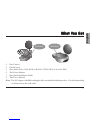 3
3
-
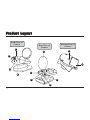 4
4
-
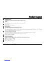 5
5
-
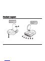 6
6
-
 7
7
-
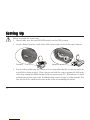 8
8
-
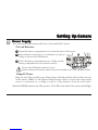 9
9
-
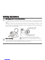 10
10
-
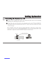 11
11
-
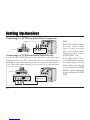 12
12
-
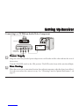 13
13
-
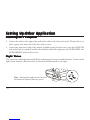 14
14
-
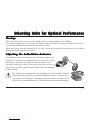 15
15
-
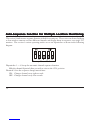 16
16
-
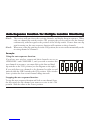 17
17
-
 18
18
-
 19
19
-
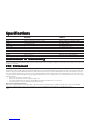 20
20
-
 21
21
-
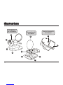 22
22
-
 23
23
-
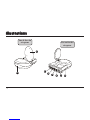 24
24
-
 25
25
-
 26
26
-
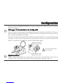 27
27
-
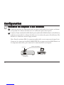 28
28
-
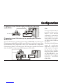 29
29
-
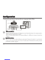 30
30
-
 31
31
-
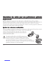 32
32
-
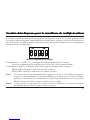 33
33
-
 34
34
-
 35
35
-
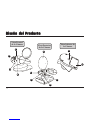 36
36
-
 37
37
-
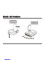 38
38
-
 39
39
-
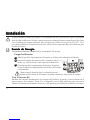 40
40
-
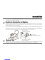 41
41
-
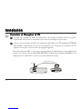 42
42
-
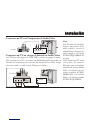 43
43
-
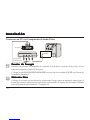 44
44
-
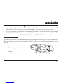 45
45
-
 46
46
-
 47
47
-
 48
48
-
 49
49
-
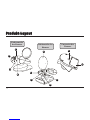 50
50
-
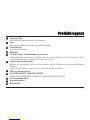 51
51
-
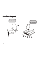 52
52
-
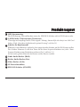 53
53
-
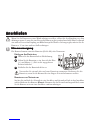 54
54
-
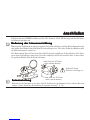 55
55
-
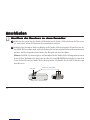 56
56
-
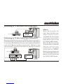 57
57
-
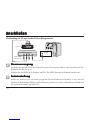 58
58
-
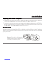 59
59
-
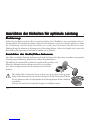 60
60
-
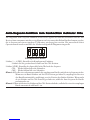 61
61
-
 62
62
-
 63
63
-
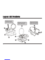 64
64
-
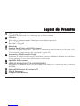 65
65
-
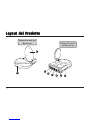 66
66
-
 67
67
-
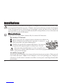 68
68
-
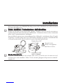 69
69
-
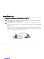 70
70
-
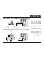 71
71
-
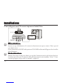 72
72
-
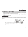 73
73
-
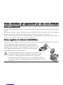 74
74
-
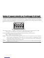 75
75
-
 76
76
-
 77
77
-
 78
78


TRANWO Technology 3010 Manual de usuario
- Tipo
- Manual de usuario
- Este manual también es adecuado para
En otros idiomas
- français: TRANWO Technology 3010 Manuel utilisateur
- italiano: TRANWO Technology 3010 Manuale utente
- English: TRANWO Technology 3010 User manual
Otros documentos
-
SWITEL BC109 El manual del propietario
-
-
The Singing Machine iSM-1010 Manual de usuario
-
Marmitek MegaView 70 Manual de usuario
-
-
Marmitek A/V transmitters over Coax and CAT5: MegaVideo 55 Manual de usuario
-
-
-