
a
Installation & User’s Guide
a Gur’a Para Instalacih y Uso
m Guide d’installation et mode
d’emploi
1. Alr dlrectlon tab
2. Alr louvers
3. Slide-out filter
4. Front panel
5. Control panel
1. Tablllla de Dlrecckh
de Alre
2. Rejlllas del Alre
3. Flltro Desllzable
4. Panel Delantero
5. Panel de Control
m .
1. Bouton de hglage de la
clrculatlon de I’alr
2.
Jalousies
3. Flltre coullssant
4. Panneau avant
5. Tableau de commande
ROOM AIR
CONDITIONER
ACONDICIONADOR
DE AIRE
CLIMATISEUR
1164939
“h/3

Page
A. Note To You 4 . ......................................................................
Important Safety Instructions..
6
...........................................
Electrical Requirements..
... I__....................-....-
............. 8
Receptacle wiring
.......................................................
10
Electrical requirements
.................... -. .......................
10
Electrical connectioh
.................................................
10
Installation Instructions
....................................................
12
Before you begin
........................................................ 12
Tools/supplies
needed.. ... .- ......................................
14
Parts supplied for installation
................................... 14
Window installation
....................................................
16
Through-the-wall
Installation ....................................
22
Operating Instructions
......................................................
26
Starting your
air conditioner .....................................
26
Using the HEAT settings
............................................
26
Using the air control
.................................................
-28
Changing air direction
..............................................
-28
Cleaning Instructions
........................................................
30
Cleaning the air
filter.. ................................................
30
Cleaning the front
panel ...........................................
-30
Maintenance Instructions
................................................ -32
Annual maintenance
.................................................. 32
Repairing paint
damage
............................................ .34
Saving energy
............................................................. 34
lf You Need Service
or Assistance..
................................
.36
Warranty
.............................................................................
42
Pdgina
Sirvase Notar..
.......................................................
1.;.
............
-4 ..
lnstrucciones Importantes de Seguridad
.
..1........................ 6
Requerimientos
Electricos.. ........................................... 8
Alambrado
del tomacorriente
......................................
10
Requerimientos electricos
........................................... 10
Cortexi&
elt5ctrica.. ...................................................... 10
lnstrucclones
da Instalaci6n
.............................
. .................
12
Antes da comanzar
.......................................................
12
Herramientaslmateriales nacesarios
..........................
14
Piexas
suministradas para la
instalaci6n..
................. 14
Instalaci6n
en la ventana .............................................
16
Instataci6n en la pared
.................................................
22
lnstrucciones de Funcionamiento
...................................... 26
Prendiendo
su acondicionador de aire.. ..................... 26
Usando 10s ajustes de CALEFACCICN
....................... 26
Usando
el control del aire
...........................................
.28
Cambiando la diraccion del aire
.................................. 28
lnstrucciones para Limpieza
...............................................
30
Limpieza del filtro de aire .............................................
30
Limpieza
del panel delantero
.......................................
30
lnstrucciones
de Mantenimiento
.......................................
.32
Mantenimiento anual
.................................................... 32
Reparation
de la pintura dafiada
...............................
.34
Ahorro de energia
.........................................................
34
Si Necesita Servicio o Ayuda ..............................................
36
Garantia
.................................................................................
42
Thank you for buying this appliance. Please complete and
mail the Owner Registration Card provided with the
product. Then, complete the form below. Have this information
ready if you need service or call with a question.
l
Copy model and serial numbers from label (see figure at
right). Also copy purchase date from the sales slip.
. Keep this book and sales slip together in a handy place for
future reference.
Model Number
Le agradecemos que haya comprado este artefacto. Por
favor completar y enviar por correo la tarjeta de Registro
de Propietario provista con el producto. Luego. completar el
formulario que se incluye a continuation. Tenga esta
information a la mano si usted necesita servicio o desea hater
una consulta.
l
Copie el nlimero del modelo y el nljmero de serie de la
etiqueta (ver figura a la derecha). Tambien copie la fecha de
compra que aparece en el recibo de venta.
l
Mantener juntos este libro y el recibo de compra en un lugar
apropiado para referencia futura.
Serial Number
Numero de Modelo
Purchase Date
Numero de Serie
Service Company and Phone Number
Fecha de Compra
Compafiia de Servicio y Numero de Telefono
La página se está cargando...

q
A Note To You
Your safety is
important to us.
This guide contains safety symbols and statements. Please
pay special attention to the symbols and follow any instructions
given. Here is a brief explanation of the use of each symbol.
This symbol alerts you to such dangers as personal injury,
burns, fire and electrical shock.
This symbol helps you avoid actions which could cause
product damage (scratches, dents, etc.) and damage to
your personal property.
q
Siiiase
Notar
Su seguridad es muy
importante para nosotros.
Esta guia contiene numerosos simbolos y advertencias de
seguridad. Le rogamos prestar atencion especial a 10s
sirnbolos y seguir las instrucciones indicadas. A continuation
se incluye una breve explication del uso de cada simbolo.
I
Este simbolo le advierte de que existe la posibilidad de
que ocurra una lesion personal, quemaduras, incendio y
choque ektrico.
I
Este simbolo le ayuda a evitar situaciones que podrian
causar daiio al product0 (rayaduras, picaduras, etc.) y
daiio a sus bienes personales.
I
La página se está cargando...

q
Important
Safety
lnstrulctions
To reduce the risk of fire, electrical shock or personal
injury when using your air conditioner, follow these
basic precautions:
l
Read all instructions before using your air conditioner.
l
Complete the installation instructions as described in this
manual.
l
Never allow children to operate or play with the air
conditioner.
l
DO NOT operate the air conditioner with the front panel
removed.
9 Disconnect power supply cord from receptacle before
servicing. Refer to model and serial number label for
BTU capacity, amperage, vokage and refrigerant charge
specifications.
l
Never clean air conditioner parts with flammable fluids.
The fumes can create a fire hazard or explosion.
l
FOR YOUR SAFETY
l
DO NOT STORE OR USE GASOLINE OR OTHER
FLAMMABLE VAPORS AND LIQUIDS IN THE VICINITY
OF THIS OR ANY OTHER APPLIANCE. THE FUMES
CAN CREATE A FIRE HAZARD OR EXPLOSION.
-SAVE THESE INSTRUCTIONS-
It is your responsibility to be sure your
air conditioner:
l
is installed in a window or wall that will support the weight of
the unit.
l
is installed and secured according to the installation
instructions described in this manual.
l
is connected only to the proper kind of outlet, with the
correct electrical supply and grounding. (See “Electrical
Requirements” on page 8.)
l
is the proper size for the area you want to cool.
l
is used only for the job it is designed to do.
. is not used by children or anyone unable to operate it
properly.
l
is properly maintained.
Also, remove the Energy Label and Buy Guide. Use a damp
cloth to take off any glue residue. Do not use sharp instru-
ments, flammable fluids or abrasive cleaner. These can
damage the material.
q
lnstrucciones
Importantes
de-Seguridad
Para reducir el riesgo de incendio, choque el6ctrico o
lesi6n personal cuando use su acondicionador de aire,
siga estas precauciones blsicas:
l
Lea todas las instrucciones antes de usar su
acondicionador de aire.
l
Seguir las instrucciones de instalacion coma se indica en
este manual.
l
Nunca permitir que 10s niiios hagan funcionar o jueguen
con el acondicionador de aire.
l
NO hater funcionar el acondicionador de aire sin el panel
delantero.
l
Desertchufar el cordon electrico antes de efectuar el
mantenimiento. Ver el numero de modelo y serie para la
capacidad de BTU, amperaje, voltaje y especificaciones
sobre la carga de refrigerante.
l
Nunca limpiar las piezas del acondicionador de aire con
liquidos inflamables. Los vapores emanados pueden
crear un riesgo de incendio o explosion.
l
PARA SU SEGURIDAD
l
NO USE 0 ALMACENE GASOLINA U OTROS VAPORES
0 LIQUIDOS INFlAMABLES EN LA PROXIMIDAD DE
ESTE 0 CUALQUIER OTRO ARTEFACTO. LOS
VAPORES EMANADOS PUEDEN CREAR UN RIESGO
DE INCENDIO 0 EXPLOSION.
-CONSERVAR ESTAS INSTRUCCIONES-
Es su responsabilidad asegurarse de
que su acondicionador de aire:
l
esta instalado en una ventana o pared que soportara el
peso del artefacto.
l
esta instalado y asegurado de acuerdo a las instrucciones
de instalacion descritas en este manual.
l
esta conectado solamente al tip0 de tomacorriente
adecuado, con el suministro de energia electrica y puesta a
tierra correctos (ver “Requerimientos Elbctricos” en la
pigina 8).
l
es del tamaho adecuado para el espacio que desea enfriar.
l
se usa solamente para el fin que fue disefiado.
l
no sea usado por nkios o por alguien que no este
capacitado para hacerlo funcionar en forma debida.
l
recibe mantenimiento apropiado.
Ademds debe quitar la Etiqueta de Energfa y de la Guia de
Compra. Use un paiio htimedo para sacar cualquier resto de
goma. No use instrumentos afilados, liquidos inflamables o
detergentes abrasivos. Estos pueden daiiar el material.
La página se está cargando...

q
Electrical
Requirements
Electrical Shock Hazard
l
Electrical ground is required on this appliance.
l
Grounding wire must be connected to ground screw
(located in lower right corner of unit) when air conditioner
is in cabinet.
l
If cold water pipe is interrupted by plastic, non-metallic
gaskets, or other insulating materials, DO NOT use it for
grounding.
l
DO NOT ground to a gas pipe.
l
DO NOT modify the power supply cord. If it does not fit
the outlet, have a proper outlet installed by a qualified
electrician.
l
DO NOT have a fuse in the neutral or grounding circuit.
l
DO NOT use an extension cord with this appliance.
l
Check with a qualified electrician if you are unsure
whether the appliance is properly grounded.
Failure to follow these precautions could result in electrical
shock, serious injury, or death.
OBSERVE ALL LOCAL CODES AND ORDINANCES.
DO NOT, UNDER ANY CIRCUMSTANCES, REMOVE THE
POWER SUPPLY CORD GROUNDING PRONG.
NOTE: If codes permit, and a separate grounding wire is
used, it is recommended that a qualified electrician determine
that the grounding path is adequate and not interrupted by
plastic, non-metallic gaskets, or other insulating materials.
To the right are electrical plug variations. Choose the plug
that matches your unit’s plug. Then, use the chart below to
find the voltage and ampere requirements for your unit, and
the gauge of copper wire required for the receptacle wiring.
I
PLUG REQUIREMENTS
COPPER WIRE
1
l
115 vdt (103.5 min.-126.5 max.)
14 gauge
l
O-12 amperes
l
15 amp time-delay fuse or circuit
breaker.
2
l
230 vdt (207 min.-253 max.) 14 gauge
or
l
2301’208 volt (197.6 min.-253 max.)
l
O-12 amperes
l
15 amp timedelay fuse or circuit
breaker.
3
l
230 vdt (207 min.-253 max.)
12 gauge
or
l
23O&O8 volt (197.6 min.-253 max.)
l
O-16 amperes
l
20 amp time-delay fuse or circuit
breaker.
4
l
230 vdt (207 min.-253 max.)
1ogeuge
or
l
230/208 volt (197.6 min.-253 max.)
l
O-24 amperes
l
30 amp timedelay fuse or circuit
breaker.
q
Requerimientos
Ektricos
Rieego de Choque El6ctrico
l
Este artefacto debe ser puesto a tierra.
l
El alambre de puesta a tierra debe ser conectado al
tornillo de puesta a tierra (situado en la esquina derecha
inferior del artefacto) cuando el acondicionador de aire
est& en la caja rnetilica.
l
Si la tuberia del agua fria estl interrumpida con
empaquetaduras plisticas, no meMicas u otros
materiales aisladores. NO usarla para la puesta a tierra.
l
NO poner a tierra en una tuberia de gas.
l
NO modificar el cable de suministro de energia. Si no
ajusta bien en el tomacorriente, hater instalar un
tomacorriente adecuado por un electricista calificado.
l
NO usar un fusible en el circuit0 de puesta a tierra o
neutral.
l
NO SE DEBE USAR UN CABLE DE EXTENSION CON
ESTE ARTEFACTO.
l
Consultar con un electricista calificado para asegurarse
de que el artefacto esti debidamente puesto a tierra.
El incumplimiento de estas precauciones puede resultar
en choque el&trico, lesi6n grave o la muerle.
OBSERVAR TODOS LOS CODIGOS Y REGLAMENTOS
LOCALES.
BAJO NINGUNA CIRCUNSTANCIA DEBE SACAR LA
CLAVlJA DE PUESTA A TIERRA DEL CABLE DE
ENERGIA ELECTRICA.
NOTA: Si 10s c6digos lo permiten y se usa un alambre de
puesta a tierra separado, se recomienda que un electricista
calificado determine si el trayecto de la puesta a tierra es
adecuado y no Bsta interrumpido por empaquetaduras
plbticas, no rnet&zas u otros materiales aisladores.
La ilustraci6n a la derecha muestra varias configuraciones de
enchufes el6ctricos. Seleccionar el que corresponda al
enchufe de su artefacto. Luego usar la tabla que se incluye a
continuacidn para encontrar 10s requerimientos de voltaje y
amperes para su artefacto y el calibre del alambre de cobre
requerido para el alambrado del tomacorriente.
_ .- ..-.-. .-
ENCHUFE REQUERIMIENTOS
DE COBRE
1
l
115 vdtios (103.5 min.-126.5 m&X.) Calibre 14
l
O-12 amperes
l
Disyuntor o fusible de acctin
ret&dada de 15 amp.
2
l
230 vdtios (207 mh-253 mk) o
Calibre 14
l
230/206 voltios (197,6 min.-253
mhx.)
l
O-12 amperes
l
Disyuntor o fusible de accidn
ratarclsda de 15 amp.
continlia en la @gina 10
La página se está cargando...

Receptacle wiring
See the chart on page 8 for minimum gauge for receptacle
wiring. Use copper wire only. It is the responsibility of the
consumer to provide proper and adequate receptacle wiring,
installed by a qualified electrician. Observe the National
Electrical Code and all local governing codes and ordinances.
Electrical requirements
See the chart on page 8 for the vottage and amperes neces-
sary for this appliance. Use a time-delay fuse or time-delay
circuit breaker. It is required that a separate circuit, serving
only this appliance, be provided.
Electrical connection
Electrical ground is required on this appliance.
Grounding method
For your personal safety, this appliance must be grounded.
This air conditioner is equipped with a power supply cord
containing a 3-prong grounding plug. To minimize possible
shock hazard, the cord must be plugged into a mating 3-prong
grounding-type wall receptacle, grounded in accordance with
the National Electrical Code (ANSl/NFPA 704atest edition) and
all local codes and ordinances. If a mating wall receptacle is
not available, it is the responsibility of the consumer to have a
proper wall receptacle installed by a qualified electrician.
I
ENCHUFE REQUERIMIENTOS
ALAMBRE
DE COBRE
3
l
230 vdtios (207 mh-253 m&) 0 Calibre 12
l
2301208 voltios (197,6 min.-253
m&x.)
l
O-16 amperes
l
Disyuntor o fusible de acci6n
retardada de 20 amp.
4
l
230 vdtios (207 mh-253 mhx.) 0
Calibre 10
l
2301‘206 voltios (197,6 mh-253
m&x.)
l
O-24 amperes
l
Disyuntor o fusible de accidn
retarded9 de 30 amp.
Alambrado del
tomacorriente
Ver en la tabla de la pagina 8 el calibre minimo para el
alambrado del tomacorriente. Usar alambre de cobre
solamente. Es la responsabilidad del consumidor proveer
alambrado del tomacorriente adecuado y apropiado, instalado
por un electricista calificado. Cumplir el C6digo National de
Electricidad y todos 10s codigos y reglamentos locales
vigentes.
Requerimientos ektricos
Ver en la tabla de la pagina 8 el voitaje y amperes necesarios
para este artefacto. Usar un fusible de action retardada o
disyuntor de action retardada. Se requiere que se provea un
circuit0 separado para ser usado por este artefacto solamente.
Conexi6n ektrica
Este artefacto debe ser puesto a tierra.
Metodo recomendado para
la puesta a tierra
Para su seguridad personal este artefacto debe ser puesto a
tierra. El acondicionador de aire esta equipado con un cable
electrico provisto de un enchufe de puesta a tierra de tres
clavijas. Para reducir a un minimo el riesgo de choque, el
cable debe ser enchufado en un tomacorriente mural de tres
clavijas, puesto a tierra de acuerdo con la tiltima edicidn del
Codigo National de Electricidad (ANSIiNFPA 70) y todos 10s
codigos y reglamentos locales. Si no se dispone de un
tomacorriente mural adecuado, es la responsabilidad del
consumidor hater instalar un tomacorriente mural adecuado
por un electricista calificado.
10
La página se está cargando...

Installation
Instructions
Proper installation of your air conditioner is important for proper
operation and best cooling results. To avoid any installation
problems and to ensure trouble-free performance of your new
air conditioner, please read these installation instructions, as
well as the operating instructions and electrical requirements
before installing your unit.
IMPORTANT: Observe all governing codes and ordinances.
Personal Injury and Product Damage Hazard
l
Because of the weight and size of the air conditioner, we
recommend that you have someone help you install your
new unit and that you both use proper lifting techniques.
l
Inspect the condition of the window or wall where the air
conditioner will be installed. Be sure it will support the
weight of the unit.
l
Handle the air conditioner with care. Watch out for the
sharp metal fins on the front and rear coils.
l
Be sure your air conditioner does not fall out of the
opening during installation.
l
Do not install the air conditioner in an area where the
front panel will be exposed to heat sources that will raise
the panel surface temperature above 120°F (50°C).
Failure to follow these precautions could result in personal
injury or product damage.
Before you begin
Check the window/wall location where the air conditioner will
be installed for the following:
l
The opening/window is large enough. (See Figure 5
for necessary window measurements. See Figure 6
for necessary wall opening measurements.)
l
The wall/window is sturdy enough to support the weight
of the air conditioner - 145 to 200 pounds (65.3 to
90 kg).
l
An electrical supply is within reach of the power supply cord.
l
Air will move freely into rooms to be cooled/heated.
q
Instrucciones
de lnstalaci6n
La buena instalacion de su acondicionador de aire es
importante para el buen funcionamiento y obtener 10s mejores
resultados del enfriamiento. Para evitar cualquier problema de
instalacion y asegurar de que su nuevo acondicionador de
aire funcione sin problemas, le rogamos leer estas
instrucciones de instalacion asi coma tambien las
instrucciones de funcionamiento y 10s requerimientos
electricos antes de instalar su artefacto.
IMPORTANTE: Cumplir todos fos codigos y reglamentos
vigentes.
Riesgo de Lesi6n Personal y Daiio al Product0
l
Debido al peso y tamario del acondicionador de aire,
recomendamos que alguien le ayude a instalar su
artefacto y que se usen tecnicas adecuadas para
levantarlo.
l
lnspeccionar el estado de la ventana o pared donde se
instalara el acondicionador de aire. Asegljrese de que
soportara el peso del artefacto.
l
Manipular con cuidado el acondicionador de aire. Prestal
especial atencion a las aletas de metal afiladas en 10s
serpentines traseros y delanteros.
l
Asegurese de que su acondicionador de aire no se caiga
fuera de la abertura durante la instalacion.
l
No instalar el acondicionador de aire en un espacio
donde el panel delantero estara expuesto a fuentes de
calor que elevaran la temperatura de la superfiiie del
panel a mis de 50’ C (120” F).
El incumplimiento de estas precauciones puede resultar er
lesion personal o daho al producto.
Antes de comenzar
Revisar la ubicacion de la ventana/pared donde se instalara el
acondicionador de aire para verificar lo siguiente:
l
Cue la abertura/ventana sea lo suficientemente grande. (Ver
Figura 5 para las medidas necesarias de la ventana. Ver
Figura 6 para las medidas necesarias de la abertura de la
pared.)
l
Clue la ventana/pared sea lo suficientemente resistente para
soportar el peso del acondicionador de aire -65,3 a 90 kg
(145 a 200 libras).
l
Que exista un tornacorriente dentro del alcance del cable
electrico.
l
Libre movimiento del aire a las habitaciones que desea
enfriar/calentar.
12
La página se está cargando...

Tools/supplies needed
(See Figure 7.)
1.
Flat-blade-screwdriver
2.
Tape measure
3.
Utility knife
4.
Socket wrench
5. %s” (11 mm) socket
6. %" (6 mm) socket
7.
Electric drill
8.
%z’ (2 mm) or smaller drill bit
9.
Carpenter’s level
10. Saw
For through-the-wall installation:
11. Wood preservative
12. #10x 1” (25 mm) screws [lo]
Parts supplied for
installation
(See Figure 8.)
A. %” (10 mm) seal strips [5]
B. Side mounting brackets [2]
C. #6 x %” (10 mm) hex-head sheet-metal screws [7]
D. Top mounting channel [l]
E. Filler board [l]
F. #6 x 3/s” (10 mm) round-head sheet-metal screws [4]
G. Window gasket [l]
H. Foam blocks [4]
I. MO x %” (19 mm) round-head wood screws [3]
J. 2%’ (63.2 mm) seal strip [l]
K. Vertical supports [2]
L Angled supports [2]
M. %” (19 mm) round-head bolts [6]
N. Flat washers [6]
0. Lock washers [6]
P. Nuts [6]
Q. Wall rail [l]
R. Foam window rail seal [l]
S. Window lock bracket [l]
T. Plastic drain cup [l]
U. Gum-type sealer [l]
Installation parts are supplied for double-hung windows up to
40” (1016 mm) wide. Installation up to 54” (1372 mm) can be
made with a special ‘Wide-window kit” from your dealer or
authorized service center.
Herramientas/materiales
necesarios
(Ver Figura 7.)
1.
Destornillador plano
2.
Cinta de medir
3.
Cuchillo de uso general
4.
Llave de casquillo
5.
Casquillo de 11 mm (36”)
6.
Casquillo de 6 mm (X”)
7.
Taladro electrico
8.
Broca de 2 mm (%z”) o mas pequeiia
9.
Nivel de carpintero
10.
Serrucho
Para instalacidn en la pared:
11. Presewante de madera
12. Tornillos# 10x25mm(1”)[10]
Piezas suministradas para
la instalacih
(Ver Figura 8.)
k Cintas obturadoras de 10 mm (%“) [5]
B. Soportes de montaje lateral [2]
C. Tornillos para metal de cabeza hexagonal #8 x 10 mm
(w”) PI
D. Canaleta de montaje superior [l]
E. Tabla de relleno [l]
F. Tornillos para metal de cabeza redonda #8 x 10 mm (3/g”) [4]
G. Empaquetadura de la ventana [l]
H. Bloques de espuma [4]
I. Tornillos para madera de cabeza redonda #l 0 x 19 mm
W") [31
J. Cinta obturadora de 63,2 mm (2%“) [l]
K Soportes verticales [2]
L. Soportes en dngulo [2]
M. Pernos de cabeza redonda de 19 mm (3/411) [6]
N. Arandelas planas [6]
0. Arandelas de seguridad [6]
P. Tuercas [6]
Q. TravesaAo de la pared [l]
R. Obturador de espuma del travesaiio de la ventana [l]
S. Soportes de bloqueo de la ventana [l]
T. Vaso de drenaje de plastico [l]
U. Sellador tipo goma [l]
Las piezas de instalacion han sido suministradas para
ventanas de guillotina de hasta 1016 mm (40”) de ancho. Se
pueden hater instalaciones de hasta 1372 mm (54”) de ancho;
con un Juego Especial para Ventanas Anchas que puede
eoliiitar a au distribuidor o a su centro de servicio autorizado.
14
La página se está cargando...

Window installation
1.
2.
3.
4
5.
6.
7.
8.
9.
10.
11.
Remove the ground wire and screw from the front of
the unit base. Save grounding screw for reattachment in
Step 22. See Figure 9.
Attach Jh. (10 mm) seal strip (A) to bottom of both
side mounting brackets (sides with screw holes). Cut
strips to length and save extra for use later.
Attsch slde mounting brackets (B) to cabinet. Place
side mounting brackets on cabinet so bent edge is toward
front of cabinet. Attach each with hex-head metal
screws (C).
Slide unit out of cabinet. Grasp handle and
slide unit straight out of cabinet. Place unit on
cardboard to protect your floor covering.
Place empty cabinet In window. Lower window sash to
hold cabinet in place. Make sure the cabinet is centered
in the window opening.
Determine proper size for filler board (E). Measure the
distance from the right edge of the cabinet to the inside of
the right window channel (see Figure 10). Then add %”
(3 mm) to that measurement. Repeat for left side.
Cut filler board (E) to size. Cut both edges of the filler
board to the proper size. Cut in from the outside edges.
The outside edges should have screw holes in them.
Apply %’ (10 mm) seal strip (left over from Step 3) to
the filler boards. Apply seal strips to the bottom front
and outside front edges of the filler boards. The top seal
strip goes on the back side of the filler boards. See
Figure 11.
Attach left filler board to cabinet. Pull cabinet part way
out of the window. Then attach the left filler board to the
front of the left side mounting bracket. Use W (10 mm)
round-head metal screws (F). See Figure 12.
Position left filler board in window channel. Place
cabinet back into window. Make sure left filler board sits
tightly against the window channel. See Figure 13.
Attach right filler board to cabinet. Insert right filler
board into right window channel. Push filler board against
right side mounting bracket and attach it with 3/e” (10 mm)
round-head metal screws.
Instalacihn en la ventana.
1.
2.
3.
4.
5.
6.
7.
8.
9.
10.
11.
Sacar el tornillo y el alambre de puests a tierra de la
parte delantera de la base del scondicionador.
Conservar el tornillo de puesta a tierra para volver a
colocarlo en el Paso 22. Ver Figura 9.
Colocer la cinta obturadora de 10 mm (W) (A) en la
parte inferior y en arnbos soportes de montaje lateral
(lsdos con los sgujeros de tornillos). Cottar las tiras a
la medida y guardar el sobrante para usarlo
posterformente.
lnstalar en la caja metilics los sopor&s de montaje
lateral (B). Colocar 10s soportes de montaje lateral en la
caja met&a de modo que el borde curve quede hacia el
frente de la caja met&a. lnstalar cada uno con tomillos
para metal de cabeza hexagonal (C).
Desllzar el scondlclonador de alre fuera de la caja
rnet8lica. Tirar de la manija derecho hacia afuera de la
caja. Colocar la unidad sobre un pedazo de carl6n para
proteger el revestimiento de su piso.
Colocar la caja met&lice vacia en la ventana Bajar la
hoja de la ventana para sujetar la caja metslica en su
lugar. Asegurarse de que la caja metelica este en el
centro de la aberlura de la ventana.
Determinar el tamaiio adecuado para la tabla de
relleno (E). Medir la distancia desde el borde derecho de
la caja metdlica hasta el interior de la canaleta derecha
de la ventana (ver Figura 10). Luego agregar 3 mm (j/g”)
a esa rnedida. Repetir para el lado izquierdo.
Cortar la tabla de relleno (E) al tamaiio deseado.
Cortar ambos hordes de la tabla de relleno al tamaiio
adecuado. Cortar desde 10s bordes exteriores. Los
bordes exteriores deben tener agujeros para tornillos.
Aplicar cinta obturadora de 10 mm (%.) (el restante
del Paso 3) a las tablas de relleno. Aplicar las tiras
obturadoras a la parte delantera inferior y a 10s bordes
delanteros exteriores de las tablas de relleno. La cinta
obturadora superior se coloca en la parte de at& de las
tablas de relleno. Ver Figura 11.
lnstalar la tabla de relleno izquierda en la caja
met8lica. Tirar la caja metelica un poco hacia afuera de
la ventana. Luego instalar la tabla de relleno izquierda a
la parte delantera del soporte de montaje lateral
izquierdo. Usar tornillos para metal de cabeza redonda de
10 mm (%“) (F). Ver Figure 12.
Colocar la tabla de relleno izquierda en la canaleta de
la ventana. Volver a colocar la caja met&lica en la
ventana. Asegurarse de que la tabla de relleno izquierda
descansa firmemente contra la canaleta de la ventana.
Ver Figure 13.
lnstalar la tabla de relleno derecha en la caja metilica.
lnsertar la tabla de relleno derecha en la canaleta
derecha de la ventana. Empujar la tabla de relleno contra
el soporte de montaje lateral derecho y sujetarla con 10s
tornillos de metal de cabeza redonda de 10 mm (3/g”).
16
La página se está cargando...

12.
13.
14.
15.
16.
17.
18.
Apply window gasket (G). Measure from right inside
edge of window frame to left inside edge. Then cut the
window gasket, with square ends, to fit. Raise window
sash slightly and place gasket over the top mounting
channel and top edge of filler boards. See Figure 14.
Make sure filler boards are as far forward (toward
inside room) in window channels as possible.
Insert foam blocks (H). Measure the distance between
the filler board and the back window channel edge. Cut
foam blocks W (6 mm) wider than measurement. Insert
foam blocks into window channels - behind filler boards.
See Figure 15.
Fasten cabinet to window sill. Lower window sash firmly
onto cabinet. Place a carpenter’s level inside the cabinet
and make sure cabinet is level side-to-side. Then drill
starter holes into the cabinet base and the window sill.
Use round-head wood screws (I) to fasten cabinet to
window sill. See Figure 16.
Make sure cabinet has proper outward slope. Place
carpenter’s level in the right side of the cabinet. There
should be a W bubble tilt (l/4* [6 mm]) tilt toward the
outside. Repeat for left side of cabinet. See Figure 17.
Attach 2%’ (64 mm) seal strip (J) to inside of cabinet.
Make sure the seal strip is flush with the front edge of the
cabinet. This seal strip provides a seal between the air
conditioner base and the cabinet.
Assemble the outside support. Attach the vertical
supports (K) to the angle supports (L). Use the round-head
bolts (M), flat washers (N), lock washers (0) and the nuts
(P) for attachments. Then attach these supports to the
bottom of the cabinet, but DO NOT tighten the botts at this
time.
Attach the wall rail (Q) the bottom of the supports, and
slide the support assembly toward the house until the wall
rail presses firmly against the wall. See Figure 18.
Now tighten all bolts. Tighten angled support bolts last
so wall rail fits tightly against the house.
NOTE: If your house is constructed of materials that could
be damaged by the wall rail, fasten a board between the
wall rail and the house.
12.
13.
14.
15.
16.
17.
18.
Colocar la empaquetadura de la ventana (G). Medir
desde el borde interior derecho del marco de la ventana al
borde interior izquierdo. Luego cortar la empaquetadura
de la ventana con 10s extremes cuadrados para que calce.
Levantar levemente la hoja de la ventana y colocar la
empaquetadura sobre la canaleta de montaje superior y
en las tablas de relleno del borde superior. Ver Figura 14.
Asegurarse de que las tablas de relleno estCn tan
adelante (hacia adentro de la habltacibn) en las
canaletas de la ventana coma sea posible.
Insertar los bloques de espuma (H). Medir la distancia
entre la tabla de relleno y el borde de la canaleta trasera
de la ventana. Cortar bloques de espuma 6 mm (I/I*) mas
anchos que la medida. lnsertar los bloques de espuma
dentro de las canal&as de la ventana detrb de las tablas
de relleno. Ver Figura 15.
lnstalar la caja met4ica en la batiente de la ventana.
Bajar la hoja de la ventana firmemente hasta la caja
met&a. Colocar un nivel de carpintero dentro de la caja
met&a y asegurarse de que la caja esta nivelada de un
lado al otro. Luego taladrar orificios gufa en la base de la
caja met&a y en la batiente de la ventana. Usar 10s
tornillos de madera de cabeza redonda (I) para sujetar la
caja rnetalica a la batiente de la ventana. Ver Figura 16.
Asegurese de que la caja metilica tenga una
inclination hacia afuera adecuada. Colocar el nivel de
carpintero en el lado derecho de la caja rnetalica. Debe
tener una inclination hacia afuera de aproximadamente
media burbuja (6 mm [X7). Fiepetir para el lado izquierdo
de la caja metalica Ver Figura 17.
Instalar la cinta obturadora de 64 mm (2%‘) (J) en la
parte interior de la caja metllica. Asegurarse de que la
cinta obturadora este al ras con el borde delantero de la
caja met&a. Esta cinta obturadora se coloca entre la
base del acondicionador de aire y la caja met&a.
Montaje del soporte exterior. Unir 10s soportes verticales
(K) a 10s soportes angulares (L). Usar 10s pernos de
cabeza redonda (M), las arandelas planas (N), las
arandelas de seguridad (0) y las tuercas (P) coma
sujeciones. Luego instalar estos soportes en la parte
inferior de la caja metalica, pero NO apretar 10s pernos en
este momento.
lnstalar el travesafio de la pared (Cl) en la parte inferior
de 10s soportes y deslizar el conjunto del soporte contra la
pared de la casa hasta que el travesafio descanse
firmemente contra la pared. Ver Figura 18.
Ahora apretar todos 10s pernos. Apretar al final 10s
pernos del soporte angular para que el travesafio de la
pared ajuste firmemente contra la pared de la casa.
NOTA: Si su casa esta construida de materiales que
pueden daharse al instalar el travesaho de la pared,
instalar una tabla entre el travesafio y la pared de la casa.
18
La página se está cargando...

19. install foam window rail seal (R), the window lock
bracket (S), and the plastic drain cup (T). See
Figure 19.
l
Insert foam rail seal between the top of the lower
window sash and the glass of the upper window.
l
Place window lock bracket on top of lower window
sash and against upper window sash. Drill a starter
hole through the lock bracket into the window sash.
Attach window lock bracket.
l
Insert plastic drain cup into hole in right side of
cabinet base.
Personal Injury and Product Damage Hazard
Install window lock bracket to prevent air conditioner
Failure to do so could result in personal injury or product
20. Seal any small openings around window with gum-
type sealer (U).
21. Insert air conditioner into cabinet.
22. Reattach ground wire with grounding screw. Put
excess grounded wire between the coils and the cabinet.
Electrical Shock Hazard
Air conditioner ground wire must be attached to the
cabinet.
Failure to do so could result in electrical shock.
23. Attach the front panel. Remove the 2 front panel screws
from unit base. Replace front panel by pushing it straight
on and then lowering it slightly to lock it in place. Attach
bottom front of panel by reinserting the 2 front panel
screws. See Figure 20.
19. lnstalar el obturador de espuma dei travesafio de la
ventana (R), el soporte de bloqueo de la ventana (S) y
la taza de drenaje de pl6stlco (T). Ver Figura 19.
l
lnsertar el obturador de espuma del travesafio entre la
pane superior de la hoja inferior de la ventana y el vidrio
de la ventana superior.
l
Colocar el soporte de bloqueo de la ventana en la parte
superior de la hoja inferior de la ventana y contra la hoja
de la ventana superior. Taladrar un agujero de guia a
trav& del soporte de bloqueo hacia la hoja de la
ventana. lnstalar el soporte de bloqueo de la ventana.
l
lnsertar la taza de drenaje de plastico en el agujero en
el lado derecho de la base de la caja metalica.
r
Riesgo de Lesion Personal y Dafio del Product0
lnstalar el soporte de bloqueo de la ventana para evitar
que el acondicionador de aire se caiga fuera de la ventana.
De lo contrario se pueden causar lesiones personales o
daiio al producto.
20. Sellar las pequeiias aberturas airededor de la ventana
con obturador tipo goma (U).
21. lnsertar el acondicionador de aire en la caja metiiica.
22. Volver a conectar ei alambre de puesta a tierra al
tornillo de puesta a tierra. Colocar el exceso de alambre
entre 10s serpentine9 y la caja met&a.
Riesgo de Choque El6ctrlco
El alambre de puesta a tierra del acondicionador de aire
debe de ser instalado en la caja metalica. De lo contrario
se puede producir un choque el6ctrico.
23. lnstalar el panel delantero. Sacar 10s 2 tornillos del panel
delantero de la base del acondicionador. Volver a colocar
el panel delantero empujandolo derecho y luego
haciendolo descender levemente para que calce en su
lugar. lnstalar la parte inferior del panel volviendo a
insertar 10s 2 tornillos del panel delantero. Ver Figura 20.
20
La página se está cargando...

Through-the-wall
installation
It is the consumer’s responsibility and obligation to have this
product installed by a qualified technician who is familiar with
through-the-wall room air conditioner installations.
1.
2.
3.
4.
5.
6.
Cut an opening through the wail. Remove any insulation
and keep for Step 8.
Measure depth of wall opening and construct finish
frame. Use 1’ (25 mm) or heavier lumber for wood frame
construction. When using a wood, metal or plastic molding,
the finish frame should line up with the inside wall. lf a
plastered wall is to be flush with the cabinet, and no
molding is used, the finish frame must be set W (13 mm)
into the wall. See Figures 21 and 22 for Frame Construc-
tion and Brick Veneer Construction information. See Figure
23 for finish frame sizes.
NOTE: Apply wood preservative to the surface exposed to
the outside.
Insert finish frame into wail opening. Square and level
the frame. Nail frame securely to the wall studs.
Remove the ground wire and screw from the front of
the unit base. Save grounding screw for reattachment in
Step 13. See Figure 24.
Slide unit out of cabinet. Grasp handle and slide unit
straight out of cabinet. Place unit on cardboard to protect
your floor covering. See Figure 25.
Insert cabinet into the wall opening. The top of the
cabinet should extend 9’~” (13 mm) into the room. If there is
trim, the cabinet should extend %I” (13 mm) passed the trim.
Make sure the air conditioner cabinet has the proper
Failure to do so could result in damage to the floor or wall.
7. Check the outward slope of the cabinet. Place a
carpenter’s level inside the cabinet on the right side. There
should be 1 bubble (%” [6 mm]) slope toward the outside.
Also check the left side. See Figure 26.
8. Seal opening between cabinet and finish frame. Use the
insulation removed in Step 1.
Instalaci6n en la pared
Es responsabilidad y obligaci6n del consumidor de que este
product0 sea instalado por un tecnico calificado familiarizado
con las instalaciones de acondicionadores de aire en la pared.
1. Cortar una abertura en la pared. Sacar el aislamiento y
guardarlo para usarlo en el Paso 8.
2. Medir la profundidad de la abertura de la pared y
construir el rnarco de acabado. Usar madera de 25 mm
(1’) o ITI& gruesa para la construcci6n del marco de
madera. Cuando se usa una moldura de madera, de
pl&stico o de metal, el marco de acabado debe estar
alineado con la pared interior. Si la pared enyesada debe
quedar a ras con la caja tnettilica y no se usa moldura, el
marco de acabado debe e-star 13 mm (W) hacia dentro de
la pared. Ver las Figuras 21 y 22 para informacibn sobre la
construcci6n del marco y la construccidn del revestimiento
de ladrillo. Ver la Figura 23 para 10s tamahos de
10s
marcos de acabado.
NOTA: Aplicar preservante para madera a la superficie
expuesta al exterior.
3. lnsertar el rnarco de acabado en la abertura de la pared.
Escuadrar y nivelar el marco. Sujetar firmemente con clavos
el marco a 10s rnontantes de la pared.
4. Sacar el alambre de puesta a tierra y el tornillo de la
parte delantera de la base del artefacto. Guardar el
tornillo de puesta a tierra para volver a colocarlo en el Paso
13. Ver Figura 24.
5 Deslizar el attefacto fuera de la caja meMica. Tirar de la
manija y deslizar el acondicionador de aire derecho fuera
de la caja rnetalica. Colocar el artefacto sobre un cart&i
para proteger sus alfombras. Ver Figura 25.
6. lnsertar la caja metilica en la abertura de la pared. La
parte superior de la caja rnetelica debe exlenderse
13
mm
(%‘I) hacia la habitaci6n. Si existe guarnicibn, la caja
met&lica debe extenderse 13 mm (I/Z”) m&s alli de la
.,
guarncton.
Daiios Materiales
Asegljrese de que la caja metAlica del acondicionador de
aire estb inclinada hacia fuera de modo que el agua de
condensacibn escurra hacia el exterior.
De lo contrario. se puede causar daiio al revestimiento del
piso o a la pared.
7. Verificar la inclinackn exterior de la caja rnettilica.
Colocar un nivel de carpintero dentro de la caja metalica en
el lado derecho. Debe tener una inclinacibn hacia afuera de
aproximadamente una burbuja (6 mm [X1’]). Revisar
tambi6n el lado izquierdo. Ver Figura 26.
8. Obturar la abertura entre la caja metelice y el rnarco de
acabado. Usar el aislamiento que se sac6 en el Paso 1.
22
La página se está cargando...

9.
10.
11.
12.
13.
Attach cabinet to finish frame. Drill 4 holes on each
side and 2 holes in the top of the cabinet into the finish
frame. Use #lO x 1” (25 mm) wood screws to attach
cabinet to the frame. See Figure 27.
IMPORTANT: Do not overtighten screws or the cabinet
will distort and provide a poor air seal between the
cabinet and the air conditioner.
Place the 2%’ (63.5 mm) seal strip (J) inside the
cabinet. Make sure the seal is flush with the cabinet front
edge. See Figure 26.
NOTE: This seal strip fits between the air conditioner
base and the cabinet.
Insert drain cup (T). Place drain cup through hole in
cabinet rail. See Figure 29.
Insert air conditioner into cabinet.
Reattach ground wire with grounding screw. Put
excess grounded wire between the coils and the cabinet.
Electrical Shock Hazard
Air conditioner ground wire must be attached to the
cabinet.
Failure to do so could resuft in electrical shock.
14. Attach the front panel. Remove the 2 front panel screws
from unit base. Replace front panel by pushing it straight
on and then lowering it slightly to lock it in place. Attach
bottom front of panel by reinserting the 2 front panel
screws. See Figure 30.
15. Caulk all outside wall openings around the installa-
tion and cabinet.
16. Install decorative molding. If desired, install molding
around room side of cabinet.
9.
10.
11.
12.
13.
Colocar la caja metelica en el marco de acabado.
Taladrar 4 agujeros a cada lado y 2 a traves de la pane
superior de la caja rnetalica hacia el marco. Usar 10s
tornillos de madera #lO x 25 mm (1”) para sujetar la caja
metalica al marco. Ver Figura 27.
IMPORTANTE: No apretar demasiado 10s tornillos pues la
caja metalica se deformara y no obturara bien el aire entre
la caja rnetalica y el acondicionador de aire.
Colocar la cinta obturadora de 63,5 mm (2.5’) (J)
dentro de la caja metilica Asegurarse de que la cinta
obturadora este al ras con el borde delantero de la caja
metalica. Ver Figura 26.
NOTA: Esta cinta obturadora calza entre la base del
acondicionador de aire y la caja metalica.
Insertar la taza de drenaje (T). Colocar la taza de
drenaje a traves del agujero en el travesaho de la caja.
Ver Figura 29.
lnsertar el acondicionador de aire en la caja metalica.
Volver a instalar el alambre de puesta tierra en el
tornillo de puesta tlerra. Colocar el exceso del alambre
de puesta a tierra entre 10s serpentines y la caja rnetalica.
El alambre de puesta a tierra del acondicionador de aire
debe ser conectado a la caja rnetllica de lo contrario se
puede ocasionar un choque el6ctrico.
14. lnstalar el panel delantero. Sacar 10s 2 tornillos del panel
delantero que estan en la base del artefacto. Volver a
colocar el panel delantero empujlndolo derecho y luego
haciendolo descender ligeramente para que se trabe en
su lugar. Sujetar la parte inferior del panel delantero
volviendo a insettar 10s 2 tornillos de la base. Ver
Figura 30.
15. Calafatear todas las aberturas de la pared exterior
alrededor de la instalack5n y de la caja meMica.
16. Instalar moldura decorativa. Si se desea, instalar
moldura alrededor de la caja rnetalica por el lado de la
habitation.
La página se está cargando...

m
Operating
Instructions
Starting your air
conditioner
Electrical Shock Hazard
. Plug unit into grounded electrical outlet only.
l
Do not use an extension cord.
l
Do not operate unit with front panel removed.
Failure to do so could result in electrical shock.
See Figures 31 and 32 for control panel variations.
1. Set Air Control to OFF for maximum cooling.
2. Set Fan Control to desired setting.
(All settings below not on all models.)
HI COOL
. . . . . . . . . . . . . . . .._....... e . . . . . . . . . . ..-........ for
maximum
cooling
MED COOL . . . . . . . . . . . . . . . . . . . . . . . . . . . . . . . . . . . . . . . . . . . . . . for
normal
cooling
LO COOL . . . .
. . . . . . . . . . . . . . . .._........................ for
sleeping
comfort
HI HEAT . . . . . . . . . . . . . . . . . . . . . . . . . . . . . . . . . . . . . . . . . . . . . . for maximum
heating
MED HEAT . . . . . . . . . . . . . . . . . . . . . . . . . . . . . . . . . . . . . . . . . . . . . . for normal
heating
LO HEAT . . . . . . . . . . . . . . . . . . . . . . . . . . . . . . . . . . . . . . . . . . . . . . . for
reduced
heating
FAN ONLY . . . . . ..for circulating air without heating or cooling
3. Set Temp Control to number 4 setting (mid-setting). You can
adjust the air conditioner’s performance by resetting the
Thermostat to a higher or lower number. You will need to
experiment to find the setting(s) which work best for you.
NOTE: If you turn your air conditioner off or ii the compressor
turns off when you lower the Thermostat, wait at least 3 minutes
before turning unit back on. Failure to do so could blow a
household fuse or trip a circuit breaker.
Using the HEAT settings
(on some models)
When the outside temperature is 45°F (7°C) or above, the air
conditioner operates as a heat pump and heats the air running
through the unit. When the outside temperature is below 45°F
(7X), the unit switches itself to an electric-resistance heater to
heat the air.
NOTE: This product is not designed to be used as a primary
heat source. It is intended for supplemental heating only.
m
lnstrucciones
de Funciona-
miento
Para poner en marcha su
acondicionador de aire
Riesgo de Choque El6ctrko
l
Enchufar el acondicionador de aire en un tomacorriente
el&trico puesto a tierra solarnente.
l
No usar un cable de extensi6n.
l
No poner en marcha el acondicionador de aire sin tener
instalado el panel delantero.
De lo contrario se puede ocasionar choque el&ztriio.
Ver Figura 31 y 32 para variaciones del panel de control.
1. Colocar el control del aire en la posici6n OFF para
enfriamiento mbirno.
2. Colocar el control del ventilador en el ajuste deseado. (Los
ajustes que se indican a continuaci6n no aparecen en todos
10s modelos.)
HI COOL
. . . . . . . . . . . . . . . . . . . . . . . . ..-........... para
enfriamiento mbimo
MED COOL
. . . . . . . . . . . . . . . . . . . . . . . . . . . . . . . . . . . para
enfriamiento normal
LOW COOL
. . . . . . . . . . . .._._.......-.......-......................-.. para
dormir
HI HEAT . . . . . . . . . . . . . . . . . . . . . ..-..........-...... para
calefaccibn m&xima
MED HEAT
. . . . . . . . . . . . . . . . . . . . ..-............-.. para
calefaccibn normal
LOW HEAT
. . . . . . . . . . . . . . . . . . . . . . . . ..-............... para
calefacci6n baja
FAN ONLY . . . . . . . . . . . . . . . . . . . . . . . . . . . . . . . . . . . . . . . . . . . . . . . . . para
circular aire,
sin calefacci6n ni enlriamiento
3. Colocar el control de la temperatura en el ntimero 4 (valor
medio). Se puede ajustar el rendimiento del acondicionador de
aire cambiando el termostato a un ntimero superior o inferior.
Usted debera experimentar hasta encontrar el ajuste que m8s le
convenga.
NOTA: Si usted apaga el acondicionador de aire o si el compresor
se apaga cuando el termostato se coloca en un nlimero m& bajo,
espere por lo menos 3 minutos antes de volver a poner en marcha
el acondicionador de aire. De lo contrario se puede quemar un
fusible de la casa o disparar un disyuntor de clrcuito.
Como usar 10s ajustes de la
CALEFACCIbN (en algunos
modelos)
Cuando la temperatura exterior es de 7” C (45” F) o superior,
el acondicionador de aire funciona coma una bomba de calor y
calienta el aire que pasa a travbs del artefacto. Cuando la
temperatura interior es inferior a 7” C (45” F), el acondicionador
de aire activa automdticamente al calefactor de resistencia
electrica para calentar el aire.
NOTA: Este product0 no este disefiado para ser usado coma
una fuente primaria de calor. Ha sido diseiiado para calefaccibn
suplementaria solamente.
26
La página se está cargando...

Using the air control
The Air Control draws stale or smoky air from the room,
circulates air in the room, and draws fresh air into the room
from outside.
To exhaust room air
(Figure 33):
l
Set Air Control to EXHAUST.
l
Set Fan Control to desired setting.
l
Set Temp Control to desired setting.
To
circulate
room air
(Figure 34):
l
Set Air Control to OFF.
l
Set Fan Control to desired setting.
l
Set Temp Control to desired setting.
To bring in fresh air
(Figure 35):
(cool only models)
l
Set Air Control to FRESH AIR.
l
Set Fan Control to desired setting.
l
Set Temp Control to desired setting.
NOTE: For maximum performance, the Air Control must be in
the OFF position.
Changing air direction
The louvers in the top section of the air conditioner front panel
control the direction of the cooled(or heated) air. Move the tab
in the direction you want the air to go - UP, DOWN, or
STRAIGHT AHEAD. See Figure 36.
Corn0 usar el control
del aire
El Control del Aire extrae el aire viciado o con humo de la
habitation y trae aire fresco desde afuera hacia la habitation.
Para extraer el aire de la habitackn
(Figura 33):
l
Colocar el Control del Aire (AIR) en EXHAUST.
l
Colocar el Control del Ventilador (FAN) en el ajuste deseado.
l
Colocar el Control de la Temperatura (TEMP) en el ajuste
deseado.
Para hater circular el aire de la
habitacidn
(Figura 34:
l
Colocar el Control del Aire (AIR) en OFF.
l
Colocar el Control del Ventilador (FAN) en el ajuste deseado.
l
Colocar el Control de la Temperatura (TEMP) en el ajuste
deseado.
Para hater entrar aire fresco
(Figura 35):
(modelos de enf riamiento solamente)
l
Colocar el Control del Aire (AIR) en la position FRESH AIR.
l
Colocar el Control del Ventilador (FAN) en el ajuste deseado.
l
Colocar el Control de la Temperatura (TEMP) en el ajuste
deseado.
NOTA: Para mejor rendimiento, el Control del Aire debe estar
en la position OFF.
Cambiando la direcci6n
del aire
Las rejillas en la parte superior del panel delantero del
acondicionador de aire controlan la direction del aire enfriado
(o calentado). Mover las tablillas en la direction que usted
desea que vaya el aire - HACIA ARRIBA, HACIA ABAJO,
DERECHO AL FRENTE. Ver Figura 36.
26
La página se está cargando...

q
Cleaning
Instructions
Proper use and care of your air conditioner will help ensure
longer life of the unit and lower operating costs. Follow these
cleaning instructions.
Electrical Shock and Fire Hazard
l
Unplug power cord from receptacle before cleaning.
l
Do not use flammable fluids, solvents, abrasive cleaners,
or strong detergents.
Failure to follow the above precautions could result in
electrical shock or fire.
Cleaning the air filter
The air fitter is cleanable. A clean filter helps remove dust, lint
and other particles from the air. Check every two weeks to see
if the filter needs to be cleaned. See Figure 37.
1. Remove air filter from front panel.
l
Grasp filter handle.
l
Slide filter straight up and out of the front panel.
2. Clean filter using a vacuum cleaner.
OR
If very dirty, wash fitter with warm water and a mild deter-
gent. Air dry thoroughly before replacing.
3. Replace air fitter.
l
Guide bottom of fitter into filter slot in front panel.
l
Slide filter straight down into front panel.
NOTE: The front panel does not have to be removed to
clean the filter.
Cleaning the front panel
1. Unplug the power cord.
2. Remove the front panel from the unit. See Figure 38.
l
Remove the two screws from the bottom edge of the
front panel.
l
Lift front panel slightly and then pull it toward you.
3. Remove the slide-out air filter from the front panel. Clean it
separately. See “Cleaning the air filter” above.
4. Clean front panel with warm water and a mild soap or
detergent. Use a soft cloth. Rinse and dry.
5. Wipe the control panel clean with a soft, dry cloth.
6. Replace the front panel.
l
Push it straight onto the cabinet. Then lower it slightly to
lock it in place.
l
Replace the two screws in the base of the front panel.
7. Plug in the power cord.
30
I
I
q
lnstrucciones
para Limpieza
El uso y el cuidado debido de su acondicionador de aire le
ayudarl a alargar su vida ljtil y a reducir 10s costos de
funcionamiento. Siga estas instrucciones de limpieza.
I
Riesgo de Choque El6ctrko e lncendlo
l
Desenchufar el cable del tomacorriente antes de efectuar
la limpieza.
l
No usar liquidos inflamables, solventes, limpiadores
abrasivos o detergentes fuertes.
El incumplimiento de las precauciones anteriormente
indicadas puede resultar en un choque electrico o incendio
Limpieza del filtro de aire
El filtro del aire puede ser limpiado. El fiitro del aire ayuda a
quitar el polvo, pelusas y otras particulas del aire. Reviselo
cada dos semanas para ver si el filtro necesita ser limpiado.
Ver Figura 37.
1. Sacar el filtro del aire del panel delantero.
l
Tomar la manija del filtro.
l
Deslizar el filtro derecho hacia arriba y hacia afuera del
panel delantero.
2. Limpiar el filtro usando una aspiradora.
0
Si esta muy sucio, lavar el filtro con agua tibia y un
detergente suave. Secar completamente el filtro con aire
antes de volver a colocarlo.
3. Volver a colocar el filtro del aire.
l
Guiar la parte inferior del filtro en la ranura del filtro en el
panel delantero.
l
Deslizar el filtro derecho hacia abajo en el panel
delantero.
NOTA: El panel delantero no necesita ser sacado para
limpiar el fittro.
Limpieza del panel
delantero
1. Desenchufar el cable electriio.
2. Sacar el panel delantero del acondicionador de aire. Ver
Figura 38.
l
Sacar 10s dos tornillos del borde inferior del panel
delantero.
l
Levantar el panel delantero levemente y luego tirarlo
hacia usted.
3. Sacar el filtro de aire deslizable del panel delantero.
Limpiarlo separadamente. Ver Iimpieza del fikro de aire” a
continuation.
4. Limpiar el panel delantero con agua tibia y un jabon o
detergente suave. Usar un paho suave. Enjuagar y secar.
5. Limpiar el panel de control con un patio suave y seco.
6. Vober a colocar el panel delantero.
l
Emprjjelo derecho hacia la caja met&a. Luego higalo
descender ligeramente para que cake en su lugar.
l
Volver a colocar los dos tornillos en la base del panel
delantero.
7. Enchufar el cable electrico.
La página se está cargando...

Maintenance
Instructions
Annual maintenance
Your air conditioner needs annual maintenance to ensure
steady, top performance throughout the year.
Call the service company recommended by your dealer to:
l
Inspect and clean the coils and condensate water passages.
l
Check fan and fan motor.
The compressor and fan motor are sealed and need no oiling.
Expense of the annual inspection is the consumer’s responsibil-
ity-
NOTE: If you are familiar with electrical appliances, you can do
the cleaning and maintenance yourself. lf you choose to do so,
follow the steps that follow.
Electrical Shock, Product Damage and
Personal Injury Hazard
l
Unplug power cord from receptacle before performing
any maintenance. Be sure no liquid gets into the motor,
electrical control box, or compressor electrical terminals.
l
Do not lift, push, or pull on any white beaded foam (ex-
panded polystyrene) parts.
l
Because your air conditioner weighs from 145 to 200
pounds (65 to 90 kg), we recommend that you have
someone help you when removing and reinstalling your
unit and that you both use proper lifting techniques.
l
Handle the air conditioner with care. Watch out for the
sharp metal fins on the front and rear coils.
l
Do not use the collected water for drinking purposes. It is
not sanitary.
Failure to follow the above precautions could result in
electrical shock, product damage, or personal injury.
1. Unplug power cord.
2. Remove the front panel from the unit. See Figure 39.
l
Remove the two screws at the base of the front panel.
l
Lift front panel slightly and then pull it toward you.
3. Slide unit out of cabinet using the wire handle. See
Figure 40.
NOTE: Water may have collected inside the air conditioner
cabinet, and it could spill on the floor. Handle unit carefully.
4. Wrap the motor, connector plug, electrical control box and
compressor terminal box in plastic film. Make sure no liquid
gets inside any of these parts. It could damage the insulation
and cause serious mechanical problems.
NOTE: Water from rainfall or normal operation does not
harm these components.
32
m
Instrucciones
de Manteni-
miento
Mantenimiento anual
Su acondicionador de aire necesita mantenimiento anual para
que le proporcione durante todo el aiio un rendimiento
constante de la rnejor calidad.
Llamar a la compaiiia de servicio recomendada por su
distribuidor para:
l
lnspeccionar y limpiar 10s serpentines y 10s pasajes del agua
de condensation.
l
Revisar el ventilador y el motor del ventilador.
El compresor y el motor del ventilador estan sellados y no
necesitan ser lubricados. El gasto ocasionado por la
inspection anual es la responsabilidad del consumidor.
NOTA: Si usted esta familiarizado con 10s artefactos
ektricos, usted mismo puede hater la limpieza y el
mantenimiento. Si decide hacerlo, siga 10s pasos que se
indican a continuation:
Riesgo de Choque Ektrico,
Dario al Product0 y Lesi6n Personal
l
Desenchufar el cable electric0 del tomacorriente antes
de efectuar cualquier labor de mantenimiento. Asegurese
de que no entre liquid0 al motor, a la caja de control
electric0 o a 10s bornes electricos del compresor.
l
No levantar, empujar o tirar de las piezas blancas de
espuma (poliestireno expandido).
l
Debido a que su acondicionador de aire pesa de 65 a
90 kg (145 a 200 libras), recomendamos que alguien le
ayude cuando este sacando y volviendo a instalar el
acondicionador de aire y que ambos usen tecnicas
apropiadas para levantarlo.
l
Manipular el acondicionador de aire con cuidado. Tener
cuidado con las aletas de metal afiladas en 10s
serpentines delanteros y traseros.
l
No usar el agua colectada para beber. No es higienica.
Si no se cumplen las instrucciones anteriores se puede
ocasionar choque electrico, daiio al product0 o lesion
personal.
1. Desenchufar el cable electrico.
2. Sacar el panel delantero del artefacto. Ver Figura 39.
l
Sacar 10s dos tornillos de la base del panel delantero.
l
Levantar el panel delantero levemente y luego tirarlo
hacia usted.
3. Deslizar el artefacto fuera de la caja metilica usando la
manija de alambre. Ver Figura 40.
NOTA: Se puede haber juntado agua dentro de la caja
metalica del acondicionador de aire y puede derramarse en
el suelo. Manipular cuidadosamente el artefacto.
4. Cubrir el motor, el enchufe del conector, la caja de control
electrica y la caja de bornes del compresor con un pl8stico.
Asegtirese de que no entre liquid0 a ninguna de estas
piezas. Se puede danar el aislamiento y causar problemas
mec6nicos graves.
NOTA: El agua de la lluvia o el funcionamiento normal no
datia a estos componentes.
La página se está cargando...

5.
6.
7.
8.
Carefully clean and hose-out the base, condenser coils,
and condensate pans. Clean at least once a year, or more
often if the condenser coil and pan collect dirt, sand,
leaves, insects or algae. Also clean if you detect an odor
coming from the air conditioner.
Remove the plastic film from the motor and electrical parts.
Replace air conditioner in the cabinet.
Replace the front panel.
l
Push front panel straight onto cabinet. Then lower it
slightly to lock it in place.
l
Replace the two screws in the base of the front
panel.
9.
Plug in power cord.
NOTE: It is a good idea to wait 24 hours before starting the
unit again. This allows time for all areas to dry thoroughly.
Repairing paint damage
Check once or twice a year. This is very important, especially
in areas near oceans or where rust is a problem. If needed,
touch up with a good grade enamel paint.
Saving energy
--
You can help save energy by doing the following.
l
Improve your home’s insulation. Seal doors and windows.
Close fireplace flues.
l
Close blinds or drapes on the sunny side of the house. Add
awnings.
l
Check air fitter often to make sure it is clean.
l
Do not block airflow with drapes or furniture.
. Ventilate your attic. High temperatures in the attic add to the
cooling load of your air conditioner.
l
Try not to use heat-producing appliances during the hottest
part of the day.
l
Turn lights and appliances off when they are not needed.
l
Keep heat registers and cool-air returns closed.
l
Use exhaust/venting fans while cooling, bathing and doing
laundry.
l
Turn your System Control to OFF if you will be away for a
long time. The air conditioner will not come on again until the
System Control is set to a COOL or HEAT setting.
5.
6.
7.
8.
Cuidadosamente limpiar y echar un chorro de agua con
manguera a la base y a 10s serpentines del condensador y
10s colectores del condensador. Limpiar por lo menos una
vez al aiio o m&s a menudo si 10s serpentines del
condensador y las bandejas coleccionan suciedad, arena,
hojas, insectos o algas. Tambien limpiar si usted detecta
que sale mal olor del acondicionador de aire.
Quitar el plastico que cubre el motor y las piezas electricas.
Volver a colocar el acondicionador de aire en la caja
metalica.
Volver a colocar el panel delantero.
l
Empujar el panel delantero derecho en la caja. Luego
hacerlo descender para que cake en su lugar.
l
Volver a colocar 10s dos tornillos en la base del panel
delantero.
9. Enchufar el cable electrico.
NOTA: Es una buena idea esperar 24 horas antes de volver a
poner en funcionamiento el acondicionador de aire. Esto
permite que todas las piezas se sequen completamente.
Reparacibn de la pintura
dafiada
Revisar una o dos veces al aiio. Esto es muy importante
especialmente en regiones cerca del ocean0 o donde existen
problemas de oxidation. Si es necesario, retocar con un
esmalte de buena calidad.
Ahorro de energia
Usted puede ayudar a ahorrar energfa de la siguiente manera.
l
Mejorar el aislamiento de su hogar. Sellar las puertas y
ventanas. Cerrar 10s tubos de humo de la chirnenea.
l
Cerrar las cortinas o persianas en el lado asoleado de la
casa.
l
lnstalar toldos.
l
Revisar el filtro de aire a rnenudo para asegurarse de que
este lirnpio.
l
No bloquear el flujo del aire con cortinas o muebles.
. Ventilar el desvan. Las aftas temperaturas en el desvin
contribuyen a la carga de enfriamiento de su acondicionador
de aire.
l
Tratar de no usar artefactos que producen calor durante el
period0 rn5s caluroso del dia.
l
Apagar las lutes y 10s artefactos electricos cuando no estan
en uso.
l
Mantener cerrados 10s registros de la calefaccion y 10s
conductos de retorno del aire frio.
l
Usar ventiladores de escape/circulation cuando se esta
batiando, lavando ropa o enfriando.
l
Colocar el Control del Sistema en la posicidn OFF si va a
estar ausente por un period0 de tiempo largo. El
acondicionador de aire no funcionara nuevamente hasta que
el Control del Sistema sea puesto en la posicidn COOL 0
HEAT.
34
La página se está cargando...

Ia
If You Need
Service or
q
Si Necesita
Servicio 0
Assistance
Ayuda
Before calling for service:
Performance Droblems often result from little thincrs vou can fix
yourseff without tools of any kind.
I s
Antes de Ilamar al thcnico
de servicio:
Los problemas de funcionamiento a menudo resultan de
pequefias cosas que pueden ser solucionadas por usted
mismo sin herramientas de ninguna clase.
PROBLEM
Unit won’t run
Unit blows house-
l
Replace household fuse with a
hold fuses or trips
time-delay fuse of the correct
circuit breaker
capacity.
l
Do not use an extension cord
with this or any other appliance.
l
Wait at least 3 minutes after
turning unit off to turn it on again.
SOLUTION
l
Make sure the power cord is
plugged into a live circuit with the
proper voltage.
l
Replace household fuse or reset
the circuit breaker.
l
Make sure the System Control is
not set to OFF.
l
In case of local power failure,
wait for power to be restored.
Unit turns off and
l
Clean the filter.
on OR Unit does
l
Clean the coils.
not cool/heat room
l
Use exhaust/venting fans to
reduce room heat.
l
Set System Control to a higher
fan speed.
l
Set Thermostat to a higher
number.
Normal operating sounds
When your air conditioner is operating normally, you will hear
such sounds as:
l
Droplets of water hitting the condenser, causing a “pinging”
or “clicking” sound. Water droplets help cool the condenser.
l
Air movement from the fan - especially on HI fan speed
settings.
l
Clicks from the cooling cycle.
Sounds also may be caused by house construction -such as
vibration of the unit due to wall construction or unsteady
window mounting area.
PROBLEMA
SOLUCION
El acondicionador
l
Verificar que el cable electrico
de aire no
este enchufado en un circuit0
funciona
con el voltaje adecuado.
l
Reemplazar el fusible quemado
o volver a ajustar el disyuntor.
l
Verifiiar que el Control del
Sistema no este en la position
OFF.
l
En case de falla de energia local,
esperar hasta que la energia sea
restaurada.
El acondicionador
l
Reemplazar el fusible de la casa
quema Ior fusible8
con un fusible de action
del hogar o
retardada de la capacidad
dispara al
correcta.
disyuntor
l
No usar un cable de extension
con este ni ningun otro artefacto
electrico.
l
Esperar por lo menos 3 minutos
despues de apagar el
acondicionador de aire para
volverlo a poner en marcha.
El artefacto se
l
Limpiar el filtro.
ww Y se
enciende 0 no
l
Limpiar 10s serpentines.
enfrialcalefacciona
l
Usar ventiladores de escape y de
Is habitactin
ventilation para reducir el calor
de la habitation.
l
Colocar el Control del Sistema
en una velocidad m6s alta del
ventilador.
l
Colocar el termostato en un
nurnero m&s alto.
Ruidos normales de funcionamiento
Cuando su acondicionador de aire esta funcionando
normalmente usted oira ruidos tales coma:
l
Gotas de agua que golpean el condensador causando un
sonido coma un “tintineo”. Las gotas de agua ayudan a
enfriar el condensador.
l
Movimiento del aire del ventilador - especialmente cuando se
usa el ajuste de velocidad HI del ventilador.
l
Chasquido durante el ciclo de enfriamiento.
Los sonidos tambien pueden ser causados por la construccibn
de la casa - tales coma vibration del acondicionador de aire
debido a la construction de la pared o al area de montaje
inestable de la ventana.
36
La página se está cargando...

For service in the U.S.:
1. lf you need ass/stance* . . .
Call our Consumer Assistance Center telephone number from
anywhere in the U.S.A.:
1-800-253-l 301
and talk to one of our trained consultants. The consultant can
instruct you in how to obtain satisfactory operation from your
appliance or, if service is necessary, recommend a qualified
service company in your area.
2. If you need seWice+ . . .
We have a nationwide network of authorized service compa-
nies. Our service technicians are trained to fulfill the product
warranty and provide after-warranty service, anywhere in the
United States. To locate an authorized service company in
your area, call our Consumer Assistance Center telephone
number (see Step 1) or look in your telephone directory Yellow
Pages under:
APPLIANCES -HOUSEHOLD -
MAJOR - SERVICE L REPAIR
3. lf you need replacement parts’ . . .
To locate replacement parts in your area, refer to Step 2
above or call our Consumer Assistance Center telephone
number in Step 1.
4. lf you are not satisfied with how the problem was
solved’ . . .
l
Contact the Major Appliance Consumer Action Panel
(MACAP). MACAP is a group of independent consumer
experts that voices consumer views at the highest levels of
the major appliance industry.
l
Contact MACAP only when the dealer and authorized
service company have failed to resolve your problem.
Major Appliance Consumer Action Panel
20 North Wacker Drive
Chicago, IL 60606
l
MACAP will, in turn, inform us of your action.
l
When requesting assistance or service, please provide:
model number, serial number, date of purchase, and a
complete description of the problem. This information will
help us respond to your request properly.
For service in Canada:
Para servicio en 10s EEUU.
1. Si necesita ayuda* . . .
Llamar al numero de telefono gratis de nuestro Centro de
Ayuda al Consumidor desde cualquier lugar en 10s EE.UU.:
l-600-253-1 301
y conversar con uno de nuestros consultores expertos. El
consuitor le indicara coma obtener funcionamiento satisfactorio
de su artefacto o, si es necesario servicio, le recornendara una
compafiia calificada de su localidad.
2. Si necesita servicio’...
Tenemos una red a traves de todo el pafs de compahias de
servicio autorizadas. Nuestros tecnicos de servicio estan
entrenados para cumplir la garantia del product0 y proveer
servicio despues de la garantia en cualquier lugar de 10s
EE.UU. Para localizar una compafiia de servicio autorizada en
su localidad, llame al numero de telefono de nuestro Centro de
Ayuda al Consumidor (Ver Paso 1) o busque en la paginas
amarillas de su Gufa Telefonica bajo:
ARTEFACTOS ELECTRICOS -
SERWCIO Y REPARACION
3. Si necesita repuestos*...
Para obtener repuestos en su localidad cons&e el Paso 2
anterior o llame al nurnero de telefono de nuestro Centro de
Ayuda al Consumidor en el Paso 1.
4. Si usted no queda satisfecho con la soluci6n del
problema’ . . .
l
Pongase en contact0 con MACAP (Major Appliance Con-
sumer Action Panel). El MACAP es un grupo de
consumidores expertos independientes que expresan las
opiniones de 10s consumidores a 10s niveles mas attos de la
industria de artefactos electricos.
l
Pongase en contact0 con MACAP solamente si su
distribuidor y la cornpaiifa de servicio autorizada no le han
resuelto su problema.
Major Appliance Consumer Action Panel
20 North Wacker Drive
Chicago, IL 60606
l
MACAP a su vez nos informara acerca de su consulta.
l
Cuando solicite ayuda o servicio le rogamos proporcionar: el
numero de modelo, el numero de serie, fecha de compra y
una dexripcion completa del problema. Esta information
nos ayudara a responder su consulta en forma debida.
See the chart on page 40 for a service branch near you.
36
La página se está cargando...
La página se está cargando...
La página se está cargando...

q
Warranty
q
Garantia
LENGTH OF
WARRANTY
FULL ONE-
YEAR
WARRANTY
From Date of
Purchase
FULL FIVE-
YEAR
WARRANTY
From Date of
Purchase
WE WILL PAY FOR
Replacement parts and repair labor to
correct defects in materials or workman-
ship.
Replacement parts and repair labor to
correct defects in materials or workmanship
in the sealed refrigeration system. These
parts are:
1. Compressor
2. Evaporator
3. Condenser
4. Drier-Strainer
5. Connecting Tubing
WE WILL NOT PAY FOR
A Sewice calls to:
1. Correct the installation of your air conditioner.
2. Instruct you how to use your air conditioner.
3. Replace house fuses or correct house wiring.
4. Clean or replace the air filter.
8.
Pickup and deliiery. Your air conditioner is designed to
be repaired in the home.
C. Damage to your air conditioner caused by accident,
misuse, fire, flood, acts of God or use of products not
mentioned in this manual.
D.
The removal and reinstallation of your air conditioner if it
is installed in an overhead or other inaccessible location
or is not installed in accordance with published installation
instructions.
E.
Repairs to parts or systems caused by unauthorized
modifications made to the appliance.
Service under the full warranties must be provided by an
authorized service company. This warranty gives you specific
legal rights, and you may also have other rights which vary
from state to state or province to province.
Outside the United States or Canada, a different warranty may
apply. For details, please contact your authorized distributor or
military exchange.
If you need service, first see the ‘Service or Assistance”
section of this book. After checking “Service or Assistance,”
additional help can be found by calling our Consumer Assis-
tance Center telephone number, l-800-253-1301, from
anywhere in the U.S.A. For service in Canada, see “Procare
Appliance Service” on page 40 for the service branch in your
area.
DURACION NOSOTROS PAGAREMOS:
DE LA
GARANTIA
GARANTIA
COMPLETA
DE UN Am0
Desde la
Fecha de
Compra
Repuestos y mano de obra para corregir
defectos de materiales o fabriiaci6n.
GARANTIA
Repuestos y mano de obra para corregir
COMPLETA
defectos de material o fabrication que
DE CINCO
AfiOS
afecten el sistema sellado de refrigeration.
Estas piezas son:
Desde la
1. Compresor
Fecha de
2.
Evaporador
Compra
3.
Condensador
4. Secador
5. Tuberfa de conexion
NOPAGAREMOS
A. Llamadas de servicio para:
1. Corregir la instalacion de su acondicionador de aire.
2. Dar instrucciones sobre coma usar su acondicionador
de aire.
3. Reemplazar 10s fusibles de la casa o corregir el
cableado de la casa.
4. Limpiar o volver instalar el fiftro del aire.
B.
Pasar a retirar y entregar. Su acondicionador de aire estl
disehado para ser reparado en el hogar.
C. Daho a su acondicionador de aire causado por accidente,
mal uso, incendio, inundaciones, accidentes de fuerza
mayor o uso de productos no mencionados en este
manual.
D.
Desmontaje y nueva instalacion de su acondicionador de
aire si es que esta instalado en una ubicacion inaccesible
o demasiado alta o si no esti instalado de acuerdo con
las instrucciones de instalacion publicadas.
E.
Reparaciones a las piezas o sistemas causados por
modificaciones no autorizadas hechas al artefacto.
El sewicio llevado a cabo en virtud de las garantias completas
debe ser realizado por una compahfa de sewicio autorizada.
Esta garantia le otorga derechos legales especificos y usted
ademas puede tener otros derechos que varfan de un estado a
otro o de una provincia a otra. Fuera de 10s EE.UU. o Canada,
puede que se aplique una garantia diierente. Para detalles, le
rogamos ponerse en contact0 con su distribuidor autorizado o
el establecimiento militar correspondiente.
Si neceska sewicio, primer0 vea la Section “Sewicio o Ayuda”
de este manual. Despu6s da revisar “Sewicio o Ayuda” puede
obtener ayuda adicional llamando al telefono de nuestro
Centro de Ayuda al Consumidor,
l-800-253-1301
desde
cualquier lugar de 10s EE.UU.
42
La página se está cargando...

1164939
0 t 883 whlllpool colpolaflon
Pflnled In U.SA
Impnro en EE.UU.
ImprIm .ux C.-u.
Transcripción de documentos
a Installation a & User’s Guide Gur’a Para Instalacih m Guide d’installation d’emploi y Uso et mode ROOM AIR CONDITIONER ACONDICIONADOR DE AIRE CLIMATISEUR 1. Alr dlrectlon tab 2. Alr louvers 3. Slide-out filter 4. Control Front panel 5. panel 1164939 m. 1. Tablllla de Dlrecckh de Alre 2. Rejlllas del Alre 3. Flltro Desllzable 4. Panel Delantero 5. Panel de Control 1. Bouton de hglage de la clrculatlon de I’alr 2. Jalousies 3. Flltre coullssant 4. Panneau avant 5. Tableau de commande “h/3 A. Note To You ...................................................................... Important Safety Instructions.. Electrical ........................................... 6 Requirements.. ... I__....................-....- ............. 8 wiring ....................................................... 10 Receptacle Electrical requirements Electrical Installation Page 4 10 lnstrucciones Importantes Requerimientos Alambrado 10 Cortexi& 12 lnstrucclones electricos elt5ctrica.. 12 Antes da comanzar 14 Herramientaslmateriales Parts supplied for installation 14 Piexas suministradas 16 Instalaci6n Through-the-wall Operating Installation Instructions Starting Using the air control air direction Instructions 22 26 Instataci6n lnstrucciones Prendiendo 26 Usando 10s ajustes -28 .............................................. -28 ........................................................ 30 .......................... para la instalaci6n.. ...................................... su acondicionador para Limpieza 26 ....................... 26 del aire ........................................... la diraccion del aire .................................. Cambiando 16 22 de aire.. ..................... 26 de CALEFACCICN Usando el control lnstrucciones 14 ................. 14 ............................................. en la pared ................................................. 26 ................................................. nacesarios de Funcionamiento ..................................... 10 ............................. en la ventana ............................................ your air conditioner Changing .................................... ...................................................... Using the HEAT settings Cleaning ................................... 10 . ................. 12 12 ....................................................... needed.. ... .- ...................................... .................................................... ........................................... ...................................................... da Instalaci6n Before you begin ........................................................ installation ...1........................ 6 ........................................... 8 ...................................... 10 del tomacorriente Requerimientos ................................................. de Seguridad Electricos.. Tools/supplies Window Pdgina 1.;............. -4 Notar.. ....................................................... .................................................... connectioh Instructions .................... -. ....................... . Sirvase .28 28 ............................................... 30 Cleaning the air filter.. ................................................ 30 Limpieza del filtro de aire ............................................. 30 Cleaning the front panel ........................................... -30 Limpieza del panel delantero ....................................... 30 Maintenance Instructions -32 de Mantenimiento ....................................... .32 Annual maintenance anual .................................................... 32 Repairing ................................................ .................................................. 32 paint damage ............................................ .34 Saving energy ............................................................. lf You Need Service Warranty or Assistance.. ................................ ............................................................................. 34 .36 42 Thank you for buying this appliance. Please complete and mail the Owner Registration Card provided with the product. Then, complete the form below. Have this information ready if you need service or call with a question. l Copy model and serial numbers from label (see figure at right). Also copy purchase date from the sales slip. . Keep this book and sales slip together in a handy place for future reference. Model Number lnstrucciones Mantenimiento Reparation de la pintura Ahorro de energia Si Necesita Servicio Purchase Numero de Serie Company and Phone Number .34 34 o Ayuda .............................................. 36 42 Le agradecemos que haya comprado este artefacto. Por favor completar y enviar por correo la tarjeta de Registro de Propietario provista con el producto. Luego. completar el formulario que se incluye a continuation. Tenga esta information a la mano si usted necesita servicio o desea hater una consulta. l Copie el nlimero del modelo y el nljmero de serie de la etiqueta (ver figura a la derecha). Tambien copie la fecha de compra que aparece en el recibo de venta. l Mantener juntos este libro y el recibo de compra en un lugar apropiado para referencia futura. Numero de Modelo Service ............................... Garantia ................................................................................. Serial Number Date dafiada ......................................................... Fecha de Compra Compafiia de Servicio y Numero de Telefono .. q A Note To You q Siiiase Notar Your safety is important to us. Su seguridad es muy importante para nosotros. This guide contains safety symbols and statements. Please pay special attention to the symbols and follow any instructions given. Here is a brief explanation of the use of each symbol. Esta guia contiene numerosos simbolos y advertencias de seguridad. Le rogamos prestar atencion especial a 10s sirnbolos y seguir las instrucciones indicadas. A continuation se incluye una breve explication del uso de cada simbolo. This symbol alerts you to such dangers as personal injury, burns, fire and electrical shock. This symbol helps you avoid actions which could cause product damage (scratches, dents, etc.) and damage to your personal property. I Este simbolo le advierte de que existe la posibilidad de que ocurra una lesion personal, quemaduras, incendio y choque ektrico. I Este simbolo le ayuda a evitar situaciones que podrian causar daiio al product0 (rayaduras, picaduras, etc.) y daiio a sus bienes personales. I q q Important Safety lnstrulctions Para reducir el riesgo de incendio, choque el6ctrico o lesi6n personal cuando use su acondicionador de aire, siga estas precauciones blsicas: l Lea todas las instrucciones antes de usar su acondicionador de aire. l Seguir las instrucciones de instalacion coma se indica en este manual. l Nunca permitir que 10s niiios hagan funcionar o jueguen con el acondicionador de aire. l NO hater funcionar el acondicionador de aire sin el panel delantero. l Desertchufar el cordon electrico antes de efectuar el mantenimiento. Ver el numero de modelo y serie para la capacidad de BTU, amperaje, voltaje y especificaciones sobre la carga de refrigerante. l Nunca limpiar las piezas del acondicionador de aire con liquidos inflamables. Los vapores emanados pueden crear un riesgo de incendio o explosion. To reduce the risk of fire, electrical shock or personal injury when using your air conditioner, follow these basic precautions: l Read all instructions before using your air conditioner. l Complete the installation instructions as described in this manual. l Never allow children to operate or play with the air conditioner. l DO NOT operate the air conditioner with the front panel removed. 9 Disconnect power supply cord from receptacle before servicing. Refer to model and serial number label for BTU capacity, amperage, vokage and refrigerant charge specifications. l Never clean air conditioner parts with flammable fluids. The fumes can create a fire hazard or explosion. l FOR YOUR SAFETY l DO NOT STORE OR USE GASOLINE OR OTHER FLAMMABLE VAPORS AND LIQUIDS IN THE VICINITY OF THIS OR ANY OTHER APPLIANCE. THE FUMES CAN CREATE A FIRE HAZARD OR EXPLOSION. -SAVE THESE INSTRUCTIONS- It is your responsibility air conditioner: to be sure PARA SU SEGURIDAD l NO USE 0 ALMACENE GASOLINA U OTROS VAPORES 0 LIQUIDOS INFlAMABLES EN LA PROXIMIDAD DE ESTE 0 CUALQUIER OTRO ARTEFACTO. LOS VAPORES EMANADOS PUEDEN CREAR UN RIESGO DE INCENDIO 0 EXPLOSION. -CONSERVAR ESTAS INSTRUCCIONESl your is installed in a window or wall that will support the weight of the unit. l is installed and secured according to the installation instructions described in this manual. l is connected only to the proper kind of outlet, with the correct electrical supply and grounding. (See “Electrical Requirements” on page 8.) l is the proper size for the area you want to cool. l is used only for the job it is designed to do. . is not used by children or anyone unable to operate it properly. l is properly maintained. l Es su responsabilidad que su acondicionador l l l l l Also, remove the Energy Label and Buy Guide. Use a damp cloth to take off any glue residue. Do not use sharp instruments, flammable fluids or abrasive cleaner. These can damage the material. lnstrucciones Importantes de-Seguridad l l asegurarse de aire: de esta instalado en una ventana o pared que soportara el peso del artefacto. esta instalado y asegurado de acuerdo a las instrucciones de instalacion descritas en este manual. esta conectado solamente al tip0 de tomacorriente adecuado, con el suministro de energia electrica y puesta a tierra correctos (ver “Requerimientos Elbctricos” en la pigina 8). es del tamaho adecuado para el espacio que desea enfriar. se usa solamente para el fin que fue disefiado. no sea usado por nkios o por alguien que no este capacitado para hacerlo funcionar en forma debida. recibe mantenimiento apropiado. Ademds debe quitar la Etiqueta de Energfa y de la Guia de Compra. Use un paiio htimedo para sacar cualquier resto de goma. No use instrumentos afilados, liquidos inflamables o detergentes abrasivos. Estos pueden daiiar el material. q Electrical Requirements Electrical Shock Hazard Electrical ground is required on this appliance. Grounding wire must be connected to ground screw (located in lower right corner of unit) when air conditioner is in cabinet. If cold water pipe is interrupted by plastic, non-metallic gaskets, or other insulating materials, DO NOT use it for grounding. DO NOT ground to a gas pipe. DO NOT modify the power supply cord. If it does not fit the outlet, have a proper outlet installed by a qualified electrician. DO NOT have a fuse in the neutral or grounding circuit. DO NOT use an extension cord with this appliance. Check with a qualified electrician if you are unsure whether the appliance is properly grounded. l l l l l l l l Failure to follow these precautions shock, serious injury, or death. OBSERVE could result in electrical ALL LOCAL CODES AND ORDINANCES. NOTE: If codes permit, and a separate grounding wire is used, it is recommended that a qualified electrician determine that the grounding path is adequate and not interrupted by plastic, non-metallic gaskets, or other insulating materials. To the right are electrical plug variations. Choose the plug that matches your unit’s plug. Then, use the chart below to find the voltage and ampere requirements for your unit, and the gauge of copper wire required for the receptacle wiring. 1 REQUIREMENTS l l l 2 l l l l 3 l l l l 4 l l l l 115 vdt (103.5 min.-126.5 max.) O-12 amperes 15 amp time-delay fuse or circuit breaker. 230 vdt (207 min.-253 max.) or 2301’208volt (197.6 min.-253 max.) O-12 amperes 15 amp timedelay fuse or circuit breaker. 230 vdt (207 min.-253 max.) or 23O&O8 volt (197.6 min.-253 max.) O-16 amperes 20 amp time-delay fuse or circuit breaker. 230 vdt (207 min.-253 max.) or 230/208 volt (197.6 min.-253 max.) O-24 amperes 30 amp timedelay fuse or circuit breaker. q l l l l l l l Rieego de Choque El6ctrico Este artefacto debe ser puesto a tierra. El alambre de puesta a tierra debe ser conectado al tornillo de puesta a tierra (situado en la esquina derecha inferior del artefacto) cuando el acondicionador de aire est& en la caja rnetilica. Si la tuberia del agua fria estl interrumpida con empaquetaduras plisticas, no meMicas u otros materiales aisladores. NO usarla para la puesta a tierra. NO poner a tierra en una tuberia de gas. NO modificar el cable de suministro de energia. Si no ajusta bien en el tomacorriente, hater instalar un tomacorriente adecuado por un electricista calificado. NO usar un fusible en el circuit0 de puesta a tierra o neutral. NO SE DEBE USAR UN CABLE DE EXTENSION CON ESTE ARTEFACTO. Consultar con un electricista calificado para asegurarse de que el artefacto esti debidamente puesto a tierra. El incumplimiento de estas precauciones puede resultar en choque el&trico, lesi6n grave o la muerle. l DO NOT, UNDER ANY CIRCUMSTANCES, REMOVE THE POWER SUPPLY CORD GROUNDING PRONG. IPLUG Requerimientos Ektricos COPPER WIRE 14 gauge 14 gauge OBSERVAR LOCALES. TODOS LOS CODIGOS Y REGLAMENTOS BAJO NINGUNA CIRCUNSTANCIA DEBE SACAR LA CLAVlJA DE PUESTA A TIERRA DEL CABLE DE ENERGIA ELECTRICA. NOTA: Si 10s c6digos lo permiten y se usa un alambre de puesta a tierra separado, se recomienda que un electricista calificado determine si el trayecto de la puesta a tierra es adecuado y no Bsta interrumpido por empaquetaduras plbticas, no rnet&zas u otros materiales aisladores. La ilustraci6n a la derecha muestra varias configuraciones de enchufes el6ctricos. Seleccionar el que corresponda al enchufe de su artefacto. Luego usar la tabla que se incluye a continuacidn para encontrar 10s requerimientos de voltaje y amperes para su artefacto y el calibre del alambre de cobre requerido para el alambrado del tomacorriente. _.- ..-.-. .ENCHUFE 1 l l 12 gauge l 2 l l l 1ogeuge DE COBRE REQUERIMIENTOS l 115 vdtios (103.5 min.-126.5 m&X.) Calibre 14 O-12 amperes Disyuntor o fusible de acctin ret&dada de 15 amp. 230 vdtios (207 mh-253 mk) o Calibre 14 230/206 voltios (197,6 min.-253 mhx.) O-12 amperes Disyuntor o fusible de accidn ratarclsda de 15 amp. continlia en la @gina 10 Receptacle wiring See the chart on page 8 for minimum gauge for receptacle wiring. Use copper wire only. It is the responsibility of the consumer to provide proper and adequate receptacle wiring, installed by a qualified electrician. Observe the National Electrical Code and all local governing codes and ordinances. I ENCHUFE 3 Electrical requirements See the chart on page 8 for the vottage and amperes necessary for this appliance. Use a time-delay fuse or time-delay circuit breaker. It is required that a separate circuit, serving only this appliance, be provided. Electrical connection Electrical ground is required on this appliance. Grounding method For your personal safety, this appliance must be grounded. This air conditioner is equipped with a power supply cord containing a 3-prong grounding plug. To minimize possible shock hazard, the cord must be plugged into a mating 3-prong grounding-type wall receptacle, grounded in accordance with the National Electrical Code (ANSl/NFPA 704atest edition) and all local codes and ordinances. If a mating wall receptacle is not available, it is the responsibility of the consumer to have a proper wall receptacle installed by a qualified electrician. l l l l 4 ALAMBRE DE COBRE REQUERIMIENTOS l l l l 230 vdtios (207 mh-253 m&) 0 2301208 voltios (197,6 min.-253 m&x.) O-16 amperes Disyuntor o fusible de acci6n retardada de 20 amp. Calibre 12 230 vdtios (207 mh-253 mhx.) 0 2301‘206voltios (197,6 mh-253 m&x.) O-24 amperes Disyuntor o fusible de accidn retarded9 de 30 amp. Calibre 10 Alambrado del tomacorriente Ver en la tabla de la pagina 8 el calibre minimo para el alambrado del tomacorriente. Usar alambre de cobre solamente. Es la responsabilidad del consumidor proveer alambrado del tomacorriente adecuado y apropiado, instalado por un electricista calificado. Cumplir el C6digo National de Electricidad y todos 10s codigos y reglamentos locales vigentes. Requerimientos ektricos Ver en la tabla de la pagina 8 el voitaje y amperes necesarios para este artefacto. Usar un fusible de action retardada o disyuntor de action retardada. Se requiere que se provea un circuit0 separado para ser usado por este artefacto solamente. Conexi6n ektrica Este artefacto debe ser puesto a tierra. Metodo recomendado la puesta a tierra para Para su seguridad personal este artefacto debe ser puesto a tierra. El acondicionador de aire esta equipado con un cable electrico provisto de un enchufe de puesta a tierra de tres clavijas. Para reducir a un minimo el riesgo de choque, el cable debe ser enchufado en un tomacorriente mural de tres clavijas, puesto a tierra de acuerdo con la tiltima edicidn del Codigo National de Electricidad (ANSIiNFPA 70) y todos 10s codigos y reglamentos locales. Si no se dispone de un tomacorriente mural adecuado, es la responsabilidad del consumidor hater instalar un tomacorriente mural adecuado por un electricista calificado. 10 Installation Instructions Proper installation of your air conditioner is important for proper operation and best cooling results. To avoid any installation problems and to ensure trouble-free performance of your new air conditioner, please read these installation instructions, as well as the operating instructions and electrical requirements before installing your unit. IMPORTANT: Observe all governing codes and ordinances. q Instrucciones de lnstalaci6n La buena instalacion de su acondicionador de aire es importante para el buen funcionamiento y obtener 10s mejores resultados del enfriamiento. Para evitar cualquier problema de instalacion y asegurar de que su nuevo acondicionador de aire funcione sin problemas, le rogamos leer estas instrucciones de instalacion asi coma tambien las instrucciones de funcionamiento y 10s requerimientos electricos antes de instalar su artefacto. IMPORTANTE: vigentes. Personal Injury and Product Damage Hazard Because of the weight and size of the air conditioner, we recommend that you have someone help you install your new unit and that you both use proper lifting techniques. l Inspect the condition of the window or wall where the air conditioner will be installed. Be sure it will support the weight of the unit. l Handle the air conditioner with care. Watch out for the sharp metal fins on the front and rear coils. l Be sure your air conditioner does not fall out of the opening during installation. l Do not install the air conditioner in an area where the front panel will be exposed to heat sources that will raise the panel surface temperature above 120°F (50°C). Failure to follow these precautions could result in personal injury or product damage. Cumplir todos fos codigos y reglamentos l l l l l Riesgo de Lesi6n Personal y Daiio al Product0 Debido al peso y tamario del acondicionador de aire, recomendamos que alguien le ayude a instalar su artefacto y que se usen tecnicas adecuadas para levantarlo. lnspeccionar el estado de la ventana o pared donde se instalara el acondicionador de aire. Asegljrese de que soportara el peso del artefacto. Manipular con cuidado el acondicionador de aire. Prestal especial atencion a las aletas de metal afiladas en 10s serpentines traseros y delanteros. Asegurese de que su acondicionador de aire no se caiga fuera de la abertura durante la instalacion. No instalar el acondicionador de aire en un espacio donde el panel delantero estara expuesto a fuentes de calor que elevaran la temperatura de la superfiiie del panel a mis de 50’ C (120” F). El incumplimiento de estas precauciones puede resultar er lesion personal o daho al producto. l Before you begin Check the window/wall location where the air conditioner will be installed for the following: l The opening/window is large enough. (See Figure 5 for necessary window measurements. See Figure 6 for necessary wall opening measurements.) l The wall/window is sturdy enough to support the weight of the air conditioner - 145 to 200 pounds (65.3 to 90 kg). l An electrical supply is within reach of the power supply cord. l Air will move freely into rooms to be cooled/heated. 12 Antes de comenzar Revisar la ubicacion de la ventana/pared donde se instalara el acondicionador de aire para verificar lo siguiente: l Cue la abertura/ventana sea lo suficientemente grande. (Ver Figura 5 para las medidas necesarias de la ventana. Ver Figura 6 para las medidas necesarias de la abertura de la pared.) l Clue la ventana/pared sea lo suficientemente resistente para soportar el peso del acondicionador de aire -65,3 a 90 kg (145 a 200 libras). l Que exista un tornacorriente dentro del alcance del cable electrico. l Libre movimiento del aire a las habitaciones que desea enfriar/calentar. Tools/supplies needed (See Figure 7.) 1. Flat-blade-screwdriver 2. Tape measure 3. Utility knife 4. Socket wrench 5. %s” (11 mm) socket 6. %" (6 mm) socket 7. Electric drill 8. %z’ (2 mm) or smaller drill bit 9. Carpenter’s level 10. Saw (Ver 1. 2. 3. 4. 5. 6. 7. 8. 9. 10. For through-the-wall installation: 11. Wood preservative 12. #10x 1” (25 mm) screws [lo] Parts supplied installation Figura 7.) Destornillador plano Cinta de medir Cuchillo de uso general Llave de casquillo Casquillo de 11 mm (36”) Casquillo de 6 mm (X”) Taladro electrico Broca de 2 mm (%z”) o mas pequeiia Nivel de carpintero Serrucho Para instalacidn en la pared: 11. Presewante de madera 12. Tornillos# 10x25mm(1”)[10] for (See Figure 8.) A. %” (10 mm) seal strips [5] B. Side mounting brackets [2] C. #6 x %” (10 mm) hex-head sheet-metal screws [7] D. Top mounting channel [l] E. Filler board [l] F. #6 x 3/s” (10 mm) round-head sheet-metal screws [4] G. Window gasket [l] H. Foam blocks [4] I. MO x %” (19 mm) round-head wood screws [3] J. 2%’ (63.2 mm) seal strip [l] K. Vertical supports [2] L Angled supports [2] M. %” (19 mm) round-head bolts [6] N. Flat washers [6] 0. Lock washers [6] P. Nuts [6] Q. Wall rail [l] R. Foam window rail seal [l] S. Window lock bracket [l] T. Plastic drain cup [l] U. Gum-type sealer [l] Installation 40” (1016 made with authorized Herramientas/materiales necesarios parts are supplied for double-hung windows up to mm) wide. Installation up to 54” (1372 mm) can be a special ‘Wide-window kit” from your dealer or service center. Piezas suministradas la instalacih para (Ver Figura 8.) k Cintas obturadoras de 10 mm (%“) [5] B. Soportes de montaje lateral [2] C. Tornillos para metal de cabeza hexagonal #8 x 10 mm (w”) PI D. Canaleta de montaje superior [l] E. Tabla de relleno [l] F. Tornillos para metal de cabeza redonda #8 x 10 mm (3/g”)[4] G. Empaquetadura de la ventana [l] H. Bloques de espuma [4] I. Tornillos para madera de cabeza redonda #l 0 x 19 mm W") [31 J. Cinta obturadora de 63,2 mm (2%“) [l] K Soportes verticales [2] L. Soportes en dngulo [2] M. Pernos de cabeza redonda de 19 mm (3/411) [6] N. Arandelas planas [6] 0. Arandelas de seguridad [6] P. Tuercas [6] Q. TravesaAo de la pared [l] R. Obturador de espuma del travesaiio de la ventana [l] S. Soportes de bloqueo de la ventana [l] T. Vaso de drenaje de plastico [l] U. Sellador tipo goma [l] Las piezas de instalacion han sido suministradas para ventanas de guillotina de hasta 1016 mm (40”) de ancho. Se pueden hater instalaciones de hasta 1372 mm (54”) de ancho; con un Juego Especial para Ventanas Anchas que puede eoliiitar a au distribuidor o a su centro de servicio autorizado. 14 Window installation 1. Remove the ground wire and screw from the front of the unit base. Save grounding screw for reattachment in Step 22. See Figure 9. 2. Attach Jh. (10 mm) seal strip (A) to bottom of both side mounting brackets (sides with screw holes). Cut strips to length and save extra for use later. 3. Attsch slde mounting brackets (B) to cabinet. Place side mounting brackets on cabinet so bent edge is toward front of cabinet. Attach each with hex-head metal screws (C). 4 Slide unit out of cabinet. Grasp handle and slide unit straight out of cabinet. Place unit on cardboard to protect your floor covering. 5. Place empty cabinet In window. Lower window sash to hold cabinet in place. Make sure the cabinet is centered in the window opening. 6. Determine proper size for filler board (E). Measure the distance from the right edge of the cabinet to the inside of the right window channel (see Figure 10). Then add %” (3 mm) to that measurement. Repeat for left side. 7. Cut filler board (E) to size. Cut both edges of the filler board to the proper size. Cut in from the outside edges. The outside edges should have screw holes in them. 8. Apply %’ (10 mm) seal strip (left over from Step 3) to the filler boards. Apply seal strips to the bottom front and outside front edges of the filler boards. The top seal strip goes on the back side of the filler boards. See Figure 11. 9. Attach left filler board to cabinet. Pull cabinet part way out of the window. Then attach the left filler board to the front of the left side mounting bracket. Use W (10 mm) round-head metal screws (F). See Figure 12. 10. Position left filler board in window channel. Place cabinet back into window. Make sure left filler board sits tightly against the window channel. See Figure 13. 11. Attach right filler board to cabinet. Insert right filler board into right window channel. Push filler board against right side mounting bracket and attach it with 3/e” (10 mm) round-head metal screws. 16 Instalacihn en la ventana. 1. Sacar el tornillo y el alambre de puests a tierra de la parte delantera de la base del scondicionador. Conservar el tornillo de puesta a tierra para volver a colocarlo en el Paso 22. Ver Figura 9. de 10 mm (W) (A) en la 2. Colocer la cinta obturadora parte inferior y en arnbos soportes de montaje lateral (lsdos con los sgujeros de tornillos). Cottar las tiras a la medida y guardar el sobrante para usarlo posterformente. los sopor&s de montaje 3. lnstalar en la caja metilics lateral (B). Colocar 10s soportes de montaje lateral en la caja met&a de modo que el borde curve quede hacia el frente de la caja met&a. lnstalar cada uno con tomillos para metal de cabeza hexagonal (C). de alre fuera de la caja 4. Desllzar el scondlclonador rnet8lica. Tirar de la manija derecho hacia afuera de la caja. Colocar la unidad sobre un pedazo de carl6n para proteger el revestimiento de su piso. 5. Colocar la caja met&lice vacia en la ventana Bajar la hoja de la ventana para sujetar la caja metslica en su lugar. Asegurarse de que la caja metelica este en el centro de la aberlura de la ventana. 6. Determinar el tamaiio adecuado para la tabla de relleno (E). Medir la distancia desde el borde derecho de la caja metdlica hasta el interior de la canaleta derecha de la ventana (ver Figura 10). Luego agregar 3 mm (j/g”) a esa rnedida. Repetir para el lado izquierdo. 7. Cortar la tabla de relleno (E) al tamaiio deseado. Cortar ambos hordes de la tabla de relleno al tamaiio adecuado. Cortar desde 10s bordes exteriores. Los bordes exteriores deben tener agujeros para tornillos. 8. Aplicar cinta obturadora de 10 mm (%.) (el restante del Paso 3) a las tablas de relleno. Aplicar las tiras obturadoras a la parte delantera inferior y a 10s bordes delanteros exteriores de las tablas de relleno. La cinta obturadora superior se coloca en la parte de at& de las tablas de relleno. Ver Figura 11. 9. lnstalar la tabla de relleno izquierda en la caja met8lica. Tirar la caja metelica un poco hacia afuera de la ventana. Luego instalar la tabla de relleno izquierda a la parte delantera del soporte de montaje lateral izquierdo. Usar tornillos para metal de cabeza redonda de 10 mm (%“) (F). Ver Figure 12. 10. Colocar la tabla de relleno izquierda en la canaleta de la ventana. Volver a colocar la caja met&lica en la ventana. Asegurarse de que la tabla de relleno izquierda descansa firmemente contra la canaleta de la ventana. Ver Figure 13. 11. lnstalar la tabla de relleno derecha en la caja metilica. lnsertar la tabla de relleno derecha en la canaleta derecha de la ventana. Empujar la tabla de relleno contra el soporte de montaje lateral derecho y sujetarla con 10s tornillos de metal de cabeza redonda de 10 mm (3/g”). 12. Apply window gasket (G). Measure from right inside edge of window frame to left inside edge. Then cut the window gasket, with square ends, to fit. Raise window sash slightly and place gasket over the top mounting channel and top edge of filler boards. See Figure 14. 13. Make sure filler boards are as far forward (toward inside room) in window channels as possible. 14. Insert foam blocks (H). Measure the distance between the filler board and the back window channel edge. Cut foam blocks W (6 mm) wider than measurement. Insert foam blocks into window channels - behind filler boards. See Figure 15. 15. Fasten cabinet to window sill. Lower window sash firmly onto cabinet. Place a carpenter’s level inside the cabinet and make sure cabinet is level side-to-side. Then drill starter holes into the cabinet base and the window sill. Use round-head wood screws (I) to fasten cabinet to window sill. See Figure 16. 16. Make sure cabinet has proper outward slope. Place carpenter’s level in the right side of the cabinet. There should be a W bubble tilt (l/4* [6 mm]) tilt toward the outside. Repeat for left side of cabinet. See Figure 17. 17. Attach 2%’ (64 mm) seal strip (J) to inside of cabinet. Make sure the seal strip is flush with the front edge of the cabinet. This seal strip provides a seal between the air conditioner base and the cabinet. 18. Assemble the outside support. Attach the vertical supports (K) to the angle supports (L). Use the round-head bolts (M), flat washers (N), lock washers (0) and the nuts (P) for attachments. Then attach these supports to the bottom of the cabinet, but DO NOT tighten the botts at this time. Attach the wall rail (Q) the bottom of the supports, and slide the support assembly toward the house until the wall rail presses firmly against the wall. See Figure 18. Now tighten all bolts. Tighten angled support bolts last so wall rail fits tightly against the house. NOTE: If your house is constructed of materials that could be damaged by the wall rail, fasten a board between the wall rail and the house. 18 de la ventana (G). Medir 12. Colocar la empaquetadura desde el borde interior derecho del marco de la ventana al borde interior izquierdo. Luego cortar la empaquetadura de la ventana con 10s extremes cuadrados para que calce. Levantar levemente la hoja de la ventana y colocar la empaquetadura sobre la canaleta de montaje superior y en las tablas de relleno del borde superior. Ver Figura 14. de que las tablas de relleno estCn tan 13. Asegurarse adelante (hacia adentro de la habltacibn) en las canaletas de la ventana coma sea posible. 14. Insertar los bloques de espuma (H). Medir la distancia entre la tabla de relleno y el borde de la canaleta trasera de la ventana. Cortar bloques de espuma 6 mm (I/I*) mas anchos que la medida. lnsertar los bloques de espuma dentro de las canal&as de la ventana detrb de las tablas de relleno. Ver Figura 15. 15. lnstalar la caja met4ica en la batiente de la ventana. Bajar la hoja de la ventana firmemente hasta la caja met&a. Colocar un nivel de carpintero dentro de la caja met&a y asegurarse de que la caja esta nivelada de un lado al otro. Luego taladrar orificios gufa en la base de la caja met&a y en la batiente de la ventana. Usar 10s tornillos de madera de cabeza redonda (I) para sujetar la caja rnetalica a la batiente de la ventana. Ver Figura 16. 16. Asegurese de que la caja metilica tenga una inclination hacia afuera adecuada. Colocar el nivel de carpintero en el lado derecho de la caja rnetalica. Debe tener una inclination hacia afuera de aproximadamente media burbuja (6 mm [X7). Fiepetir para el lado izquierdo de la caja metalica Ver Figura 17. de 64 mm (2%‘) (J) en la 17. Instalar la cinta obturadora parte interior de la caja metllica. Asegurarse de que la cinta obturadora este al ras con el borde delantero de la caja met&a. Esta cinta obturadora se coloca entre la base del acondicionador de aire y la caja met&a. 18. Montaje del soporte exterior. Unir 10s soportes verticales (K) a 10s soportes angulares (L). Usar 10s pernos de cabeza redonda (M), las arandelas planas (N), las arandelas de seguridad (0) y las tuercas (P) coma sujeciones. Luego instalar estos soportes en la parte inferior de la caja metalica, pero NO apretar 10s pernos en este momento. lnstalar el travesafio de la pared (Cl) en la parte inferior de 10s soportes y deslizar el conjunto del soporte contra la pared de la casa hasta que el travesafio descanse firmemente contra la pared. Ver Figura 18. Ahora apretar todos 10s pernos. Apretar al final 10s pernos del soporte angular para que el travesafio de la pared ajuste firmemente contra la pared de la casa. NOTA: Si su casa esta construida de materiales que pueden daharse al instalar el travesaho de la pared, instalar una tabla entre el travesafio y la pared de la casa. 19. install foam window rail seal (R), the window lock bracket (S), and the plastic drain cup (T). See Figure 19. l Insert foam rail seal between the top of the lower window sash and the glass of the upper window. l Place window lock bracket on top of lower window sash and against upper window sash. Drill a starter hole through the lock bracket into the window sash. Attach window lock bracket. l Insert plastic drain cup into hole in right side of cabinet base. Personal Injury and Product Damage Hazard Install window lock bracket to prevent air conditioner Failure to do so could result in personal injury or product 20. Seal any small openings around window with gumtype sealer (U). 21. Insert air conditioner into cabinet. 22. Reattach ground wire with grounding screw. Put excess grounded wire between the coils and the cabinet. Electrical Shock Hazard Air conditioner ground wire must be attached to the cabinet. Failure to do so could result in electrical shock. 23. Attach the front panel. Remove the 2 front panel screws from unit base. Replace front panel by pushing it straight on and then lowering it slightly to lock it in place. Attach bottom front of panel by reinserting the 2 front panel screws. See Figure 20. 20 19. lnstalar el obturador de espuma dei travesafio de la ventana (R), el soporte de bloqueo de la ventana (S) y la taza de drenaje de pl6stlco (T). Ver Figura 19. l lnsertar el obturador de espuma del travesafio entre la pane superior de la hoja inferior de la ventana y el vidrio de la ventana superior. l Colocar el soporte de bloqueo de la ventana en la parte superior de la hoja inferior de la ventana y contra la hoja de la ventana superior. Taladrar un agujero de guia a trav& del soporte de bloqueo hacia la hoja de la ventana. lnstalar el soporte de bloqueo de la ventana. l lnsertar la taza de drenaje de plastico en el agujero en el lado derecho de la base de la caja metalica. Riesgo de Lesion Personal y Dafio del Product0 lnstalar el soporte de bloqueo de la ventana para evitar que el acondicionador de aire se caiga fuera de la ventana. De lo contrario se pueden causar lesiones personales o daiio al producto. r 20. Sellar las pequeiias aberturas airededor de la ventana con obturador tipo goma (U). 21. lnsertar el acondicionador de aire en la caja metiiica. 22. Volver a conectar ei alambre de puesta a tierra al tornillo de puesta a tierra. Colocar el exceso de alambre entre 10s serpentine9 y la caja met&a. Riesgo El alambre de puesta debe de ser instalado se puede producir un de Choque El6ctrlco a tierra del acondicionador de aire en la caja metalica. De lo contrario choque el6ctrico. 23. lnstalar el panel delantero. Sacar 10s 2 tornillos del panel delantero de la base del acondicionador. Volver a colocar el panel delantero empujandolo derecho y luego haciendolo descender levemente para que calce en su lugar. lnstalar la parte inferior del panel volviendo a insertar 10s 2 tornillos del panel delantero. Ver Figura 20. Through-the-wall installation Instalaci6n It is the consumer’s responsibility and obligation to have this product installed by a qualified technician who is familiar with through-the-wall room air conditioner installations. 1. Cut an opening through the wail. Remove any insulation and keep for Step 8. 2. Measure depth of wall opening and construct finish frame. Use 1’ (25 mm) or heavier lumber for wood frame construction. When using a wood, metal or plastic molding, the finish frame should line up with the inside wall. lf a plastered wall is to be flush with the cabinet, and no molding is used, the finish frame must be set W (13 mm) into the wall. See Figures 21 and 22 for Frame Construction and Brick Veneer Construction information. See Figure 23 for finish frame sizes. NOTE: Apply wood preservative to the surface exposed to the outside. 3. Insert finish frame into wail opening. Square and level the frame. Nail frame securely to the wall studs. 4. Remove the ground wire and screw from the front of the unit base. Save grounding screw for reattachment in Step 13. See Figure 24. 5. Slide unit out of cabinet. Grasp handle and slide unit straight out of cabinet. Place unit on cardboard to protect your floor covering. See Figure 25. 6. Insert cabinet into the wall opening. The top of the cabinet should extend 9’~”(13 mm) into the room. If there is trim, the cabinet should extend %I” (13 mm) passed the trim. Make sure the air conditioner cabinet has the proper en la pared Es responsabilidad y obligaci6n del consumidor de que este product0 sea instalado por un tecnico calificado familiarizado con las instalaciones de acondicionadores de aire en la pared. 1. Cortar una abertura en la pared. Sacar el aislamiento y guardarlo para usarlo en el Paso 8. 2. Medir la profundidad de la abertura de la pared y construir el rnarco de acabado. Usar madera de 25 mm (1’) o ITI& gruesa para la construcci6n del marco de madera. Cuando se usa una moldura de madera, de pl&stico o de metal, el marco de acabado debe estar alineado con la pared interior. Si la pared enyesada debe quedar a ras con la caja tnettilica y no se usa moldura, el marco de acabado debe e-star 13 mm (W) hacia dentro de la pared. Ver las Figuras 21 y 22 para informacibn sobre la construcci6n del marco y la construccidn del revestimiento de ladrillo. Ver la Figura 23 para 10s tamahos de 10s marcos de acabado. NOTA: Aplicar preservante para madera a la superficie expuesta al exterior. 3. lnsertar el rnarco de acabado en la abertura de la pared. Escuadrar y nivelar el marco. Sujetar firmemente con clavos el marco a 10s rnontantes de la pared. 4. Sacar el alambre de puesta a tierra y el tornillo de la parte delantera de la base del artefacto. Guardar el tornillo de puesta a tierra para volver a colocarlo en el Paso 13. Ver Figura 24. 5 Deslizar el attefacto fuera de la caja meMica. Tirar de la manija y deslizar el acondicionador de aire derecho fuera de la caja rnetalica. Colocar el artefacto sobre un cart&i para proteger sus alfombras. Ver Figura 25. 6. lnsertar la caja metilica en la abertura de la pared. La parte superior de la caja rnetelica debe exlenderse 13 mm (%‘I) hacia la habitaci6n. Si existe guarnicibn, la caja met&lica debe extenderse 13 mm (I/Z”) m&s alli de la ., guarncton. Failure to do so could result in damage to the floor or wall. 7. Check the outward slope of the cabinet. Place a carpenter’s level inside the cabinet on the right side. There should be 1 bubble (%” [6 mm]) slope toward the outside. Also check the left side. See Figure 26. 8. Seal opening between cabinet and finish frame. Use the insulation removed in Step 1. Daiios Materiales Asegljrese de que la caja metAlica del acondicionador de aire estb inclinada hacia fuera de modo que el agua de condensacibn escurra hacia el exterior. De lo contrario. se puede causar daiio al revestimiento del piso o a la pared. 7. Verificar la inclinackn exterior de la caja rnettilica. Colocar un nivel de carpintero dentro de la caja metalica en el lado derecho. Debe tener una inclinacibn hacia afuera de aproximadamente una burbuja (6 mm [X1’]). Revisar tambi6n el lado izquierdo. Ver Figura 26. 8. Obturar la abertura entre la caja metelice y el rnarco de acabado. Usar el aislamiento que se sac6 en el Paso 1. 22 9. Attach cabinet to finish frame. Drill 4 holes on each side and 2 holes in the top of the cabinet into the finish frame. Use #lO x 1” (25 mm) wood screws to attach cabinet to the frame. See Figure 27. IMPORTANT: Do not overtighten screws or the cabinet will distort and provide a poor air seal between the cabinet and the air conditioner. 10. Place the 2%’ (63.5 mm) seal strip (J) inside the cabinet. Make sure the seal is flush with the cabinet front edge. See Figure 26. NOTE: This seal strip fits between the air conditioner base and the cabinet. 11. Insert drain cup (T). Place drain cup through hole in cabinet rail. See Figure 29. into cabinet. 12. Insert air conditioner 13. Reattach ground wire with grounding screw. Put excess grounded wire between the coils and the cabinet. Electrical Shock Hazard Air conditioner ground wire must be attached to the cabinet. Failure to do so could resuft in electrical shock. 14. Attach the front panel. Remove the 2 front panel screws from unit base. Replace front panel by pushing it straight on and then lowering it slightly to lock it in place. Attach bottom front of panel by reinserting the 2 front panel screws. See Figure 30. 15. Caulk all outside wall openings around the installation and cabinet. 16. Install decorative molding. If desired, install molding around room side of cabinet. 9. Colocar la caja metelica en el marco de acabado. Taladrar 4 agujeros a cada lado y 2 a traves de la pane superior de la caja rnetalica hacia el marco. Usar 10s tornillos de madera #lO x 25 mm (1”) para sujetar la caja metalica al marco. Ver Figura 27. IMPORTANTE: No apretar demasiado 10s tornillos pues la caja metalica se deformara y no obturara bien el aire entre la caja rnetalica y el acondicionador de aire. 10. Colocar la cinta obturadora de 63,5 mm (2.5’) (J) dentro de la caja metilica Asegurarse de que la cinta obturadora este al ras con el borde delantero de la caja metalica. Ver Figura 26. NOTA: Esta cinta obturadora calza entre la base del acondicionador de aire y la caja metalica. 11. Insertar la taza de drenaje (T). Colocar la taza de drenaje a traves del agujero en el travesaho de la caja. Ver Figura 29. 12. lnsertar el acondicionador de aire en la caja metalica. 13. Volver a instalar el alambre de puesta tierra en el tornillo de puesta tlerra. Colocar el exceso del alambre de puesta a tierra entre 10s serpentines y la caja rnetalica. El alambre de puesta a tierra del acondicionador de aire debe ser conectado a la caja rnetllica de lo contrario se puede ocasionar un choque el6ctrico. 14. lnstalar el panel delantero. Sacar 10s 2 tornillos del panel delantero que estan en la base del artefacto. Volver a colocar el panel delantero empujlndolo derecho y luego haciendolo descender ligeramente para que se trabe en su lugar. Sujetar la parte inferior del panel delantero volviendo a insettar 10s 2 tornillos de la base. Ver Figura 30. 15. Calafatear todas las aberturas de la pared exterior alrededor de la instalack5n y de la caja meMica. 16. Instalar moldura decorativa. Si se desea, instalar moldura alrededor de la caja rnetalica por el lado de la habitation. m Operating Instructions Starting your air conditioner Electrical Shock Hazard . Plug unit into grounded electrical outlet only. l Do not use an extension cord. l Do not operate unit with front panel removed. Failure to do so could result in electrical shock. See Figures 31 and 32 for control panel variations. 1. Set Air Control to OFF for maximum cooling. 2. Set Fan Control to desired setting. (All settings below not on all models.) HI COOL .. .. ... .. .. .. ...._....... e.. .. . . ... ...-........ for maximum cooling MED COOL .. .. .. ... .. .. ... .. .. ... .. . .. .. .. ... . . .. ... .. .. for normal cooling LO COOL .. .. .. ... . . .. ... .. ..._........................ for sleeping comfort HI HEAT .... .. .. ... .. ... .. .. ... .. . .. .. .. ... .. .. ... .. .. for maximum heating MED HEAT .. .. .. ... .. .. .. . .. .. ... . . ... .. .. ... .. .. ... .. .. for normal heating LO HEAT .. .. .. ... .... ... .. .. .. .. . ... .. .. ... .. .. .. . .. .. . for reduced heating FAN ONLY .. .. ...for circulating air without heating or cooling 3. Set Temp Control to number 4 setting (mid-setting). You can adjust the air conditioner’s performance by resetting the Thermostat to a higher or lower number. You will need to experiment to find the setting(s) which work best for you. NOTE: If you turn your air conditioner off or ii the compressor turns off when you lower the Thermostat, wait at least 3 minutes before turning unit back on. Failure to do so could blow a household fuse or trip a circuit breaker. Using the HEAT settings (on some models) When the outside temperature is 45°F (7°C) or above, the air conditioner operates as a heat pump and heats the air running through the unit. When the outside temperature is below 45°F (7X), the unit switches itself to an electric-resistance heater to heat the air. NOTE: This product is not designed to be used as a primary heat source. It is intended for supplemental heating only. m lnstrucciones de Funcionamiento Para poner en marcha su acondicionador de aire Riesgo de Choque El6ctrko Enchufar el acondicionador de aire en un tomacorriente el&trico puesto a tierra solarnente. l No usar un cable de extensi6n. l No poner en marcha el acondicionador de aire sin tener instalado el panel delantero. De lo contrario se puede ocasionar choque el&ztriio. l Ver Figura 31 y 32 para variaciones del panel de control. 1. Colocar el control del aire en la posici6n OFF para enfriamiento mbirno. 2. Colocar el control del ventilador en el ajuste deseado. (Los ajustes que se indican a continuaci6n no aparecen en todos 10s modelos.) HI COOL .. .. .. ... .. .. ... .. . . ... ...-........... para enfriamiento mbimo MED COOL .. .. . .... .. .. ... .. . . ... .. ... .. .. .. . para enfriamiento normal LOW COOL . ... .. ... .. .._._.......-.......-......................-.. para dormir HI HEAT .. .. .. ... .. .. ... .. .. ...-..........-...... para calefaccibn m&xima MED HEAT .. .. .. . .. .. . . ... .. .. ..-............-.. para calefaccibn normal LOW HEAT .. .. .. ... .. .. .. . .. .. ... ...-............... para calefacci6n baja FAN ONLY .. .. .. ... .. .. ... . . .. ... .. ... . . .. . .. .. . . ... . .. . ... para circular aire, sin calefacci6n ni enlriamiento 3. Colocar el control de la temperatura en el ntimero 4 (valor medio). Se puede ajustar el rendimiento del acondicionador de aire cambiando el termostato a un ntimero superior o inferior. Usted debera experimentar hasta encontrar el ajuste que m8s le convenga. NOTA: Si usted apaga el acondicionador de aire o si el compresor se apaga cuando el termostato se coloca en un nlimero m& bajo, espere por lo menos 3 minutos antes de volver a poner en marcha el acondicionador de aire. De lo contrario se puede quemar un fusible de la casa o disparar un disyuntor de clrcuito. Como usar 10s ajustes de la CALEFACCIbN (en algunos modelos) Cuando la temperatura exterior es de 7” C (45” F) o superior, el acondicionador de aire funciona coma una bomba de calor y calienta el aire que pasa a travbs del artefacto. Cuando la temperatura interior es inferior a 7” C (45” F), el acondicionador de aire activa automdticamente al calefactor de resistencia electrica para calentar el aire. NOTA: Este product0 no este disefiado para ser usado coma una fuente primaria de calor. Ha sido diseiiado para calefaccibn suplementaria solamente. 26 Using the air control The Air Control draws stale or smoky air from the room, circulates air in the room, and draws fresh air into the room from outside. To exhaust l l l room air (Figure 33): Set Air Control to EXHAUST. Set Fan Control to desired setting. Set Temp Control to desired setting. Corn0 usar el control del aire El Control del Aire extrae el aire viciado o con humo de la habitation y trae aire fresco desde afuera hacia la habitation. Para extraer (Figura l l To circulate l l l room air (Figure 34): Set Air Control to OFF. Set Fan Control to desired setting. Set Temp Control to desired setting. To bring (cool l Set l Set l Set in fresh air (Figure Changing Colocar el Control del Aire (AIR) en EXHAUST. Colocar el Control del Ventilador (FAN) en el ajuste deseado. Colocar el Control de la Temperatura (TEMP) en el ajuste deseado. Para hater habitacidn 35): only models) Air Control to FRESH AIR. Fan Control to desired setting. Temp Control to desired setting. NOTE: For maximum performance, the OFF position. l the Air Control must be in air direction The louvers in the top section of the air conditioner front panel control the direction of the cooled(or heated) air. Move the tab in the direction you want the air to go - UP, DOWN, or STRAIGHT AHEAD. See Figure 36. l l l el aire de la habitackn 33): circular (Figura el aire de la 34: Colocar el Control del Aire (AIR) en OFF. Colocar el Control del Ventilador (FAN) en el ajuste deseado. Colocar el Control de la Temperatura (TEMP) en el ajuste deseado. Para hater entrar aire fresco (Figura 35): (modelos de enf riamiento solamente) l Colocar el Control del Aire (AIR) en la position FRESH AIR. l Colocar el Control del Ventilador (FAN) en el ajuste deseado. l Colocar el Control de la Temperatura (TEMP) en el ajuste deseado. NOTA: Para mejor rendimiento, en la position OFF. Cambiando del aire el Control del Aire debe estar la direcci6n Las rejillas en la parte superior del panel delantero del acondicionador de aire controlan la direction del aire enfriado (o calentado). Mover las tablillas en la direction que usted desea que vaya el aire - HACIA ARRIBA, HACIA ABAJO, DERECHO AL FRENTE. Ver Figura 36. 26 I q q Cleaning Instructions Proper use and care of your air conditioner will help ensure longer life of the unit and lower operating costs. Follow these cleaning instructions. Electrical Shock and Fire Hazard l Unplug power cord from receptacle before cleaning. l Do not use flammable fluids, solvents, abrasive cleaners, or strong detergents. Failure to follow the above precautions could result in electrical shock or fire. Cleaning the air filter The air fitter is cleanable. A clean filter helps remove dust, lint and other particles from the air. Check every two weeks to see if the filter needs to be cleaned. See Figure 37. 1. Remove air filter from front panel. l Grasp filter handle. l Slide filter straight up and out of the front panel. 2. Clean filter using a vacuum cleaner. OR If very dirty, wash fitter with warm water and a mild detergent. Air dry thoroughly before replacing. 3. Replace air fitter. l Guide bottom of fitter into filter slot in front panel. l Slide filter straight down into front panel. NOTE: The front panel does not have to be removed clean the filter. Cleaning the front to panel 1. Unplug the power cord. 2. Remove the front panel from the unit. See Figure 38. l Remove the two screws from the bottom edge of the front panel. l Lift front panel slightly and then pull it toward you. 3. Remove the slide-out air filter from the front panel. Clean it separately. See “Cleaning the air filter” above. 4. Clean front panel with warm water and a mild soap or detergent. Use a soft cloth. Rinse and dry. 5. Wipe the control panel clean with a soft, dry cloth. 6. Replace the front panel. l Push it straight onto the cabinet. Then lower it slightly to lock it in place. l Replace the two screws in the base of the front panel. 7. Plug in the power cord. 30 I lnstrucciones para Limpieza El uso y el cuidado debido de su acondicionador de aire le ayudarl a alargar su vida ljtil y a reducir 10s costos de funcionamiento. Siga estas instrucciones de limpieza. I Riesgo de Choque El6ctrko e lncendlo Desenchufar el cable del tomacorriente antes de efectuar la limpieza. l No usar liquidos inflamables, solventes, limpiadores abrasivos o detergentes fuertes. El incumplimiento de las precauciones anteriormente indicadas puede resultar en un choque electrico o incendio l Limpieza del filtro de aire El filtro del aire puede ser limpiado. El fiitro del aire ayuda a quitar el polvo, pelusas y otras particulas del aire. Reviselo cada dos semanas para ver si el filtro necesita ser limpiado. Ver Figura 37. 1. Sacar el filtro del aire del panel delantero. l Tomar la manija del filtro. l Deslizar el filtro derecho hacia arriba y hacia afuera del panel delantero. 2. Limpiar el filtro usando una aspiradora. 0 Si esta muy sucio, lavar el filtro con agua tibia y un detergente suave. Secar completamente el filtro con aire antes de volver a colocarlo. 3. Volver a colocar el filtro del aire. l Guiar la parte inferior del filtro en la ranura del filtro en el panel delantero. l Deslizar el filtro derecho hacia abajo en el panel delantero. NOTA: El panel delantero no necesita ser sacado para limpiar el fittro. Limpieza delantero del panel 1. Desenchufar el cable electriio. 2. Sacar el panel delantero del acondicionador de aire. Ver Figura 38. l Sacar 10s dos tornillos del borde inferior del panel delantero. l Levantar el panel delantero levemente y luego tirarlo hacia usted. 3. Sacar el filtro de aire deslizable del panel delantero. Limpiarlo separadamente. Ver Iimpieza del fikro de aire” a continuation. 4. Limpiar el panel delantero con agua tibia y un jabon o detergente suave. Usar un paho suave. Enjuagar y secar. 5. Limpiar el panel de control con un patio suave y seco. 6. Vober a colocar el panel delantero. l Emprjjelo derecho hacia la caja met&a. Luego higalo descender ligeramente para que cake en su lugar. l Volver a colocar los dos tornillos en la base del panel delantero. 7. Enchufar el cable electrico. Maintenance Instructions Annual de Mantenimiento maintenance Your air conditioner needs annual maintenance to ensure steady, top performance throughout the year. Call the service company recommended by your dealer to: l Inspect and clean the coils and condensate water passages. l Check fan and fan motor. The compressor and fan motor are sealed and need no oiling. Expense of the annual inspection is the consumer’s responsibilityNOTE: If you are familiar with electrical appliances, you can do the cleaning and maintenance yourself. lf you choose to do so, follow the steps that follow. Electrical Shock, Product Damage and Personal Injury Hazard l Unplug power cord from receptacle before performing any maintenance. Be sure no liquid gets into the motor, electrical control box, or compressor electrical terminals. l Do not lift, push, or pull on any white beaded foam (expanded polystyrene) parts. l Because your air conditioner weighs from 145 to 200 pounds (65 to 90 kg), we recommend that you have someone help you when removing and reinstalling your unit and that you both use proper lifting techniques. l Handle the air conditioner with care. Watch out for the sharp metal fins on the front and rear coils. l Do not use the collected water for drinking purposes. It is not sanitary. Failure to follow the above precautions could result in electrical shock, product damage, or personal injury. 1. Unplug power cord. 2. Remove the front panel from the unit. See Figure 39. l Remove the two screws at the base of the front panel. l Lift front panel slightly and then pull it toward you. 3. Slide unit out of cabinet using the wire handle. See Figure 40. NOTE: Water may have collected inside the air conditioner cabinet, and it could spill on the floor. Handle unit carefully. 4. Wrap the motor, connector plug, electrical control box and compressor terminal box in plastic film. Make sure no liquid gets inside any of these parts. It could damage the insulation and cause serious mechanical problems. NOTE: Water from rainfall or normal operation does not harm these components. 32 m Instrucciones Mantenimiento anual Su acondicionador de aire necesita mantenimiento anual para que le proporcione durante todo el aiio un rendimiento constante de la rnejor calidad. Llamar a la compaiiia de servicio recomendada por su distribuidor para: l lnspeccionar y limpiar 10s serpentines y 10s pasajes del agua de condensation. l Revisar el ventilador y el motor del ventilador. El compresor y el motor del ventilador estan sellados y no necesitan ser lubricados. El gasto ocasionado por la inspection anual es la responsabilidad del consumidor. NOTA: Si usted esta familiarizado con 10s artefactos ektricos, usted mismo puede hater la limpieza y el mantenimiento. Si decide hacerlo, siga 10s pasos que se indican a continuation: l l l l l Riesgo de Choque Ektrico, Dario al Product0 y Lesi6n Personal Desenchufar el cable electric0 del tomacorriente antes de efectuar cualquier labor de mantenimiento. Asegurese de que no entre liquid0 al motor, a la caja de control electric0 o a 10s bornes electricos del compresor. No levantar, empujar o tirar de las piezas blancas de espuma (poliestireno expandido). Debido a que su acondicionador de aire pesa de 65 a 90 kg (145 a 200 libras), recomendamos que alguien le ayude cuando este sacando y volviendo a instalar el acondicionador de aire y que ambos usen tecnicas apropiadas para levantarlo. Manipular el acondicionador de aire con cuidado. Tener cuidado con las aletas de metal afiladas en 10s serpentines delanteros y traseros. No usar el agua colectada para beber. No es higienica. Si no se cumplen las instrucciones anteriores se puede ocasionar choque electrico, daiio al product0 o lesion personal. 1. Desenchufar el cable electrico. 2. Sacar el panel delantero del artefacto. Ver Figura 39. l Sacar 10s dos tornillos de la base del panel delantero. l Levantar el panel delantero levemente y luego tirarlo hacia usted. 3. Deslizar el artefacto fuera de la caja metilica usando la manija de alambre. Ver Figura 40. NOTA: Se puede haber juntado agua dentro de la caja metalica del acondicionador de aire y puede derramarse en el suelo. Manipular cuidadosamente el artefacto. 4. Cubrir el motor, el enchufe del conector, la caja de control electrica y la caja de bornes del compresor con un pl8stico. Asegtirese de que no entre liquid0 a ninguna de estas piezas. Se puede danar el aislamiento y causar problemas mec6nicos graves. NOTA: El agua de la lluvia o el funcionamiento normal no datia a estos componentes. 5. Cuidadosamente 5. Carefully clean and hose-out the base, condenser coils, and condensate pans. Clean at least once a year, or more often if the condenser coil and pan collect dirt, sand, leaves, insects or algae. Also clean if you detect an odor coming from the air conditioner. 6. Remove the plastic film from the motor and electrical parts. 7. Replace air conditioner in the cabinet. 8. Replace the front panel. l Push front panel straight onto cabinet. Then lower it slightly to lock it in place. l Replace the two screws in the base of the front panel. 9. Plug in power cord. NOTE: It is a good idea to wait 24 hours before starting the unit again. This allows time for all areas to dry thoroughly. Repairing paint damage 6. 7. 8. 9. NOTA: Es una buena idea esperar 24 horas antes de volver a poner en funcionamiento el acondicionador de aire. Esto permite que todas las piezas se sequen completamente. Check once or twice a year. This is very important, especially in areas near oceans or where rust is a problem. If needed, touch up with a good grade enamel paint. Saving energy-- You can help save energy by doing the following. l Improve your home’s insulation. Seal doors and windows. Close fireplace flues. l Close blinds or drapes on the sunny side of the house. Add awnings. l Check air fitter often to make sure it is clean. l Do not block airflow with drapes or furniture. . Ventilate your attic. High temperatures in the attic add to the cooling load of your air conditioner. l Try not to use heat-producing appliances during the hottest part of the day. l Turn lights and appliances off when they are not needed. l Keep heat registers and cool-air returns closed. l Use exhaust/venting fans while cooling, bathing and doing laundry. l Turn your System Control to OFF if you will be away for a long time. The air conditioner will not come on again until the System Control is set to a COOL or HEAT setting. 34 limpiar y echar un chorro de agua con manguera a la base y a 10s serpentines del condensador y 10s colectores del condensador. Limpiar por lo menos una vez al aiio o m&s a menudo si 10s serpentines del condensador y las bandejas coleccionan suciedad, arena, hojas, insectos o algas. Tambien limpiar si usted detecta que sale mal olor del acondicionador de aire. Quitar el plastico que cubre el motor y las piezas electricas. Volver a colocar el acondicionador de aire en la caja metalica. Volver a colocar el panel delantero. l Empujar el panel delantero derecho en la caja. Luego hacerlo descender para que cake en su lugar. l Volver a colocar 10s dos tornillos en la base del panel delantero. Enchufar el cable electrico. Reparacibn dafiada de la pintura Revisar una o dos veces al aiio. Esto es muy importante especialmente en regiones cerca del ocean0 o donde existen problemas de oxidation. Si es necesario, retocar con un esmalte de buena calidad. Ahorro de energia Usted puede ayudar a ahorrar energfa de la siguiente manera. Mejorar el aislamiento de su hogar. Sellar las puertas y ventanas. Cerrar 10s tubos de humo de la chirnenea. l Cerrar las cortinas o persianas en el lado asoleado de la casa. l lnstalar toldos. l Revisar el filtro de aire a rnenudo para asegurarse de que este lirnpio. l No bloquear el flujo del aire con cortinas o muebles. . Ventilar el desvan. Las aftas temperaturas en el desvin contribuyen a la carga de enfriamiento de su acondicionador de aire. l Tratar de no usar artefactos que producen calor durante el period0 rn5s caluroso del dia. l Apagar las lutes y 10s artefactos electricos cuando no estan en uso. l Mantener cerrados 10s registros de la calefaccion y 10s conductos de retorno del aire frio. l Usar ventiladores de escape/circulation cuando se esta batiando, lavando ropa o enfriando. l Colocar el Control del Sistema en la posicidn OFF si va a estar ausente por un period0 de tiempo largo. El acondicionador de aire no funcionara nuevamente hasta que el Control del Sistema sea puesto en la posicidn COOL 0 HEAT. l q If You Need Ia Service or Assistance Before calling for service: Performance Droblems often result from little thincrs vou can fix yourseff without tools of any kind. I PROBLEM SOLUTION Unit won’t run l l l l Unit blows household fuses or trips circuit breaker l l l Unit turns off and on OR Unit does not cool/heat room l l l l l Normal operating s Make sure the power cord is plugged into a live circuit with the proper voltage. Replace household fuse or reset the circuit breaker. Make sure the System Control is not set to OFF. In case of local power failure, wait for power to be restored. Replace household fuse with a time-delay fuse of the correct capacity. Do not use an extension cord with this or any other appliance. Wait at least 3 minutes after turning unit off to turn it on again. Clean the filter. Clean the coils. Use exhaust/venting fans to reduce room heat. Set System Control to a higher fan speed. Set Thermostat to a higher number. sounds When your air conditioner is operating normally, you will hear such sounds as: l Droplets of water hitting the condenser, causing a “pinging” or “clicking” sound. Water droplets help cool the condenser. l Air movement from the fan - especially on HI fan speed settings. l Clicks from the cooling cycle. Sounds also may be caused by house construction -such as vibration of the unit due to wall construction or unsteady window mounting area. Si Necesita Servicio 0 Ayuda Antes de Ilamar de servicio: al thcnico Los problemas de funcionamiento a menudo resultan de pequefias cosas que pueden ser solucionadas por usted mismo sin herramientas de ninguna clase. PROBLEMA SOLUCION El acondicionador de aire no funciona l l l l El acondicionador quema Ior fusible8 del hogar o dispara al disyuntor l l l El artefacto se ww Y se enciende 0 no enfrialcalefacciona Is habitactin l l l l l Ruidos normales Verificar que el cable electrico este enchufado en un circuit0 con el voltaje adecuado. Reemplazar el fusible quemado o volver a ajustar el disyuntor. Verifiiar que el Control del Sistema no este en la position OFF. En case de falla de energia local, esperar hasta que la energia sea restaurada. Reemplazar el fusible de la casa con un fusible de action retardada de la capacidad correcta. No usar un cable de extension con este ni ningun otro artefacto electrico. Esperar por lo menos 3 minutos despues de apagar el acondicionador de aire para volverlo a poner en marcha. Limpiar el filtro. Limpiar 10s serpentines. Usar ventiladores de escape y de ventilation para reducir el calor de la habitation. Colocar el Control del Sistema en una velocidad m6s alta del ventilador. Colocar el termostato en un nurnero m&s alto. de funcionamiento Cuando su acondicionador de aire esta funcionando normalmente usted oira ruidos tales coma: l Gotas de agua que golpean el condensador causando un sonido coma un “tintineo”. Las gotas de agua ayudan a enfriar el condensador. l Movimiento del aire del ventilador - especialmente cuando se usa el ajuste de velocidad HI del ventilador. l Chasquido durante el ciclo de enfriamiento. Los sonidos tambien pueden ser causados por la construccibn de la casa - tales coma vibration del acondicionador de aire debido a la construction de la pared o al area de montaje inestable de la ventana. 36 For service in the U.S.: Para servicio en 10s EEUU. 1. lf you need ass/stance* ... Call our Consumer Assistance Center telephone number from anywhere in the U.S.A.: 1-800-253-l 301 and talk to one of our trained consultants. The consultant can instruct you in how to obtain satisfactory operation from your appliance or, if service is necessary, recommend a qualified service company in your area. 1. Si necesita ayuda* . .. Llamar al numero de telefono gratis de nuestro Centro de Ayuda al Consumidor desde cualquier lugar en 10s EE.UU.: l-600-253-1 301 y conversar con uno de nuestros consultores expertos. El consuitor le indicara coma obtener funcionamiento satisfactorio de su artefacto o, si es necesario servicio, le recornendara una compafiia calificada de su localidad. 2. If you need seWice+ . . . We have a nationwide network of authorized service companies. Our service technicians are trained to fulfill the product warranty and provide after-warranty service, anywhere in the United States. To locate an authorized service company in your area, call our Consumer Assistance Center telephone number (see Step 1) or look in your telephone directory Yellow Pages under: 2. Si necesita servicio’... Tenemos una red a traves de todo el pafs de compahias de servicio autorizadas. Nuestros tecnicos de servicio estan entrenados para cumplir la garantia del product0 y proveer servicio despues de la garantia en cualquier lugar de 10s EE.UU. Para localizar una compafiia de servicio autorizada en su localidad, llame al numero de telefono de nuestro Centro de Ayuda al Consumidor (Ver Paso 1) o busque en la paginas amarillas de su Gufa Telefonica bajo: APPLIANCES -HOUSEHOLD MAJOR - SERVICE L REPAIR 3. lf you need replacement parts’ . . . To locate replacement parts in your area, refer to Step 2 above or call our Consumer Assistance Center telephone number in Step 1. 4. lf you are not satisfied with how the problem was solved’ . . . l Contact the Major Appliance Consumer Action Panel (MACAP). MACAP is a group of independent consumer experts that voices consumer views at the highest levels of the major appliance industry. l Contact MACAP only when the dealer and authorized service company have failed to resolve your problem. Major Appliance Consumer Action Panel 20 North Wacker Drive Chicago, IL 60606 l MACAP will, in turn, inform us of your action. l When requesting assistance or service, please provide: model number, serial number, date of purchase, and a complete description of the problem. This information will help us respond to your request properly. ARTEFACTOS ELECTRICOS SERWCIO Y REPARACION 3. Si necesita repuestos*... Para obtener repuestos en su localidad cons&e el Paso 2 anterior o llame al nurnero de telefono de nuestro Centro de Ayuda al Consumidor en el Paso 1. 4. Si usted no queda satisfecho con la soluci6n del problema’ .. . l Pongase en contact0 con MACAP (Major Appliance Consumer Action Panel). El MACAP es un grupo de consumidores expertos independientes que expresan las opiniones de 10s consumidores a 10s niveles mas attos de la industria de artefactos electricos. l Pongase en contact0 con MACAP solamente si su distribuidor y la cornpaiifa de servicio autorizada no le han resuelto su problema. Major Appliance Consumer Action Panel 20 North Wacker Drive Chicago, IL 60606 l MACAP a su vez nos informara acerca de su consulta. l For service in Canada: See the chart on page 40 for a service branch near you. 36 - Cuando solicite ayuda o servicio le rogamos proporcionar: el numero de modelo, el numero de serie, fecha de compra y una dexripcion completa del problema. Esta information nos ayudara a responder su consulta en forma debida. q Warranty LENGTH OF WARRANTY WE WILL PAY FOR FULL ONEYEAR WARRANTY Replacement parts and repair labor to correct defects in materials or workmanship. From Date of Purchase FULL FIVEYEAR WARRANTY From Date of Purchase Replacement parts and repair labor to correct defects in materials or workmanship in the sealed refrigeration system. These parts are: 1. Compressor 2. Evaporator 3. Condenser 4. Drier-Strainer 5. Connecting Tubing WE WILL NOT PAY FOR A Sewice calls to: 1. Correct the installation of your air conditioner. 2. Instruct you how to use your air conditioner. 3. Replace house fuses or correct house wiring. 4. Clean or replace the air filter. 8. Pickup and deliiery. Your air conditioner is designed to be repaired in the home. C. Damage to your air conditioner caused by accident, misuse, fire, flood, acts of God or use of products not mentioned in this manual. D. The removal and reinstallation of your air conditioner if it is installed in an overhead or other inaccessible location or is not installed in accordance with published installation instructions. E. Repairs to parts or systems caused by unauthorized modifications made to the appliance. Service under the full warranties must be provided by an authorized service company. This warranty gives you specific legal rights, and you may also have other rights which vary from state to state or province to province. Outside the United States or Canada, a different warranty may apply. For details, please contact your authorized distributor or military exchange. If you need service, first see the ‘Service or Assistance” section of this book. After checking “Service or Assistance,” additional help can be found by calling our Consumer Assistance Center telephone number, l-800-253-1301, from anywhere in the U.S.A. For service in Canada, see “Procare Appliance Service” on page 40 for the service branch in your area. 42 q Garantia DURACION DE LA GARANTIA NOSOTROS PAGAREMOS: GARANTIA COMPLETA DE UN Am0 Repuestos y mano de obra para corregir defectos de materiales o fabriiaci6n. Desde la Fecha de Compra GARANTIA COMPLETA DE CINCO AfiOS Desde la Fecha de Compra Repuestos y mano de obra para corregir defectos de material o fabrication que afecten el sistema sellado de refrigeration. Estas piezas son: 1. Compresor Evaporador 2. Condensador 3. 4. Secador 5. Tuberfa de conexion NOPAGAREMOS A. Llamadas de servicio para: 1. Corregir la instalacion de su acondicionador de aire. 2. Dar instrucciones sobre coma usar su acondicionador de aire. 3. Reemplazar 10s fusibles de la casa o corregir el cableado de la casa. 4. Limpiar o volver instalar el fiftro del aire. B. Pasar a retirar y entregar. Su acondicionador de aire estl disehado para ser reparado en el hogar. C. Daho a su acondicionador de aire causado por accidente, mal uso, incendio, inundaciones, accidentes de fuerza mayor o uso de productos no mencionados en este manual. D. Desmontaje y nueva instalacion de su acondicionador de aire si es que esta instalado en una ubicacion inaccesible o demasiado alta o si no esti instalado de acuerdo con las instrucciones de instalacion publicadas. E. Reparaciones a las piezas o sistemas causados por modificaciones no autorizadas hechas al artefacto. El sewicio llevado a cabo en virtud de las garantias completas debe ser realizado por una compahfa de sewicio autorizada. Esta garantia le otorga derechos legales especificos y usted ademas puede tener otros derechos que varfan de un estado a otro o de una provincia a otra. Fuera de 10s EE.UU. o Canada, puede que se aplique una garantia diierente. Para detalles, le rogamos ponerse en contact0 con su distribuidor autorizado o el establecimiento militar correspondiente. Si neceska sewicio, primer0 vea la Section “Sewicio o Ayuda” de este manual. Despu6s da revisar “Sewicio o Ayuda” puede obtener ayuda adicional llamando al telefono de nuestro Centro de Ayuda al Consumidor, l-800-253-1301 desde cualquier lugar de 10s EE.UU. 1164939 0 t 883whlllpoolcolpolaflon Pflnled In U.SA Impnro en EE.UU. ImprIm .ux C.-u.-
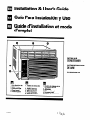 1
1
-
 2
2
-
 3
3
-
 4
4
-
 5
5
-
 6
6
-
 7
7
-
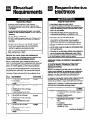 8
8
-
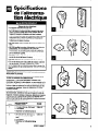 9
9
-
 10
10
-
 11
11
-
 12
12
-
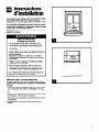 13
13
-
 14
14
-
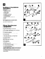 15
15
-
 16
16
-
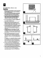 17
17
-
 18
18
-
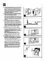 19
19
-
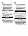 20
20
-
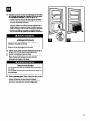 21
21
-
 22
22
-
 23
23
-
 24
24
-
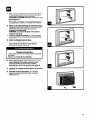 25
25
-
 26
26
-
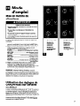 27
27
-
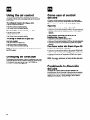 28
28
-
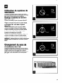 29
29
-
 30
30
-
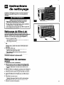 31
31
-
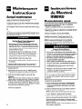 32
32
-
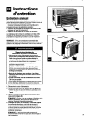 33
33
-
 34
34
-
 35
35
-
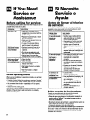 36
36
-
 37
37
-
 38
38
-
 39
39
-
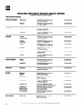 40
40
-
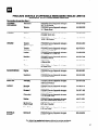 41
41
-
 42
42
-
 43
43
-
 44
44


Whirlpool AR1800XA0 El manual del propietario
- Tipo
- El manual del propietario
en otros idiomas
- français: Whirlpool AR1800XA0 Le manuel du propriétaire
- English: Whirlpool AR1800XA0 Owner's manual
Artículos relacionados
-
Whirlpool ACM184XA0 Manual de usuario
-
-
-
-
Whirlpool ACM184XE1 Manual de usuario
-
-
-
-
-
