
E SERIES BUILT-IN OVENS
INSTALLATION INSTRUCTIONS
INSTRUCCIONES DE INSTALACIÓN
INSTRUCTIONS D’INSTALLATION
ISTRUZIONI PER L’INSTALLAZIONE
INSTALLATIONSANWEISUNGEN

ENGLISH 4
ESPÃNOL 22
FRANÇAIS 40
ITALIANO 58
DEUTSCH 76
3

As you follow these instruc tions, you will
notice WARNING and CAUTION symbols.
This blocked information is impor tant for the
safe and efficient installation of Wolf equip-
ment. There are two types of potential
hazards that may occur during installation.
Another footnote we would like to identify is
IMPORTANT NOTE: This highlights informa-
tion that is especially relevant to a problem-
free installation.
signals a situation where minor injury or
product damage may occur if you do not
follow instructions.
states a hazard that may cause serious
injury or death if precautions are not
followed.
WOLF
®
is a registered trademark of Wolf Appliance, Inc.
CONTACT
INFORMATION
Website:
wolfappliance.com
ORIGINAL
INSTRUCTIONS

INSTALLATION REQUIREMENTS
IMPORTANT NOTE: This installation must
be completed by a qualified technician.
IMPORTANT NOTE:
Save these Installation
Instructions for the local inspector’s use.
Please read the entire Installation Instruc-
tions prior to installation.
Installer:
please retain these instructions
for local inspector’s reference, then leave
them with the homeowner.
Homeowner:
please read and keep these
instructions for future reference and be sure
to read the entire Use & Care Information
prior to use.
IMPORTANT NOTE:
This appliance must be
installed in accordance with all local codes.
The correct voltage, frequency and amperage
must be supplied to the appliance from a dedi-
cated, grounded circuit which is protected by a
properly sized circuit breaker or time delay
fuse. The proper voltage, frequency, and
amperage ratings are listed on the product
rating plate.
Record the model and serial numbers before
installing the built-in oven. Both numbers are
listed on the rating plate, located on the right
side of the oven trim, directly above the door.
Open the oven door to view the rating plate.
Refer to the illustration below.
WOLF E SERIES BUILT-IN OVENS
SITE PREPARATION
IMPORTANT NOTE:
A minimum 610 mm of
usable cabinet depth is required, or the back
panel of the cabinet may need to be removed
for proper installation. A minimum 635 mm of
usable cabinet depth is required for a flush
inset installation. The electrical box must be
flush with the back panel of the cabinet.
The installation opening must have a flat, level
base platform to support the oven. Single
ovens require a minimum base support of
113 kg and double ovens require a minimum
base support of 181 kg.
IMPORTANT NOTE:
Wolf built-in ovens are
designed and agency approved for installation
with Wolf cooktops, microwaves and warming
drawers only. The nominal width of the built-in
oven should match the nominal width of the
cooktop. A built-in oven cannot be installed
below a Wolf rangetop.
RATING PLATE
INFORMATION
Model Number
Serial Number
Rating plate location
Location
of rating
plate
5

WOLF E SERIES BUILT-IN OVENS
E SERIES BUILT-IN SINGLE OVENS
IMPORTANT NOTE:
A minimum 610 mm of
usable cabinet depth is required, or the back
panel of the cabinet may need to be removed
for proper installation. A minimum 635 mm of
usable cabinet depth is required for a flush
inset installation. The electrical box must be
flush with the back panel of the cabinet.
For ease of installation, Wolf recommends
using 838 mm wide cabinets with the E Series
single oven. A minimum 838 mm wide cabinet
is required for a flush inset installation. The
cabinet base platform must be able to support
113 kg.
Refer to the following illustrations for overall
dimensions, installation specifications and
electrical location for the E Series single oven.
The E Series single oven requires a grounded
3-wire 220-240 V AC, 50 Hz electrical supply.
Refer to Electrical Requirements on page 16.
The oven is not supplied with an electrical
plug.
IMPORTANT NOTE:
Unless you are using
cabinets deeper than 610 mm for a standard
installation or 635 mm for a flush inset installa-
tion, it is recommended that the electrical
supply be placed in an adjacent cabinet.
Choose the location shown in the installation
illustrations on pages 8–9 that best suits your
installation.
603 mm
BEHIND FRAME
708
mm
718 mm
759 mm
603*
mm
CONDUIT
CHANNEL
OPEN OVEN DOOR
559
mm
32 mm
25 mm*
48 mm
48 mm
687
mm
759 mm
67*
mm
*For black glass model, increase dimension by 6 mm.
TOP VIEW
RIGHT SIDE VIEW
OVERALL DIMENSIONS
Unframed Model ICBSO30-2U/S shown.
6

INSTALLATION INSTRUCTIONS
E SERIES BUILT-IN SINGLE OVENS
STANDARD INSTALLATION
IMPORTANT NOTE:
For standard installations,
a minimum 610 mm of usable cabinet depth is
required, or the back panel of the cabinet may
need to be removed for proper installation.
The electrical box must be flush with the back
panel of the cabinet.
For standard installations, the E Series built-in
oven is installed by inserting into cabinetry
from the front. The oven has a face trim on all
four sides and will overlap stiles and rails. The
trim overlaps 3 mm on the bottom, 8 mm on
the top and 19 mm on each side.
FLUSH INSET INSTALLATION
IMPORTANT NOTE:
For flush inset installa-
tions, a minimum 635 mm of usable cabinet
depth is required, 641 mm for black glass
models, or the back panel of the cabinet may
need to be removed for proper installation.
The electrical box must be flush with the back
panel of the cabinet.
The flush inset installation requires the built-in
oven to be recessed into the cabinet. A
minimum 838 mm wide and 635 mm deep
cabinet is needed if you want the front of the
oven to be flush with surrounding cabinetry.
IMPORTANT NOTE:
For flush inset installa-
tions, the inside edges of the rough opening
must be finished, as they will be exposed
when the oven door is open. These edges
should be stained instead of having a lami-
nated surface, to avoid damage from high
temperatures during self-clean.
COMBINATION INSTALLATIONS
The Wolf E Series single oven may be installed
below a Wolf 762 mm induction, electric or gas
cooktop. Unless you are using cabinets deeper
than 610 mm for a standard installation or 635
mm for a flush inset installation, it is recom-
mended that the electrical supply be placed in
the base cabinet to the right of the oven. The E
Series single oven may also be installed below
a Wolf 914 mm induction, electric or gas
cooktop.
A Wolf E Series single oven may be installed
next to another E Series single oven. You must
allow for a 64 mm space between the oven
rough openings. Also, a separate inner wall is
required for each oven between openings.
7

WOLF E SERIES BUILT-IN OVENS
E SERIES BUILT-IN SINGLE OVENS
DIMENSION WILL VARY*
121 mm TYPICAL*
914 mm
FLOOR TO
COUNTERTOP
*Dimension must accommodate height of oven trim.
NOTES: Location of electrical supply within opening may require additional cabinet depth.
Dashed line represents profile of unit.
E
724 mm
OPENING WIDTH
691 mm
OPENING
HEIGHT
610 mm min
OPENING DEPTH
E
127
mm
102
mm
FRONT VIEWSIDE VIEW
STANDARD INSTALLATION
Overall Oven Width 759 mm
Overall Oven Height 708 mm
Overall Oven Depth (behind frame) 603 mm
Open Door Clearance 559 mm
Recommended Cabinet Width 838 mm
Minimum Cabinet Width 762 mm
Minimum Cabinet (Opening) Depth 610 mm
Opening Width 724 mm
Opening Height 691 mm
Minimum Base Support 113 kg
STANDARD INSTALLATION
8

INSTALLATION INSTRUCTIONS
E SERIES BUILT-IN SINGLE OVENS
FLUSH INSET INSTALLATION
Overall Oven Width 759 mm
Overall Oven Height 708 mm
Overall Oven Depth (behind frame) 603 mm
Open Door Clearance 559 mm
Minimum Base Support 113 kg
Minimum Cabinet Width 838 mm
Minimum Flush Inset Depth 635 mm
Opening Width 724 mm
Minimum Flush Inset Width 772 mm
Opening Height 691 mm
Minimum Flush Inset Height 724 mm
FLUSH INSET INSTALLATION
691 mm
OPENING
HEIGHT
724 mm min
FLUSH INSET
HEIGHT
724 mm
OPENING WIDTH
772 mm min
FLUSH INSET WIDTH
22 mm TOP CLEAT
11 mm
BOTTOM CLEAT
SIDE CLEATS
629 mm* min
FLUSH INSET
DEPTH
25 mm*
*For black glass model, increase dimension by 6 mm.
NOTES: Minimum base support 113 kg.
Location of electrical supply within opening may require additional cabinet depth.
Cleats may be visible and should be finished to match cabinetry.
Dashed line represents profile of unit.
FRONT VIEWSIDE VIEW
TOP VIEW
25 mm
SIDE CLEATS
127
mm
102
mm
E
E
E
IMPORTANT
NOTE
For flush inset
installations, the
inside edges of the
rough opening
must be finished,
as they will be
exposed when the
oven door is open.
9

WOLF E SERIES BUILT-IN OVENS
E SERIES BUILT-IN DOUBLE OVENS
IMPORTANT NOTE:
A minimum 610 mm of
usable cabinet depth is required, or the back
panel of the cabinet may need to be removed
for proper installation. A minimum 635 mm of
usable cabinet depth is required for a flush
inset installation. The electrical box must be
flush with the back panel of the cabinet.
For ease of installation, Wolf recommends
using 838 mm wide cabinets with the E Series
double oven. A minimum 838 mm wide
cabinet is required for a flush inset installation.
The cabinet base platform must be able to
support 181 kg.
Refer to the following illustrations for overall
dimensions, installation specifications and
electrical location for the E Series double oven.
The E Series double oven requires a grounded
3-wire 220-240 V AC, 50 Hz electrical supply.
Refer to Electrical Requirements on page 16.
The oven is not supplied with an electrical
plug.
603 mm
BEHIND FRAME
1280
mm
1257
mm
718 mm
759 mm
603*
mm
OPEN OVEN DOOR
TOP VIEW
67*
mm
559
mm
32 mm
25 mm*
48 mm
48 mm
759 mm
CONDUIT
CHANNEL
*For black glass model, increase dimension by 6 mm.
RIGHT SIDE VIEW
OVERALL DIMENSIONS
IMPORTANT NOTE:
Unless you are using
cabinets deeper than 610 mm for a standard
installation or 635 mm for a flush inset installa-
tion, it is recommended that the electrical
supply be placed in an adjacent cabinet.
Choose the location shown in the installation
illustrations on pages 12–13 that best suits
your installation.
Unframed Model ICBDO30-2U/S shown.
10

INSTALLATION INSTRUCTIONS
E SERIES BUILT-IN DOUBLE OVENS
STANDARD INSTALLATION
IMPORTANT NOTE:
For standard installations,
a minimum 610 mm of usable cabinet depth is
required, or the back panel of the cabinet may
need to be removed for proper installation.
The electrical box must be flush with the back
panel of the cabinet.
For standard installations, the E Series built-in
oven is installed by inserting into cabinetry
from the front. The oven has a face trim on all
four sides and will overlap stiles and rails. The
trim overlaps 3 mm on the bottom, 8 mm on
the top and 19 mm on each side.
FLUSH INSET INSTALLATION
IMPORTANT NOTE:
For flush inset installa-
tions, a minimum 635 mm of usable cabinet
depth is required, 641 mm for black glass
models, or the back panel of the cabinet may
need to be removed for proper installation.
The electrical box must be flush with the back
panel of the cabinet.
The flush inset installation requires the built-in
oven to be recessed into the cabinet. A
minimum 838 mm wide and 635 mm deep
cabinet is needed if you want the front of the
oven to be flush with surrounding cabinetry.
IMPORTANT NOTE:
For flush inset installa-
tions, the inside edges of the rough opening
must be finished, as they will be exposed
when the oven doors are open. These edges
should be stained instead of having a lami-
nated surface, to avoid damage from high
temperatures during self-clean.
11

WOLF E SERIES BUILT-IN OVENS
E SERIES BUILT-IN DOUBLE OVENS
1702 mm
TYPICAL*
1260 mm
OPENING
HEIGHT
E
E
E
724 mm
OPENING WIDTH
E
127
mm
102
mm
610 mm min
OPENING DEPTH
*Dimension must accommodate height of oven trim.
NOTES: Location of electrical supply within opening may require additional cabinet depth.
Dashed line represents profile of unit.
FRONT VIEWSIDE VIEW
STANDARD INSTALLATION
Overall Oven Width 759 mm
Overall Oven Height 1280 mm
Overall Oven Depth (behind frame) 603 mm
Open Door Clearance 559 mm
Recommended Cabinet Width 838 mm
Minimum Cabinet Width 762 mm
Minimum Cabinet (Opening) Depth 610 mm
Opening Width 724 mm
Opening Height 1260 mm
Minimum Base Support 181 kg
STANDARD INSTALLATION
12

INSTALLATION INSTRUCTIONS
E SERIES BUILT-IN DOUBLE OVENS
FLUSH INSET INSTALLATION
Overall Oven Width 759 mm
Overall Oven Height 1280 mm
Overall Oven Depth (behind frame) 603 mm
Open Door Clearance 559 mm
Minimum Base Support 181 kg
Minimum Cabinet Width 838 mm
Minimum Flush Inset Depth 635 mm
Opening Width 724 mm
Minimum Flush Inset Width 772 mm
Opening Height 1260 mm
Minimum Flush Inset Height 1294 mm
FLUSH INSET INSTALLATION
1260 mm
OPENING
HEIGHT
1294 mm min
FLUSH INSET
HEIGHT
724 mm
OPENING WIDTH
772 mm min
FLUSH INSET WIDTH
22 mm TOP CLEAT
11 mm
BOTTOM CLEAT
SIDE CLEATS
629 mm* min
FLUSH INSET
DEPTH
25 mm*
*For black glass model, increase dimension by 6 mm.
NOTES: Minimum base support 181 kg.
Location of electrical supply within opening may require additional cabinet depth.
Cleats may be visible and should be finished to match cabinetry.
Dashed line represents profile of unit.
FRONT VIEWSIDE VIEW
TOP VIEW
25 mm
SIDE CLEATS
127
mm
102
mm
E
E
E
1702 mm
TYPICAL
IMPORTANT
NOTE
For flush inset
installations, the
inside edges of the
rough opening
must be finished,
as they will be
exposed when the
oven doors are
open.
13

WOLF E SERIES BUILT-IN OVENS
STANDARD INSTALLATION
OPTIONS
E SERIES BUILT-IN SINGLE OVEN
The Wolf E Series single oven may be installed
in combination with a Wolf convection or non-
convection microwave oven with 762 mm
E Series trim kit, and a Wolf warming drawer
with E Series stainless steel drawer front or
integrated drawer front. Refer to the illustra-
tion below, and pages 6–9 for installation spec-
ifications for E Series single ovens.
Keep in mind that the size of the custom
panel for the warming drawer with integrated
drawer front will vary according to the
specific installation. Refer to the installation
instructions provided with the microwave trim
kit and warming drawer front for detailed
specifications. Dimensions will vary according
to the specific installation.
14

INSTALLATION INSTRUCTIONS
610 mm min
OPENING DEPTH
NOTES: Minimum base support for oven 113 kg.
Location of electrical supply within opening may require additional cabinet depth.
Dashed line represents profile of unit.
FRONT VIEWSIDE VIEW
727 mm
WARMING DRAWER
OPENING WIDTH
724 mm
OVEN OPENING WIDTH
E
E
MICROWAVE
OPENING
691 mm
38 mm
min
232 mm
19 mm
min
A
NTI-TIP
E
E
127
mm
102
mm
STANDARD INSTALLATION
Single oven installed with convection microwave with 762 mm E Series trim and warming drawer with
E Series stainless steel drawer front.
15

WOLF E SERIES BUILT-IN OVENS
IMPORTANT
NOTE
Be aware of local
codes and ordi-
nances when
installing your
service.
E SERIES SINGLE OVENS
Required power supply:
Single phase: 220-240V AC; 50 Hz
3phase: 380-415V AC; 50 Hz
Maximum connected load:
Single phase: 4.4 kW
3phase: 4.4 kW
Total amps:
Single phase: 19 amps
3phase: 19 amps
E SERIES DOUBLE OVENS
Required power supply:
Single phase: 220-240V AC; 50 Hz
3phase: 380-415V AC; 50 Hz
Maximum connected load:
Single phase: 7.4 kW
3phase: 5.1 kW
Total amps:
Single phase: 32 amps
3phase: 22 amps
Refer to the wiring diagram showing the
connections for each lead to the terminal box
on the unit.
ELECTRICAL REQUIREMENTS
The complete appliance must be properly
grounded at all times when electrical
power is applied.
NOTE: Improper connection can result in
a fire hazard.
Before obtaining access to terminals, all
supply circuits must be disconnected.
Verify that power is disconnected from
the electrical box before proceeding.
Open the terminal box to expose the screws
with corresponding numbers. Run the cord
through the strain relief hole and into the
terminal box.
For Single Phase Install (Line, Neutral,
Ground):
Loosen the 1, 5, and ground screws.
Attach the Neutral wire to the number 5
position. Line should be attached to the 1
postion and attach the ground to the corre-
sponding ground screw.
For 3phase Install (L1, L2, L3, Neutral,
Ground):
Loosen the 1, 2, 3 and remove the
copper bars. Loosen 5 and ground screws.
Attach L1 to position 1. L2 to position 2. L3 to
position 3. Neutral wire to position 5 and attach
the ground to the corresponding ground screw.
After tightening the screws, tighten down the
cord strain relief and close the cover to the
terminal box without pinching any of the wires.
IMPORTANT NOTE:
Connection of this appli-
ance should be through a fused connection
unit or a suitable isolator, which complies with
national and local safety regulations. The
on/off switch should be easily accessible after
the appliance has been installed. If the switch
is not accessible after installation (depending
on country) an additional means of disconnec-
tion must be provided for all poles of the
power supply. When switched off there must
be an all pole contact gap of 3 mm in the
isolator switch. This 3 mm contact disconnect
gap must apply to any isolator switch, fuses
and/or relays according to EN60335.
16
Copper bars must be removed from posi-
tions 1, 2, and 3 when connecting to
3phase power.
N
L1
Single phase wiring diagram
N
L1
L2
L3
3phase wiring diagram
3N
˜
˜

INSTALLATION INSTRUCTIONS
ELECTRICAL REQUIREMENTS
With the oven positioned directly in front of
the cabinet opening, feed a minimum 105°C
rated cord attached to the oven terminal box
through the opening in the cabinet platform
(where applicable). Then, depending upon
local codes, utilize one of the following tech-
niques to connect the appliance to the electri-
cal power supply.
INSTALLING THE OVEN
UNPACK THE OVEN
Cut the plastic straps and remove the two
V-boards. Remove the four top foam corners
and the corner posts. Remove the carton
sleeve by lifting the sleeve up and over the
appliance.
Remove all oven racks, oven rack guides and
accessories from inside the oven cavity. For
the double oven, be sure to do this for both
the upper and lower ovens.
Remove the four bottom corners. Use caution
as the oven is not mounted to the shipping
base. Keep the bottom foam in place when
moving or carting the oven. The bottom foam
also protects the factory-installed trim.
IMPORTANT NOTE:
Before moving the oven,
protect any finished flooring with appropriate
materials to avoid damage to the floor.
Remove and discard all packing materials,
including cardboard and tape on the outside of
the oven and inside the oven cavity.
Oven is not mounted to the shipping
base. Do not remove banding until the
oven is at the point of installation.
Do not remove the bottom foam until
oven has been positioned next to the
installation opening.
Do not lift the unit by the oven door
handle(s). This will damage the oven door
and hinges.
17

WOLF E SERIES BUILT-IN OVENS
POSITION THE OVEN
Holding the oven by the upper edge and
bottom side of the oven chassis, carefully lift
the oven up to the cabinet opening.
Resting the oven on the cabinet base platform,
slide the oven into the opening until it is
approximately 152 mm from full insertion. If
applicable, ensure that the installer supplied
cable slides through the opening in the cabinet
platform as the oven is slid into place.
IMPORTANT NOTE:
The installer supplied
cable must be placed in the recessed area
located along the right rear vertical edge of the
oven. Make sure that the cable is not trapped
between the oven and the inner cabinet wall.
Do not block the oven air exhaust located
at the bottom of the oven. Blocking the
exhaust may cause cabinet damage and
poor baking performance.
The oven is very heavy—use caution
when lifting. It is recommended that two
people lift and position the oven into the
opening. Wear gloves to protect hands
from any sharp edges.
INSTALLING THE OVEN
OVEN DOOR REMOVAL
To reduce the weight of the oven and ease
installation, removal of the oven door(s) is an
option.
To Remove Oven Door:
Open oven door all the way.
Flip down the hinge latch on each side.
Close the oven door as far as it will shut.
While holding the oven door on each side
with both hands, lift the oven door up.
Continue to push the oven door closed and
pull it away from the oven frame.
To Reinstall Oven Door:
Insert both hanger arms into the oven
frame openings.
Open the oven door. You should hear a
”click” as the door is set into place.
Move the hinge levers back to the locked
position. Ensure that the door is free to
open and close. If not, repeat the removal
and reinstallation procedures.
18

INSTALLATION INSTRUCTIONS
INSTALLING THE OVEN
MOUNT OVEN TO CABINETRY
Once the oven is fully inserted into the cabinet
opening, locate the mounting holes on the
oven side trim. There will be four mounting
holes for a single oven and six for a double
oven. Refer to the illustration below. Use a
2 mm drill bit to drill pilot holes into the
cabinet. Use the provided wood screws to
secure the oven to the cabinet through the
oven mounting holes.
OVEN OPERATION
IMPORTANT NOTE:
Prior to operating the
oven, be sure to read the entire Wolf E Series
Built-In Ovens Use & Care Information
included with the oven for important safety
information.
Unpack the box containing the oven compo-
nents found in each oven cavity. Install the
oven rack guides onto the shoulder screws
located on the interior side walls of the oven.
Slide the oven racks onto the support racks
within the oven. There are three racks per
oven. Place the broiler pan and grid on a rack
within the oven, if desired.
Turn on the power supply to the oven. Set the
time of day by pressing the
SET CLOCK
touch pad, input the desired time by using the
number pads, then touch
ENTER
.
Select any of the ten cooking modes on the
control panel. Verify that the oven is coming
up to temperature. For the double oven, be
sure to verify operation of both ovens.
IMPORTANT NOTE:
A small amount of smoke
and odor may be noticed during the initial
break-in period. Refer to the Use & Care
Information for additional information.
Failure to install the mounting screws
may cause the oven to move or tip
forward during use. This may result in
damage to the oven or personal injury.
Location of mounting holes
19

CONTACT
INFORMATION
Website:
wolfappliance.com
TROUBLESHOOTING
IMPORTANT NOTE:
If the built-in oven does
not operate properly, follow these trouble-
shooting steps:
Verify that power is being supplied to the
oven.
Check the electrical connections to ensure
that the installation has been completed
correctly.
Follow troubleshooting procedures as
described in the Wolf E Series Built-In
Ovens Use & Care Information.
If the oven still does not work, contact a
Wolf authorized service center. Do not
attempt to repair the oven yourself. Wolf
is not responsible for service required to
correct a faulty installation.
WIRING DIAGRAM
The wiring diagram covering the control circuit
is located on the top of the oven in a sealed
plastic bag.
WOLF E SERIES BUILT-IN OVENS
IF YOU NEED SERVICE
For service in your area, contact either your
Wolf dealer or visit the Showroom Locator
section of our website, wolfappliance.com
to find the regional distributor by country.
When calling for service, you will need the
built-in oven model and serial numbers.
Both numbers are listed on the product
rating plate, located on the right side of the
oven trim, directly above the door. Open
the oven door to view the rating plate.
Refer to the illustration on page 5 for
location of the rating plate.
20

The information and images in this book are
the copyright property of Wolf Appliance, Inc.,
an affiliate of Sub-Zero, Inc. Neither this book
nor any information or images contained herein
may be copied or used in whole or in part
without the express written permission of Wolf
Appliance, Inc., an affiliate of Sub-Zero, Inc.
©Wolf Appliance, Inc. all rights reserved.
21

Cuando consulte las instrucciones que
aparecen en esta guía, encontrará símbolos
de AVISO y PRECAUCIÓN. Esta información
en recuadros es importante para instalar el
equipo de Wolf de forma segura y eficaz.
Existen dos tipos de posibles riesgos que
pueden producirse durante una instalación.
Otro tipo de anotación que es importante
resaltar es la que se incluye en NOTA
IMPORTANTE: En esta nota se resalta la
información que resulta especialmente
importante para que la instalación se
realice sin problemas.
PRECAUCI
Ó
N
indica una situación en la que se pueden
sufrir heridas leves o provocar daños
secundarios al producto si no se siguen
las instrucciones.
AVISO
indica peligro de que se produzcan
heridas personales graves o incluso puede
provocar la muerte si no se siguen las
precauciones especificadas.
WOLF
®
es una marca comercial registrada de Wolf Appliance, Inc.
INFORMACIÓN
DE CONTACTO
Página Web:
www.sub-zero.eu.com
INSTRUCCIONES
GENERALES

23
REQUISITOS DE INSTALACIÓN
NOTA IMPORTANTE: Esta instalación debe ser
realizada por un técnico cualificado.
NOTA IMPORTANTE:
Guarde estas instrucciones
de instalación para que el inspector local pueda
utilizarlas.
Lea las instrucciones de instalación antes de
llevar a cabo la instalación.
Instalador:
guarde estas instrucciones para
que el inspector local pueda utilizarlas como
referencia y, a continuación, entréguelas al
propietario del aparato.
Propietario:
lea y guarde estas instrucciones
para que pueda utilizarlas como referencia en
el futuro y asegúrese de leer la guía de uso y
mantenimiento antes de utilizar el aparato.
NOTA IMPORTANTE:
Este aparato debe instalarse
siguiendo todas las normativas nacionales
correspondientes. Se debe aplicar al aparato
el voltaje, la frecuencia y el amperaje adecuados
desde una instalación eléctrica resistente con
toma de tierra protegida por un fusible de retardo.
El voltaje, la frecuencia y el amperaje se muestran
en la placa de datos del producto.
Apunte la referencia del modelo y los números
de serie antes de instalar el horno integrable.
Encontrará estos números en la placa de datos,
situada en el lado derecho del borde del horno,
justo encima de la puerta. Abra la puerta del
horno para verla. Observe la siguiente ilustración.
HORNOS INTEGRABLES SERIE E DE WOLF
PREPARACIÓN DEL
SITIO
NOTA IMPORTANTE:
Es necesario dejar un fondo
mínimo de 610 mm utilizables, si no, podría ser
necesario quitar el panel trasero del armario para
que el horno quede bien instalado. En el caso de
una instalación empotrable, es necesario dejar un
fondo mínimo de 635 mm utilizables. La caja de
conexiones debe empotrarse con el panel trasero
del armario.
La apertura de la instalación debe tener una
plataforma con una superficie nivelada y plana
para aguantar el horno. Los hornos sencillos
necesitan un apoyo de superficie mínimo de
113 kg mientras que los hornos dobles
necesitan que este apoyo sea de 181 kg.
NOTA IMPORTANTE:
Los hornos integrables
Wolf están diseñados y aprobados por el
organismo regulador correspondiente para que
se puedan instalar solamente con placas,
microondas y cajones calentadores de Wolf. El
ancho nominal del horno integrable debe coincidir
con el ancho nominal de la placa. No se puede
instalar un horno integrable debajo de una cocina
de gas de Wolf.
INFORMACIÓN
DE LA PLACA
DE DATOS
Referencia del
modelo
Número de serie
Ubicación de la placa de datos
Ubicación
de la
placa de
datos

603 mm
DETRÁS DEL MARCO
708
mm
718 mm
759 mm
603*
mm
CANAL DEL
CONDUCTO PARA
CABLES
PUERTA DEL HORNO ABIERTA
559
mm
32 mm
25 mm*
48 mm
48 mm
687
mm
759 mm
67*
mm
*Para el modelo en vidrio negro, aumente el tamaño en 6 mm.
VISTA SUPERIOR
VISTA LATERAL DERECHA
24
HORNOS INTEGRABLES SERIE E DE WOLF
HORNOS SENCILLOS INTE-
GRABLES
SERIE E
NOTA IMPORTANTE:
Es necesario dejar un fondo
mínimo de 610 mm utilizables, si no, podría ser
necesario quitar el panel trasero del armario para
que el horno quede bien instalado. En el caso de
una instalación empotrable, es necesario dejar un
fondo mínimo de 635 mm utilizables. La caja de
conexiones debe empotrarse con el panel trasero
del armario.
Para facilitar la instalación, Wolf recomienda
utilizar un armario con un ancho de 838 mm
para el horno sencillo Serie E. En el caso de
una instalación empotrable, es necesario que
el armario tenga 838 mm de ancho como mínimo.
La plataforma base del armario debe aguantar un
peso de 113 kg.
Vea las siguientes ilustraciones para conocer las
medidas totales, las especificaciones de instalación
y la ubicación de los componentes eléctricos del
horno sencillo de la Serie E.
El horno simple de la serie E necesita un sumin-
istro eléctrico trifásico con toma a tierra de 220-
240 V CA, 50 Hz. Consulte la sección Requisitos
eléctricos en la página 34. El horno no se entrega
con un enchufe eléctrico.
NOTA IMPORTANTE:
A menos que utilice armarios
con un fondo superior a 610 mm para una
instalación estándar o con un fondo superior a 635
mm para una instalación empotrable, se recomienda
que la toma eléctrica se coloque en un armario
contiguo. Elija la ubicación entre las que se
muestran en las ilustraciones de instalación en las
páginas 26-27 que mejor se adapte a su instalación.
MEDIDAS TOTALES

25
INSTRUCCIONES DE INSTALACIÓN
HORNOS SENCILLOS INTE-
GRABLES
SERIE E
INSTALACIÓN ESTÁNDAR
NOTA IMPORTANTE:
Para las instalaciones
estándar, es necesario dejar un fondo mínimo
de 610 mm utilizables, si no, podría ser necesario
quitar el panel trasero del armario para que
el aparato quede bien instalado. La caja de
conexiones debe empotrarse con el panel
trasero del armario.
Para las instalaciones estándar, el horno integrable
Serie E queda instalado al insertarlo en el armario
desde la parte delantera. El horno tiene un
contramarco frontal en cada uno de los cuatro
lados que va superpuesto sobre los raíles y
montantes. El contramarco sobresale 3 mm en
la parte inferior, 8 mm en la parte superior y 19
mm a cada uno de los lados.
INSTALACIÓN EMPOTRABLE
NOTA IMPORTANTE:
Para las instalaciones empo-
trables, es necesario dejar un fondo mínimo de
635 mm utilizables y de 641 mm para los modelos
en vidrio negro; si no, podría ser necesario quitar
el panel trasero del armario para que el aparato
quede bien instalado. La caja de conexiones debe
empotrarse con el panel trasero del armario.
La instalación empotrable exige que el horno
integrable quede bien acoplado dentro del
armario. Si desea que el frente del horno quede
empotrado respecto al mobiliario circundante,
necesitará un mueble con un ancho mínimo de
838 mm y un fondo mínimo de 635 mm.
NOTA IMPORTANTE:
En las instalaciones
empotrables, los bordes internos de la cavidad
deben estar acabados, ya que quedarán expuestos
cuando la puerta del horno esté abierta. Estos
bordes deberían estar teñidos en vez de tener
una superficie laminada con el fin de evitar que
las altas temperaturas de la limpieza automática
los dañen.
INSTALACIONES COMBINADAS
Los hornos sencillos Serie E de Wolf se pueden
instalar debajo de una vitrocerámica, una placa
de gas o de inducción de 762 mm de Wolf. A
menos que utilice armarios con un fondo superior
a 610 mm para una instalación estándar o con un
fondo superior a 635 mm para una instalación
empotrable, se recomienda que la toma eléctrica
se coloque en el armario base situado a la derecha
del horno. Los hornos sencillos Serie E también se
pueden instalar debajo de una vitrocerámica, una
placa de gas o de inducción de 914 mm de Wolf.
Además, existe la posibilidad de instalar un horno
sencillo Serie E de Wolf al lado de otro horno
sencillo Serie E. Debe dejar un espacio de 64 mm
entre las cavidades del horno. También es
necesario dejar una pared interior separada
entre las cavidades de cada uno de los hornos.

26
HORNOS INTEGRABLES SERIE E DE WOLF
HORNOS SENCILLOS INTE-
GRABLES
SERIE E
LA MEDIDA PUEDE VARIAR*
121 mm TÍPICO*
914 mm
DEL SUELO
A LA ENCIMERA
*Las medidas deben coincidir con la altura del borde del horno.
NOTAS: la ubicación de la toma eléctrica en la cavidad puede exigir un armario de mayor profundidad.
Las líneas discontinuas representan el perfil de la unidad.
E
724 mm
ANCHURA DE LA CAVIDAD
691 mm
ALTURA DE
LA CAVIDAD
610 mm min
FONDO DE LA CAVIDAD
E
127
mm
102
mm
VISTA FRONTALVISTA LATERAL
INSTALACIÓN ESTÁNDAR
Anchura total del horno 759 mm
Altura total del horno 708 mm
Fondo total del horno (marco posterior) 603 mm
Margen de apertura de la puerta 559 mm
Anchura del armario recomendada 838 mm
Anchura mínima del mueble 762 mm
Fondo mínimo del armario (apertura) 610 mm
Anchura de la cavidad 724 mm
Altura de la cavidad 691 mm
Soporte mínimo de la base 113 kg
INSTALACIÓN ESTÁNDAR

27
INSTRUCCIONES DE INSTALACIÓN
HORNOS SENCILLOS INTE-
GRABLES
SERIE E
INSTALACIÓN EMPOTRABLE
Anchura total del horno 759 mm
Altura total del horno 708 mm
Fondo total del horno (marco posterior) 603 mm
Margen de apertura de la puerta 559 mm
Soporte mínimo de la base 113 kg
Anchura mínima del mueble 838 mm
Fondo mínimo de
instalación empotrable 635 mm
Anchura de la cavidad 724 mm
Anchura mínima de
instalación empotrable 772 mm
Altura de la cavidad 691 mm
Altura mínima de
instalación empotrable 724 mm
INSTALACIÓN EMPOTRABLE
691 mm
ALTURA DE
LA CAVIDAD
724 mm min
ALTURA
DE
INSTALACIÓN
EMPOTRABLE
724 mm
ANCHURA DE LA CAVIDAD
772 mm min
ANCHURA DE INSTALACIÓN
EMPOTRABLE
22 mm
LISTÓN SUPERIOR
11 mm
LISTÓN
INFERIOR
LISTONES
LATERALES
629 mm* min
FONDO DE
INSTALACIÓN
EMPOTRABLE
25 mm*
*Para el modelo en vidrio negro, aumente el tamaño en 6 mm.
NOTAS: Soporte mínimo de la base 113 kg.
La ubicación de la toma eléctrica en la cavidad puede exigir un armario de mayor profundidad.
Los listones pueden ser visibles y deberán acabarse para que coincidan con los muebles.
Las líneas discontinuas representan el perfil de la unidad.
VISTA FRONTALVISTA LATERAL
VISTA
SUPERIOR
25 mm
LISTONES
LATERALES
127
mm
102
mm
E
E
E
NOTA
IMPORTANTE
En las instalaciones
empotrables, los
bordes internos de la
cavidad deben estar
acabados, ya que
quedarán expuestos
cuando la puerta del
horno esté abierta.

28
HORNOS INTEGRABLES SERIE E DE WOLF
HORNOS DOBLES INTEGRABLES
SERIE E
NOTA IMPORTANTE:
Es necesario dejar un fondo
mínimo de 610 mm utilizables, si no, podría ser
necesario quitar el panel trasero del armario para
que el horno quede bien instalado. En el caso de
una instalación empotrable, es necesario dejar un
fondo mínimo de 635 mm utilizables. La caja de
conexiones debe empotrarse con el panel trasero
del armario.
Para facilitar la instalación, Wolf recomienda
utilizar un armario con un ancho de 838 mm
para el horno doble Serie E. En el caso de una
instalación empotrable, es necesario que el
armario tenga 838 mm de ancho como mínimo.
La plataforma base del armario debe aguantar un
peso de 181 kg.
Vea las siguientes ilustraciones para conocer las
medidas totales, las especificaciones de instalación
y la ubicación de los componentes eléctricos del
horno doble de la Serie E.
El horno doble de la serie E necesita un suministro
eléctrico trifásico con toma a tierra de 220-240 V
CA, 50 Hz. Consulte la sección Requisitos eléctricos
en la página 34. El horno no se entrega con un
enchufe eléctrico.
603 mm
DETRÁS DEL MARCO
1280
mm
1257
mm
718 mm
759 mm
603*
mm
PUERTA DEL HORNO ABIERTA
VISTA SUPERIOR
67*
mm
559
mm
32 mm
25 mm*
48 mm
48 mm
759 mm
CANAL DEL
CONDUCTO
PARA CABLES
*Para el modelo en vidrio negro, aumente el tamaño en 6 mm.
VISTA LATERAL DERECHA
MEDIDAS TOTALES
NOTA IMPORTANTE:
A menos que utilice
armarios con un fondo superior a 610 mm para
una instalación estándar o con un fondo superior
a 635 mm para una instalación empotrable, se
recomienda que la toma eléctrica se coloque en
un armario contiguo. Elija la ubicación entre las
que se muestran en las ilustraciones de instalación
en las páginas 30-31 que mejor se adapte a su
instalación.
Se muestra el modelo ICBDO30-2U/S sin marco

29
INSTRUCCIONES DE INSTALACIÓN
HORNOS DOBLES INTEGRABLES
SERIE E
INSTALACIÓN ESTÁNDAR
NOTA IMPORTANTE:
Para las instalaciones
estándar, es necesario dejar un fondo mínimo
de 610 mm utilizables, si no, podría ser necesario
quitar el panel trasero del armario para que
el aparato quede bien instalado. La caja de
conexiones debe empotrarse con el panel
trasero del armario.
Para las instalaciones estándar, el horno integrable
Serie E queda instalado al insertarlo en el armario
desde la parte delantera. El horno tiene un
contramarco frontal en cada uno de los cuatro
lados que va superpuesto sobre los raíles y
montantes. El contramarco sobresale 3 mm en
la parte inferior, 8 mm en la parte superior y 19
mm a cada uno de los lados.
INSTALACIÓN EMPOTRABLE
NOTA IMPORTANTE:
Para las instalaciones empo-
trables, es necesario dejar un fondo mínimo de
635 mm utilizables y de 641 mm para los modelos
en vidrio negro; si no, podría ser necesario quitar
el panel trasero del armario para que el aparato
quede bien instalado. La caja de conexiones debe
empotrarse con el panel trasero del armario.
La instalación empotrable exige que el horno
integrable quede bien acoplado dentro del
armario. Si desea que el frente del horno quede
empotrado respecto al mobiliario circundante,
necesitará un mueble con un ancho mínimo de
838 mm y un fondo mínimo de 635 mm.
NOTA IMPORTANTE:
En las instalaciones
empotrables, los bordes internos de la cavidad
deben estar acabados, ya que quedarán expuestos
cuando las puertas del horno estén abiertas. Estos
bordes deberían estar teñidos en vez de tener
una superficie laminada con el fin de evitar que
las altas temperaturas de la limpieza automática
los dañen.

30
HORNOS INTEGRABLES SERIE E DE WOLF
HORNOS DOBLES INTEGRABLES
SERIE E
1702 mm
TÍPICO*
1260 mm
ALTURA DE
LA CAVIDAD
E
E
E
724 mm
ANCHURA DE LA CAVIDAD
E
127
mm
102
mm
610 mm min
FONDO DE LA CAVIDAD
*
Las medidas deben coincidir con la altura del borde del horno.
NOTAS: la ubicación de la toma eléctrica en la cavidad puede exigir un armario de mayor profundidad.
Las líneas discontinuas representan el perfil de la unidad.
VISTA FRONTALVISTA LATERAL
INSTALACIÓN ESTÁNDAR
Anchura total del horno 759 mm
Altura total del horno 1.280 mm
Fondo total del horno (marco posterior) 603 mm
Margen de apertura de la puerta 559 mm
Anchura del armario recomendada 838 mm
Anchura mínima del mueble 762 mm
Fondo mínimo del armario (apertura) 610 mm
Anchura de la cavidad 724 mm
Altura de la cavidad 1.260 mm
Soporte mínimo de la base 181 kg
INSTALACIÓN ESTÁNDAR

31
INSTRUCCIONES DE INSTALACIÓN
HORNOS DOBLES INTEGRABLES
SERIE E
INSTALACIÓN EMPOTRABLE
Anchura total del horno 759 mm
Altura total del horno 1.280 mm
Fondo total del horno (marco posterior) 603 mm
Margen de apertura de la puerta 559 mm
Soporte mínimo de la base 181 kg
Anchura mínima del mueble 838 mm
Fondo mínimo de
instalación empotrable 635 mm
Anchura de la cavidad 724 mm
Anchura mínima de
instalación empotrable 772 mm
Altura de la cavidad 1.260 mm
Altura mínima de
instalación empotrable 1.294 mm
INSTALACIÓN EMPOTRABLE
1260 mm
ALTURA DE
LA CAVIDAD
1294 mm min
ALTURA DE
INSTALACIÓN
EMPOTRABLE
724 mm
ANCHURA DE LA CAVIDAD
772 mm min
ANCHURA DE
INSTALACIÓN EMPOTRABLE
629 mm* min
FONDO DE
INSTALACIÓN
EMPOTRABLE
25 mm*
*Para el modelo en vidrio negro, aumente el tamaño en 6 mm.
NOTAS: Soporte mínimo de la base 181 kg.
La ubicación de la toma eléctrica en la cavidad puede exigir un armario de mayor profundidad.
Los listones pueden ser visibles y deberán acabarse para que coincidan con los muebles.
Las líneas discontinuas representan el perfil de la unidad.
VISTA FRONTALVISTA LATERAL
VISTA
SUPERIOR
127
mm
102
mm
E
E
E
1702 mm
TÍPICO
22 mm
LISTÓN SUPERIOR
11 mm
LISTÓN
INFERIOR
LISTONES
LATERALES
25 mm
LISTONES
LATERALES
NOTA
IMPORTANTE
En las instalaciones
empotrables, los
bordes internos de
la cavidad deben
estar acabados,
ya que quedarán
expuestos cuando
las puertas del
horno estén
abiertas.

32
HORNOS INTEGRABLES SERIE E DE WOLF
OPCIONES DE INSTALACIÓN
ESTÁNDAR
HORNO SENCILLO INTEGRABLE
SERIE E
El horno sencillo Serie E de Wolf se puede instalar
en combinación con un horno microondas de
ventilación o sin ventilación de Wolf con el kit de
marco de 762 mm de la Serie E, así como con un
cajón calentador de Wolf con el frente de cajón de
acero inoxidable o integrado de la Serie E. Vea la
siguiente ilustración y las páginas 24–27 para
conocer las especificaciones de instalación
de los hornos sencillos de la Serie E.
Recuerde que el tamaño del panel fabricado a
medida para el cajón calentador con frente
integrado puede variar según cada instalación.
Consulte las instrucciones de instalación que
se proporcionan con el kit de marco de horno
microondas o el frente del cajón calentador
si desea obtener información más detallada.
Las medidas pueden variar dependiendo de
cada instalación.

33
610 mm min
FONDO DE LA CAVIDAD
NOTAS: Soporte mínimo de la base para el horno 113 kg.
La ubicación de la toma eléctrica en la cavidad puede exigir un armario de mayor profundidad.
Las líneas discontinuas representan el perfil de la unidad.
VISTA FRONTALVISTA LATERAL
727 mm
FONDO DE APERTURA
DEL CAJÓN CALENTADOR
724 mm
ANCHURA APERTURA
DE HORNO
E
E
CAVIDAD DEL
MICROONDAS
691 mm
3
8 mm
min
232 mm
19 mm
min
ANTIVUELCO
E
E
127
mm
102
mm
INSTALACIÓN ESTÁNDAR
Horno sencillo instalado con horno microondas de ventilación con el marco de la Serie E de 762 mm y el cajón calentador
con el frente de acero inoxidable de la Serie E.
INSTRUCCIONES DE INSTALACIÓN

34
HORNOS INTEGRABLES SERIE E DE WOLF
NOTA
IMPORTANTE
Deberá cumplir la
normativa eléctrica
nacional al instalar
el aparato.
HORNOS SENCILLOS DE LA SERIE E
Alimentación eléctrica requerida:
Monofásica: 220-240 VCA; 50 Hz
Trifásica: 380-415 VCA; 50 Hz
Carga máxima conectada:
Monofásica: 4,4 kW
Trifásica: 4,4 kW
Amperaje total:
Monofásica:
19 amperios
Trifásica:
19 amperios
HORNOS DOBLES DE LA SERIE E
Alimentación eléctrica requerida:
Monofásica: 220-240 VCA; 50 Hz
Trifásica: 380-415 VCA; 50 Hz
Carga máxima conectada:
Monofásica: 7,4 kW
Trifásica: 5,1 kW
Amperaje total:
Monofásica:
32 amperios
Trifásica:
22 amperios
Vea el cuadro de conexiones que muestra las
conexiones de cada cable a la caja de cables
en la unidad.
REQUISITOS ELÉCTRICOS
AVISO
El aparato debe estar conectado a tierra
de manera correcta siempre que esté
conectado a la red eléctrica.
NOTA: Si la conexión no se realiza de
manera correcta, existe riesgo de que se
produzca un incendio.
Antes de tener acceso a los terminales,
se deben desconectar todos los circuitos
de suministro.
AVISO
Compruebe que la unidad está
desconectada de la caja de
conexiones antes de continuar.
Abra la caja de terminales para ver los tornillos
con los números correspondientes. Pase el cable
por el agujero aliviador de tensión e introdúzcalo
en la caja de cables.
Para la instalación monofásica (línea, neutro,
tierra): Afloje los tornillos 1, 5 y el tornillo de
conexión a tierra. Conecte el cable neutro en la
posición número 5. El cable de línea debe conec-
tarse en la posición número 1 y el cable de
conexión a tierra en el tornillo de conexión a
tierra correspondiente.
Para la instalación trifásica (L1, L2, L3, neutro,
tierra): Afloje 1, 2 y 3 y quite las barras de cobre.
Afloje 5 y los tornillos de conexión a tierra. Conecte
L1 a la posición 1. L2 a la posición 2. L3 a la posición
3. El cable neutro a la posición 5 y conecte la tierra al
tornillo de conexión a tierra correspondiente.
Una vez que haya apretado los tornillos, apriete
el aliviador de tensión del cable y cierre la tapa
de la caja de cables asegurándose de que los
cables no quedan enganchados.
NOTA IMPORTANTE:
la conexión de este aparato
debe realizarse a una unidad de conexión con
fusibles o a un aislador adecuado, que cumple con
las normativas de seguridad nacionales y locales.
El interruptor de encendido/apagado debe encon-
trarse en un lugar accesible después de haber
instalado el aparato. Si no es posible acceder al
interruptor después de la instalación (según el
país), se deberá brindar un medio de desconexión
adicional para todos los polos de la alimentación
eléctrica. Al estar desconectado, deberá existir una
separación de contacto entre todos los polos de 3
mm en el interruptor del aislador. Esta separación
de 3 mm de desconexión de los contactos deberá
aplicarse a cualquier interruptor, fusibles o relés
del aislador según la norma EN60335.
AVISO
Las barras de cobre deben quitarse de las
posiciones 1, 2 y 3 al conectar a la corri-
ente trifásica.
N
L1
Diagrama de cableado monofásico
N
L1
L2
L3
Diagrama de cableado trifásico
3N
˜
˜

35
INSTRUCCIONES DE INSTALACIÓN
REQUISITOS ELÉCTRICOS
Con el horno colocado justo delante de la abertura
del armario, introduzca el cable de 105 °C nomi-
nales mínimos conectado a la caja de terminales
del horno a través de la plataforma del armario
(donde proceda). Después, según la normativa
nacional, utilice una de las siguientes técnicas para
conectar el aparato al suministro eléctrico.
INSTALACIÓN DEL HORNO
DESEMBALAJE DEL HORNO
Corte las correas de plástico y retire los dos
esquineros. Quite las cuatro esquinas de espuma
superiores y los postes esquineros. Levante la hoja
de cartón y sáquela por encima del aparato para
retirarla.
Saque del interior del horno todas las bandejas,
las guías de éstas y accesorios. En el caso del
horno doble, asegúrese que saca estos accesorios
de los dos hornos.
Retire las cuatro esquinas inferiores. Tenga
cuidado, ya que el horno no está montado en la
base de envío. Deje la espuma inferior en su lugar
cuando vaya a mover o desplazar el horno en un
carro. La espuma inferior también protege el
contramarco instalado de fábrica.
NOTA IMPORTANTE:
Antes de desplazar el horno,
proteja el acabado del suelo con lo que resulte
adecuado para evitar dañarlo.
Quite y y tire todo el material de embalaje,
incluido el embalaje de cartón y la cinta que
envuelve la parte exterior del horno y el interior
de éste.
PRECAUCI
Ó
N
El horno no está montado sobre la base
de envío. No retire las cintas hasta que
el horno se encuentre en su lugar
de instalación.
PRECAUCI
Ó
N
No retire la espuma inferior hasta que el
horno se haya colocado junto a la
apertura de instalación.
PRECAUCI
Ó
N
No utilice el tirador de la puerta para
levantar el horno. Podría dañar la puerta
y las bisagras del horno.

36
HORNOS INTEGRABLES SERIE E DE WOLF
COLOCACIÓN DEL HORNO
Sujete el horno por el borde superior y el lado
inferior del bastidor y levante el horno con
cuidado hasta la abertura del armario.
Una vez que el horno está apoyado en la
plataforma base del armario, deslícelo en
la abertura hasta que falten 152 mm
aproximadamente para insertarlo por completo.
Si es necesario, asegúrese de que el instalador
ha suministrado el sistema de deslizamiento de
cable a través de la abertura en la plataforma
del armario cuando el horno se desliza y coloca
en su sitio.
NOTA IMPORTANTE:
El cable suministrado por el
instalador debe estar colocado en el área acoplada
situada a lo largo del borde vertical trasero
derecho del horno. Asegúrese de que el cable no
queda atrapado entre el horno y la pared interna
del armario.
PRECAUCI
Ó
N
No bloquee la salida de aire del horno
situada en la parte inferior del horno. Si
se bloquea esta salida de aire, se puede
dañar el armario y el horneado puede
resultar deficiente.
PRECAUCI
Ó
N
El horno pesa mucho—tenga cuidado
al levantarlo. Se recomienda levantarlo
y colocarlo en la abertura entre dos
personas. Utilice guantes para proteger
las manos de los bordes afilados.
INSTALACIÓN DEL HORNO
RETIRADA DE LA PUERTA DEL
HORNO
Para reducir el peso del horno y facilitar su
instalación, puede optar por retirar la(s) puerta(s)
del horno.
Para retirar la puerta del horno:
Abra la puerta del horno por completo.
Gire hacia abajo el pasador de la bisagra
de cada lado.
Cierre la puerta del horno todo lo que pueda.
Mientras sujeta la puerta del horno por ambos
lados con las dos manos, levante la puerta del
horno hacia arriba. Siga empujando la puerta
del horno cerrada y tire de ella para sacarla
del marco del horno.
Para volver a colocar la puerta en el horno:
Inserte los brazos de soporte en las aperturas
del marco del horno.
Abra la puerta del horno. Debería escuchar
un ”clic” cuando la puerta quede colocada
en su sitio.
Mueva las palancas de las bisagras hacia la
posición de bloqueo. Asegúrese de que la
puerta puede abrirse y cerrarse con facilidad.
Si no es así, repita los procedimientos de
retirada y de recolocación.

37
INSTRUCCIONES DE INSTALACIÓN
INSTALACIÓN
DEL HORNO
MONTAJE EN EL MOBILIARIO
Cuando el horno se encuentre totalmente
insertado en la abertura del armario, localice los
agujeros de montaje en el contramarco lateral del
horno. Los hornos sencillos tienen cuatro agujeros
de este tipo mientras que los hornos dobles tienen
seis. Observe la siguiente ilustración. Utilice una
broca de 2 mm para taladrar agujeros guía en
el armario. Utilice los tornillos para madera
proporcionados para fijar el horno al armario
a través de los agujeros de montaje.
FUNCIONAMIENTO DEL HORNO
NOTA IMPORTANTE:
Antes de utilizar el
horno, asegúrese de que lee la guía de uso
y mantenimiento que se facilita con los hornos
empotrables Serie E de Wolf, para conocer la
información de seguridad importante relacionada
con el horno.
Desembale la caja que contiene los componentes
del horno y que se encuentra en el interior del
horno. Instale las guías de las bandejas del horno
sobre los tornillos de resalto situados en las
paredes laterales del interior del horno. Deslice
las bandejas sobre los soportes dentro del horno.
Existen tres bandejas por horno. Si lo desea,
coloque la bandeja para asar y la rejilla en una
bandeja en el horno.
Encienda el suministro eléctrico del horno. Ajuste
la hora del día; para ello pulse el botón
SET
CLOCK
, introduzca la hora deseada con las
teclas numéricas y, después, pulse
ENTER
.
En el panel de mandos, seleccione uno de los diez
modos de cocción. Compruebe que la temperatura
del horno va subiendo. En el caso de un horno
doble, compruebe el funcionamiento en ambos
hornos.
NOTA IMPORTANTE:
Es posible que se produzca
algo de humo y de olor durante el período de
arranque inicial. Consulte la guía de uso y
mantenimiento para obtener más información.
AVISO
Si no se han fijado correctamente los
tornillos de montaje, el horno podría
moverse o inclinarse hacia delante
durante su funcionamiento. Esto podría
provocar daños en el horno o heridas en
el usuario.
Ubicación de los agujeros de montaje

38
INFORMACIÓN
DE CONTACTO
Página Web:
www.sub-zero.eu.com
SOLUCIÓN DE PROBLEMAS
NOTA IMPORTANTE:
Si el horno integrable
no funciona correctamente, siga estos pasos
de localización y solución de problemas:
Compruebe que el horno está conectado a la
red eléctrica.
Compruebe las conexiones eléctricas para
asegurarse de que la instalación se ha llevado
a cabo de manera correcta.
Realice los procedimientos de solución de
problemas tal y como se describe en la guía de
uso y mantenimiento de los hornos integrables
Serie E de Wolf.
Si el horno sigue sin funcionar, póngase en
contacto con el centro de asistencia técnica
de Wolf. No intente realizar usted mismo
ninguna reparación en el horno. Wolf
no se hace responsable de las tareas de
mantenimiento que deban realizarse para
corregir una instalación defectuosa.
CUADRO DE CONEXIONES
El cuadro de conexiones correspondiente
al circuito de control se sitúa en la parte superior
del horno en una bolsa de plástico sellada.
HORNOS INTEGRABLES SERIE E DE WOLF
SI NECESITA ASISTENCIA TÉCNICA
Para buscar el servicio técnico más cercano,
póngase en contacto con su distribuidor
de Wolf o visite la página Web,
www.sub-zero.eu.com, para buscar el
distribuidor más cercano.
Cuando solicite asistencia técnica, deberá tener
localizado el número de serie y el modelo del
horno integrable. Encontrará estos números
en la placa de datos del producto, situada en
la parte derecha del borde del horno, justo
encima de la puerta. Abra la puerta del horno
para verla. Consulte la ilustración de la página
23 para ubicar la placa de datos.

39
La información y las imágenes que se
incluyen en esta guía son propiedad de Wolf
Appliance, Inc., una filial de Sub-Zero, Inc.
Este documento junto con la información y
las imágenes que en él se incluyen no
pueden copiarse ni utilizarse, total ni parcial-
mente, sin el consentimiento por escrito de
Wolf Appliance, Inc., una filial de Sub-Zero,
Inc.
©Wolf Appliance, Inc. se reserva todos los
derechos.

Vous remarquerez tout au long de ce
manuel d’instruc tions les mentions
ATTENTION et MISE EN GARDE destinées à
fournir des recommandations importantes
afin d’assurer la sécurité et
l’efficacité de l’installation de l’équipement
Wolf. Deux types de dangers potentiels
peuvent se présenter pendant l’installation.
De plus, la mention REMARQUE IMPOR-
TANTE met l’accent sur un renseignement
particulièrement important pour assurer
une installation parfaite.
MISE EN GARDE
signale un danger qui pourrait causer
une blessure mineure ou endommager
le produit si vous ne suivez pas
les instructions.
ATTENTION
signale un danger qui pourrait causer des
blessures graves voire fatales si vous ne
prenez pas certaines précautions.
WOLF
®
est une marque déposée de Wolf Appliance, Inc.
CONTACT
Site Internet :
wolfappliance.com
INSTRUCTIONS
D’ORIGINE

41
EXIGENCES RELATIVES
A L’INSTALLATION
REMARQUE IMPORTANTE : L’installation doit
être effectuée par un poseur qualifié.
REMARQUE IMPORTANTE :
Conservez ces
instructions d’installation pour le technicien local.
Veuillez lire les instructions d’installation
dans leur intégralité avant de procéder
à l’installation.
Poseur :
veuillez conserver ces instructions
afin que le technicien puisse s’y reporter, puis
laissez-les au propriétaire.
Propriétaire :
veuillez lire et conserver ces
instructions pour pouvoir vous y reporter
ultérieurement et assurez-vous de lire le Guide
d’utilisation et d’entretien dans son intégralité
avant d’utiliser votre appareil.
REMARQUE IMPORTANTE :
Cet appareil
ménager doit être installé conformément à tous
les codes locaux. La tension, la fréquence et
l’ampérage appropriés doivent être fournis à cet
appareil à partir d’un circuit spécial, mis à la terre
et protégé par un disjoncteur ou un fusible à
fusion temporisée adapté à l’intensité de courant
requise. La tension, la fréquence et l’ampérage
requis sont indiqués sur la plaque des caractéris-
tiques du produit.
Consignez les numéros de modèle et de série
avant d’installer le four encastrable. Ces deux
numéros figurent sur la plaque des caractéris-
tiques du produit située sur le côté droit de la
moulure du four, juste au-dessus de la porte.
Vous devez ouvrir la porte du four pour voir
la plaque des caractéristiques. Reportez-vous
à l’illustration ci-après.
FOURS ENCASTRABLES WOLF SERIE E
PREPARATION DE L’EMPLACEMENT
REMARQUE IMPORTANTE :
Vous devez prévoir
une profondeur utilisable d’élément de cuisine de
610 mm minimum. Sinon, vous devrez peut-être
enlever le panneau arrière de l’élément pour
pouvoir réaliser une installation adéquate. Pour
une installation avec panneau d’affleurement,
la profondeur utilisable d’élément de cuisine
nécessaire est de 635 mm minimum. Le coffret
électrique doit affleurer au panneau arrière de
l’élément de cuisine.
L’ouverture dans laquelle sera insérée le four doit
être pourvue d’une plate-forme plate et de niveau
sur laquelle reposera le four. Cette plate-forme
doit pouvoir supporter un poids minimum de
113 kg pour les fours simples et de 181 kg pour
les fours doubles.
REMARQUE IMPORTANTE :
Les fours
encastrables Wolf sont étudiés et approuvés
pour être installés avec des plaques de cuisson,
des fours micro-ondes ou des tiroirs chauffants
de marque Wolf uniquement. La largeur nominale
du four encastrable devrait correspondre à la
largeur nominale de la plaque de cuisson. Un
four encastrable ne peut pas être installé sous
un entablement Wolf.
INFORMATIONS
FIGURANT SUR
LA PLAQUE DES
CARACTERISTIQUES
Numéro de modèle
Numéro de série
Emplacement de la plaque des
caractéristiques
Emplacement de
la plaque des
caractéristiques

42
FOURS ENCASTRABLES WOLF SERIE E
FOURS ENCASTRABLES
SIMPLES SERIE E
REMARQUE IMPORTANTE :
Vous devez prévoir
une profondeur utilisable d’élément de cuisine
de 610 mm minimum. Sinon, vous devrez
peut-être enlever le panneau arrière de l’élément
pour pouvoir réaliser une installation adéquate.
Pour une installation avec panneau d’affleurement,
la profondeur utilisable d’élément de cuisine
nécessaire est de 635 mm minimum. Le coffret
électrique doit affleurer au panneau arrière de
l’élément de cuisine.
Pour faciliter l’installation, Wolf recommande
d’utiliser des éléments de cuisine de 838 mm
de largeur avec le four simple Série E. Pour une
installation avec panneau d’affleurement, la largeur
minimum d’élément de cuisine nécessaire est de
838 mm. La plate-forme de l’élément de cuisine
doit pouvoir supporter un poids de 113 kg.
Reportez-vous aux figures suivantes pour consulter
les dimensions hors-tout et les spécifications
d’installation et pour repérer l’emplacement des
raccordements électriques du four simple Série E.
Le four simple Série E requiert une alimentation
électrique à trois fils mise à la terre de 220 - 240 V
c.a. et 50 Hz. Reportez-vous à la section Configura-
tion électrique page 52. Le four est fourni sans
prise de courant.
REMARQUE IMPORTANTE :
Il est recommandé
de placer l’alimentation électrique dans un
élément de cuisine adjacent, sauf si vous utilisez
des éléments de cuisine d’une profondeur de plus
de 610 mm pour une installation standard ou de
plus de 635 mm pour une installation avec
panneau d’affleurement. Choisissez dans les
figures pages 44 et 45 l’emplacement le mieux
adapté à votre installation.
603 mm
DERRIERE LE CADRE
708
mm
718 mm
759 mm
603*
mm
PASSAGE
DU CONDUIT
PORTE DE FOUR OUVERTE
559
mm
32 mm
25 mm*
48 mm
48 mm
687
mm
759 mm
67*
mm
*Pour le modèle en verre noir, rallongez de 6 mm.
VUE EN PLAN
VUE COTE DROIT
DIMENSIONS HORS TOUT
Modèle ICBSO30-2U/S sans cadre illustré

43
INSTRUCTIONS D’INSTALLATION
FOURS ENCASTRABLES
SIMPLES
SERIE E
INSTALLATION STANDARD
REMARQUE IMPORTANTE :
Dans le cas des
installations standard, vous devez prévoir une
profondeur utilisable d’élément de cuisine de
610 mm minimum. Sinon, vous devrez peut-être
enlever le panneau arrière de l’élément pour
pouvoir réaliser une installation adéquate. Le
coffret électrique doit affleurer au panneau
arrière de l’élément de cuisine.
De plus, dans le cas des installations standard, le
four encastrable Série E est inséré dans l’élément
de cuisine, de l’avant. Le four est pourvu d’une
moulure frontale sur les quatre côtés qui empiète
sur les montants et les rails. La moulure empiète
de 3 mm sur le bas, de 8 mm sur le dessus et de
19 mm de chaque côté.
INSTALLATION AVEC PANNEAU
D’AFFLEUREMENT
REMARQUE IMPORTANTE :
Dans le cas des
installations avec panneau d'affleurement, vous
devez prévoir une profondeur utilisable d'élément
de cuisine de 635 mm minimum, 641 mm pour les
modèles en verre noir. Sinon, vous devrez peut-
être enlever le panneau arrière de l'élément pour
pouvoir réaliser une installation adéquate. Le
coffret électrique doit affleurer au panneau arrière
de l’élément de cuisine.
De plus, dans le cas d’une installation avec
panneau d’affleurement, le four doit être encastré
dans l’élément de cuisine. Un élément de cuisine
d’une largeur minimum de 838 mm et d’une
profondeur minimum de 635 mm est requis si
vous souhaitez que la façade du four affleure
aux éléments de cuisine adjacents.
REMARQUE IMPORTANTE :
L’installation avec
panneau d’affleurement exige que les bords
intérieurs de l’ouverture soient finis car ils seront
visibles lorsque la porte du four sera ouverte.
Afin d’éviter les dommages causés par les
températures élevées pendant l’autonettoyage
du four, ces bords devraient être teintés plutôt
que laminés.
INSTALLATIONS COMBINEES
Il est possible d’installer un four simple Wolf
Série E sous une plaque de cuisson à induction,
électrique ou au gaz Wolf de 762 mm. Il est
recommandé de placer l’alimentation électrique
dans un élément de cuisine inférieur, à droite du
four, sauf si vous utilisez des éléments de cuisine
d’une profondeur de plus de 610 mm pour une
installation standard ou de plus de 635 mm pour
une installation avec panneau d’affleurement. Il
est possible d’installer un four simple Wolf Série E
sous une plaque de cuisson à induction, électrique
ou au gaz Wolf de 914 mm.
Vous pouvez également installer deux fours
simples Wolf Série E côte à côte. Vous devez
alors prévoir un espace de 64 mm entre les
ouvertures ménagées pour les fours. De plus,
un mur intérieur distinct est requis pour chaque
four entre les ouvertures.

44
Largeur minimum de
l’élément de cuisine 762 mm
Profondeur minimum de
l’élément de cuisine (ouverture) 610 mm
Largeur d’ouverture 724 mm
Hauteur d’ouverture 691 mm
Capacité minimum de
support de la base 113 kg
FOURS ENCASTRABLES WOLF SERIE E
FOURS ENCASTRABLES
SIMPLES SERIE E
LES DIMENSIONS VARIERONT*
121 mm EN GÉNÉRAL*
914 mm
DU SOL
AU PLAN
DE TRAVAIL
*Les dimensions doivent laisser suffisamment d'espace pour la moulure du four.
REMARQUES : L'emplacement de l'alimentation électrique dans l'ouverture peut exiger une profondeur d'élément de cuisine plus importante.
La ligne en pointillés représente le contour de l'appareil.
E
724 mm
LARGEUR D'OUVERTURE
691 mm
HAUTEUR
D'OUVERTURE
610 mm min
PROFONDEUR
D'OUVERTURE
E
127
mm
102
mm
VUE DE FACEVUE LATERALE
INSTALLATION STANDARD
Largeur hors tout du four 759 mm
Hauteur hors tout du four 708 mm
Profondeur hors tout du four
(derrière le cadre) 603 mm
Dégagement de la porte du four 559 mm
Largeur d’élément de
cuisine recommandée 838 mm
INSTALLATION STANDARD

45
INSTRUCTIONS D’INSTALLATION
FOURS ENCASTRABLES
SIMPLES
SERIE E
INSTALLATION AVEC PANNEAU
D’AFFLEUREMENT
Largeur hors tout du four 759 mm
Hauteur hors tout du four 708 mm
Profondeur hors tout du four
(derrière le cadre) 603 mm
Dégagement de la porte du four 559 mm
Capacité minimum de support
de la base 113 kg
Largeur minimum de
l’élément de cuisine 838 mm
Profondeur minimum du
panneau d’affleurement 635 mm
Largeur d’ouverture 724 mm
Largeur minimum du
panneau d’affleurement 772 mm
Hauteur d’ouverture 691 mm
Hauteur minimum du
panneau d’affleurement 724 mm
INSTALLATION AVEC PANNEAU D’AFFLEUREMENT
691 mm
HAUTEUR
D'OUVERTURE
724 mm min
HAUTEUR
DU PANNEAU
D’AFFLEUREMENT
724 mm
LARGEUR D'OUVERTURE
772 mm min
LARGEUR DU PANNEAU
D’AFFLEUREMENT
22 mm
TASSEAU
SUPÉRIEUR
11 mm
TASSEAU
INFÉRIEUR
TASSEAUX
LATÉRAUX
629 mm* min
HAUTEUR DU
PANNEAU
D’AFFLEUREMENT
25 mm*
*Pour le modèle en verre noir, rallongez de 6 mm.
REMARQUES : Capacité minimum de support de la base : 113 kg
L'emplacement de l'alimentation électrique dans l'ouverture peut exiger une profondeur d'élément de cuisine plus importante.
Les tasseaux peuvent être visibles et doivent être finis pour être assortis aux éléments de cuisine.
La ligne en pointillés représente le contour de l'appareil.
VUE DE FACEVUE LATERALE
VUE EN PLAN
25 mm
TASSEAUX
LATÉRAUX
127
mm
102
mm
E
E
E
REMARQUE
IMPORTANTE
L’installation
avec panneau
d’affleurement
exige que les
bords intérieurs
de l’ouverture
soient finis car
ils seront visibles
lorsque la porte
du four sera
ouverte.

46
FOURS ENCASTRABLES WOLF SERIE E
FOURS ENCASTRABLES
DOUBLES
SERIE E
REMARQUE IMPORTANTE :
Vous devez prévoir
une profondeur utilisable d’élément de cuisine
de 610 mm minimum. Sinon, vous devrez peut-
être enlever le panneau arrière de l’élément pour
pouvoir réaliser une installation adéquate. Pour
une installation avec panneau d’affleurement,
la profondeur utilisable d’élément de cuisine
nécessaire est de 635 mm minimum. Le coffret
électrique doit affleurer au panneau arrière de
l’élément de cuisine.
Pour faciliter l’installation, Wolf recommande
d’utiliser des éléments de cuisine de 838 mm
de largeur avec le four double Série E. Pour une
installation avec panneau d’affleurement, la
largeur minimum d’élément de cuisine nécessaire
est de 838 mm. La plate-forme de l’élément de
cuisine doit pouvoir supporter un poids de 181 kg.
Reportez-vous aux figures suivantes pour
consulter les dimensions hors-tout et les
spécifications d’installation et pour repérer
l’emplacement des raccordements électriques
du four double Série E.
Le four double Série E requiert une alimentation
électrique à trois fils mise à la terre de 220 - 240 V
c.a. et 50 Hz. Reportez-vous à la section Configura-
tion électrique page 52. Le four est fourni sans
prise de courant.
603 mm
DERRIERE LE CADRE
1280
mm
1257
mm
718 mm
759 mm
603*
mm
PORTE DE FOUR OUVERTE
VUE EN PLAN
67*
mm
559
mm
32 mm
25 mm*
48 mm
48 mm
759 mm
PASSAGE
DU CONDUIT
*Pour le modèle en verre noir, rallongez de 6 mm.
VUE COTE DROIT
DIMENSIONS HORS TOUT
REMARQUE IMPORTANTE :
Il est recommandé
de placer l’alimentation électrique dans un
élément de cuisine adjacent, sauf si vous utilisez
des éléments de cuisine d’une profondeur de plus
de 610 mm pour une installation standard ou de
plus de 635 mm pour une installation avec
panneau d’affleurement. Choisissez dans les
figures pages 48 et 49 l’emplacement le mieux
adapté à votre installation.
Modèle ICBDO30-2U/S sans cadre illustré.

47
INSTRUCTIONS D’INSTALLATION
FOURS ENCASTRABLES
DOUBLES
SERIE E
INSTALLATION STANDARD
REMARQUE IMPORTANTE :
Dans le cas des
installations standard, vous devez prévoir une
profondeur utilisable d’élément de cuisine de
610 mm minimum. Sinon, vous devrez peut-être
enlever le panneau arrière de l’élément pour
pouvoir réaliser une installation adéquate. Le
coffret électrique doit affleurer au panneau
arrière de l’élément de cuisine.
De plus, dans le cas des installations standard, le
four encastrable Série E est inséré dans l’élément
de cuisine, de l’avant. Le four est pourvu d’une
moulure frontale sur les quatre côtés qui empiète
sur les montants et les rails. La moulure empiète
de 3 mm sur le bas, de 8 mm sur le dessus et de
19 mm de chaque côté.
INSTALLATION AVEC PANNEAU
D’AFFLEUREMENT
REMARQUE IMPORTANTE :
Dans le cas des
installations avec panneau d'affleurement, vous
devez prévoir une profondeur utilisable d'élément
de cuisine de 635 mm minimum, 641 mm pour les
modèles en verre noir. Sinon, vous devrez peut-
être enlever le panneau arrière de l'élément pour
pouvoir réaliser une installation adéquate. Le
coffret électrique doit affleurer au panneau arrière
de l’élément de cuisine.
De plus, dans le cas d’une installation avec
panneau d’affleurement, le four doit être encastré
dans l’élément de cuisine. Un élément de cuisine
d’une largeur minimum de 838 mm et d’une
profondeur minimum de 635 mm est requis si
vous souhaitez que la façade du four affleure
aux éléments de cuisine adjacents.
REMARQUE IMPORTANTE :
L’installation
avec panneau d’affleurement exige que les
bords intérieurs de l’ouverture soient finis car ils
seront visibles lorsque les portes du four seront
ouvertes. Afin d’éviter les dommages causés par
les températures élevées pendant l’autonettoyage
du four, ces bords devraient être teintés plutôt
que laminés.

48
FOURS ENCASTRABLES WOLF SERIE E
FOURS ENCASTRABLES
DOUBLES
SERIE E
1702 mm
EN GÉNÉRAL*
1260 mm
HAUTEUR
D'OUVERTURE
E
E
E
724 mm
LARGEUR
D'OUVERTURE
E
127
mm
102
mm
610 mm min
PROFONDEUR
D'OUVERTURE
*
Les dimensions doivent laisser suffisamment d'espace pour la moulure du four.
REMARQUES : L'emplacement de l'alimentation électrique dans l'ouverture peut exiger une profondeur d'élément de cuisine plus importante.
La ligne en pointillés représente le contour de l'appareil.
VUE DE FACEVUE LATERALE
INSTALLATION STANDARD
Largeur hors tout du four 759 mm
Hauteur hors tout du four 1 280 mm
Profondeur hors tout du four
(derrière le cadre) 603 mm
Dégagement de la porte du four 559 mm
Largeur d’élément de
cuisine recommandée 838 mm
Largeur minimum de
l’élément de cuisine 762 mm
Profondeur minimum de
l’élément de cuisine (ouverture) 610 mm
Largeur d’ouverture 724 mm
Hauteur d’ouverture 1 260 mm
Capacité minimum de
support de la base 181 kg
INSTALLATION STANDARD

49
INSTRUCTIONS D’INSTALLATION
FOURS ENCASTRABLES
DOUBLES
SERIE E
INSTALLATION AVEC PANNEAU
D’AFFLEUREMENT
Largeur hors tout du four 759 mm
Hauteur hors tout du four 1 280 mm
Profondeur hors tout du four
(derrière le cadre) 603 mm
Dégagement de la porte du four 559 mm
Capacité minimum de
support de la base 181 kg
Largeur minimum de
l’élément de cuisine 838 mm
Profondeur minimum du
panneau d’affleurement 635 mm
Largeur d’ouverture 724 mm
Largeur minimum du
panneau d’affleurement 772 mm
Hauteur d’ouverture 1 260 mm
Hauteur minimum du
panneau d’affleurement 1 294 mm
INSTALLATION AVEC PANNEAU D’AFFLEUREMENT
1 260 mm
HAUTEUR
D'OUVERTURE
1 294 mm min
HAUTEUR
DU PANNEAU
D’AFFLEUREMENT
724 mm
LARGEUR D'OUVERTURE
772 mm min
LARGEUR DU PANNEAU
D’AFFLEUREMENT
629 mm* min
LARGEUR DU
PANNEAU
D’AFFLEUREMENT
25 mm*
*Pour le modèle en verre noir, rallongez de 6 mm.
REMARQUES : Capacité minimum de support de la base : 181 kg
L'emplacement de l'alimentation électrique dans l'ouverture peut exiger une profondeur d'élément de cuisine plus importante.
Les tasseaux peuvent être visibles et doivent être finis pour être assortis aux éléments de cuisine.
La ligne en pointillés représente le contour de l'appareil.
VUE DE FACEVUE LATERALE
VUE EN PLAN
127
mm
102
mm
E
E
E
1 702 mm
EN GÉNÉRAL
22 mm
TASSEAU
SUPÉRIEUR
11 mm
TASSEAU
INFÉRIEUR
TASSEAUX
LATÉRAUX
25 mm
TASSEAUX
LATÉRAUX
REMARQUE
IMPORTANTE
L’installation
avec panneau
d’affleurement
exige que les
bords intérieurs
de l’ouverture
soient finis car
ils seront visibles
lorsque les portes
du four seront
ouvertes.

50
FOURS ENCASTRABLES WOLF SERIE E
OPTIONS D’INSTALLATION
STANDARD
FOUR ENCASTRABLE SIMPLE SERIE E
Le four simple Wolf Série E peut être installé
combiné à un four micro-ondes pourvu ou non
d’un système de convection avec un kit de
moulure Série E de 762 mm et à un tiroir
chauffant Wolf avec une façade de tiroir en
acier inoxydable ou intégrée Série E.
Reportez-vous à la figure ci-après et aux
pages 42 – 45 pour consulter les spécifications
d’installation des fours simples Série E.
N’oubliez pas que les dimensions du panneau sur
mesure utilisé pour le tiroir chauffant avec façade
intégrée varient selon l’installation. Pour consulter
les spécifications détaillées, reportez-vous aux
instructions d’installation fournies avec le kit
de moulure de micro-ondes ou la façade de
tiroir chauffant. Les dimensions varient selon
le type d’installation.

51
610 mm min
PROFONDEUR
D'OUVERTURE
REMARQUES : Capacité minimum de support de la base pour le four : 113 kg.
L'emplacement de l'alimentation électrique dans l'ouverture peut exiger une profondeur d'élément de cuisine plus importante.
La ligne en pointillés représente le contour de l'appareil.
VUE DE FACEVUE LATERALE
727 mm
LARGEUR D’OUVERTURE
DU TIROIR CHAUFFANT
724 mm
LARGEUR D’OUVERTURE
DU FOUR
E
E
OUVERTURE DU FOUR
MICRO-ONDES
691 mm
38 mm
min
232 mm
19 mm
min
ANTIBASCULEMENT
E
E
127
mm
102
mm
INSTALLATION STANDARD
Installation combinée d’un four simple et d’un micro-ondes à convection avec la moulure Série E de 762 mm et d’un tiroir
chauffant avec la façade de tiroir Série E en acier inoxydable
INSTRUCTIONS D’INSTALLATION

52
FOURS ENCASTRABLES WOLF SERIE E
REMARQUE
IMPORTANTE
Renseignez-
vous sur les
ordonnances
et codes locaux
lorsque vous
installez votre
alimentation
électrique.
FOURS SERIE E SIMPLES
Alimentation électrique requise :
Circuit monophasé : 220 - 240 V c.a. ; 50 Hz
Circuit triphasé : 380 - 415 V c.a. ; 50 Hz
Charge maximum connectée :
Circuit monophasé : 4,4 kW
Circuit triphasé : 4,4 kW
Ampérage total :
Circuit monophasé : 19 A
Circuit triphasé : 19 A
FOURS SERIE E DOUBLES
Alimentation électrique requise :
Circuit monophasé : 220 - 240 V c.a. ; 50 Hz
Circuit triphasé : 380 - 415 V c.a. ; 50 Hz
Charge maximum connectée :
Circuit monophasé : 7,4 kW
Circuit triphasé : 5,1 kW
Ampérage total :
Circuit monophasé : 32 A
Circuit triphasé : 22 A
Reportez-vous au schéma de câblage illustrant
les branchements de chaque fil à la boîte de
raccordement de l’appareil.
CONFIGURATION ELECTRIQUE
ATTENTION
L’appareil au complet doit être
correctement mis à la terre en tout
temps lorsqu’il est sous tension.
REMARQUE : Un branchement inadéquat
peut provoquer un incendie.
Avant d’accéder aux bornes, tous les
circuits d'alimentation doivent être
débranchés.
ATTENTION
Avant de poursuivre, assurez-vous
que le courant est coupé à partir du
coffret électrique.
Ouvrez la boîte de connexions pour faire appa-
raître les vis avec les numéros correspondants.
Insérez le cordon dans l'orifice du serre-câble,
puis dans la boîte de connexions.
Installation monophasée (ligne, neutre, terre) :
Desserrez les vis 1, 5 et de borne de terre.
Attachez le fil neutre à l'emplacement 5. La ligne
doit être raccordée à l'emplacement 1 ; branchez
le fil de terre à la vis de borne de terre correspon-
dante.
Installation triphasée (L1, L2, L3, neutre, terre) :
Desserrez les vis 1, 2, 3, puis retirez les lames de
cuivre. Desserrez les vis 5 et de borne de terre.
Attachez L1 à l’emplacement 1, L2 à l’emplace-
ment 2, L3 à l’emplacement 3, le fil neutre à l’em-
placement 5 ; branchez le fil de terre à la vis de
borne de terre correspondante.
Après avoir serré les vis, serrez le serre-câble du
cordon, puis rabattez le couvercle de la boîte de
connexions en veillant à ne pincer aucun fil.
REMARQUE IMPORTANTE :
Le branchement de
cet appareil ménager doit se faire par le biais
d’une prise avec fusible de protection ou un
sectionneur adapté conformément à la règlemen-
tation nationale et locale en matière de sécurité
électrique. On doit pouvoir accéder facilement à
l‘interrupteur une fois l’appareil ménager installé.
Si ce n’est pas le cas, il faudra, en fonction de la
réglementation en vigueur dans le pays, fournir
un moyen supplémentaire de déconnecter tous les
pôles de l’alimentation. Une fois déconnecté, il
doit y avoir une distance de 3 mm entre les
contacts des pôles dans le sectionneur. Cet écart
de 3 mm entre les contacts des pôles doit s’appli-
quer à tout sectionneur, fusible ou relais confor-
mément à la norme EN60335.
ATTENTION
Les lames de cuivre doivent être enlevés
des emplacements 1, 2 et 3 pour un
câblage triphasé.
N
L1
Schéma de câblage monophasé
N
L1
L2
L3
Schéma de câblage triphasé
3N
˜
˜

53
INSTRUCTIONS D’INSTALLATION
CONFIGURATION ELECTRIQUE
Placez le four face à l'ouverture de l'élément de
cuisine ; acheminez le cordon électrique (calibre
nominal d’au moins 105 °C) raccordé à la boîte de
connexions du four par l'ouverture ménagée dans
la plate-forme de l'élément de cuisine (s'il y a
lieu). Ensuite, en fonction des codes locaux en
vigueur, utilisez l’une des techniques suivantes
pour brancher l’appareil à l’alimentation élec-
trique.
INSTALLATION DU FOUR
DEBALLEZ LE FOUR
Coupez les attaches en plastique et enlevez les
deux planches en « V ». Enlevez les quatre coins
en mousse sur le dessus ainsi que les montants
d’angle. Enlevez le manchon en carton en le
soulevant et en le dégageant de l’appareil.
Retirez toutes les grilles, les guides de grille et les
accessoires de l'intérieur du four. Dans le cas d’un
four double, assurez-vous de retirer tous ces
éléments des deux fours (haut et bas).
Enlevez les quatre protections de coins inférieurs.
Prenez les précautions requises car le four n’est
pas monté sur le socle d’expédition. Laissez
la mousse en place dans le bas lorsque vous
déplacez ou charriez le four. Elle protège
également la moulure installée à l’usine.
REMARQUE IMPORTANTE :
Avant de déplacer le
four, protégez le revêtement de sol à l’aide du
matériel approprié.
Enlevez et jetez tout le matériel d’emballage, y
compris le carton et le ruban adhésif appliqué sur
l’extérieur du four et dans la cavité.
MISE EN GARDE
Le four n’est pas monté sur le socle
d’expédition. Pour le moment, n’enlevez
pas le cerclage autour de l’appareil.
MISE EN GARDE
N’enlevez pas la mousse dans le bas tant
que le four n’a pas été placé près de
l’ouverture dans laquelle il va être installé.
MISE EN GARDE
Ne soulevez pas le four par le(s)
poignée(s) de porte, vous endom-
mageriez la porte et les charnières du

54
FOURS ENCASTRABLES WOLF SERIE E
MISE EN PLACE DU FOUR
Tout en le tenant par le bord supérieur et par la
base du châssis, soulevez le four avec précaution
jusqu’à l’ouverture de l’élément du cuisine.
Posez le four sur la plate-forme de l’élément
de cuisine et faites-le glisser à l’intérieur, à une
profondeur de 152 mm environ. Au besoin,
assurez-vous que le câble fourni par le poseur
glisse dans l’ouverture ménagée dans la
plate-forme de l’élément de cuisine tandis
que le four glisse à sa place.
REMARQUE IMPORTANTE :
Le câble fourni par
le poseur doit être placé dans le renfoncement
situé le long du bord vertical arrière droit du four.
Assurez-vous qu’il ne se coince pas entre le four
et la paroi intérieure de l’élément de cuisine.
MISE EN GARDE
Ne bloquez pas l’orifice d’évacuation
d’air du four situé dans le bas du four
au risque d’endommager l’élément de
cuisine et d’entraver le fonctionnement
du four.
MISE EN GARDE
Le four est très lourd — soulevez-le avec
précaution. Il est recommandé de faire
appel à deux personnes pour soulever et
mettre en place le four dans l’ouverture.
Mettez des gants pour vous protéger les
mains des bords tranchants.
INSTALLATION DU FOUR
RETRAIT DE LA PORTE DU FOUR
Pour alléger le four et en faciliter l’installation,
vous pouvez enlever la/les porte(s).
Pour enlever la porte du four :
Ouvrez complètement la porte.
Inclinez le loquet de charnière de chaque côté.
Refermez la porte du four autant que vous
le pouvez.
Tout en tenant la porte du four de chaque côté
avec les deux mains, soulevez-la. Continuez
à la pousser pour la maintenir fermée et
dégagez-la du cadre du four.
Pour remettre la porte du four en place :
Insérez les deux tringles dans les ouvertures
du cadre du four.
Ouvrez la porte du four. Vous devriez percevoir
un déclic tandis que la porte se met en place.
Remettez les leviers de charnière à la position
de verrouillage. Assurez-vous que la porte
s’ouvre et se ferme sans effort. Sinon, répétez
les procédures de retrait et de remise en place.

55
INSTRUCTIONS D’INSTALLATION
INSTALLATION
DU FOUR
FIXATION DU FOUR A L’ELEMENT
DE CUISINE
Après avoir inséré complètement le four dans
l’ouverture de l’élément de cuisine, repérez les
trous de fixation situés sur la moulure latérale du
four. Quatre trous de fixation sont prévus pour un
four simple, six pour un four double. Reportez-
vous à la figure ci-après. Utilisez une mèche de
2 mm pour percer les avant-trous dans l’élément
de cuisine. Utilisez les vis à bois pour fixer le four
à l’élément de cuisine au moyen des trous de
fixation du four.
UTILISATION DU FOUR
REMARQUE IMPORTANTE :
Avant d’utiliser le
four, assurez-vous de lire entièrement le Guide
d’utilisation et d’entretien des fours encastrables
Wolf série E fourni avec l’appareil pour prendre
connaissance des informations importantes qu’il
contient sur la sécurité.
Ouvrez la boîte contenant les composants du
four et se trouvant dans chaque cavité de four.
Installez les guides des grilles du four sur les vis
à épaulement situées sur les parois latérales
intérieures du four. Faites glisser les grilles sur
les grilles supports. Il y a trois grilles par four.
Vous pouvez placer le lèche-frites et la grille du
lèche-frites sur une grille du four.
Mettez le four sous tension. Réglez l’heure en
appuyant sur la touche à effleurement REGLER
L’HEURE ; entrez l’heure à l’aide des touches
des chiffres, puis appuyez sur ENTRER .
Sélectionnez l’un des dix modes de cuisson sur le
panneau des commandes. Vérifiez si le four atteint
la température voulue. S’il s’agit d’un four double,
assurez-vous que les deux fours fonctionnent.
REMARQUE IMPORTANTE :
Un peu de fumée
et une légère odeur pourraient se dégager du four
au cours de cette mise en route. Pour de plus
amples renseignements, reportez-vous au Guide
d’utilisation et d’entretien.
ATTENTION
Si les vis de fixation ne sont pas posées,
le four pourrait bouger ou basculer
pendant son fonctionnement et
s’endommager ou entraîner des
blessures.
Emplacement des trous de fixation

56
CONTACT
Site Internet :
wolfappliance.com
DEPISTAGE DES PANNES
REMARQUE IMPORTANTE :
Si le four encastrable
ne fonctionne pas correctement, suivez les étapes
de dépistage des pannes suivantes :
Vérifiez si l’alimentation électrique est fournie
au four.
Vérifiez les branchements électriques afin de
vous assurer que l’installation a été effectuée
correctement.
Suivez les procédures de dépistage des
pannes décrites dans le Guide d’utilisation
et d’entretien des fours encastrables Wolf
Série E.
Si le four ne fonctionne toujours pas, contactez
une antenne de service agréée Wolf. N’essayez
pas de réparer le four vous-même. Wolf n’est
pas responsable des dépannages requis en
raison d’une mauvaise installation.
SCHEMA DE CABLAGE
Le schéma de câblage illustrant le circuit de
commande se trouve sur le dessus du four,
dans un sachet en plastique scellé.
FOURS ENCASTRABLES WOLF SERIE E
SERVICE APRES-VENTE
Pour obtenir les coordonnées de votre
service après-vente local, adressez-vous
à votre revendeur Wolf ou consultez la section
« Showroom Locator » de notre site Internet,
wolfappliance.com, pour trouver les
coordonnées des distributeurs régionaux
par pays.
Lorsque vous contactez le service après-vente,
vous devez fournir les numéros de modèle
et de série du four encastrable. Ces deux
numéros figurent sur la plaque des caractéris-
tiques du produit située sur le côté droit de la
moulure du four, juste au-dessus de la porte.
Vous devez ouvrir la porte du four pour voir
la plaque des caractéristiques. Pour repérer
l’emplacement de la plaque des caractéris-
tiques, reportez-vous à la figure page 41.

57
Les informations et les images contenues dans ce
guide sont protégées par des droits d’auteur et sont
la propriété de Wolf Appliance, Inc., une filiale de
Sub-Zero, Inc. Ce guide et les informations et images
qu’il contient ne peuvent être copiés ou utilisés, en
partie ou en totalité, sans l’autorisation écrite
expresse de Wolf Appliance, Inc., filiale de Sub-Zero
Inc.
©Wolf Appliance, Inc. tous droits réservés.

Man mano che seguite queste istruzioni,
noterete dei simboli di AVVERTENZA ed
ATTENZIONE. Queste informazioni evidenzi-
ate sono importanti per l’installazione sicura
ed efficiente dell’apparecchiatura Wolf.
Durante l’installazione sarete esposti a due
potenziali pericoli.
Un’altra nota in calce che vorremmo
identificare è NOTA IMPORTANTE: evidenzia
informazioni di particolare importanza per
un’installazione senza problemi.
Segnala una situazione con possibili
lesioni minori o danni al prodotto qualora
non ci si attenga a queste istruzioni.
Indica un pericolo che potrebbe causare
gravi lesioni o morte, qualora non ci si
attenga alle precauzioni.
WOLF
®
è un marchio depositato Wolf Appliance Company, Inc.
INFORMAZIONI
PER I CONTATTI
Sito Web:
wolfappliance.com
ISTRUZIONI
ORIGINALI

59
REQUISITI PER L’INSTALLAZIONE
NOTA IMPORTANTE: questa installazione deve
essere completata da un tecnico qualificato.
NOTA IMPORTANTE:
conservare queste istruzioni
per l’installatore.
Leggere tutte le istruzioni prima
dell’installazione.
Installatore:
conservare queste istruzioni
come riferimento, quindi lasciarle al
proprietario dell’abitazione.
Proprietario dell’abitazione:
leggere
e conservare queste istruzioni come
riferimento futuro e verificare di aver
letto le intere informazioni per l’utilizzo
e la manutenzione prima dell’uso.
NOTA IMPORTANTE:
questo elettrodomestico
deve essere installato in conformità ai codici locali.
All’elettrodomestico devono essere forniti i valori
corretti di tensione, frequenza e amperaggio da un
circuito dedicato collegato a terra, che è protetto da
un interruttore di circuito di dimensioni appropriate
o da un fusibile ritardato. I valori corretti di
tensione, frequenza e amperaggio sono elencati
sull’etichetta identificativa del prodotto.
Registrare il modello e i numeri di matricola
prima di installare il forno built-in. Entrambi i
numeri sono elencati sull’etichetta identificativa,
situata sul lato destro della rifinitura del forno,
direttamente sopra la porta. Aprire la porta del
forno per vedere l’etichetta identificativa. Vedere
l’illustrazione che segue.
FORNI BUILT-IN SERIE E WOLF
PREPARAZIONE DEL SITO
NOTA IMPORTANTE:
occorre uno spazio minimo
di 610 mm di profondità pensile utilizzabile; in caso
contrario potrebbe essere necessario rimuovere il
pannello posteriore del pensile per l’installazione
corretta. Per l’installazione con inserti a filo occorre
un minimo di 635 mm di profondità pensile utiliz-
zabile. La scatola di derivazione deve essere a filo
con il pannello posteriore del pensile.
L’apertura di installazione deve avere una
piattaforma di base piatta ed a livello a sostegno
del forno. I forni singoli richiedono un supporto di
base minimo di 113 kg, mentre quelli doppi
richiedono un supporto di base minimo di 181 kg.
NOTA IMPORTANTE:
i forni built-in Wolf sono
concepiti ed approvati per l’installazione
esclusivamente con piani cottura, forni a
microonde e cassetti scaldavivande Wolf. La
larghezza nominale dei forni built-in deve
corrispondere a quella del piano cottura. Non è
possibile installare un forno built-in sotto un piano
cottura professionale Wolf.
INFORMAZIONI
SULL’ETICHETTA
IDENTIFICATIVA
Numero del modello
Numero di matricola
Posizione dell’etichetta riportante i
valori nominali
Posizione
dell’etichetta
identificativa

60
FORNI BUILT-IN SERIE E WOLF
FORNI SINGOLI BUILT-IN SERIE E
NOTA IMPORTANTE:
occorre uno spazio minimo
di 610 mm di profondità pensile utilizzabile; in caso
contrario potrebbe essere necessario rimuovere il
pannello posteriore del pensile per l’installazione
corretta. Per l’installazione con inserti a filo occorre
un minimo di 635 mm di profondità pensile utiliz-
zabile. La scatola di derivazione deve essere a filo
con il pannello posteriore del pensile.
Per facilitare l’installazione Wolf consiglia di
utilizzare pensili con larghezza di 838 mm con i
forni singoli Serie E. Per l’installazione con inserti
a filo occorre un pensile con larghezza minima di
838 mm. La piattaforma di base del pensile deve
poter sostenere un peso di 113 kg.
Consultare le seguenti illustrazioni per le
dimensioni generali, le specifiche per l’installazione
e la posizione dell’impianto elettrico per i forni
singoli della Serie E.
I forni serie E singoli necessitano di un'alimen-
tazione elettrica a 220-240 V c.a., 50 Hz, a 3 connet-
tori con messa a terra. Consultare i requisiti elet-
trici a pagina 70. Il forno non è dotato di una presa
elettrica.
NOTA IMPORTANTE:
a meno che non si
faccia uso di pensili più profondi di 610 mm
per un’installazione standard o di 635 mm per
un’installazione con inserti a filo, si consiglia di
posizionare l’allacciamento elettrico in un pensile
adiacente. Selezionare la posizione riportata nelle
illustrazioni per l’installazione a pagina 62-63 più
adeguata all’installazione corrente.
603 mm
DIETRO IL TELAIO
708
mm
718 mm
759 mm
603*
mm
CANALE
CONDUTTORI
PORTA FORNO APERTA
559
mm
32 mm
25 mm*
48 mm
48 mm
687
mm
759 mm
67*
mm
*Per modelli con vetro nero, aumentare le dimensioni di 6 mm.
VISTA DALL’ALTO
VISTA LATO DESTRO
DIMENSIONI GENERALI
Modello senza telaio ICBSO30-2U/S in figura.

61
ISTRUZIONI PER L’INSTALLAZIONE
FORNI SINGOLI BUILT-IN
SERIE E
INSTALLAZIONE STANDARD
NOTA IMPORTANTE:
per le installazioni
standard occorre uno spazio minimo di 610 mm
di profondità pensile utilizzabile; in caso contrario
potrebbe essere necessario rimuovere il pannello
posteriore del pensile per l’installazione corretta.
La scatola di derivazione deve essere a filo con il
pannello posteriore del pensile.
Per le installazioni standard, il forno built-in Serie
E viene installato inserendolo nel pensile dal lato
anteriore. I forni sono rifiniti su tutti i quattro lati
e sovrappongono montanti verticali e guide. La
rifinitura si sovrappone di 3 mm al fondo, 8 mm
in alto e 19 mm su ciascin lato.
INSTALLAZIONE CON INSERTI
A FILO
NOTA IMPORTANTE:
per le installazioni con
inserti a filo occorre uno spazio minimo di 635 mm
di profondità pensile utilizzabile (641 mm per
modelli con vetro nero); in caso contrario potrebbe
essere necessario rimuovere il pannello posteriore
del pensile per l'installazione corretta. La scatola di
derivazione deve essere a filo con il pannello
posteriore del pensile.
L’installazione con inserti a filo richiede l’incasso
del forno built-in nel pensile. Per accertarsi che
la parte anteriore del forno sia aa filo con i pensili
circostanti occorre un pensile con larghezza
minima di 838 mm e profondità di 635 mm.
NOTA IMPORTANTE:
per le installazioni con
inserti a filo, i bordi interni dell’incasso devono
essere finiti, poiché saranno esposti quando si
apre la porta del forno. Questi bordi vanno finiti
con vernice anziché avere una superficie laminata,
onde evitare danni causati dalle temperatura molto
alte causate dalla funzione di auto-pulitura.
INSTALLAZIONI A COMBINAZIONE
Il forno singolo Wolf Serie E da 762 mm può
essere installato sotto un piano cottura Wolf ad
induzione, elettrico o a gas da 762 mm. A meno
che non si faccia uso di pensili più profondi di 610
mm per un’installazione standard o di 635 mm per
un’installazione con inserti a filo, si consiglia di
posizionare l’allacciamento elettrico in un pensile
di base a destra del forno. Il forno singolo Serie E
può essere installato sotto un piano cottura Wolf
ad induzione, elettrico o a gas da 914 mm.
Un forno singolo Wolf Serie E può essere
installato accanto ad un altro forno singolo Serie
E. Calcolare 64 mm di spazio tra gli incassi. Occorre
inoltre installare una parete interna di separazione
tra un built-in e l’altro.

62
FORNI BUILT-IN SERIE E WOLF
FORNI SINGOLI BUILT-IN SERIE E
LE DIMENSIONI VARIANO*
TIPICA DI 121 mm*
914 mm
DAL PAVIMENTO
AL PIANO DI
LAVORO
*Le dimensioni devono tenere conto dell'altezza della cornice del forno.
NOTE: per posizionare la presa elettrica all'interno dell'apertura è necessario considerare una profondità aggiuntiva per il mobile.
La linea tratteggiata rappresenta il profilo dell'unità.
E
724 mm
LARGHEZZA INCASSO
691 mm
ALTEZZA
INCASSO
PROFONDITÀ
INCASSO
minima
- 610 mm
E
127
mm
102
mm
VISTA FRONTALEVISTA LATERALE
INSTALLAZIONE STANDARD
Larghezza totale forno 759 mm
Altezza totale forno 708 mm
Profondità totale forno (dietro il telaio) 603 mm
Apertura porta 559 mm
Larghezza pensile consigliata 838 mm
Larghezza minima pensile 762 mm
Profondità (apertura) minima mobile 610 mm
Larghezza apertura 724 mm
Altezza apertura 691 mm
Supporto base minimo 113 kg
INSTALLAZIONE STANDARD

63
ISTRUZIONI PER L’INSTALLAZIONE
FORNI SINGOLI BUILT-IN
SERIE E
INSTALLAZIONE CON INSERTI A FILO
Larghezza totale forno 759 mm
Altezza totale forno 708 mm
Profondità totale forno (dietro il telaio) 603 mm
Apertura porta 559 mm
Supporto base minimo 113 kg
Larghezza minima pensile 838 mm
Profondità minima inserti a filo 635 mm
Larghezza apertura 724 mm
Larghezza minima inserti a filo 772 mm
Altezza apertura 691 mm
Altezza minima inserti a filo 724 mm
INSTALLAZIONE CON INSERTI A FILO
691 mm
ALTEZZA
INCASSO
ALTEZZA
CON
INSERTI A
FILO da
724 mm
min
724 mm
LARGHEZZA INCASSO
LARGHEZZA CON
INSERTI A FILO da
772 mm min
22 mm PROFILO
TAMPONATURA
SUPERIORE
11 mm
PROFILO
TAMPONATURA
INFERIORE
PROFILI
TAMPONATURA
LATERALI
PROFONDITÀ
CON
INSERTI
A FILO da
629 mm* min
25 mm*
*Per modelli con vetro nero, aumentare le dimensioni di 6 mm.
NOTE: Supporto base minimo 113 kg.
Per posizionare la presa elettrica all'interno dell'apertura è necessario considerare una profondità aggiuntiva per il mobile.
I tacchetti potrebbero essere visibili e devono essere rifiniti in modo da corrispondere ai mobili.
La linea tratteggiata rappresenta il profilo dell'unità.
VISTA FRONTALEVISTA LATERALE
VISTA DALL’ALTO
25 mm
PROFILI
TAMPONATURA
LATERALI
127
mm
102
mm
E
E
E
NOTA
IMPORTANTE
per le installazioni
con inserti a filo, i
bordi interni
dell’incasso
devono essere
finiti, poiché
saranno esposti
quando si apre la
porta del forno.

64
FORNI BUILT-IN SERIE E WOLF
FORNI DOPPI BUILT-IN SERIE E
NOTA IMPORTANTE:
occorre uno spazio minimo
di 610 mm di profondità pensile utilizzabile; in
caso contrario potrebbe essere necessario
rimuovere il pannello posteriore del pensile per
l’installazione corretta. Per l’installazione con inserti
a filo occorre un minimo di 635 mm di profondità
pensile utilizzabile. La scatola di derivazione deve
essere a filo con il pannello posteriore del pensile.
Per facilitare l’installazione Wolf consiglia di
utilizzare pensili con larghezza di 838 mm con i
forni doppi Serie E. Per l’installazione con inserti
a filo occorre un pensile con larghezza minima di
838 mm. La piattaforma di base del pensile deve
poter sostenere un peso di 181 kg.
Consultare le seguenti illustrazioni per le
dimensioni generali, le specifiche per l’installazione
e la posizione dell’impianto elettrico per i forni
doppi della Serie E.
I forni serie E doppi necessitano di un'alimen-
tazione elettrica a 220-240 V c.a., 50 Hz, a 3 connet-
tori con messa a terra. Consultare i requisiti elet-
trici a pagina 70. Il forno non è dotato di una presa
elettrica.
603 mm
DIETRO IL TELAIO
1280
mm
1257
mm
718 mm
759 mm
603*
mm
PORTA FORNO APERTA
VISTA DALL’ALTO
67*
mm
559
mm
32 mm
25 mm*
48 mm
48 mm
759 mm
CANALE
CONDUTTORI
*Per modelli con vetro nero, aumentare le dimensioni di 6 mm.
VISTA LATO DESTRO
DIMENSIONI GENERALI
NOTA IMPORTANTE:
a meno che non si
faccia uso di pensili più profondi di 610 mm
per un’installazione standard o di 635 mm per
un’installazione con inserti a filo, si consiglia di
posizionare l’allacciamento elettrico in un pensile
adiacente. Selezionare la posizione riportata nelle
illustrazioni per l’installazione a pagina 66-67 più
adeguata all’installazione corrente.
Modello senza telaio ICBDO30-2U/S in figura.

65
ISTRUZIONI PER L’INSTALLAZIONE
FORNI DOPPI BUILT-IN
SERIE E
INSTALLAZIONE STANDARD
NOTA IMPORTANTE:
per le installazioni
standard occorre uno spazio minimo di 610 mm
di profondità pensile utilizzabile; in caso contrario
potrebbe essere necessario rimuovere il pannello
posteriore del pensile per l’installazione corretta.
La scatola di derivazione deve essere a filo con il
pannello posteriore del pensile.
Per le installazioni standard, il forno built-in Serie
E viene installato inserendolo nel pensile dal lato
anteriore. I forni sono rifiniti su tutti i quattro lati
e sovrappongono montanti verticali e guide. La
rifinitura si sovrappone di 3 mm al fondo, 8 mm
in alto e 19 mm su ciascin lato.
INSTALLAZIONE CON INSERTI A FILO
NOTA IMPORTANTE:
per le installazioni con
inserti a filo occorre uno spazio minimo di 635 mm
di profondità pensile utilizzabile (641 mm per
modelli con vetro nero); in caso contrario potrebbe
essere necessario rimuovere il pannello posteriore
del pensile per l'installazione corretta. La scatola di
derivazione deve essere a filo con il pannello
posteriore del pensile.
L’installazione con inserti a filo richiede l’incasso
del forno built-in nel pensile. Per accertarsi che
la parte anteriore del forno sia aa filo con i pensili
circostanti occorre un pensile con larghezza
minima di 838 mm e profondità di 635 mm.
NOTA IMPORTANTE:
per le installazioni con
inserti a filo, i bordi interni dell’incasso devono
essere finiti, poiché saranno esposti quando si
apre la porta del forno. Questi bordi vanno finiti
con vernice anziché avere una superficie laminata,
onde evitare danni causati dalle temperatura molto
alte causate dalla funzione di auto-pulitura.

66
FORNI BUILT-IN SERIE E WOLF
FORNI DOPPI BUILT-IN SERIE E
TIPICA DI
1702 mm*
1260 mm
ALTEZZA
INCASSO
E
E
E
724 mm
LARGHEZZA INCASSO
E
127
mm
102
mm
610 mm min
PROFONDITÀ INCASSO
*
Le dimensioni devono tenere conto dell'altezza della cornice del forno.
NOTE: per posizionare la presa elettrica all'interno dell'apertura è necessario considerare una profondità aggiuntiva per il mobile.
La linea tratteggiata rappresenta il profilo dell'unità.
VISTA FRONTALEVISTA LATERALE
INSTALLAZIONE STANDARD
Larghezza totale forno 759 mm
Altezza totale forno 1.280 mm
Profondità totale forno (dietro il telaio) 603 mm
Apertura porta 559 mm
Larghezza pensile consigliata 838 mm
Larghezza minima pensile 762 mm
Profondità (apertura) minima mobile 610 mm
Larghezza apertura 724 mm
Altezza apertura 1.260 mm
Supporto base minimo 181 kg
INSTALLAZIONE STANDARD

67
ISTRUZIONI PER L’INSTALLAZIONE
FORNI DOPPI BUILT-IN
SERIE E
INSTALLAZIONE CON INSERTI A
FILO
Larghezza totale forno 759 mm
Altezza totale forno 1.280 mm
Profondità totale forno (dietro il telaio) 603 mm
Apertura porta 559 mm
Supporto base minimo 181 kg
Larghezza minima pensile 838 mm
Profondità minima inserti a filo 635 mm
Larghezza apertura 724 mm
Larghezza minima inserti a filo 772 mm
Altezza apertura 1.260 mm
Altezza minima inserti a filo 1.294 mm
INSTALLAZIONE CON INSERTI A FILO
1260 mm
ALTEZZA
INCASSO
ALTEZZA
CON
INSERTI
A FILO da
1294 mm min
724 mm
LARGHEZZA INCASSO
772 mm min
LARGHEZZA CON
INSERTI A FILO
PROFONDITÀ
CON
INSERTI A
FILO da
629 mm* m
in
25 mm*
*Per modelli con vetro nero, aumentare le dimensioni di 6 mm.
NOTE: Supporto base minimo 181 kg.
Per posizionare la presa elettrica all'interno dell'apertura è necessario considerare una profondità aggiuntiva per il mobile.
I tacchetti potrebbero essere visibili e devono essere rifiniti in modo da corrispondere ai mobili.
La linea tratteggiata rappresenta il profilo dell'unità.
VISTA FRONTALEVISTA LATERALE
VISTA
DALL’ALTO
127
mm
102
mm
E
E
E
TIPICA DI
1702 mm
22 mm PROFILO
TAMPONATURA
SUPERIORE
11 mm
PROFILO
TAMPONATURA
INFERIORE
PROFILI
TAMPONATURA
LATERALI
25 mm
PROFILI
TAMPONATURA
LATERALI
NOTA
IMPORTANTE
per le installazioni
con inserti a filo, i
bordi interni
dell’incasso
devono essere
finiti, poiché
saranno esposti
quando si apre la
porta del forno.

68
FORNI BUILT-IN SERIE E WOLF
OPZIONI INSTALLAZIONE
STANDARD
FORNI SINGOLI BUILT-IN SERIE E
I forni singoli Wolf Serie E possono essere
installati in combinazione con un forno a
microonde Wolf a convezione o a non convezione
con kit di rifinitura Serie E da 762 mm ed un
cassetto scaldavivande Wolf con mascherina in
acciaio inossidabile Serie E o pannello anteriore
per cassetto integrato. Consultare l’illustrazione
qui sotto, pagine 60–63 per le specifiche per
l’installazione dei forni singoli Serie E.
Tenere a mente che le dimensioni del pannello
su misura per il cassetto scaldavivande con
mascherina anteriore integrata variano secondo
l’installazione specifica. Consultare le istruzioni
per l’installazione in dotazione al kit di rifinitura
del forno a microonde ed al pannello anteriore
per cassetto scandavivande per specifiche
dettagliate in merito. Le dimensioni variano
secondo l’installazione specifica.

69
PROFONDITÀ
INCASSO
minima
- 610 mm
NOTE: Supporto base minimo per forno 113 kg.
Per posizionare la presa elettrica all'interno dell'apertura è necessario considerare una profondità aggiuntiva per il mobile.
La linea tratteggiata rappresenta il profilo dell'unità.
VISTA FRONTALEVISTA LATERALE
727 mm
LARGHEZZA INCASSO
CASSETTO SCALDAVIVANDE
724 mm
LARGHEZZA APERTURA
FORNO
E
E
APERTURA FORNO
A MICROONDE
691 mm
38 mm
min
232 mm
19 mm
min
ANTIRIBALTAMENTO
E
E
127
mm
102
mm
INSTALLAZIONE STANDARD
Forno singolo installato con forno a microonde a convezione con rifinitura Serie E da 762 mm e cassetto scaldavivande con
pannello anteriore in acciaio inossidabile Serie E.
ISTRUZIONI PER L’INSTALLAZIONE

70
FORNI BUILT-IN SERIE E WOLF
NOTA
IMPORTANTE
durante
l’installazione,
prestare inoltre
attenzione a codici
ed ordinanze
locali.
FORNI SINGOLI SERIE E
Alimentazione richiesta:
Monofase: 220-240V CA; 50 Hz
Trifase: 380-415V CA; 50 Hz
Carico massimo connesso:
Monofase: 4,4 kW
Trifase: 4,4 kW
Totale amperaggio:
Monofase:
19 ampere
Trifase:
19 ampere
FORNI DOPPI SERIE E
Alimentazione richiesta:
Monofase: 220-240V CA; 50 Hz
Trifase: 380-415V CA; 50 Hz
Carico massimo connesso:
Monofase: 7,4 kW
Trifase: 5,1 kW
Totale amperaggio:
Monofase:
32 ampere
Trifase:
22 ampere
Consultare lo schema elettrico riportante le
connessioni per ciascun filo sulla muffola
terminale sull’unità.
REQUISITI ELETTRICI
Tutto l’elettrodomestico deve essere
sempre correttamente collegato a terra
quando è applicata la corrente elettrica.
NOTA: una connessione inadeguata può
comportare pericolo di incendio!
Prima di poter accedere ai terminali, tutti
i circuiti di alimentazione devono essere
scollegati.
Prima di procedere, controllare che
l’alimentazione sia scollegata dalla
scatola di derivazione.
Aprire la morsettiera per accedere alle viti con i
numeri corrispondenti. Far passare il cavo attra-
verso il foro pressacavo e inserirlo nella morset-
tiera.
Per installazioni monofase (fase, neutro, messa a
terra): Allentare le viti 1, 5 e quella della messa a
terra. Fissare il cavo neutro alla posizione 5.
Collegare la fase alla posizione 1 e la messa a
terra alla vite corrispondente.
Per i sistemi trifase, installare (L1, L2, L3, neutro,
messa a terra): Allentare 1, 2 e 3 e rimuovere le
barre di rame. Allentare 5 e le viti di messa a
terra. Collegare L1 alla posizione 1, L2 alla
posizione 2, L3 alla posizione 3, neutro alla
posizione 5 e fissare la messa a terra alla vite
corrispondente.
Dopo aver serrato le viti, serrare il pressacavo e
chiudere il coperchio della morsettiera senza schi-
acciare i cavi.
NOTA IMPORTANTE:
questo elettrodomestico va
collegato all’alimentazione tramite una connes-
sione dotata di fusibile o tramite un isolatore
appropriato, conforme alle vigenti normative
nazionali e locali. L’interruttore di
spegnimento/accensione deve essere facilmente
accessibile una volta installato l’elettrodomestico.
Se dopo l’installazione l’interruttore non è accessi-
bile è necessario installare (in base alle normative
del paese) un ulteriore dispositivo di scollega-
mento per tutti i poli dell’alimentazione. Quando è
scollegato, tutti i poli all’interno dell’interruttore di
isolamento devono presentare uno spazio libero ai
contatti di almeno 3 mm. Lo spazio libero ai
contatti di 3 mm deve essere rispettato in tutti gli
interruttori di isolamento, fusibili e/o relé come
indicato nella normativa EN60335.
Rimuovere le barre di rame dalle
posizioni 1, 2 e 3 per il collegamento
all'alimentazione trifase.
N
L1
Schema di collegamento monofase
N
L1
L2
L3
Schema di collegamento trifase
3N
˜
˜

71
INSTALLAZIONE DEL FORNO
DISIMBALLAGGIO DEL FORNO
Tagliare le fascette di plastica e togliere le
due tavole a V. Togliere i quattri angoli superiori
in schiuma ed i montanti angolari. Togliere il
manicotto di cartone sollevandolo ed estraendolo
dall’elettrodomestico.
Rimuovere tutte le griglie, le guide delle griglie e
gli accessori dall’interno del forno. Per i forni
doppi, accertarsi di procedere con entrambi i forni,
superiore e inferiore.
Togliere i quattro angoli inferiori. Prestare
attenzione, il forno è montato sulla base di
spedizione. Durante lo spostamento del forno,
tenere la schiuma al fondo in posizione. La
schiuma al fondo protegge anche la rifinitura
installata in fabbrica.
NOTA IMPORTANTE:
prima di spostare il forno,
proteggere tutto il pavimento finito con materiale
adeguato, onde evitare di causare danni.
Togliere e gettare tutto il materiale di imballaggio,
incluso cartone e nastro esterni ed interni al forno.
ISTRUZIONI PER L’INSTALLAZIONE
REQUISITI ELETTRICI
Quando il forno è posizionato direttamente davanti
all’apertura del pensile, far passare un cavo con
temperatura massima di esercizio di 105 °C attra-
verso la piattaforma del pensile (se applicabile)
inserendolo nella morsettiera. Quindi, secondo i
codici vigenti a livello locale, adottare una delle
seguenti tecniche per collegare l’elettrodomestico
all’alimentazione elettrica.
Il forno non è montato alla base di
spedizione. Togliere le fasce di protezione
solo al momento di installare il forno.
Togliere la schiuma al fondo solo
dopo aver posizionato il forno accanto
all’apertura di installazione.
Non sollevare l’unità tenendola
dall’impugnatura della porta del forno.
Così facendo si rischia di danneggiare
il forno ed i cardini.

72
FORNI BUILT-IN SERIE E WOLF
POSIZIONAMENTO DEL FORNO
Tenendo il forno dal bordo superiore e dal basso
del telaio, sollevarlo con cura sull’apertura del
pensile.
Poggiando il forno sulla piattaforma di base del
pensile, far scorrere il forno nell’apertura fino a
raggiungere 152 mm circa dall’inserimento
completo. Se di pertinenza, accertarsi che il cavo
fornito dall’installatore scorra attraverso l’apertura
nella piattaforma del pensile mentre il forno scorre
in posizione.
NOTA IMPORTANTE:
il cavo fornito dall’installatore
deve essere in posizione nell’area incassata situata
sul bordo verticale posteriore destro del forno.
Accertarsi che il cavo non resti bloccato tra il forno
e la parete interna del pensile.
Non bloccare lo sfiato dell’aria del forno
situato al fondo del forno. Così facendo si
potrebbero causare danni al pensile,
compromettendo le prestazioni del forno
durante la preparazione dei dolci.
Il forno è molto pesante—prestare
attenzione durante il suo sollevamento.
Si consiglia di avere a disposizione due
persone per sollevare e posizionare il
forno nell’apertura. Indossare guanti
per proteggere le mani da tutti gli
angoli appuntiti.
INSTALLAZIONE DEL FORNO
RIMOZIONE DELLA PORTA DEL
FORNO
Per ridurre il peso del forno e facilitare
l’installazione, la rimozione della porta del
forno è opzionale.
Per togliere la porta del forno:
Aprire completamente la porta.
Ribaltare i cardini laterali.
Chiudere la porta del forno fino a sentirne
lo scatto.
Tenendo ferma la porta del forno su entrambi
i lati, sollevarla. Continuare a spingere la porta
del forno per chiuderla, estrandola dal telaio
del forno.
Per rimontare la porta del forno:
Inserire entrambi gli agganci nelle aperture del
telaio del forno.
Aprire la porta del forno. Quando la porta è in
posizione si dovrebbe sentire un clic.
Riportare le leve dei cardini sulla posizione
bloccata. Accertarsi che la porta si apra e si
chiuda liberamente. In caso contrario, ripetere
le procedure di rimozione e rimontaggio.

73
ISTRUZIONI PER L’INSTALLAZIONE
INSTALLAZIONE
DEL FORNO
MONTAGGIO DEL FORNO
SUI PENSILI
Dopo aver inserito completamente il forno
nell’apertura del pensile, individuare i fori di
montaggio sulla rifinitura laterale del forno.
Ci sono quattro fori di montaggio per un
forno singolo, sei per un forno doppio. Vedere
l’illustrazione che segue. Usare una punta da
trapano da 2 mm per praticare dei fori pilota nel
pensile. Usare le viti per legno in dotazione per
fissare il forno sul pensile attraverso i fori di
montaggio del forno.
FUNZIONAMENTO DEL FORNO
NOTA IMPORTANTE:
prima di mettere in funzione
il forno, accertarsi di leggere nella loro interezza le
informazioni sull’uso e la manutenzione dei forni
built-in Wolf della Serie E, in dotazione al forno,
per informazioni importanti sulla sicurezza.
Disimballare la scatola contenente i componenti del
forno situata nella cavità dei singoli forni. Installare
le guide delle griglie del forno sulle viti a spalla-
mento situate sulle pareti laterali interne del forno.
Far scorrere le griglie del forno sulle guide di
supporto all’interno del forno. Vi sono tre griglie
per forno. Posizionare la vaschetta della graticola
e la piastra su una griglia all’interno del forno.
Alimentare il forno. Impostare l’ora del giorno
premendo il tasto
SET CLOCK
, inserire l’ora
desiderata utilizzando i tasti numerici e toccare
quindi
ENTER
.
Selezionare una delle dieci modalità di cottura
sul pannello di controllo. Controllare che il forno
raggiunta la temperatura. Per il doppio forno,
accertarsi di controllare il funzionamento di
entrambi i forni.
NOTA IMPORTANTE:
durante il periodo di
“rodaggio” iniziale si potrebbe notare un più
di fumo e odore. Per ulteriori dettagli in merito,
consultare le informazioni sull’uso e
la manutenzione.
La mancata installazione delle viti
di montaggio potrebbe causare lo
spostamento o il ribaltamento del forno
durante l’uso. Questo potrebbe causare
danni al forno o lesioni a persone.
Posizione dei fori di montaggio

74
INFOR-
MAZIONI PER
I CONTATTI
Sito Web:
wolfappliance.com
SOLUZIONE DEI PROBLEMI
NOTA IMPORTANTE:
se il forno built-in non
funziona correttamente, attenersi alle seguenti
fasi per la risoluzione dei problemi:
Verificare che il forno sia alimentato.
Controllare le connessioni elettriche per
accertarsi che l’installazione sia stata
completata correttamente.
Attenersi alle procedure per l’individuazione
dei problemi, come descritto nelle informazioni
sull’uso e la manutenzione dei forni built-in
Wolf Serie E.
Se il forno continua a non funzionare, rivolgersi
ad un centro di assistenza autorizzato Wolf.
Non tentare di riparare da soli il forno. Wolf
non è responsabile dell’assistenza richiesta
per correggere un’installazione difettosa.
SCHEMA ELETTRICO
Lo schema elettrico con il circuito di controllo si
trova sulla sommità del forno in una busta di
plastica sigillata.
FORNI BUILT-IN SERIE E WOLF
SE È NECESSARIA ASSISTENZA
Per l’assistenza in zona, rivolgersi al proprio
rivenditore Wolf o visitare la pagina di ricerca
dei saloni esposizione del nostro sito Web,
wolfappliance.com, per trovare i distributori
di zona in base al Paese.
Al momento di richiedere assistenza, occorre
disporre del modello di forno built-in e dei
numeri di serie. Entrambi i numeri sono
elencati sull’etichetta identificativa del prodotto,
situata sul lato destro della rifinitura del forno,
direttamente sopra la porta. Aprire la porta
del forno per vedere l’etichetta identificativa.
Consultare l’illustrazione a pagina 59 per
la posizione del punto dell’etichetta di
identificazione.

75
Le informazioni e le immagini contenute in
questa guida sono protette da copyright
della Wolf Appliance, Inc., una consociata
della Sub-Zero, Inc. Questo documento e le
informazioni o immagini qui contenute non
potranno essere copiati o usati, in parte o nella
loro interezza, senza l’esplicito consenso scritto
della Wolf Appliance, Inc., una consociata della
Sub-Zero, Inc.
©Wolf Appliance, Inc. Tutti i diritti riservati.

76
In diesen Anweisungen sind Symbole für
WARNUNG und VORSICHT enthalten.
Diese Informationsblöcke sind wichtig für die
sichere und effiziente Installation von Wolf-
Geräten. Es gibt zwei Arten möglicher
Gefahren, die während der Installation
auftreten können.
Eine weitere Fußnote, auf die wir aufmerksam
machen möchten, ist ein WICHTIGER
HINWEIS: Er hebt Informationen hervor, die
für eine problemlose Installation besonders
relevant sind.
VORSICHT
weist auf eine Situation hin, in der
geringfügige Verletzungen oder Produkt-
schäden auftreten, wenn Sie die
Anweisungen nicht befolgen.
ACHTUNG
benennt eine Gefahr, die zu einer
ernsthaften Verletzung oder zum Tod
führen kann, wenn die Vorsichtsmaßnah-
men nicht eingehalten werden.
WOLF
®
ist eine eingetragene Marke von Wolf Appliance, Inc.
KON TAK T-
INFORMATIONEN
Website:
wolfappliance.com
ORIGINALANLEITUNG

77
INSTALLATIONS-
VORAUSSETZUNGEN
WICHTIGER HINWEIS: Diese Installation muss
von einem qualifizierten Techniker vorgenom-
men werden.
WICHTIGER HINWEIS:
Bewahren Sie diese Installa-
tionsanweisungen für den Gebrauch seitens des
örtlichen Prüfers auf.
Lesen Sie bitte die gesamten Installations-
anweisungen vor der Installation.
Installierer:
Bewahren Sie diese Anweisungen
bitte auf, damit der örtliche Prüfer Einsicht
nehmen kann, und hinterlassen Sie sie dann
dem Hauseigentümer.
Hauseigentümer:
Bitte lesen Sie diese
Anweisungen und bewahren Sie sie für zukünftige
Nachschlagezwecke auf. Vor der Verwendung
sollten Sie unbedingt die gesamte Bedienungs-
und Pflegeanleitung lesen.
WICHTIGER HINWEIS:
Dieses Gerät muss gemäß
örtlichen Vorschriften installiert werden. Die richtige
Spannung, Frequenz und Amperezahl muss dem
Gerät über einen dedizierten, geerdeten Stromkreis
bereitgestellt werden, der von einem korrekt
ausgelegten Schutzschalter oder einer Sicherung mit
Zeitverzögerung geschützt wird. Die richtige
Spannung, Frequenz und Amperezahl sind auf dem
Produkttypenschild aufgeführt.
Notieren Sie Modell-und Seriennummern, bevor Sie
den Einbaubackofen installieren. Beide Nummern
befinden sich auf dem Typenschild, das auf der
rechten Seite der Backofenumrandung direkt über
der Tür angebracht ist. Öffnen Sie die Backofentür,
um das Typenschild abzulesen. Siehe die Abbildung
unten.
EINBAUBACKÖFEN DER E-SERIE VON WOLF
VORBEREITUNG DES
INSTALLATIONSORTES
WICHTIGER HINWEIS:
Es werden mindestens
610 mm nutzbare Schranktiefe benötigt; anderenfalls
muss die Rückplatte des Schranks eventuell ausge-
baut werden, um eine ordnungsgemäße Installation
zu ermöglichen. Für eine bündige/voll integrierte
Installation sind mindestens 635 mm nutzbare
Schranktiefe erforderlich. Der Schaltkasten muss
bündig mit der Rückplatte des Schranks abschließen.
Die Installationsöffnung muss über eine flache, ebene
Sockelplattform verfügen, die den Backofen tragen
kann. Einzelbacköfen benötigen eine Sockeltragfähig-
keit von mindestens 113 kg, und Doppelbacköfen
benötigen eine Sockeltragfähigkeit von mindestens
181 kg.
WICHTIGER HINWEIS:
Einbaubacköfen von Wolf
sind nur zur Installation mit Kochfeldern, Mikrowellen-
herden und Wärmeschubladen von Wolf konstruiert
und verfügen über die entsprechenden behördlichen
Zulassungen. Die Nennbreite des Einbaubacköfens
sollte mit der Nennbreite des Kochfeldes übereinstim-
men. Ein Einbaubackofen kann nicht unter einem
Herd von Wolf installiert werden.
INFORMATIONEN
AUF DEM
TYPENSCHILD
Modellnummer
Seriennummer
Typenschildposition
Position des
Typenschilds

78
EINBAUBACKÖFEN DER E-SERIE VON WOLF
EINBAUEINZELBACKÖFEN
DER E-SERIE
WICHTIGER HINWEIS:
Es werden mindestens
610 mm nutzbare Schranktiefe benötigt; anderenfalls
muss die Rückplatte des Schranks eventuell ausgebaut
werden, um eine ordnungsgemäße Installation zu
ermöglichen. Für eine bündige/voll integrierte Installa-
tion sind mindestens 635 mm nutzbare Schranktiefe
erforderlich. Der Schaltkasten muss bündig mit der
Rückplatte des Schranks abschließen.
Zur leichteren Installation empfiehlt Wolf die Verwen-
dung von 838 mm breiten Schränken mit dem Einzel-
backofen der E-Serie. Für eine bündige/voll inte-grierte
Installation ist ein mindestens 838 mm breiter Schrank
erforderlich. Die Sockelplattform des Schranks muss
113 kg tragen können.
Die Gesamtabmessungen, Installationsspezifikationen
und die Position der Stromversorgung für den Einzel-
backofen der E-Serie entnehmen Sie bitte den folgen-
den Zeichnungen.
Für den Einzelbackofen der E-Serie wird eine geerdete
3-adrige Versorgung von 220-240 V AC, 50 Hz benötigt.
Siehe die Elektrovoraussetzungen auf Seite 88.
Im Lieferumfang des Backofens ist kein Elektrostecker
enthalten.
WICHTIGER HINWEIS:
Sofern Sie keine Schränke
mit einer größeren Tiefe von 610 mm für eine Stan-
dardinstallation bzw. 635 mm für eine bündige/voll
integrierte Installation verwenden, wird empfohlen,
die Stromversorgung in einem angrenzenden Schrank
unterzubringen. Wählen Sie den in den Installations-
zeichnungen auf Seite 80–81 dargestellten Ort, der für
Ihre Installation am besten geeignet ist.
603 mm
HINTER RAHMEN
708
mm
718 mm
759 mm
603*
mm
KABELKANAL
OFFENE
BACKOFENTÜR
559
mm
32 mm
25 mm*
48 mm
48 mm
687
mm
759 mm
67*
mm
*Für Modell mit schwarzem Glas die Abmessung um 6 mm erhöhen.
DRAUFSICHT
RECHTE
SEITENANSICHT
GESAMTABMESSUNGEN
Rahmenloses Modell ICBSO30-2U/S abgebildet.

79
INSTALLATIONSANWEISUNGEN
EINBAUEINZELBACKÖFEN
DER E-SERIE
STANDARDINSTALLATION
WICHTIGER HINWEIS:
Für Standardinstallationen
werden mindestens 610 mm nutzbare Schranktiefe
benötigt; anderenfalls muss die Rückplatte des
Schranks eventuell ausgebaut werden, um eine
ordnungsgemäße Installation zu ermöglichen. Der
Schaltkasten muss bündig mit der Rückplatte des
Schranks abschließen.
Bei Standardinstallationen wird der Einbaubackofen
der E - Serie installiert, indem er von vorne in den
Schrank eingeführt wird. Der Backofen weist auf allen
vier Seiten eine Frontumrandung auf und überlappt
Querhölzer und Höhenfriese. Die Umrandung über-
lappt 3 mm an der Unterseite, 8 mm an der Oberseite
und jeweils 19 mm auf beiden Seiten.
BÜNDIGE/VOLL INTEGRIERTE
INSTALLATION
WICHTIGER HINWEIS:
Für bündige/voll integrierte
Installationen werden mindestens 635 mm nutzbare
Schranktiefe benötigt; für Modelle mit schwarzem
Glas sind 641 mm erforderlich. Andernfalls muss
eventuell die Rückplatte des Schranks ausgebaut
werden, um eine ordnungsgemäße Installation zu
ermöglichen. Der Schaltkasten muss bündig mit der
Rückplatte des Schranks abschließen.
Bei der bündigen/voll integrierten Installation muss
der Einbaubackofen versenkt in den Schrank einge-
lassen werden. Es ist ein Schrank mit einer Mindest-
breite von 838 mm und einer Mindesttiefe von 635
mm erforderlich, wenn die Vorderseite des Backofens
bündig mit den benachbarten Schränken abschließen
soll.
WICHTIGER HINWEIS:
Bei bündigen/voll inte-
grierten Installationen müssen die Innenkanten der
Rohbauöffnung bearbeitet sein, da sie frei liegen,
wenn die Backofentür geöffnet ist. Diese Kanten
sollten gebeizt sein und keine laminierte Oberfläche
aufweisen, damit während der Selbstreinigung
aufgrund der hohen Temperaturen keine Schäden
auftreten.
INSTALLATIONSKOMBINATIONEN
Der Einzelbackofen der E-Serie von Wolf kann unter
einem 762-mm-Induktions-, Elektro- oder Gaskochfeld
von Wolf installiert werden. Sofern Sie keine
Schränke mit einer größeren Tiefe von 610 mm für
eine Standardinstallation bzw. 635 mm für eine
bündige/voll integrierte Installation verwenden, wird
empfohlen, die Stromversorgung im Sockelschrank
rechts vom Backofen unterzubringen. Der Einzelback-
ofen der E-Serie von Wolf kann auch unter einem
914-mm-Induktions-, Elektro- oder Gaskochfeld von
Wolf installiert werden.
Ein Einzelbackofen der E-Serie von Wolf kann neben
einem anderen Einzelbackofen der E-Serie von Wolf
installiert werden. Zwischen den Rohbauöffnungen
muss ein Zwischenraum von 64 mm einkalkuliert
werden. Außerdem ist für jeden Backofen zwischen
den Öffnungen eine separate Innenwand erforderlich.

80
EINBAUBACKÖFEN DER E-SERIE VON WOLF
EINBAUEINZELBACKÖFEN
DER E-SERIE
ABMESSUNG VARIIERT*
121 mm TYP*
914 mm
BODEN ZU
ARBEITSPLATTE
*In der Abmessung muss die Höhe der Backofenumrandung berücksichtigt sein.
HINWEISE: Die Position der Stromversorgung in der Öffnung erfordert eventuell eine zusätzliche Schranktiefe.
Die gestrichelte Linie stellt das Geräteprofil dar.
E
724 mm
ÖFFNUNGSBREITE
691 mm
ÖFFNUNGS-
HÖHE
ÖFFNUNGS-
TIEFE mind. 610 mm
E
127
mm
102
mm
VORDERANSICHTSEITENANSICHT
STANDARDINSTALLATION
Gesamtbreite des Backofens 759 mm
Gesamthöhe des Backofens 708 mm
Gesamttiefe des Backofens
(hinter Rahmen) 603 mm
Freiraum bei offener Tür 559 mm
Empfohlene Schrankbreite 838 mm
Mindestschrankbreite 762 mm
Mindestschranktiefe (Öffnung) 610 mm
Öffnungsbreite 724 mm
Öffnungshöhe 691 mm
Mindesttragfähigkeit des Sockels 113 kg
STANDARDINSTALLATION

81
INSTALLATIONSANWEISUNGEN
EINBAUEINZELBACKÖFEN
DER E-SERIE
BÜNDIGE/VOLL INTEGRIERTE
INSTALLATION
Gesamtbreite des Backofens 759 mm
Gesamthöhe des Backofens 708 mm
Gesamttiefe des Backofens
(hinter Rahmen) 603 mm
Freiraum bei offener Tür 559 mm
Mindesttragfähigkeit des Sockels 113 kg
Mindestschrankbreite 838 mm
Mindesttiefe bündig/integriert 635 mm
Öffnungsbreite 724 mm
Mindestbreite bündig/integriert 772 mm
Öffnungshöhe 691 mm
Mindesthöhe bündig/integriert 724 mm
BÜNDIGE/VOLL INTEGRIERTE INSTALLATION
691 mm
ÖFFNUNGS-
HÖHE
BÜNDIGE/
VOLL
INTEGRIERTE
HÖHE
mind.
724 mm
724 mm
ÖFFNUNGSBREITE
BÜNDIGE/VOLL
INTEGRIERTE BREITE
mind.
772 mm
22 mm
OBERE SCHLAGLEISTE
11 mm
UNTERE
SCHLAGLEISTE
SEITLICHE
SCHLAGLEISTEN
BÜNDIGE/
VOLL
INTEGRIERTE
TIEFE mind.
629 mm*
25 mm*
*Für Modell mit schwarzem Glas die Abmessung um 6 mm erhöhen.
HINWEISE: Mindestsockeltragfähigkeit 113 kg.
Die Position der Stromversorgung in der Öffnung erfordert eventuell eine zusätzliche Schranktiefe.
Die Schlagleisten können sichtbar sein und sollten endbearbeitet sein, damit sie zu den Schränken passen.
Die gestrichelte Linie stellt das Geräteprofil dar.
VORDERANSICHTSEITENANSICHT
DRAUFSICHT
25 mm
SEITLICHE
SCHLAGLEISTEN
127
mm
102
mm
E
E
E
WICHTIGER
HINWEIS
Bei bündigen/voll
integrierten
Installationen
müssen die
Innenkannten der
Rohbauöffnung
bearbeitet sein,
da sie frei liegen,
wenn die Back-
ofentür geöffnet ist.

82
EINBAUBACKÖFEN DER E-SERIE VON WOLF
EINBAUDOPPELBACKÖFEN
DER E-SERIE
WICHTIGER HINWEIS:
Es werden mindestens
610 mm nutzbare Schranktiefe benötigt; anderenfalls
muss die Rückplatte des Schranks eventuell ausge-
baut werden, um eine ordnungsgemäße Installation
zu ermöglichen. Für eine bündige/voll integrierte
Installation sind mindestens 635 mm nutzbare
Schranktiefe erforderlich. Der Schaltkasten muss
bündig mit der Rückplatte des Schranks abschließen.
Zur leichteren Installation empfiehlt Wolf die Verwen-
dung von 838 mm breiten Schränken mit dem
Doppelbackofen der E-Serie. Für eine bündige/voll
integrierte Installation ist ein mindestens 838 mm
breiter Schrank erforderlich. Die Sockelplattform des
Schranks muss 181 kg tragen können.
Die Gesamtabmessungen, Installationsspezifikationen
und die Position der Stromversorgung für den
Doppelbackofen der E-Serie entnehmen Sie bitte den
folgenden Zeichnungen.
Für den Doppelbackofen der E-Serie wird eine
geerdete 3-adrige Versorgung von 220-240 V AC, 50
Hz benötigt. Siehe die Elektrovoraussetzungen auf
Seite 88.
Im Lieferumfang des Backofens ist kein Elektrostecker
enthalten.
603 mm
HINTER RAHMEN
1280
mm
1257
mm
718 mm
759 mm
603*
mm
OFFENE BACKOFENTÜR
DRAUFSICHT
67*
mm
559
mm
32 mm
25 mm*
48 mm
48 mm
759 mm
KABELKANAL
*Für Modell mit schwarzem Glas die Abmessung um 6 mm erhöhen.
RECHTE
SEITENANSICHT
GESAMTABMESSUNGEN
WICHTIGER HINWEIS:
Sofern Sie keine Schränke
mit einer größeren Tiefe von 610 mm für eine Stan-
dardinstallation bzw. 635 mm für eine bündige/voll
integrierte Installation verwenden, wird empfohlen,
die Stromversorgung in einem angrenzenden Schrank
unterzubringen. Wählen Sie den in den Installations-
zeichnungen auf Seite 84-85 dargestellten Ort, der für
Ihre Installation am besten geeignet ist.
Rahmenloses Modell ICBDO30-2U/S abgebildet.

83
INSTALLATIONSANWEISUNGEN
EINBAUDOPPELBACKÖFEN
DER E-SERIE
STANDARDINSTALLATION
WICHTIGER HINWEIS:
Für Standardinstallationen
werden mindestens 610 mm nutzbare Schranktiefe
benötigt; anderenfalls muss die Rückplatte des
Schranks eventuell ausgebaut werden, um eine
ordnungsgemäße Installation zu ermöglichen.
Der Schaltkasten muss bündig mit der Rückplatte
des Schranks abschließen.
Bei Standardinstallationen wird der Einbaubackofen
der E - Serie installiert, indem er von vorne in den
Schrank eingeführt wird. Der Backofen weist auf allen
vier Seiten eine Frontumrandung auf und überlappt
Querhölzer und Höhenfriese. Die Umrandung über-
lappt 3 mm an der Unterseite, 8 mm an der Oberseite
und jeweils 19 mm auf beiden Seiten.
BÜNDIGE/VOLL INTEGRIERTE
INSTALLATION
WICHTIGER HINWEIS:
Für bündige/voll integrierte
Installationen werden mindestens 635 mm nutzbare
Schranktiefe benötigt; für Modelle mit schwarzem
Glas sind 641 mm erforderlich. Andernfalls muss
eventuell die Rückplatte des Schranks ausgebaut
werden, um eine ordnungsgemäße Installation zu
ermöglichen. Der Schaltkasten muss bündig mit der
Rückplatte des Schranks abschließen.
Bei der bündigen/voll integrierten Installation muss
der Einbaubackofen versenkt in den Schrank einge-
lassen werden. Es ist ein Schrank mit einer Mindest-
breite von 838 mm und einer Mindesttiefe von
635 mm erforderlich, wenn die Vorderseite des Back-
ofens bündig mit den benachbarten Schränken
abschließen soll.
WICHTIGER HINWEIS:
Bei bündigen/voll inte-
grierten Installationen müssen die Innenkannten der
Rohbauöffnung bearbeitet sein, da sie frei liegen,
wenn die Backofentüren geöffnet sind. Diese Kanten
sollten gebeizt sein und keine laminierte Oberfläche
aufweisen, damit während der Selbstreinigung
aufgrund der hohen Temperaturen keine Schäden
auftreten.

84
EINBAUBACKÖFEN DER E-SERIE VON WOLF
EINBAUDOPPELBACKÖFEN
DER E-SERIE
1702 mm
TYP*
1260 mm
ÖFFNUNGS-
HÖHE
E
E
E
724 mm
ÖFFNUNGSBREITE
E
127
mm
102
mm
610 mm mind.
ÖFFNUNGSTIEFE
*
In der Abmessung muss die Höhe der Backofenumrandung berücksichtigt sein.
HINWEISE: Die Position der Stromversorgung in der Öffnung erfordert eventuell eine zusätzliche Schranktiefe.
Die gestrichelte Linie stellt das Geräteprofil dar.
VORDERANSICHTSEITENANSICHT
STANDARDINSTALLATION
Gesamtbreite des Backofens 759 mm
Gesamthöhe des Backofens 1280 mm
Gesamttiefe des Backofens
(hinter Rahmen) 603 mm
Freiraum bei offener Tür 559 mm
Empfohlene Schrankbreite 838 mm
Mindestschrankbreite 762 mm
Mindestschranktiefe (Öffnung) 610 mm
Öffnungsbreite 724 mm
Öffnungshöhe 1260 mm
Mindesttragfähigkeit des Sockels 181 kg
STANDARDINSTALLATION

85
INSTALLATIONSANWEISUNGEN
EINBAUDOPPELBACKÖFEN
DER E-SERIE
BÜNDIGE/VOLL INTEGRIERTE
INSTALLATION
Gesamtbreite des Backofens 759 mm
Gesamthöhe des Backofens 1280 mm
Gesamttiefe des Backofens
(hinter Rahmen) 603 mm
Freiraum bei offener Tür 559 mm
Mindesttragfähigkeit des Sockels 181 kg
Mindestschrankbreite 838 mm
Mindesttiefe bündig/integriert 635 mm
Öffnungsbreite 724 mm
Mindestbreite bündig/integriert 772 mm
Öffnungshöhe 1260 mm
Mindesthöhe bündig/integriert 1294 mm
BÜNDIGE/VOLL INTEGRIERTE INSTALLATION
1260 mm
ÖFFNUNGS-
HÖHE
BÜNDIGE/
VOLL
INTEGRIERTE
HÖHE
mind.
1294 mm
724 mm
ÖFFNUNGSBREITE
BÜNDIGE/VOLL
INTEGRIERTE BREITE
mind.
772 mm
BÜNDIGE/
VOLL
INTEGRIERTE
TIEFE
mind.
629 mm*
25 mm*
*Für Modell mit schwarzem Glas die Abmessung um 6 mm erhöhen.
HINWEISE: Mindestsockeltragfähigkeit 181 kg.
Die Position der Stromversorgung in der Öffnung erfordert eventuell eine zusätzliche Schranktiefe.
Die Schlagleisten können sichtbar sein und sollten endbearbeitet sein, damit sie zu den Schränken passen.
Die gestrichelte Linie stellt das Geräteprofil dar.
VORDERANSICHTSEITENANSICHT
DRAUFSICHT
127
mm
102
mm
E
E
E
1702 mm
TYP
22 mm
OBERE SCHLAGLEISTE
11 mm
UNTERE
SCHLAGLEISTE
SEITLICHE
SCHLAGLEISTEN
25 mm
SEITLICHE
SCHLAGLEISTEN
WICHTIGER
HINWEIS
Bei bündigen/voll
integrierten
Installationen
müssen die
Innenkannten der
Rohbauöffnung
bearbeitet sein,
da sie frei liegen,
wenn die Back-
ofentüren
geöffnet sind.

86
EINBAUBACKÖFEN DER E-SERIE VON WOLF
OPTIONEN FÜR DIE STANDARD-
INSTALLATION
EINBAUEINZELBACKOFEN
DER E-SERIE
Mithilfe des 762-mm-Umrandungssatzes der E-Serie
kann der Einzelbackofen der E-Serie von Wolf mit
einem Umluft- oder Standardmikrowellenherd von
Wolf und mit einer Wärmeschublade der E-Serie von
Wolf mit einer Schubladenfront aus Edelstahl oder
einer integrierten Schubladenfront kombiniert
werden. Die Installationsspezifikationen für Einzel-
backöfen der E-Serie finden Sie in der nachstehenden
Zeichnung und auf den Seiten 78–81.
Denken Sie daran, dass die Größe der maßangefer-
tigten Verkleidung für die Wärmeschublade mit inte-
grierter Front je nach spezifischer Installation unter-
schiedlich ausfällt. Detaillierte technische Daten
finden Sie in den Installationsanweisungen, die mit
dem Mikrowellenumrandungssatz und der
Schubladenfront geliefert werden. Die Abmessungen
sind je nach spezifischer Installation unterschiedlich.

87
ÖFFNUNGS-
TIEFE mind.
610 mm
HINWEISE: Mindestsockeltragfähigkeit für Backofen 113 kg.
Die Position der Stromversorgung in der Öffnung erfordert eventuell eine zusätzliche Schranktiefe.
Die gestrichelte Linie stellt das Geräteprofil dar.
VORDERANSICHTSEITENANSICHT
727 mm
ÖFFNUNGSBREITE DER
WÄRMESCHUBLADE
724 mm
BREITE DER
BACKOFENÖFFNUNG
E
E
MIKROWELLENÖFFNUNG
691 mm
min.
38 mm
232 mm
min.
19 mm
KIPPSCHUTZ
E
E
127
mm
102
mm
STANDARDINSTALLATION
Einzelbackofen, installiert mit Umluftmikrowellenherd mit 762-mm-Umrandung der E-Serie und Wärmeschublade mit
Schubladenfront aus Edelstahl der E-Serie.
INSTALLATIONSANWEISUNGEN

88
EINBAUBACKÖFEN DER E-SERIE VON WOLF
WICHTIGER
HINWEIS
Halten Sie alle
örtlichen
Vorschriften und
Richtlinien ein,
wenn Sie die
Versorgung
installieren.
EINZELBACKÖFEN DER E-SERIE
Erforderliche Stromversorgung:
Einphasig: 220-240 V AC; 50 Hz
3-phasig: 380-415 V AC; 50 Hz
Maximale angeschlossene Last:
Einphasig: 4,4 kW
3-phasig: 4,4 kW
Amperezahl insgesamt:
Einphasig:
19 Amp
3-phasig:
19 Amp
DOPPELBACKÖFEN DER E-SERIE
Erforderliche Stromversorgung:
Einphasig: 220-240 V AC; 50 Hz
3-phasig: 380-415 V AC; 50 Hz
Maximale angeschlossene Last:
Einphasig: 7,4 kW
3-phasig: 5,1 kW
Amperezahl insgesamt:
Einphasig:
32 Amp
3-phasig:
22 Amp
Siehe das Verdrahtungsdiagramm, in dem die
Anschlüsse für jede Leitung zum Klemmenkasten des
Geräts dargestellt sind.
ELEKTROVORAUSSETZUNGEN
ACHTUNG
Das komplette Gerät muss jederzeit
ordnungsgemäß geerdet sein, wenn
Strom zugeführt wird.
HINWEIS: Ein unsachgemäßer Anschluss
kann zu einer Brandgefahr führen.
Vor dem Zugriff auf die Klemmen müssen
alle Stromkreise getrennt werden.
ACHTUNG
Stellen Sie sicher, dass die Stromver-
sorgung unterbrochen ist, bevor Sie
fortfahren.
Den Klemmenkasten öffnen, um Zugang zu den
Schrauben mit den entsprechenden Nummern zu
erhalten. Das Kabel durch die Zugentlastungs-
bohrung hindurch in den Klemmenkasten
verlegen.
Für den einphasigen Anschluss (Leitung, neutral,
Masse): Die Schrauben 1, 5 und die Erdungss-
chraube lösen. Den Neutralleiter an der Position
Nummer 5 befestigen. Die stromführende Leitung
sollte an der Position 1 und die Masse an der
entsprechenden Erdungsschraube angeschlossen
werden.
Für den 3-phasigen Anschluss (L1, L2, L3, neutral,
Masse): Die Schrauben 1, 2, 3 lösen und die
Kupferstangen entfernen. Die Schraube 5 und die
Erdungsschraube lösen. L1 an Position 1, L2 an
Position 2 und L3 an Position 3 befestigen. Den
Nullleiter an der Position 5 und die Masse an der
entsprechenden Erdungsschraube anschließen.
Nach Festziehen der Schrauben die Kabelzugent-
lastung festziehen und die Abdeckung am Klem-
menkasten schließen; darauf achten, dass keine
Drähte eingeklemmt werden.
WICHTIGER HINWEIS:
Der Anschluss dieses
Geräts sollte über ein Sicherungsmodul oder
einen geeigneten Isolator vorgenommen werden,
das bzw. der den nationalen und örtlichen Sicher-
heitsvorschriften entspricht. Der Ein-/Aus-Schalter
sollte nach der Installation des Geräts leicht
zugänglich sein. Wenn der Schalter nach der
Installation nicht zugänglich ist (je nach Land),
muss für alle Pole der Stromversorgung eine
zusätzliche Trennvorrichtung bereitgestellt
werden. Im ausgeschalteten Zustand muss im
Isolatorschalter ein allpoliger Kontaktabstand von
3 mm vorhanden sein. Dieser 3-mm-Kontakt-
trennabstand muss für alle Isolatorschalter,
Sicherungen und/oder Relais gemäß EN60335
gelten.
ACHTUNG
Wenn der Backofen an Dreiphasenstrom
angeschlossen wird, müssen die Kupfer-
stangen von den Positionen 1, 2 und 3
entfernt werden.
N
L1
Einphasen-Anschlussdiagramm
N
L1
L2
L3
3-Phasen-Anschlussdiagramm
3N
˜
˜

89
INSTALLATIONSANWEISUNGEN
ELEKTROVORAUSSETZUNGEN
Während der Backofen direkt vor der Schranköffnung
positioniert ist, das für mindestens 105 °C ausgelegte,
am Klemmenkasten angeschlossene Kabel durch die
Öffnung in der Schrankplattform verlegen (wenn zutr-
effend). Dann wenden Sie je nach örtlichen
Vorschriften eine der folgenden Techniken an, um das
Gerät an der Stromversorgung anzuschließen.
INSTALLIEREN DES BACKOFENS
AUSPACKEN DES BACKOFENS
Schneiden Sie die Kunststoffgurte durch und entfer-
nen Sie die zwei V-Bretter. Entfernen Sie die vier
oberen Schaumstoffecken und die Eckenpfosten.
Entfernen Sie die Kartonhülle, indem Sie die Hülle
nach oben führen und vom Gerät abnehmen.
Alle Ofenroste, Rostschienen und Zubehör aus dem
Innenraum des Backofens herausnehmen. Achten Sie
beim Doppelbackofen darauf, dies sowohl beim
oberen als auch beim unteren Backofen
durchzuführen.
Entfernen Sie die vier unteren Ecken. Seien Sie
vorsichtig, denn der Backofen ist nicht am Transport-
sockel befestigt. Wenn der Backofen verschoben oder
transportiert wird, sollte der untere Schaumstoff nicht
entfernt werden. Der untere Schaumstoff schützt
außerdem die ab Werk installierte Umrandung.
WICHTIGER HINWEIS:
Bevor Sie den Backofen
verschieben, muss der Fußboden mit entsprechenden
Materialien geschützt werden, um Beschädigungen zu
vermeiden.
Entfernen und entsorgen Sie alles Verpackungs-
material, einschließlich Karton und Klebeband, auf
der Außenseite und im Innenraum des Backofens.
VORSICHT
Der Backofen ist nicht am Transport-
sockel befestigt. Die Gurte dürfen erst
dann entfernt werden, wenn sich der
Backofen am Installationsort befindet.
VORSICHT
Der untere Schaumstoff darf erst dann
entfernt werden, wenn der Backofen an
der Installationsöffnung positioniert
wurde.
VORSICHT
Das Gerät nicht an dem/den Türgriff(en)
des Backofens anheben. Dadurch werden
die Backofentür und Scharniere
beschädigt.

90
EINBAUBACKÖFEN DER E-SERIE VON WOLF
POSITIONIEREN DES BACKOFENS
Halten Sie den Backofen an der Oberkante und der
unteren Seite des Backofengehäuses und heben Sie
ihn vorsichtig in die Schranköffnung hoch.
Setzen Sie den Backofen auf der Plattform des
Schranksockels ab und schieben Sie ihn in die
Öffnung, bis noch ca. 152 mm am vollen Einschub
fehlen. Wenn zutreffend, muss gewährleistet werden,
dass das vom Installierer bereitgestellte Kabel durch
die Öffnung in der Schrankplattform eingeführt wird,
während der Backofen in Position geschoben wird.
WICHTIGER HINWEIS:
Das vom Installierer bereit-
gestellte Kabel muss in die Aussparung hinten rechts
entlang der senkrechten Kante des Backofens platziert
werden. Achten Sie darauf, dass das Kabel nicht
zwischen Backofen und Schrankinnenwand einge-
klemmt wird.
VORSICHT
Die Backofenabluft an der Unterseite des
Backofens darf nicht blockiert werden.
Wenn die Abluft blockiert wird, kann dies
zu Schäden am Schrank und zu einer
schlechten Backleistung führen.
VORSICHT
Der Backofen ist sehr schwer—seien Sie
beim Hochheben vorsichtig. Es wird
empfohlen, den Backofen zu zweit
anzuheben und in die Öffnung zu bringen.
Tragen Sie zum Schutz der Hände vor
scharfen Kanten Handschuhe.
INSTALLIEREN DES BACKOFENS
AUSBAUEN DER BACKOFENTÜR
Um das Gewicht des Backofens zu verringern und die
Installation zu erleichtern, kann/können die Backofen-
tür(en) wahlweise ausgebaut werden.
So wird die Backofentür ausgebaut:
Öffnen Sie die Backofentür bis zum Anschlag.
Kippen Sie die Scharnierriegel auf jeder Seite
nach unten.
Schließen Sie die Backofentür so weit wie
möglich.
Halten Sie die Backofentür auf beiden Seiten mit
beiden Händen und heben Sie sie gleichzeitig an.
Drücken Sie die Backofentür weiter in die
geschlossene Position und ziehen Sie sie vom
Backofenrahmen weg.
So wird die Backofentür wieder eingebaut:
Führen Sie beide Aufhängerarme in die Öffnungen
am Backofenrahmen.
Öffnen Sie die Backofentür. Es sollte ein Klicken zu
hören sein, wenn die Tür in Position einrastet.
Schieben Sie die Scharnierhebel zurück in die
verriegelte Position. Stellen Sie sicher, dass die
Tür sich leicht öffnen und schließen lässt. Wenn
dies nicht der Fall ist, müssen die Verfahren zum
Ausbauen und Wiedereinbauen wiederholt
werden.

BENUTZUNG DES BACKOFENS
WICHTIGER HINWEIS:
Vor der Benutzung des Back-
ofens sollten Sie die gesamte im Lieferumfang enthal-
tene Bedienungs- und Pflegeanleitung für Einbauback-
öfen der E-Serie von Wolf lesen, da diese wichtige
Sicherheitsdaten enthält.
Packen Sie den Karton aus, der im Innenraum des
Backofens verstaut ist und die Backofenkomponenten
enthält. Installieren Sie die Rostschienen auf den
Ansatzschrauben, die sich an den Innenwänden des
Backofens befinden. Schieben Sie die Ofenroste auf die
Trägerroste im Backofen. Pro Backofen sind drei Roste
vorhanden. Stellen Sie die Grillpfanne und das Gitter
nach Wunsch auf einen Rost im Backofen.
Schalten Sie die Stromzufuhr zum Backofen ein.
Stellen Sie die Uhrzeit ein, indem Sie das Berührungs-
feld UHR EINSTELLEN drücken, geben Sie die
gewünschte Uhrzeit über die Nummerntasten ein und
berühren Sie anschließend
ENTER
.
Wählen Sie einen der zehn Kochmodi auf dem Bedien-
feld. Stellen Sie sicher, dass der Backofen sich
erwärmt. Prüfen Sie bei einem Doppelbackofen den
Betrieb beider Backöfen.
WICHTIGER HINWEIS:
Bei der anfänglichen
Benutzung kann es zu einer geringfügigen Rauch- und
Geruchsentwicklung kommen. Weitere Angaben finden
Sie in der Bedienungs- und Pflegeanleitung.
91
INSTALLATIONSANWEISUNGEN
INSTALLIEREN DES BACKOFENS
MONTAGE DES BACKOFENS AM
SCHRANK
Nachdem der Backofen vollständig in die Schranköff-
nung eingeführt wurde, müssen die Montagelöcher in
der seitlichen Umrandung des Backofens lokalisiert
werden. Für einen Einzelbackofen sind vier
Montagelöcher vorgesehen und für einen Doppel-
backofen sechs. Siehe die Abbildung unten. Verwen-
den Sie eine 2-mm-Bohrkrone, um Löcher im Schank
vorzubohren. Der Backofen wird mit den mitgeliefer-
ten Holzschrauben durch die Backofenmontagelöcher
am Schrank befestigt.
ACHTUNG
Wenn die Montageschrauben nicht instal-
liert werden, kann sich der Backofen
während des Gebrauchs verschieben
oder nach vorne kippen. Dies kann zu
Schäden am Backofen oder Verletzungen
führen.
Position der Montagelöcher

92
KON TA KT-
INFORMATIONEN
Website:
wolfappliance.com
FEHLERSUCHE
WICHTIGER HINWEIS:
Wenn der Einbaubackofen
nicht richtig funktioniert, führen Sie diese Schritte zur
Fehlersuche aus:
Stellen Sie sicher, dass der Backofen mit Strom
versorgt wird.
Prüfen Sie die elektrischen Anschlüsse, um
sicherzustellen, dass die Installation richtig
abgeschlossen wurde.
Führen Sie die Verfahren zur Fehlersuche aus, die
in der Bedienungs- und Pflegeanleitung für
Einbaubacköfen der E-Serie von Wolf beschrieben
sind.
Wenn der Backofen immer noch nicht funktioniert,
wenden Sie sich an ein Wolf-Kundendienstzen-
trum. Versuchen Sie auf keinen Fall, den Backofen
selbst zu reparieren. Wolfist nicht für Servicear-
beiten verantwortlich, die zur Korrektur einer
fehlerhaften Installation erforderlich sind.
VERDRAHTUNGSDIAGRAMM
Das Verdrahtungsdiagramm, das den Schaltkreis
darstellt, befindet sich oben auf dem Backofen in
einer versiegelten Plastiktüte.
EINBAUBACKÖFEN DER E-SERIE VON WOLF
WENN SERVICE ERFORDERLICH IST
Wenden Sie sich zwecks Service in Ihrer Region
entweder an Ihren Wolf-Vertragshändler oder
besuchen Sie den Showroom Locator auf unserer
Website wolfappliance.com, um nach der
regionalen Vertriebsstelle im jeweiligen Land zu
suchen.
Wenn Sie zwecks Service anrufen, benötigen Sie
die Modell- und Seriennummer des Einbauback-
ofenmodells. Beide Nummern befinden sich auf
dem Produkttypenschild, das auf der rechten Seite
der Backofenumrandung direkt über der Tür ange-
bracht ist. Öffnen Sie die Backofentür, um das
Typenschild abzulesen. Die Position des Typen-
schilds entnehmen Sie der Abbildung auf Seite 77.

93
Die Informationen und Abbildungen in dieser Anleitung
sind das urheberrechtlich geschützte Eigentum der
Wolf Appliance, Inc., einem Tochterunternehmen der
Sub-Zero Freezer Company, Inc.
Weder dieses Handbuch noch darin enthaltene Infor-
mationen oder Bilder dürfen insgesamt oder teilweise
ohne die ausdrückliche schriftliche Genehmigung der
Wolf Appliance, Inc., einem Tochterunternehmen der
Sub-Zero Freezer Company, Inc., kopiert oder verwen-
det werden.
©Wolf Appliance, Inc. Alle Rechte vorbehalten.

96
WOLF APPLIANCE, INC.
PO BOX 44848
MADISON, WI 53744 USA
WOLFAPPLIANCE.COM
819390 REV-B 2/2012
Transcripción de documentos
E SERIES BUILT-IN OVENS INSTALLATION INSTRUCTIONS INSTRUCCIONES DE INSTALACIÓN INSTRUCTIONS D’INSTALLATION ISTRUZIONI PER L’INSTALLAZIONE INSTALLATIONSANWEISUNGEN ENGLISH 4 ESPÃNOL 22 FRANÇAIS 40 I TA L I A N O 58 DEUTSCH 76 3 ORIGINAL INSTRUCTIONS C O N TA C T I N F O R M AT I O N Website: wolfappliance.com As you follow these instructions, you will notice WARNING and CAUTION symbols. This blocked information is important for the safe and efficient installation of Wolf equipment. There are two types of potential hazards that may occur during installation. signals a situation where minor injury or product damage may occur if you do not follow instructions. states a hazard that may cause serious injury or death if precautions are not followed. Another footnote we would like to identify is IMPORTANT NOTE: This highlights information that is especially relevant to a problemfree installation. WOLF ® is a registered trademark of Wolf Appliance, Inc. W O L F E S E R I E S B U I LT- I N O V E N S I N S TA L L AT I O N R E Q U I R E M E N T S S I T E P R E P A R AT I O N IMPORTANT NOTE: This installation must be completed by a qualified technician. IMPORTANT NOTE: A minimum 610 mm of usable cabinet depth is required, or the back panel of the cabinet may need to be removed for proper installation. A minimum 635 mm of usable cabinet depth is required for a flush inset installation. The electrical box must be flush with the back panel of the cabinet. IMPORTANT NOTE: Save these Installation Instructions for the local inspector’s use. Please read the entire Installation Instructions prior to installation. Installer: please retain these instructions for local inspector’s reference, then leave them with the homeowner. Homeowner: please read and keep these instructions for future reference and be sure to read the entire Use & Care Information prior to use. IMPORTANT NOTE: This appliance must be installed in accordance with all local codes. The correct voltage, frequency and amperage must be supplied to the appliance from a dedicated, grounded circuit which is protected by a properly sized circuit breaker or time delay fuse. The proper voltage, frequency, and amperage ratings are listed on the product rating plate. The installation opening must have a flat, level base platform to support the oven. Single ovens require a minimum base support of 113 kg and double ovens require a minimum base support of 181 kg. IMPORTANT NOTE: Wolf built-in ovens are designed and agency approved for installation with Wolf cooktops, microwaves and warming drawers only. The nominal width of the built-in oven should match the nominal width of the cooktop. A built-in oven cannot be installed below a Wolf rangetop. R AT I N G P L AT E I N F O R M AT I O N Model Number Serial Number Record the model and serial numbers before installing the built-in oven. Both numbers are listed on the rating plate, located on the right side of the oven trim, directly above the door. Open the oven door to view the rating plate. Refer to the illustration below. Location of rating plate Rating plate location 5 W O L F E S E R I E S B U I LT- I N O V E N S E S E R I E S B U I LT- I N S I N G L E O V E N S IMPORTANT NOTE: A minimum 610 mm of usable cabinet depth is required, or the back panel of the cabinet may need to be removed for proper installation. A minimum 635 mm of usable cabinet depth is required for a flush inset installation. The electrical box must be flush with the back panel of the cabinet. For ease of installation, Wolf recommends using 838 mm wide cabinets with the E Series single oven. A minimum 838 mm wide cabinet is required for a flush inset installation. The cabinet base platform must be able to support 113 kg. IMPORTANT NOTE: Unless you are using cabinets deeper than 610 mm for a standard installation or 635 mm for a flush inset installation, it is recommended that the electrical supply be placed in an adjacent cabinet. Choose the location shown in the installation illustrations on pages 8–9 that best suits your installation. Refer to the following illustrations for overall dimensions, installation specifications and electrical location for the E Series single oven. The E Series single oven requires a grounded 3-wire 220-240 V AC, 50 Hz electrical supply. Refer to Electrical Requirements on page 16. The oven is not supplied with an electrical plug. OVERALL DIMENSIONS 25 mm* TOP VIEW RIGHT SIDE VIEW 32 mm 48 mm CONDUIT CHANNEL 687 mm 708 mm 48 mm 759 mm 67* mm *For black glass model, increase dimension by 6 mm. 603* mm 718 mm 603 mm BEHIND FRAME OPEN OVEN DOOR Unframed Model ICBSO30-2U/S shown. 759 mm 6 559 mm I N S TA L L AT I O N I N S T R U C T I O N S E S E R I E S B U I LT- I N S I N G L E O V E N S S TA N D A R D I N S TA L L AT I O N C O M B I N AT I O N I N S TA L L AT I O N S IMPORTANT NOTE: For standard installations, a minimum 610 mm of usable cabinet depth is required, or the back panel of the cabinet may need to be removed for proper installation. The electrical box must be flush with the back panel of the cabinet. The Wolf E Series single oven may be installed below a Wolf 762 mm induction, electric or gas cooktop. Unless you are using cabinets deeper than 610 mm for a standard installation or 635 mm for a flush inset installation, it is recommended that the electrical supply be placed in the base cabinet to the right of the oven. The E Series single oven may also be installed below a Wolf 914 mm induction, electric or gas cooktop. For standard installations, the E Series built-in oven is installed by inserting into cabinetry from the front. The oven has a face trim on all four sides and will overlap stiles and rails. The trim overlaps 3 mm on the bottom, 8 mm on the top and 19 mm on each side. F L U S H I N S E T I N S TA L L AT I O N A Wolf E Series single oven may be installed next to another E Series single oven. You must allow for a 64 mm space between the oven rough openings. Also, a separate inner wall is required for each oven between openings. IMPORTANT NOTE: For flush inset installations, a minimum 635 mm of usable cabinet depth is required, 641 mm for black glass models, or the back panel of the cabinet may need to be removed for proper installation. The electrical box must be flush with the back panel of the cabinet. The flush inset installation requires the built-in oven to be recessed into the cabinet. A minimum 838 mm wide and 635 mm deep cabinet is needed if you want the front of the oven to be flush with surrounding cabinetry. IMPORTANT NOTE: For flush inset installations, the inside edges of the rough opening must be finished, as they will be exposed when the oven door is open. These edges should be stained instead of having a laminated surface, to avoid damage from high temperatures during self-clean. 7 W O L F E S E R I E S B U I LT- I N O V E N S E S E R I E S B U I LT- I N S I N G L E O V E N S S TA N D A R D I N S TA L L AT I O N Overall Oven Width 759 mm Minimum Cabinet Width 762 mm Overall Oven Height 708 mm Minimum Cabinet (Opening) Depth 610 mm Overall Oven Depth (behind frame) 603 mm Opening Width 724 mm Open Door Clearance 559 mm Opening Height 691 mm Recommended Cabinet Width 838 mm Minimum Base Support 113 kg S TA N D A R D I N S TA L L AT I O N DIMENSION WILL VARY* 127 E mm 610 mm min OPENING DEPTH 102 mm 691 mm OPENING HEIGHT 724 mm 914 mm OPENING WIDTH FLOOR TO COUNTERTOP 121 mm TYPICAL* SIDE VIEW FRONT VIEW *Dimension must accommodate height of oven trim. NOTES: Location of electrical supply within opening may require additional cabinet depth. Dashed line represents profile of unit. 8 E I N S TA L L AT I O N I N S T R U C T I O N S E S E R I E S B U I LT- I N S I N G L E O V E N S F L U S H I N S E T I N S TA L L AT I O N Overall Oven Width 759 mm Minimum Cabinet Width 838 mm Overall Oven Height 708 mm Minimum Flush Inset Depth 635 mm Overall Oven Depth (behind frame) 603 mm Opening Width 724 mm Open Door Clearance 559 mm Minimum Flush Inset Width 772 mm Opening Height 691 mm Minimum Flush Inset Height 724 mm Minimum Base Support 113 kg F L U S H I N S E T I N S TA L L AT I O N TOP VIEW I M P O R TA N T N OT E For flush inset installations, the inside edges of the rough opening must be finished, as they will be exposed when the oven door is open. 629 mm* min FLUSH INSET DEPTH 25 mm* SIDE CLEATS 772 mm min FLUSH INSET WIDTH 22 mm TOP CLEAT 691 mm OPENING HEIGHT 724 mm min FLUSH INSET HEIGHT 724 mm OPENING WIDTH 25 mm 102 mm 11 mm BOTTOM CLEAT 127 mm E SIDE CLEATS E E SIDE VIEW FRONT VIEW *For black glass model, increase dimension by 6 mm. NOTES: Minimum base support 113 kg. Location of electrical supply within opening may require additional cabinet depth. Cleats may be visible and should be finished to match cabinetry. Dashed line represents profile of unit. 9 W O L F E S E R I E S B U I LT- I N O V E N S E S E R I E S B U I LT- I N D O U B L E O V E N S IMPORTANT NOTE: A minimum 610 mm of usable cabinet depth is required, or the back panel of the cabinet may need to be removed for proper installation. A minimum 635 mm of usable cabinet depth is required for a flush inset installation. The electrical box must be flush with the back panel of the cabinet. For ease of installation, Wolf recommends using 838 mm wide cabinets with the E Series double oven. A minimum 838 mm wide cabinet is required for a flush inset installation. The cabinet base platform must be able to support 181 kg. IMPORTANT NOTE: Unless you are using cabinets deeper than 610 mm for a standard installation or 635 mm for a flush inset installation, it is recommended that the electrical supply be placed in an adjacent cabinet. Choose the location shown in the installation illustrations on pages 12–13 that best suits your installation. Refer to the following illustrations for overall dimensions, installation specifications and electrical location for the E Series double oven. The E Series double oven requires a grounded 3-wire 220-240 V AC, 50 Hz electrical supply. Refer to Electrical Requirements on page 16. The oven is not supplied with an electrical plug. OVERALL DIMENSIONS 25 mm* TOP VIEW RIGHT SIDE VIEW 32 mm 48 mm CONDUIT CHANNEL 1280 mm 603* mm 1257 mm 718 mm 48 mm OPEN OVEN DOOR 759 mm 67* mm *For black glass model, increase dimension by 6 mm. Unframed Model ICBDO30-2U/S shown. 10 603 mm BEHIND FRAME 759 mm 559 mm I N S TA L L AT I O N I N S T R U C T I O N S E S E R I E S B U I LT- I N D O U B L E O V E N S S TA N D A R D I N S TA L L AT I O N F L U S H I N S E T I N S TA L L AT I O N IMPORTANT NOTE: For standard installations, a minimum 610 mm of usable cabinet depth is required, or the back panel of the cabinet may need to be removed for proper installation. The electrical box must be flush with the back panel of the cabinet. IMPORTANT NOTE: For flush inset installations, a minimum 635 mm of usable cabinet depth is required, 641 mm for black glass models, or the back panel of the cabinet may need to be removed for proper installation. The electrical box must be flush with the back panel of the cabinet. For standard installations, the E Series built-in oven is installed by inserting into cabinetry from the front. The oven has a face trim on all four sides and will overlap stiles and rails. The trim overlaps 3 mm on the bottom, 8 mm on the top and 19 mm on each side. The flush inset installation requires the built-in oven to be recessed into the cabinet. A minimum 838 mm wide and 635 mm deep cabinet is needed if you want the front of the oven to be flush with surrounding cabinetry. IMPORTANT NOTE: For flush inset installations, the inside edges of the rough opening must be finished, as they will be exposed when the oven doors are open. These edges should be stained instead of having a laminated surface, to avoid damage from high temperatures during self-clean. 11 W O L F E S E R I E S B U I LT- I N O V E N S E S E R I E S B U I LT- I N D O U B L E O V E N S S TA N D A R D I N S TA L L AT I O N Overall Oven Width 759 mm Overall Oven Height 1280 mm Minimum Cabinet Width 762 mm Minimum Cabinet (Opening) Depth 610 mm Overall Oven Depth (behind frame) 603 mm Opening Width 724 mm Open Door Clearance 559 mm Opening Height 1260 mm Recommended Cabinet Width 838 mm Minimum Base Support 181 kg S TA N D A R D I N S TA L L AT I O N E 610 mm min OPENING DEPTH 1260 mm 724 mm OPENING HEIGHT OPENING WIDTH 1702 mm TYPICAL* 102 mm 127 mm E E SIDE VIEW FRONT VIEW *Dimension must accommodate height of oven trim. NOTES: Location of electrical supply within opening may require additional cabinet depth. Dashed line represents profile of unit. 12 E I N S TA L L AT I O N I N S T R U C T I O N S E S E R I E S B U I LT- I N D O U B L E O V E N S F L U S H I N S E T I N S TA L L AT I O N Overall Oven Width 759 mm Overall Oven Height 1280 mm Minimum Cabinet Width 838 mm Minimum Flush Inset Depth 635 mm Overall Oven Depth (behind frame) 603 mm Opening Width 724 mm Open Door Clearance 559 mm Minimum Flush Inset Width 772 mm Minimum Base Support 181 kg Opening Height 1260 mm Minimum Flush Inset Height 1294 mm F L U S H I N S E T I N S TA L L AT I O N TOP VIEW I M P O R TA N T N OT E For flush inset installations, the inside edges of the rough opening must be finished, as they will be exposed when the oven doors are open. 629 mm* min FLUSH INSET DEPTH 25 mm* SIDE CLEATS 772 mm min FLUSH INSET WIDTH 22 mm TOP CLEAT 1260 mm 1294 mm min 724 mm OPENING HEIGHT FLUSH INSET HEIGHT OPENING WIDTH 25 mm SIDE CLEATS 1702 mm TYPICAL 102 mm 11 mm BOTTOM CLEAT 127 mm E E E SIDE VIEW FRONT VIEW *For black glass model, increase dimension by 6 mm. NOTES: Minimum base support 181 kg. Location of electrical supply within opening may require additional cabinet depth. Cleats may be visible and should be finished to match cabinetry. Dashed line represents profile of unit. 13 W O L F E S E R I E S B U I LT- I N O V E N S S TA N D A R D I N S TA L L AT I O N OPTIONS E S E R I E S B U I LT- I N S I N G L E O V E N The Wolf E Series single oven may be installed in combination with a Wolf convection or nonconvection microwave oven with 762 mm E Series trim kit, and a Wolf warming drawer with E Series stainless steel drawer front or integrated drawer front. Refer to the illustration below, and pages 6–9 for installation specifications for E Series single ovens. 14 Keep in mind that the size of the custom panel for the warming drawer with integrated drawer front will vary according to the specific installation. Refer to the installation instructions provided with the microwave trim kit and warming drawer front for detailed specifications. Dimensions will vary according to the specific installation. I N S TA L L AT I O N I N S T R U C T I O N S S TA N D A R D I N S TA L L AT I O N 38 mm MICROWAVE OPENING min E 610 mm min OPENING DEPTH 691 mm 724 mm OVEN OPENING WIDTH 102 mm 127 mm E ANTI-TIP E E 232 mm 19 mm min 727 mm WARMING DRAWER OPENING WIDTH SIDE VIEW FRONT VIEW NOTES: Minimum base support for oven 113 kg. Location of electrical supply within opening may require additional cabinet depth. Dashed line represents profile of unit. Single oven installed with convection microwave with 762 mm E Series trim and warming drawer with E Series stainless steel drawer front. 15 W O L F E S E R I E S B U I LT- I N O V E N S ELECTRICAL R E Q U I R E M E N T S Verify that power is disconnected from the electrical box before proceeding. I M P O R TA N T N OT E Be aware of local codes and ordinances when installing your service. E SERIES SINGLE OVENS NOTE: Improper connection can result in a fire hazard. Required power supply: Single phase: 220-240V AC; 50 Hz 3phase: 380-415V AC; 50 Hz Before obtaining access to terminals, all supply circuits must be disconnected. Maximum connected load: Single phase: 4.4 kW 3phase: 4.4 kW Total amps: Single phase: 19 amps 3phase: 19 amps E SERIES DOUBLE OVENS Required power supply: Single phase: 220-240V AC; 50 Hz 3phase: 380-415V AC; 50 Hz Maximum connected load: Single phase: 7.4 kW 3phase: 5.1 kW Total amps: Single phase: 32 amps 3phase: 22 amps Refer to the wiring diagram showing the connections for each lead to the terminal box on the unit. ˜ 3N ˜ L1 L1 L2 L3 N N Single phase wiring diagram 16 The complete appliance must be properly grounded at all times when electrical power is applied. 3phase wiring diagram Open the terminal box to expose the screws with corresponding numbers. Run the cord through the strain relief hole and into the terminal box. For Single Phase Install (Line, Neutral, Ground): Loosen the 1, 5, and ground screws. Attach the Neutral wire to the number 5 position. Line should be attached to the 1 postion and attach the ground to the corresponding ground screw. For 3phase Install (L1, L2, L3, Neutral, Ground): Loosen the 1, 2, 3 and remove the copper bars. Loosen 5 and ground screws. Attach L1 to position 1. L2 to position 2. L3 to position 3. Neutral wire to position 5 and attach the ground to the corresponding ground screw. After tightening the screws, tighten down the cord strain relief and close the cover to the terminal box without pinching any of the wires. IMPORTANT NOTE: Connection of this appliance should be through a fused connection unit or a suitable isolator, which complies with national and local safety regulations. The on/off switch should be easily accessible after the appliance has been installed. If the switch is not accessible after installation (depending on country) an additional means of disconnection must be provided for all poles of the power supply. When switched off there must be an all pole contact gap of 3 mm in the isolator switch. This 3 mm contact disconnect gap must apply to any isolator switch, fuses and/or relays according to EN60335. Copper bars must be removed from positions 1, 2, and 3 when connecting to 3phase power. I N S TA L L AT I O N I N S T R U C T I O N S ELECTRICAL R E Q U I R E M E N T S I N S TA L L I N G T H E O V E N With the oven positioned directly in front of the cabinet opening, feed a minimum 105°C rated cord attached to the oven terminal box through the opening in the cabinet platform (where applicable). Then, depending upon local codes, utilize one of the following techniques to connect the appliance to the electrical power supply. U N PA C K T H E O V E N Oven is not mounted to the shipping base. Do not remove banding until the oven is at the point of installation. Cut the plastic straps and remove the two V-boards. Remove the four top foam corners and the corner posts. Remove the carton sleeve by lifting the sleeve up and over the appliance. Remove all oven racks, oven rack guides and accessories from inside the oven cavity. For the double oven, be sure to do this for both the upper and lower ovens. Remove the four bottom corners. Use caution as the oven is not mounted to the shipping base. Keep the bottom foam in place when moving or carting the oven. The bottom foam also protects the factory-installed trim. Do not remove the bottom foam until oven has been positioned next to the installation opening. IMPORTANT NOTE: Before moving the oven, protect any finished flooring with appropriate materials to avoid damage to the floor. Remove and discard all packing materials, including cardboard and tape on the outside of the oven and inside the oven cavity. Do not lift the unit by the oven door handle(s). This will damage the oven door and hinges. 17 W O L F E S E R I E S B U I LT- I N O V E N S I N S TA L L I N G T H E O V E N O V E N D O O R R E M O VA L To reduce the weight of the oven and ease installation, removal of the oven door(s) is an option. To Remove Oven Door: POSITION THE OVEN The oven is very heavy—use caution when lifting. It is recommended that two people lift and position the oven into the opening. Wear gloves to protect hands from any sharp edges. Open oven door all the way. Flip down the hinge latch on each side. Close the oven door as far as it will shut. While holding the oven door on each side with both hands, lift the oven door up. Continue to push the oven door closed and pull it away from the oven frame. To Reinstall Oven Door: Insert both hanger arms into the oven frame openings. Open the oven door. You should hear a ”click” as the door is set into place. Move the hinge levers back to the locked position. Ensure that the door is free to open and close. If not, repeat the removal and reinstallation procedures. Holding the oven by the upper edge and bottom side of the oven chassis, carefully lift the oven up to the cabinet opening. Resting the oven on the cabinet base platform, slide the oven into the opening until it is approximately 152 mm from full insertion. If applicable, ensure that the installer supplied cable slides through the opening in the cabinet platform as the oven is slid into place. IMPORTANT NOTE: The installer supplied cable must be placed in the recessed area located along the right rear vertical edge of the oven. Make sure that the cable is not trapped between the oven and the inner cabinet wall. Do not block the oven air exhaust located at the bottom of the oven. Blocking the exhaust may cause cabinet damage and poor baking performance. 18 I N S TA L L AT I O N I N S T R U C T I O N S I N S TA L L I N G T H E O V E N M O U N T O V E N T O C A B I N E T RY O V E N O P E R AT I O N Once the oven is fully inserted into the cabinet opening, locate the mounting holes on the oven side trim. There will be four mounting holes for a single oven and six for a double oven. Refer to the illustration below. Use a 2 mm drill bit to drill pilot holes into the cabinet. Use the provided wood screws to secure the oven to the cabinet through the oven mounting holes. IMPORTANT NOTE: Prior to operating the oven, be sure to read the entire Wolf E Series Built-In Ovens Use & Care Information included with the oven for important safety information. Failure to install the mounting screws may cause the oven to move or tip forward during use. This may result in damage to the oven or personal injury. Unpack the box containing the oven components found in each oven cavity. Install the oven rack guides onto the shoulder screws located on the interior side walls of the oven. Slide the oven racks onto the support racks within the oven. There are three racks per oven. Place the broiler pan and grid on a rack within the oven, if desired. Turn on the power supply to the oven. Set the time of day by pressing the SET CLOCK touch pad, input the desired time by using the number pads, then touch ENTER. Select any of the ten cooking modes on the control panel. Verify that the oven is coming up to temperature. For the double oven, be sure to verify operation of both ovens. IMPORTANT NOTE: A small amount of smoke and odor may be noticed during the initial break-in period. Refer to the Use & Care Information for additional information. Location of mounting holes 19 W O L F E S E R I E S B U I LT- I N O V E N S TROUBLES H O OT I N G IMPORTANT NOTE: If the built-in oven does not operate properly, follow these troubleshooting steps: C O N TA C T I N F O R M AT I O N Website: wolfappliance.com Verify that power is being supplied to the oven. Check the electrical connections to ensure that the installation has been completed correctly. Follow troubleshooting procedures as described in the Wolf E Series Built-In Ovens Use & Care Information. If the oven still does not work, contact a Wolf authorized service center. Do not attempt to repair the oven yourself. Wolf is not responsible for service required to correct a faulty installation. WIRING D I AG R A M The wiring diagram covering the control circuit is located on the top of the oven in a sealed plastic bag. 20 I F YO U N E E D SERVICE For service in your area, contact either your Wolf dealer or visit the Showroom Locator section of our website, wolfappliance.com to find the regional distributor by country. When calling for service, you will need the built-in oven model and serial numbers. Both numbers are listed on the product rating plate, located on the right side of the oven trim, directly above the door. Open the oven door to view the rating plate. Refer to the illustration on page 5 for location of the rating plate. The information and images in this book are the copyright property of Wolf Appliance, Inc., an affiliate of Sub-Zero, Inc. Neither this book nor any information or images contained herein may be copied or used in whole or in part without the express written permission of Wolf Appliance, Inc., an affiliate of Sub-Zero, Inc. ©Wolf Appliance, Inc. all rights reserved. 21 INSTRUCCIONES GENERALES INFORMACIÓN D E C O N TA C T O Página Web: www.sub-zero.eu.com Cuando consulte las instrucciones que aparecen en esta guía, encontrará símbolos de AVISO y PRECAUCIÓN. Esta información en recuadros es importante para instalar el equipo de Wolf de forma segura y eficaz. Existen dos tipos de posibles riesgos que pueden producirse durante una instalación. PRECAUCIÓN indica una situación en la que se pueden sufrir heridas leves o provocar daños secundarios al producto si no se siguen las instrucciones. AVISO indica peligro de que se produzcan heridas personales graves o incluso puede provocar la muerte si no se siguen las precauciones especificadas. Otro tipo de anotación que es importante resaltar es la que se incluye en NOTA IMPORTANTE: En esta nota se resalta la información que resulta especialmente importante para que la instalación se realice sin problemas. WOLF ® es una marca comercial registrada de Wolf Appliance, Inc. H O R N O S I N T E G R A B L E S S E R I E E D E WO L F R E Q U I S I T O S D E I N S TA L A C I Ó N P R E PA R A C I Ó N D E L SITIO NOTA IMPORTANTE: Esta instalación debe ser realizada por un técnico cualificado. NOTA IMPORTANTE: Es necesario dejar un fondo mínimo de 610 mm utilizables, si no, podría ser necesario quitar el panel trasero del armario para que el horno quede bien instalado. En el caso de una instalación empotrable, es necesario dejar un fondo mínimo de 635 mm utilizables. La caja de conexiones debe empotrarse con el panel trasero del armario. NOTA IMPORTANTE: Guarde estas instrucciones de instalación para que el inspector local pueda utilizarlas. Lea las instrucciones de instalación antes de llevar a cabo la instalación. Instalador: guarde estas instrucciones para que el inspector local pueda utilizarlas como referencia y, a continuación, entréguelas al propietario del aparato. Propietario: lea y guarde estas instrucciones para que pueda utilizarlas como referencia en el futuro y asegúrese de leer la guía de uso y mantenimiento antes de utilizar el aparato. NOTA IMPORTANTE: Este aparato debe instalarse siguiendo todas las normativas nacionales correspondientes. Se debe aplicar al aparato el voltaje, la frecuencia y el amperaje adecuados desde una instalación eléctrica resistente con toma de tierra protegida por un fusible de retardo. El voltaje, la frecuencia y el amperaje se muestran en la placa de datos del producto. La apertura de la instalación debe tener una plataforma con una superficie nivelada y plana para aguantar el horno. Los hornos sencillos necesitan un apoyo de superficie mínimo de 113 kg mientras que los hornos dobles necesitan que este apoyo sea de 181 kg. NOTA IMPORTANTE: Los hornos integrables Wolf están diseñados y aprobados por el organismo regulador correspondiente para que se puedan instalar solamente con placas, microondas y cajones calentadores de Wolf. El ancho nominal del horno integrable debe coincidir con el ancho nominal de la placa. No se puede instalar un horno integrable debajo de una cocina de gas de Wolf. INFORMACIÓN DE LA PLAC A D E D AT O S Referencia del modelo Número de serie Apunte la referencia del modelo y los números de serie antes de instalar el horno integrable. Encontrará estos números en la placa de datos, situada en el lado derecho del borde del horno, justo encima de la puerta. Abra la puerta del horno para verla. Observe la siguiente ilustración. Ubicación de la placa de datos Ubicación de la placa de datos 23 H O R N O S I N T E G R A B L E S S E R I E E D E WO L F H O R N O S S E N C I L LO S I N T E GRABLES SERIE E NOTA IMPORTANTE: Es necesario dejar un fondo mínimo de 610 mm utilizables, si no, podría ser necesario quitar el panel trasero del armario para que el horno quede bien instalado. En el caso de una instalación empotrable, es necesario dejar un fondo mínimo de 635 mm utilizables. La caja de conexiones debe empotrarse con el panel trasero del armario. NOTA IMPORTANTE: A menos que utilice armarios con un fondo superior a 610 mm para una instalación estándar o con un fondo superior a 635 mm para una instalación empotrable, se recomienda que la toma eléctrica se coloque en un armario contiguo. Elija la ubicación entre las que se muestran en las ilustraciones de instalación en las páginas 26-27 que mejor se adapte a su instalación. Para facilitar la instalación, Wolf recomienda utilizar un armario con un ancho de 838 mm para el horno sencillo Serie E. En el caso de una instalación empotrable, es necesario que el armario tenga 838 mm de ancho como mínimo. La plataforma base del armario debe aguantar un peso de 113 kg. Vea las siguientes ilustraciones para conocer las medidas totales, las especificaciones de instalación y la ubicación de los componentes eléctricos del horno sencillo de la Serie E. El horno simple de la serie E necesita un suministro eléctrico trifásico con toma a tierra de 220240 V CA, 50 Hz. Consulte la sección Requisitos eléctricos en la página 34. El horno no se entrega con un enchufe eléctrico. M E D I D A S T O TA L E S 25 mm* VISTA LATERAL DERECHA VISTA SUPERIOR 32 mm 48 mm 708 mm CANAL DEL CONDUCTO PARA CABLES 48 mm 759 mm 67* mm 687 mm 603* mm 718 mm 603 mm DETRÁS DEL MARCO *Para el modelo en vidrio negro, aumente el tamaño en 6 mm. PUERTA DEL HORNO ABIERTA 759 mm 24 559 mm I N S T R U C C I O N E S D E I N S TA L A C I Ó N H O R N O S S E N C I L LO S I N T E GRABLES SERIE E I N S TA L A C I Ó N E S T Á N D A R NOTA IMPORTANTE: Para las instalaciones estándar, es necesario dejar un fondo mínimo de 610 mm utilizables, si no, podría ser necesario quitar el panel trasero del armario para que el aparato quede bien instalado. La caja de conexiones debe empotrarse con el panel trasero del armario. Para las instalaciones estándar, el horno integrable Serie E queda instalado al insertarlo en el armario desde la parte delantera. El horno tiene un contramarco frontal en cada uno de los cuatro lados que va superpuesto sobre los raíles y montantes. El contramarco sobresale 3 mm en la parte inferior, 8 mm en la parte superior y 19 mm a cada uno de los lados. I N S TA L A C I O N E S C O M B I N A D A S Los hornos sencillos Serie E de Wolf se pueden instalar debajo de una vitrocerámica, una placa de gas o de inducción de 762 mm de Wolf. A menos que utilice armarios con un fondo superior a 610 mm para una instalación estándar o con un fondo superior a 635 mm para una instalación empotrable, se recomienda que la toma eléctrica se coloque en el armario base situado a la derecha del horno. Los hornos sencillos Serie E también se pueden instalar debajo de una vitrocerámica, una placa de gas o de inducción de 914 mm de Wolf. Además, existe la posibilidad de instalar un horno sencillo Serie E de Wolf al lado de otro horno sencillo Serie E. Debe dejar un espacio de 64 mm entre las cavidades del horno. También es necesario dejar una pared interior separada entre las cavidades de cada uno de los hornos. I N S TA L A C I Ó N E M P O T R A B L E NOTA IMPORTANTE: Para las instalaciones empotrables, es necesario dejar un fondo mínimo de 635 mm utilizables y de 641 mm para los modelos en vidrio negro; si no, podría ser necesario quitar el panel trasero del armario para que el aparato quede bien instalado. La caja de conexiones debe empotrarse con el panel trasero del armario. La instalación empotrable exige que el horno integrable quede bien acoplado dentro del armario. Si desea que el frente del horno quede empotrado respecto al mobiliario circundante, necesitará un mueble con un ancho mínimo de 838 mm y un fondo mínimo de 635 mm. NOTA IMPORTANTE: En las instalaciones empotrables, los bordes internos de la cavidad deben estar acabados, ya que quedarán expuestos cuando la puerta del horno esté abierta. Estos bordes deberían estar teñidos en vez de tener una superficie laminada con el fin de evitar que las altas temperaturas de la limpieza automática los dañen. 25 H O R N O S I N T E G R A B L E S S E R I E E D E WO L F H O R N O S S E N C I L LO S I N T E GRABLES SERIE E I N S TA L A C I Ó N E S T Á N D A R Anchura total del horno 759 mm Anchura mínima del mueble 762 mm Altura total del horno 708 mm Fondo mínimo del armario (apertura) 610 mm Fondo total del horno (marco posterior) 603 mm Anchura de la cavidad 724 mm Margen de apertura de la puerta 559 mm Altura de la cavidad 691 mm Anchura del armario recomendada 838 mm Soporte mínimo de la base I N S TA L A C I Ó N E S T Á N D A R LA MEDIDA PUEDE VARIAR* 127 E mm 610 mm min FONDO DE LA CAVIDAD 102 mm 691 mm ALTURA DE LA CAVIDAD 914 mm 724 mm ANCHURA DE LA CAVIDAD DEL SUELO A LA ENCIMERA 121 mm TÍPICO* VISTA LATERAL VISTA FRONTAL *Las medidas deben coincidir con la altura del borde del horno. NOTAS: la ubicación de la toma eléctrica en la cavidad puede exigir un armario de mayor profundidad. Las líneas discontinuas representan el perfil de la unidad. 26 E 113 kg I N S T R U C C I O N E S D E I N S TA L A C I Ó N H O R N O S S E N C I L LO S I N T E GRABLES SERIE E I N S TA L A C I Ó N E M P O T R A B L E Anchura total del horno 759 mm Altura total del horno 708 mm Fondo total del horno (marco posterior) 603 mm Margen de apertura de la puerta Soporte mínimo de la base 559 mm 113 kg Anchura mínima del mueble 838 mm Fondo mínimo de instalación empotrable 635 mm Anchura de la cavidad 724 mm Anchura mínima de instalación empotrable 772 mm Altura de la cavidad 691 mm Altura mínima de instalación empotrable 724 mm N O TA I M P O R TA N T E En las instalaciones empotrables, los bordes internos de la cavidad deben estar acabados, ya que quedarán expuestos cuando la puerta del horno esté abierta. I N S TA L A C I Ó N E M P O T R A B L E VISTA SUPERIOR 629 mm* min 25 mm* FONDO DE INSTALACIÓN EMPOTRABLE LISTONES LATERALES 772 mm min ANCHURA DE INSTALACIÓN EMPOTRABLE 22 mm LISTÓN SUPERIOR 691 mm 724 mm min 724 mm ALTURA DE LA CAVIDAD ALTURA DE INSTALACIÓN EMPOTRABLE ANCHURA DE LA CAVIDAD 25 mm 102 mm 11 mm LISTÓN INFERIOR 127 mm E LISTONES LATERALES E E VISTA LATERAL VISTA FRONTAL *Para el modelo en vidrio negro, aumente el tamaño en 6 mm. NOTAS: Soporte mínimo de la base 113 kg. La ubicación de la toma eléctrica en la cavidad puede exigir un armario de mayor profundidad. Los listones pueden ser visibles y deberán acabarse para que coincidan con los muebles. Las líneas discontinuas representan el perfil de la unidad. 27 H O R N O S I N T E G R A B L E S S E R I E E D E WO L F HORNOS DOBLES INTEGRABLES SERIE E NOTA IMPORTANTE: Es necesario dejar un fondo mínimo de 610 mm utilizables, si no, podría ser necesario quitar el panel trasero del armario para que el horno quede bien instalado. En el caso de una instalación empotrable, es necesario dejar un fondo mínimo de 635 mm utilizables. La caja de conexiones debe empotrarse con el panel trasero del armario. Para facilitar la instalación, Wolf recomienda utilizar un armario con un ancho de 838 mm para el horno doble Serie E. En el caso de una instalación empotrable, es necesario que el armario tenga 838 mm de ancho como mínimo. La plataforma base del armario debe aguantar un peso de 181 kg. NOTA IMPORTANTE: A menos que utilice armarios con un fondo superior a 610 mm para una instalación estándar o con un fondo superior a 635 mm para una instalación empotrable, se recomienda que la toma eléctrica se coloque en un armario contiguo. Elija la ubicación entre las que se muestran en las ilustraciones de instalación en las páginas 30-31 que mejor se adapte a su instalación. Vea las siguientes ilustraciones para conocer las medidas totales, las especificaciones de instalación y la ubicación de los componentes eléctricos del horno doble de la Serie E. El horno doble de la serie E necesita un suministro eléctrico trifásico con toma a tierra de 220-240 V CA, 50 Hz. Consulte la sección Requisitos eléctricos en la página 34. El horno no se entrega con un enchufe eléctrico. M E D I D A S T O TA L E S 25 mm* VISTA LATERAL DERECHA VISTA SUPERIOR 32 mm 48 mm CANAL DEL CONDUCTO PARA CABLES 1280 mm 603* mm 1257 mm 718 mm 48 mm PUERTA DEL HORNO ABIERTA 759 mm 67* mm 603 mm DETRÁS DEL MARCO *Para el modelo en vidrio negro, aumente el tamaño en 6 mm. Se muestra el modelo ICBDO30-2U/S sin marco 28 759 mm 559 mm I N S T R U C C I O N E S D E I N S TA L A C I Ó N HORNOS DOBLES INTEGRABLES SERIE E I N S TA L A C I Ó N E S T Á N D A R I N S TA L A C I Ó N E M P O T R A B L E NOTA IMPORTANTE: Para las instalaciones estándar, es necesario dejar un fondo mínimo de 610 mm utilizables, si no, podría ser necesario quitar el panel trasero del armario para que el aparato quede bien instalado. La caja de conexiones debe empotrarse con el panel trasero del armario. NOTA IMPORTANTE: Para las instalaciones empotrables, es necesario dejar un fondo mínimo de 635 mm utilizables y de 641 mm para los modelos en vidrio negro; si no, podría ser necesario quitar el panel trasero del armario para que el aparato quede bien instalado. La caja de conexiones debe empotrarse con el panel trasero del armario. Para las instalaciones estándar, el horno integrable Serie E queda instalado al insertarlo en el armario desde la parte delantera. El horno tiene un contramarco frontal en cada uno de los cuatro lados que va superpuesto sobre los raíles y montantes. El contramarco sobresale 3 mm en la parte inferior, 8 mm en la parte superior y 19 mm a cada uno de los lados. La instalación empotrable exige que el horno integrable quede bien acoplado dentro del armario. Si desea que el frente del horno quede empotrado respecto al mobiliario circundante, necesitará un mueble con un ancho mínimo de 838 mm y un fondo mínimo de 635 mm. NOTA IMPORTANTE: En las instalaciones empotrables, los bordes internos de la cavidad deben estar acabados, ya que quedarán expuestos cuando las puertas del horno estén abiertas. Estos bordes deberían estar teñidos en vez de tener una superficie laminada con el fin de evitar que las altas temperaturas de la limpieza automática los dañen. 29 H O R N O S I N T E G R A B L E S S E R I E E D E WO L F HORNOS DOBLES INTEGRABLES SERIE E I N S TA L A C I Ó N E S T Á N D A R Anchura mínima del mueble 762 mm Fondo mínimo del armario (apertura) 610 mm Fondo total del horno (marco posterior) 603 mm Anchura de la cavidad 724 mm Margen de apertura de la puerta 559 mm Altura de la cavidad Anchura del armario recomendada 838 mm Soporte mínimo de la base Anchura total del horno 759 mm Altura total del horno 1.280 mm 1.260 mm I N S TA L A C I Ó N E S T Á N D A R E 610 mm min FONDO DE LA CAVIDAD 1260 mm 724 mm ALTURA DE LA CAVIDAD ANCHURA DE LA CAVIDAD 1702 mm TÍPICO* 102 mm 127 mm E E VISTA LATERAL VISTA FRONTAL *Las medidas deben coincidir con la altura del borde del horno. NOTAS: la ubicación de la toma eléctrica en la cavidad puede exigir un armario de mayor profundidad. Las líneas discontinuas representan el perfil de la unidad. 30 E 181 kg I N S T R U C C I O N E S D E I N S TA L A C I Ó N HORNOS DOBLES INTEGRABLES SERIE E I N S TA L A C I Ó N E M P O T R A B L E Anchura total del horno 759 mm Altura total del horno 1.280 mm Fondo total del horno (marco posterior) 603 mm Margen de apertura de la puerta Soporte mínimo de la base 559 mm 181 kg Anchura mínima del mueble 838 mm Fondo mínimo de instalación empotrable 635 mm Anchura de la cavidad 724 mm Anchura mínima de instalación empotrable 772 mm Altura de la cavidad 1.260 mm Altura mínima de instalación empotrable 1.294 mm N O TA I M P O R TA N T E En las instalaciones empotrables, los bordes internos de la cavidad deben estar acabados, ya que quedarán expuestos cuando las puertas del horno estén abiertas. I N S TA L A C I Ó N E M P O T R A B L E VISTA SUPERIOR 629 mm* min FONDO DE INSTALACIÓN EMPOTRABLE 25 mm* LISTONES LATERALES 772 mm min ANCHURA DE INSTALACIÓN EMPOTRABLE 22 mm LISTÓN SUPERIOR 1260 mm 1294 mm min 724 mm ALTURA DE LA CAVIDAD ALTURA DE INSTALACIÓN EMPOTRABLE ANCHURA DE LA CAVIDAD 25 mm LISTONES LATERALES 1702 mm TÍPICO 102 mm 11 mm LISTÓN INFERIOR 127 mm E E E VISTA LATERAL VISTA FRONTAL *Para el modelo en vidrio negro, aumente el tamaño en 6 mm. NOTAS: Soporte mínimo de la base 181 kg. La ubicación de la toma eléctrica en la cavidad puede exigir un armario de mayor profundidad. Los listones pueden ser visibles y deberán acabarse para que coincidan con los muebles. Las líneas discontinuas representan el perfil de la unidad. 31 H O R N O S I N T E G R A B L E S S E R I E E D E WO L F O P C I O N E S D E I N S TA L A C I Ó N E S T Á N DA R HORNO SENCILLO INTEGRABLE SERIE E El horno sencillo Serie E de Wolf se puede instalar en combinación con un horno microondas de ventilación o sin ventilación de Wolf con el kit de marco de 762 mm de la Serie E, así como con un cajón calentador de Wolf con el frente de cajón de acero inoxidable o integrado de la Serie E. Vea la siguiente ilustración y las páginas 24–27 para conocer las especificaciones de instalación de los hornos sencillos de la Serie E. 32 Recuerde que el tamaño del panel fabricado a medida para el cajón calentador con frente integrado puede variar según cada instalación. Consulte las instrucciones de instalación que se proporcionan con el kit de marco de horno microondas o el frente del cajón calentador si desea obtener información más detallada. Las medidas pueden variar dependiendo de cada instalación. I N S T R U C C I O N E S D E I N S TA L A C I Ó N I N S TA L A C I Ó N E S T Á N D A R 38 mm CAVIDAD DEL MICROONDAS min E 610 mm min FONDO DE LA CAVIDAD 691 mm 724 mm ANCHURA APERTURA DE HORNO 102 mm 127 mm E ANTIVUELCO E E 232 mm 19 mm min 727 mm FONDO DE APERTURA DEL CAJÓN CALENTADOR VISTA LATERAL VISTA FRONTAL NOTAS: Soporte mínimo de la base para el horno 113 kg. La ubicación de la toma eléctrica en la cavidad puede exigir un armario de mayor profundidad. Las líneas discontinuas representan el perfil de la unidad. Horno sencillo instalado con horno microondas de ventilación con el marco de la Serie E de 762 mm y el cajón calentador con el frente de acero inoxidable de la Serie E. 33 H O R N O S I N T E G R A B L E S S E R I E E D E WO L F R E Q U I S I TO S ELÉCTRICOS AVISO AVISO Compruebe que la unidad está desconectada de la caja de conexiones antes de continuar. N O TA I M P O R TA N T E Deberá cumplir la normativa eléctrica nacional al instalar el aparato. HORNOS SENCILLOS DE LA SERIE E Alimentación eléctrica requerida: Monofásica: 220-240 VCA; 50 Hz Trifásica: 380-415 VCA; 50 Hz Carga máxima conectada: Monofásica: 4,4 kW Trifásica: 4,4 kW Amperaje total: Monofásica: 19 amperios Trifásica: 19 amperios HORNOS DOBLES DE LA SERIE E Alimentación eléctrica requerida: Monofásica: 220-240 VCA; 50 Hz Trifásica: 380-415 VCA; 50 Hz Carga máxima conectada: Monofásica: 7,4 kW Trifásica: 5,1 kW ˜ El aparato debe estar conectado a tierra de manera correcta siempre que esté conectado a la red eléctrica. NOTA: Si la conexión no se realiza de manera correcta, existe riesgo de que se produzca un incendio. Antes de tener acceso a los terminales, se deben desconectar todos los circuitos de suministro. Abra la caja de terminales para ver los tornillos con los números correspondientes. Pase el cable por el agujero aliviador de tensión e introdúzcalo en la caja de cables. Para la instalación monofásica (línea, neutro, tierra): Afloje los tornillos 1, 5 y el tornillo de conexión a tierra. Conecte el cable neutro en la posición número 5. El cable de línea debe conectarse en la posición número 1 y el cable de conexión a tierra en el tornillo de conexión a tierra correspondiente. Amperaje total: Monofásica: 32 amperios Trifásica: 22 amperios Para la instalación trifásica (L1, L2, L3, neutro, tierra): Afloje 1, 2 y 3 y quite las barras de cobre. Afloje 5 y los tornillos de conexión a tierra. Conecte L1 a la posición 1. L2 a la posición 2. L3 a la posición 3. El cable neutro a la posición 5 y conecte la tierra al tornillo de conexión a tierra correspondiente. Vea el cuadro de conexiones que muestra las conexiones de cada cable a la caja de cables en la unidad. Una vez que haya apretado los tornillos, apriete el aliviador de tensión del cable y cierre la tapa de la caja de cables asegurándose de que los cables no quedan enganchados. 3N ˜ L1 L1 L2 L3 N N NOTA IMPORTANTE: la conexión de este aparato debe realizarse a una unidad de conexión con fusibles o a un aislador adecuado, que cumple con las normativas de seguridad nacionales y locales. El interruptor de encendido/apagado debe encontrarse en un lugar accesible después de haber instalado el aparato. Si no es posible acceder al interruptor después de la instalación (según el país), se deberá brindar un medio de desconexión adicional para todos los polos de la alimentación eléctrica. Al estar desconectado, deberá existir una separación de contacto entre todos los polos de 3 mm en el interruptor del aislador. Esta separación de 3 mm de desconexión de los contactos deberá aplicarse a cualquier interruptor, fusibles o relés del aislador según la norma EN60335. AVISO Diagrama de cableado monofásico 34 Diagrama de cableado trifásico Las barras de cobre deben quitarse de las posiciones 1, 2 y 3 al conectar a la corriente trifásica. I N S T R U C C I O N E S D E I N S TA L A C I Ó N R E Q U I S I TO S ELÉCTRICOS I N S TA L A C I Ó N D E L H O R N O Con el horno colocado justo delante de la abertura del armario, introduzca el cable de 105 °C nominales mínimos conectado a la caja de terminales del horno a través de la plataforma del armario (donde proceda). Después, según la normativa nacional, utilice una de las siguientes técnicas para conectar el aparato al suministro eléctrico. DESEMBALAJE DEL HORNO PRECAUCIÓN El horno no está montado sobre la base de envío. No retire las cintas hasta que el horno se encuentre en su lugar de instalación. Corte las correas de plástico y retire los dos esquineros. Quite las cuatro esquinas de espuma superiores y los postes esquineros. Levante la hoja de cartón y sáquela por encima del aparato para retirarla. Saque del interior del horno todas las bandejas, las guías de éstas y accesorios. En el caso del horno doble, asegúrese que saca estos accesorios de los dos hornos. Retire las cuatro esquinas inferiores. Tenga cuidado, ya que el horno no está montado en la base de envío. Deje la espuma inferior en su lugar cuando vaya a mover o desplazar el horno en un carro. La espuma inferior también protege el contramarco instalado de fábrica. PRECAUCIÓN No retire la espuma inferior hasta que el horno se haya colocado junto a la apertura de instalación. NOTA IMPORTANTE: Antes de desplazar el horno, proteja el acabado del suelo con lo que resulte adecuado para evitar dañarlo. Quite y y tire todo el material de embalaje, incluido el embalaje de cartón y la cinta que envuelve la parte exterior del horno y el interior de éste. PRECAUCIÓN No utilice el tirador de la puerta para levantar el horno. Podría dañar la puerta y las bisagras del horno. 35 H O R N O S I N T E G R A B L E S S E R I E E D E WO L F I N S TA L A C I Ó N D E L H O R N O R E T I R A D A D E L A P U E R TA D E L HORNO Para reducir el peso del horno y facilitar su instalación, puede optar por retirar la(s) puerta(s) del horno. Para retirar la puerta del horno: COLOC ACIÓN DEL HORNO PRECAUCIÓN El horno pesa mucho—tenga cuidado al levantarlo. Se recomienda levantarlo y colocarlo en la abertura entre dos personas. Utilice guantes para proteger las manos de los bordes afilados. Abra la puerta del horno por completo. Gire hacia abajo el pasador de la bisagra de cada lado. Cierre la puerta del horno todo lo que pueda. Mientras sujeta la puerta del horno por ambos lados con las dos manos, levante la puerta del horno hacia arriba. Siga empujando la puerta del horno cerrada y tire de ella para sacarla del marco del horno. Para volver a colocar la puerta en el horno: Inserte los brazos de soporte en las aperturas del marco del horno. Abra la puerta del horno. Debería escuchar un ”clic” cuando la puerta quede colocada en su sitio. Mueva las palancas de las bisagras hacia la posición de bloqueo. Asegúrese de que la puerta puede abrirse y cerrarse con facilidad. Si no es así, repita los procedimientos de retirada y de recolocación. 36 Sujete el horno por el borde superior y el lado inferior del bastidor y levante el horno con cuidado hasta la abertura del armario. Una vez que el horno está apoyado en la plataforma base del armario, deslícelo en la abertura hasta que falten 152 mm aproximadamente para insertarlo por completo. Si es necesario, asegúrese de que el instalador ha suministrado el sistema de deslizamiento de cable a través de la abertura en la plataforma del armario cuando el horno se desliza y coloca en su sitio. NOTA IMPORTANTE: El cable suministrado por el instalador debe estar colocado en el área acoplada situada a lo largo del borde vertical trasero derecho del horno. Asegúrese de que el cable no queda atrapado entre el horno y la pared interna del armario. PRECAUCIÓN No bloquee la salida de aire del horno situada en la parte inferior del horno. Si se bloquea esta salida de aire, se puede dañar el armario y el horneado puede resultar deficiente. I N S T R U C C I O N E S D E I N S TA L A C I Ó N I N S TA L A C I Ó N D E L H O R N O M O N TA J E E N E L M O B I L I A R I O F U N C I O N A M I E N TO D E L H O R N O Cuando el horno se encuentre totalmente insertado en la abertura del armario, localice los agujeros de montaje en el contramarco lateral del horno. Los hornos sencillos tienen cuatro agujeros de este tipo mientras que los hornos dobles tienen seis. Observe la siguiente ilustración. Utilice una broca de 2 mm para taladrar agujeros guía en el armario. Utilice los tornillos para madera proporcionados para fijar el horno al armario a través de los agujeros de montaje. NOTA IMPORTANTE: Antes de utilizar el horno, asegúrese de que lee la guía de uso y mantenimiento que se facilita con los hornos empotrables Serie E de Wolf, para conocer la información de seguridad importante relacionada con el horno. AVISO Si no se han fijado correctamente los tornillos de montaje, el horno podría moverse o inclinarse hacia delante durante su funcionamiento. Esto podría provocar daños en el horno o heridas en el usuario. Desembale la caja que contiene los componentes del horno y que se encuentra en el interior del horno. Instale las guías de las bandejas del horno sobre los tornillos de resalto situados en las paredes laterales del interior del horno. Deslice las bandejas sobre los soportes dentro del horno. Existen tres bandejas por horno. Si lo desea, coloque la bandeja para asar y la rejilla en una bandeja en el horno. Encienda el suministro eléctrico del horno. Ajuste la hora del día; para ello pulse el botón SET CLOCK, introduzca la hora deseada con las teclas numéricas y, después, pulse ENTER. En el panel de mandos, seleccione uno de los diez modos de cocción. Compruebe que la temperatura del horno va subiendo. En el caso de un horno doble, compruebe el funcionamiento en ambos hornos. NOTA IMPORTANTE: Es posible que se produzca algo de humo y de olor durante el período de arranque inicial. Consulte la guía de uso y mantenimiento para obtener más información. Ubicación de los agujeros de montaje 37 H O R N O S I N T E G R A B L E S S E R I E E D E WO L F S O L U C I Ó N D E PROBLEMAS NOTA IMPORTANTE: Si el horno integrable no funciona correctamente, siga estos pasos de localización y solución de problemas: Compruebe que el horno está conectado a la red eléctrica. INFORMACIÓN D E C O N TA C T O Página Web: www.sub-zero.eu.com Compruebe las conexiones eléctricas para asegurarse de que la instalación se ha llevado a cabo de manera correcta. Realice los procedimientos de solución de problemas tal y como se describe en la guía de uso y mantenimiento de los hornos integrables Serie E de Wolf. Si el horno sigue sin funcionar, póngase en contacto con el centro de asistencia técnica de Wolf. No intente realizar usted mismo ninguna reparación en el horno. Wolf no se hace responsable de las tareas de mantenimiento que deban realizarse para corregir una instalación defectuosa. C U A D RO D E C O N E X I O N E S El cuadro de conexiones correspondiente al circuito de control se sitúa en la parte superior del horno en una bolsa de plástico sellada. 38 S I N E C E S I TA A S I S T E N C I A T É C N I C A Para buscar el servicio técnico más cercano, póngase en contacto con su distribuidor de Wolf o visite la página Web, www.sub-zero.eu.com, para buscar el distribuidor más cercano. Cuando solicite asistencia técnica, deberá tener localizado el número de serie y el modelo del horno integrable. Encontrará estos números en la placa de datos del producto, situada en la parte derecha del borde del horno, justo encima de la puerta. Abra la puerta del horno para verla. Consulte la ilustración de la página 23 para ubicar la placa de datos. La información y las imágenes que se incluyen en esta guía son propiedad de Wolf Appliance, Inc., una filial de Sub-Zero, Inc. Este documento junto con la información y las imágenes que en él se incluyen no pueden copiarse ni utilizarse, total ni parcialmente, sin el consentimiento por escrito de Wolf Appliance, Inc., una filial de Sub-Zero, Inc. ©Wolf Appliance, Inc. se reserva todos los derechos. 39 INSTRUCTIONS D’ORIGINE C O N TA C T Site Internet : wolfappliance.com Vous remarquerez tout au long de ce manuel d’instructions les mentions ATTENTION et MISE EN GARDE destinées à fournir des recommandations importantes afin d’assurer la sécurité et l’efficacité de l’installation de l’équipement Wolf. Deux types de dangers potentiels peuvent se présenter pendant l’installation. MISE EN GARDE signale un danger qui pourrait causer une blessure mineure ou endommager le produit si vous ne suivez pas les instructions. ATTENTION signale un danger qui pourrait causer des blessures graves voire fatales si vous ne prenez pas certaines précautions. De plus, la mention REMARQUE IMPORTANTE met l’accent sur un renseignement particulièrement important pour assurer une installation parfaite. WOLF® est une marque déposée de Wolf Appliance, Inc. F O U R S E N C A S T R A B L E S WO L F S E R I E E E X I G E N C E S R E L AT I V E S A L ’ I N S TA L L AT I O N REMARQUE IMPORTANTE : L’installation doit être effectuée par un poseur qualifié. REMARQUE IMPORTANTE : Conservez ces instructions d’installation pour le technicien local. Veuillez lire les instructions d’installation dans leur intégralité avant de procéder à l’installation. Poseur : veuillez conserver ces instructions afin que le technicien puisse s’y reporter, puis laissez-les au propriétaire. Propriétaire : veuillez lire et conserver ces instructions pour pouvoir vous y reporter ultérieurement et assurez-vous de lire le Guide d’utilisation et d’entretien dans son intégralité avant d’utiliser votre appareil. REMARQUE IMPORTANTE : Cet appareil ménager doit être installé conformément à tous les codes locaux. La tension, la fréquence et l’ampérage appropriés doivent être fournis à cet appareil à partir d’un circuit spécial, mis à la terre et protégé par un disjoncteur ou un fusible à fusion temporisée adapté à l’intensité de courant requise. La tension, la fréquence et l’ampérage requis sont indiqués sur la plaque des caractéristiques du produit. P R E PA R AT I O N D E L ’ E M P L A C E M E N T REMARQUE IMPORTANTE : Vous devez prévoir une profondeur utilisable d’élément de cuisine de 610 mm minimum. Sinon, vous devrez peut-être enlever le panneau arrière de l’élément pour pouvoir réaliser une installation adéquate. Pour une installation avec panneau d’affleurement, la profondeur utilisable d’élément de cuisine nécessaire est de 635 mm minimum. Le coffret électrique doit affleurer au panneau arrière de l’élément de cuisine. L’ouverture dans laquelle sera insérée le four doit être pourvue d’une plate-forme plate et de niveau sur laquelle reposera le four. Cette plate-forme doit pouvoir supporter un poids minimum de 113 kg pour les fours simples et de 181 kg pour les fours doubles. I N F O R M AT I O N S FIGURANT SUR LA PLAQUE DES C ARACTERISTIQUES Numéro de modèle Numéro de série REMARQUE IMPORTANTE : Les fours encastrables Wolf sont étudiés et approuvés pour être installés avec des plaques de cuisson, des fours micro-ondes ou des tiroirs chauffants de marque Wolf uniquement. La largeur nominale du four encastrable devrait correspondre à la largeur nominale de la plaque de cuisson. Un four encastrable ne peut pas être installé sous un entablement Wolf. Consignez les numéros de modèle et de série avant d’installer le four encastrable. Ces deux numéros figurent sur la plaque des caractéristiques du produit située sur le côté droit de la moulure du four, juste au-dessus de la porte. Vous devez ouvrir la porte du four pour voir la plaque des caractéristiques. Reportez-vous à l’illustration ci-après. Emplacement de la plaque des caractéristiques Emplacement de la plaque des caractéristiques 41 F O U R S E N C A S T R A B L E S WO L F S E R I E E FOURS ENCASTRABLES S I M P L E S SERIE E REMARQUE IMPORTANTE : Vous devez prévoir une profondeur utilisable d’élément de cuisine de 610 mm minimum. Sinon, vous devrez peut-être enlever le panneau arrière de l’élément pour pouvoir réaliser une installation adéquate. Pour une installation avec panneau d’affleurement, la profondeur utilisable d’élément de cuisine nécessaire est de 635 mm minimum. Le coffret électrique doit affleurer au panneau arrière de l’élément de cuisine. REMARQUE IMPORTANTE : Il est recommandé de placer l’alimentation électrique dans un élément de cuisine adjacent, sauf si vous utilisez des éléments de cuisine d’une profondeur de plus de 610 mm pour une installation standard ou de plus de 635 mm pour une installation avec panneau d’affleurement. Choisissez dans les figures pages 44 et 45 l’emplacement le mieux adapté à votre installation. Pour faciliter l’installation, Wolf recommande d’utiliser des éléments de cuisine de 838 mm de largeur avec le four simple Série E. Pour une installation avec panneau d’affleurement, la largeur minimum d’élément de cuisine nécessaire est de 838 mm. La plate-forme de l’élément de cuisine doit pouvoir supporter un poids de 113 kg. Reportez-vous aux figures suivantes pour consulter les dimensions hors-tout et les spécifications d’installation et pour repérer l’emplacement des raccordements électriques du four simple Série E. Le four simple Série E requiert une alimentation électrique à trois fils mise à la terre de 220 - 240 V c.a. et 50 Hz. Reportez-vous à la section Configuration électrique page 52. Le four est fourni sans prise de courant. D I M E N S I O N S H O R S TO U T 25 mm* VUE EN PLAN VUE COTE DROIT 32 mm 48 mm PASSAGE DU CONDUIT 687 mm 708 mm 48 mm 759 mm 67* mm 603* mm 718 mm 603 mm DERRIERE LE CADRE *Pour le modèle en verre noir, rallongez de 6 mm. PORTE DE FOUR OUVERTE Modèle ICBSO30-2U/S sans cadre illustré 759 mm 42 559 mm I N S T RU C T I O N S D ’ I N S T A L L A T I O N FOURS ENCASTRABLES S I M P L E S SERIE E I N S TA L L AT I O N S TA N D A R D I N S TA L L AT I O N S C O M B I N E E S REMARQUE IMPORTANTE : Dans le cas des installations standard, vous devez prévoir une profondeur utilisable d’élément de cuisine de 610 mm minimum. Sinon, vous devrez peut-être enlever le panneau arrière de l’élément pour pouvoir réaliser une installation adéquate. Le coffret électrique doit affleurer au panneau arrière de l’élément de cuisine. Il est possible d’installer un four simple Wolf Série E sous une plaque de cuisson à induction, électrique ou au gaz Wolf de 762 mm. Il est recommandé de placer l’alimentation électrique dans un élément de cuisine inférieur, à droite du four, sauf si vous utilisez des éléments de cuisine d’une profondeur de plus de 610 mm pour une installation standard ou de plus de 635 mm pour une installation avec panneau d’affleurement. Il est possible d’installer un four simple Wolf Série E sous une plaque de cuisson à induction, électrique ou au gaz Wolf de 914 mm. De plus, dans le cas des installations standard, le four encastrable Série E est inséré dans l’élément de cuisine, de l’avant. Le four est pourvu d’une moulure frontale sur les quatre côtés qui empiète sur les montants et les rails. La moulure empiète de 3 mm sur le bas, de 8 mm sur le dessus et de 19 mm de chaque côté. I N S TA L L AT I O N A V E C P A N N E A U D’AFFLEUREMENT Vous pouvez également installer deux fours simples Wolf Série E côte à côte. Vous devez alors prévoir un espace de 64 mm entre les ouvertures ménagées pour les fours. De plus, un mur intérieur distinct est requis pour chaque four entre les ouvertures. REMARQUE IMPORTANTE : Dans le cas des installations avec panneau d'affleurement, vous devez prévoir une profondeur utilisable d'élément de cuisine de 635 mm minimum, 641 mm pour les modèles en verre noir. Sinon, vous devrez peutêtre enlever le panneau arrière de l'élément pour pouvoir réaliser une installation adéquate. Le coffret électrique doit affleurer au panneau arrière de l’élément de cuisine. De plus, dans le cas d’une installation avec panneau d’affleurement, le four doit être encastré dans l’élément de cuisine. Un élément de cuisine d’une largeur minimum de 838 mm et d’une profondeur minimum de 635 mm est requis si vous souhaitez que la façade du four affleure aux éléments de cuisine adjacents. REMARQUE IMPORTANTE : L’installation avec panneau d’affleurement exige que les bords intérieurs de l’ouverture soient finis car ils seront visibles lorsque la porte du four sera ouverte. Afin d’éviter les dommages causés par les températures élevées pendant l’autonettoyage du four, ces bords devraient être teintés plutôt que laminés. 43 F O U R S E N C A S T R A B L E S WO L F S E R I E E FOURS ENCASTRABLES S I M P L E S SERIE E I N S TA L L AT I O N S TA N D A R D Largeur hors tout du four 759 mm Hauteur hors tout du four 708 mm Profondeur hors tout du four (derrière le cadre) 603 mm Dégagement de la porte du four 559 mm Largeur d’élément de cuisine recommandée Largeur minimum de l’élément de cuisine 762 mm Profondeur minimum de l’élément de cuisine (ouverture) 610 mm Largeur d’ouverture 724 mm Hauteur d’ouverture 691 mm Capacité minimum de support de la base 838 mm 113 kg I N S TA L L AT I O N S TA N D A R D LES DIMENSIONS VARIERONT* 127 E mm 610 mm min PROFONDEUR D'OUVERTURE E 102 mm 691 mm HAUTEUR D'OUVERTURE 724 mm 914 mm LARGEUR D'OUVERTURE DU SOL AU PLAN DE TRAVAIL 121 mm EN GÉNÉRAL* VUE LATERALE VUE DE FACE *Les dimensions doivent laisser suffisamment d'espace pour la moulure du four. REMARQUES : L'emplacement de l'alimentation électrique dans l'ouverture peut exiger une profondeur d'élément de cuisine plus importante. La ligne en pointillés représente le contour de l'appareil. 44 I N S T RU C T I O N S D ’ I N S T A L L A T I O N FOURS ENCASTRABLES S I M P L E S SERIE E I N S TA L L AT I O N A V E C P A N N E A U D’AFFLEUREMENT Largeur minimum de l’élément de cuisine 838 mm Largeur hors tout du four 759 mm Profondeur minimum du panneau d’affleurement 635 mm Hauteur hors tout du four 708 mm Largeur d’ouverture 724 mm Profondeur hors tout du four (derrière le cadre) 603 mm Largeur minimum du panneau d’affleurement 772 mm Dégagement de la porte du four 559 mm Hauteur d’ouverture 691 mm Hauteur minimum du panneau d’affleurement 724 mm Capacité minimum de support de la base 113 kg I N S TA L L AT I O N A V E C P A N N E A U D ’ A F F L E U R E M E N T VUE EN PLAN 629 mm* min HAUTEUR DU PANNEAU D’AFFLEUREMENT REMARQUE I M P O R TA N T E L’installation avec panneau d’affleurement exige que les bords intérieurs de l’ouverture soient finis car ils seront visibles lorsque la porte du four sera ouverte. 25 mm* TASSEAUX LATÉRAUX 772 mm min LARGEUR DU PANNEAU D’AFFLEUREMENT 22 mm TASSEAU SUPÉRIEUR 691 mm 724 mm min 724 mm HAUTEUR D'OUVERTURE HAUTEUR DU PANNEAU D’AFFLEUREMENT LARGEUR D'OUVERTURE 25 mm 102 mm 11 mm TASSEAU INFÉRIEUR 127 mm E TASSEAUX LATÉRAUX E E VUE LATERALE VUE DE FACE *Pour le modèle en verre noir, rallongez de 6 mm. REMARQUES : Capacité minimum de support de la base : 113 kg L'emplacement de l'alimentation électrique dans l'ouverture peut exiger une profondeur d'élément de cuisine plus importante. Les tasseaux peuvent être visibles et doivent être finis pour être assortis aux éléments de cuisine. La ligne en pointillés représente le contour de l'appareil. 45 F O U R S E N C A S T R A B L E S WO L F S E R I E E FOURS ENCASTRABLES D O U B L E S SERIE E REMARQUE IMPORTANTE : Vous devez prévoir une profondeur utilisable d’élément de cuisine de 610 mm minimum. Sinon, vous devrez peutêtre enlever le panneau arrière de l’élément pour pouvoir réaliser une installation adéquate. Pour une installation avec panneau d’affleurement, la profondeur utilisable d’élément de cuisine nécessaire est de 635 mm minimum. Le coffret électrique doit affleurer au panneau arrière de l’élément de cuisine. REMARQUE IMPORTANTE : Il est recommandé de placer l’alimentation électrique dans un élément de cuisine adjacent, sauf si vous utilisez des éléments de cuisine d’une profondeur de plus de 610 mm pour une installation standard ou de plus de 635 mm pour une installation avec panneau d’affleurement. Choisissez dans les figures pages 48 et 49 l’emplacement le mieux adapté à votre installation. Pour faciliter l’installation, Wolf recommande d’utiliser des éléments de cuisine de 838 mm de largeur avec le four double Série E. Pour une installation avec panneau d’affleurement, la largeur minimum d’élément de cuisine nécessaire est de 838 mm. La plate-forme de l’élément de cuisine doit pouvoir supporter un poids de 181 kg. Reportez-vous aux figures suivantes pour consulter les dimensions hors-tout et les spécifications d’installation et pour repérer l’emplacement des raccordements électriques du four double Série E. Le four double Série E requiert une alimentation électrique à trois fils mise à la terre de 220 - 240 V c.a. et 50 Hz. Reportez-vous à la section Configuration électrique page 52. Le four est fourni sans prise de courant. D I M E N S I O N S H O R S TO U T 25 mm* VUE EN PLAN VUE COTE DROIT 32 mm 48 mm PASSAGE DU CONDUIT 1280 mm 603* mm 1257 mm 718 mm 48 mm PORTE DE FOUR OUVERTE 759 mm 67* mm 603 mm DERRIERE LE CADRE *Pour le modèle en verre noir, rallongez de 6 mm. Modèle ICBDO30-2U/S sans cadre illustré. 46 759 mm 559 mm I N S T RU C T I O N S D ’ I N S T A L L A T I O N FOURS ENCASTRABLES D O U B L E S SERIE E I N S TA L L AT I O N S TA N D A R D REMARQUE IMPORTANTE : Dans le cas des installations standard, vous devez prévoir une profondeur utilisable d’élément de cuisine de 610 mm minimum. Sinon, vous devrez peut-être enlever le panneau arrière de l’élément pour pouvoir réaliser une installation adéquate. Le coffret électrique doit affleurer au panneau arrière de l’élément de cuisine. De plus, dans le cas des installations standard, le four encastrable Série E est inséré dans l’élément de cuisine, de l’avant. Le four est pourvu d’une moulure frontale sur les quatre côtés qui empiète sur les montants et les rails. La moulure empiète de 3 mm sur le bas, de 8 mm sur le dessus et de 19 mm de chaque côté. I N S TA L L AT I O N A V E C P A N N E A U D’AFFLEUREMENT REMARQUE IMPORTANTE : Dans le cas des installations avec panneau d'affleurement, vous devez prévoir une profondeur utilisable d'élément de cuisine de 635 mm minimum, 641 mm pour les modèles en verre noir. Sinon, vous devrez peutêtre enlever le panneau arrière de l'élément pour pouvoir réaliser une installation adéquate. Le coffret électrique doit affleurer au panneau arrière de l’élément de cuisine. De plus, dans le cas d’une installation avec panneau d’affleurement, le four doit être encastré dans l’élément de cuisine. Un élément de cuisine d’une largeur minimum de 838 mm et d’une profondeur minimum de 635 mm est requis si vous souhaitez que la façade du four affleure aux éléments de cuisine adjacents. REMARQUE IMPORTANTE : L’installation avec panneau d’affleurement exige que les bords intérieurs de l’ouverture soient finis car ils seront visibles lorsque les portes du four seront ouvertes. Afin d’éviter les dommages causés par les températures élevées pendant l’autonettoyage du four, ces bords devraient être teintés plutôt que laminés. 47 F O U R S E N C A S T R A B L E S WO L F S E R I E E FOURS ENCASTRABLES D O U B L E S SERIE E I N S TA L L AT I O N S TA N D A R D Largeur hors tout du four 759 mm Hauteur hors tout du four 1 280 mm Profondeur hors tout du four (derrière le cadre) 603 mm Dégagement de la porte du four 559 mm Largeur d’élément de cuisine recommandée 838 mm Largeur minimum de l’élément de cuisine 762 mm Profondeur minimum de l’élément de cuisine (ouverture) 610 mm Largeur d’ouverture 724 mm Hauteur d’ouverture 1 260 mm Capacité minimum de support de la base 181 kg I N S TA L L AT I O N S TA N D A R D E 610 mm min PROFONDEUR D'OUVERTURE 1260 mm 724 mm HAUTEUR D'OUVERTURE LARGEUR D'OUVERTURE 1702 mm EN GÉNÉRAL* 102 mm 127 mm E E E VUE LATERALE VUE DE FACE *Les dimensions doivent laisser suffisamment d'espace pour la moulure du four. REMARQUES : L'emplacement de l'alimentation électrique dans l'ouverture peut exiger une profondeur d'élément de cuisine plus importante. La ligne en pointillés représente le contour de l'appareil. 48 I N S T RU C T I O N S D ’ I N S T A L L A T I O N FOURS ENCASTRABLES D O U B L E S SERIE E I N S TA L L AT I O N A V E C P A N N E A U D’AFFLEUREMENT Largeur hors tout du four 759 mm Hauteur hors tout du four 1 280 mm Largeur minimum de l’élément de cuisine 838 mm Profondeur minimum du panneau d’affleurement 635 mm Largeur d’ouverture 724 mm Profondeur hors tout du four (derrière le cadre) 603 mm Largeur minimum du panneau d’affleurement Dégagement de la porte du four 559 mm Hauteur d’ouverture Capacité minimum de support de la base 181 kg 772 mm REMARQUE I M P O R TA N T E 1 260 mm Hauteur minimum du panneau d’affleurement 1 294 mm I N S TA L L AT I O N A V E C P A N N E A U D ’ A F F L E U R E M E N T VUE EN PLAN 629 mm* min LARGEUR DU PANNEAU D’AFFLEUREMENT L’installation avec panneau d’affleurement exige que les bords intérieurs de l’ouverture soient finis car ils seront visibles lorsque les portes du four seront ouvertes. 25 mm* TASSEAUX LATÉRAUX 772 mm min LARGEUR DU PANNEAU D’AFFLEUREMENT 22 mm TASSEAU SUPÉRIEUR 1 260 mm 1 294 mm min 724 mm HAUTEUR D'OUVERTURE HAUTEUR DU PANNEAU D’AFFLEUREMENT LARGEUR D'OUVERTURE 25 mm TASSEAUX LATÉRAUX 1 702 mm EN GÉNÉRAL 102 mm 11 mm TASSEAU INFÉRIEUR 127 mm E E E VUE LATERALE VUE DE FACE *Pour le modèle en verre noir, rallongez de 6 mm. REMARQUES : Capacité minimum de support de la base : 181 kg L'emplacement de l'alimentation électrique dans l'ouverture peut exiger une profondeur d'élément de cuisine plus importante. Les tasseaux peuvent être visibles et doivent être finis pour être assortis aux éléments de cuisine. La ligne en pointillés représente le contour de l'appareil. 49 F O U R S E N C A S T R A B L E S WO L F S E R I E E O P T I O N S D ’ I N S TA L L AT I O N S TA N DA R D FOUR ENCASTRABLE SIMPLE SERIE E Le four simple Wolf Série E peut être installé combiné à un four micro-ondes pourvu ou non d’un système de convection avec un kit de moulure Série E de 762 mm et à un tiroir chauffant Wolf avec une façade de tiroir en acier inoxydable ou intégrée Série E. Reportez-vous à la figure ci-après et aux pages 42 – 45 pour consulter les spécifications d’installation des fours simples Série E. 50 N’oubliez pas que les dimensions du panneau sur mesure utilisé pour le tiroir chauffant avec façade intégrée varient selon l’installation. Pour consulter les spécifications détaillées, reportez-vous aux instructions d’installation fournies avec le kit de moulure de micro-ondes ou la façade de tiroir chauffant. Les dimensions varient selon le type d’installation. I N S T RU C T I O N S D ’ I N S T A L L A T I O N I N S TA L L AT I O N S TA N D A R D 38 mm OUVERTURE DU FOUR MICRO-ONDES min E 610 mm min PROFONDEUR D'OUVERTURE 691 mm 724 mm LARGEUR D’OUVERTURE DU FOUR 102 mm 127 mm E ANTIBASCULEMENT E E 232 mm 19 mm min 727 mm LARGEUR D’OUVERTURE DU TIROIR CHAUFFANT VUE LATERALE VUE DE FACE REMARQUES : Capacité minimum de support de la base pour le four : 113 kg. L'emplacement de l'alimentation électrique dans l'ouverture peut exiger une profondeur d'élément de cuisine plus importante. La ligne en pointillés représente le contour de l'appareil. Installation combinée d’un four simple et d’un micro-ondes à convection avec la moulure Série E de 762 mm et d’un tiroir chauffant avec la façade de tiroir Série E en acier inoxydable 51 F O U R S E N C A S T R A B L E S WO L F S E R I E E C O N F I G U R AT I O N E L E C T R I Q U E ATTENTION ATTENTION Avant de poursuivre, assurez-vous que le courant est coupé à partir du coffret électrique. REMARQUE I M P O R TA N T E Renseignezvous sur les ordonnances et codes locaux lorsque vous installez votre alimentation électrique. FOURS SERIE E SIMPLES Alimentation électrique requise : Circuit monophasé : 220 - 240 V c.a. ; 50 Hz Circuit triphasé : 380 - 415 V c.a. ; 50 Hz Charge maximum connectée : Circuit monophasé : 4,4 kW Circuit triphasé : 4,4 kW Ampérage total : Circuit monophasé : 19 A Circuit triphasé : 19 A FOURS SERIE E DOUBLES Alimentation électrique requise : Circuit monophasé : 220 - 240 V c.a. ; 50 Hz Circuit triphasé : 380 - 415 V c.a. ; 50 Hz Charge maximum connectée : Circuit monophasé : 7,4 kW Circuit triphasé : 5,1 kW Ampérage total : Circuit monophasé : 32 A Circuit triphasé : 22 A Reportez-vous au schéma de câblage illustrant les branchements de chaque fil à la boîte de raccordement de l’appareil. ˜ 3N ˜ L1 L1 L2 L3 N N L’appareil au complet doit être correctement mis à la terre en tout temps lorsqu’il est sous tension. REMARQUE : Un branchement inadéquat peut provoquer un incendie. Avant d’accéder aux bornes, tous les circuits d'alimentation doivent être débranchés. Ouvrez la boîte de connexions pour faire apparaître les vis avec les numéros correspondants. Insérez le cordon dans l'orifice du serre-câble, puis dans la boîte de connexions. Installation monophasée (ligne, neutre, terre) : Desserrez les vis 1, 5 et de borne de terre. Attachez le fil neutre à l'emplacement 5. La ligne doit être raccordée à l'emplacement 1 ; branchez le fil de terre à la vis de borne de terre correspondante. Installation triphasée (L1, L2, L3, neutre, terre) : Desserrez les vis 1, 2, 3, puis retirez les lames de cuivre. Desserrez les vis 5 et de borne de terre. Attachez L1 à l’emplacement 1, L2 à l’emplacement 2, L3 à l’emplacement 3, le fil neutre à l’emplacement 5 ; branchez le fil de terre à la vis de borne de terre correspondante. Après avoir serré les vis, serrez le serre-câble du cordon, puis rabattez le couvercle de la boîte de connexions en veillant à ne pincer aucun fil. REMARQUE IMPORTANTE : Le branchement de cet appareil ménager doit se faire par le biais d’une prise avec fusible de protection ou un sectionneur adapté conformément à la règlementation nationale et locale en matière de sécurité électrique. On doit pouvoir accéder facilement à l‘interrupteur une fois l’appareil ménager installé. Si ce n’est pas le cas, il faudra, en fonction de la réglementation en vigueur dans le pays, fournir un moyen supplémentaire de déconnecter tous les pôles de l’alimentation. Une fois déconnecté, il doit y avoir une distance de 3 mm entre les contacts des pôles dans le sectionneur. Cet écart de 3 mm entre les contacts des pôles doit s’appliquer à tout sectionneur, fusible ou relais conformément à la norme EN60335. ATTENTION Schéma de câblage monophasé 52 Schéma de câblage triphasé Les lames de cuivre doivent être enlevés des emplacements 1, 2 et 3 pour un câblage triphasé. I N S T RU C T I O N S D ’ I N S T A L L A T I O N C O N F I G U R AT I O N E L E C T R I Q U E I N S TA L L AT I O N D U F O U R Placez le four face à l'ouverture de l'élément de cuisine ; acheminez le cordon électrique (calibre nominal d’au moins 105 °C) raccordé à la boîte de connexions du four par l'ouverture ménagée dans la plate-forme de l'élément de cuisine (s'il y a lieu). Ensuite, en fonction des codes locaux en vigueur, utilisez l’une des techniques suivantes pour brancher l’appareil à l’alimentation électrique. DEBALLEZ LE FOUR MISE EN GARDE Le four n’est pas monté sur le socle d’expédition. Pour le moment, n’enlevez pas le cerclage autour de l’appareil. Coupez les attaches en plastique et enlevez les deux planches en « V ». Enlevez les quatre coins en mousse sur le dessus ainsi que les montants d’angle. Enlevez le manchon en carton en le soulevant et en le dégageant de l’appareil. Retirez toutes les grilles, les guides de grille et les accessoires de l'intérieur du four. Dans le cas d’un four double, assurez-vous de retirer tous ces éléments des deux fours (haut et bas). Enlevez les quatre protections de coins inférieurs. Prenez les précautions requises car le four n’est pas monté sur le socle d’expédition. Laissez la mousse en place dans le bas lorsque vous déplacez ou charriez le four. Elle protège également la moulure installée à l’usine. MISE EN GARDE N’enlevez pas la mousse dans le bas tant que le four n’a pas été placé près de l’ouverture dans laquelle il va être installé. REMARQUE IMPORTANTE : Avant de déplacer le four, protégez le revêtement de sol à l’aide du matériel approprié. Enlevez et jetez tout le matériel d’emballage, y compris le carton et le ruban adhésif appliqué sur l’extérieur du four et dans la cavité. MISE EN GARDE Ne soulevez pas le four par le(s) poignée(s) de porte, vous endommageriez la porte et les charnières du 53 F O U R S E N C A S T R A B L E S WO L F S E R I E E I N S TA L L AT I O N D U F O U R R E T R A I T D E L A P O RT E D U F O U R Pour alléger le four et en faciliter l’installation, vous pouvez enlever la/les porte(s). Pour enlever la porte du four : Ouvrez complètement la porte. Inclinez le loquet de charnière de chaque côté. MISE EN PLACE DU FOUR MISE EN GARDE Le four est très lourd — soulevez-le avec précaution. Il est recommandé de faire appel à deux personnes pour soulever et mettre en place le four dans l’ouverture. Mettez des gants pour vous protéger les mains des bords tranchants. Refermez la porte du four autant que vous le pouvez. Tout en tenant la porte du four de chaque côté avec les deux mains, soulevez-la. Continuez à la pousser pour la maintenir fermée et dégagez-la du cadre du four. Pour remettre la porte du four en place : Insérez les deux tringles dans les ouvertures du cadre du four. Ouvrez la porte du four. Vous devriez percevoir un déclic tandis que la porte se met en place. Remettez les leviers de charnière à la position de verrouillage. Assurez-vous que la porte s’ouvre et se ferme sans effort. Sinon, répétez les procédures de retrait et de remise en place. Tout en le tenant par le bord supérieur et par la base du châssis, soulevez le four avec précaution jusqu’à l’ouverture de l’élément du cuisine. Posez le four sur la plate-forme de l’élément de cuisine et faites-le glisser à l’intérieur, à une profondeur de 152 mm environ. Au besoin, assurez-vous que le câble fourni par le poseur glisse dans l’ouverture ménagée dans la plate-forme de l’élément de cuisine tandis que le four glisse à sa place. REMARQUE IMPORTANTE : Le câble fourni par le poseur doit être placé dans le renfoncement situé le long du bord vertical arrière droit du four. Assurez-vous qu’il ne se coince pas entre le four et la paroi intérieure de l’élément de cuisine. MISE EN GARDE Ne bloquez pas l’orifice d’évacuation d’air du four situé dans le bas du four au risque d’endommager l’élément de cuisine et d’entraver le fonctionnement du four. 54 I N S T RU C T I O N S D ’ I N S T A L L A T I O N I N S TA L L AT I O N D U F O U R F I X AT I O N D U F O U R A L ’ E L E M E N T DE CUISINE Après avoir inséré complètement le four dans l’ouverture de l’élément de cuisine, repérez les trous de fixation situés sur la moulure latérale du four. Quatre trous de fixation sont prévus pour un four simple, six pour un four double. Reportezvous à la figure ci-après. Utilisez une mèche de 2 mm pour percer les avant-trous dans l’élément de cuisine. Utilisez les vis à bois pour fixer le four à l’élément de cuisine au moyen des trous de fixation du four. ATTENTION Si les vis de fixation ne sont pas posées, le four pourrait bouger ou basculer pendant son fonctionnement et s’endommager ou entraîner des blessures. U T I L I S AT I O N D U F O U R REMARQUE IMPORTANTE : Avant d’utiliser le four, assurez-vous de lire entièrement le Guide d’utilisation et d’entretien des fours encastrables Wolf série E fourni avec l’appareil pour prendre connaissance des informations importantes qu’il contient sur la sécurité. Ouvrez la boîte contenant les composants du four et se trouvant dans chaque cavité de four. Installez les guides des grilles du four sur les vis à épaulement situées sur les parois latérales intérieures du four. Faites glisser les grilles sur les grilles supports. Il y a trois grilles par four. Vous pouvez placer le lèche-frites et la grille du lèche-frites sur une grille du four. Mettez le four sous tension. Réglez l’heure en appuyant sur la touche à effleurement REGLER L’HEURE ; entrez l’heure à l’aide des touches des chiffres, puis appuyez sur ENTRER . Sélectionnez l’un des dix modes de cuisson sur le panneau des commandes. Vérifiez si le four atteint la température voulue. S’il s’agit d’un four double, assurez-vous que les deux fours fonctionnent. REMARQUE IMPORTANTE : Un peu de fumée et une légère odeur pourraient se dégager du four au cours de cette mise en route. Pour de plus amples renseignements, reportez-vous au Guide d’utilisation et d’entretien. Emplacement des trous de fixation 55 F O U R S E N C A S T R A B L E S WO L F S E R I E E D E P I S TAG E D E S P A N N E S REMARQUE IMPORTANTE : Si le four encastrable ne fonctionne pas correctement, suivez les étapes de dépistage des pannes suivantes : Vérifiez si l’alimentation électrique est fournie au four. C O N TA C T Site Internet : wolfappliance.com Vérifiez les branchements électriques afin de vous assurer que l’installation a été effectuée correctement. Suivez les procédures de dépistage des pannes décrites dans le Guide d’utilisation et d’entretien des fours encastrables Wolf Série E. Si le four ne fonctionne toujours pas, contactez une antenne de service agréée Wolf. N’essayez pas de réparer le four vous-même. Wolf n’est pas responsable des dépannages requis en raison d’une mauvaise installation. SCHEMA DE C A B L A G E Le schéma de câblage illustrant le circuit de commande se trouve sur le dessus du four, dans un sachet en plastique scellé. 56 S E R V I C E APRES-VENTE Pour obtenir les coordonnées de votre service après-vente local, adressez-vous à votre revendeur Wolf ou consultez la section « Showroom Locator » de notre site Internet, wolfappliance.com, pour trouver les coordonnées des distributeurs régionaux par pays. Lorsque vous contactez le service après-vente, vous devez fournir les numéros de modèle et de série du four encastrable. Ces deux numéros figurent sur la plaque des caractéristiques du produit située sur le côté droit de la moulure du four, juste au-dessus de la porte. Vous devez ouvrir la porte du four pour voir la plaque des caractéristiques. Pour repérer l’emplacement de la plaque des caractéristiques, reportez-vous à la figure page 41. Les informations et les images contenues dans ce guide sont protégées par des droits d’auteur et sont la propriété de Wolf Appliance, Inc., une filiale de Sub-Zero, Inc. Ce guide et les informations et images qu’il contient ne peuvent être copiés ou utilisés, en partie ou en totalité, sans l’autorisation écrite expresse de Wolf Appliance, Inc., filiale de Sub-Zero Inc. ©Wolf Appliance, Inc. tous droits réservés. 57 ISTRUZIONI ORIGINALI INFORMAZIONI P E R I C O N TAT T I Sito Web: wolfappliance.com Man mano che seguite queste istruzioni, noterete dei simboli di AVVERTENZA ed ATTENZIONE. Queste informazioni evidenziate sono importanti per l’installazione sicura ed efficiente dell’apparecchiatura Wolf. Durante l’installazione sarete esposti a due potenziali pericoli. Segnala una situazione con possibili lesioni minori o danni al prodotto qualora non ci si attenga a queste istruzioni. Indica un pericolo che potrebbe causare gravi lesioni o morte, qualora non ci si attenga alle precauzioni. Un’altra nota in calce che vorremmo identificare è NOTA IMPORTANTE: evidenzia informazioni di particolare importanza per un’installazione senza problemi. WOLF ® è un marchio depositato Wolf Appliance Company, Inc. F O R N I B U I LT- I N S E R I E E W O L F R E Q U I S I T I P E R L’ I N S TA L L A Z I O N E P R E P A R A Z I O N E D E L S I TO NOTA IMPORTANTE: questa installazione deve essere completata da un tecnico qualificato. NOTA IMPORTANTE: occorre uno spazio minimo di 610 mm di profondità pensile utilizzabile; in caso contrario potrebbe essere necessario rimuovere il pannello posteriore del pensile per l’installazione corretta. Per l’installazione con inserti a filo occorre un minimo di 635 mm di profondità pensile utilizzabile. La scatola di derivazione deve essere a filo con il pannello posteriore del pensile. NOTA IMPORTANTE: conservare queste istruzioni per l’installatore. Leggere tutte le istruzioni prima dell’installazione. Installatore: conservare queste istruzioni come riferimento, quindi lasciarle al proprietario dell’abitazione. Proprietario dell’abitazione: leggere e conservare queste istruzioni come riferimento futuro e verificare di aver letto le intere informazioni per l’utilizzo e la manutenzione prima dell’uso. NOTA IMPORTANTE: questo elettrodomestico deve essere installato in conformità ai codici locali. All’elettrodomestico devono essere forniti i valori corretti di tensione, frequenza e amperaggio da un circuito dedicato collegato a terra, che è protetto da un interruttore di circuito di dimensioni appropriate o da un fusibile ritardato. I valori corretti di tensione, frequenza e amperaggio sono elencati sull’etichetta identificativa del prodotto. L’apertura di installazione deve avere una piattaforma di base piatta ed a livello a sostegno del forno. I forni singoli richiedono un supporto di base minimo di 113 kg, mentre quelli doppi richiedono un supporto di base minimo di 181 kg. NOTA IMPORTANTE: i forni built-in Wolf sono concepiti ed approvati per l’installazione esclusivamente con piani cottura, forni a microonde e cassetti scaldavivande Wolf. La larghezza nominale dei forni built-in deve corrispondere a quella del piano cottura. Non è possibile installare un forno built-in sotto un piano cottura professionale Wolf. INFORMAZIONI S U L L ’ E T I C H E T TA I D E N T I F I C AT I V A Numero del modello Numero di matricola Registrare il modello e i numeri di matricola prima di installare il forno built-in. Entrambi i numeri sono elencati sull’etichetta identificativa, situata sul lato destro della rifinitura del forno, direttamente sopra la porta. Aprire la porta del forno per vedere l’etichetta identificativa. Vedere l’illustrazione che segue. Posizione dell’etichetta identificativa Posizione dell’etichetta riportante i valori nominali 59 F O R N I B U I LT- I N S E R I E E W O L F F O R N I S I N G O L I B U I LT- I N S E R I E E NOTA IMPORTANTE: occorre uno spazio minimo di 610 mm di profondità pensile utilizzabile; in caso contrario potrebbe essere necessario rimuovere il pannello posteriore del pensile per l’installazione corretta. Per l’installazione con inserti a filo occorre un minimo di 635 mm di profondità pensile utilizzabile. La scatola di derivazione deve essere a filo con il pannello posteriore del pensile. NOTA IMPORTANTE: a meno che non si faccia uso di pensili più profondi di 610 mm per un’installazione standard o di 635 mm per un’installazione con inserti a filo, si consiglia di posizionare l’allacciamento elettrico in un pensile adiacente. Selezionare la posizione riportata nelle illustrazioni per l’installazione a pagina 62-63 più adeguata all’installazione corrente. Per facilitare l’installazione Wolf consiglia di utilizzare pensili con larghezza di 838 mm con i forni singoli Serie E. Per l’installazione con inserti a filo occorre un pensile con larghezza minima di 838 mm. La piattaforma di base del pensile deve poter sostenere un peso di 113 kg. Consultare le seguenti illustrazioni per le dimensioni generali, le specifiche per l’installazione e la posizione dell’impianto elettrico per i forni singoli della Serie E. I forni serie E singoli necessitano di un'alimentazione elettrica a 220-240 V c.a., 50 Hz, a 3 connettori con messa a terra. Consultare i requisiti elettrici a pagina 70. Il forno non è dotato di una presa elettrica. DIMENSIONI GENERALI 25 mm* VISTA DALL’ALTO VISTA LATO DESTRO 32 mm 48 mm CANALE CONDUTTORI 687 mm 708 mm 48 mm 759 mm 67* mm 603* mm 718 mm 603 mm DIETRO IL TELAIO *Per modelli con vetro nero, aumentare le dimensioni di 6 mm. PORTA FORNO APERTA Modello senza telaio ICBSO30-2U/S in figura. 60 759 mm 559 mm I S T R U Z I O N I P E R L’ I N S TA L L A Z I O N E F O R N I S I N G O L I B U I LT- I N S E R I E E I N S TA L L A Z I O N E S TA N D A R D I N S TA L L A Z I O N I A C O M B I N A Z I O N E NOTA IMPORTANTE: per le installazioni standard occorre uno spazio minimo di 610 mm di profondità pensile utilizzabile; in caso contrario potrebbe essere necessario rimuovere il pannello posteriore del pensile per l’installazione corretta. La scatola di derivazione deve essere a filo con il pannello posteriore del pensile. Il forno singolo Wolf Serie E da 762 mm può essere installato sotto un piano cottura Wolf ad induzione, elettrico o a gas da 762 mm. A meno che non si faccia uso di pensili più profondi di 610 mm per un’installazione standard o di 635 mm per un’installazione con inserti a filo, si consiglia di posizionare l’allacciamento elettrico in un pensile di base a destra del forno. Il forno singolo Serie E può essere installato sotto un piano cottura Wolf ad induzione, elettrico o a gas da 914 mm. Per le installazioni standard, il forno built-in Serie E viene installato inserendolo nel pensile dal lato anteriore. I forni sono rifiniti su tutti i quattro lati e sovrappongono montanti verticali e guide. La rifinitura si sovrappone di 3 mm al fondo, 8 mm in alto e 19 mm su ciascin lato. I N S TA L L A Z I O N E C O N I N S E R T I A FILO Un forno singolo Wolf Serie E può essere installato accanto ad un altro forno singolo Serie E. Calcolare 64 mm di spazio tra gli incassi. Occorre inoltre installare una parete interna di separazione tra un built-in e l’altro. NOTA IMPORTANTE: per le installazioni con inserti a filo occorre uno spazio minimo di 635 mm di profondità pensile utilizzabile (641 mm per modelli con vetro nero); in caso contrario potrebbe essere necessario rimuovere il pannello posteriore del pensile per l'installazione corretta. La scatola di derivazione deve essere a filo con il pannello posteriore del pensile. L’installazione con inserti a filo richiede l’incasso del forno built-in nel pensile. Per accertarsi che la parte anteriore del forno sia aa filo con i pensili circostanti occorre un pensile con larghezza minima di 838 mm e profondità di 635 mm. NOTA IMPORTANTE: per le installazioni con inserti a filo, i bordi interni dell’incasso devono essere finiti, poiché saranno esposti quando si apre la porta del forno. Questi bordi vanno finiti con vernice anziché avere una superficie laminata, onde evitare danni causati dalle temperatura molto alte causate dalla funzione di auto-pulitura. 61 F O R N I B U I LT- I N S E R I E E W O L F F O R N I S I N G O L I B U I LT- I N S E R I E E I N S TA L L A Z I O N E S TA N D A R D Larghezza totale forno 759 mm Larghezza minima pensile 762 mm Altezza totale forno 708 mm Profondità (apertura) minima mobile 610 mm Profondità totale forno (dietro il telaio) 603 mm Larghezza apertura 724 mm Apertura porta 559 mm Altezza apertura 691 mm Larghezza pensile consigliata 838 mm Supporto base minimo 113 kg I N S TA L L A Z I O N E S TA N D A R D LE DIMENSIONI VARIANO* 127 E mm PROFONDITÀ INCASSO minima - 610 mm 102 mm 691 mm ALTEZZA INCASSO 914 mm E 724 mm LARGHEZZA INCASSO DAL PAVIMENTO AL PIANO DI LAVORO TIPICA DI 121 VISTA LATERALE mm* VISTA FRONTALE *Le dimensioni devono tenere conto dell'altezza della cornice del forno. NOTE: per posizionare la presa elettrica all'interno dell'apertura è necessario considerare una profondità aggiuntiva per il mobile. La linea tratteggiata rappresenta il profilo dell'unità. 62 I S T R U Z I O N I P E R L’ I N S TA L L A Z I O N E F O R N I S I N G O L I B U I LT- I N S E R I E E I N S TA L L A Z I O N E C O N I N S E RT I A F I L O Larghezza totale forno 759 mm Larghezza minima pensile 838 mm Altezza totale forno 708 mm Profondità minima inserti a filo 635 mm Profondità totale forno (dietro il telaio) 603 mm Larghezza apertura 724 mm Apertura porta 559 mm Larghezza minima inserti a filo 772 mm Altezza apertura 691 mm Altezza minima inserti a filo 724 mm Supporto base minimo 113 kg I N S TA L L A Z I O N E C O N I N S E R T I A F I L O VISTA DALL’ALTO 25 mm* PROFONDITÀ CON INSERTI A FILO da 629 mm* min N O TA I M P O R TA N T E per le installazioni con inserti a filo, i bordi interni dell’incasso devono essere finiti, poiché saranno esposti quando si apre la porta del forno. PROFILI TAMPONATURA LATERALI LARGHEZZA CON INSERTI A FILO da 772 mm min 22 mm PROFILO TAMPONATURA SUPERIORE 691 mm ALTEZZA INCASSO ALTEZZA CON INSERTI A FILO da 724 mm min 724 mm LARGHEZZA INCASSO 25 mm PROFILO TAMPONATURA INFERIORE PROFILI TAMPONATURA LATERALI 102 mm 11 mm 127 mm E E E VISTA LATERALE VISTA FRONTALE *Per modelli con vetro nero, aumentare le dimensioni di 6 mm. NOTE: Supporto base minimo 113 kg. Per posizionare la presa elettrica all'interno dell'apertura è necessario considerare una profondità aggiuntiva per il mobile. I tacchetti potrebbero essere visibili e devono essere rifiniti in modo da corrispondere ai mobili. La linea tratteggiata rappresenta il profilo dell'unità. 63 F O R N I B U I LT- I N S E R I E E W O L F F O R N I D O P P I B U I LT- I N S E R I E E NOTA IMPORTANTE: occorre uno spazio minimo di 610 mm di profondità pensile utilizzabile; in caso contrario potrebbe essere necessario rimuovere il pannello posteriore del pensile per l’installazione corretta. Per l’installazione con inserti a filo occorre un minimo di 635 mm di profondità pensile utilizzabile. La scatola di derivazione deve essere a filo con il pannello posteriore del pensile. NOTA IMPORTANTE: a meno che non si faccia uso di pensili più profondi di 610 mm per un’installazione standard o di 635 mm per un’installazione con inserti a filo, si consiglia di posizionare l’allacciamento elettrico in un pensile adiacente. Selezionare la posizione riportata nelle illustrazioni per l’installazione a pagina 66-67 più adeguata all’installazione corrente. Per facilitare l’installazione Wolf consiglia di utilizzare pensili con larghezza di 838 mm con i forni doppi Serie E. Per l’installazione con inserti a filo occorre un pensile con larghezza minima di 838 mm. La piattaforma di base del pensile deve poter sostenere un peso di 181 kg. Consultare le seguenti illustrazioni per le dimensioni generali, le specifiche per l’installazione e la posizione dell’impianto elettrico per i forni doppi della Serie E. I forni serie E doppi necessitano di un'alimentazione elettrica a 220-240 V c.a., 50 Hz, a 3 connettori con messa a terra. Consultare i requisiti elettrici a pagina 70. Il forno non è dotato di una presa elettrica. DIMENSIONI GENERALI 25 mm* VISTA DALL’ALTO VISTA LATO DESTRO 32 mm 48 mm CANALE CONDUTTORI 1280 mm 603* mm 1257 mm 718 mm 48 mm PORTA FORNO APERTA 759 mm 67* mm 603 mm DIETRO IL TELAIO *Per modelli con vetro nero, aumentare le dimensioni di 6 mm. Modello senza telaio ICBDO30-2U/S in figura. 64 759 mm 559 mm I S T R U Z I O N I P E R L’ I N S TA L L A Z I O N E F O R N I D O P P I B U I LT- I N S E R I E E I N S TA L L A Z I O N E S TA N D A R D I N S TA L L A Z I O N E C O N I N S E RT I A F I L O NOTA IMPORTANTE: per le installazioni standard occorre uno spazio minimo di 610 mm di profondità pensile utilizzabile; in caso contrario potrebbe essere necessario rimuovere il pannello posteriore del pensile per l’installazione corretta. La scatola di derivazione deve essere a filo con il pannello posteriore del pensile. NOTA IMPORTANTE: per le installazioni con inserti a filo occorre uno spazio minimo di 635 mm di profondità pensile utilizzabile (641 mm per modelli con vetro nero); in caso contrario potrebbe essere necessario rimuovere il pannello posteriore del pensile per l'installazione corretta. La scatola di derivazione deve essere a filo con il pannello posteriore del pensile. Per le installazioni standard, il forno built-in Serie E viene installato inserendolo nel pensile dal lato anteriore. I forni sono rifiniti su tutti i quattro lati e sovrappongono montanti verticali e guide. La rifinitura si sovrappone di 3 mm al fondo, 8 mm in alto e 19 mm su ciascin lato. L’installazione con inserti a filo richiede l’incasso del forno built-in nel pensile. Per accertarsi che la parte anteriore del forno sia aa filo con i pensili circostanti occorre un pensile con larghezza minima di 838 mm e profondità di 635 mm. NOTA IMPORTANTE: per le installazioni con inserti a filo, i bordi interni dell’incasso devono essere finiti, poiché saranno esposti quando si apre la porta del forno. Questi bordi vanno finiti con vernice anziché avere una superficie laminata, onde evitare danni causati dalle temperatura molto alte causate dalla funzione di auto-pulitura. 65 F O R N I B U I LT- I N S E R I E E W O L F F O R N I D O P P I B U I LT- I N S E R I E E I N S TA L L A Z I O N E S TA N D A R D Larghezza totale forno 759 mm Altezza totale forno 1.280 mm Larghezza minima pensile 762 mm Profondità (apertura) minima mobile 610 mm 724 mm Profondità totale forno (dietro il telaio) 603 mm Larghezza apertura Apertura porta 559 mm Altezza apertura Larghezza pensile consigliata 838 mm Supporto base minimo 1.260 mm 181 kg I N S TA L L A Z I O N E S TA N D A R D E 610 mm min PROFONDITÀ INCASSO 1260 mm 724 mm ALTEZZA INCASSO LARGHEZZA INCASSO TIPICA DI 1702 mm* 102 mm 127 mm E E E VISTA LATERALE VISTA FRONTALE *Le dimensioni devono tenere conto dell'altezza della cornice del forno. NOTE: per posizionare la presa elettrica all'interno dell'apertura è necessario considerare una profondità aggiuntiva per il mobile. La linea tratteggiata rappresenta il profilo dell'unità. 66 I S T R U Z I O N I P E R L’ I N S TA L L A Z I O N E F O R N I D O P P I B U I LT- I N S E R I E E I N S TA L L A Z I O N E C O N I N S E R T I A FILO Larghezza totale forno 759 mm Altezza totale forno 1.280 mm Larghezza minima pensile 838 mm Profondità minima inserti a filo 635 mm Larghezza apertura 724 mm Profondità totale forno (dietro il telaio) 603 mm Larghezza minima inserti a filo 772 mm Apertura porta 559 mm Altezza apertura 1.260 mm Altezza minima inserti a filo 1.294 mm Supporto base minimo 181 kg I N S TA L L A Z I O N E C O N I N S E R T I A F I L O VISTA DALL’ALTO 25 mm* PROFONDITÀ CON INSERTI A FILO da 629 mm* min N O TA I M P O R TA N T E per le installazioni con inserti a filo, i bordi interni dell’incasso devono essere finiti, poiché saranno esposti quando si apre la porta del forno. PROFILI TAMPONATURA LATERALI 772 mm min LARGHEZZA CON INSERTI A FILO 22 mm PROFILO TAMPONATURA SUPERIORE 1260 mm ALTEZZA INCASSO ALTEZZA CON INSERTI A FILO da 1294 mm min 724 mm LARGHEZZA INCASSO 25 mm PROFILI TAMPONATURA LATERALI TIPICA DI 1702 mm 102 mm 11 mm PROFILO TAMPONATURA INFERIORE 127 mm E E E VISTA LATERALE VISTA FRONTALE *Per modelli con vetro nero, aumentare le dimensioni di 6 mm. NOTE: Supporto base minimo 181 kg. Per posizionare la presa elettrica all'interno dell'apertura è necessario considerare una profondità aggiuntiva per il mobile. I tacchetti potrebbero essere visibili e devono essere rifiniti in modo da corrispondere ai mobili. La linea tratteggiata rappresenta il profilo dell'unità. 67 F O R N I B U I LT- I N S E R I E E W O L F O P Z I O N I I N S TA L L A Z I O N E S TA N D A R D F O R N I S I N G O L I B U I LT- I N S E R I E E I forni singoli Wolf Serie E possono essere installati in combinazione con un forno a microonde Wolf a convezione o a non convezione con kit di rifinitura Serie E da 762 mm ed un cassetto scaldavivande Wolf con mascherina in acciaio inossidabile Serie E o pannello anteriore per cassetto integrato. Consultare l’illustrazione qui sotto, pagine 60–63 per le specifiche per l’installazione dei forni singoli Serie E. 68 Tenere a mente che le dimensioni del pannello su misura per il cassetto scaldavivande con mascherina anteriore integrata variano secondo l’installazione specifica. Consultare le istruzioni per l’installazione in dotazione al kit di rifinitura del forno a microonde ed al pannello anteriore per cassetto scandavivande per specifiche dettagliate in merito. Le dimensioni variano secondo l’installazione specifica. I S T R U Z I O N I P E R L’ I N S TA L L A Z I O N E I N S TA L L A Z I O N E S TA N D A R D 38 mm APERTURA FORNO A MICROONDE min E PROFONDITÀ INCASSO minima - 610 mm 691 mm 724 mm LARGHEZZA APERTURA FORNO 102 mm 127 mm E ANTIRIBALTAMENTO E E 232 mm 19 mm min 727 mm LARGHEZZA INCASSO CASSETTO SCALDAVIVANDE VISTA LATERALE VISTA FRONTALE NOTE: Supporto base minimo per forno 113 kg. Per posizionare la presa elettrica all'interno dell'apertura è necessario considerare una profondità aggiuntiva per il mobile. La linea tratteggiata rappresenta il profilo dell'unità. Forno singolo installato con forno a microonde a convezione con rifinitura Serie E da 762 mm e cassetto scaldavivande con pannello anteriore in acciaio inossidabile Serie E. 69 F O R N I B U I LT- I N S E R I E E W O L F R E Q U I S I T I ELETTRICI Prima di procedere, controllare che l’alimentazione sia scollegata dalla scatola di derivazione. N O TA I M P O R TA N T E durante l’installazione, prestare inoltre attenzione a codici ed ordinanze locali. FORNI SINGOLI SERIE E Alimentazione richiesta: Monofase: 220-240V CA; 50 Hz Trifase: 380-415V CA; 50 Hz Carico massimo connesso: Monofase: 4,4 kW Trifase: 4,4 kW Totale amperaggio: Monofase: 19 ampere Trifase: 19 ampere FORNI DOPPI SERIE E Alimentazione richiesta: Monofase: 220-240V CA; 50 Hz Trifase: 380-415V CA; 50 Hz Carico massimo connesso: Monofase: 7,4 kW Trifase: 5,1 kW Totale amperaggio: Monofase: 32 ampere Trifase: 22 ampere Consultare lo schema elettrico riportante le connessioni per ciascun filo sulla muffola terminale sull’unità. ˜ 3N L1 L2 L3 N N Schema di collegamento monofase 70 ˜ L1 Schema di collegamento trifase Tutto l’elettrodomestico deve essere sempre correttamente collegato a terra quando è applicata la corrente elettrica. NOTA: una connessione inadeguata può comportare pericolo di incendio! Prima di poter accedere ai terminali, tutti i circuiti di alimentazione devono essere scollegati. Aprire la morsettiera per accedere alle viti con i numeri corrispondenti. Far passare il cavo attraverso il foro pressacavo e inserirlo nella morsettiera. Per installazioni monofase (fase, neutro, messa a terra): Allentare le viti 1, 5 e quella della messa a terra. Fissare il cavo neutro alla posizione 5. Collegare la fase alla posizione 1 e la messa a terra alla vite corrispondente. Per i sistemi trifase, installare (L1, L2, L3, neutro, messa a terra): Allentare 1, 2 e 3 e rimuovere le barre di rame. Allentare 5 e le viti di messa a terra. Collegare L1 alla posizione 1, L2 alla posizione 2, L3 alla posizione 3, neutro alla posizione 5 e fissare la messa a terra alla vite corrispondente. Dopo aver serrato le viti, serrare il pressacavo e chiudere il coperchio della morsettiera senza schiacciare i cavi. NOTA IMPORTANTE: questo elettrodomestico va collegato all’alimentazione tramite una connessione dotata di fusibile o tramite un isolatore appropriato, conforme alle vigenti normative nazionali e locali. L’interruttore di spegnimento/accensione deve essere facilmente accessibile una volta installato l’elettrodomestico. Se dopo l’installazione l’interruttore non è accessibile è necessario installare (in base alle normative del paese) un ulteriore dispositivo di scollegamento per tutti i poli dell’alimentazione. Quando è scollegato, tutti i poli all’interno dell’interruttore di isolamento devono presentare uno spazio libero ai contatti di almeno 3 mm. Lo spazio libero ai contatti di 3 mm deve essere rispettato in tutti gli interruttori di isolamento, fusibili e/o relé come indicato nella normativa EN60335. Rimuovere le barre di rame dalle posizioni 1, 2 e 3 per il collegamento all'alimentazione trifase. I S T R U Z I O N I P E R L’ I N S TA L L A Z I O N E R E Q U I S I T I ELETTRICI I N S TA L L A Z I O N E D E L F O R N O Quando il forno è posizionato direttamente davanti all’apertura del pensile, far passare un cavo con temperatura massima di esercizio di 105 °C attraverso la piattaforma del pensile (se applicabile) inserendolo nella morsettiera. Quindi, secondo i codici vigenti a livello locale, adottare una delle seguenti tecniche per collegare l’elettrodomestico all’alimentazione elettrica. DISIMB ALLAGGIO DEL FORNO Il forno non è montato alla base di spedizione. Togliere le fasce di protezione solo al momento di installare il forno. Tagliare le fascette di plastica e togliere le due tavole a V. Togliere i quattri angoli superiori in schiuma ed i montanti angolari. Togliere il manicotto di cartone sollevandolo ed estraendolo dall’elettrodomestico. Rimuovere tutte le griglie, le guide delle griglie e gli accessori dall’interno del forno. Per i forni doppi, accertarsi di procedere con entrambi i forni, superiore e inferiore. Togliere i quattro angoli inferiori. Prestare attenzione, il forno è montato sulla base di spedizione. Durante lo spostamento del forno, tenere la schiuma al fondo in posizione. La schiuma al fondo protegge anche la rifinitura installata in fabbrica. Togliere la schiuma al fondo solo dopo aver posizionato il forno accanto all’apertura di installazione. NOTA IMPORTANTE: prima di spostare il forno, proteggere tutto il pavimento finito con materiale adeguato, onde evitare di causare danni. Togliere e gettare tutto il materiale di imballaggio, incluso cartone e nastro esterni ed interni al forno. Non sollevare l’unità tenendola dall’impugnatura della porta del forno. Così facendo si rischia di danneggiare il forno ed i cardini. 71 F O R N I B U I LT- I N S E R I E E W O L F I N S TA L L A Z I O N E D E L F O R N O R I M O Z I O N E D E L L A P O R TA D E L FORNO Per ridurre il peso del forno e facilitare l’installazione, la rimozione della porta del forno è opzionale. Per togliere la porta del forno: Aprire completamente la porta. P O S I Z I O N A M E N TO D E L F O R N O Il forno è molto pesante—prestare attenzione durante il suo sollevamento. Si consiglia di avere a disposizione due persone per sollevare e posizionare il forno nell’apertura. Indossare guanti per proteggere le mani da tutti gli angoli appuntiti. Ribaltare i cardini laterali. Chiudere la porta del forno fino a sentirne lo scatto. Tenendo ferma la porta del forno su entrambi i lati, sollevarla. Continuare a spingere la porta del forno per chiuderla, estrandola dal telaio del forno. Per rimontare la porta del forno: Inserire entrambi gli agganci nelle aperture del telaio del forno. Aprire la porta del forno. Quando la porta è in posizione si dovrebbe sentire un clic. Riportare le leve dei cardini sulla posizione bloccata. Accertarsi che la porta si apra e si chiuda liberamente. In caso contrario, ripetere le procedure di rimozione e rimontaggio. Tenendo il forno dal bordo superiore e dal basso del telaio, sollevarlo con cura sull’apertura del pensile. Poggiando il forno sulla piattaforma di base del pensile, far scorrere il forno nell’apertura fino a raggiungere 152 mm circa dall’inserimento completo. Se di pertinenza, accertarsi che il cavo fornito dall’installatore scorra attraverso l’apertura nella piattaforma del pensile mentre il forno scorre in posizione. NOTA IMPORTANTE: il cavo fornito dall’installatore deve essere in posizione nell’area incassata situata sul bordo verticale posteriore destro del forno. Accertarsi che il cavo non resti bloccato tra il forno e la parete interna del pensile. Non bloccare lo sfiato dell’aria del forno situato al fondo del forno. Così facendo si potrebbero causare danni al pensile, compromettendo le prestazioni del forno durante la preparazione dei dolci. 72 I S T R U Z I O N I P E R L’ I N S TA L L A Z I O N E I N S TA L L A Z I O N E D E L F O R N O M O N TA G G I O D E L F O R N O SUI PENSILI Dopo aver inserito completamente il forno nell’apertura del pensile, individuare i fori di montaggio sulla rifinitura laterale del forno. Ci sono quattro fori di montaggio per un forno singolo, sei per un forno doppio. Vedere l’illustrazione che segue. Usare una punta da trapano da 2 mm per praticare dei fori pilota nel pensile. Usare le viti per legno in dotazione per fissare il forno sul pensile attraverso i fori di montaggio del forno. La mancata installazione delle viti di montaggio potrebbe causare lo spostamento o il ribaltamento del forno durante l’uso. Questo potrebbe causare danni al forno o lesioni a persone. F U N Z I O N A M E N TO D E L F O R N O NOTA IMPORTANTE: prima di mettere in funzione il forno, accertarsi di leggere nella loro interezza le informazioni sull’uso e la manutenzione dei forni built-in Wolf della Serie E, in dotazione al forno, per informazioni importanti sulla sicurezza. Disimballare la scatola contenente i componenti del forno situata nella cavità dei singoli forni. Installare le guide delle griglie del forno sulle viti a spallamento situate sulle pareti laterali interne del forno. Far scorrere le griglie del forno sulle guide di supporto all’interno del forno. Vi sono tre griglie per forno. Posizionare la vaschetta della graticola e la piastra su una griglia all’interno del forno. Alimentare il forno. Impostare l’ora del giorno premendo il tasto SET CLOCK, inserire l’ora desiderata utilizzando i tasti numerici e toccare quindi ENTER. Selezionare una delle dieci modalità di cottura sul pannello di controllo. Controllare che il forno raggiunta la temperatura. Per il doppio forno, accertarsi di controllare il funzionamento di entrambi i forni. NOTA IMPORTANTE: durante il periodo di “rodaggio” iniziale si potrebbe notare un più di fumo e odore. Per ulteriori dettagli in merito, consultare le informazioni sull’uso e la manutenzione. Posizione dei fori di montaggio 73 F O R N I B U I LT- I N S E R I E E W O L F S O L U Z I O N E D E I PROBLEMI NOTA IMPORTANTE: se il forno built-in non funziona correttamente, attenersi alle seguenti fasi per la risoluzione dei problemi: Verificare che il forno sia alimentato. INFORMAZIONI PER I C O N TAT T I Sito Web: wolfappliance.com Controllare le connessioni elettriche per accertarsi che l’installazione sia stata completata correttamente. Attenersi alle procedure per l’individuazione dei problemi, come descritto nelle informazioni sull’uso e la manutenzione dei forni built-in Wolf Serie E. Se il forno continua a non funzionare, rivolgersi ad un centro di assistenza autorizzato Wolf. Non tentare di riparare da soli il forno. Wolf non è responsabile dell’assistenza richiesta per correggere un’installazione difettosa. S C H E M A ELETTRICO Lo schema elettrico con il circuito di controllo si trova sulla sommità del forno in una busta di plastica sigillata. 74 S E È N E C E S S A R I A ASSISTENZA Per l’assistenza in zona, rivolgersi al proprio rivenditore Wolf o visitare la pagina di ricerca dei saloni esposizione del nostro sito Web, wolfappliance.com, per trovare i distributori di zona in base al Paese. Al momento di richiedere assistenza, occorre disporre del modello di forno built-in e dei numeri di serie. Entrambi i numeri sono elencati sull’etichetta identificativa del prodotto, situata sul lato destro della rifinitura del forno, direttamente sopra la porta. Aprire la porta del forno per vedere l’etichetta identificativa. Consultare l’illustrazione a pagina 59 per la posizione del punto dell’etichetta di identificazione. Le informazioni e le immagini contenute in questa guida sono protette da copyright della Wolf Appliance, Inc., una consociata della Sub-Zero, Inc. Questo documento e le informazioni o immagini qui contenute non potranno essere copiati o usati, in parte o nella loro interezza, senza l’esplicito consenso scritto della Wolf Appliance, Inc., una consociata della Sub-Zero, Inc. ©Wolf Appliance, Inc. Tutti i diritti riservati. 75 ORIGINALANLEITUNG KO N TA K TI N F O R M AT I O N E N Website: wolfappliance.com In diesen Anweisungen sind Symbole für WARNUNG und VORSICHT enthalten. Diese Informationsblöcke sind wichtig für die sichere und effiziente Installation von WolfGeräten. Es gibt zwei Arten möglicher Gefahren, die während der Installation auftreten können. VORSICHT weist auf eine Situation hin, in der geringfügige Verletzungen oder Produktschäden auftreten, wenn Sie die Anweisungen nicht befolgen. ACHTUNG benennt eine Gefahr, die zu einer ernsthaften Verletzung oder zum Tod führen kann, wenn die Vorsichtsmaßnahmen nicht eingehalten werden. Eine weitere Fußnote, auf die wir aufmerksam machen möchten, ist ein WICHTIGER HINWEIS: Er hebt Informationen hervor, die für eine problemlose Installation besonders relevant sind. WOLF ® ist eine eingetragene Marke von Wolf Appliance, Inc. 76 E I N B A U B A C K Ö F E N D E R E - S E R I E VO N WO L F I N S TA L L AT I O N S VORAUSSETZUNGEN VORBEREITUNG D E S I N S TA L L AT I O N S O R T E S WICHTIGER HINWEIS: Diese Installation muss von einem qualifizierten Techniker vorgenommen werden. WICHTIGER HINWEIS: Es werden mindestens WICHTIGER HINWEIS: Bewahren Sie diese Installationsanweisungen für den Gebrauch seitens des örtlichen Prüfers auf. Lesen Sie bitte die gesamten Installationsanweisungen vor der Installation. Installierer: Bewahren Sie diese Anweisungen bitte auf, damit der örtliche Prüfer Einsicht nehmen kann, und hinterlassen Sie sie dann dem Hauseigentümer. Hauseigentümer: Bitte lesen Sie diese Anweisungen und bewahren Sie sie für zukünftige Nachschlagezwecke auf. Vor der Verwendung sollten Sie unbedingt die gesamte Bedienungsund Pflegeanleitung lesen. WICHTIGER HINWEIS: Dieses Gerät muss gemäß örtlichen Vorschriften installiert werden. Die richtige Spannung, Frequenz und Amperezahl muss dem Gerät über einen dedizierten, geerdeten Stromkreis bereitgestellt werden, der von einem korrekt ausgelegten Schutzschalter oder einer Sicherung mit Zeitverzögerung geschützt wird. Die richtige Spannung, Frequenz und Amperezahl sind auf dem Produkttypenschild aufgeführt. 610 mm nutzbare Schranktiefe benötigt; anderenfalls muss die Rückplatte des Schranks eventuell ausgebaut werden, um eine ordnungsgemäße Installation zu ermöglichen. Für eine bündige/voll integrierte Installation sind mindestens 635 mm nutzbare Schranktiefe erforderlich. Der Schaltkasten muss bündig mit der Rückplatte des Schranks abschließen. Die Installationsöffnung muss über eine flache, ebene Sockelplattform verfügen, die den Backofen tragen kann. Einzelbacköfen benötigen eine Sockeltragfähigkeit von mindestens 113 kg, und Doppelbacköfen benötigen eine Sockeltragfähigkeit von mindestens 181 kg. WICHTIGER HINWEIS: Einbaubacköfen von Wolf sind nur zur Installation mit Kochfeldern, Mikrowellenherden und Wärmeschubladen von Wolf konstruiert und verfügen über die entsprechenden behördlichen Zulassungen. Die Nennbreite des Einbaubacköfens sollte mit der Nennbreite des Kochfeldes übereinstimmen. Ein Einbaubackofen kann nicht unter einem Herd von Wolf installiert werden. I N F O R M AT I O N E N AUF DEM TYPENSCHILD Modellnummer Seriennummer Notieren Sie Modell-und Seriennummern, bevor Sie den Einbaubackofen installieren. Beide Nummern befinden sich auf dem Typenschild, das auf der rechten Seite der Backofenumrandung direkt über der Tür angebracht ist. Öffnen Sie die Backofentür, um das Typenschild abzulesen. Siehe die Abbildung unten. Position des Typenschilds Typenschildposition 77 E I N B A U B A C K Ö F E N D E R E - S E R I E VO N WO L F EINBAUEINZELBACKÖFEN DER E-SERIE WICHTIGER HINWEIS: Es werden mindestens WICHTIGER HINWEIS: Sofern Sie keine Schränke 610 mm nutzbare Schranktiefe benötigt; anderenfalls muss die Rückplatte des Schranks eventuell ausgebaut werden, um eine ordnungsgemäße Installation zu ermöglichen. Für eine bündige/voll integrierte Installation sind mindestens 635 mm nutzbare Schranktiefe erforderlich. Der Schaltkasten muss bündig mit der Rückplatte des Schranks abschließen. mit einer größeren Tiefe von 610 mm für eine Standardinstallation bzw. 635 mm für eine bündige/voll integrierte Installation verwenden, wird empfohlen, die Stromversorgung in einem angrenzenden Schrank unterzubringen. Wählen Sie den in den Installationszeichnungen auf Seite 80–81 dargestellten Ort, der für Ihre Installation am besten geeignet ist. Zur leichteren Installation empfiehlt Wolf die Verwendung von 838 mm breiten Schränken mit dem Einzelbackofen der E-Serie. Für eine bündige/voll inte-grierte Installation ist ein mindestens 838 mm breiter Schrank erforderlich. Die Sockelplattform des Schranks muss 113 kg tragen können. Die Gesamtabmessungen, Installationsspezifikationen und die Position der Stromversorgung für den Einzelbackofen der E-Serie entnehmen Sie bitte den folgenden Zeichnungen. Für den Einzelbackofen der E-Serie wird eine geerdete 3-adrige Versorgung von 220-240 V AC, 50 Hz benötigt. Siehe die Elektrovoraussetzungen auf Seite 88. Im Lieferumfang des Backofens ist kein Elektrostecker enthalten. G E S A M TA B M E S S U N G E N 25 mm* RECHTE SEITENANSICHT DRAUFSICHT 32 mm 48 mm KABELKANAL 687 mm 708 mm 48 mm 759 mm 67* mm 603* mm 718 mm 603 mm HINTER RAHMEN *Für Modell mit schwarzem Glas die Abmessung um 6 mm erhöhen. OFFENE BACKOFENTÜR Rahmenloses Modell ICBSO30-2U/S abgebildet. 759 mm 78 559 mm I N S TA L L AT I O N S A N W E I S U N G E N EINBAUEINZELBACKÖFEN DER E-SERIE S TA N D A R D I N S TA L L AT I O N I N S TA L L AT I O N S KO M B I N AT I O N E N WICHTIGER HINWEIS: Für Standardinstallationen Der Einzelbackofen der E-Serie von Wolf kann unter einem 762-mm-Induktions-, Elektro- oder Gaskochfeld von Wolf installiert werden. Sofern Sie keine Schränke mit einer größeren Tiefe von 610 mm für eine Standardinstallation bzw. 635 mm für eine bündige/voll integrierte Installation verwenden, wird empfohlen, die Stromversorgung im Sockelschrank rechts vom Backofen unterzubringen. Der Einzelbackofen der E-Serie von Wolf kann auch unter einem 914-mm-Induktions-, Elektro- oder Gaskochfeld von Wolf installiert werden. werden mindestens 610 mm nutzbare Schranktiefe benötigt; anderenfalls muss die Rückplatte des Schranks eventuell ausgebaut werden, um eine ordnungsgemäße Installation zu ermöglichen. Der Schaltkasten muss bündig mit der Rückplatte des Schranks abschließen. Bei Standardinstallationen wird der Einbaubackofen der E - Serie installiert, indem er von vorne in den Schrank eingeführt wird. Der Backofen weist auf allen vier Seiten eine Frontumrandung auf und überlappt Querhölzer und Höhenfriese. Die Umrandung überlappt 3 mm an der Unterseite, 8 mm an der Oberseite und jeweils 19 mm auf beiden Seiten. B Ü N D I G E / V O L L I N T E G R I E RT E I N S TA L L AT I O N Ein Einzelbackofen der E-Serie von Wolf kann neben einem anderen Einzelbackofen der E-Serie von Wolf installiert werden. Zwischen den Rohbauöffnungen muss ein Zwischenraum von 64 mm einkalkuliert werden. Außerdem ist für jeden Backofen zwischen den Öffnungen eine separate Innenwand erforderlich. WICHTIGER HINWEIS: Für bündige/voll integrierte Installationen werden mindestens 635 mm nutzbare Schranktiefe benötigt; für Modelle mit schwarzem Glas sind 641 mm erforderlich. Andernfalls muss eventuell die Rückplatte des Schranks ausgebaut werden, um eine ordnungsgemäße Installation zu ermöglichen. Der Schaltkasten muss bündig mit der Rückplatte des Schranks abschließen. Bei der bündigen/voll integrierten Installation muss der Einbaubackofen versenkt in den Schrank eingelassen werden. Es ist ein Schrank mit einer Mindestbreite von 838 mm und einer Mindesttiefe von 635 mm erforderlich, wenn die Vorderseite des Backofens bündig mit den benachbarten Schränken abschließen soll. WICHTIGER HINWEIS: Bei bündigen/voll integrierten Installationen müssen die Innenkanten der Rohbauöffnung bearbeitet sein, da sie frei liegen, wenn die Backofentür geöffnet ist. Diese Kanten sollten gebeizt sein und keine laminierte Oberfläche aufweisen, damit während der Selbstreinigung aufgrund der hohen Temperaturen keine Schäden auftreten. 79 E I N B A U B A C K Ö F E N D E R E - S E R I E VO N WO L F EINBAUEINZELBACKÖFEN DER E-SERIE S TA N D A R D I N S TA L L AT I O N Gesamtbreite des Backofens 759 mm Mindestschrankbreite 762 mm Gesamthöhe des Backofens 708 mm Mindestschranktiefe (Öffnung) 610 mm Gesamttiefe des Backofens (hinter Rahmen) Öffnungsbreite 724 mm 603 mm Öffnungshöhe 691 mm Freiraum bei offener Tür 559 mm Empfohlene Schrankbreite 838 mm Mindesttragfähigkeit des Sockels S TA N D A R D I N S TA L L AT I O N ABMESSUNG VARIIERT* 127 E mm ÖFFNUNGSTIEFE mind. 610 mm 102 mm 691 mm ÖFFNUNGSHÖHE 724 mm 914 mm ÖFFNUNGSBREITE BODEN ZU ARBEITSPLATTE 121 mm TYP* SEITENANSICHT VORDERANSICHT *In der Abmessung muss die Höhe der Backofenumrandung berücksichtigt sein. HINWEISE: Die Position der Stromversorgung in der Öffnung erfordert eventuell eine zusätzliche Schranktiefe. Die gestrichelte Linie stellt das Geräteprofil dar. 80 E 113 kg I N S TA L L AT I O N S A N W E I S U N G E N EINBAUEINZELBACKÖFEN DER E-SERIE B Ü N D I G E / V O L L I N T E G R I E RT E I N S TA L L AT I O N Gesamtbreite des Backofens 759 mm Mindestschrankbreite 838 mm Gesamthöhe des Backofens 708 mm Mindesttiefe bündig/integriert 635 mm Öffnungsbreite 724 mm Gesamttiefe des Backofens (hinter Rahmen) 603 mm Mindestbreite bündig/integriert 772 mm Freiraum bei offener Tür 559 mm Öffnungshöhe 691 mm Mindesthöhe bündig/integriert 724 mm Mindesttragfähigkeit des Sockels 113 kg B Ü N D I G E / V O L L I N T E G R I E R T E I N S TA L L AT I O N DRAUFSICHT 25 mm* BÜNDIGE/ VOLL INTEGRIERTE TIEFE mind. 629 mm* WICHTIGER HINWEIS Bei bündigen/voll integrierten Installationen müssen die Innenkannten der Rohbauöffnung bearbeitet sein, da sie frei liegen, wenn die Backofentür geöffnet ist. SEITLICHE SCHLAGLEISTEN BÜNDIGE/VOLL INTEGRIERTE BREITE mind. 772 mm 22 mm OBERE SCHLAGLEISTE 691 mm ÖFFNUNGSHÖHE BÜNDIGE/ VOLL INTEGRIERTE HÖHE mind. 724 mm 724 mm ÖFFNUNGSBREITE 25 mm 102 mm 11 mm UNTERE SCHLAGLEISTE 127 mm E SEITLICHE SCHLAGLEISTEN E E SEITENANSICHT VORDERANSICHT *Für Modell mit schwarzem Glas die Abmessung um 6 mm erhöhen. HINWEISE: Mindestsockeltragfähigkeit 113 kg. Die Position der Stromversorgung in der Öffnung erfordert eventuell eine zusätzliche Schranktiefe. Die Schlagleisten können sichtbar sein und sollten endbearbeitet sein, damit sie zu den Schränken passen. Die gestrichelte Linie stellt das Geräteprofil dar. 81 E I N B A U B A C K Ö F E N D E R E - S E R I E VO N WO L F EINBAUDOPPELBACKÖFEN DER E-SERIE WICHTIGER HINWEIS: Es werden mindestens WICHTIGER HINWEIS: Sofern Sie keine Schränke 610 mm nutzbare Schranktiefe benötigt; anderenfalls muss die Rückplatte des Schranks eventuell ausgebaut werden, um eine ordnungsgemäße Installation zu ermöglichen. Für eine bündige/voll integrierte Installation sind mindestens 635 mm nutzbare Schranktiefe erforderlich. Der Schaltkasten muss bündig mit der Rückplatte des Schranks abschließen. mit einer größeren Tiefe von 610 mm für eine Standardinstallation bzw. 635 mm für eine bündige/voll integrierte Installation verwenden, wird empfohlen, die Stromversorgung in einem angrenzenden Schrank unterzubringen. Wählen Sie den in den Installationszeichnungen auf Seite 84-85 dargestellten Ort, der für Ihre Installation am besten geeignet ist. Zur leichteren Installation empfiehlt Wolf die Verwendung von 838 mm breiten Schränken mit dem Doppelbackofen der E-Serie. Für eine bündige/voll integrierte Installation ist ein mindestens 838 mm breiter Schrank erforderlich. Die Sockelplattform des Schranks muss 181 kg tragen können. Die Gesamtabmessungen, Installationsspezifikationen und die Position der Stromversorgung für den Doppelbackofen der E-Serie entnehmen Sie bitte den folgenden Zeichnungen. Für den Doppelbackofen der E-Serie wird eine geerdete 3-adrige Versorgung von 220-240 V AC, 50 Hz benötigt. Siehe die Elektrovoraussetzungen auf Seite 88. Im Lieferumfang des Backofens ist kein Elektrostecker enthalten. G E S A M TA B M E S S U N G E N 25 mm* RECHTE SEITENANSICHT DRAUFSICHT 32 mm 48 mm KABELKANAL 1280 mm 603* mm 1257 mm 718 mm 48 mm OFFENE BACKOFENTÜR 759 mm 67* mm 603 mm HINTER RAHMEN *Für Modell mit schwarzem Glas die Abmessung um 6 mm erhöhen. Rahmenloses Modell ICBDO30-2U/S abgebildet. 82 759 mm 559 mm I N S TA L L AT I O N S A N W E I S U N G E N EINBAUDOPPELBACKÖFEN DER E-SERIE S TA N D A R D I N S TA L L AT I O N WICHTIGER HINWEIS: Für Standardinstallationen werden mindestens 610 mm nutzbare Schranktiefe benötigt; anderenfalls muss die Rückplatte des Schranks eventuell ausgebaut werden, um eine ordnungsgemäße Installation zu ermöglichen. Der Schaltkasten muss bündig mit der Rückplatte des Schranks abschließen. Bei Standardinstallationen wird der Einbaubackofen der E - Serie installiert, indem er von vorne in den Schrank eingeführt wird. Der Backofen weist auf allen vier Seiten eine Frontumrandung auf und überlappt Querhölzer und Höhenfriese. Die Umrandung überlappt 3 mm an der Unterseite, 8 mm an der Oberseite und jeweils 19 mm auf beiden Seiten. B Ü N D I G E / V O L L I N T E G R I E RT E I N S TA L L AT I O N WICHTIGER HINWEIS: Für bündige/voll integrierte Installationen werden mindestens 635 mm nutzbare Schranktiefe benötigt; für Modelle mit schwarzem Glas sind 641 mm erforderlich. Andernfalls muss eventuell die Rückplatte des Schranks ausgebaut werden, um eine ordnungsgemäße Installation zu ermöglichen. Der Schaltkasten muss bündig mit der Rückplatte des Schranks abschließen. Bei der bündigen/voll integrierten Installation muss der Einbaubackofen versenkt in den Schrank eingelassen werden. Es ist ein Schrank mit einer Mindestbreite von 838 mm und einer Mindesttiefe von 635 mm erforderlich, wenn die Vorderseite des Backofens bündig mit den benachbarten Schränken abschließen soll. WICHTIGER HINWEIS: Bei bündigen/voll integrierten Installationen müssen die Innenkannten der Rohbauöffnung bearbeitet sein, da sie frei liegen, wenn die Backofentüren geöffnet sind. Diese Kanten sollten gebeizt sein und keine laminierte Oberfläche aufweisen, damit während der Selbstreinigung aufgrund der hohen Temperaturen keine Schäden auftreten. 83 E I N B A U B A C K Ö F E N D E R E - S E R I E VO N WO L F EINBAUDOPPELBACKÖFEN DER E-SERIE S TA N D A R D I N S TA L L AT I O N Gesamtbreite des Backofens 759 mm Gesamthöhe des Backofens 1280 mm Gesamttiefe des Backofens (hinter Rahmen) 603 mm Freiraum bei offener Tür 559 mm Empfohlene Schrankbreite 838 mm Mindestschrankbreite 762 mm Mindestschranktiefe (Öffnung) 610 mm Öffnungsbreite 724 mm Öffnungshöhe 1260 mm Mindesttragfähigkeit des Sockels S TA N D A R D I N S TA L L AT I O N E 610 mm mind. ÖFFNUNGSTIEFE 1260 mm 724 mm ÖFFNUNGSHÖHE ÖFFNUNGSBREITE 1702 mm TYP* 102 mm 127 mm E E SEITENANSICHT VORDERANSICHT *In der Abmessung muss die Höhe der Backofenumrandung berücksichtigt sein. HINWEISE: Die Position der Stromversorgung in der Öffnung erfordert eventuell eine zusätzliche Schranktiefe. Die gestrichelte Linie stellt das Geräteprofil dar. 84 E 181 kg I N S TA L L AT I O N S A N W E I S U N G E N EINBAUDOPPELBACKÖFEN DER E-SERIE B Ü N D I G E / V O L L I N T E G R I E RT E I N S TA L L AT I O N Gesamtbreite des Backofens 759 mm Gesamthöhe des Backofens 1280 mm Mindestschrankbreite 838 mm Mindesttiefe bündig/integriert 635 mm Öffnungsbreite 724 mm 772 mm Gesamttiefe des Backofens (hinter Rahmen) 603 mm Mindestbreite bündig/integriert Freiraum bei offener Tür 559 mm Öffnungshöhe 1260 mm Mindesthöhe bündig/integriert 1294 mm Mindesttragfähigkeit des Sockels 181 kg B Ü N D I G E / V O L L I N T E G R I E R T E I N S TA L L AT I O N DRAUFSICHT 25 mm* BÜNDIGE/ VOLL INTEGRIERTE TIEFE mind. 629 mm* WICHTIGER HINWEIS Bei bündigen/voll integrierten Installationen müssen die Innenkannten der Rohbauöffnung bearbeitet sein, da sie frei liegen, wenn die Backofentüren geöffnet sind. SEITLICHE SCHLAGLEISTEN BÜNDIGE/VOLL INTEGRIERTE BREITE mind. 772 mm 22 mm OBERE SCHLAGLEISTE 1260 mm ÖFFNUNGSHÖHE 724 mm BÜNDIGE/ VOLL INTEGRIERTE HÖHE mind. ÖFFNUNGSBREITE 25 mm SEITLICHE SCHLAGLEISTEN 1294 mm 1702 mm TYP 102 mm 11 mm UNTERE SCHLAGLEISTE 127 mm E E E SEITENANSICHT VORDERANSICHT *Für Modell mit schwarzem Glas die Abmessung um 6 mm erhöhen. HINWEISE: Mindestsockeltragfähigkeit 181 kg. Die Position der Stromversorgung in der Öffnung erfordert eventuell eine zusätzliche Schranktiefe. Die Schlagleisten können sichtbar sein und sollten endbearbeitet sein, damit sie zu den Schränken passen. Die gestrichelte Linie stellt das Geräteprofil dar. 85 E I N B A U B A C K Ö F E N D E R E - S E R I E VO N WO L F OPTIONEN FÜR DIE S TA N D A R D I N S TA L L AT I O N E I N B A U E I N Z E L B A C KO F E N DER E-SERIE Mithilfe des 762-mm-Umrandungssatzes der E-Serie kann der Einzelbackofen der E-Serie von Wolf mit einem Umluft- oder Standardmikrowellenherd von Wolf und mit einer Wärmeschublade der E-Serie von Wolf mit einer Schubladenfront aus Edelstahl oder einer integrierten Schubladenfront kombiniert werden. Die Installationsspezifikationen für Einzelbacköfen der E-Serie finden Sie in der nachstehenden Zeichnung und auf den Seiten 78–81. 86 Denken Sie daran, dass die Größe der maßangefertigten Verkleidung für die Wärmeschublade mit integrierter Front je nach spezifischer Installation unterschiedlich ausfällt. Detaillierte technische Daten finden Sie in den Installationsanweisungen, die mit dem Mikrowellenumrandungssatz und der Schubladenfront geliefert werden. Die Abmessungen sind je nach spezifischer Installation unterschiedlich. I N S TA L L AT I O N S A N W E I S U N G E N S TA N D A R D I N S TA L L AT I O N MIKROWELLENÖFFNUNG min. 38 mm E ÖFFNUNGSTIEFE mind. 610 mm 691 mm 724 mm BREITE DER BACKOFENÖFFNUNG 102 mm 127 mm E KIPPSCHUTZ E E 232 mm min. 19 mm 727 mm ÖFFNUNGSBREITE DER WÄRMESCHUBLADE SEITENANSICHT VORDERANSICHT HINWEISE: Mindestsockeltragfähigkeit für Backofen 113 kg. Die Position der Stromversorgung in der Öffnung erfordert eventuell eine zusätzliche Schranktiefe. Die gestrichelte Linie stellt das Geräteprofil dar. Einzelbackofen, installiert mit Umluftmikrowellenherd mit 762-mm-Umrandung der E-Serie und Wärmeschublade mit Schubladenfront aus Edelstahl der E-Serie. 87 E I N B A U B A C K Ö F E N D E R E - S E R I E VO N WO L F ELEKTROVORAUSSETZUNGEN ACHTUNG ACHTUNG Stellen Sie sicher, dass die Stromversorgung unterbrochen ist, bevor Sie fortfahren. WICHTIGER HINWEIS Halten Sie alle örtlichen Vorschriften und Richtlinien ein, wenn Sie die Versorgung installieren. EINZELB ACKÖFEN DER E-SERIE Erforderliche Stromversorgung: Einphasig: 220-240 V AC; 50 Hz 3-phasig: 380-415 V AC; 50 Hz Maximale angeschlossene Last: Einphasig: 4,4 kW 3-phasig: 4,4 kW Amperezahl insgesamt: Einphasig: 19 Amp 3-phasig: 19 Amp DOPPELB ACKÖFEN DER E-SERIE Erforderliche Stromversorgung: Einphasig: 220-240 V AC; 50 Hz 3-phasig: 380-415 V AC; 50 Hz Maximale angeschlossene Last: Einphasig: 7,4 kW 3-phasig: 5,1 kW Amperezahl insgesamt: Einphasig: 32 Amp 3-phasig: 22 Amp Siehe das Verdrahtungsdiagramm, in dem die Anschlüsse für jede Leitung zum Klemmenkasten des Geräts dargestellt sind. ˜ 3N ˜ L1 L1 L2 L3 N N Das komplette Gerät muss jederzeit ordnungsgemäß geerdet sein, wenn Strom zugeführt wird. HINWEIS: Ein unsachgemäßer Anschluss kann zu einer Brandgefahr führen. Vor dem Zugriff auf die Klemmen müssen alle Stromkreise getrennt werden. Den Klemmenkasten öffnen, um Zugang zu den Schrauben mit den entsprechenden Nummern zu erhalten. Das Kabel durch die Zugentlastungsbohrung hindurch in den Klemmenkasten verlegen. Für den einphasigen Anschluss (Leitung, neutral, Masse): Die Schrauben 1, 5 und die Erdungsschraube lösen. Den Neutralleiter an der Position Nummer 5 befestigen. Die stromführende Leitung sollte an der Position 1 und die Masse an der entsprechenden Erdungsschraube angeschlossen werden. Für den 3-phasigen Anschluss (L1, L2, L3, neutral, Masse): Die Schrauben 1, 2, 3 lösen und die Kupferstangen entfernen. Die Schraube 5 und die Erdungsschraube lösen. L1 an Position 1, L2 an Position 2 und L3 an Position 3 befestigen. Den Nullleiter an der Position 5 und die Masse an der entsprechenden Erdungsschraube anschließen. Nach Festziehen der Schrauben die Kabelzugentlastung festziehen und die Abdeckung am Klemmenkasten schließen; darauf achten, dass keine Drähte eingeklemmt werden. WICHTIGER HINWEIS: Der Anschluss dieses Geräts sollte über ein Sicherungsmodul oder einen geeigneten Isolator vorgenommen werden, das bzw. der den nationalen und örtlichen Sicherheitsvorschriften entspricht. Der Ein-/Aus-Schalter sollte nach der Installation des Geräts leicht zugänglich sein. Wenn der Schalter nach der Installation nicht zugänglich ist (je nach Land), muss für alle Pole der Stromversorgung eine zusätzliche Trennvorrichtung bereitgestellt werden. Im ausgeschalteten Zustand muss im Isolatorschalter ein allpoliger Kontaktabstand von 3 mm vorhanden sein. Dieser 3-mm-Kontakttrennabstand muss für alle Isolatorschalter, Sicherungen und/oder Relais gemäß EN60335 gelten. ACHTUNG Einphasen-Anschlussdiagramm 88 3-Phasen-Anschlussdiagramm Wenn der Backofen an Dreiphasenstrom angeschlossen wird, müssen die Kupferstangen von den Positionen 1, 2 und 3 entfernt werden. I N S TA L L AT I O N S A N W E I S U N G E N ELEKTROVORAUSSETZUNGEN I N S TA L L I E R E N D E S B A C KO F E N S Während der Backofen direkt vor der Schranköffnung positioniert ist, das für mindestens 105 °C ausgelegte, am Klemmenkasten angeschlossene Kabel durch die Öffnung in der Schrankplattform verlegen (wenn zutreffend). Dann wenden Sie je nach örtlichen Vorschriften eine der folgenden Techniken an, um das Gerät an der Stromversorgung anzuschließen. A U S PA C K E N D E S B A C KO F E N S VORSICHT Der Backofen ist nicht am Transportsockel befestigt. Die Gurte dürfen erst dann entfernt werden, wenn sich der Backofen am Installationsort befindet. Schneiden Sie die Kunststoffgurte durch und entfernen Sie die zwei V-Bretter. Entfernen Sie die vier oberen Schaumstoffecken und die Eckenpfosten. Entfernen Sie die Kartonhülle, indem Sie die Hülle nach oben führen und vom Gerät abnehmen. Alle Ofenroste, Rostschienen und Zubehör aus dem Innenraum des Backofens herausnehmen. Achten Sie beim Doppelbackofen darauf, dies sowohl beim oberen als auch beim unteren Backofen durchzuführen. Entfernen Sie die vier unteren Ecken. Seien Sie vorsichtig, denn der Backofen ist nicht am Transportsockel befestigt. Wenn der Backofen verschoben oder transportiert wird, sollte der untere Schaumstoff nicht entfernt werden. Der untere Schaumstoff schützt außerdem die ab Werk installierte Umrandung. VORSICHT Der untere Schaumstoff darf erst dann entfernt werden, wenn der Backofen an der Installationsöffnung positioniert wurde. WICHTIGER HINWEIS: Bevor Sie den Backofen verschieben, muss der Fußboden mit entsprechenden Materialien geschützt werden, um Beschädigungen zu vermeiden. Entfernen und entsorgen Sie alles Verpackungsmaterial, einschließlich Karton und Klebeband, auf der Außenseite und im Innenraum des Backofens. VORSICHT Das Gerät nicht an dem/den Türgriff(en) des Backofens anheben. Dadurch werden die Backofentür und Scharniere beschädigt. 89 E I N B A U B A C K Ö F E N D E R E - S E R I E VO N WO L F I N S TA L L I E R E N D E S B A C KO F E N S A U S B A U E N D E R B A C KO F E N T Ü R Um das Gewicht des Backofens zu verringern und die Installation zu erleichtern, kann/können die Backofentür(en) wahlweise ausgebaut werden. So wird die Backofentür ausgebaut: Öffnen Sie die Backofentür bis zum Anschlag. Kippen Sie die Scharnierriegel auf jeder Seite nach unten. Schließen Sie die Backofentür so weit wie möglich. Halten Sie die Backofentür auf beiden Seiten mit beiden Händen und heben Sie sie gleichzeitig an. Drücken Sie die Backofentür weiter in die geschlossene Position und ziehen Sie sie vom Backofenrahmen weg. So wird die Backofentür wieder eingebaut: Führen Sie beide Aufhängerarme in die Öffnungen am Backofenrahmen. Öffnen Sie die Backofentür. Es sollte ein Klicken zu hören sein, wenn die Tür in Position einrastet. Schieben Sie die Scharnierhebel zurück in die verriegelte Position. Stellen Sie sicher, dass die Tür sich leicht öffnen und schließen lässt. Wenn dies nicht der Fall ist, müssen die Verfahren zum Ausbauen und Wiedereinbauen wiederholt werden. 90 P O S I T I O N I E R E N D E S B A C KO F E N S VORSICHT Der Backofen ist sehr schwer—seien Sie beim Hochheben vorsichtig. Es wird empfohlen, den Backofen zu zweit anzuheben und in die Öffnung zu bringen. Tragen Sie zum Schutz der Hände vor scharfen Kanten Handschuhe. Halten Sie den Backofen an der Oberkante und der unteren Seite des Backofengehäuses und heben Sie ihn vorsichtig in die Schranköffnung hoch. Setzen Sie den Backofen auf der Plattform des Schranksockels ab und schieben Sie ihn in die Öffnung, bis noch ca. 152 mm am vollen Einschub fehlen. Wenn zutreffend, muss gewährleistet werden, dass das vom Installierer bereitgestellte Kabel durch die Öffnung in der Schrankplattform eingeführt wird, während der Backofen in Position geschoben wird. WICHTIGER HINWEIS: Das vom Installierer bereitgestellte Kabel muss in die Aussparung hinten rechts entlang der senkrechten Kante des Backofens platziert werden. Achten Sie darauf, dass das Kabel nicht zwischen Backofen und Schrankinnenwand eingeklemmt wird. VORSICHT Die Backofenabluft an der Unterseite des Backofens darf nicht blockiert werden. Wenn die Abluft blockiert wird, kann dies zu Schäden am Schrank und zu einer schlechten Backleistung führen. I N S TA L L AT I O N S A N W E I S U N G E N I N S TA L L I E R E N D E S B A C KO F E N S M O N TA G E D E S B A C KO F E N S A M SCHRANK B E N U T Z U N G D E S B A C KO F E N S Nachdem der Backofen vollständig in die Schranköffnung eingeführt wurde, müssen die Montagelöcher in der seitlichen Umrandung des Backofens lokalisiert werden. Für einen Einzelbackofen sind vier Montagelöcher vorgesehen und für einen Doppelbackofen sechs. Siehe die Abbildung unten. Verwenden Sie eine 2-mm-Bohrkrone, um Löcher im Schank vorzubohren. Der Backofen wird mit den mitgelieferten Holzschrauben durch die Backofenmontagelöcher am Schrank befestigt. ofens sollten Sie die gesamte im Lieferumfang enthaltene Bedienungs- und Pflegeanleitung für Einbaubacköfen der E-Serie von Wolf lesen, da diese wichtige Sicherheitsdaten enthält. ACHTUNG Wenn die Montageschrauben nicht installiert werden, kann sich der Backofen während des Gebrauchs verschieben oder nach vorne kippen. Dies kann zu Schäden am Backofen oder Verletzungen führen. WICHTIGER HINWEIS: Vor der Benutzung des Back- Packen Sie den Karton aus, der im Innenraum des Backofens verstaut ist und die Backofenkomponenten enthält. Installieren Sie die Rostschienen auf den Ansatzschrauben, die sich an den Innenwänden des Backofens befinden. Schieben Sie die Ofenroste auf die Trägerroste im Backofen. Pro Backofen sind drei Roste vorhanden. Stellen Sie die Grillpfanne und das Gitter nach Wunsch auf einen Rost im Backofen. Schalten Sie die Stromzufuhr zum Backofen ein. Stellen Sie die Uhrzeit ein, indem Sie das Berührungsfeld UHR EINSTELLEN drücken, geben Sie die gewünschte Uhrzeit über die Nummerntasten ein und berühren Sie anschließend ENTER. Wählen Sie einen der zehn Kochmodi auf dem Bedienfeld. Stellen Sie sicher, dass der Backofen sich erwärmt. Prüfen Sie bei einem Doppelbackofen den Betrieb beider Backöfen. WICHTIGER HINWEIS: Bei der anfänglichen Benutzung kann es zu einer geringfügigen Rauch- und Geruchsentwicklung kommen. Weitere Angaben finden Sie in der Bedienungs- und Pflegeanleitung. Position der Montagelöcher 91 E I N B A U B A C K Ö F E N D E R E - S E R I E VO N WO L F FEHLERSUCHE WICHTIGER HINWEIS: Wenn der Einbaubackofen nicht richtig funktioniert, führen Sie diese Schritte zur Fehlersuche aus: Stellen Sie sicher, dass der Backofen mit Strom versorgt wird. KO N TA K TI N F O R M AT I O N E N Prüfen Sie die elektrischen Anschlüsse, um sicherzustellen, dass die Installation richtig abgeschlossen wurde. Website: wolfappliance.com Führen Sie die Verfahren zur Fehlersuche aus, die in der Bedienungs- und Pflegeanleitung für Einbaubacköfen der E-Serie von Wolf beschrieben sind. Wenn der Backofen immer noch nicht funktioniert, wenden Sie sich an ein Wolf-Kundendienstzentrum. Versuchen Sie auf keinen Fall, den Backofen selbst zu reparieren. Wolfist nicht für Servicearbeiten verantwortlich, die zur Korrektur einer fehlerhaften Installation erforderlich sind. VERDRAHTUNGSDIAGRAMM Das Verdrahtungsdiagramm, das den Schaltkreis darstellt, befindet sich oben auf dem Backofen in einer versiegelten Plastiktüte. 92 W E N N S E R V I C E E R F O R D E R L I C H IST Wenden Sie sich zwecks Service in Ihrer Region entweder an Ihren Wolf-Vertragshändler oder besuchen Sie den Showroom Locator auf unserer Website wolfappliance.com, um nach der regionalen Vertriebsstelle im jeweiligen Land zu suchen. Wenn Sie zwecks Service anrufen, benötigen Sie die Modell- und Seriennummer des Einbaubackofenmodells. Beide Nummern befinden sich auf dem Produkttypenschild, das auf der rechten Seite der Backofenumrandung direkt über der Tür angebracht ist. Öffnen Sie die Backofentür, um das Typenschild abzulesen. Die Position des Typenschilds entnehmen Sie der Abbildung auf Seite 77. Die Informationen und Abbildungen in dieser Anleitung sind das urheberrechtlich geschützte Eigentum der Wolf Appliance, Inc., einem Tochterunternehmen der Sub-Zero Freezer Company, Inc. Weder dieses Handbuch noch darin enthaltene Informationen oder Bilder dürfen insgesamt oder teilweise ohne die ausdrückliche schriftliche Genehmigung der Wolf Appliance, Inc., einem Tochterunternehmen der Sub-Zero Freezer Company, Inc., kopiert oder verwendet werden. ©Wolf Appliance, Inc. Alle Rechte vorbehalten. 93 WOLF APPLIANCE, INC. P O BOX 44848 MADISON, WI 53744 USA WOLFAPPLIANCE.COM 8 1 9 3 9 0 R E V- B 96 2 / 2012-
 1
1
-
 2
2
-
 3
3
-
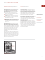 4
4
-
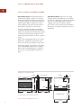 5
5
-
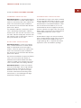 6
6
-
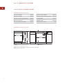 7
7
-
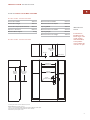 8
8
-
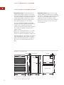 9
9
-
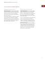 10
10
-
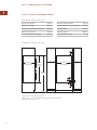 11
11
-
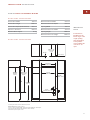 12
12
-
 13
13
-
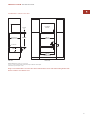 14
14
-
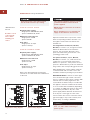 15
15
-
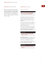 16
16
-
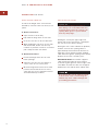 17
17
-
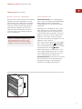 18
18
-
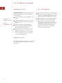 19
19
-
 20
20
-
 21
21
-
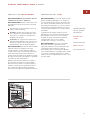 22
22
-
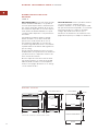 23
23
-
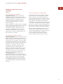 24
24
-
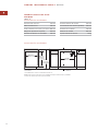 25
25
-
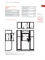 26
26
-
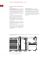 27
27
-
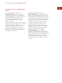 28
28
-
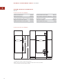 29
29
-
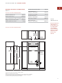 30
30
-
 31
31
-
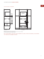 32
32
-
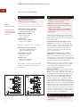 33
33
-
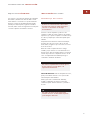 34
34
-
 35
35
-
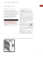 36
36
-
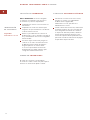 37
37
-
 38
38
-
 39
39
-
 40
40
-
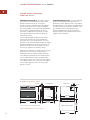 41
41
-
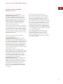 42
42
-
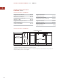 43
43
-
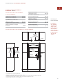 44
44
-
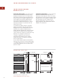 45
45
-
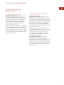 46
46
-
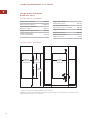 47
47
-
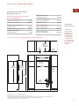 48
48
-
 49
49
-
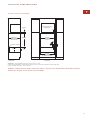 50
50
-
 51
51
-
 52
52
-
 53
53
-
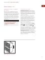 54
54
-
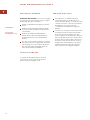 55
55
-
 56
56
-
 57
57
-
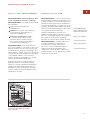 58
58
-
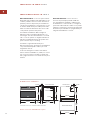 59
59
-
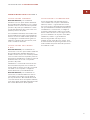 60
60
-
 61
61
-
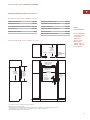 62
62
-
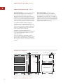 63
63
-
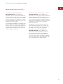 64
64
-
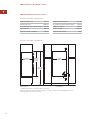 65
65
-
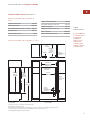 66
66
-
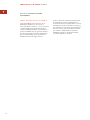 67
67
-
 68
68
-
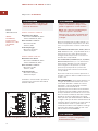 69
69
-
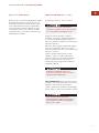 70
70
-
 71
71
-
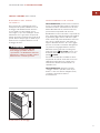 72
72
-
 73
73
-
 74
74
-
 75
75
-
 76
76
-
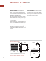 77
77
-
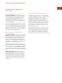 78
78
-
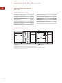 79
79
-
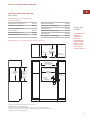 80
80
-
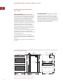 81
81
-
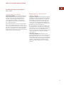 82
82
-
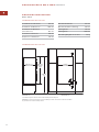 83
83
-
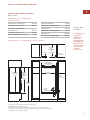 84
84
-
 85
85
-
 86
86
-
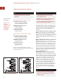 87
87
-
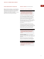 88
88
-
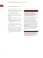 89
89
-
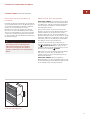 90
90
-
 91
91
-
 92
92
-
 93
93


Wolf E Series Installation Instructions Manual
- Tipo
- Installation Instructions Manual
- Este manual también es adecuado para
en otros idiomas
- français: Wolf E Series
- italiano: Wolf E Series
- English: Wolf E Series
- Deutsch: Wolf E Series
Artículos relacionados
-
Sub-Zero E Series Manual de usuario
-
Wolf E Series Microwave Oven Guía de instalación
-
Wolf E Series Guía de instalación
-
-
-
Wolf Range SO30TE/S/TH El manual del propietario
-
-
-
-