LD Systems CURV 500 TS El manual del propietario
- Categoría
- Juegos de altavoces
- Tipo
- El manual del propietario
Este manual también es adecuado para

USER´S MANUAL
BEDIENUNGSANLEITUNG
MANUEL DUTILISATION
MANUAL DE USUARIO
INSTRUKCJA OBSŁUGI
MANUALE DUSO
操作说明书
操作說明書
CURV 500
®
TS
COMPACT TOURING ARRAY SYSTEM
LDCURV500TS

CONTENTS / INHALTSVERZEICHNIS / CONTENU / CONTENIDO / TREŚĆ / CONTENUTO /
目录 / 目錄
ENGLISH
PREVENTIVE MEASURES 3-4
INTRODUCTION 4
SET-UP 5
CURV 500 TOUR SET SUBWOOFER 6-8
CURV 500 SATELLITES AND SMARTLINK ADAPTER 8-9
CONFIGURATION EXAMPLES 10
OPTIONAL ACCESSORIES 11
TECHNICAL DATA 11-12
MANUFACTURER’S DECLARATIONS 12
DEUTSCH
SICHERHEITSHINWEISE 13-14
EINFÜHRUNG 14
AUFBAU 15
CURV 500 TOUR SET SUBWOOFER 16-18
CURV 500 SATELLITEN UND SMARTLINK ADAPTER 18-19
KONFIGURATIONSBEISPIELE 20
OPTIONALES ZUBEHÖR 21
TECHNISCHE DATEN 21-22
HERSTELLERERKLÄRUNGEN 22
FRANCAIS
MESURES PRÉVENTIVES 23-24
INTRODUCTION 24
STRUCTURE 25
CAISSON DE GRAVES CURV 500 TOUR SET 26-28
ENCEINTES SATELLITES CURV 500 ET ADAPTATEUR
SMARTLINK 28-29
EXEMPLES DE CONFIGURATION 30
ACCESSOIRES DISPONIBLES EN OPTION 31
CARACTÉRISTIQUES TECHNIQUES 31-32
DÉCLARATIONS DU FABRICANT 32
ESPAÑOL
MEDIDAS DE SEGURIDAD 33-34
INTRODUCCIÓN 34
MONTAJE 35
SUBWOOFER CURV 500 TOUR SET 36-38
SATÉLITES CURV 500 Y ADAPTADOR SMARTLINK 38-39
EJEMPLOS DE CONFIGURACIÓN 40
ACCESORIOS OPCIONALES 41
DATOS TÉCNICOS 41-42
DECLARACIONES DEL FABRICANTE 42
POLSKI
ŚRODKI OSTROŻNOŚCI 43-44
WPROWADZENIE 44
MONTAŻ 45
SUBWOOFER CURV 500 TOUR SET 46-48
GŁOŚNIKI SATELITARNE CURV 500 I ADAPTER SMARTLINK 48-49
PRZYKŁADY KONFIGURACJI 50
OPCJONALNE AKCESORIA 51
DANE TECHNICZNE 51-52
OŚWIADCZENIA PRODUCENTA 52
ITALIANO
MISURE PRECAUZIONALI 53-54
INTRODUZIONE 54
INSTALLAZIONE 55
SUBWOOFER CURV 500 TOUR SET 56-58
SATELLITI CURV 500 E ADATTATORE SMARTLINK 58-59
ESEMPI DI CONFIGURAZIONE 60
ACCESSORI OPZIONALI 61
DATI TECNICI 61-62
DICHIARAZIONI DEL PRODUTTORE 62
简体中文
安全注意事項 63-64
簡介 64
安裝 65
CURV500TOURSET巡迴演出套件超低音音箱 66-68
CURV500SATELLITEN衛星音箱和SMARTLINK配接
器 68-69
配置示例 70
選擇性附件 71
技術規格 71
製造商聲明 72
繁體中文
安全须知 73-74
引言 74
安装 75
CURV500TOURSET重低音音箱 76-78
CURV500卫星音箱和SMARTLINK适配器 78-79
配置举例 80
可选配件 81
技术参数 81
制造商声明 82

3
DEUTSCHENGLISH FRANCAIS
ESPAÑOL
POLSKI ITALIANO
简体中文
繁體中文
ENGLISH
YOU‘VE MADE THE RIGHT CHOICE!
We have designed this product to operate reliably over many years. LD Systems stands for this with its name and many years of experience
as a manufacturer of high-quality audio products. Please read this User‘s Manual carefully, so that you can begin making optimum use of
your LD Systems product quickly.
You can find more information about LD SYSTEMS at our Internet site WWW.LD-SYSTEMS.COM
PREVENTIVE MEASURES
1. Please read these instructions carefully.
2. Keep all information and instructions in a safe place.
3. Follow the instructions.
4. Observe all safety warnings. Never remove safety warnings or other information from the equipment.
5. Use the equipment only in the intended manner and for the intended purpose.
6. Use only sufficiently stable and compatible stands and/or mounts (for fixed installations). Make certain that wall mounts are properly installed and
secured. Make certain that the equipment is installed securely and cannot fall down.
7. During installation, observ e the applicable safety regulations for your country.
8. Never install and operate the equipment near radiators, heat registers, ovens or other sources of heat. Make certain that the equipment is always
installed so that is cooled sufficiently and cannot overheat.
9. Never place sources of ignition, e.g., burning candles, on the equipment.
10. Ventilation slits must not be blocked.
11. Keep a minimum distance of 20 cm around and above the device.
12. Do not use this equipment in the immediate vicinity of water (does not apply to special outdoor equipment - in this case, observe the
special instructions noted below. Do not expose this equipment to flammable materials, fluids or gases. Avoid direct sunlight!
13. Make certain that dripping or splashed water cannot enter the equipment. Do not place containers filled with liquids, such as vases or
drinking vessels, on the equipment.
14. Make certain that objects cannot fall into the device.
15. Use this equipment only with the accessories recommended and intended by the manufacturer.
16. Do not open or modify this equipment.
17. After connecting the equipment, check all cables in order to prevent damage or accidents, e.g., due to tripping hazards.
18. During transport, make certain that the equipment cannot fall down and possibly cause property damage and personal injuries.
19. If your equipment is no longer functioning properly, if fluids or objects have gotten inside the equipment or if it has been damaged in anot
her way, switch it off immediately and unplug it from the mains outlet (if it is a powered device). This equipment may only be repaired by
authorized, qualified personnel.
20. Clean the equipment using a dry cloth.
21. Comply with all applicable disposal laws in your country. During disposal of packaging, please separate plastic and paper/cardboard.
22. Plastic bags must be kept out of reach of children.
23. Please note that changes or modifications not expressly approved by the party responsible for compliance could void the user´s authority
to operate the equipment.
FOR EQUIPMENT THAT CONNECTS TO THE POWER MAINS
24. CAUTION: If the power cord of the device is equipped with an earthing contact, then it must be connected to an outlet with a protective
ground. Never deactivate the protective ground of a power cord.
25. If the equipment has been exposed to strong fluctuations in temperature (for example, after transport), do not switch it on immediately.
Moisture and condensation could damage the equipment. Do not switch on the equipment until it has reached room temperature.
26. Before connecting the equipment to the power outlet, first verify that the mains voltage and frequency match the values specified on the
equipment. If the equipment has a voltage selection switch, connect the equipment to the power outlet only if the equipment values and the
mains power values match. If the included power cord or power adapter does not fit in your wall outlet, contact your electrician.
27. Do not step on the power cord. Make certain that the power cable does not become kinked, especially at the mains outlet and/or power
adapter and the equipment connector.
28. When connecting the equipment, make certain that the power cord or power adapter is always freely accessible. Always disconnect the
equipment from the power supply if the equipment is not in use or if you want to clean the equipment. Always unplug the power cord and
power adapter from the power outlet at the plug or adapter and not by pulling on the cord. Never touch the power cord and power adapter
with wet hands.
29. Whenever possible, avoid switching the equipment on and off in quick succession because otherwise this can shorten the useful life of
the equipment.
30. IMPORTANT INFORMATION: Replace fuses only with fuses of the same type and rating. If a fuse blows repeatedly, please contact an
authorised service centre.
31. To disconnect the equipment from the power mains completely, unplug the power cord or power adapter from the power outlet.
32. If your device is equipped with a Volex power connector, the mating Volex equipment connector must be unlocked before it can be removed.
However, this also means that the equipment can slide and fall down if the power cable is pulled, which can lead to personal injuries and/or
other damage. For this reason, always be careful when laying cables.
33. Unplug the power cord and power adapter from the power outlet if there is a risk of a lightning strike or before extended periods of disuse.

4
DEUTSCH
ENGLISH
FRANCAIS
ESPAÑOLPOLSKI
ITALIANO
简体中文繁體中文
CAUTION:
To reduce the risk of electric shock, do not remove cover (or back). There are no user serviceable parts
inside. Maintenance and repairs should be exclusively carried out by qualified service personnel.
The warning triangle with lightning symbol indicates dangerous uninsulated voltage inside the unit, which may cause an
electrical shock.
The warning triangle with exclamation mark indicates important operating and maintenance instructions.
Warning! This symbol indicates a hot surface. Certain parts of the housing can become hot during operation. After use, wait for
a cool-down period of at least 10 minutes before handling or transporting the device.
Warning! This device is designed for use below 2000 metres in altitude.
Warning! This product is not intended for use in tropical climates.
CAUTION! HIGH VOLUMES IN AUDIO PRODUCTS!
This device is meant for professional use. Therefore, commercial use of this equipment is subject to the respectively applicable national
accident prevention rules and regulations. As a manufacturer, Adam Hall is obligated to notify you formally about the existence of potential
health risks.
Hearing damage due to high volume and prolonged exposure: When in use, this product is capable of producing high sound-pressure levels
(SPL) that can lead to irreversible hearing damage in performers, employees, and audience members. For this reason, avoid prolonged
exposure to volumes in excess of 90 dB.
NOTE: This equipment has been tested and found to comply with the limits for a Class B digital device, pursuant to Part 15 of the FCC
Rules. These limits are designed to provide reasonable protection against harmful interference in a residential installation. This equipment
generates, uses and can radiate radio frequency energy and, if not installed and used in accordance with the instructions, may cause
harmful interference to radio communications. However, there is no guarantee that interference will not occur in a particular installation. If
this equipment does cause harmful interference to radio or television reception, which can be determined by turning the equipment off and
on, the user is encouraged to try to correct the interference by one or more of the following measures:
- Reorient or relocate the receiving antenna.
- Increase the separation between the equipment and receiver.
- Connect the equipment into an outlet on a circuit different from that to which the receiver is connected.
- Consult the dealer or an experienced radio/TV technician for help.
INTRODUCTION
General information
Before using, the subwoofer of the LD Systems CURV 500
®
touring array system must be placed on its feet on a flat surface. Never operate
the system on a trolley as there is a risk of the entire system beginning to move uncontrollably. This can result in an accident and/or
damage. In order to ensure sufficient cooling, a space of at least 50 cm must be left between the back of the subwoofer and other surfaces
such as walls. Please take care to connect audio and power cables correctly when using the system and devices such as CD players and
mixing desks which are connected to it. Only use intact cables with a suitable diameter and always unroll cable reels to their full length. If
necessary, use cable protectors to avoid tripping hazards caused by loose cables. Never place the device directly on an edge. Do not place
the subwoofer on a table. To avoid unwanted noises when switching on connected devices, always ensure the system is the last device to
be switched on and the first to be switched off.
The compact, highly portable CURV 500® Touring Array System is fully scalable with up to four interlocking aluminium unibody line array
elements operating on a SmartLink® plug and play adapter. It comes with two standard CURV satellites that feature a single 4“ midrange and
triple 1“ high frequency drivers using LD Systems‘ WaveAhead® technology, and two duplex satellites with twice the speaker complement.
The ported 15“ subwoofer base includes the CURV 500® Touring Array System‘s class D amplification with multiband limiter, short circuit,
thermal and overcurrent protection. It sports comprehensive connectivity on combo and Neutrik speakON connectors, six DSP presets for quick
system configuration, an M20 pole mount and three ergonomic handles for easy portability. Providing impressive versatility, the lightweight
CURV 500® Touring Set delivers high definition audio with powerful punch, superb balance and extended vertical and horizontal coverage. The
set includes a subwoofer pole and dedicated speaker cable.

5
DEUTSCHENGLISH FRANCAIS
ESPAÑOL
POLSKI ITALIANO
简体中文
繁體中文
The LD Systems CURV 500® TS array system is modular in structure so as to allow a range of different configuration options. The LD CURV
500® TS configuration described below is a typical example of a full set-up.
The LD CURV 500® TS Tour Set consists of five components:
A. Subwoofer with integrated DSP (Digital Signal Processor) and Class D amps for the system components.
B. Height-adjustable spacer rod.
C. SmartLink® adapter as a basis for up to two CURV 500® TS double satellites plus two single satellites.
D. Two CURV 500® single satellites with patented click mechanism and WaveAhead® technology.
E. Two CURV 500® double satellites with patented click mechanism and WaveAhead® technology.
Once the subwoofer (A) has been set up in a suitable location, the spacer rod (B) is screwed onto the subwoofer (flange on the top). When
using one double or two single satellites, fit the SmartLink® adapter (C) with the rear flange (labelling: Satellite 1 + 2, upright position, Fig.
F) onto the top of the spacer rod; if using more than one double or two single satellites, fit the adapter to the front flange (labelling: Satellite
3–6, forward tilt position, Fig. G). Now push a single satellite (D) from behind onto the SmartLink® adapter (C) as far as it will go, while
keeping the spring-loaded release button at the side of the satellite pressed down. In doing so, make sure that the two guidance rails of the
satellite are correctly fitted into the grooves on the top of the SmartLink® adapter so as to ensure a solid fit and to establish a connection
between the contacts of the two components. Now release the button back into its original position so as to lock the connection. Proceed in
the same way to expand the system with additional satellites.
Now connect the Neutrik speakON speaker output SAT of the CURV 500® TS subwoofer with the speakON-compatible speaker input INPUT
SIGNAL (H) of the SmartLink® adapter using the speaker cable supplied.
When dismantling the system, proceed in the reverse order. For permanent installation and desktop use, there is a terminal block socket on
the back of the SmartLink® adapter (Fig. I, terminal block connector supplied).
The speaker input INPUT SIGNAL (H) is wired in parallel with the terminal block socket (I).
SET-UP
E
D
C
B
A
G
F
I
C
H

6
DEUTSCH
ENGLISH
FRANCAIS
ESPAÑOLPOLSKI
ITALIANO
简体中文繁體中文
CURV 500 TOUR SET SUBWOOFER
CONNECTIONS, OPERATING AND DISPLAY ELEMENTS
14
2
3
5
4
9
8
1
6
7
13
11 12
10

7
DEUTSCHENGLISH FRANCAIS
ESPAÑOL
POLSKI ITALIANO
简体中文
繁體中文
1
LINE INPUT
Symmetrical line input (XLR).
2
MAIN LEVEL
Control for overall volume. Turn anti-clockwise to reduce overall volume and clockwise to increase overall volume.
3
SUB LEVEL
Set volume of the subwoofer relative to the satellite speakers.
4
POWER LED
The power LED goes on when the device is correctly connected to the mains and switched on.
5
SIGNAL / LIMIT LED
Two-colour display LED. The LED lights up green when the device is receiving an audio signal. The LED lights up red when the speaker
system is being operated in the upper threshold range. Brief illumination of the LED is uncritical here. In order to protect the system, an
excessive signal level is gently down-regulated by the integrated limiter. If the limiter LED lights up for a prolonged period or permanently,
reduce the volume level. Failure to do so can result in distorted sound reproduction and cause damage to the speaker system.
6
THRU
Male 3-pin XLR socket for sending the audio signal received at LINE INPUT.
7
SAT
Neutrik speakON speaker socket for connecting the CURV 500 SmartLink adapter. Alternatively, you can use the speakON socket in the
recessed handle on the top of the subwoofer (suitable speaker cable supplied). If you wish to set up the satellites on the spacer rod and
separate stand (optional), use the two speakON speaker sockets (maximum number of satellites per system is six, one double satellite is
equivalent to two single satellites).
8
NUMBER OF SATELLITES - SET-UP
Button to adapt the DSP settings to the number of satellite speakers being used per SmartLink adapter (here, one double satellite is
equivalent to two single satellites). Press the button until the relevant number of display LEDs light up (see also “CONFIGURATION EXAMPLES”).
9
NUMBER OF SATELLITES - LED 1–6
LEDs for displaying the currently activated DSP presets.
10
POWER IN
Neutrik powerCON mains socket. A suitable power cable is included.
12
POWER ON/OFF
On/off switch for power supply to the device.
12
FUSE
Fuse holder. IMPORTANT: When replacing the fuse, only use a fuse of the same type and value. Follow the instructions printed on the
housing. In the event of repeated fuse failure, please contact an authorised service centre.
13
HOUSING FAN
In order to avoid overheating of the device, ensure that the fan is not obstructed and that air can circulate freely.
14
VENTILATION GRILL
In order to avoid overheating of the device, ensure that the ventilation grill is not covered and that air can circulate freely.

8
DEUTSCH
ENGLISH
FRANCAIS
ESPAÑOLPOLSKI
ITALIANO
简体中文繁體中文
15
SAT OUTPUT
Alternatively, use the speakON socket in the recessed handle on the top of the subwoofer to connect the CURV 500 SmartLink adapter to the
speakON socket on the back of the subwoofer. If you wish to set up the satellites on the spacer rod and separate stand (optional), use the
two speakON speaker sockets (maximum number of satellites per system is six, one double satellite is equivalent to two single satellites).
16
M20 THREAD
M20 thread to attach the speaker spacer rod.
19 19
17
20
18 18
22 22
21 21
19
19
CURV 500 SATELLITES AND SMARTLINK ADAPTER
16
15

9
DEUTSCHENGLISH FRANCAIS
ESPAÑOL
POLSKI ITALIANO
简体中文
繁體中文
17
RELEASE BUTTON
Push a CURV 500 satellite from behind onto the SmartLink® adapter as far as it will go while keeping the spring-loaded release button at
the side of the satellite pressed down. In doing so, make sure that the two guidance rails of the satellite (18) are correctly fitted into the
grooves (19) on the top of the SmartLink® adapter or lower satellite so as to ensure a solid fit and to establish a connection between the
contacts of the two components. Now release the button back into its original position so as to lock the connection. Proceed in the same
way to expand the system with additional satellites.
18
GUIDANCE RAIL – LD CURV 500 (TS) SATELLITE
19
GROOVES – SMARTLINK® ADAPTER OR LD CURVE 500 (TS) SATELLITE
20
M3 THREAD
M3 thread for securing the LD CURV 500 satellite for permanent installation.
21
LOCKING SYSTEM
22
CONTACTS
23
SATELLITE 1/2
Flange for one to two single satellites or one double satellite (upright position).
24
SATELLITE 3–6
Flange for three to six satellites (forward tilt position; here one double satellite is equivalent to two single satellites).
25
INPUT SIGNAL
speakON-compatible speaker input. The speaker input INPUT SIGNAL (25) is wired in parallel with the terminal block socket (26).
26
TERMINAL BLOCK SOCKET
Terminal block socket for permanent installation and desktop use (terminal block connector supplied).
The speaker input INPUT SIGNAL (25) is wired in parallel with the terminal block socket (26).
27
M6 THREAD
M6 thread for attaching the truss mounting adapter LDCURV500TMB.
28
M6 THREAD
M6 thread for attaching the safety eyelet (ring bolt) for truss mounting.
24
25
28
23
28
26
19 19
27 27
26

10
DEUTSCH
ENGLISH
FRANCAIS
ESPAÑOLPOLSKI
ITALIANO
简体中文繁體中文
CONFIGURATION EXAMPLES
LDCURV500TS plus LDCURV500STS (mono)
2 x CURV 500 double satellite
2 x CURV 500 single satellite
1 x CURV 500 double satellite
2 x CURV 500 single satellite
1 x CURV 500 double satellite each
1 x CURV 500 single satellite each

11
DEUTSCHENGLISH FRANCAIS
ESPAÑOL
POLSKI ITALIANO
简体中文
繁體中文
OPTIONAL ACCESSORIES
Padded transport bag for CURV 500 TS satellite Article no.: LDCURV500TSB
Padded protective case for CURV 500 TS subwoofer Article no.: LDCURV500TSSUBPC
Roller board for CURV 500 TS subwoofer Article no.: LDCURV500TSCB
Stand plus SmartLink adapter and 8 m speaker cable Article no.: LDCURV500STS
Truss mounting adapter incl. clamp and ring bolt Article no.: LDCURV500TMB
TECHNICAL DATA
Model number: LDCURV500TS
Product type: PA Complete Systems
System output (RMS):: 1000W
Colour: black
Number of array satellites: 4 (2 single satellites, 2 double satellites)
Number of Smartlink adapters: 1
Number of subwoofers: 1
Max. SPL (continuous): 125dB
Max. SPL (peak): 131dB
Frequency response: 40 - 20000Hz
Dispersion (H x V): 110° horizontal, vertical 34° (1 single satellite = 10° vertical, 1 double satellite = 7° vertical)
RMS: Subwoofer: 700 W , Array Satellites: 300W
Peak power: Subwoofer: 1400 W , Array Satellites: 600W
Amplifier: Class D
Protection circuits: DSP-based multiband limiter, overload, thermal overload, short circuit
Controls: Main Level, Sub Level, Setup, Power On / Off
Indicators: Power, Signal / Limit, Number of satellites
Line inputs: 1
Line input connectors: XLR female
Line outputs: 1 (Thru)
Line output connectors: XLR male
Loudspeaker outputs: 2 (1 x module, 1 x handle on the top, parallel connected, minimum 2.66 ohms in total)
Loudspeaker output connectors: Neutrik speakON
Power supply connection: Neutrik powerCON
Operating voltage: 100V AC - 120V AC / 200V AC - 240V AC, 50 - 60Hz (automatic switching), SMPS
Power consumption (max.): 900W
Ambient temperature (in operation): 0° - 40°C
Relative humidity (in operation): <80% (non condensing)
Weight: 48.2 kg
Accessories (included): Power cord, Speaker cable CURV 500 CABLE 1 (2.2 m), Distance bar
Subwoofer
Low/mid driver dimensions: 15“
Low/mid driver dimensions (mm): 381mm
Cabinet construction: vented
Cabinet material: plywood
Cabinet surface: PA painting
Dimensions Subwoofer (W x H x D): 600 x 437 x 587mm
Subwoofer weight: 35,5kg
Subwoofer features: 4 ergonomic handels, 6 System DSP Presets, powerCON, smart handle with integrated M20
thread and speakON output
Array Satellites (Double)
Mid/Hi system: MF: 2 x 4“ / HF: 6 x 1“ with WaveAhead® Technology / 8 ohms
Array Satellite Features: internal crossover, WaveAhead® Technology, metal grille

12
DEUTSCH
ENGLISH
FRANCAIS
ESPAÑOLPOLSKI
ITALIANO
简体中文繁體中文
MANUFACTURER´S DECLARATIONS
MANUFACTURER‘S WARRANTY & LIMITATIONS OF LIABILITY
You can find our current warranty conditions and limitations of liability at: https://cdn-shop.adamhall.com/media/pdf/MANUFACTU-
RERS-DECLARATIONS_LD_SYSTEMS.pdf .To request warranty service for a product, please contact Adam Hall GmbH, Adam-Hall-Str. 1,
61267 Neu Anspach / Email: [email protected] / +49 (0)6081 / 9419-0.
CORRECT DISPOSAL OF THIS PRODUCT
(valid in the European Union and other European countries with a differentiated waste collection system)
This symbol on the product, or on its documents indicates that the device may not be treated as household waste. This is to avoid
environmental damage or personal injury due to uncontrolled waste disposal. Please dispose of this product separately from other waste
and have it recycled to promote sustainable economic activity. Household users should contact either the retailer where they purchased
this product, or their local government office, for details on where and how they can recycle this item in an environmentally friendly manner.
Business users should contact their supplier and check the terms and conditions of the purchase contract. This product should not be mixed
with other commercial waste for disposal.
FCC STATEMENT
This device complies with Part 15 of the FCC Rules. Operation is subject to the following two conditions:
(1) This device may not cause harmful interference, and
(2) This device must accept any interference received, including interference that may cause undesired operation
CE Compliance
Adam Hall GmbH states that this product meets the following guidelines (where applicable):
R&TTE (1999/5/EC) or RED (2014/53/EU) from June 2017
Low voltage directive (2014/35/EU)
EMV directive (2014/30/EU)
RoHS (2011/65/EU)
The complete declaration of conformity can be found at www.adamhall.com.
Furthermore, you may also direct your enquiry to [email protected].
Array Satellite Material: die-cast aluminium
Array Satellite Surface:: powder coated
Array Satellite Dimensions (W x H x D): 122 x 240 x 126mm
Array Satellite Weight: 3.3kg
Array Satellites
Mid/Hi system: MF: 1 x 4“ / HF: 3 x 1“ with WaveAhead® Technology / 16 ohms
Array Satellite Features: internal crossover, WaveAhead® Technology, metal grille
Array Satellite Material: die-cast aluminium
Array Satellite Surface:: powder coated
Array Satellite Dimensions (W x H x D): 122 x 122 x 122mm
Array Satellite Weight: 1.7kg
Smartlink® Adapter
Smartlink Adapter Features: 2x M6 thread for optional wall mount, 2 x 16 mm pole mount socket
Smartlink Adapter Connectors: 1x Euro-Block connector, 1 x Speakon-compatible
Smartlink Adapter Material: die-cast aluminium
Smartlink Adapter Surface: powder coated
Smartlink Adapter Dimensions (W x H
x D):
122 x 57 x 122mm
Smartlink Adapter Weight: 0.6kg

13
DEUTSCHENGLISH FRANCAIS
ESPAÑOL
POLSKI ITALIANO
简体中文
繁體中文
DEUTSCH
SIE HABEN DIE RICHTIGE WAHL GETROFFEN!
Dieses Gerät wurde unter hohen Qualitätsanforderungen entwickelt und gefertigt, um viele Jahre einen reibungslosen Betrieb zu gewährleisten.
Dafür steht LD Systems mit seinem Namen und der langjährigen Erfahrung als Hersteller hochwertiger Audioprodukte. Bitte lesen Sie diese
Bedienungsanleitung sorgfältig, damit Sie Ihr neues Produkt von LD Systems schnell optimal einsetzen können.
Mehr Informationen zu LD SYSTEMS finden Sie auf unserer Internetseite WWW.LD-SYSTEMS.COM
SICHERHEITSHINWEISE
1. Lesen Sie diese Anleitung bitte sorgfältig durch.
2. Bewahren Sie alle Informationen und Anleitungen an einem sicheren Ort auf.
3. Befolgen Sie die Anweisungen.
4. Beachten Sie alle Warnhinweise. Entfernen Sie keine Sicherheitshinweise oder andere Informationen vom Gerät.
5. Verwenden Sie das Gerät nur in der vorgesehenen Art und Weise.
6. Verwenden Sie ausschließlich stabile und passende Stative bzw. Befestigungen (bei Festinstallationen). Stellen Sie sicher, dass Wandhalterungen
ordnungsgemäß installiert und gesichert sind. Stellen Sie sicher, dass das Gerät sicher installiert ist und nicht herunterfallen kann.
7. Beachten Sie bei der Installation die für Ihr Land geltenden Sicherheitsvorschriften.
8. Installieren und betreiben Sie das Gerät nicht in der Nähe von Heizkörpern, Wärmespeichern, Öfen oder sonstigen Wärmequellen. Sorgen
Sie dafür, dass das Gerät immer so installiert ist, dass es ausreichend gekühlt wird und nicht überhitzen kann.
9. Platzieren Sie keine Zündquellen wie z.B. brennende Kerzen auf dem Gerät.
10. Lüftungsschlitze dürfen nicht blockiert werden.
11. Halten Sie einen Mindestabstand von 20 cm seitlich und oberhalb des Geräts ein.
12. Betreiben Sie das Gerät nicht in unmittelbarer Nähe von Wasser. Bringen Sie das Gerät nicht mit brennbaren Materialien, Flüssigkeiten
oder Gasen in Berührung. Direkte Sonneneinstrahlung vermeiden!
13. Sorgen Sie dafür, dass kein Tropf- oder Spritzwasser in das Gerät eindringen kann. Stellen Sie keine mit Flüssigkeit gefüllten Behältnisse
wie Vasen oder Trinkgefäße auf das Gerät.
14. Sorgen Sie dafür, dass keine Gegenstände in das Gerät fallen können.
15. Betreiben Sie das Gerät nur mit dem vom Hersteller empfohlenen und vorgesehenen Zubehör.
16. Öffnen Sie das Gerät nicht und verändern Sie es nicht.
17. Überprüfen Sie nach dem Anschluss des Geräts alle Kabelwege, um Schäden oder Unfälle, z. B. durch Stolperfallen zu vermeiden.
18. Achten Sie beim Transport darauf, dass das Gerät nicht herunterfallen und dabei möglicherweise Sach- und Personenschäden verursachen kann.
19. Wenn Ihr Gerät nicht mehr ordnungsgemäß funktioniert, Flüssigkeiten oder Gegenstände in das Geräteinnere gelangt sind, oder das
Gerät anderweitig beschädigt wurde, schalten Sie es sofort aus und trennen es von der Netzsteckdose (sofern es sich um ein aktives Gerät
handelt). Dieses Gerät darf nur von autorisiertem Fachpersonal repariert werden.
20. Verwenden Sie zur Reinigung des Geräts ein trockenes Tuch.
21. Beachten Sie alle in Ihrem Land geltenden Entsorgungsgesetze. Trennen Sie bei der Entsorgung der Verpackung bitte Kunststoff und
Papier bzw. Kartonagen voneinander.
22. Kunststoffbeutel müssen außer Reichweite von Kindern aufbewahrt werden.
23. Sämtliche vom Benutzer vorgenommenen Änderungen und Modifikationen, denen die für die Einhaltung der Richtlinien verantwortliche
Partei nicht ausdrücklich zugestimmt hat, können zum Entzug der Betriebserlaubnis für das Gerät führen.
BEI GERÄTEN MIT NETZANSCHLUSS
24. ACHTUNG: Wenn das Netzkabel des Geräts mit einem Schutzkontakt ausgestattet ist, muss es an einer Steckdose mit Schutzleiter
angeschlossen werden. Deaktivieren Sie niemals den Schutzleiter eines Netzkabels.
25. Schalten Sie das Gerät nicht sofort ein, wenn es starken Temperaturschwankungen ausgesetzt war (beispielsweise nach dem Transport).
Feuchtigkeit und Kondensat könnten das Gerät beschädigen. Schalten Sie das Gerät erst ein, wenn es Zimmertemperatur erreicht hat.
26. Bevor Sie das Gerät an die Steckdose anschließen, prüfen Sie zuerst, ob die Spannung und die Frequenz des Stromnetzes mit den auf
dem Gerät angegebenen Werten übereinstimmen. Verfügt das Gerät über einen Spannungswahlschalter, schließen Sie das Gerät nur an die
Steckdose an, wenn die Gerätewerte mit den Werten des Stromnetzes übereinstimmen. Wenn das mitgelieferte Netzkabel bzw. der mitgelie-
ferte Netzadapter nicht in Ihre Netzsteckdose passt, wenden Sie sich an Ihren Elektriker.
27. Treten Sie nicht auf das Netzkabel. Sorgen Sie dafür, dass spannungsführende Kabel speziell an der Netzbuchse bzw. am Netzadapter
und der Gerätebuchse nicht geknickt werden.
28. Achten Sie bei der Verkabelung des Geräts immer darauf, dass das Netzkabel bzw. der Netzadapter stets frei zugänglich ist. Trennen Sie
das Gerät stets von der Stromzuführung, wenn das Gerät nicht benutzt wird, oder Sie das Gerät reinigen möchten. Ziehen Sie Netzkabel und
Netzadapter immer am Stecker bzw. am Adapter und nicht am Kabel aus der Steckdose. Berühren Sie Netzkabel und Netzadapter niemals mit
nassen Händen.
29. Schalten Sie das Gerät möglichst nicht schnell hintereinander ein und aus, da sonst die Lebensdauer des Geräts beeinträchtigt werden könnte.
30. WICHTIGER HINWEIS: Ersetzen Sie Sicherungen ausschließlich durch Sicherungen des gleichen Typs und Wertes. Sollte eine Sicherung
wiederholt auslösen, wenden Sie sich bitte an ein autorisiertes Servicezentrum.
31. Um das Gerät vollständig vom Stromnetz zu trennen, entfernen Sie das Netzkabel bzw. den Netzadapter aus der Steckdose.
32. Wenn Ihr Gerät mit einem verriegelbaren Netzanschluss bestückt ist, muss der passende Gerätestecker entsperrt werden, bevor er entfernt
werden kann. Das bedeutet aber auch, dass das Gerät durch ein Ziehen am Netzkabel verrutschen und herunterfallen kann, wodurch Personen
verletzt werden und/oder andere Schäden auftreten können. Verlegen Sie Ihre Kabel daher immer sorgfältig.
33. Entfernen Sie Netzkabel und Netzadapter aus der Steckdose bei Gefahr eines Blitzschlags oder wenn Sie das Gerät länger nicht verwenden.

14
DEUTSCH
ENGLISH
FRANCAIS
ESPAÑOLPOLSKI
ITALIANO
简体中文繁體中文
ACHTUNG
Entfernen Sie niemals die Abdeckung, da sonst das Risiko eines elektrischen Schlages besteht. Im
Inneren des Geräts befinden sich keine Teile, die vom Bediener repariert oder gewartet werden können.
Lassen Sie Wartung und Reparaturen ausschließlich von qualifiziertem Servicepersonal durchführen.
Das gleichseitige Dreieck mit Blitzsymbol warnt vor nichtisolierten, gefährlichen Spannungen im Geräteinneren, die einen
elektrischen Schlag verursachen können.
Das gleichseitige Dreieck mit Ausrufungszeichen kennzeichnet wichtige Bedienungs- und Wartungshinweise.
Warnung! Dieses Symbol kennzeichnet heiße Oberflächen. Während des Betriebs können bestimmte Teile des Gehäuses heiß
werden. Berühren oder transportieren Sie das Gerät nach einem Einsatz erst nach einer Abkühlzeit von mindestens 10 Minuten.
Warnung! Dieses Gerät ist für eine Nutzung bis zu einer Höhe von maximal 2000 Metern über dem Meeresspiegel bestimmt.
Warnung! Dieses Gerät ist nicht für den Einsatz in tropischen Klimazonen bestimmt.
ACHTUNG HOHE LAUTSTÄRKEN BEI AUDIOPRODUKTEN!
Dieses Gerät ist für den professionellen Einsatz vorgesehen. Der kommerzielle Betrieb dieses Geräts unterliegt den jeweils gültigen
nationalen Vorschriften und Richtlinien zur Unfallverhütung. Als Hersteller ist Adam Hall gesetzlich verpflichtet, Sie ausdrücklich auf mögliche
Gesundheitsrisiken hinzuweisen. Gehörschäden durch hohe Lautstärken und Dauerbelastung: Bei der Verwendung dieses Produkts können
hohe Schalldruckpegel (SPL) erzeugt werden, die bei Künstlern, Mitarbeitern und Zuschauern zu irreparablen Gehörschäden führen können.
Vermeiden Sie länger anhaltende Belastung durch hohe Lautstärken über 90 dB.
EINFÜHRUNG
Allgemeine Hinweise
Der Subwoofer des LD Systems CURV 500
®
touring array system muss vor der Inbetriebnahme auf ebener Fläche auf seine Füße gestellt
werden. Betreiben Sie das System niemals auf einem Rollwagen, da die Gefahr besteht, dass sich das gesamte System unkontrolliert in
Bewegung setzt. Unfälle und Beschädigungen können die Folge sein. Um eine ausreichende Kühlung zu gewährleisten, muss bei Betrieb
zwischen der Rückseite des Subwoofers und anderen Objekten wie Wänden o. ä. ein Mindestabstand von 50 cm eingehalten werden.
Bitte achten Sie bei dem System sowie den angeschlossenen Geräten wie Mischpulten, CD-Playern etc. auf den korrekten Anschluss von
Audio- und Stromverbindungen. Verwenden Sie ausschließlich unbeschädigte Kabel mit geeignetem Durchmesser und rollen Sie Kabelrollen
immer vollständig ab. Verwenden Sie gegebenenfalls Kabelbrücken, um Stolperfallen durch lose Kabel zu vermeiden. Stellen Sie das Gerät
niemals direkt an einer Kante auf. Positionieren Sie den Subwoofer nicht auf einem Tisch. Um ungewollte Nebengeräusche beim Einschalten
angeschlossener Geräte zu vermeiden, schalten Sie das System immer als letztes Gerät ein und als erstes Gerät aus.
Das kompakte CURV 500
®
Touring Array System ist besonders transportfreundlich und umfassend skalierbar – mit bis zu vier miteinander
verriegelten Line-Array-Elementen aus Aluminium im Unibody-Design, die sich nach dem Plug-and-Play-Prinzip schnell und einfach mit
dem zugehörigen SmartLink
®
-Adapter kombinieren lassen. Der Lieferumfang beinhaltet zwei Standard-CURV-Satelliten mit je einem
4”-Mitteltöner und drei 1”-Hochtönern mit LD Systems WaveAhead®-Technologie sowie zwei Duplex-Satelliten mit doppelter Lautsprecher-
bestückung.
Als Basis des CURV 500
®
Touring Array Systems dient der 15”-Bassreflex-Subwoofer mit integriertem Class D-Verstärker plus Multi-
band-Limiter und Schutzschaltungen gegen Kurzschluss, Überhitzung und Überstrom. Der Subwoofer bietet vielfältige Anschlussmöglich-
keiten mit Combo- und Neutrik speakON Steckverbindern, sechs DSP-Presets zur schnellen Systemkonfiguration, einen M20-Hochstän-
derflansch und drei ergonomische Tragegriffe. Mit seinem niedrigen Gewicht ist das CURV 500
®
Touring Set eine beeindruckend flexible
PA-Lösung, die sich durch eine hochauflösende Audiowiedergabe mit druckvollem, sehr ausgewogenem Klang und weitem vertikalen und
horizontalen Abstrahlwinkel auszeichnet. Zum Set gehören außerdem eine Distanzstange und ein separates Lautsprecherkabel.

15
DEUTSCHENGLISH FRANCAIS
ESPAÑOL
POLSKI ITALIANO
简体中文
繁體中文
E
D
C
B
A
Um eine Vielzahl verschiedener Konfigurationsmöglichkeiten zu ermöglichen, ist das LD Systems CURV 500® TS Array-System modular
aufgebaut. Repräsentativ steht nachfolgend beschrieben die Konfiguration des LD CURV 500® TS als Vollausbau.
Das LD CURV 500® TS Tour Set besteht aus 5 Komponenten:
A. Subwoofer mit integriertem DSP (Digitaler Signalprozessor) und Class-D Endstufen für die Systemkomponenten.
B. Höhenverstellbare Distanzstange.
C. SmartLink® Adapter als Basis für bis zu 2 CURV 500® TS Doppel-Satelliten plus 2 Einzel-Satelliten.
D. Zwei CURV 500® Einzel-Satelliten mit patentiertem Klick-Mechanismus und WaveAhead® Technologie.
E. Zwei CURV 500® TS Doppel-Satelliten mit patentiertem Klick-Mechanismus und WaveAhead® Technologie.
Nachdem der Subwoofer (A) an einer geeigneten Stelle aufgestellt wurde, wird die Distanzstange (B) auf den Subwoofer aufgeschraubt (Flansch
auf der Oberseite). Bei der Verwendung von 1 Doppel- oder 2 Einzel-Satelliten stecken Sie nun den SmartLink® Adapter (C) mit dem hinteren
Flansch (Markierung Satellite 1 + 2, aufrechte Position, Abb. F) oben auf die Distanzstange, bei der Verwendung von mehr als 1 Doppel-
oder 2 Einzel-Satelliten mit dem vorderen Flansch (Markierung Satellite 3 - 6, nach vorn geneigte Position, Abb. G). Schieben Sie nun einen
Einzel-Satelliten (D) von hinten auf den SmartLink® Adapter (C) bis zum Anschlag, während Sie den gefederten Entriegelungsknopf an der
Seite des Satelliten drücken. Achten Sie dabei darauf, dass die beiden Führungsschienen des Satelliten korrekt in die Nuten auf der Oberseite
des SmartLink® Adapters eingeführt werden, um einen festen Sitz zu gewährleisten und die Verbindung der Kontakte beider Komponenten
herzustellen. Lösen Sie nun den Druck auf den Entriegelungsknopf, um ihn wieder in die Ursprungsposition zu bringen und die Verbindung zu
verriegeln. Gehen Sie in der gleichen, zuvor beschriebenen Weise vor, um das System um weitere Satelliten zu erweitern.
Verbinden Sie nun den Neutrik speakON Lautsprecher-Ausgang SAT des CURV 500® TS Subwoofers mit dem Speakon-kompatiblen Laut-
sprecher-Eingang INPUT SIGNAL (H) des SmartLink® Adapters mit Hilfe des mitgelieferten Lautsprecherkabels.
Beim Abbau gehen Sie bitte in umgekehrter Reihenfolge vor. Für die feste Installation und Desktop-Anwendung befindet sich auf der
Rückseite des SmartLink® Adapters ein Schraub-Steck-Anschluß (Abb. I, Schraub-Steck-Verbinder im Lieferumfang).
Der Lautsprecher-Eingang INPUT SIGNAL (H) ist mit dem Schraub-Steck-Anschluß (I) parallel verkabelt.
AUFBAU
G
F
I
C
H

16
DEUTSCH
ENGLISH
FRANCAIS
ESPAÑOLPOLSKI
ITALIANO
简体中文繁體中文
CURV 500 TOUR SET SUBWOOFER
ANSCHLÜSSE, BEDIEN- UND ANZEIGEELEMENTE
14
2
3
5
4
9
8
1
6
7
13
11 12
10

17
DEUTSCHENGLISH FRANCAIS
ESPAÑOL
POLSKI ITALIANO
简体中文
繁體中文
1
LINE INPUT
Symmetrischer Line-Eingang (XLR).
2
MAIN LEVEL
Regler für die Gesamtlautstärke. Nach links gedreht wird die Gesamtlautstärke abgesenkt, nach rechts gedreht angehoben.
3
SUB LEVEL
Einstellung des Lautstärkeverhältnisses des Subwoofers zu den Satelliten-Lautsprechern.
4
POWER LED
Die Power LED leuchtet, wenn das Gerät korrekt am Stromnetz angeschlossen und eingeschaltet ist.
5
SIGNAL / LIMIT LED
Zweifarbige Anzeige-LED. Die LED leuchtet grün auf, wenn am Gerät ein Audiosignal anliegt. Die LED leuchtet rot auf, wenn das
Lautsprecher-System im oberen Grenzbereich betrieben wird. Ein kurzes Aufleuchten der LED ist dabei unkritisch. Um das System zu schützen,
wird ein überhöhter Signal-Pegel vom integrierten Limiter sanft heruntergeregelt. Leuchtet die Limiter-LED länger oder dauerhaft, reduzieren Sie
den Lautstärkepegel. Eine Nichtbeachtung kann zu einer verzerrten Klangwiedergabe und zur Beschädigung des Lautsprechersystems führen.
6
THRU
Männliche 3-Pol XLR-Buchse zum Weiterleiten des am LINE INPUT anliegenden Audio-Signals.
7
SAT
Neutrik speakON Lautsprecherbuchse zum Anschließen des CURV 500 SmartLink-Adapters. Nutzen Sie alternativ die speakON Buchse
in der Griffmulde auf der Oberseite des Subwoofers (geeignetes Lautsprecherkabel im Lieferumfang). Für den Aufbau der Satelliten auf
Distanzstange und separatem Stativ (optional) verwenden Sie bitte beide speakON Lautsprecherbuchsen (maximale Anzahl Satelliten pro
System ist 6, 1 Doppel-Satellit entspricht hierbei 2 Einzel-Satelliten).
8
NUMBER OF SATELLITES - SETUP
Taster zum Anpassen der DSP-Einstellungen an die Anzahl der pro SmartLink Adapter verwendeten Satelliten-Lautsprecher
(1 Doppel-Satellit entspricht hierbei 2 Einzel-Satelliten). Drücken Sie den Taster so oft, bis die entsprechende Anzahl der Anzeige-LEDs
leuchtet (siehe auch „KONFIGURATIONSBEISPIELE“).
9
NUMBER OF SATELLITES - LED 1 - 6
LEDs zum Anzeigen des aktuell aktivierten DSP-Presets.
10
POWER IN
Neutrik powerCON Netzbuchse. Ein geeignetes Netzkabel befindet sich im Lieferumfang.
12
POWER ON / OFF
Ein- / Ausschalter für die Spannungszufuhr des Geräts.
12
FUSE
Sicherungshalter. WICHTIGER HINWEIS: Ersetzen Sie die Sicherung ausschließlich durch eine Sicherung des gleichen Typs und mit gleichen
Werten. Achten Sie auf den Aufdruck auf dem Gehäuse. Sollte die Sicherung wiederholt auslösen, wenden Sie sich bitte an ein autorisiertes
Servicezentrum.
13
GEHÄUSELÜFTER
Um Überhitzung des Geräts zu vermeiden, achten Sie darauf, dass der Lüfter nicht abgedeckt wird und Luft ungehindert zirkulieren kann.
14
LÜFTUNGSGITTER
Um Überhitzung des Geräts zu vermeiden, achten Sie darauf, dass das Lüftungsgitter nicht abgedeckt wird und Luft ungehindert zirkulieren kann.

18
DEUTSCH
ENGLISH
FRANCAIS
ESPAÑOLPOLSKI
ITALIANO
简体中文繁體中文
15
SAT OUTPUT
Nutzen Sie die speakON Buchse in der Griffmulde auf der Oberseite des Subwoofers zum Anschließen des CURV 500 SmartLink-Adapters
alternativ zu der speakON Buchse auf der Subwoofer-Rückseite. Für den Aufbau der Satelliten auf Distanzstange und separatem Stativ (optional)
verwenden Sie bitte beide speakON Lautsprecherbuchsen (maximale Anzahl Satelliten pro System ist 6, 1 Doppel-Satellit entspricht hierbei 2
Einzel-Satelliten).
16
M20 GEWINDE
M20 Gewinde zum Anbringen der Lautsprecher-Distanzstange.
16
15
CURV 500 SATELLITEN UND SMARTLINK ADAPTER
22 22
21 21
19
19
19 19
17
20
18 18

19
DEUTSCHENGLISH FRANCAIS
ESPAÑOL
POLSKI ITALIANO
简体中文
繁體中文
17
ENTRIEGELUNGSKNOPF
Schieben Sie einen CURV 500 Satelliten von hinten auf den SmartLink® Adapter bis zum Anschlag, während Sie den gefederten Entrie-
gelungsknopf an der Seite des Satelliten drücken. Achten Sie dabei darauf, dass die beiden Führungsschienen des Satelliten (18) korrekt
in die Nuten (19) auf der Oberseite des SmartLink® Adapters, bzw. des unteren Satelliten eingeführt werden, um einen festen Sitz zu
gewährleisten und die Verbindung der Kontakte beider Komponenten herzustellen. Lösen Sie nun den Druck auf den Entriegelungsknopf um
ihn wieder in die Ursprungsposition zu bringen und die Verbindung zu verriegeln. Gehen Sie in der gleichen, zuvor beschriebenen Weise vor,
um das System um weitere Satelliten zu erweitern.
18
FÜHRUNGSSCHIENE LD CURV 500(TS) SATELLIT
19
NUTEN SMARTLINK® ADAPTER BZW. LD CURVE 500 (TS) SATELLIT
20
M3 GEWINDE
M3 Gewinde zum Sichern der LD CURV 500 Satelliten bei der Festinstallation.
21
VERRIEGELUNGSSYSTEM
22
KONTAKTE
23
SATELLITE 1 / 2
Flansch für 1 bis 2 Einzel-Satelliten bzw. 1 Doppel-Satellit (aufrechte Position).
24
SATELLITE 3 - 6
Flansch für 3 bis 6 Satelliten (nach vorn geneigte Position, 1 Doppel-Satellit entspricht hierbei 2 Einzel-Satelliten).
25
INPUT SIGNAL
Speakon-kompatibler Lautsprecher-Eingang. Der Lautsprecher-Eingang INPUT SIGNAL (25) ist mit dem Schraub-Steck-Anschluß (26)
parallel verkabelt.
26
SCHRAUB-STECK-ANSCHLUSS
Schraub-Steck-Anschluss für die Festinstallation und Desktop-Anwendung (Schraub-Steck-Verbinder im Lieferumfang).
Der Lautsprecher-Eingang INPUT SIGNAL (25) ist mit dem Schraub-Steck-Anschluß (26) parallel verkabelt.
27
M6 GEWINDE
M6 Gewinde zum Anbringen des Trussmontageadapters LDCURV500TMB.
28
M6 GEWINDE
M6 Gewinde zum Anbringen der Sicherungsöse (Ringschraube) bei der Trussmontage.
24
25
28
23
28
26
19 19
27 27
26

20
DEUTSCH
ENGLISH
FRANCAIS
ESPAÑOLPOLSKI
ITALIANO
简体中文繁體中文
KONFIGURATIONSBEISPIELE
LDCURV500TS plus LDCURV500STS (Mono)
2 x CURV 500 Doppel-Satellit
2 x CURV 500 Einzel-Satellit
1 x CURV 500 Doppel-Satellit
2 x CURV 500 Einzel-Satellit
Je 1 x CURV 500 Doppel-Satellit
Je 1 x CURV 500 Einzel-Satellit

21
DEUTSCHENGLISH FRANCAIS
ESPAÑOL
POLSKI ITALIANO
简体中文
繁體中文
OPTIONALES ZUBEHÖR
Gepolsterte Transporttasche für CURV 500 TS Satelliten Artikelnr.: LDCURV500TSB
Gepolsterte Schutzhülle für CURV 500 TS Subwoofer Artikelnr.: LDCURV500TSSUBPC
Rollbrett für CURV 500 TS Subwoofer Artikelnr.: LDCURV500TSCB
Stativ plus SmartLink Adapter und 8 m Lautsprecherkabel Artikelnr.: LDCURV500STS
Trussmontageadapter inkl. Klemme und Ringschraube Artikelnr.: LDCURV500TMB
TECHNISCHE DATEN
Modellbezeichnung: LDCURV500TS
Produkttyp: PA-Komplettsystem
System-Ausgangsleistung (RMS): 1.000 W
Farbe: schwarz
Anzahl der Array-Satelliten: 4 (2 Einzel-Satelliten, 2 Doppel-Satelliten)
Anzahl der Smartlink-Adapter: 1
Anzahl der Subwoofer: 1
Max. Schalldruckpegel (kontinuierlich): 125 dB
Max. Schalldruckpegel (Peak): 131 dB
Frequenzgang: 40 – 20.000 Hz
Abstrahlwinkel (H x V): 110° horizontal, 34° vertikal (1 Einzel-Satellit = 10° vertikal, 1 Doppel-Satellit = 7° vertikal)
Leistung (RMS): Subwoofer: 700 W, Array-Satelliten: 300 W
Leistung (Peak): Subwoofer: 1400 W, Array-Satelliten: 600 W
Verstärker: Klasse D
Schutzschaltungen: DSP-basierter Multiband-Limiter, Überlastung, Überhitzung, Kurzschluss
Bedienelemente: Ausgangspegel (Main), Subwoofer-Pegel, Setup, Netzschalter (Power On/Off)
Anzeigen: Netz (Power), Signal/Limiter, Anzahl der Satelliten
Line-Eingänge: 1
Anschlüsse Line-Eingänge: XLR(f)
Line-Ausgänge: 1 (Thru)
Anschlüsse Line-Ausgänge: XLR(m)
Lautsprecherausgänge: 2 (1 x Modul, 1 x Tragegriff oben, parallel verschaltet, insgesamt mindestens 2,66 Ohm)
Anschlüsse Lautsprecherausgänge: Neutrik speakON
Stromversorgungsanschluss: Neutrik powerCON
Betriebsspannung: 100 V AC – 120 V AC / 200 V AC – 240 V AC, 50 – 60 Hz (automatische Anpassung), Schalt-
netzteil
Leistungsaufnahme (max.): 900 W
Umgebungstemperatur (in Betrieb): 0°C ... 40°C
Relative Luftfeuchte (in Betrieb): <80% (nicht kondensierend)
Gewicht: 48.2 kg
Zubehör (im Lieferumfang): Netzkabel, Lautsprecherkabel CURV 500 CABLE 1 (2,2 m), Distanzstange
Subwoofer
Größe Tief-/Mitteltöner: 15"
Größe Tief-/Mitteltöner (mm): 381 mm
Gehäusekonstruktion: Bassreflex
Gehäusematerial: Sperrholz
Gehäuseoberfläche: PA-Lack
Abmessungen Subwoofer (B x H x T): 600 x 437 x 587 mm
Gewicht Subwoofer: 35,5 kg
Subwoofer – Eigenschaften: 4 ergonomische Griffe, 6 System-DSP-Presets, powerCON, Smart-Handle (Tragegriff) mit
integriertem M20-Gewindeflansch und speakON-Ausgang

22
DEUTSCH
ENGLISH
FRANCAIS
ESPAÑOLPOLSKI
ITALIANO
简体中文繁體中文
HERSTELLERERKLÄRUNGEN
HERSTELLERGARANTIE & HAFTUNGSBESCHRÄNKUNG
Unsere aktuellen Garantiebedingungen und Haftungsbeschränkung finden Sie unter: https://cdn-shop.adamhall.com/media/pdf/MANUFAC-
TURERS-DECLARATIONS_LD_SYSTEMS.pdf. Im Service Fall wenden Sie sich bitte an Adam Hall GmbH, Adam-Hall-Str. 1,
61267 Neu Anspach / E-Mail [email protected] / +49 (0)6081 / 9419-0.
KORREKTE ENTSORGUNG DIESES PRODUKTS
(Gültig in der Europäischen Union und anderen europäischen Ländern mit Mülltrennung) Dieses Symbol auf dem Produkt oder dazu-
gehörigen Dokumenten weist darauf hin, dass das Gerät am Ende der Produktlebenszeit nicht zusammen mit dem normalen Hausmüll
entsorgt werden darf, um Umwelt- oder Personenschäden durch unkontrollierte Abfallentsorgung zu vermeiden. Bitte entsorgen Sie dieses
Produkt getrennt von anderen Abfällen und führen es zur Förderung nachhaltiger Wirtschaftskreisläufe dem Recycling zu. Als Privatkunde
erhalten Sie Informationen zu umweltfreundlichen Entsorgungsmöglichkeiten über den Händler, bei dem das Produkt erwor¬ben wurde, oder
über die entsprechenden regionalen Behörden. Als gewerblicher Nutzer kontaktieren Sie bitte Ihren Lieferanten und prüfen die ggf. vertraglich
vereinbarten Konditionen zur Entsorgung der Geräte. Dieses Produkt darf nicht zusammen mit anderen gewerblichen Abfällen entsorgt werden.
CE-Konformität
Hiermit erklärt die Adam Hall GmbH, dass dieses Produkt folgenden Richtlinien entspricht (soweit zutreffend):
R&TTE (1999/5/EG) bzw. RED (2014/53/EU) ab Juni 2017
Niederspannungsrichtlinie (2014/35/EU)
EMV-Richtlinie (2014/30/EU)
RoHS (2011/65/EU)
Die vollständige Konformitätserklärung finden Sie unter www.adamhall.com.
Des Weiteren können Sie diese auch unter [email protected] anfragen.
Array-Satelliten (doppelt)
Mittel-/Hochtöner-System: Mitteltöner: 2 x 4" / Hochtöner: 6 x 1" mit WaveAhead®-Technologie / 8 Ohm
Array-Satelliten – Eigenschaften: interne Frequenzweiche, WaveAhead®-Technologie, Metall-Schutzgitter
Array-Satelliten – Material: Aluminium-Druckguss
Array-Satelliten – Oberfläche: pulverbeschichtet
Array-Satelliten – Abmessungen (B x
H x T):
122 x 240 x 126 mm
Array-Satelliten – Gewicht: 3,3 kg
Array-Satelliten
Mittel-/Hochtöner-System: Mitteltöner: 1 x 4" / Hochtöner: 3 x 1" mit WaveAhead®-Technologie / 16 Ohm
Array-Satelliten – Eigenschaften: interne Frequenzweiche, WaveAhead®-Technologie, Metall-Schutzgitter
Array-Satelliten – Material: Aluminium-Druckguss
Array-Satelliten – Oberfläche: pulverbeschichtet
Array-Satelliten – Abmessungen (B x
H x T):
122 x 122 x 122 mm
Array-Satelliten – Gewicht: 1,7 kg
Smartlink®-Adapter
Smartlink-Adapter – Eigenschaften: 2 x M6-Gewinde für optionale Wandhalterung, 2 x 16 mm Stativflansch
Smartlink-Adapter – Anschlüsse: 1 x Euro-Block (Klemmleiste), 1 x speakON-kompatibel
Smartlink-Adapter – Material: Aluminium-Druckguss
Smartlink-Adapter – Oberfläche: pulverbeschichtet
Smartlink-Adapter – Abmessungen
(B x H x T):
122 x 57 x 122 mm
Smartlink-Adapter – Gewicht: 0,6 kg

23
DEUTSCHENGLISH FRANCAIS
ESPAÑOL
POLSKI ITALIANO
简体中文
繁體中文
FRANCAIS
VOUS AVEZ FAIT LE BON CHOIX!
Cet appareil a été développé et fabriqué en appliquant des exigences de qualité très élevées : il garantit des années de fonctionnement sans
problème. Grâce à de nombreuses années d‘expérience, LD Systems est un nom connu dans le domaine des produits audio haut de gamme.
Veuillez lire attentivement ce Manuel Utilisateur : vous apprendrez rapidement à utiliser votre appareil LD Systems de façon optimale.
Pour plus d‘informations sur LD Systems, visitez notre site Web, WWW.LD-SYSTEMS.COM
MESURES PRÉVENTIVES
1. Veuillez lire attentivement ce manuel.
2. Rangez tous les documents d‘information et d‘instructions en lieu sûr.
3. Veuillez suivre toutes les instructions
4. Observez tous les messages d‘avertissement N‘enlevez pas de l‘appareil les étiquettes de sécurité ou autres informations.
5. N‘utilisez l‘appareil que pour des applications et de la façon appropriées.
6. Utilisez exclusivement des pieds et des dispositifs de fixation stables et adaptés lorsque l‘appareil est utilisé en installation fixe.
Assurez-vous que les fixations murales ont été montées correctement, et qu‘elles sont sécurisées. Vérifiez que l‘appareil est installé en toute
sécurité, et qu‘il ne peut pas tomber.
7. Lors de l‘installation, observez les règlementations de sécurité en vigueur dans votre pays.
8. N‘installez et n‘utilisez pas l‘appareil à proximité de radiateurs, d‘accumulateurs de chaleur, de fours ou de toute autre source de chaleur. Vérifiez
que l‘appareil est installé de façon à bénéficier en permanence d‘un refroidissement efficace et qu‘il ne peut pas chauffer de façon excessive.
9. Ne placez aucune source de flamme sur l‘appareil – par exemple, une bougie allumée.
10. Ne bloquez pas les ouïes d‘aération. Éviter toute exposition directe aux rayons du soleil !
11. Gardez une distance minimale de 20 cm autour et au-dessus de l‘appareil.
12. N‘utilisez pas l‘appareil à proximité immédiate d‘eau (à moins qu‘il ne s‘agisse d‘un appareil conçu pour une utilisation en extérieur –
dans ce cas, respectez les instructions correspondantes ci après) Ne mettez pas l‘appareil en contact avec des matériaux, des liquides ou
des gaz inflammables.
13. Vérifiez qu‘aucune projection ou liquide ne puisse s‘introduire dans l‘appareil. Ne posez sur l‘appareil aucun objet renfermant du liquide
: vase, verre d‘eau...
14. Vérifiez qu‘aucun petit objet ne puisse tomber à l‘intérieur de l‘appareil.
15. N‘utilisez avec cet appareil que des accessoires recommandés et approuvés par le fabricant.
16. N‘ouvrez pas l‘appareil, et n‘essayez pas de le modifier.
17. Lors du branchement de l‘appareil, sécurisez le passage du câble secteur, afin d‘éviter tout dommage ou accident, par exemple quel-
qu‘un qui trébuche sur le câble.
18. Lors du transport, vérifiez que l‘appareil ne peut tomber, ce qui pourrait provoquer des dommages matériels et/ou corporels.
19. Si votre appareil ne fonctionne plus correctement, que de l‘eau ou des objets ont pénétré à l‘intérieur, ou qu‘il a été endommagé de
quelque façon que ce soit, éteignez-le immédiatement et débranchez sa prise secteur (s‘il s‘agit d‘un appareil alimenté). Cet appareil ne
doit être réparé que par un personnel autorisé.
20. Pour le nettoyage de l‘appareil, utilisez un chiffon sec/
21. Observez toutes les réglementations en vigueur dans votre pays pour mettre l‘appareil au rebut. Lorsque vous jetez l‘emballage de
l‘appareil, veuillez séparer plastique, papier et carton.
22. Les films plastique doivent être mis hors de portée des enfants.
23. Veuillez noter que les changements ou modifications n‘ayant pas été expressément approuvés par la partie responsable de la conformité
pourraient annuler le droit accordé à l‘utilisateur de faire fonctionner l‘équipement.
APPAREILS RELIÉS AU SECTEUR
24. ATTENTION : Si le câble de l‘appareil est muni d‘un fil de terre, il doit être relié à une prise murale avec terre. Ne désactivez jamais la
mise à la terre d‘un appareil.
25. N‘allumez pas l‘appareil immédiatement s‘il a subi une grande différence de température ambiante (par exemple, lors du transport). L‘humidité
et la condensation pourraient l‘endommager. Ne mettez l‘appareil sous tension que lorsqu‘il est parvenu à la température de la pièce.
26. Avant de relier l‘appareil à la prise murale, vérifiez que la valeur et la fréquence de tension secteur sur laquelle il est réglé correspon-
dent bien à la valeur et à la fréquence de la tension secteur locale. Si l‘appareil possède un sélecteur de tension, ne le branchez sur la prise
murale qu‘après avoir vérifié que la valeur réglée correspond à la valeur effective de la tension secteur. Si la fiche du cordon secteur ou du
bloc adaptateur livré avec votre appareil ne correspond pas au format de votre prise murale, veuillez consulter un électricien.
27. Ne piétinez pas le câble secteur. Assurez-vous que le câble secteur n‘est pas trop pincé, notamment au niveau de l‘arrière de l‘appareil
(ou de son adaptateur secteur) et de la prise murale.
28. Lors du branchement de l‘appareil, vérifiez que l‘accès au câble secteur ou au bloc adaptateur reste facile. Sortez la fiche secteur de la
prise murale dès que vous n‘utilisez pas l‘appareil pendant un certain temps, ou si vous désirez nettoyer l‘appareil. Pour ce faire, tirez toujours
sur la fiche elle-même, ou sur le bloc secteur lui-même ; ne tirez jamais sur le câble. Ne manipulez jamais le câble secteur ou l‘adaptateur
secteur avec des mains mouillées.
29. N‘éteignez/rallumez pas l‘appareil rapidement plusieurs fois de suite : vosu risquez de réduire la longévité de ses composants internes.
30. CONSEIL IMPORTANT : Ne remplacez le fusible que par un fusible de même type et du même calibre. Si le fusible fond de façon répétée,
veuillez consulter un centre de réparations agréé.
31. Pour séparer complètement l‘appareil du secteur, débranchez le cordon secteur ou l‘adaptateur de la prise murale.
32. Si votre appareil est muni d‘un connecteur secteur verrouillable (Volex), il faut d‘abord déverrouiller le mécanisme avant d‘enlever le
cordon secteur. Attention, lorsque vous retirez le câble secteur, à ne pas faire bouger l‘appareil, ce qui pourrait se traduire par un risque de
chute, de blesser quelqu‘un, ou tout autre dommage. Manipulez toujours le cordon secteur avec soin.

24
DEUTSCH
ENGLISH
FRANCAIS
ESPAÑOLPOLSKI
ITALIANO
简体中文繁體中文
33. Débranchez la fiche secteur ou l‘adaptateur de la prise murale en cas d‘orage, ou si vous n‘utilisez pas l‘appareil pendant une longue période.
ATTENTION :
Ne démontez jamais le couvercle de l‘appareil, vous risquez de recevoir un choc électrique.
L‘appareil ne renferme aucune pièce ni composant réparable ou remplaçable par l‘utilisateur. Ne
confiez l‘entretien et la réparation qu‘à un personnel qualifié.
Le pictogramme en forme de triangle équilatéral contenant un éclair terminé d‘une flèche avertit l‘utilisateur de la présence
d‘une tension dangereuse à l‘intérieur de l‘appareil, tension susceptible de provoquer un choc électrique.
Le pictogramme en forme de triangle équilatéral renfermant un point d‘exclamation signale à l‘utilisateur la présence
d‘instructions importantes concernant l‘utilisation ou l‘entretien de l‘appareil.
ATTENTION ! Ce symbole correspond à des surfaces chaudes. En cours de fonctionnement, certaines parties de l’appareil peuvent
devenir chaudes. Après utilisation, ne manipulez ou ne transportez l’appareil qu’au bout de 10 minutes de refroidissement.
Attention ! Cet appareil est conçu pour une utilisation à une altitude maximale de 2000 m au-dessus du niveau de la mer.
Attention ! Ce produit ne convient pas à une utilisation dans les climats tropicaux.
ATTENTION ! NIVEAUX SONORES ÉLEVÉS SUR LES PRODUITS AUDIO
Cet appareil a été conçu en vue d‘une utilisation professionnelle. L‘utilisation commerciale de cet appareil est soumise aux réglementations
et directives en vigueur dans votre pays en matière de prévention d‘accident. En tant que fabricant, Adam Hall est tenu de vous avertir
formellement des risques relatifs à la santé. Risques provoqués par une exposition prolongée à des niveaux sonores élevés : Lors de
l‘utilisation de ce produit, il est possible d‘atteindre des niveaux de pression sonore (exprimés en dB SPL) élevés, susceptibles de provoquer
des dommages auditifs irréparables chez les artistes, les techniciens et le public. Évitez toute exposition prolongée à des niveaux de
pression sonore élevés (supérieurs à 90 dB SPL).
INTRODUCTION
Remarques générales
Le caisson de graves du système line CURV 500® Touring Array Systems conçu par LD Systems doit être placé sur ses pieds et sur une
surface plane avant sa mise en service. N'utilisez jamais le système s'il est posé sur un chariot à roulettes car le système risque de se
mettre à bouger de façon incontrôlée, ce qui peut provoquer des accidents et des dommages. Afin de garantir un refroidissement suffisant
lors de l'utilisation, il convient de respecter une distance minimale de 50cm entre la paroi arrière du caisson de graves et d'autres
éléments, comme un mur par exemple. Veuillez vous assurer que les raccords électriques et audio sont bien raccordés au système ainsi
qu'aux autres appareils connectés comme les consoles de mixage, les lecteurs CD etc. Utilisez uniquement des câbles en parfait état ayant
le diamètre adéquat, et déroulez toujours entièrement le rouleau de câble. Si nécessaire, utilisez des passages de câble afin d'éviter tout
risque de chute ou de trébuchement lié à des câbles en vrac sur le sol. Ne posez jamais l'appareil directement sur une arête. N'installez pas
le caisson de graves sur une table. Pour éviter tout crépitement lors de la mise sous tension des appareils raccordés, allumez toujours le
système en dernier, et éteignez le en premier.
Le système Touring Array CURV 500®, compact et facilement transportable, est entièrement évolutif : il peut accueillir jusqu’à quatre
éléments monocorps interconnectés en aluminium, disposés en line array et fonctionnant grâce à un adaptateur plug-and-play SmartLink®.
Il est proposé avec deux satellites CURV standard, qui sont dotés d’un haut-parleur medium 4” et de trois tweeters 1” bénéficiant de la
technologie WaveAhead® de LD Systems, ainsi que de deux satellites en duplex comportant le double de haut-parleurs.
Le caisson de basses 15”, de type bass-reflex, héberge l’amplificateur en Classe D du système Touring Array CURV 500
®
; il assure les
fonctions de limiteur multibandes et de protection contre les courts-circuits, la surchauffe et la surcharge. Ses connecteurs de type Combo
et Neutrik speakON offrent des possibilités de connexion étendues. Le caisson de basses dispose en outre de six presets DSP pour une
configuration rapide du système, d’un puits fileté M20 et de trois poignées ergonomiques pour faciliter le transport. Offrant une impres-
sionnante polyvalence, le système Touring Array CURV 500
®
est léger et délivre une qualité audio haute définition associant une puissance
percutante, un équilibre superbe et une couverture étendue sur les plans vertical et horizontal. L’ensemble comprend une barre de couplage
pour caisson de basses et un câble de haut-parleur dédié.

25
DEUTSCHENGLISH FRANCAIS
ESPAÑOL
POLSKI ITALIANO
简体中文
繁體中文
E
D
C
B
A
Le système line array CURV 500® de LD Systems est un système modulaire et permet donc de très nombreuses possibilités de raccorde-
ment. Vous trouverez ci-dessous l'illustration d'une configuration du LD CURV 500® TS avec tous les éléments possibles.
Le LD CURV 500® TS Tour Set comprend 5 éléments:
A. Caisson de graves avec DSP (processeur de signal numérique) intégré et des amplificateurs puissants de classe D pour les composants
système.
B. Barre d'écartement réglable en hauteur.
C. Adaptateur SmartLink® servant de support de base pour 2 enceintes satellites doubles CURV 500® TS et 2 satellites individuels.
D. Deux enceintes satellites individuelles CURV 500® avec mécanisme d'encliquetage breveté et technologie WaveAhead®.
E. Deux enceintes satellites doubles CURV 500® TS avec mécanisme d'encliquetage breveté et technologie WaveAhead®.
Après avoir installé le caisson de graves (A) dans un endroit approprié, la barre d'écartement (B) est vissée sur le caisson de graves (bride sur
la partie supérieure). Si vous utilisez 1 enceinte satellite double ou 2 enceintes satellites individuelles, enfichez l'adaptateur SmartLink® (C) sur
la bride arrière (repérage: satellite 1 + 2, position verticale, fig. F) en haut sur la barre d'écartement; si vous utilisez plus de 1 enceinte satellite
double ou 2 enceintes satellites individuelles, utilisez la bride avant (repérage: satellites 3 à 6, position inclinée vers l'avant, fig. G). Faites
glisser maintenant la partie arrière des enceinte satellites individuelles (D) sur l'adaptateur SmartLink® (C) jusqu'à atteindre la butée, tout en
appuyant sur le bouton de déverrouillage à ressort situé sur le côté du satellite. Veillez à ce que les deux rails de guidage de l'enceinte satellite
soient correctement insérés dans les rainures situées sur la partie supérieure de l'adaptateur SmartLink® afin de garantir une fixation solide et
de connecter les contacts des deux composants. Relâchez maintenant le bouton de déverrouillage afin qu'il retourne dans sa position initiale et
verrouille ainsi le raccordement. Répétez les étapes mentionnées ci-dessus pour étendre le système avec d'autres enceintes satellites.
Connectez maintenant la sortie haut-parleur Neutrik speakON SAT du subwoofer CURV 500® TS à l‘entrée haut-parleur compatible Speakon
INPUT SIGNAL (H) de l‘adaptateur SmartLink® en utilisant le câble d‘enceinte fourni.
Lors du démontage, procédez dans le sens inverse. Pour une installation fixe et une application de bureau, la partie inférieure
de l'adaptateur SmartLink® comporte un connecteur à vis (fig. I, connecteur à vis fourni).
L'entrée haut-parleurs INPUT SIGNAL (H) est branchée en parallèle avec le raccord enfichable à vis (I).
STRUCTURE
G
F
I
C
H

26
DEUTSCH
ENGLISH
FRANCAIS
ESPAÑOLPOLSKI
ITALIANO
简体中文繁體中文
CAISSON DE GRAVES CURV 500 TOUR SET
RACCORDEMENTS, ÉLÉMENTS DE COMMANDE ET D'AFFICHAGE
14
2
3
5
4
9
8
1
6
7
13
11 12
10

27
DEUTSCHENGLISH FRANCAIS
ESPAÑOL
POLSKI ITALIANO
简体中文
繁體中文
1
LINE INPUT
Entrée de ligne symétrique (XLR).
2
MAIN LEVEL
Réglage du volume général. Tourner le bouton vers la gauche pour baisser le volume, vers la droite pour l’augmenter.
3
SUB LEVEL
Réglage du volume des haut-parleurs du caisson de graves par rapport aux haut-parleurs des satellites.
4
POWER LED
La LED d’alimentation s’allume lorsque l’appareil est correctement raccordé au réseau électrique et mis en route.
5
SIGNAL / LIMIT LED
Affichage à LED bicolore. La LED s’allume en vert lorsque l’appareil reçoit un signal audio. La LED s’allume en rouge lorsque le
système de haut-parleurs fonctionne dans la partie supérieure limite de la plage de puissance. Si la LED ne s’allume que brièvement, la
situation n’est pas critique. Pour protéger le système, des limiteurs intégrés permettent de réduire en douceur un niveau de signal excessif. Si la
LED du limiteur s’allume plus longtemps ou de façon permanente, baisser le volume sonore. En cas de non-respect de ces consignes, cela peut
provoquer une distorsion du son et endommager le système de haut-parleurs.
6
THRU
Connecteur mâle XLR à 3pôles pour le renvoi du signal de audio arrivant sur l’entrée de ligne (LINE INPUT).
7
SAT
Connecteur femelle haut-parleur Neutrik speakON pour le raccordement de l’adaptateur SmartLink CURV 500. Vous pouvez également
utiliser le connecteur femelle speakON situé dans la poignée moulée en haut du caisson de graves (câble de haut-parleur adapté fourni).
Pour le montage des satellites sur la barre d’écartement et un pied séparé (en option), veuillez utiliser les deux connecteurs femelles spea-
kON des haut-parleurs (le nombre maximum de satellites par système est de 6, 1 enceinte satellite double correspondant ici à 2 enceintes
satellites individuelles).
8
NUMBER OF SATELLITES - SETUP
Touches permettant de modifier les paramètres DSP en fonction du nombre d’enceintes satellites par adaptateur SmartLink
(1 enceinte satellite double correspond ici à 2 enceintes satellites individuelles). Appuyez sur la touche autant de fois que nécessaire,
jusqu’à ce que le nombre de LED allumées corresponde (cf. également «EXEMPLES DE CONFIGURATION»).
9
NUMBER OF SATELLITES - LED 1 - 6
LED indiquant les préréglages DSP actuellement activés.
10
POWER IN
Embase secteur NeutrikPowerCON. Un câble d’alimentation adapté est fourni.
12
POWERON/OFF
Interrupteur de mise en marche et d’arrêt pour mise sous tension de l’appareil.
12
FUSE
Porte-fusible. REMARQUE IMPORTANTE: Remplacer le fusible exclusivement par un fusible de même type et de même valeur. Respecter les
indications figurant sur le boîtier. Si le fusible saute de façon récurrente, contacter un centre de réparation agréé.
13
VENTILATEUR DE L’APPAREIL
Pour éviter la surchauffe de l’appareil, veiller à ne pas couvrir le ventilateur et à assurer une bonne circulation de l’air.
14
GRILLE DE VENTILATION
Pour éviter la surchauffe de l’appareil, veiller à ne pas couvrir la grille de ventilation et à assurer une bonne circulation de l’air.

28
DEUTSCH
ENGLISH
FRANCAIS
ESPAÑOLPOLSKI
ITALIANO
简体中文繁體中文
15
SAT OUTPUT
Utilisez les connecteurs femelle speakON situés dans la poignée moulée en haut du caisson de graves pour raccorder l’adaptateur SmartLink
CURV 500, ou éventuellement au connecteur femelle speakON situé à l’arrière du caisson de graves. Pour le montage des enceintes satellites
sur la barre d’écartement et un pied séparé (en option), veuillez utiliser les deux connecteurs femelles speakON des haut-parleurs (le nombre
maximum de satellites par système est de 6, 1 enceinte satellite double correspondant ici à 2 enceintes satellites individuelles).
16
FILETAGE M20
Filetage M20 pour raccorder la barre d’écartement du haut-parleur.
ENCEINTES SATELLITES CURV 500 ET ADAPTATEUR SMARTLINK
22 22
21 21
19
19
19 19
17
20
18 18
16
15

29
DEUTSCHENGLISH FRANCAIS
ESPAÑOL
POLSKI ITALIANO
简体中文
繁體中文
17
BOUTON DE DÉVERROUILLAGE
Faites glisser la partie arrière d'une enceinte satellite individuelle CURV 500 sur l'adaptateur SmartLink® (C) jusqu'à atteindre la butée, tout
en appuyant sur le bouton de déverrouillage à ressort situé sur le côté de l'enceinte satellite. Veillez à ce que les deux rails de guidage de
l'enceinte satellite (18) soient correctement insérés dans les rainures (19) situées sur la partie supérieure de l'adaptateur SmartLink® ou
du satellite inférieur afin de garantir une fixation solide et de connecter les contacts des deux composants. Relâchez maintenant le bouton
de déverrouillage afin qu'il retourne dans sa position initiale et verrouille ainsi le raccordement. Répétez les étapes mentionnées ci-dessus
pour étendre le système avec d'autres enceintes satellites.
18
RAIL DE GUIDAGE DE L'ENCEINTE SATELLITE LD CURV 500 (TS)
19
RAINURES DE L'ADAPTATEUR SMARTLINK® OU DU DE L'ENCEINTE SATELLITE LD CURVE 500 (TS)
20
FILETAGE M3
Filetage M3 permettant de fixer les enceintes satellites LD CURV 500 en cas de montage fixe.
21
SYSTÈME DE VERROUILLAGE
22
CONTACTS
23
SATELLITE 1 / 2
Bride pour 1 à 2 enceintes satellites individuelles ou 1 enceinte satellite double (position verticale).
24
SATELLITES 3 - 6
Bride pour 3 à 6 enceintes satellites (position inclinée vers l'avant, 1 enceinte satellite double correspond ici à 2 enceintes satellites
individuelles).
25
INPUT SIGNAL
Entrée haut-parleur compatible speakON. L'entrée haut-parleurs INPUT SIGNAL (25) est branchée en parallèle avec le raccord enfichable à
vis (26).
26
RACCORD ENFICHABLE À VIS
Raccord enfichable à vis pour montage fixe et application de bureau (connecteur à vis fourni).
L'entrée haut-parleurs INPUT SIGNAL (25) est branchée en parallèle avec le raccord enfichable à vis (26).
27
FILETAGE M6
Filetage M6 pour installer l'adaptateur pour montage à pince LDCURV500TMB.
28
FILETAGE M6
Filetage M6 pour raccorder l'œillet de fixation (vis à anneau) en cas de montage à pince.
24
25
28
23
28
26
19 19
27 27
26

30
DEUTSCH
ENGLISH
FRANCAIS
ESPAÑOLPOLSKI
ITALIANO
简体中文繁體中文
EXEMPLES DE CONFIGURATION
LDCURV500TS plus LDCURV500STS (mono)
2 x double satellite CURV 500
2 x satellite unique CURV 500
1 x double satellite CURV 500
2 x satellite unique CURV 500
1 x CURV 500 satellite double par coté
1 x CURV 500 satellite simple par coté

31
DEUTSCHENGLISH FRANCAIS
ESPAÑOL
POLSKI ITALIANO
简体中文
繁體中文
ACCESSOIRES DISPONIBLES EN OPTION
Sac de transport rembourré pour enceintes satellites CURV 500 TS Réf. article: LDCURV500TSB
Housse de protection rembourrée pour caisson de graves CURV 500 TS Réf. article: LDCURV500TSSUBPC
Plateau à roulettes pour caisson de graves CURV 500 TS Réf. article: LDCURV500TSCB
Pied et adaptateur SmartLink et 8m de câble haut-parleur Réf. article: LDCURV500STS
Adaptateur pour montage à pince avec dispositif de fixation et vis à anneau inclus Réf. article: LDCURV500TMB
CARACTÉRISTIQUES TECHNIQUES
Référence du modèle: LDCURV500TS
Type de produit: Systèmes de sonorisation complets
Puissance système (RMS) : 1 000 W
Couleur : Noir
Nombre de satellites array : 4 (2 satellites simples, 2 satellites doubles)
Nombre d'adaptateurs Smartlink : 1
Nombre de caissons de basses : 1
Niveau maximal de pression sonore SPL
(en continu) :
125dB
Niveau maximal de pression sonore SPL
(crête) :
131dB
Réponse en fréquence : 40 - 20 000 Hz
Dispersion (H x V) : 110° horizontal, vertical 34° (un satellite simple = 10° vertical, un satellite double = 7°
vertical)
RMS : Caisson de basses : 700 W, satellites array : 300 W
Puissance maximale : Caisson de basses : 1400 W, satellites array : 600 W
Amplificateur : Classe D
Circuits de protection: Limiteur multibande DSP, surcharge, surchauffe, court-circuit
Réglages: Main Level, Sub Level, Setup, Interrupteur On / Off
Indicateurs: Mise sous tension, signal / limite, nombre de satellites
Entrées de ligne: 1
Connecteurs d'entrée de ligne: XLR femelle
Sorties de ligne : 1 (Thru)
Connecteurs de sortie de ligne : XLR mâle
Sorties haut-parleur : 2 (1 x module, 1 x poignée sur le dessus, connecté en parallèle, minimum 2,66 ohms au total)
Connecteurs de sortie des haut-parleurs : Neutrik speakON
Connexion d’alimentation: Neutrik powerCON
Tension secteur: 100 V CA - 120 V CA / 200 V CA - 240 V CA, 50 - 60 Hz (commutation automatique), SMPS
Consommation d'énergie (max.) : 900 W
Température ambiante
(en fonctionnement):
0° - 40 °C
Humidité relative (en fonctionnement): <80% (sans condensation)
Poids: 48.2 kg
Accessoires (inclus) : Câble d'alimentation, câble haut-parleur CURV 500 CABLE 1 (2,2 m), barre de support
Caisson de basses
Diamètre boomer/médium : 15"
Dimensions boomer/médium (mm) : 381 mm
Finition du caisson : À évent
Matériau du caisson : Contreplaqué
Surface du caisson : Peinture structurée
Dimensions du caisson de basse
(l x h x p) :
600 x 437 x 587 mm
Poids du caisson de basses : 35,5 kg

32
DEUTSCH
ENGLISH
FRANCAIS
ESPAÑOLPOLSKI
ITALIANO
简体中文繁體中文
DECLARATIONS
GARANTIE FABRICANT & LIMITATION DE RESPONSABILITÉ
Nos conditions actuelles de garantie et de limitation de responsabilité sont disponibles à l‘adresse suivante : https://cdn-shop.adamhall.com/
media/pdf/MANUFACTURERS-DECLARATIONS_LD_SYSTEMS.pdf. Pour les réparations, veuillez contacter Adam Hall GmbH,
Adam-Hall-Str. 1, 61267 Neu Anspach / E-Mail [email protected] / +49 (0)6081 / 9419-0.
TRI ET MISE AUX DÉCHETS CORRECTE DE CE PRODUIT
(Valid in the European Union and other European countries with waste separation)
(Applicable dans l‘Union Européenne et les autres pays européens pratiquant le tri des déchets) La présence de ce symbole sur le
produit ou sur la documentation correspondante indique qu‘en fin de vie, le produit ne doit pas être jeté avec les déchets normaux, afin
d‘éviter tout dommage à l‘environnement ou aux personnes consécutive à une élimination non contrôlée des déchets. Séparez-le des aut-
res types de déchets et recyclez-le, afin de promouvoir la réutilisation durable des ressources naturelles. Nous conseillons aux utilisateurs
non professionnels de contacter le revendeur chez qui ils ont acheté le produit, ou un représentant gouvernemental local, pour plus de
détails sur le lieu de collecte et la façon de recycler cet appareil dans le meilleur respect de l‘environnement possible.. Nous invitons les
utilisateurs professionnels à contacter leur fournisseur et à vérifier les termes et conditions de leur contrat d‘achat. Ce produit ne doit pas
être mélangé à d‘autres déchets commerciaux lors de la collecte.
Conformité CE
La société Adam Hall GmbH déclare par la présente que ce produit est compatible avec les régulations suivantes (le cas échéant) :
R&TTE (1999/5/EG) et RED (2014/53/EU) à partir de juin 2017
Directive basse tension (2014/35/EU)
Directive CEM (2014/30/EU)
RoHS (2011/65/EU)
La Déclaration de Conformité complète est disponible sur le site Web www.adamhall.com.
Pour toute information complémentaire, contactez-nous : [email protected].
Caractéristiques du caisson de basses : 4 poignées ergonomiques, 6 presets DSP System, PowerCON, poignée intelligente avec insert
fileté intégré M20 et sortie speakON
Satellites array (double)
Système médium/aigu : Médiums : 2 x 4" / Tweeters : 6 x 1" avec technologie WaveAhead® / 8 ohms
Caractéristiques des satellites array : filtre passif intégré, technologie WaveAhead®, grille métallique
Matériau des satellites array : Aluminium moulé sous pression
Surface des satellites array : Revêtement poudre
Dimensions des satellites array (l x h
x p) :
122 x 240 x 126 mm
Poids des satellites array : 3,3 kg
Satellites array
Système médium/aigu : Médiums : 1 x 4" / Tweeters : 3 x 1" avec technologie WaveAhead® / 16 ohms
Caractéristiques des satellites array : filtre passif intégré, technologie WaveAhead®, grille métallique
Matériau des satellites array : Aluminium moulé sous pression
Surface des satellites array : Revêtement poudre
Dimensions des satellites array (l x h
x p) :
122 x 122 x 122 mm
Poids des satellites array : 1,7 kg
Adaptateur Smartlink®
Caractéristiques de l'adaptateur
Smartlink® :
2 inserts filetés M6 pour fixation murale en option, 2 puits pour trépied 16 mm
Connecteurs de l'adaptateur Smartlink®
:
1 x connecteur Euro-Block, 1 x compatible speakON
Matériau de l'adaptateur Smartlink® : Aluminium moulé sous pression
Surface de l'adaptateur Smartlink® : Revêtement poudre
Dimensions de l'adaptateur Smartlink
(l x h x p) :
122 x 57 x 122 mm
Poids de l'adaptateur Smartlink® : 0,6 kg

33
DEUTSCHENGLISH FRANCAIS
ESPAÑOL
POLSKI ITALIANO
简体中文
繁體中文
ESPAÑOL
¡GRACIAS POR ELEGIR LD-SYSTEMS!
Este equipo está diseñado y fabricado con los estándares de calidad más exigentes, para garantizar un correcto funcionamiento durante
muchos años. Los productos de LD-Systems se caracterizan por su gran calidad, avalada por el prestigio de la marca y una dilatada expe-
riencia como fabricante. Lea atentamente este manual de usuario para poder aprovechar rápidamente toda la funcionalidad de su nuevo
producto de LD Systems.
Si desea obtener información sobre LD-SYSTEMS, visite nuestro sitio web WWW.LD-SYSTEMS.COM
MEDIDAS DE SEGURIDAD
1. Lea atentamente las instrucciones de este manual.
2. Guarde toda la información en un lugar seguro para futuras consultas.
3. Siga las instrucciones indicadas.
4. Siga todas las advertencias. No quite las instrucciones de seguridad ni cualquier otra información indicada en el equipo.
5. Utilice el equipo únicamente según la finalidad prevista.
6. Utilice solo soportes y fijaciones que sean robustos y adecuados cuando instale el equipo en instalaciones fijas. Asegúrese de que los soportes de
pared están correctamente instalados y firmemente fijados. Asegúrese de que el equipo está sólidamente instalado y no se puede caer.
7. Al instalar el equipo, respete las normas de seguridad aplicables en su país.
8. Evite instalar el equipo cerca de radiadores, acumuladores de calor, estufas o cualquier otra fuente de calor. Asegúrese de que el equipo esté
instalado en un lugar con ventilación suficiente para evitar cualquier sobrecalentamiento.
9. No coloque sobre el equipo fuentes de llamas sin protección, por ejemplo, velas encendidas.
10. Evite bloquear las rejillas de ventilación. ¡Evite la luz solar directa!
11. Mantenga una distancia mínima de 20 cm alrededor y encima del equipo.
12. No utilice este equipo cerca del agua (excepto los equipos específicamente diseñados para uso en exterior, en cuyo caso tenga en cuenta las
indicaciones mencionadas a continuación). No exponga este equipo a materiales, líquidos o gases inflamables.
13. Evite exponer el equipo a gotas o salpicaduras que puedan caer dentro del mismo. No coloque recipientes llenos de líquido, como floreros o
vasos, sobre el equipo.
14. Asegúrese de no dejar caer ningún objeto dentro del equipo.
15. Emplee el equipo únicamente con los accesorios recomendados por el fabricante.
16. No abra el equipo ni intente modificarlo.
17. Una vez conectado el equipo, compruebe que en toda la longitud del cableado no hay peligro de que provoque una caída, por ejemplo.
18. Durante el transporte, asegúrese de que el equipo no se caiga y pueda causar daños personales o materiales.
19. Si el equipo no funciona correctamente, o si se ha vertido líquido sobre él, o si un objeto ha caído en su interior o si ha sufrido algún
desperfecto, apague inmediatamente el equipo y desenchufe el cable eléctrico (si se trata de un equipo activo). Únicamente un técnico
especialista debe reparar el equipo.
20. Para limpiar el equipo utilice un paño seco.
21. Procure seguir las normas vigentes en su país sobre reciclaje de desechos. Separe los componentes de plástico, papel y cartón del paquete
para reciclarlos en sus contenedores respectivos.
22. No deje las bolsas de plástico al alcance de los niños.
23. Tenga en cuenta que la realización de cambios o modificaciones que no estén expresamente autorizados por el responsable de cumplimiento
normativo podría anular la autoridad del usuario para utilizar el equipo.
PARA LOS EQUIPOS CON TOMA ELÉCTRICA
24. ADVERTENCIA: Si el cable eléctrico está provisto de un contacto de protección, debe conectarse a una toma eléctrica con conexión a tierra. No
desactivar nunca esta conexión de protección a tierra del cable eléctrico.
25. Si el equipo ha estado expuesto a un cambio brusco de temperatura (por ejemplo, después del transporte), no lo encienda inmediatamente. La
condensación o la humedad podrían dañar el equipo. Deje que el equipo alcance la temperatura ambiente antes de encenderlo.
26. Antes de conectar el cable eléctrico a la toma de corriente, compruebe si la tensión y la frecuencia del suministro eléctrico coinciden
con las especificaciones de este equipo. Si el equipo dispone de un selector de tensión, antes de enchufarlo a la red eléctrica, asegúrese de
que el valor seleccionado coincide con la tensión de suministro. Si el enchufe o el adaptador de corriente no encajan en la toma eléctrica,
consulte a un electricista.
27. Asegúrese de que el cable eléctrico no está pinzado. Evite que el cable resulte pellizcado, sobre todo en los extremos de conexión al equipo y en
la toma eléctrica.
28. Al conectar el equipo, asegúrese de que el cable eléctrico o el adaptador de corriente estén siempre accesibles. Desconecte el equipo de la
toma de corriente cuando no esté en uso o antes de limpiarlo. Para ello, desconecte el cable eléctrico y el adaptador de corriente del conector del
equipo en vez de desenchufar el cable de la toma eléctrica. No tocar el cable eléctrico ni el adaptador de corriente con las manos húmedas.
29. No encienda y apague el equipo en cortos intervalos de tiempo, ya que se reduce así la vida útil del sistema.
30. NOTA IMPORTANTE: Sustituya los fusibles únicamente por otros del mismo tipo y de las mismas características. Si el fusible se funde continua-
mente, póngase en contacto con un servicio técnico autorizado.
31. Para desconectar completamente el equipo de la tensión eléctrica, desenchufe el cable eléctrico o el adaptador de corriente de la toma eléctrica.
32. Si el equipo dispone de un enchufe eléctrico Volex, deberá desbloquearse el Volex del equipo para desenchufarlo. Esto implica que un tirón en el
cable eléctrico puede desplazar el equipo y provocar daños personales o materiales. Por tanto, asegúrese de instalar los cables con sumo cuidado.

34
DEUTSCH
ENGLISH
FRANCAIS
ESPAÑOLPOLSKI
ITALIANO
简体中文繁體中文
33. Si es probable que caiga un rayo por una tormenta eléctrica o si no va a emplear el equipo durante mucho tiempo, desenchufe el cable eléctrico
y el adaptador de corriente.
ATENCIÓN:
Para evitar el riesgo de descarga eléctrica, no retire la tapa. El equipo no contiene elementos que
el usuario pueda reparar o sustituir. Para cualquier tarea de mantenimiento o reparación, acuda a
un técnico cualificado.
El símbolo de rayo dentro de un triángulo equilátero advierte al usuario de la presencia de tensiones peligrosas sin aislamiento
dentro del equipo que pueden causar una descarga eléctrica.
El símbolo de exclamación dentro de un triángulo equilátero advierte al usuario de la existencia de importantes instrucciones
de uso y mantenimiento.
¡Advertencia! Este símbolo indica la presencia de superficies calientes. Durante el funcionamiento, algunas partes de la
carcasa pueden llegar a calentarse bastante. Por ello, una vez apagado el equipo, espere al menos 10 minutos antes de
manipularlo o transportarlo.
¡Advertencia! Este equipo está diseñado para ser utilizado a una altura que no supere los 2000metros sobre el nivel del mar.
¡Advertencia! Este equipo no está diseñado para funcionar en climas tropicales.
¡ADVERTENCIA: ALTO VOLUMEN!
Este equipo se destina a un uso profesional. Por consiguiente, si se aplica a un uso comercial, estará sujeto a las normas y reglamentos
de la Asociación para la prevención de accidentes de su sector profesional. Como fabricante, Adam Hall tiene la obligación de informar
formalmente a los usuarios de la existencia de posibles riesgos para la salud. Daños auditivos por exposición prolongada a un nivel SPL
alto: este equipo puede generar fácilmente un nivel de presión sonora (SPL) lo suficientemente elevado como para causar daños auditivos
permanentes a los artistas, el personal de producción y el público. Deben tomarse precauciones para evitar la exposición prolongada a un
SPL de más de 90dB.
INTRODUCCIÓN
Indicaciones generales
Antes de ponerlo a funcionar, el subwoofer del CURV 500® Touring Array Systems debe colocarse sobre una superficie plana y apoyado
verticalmente sobre sus pies. Este sistema nunca debe funcionar sobre una plataforma con ruedas, pues se corre el peligro de que todo el
sistema se ponga en movimiento de forma incontrolada. Esto puede dar lugar a accidentes y daños. Para asegurar una refrigeración sufi-
ciente, durante su funcionamiento deberá mantenerse una distancia mínima de separación de 50 cm entre el panel posterior del subwoofer
y paredes u otros objetos. Al usar este sistema y los equipos que se le conecten como, por ejemplo, mesas de mezclas o reproductores de
CD, se deberá asegurar la conexión correcta de los equipos de audio y de la fuente de alimentación eléctrica. Deberán utilizarse exclusi-
vamente cables en perfecto estado que tengan la sección adecuada y queden siempre completamente extendidos. En caso necesario, se
recomienda utilizar pasacables para prevenir caídas por tropiezos causados por cables sueltos. El equipo nunca deberá instalarse cerca de
un borde. El subwoofer no deberá colocarse sobre una mesa. Para evitar ruidos de fondo no deseados al encender los equipos conectados
al sistema, este deberá encenderse siempre en último lugar y ser el primero en apagarse.
El sistema compacto y altamente portátil CURV 500® Touring Array es totalmente escalable con hasta cuatro elementos entrelazados de
matriz de línea monobloque de aluminio que funcionan con un adaptador SmartLink® plug and play. Viene con dos satélites CURV estándar
que cuentan con controladores de alta frecuencia de 4 „de rango medio y triple de 1“ que utilizan la tecnología WaveAhead® de LD
Systems y dos satélites dúplex con el doble del complemento de altavoz.
La base de subwoofer de 15 „con puerto incluye la amplificación de clase D del sistema CURV 500
®
Touring Array con limitador multibanda,
cortocircuito, protección térmica y de sobrecorriente. Tiene conectividad integral en conectores combinados y Neutrik speakON, seis presets
DSP para una configuración de sistema rápida, un M20 montaje en poste y tres asas ergonómicas para una fácil portabilidad. El conjunto
CURV 500
®
Touring es liviano y ofrece versatilidad, brinda audio de alta definición con un potente golpe, excelente equilibrio y cobertura
vertical y horizontal extendida. El conjunto incluye un poste subwoofer y un cable de altavoz dedicado.

35
DEUTSCHENGLISH FRANCAIS
ESPAÑOL
POLSKI ITALIANO
简体中文
繁體中文
E
D
C
B
A
El sistema array LD Systems CURV 500® TS tiene una estructura modular para permitir un abanico de diferentes posibilidades de configu-
ración. Como ilustración representativa, se describe seguidamente la configuración del LD CURV 500® TS en versión completa.
El LD CURV 500® TS Tour Set consta de cinco componentes:
A. Un subwoofer con DSP integrado (las siglas de «Digital Signal Processor», procesador de señales digitales) y amplificadores de clase D
para los componentes del sistema.
B. Una barra de extensión de altura ajustable.
C. Un adaptador SmartLink® como base para hasta dos satélites dobles más dos satélites individuales CURV 500® TS.
D. Dos satélites CURV 500® individuales con mecanismo de clic patentado y tecnología WaveAhead®.
D. Dos satélites CURV 500® TS dobles con mecanismo de clic patentado y tecnología WaveAhead®.
Una vez que se ha colocado el subwoofer (A) en un lugar adecuado, se enrosca la barra de extensión (B) en el subwoofer (con el vaso de
montaje en la cara superior). Si se utiliza un satélite doble o dos satélites individuales, se inserta el adaptador SmartLink® (C) con el vaso
de montaje posterior (marcado con «Satélites 1 + 2», en posición vertical, fig. F) arriba sobre la barra de extensión. Si se utiliza más de un
satélite doble o dos satélites individuales, el adaptador SmartLink® se inserta con el vaso de montaje frontal (marcado con «Satélites 3 - 6», en
posición inclinada hacia delante, fig. G). Seguidamente se desliza un satélite individual (D) desde atrás sobre el adaptador SmartLink® (C) hasta
el tope, mientras se presiona el botón de desbloqueo con muelle situado en el lateral del satélite. Se deberá comprobar que ambos rieles guía
del satélite se insertan correctamente en las ranuras de la cara superior del adaptador SmartLink®. Así se garantiza un alojamiento firme y se
establece la conexión de los contactos de ambos componentes. Seguidamente se deberá soltar el botón de desbloqueo para volver a colocarlo
en su posición original y bloquear el acoplamiento. Se deberá proceder de la forma descrita si se desea ampliar el sistema incorporándole otros
satélites.
Finalmente, se conecta la salida SAT de altavoz compatible speakON del subwoofer CURV 500® TS a la entrada de altavoz INPUT SIGNAL
(H), también Neutrik speakON, del adaptador SmartLink®, utilizando para ello el cable de altavoz incluido.
Para efectuar el desmontaje, se deberá seguir la misma secuencia en orden inverso. Para la instalación fija y la aplicación de sobremesa
hay también en el panel posterior del adaptador SmartLink® una toma de rosca (fig. I, conector de rosca incluido en el volumen de suminis-
tro). La entrada de altavoz INPUT SIGNAL (H) está conectada en paralelo a la toma de rosca (I).
MONTAJE
G
F
I
C
H

36
DEUTSCH
ENGLISH
FRANCAIS
ESPAÑOLPOLSKI
ITALIANO
简体中文繁體中文
SUBWOOFER CURV 500 TOUR SET
CONEXIONES, CONTROLES E INDICADORES
14
2
3
5
4
9
8
1
6
7
13
11 12
10

37
DEUTSCHENGLISH FRANCAIS
ESPAÑOL
POLSKI ITALIANO
简体中文
繁體中文
1
LINE INPUT
Entrada de línea balanceada (XLR).
2
MAIN LEVEL
Regulador para el volumen general. Al girarlo hacia la izquierda disminuye el volumen general; al girarlo hacia la derecha, aumenta.
3
SUB LEVEL
Ajuste de la relación del volumen del subwoofer con respecto al volumen de los altavoces satélites.
4
POWER LED
El LED se ilumina cuando el equipo está encendido tras haberlo conectado correctamente a la red eléctrica.
5
SIGNAL / LIMIT LED
Indicador LED de dos colores. El LED se ilumina de color verde si el equipo está recibiendo una señal de audio. El LED se ilumina de color rojo
si el sistema de altavoces está funcionando en el rango máximo. Si el LED parpadea brevemente, eso no supone un problema. Para proteger el
sistema, el limitador integrado regula el nivel de la señal bajándolo levemente cuando es excesivo. Si el LED del limitador se enciende durante
más tiempo o de forma permanente, se deberá bajar el volumen. Si no se sigue esta recomendación, se puede provocar una reproducción
acústica distorsionada y causar daños en el sistema de altavoces.
6
THRU
Conector XLR macho de 3 pines para transmitir la señal de audio que se recibe en la entrada LINE INPUT.
7
SAT
Toma de altavoz Neutrik speakON para conectar el adaptador SmartLink del CURV 500. Como alternativa, utilizar la toma speakON situada
en el asa embutida en la cara superior del subwoofer (en el volumen de suministro se incluye un cable de altavoz adecuado). Para el monta-
je de los satélites en la barra de extensión y el soporte separado (opcional), utilizar ambas tomas de altavoz speakON (el número máximo de
satélites por sistema es seis; en este caso un satélite doble equivale a dos satélites individuales).
8
NUMBER OF SATELLITES - SETUP
Botón para adaptar la configuración DSP al número de altavoces satélites empleados por cada adaptador SmartLink (un satélite doble
equivale en este caso a dos satélites individuales). Pulsar repetidamente el botón hasta que aparezca el número correspondiente de LED
indicadores (ver también «EJEMPLOS DE CONFIGURACIÓN»).
9
NUMBER OF SATELLITES - LED 1 - 6
Son los LED que muestran el preset DSP que está activado en ese momento.
10
POWER IN
Toma de red Neutrik powerCON. El volumen de suministro incluye un cable de red adecuado.
12
POWER ON / OFF
Interruptor de encendido/apagado para la alimentación eléctrica del aparato.
12
FUSE
Portafusibles. NOTA IMPORTANTE: Sustituir el fusible exclusivamente por otro del mismo tipo y con las mismas características técnicas.
Prestar atención a las características que aparecen impresas en la carcasa del equipo. Si el fusible salta de forma recurrente, dirigirse a un
centro de servicio técnico autorizado.
13
VENTILADOR DE LA CARCASA
Para evitar que se sobrecaliente el equipo, asegurarse de que las rejillas del ventilador no estén tapadas y de que pueda circular aire
libremente.
14
REJILLA DE VENTILACIÓN

38
DEUTSCH
ENGLISH
FRANCAIS
ESPAÑOLPOLSKI
ITALIANO
简体中文繁體中文
Para evitar que se sobrecaliente el equipo, asegurarse de que la rejilla de ventilación no esté tapada y de que pueda circular aire libremente.
15
SAT OUTPUT
Utilizar la toma speakON situada en el asa embutida en la cara superior del subwoofer para conectar el adaptador SmartLink del CURV 500
como alternativa a la conexión a la toma speakON situada en el panel posterior del subwoofer. Para el montaje de los satélites en la barra de
extensión y el soporte separado (opcional), utilizar ambas tomas de altavoz speakON (el número máximo de satélites por sistema es seis; en
este caso un satélite doble equivale a dos satélites individuales).
16
ROSCA M20
Rosca M20 para la instalación de la barra de extensión del altavoz.
SATÉLITES CURV 500 Y ADAPTADOR SMARTLINK
22 22
21 21
19
19
19 19
17
20
18 18
16
15

39
DEUTSCHENGLISH FRANCAIS
ESPAÑOL
POLSKI ITALIANO
简体中文
繁體中文
17
BOTÓN DE DESBLOQUEO
Deslizar un satélite CURV 500 desde atrás sobre el adaptador SmartLink® hasta el tope, mientras se presiona el botón de desbloqueo con
muelle en el lado del satélite. Se deberá comprobar que ambos rieles guía (18) del satélite se insertan correctamente en las ranuras (19)
de la cara superior del adaptador SmartLink® o del satélite inferior. Así se garantiza un alojamiento firme y se establece la conexión de los
contactos de ambos componentes. Seguidamente soltar el botón de desbloqueo para volver a colocarlo en su posición original y bloquear la
conexión. Se deberá proceder de la forma descrita si se desea ampliar el sistema incorporándole otros satélites.
18
RIEL GUÍA DEL SATÉLITE LD CURV 500 (TS)
19
RANURAS DEL ADAPTADOR SMARTLINK® O DEL SATÉLITE LD CURV 500 (TS)
20
ROSCA M3
Rosca M3 para asegurar los satélites LD CURV 500 en una instalación fija.
21
SISTEMA DE BLOQUEO
22
CONTACTOS
23
SATÉLITES 1 / 2
Vaso de montaje para configuración con 1 o 2 satélites individuales o 1 satélite doble (posición vertical).
24
SATÉLITES 3 - 6
Vaso de montaje para configuración con 3 a 6 satélites (en posición inclinada hacia delante; en este caso 1 satélite doble equivale a 2
satélites individuales).
25
INPUT SIGNAL
Entrada de altavoz compatible speakON. La entrada de altavoz INPUT SIGNAL (25) está conectada en paralelo a la toma de rosca (26).
26
TOMA DE ROSCA
Toma de rosca para la instalación fija y la aplicación de sobremesa (conector de rosca incluido en el volumen de suministro).
La entrada de altavoz INPUT SIGNAL (25) está conectada en paralelo a la toma de rosca (26).
27
ROSCA M6
Rosca M6 para la instalación del adaptador de montaje en truss LDCURV500TMB.
28
ROSCA M6
Rosca M6 para instalar el cáncamo de seguridad (argolla) en el montaje en truss.
24
25
28
23
28
26
19 19
27 27
26

40
DEUTSCH
ENGLISH
FRANCAIS
ESPAÑOLPOLSKI
ITALIANO
简体中文繁體中文
EJEMPLOS DE CONFIGURACIÓN
LDCURV500TS más LDCURV500STS (mono)
2 x doble satélite CURV 500
2 x CURV 500 satélite individual
1 x doble satélite CURV 500
2 x CURV 500 satélite individual
1 x CURV 500 doble satélite cada uno
1 x CURV 500 single satellite cada uno

41
DEUTSCHENGLISH FRANCAIS
ESPAÑOL
POLSKI ITALIANO
简体中文
繁體中文
ACCESORIOS OPCIONALES
Funda de transporte acolchada para satélites CURV 500 TS N.º de artículo: LDCURV500TSB
Funda protectora acolchada para subwoofer CURV 500 TS N.º de artículo: LDCURV500TSSUBPC
Base con ruedas para subwoofer CURV 500 TS N.º de artículo: LDCURV500TSCB
Soporte más adaptador SmartLink y 8 metros de cable de altavoz N.º de artículo: LDCURV500STS
Adaptador de montaje en truss, incluidas pinza y argolla N.º de artículo LDCURV500TMB
DATOS TÉCNICOS
Número de modelo: LDCURV500TS
Tipo de producto: Sistemas completos de PA
Potencia del sistema (RMS): 1000 W
Color: negro
Número de satélites de array: 4 (2 satélites individuales, 2 satélites dobles)
Número de adaptadores SmartLink: 1
Número de subwoofers: 1
Máx. SPL (continuo): 125 dB
Máx. SPL (pico): 131 dB
Respuesta en frecuencia: 40 - 20.000 Hz
Dispersión (H x V): 110° horizontal, 34° vertical (1 satélite individual = 10° vertical, 1 satélite doble = 7° vertical)
RMS: Subwoofer: 700 W, Satélites de array: 300 W
Potencia pico: Subwoofer: 1400 W, Satélites de array: 600 W
Amplificador: Clase D
Circuitos de protección: limitador multibanda por DSP, sobretensión, sobrecalentamiento, cortocircuito
Controles: nivel principal, nivel de subwoofer, configuración, encendido/apagado
Indicadores: potencia, señal / límite, número de satélites
Entradas de línea: 1
Conectores de entrada de línea: XLR hembra
Salidas de línea: 1 (paso directo)
Conectores de salida de línea: XLR macho
Salidas de altavoz: 2 (1 en el módulo, 1 en el asa superior, conectadas en paralelo, con un mínimo de 2,66
ohmios en total)
Conectores de salida de altavoz: Neutrik speakON
Conexión de la fuente de alimentación: Neutrik powerCON
Tensión de funcionamiento: 100 - 120 V AC / 200 - 240 V AC, 50 - 60 Hz (conversión automática), fuente de alimentación
conmutada
Consumo energético (máx.): 900 W
Temperatura ambiente (en funciona-
miento):
0 - 40 °C
Humedad relativa (en funcionamiento): <80 % (sin condensación)
Peso: 48.2 kg
Accesorios (incluidos): Cable de alimentación eléctrica, cable de altavoz CURV 500 CABLE 1 (2,2 m), barra de
extensión
Subwoofer
Tamaño del altavoz de bajos/medios: 15''
Tamaño del altavoz de bajos/medios
(mm):
381 mm
Diseño de la caja: Réflex
Material de la caja: Contrachapado
Superficie de la caja: Pintura PA
Dimensiones del subwoofer (Anc. ×
Alt. × P):
600 × 437 × 587 mm

42
DEUTSCH
ENGLISH
FRANCAIS
ESPAÑOLPOLSKI
ITALIANO
简体中文繁體中文
Peso del subwoofer: 35,5 kg
Características del subwoofer: 4 asas ergonómicas, 6 preajustes de sistema del DSP, powerCON, asa inteligente con rosca
M20 integrada y salida speakON
Satélites de array (doble)
Sistema de medios/agudos: Medios: 2 × 4'' / Agudos: 6 × 1'' con tecnología WaveAhead® / 8 ohmios
Características del satélite de array: Crossover interno, tecnología WaveAhead®, rejilla metálica
Material del satélite de array: Aluminio fundido moldeado
Superficie del satélite de array: Pintura en polvo
Dimensiones del satélite de array (Anc.
× Alt. × P):
122 × 240 × 126 mm
Peso del satélite de array: 3,3 kg
Satélites de array
Sistema de medios/agudos: Medios: 1 × 4'' / Agudos: 3 × 1" con tecnología WaveAhead® / 16 ohmios
Características del satélite de array: Crossover interno, tecnología WaveAhead®, rejilla metálica
Material del satélite de array: Aluminio fundido moldeado
Superficie del satélite de array: Pintura en polvo
Dimensiones del satélite de array (Anc.
× Alt. × P):
122 × 122 × 122 mm
Peso del satélite de array: 1,7 kg
Adaptador SmartLink®
Características del adaptador SmartLink: Doble rosca M6 para montaje opcional en pared, doble zócalo de 16 mm para montura en
poste
Conectores de adaptador SmartLink: 1 conector Euro-Block, 1 compatible con SpeakON
Material del adaptador SmartLink: Aluminio fundido moldeado
Superficie del adaptador SmartLink: Pintura en polvo
Dimensiones del adaptador SmartLink
(Anc. × Alt. × P):
122 × 57 × 122 mm
Peso del adaptador SmartLink: 0,6 kg
DECLARACIÓN DEL FABRICANTE
GARANTÍA DEL FABRICANTE Y LIMITACIÓN DE RESPONSABILIDAD
Consulte nuestras condiciones de garantía y limitaciones de responsabilidad en: https://cdn-shop.adamhall.com/media/pdf/MANUFACTU-
RERS-DECLARATIONS_LD_SYSTEMS.pdf. En caso de necesitar servicio técnico, póngase en contacto con Adam Hall GmbH, Adam-Hall-Str. 1,
61267 Neu Anspach (Alemania); correo electrónico [email protected]; +49 (0)6081 / 9419-0.
ELIMINACIÓN CORRECTA DE ESTE PRODUCTO
(Aplicable en la Unión Europea y en los países europeos que dispongan de un sistema de recogida selectiva) El símbolo que aparece
sobre el producto o en la documentación adjunta indica que al final de la vida útil del equipo, no deberá desecharlo con los demás
residuos domésticos, con el fin de evitar posibles efectos negativos en el medio ambiente y en la salud humana debidos al vertido
incontrolado de desechos. La recogida selectiva ayuda a su posterior reciclaje y fomenta la reutilización sostenible de los componentes de
este equipo. Si es un particular, póngase en contacto con el distribuidor donde adquirió este producto, o con el ayuntamiento, para
informarse sobre el reciclaje adecuado de este equipo. Si es una empresa, póngase en contacto con su proveedor para informarse sobre los
términos y condiciones de su contrato de compra-venta. Este producto no debe mezclarse con otros residuos industriales.
Conformidad CE
Adam Hall GmbH declara por la presente que este producto es conforme con las siguientes directivas (según sea aplicable):
R&TTE (1999/5/CE) o RED (2014/53/UE) a partir de junio de 2017
Directiva de baja tensión (2014/35/UE)
Directiva EMC (2014/30/UE)
RoHS (2011/65/UE)
Puede consultar la declaración de conformidad completa en www.adamhall.com.
También puede solicitarla a [email protected].

43
DEUTSCHENGLISH FRANCAIS
ESPAÑOL
POLSKI ITALIANO
简体中文
繁體中文
POLSKI
GRATULUJEMY WYBORU!
To urządzenie zostało zaprojektowane i wyprodukowane przy zastosowaniu najwyższych kryteriów jakościowych w celu zapewnienia wie-
loletniej bezawaryjnej eksploatacji. Firma LD Systems gwarantuje to swoją marką i wieloletnim doświadczeniem w wytwarzaniu wysokiej
jakości produktów audio. Proszę starannie przeczytać niniejszą instrukcję obsługi, aby móc jak najszybciej zacząć użytkować ten produkt
marki LD Systems.
Dalsze informacje na temat firmy LD SYSTEMS dostępne są na naszej stronie internetowej WWW.LD-SYSTEMS.COM
ŚRODKI OSTROŻNOŚCI
1. Należy dokładnie przeczytać niniejszą instrukcję.
2. Wszystkie informacje i instrukcje przechowywać w bezpiecznym miejscu.
3. Należy przestrzegać zaleceń.
4. Należy przestrzegać wszystkich wskazówek ostrzegawczych. Nie wolno usuwać wskazówek bezpieczeństwa ani innych informacji
znajdujących się na urządzeniu.
5. Używać urządzenia wyłącznie w sposób zgodny z jego przeznaczeniem.
6. Stosować wyłącznie stabilne i pasujące statywy, ew. elementy mocujące (w przypadku instalacji stałych). Należy zadbać o prawidłową instalację
uchwytów ściennych i ich odpowiednie zabezpieczenie. Zapewnić bezpieczną instalację urządzenia i upewnić się, że urządzenie nie spadnie.
7. Podczas instalacji przestrzegać obowiązujących w danym kraju przepisów bezpieczeństwa.
8. Urządzenie instalować i eksploatować z dala od grzejników, zasobników ciepła, pieców i innych źródeł ciepła. Zadbać o zainstalowanie urządzenia w
taki sposób, aby zawsze było ono wystarczająco chłodzone i nie mogło ulec przegrzaniu.
9. Nie umieszczać na urządzeniu źródeł zapłonu, takich jak np. palące się świece.
10. Nie wolno blokować szczelin wentylacyjnych. Unikać bezpośredniego działania promieni słonecznych!
11. Zachowaj odległość co najmniej 20 cm wokół i nad urządzeniem.
12. Nie używać urządzenia w bezpośrednim sąsiedztwie wody (nie dotyczy specjalnych urządzeń do stosowania na zewnątrz – w takim
przypadku należy przestrzegać podanych poniżej wskazówek specjalnych). Urządzenie nie może mieć kontaktu z palnymi materiałami,
płynami ani gazami.
13. Zabezpieczyć urządzenie przed wniknięciem kapiącej lub pryskającej wody. Nie wolno stawiać na urządzeniu pojemników napełnionych
płynami, takich jak wazony czy naczynia z piciem.
14. Należy zadbać o to, aby do urządzenia nie wpadały żadne przedmioty.
15. Urządzenie można eksploatować tylko przy użyciu akcesoriów zalecanych i przewidzianych przez producenta.
16. Nie otwierać urządzenia ani nie dokonywać w nim zmian.
17. Po podłączeniu urządzenia sprawdzić wszystkie ciągi kablowe, aby zapobiec szkodom lub wypadkom np. w wyniku potknięcia.
18. Podczas transportu zadbać o to, aby urządzenie nie upadło, gdyż może to spowodować uszkodzenie mienia i obrażenia ciała.
19. Jeśli urządzenie nie działa prawidłowo, do jego wnętrza dostały się płyny lub przedmioty lub jeśli urządzenie zostało uszkodzone w inny
sposób, należy je natychmiast wyłączyć i odłączyć od gniazda sieciowego (jeśli urządzenie jest aktywne). Naprawę takiego urządzenia może
wykonać tylko autoryzowany personel specjalistyczny.
20. Do czyszczenia urządzenia stosować suchą ściereczkę.
21. Przestrzegać obowiązujących w danym kraju przepisów dotyczących usuwania odpadów. Podczas utylizacji opakowania oddzielić
tworzywo sztuczne od papieru i tektury.
22. Worki z tworzywa sztucznego należy przechowywać w miejscu niedostępnym dla dzieci.
23. Wszelkie zmiany czy modyfikacje urządzeń, które nie zostały wyraźnie zatwierdzone przez stronę odpowiedzialną za zgodność, mogą
spowodować utratę przez użytkownika prawa do posługiwania się tym sprzętem.
DOTYCZY URZĄDZEŃ Z ZASILANIEM SIECIOWYM
24. UWAGA: jeśli kabel sieciowy urządzenia jest wyposażony w zestyk ochronny, należy go podłączyć do gniazda z przewodem uziemia-
jącym. Nigdy nie wolno dezaktywować przewodu uziemiającego kabla sieciowego.
25. Nie włączać urządzenia bezpośrednio po narażeniu go na silne wahania temperatury (np. po transporcie). Wilgoć i skropliny mogą uszkodzić
urządzenie. Włączyć urządzenie dopiero wtedy, gdy osiągnie temperaturę pokojową.
26. Przed podłączeniem urządzenia do gniazda elektrycznego należy sprawdzić, czy napięcie i częstotliwość sieci elektrycznej odpowi-
ada wartościom podanym na urządzeniu. Jeśli urządzenie jest wyposażone w przełącznik napięcia, należy podłączyć je do gniazda tylko
wówczas, gdy wartości urządzenia odpowiadają wartościom sieci elektrycznej. Jeśli dołączony kabel sieciowy lub dołączony adapter
sieciowy nie pasuje do gniazda elektrycznego, należy skontaktować się z elektrykiem.
27. Nie stawać na kablu sieciowym. Należy zadbać o to, aby kable przewodzące napięcie nie były zagięte przy gnieździe sieciowym, przy
adapterze sieciowym ani przy gnieździe urządzenia.
28. Przy podłączaniu urządzenia zawsze należy zadbać o to, aby kabel sieciowy lub adapter sieciowy był zawsze łatwo dostępny. Odłączyć
urządzenie od źródła zasilania, gdy nie jest ono używane lub gdy ma zostać poddane czyszczeniu. Zawsze należy wyjmować kabel sieciowy
i adapter sieciowy z gniazda, chwytając za wtyczkę lub adapter, a nie za kabel. Nigdy nie dotykać kabla sieciowego i adaptera sieciowego
mokrymi dłońmi.
29. W miarę możliwości nie włączać i wyłączać urządzenia w krótkich odstępach czasu, gdyż może to mieć negatywny wpływ na jego żywot-
ność.
30. WAŻNA INFORMACJA: bezpieczniki należy wymieniać wyłącznie na bezpieczniki tego samego typu i o takich samych wartościach. Jeśli bezpiecznik
stale się przepala, należy skontaktować się z autoryzowanym centrum serwisowym.
31. Aby całkowicie odłączyć urządzenie od sieci, należy wyjąć kabel sieciowy lub adapter sieciowy z gniazda.

44
DEUTSCH
ENGLISH
FRANCAIS
ESPAÑOLPOLSKI
ITALIANO
简体中文繁體中文
32. Jeśli urządzenie jest wyposażone w przyłącze sieciowe Volex, konieczne jest odblokowanie odpowiedniej wtyczki urządzenia Volex, zanim
będzie możliwe jej odłączenie. Oznacza to także, iż w wyniku pociągnięcia za kabel urządzenie może się przesunąć i spaść, co może spowodować
obrażenia ciała i/lub inne szkody, dlatego ważne jest, aby przewody były odpowiednio poprowadzone.
33. W przypadku zagrożenia uderzeniem pioruna lub jeśli urządzenie przez dłuższy czas nie jest używane, należy wyjąć kabel sieciowy i
adapter sieciowy z gniazda.
UWAGA:
Nigdy nie zdejmować pokrywy, gdyż grozi to porażeniem prądem. We wnętrzu urządzenia nie ma
żadnych części, które mogłyby zostać naprawione bądź poddane czynnościom konserwacyjnym przez
użytkownika. Czynności konserwacyjne i naprawy może przeprowadzać wyłącznie wykwalifikowany
personel serwisowy.
Trójkąt równoboczny z symbolem błyskawicy sygnalizuje nieizolowane, niebezpieczne napięcie we wnętrzu urządzenia, które
może spowodować porażenie prądem.
Trójkąt równoboczny z wykrzyknikiem oznacza ważne wskazówki dotyczące obsługi i konserwacji.
Ostrzeżenie! Ten symbol ostrzega przed gorącymi powierzchniami. Podczas użytkowania niektóre elementy mogą się nagrzać.
Urządzenie można dotykać lub transportować dopiero po jego ostygnięciu (po odczekaniu co najmniej 10 minut).
Ostrzeżenie! To urządzenie przeznaczone jest do użytku do maksymalnej wysokości 2000 m n.p.m.
Ostrzeżenie! To urządzenie nie jest przewidziane do użytku w tropikalnych strefach klimatycznych.
UWAGA! WYSOKI POZIOM GŁOŚNOŚCI PRODUKTÓW AUDIO!
To urządzenie przewidziane jest do zastosowań profesjonalnych. Komercyjne stosowanie tego urządzenia podlega obowiązującym w danym
kraju przepisom i wytycznym dotyczącym zapobiegania wypadkom. Firma Adam Hall jest jako producent zobowiązana do wyraźnego
informowania o potencjalnym zagrożeniu dla zdrowia. Utrata słuchu w wyniku wysokiego poziomu głośności i długotrwałego narażenia: po-
dczas stosowania tego produktu może powstać wysoki poziom ciśnienia akustycznego (SPL), który może doprowadzić do nieodwracalnego
uszkodzenia słuchu u artystów, pracowników i widzów. Należy unikać długotrwałego narażenia na wysoki poziom głośności powyżej 90 dB.
WPROWADZENIE
Wskazówki ogólne
Przed uruchomieniem subwoofera, należącego do wyrównanego liniowo zestawu CURV 500
®
Touring Array marki LD Systems, należy
ustawić go na nóżkach, na równej powierzchni. Nie wolno użytkować systemu na wózku jezdnym, ponieważ stwarza to niebezpieczeństwo
niekontrolowanego przemieszczenia się całego systemu. W rezultacie może dojść do uszkodzenia sprzętu lub wypadku. Aby zapewnić
wystarczające chłodzenie, podczas eksploatacji należy zachować minimalny odstęp między tylną ścianą subwoofera a innymi obiektami,
wynoszący 50cm. W przypadku systemu i podłączonych urządzeń, takich jak pulpity mikserskie, odtwarzacze CD itp., zwrócić uwagę na
prawidłowe podłączenie przewodów audio i przewodów prądowych. Stosować wyłącznie nieuszkodzone kable o odpowiedniej średnicy;
zawsze należy całkowicie rozwijać bębny kablowe. Ewentualnie należy użyć mostów kablowych, aby uniknąć potknięcia się o leżące luzem
kable. Nigdy nie stawiać urządzenia bezpośrednio przy krawędziach. Nie umieszczać subwoofera na stole. Aby uniknąć niepożądanych
trzasków podczas włączania podłączonych urządzeń, system należy zawsze włączać jako ostatni, a wyłączać jako pierwszy.
Kompaktowy, przenośny system CURV 500
®
Touring Array jest w pełni skalowalny do maksymalnie czterech połączonych, wyrównanych
liniowo aluminiowych elementów unibody, działających na adapterze SmartLink
®
plug-and-play. Jest dostarczany z dwoma standardowymi
satelitami CURV, które są wyposażone w pojedyncze 4-calowe przetworniki średniotonowe i potrójne 1-calowe przetworniki o wysokiej
częstotliwości, wykorzystujące technologię WaveAhead
®
marki LD Systems, oraz dwa satelity duplex z podwójnym zestawem głośników.
Przenośna 15-calowa podstawa subwoofera zawiera wzmacniacz klasy D CURV 500® Touring Array Systems, z limiterem wielopasmowym,
zabezpieczeniem przeciwzwarciowym, termicznym i nadprądowym. Umożliwia wszechstronną łączność dzięki złączom combo i Neutrik
speakON, sześciu zestawom ustawień wstępnych DSP do szybkiej konfiguracji systemu, uchwytowi na słupek M20 i trzem ergonomicz-
nym uchwytom ułatwiającym przenoszenie. Lekki zestaw CURV 500
®
Touring zapewnia imponującą wszechstronność oraz wysoką jakość
dźwięku o dużej rozdzielczości, z mocnym basem, doskonałym balansem oraz rozszerzonym pokryciem w pionie i poziomie. Zestaw zawiera
słupek subwoofera i dedykowany kabel głośnikowy.

45
DEUTSCHENGLISH FRANCAIS
ESPAÑOL
POLSKI ITALIANO
简体中文
繁體中文
E
D
C
B
A
Wyrównany liniowo system CURV 500® TS marki LD Systems ma budowę modułową, co umożliwia jego różnorodną konfigurację. Jako
przykład opisano poniżej maksymalnie rozbudowaną konfigurację LD CURV 500® TS.
Zestaw LD CURV 500® TS Tour Set składa się z 5 komponentów:
A. Subwoofer ze zintegrowanym procesorem DSP (cyfrowy procesor sygnałowy) oraz końcówką mocy klasy D dla komponentów systemu.
B. Teleskop z regulacją wysokości.
C. Adapter SmartLink® jako baza dla maksymalnie 2 podwójnych głośników satelitarnych CURV 500® TS i 2 pojedynczych głośników
satelitarnych.
D. Dwa pojedyncze głośniki satelitarne CURV 500® z opatentowanym mechanizmem zatrzaskowym oraz technologią WaveAhead®.
E. Dwa podwójne głośniki satelitarne CURV 500® TS z opatentowanym mechanizmem zatrzaskowym oraz technologią WaveAhead®.
Po ustawieniu subwoofera (A) w odpowiednim miejscu, przyśrubować teleskop (B) do subwoofera (kołnierz u góry). W razie stosowania 1 po-
dwójnego lub 2 pojedynczych głośników satelitarnych, należy teraz podłączyć adapter SmartLink® Adapter (C) z tylnym kołnierzem (oznaczenie
na głośniku 1 + 2, prosta pozycja, rys. F) w górnej części teleskopu; w razie stosowania więcej niż 1 podwójnego lub 2 pojedynczych głośników
satelitarnych — z przednim kołnierzem (oznaczenie na głośniku 3 - 6, pozycja pochylona do przodu, rys. G). Nasunąć do oporu pojedynczy
głośnik satelitarny (D) na tył adaptera SmartLink® (C), naciskając jednocześnie sprężynowy przycisk odblokowujący z przodu głośnika. Należy
przy tym uważać, aby obie prowadnice głośnika satelitarnego były prawidłowo wprowadzone we wpust w górnej części adaptera SmartLink®
celem zapewnienia niezawodnego osadzenia oraz połączenia styków obu komponentów. Zwolnić przycisk odblokowujący, tak aby powrócił
do pierwotnej pozycji i zablokował połączenie. Wykonać analogiczne, opisane powyżej czynności, aby rozbudować system o kolejne głośniki
satelitarne.
Teraz podłącz wyjście głośnika satelitarnego Neutrik speakON SAT subwoofera CURV 500® TS do wejścia głośnika zgodnego ze Speakon
INPUT SIGNAL (H) adaptera SmartLink® za pomocą dostarczonego kabla głośnikowego.
Podczas demontażu czynności należy wykonać w odwrotnej kolejności. W przypadku stałej instalacji i zastosowania desktopowego należy
skorzystać ze złącza śrubowo-wtykowego, znajdującego się
z tyłu adaptera SmartLink® (rys. I, łącznik śrubowo-wtykowy należy do zakresu dostawy).
Wejście głośnikowe INPUT SIGNAL (H) jest równolegle okablowane przy użyciu złącza śrubowo-wtykowego (I).
MONTAŻ
G
F
I
C
H

46
DEUTSCH
ENGLISH
FRANCAIS
ESPAÑOLPOLSKI
ITALIANO
简体中文繁體中文
SUBWOOFER CURV 500 TOUR SET
PRZYŁĄCZA, ELEMENTY OBSŁUGOWE I WSKAŹNIKOWE
14
2
3
5
4
9
8
1
6
7
13
11 12
10

47
DEUTSCHENGLISH FRANCAIS
ESPAÑOL
POLSKI ITALIANO
简体中文
繁體中文
1
LINE INPUT
Symetryczne wejście liniowe (XLR).
2
MAIN LEVEL
Regulator ogólnej głośności. Przekręcenie w lewo spowoduje zmniejszenie ogólnej głośności, a przekręcenie w prawo — zwiększenie
ogólnej głośności.
3
SUB LEVEL
Ustawienie relacji głośności subwoofera względem głośników satelitarnych.
4
POWER LED
Dioda Power LED świeci się, gdy urządzenie jest prawidłowo podłączone do sieci zasilającej i włączone.
5
SIGNAL / LIMIT LED
Dwukolorowa dioda wskaźnikowa LED. Dioda LED świeci się na zielono, gdy urządzenie odbiera sygnał audio. Dioda LED świeci się na czerwo-
no, gdy
system głośnikowy jest eksploatowany w górnym zakresie granicznym. Krótkotrwały rozbłysk diody LED nie ma istotnego znaczenia. Aby
chronić system, zbyt wysoki poziom sygnału będzie łagodnie redukowany przez zintegrowany limiter. Jeśli dioda LED limitera będzie świecić się
przez dłuższy czas lub w sposób ciągły, należy zredukować poziom głośności. Zignorowanie tego wskazania może spowodować zakłócenia w
odtwarzaniu dźwięku oraz uszkodzenie systemu głośnikowego.
6
THRU
Męskie gniazdo 3-biegunowe XLR do przekazywania sygnału audio odbieranego przez złącze LINE INPUT.
7
SAT
Gniazdo głośnikowe Neutrik speakON do podłączenia adaptera CURV 500 SmartLink. Alternatywnie można użyć gniazda speakON w
zagłębieniu uchwytu, na górnej stronie subwoofera (odpowiedni kabel głośnikowy należy do zakresu dostawy). Do montażu głośników sate-
litarnych na teleskopie i osobnym statywie (opcjonalnie) należy użyć obydwu gniazd głośnikowych speakON (maksymalna liczba głośników
satelitarnych na system wynosi 6; 1 podwójny głośnik satelitarny odpowiada tutaj 2 pojedynczym głośnikom satelitarnym).
8
NUMBER OF SATELLITES - SETUP
Przyciski do konfiguracji ustawień DSP do liczby zastosowanych głośników satelitarnych na adapter SmartLink
(1 podwójny głośnik satelitarny odpowiada tutaj 2 pojedynczym głośnikom satelitarnym). Kilkakrotnie nacisnąć przycisk, aż zaświeci się
odpowiednia liczba wskaźnikowych diod LED (patrz także rozdział „PRZYKŁADY KONFIGURACJI”).
9
NUMBER OF SATELLITES - LED 1 - 6
Diody LED wskazujące aktualnie aktywne ustawienie wstępne DSP.
10
POWER IN
Gniazdo zasilania sieciowego Neutrik powerCON. Odpowiedni kabel sieciowy znajduje się w zestawie.
12
POWER ON / OFF
Włącznik/wyłącznik zasilania sieciowego urządzenia.
12
FUSE
Podstawa bezpiecznikowa. WAŻNA WSKAZÓWKA: Bezpiecznik wymieniać wyłącznie na bezpiecznik tego samego typu i o tych samych
parametrach. Należy zapoznać się z etykietami na obudowie. Jeżeli bezpiecznik zadziała wielokrotnie, proszę zwrócić się do autoryzowane-
go centrum serwisowego.
13
WENTYLATOR OBUDOWY
Aby zapobiec przegrzaniu się urządzenia, nie wolno zakrywać kratki wentylatora i należy zapewnić swobodną cyrkulację powietrza.
14
KRATKA WENTYLACYJNA

48
DEUTSCH
ENGLISH
FRANCAIS
ESPAÑOLPOLSKI
ITALIANO
简体中文繁體中文
Aby zapobiec przegrzaniu się urządzenia, nie wolno zakrywać kratki wentylacyjnej i należy zapewnić swobodną cyrkulację powietrza.
15
SAT OUTPUT
Gniazdo speakON w zagłębieniu uchwytu w górnej części subwoofera służy do alternatywnego podłączania adaptera CURV 500 SmartLink
zamiast stosowania gniazda speakON z tyłu subwoofera. Do montażu głośników satelitarnych na teleskopie i osobnym statywie (opcjonalnie)
należy użyć obydwu gniazd głośnikowych speakON (maksymalna liczba głośników satelitarnych na system wynosi 6; 1 podwójny głośnik
satelitarny odpowiada tutaj 2 pojedynczym głośnikom satelitarnym).
16
GWINT M20
Gwint M20 do mocowania teleskopu głośnikowego.
GŁOŚNIKI SATELITARNE CURV 500 I ADAPTER SMARTLINK
22 22
21 21
19
19
19 19
17
20
18 18
16
15

49
DEUTSCHENGLISH FRANCAIS
ESPAÑOL
POLSKI ITALIANO
简体中文
繁體中文
24
25
28
23
28
26
19 19
27 27
26
17
PRZYCISK ODBLOKOWUJĄCY
Do oporu nasunąć głośnik satelitarny CURV 500 na tył adaptera SmartLink®, naciskając jednocześnie sprężynowy przycisk odblokowujący
z przodu głośnika. Należy przy tym uważać, aby obie prowadnice głośnika satelitarnego (18) były prawidłowo wprowadzone we wpust (19)
w górnej części adaptera SmartLink® lub dolnego głośnika satelitarnego, tak aby zapewnić niezawodne osadzenie oraz uzyskać połączenie
styków obu komponentów. Zwolnić przycisk odblokowujący, tak aby powrócił do pierwotnej pozycji i zablokował połączenie. Wykonać
analogiczne, opisane powyżej czynności, aby rozbudować system o kolejne głośniki satelitarne.
18
PROWADNICA GŁOŚNIKA SATELITARNEGO LD CURV 500(TS)
19
WPUST ADAPTERA SMARTLINK® ADAPTER LUB GŁOŚNIKA SATELITARNEGO LD CURVE 500(TS)
20
GWINT M3
Gwint M3 służy do zabezpieczania głośników satelitarnych LD CURV 500 w razie stałej instalacji.
21
SYSTEM BLOKUJĄCY
22
STYKI
23
GŁOŚNIKI SATELITARNE 1 / 2
Kołnierz do 1 lub 2 pojedynczych głośników satelitarnych lub 1 podwójnego głośnika satelitarnego (prosta pozycja).
24
GŁOŚNIKI SATELITARNE 3 - 6
Kołnierz do 3–6 głośników satelitarnych (pozycja pochylona do przodu, 1 podwójny głośnik satelitarny odpowiada tutaj 2 pojedynczym
głośnikom satelitarnym).
25
INPUT SIGNAL
Wejście głośnikowe kompatybilne ze złączem Speakon. Wejście głośnikowe INPUT SIGNAL (25) jest równolegle okablowane przy użyciu
złącza śrubowo-wtykowego (26).
26
ZŁĄCZE ŚRUBOWO-WTYKOWE
Złącze śrubowo-wtykowe do instalacji stałej i zastosowań desktopowych (łącznik śrubowo-wtykowy należy do zakresu dostawy).
Wejście głośnikowe INPUT SIGNAL (25) jest równolegle okablowane przy użyciu złącza śrubowo-wtykowego (26).
27
GWINT M6
Gwint M6 do osadzenia adaptera do montażu na kratownicy LDCURV500TMB.
28
GWINT M6
Gwint M6 do osadzenia ucha zabezpieczającego (śruba oczkowa) w razie montażu na kratownicy.

50
DEUTSCH
ENGLISH
FRANCAIS
ESPAÑOLPOLSKI
ITALIANO
简体中文繁體中文
PRZYKŁADY KONFIGURACJI
LDCURV500TS plus LDCURV500STS (mono)
2 x CURV 500 podwójny satelita
2 x CURV 500 pojedynczy satelita
1 x CURV 500 podwójny satelita
2 x CURV 500 pojedynczy satelita
1 x CURV 500 podwójny satelita każdy
1 x CURV 500 pojedynczych satelitów każdy

51
DEUTSCHENGLISH FRANCAIS
ESPAÑOL
POLSKI ITALIANO
简体中文
繁體中文
OPCJONALNE AKCESORIA
Wyściełana torba transportowa do głośników satelitarnych CURV 500TS Nr art.: LDCURV500TSB
Wyściełany pokrowiec do subwoofera CURV 500TS Nr art.: LDCURV500TSSUBPC
Podest na kółkach do subwoofera CURV 500TS Nr art.: LDCURV500TSCB
Statyw plus adapter SmartLink oraz kabel głośnikowy 8m Nr art.: LDCURV500STS
Adapter do montażu na kratownicy oraz zacisk i śruba oczkowa Nr art.: LDCURV500TMB
DANE TECHNICZNE
Numer modelu: LDCURV500TS
Typ produktu: Kompletne systemy PA
Wyjście systemowe (RMS): 1000W
Kolor: czarny
Liczba satelitów kolumnowych: 4 (2 pojedyncze satelity, 2 podwójne satelity)
Liczba adapterów Smartlink: 1
Liczba subwooferów: 1
Maks. SPL (stały): 125dB
Maks. SPL (szczytowy): 131dB
Odpowiedź częstotliwościowa: 40–20 000Hz
Dyspersja (poziomo x pionowo): 110° poziomo, pionowo 34° (1 pojedynczy satelita = 10° pionowo, 1 podwójny satelita = 7°
pionowo)
RMS: Subwoofer: 700 W, satelity kolumnowe: 300W
Moc szczytowa: Subwoofer: 1400 W, satelity kolumnowe: 600W
Wzmacniacz: klasa D
Obwody ochronne: wielopasmowy limiter DSP, zabezpieczenie przed przeciążeniem, przeciążeniem termicznym,
zwarciem
Sterowniki: poziom główny, poziom podrzędny, konfiguracja, wł./wył. zasilania
Kontrolki: zasilanie, sygnał / limit, liczba satelitów
Wejścia liniowe: 1
Złącza wejść liniowych: XLR żeńskie
Wyjścia liniowe: 1 (przejście)
Złącza wyjść liniowych: XLR męskie
Wyjścia głośnikowe: 2 (1 x moduł, 1 x uchwyt u góry, połączone równolegle, minimum 2,66 oma łącznie)
Złącza wyjść głośnikowych: Neutrik speakON
Podłączenie zasilania: Neutrik powerCON
Napięcie robocze: 100 V AC 120 V AC / 200 V AC – 240 V AC, 50–60Hz (przełączanie automatyczne), SMPS
Zużycie energii (maks.): 900W
Temperatura otoczenia (podczas pracy): 0°C–40°C
Wilgotność względna (podczas pracy): <80% (bez kondensacji)
Masa: 48.2kg
Akcesoria (dołączone): Kabel zasilający, kabel głośnikowy CURV 500 CABLE 1 (2,2 m), statyw
Subwoofer
Wymiary głośnika nisko-/średniotono-
wego:
15"
Wymiary głośnika nisko-/średniotono-
wego (mm):
381mm
Konstrukcja szafki: wentylowana
Materiał szafki: sklejka
Wykończenie powierzchni szafki: lakierowanie PA
Wymiary subwoofera (szer. x wys. x dł.): 600 x 437 x 587mm
Ciężar subwoofera: 35,5kg

52
DEUTSCH
ENGLISH
FRANCAIS
ESPAÑOLPOLSKI
ITALIANO
简体中文繁體中文
Cechy subwoofera: 4 ergonomiczne uchwyty, 6 systemowych ustawień DSP, powerCON, inteligentny uchwyt z
gwintem M20 i wyjście speakON
Satelity kolumnowe (podwójne)
System średnio-/wysokotonowy: MF: 2 x 4" / HF: 6 x 1" z technologią WaveAhead® / 8 omów
Cechy satelity kolumnowego: wewnętrzna zwrotnica głośnikowa, technologia WaveAhead®, metalowa kratka
Materiał satelity kolumnowego: odlew aluminiowy
Wykończenie powierzchni satelity
kolumnowego:
malowanie proszkowe
Wymiary satelity kolumnowego (szer. x
wys. x dł.):
122 x 240 x 126mm
Ciężar satelity kolumnowego: 3,3kg
Satelity kolumnowe
System średnio-/wysokotonowy: MF: 1 x 4" / HF: 3 x 1" z technologią WaveAhead® / 16 omów
Cechy satelity kolumnowego: wewnętrzna zwrotnica głośnikowa, technologia WaveAhead®, metalowa kratka
Materiał satelity kolumnowego: odlew aluminiowy
Wykończenie powierzchni satelity
kolumnowego:
malowanie proszkowe
Wymiary satelity kolumnowego (szer. x
wys. x dł.):
122 x 122 x 122mm
Ciężar satelity kolumnowego: 1,7kg
Adapter Smartlink®
Cechy adaptera Smartlink: Gwint 2 x M6 do opcjonalnego montażu ściennego, 2 x 16 mm gniazdo do montażu słupka
Złącza adaptera Smartlink: 1 x złącze Euro-Block, 1 x złącze kompatybilne ze speakON
Materiał adaptera Smartlink: odlew aluminiowy
Wykończenie powierzchni adaptera
Smartlink:
malowanie proszkowe
Wymiary adaptera Smartlink (szer. x
wys. x dł.):
122 x 57 x 122mm
Ciężar adaptera Smartlink: 0,6kg
DEKLARACJE PRODUCENTA
GWARANCJA PRODUCENTA I OGRANICZENIE ODPOWIEDZIALNOŚCI
Nasze aktualne warunki gwarancji i informacje dotyczące ograniczenia odpowiedzialności znajdą Państwo na stronie: https://cdn-shop.
adamhall.com/media/pdf/MANUFACTURERS-DECLARATIONS_LD_SYSTEMS.pdf. W razie konieczności skorzystania z serwisu proszę skon-
taktować się z firmą Adam Hall GmbH, Adam-Hall-Str. 1, 61267 Neu Anspach / e-mail [email protected] / +49 (0)6081 / 9419-0.
PRAWIDŁOWA UTYLIZACJA NINIEJSZEGO PRODUKTU
(Obowiązuje w Unii Europejskiej i innych krajach europejskich stosujących system sortowania odpadów) Niniejszy symbol na produkcie lub
związanych z nim dokumentach wskazuje, iż urządzenie po zakończeniu okresu użytkowania nie może być utylizowane razem ze standar-
dowymi odpadami domowymi, aby uniknąć szkód w środowisku lub szkód na osobie powstałych w wyniku niekontrolowanego usuwania odpadów.
Niniejszy produkt należy utylizować oddzielnie od innych odpadów i przekazać do punktu recyklingu w celu ponownego wykorzystania użytych w
nim materiałów w ramach idei zrównoważonego rozwoju. Klienci prywatni otrzymują informacje w zakresie przyjaznych dla środowiska możliwości
usuwania odpadów od sprzedawcy, u którego produkt został zakupiony, lub w odpowiednich placówkach regionalnych. Użytkownicy będący
przedsiębiorcami proszeni są o kontakt ze swoimi dostawcami i ewentualne sprawdzenie uzgodnionych umownie warunków utylizacji urządzeń.
Niniejszy produkt nie może być utylizowany razem z innymi odpadami przemysłowymi.
Deklaracja zgodności CE
Firma Adam Hall GmbH niniejszym oświadcza, że produkt ten jest zgodny z następującymi dyrektywami (o ile mają zastosowanie):
dyrektywa w sprawie urządzeń radiowych i końcowych urządzeń telekomunikacyjnych (1999/5/WE) lub dyrektywa w sprawie urządzeń
radiowych (2014/53/UE) od czerwca 2017 r.
dyrektywa niskonapięciowa (2014/35/UE)
dyrektywa w sprawie kompatybilności elektromagnetycznej (2014/30/UE)
dyrektywa w sprawie ograniczenia stosowania niektórych niebezpiecznych substancji w sprzęcie elektrycznym i elektronicznym (2011/65/UE)
Pełna wersja deklaracji zgodności znajduje się na stronie internetowej www.adamhall.com.
Ponadto zapytania w tej sprawie można przesyłać na adres e-mail [email protected].

53
DEUTSCHENGLISH FRANCAIS
ESPAÑOL
POLSKI ITALIANO
简体中文
繁體中文
ITALIANO
AVETE FATTO LA SCELTA GIUSTA!
Quest‘apparecchio è stato sviluppato e prodotto secondo elevati standard qualitativi che garantiscono un funzionamento regolare per molti
anni. Per questo motivo LD Systems, con il suo nome e la pluriennale esperienza, rappresenta un‘azienda produttrice di prodotti audio di
qualità. Leggete attentamente questo manuale d‘uso per utilizzare al meglio il vostro nuovo prodotto LD Systems.
Per maggiori informazioni su LD SYSTEMS, consultate la nostra pagina web WWW.LD-SYSTEMS.COM
MISURE PRECAUZIONALI
1. Leggere attentamente il presente manuale di istruzioni.
2. Conservare tutte le indicazioni e le istruzioni in un luogo sicuro.
3. Seguire le istruzioni.
4. Rispettare tutte le avvertenze. Non rimuovere dal dispositivo le indicazioni sulla sicurezza o altre informazioni.
5. Utilizzare il dispositivo solo nei modi previsti dal manuale.
6. Utilizzare esclusivamente stativi e fissaggi stabili e adatti (per installazioni fisse). Verificare che i supporti a parete siano installati e fissati a
regola d‘arte. Verificare che il dispositivo sia installato in modo stabile e non possa cadere.
7. Durante l‘installazione, osservare le normative sulla sicurezza in vigore nel proprio Paese.
8. Non installare né azionare il dispositivo in prossimità di radiatori, accumulatori termici, stufe o altre fonti di calore. Accertarsi che il dispositivo
sia sempre installato in modo che venga raffreddato a sufficienza e non possa surriscaldarsi.
9. Non appoggiare sul dispositivo fonti di combustione, quali candele accese.
10. Le fessure di areazione non devono essere bloccate. Evitare l‘esposizione diretta ai raggi solari.
11. Mantenere una distanza minima di 20 cm intorno e sopra al dispositivo.
12. Non attivare il dispositivo nelle immediate vicinanze di acqua (questo punto non interessa i dispositivi specifici per l‘esterno, per i quali
valgono le speciali indicazioni riportate di seguito). Non portare mai il dispositivo a contatto con materiali, liquidi o gas infiammabili.
13. Accertarsi che all‘interno del dispositivo non possa penetrare acqua per gocciolamento o spruzzo. Non collocare sul dispositivo oggetti
contenenti liquidi, quali vasi, tazze o bicchieri.
14. Assicurarsi che non sia possibile la caduta di oggetti nel dispositivo.
15. Azionare il dispositivo esclusivamente con gli accessori appositamente consigliati e previsti dal produttore.
16. Non aprire né modificare il dispositivo.
17. Una volta collegato il dispositivo, verificare tutti i cavi per evitare danni o incidenti, ad esempio per inciampo.
18. Durante il trasporto, assicurarsi che il dispositivo non possa cadere e causare possibili danni a cose e/o persone.
19. Se il dispositivo non funzionasse più correttamente, vi fosse caduto sopra del liquido o un oggetto o fosse stato danneggiato in altro
modo, spegnerlo immediatamente e staccare la spina (se si tratta di un dispositivo attivo). La riparazione del dispositivo deve essere affidata
esclusivamente a personale qualificato autorizzato.
20. Per la pulizia del dispositivo utilizzare un panno pulito.
21. Rispettare le leggi sullo smaltimento in vigore nel Paese di installazione. Al momento di smaltire l‘imballo, separare la plastica dalla
carta e dal cartone.
22. I sacchetti di plastica devono essere tenuti lontani dalla portata dei bambini.
23. Notare che eventuali modifiche o alterazioni non espressamente approvate dal responsabile della conformità possono annullare la
facoltà dell‘utente di utilizzare l‘apparecchiatura.
DISPOSITIVI CON ALLACCIAMENTO DI RETE
24. ATTENZIONE: se il cavo di rete è dotato di contatto di protezione, deve essere collegato a una presa di rete con messa a terra. Non
disattivare mai la connessione di messa a terra di un cavo di rete.
25. Non accendere il dispositivo subito dopo essere stato sottoposto a forti variazioni di temperatura (ad esempio dopo il trasporto). Umidità
e condensa potrebbero danneggiare il dispositivo. Accendere il dispositivo solo dopo che ha raggiunto la temperatura ambiente.
26. Prima di collegare il dispositivo alla presa, controllare innanzitutto se la tensione e la frequenza della rete elettrica coincidono con i
valori indicati sul dispositivo stesso. Nel caso di dispositivo munito di selettore di tensione, collegarlo alla presa unicamente se i valori del
dispositivo coincidono con quelli della rete elettrica. Se il cavo di rete o l‘adattatore di rete forniti in dotazione non sono compatibili con la
presa, rivolgersi a un elettricista.
27. Non calpestare il cavo di rete. Accertarsi che i cavi sotto tensione, in particolare della presa di rete o dell‘adattatore di rete,
non vengano pizzicati.
28. Durante il cablaggio del dispositivo, verificare sempre che il cavo di rete e l‘adattatore di rete siano costantemente accessibili. Staccare
sempre il dispositivo dall‘alimentazione di rete quando non è utilizzato o durante la pulizia. Per staccare dalla presa il cavo di rete e l‘adattatore
di rete, tirare sempre dalla spina o dall‘adattatore e non dal cavo. Non toccare mai il cavo di alimentazione e l’alimentatore con le mani umide.
29. Evitare per quanto possibile di accendere e spegnere velocemente il dispositivo per non pregiudicarne la durata.
30. NOTA IMPORTANTE: Sostituire i fusibili esclusivamente con fusibili dello stesso tipo e valore. Se un fusibile continua a saltare, rivolgersi a
un centro di assistenza autorizzato.
31. Per staccare completamente il dispositivo dalla rete elettrica, rimuovere il cavo di rete o l‘adattatore di rete dalla presa.
32. Per staccare un dispositivo provvisto di presa Volex, è prima necessario sbloccare la relativa spina Volex del dispositivo stesso. Tirando il
cavo di rete, però, il dispositivo potrebbe spostarsi e cadere, provocando danni alle persone o di altro genere. Prestare quindi la più scrupo-
losa attenzione durante la posa dei cavi.
33. In caso di pericolo di caduta di fulmine, o se il dispositivo rimane inutilizzato a lungo, staccare sempre il cavo di rete e l‘adattatore di
rete dalla presa.

54
DEUTSCH
ENGLISH
FRANCAIS
ESPAÑOLPOLSKI
ITALIANO
简体中文繁體中文
ATTENZIONE:
non togliere mai il coperchio di protezione perché sussiste il pericolo di scosse elettriche.
L‘interno del dispositivo non contiene parti che possono essere riparate o sottoposte a
manutenzione da parte dell‘utente. Per gli interventi di manutenzione e di riparazione rivolgersi
esclusivamente a personale qualificato.
Il triangolo equilatero con il simbolo del lampo segnala la presenza di tensioni pericolose non isolate all‘interno
dell‘apparecchio che possono causare scosse elettriche.
Il triangolo equilatero con punto esclamativo segnala la presenza di importanti informazioni relative all’uso e alla manutenzione.
Avvertimento! Questo simbolo indica superfici calde. Alcune parti della cassa potrebbero scaldarsi durante l‘impiego. Dopo aver
usato l‘apparecchiatura, lasciarla raffreddare per almeno 10 minuti prima di toccarla o trasportarla.
Avvertimento! Questo dispositivo è destinato per l’utilizzo a un’altitudine non superiore ai 2.000metri sul livello del mare.
Avvertimento! Questo dispositivo non è destinato all’uso nei climi tropicali.
ATTENZIONE! PRODOTTI AUDIO con LIVELLI SONORI ELEVATI!
Questo dispositivo è destinato a uso professionale. Il suo utilizzo in ambito commerciale è soggetto alle normative e alle direttive nazionali
vigenti in materia di prevenzione di infortuni. In qualità di produttore, Adam Hall è tenuto per legge a informare espressamente gli utenti
degli eventuali rischi per la salute. Danni all‘udito provocati da un’esposizione prolungata a un livello sonoro elevato: l‘utilizzo di questo
prodotto può generare elevati livelli di pressione sonora (SPL) che possono provocare danni irreparabili all‘udito di artisti, collaboratori e
spettatori. Evitare l‘esposizione prolungata a livelli sonori elevati, superiori a 90dB.
INTRODUZIONE
Indicazioni generali
Prima della messa in funzione, il subwoofer del CURV 500® Touring Array Systems di LD Systems deve essere collocato in posizione
verticale su una superficie piana, facendolo appoggiare sui suoi piedini. Non utilizzare mai il sistema quando si trova su un carrello di
trasporto per evitarne spostamenti incontrollati che potrebbero provocare danni e infortuni. Per consentire una sufficiente dissipazione del
calore durante l'uso dell'apparecchio, mantenere una distanza di 50cm tra il pannello posteriore del subwoofer e altri oggetti, pareti, ecc.
Assicurarsi che il sistema e tutti i dispositivi collegati, come mixer, lettori CD, ecc., siano connessi correttamente all'audio e all'alimentazione
elettrica. Utilizzare esclusivamente cavi integri di sezione adeguata e svolgere sempre completamente gli avvolgicavi. Se del caso, utilizzare
pressacavi per evitare di inciampare in cavi liberi a pavimento. Non posizionare mai il dispositivo direttamente su un dislivello. Non collocare
il subwoofer su un tavolo. Per evitare rumori fastidiosi al momento dell'accensione dei dispositivi collegati, aver cura di accendere sempre il
sistema per ultimo e di spegnerlo per primo.
Il compatto ed estremamente trasportatile sistema di line array portatile CURV 500
®
è completamente scalabile con fino a quattro elementi
di line array unibody in alluminio agganciati tra loro alimentati mediante un adattatore plug and play SmartLink
®
. Comprende due satelliti
CURV standard dotati di un singolo driver midrange da 4“ e tre driver da 1“, tutti ad alta frequenza, che si avvalgono della tecnologia
WaveAhead
®
di LD Systems, nonché due satelliti duplex con doppio altoparlante.
La base subwoofer da 15“ impiegata include l‘amplificatore di classe D del sistema di line array portatile CURV 500
®
con limitatore di
banda multipla e protezione da cortocircuito, surriscaldamento e sovracorrente. Offre ampia connettività con connettori combo e Neutrik
speakON, sei preset DSP per una rapida configurazione del sistema, un alloggiamento per stativo M20 e tre maniglie ergonomiche per una
facile trasportabilità. Grazie alla notevole versatilità, il leggero set portatile CURV 500
®
fornisce audio ad alta definizione dal suono potente,
eccezionale bilanciamento e copertura verticale e orizzontale estesa. Il set include un‘asta per il subwoofer e l‘apposito cavo per i diffusori.

55
DEUTSCHENGLISH FRANCAIS
ESPAÑOL
POLSKI ITALIANO
简体中文
繁體中文
Il sistema array CURV 500® TS di LD Systems ha una struttura modulare che consente una molteplicità di opzioni di configurazione. A titolo
esemplificativo, qui di seguito viene descritta la configurazione dell'LD CURV 500® TS come configurazione completa.
LD CURV 500® TS Tour Set è costituito da 5 componenti:
A. Subwoofer con DSP integrato (processore di segnale digitale) e finali di potenza di classe D per i componenti del sistema.
B. Barra distanziatrice regolabile in altezza.
C. Adattatore SmartLink® come base per un massimo di 2 satelliti doppi CURV 500® TS più 2 satelliti singoli.
D. Due satelliti singoli CURV 500® con meccanismo a clic brevettato e tecnologia WaveAhead®.
E. Due satelliti doppi CURV 500® TS con meccanismo a clic brevettato e tecnologia WaveAhead®.
Dopo la collocazione del subwoofer (A) su un piano adatto, avvitare l'asta distanziatrice (B) al subwoofer (flangia sul lato superiore). Se si utiliz-
zano 1 satellite doppio o 2 satelliti singoli, inserire l'adattatore SmartLink® (C) sopra l'asta distanziatrice, usando la flangia posteriore (marcata
con "Satellite 1 + 2", posizione verticale, fig. F) qualora invece si utilizzino più di 1 satellite doppio o 2 satelliti singoli con la flangia anteriore
(marcata con "Satellite 3 - 6", posizione inclinata in avanti, fig.. G). Far scivolare ora un satellite singolo (D) sulla scanalatura dell'adattatore
SmartLink® (C), da dietro fino all'arresto, tenendo premuto il pulsante di sblocco a molla sul lato del satellite. Verificare che le due guide del sa-
tellite siano correttamente inserite nelle scanalature sul lato superiore dell'adattatore SmartLink® per garantire un fissaggio perfetto e collegare
i contatti dei due elementi. Allentare ora la pressione sul pulsante di sblocco per riportarlo nella posizione originale, in modo che la connessione
resti bloccata. Aggiungere gli altri satelliti procedendo allo stesso modo.
Collegare ora l'uscita dell'altoparlante SAT del subwoofer CURV 500® TS con l'ingresso dell'altoparlante Neutrik speakON INPUT SIGNAL (G)
dell'adattatore SmartLink® utilizzando l'apposito cavo in dotazione.
Per lo smontaggio, seguire il procedimento inverso. Per l'installazione fissa e l'utilizzo su piano, utilizzare il raccordo a vite/connettore a
spina che si trova sul
lato posteriore dell'adattatore SmartLink® (Fig. I, connettore a vite e ad innesto fornito in dotazione).
L'ingresso dell'altoparlante INPUT SIGNAL (H) è cablato in parallelo con il connettore a vite e a innesto (I).
INSTALLAZIONE
E
D
C
B
A
G
F
I
C
H

56
DEUTSCH
ENGLISH
FRANCAIS
ESPAÑOLPOLSKI
ITALIANO
简体中文繁體中文
SUBWOOFER CURV 500 TOUR SET
CONNESSIONI, ELEMENTI DI COMANDO E VISUALIZZAZIONE
14
2
3
5
4
9
8
1
6
7
13
11 12
10

57
DEUTSCHENGLISH FRANCAIS
ESPAÑOL
POLSKI ITALIANO
简体中文
繁體中文
1
LINE INPUT
Ingresso di linea bilanciato (XLR).
2
MAIN LEVEL
Manopola di regolazione del volume master Ruotare a sinistra per abbassare il volume master, a destra per alzarlo.
3
SUB LEVEL
Impostazione del rapporto di volume del subwoofer rispetto agli altoparlanti dei satelliti.
4
POWER LED
Si accende se il dispositivo è correttamente connesso alla rete elettrica e acceso.
5
SIGNAL / LIMIT LED
Indicatore LED a due colori Il LED emette luce verde quando sul dispositivo compare un segnale audio.
Il LED emette luce rossa se l’altoparlante viene azionato nella gamma limite superiore. Una breve accensione del LED non è un segnale critico.
Per proteggere il sistema, il limitatore integrato regola delicatamente un eccessivo livello di segnale. Se il LED del limitatore lampeggia a lungo o
resta acceso, abbassare il volume, altrimenti si possono generare distorsioni nella riproduzione del suono e danni al sistema altoparlanti.
6
THRU
Presa XLR maschio a 3 poli per l’inoltro del segnale di controllo LINE INPUT.
7
SAT
Presa altoparlante Neutrik speakON per il collegamento dell’adattatore SmartLink CUV 500. In alternativa utilizzare la presa speakON che
si trova nell’incavo della maniglia sul lato superiore del subwoofer (apposito cavo per altoparlanti fornito in dotazione). Per il montaggio dei
satelliti su barra distanziatrice e stativo separato (opzionali) vi invitiamo ad utilizzare entrambe le prese per altoparlante speakON (il numero
massimo di satelliti per sistema è 6, 1 doppio satellite corrisponde a 2 satelliti singoli).
8
NUMERO DI SATELLITI - INSTALLAZIONE
Tasto per l’adeguamento delle impostazioni DSP al numero di altoparlanti dei satelliti utilizzati per ciascun adattatore SmartLink
(1 satellite doppio corrisponde a 2 satelliti singoli). Premere ripetutamente il tasto finché non si illumina il numero corrispondente di indica-
tori LED (v. anche “ESEMPI DI CONFIGURAZIONE”).
9
NUMERO DI SATELLITI - LED 1 - 6
LED che indicano il preset DSP attualmente attivo.
10
POWER IN
Presa di rete Neutrik powerCON. L’apposito cavo di alimentazione è fornito in dotazione.
12
POWER ON / OFF
Interruttore per l’alimentazione elettrica del dispositivo.
12
FUSIBILE
Portafusibili. NOTA IMPORTANTE: Sostituire il fusibile solo con un’altro dello stesso tipo e con gli stessi valori. Prestare attenzione alla dicitu-
ra riportata sull’alloggiamento. Se il fusibile continua a scattare, rivolgersi a un centro assistenza autorizzato.
13
VENTOLE
Per evitare che il dispositivo si surriscaldi, assicurarsi che la ventola non venga coperta e che l’aria circoli liberamente.
14
GRIGLIE DI VENTILAZIONE
Per evitare il surriscaldamento del dispositivo, verificare che le griglie di ventilazione non vengano coperte e che l’aria circoli liberamente.

58
DEUTSCH
ENGLISH
FRANCAIS
ESPAÑOLPOLSKI
ITALIANO
简体中文繁體中文
15
SAT OUTPUT
Utilizzare la presa speakON che si trova nell’incavo della maniglia sul lato superiore del subwoofer per collegare l’adattatore SmartLink del
CURV 500 in alternativa alla presa speakON sul lato posteriore del subwoofer. Per il montaggio dei satelliti su barra distanziatrice e stativo
separato (opzionali) vi invitiamo ad utilizzare entrambe le prese per altoparlante speakON (il numero massimo di satelliti per sistema è 6, 1
doppio satellite corrisponde a 2 satelliti singoli).
16
FILETTATURA M20
Filettatura M20 per l’applicazione della barra distanziatrice dell’altoparlante.
SATELLITI CURV 500 E ADATTATORE SMARTLINK
22 22
21 21
19
19
19 19
17
20
18 18
16
15

59
DEUTSCHENGLISH FRANCAIS
ESPAÑOL
POLSKI ITALIANO
简体中文
繁體中文
17
PULSANTE DI SBLOCCO
Far scivolare ora un satellite CURV 500 sulla scanalatura dell'adattatore SmartLink® (C), da dietro fino all'arresto, tenendo premuto il pul-
sante di sblocco a molla sul lato del satellite. Verificare che le due guide del satellite (18) siano correttamente inserite nelle scanalature (19)
sul lato superiore dell'adattatore SmartLink® o del satellite inferiore per garantire un buon fissaggio e collegare tra loro i contatti dei due
elementi. Allentare ora la pressione sul pulsante di sblocco per riportarlo nella posizione originale in modo che la connessione resti bloccata.
Aggiungere gli altri satelliti procedendo allo stesso modo.
18
GUIDA SATELLITE LD CURV 500 (TS)
19
SCANALATURE ADATTATORE SMARTLINK® o SATELLITE LD CURVE 500 (TS)
20
FILETTATURA M3
Filettatura M3 per assicurare i satelliti LD CURV 500 in un'installazione fissa.
21
SISTEMA DI BLOCCAGGIO
22
CONTATTI
23
SATELLITE 1 / 2
Flangia per configurazione con 1-2 satelliti singoli o 1 satellite doppio (posizione verticale).
24
SATELLITE 3 - 6
Flangia per configurazione con 3-6 satelliti (posizione inclinata in avanti, 1 satellite doppio corrisponde a 2 satelliti singoli).
25
SEGNALE DI INPUT
Ingresso altoparlante SpeakON compatibile. L'ingresso dell'altoparlante INPUT SIGNAL (25) è cablato in parallelo con il connettore a vite e
ad innesto (26).
26
CONNETTORE A VITE E AD INNESTO
Connettore a vite e a innesto per l'installazione fissa e l'applicazione desktop (connettore a vite e ad innesto fornito in dotazione).
L'ingresso dell'altoparlante INPUT SIGNAL (25) è cablato in parallelo con il connettore a vite e ad innesto (26).
27
FILETTATURA M6
Filettatura M6 per l'applicazione dell'adattatore per montaggio su americana LDCURV500TMB.
28
FILETTATURA M6
Filettatura M6 per l'applicazione dell'occhiello di sicurezza (golfare) per il montaggio su americana.
24
25
28
23
28
26
19 19
27 27
26

60
DEUTSCH
ENGLISH
FRANCAIS
ESPAÑOLPOLSKI
ITALIANO
简体中文繁體中文
ESEMPI DI CONFIGURAZIONE
LDCURV500TS più LDCURV500STS (mono)
2 x doppio satellite CURV 500
2 x satellite CURV 500 singolo
1 x doppio satellite CURV 500
2 x satellite CURV 500 singolo
1 x doppio satellite CURV 500 ciascuno
1 x singolo satellite CURV 500 ciascuno

61
DEUTSCHENGLISH FRANCAIS
ESPAÑOL
POLSKI ITALIANO
简体中文
繁體中文
ACCESSORI OPZIONALI
Borsa di trasporto imbottita per satelliti CURV 500 TS Codice art.: LDCURV500TSB
Custodia imbottita per subwoofer CURV 500 TS Codice art.: LDCURV500TSSUBPC
Carrello per subwoofer CURV 500 TS Codice art.: LDCURV500TSCB
Stativo e adattatore SmartLink e cavo per altoparlante da 8 m Codice art.: LDCURV500STS
Adattatore per montaggio su americana inclusi morsetto e golfare Codice art.: LDCURV500TMB
DATI TECNICI
Codice modello: LDCURV500TS
Tipo di prodotto: Sistemi PA Completi
Output di sistema (RMS):: 1000W
Colore: nero
Numero di satelliti array: 4 (2 satelliti singoli, 2 satelliti doppi)
Numero di adattatori Smartlink: 1
Numero di subwoofer: 1
Max. Livello di pressione sonora
(continuo):
125 dB
Max. Livello di pressione sonora (picco): 131 dB
Risposta di frequenza: 40 - 20000Hz
Dispersione (H x V): 110° orizzontale, verticale 34° (1 satellite singolo = 10° verticale, 1 satellite doppio = 7°
verticale)
RMS: Subwoofer 700 W, Satelliti Array: 300W
Potenza di picco: Subwoofer 1400 W, Satelliti Array: 600W
Amplificatore: classe D
Circuiti di protezione: Limitatore multibanda basato su DSP, sovraccarico, sovraccarico termico, corto circuito
Controlli: Main Level, Sub Level, Setup, Power On / Off
Indicatori: Power, Signal / Limit, Numero di satelliti
Ingressi di linea: 1
Connettori ingressi in linea: XLR femmina
Uscite di linea: 1 (Thru)
Connettori uscita di linea: XLR maschio
Uscite altoparlante: 2 (1 modulo, 1 maniglia nella parte superiore, collegamento in parallelo, min. 2,66 ohm in
totale)
Connettori di uscita altoparlante: Neutrik speakON
Collegamento dell’alimentazione: Neutrik powerCON
Tensione di esercizio: 100V AC - 120V AC / 200V AC - 240V AC, 50 - 60Hz (switching automatico), alimentatore
switching
Consumo elettrico (max.): 900W
Temperatura ambiente (in esercizio): 0° - 40°C
Umidità relativa (in esercizio): <80% (senza condensa)
Peso: 48.2 kg
Accessori (inclusi): Cavo di alimentazione, cavo per altoparlanti CURV 500 (2,2 mm), barra distanziatrice
Subwoofer
Dimensioni driver piccole/medie: 15"
Dimensioni driver piccole/medie (mm): 381 mm
Struttura casse: reflex
Materiale casse: compensato
Superficie casse: Vernice PA
Dimensioni Subwoofer (L x A x P): 600 x 437 x 587mm
Peso subwoofer: 35,5 kg
Caratteristiche subwoofer: 4 maniglie ergonomiche, 6 preset DSP di sistema, powerCON, maniglia intelligente con
filettatura M20 integrata e uscita speakON

62
DEUTSCH
ENGLISH
FRANCAIS
ESPAÑOLPOLSKI
ITALIANO
简体中文繁體中文
Satelliti Array (doppi)
Sistema Mid/Hi: MF: 2 x 4" / HF: 6 x 1" con tecnologia WaveAhead® / 8 ohm
Caratteristiche Satellite Array: crossover interno, tecnologia WaveAhead®, griglia in metallo
Materiale Satellite Array: alluminio pressofuso
Superficie Satellite Array: verniciatura a polvere
Dimensioni Satellite Array (L x A x P): 122 x 240 x 126mm
Peso Satellite Array: 3,3 kg
Satelliti Array
Sistema Mid/Hi: MF: 1 x 4" / HF: 3 x 1" con tecnologia WaveAhead® / 16 ohm
Caratteristiche Satellite Array: crossover interno, tecnologia WaveAhead®, griglia in metallo
Materiale Satellite Array: alluminio pressofuso
Superficie Satellite Array: verniciatura a polvere
Dimensioni Satellite Array (L x A x P): 122 x 122 x 122mm
Peso Satellite Array: 1,7 kg
Adattatore Smartlink®
Caratteristiche Adattatore Smartlink: 2 filettature M6 per montaggio a parete opzionale, 2 flange da 16 mm per stativo
Connettori per Adattatore Smartlink: 1connettore Euro-Block, 1 connettore SpeakOn compatibile
Materiale per Adattatore Smartlink: alluminio pressofuso
Superficie Adattatore Smartlink: verniciatura a polvere
Dimensioni Adattatore Smartlink (L x
A x P):
122 x 57 x 122mm
Peso Adattatore Smartlink: 0,6 kg
DICHIARAZIONI DEL PRODUTTORE
MANUFACTURER’S WARRANTY & LIMITATION OF LIABILITY
Le nostre attuali condizioni di garanzia e la limitazione di responsabilità sono consultabili alla pagina: https://cdn-shop.adamhall.com/media/
pdf/MANUFACTURERS-DECLARATIONS_LD_SYSTEMS.pdf. In caso di assistenza, rivolgersi a Adam Hall GmbH, Adam-Hall-Str. 1,
61267 Neu Anspach / E-mail [email protected] / +49 (0)6081 / 9419-0.
CORRETTO SMALTIMENTO DEL PRODOTTO
(In vigore nell‘Unione Europea e in altri Paesi europei in cui si attui la raccolta differenziata) Questo simbolo apposto sul prodotto o
sui relativi documenti indica che, per evitare danni all‘ambiente e alle persone causati da uno smaltimento incontrollato dei rifiuti,
alla fine del suo ciclo di vita l‘apparecchio non deve essere smaltito insieme ai normali rifiuti domestici. Il prodotto deve quindi essere
smaltito separatamente da altri rifiuti e riciclato nell‘ottica dell‘incentivazione di cicli economici sostenibili. I clienti privati possono richiedere
informazioni sulle possibilità di smaltimento ecosostenibile al rivenditore presso il quale è stato acquistato il prodotto o presso le autorità
regionali competenti. I clienti aziendali devono invece contattare il proprio fornitore e controllare le eventuali condizioni contrattuali inerenti
allo smaltimento degli apparecchi. Questo prodotto non deve essere smaltito assieme ad altri rifiuti industriali.
Conformità CE
Con la presente Adam Hall GmbH dichiara che questo prodotto soddisfa le seguenti direttive (ove pertinente):
Direttiva R&TTE (1999/5/CE) e RED (2014/53/UE) da giugno 2017
Direttiva bassa tensione (2014/35/CE)
Direttiva CEM (2014/30/UE)
RoHS (2011/65/UE)
La dichiarazione di conformità completa è reperibile al sito www.adamhall.com.
Per ulteriori informazioni è inoltre possibile scrivere a [email protected].

63
DEUTSCHENGLISH FRANCAIS
ESPAÑOL
POLSKI ITALIANO
简体中文
繁體中文
简体中文
购买我们的产品是您正确的选择!
本产品在极高的质量要求下研发制造,可确保长年平稳运作。LDSystems享誉全球、经验丰富,是一家高品质音频设
备制造商。请仔细阅读这本使用说明书,以便您能尽快以最佳方式使用LDSystems的产品。
关于LDSYSTEMS的更多信息请访问我们的网站WWW.LD-SYSTEMS.COM
安全须知
1.请仔细通读这本使用说明书。
2.请将所有信息和说明妥善保存。
3.请按照说明中的指示进行操作。
4.请注意所有的警告提示。请勿移除设备上的安全提示或其它信息。
5.请按照说明中规定的方法使用本设备。
6.请将设备放置在稳固、合适的三脚架或固定装置上(固定安装方式)。确保墙面支架安装正确,安全牢固。确保本设
备安装牢固,不会滑落。
7.进行安装时请注意本国适用的安全规定。
8.请勿在暖气、储热器、锅炉及其它热源附近安装和运行本设备。确保本设备安装后能够充分散热冷却。
9.请勿将任何火源(如燃烧的蜡烛)放置在本设备上。
10.请勿堵塞通风口。
11.请勿靠近水源运行本设备。设备不得接触可燃性物质、液体和气体。避免阳光直射!
12.确保不会有水滴入、喷入设备。请勿将盛有液体的容器(如花瓶、水杯等)放置在设备上。
13.确保不会有物体落入设备。
14.仅使用制造商推荐和规定的配件操作本设备。
15.请勿打开、改动设备。
16.设备接线后请检查所有线路,防止诸如因绊倒等引起的损坏或意外事故发生。
17.运输过程中务必确保设备不会掉落,避免造成财物及人身损伤。
18.如果您的设备出现功能故障,液体或物体落入设备内部,或者设备受到其它损坏,请立即关闭设备,并切断电源(
若设备正在运行)。本设备只允许由授权的专业人员进行维修。
19.请使用干布擦拭设备。
20.请遵守本国适用的所有废弃物处理法律。处理包装物时请将塑料与纸张及纸板分类。
21.请勿将塑料袋放置在儿童接触范围内。
对于带电源线的设备
22.注意:如果设备的电源线带有接地保护插头,则必须将其连接到接地插座上。禁止使电源线的接地线失效。
23.请勿在温度急剧变化后立即开启设备(如运输后)。湿气和冷凝水会损坏设备。请在设备达到室温后再开启。
24.设备连接电源之前,请先检查电网的电压和频率是否与设备上标明的数值相符。如果设备配有电压选择开关,请仅
在设备参数与电网参数相符的情况下将设备连接电源。如果设备随附的电源线或适配器与您的电源插座不匹配,请联
系电工。
25.请勿踩踏电源线。特别应确保电源插座、适配器以及设备插孔处的电线不得弯折。
26.设备接线时确保能够容易接触到电源线和适配器。不使用或要清洁设备时,务必断开电源。断电时应握住插头或适
配器拔出插座,而不要拉扯电线。严禁湿手触摸电线和适配器。
27.尽量避免快速连续开关设备,否则可能会影响设备的使用寿命。
28.重要提示:更换保险丝时请使用型号和电流值相同的保险丝。如果保险丝反复被熔断,请联系授权服务中心。
29.为确保设备完全断电,请将电源线或适配器从插座中拔出。
30.如果设备的电源插头带有锁扣,必须在拔出插头之前先解锁。但这也会使设备在电源线被拉扯时可能滑动掉落,由
此导致人身或其它损伤。因此请谨慎敷设电线。
31.存在雷击危险或长时间不使用设备时,请将电源线和适配器拔出插座。
注意
禁止移除盖板,否则存在触电危险。设备内部的部件不得由用户自行修理或维护。
仅允许具备资格的服务人员进行维护修理工作。
带闪电符号的等腰三角形警告设备内部存在未绝缘的危险电压,可能会引起触电。
带感叹号的等腰三角形表示重要的操作和维护说明。
警告!这个符号表示表面烫热。设备运行期间,外壳的某些部分可能会很热。设备使用完毕后请至少等待
10分钟,使其冷却后再触摸或移动。

64
DEUTSCH
ENGLISH
FRANCAIS
ESPAÑOLPOLSKI
ITALIANO
简体中文繁體中文
警告!本设备可用于最高海拔2000米的高度。
警告!本设备不适用于热带气候地区。
注意音频设备的高音量!
本设备适用于专业用途。本设备商用时,应遵守本国适用的事故预防性规定和准则。作为制造商,AdamHall公司在法
律上有义务明确提醒您可能存在的健康风险。过高的音量和长时间强音负荷会导致听力受损:使用本产品时可能产生
很高的声压级(SPL),会造成音乐人、工作人员和听众受到不可逆转的听力损伤。请避免长时间
受到音量高于90dB的负荷。
簡介
一般說明
在使用前,LD系統
®
巡迴演出陣列系統的超低音音箱必須置於其系統基部平面上。請勿在推車上操作該系統,因為存在
由於移動造成整套系統失控的風險。從而可能會導致事故和損壞。為確保足夠冷卻,操作時必須在超低音音箱背面與
牆壁等其他類似物件之間至少保持50公釐的距離。請確保系統以及所連接的混頻器、CD播放機等設備與合適音訊及電
源連接器連接。請僅使用直徑合適且未损坏的纜線,並始終將纜線卷完全展開。必要時請使用纜線橋架,避免因鬆動
纜線絆倒的情況。切勿將此設備安裝在邊緣上。請勿將超低音音箱放置在桌上。在接通所連接設備電源時,為避免不
必要的背景噪音,請始終在所有設備中最後開啟並最先關閉您的音響系統。
緊湊型CURV500
®
巡迴演出陣列系統(TouringArraySystem)極為便於運輸,且具有高度可擴展性——採用一體
式設計,最多可容納四個互鎖鋁線陣列元件,符合即插即用原理,可輕鬆,快速與相應SmartLink
®
適配器結合使用。
供貨範圍包括兩隻標準CURV衛星音箱,每隻衛星音箱配備有一個4英吋中音揚聲器和三隻1英吋高音揚聲器,採用LD
SystemsWaveAhead
®
技術,以及兩隻雙工衛星音箱,分別採用雙揚聲器佈置。
CURV500
®
巡迴演出陣列系統基於15英吋低音反射式超低音音箱,帶有整合式D類放大器、多頻段限制器以及短路、
過熱和過電流保護電路。超低音音箱提供多種連接選項,包括Combo及NeutrikspeakON插頭連接器、六項用於快速系
統配置的DSP預設、一個M20支架法蘭和三個符合人體工學設計的把手。CURV500
®
巡迴演出套件重量輕便,是一款
具有靈活性的PA解決方案,令人印象深刻,音訊分辨率極高,具有強勁、均衡的音響和寬廣的垂直和水平覆蓋範圍。
該套件還包括一隻間隔桿和一條單獨的揚聲器纜線。

65
DEUTSCHENGLISH FRANCAIS
ESPAÑOL
POLSKI ITALIANO
简体中文
繁體中文
E
D
C
B
A
G
F
I
C
H
為實現各種不同的配置選項,LDSystemsCURV500
®
TS陣列系統採用模組化設計。LDCURV500
®
TS的配置詳見以
下完整配置描述。
LDCURV500
®
TS巡迴演出套件包括5個部件:
A.超低音音箱,配備有用於系統組件的整合式DSP(數位訊號處理器)和D類功率放大器。
B.可調整高度的間隔桿。
C.SmartLink
®
適配器,作為最多2隻CURV500
®
TS雙衛星音箱和2隻單衛星音箱的基礎。
D.兩隻CURV500
®
單衛星音箱,採用具有專利的卡扣機制和WaveAhead
®
技術。
E.兩隻CURV500
®
TS雙衛星音箱,採用具有專利的卡扣機制和WaveAhead
®
技術。
將超低音音箱(A)置於合適位置之後,將間隔桿(B)擰到超低音音箱(頂部法蘭)上。若您使用的是1隻雙衛星音箱
或2隻衛星音箱,請透過後部法蘭(衛星音箱1+2,垂直位置,圖F),將SmartLink
®
適配器(C)插在間隔桿頂部,使
用超過1隻雙衛星音箱或2隻單衛星音箱時,則透過前部法蘭(衛星音箱標記3-6,前傾位置,圖G)。現在將單衛星音
箱(D)從後面滑到SmartLink
®
適配器(C)上,同時按下衛星音箱側面的彈簧釋放按鈕。確認衛星音箱的兩個導軌正確
插入SmartLink
®
適配器頂部的凹槽內,以確保緊密配合並連接兩個組件的接點。鬆開釋放按鈕上的壓力,使其恢復到原
始位置並鎖定連接。依照上述相同操作步驟,向系統增加更多衛星音箱。
現在,請使用隨附的揚聲器纜線,將CURV500
®
TS超低音音箱的NeutrikspeakON揚聲器輸出SAT連接到SmartLink
®
適配器的Speakon相容揚聲器輸入INPUTSIGNAL(H)上。
拆解時,請按相反順序進行操作。對於永久性安裝和桌面使用,
SmartLink
®
適配器背面有一個旋入式連接器(圖1,供貨範圍包含旋入式連接器)
揚聲器輸入INPUTSIGNAL(H)與旋入式連接器(I)並行連接。
安装

66
DEUTSCH
ENGLISH
FRANCAIS
ESPAÑOLPOLSKI
ITALIANO
简体中文繁體中文
CURV500巡迴演出套件超低音音箱
連接、操作及顯示元件
14
2
3
5
4
9
8
1
6
7
13
11 12
10

67
DEUTSCHENGLISH FRANCAIS
ESPAÑOL
POLSKI ITALIANO
简体中文
繁體中文
1
LINEINPUT(線路輸入)
平衡線路輸入(XLR)。
2
主電平(MAINLEVEL)
總音量控制器。向左旋轉,總音量降低;向右旋轉,總音量增加。
3
超低音電平(SUBLEVEL)
調整超低音音箱與衛星揚聲器的音量比例。
4
POWERLED(電源指示燈)
電源指示燈亮起,表明設備與電網正確連接,並已接通電源。
5
SIGNAL/LIMITLED(訊號/限制指示燈)
雙色LED指示燈。綠色LED指示燈亮起時,表明設備上有音訊訊號。揚聲器系統在上限範圍內運行時,紅色LED指示燈
亮起。
揚聲器系統在上限範圍內運行。LED瞬時閃爍並不重要。為保護系統,內置限制器會將過高的訊號電平予以平缓調低。
若限制器LED指示燈亮起更長久或更穩定,可將音量電平降低。否則,會導致聲響播放失真和揚聲器系統損壞。
6
THRU
3針腳XLR插頭,用於在LINEINPUT上傳送音訊訊號。
7
SAT
NeutrikspeakON揚聲器插孔,用於連接CURV500SmartLink適配器。或者,使用在超低音音箱頂部凹形把手中的
speakON插孔(供貨範圍包含適配的揚聲器纜線)。若在間隔桿和單獨三腳架(可選)上設置衛星音箱,請同時使用
speakON揚聲器插孔(每套系統衛星音箱的最大數量為6,1隻雙衛星音箱相當於2隻單衛星音箱)。
8
NUMBEROFSATELLITES-SETUP(衛星音箱數量——設定)
此按鈕用於將DSP設定調整為每個SmartLink適配器使用的衛星揚聲器數量
(1隻雙衛星音箱相當於2隻單衛星音箱)。反覆按下按鈕,直到相應數量的指示燈亮起(另請參閱「配置示例」)。
9
NUMBEROFSATELLITES-LED1-6(衛星音箱數量——LED1-6)
這些LED指示燈用於顯示當前啟用的DSP預設。
10
POWERIN(電源輸入)
NeutrikpowerCON電源插座。適用電源纜線包括在供貨範圍內。
12
POWERON/OFF(電源開/關)
用於設備電壓供應的開關。
12
FUSE(保險絲)
保險絲座。重要提示:請在更換保險絲時,僅應采用相同類型且具相同額定值的保險絲。請注意殼體上的標籤。如果
保險絲反覆燒斷,請聯絡授權服務中心。
13
殼體風扇
為避免設備過熱,請確保風扇未被遮蓋,且空氣可以自由流通。
14
通風格柵
為避免設備過熱,確保通風格柵未被遮蓋,空氣可自由流通動。
15
SATOUTPUT(SAT輸出)
使用超低音音箱頂部凹槽把手中的speakON插孔連接CURV500SmartLink適配器,可替代超低音音箱背面的speakON

68
DEUTSCH
ENGLISH
FRANCAIS
ESPAÑOLPOLSKI
ITALIANO
简体中文繁體中文
插孔。若在間隔桿和單獨三腳架(可選)上設置衛星音箱,請同時使用speakON揚聲器插孔(每套系統衛星音箱的最大
數量為6,1隻雙衛星音箱相當於2隻單衛星音箱)。
16
M20螺紋
M20螺紋用於連接揚聲器間隔桿。
16
15
22 22
21 21
19
19
19 19
17
20
18 18
CURV500衛星音箱和SMARTLINK適配器

69
DEUTSCHENGLISH FRANCAIS
ESPAÑOL
POLSKI ITALIANO
简体中文
繁體中文
24
25
28
23
28
26
19 19
27 27
26
17
釋放按鈕
現在將CURV500衛星音箱從後面滑到SmartLink
®
適配器上,同時按下衛星音箱側面的彈簧釋放按鈕。確認衛星音箱
(18)的兩個導軌正確插入SmartLink
®
適配器頂部或底部衛星音箱的凹槽(19)內,以確保緊密配合並連接兩個組件
的接點。鬆開釋放按鈕上的壓力,使其恢復到原始位置並鎖定連接。依照上述相同操作步驟,向系統增加更多衛星音
箱。
18
LDCURV500(TS)衛星音箱導軌
19
SMARTLINK®適配器或LDCURV500(TS)衛星音箱凹槽
20
M3螺紋
M3螺紋用於在永久安裝期間固定LDCURV500衛星音箱。
21
鎖定系統
22
接點
23
衛星音箱1/2
此法蘭用於1至2隻單衛星音箱或1隻雙衛星音箱(直立位置)。
24
衛星音箱3-6
此法蘭用於3至6隻衛星音箱(前傾位置,1隻雙衛星音箱相當於2隻單衛星音箱)。
25
輸入訊號
Speakon相容的揚聲器輸入。揚聲器輸入INPUTSIGNAL(25)與旋入式連接器(26)並行連接。
26
螺絲插頭連接器
螺絲插頭連接器用於永久安裝和桌面應用(供貨範圍包含螺絲插頭連接器)。
揚聲器輸入INPUTSIGNAL(25)與旋入式連接器(26)並行連接。
27
M6螺紋
M6螺紋用於連接支架安裝轉接器LDCURV500TMB。
28
M6螺紋
M6螺紋用於支架安裝時連接安全孔眼(吊環螺栓)。

70
DEUTSCH
ENGLISH
FRANCAIS
ESPAÑOLPOLSKI
ITALIANO
简体中文繁體中文
LDCURV500TSplusLDCURV500STS(Mono)
配置示例
2xCURV500雙衛星音箱
2xCURV500單衛星音箱
1xCURV500雙衛星音箱
2xCURV500單衛星音箱
每個1xCURV500雙衛星音箱
每個1xCURV500單衛星音箱

71
DEUTSCHENGLISH FRANCAIS
ESPAÑOL
POLSKI ITALIANO
简体中文
繁體中文
可選附件
用於CURV500TS衛星音箱的帶襯墊運輸箱,產品號: LDCURV500TSB
用於CURV500TS超低音音箱的帶襯墊運輸箱,產品號:LDCURV500TSSUBPC
用於CURV500TS超低音音箱的小車,產品號: LDCURV500TSCB
三腳架加SmartLink適配器和8公尺揚聲器纜線,產品號: LDCURV500STS
支架安裝轉接器,包括夾緊裝置和吊環螺栓,產品號: LDCURV500TMB
技術規格
型號說明 LDCURV500TS
產品型號: PA整套系統
系統輸出功率(RMS): 1,000W
顏色: 黑色
陣列衛星音箱數量: 4(2隻單衛星音箱,2雙衛星音箱)
Smartlink適配器數量: 1
超低音音箱數量: 1
最大聲壓級(連續): 125dB
最大聲壓級(峰值): 131dB
頻率範圍: 40–20000Hz
聲波角度(HxV): 水平110°,垂直34°(1隻單衛星音箱=10°垂直,1隻雙衛星音箱=7°垂直)
功率(RMS): 超低音音箱:700W,陣列衛星音箱:300W
功率(峰值): 超低音音箱:1400W,陣列衛星音箱:600W
放大器: D等級
保護電路: 基於DSP的多頻段限制器,過載,過熱,短路
控制元件: 輸出電平(主),超低音音箱電平,設置,電源開關(PowerOn/O)
顯示: 電源(Power),訊號號/限制器,衛星音箱數量
線路輸入: 1
線路輸入連接: XLR(插口)
線路輸出: 1(通孔)
線路輸出連接: XLR(插頭)
揚聲器輸出: 2個(1個模組,1個頂部把手,並行連接,總阻抗至少為2.66歐姆)
揚聲器輸出連接: NeutrikspeakON
電源連接: NeutrikpowerCON
工作電壓: 100VAC–120VAC/200VAC–240VAC,50–60Hz(自動調整),開
關電源
功率消耗(最大): 900W
環境溫度(工作): 0°C...40°C
相對濕度(工作): <80%(無冷凝)
重量: 48.2kg
配件(包括在供貨範圍內): 電源線,揚聲器纜線CURV500CABLE1(2.2m),間隔桿
超低音音箱
低音/中音揚聲器尺寸: 15"
低音/中音揚聲器尺寸(mm): 381mm
箱體結構: 低音反射
箱體材料: 複合板
箱體顏色: PA塗漆
超低音音箱外形尺寸(寬x高x
深):
600x437x587mm
超低音音箱重量: 35.5kg

72
DEUTSCH
ENGLISH
FRANCAIS
ESPAÑOLPOLSKI
ITALIANO
简体中文繁體中文
超低音音箱——特性: 4個符合人體工學設計的把手,6項系統DSP預設,powerCON,Smart-Han-
dle(提手),帶整合式M20螺紋法蘭和speakON輸出
陣列衛星音箱(雙)
中音/高音系統: 中音揚聲器:2x4"/高音揚聲器:6x1",採用WaveAhead
®
技術/8Ohm
陣列衛星音箱——特性: 內部分頻器,WaveAhead
®
技術,金屬護網
陣列衛星音箱——材質: 壓鑄鋁
陣列衛星音箱——表面: 粉末塗層
陣列衛星音箱——外形尺寸(寬
x高x深):
122x240x126mm
陣列衛星音箱——重量: 3.3kg
陣列衛星音箱
中音/高音系統: 中音揚聲器:1x4"/高音揚聲器:3x1",採用WaveAhead
®
技術/16Ohm
陣列衛星音箱——特性: 內部分頻器,WaveAhead
®
技術,金屬護網
陣列衛星音箱——材質: 壓鑄鋁
陣列衛星音箱——表面: 粉末塗層
陣列衛星音箱——外形尺寸(寬
x高x深):
122x122x122mm
陣列衛星音箱——重量: 1.7kg
Smartlink
®
適配器
Smartlink適配器——特性: 2xM6螺紋,用於可選壁掛支架,2x16mm三腳架法蘭
Smartlink適配器——連接: 1xEuro模組(接線端子),1xspeakON相容
Smartlink適配器——材質: 壓鑄鋁
Smartlink適配器——表面: 粉末塗層
Smartlink適配器——外形尺寸:
(寬x高x深):
122x57x122mm
Smartlink適配器——重量: 0.6kg
制造商声明
制造商质保与责任范围
我们当前适用的质保条件和责任范围请参见:https://cdn-shop.adamhall.com/media/pdf/MANUFACTURERS-DECLA-
RATIONS_LD_SYSTEMS.pdf。有关售后服务事宜请联系:AdamHallGmbH,Adam-Hall-Str.1,61267Neu
Anspach/电子邮件:[email protected]/+49(0)6081/9419-0。
废弃处理本产品的正确方法
(适用于欧盟国家以及其他采取垃圾分类的欧洲国家)产品或其附属文件上的这一符号表示,该设备在使用期结
束后不得与普通的生活垃圾一同丢弃,避免在不受控制的废弃物处理过程中造成环境或人身损害。请将本产品与
其它废弃物分开处理,使其得到回收,促进可持续性经济循环。作为个人,您可通过出售该产品的经销商或通过相应
的当地政府机构获取环保处理废弃物的相关信息。作为商业用户,请联系您的供货商,必要时请查看协议中规定的设
备废弃处理条件。本产品不得与其它商用垃圾一同丢弃。
CE符合性声明
AdamHallGmbH公司在此声明,本产品符合以下指令(如适用):
无线设备指令R&TTE(1999/5/EG),2017年6月起由RED(2014/53/EU)取代
低电压指令(2014/35/EU)
电磁兼容指令(2014/30/EU)
RoHS(2011/65/EU)(在电子电气设备中限制使用某些有害物质指令)
完整的符合性声明请参见www.adamhall.com。
您也可以发送邮件至[email protected]询问信息。

73
DEUTSCHENGLISH FRANCAIS
ESPAÑOL
POLSKI ITALIANO
简体中文
繁體中文
繁體中文
首先祝賀您做出正確的選擇!
本設備依照最高品質標準開發製造,確保長期工作而無故障。LD系統充分體現出我們作為高品質音頻產品製造商所具
備之聲譽和長期的經驗。請仔細閱讀本操作說明書,讓您儘快掌控您新的LD系統之使用。
有關LD系統之更多資訊,請存取我們網站:WWW.LD-SYSTEMS.COM
安全注意事項
1.請仔細閱讀本手冊。
2.請將所有資訊和說明書妥善存放在安全之處。
3.請依照按照說明進行操作。
4.請注意所有警告事項。請勿從設備中去除任何安全說明或其他資料。
5.僅應依照設計用途使用本產品。
6.僅使用穩固、合適之三腳架(固定式安裝時)。確保牆壁式支架正確安裝並固定。確認設備牢固安裝,不會掉落。
7.在安裝期間應遵照您所在國家地區之安全法律規章。
8.請不要在靠近散熱器、電熱器、火爐或其他熱源處安裝或操作設備。確保設備的安裝方式,以便使其充分冷卻,並
且不會過熱。
9.請不要將任何火源(例如:燃燒蠟燭)放置在設備上。
10.通風孔不得堵塞。
11.請不要在水附近操作設備。請勿將本設備使用於接觸易燃材料、液體或氣體之處。應避免陽光直射!
12.確保不會有滴水或濺水進入裝置。請不要在設備上裝有液體的容器(例如:花瓶或飲用器皿)。
13.請確保不會沒有物體可以落入設備。
14.僅使用製造商建議和提供的配件。
15.請勿打開設備,請勿變動設備。
16.設備連接之後,請檢查所有線纜,防止造成損壞或發生事故,例如絆倒。
17.在運輸時,請注意確保設備不會掉落,否則可能造成設備損壞和人身傷害。
18.若您的設備無法正常工作、有液體進入設備或掉入異物,或者設備因為其他原因已經損壞,應立即將其關閉,並從
電源插座上拔下(若為啟用的裝置)。此設備僅應由授權人員進行修理。
19.僅應使用乾布擦拭清潔此設備。
20.應遵守您當地適用的一切處置法規。處理包裝時,請將塑膠和紙或紙板分開。
21.塑膠袋必須存放於孩童無法接觸到之處。
對於附帶電源連接的設備
22.注意:若設備電源線帶有保護接點,則應將其連接到帶保護接地導體之電源插座。切勿禁用電源線之保護導體。
23.若設備受到嚴重溫度波動之影響(例如:在運輸之後),請勿立即開啟設備。濕氣和冷凝會損壞設備。在已達到室
溫之後,才開啟本設備。
24.在設備連接到電源插座之前,請先檢查電源的電壓和頻率是否與設備上顯示的數值相符。若設備上具有電壓選擇器
開關,僅當設備上的數值與電源值相符合之後,方可將設備連接到插座。若提供的電源線或附帶的電源變壓器不適合
您的插座,請與電子專業人員聯絡。
25.請勿踩踏電源纜線。確保帶電電纜不要扭結,特別是在電源插座和電源變壓器和設備插座之處。
26.設備接線時,應確保總是可以自由接入電源線或電源變壓器。不使用設備時,或者希望清潔設備時,應切斷設備電
源。應從插頭或電源變壓器上拔掉電源線和變壓器,不要從插座上拔下纜線。切勿用濕手觸碰電源線和電源變壓器。
27.如果可能的話,請盡量不要快速接通或切斷設備電源,否則會影響設備壽命。
28.重要提示:僅使用相同類型和額定值的保險絲來更換。若保險絲反覆燒斷,請聯絡授權服務中心。
29.若需將設備完全切斷電源,請將電源線或電源變壓器從牆壁插座上拔下。
30.若設備上配有可鎖定的電源連接器,僅當相應的設備插頭解鎖後,方可將其拔下。但是,在拉動電源線時會導致設
備滑落或傾倒,造成人員傷害或其他損壞之危險。請小心佈放纜線。
31.若存在閃電危險時,或者長時間不使用設備時,應從牆壁上插座斷開電源線和電源變壓器。
注意
切勿取下蓋板,否則會有觸電危險。設備內沒有可由操作者修理或維護之部件。只
有合格之維修人員方可執行維護和維修作業。
帶有閃電圖示之等邊三角形警告標誌,表示設備內部具有未經絕緣的危險電壓,可能會導致觸電危險。
帶有驚嘆號之等邊三角形標誌,表明重要的操作和維護說明。
警告!此圖示表示表面炙熱。在運行過程中,殼體的某些部分可能會很熱。僅應在使用完畢至少冷卻10分
鐘之後,方可觸碰或移動。
警告!本設備僅適合用於海拔高度不超過2000公尺之處。

74
DEUTSCH
ENGLISH
FRANCAIS
ESPAÑOLPOLSKI
ITALIANO
简体中文繁體中文
警告!本設備不適合用於熱帶氣候。
注意:本設備為高音量音訊產品!
本設備用於專業用途。將本設備用於商業用途時,務必遵守您所在國家和地區相關事故防範法律法規。作為製造
商,AdamHall有義務明確告知使用者可能面臨的健康損害風險。高音量及持續收聽可能會損傷聽力:使用本產品過
程中,會產生很高的聲壓,可能對藝術表演者、員工、觀眾之聽力產生不可逆的損傷。避免長時間暴露於90分貝以上
的高音量電平環境。
引言
一般说明
LDSystemsCURV500
®
touring线性阵列扬声器系统的重低音音箱必须在使用之前将其支脚放置在平坦的表面上。切
勿将扬声器系统放置在滚轮车上,这会使整个系统存在失控风险,进而造成事故和损伤。为了确保能够充分散热,在
使用时应使重低音音箱的背面与墙面等其它物体之间至少保持50厘米的距离。请确保扬声器系统以及连接在系统上的
混频器、CD播放机等设备的音频和电源连接正确无误。仅使用直径匹配且完好无损的电线,并将电线卷完全展开。必
要时使用电缆过线桥,避免因电线松散而被绊倒。切勿将设备直接放置在边缘处。请勿将重低音音箱放置在桌子上。
为了避免开启相连设备时发出噪音,请将本系统作为最后一个开启且第一个关闭的设备。
紧凑型CURV500
®
Touring线阵系统特别易于携带,而且可大范围调节——最多可装4个彼此联锁的铝质一体式机身设
计线阵列元件,采用即插即用原理,可快速简单地与供货随附的SmartLink
®
适配器组合使用。供货范围包括2个标准
CURV卫星音箱,每个音箱带有采用LDSystemsWaveAhead®技术的1个4”中音扬声器和3个1”高音扬声器,以及2个
装有双扬声器的卫星音箱。
CURV500
®
Touring线阵系统的基础是15”低音反射式重低音音箱,内置D类功放和多波段限幅器以及短路、过热和过
流保护电路。重低音音箱提供组合插孔、NeutrikspeakON连接器等各种不同的连接方式,快速进行系统配置的6个
DSP预设,1个M20杆式法兰和3个符合人体工学的拉手。CURV500
®
Touring套装重量很轻,是给人留下深刻印象的
灵活的扩音解决方案,音频播放细腻,音质有力均衡,垂直和水平辐射角十分宽广。套装还包括一根间隔杆和一根单
独的扬声器电缆。

75
DEUTSCHENGLISH FRANCAIS
ESPAÑOL
POLSKI ITALIANO
简体中文
繁體中文
E
D
C
B
A
G
F
I
C
H
LDSystemsCURV500®TS线性阵列系统采取模块组合结构,可实现多种不同的配置方式。LDCURV500®TS的下
述配置方式是完全安装示例:
LDCURV500®TSTour套装由以下5个组件组成:
A.重低音音箱,内置用于系统组件的DSP(数字信号处理)和D类功放。
B.高度可调的间隔杆。
C.SmartLink®适配器作为最多安装2个CURV500®TS双卫星音箱和2个单卫星音箱的基础。
D.2个CURV500®单卫星音箱,采用专利插接机构和WaveAhead®技术。
E.2个CURV500®双卫星音箱,采用专利插接机构和WaveAhead®技术。
将重低音音箱(A)安放在合适的地点后,将间隔杆(B)拧在重低音音箱上(法兰面靠在上表面)。使用1个双卫星
音箱或2个单卫星音箱时,将SmartLink®适配器(C)后部法兰面(图中标记:卫星音箱1+2,垂直位置,图F)插在
间隔杆上,使用超过1个双卫星音箱或2个单卫星音箱时,插在前部法兰面(图中标记:卫星音箱3-6,向前倾斜的位
置,图G)。现在将一个单卫星音箱(D)从后面推到SmartLink®适配器(C)上直到止动,同时按在卫星音箱侧面的
弹性解锁按钮上。注意将卫星音箱的两条导轨正确嵌入SmartLink®适配器上表面的槽口中,确保安装固定,使两个组
件之间建立连接。松开解锁按钮,使其重新回到原来的位置,将连接状态联锁。按照与上述相同的步骤安装其他卫星
音箱,扩展系统。
现在用供货随附的扬声器电缆将CURV500®TS重低音音箱的NeutrikspeakON扬声器输出端SAT与SmartLink®适配
器的兼容Speakon的扬声器输入端INPUTSIGNAL(H)连接在一起。
拆卸时按照与上述相反的顺序操作。SmartLink®适配器的背面有一个螺旋插塞接口(图I,
螺旋插塞连接件包含在供货范围内),用于固定安装和桌面应用。
扬声器输入端INPUTSIGNAL(H)与螺旋插塞接口(I)并联。
安装

76
DEUTSCH
ENGLISH
FRANCAIS
ESPAÑOLPOLSKI
ITALIANO
简体中文繁體中文
CURV500TOUR重低音音箱
接口、操作和显示元件
14
2
3
5
4
9
8
1
6
7
13
11 12
10

77
DEUTSCHENGLISH FRANCAIS
ESPAÑOL
POLSKI ITALIANO
简体中文
繁體中文
1
线路输入
对称线路输入(XLR)。
2
总音量
总音量调节器。向左旋转降低总音量,向右旋转提高总音量。
3
低音音量
调节重低音音箱相对于卫星音箱扬声器的音量比例。
4
电源LED
设备与电源连接正确且已开启时,该指示灯亮起。
5
信号/限幅LED
双色指示灯。设备与音频信号相连时,该指示灯亮起绿色。扬声器系统在
上限区域运行时,该指示灯亮起红色。如果指示灯瞬时闪烁,则无关紧要。为了保护扬声器系统,过高的信号电平会
由系统内置的限幅器平缓下调。限幅器指示灯长时间亮起时,请将音量调低。如果忽视该信号,可能会导致音质失
真,损坏扬声器系统。
6
通过(THRU)
3针XLR插口,用于继续传递线路输入(LINEINPUT)中的音频信号。
7
SAT
NeutrikspeakON扬声器插口,用于连接CURV500SmartLink适配器。也可以使用重低音音箱上表面拉手凹陷中的
speakON插口(合适的扬声器电缆包含在供货范围内)。将卫星音箱安装在间隔杆以及单独的三脚架(可选)上时,
请使用两个speakON扬声器插口(每套系统最多可安装6个卫星音箱,1个双卫星音箱相当于2个单卫星音箱)。
8
卫星音箱数量——设置
按照每个SmartLink适配器所使用卫星音箱扬声器的数量来调整DSP设置的按钮
(1个双卫星音箱相当于2个单卫星音箱)。多次按下按钮,直至显示LED亮起相应的数量(参见“配置举例”)。
9
卫星音箱数量——LED灯1-6
显示当前启用的DSP预设的LED灯。
10
电源输入
NeutrikpowerCON电源插口。本产品供货范围包括一根匹配的电源线。
12
电源开/关
接通/断开设备电源的开关。
12
熔断器
保险丝座。重要提示:更换保险丝时请使用型号和电流值相同的保险丝。务必注意外壳上压印的信息。如果保险丝反
复被熔断,请联系授权服务中心。
13
外壳风扇
为防止设备过热,请注意切勿用物品遮盖风扇,以便空气流通顺畅。
14
风扇格栅
为防止设备过热,请注意切勿用物品覆盖格栅,以便空气流通顺畅。

78
DEUTSCH
ENGLISH
FRANCAIS
ESPAÑOLPOLSKI
ITALIANO
简体中文繁體中文
15
SAT输出
也可以使用重低音音箱上表面拉手凹陷中的speakON插口将CURV500SmartLink适配器连接到重低音音箱背面的
speakON插口上。将卫星音箱安装在间隔杆以及单独的三脚架(可选)上时,请使用两个speakON扬声器插口(每套
系统最多可安装6个卫星音箱,1个双卫星音箱相当于2个单卫星音箱)。
16
M20螺纹
M20螺纹用于安装扬声器间隔杆。
16
15
22 22
21 21
19
19
19 19
17
20
18 18
CURV500卫星音箱和SMARTLINK适配器

79
DEUTSCHENGLISH FRANCAIS
ESPAÑOL
POLSKI ITALIANO
简体中文
繁體中文
24
25
28
23
28
26
19 19
27 27
26
17
解锁按钮
将一个CURV500卫星音箱从后面推到SmartLink®适配器上直到止动,同时按在卫星音箱侧面的弹性解锁按钮上。注
意将卫星音箱(18)的两条导轨正确嵌入SmartLink®适配器或下面的卫星音箱的上表面的槽口(19)中,确保安装固
定,使两个组件之间建立连接。松开解锁按钮,使其重新回到原来的位置,将连接状态联锁。按照与上述相同的步骤
安装其他卫星音箱,扩展系统。
18
LDCURV500(TS)卫星音箱的导轨
19
SmartLink®适配器或LDCURV500(TS)卫星音箱的槽口
20
M3螺纹
M3螺纹用于在固定安装时固定LDCURV500卫星音箱。
21
联锁系统
22
触点
23
卫星音箱1/2
用于1到2个单卫星音箱或者1个双卫星音箱的法兰面(垂直位置)。
24
卫星音箱3-6
用于3到6个卫星音箱的法兰面(向前倾斜的位置,1个双卫星音箱相当于2个单卫星音箱)。
25
输入信号
兼容Speakon的扬声器输入端。扬声器输入端“INPUTSIGNAL”(25)与螺旋插塞接口(26)并联。
26
螺旋插塞接口
螺旋插塞接口用于固定安装和桌面应用(螺旋插塞连接件包含在供货范围内)
扬声器输入端“INPUTSIGNAL”(25)与螺旋插塞接口(26)并联。
27
M6螺纹
M6螺纹用于安装桁架安装适配器LDCURV500TMB。
28
M6螺纹
M20螺纹用于在安装桁架时安装安全吊环(环首螺栓)。

80
DEUTSCH
ENGLISH
FRANCAIS
ESPAÑOLPOLSKI
ITALIANO
简体中文繁體中文
LDCURV500TSplusLDCURV500STS(Mono)
配置举例
2个CURV500双卫星音箱
2个CURV500单卫星音箱
1个CURV500双卫星音箱
2个CURV500单卫星音箱
每台1个CURV500双卫星音箱
每台1个CURV500单卫星音箱

81
DEUTSCHENGLISH FRANCAIS
ESPAÑOL
POLSKI ITALIANO
简体中文
繁體中文
可选配件
CURV500TS卫星音箱用软垫便携包 商品编号: LDCURV500TSB
CURV500TS重低音音箱用软垫保护罩 商品编号: LDCURV500TSSUBPC
CURV500TS重低音音箱用滑轮板 商品编号: LDCURV500TSCB
三脚架、SmartLink适配器和8m扬声器电缆 商品编号: LDCURV500STS
桁架安装适配器,包括夹具和环首螺栓 商品编号: LDCURV500TMB
技术参数
型号: LDCURV500TS
产品类型: 扩音整体系统
系统输出功率(RMS): 1000W
颜色: 黑色
线阵卫星音箱数量: 4个(2个单卫星音箱,2个双卫星音箱)
Smartlink适配器数量: 1个
重低音音箱数量: 1个
最大声压级(持续): 125dB
最大声压级(峰值): 131dB
频响范围: 40–20,000Hz
辐射角(水平x垂直): 水平110°,垂直34°(1个单卫星音箱=垂直10°,1个双卫星音箱=垂直7°)
功率(RMS): 重低音音箱:700W,线阵卫星音箱:300W
功率(峰值): 重低音音箱:1400W,线阵卫星音箱:600W
功放: D类
保护电路: 基于DSP的多波段限幅器、过载、过热、短路保护
操作元件: 输出音量(总)、重低音音箱音量、设置、电源开关(PowerOn/O)
显示屏: 电源(Power),信号/限幅器,卫星音箱数量
线路输入: 1个
线路输入接口: XLR(f)
线路输出: 1个(THRU)
线路输出接口: XLR(m)
扬声器输出: 2个(1个模块,1个上部提手,并联,一共至少2.66Ohm)
扬声器输出接口: NeutrikspeakON
电源接口: NeutrikpowerCON
运行电源: 100VAC–120VAC/200VAC–240VAC,50–60Hz(自动调整),开
关电源
功率消耗(最大): 900W
环境温度(运行时): 0°C...40°C
空气相对湿度(运行时): <80%(不冷凝)
重量: 48.2kg
配件(包含在供货范围内): 电源线、扬声器电缆CURV500CABLE1(2.2m),间隔杆
重低音音箱
低音/中音扬声器尺寸: 15"
低音/中音扬声器尺寸(mm): 381mm
外壳设计: 低音反射式
外壳材料: 胶合板
外壳表面: PA漆
重低音音箱尺寸(宽x高x深): 600x437x587mm
重低音音箱重量: 35.5kg
重低音音箱——特点: 4个符合人体工学的拉手,6个系统DSP预设,powerCON,内置M20螺纹法兰
面和speakON输出端的智能拉手

82
DEUTSCH
ENGLISH
FRANCAIS
ESPAÑOLPOLSKI
ITALIANO
简体中文繁體中文
线阵(双)卫星音箱
中音/高音扬声器系统: 中音扬声器:2x4"/高音扬声器:6x1"采用WaveAhead®技术/8Ohm
线阵卫星音箱——特点: 内部分频器,WaveAhead®技术,金属保护栅
线阵卫星音箱——材料: 铝压铸件
线阵卫星音箱——表面: 粉末涂层
线阵卫星音箱——尺寸(宽x高
x深):
122x240x126mm
线阵卫星音箱——重量: 3.3kg
线阵卫星音箱
中音/高音扬声器系统: 中音扬声器:1个4"/高音扬声器:3个1"采用WaveAhead®技术/16Ohm
线阵卫星音箱——特点: 内部分频器,WaveAhead®技术,金属保护栅
线阵卫星音箱——材料: 铝压铸件
线阵卫星音箱——表面: 粉末涂层
线阵卫星音箱——尺寸(宽x高
x深):
122x122x122mm
线阵卫星音箱——重量: 1.7kg
Smartlink®适配器
Smartlink®适配器——特点: 2个M6螺纹,用于可选的墙面支架,2个16mm三脚架法兰
Smartlink®适配器——接口: 1个Euroblock(欧式接线端子排),1个speakON兼容
Smartlink®适配器——材料: 铝压铸件
Smartlink®适配器——表面: 粉末涂层
Smartlink®适配器——尺寸
(宽x高x深):
122x57x122mm
Smartlink®适配器——重量: 0.6kg
根據NCC低功率電波輻射性電機管理辦法規定:
(1)第十二條經型式認證合格之低功率射頻電機,非經許可,公司、商號或使用者均不得擅自變更頻率、加大功率或變
更原設
計之特性及功能。(2)第十四條
低功率射頻電機之使用不得影響飛航安全及干擾合法通信;經發現有干擾現象時,應立即停用,並改善至無干擾時方
得繼續使
用。前項合法通信,指依電信法規定作業之無線電通信。低功率射頻電機須忍受合法通信或工業、科學及醫療用電波
輻射性電
機設備之干擾。
製造商聲明
產品保固和責任限制
我們目前的保護條件和責任限制,請查閱:https://cdn-shop.adamhall.com/media/pdf/MANUFACTURERS-DECLA-
RATIONS_LD_SYSTEMS.pdf。在服務情況下,請聯絡:AdamHallGmbH,Adam-Hall-Str.1,61267NeuAnspach
電郵:[email protected]/+49(0)6081/9419-0。
本產品的之正確處置
(適用於歐盟和其他歐洲國家的垃圾分類系統)產品或相關文件上之此標誌表示此設備不得在產品壽命結束時與
一般生活垃圾一同處置,應避免由於不受控制的廢棄物造成環境破壞或人身傷害。請將此產品獨立於其他垃圾
加以處置,並重新利用,促進可持續之經濟發展。作為私人客戶,您在購買產品之零售商處,或者透過所在地區地方
當局,可獲取有關保護環境的處置方案之資訊。作為商業使用者,請聯絡您的供應商,並檢查合約協定的設備處置條
件。此產品不得與其他商業垃圾一起處置。
CE認證
AdamHallGmbH特此聲明此產品符合以下指令(若適用):
R&TTE(1999/5/EC)或2017年6月起RED(2014/53/EU)
低電壓指令(2014/35/EU)
EMC指令(2014/30/EU)
RoHS(2011/65/EU)
完整的聲明請查閱:www.adamhall.com。
此外,您也可以經由[email protected]索取。


Adam Hall GmbH | Daimlerstrasse 9 | 61267 Neu-Anspach | Germany
Tel. +49(0)6081/9419-0 | Fax +49(0)6081/9419-1000
web : www.adamhall.com | e-mail : [email protected]
WWW.LD-SYSTEMS.COM
REV: 04
Transcripción de documentos
USER´S MANUAL BEDIENUNGSANLEITUNG MANUEL DUTILISATION MANUAL DE USUARIO INSTRUKCJA OBSŁUGI MANUALE DUSO 操作说明书 操作說明書 CURV 500® TS COMPACT TOURING ARRAY SYSTEM LDCURV500TS CONTENTS / INHALTSVERZEICHNIS / CONTENU / CONTENIDO / TREŚĆ / CONTENUTO / 目录 / 目錄 POLSKI ENGLISH PREVENTIVE MEASURES INTRODUCTION SET-UP CURV 500 TOUR SET SUBWOOFER CURV 500 SATELLITES AND SMARTLINK ADAPTER CONFIGURATION EXAMPLES OPTIONAL ACCESSORIES TECHNICAL DATA MANUFACTURER’S DECLARATIONS 3-4 4 5 6-8 8-9 10 11 11-12 12 DEUTSCH SICHERHEITSHINWEISE EINFÜHRUNG AUFBAU CURV 500 TOUR SET SUBWOOFER CURV 500 SATELLITEN UND SMARTLINK ADAPTER KONFIGURATIONSBEISPIELE OPTIONALES ZUBEHÖR TECHNISCHE DATEN HERSTELLERERKLÄRUNGEN MISURE PRECAUZIONALI INTRODUZIONE INSTALLAZIONE SUBWOOFER CURV 500 TOUR SET SATELLITI CURV 500 E ADATTATORE SMARTLINK ESEMPI DI CONFIGURAZIONE ACCESSORI OPZIONALI DATI TECNICI DICHIARAZIONI DEL PRODUTTORE 53-54 54 55 56-58 58-59 60 61 61-62 62 简体中文 安全注意事項 63-64 簡介 64 安裝 65 CURV 500 TOUR SET 巡迴演出套件超低音音箱 66-68 CURV 500 SATELLITEN 衛星音箱和 SMARTLINK 配接 28-29 器 68-69 30 配置示例 70 31 選擇性附件 71 31-32 技術規格 71 32 製造商聲明 72 23-24 24 25 26-28 ESPAÑOL MEDIDAS DE SEGURIDAD INTRODUCCIÓN MONTAJE SUBWOOFER CURV 500 TOUR SET SATÉLITES CURV 500 Y ADAPTADOR SMARTLINK EJEMPLOS DE CONFIGURACIÓN ACCESORIOS OPCIONALES DATOS TÉCNICOS DECLARACIONES DEL FABRICANTE 43-44 44 45 46-48 48-49 50 51 51-52 52 ITALIANO 13-14 14 15 16-18 18-19 20 21 21-22 22 FRANCAIS MESURES PRÉVENTIVES INTRODUCTION STRUCTURE CAISSON DE GRAVES CURV 500 TOUR SET ENCEINTES SATELLITES CURV 500 ET ADAPTATEUR SMARTLINK EXEMPLES DE CONFIGURATION ACCESSOIRES DISPONIBLES EN OPTION CARACTÉRISTIQUES TECHNIQUES DÉCLARATIONS DU FABRICANT ŚRODKI OSTROŻNOŚCI WPROWADZENIE MONTAŻ SUBWOOFER CURV 500 TOUR SET GŁOŚNIKI SATELITARNE CURV 500 I ADAPTER SMARTLINK PRZYKŁADY KONFIGURACJI OPCJONALNE AKCESORIA DANE TECHNICZNE OŚWIADCZENIA PRODUCENTA 33-34 34 35 36-38 38-39 40 41 41-42 42 繁體中文 安全须知 引言 安装 CURV 500 TOUR SET重低音音箱 CURV 500卫星音箱和SMARTLINK适配器 配置举例 可选配件 技术参数 制造商声明 73-74 74 75 76-78 78-79 80 81 81 82 ENGLISH ENGLISH YOU‘VE MADE THE RIGHT CHOICE! We have designed this product to operate reliably over many years. LD Systems stands for this with its name and many years of experience as a manufacturer of high-quality audio products. Please read this User‘s Manual carefully, so that you can begin making optimum use of your LD Systems product quickly. You can find more information about LD SYSTEMS at our Internet site WWW.LD-SYSTEMS.COM DEUTSCH PREVENTIVE MEASURES FRANCAIS 1. Please read these instructions carefully. 2. Keep all information and instructions in a safe place. 3. Follow the instructions. 4. Observe all safety warnings. Never remove safety warnings or other information from the equipment. 5. Use the equipment only in the intended manner and for the intended purpose. 6. Use only sufficiently stable and compatible stands and/or mounts (for fixed installations). Make certain that wall mounts are properly installed and secured. Make certain that the equipment is installed securely and cannot fall down. 7. During installation, observ e the applicable safety regulations for your country. 8. Never install and operate the equipment near radiators, heat registers, ovens or other sources of heat. Make certain that the equipment is always installed so that is cooled sufficiently and cannot overheat. 9. Never place sources of ignition, e.g., burning candles, on the equipment. 10. Ventilation slits must not be blocked. 11. Keep a minimum distance of 20 cm around and above the device. 12. Do not use this equipment in the immediate vicinity of water (does not apply to special outdoor equipment - in this case, observe the special instructions noted below. Do not expose this equipment to flammable materials, fluids or gases. Avoid direct sunlight! 13. Make certain that dripping or splashed water cannot enter the equipment. Do not place containers filled with liquids, such as vases or drinking vessels, on the equipment. 14. Make certain that objects cannot fall into the device. 15. Use this equipment only with the accessories recommended and intended by the manufacturer. 16. Do not open or modify this equipment. 17. After connecting the equipment, check all cables in order to prevent damage or accidents, e.g., due to tripping hazards. 18. During transport, make certain that the equipment cannot fall down and possibly cause property damage and personal injuries. 19. If your equipment is no longer functioning properly, if fluids or objects have gotten inside the equipment or if it has been damaged in anot her way, switch it off immediately and unplug it from the mains outlet (if it is a powered device). This equipment may only be repaired by authorized, qualified personnel. 20. Clean the equipment using a dry cloth. 21. Comply with all applicable disposal laws in your country. During disposal of packaging, please separate plastic and paper/cardboard. 22. Plastic bags must be kept out of reach of children. 23. Please note that changes or modifications not expressly approved by the party responsible for compliance could void the user´s authority to operate the equipment. ESPAÑOL POLSKI ITALIANO 简体中文 FOR EQUIPMENT THAT CONNECTS TO THE POWER MAINS 24. CAUTION: If the power cord of the device is equipped with an earthing contact, then it must be connected to an outlet with a protective ground. Never deactivate the protective ground of a power cord. 25. If the equipment has been exposed to strong fluctuations in temperature (for example, after transport), do not switch it on immediately. Moisture and condensation could damage the equipment. Do not switch on the equipment until it has reached room temperature. 26. Before connecting the equipment to the power outlet, first verify that the mains voltage and frequency match the values specified on the equipment. If the equipment has a voltage selection switch, connect the equipment to the power outlet only if the equipment values and the mains power values match. If the included power cord or power adapter does not fit in your wall outlet, contact your electrician. 27. Do not step on the power cord. Make certain that the power cable does not become kinked, especially at the mains outlet and/or power adapter and the equipment connector. 28. When connecting the equipment, make certain that the power cord or power adapter is always freely accessible. Always disconnect the equipment from the power supply if the equipment is not in use or if you want to clean the equipment. Always unplug the power cord and power adapter from the power outlet at the plug or adapter and not by pulling on the cord. Never touch the power cord and power adapter with wet hands. 29. Whenever possible, avoid switching the equipment on and off in quick succession because otherwise this can shorten the useful life of the equipment. 30. IMPORTANT INFORMATION: Replace fuses only with fuses of the same type and rating. If a fuse blows repeatedly, please contact an authorised service centre. 31. To disconnect the equipment from the power mains completely, unplug the power cord or power adapter from the power outlet. 32. If your device is equipped with a Volex power connector, the mating Volex equipment connector must be unlocked before it can be removed. However, this also means that the equipment can slide and fall down if the power cable is pulled, which can lead to personal injuries and/or other damage. For this reason, always be careful when laying cables. 33. Unplug the power cord and power adapter from the power outlet if there is a risk of a lightning strike or before extended periods of disuse. 繁體中文 3 ENGLISH CAUTION: To reduce the risk of electric shock, do not remove cover (or back). There are no user serviceable parts inside. Maintenance and repairs should be exclusively carried out by qualified service personnel. DEUTSCH The warning triangle with lightning symbol indicates dangerous uninsulated voltage inside the unit, which may cause an electrical shock. The warning triangle with exclamation mark indicates important operating and maintenance instructions. FRANCAIS Warning! This symbol indicates a hot surface. Certain parts of the housing can become hot during operation. After use, wait for a cool-down period of at least 10 minutes before handling or transporting the device. Warning! This device is designed for use below 2000 metres in altitude. 繁體中文 简体中文 ITALIANO POLSKI ESPAÑOL Warning! This product is not intended for use in tropical climates. CAUTION! HIGH VOLUMES IN AUDIO PRODUCTS! This device is meant for professional use. Therefore, commercial use of this equipment is subject to the respectively applicable national accident prevention rules and regulations. As a manufacturer, Adam Hall is obligated to notify you formally about the existence of potential health risks. Hearing damage due to high volume and prolonged exposure: When in use, this product is capable of producing high sound-pressure levels (SPL) that can lead to irreversible hearing damage in performers, employees, and audience members. For this reason, avoid prolonged exposure to volumes in excess of 90 dB. NOTE: This equipment has been tested and found to comply with the limits for a Class B digital device, pursuant to Part 15 of the FCC Rules. These limits are designed to provide reasonable protection against harmful interference in a residential installation. This equipment generates, uses and can radiate radio frequency energy and, if not installed and used in accordance with the instructions, may cause harmful interference to radio communications. However, there is no guarantee that interference will not occur in a particular installation. If this equipment does cause harmful interference to radio or television reception, which can be determined by turning the equipment off and on, the user is encouraged to try to correct the interference by one or more of the following measures: - Reorient or relocate the receiving antenna. - Increase the separation between the equipment and receiver. - Connect the equipment into an outlet on a circuit different from that to which the receiver is connected. - Consult the dealer or an experienced radio/TV technician for help. INTRODUCTION The compact, highly portable CURV 500® Touring Array System is fully scalable with up to four interlocking aluminium unibody line array elements operating on a SmartLink® plug and play adapter. It comes with two standard CURV satellites that feature a single 4“ midrange and triple 1“ high frequency drivers using LD Systems‘ WaveAhead® technology, and two duplex satellites with twice the speaker complement. The ported 15“ subwoofer base includes the CURV 500® Touring Array System‘s class D amplification with multiband limiter, short circuit, thermal and overcurrent protection. It sports comprehensive connectivity on combo and Neutrik speakON connectors, six DSP presets for quick system configuration, an M20 pole mount and three ergonomic handles for easy portability. Providing impressive versatility, the lightweight CURV 500® Touring Set delivers high definition audio with powerful punch, superb balance and extended vertical and horizontal coverage. The set includes a subwoofer pole and dedicated speaker cable. General information Before using, the subwoofer of the LD Systems CURV 500® touring array system must be placed on its feet on a flat surface. Never operate the system on a trolley as there is a risk of the entire system beginning to move uncontrollably. This can result in an accident and/or damage. In order to ensure sufficient cooling, a space of at least 50 cm must be left between the back of the subwoofer and other surfaces such as walls. Please take care to connect audio and power cables correctly when using the system and devices such as CD players and mixing desks which are connected to it. Only use intact cables with a suitable diameter and always unroll cable reels to their full length. If necessary, use cable protectors to avoid tripping hazards caused by loose cables. Never place the device directly on an edge. Do not place the subwoofer on a table. To avoid unwanted noises when switching on connected devices, always ensure the system is the last device to be switched on and the first to be switched off. 4 SET-UP ENGLISH The LD Systems CURV 500® TS array system is modular in structure so as to allow a range of different configuration options. The LD CURV 500® TS configuration described below is a typical example of a full set-up. The LD CURV 500® TS Tour Set consists of five components: A. Subwoofer with integrated DSP (Digital Signal Processor) and Class D amps for the system components. B. Height-adjustable spacer rod. DEUTSCH C. SmartLink® adapter as a basis for up to two CURV 500® TS double satellites plus two single satellites. D. Two CURV 500® single satellites with patented click mechanism and WaveAhead® technology. E. Two CURV 500® double satellites with patented click mechanism and WaveAhead® technology. FRANCAIS Once the subwoofer (A) has been set up in a suitable location, the spacer rod (B) is screwed onto the subwoofer (flange on the top). When using one double or two single satellites, fit the SmartLink® adapter (C) with the rear flange (labelling: Satellite 1 + 2, upright position, Fig. F) onto the top of the spacer rod; if using more than one double or two single satellites, fit the adapter to the front flange (labelling: Satellite 3–6, forward tilt position, Fig. G). Now push a single satellite (D) from behind onto the SmartLink® adapter (C) as far as it will go, while keeping the spring-loaded release button at the side of the satellite pressed down. In doing so, make sure that the two guidance rails of the satellite are correctly fitted into the grooves on the top of the SmartLink® adapter so as to ensure a solid fit and to establish a connection between the contacts of the two components. Now release the button back into its original position so as to lock the connection. Proceed in the same way to expand the system with additional satellites. ESPAÑOL Now connect the Neutrik speakON speaker output SAT of the CURV 500® TS subwoofer with the speakON-compatible speaker input INPUT SIGNAL (H) of the SmartLink® adapter using the speaker cable supplied. When dismantling the system, proceed in the reverse order. For permanent installation and desktop use, there is a terminal block socket on the back of the SmartLink® adapter (Fig. I, terminal block connector supplied). The speaker input INPUT SIGNAL (H) is wired in parallel with the terminal block socket (I). POLSKI E ITALIANO D C C 简体中文 G H B 繁體中文 F A I 5 DEUTSCH ENGLISH CURV 500 TOUR SET SUBWOOFER CONNECTIONS, OPERATING AND DISPLAY ELEMENTS FRANCAIS 14 2 3 4 ESPAÑOL 6 8 9 7 简体中文 ITALIANO 1 POLSKI 5 繁體中文 13 11 6 12 10 1 LINE INPUT ENGLISH Symmetrical line input (XLR). 2 MAIN LEVEL Control for overall volume. Turn anti-clockwise to reduce overall volume and clockwise to increase overall volume. DEUTSCH 3 SUB LEVEL Set volume of the subwoofer relative to the satellite speakers. 4 POWER LED The power LED goes on when the device is correctly connected to the mains and switched on. FRANCAIS 5 SIGNAL / LIMIT LED Two-colour display LED. The LED lights up green when the device is receiving an audio signal. The LED lights up red when the speaker system is being operated in the upper threshold range. Brief illumination of the LED is uncritical here. In order to protect the system, an excessive signal level is gently down-regulated by the integrated limiter. If the limiter LED lights up for a prolonged period or permanently, reduce the volume level. Failure to do so can result in distorted sound reproduction and cause damage to the speaker system. ESPAÑOL 6 THRU Male 3-pin XLR socket for sending the audio signal received at LINE INPUT. 7 SAT POLSKI Neutrik speakON speaker socket for connecting the CURV 500 SmartLink adapter. Alternatively, you can use the speakON socket in the recessed handle on the top of the subwoofer (suitable speaker cable supplied). If you wish to set up the satellites on the spacer rod and separate stand (optional), use the two speakON speaker sockets (maximum number of satellites per system is six, one double satellite is equivalent to two single satellites). 8 NUMBER OF SATELLITES - SET-UP Button to adapt the DSP settings to the number of satellite speakers being used per SmartLink adapter (here, one double satellite is equivalent to two single satellites). Press the button until the relevant number of display LEDs light up (see also “CONFIGURATION EXAMPLES”). ITALIANO 9 NUMBER OF SATELLITES - LED 1–6 LEDs for displaying the currently activated DSP presets. 10 POWER IN 简体中文 Neutrik powerCON mains socket. A suitable power cable is included. 12 POWER ON/OFF On/off switch for power supply to the device. 繁體中文 12 FUSE Fuse holder. IMPORTANT: When replacing the fuse, only use a fuse of the same type and value. Follow the instructions printed on the housing. In the event of repeated fuse failure, please contact an authorised service centre. 13 HOUSING FAN In order to avoid overheating of the device, ensure that the fan is not obstructed and that air can circulate freely. 14 VENTILATION GRILL In order to avoid overheating of the device, ensure that the ventilation grill is not covered and that air can circulate freely. 7 ENGLISH 15 SAT OUTPUT Alternatively, use the speakON socket in the recessed handle on the top of the subwoofer to connect the CURV 500 SmartLink adapter to the speakON socket on the back of the subwoofer. If you wish to set up the satellites on the spacer rod and separate stand (optional), use the two speakON speaker sockets (maximum number of satellites per system is six, one double satellite is equivalent to two single satellites). FRANCAIS DEUTSCH 16 M20 THREAD M20 thread to attach the speaker spacer rod. 16 POLSKI ESPAÑOL 15 CURV 500 SATELLITES AND SMARTLINK ADAPTER 19 22 22 21 21 繁體中文 简体中文 ITALIANO 19 17 20 19 18 8 18 19 17 RELEASE BUTTON ENGLISH Push a CURV 500 satellite from behind onto the SmartLink® adapter as far as it will go while keeping the spring-loaded release button at the side of the satellite pressed down. In doing so, make sure that the two guidance rails of the satellite (18) are correctly fitted into the grooves (19) on the top of the SmartLink® adapter or lower satellite so as to ensure a solid fit and to establish a connection between the contacts of the two components. Now release the button back into its original position so as to lock the connection. Proceed in the same way to expand the system with additional satellites. DEUTSCH 18 GUIDANCE RAIL – LD CURV 500 (TS) SATELLITE 19 GROOVES – SMARTLINK® ADAPTER OR LD CURVE 500 (TS) SATELLITE 20 M3 THREAD FRANCAIS M3 thread for securing the LD CURV 500 satellite for permanent installation. 21 LOCKING SYSTEM 22 CONTACTS ESPAÑOL 23 SATELLITE 1/2 Flange for one to two single satellites or one double satellite (upright position). 24 SATELLITE 3–6 Flange for three to six satellites (forward tilt position; here one double satellite is equivalent to two single satellites). POLSKI 25 INPUT SIGNAL speakON-compatible speaker input. The speaker input INPUT SIGNAL (25) is wired in parallel with the terminal block socket (26). 26 TERMINAL BLOCK SOCKET ITALIANO Terminal block socket for permanent installation and desktop use (terminal block connector supplied). The speaker input INPUT SIGNAL (25) is wired in parallel with the terminal block socket (26). 27 M6 THREAD M6 thread for attaching the truss mounting adapter LDCURV500TMB. 简体中文 28 M6 THREAD M6 thread for attaching the safety eyelet (ring bolt) for truss mounting. 繁體中文 24 19 19 25 28 27 27 23 26 28 26 9 ENGLISH CONFIGURATION EXAMPLES ESPAÑOL FRANCAIS DEUTSCH 2 x CURV 500 double satellite 2 x CURV 500 single satellite 简体中文 ITALIANO POLSKI 1 x CURV 500 double satellite 2 x CURV 500 single satellite 繁體中文 1 x CURV 500 double satellite each 1 x CURV 500 single satellite each LDCURV500TS plus LDCURV500STS (mono) 10 OPTIONAL ACCESSORIES Article no.: Article no.: Article no.: Article no.: Article no.: ENGLISH Padded transport bag for CURV 500 TS satellite Padded protective case for CURV 500 TS subwoofer Roller board for CURV 500 TS subwoofer Stand plus SmartLink adapter and 8 m speaker cable Truss mounting adapter incl. clamp and ring bolt LDCURV500TSB LDCURV500TSSUBPC LDCURV500TSCB LDCURV500STS LDCURV500TMB black Number of array satellites: 4 (2 single satellites, 2 double satellites) Number of Smartlink adapters: 1 Number of subwoofers: 1 Max. SPL (continuous): 125dB Max. SPL (peak): 131dB Frequency response: 40 - 20000Hz Dispersion (H x V): 110° horizontal, vertical 34° (1 single satellite = 10° vertical, 1 double satellite = 7° vertical) RMS: Subwoofer: 700 W , Array Satellites: 300W Peak power: Subwoofer: 1400 W , Array Satellites: 600W Amplifier: Class D Protection circuits: DSP-based multiband limiter, overload, thermal overload, short circuit Controls: Main Level, Sub Level, Setup, Power On / Off Indicators: Power, Signal / Limit, Number of satellites Line inputs: 1 Line input connectors: XLR female Line outputs: 1 (Thru) Line output connectors: XLR male Loudspeaker outputs: 2 (1 x module, 1 x handle on the top, parallel connected, minimum 2.66 ohms in total) Loudspeaker output connectors: Neutrik speakON Power supply connection: Neutrik powerCON 100V AC - 120V AC / 200V AC - 240V AC, 50 - 60Hz (automatic switching), SMPS Power consumption (max.): 900W Ambient temperature (in operation): 0° - 40°C Relative humidity (in operation): <80% (non condensing) Weight: 48.2 kg Accessories (included): Power cord, Speaker cable CURV 500 CABLE 1 (2.2 m), Distance bar 简体中文 Operating voltage: ITALIANO 1000W Colour: POLSKI PA Complete Systems System output (RMS):: ESPAÑOL LDCURV500TS Product type: FRANCAIS Model number: DEUTSCH TECHNICAL DATA Subwoofer 15“ Low/mid driver dimensions (mm): 381mm Cabinet construction: vented Cabinet material: plywood Cabinet surface: PA painting Dimensions Subwoofer (W x H x D): 600 x 437 x 587mm Subwoofer weight: 35,5kg Subwoofer features: 4 ergonomic handels, 6 System DSP Presets, powerCON, smart handle with integrated M20 thread and speakON output 繁體中文 Low/mid driver dimensions: Array Satellites (Double) Mid/Hi system: MF: 2 x 4“ / HF: 6 x 1“ with WaveAhead® Technology / 8 ohms Array Satellite Features: internal crossover, WaveAhead® Technology, metal grille 11 ENGLISH Array Satellite Material: die-cast aluminium Array Satellite Surface:: powder coated Array Satellite Dimensions (W x H x D): 122 x 240 x 126mm Array Satellite Weight: 3.3kg DEUTSCH Array Satellites Mid/Hi system: MF: 1 x 4“ / HF: 3 x 1“ with WaveAhead® Technology / 16 ohms Array Satellite Features: internal crossover, WaveAhead® Technology, metal grille Array Satellite Material: die-cast aluminium Array Satellite Surface:: powder coated Array Satellite Dimensions (W x H x D): 122 x 122 x 122mm Array Satellite Weight: 1.7kg ESPAÑOL FRANCAIS Smartlink® Adapter 2x M6 thread for optional wall mount, 2 x 16 mm pole mount socket Smartlink Adapter Connectors: 1x Euro-Block connector, 1 x Speakon-compatible Smartlink Adapter Material: die-cast aluminium Smartlink Adapter Surface: powder coated Smartlink Adapter Dimensions (W x H x D): 122 x 57 x 122mm Smartlink Adapter Weight: 0.6kg MANUFACTURER´S DECLARATIONS MANUFACTURER‘S WARRANTY & LIMITATIONS OF LIABILITY You can find our current warranty conditions and limitations of liability at: https://cdn-shop.adamhall.com/media/pdf/MANUFACTURERS-DECLARATIONS_LD_SYSTEMS.pdf .To request warranty service for a product, please contact Adam Hall GmbH, Adam-Hall-Str. 1, 61267 Neu Anspach / Email: [email protected] / +49 (0)6081 / 9419-0. POLSKI ITALIANO 简体中文 繁體中文 Smartlink Adapter Features: CORRECT DISPOSAL OF THIS PRODUCT (valid in the European Union and other European countries with a differentiated waste collection system) This symbol on the product, or on its documents indicates that the device may not be treated as household waste. This is to avoid environmental damage or personal injury due to uncontrolled waste disposal. Please dispose of this product separately from other waste and have it recycled to promote sustainable economic activity. Household users should contact either the retailer where they purchased this product, or their local government office, for details on where and how they can recycle this item in an environmentally friendly manner. Business users should contact their supplier and check the terms and conditions of the purchase contract. This product should not be mixed with other commercial waste for disposal. FCC STATEMENT This device complies with Part 15 of the FCC Rules. Operation is subject to the following two conditions: (1) This device may not cause harmful interference, and (2) This device must accept any interference received, including interference that may cause undesired operation CE Compliance Adam Hall GmbH states that this product meets the following guidelines (where applicable): R&TTE (1999/5/EC) or RED (2014/53/EU) from June 2017 Low voltage directive (2014/35/EU) EMV directive (2014/30/EU) RoHS (2011/65/EU) The complete declaration of conformity can be found at www.adamhall.com. Furthermore, you may also direct your enquiry to [email protected]. 12 DEUTSCH ENGLISH SIE HABEN DIE RICHTIGE WAHL GETROFFEN! Dieses Gerät wurde unter hohen Qualitätsanforderungen entwickelt und gefertigt, um viele Jahre einen reibungslosen Betrieb zu gewährleisten. Dafür steht LD Systems mit seinem Namen und der langjährigen Erfahrung als Hersteller hochwertiger Audioprodukte. Bitte lesen Sie diese Bedienungsanleitung sorgfältig, damit Sie Ihr neues Produkt von LD Systems schnell optimal einsetzen können. Mehr Informationen zu LD SYSTEMS finden Sie auf unserer Internetseite WWW.LD-SYSTEMS.COM DEUTSCH SICHERHEITSHINWEISE FRANCAIS 1. Lesen Sie diese Anleitung bitte sorgfältig durch. 2. Bewahren Sie alle Informationen und Anleitungen an einem sicheren Ort auf. 3. Befolgen Sie die Anweisungen. 4. Beachten Sie alle Warnhinweise. Entfernen Sie keine Sicherheitshinweise oder andere Informationen vom Gerät. 5. Verwenden Sie das Gerät nur in der vorgesehenen Art und Weise. 6. Verwenden Sie ausschließlich stabile und passende Stative bzw. Befestigungen (bei Festinstallationen). Stellen Sie sicher, dass Wandhalterungen ordnungsgemäß installiert und gesichert sind. Stellen Sie sicher, dass das Gerät sicher installiert ist und nicht herunterfallen kann. 7. Beachten Sie bei der Installation die für Ihr Land geltenden Sicherheitsvorschriften. 8. Installieren und betreiben Sie das Gerät nicht in der Nähe von Heizkörpern, Wärmespeichern, Öfen oder sonstigen Wärmequellen. Sorgen Sie dafür, dass das Gerät immer so installiert ist, dass es ausreichend gekühlt wird und nicht überhitzen kann. 9. Platzieren Sie keine Zündquellen wie z.B. brennende Kerzen auf dem Gerät. 10. Lüftungsschlitze dürfen nicht blockiert werden. 11. Halten Sie einen Mindestabstand von 20 cm seitlich und oberhalb des Geräts ein. 12. Betreiben Sie das Gerät nicht in unmittelbarer Nähe von Wasser. Bringen Sie das Gerät nicht mit brennbaren Materialien, Flüssigkeiten oder Gasen in Berührung. Direkte Sonneneinstrahlung vermeiden! 13. Sorgen Sie dafür, dass kein Tropf- oder Spritzwasser in das Gerät eindringen kann. Stellen Sie keine mit Flüssigkeit gefüllten Behältnisse wie Vasen oder Trinkgefäße auf das Gerät. 14. Sorgen Sie dafür, dass keine Gegenstände in das Gerät fallen können. 15. Betreiben Sie das Gerät nur mit dem vom Hersteller empfohlenen und vorgesehenen Zubehör. 16. Öffnen Sie das Gerät nicht und verändern Sie es nicht. 17. Überprüfen Sie nach dem Anschluss des Geräts alle Kabelwege, um Schäden oder Unfälle, z. B. durch Stolperfallen zu vermeiden. 18. Achten Sie beim Transport darauf, dass das Gerät nicht herunterfallen und dabei möglicherweise Sach- und Personenschäden verursachen kann. 19. Wenn Ihr Gerät nicht mehr ordnungsgemäß funktioniert, Flüssigkeiten oder Gegenstände in das Geräteinnere gelangt sind, oder das Gerät anderweitig beschädigt wurde, schalten Sie es sofort aus und trennen es von der Netzsteckdose (sofern es sich um ein aktives Gerät handelt). Dieses Gerät darf nur von autorisiertem Fachpersonal repariert werden. 20. Verwenden Sie zur Reinigung des Geräts ein trockenes Tuch. 21. Beachten Sie alle in Ihrem Land geltenden Entsorgungsgesetze. Trennen Sie bei der Entsorgung der Verpackung bitte Kunststoff und Papier bzw. Kartonagen voneinander. 22. Kunststoffbeutel müssen außer Reichweite von Kindern aufbewahrt werden. 23. Sämtliche vom Benutzer vorgenommenen Änderungen und Modifikationen, denen die für die Einhaltung der Richtlinien verantwortliche Partei nicht ausdrücklich zugestimmt hat, können zum Entzug der Betriebserlaubnis für das Gerät führen. ESPAÑOL POLSKI 简体中文 繁體中文 13 ITALIANO BEI GERÄTEN MIT NETZANSCHLUSS 24. ACHTUNG: Wenn das Netzkabel des Geräts mit einem Schutzkontakt ausgestattet ist, muss es an einer Steckdose mit Schutzleiter angeschlossen werden. Deaktivieren Sie niemals den Schutzleiter eines Netzkabels. 25. Schalten Sie das Gerät nicht sofort ein, wenn es starken Temperaturschwankungen ausgesetzt war (beispielsweise nach dem Transport). Feuchtigkeit und Kondensat könnten das Gerät beschädigen. Schalten Sie das Gerät erst ein, wenn es Zimmertemperatur erreicht hat. 26. Bevor Sie das Gerät an die Steckdose anschließen, prüfen Sie zuerst, ob die Spannung und die Frequenz des Stromnetzes mit den auf dem Gerät angegebenen Werten übereinstimmen. Verfügt das Gerät über einen Spannungswahlschalter, schließen Sie das Gerät nur an die Steckdose an, wenn die Gerätewerte mit den Werten des Stromnetzes übereinstimmen. Wenn das mitgelieferte Netzkabel bzw. der mitgelieferte Netzadapter nicht in Ihre Netzsteckdose passt, wenden Sie sich an Ihren Elektriker. 27. Treten Sie nicht auf das Netzkabel. Sorgen Sie dafür, dass spannungsführende Kabel speziell an der Netzbuchse bzw. am Netzadapter und der Gerätebuchse nicht geknickt werden. 28. Achten Sie bei der Verkabelung des Geräts immer darauf, dass das Netzkabel bzw. der Netzadapter stets frei zugänglich ist. Trennen Sie das Gerät stets von der Stromzuführung, wenn das Gerät nicht benutzt wird, oder Sie das Gerät reinigen möchten. Ziehen Sie Netzkabel und Netzadapter immer am Stecker bzw. am Adapter und nicht am Kabel aus der Steckdose. Berühren Sie Netzkabel und Netzadapter niemals mit nassen Händen. 29. Schalten Sie das Gerät möglichst nicht schnell hintereinander ein und aus, da sonst die Lebensdauer des Geräts beeinträchtigt werden könnte. 30. WICHTIGER HINWEIS: Ersetzen Sie Sicherungen ausschließlich durch Sicherungen des gleichen Typs und Wertes. Sollte eine Sicherung wiederholt auslösen, wenden Sie sich bitte an ein autorisiertes Servicezentrum. 31. Um das Gerät vollständig vom Stromnetz zu trennen, entfernen Sie das Netzkabel bzw. den Netzadapter aus der Steckdose. 32. Wenn Ihr Gerät mit einem verriegelbaren Netzanschluss bestückt ist, muss der passende Gerätestecker entsperrt werden, bevor er entfernt werden kann. Das bedeutet aber auch, dass das Gerät durch ein Ziehen am Netzkabel verrutschen und herunterfallen kann, wodurch Personen verletzt werden und/oder andere Schäden auftreten können. Verlegen Sie Ihre Kabel daher immer sorgfältig. 33. Entfernen Sie Netzkabel und Netzadapter aus der Steckdose bei Gefahr eines Blitzschlags oder wenn Sie das Gerät länger nicht verwenden. ENGLISH ACHTUNG Entfernen Sie niemals die Abdeckung, da sonst das Risiko eines elektrischen Schlages besteht. Im Inneren des Geräts befinden sich keine Teile, die vom Bediener repariert oder gewartet werden können. Lassen Sie Wartung und Reparaturen ausschließlich von qualifiziertem Servicepersonal durchführen. DEUTSCH Das gleichseitige Dreieck mit Blitzsymbol warnt vor nichtisolierten, gefährlichen Spannungen im Geräteinneren, die einen elektrischen Schlag verursachen können. Das gleichseitige Dreieck mit Ausrufungszeichen kennzeichnet wichtige Bedienungs- und Wartungshinweise. Warnung! Dieses Symbol kennzeichnet heiße Oberflächen. Während des Betriebs können bestimmte Teile des Gehäuses heiß werden. Berühren oder transportieren Sie das Gerät nach einem Einsatz erst nach einer Abkühlzeit von mindestens 10 Minuten. 繁體中文 简体中文 ITALIANO POLSKI ESPAÑOL FRANCAIS Warnung! Dieses Gerät ist für eine Nutzung bis zu einer Höhe von maximal 2000 Metern über dem Meeresspiegel bestimmt. Warnung! Dieses Gerät ist nicht für den Einsatz in tropischen Klimazonen bestimmt. ACHTUNG HOHE LAUTSTÄRKEN BEI AUDIOPRODUKTEN! Dieses Gerät ist für den professionellen Einsatz vorgesehen. Der kommerzielle Betrieb dieses Geräts unterliegt den jeweils gültigen nationalen Vorschriften und Richtlinien zur Unfallverhütung. Als Hersteller ist Adam Hall gesetzlich verpflichtet, Sie ausdrücklich auf mögliche Gesundheitsrisiken hinzuweisen. Gehörschäden durch hohe Lautstärken und Dauerbelastung: Bei der Verwendung dieses Produkts können hohe Schalldruckpegel (SPL) erzeugt werden, die bei Künstlern, Mitarbeitern und Zuschauern zu irreparablen Gehörschäden führen können. Vermeiden Sie länger anhaltende Belastung durch hohe Lautstärken über 90 dB. EINFÜHRUNG Das kompakte CURV 500® Touring Array System ist besonders transportfreundlich und umfassend skalierbar – mit bis zu vier miteinander verriegelten Line-Array-Elementen aus Aluminium im Unibody-Design, die sich nach dem Plug-and-Play-Prinzip schnell und einfach mit dem zugehörigen SmartLink®-Adapter kombinieren lassen. Der Lieferumfang beinhaltet zwei Standard-CURV-Satelliten mit je einem 4”-Mitteltöner und drei 1”-Hochtönern mit LD Systems WaveAhead®-Technologie sowie zwei Duplex-Satelliten mit doppelter Lautsprecherbestückung. Als Basis des CURV 500® Touring Array Systems dient der 15”-Bassreflex-Subwoofer mit integriertem Class D-Verstärker plus Multiband-Limiter und Schutzschaltungen gegen Kurzschluss, Überhitzung und Überstrom. Der Subwoofer bietet vielfältige Anschlussmöglichkeiten mit Combo- und Neutrik speakON Steckverbindern, sechs DSP-Presets zur schnellen Systemkonfiguration, einen M20-Hochständerflansch und drei ergonomische Tragegriffe. Mit seinem niedrigen Gewicht ist das CURV 500® Touring Set eine beeindruckend flexible PA-Lösung, die sich durch eine hochauflösende Audiowiedergabe mit druckvollem, sehr ausgewogenem Klang und weitem vertikalen und horizontalen Abstrahlwinkel auszeichnet. Zum Set gehören außerdem eine Distanzstange und ein separates Lautsprecherkabel. Allgemeine Hinweise Der Subwoofer des LD Systems CURV 500® touring array system muss vor der Inbetriebnahme auf ebener Fläche auf seine Füße gestellt werden. Betreiben Sie das System niemals auf einem Rollwagen, da die Gefahr besteht, dass sich das gesamte System unkontrolliert in Bewegung setzt. Unfälle und Beschädigungen können die Folge sein. Um eine ausreichende Kühlung zu gewährleisten, muss bei Betrieb zwischen der Rückseite des Subwoofers und anderen Objekten wie Wänden o. ä. ein Mindestabstand von 50 cm eingehalten werden. Bitte achten Sie bei dem System sowie den angeschlossenen Geräten wie Mischpulten, CD-Playern etc. auf den korrekten Anschluss von Audio- und Stromverbindungen. Verwenden Sie ausschließlich unbeschädigte Kabel mit geeignetem Durchmesser und rollen Sie Kabelrollen immer vollständig ab. Verwenden Sie gegebenenfalls Kabelbrücken, um Stolperfallen durch lose Kabel zu vermeiden. Stellen Sie das Gerät niemals direkt an einer Kante auf. Positionieren Sie den Subwoofer nicht auf einem Tisch. Um ungewollte Nebengeräusche beim Einschalten angeschlossener Geräte zu vermeiden, schalten Sie das System immer als letztes Gerät ein und als erstes Gerät aus. 14 AUFBAU ENGLISH Um eine Vielzahl verschiedener Konfigurationsmöglichkeiten zu ermöglichen, ist das LD Systems CURV 500® TS Array-System modular aufgebaut. Repräsentativ steht nachfolgend beschrieben die Konfiguration des LD CURV 500® TS als Vollausbau. Das LD CURV 500® TS Tour Set besteht aus 5 Komponenten: A. Subwoofer mit integriertem DSP (Digitaler Signalprozessor) und Class-D Endstufen für die Systemkomponenten. B. Höhenverstellbare Distanzstange. DEUTSCH C. SmartLink® Adapter als Basis für bis zu 2 CURV 500® TS Doppel-Satelliten plus 2 Einzel-Satelliten. D. Zwei CURV 500® Einzel-Satelliten mit patentiertem Klick-Mechanismus und WaveAhead® Technologie. E. Zwei CURV 500® TS Doppel-Satelliten mit patentiertem Klick-Mechanismus und WaveAhead® Technologie. FRANCAIS Nachdem der Subwoofer (A) an einer geeigneten Stelle aufgestellt wurde, wird die Distanzstange (B) auf den Subwoofer aufgeschraubt (Flansch auf der Oberseite). Bei der Verwendung von 1 Doppel- oder 2 Einzel-Satelliten stecken Sie nun den SmartLink® Adapter (C) mit dem hinteren Flansch (Markierung Satellite 1 + 2, aufrechte Position, Abb. F) oben auf die Distanzstange, bei der Verwendung von mehr als 1 Doppeloder 2 Einzel-Satelliten mit dem vorderen Flansch (Markierung Satellite 3 - 6, nach vorn geneigte Position, Abb. G). Schieben Sie nun einen Einzel-Satelliten (D) von hinten auf den SmartLink® Adapter (C) bis zum Anschlag, während Sie den gefederten Entriegelungsknopf an der Seite des Satelliten drücken. Achten Sie dabei darauf, dass die beiden Führungsschienen des Satelliten korrekt in die Nuten auf der Oberseite des SmartLink® Adapters eingeführt werden, um einen festen Sitz zu gewährleisten und die Verbindung der Kontakte beider Komponenten herzustellen. Lösen Sie nun den Druck auf den Entriegelungsknopf, um ihn wieder in die Ursprungsposition zu bringen und die Verbindung zu verriegeln. Gehen Sie in der gleichen, zuvor beschriebenen Weise vor, um das System um weitere Satelliten zu erweitern. ESPAÑOL Verbinden Sie nun den Neutrik speakON Lautsprecher-Ausgang SAT des CURV 500® TS Subwoofers mit dem Speakon-kompatiblen Lautsprecher-Eingang INPUT SIGNAL (H) des SmartLink® Adapters mit Hilfe des mitgelieferten Lautsprecherkabels. Beim Abbau gehen Sie bitte in umgekehrter Reihenfolge vor. Für die feste Installation und Desktop-Anwendung befindet sich auf der Rückseite des SmartLink® Adapters ein Schraub-Steck-Anschluß (Abb. I, Schraub-Steck-Verbinder im Lieferumfang). Der Lautsprecher-Eingang INPUT SIGNAL (H) ist mit dem Schraub-Steck-Anschluß (I) parallel verkabelt. POLSKI E ITALIANO D C C 简体中文 G H B 繁體中文 F A I 15 ENGLISH DEUTSCH CURV 500 TOUR SET SUBWOOFER ANSCHLÜSSE, BEDIEN- UND ANZEIGEELEMENTE FRANCAIS 14 2 3 4 ESPAÑOL 6 8 9 7 简体中文 ITALIANO 1 POLSKI 5 繁體中文 13 11 16 12 10 1 LINE INPUT ENGLISH Symmetrischer Line-Eingang (XLR). 2 MAIN LEVEL Regler für die Gesamtlautstärke. Nach links gedreht wird die Gesamtlautstärke abgesenkt, nach rechts gedreht angehoben. DEUTSCH 3 SUB LEVEL Einstellung des Lautstärkeverhältnisses des Subwoofers zu den Satelliten-Lautsprechern. 4 POWER LED Die Power LED leuchtet, wenn das Gerät korrekt am Stromnetz angeschlossen und eingeschaltet ist. FRANCAIS 5 SIGNAL / LIMIT LED Zweifarbige Anzeige-LED. Die LED leuchtet grün auf, wenn am Gerät ein Audiosignal anliegt. Die LED leuchtet rot auf, wenn das Lautsprecher-System im oberen Grenzbereich betrieben wird. Ein kurzes Aufleuchten der LED ist dabei unkritisch. Um das System zu schützen, wird ein überhöhter Signal-Pegel vom integrierten Limiter sanft heruntergeregelt. Leuchtet die Limiter-LED länger oder dauerhaft, reduzieren Sie den Lautstärkepegel. Eine Nichtbeachtung kann zu einer verzerrten Klangwiedergabe und zur Beschädigung des Lautsprechersystems führen. ESPAÑOL 6 THRU Männliche 3-Pol XLR-Buchse zum Weiterleiten des am LINE INPUT anliegenden Audio-Signals. 7 SAT POLSKI Neutrik speakON Lautsprecherbuchse zum Anschließen des CURV 500 SmartLink-Adapters. Nutzen Sie alternativ die speakON Buchse in der Griffmulde auf der Oberseite des Subwoofers (geeignetes Lautsprecherkabel im Lieferumfang). Für den Aufbau der Satelliten auf Distanzstange und separatem Stativ (optional) verwenden Sie bitte beide speakON Lautsprecherbuchsen (maximale Anzahl Satelliten pro System ist 6, 1 Doppel-Satellit entspricht hierbei 2 Einzel-Satelliten). 8 NUMBER OF SATELLITES - SETUP ITALIANO Taster zum Anpassen der DSP-Einstellungen an die Anzahl der pro SmartLink Adapter verwendeten Satelliten-Lautsprecher (1 Doppel-Satellit entspricht hierbei 2 Einzel-Satelliten). Drücken Sie den Taster so oft, bis die entsprechende Anzahl der Anzeige-LEDs leuchtet (siehe auch „KONFIGURATIONSBEISPIELE“). 9 NUMBER OF SATELLITES - LED 1 - 6 LEDs zum Anzeigen des aktuell aktivierten DSP-Presets. 简体中文 10 POWER IN Neutrik powerCON Netzbuchse. Ein geeignetes Netzkabel befindet sich im Lieferumfang. 12 POWER ON / OFF Ein- / Ausschalter für die Spannungszufuhr des Geräts. 繁體中文 12 FUSE Sicherungshalter. WICHTIGER HINWEIS: Ersetzen Sie die Sicherung ausschließlich durch eine Sicherung des gleichen Typs und mit gleichen Werten. Achten Sie auf den Aufdruck auf dem Gehäuse. Sollte die Sicherung wiederholt auslösen, wenden Sie sich bitte an ein autorisiertes Servicezentrum. 13 GEHÄUSELÜFTER Um Überhitzung des Geräts zu vermeiden, achten Sie darauf, dass der Lüfter nicht abgedeckt wird und Luft ungehindert zirkulieren kann. 14 LÜFTUNGSGITTER Um Überhitzung des Geräts zu vermeiden, achten Sie darauf, dass das Lüftungsgitter nicht abgedeckt wird und Luft ungehindert zirkulieren kann. 17 15 SAT OUTPUT ENGLISH Nutzen Sie die speakON Buchse in der Griffmulde auf der Oberseite des Subwoofers zum Anschließen des CURV 500 SmartLink-Adapters alternativ zu der speakON Buchse auf der Subwoofer-Rückseite. Für den Aufbau der Satelliten auf Distanzstange und separatem Stativ (optional) verwenden Sie bitte beide speakON Lautsprecherbuchsen (maximale Anzahl Satelliten pro System ist 6, 1 Doppel-Satellit entspricht hierbei 2 Einzel-Satelliten). 16 M20 GEWINDE FRANCAIS DEUTSCH M20 Gewinde zum Anbringen der Lautsprecher-Distanzstange. ESPAÑOL 16 POLSKI 15 CURV 500 SATELLITEN UND SMARTLINK ADAPTER 19 22 22 21 21 繁體中文 简体中文 ITALIANO 19 17 18 20 18 18 19 19 17 ENTRIEGELUNGSKNOPF ENGLISH Schieben Sie einen CURV 500 Satelliten von hinten auf den SmartLink® Adapter bis zum Anschlag, während Sie den gefederten Entriegelungsknopf an der Seite des Satelliten drücken. Achten Sie dabei darauf, dass die beiden Führungsschienen des Satelliten (18) korrekt in die Nuten (19) auf der Oberseite des SmartLink® Adapters, bzw. des unteren Satelliten eingeführt werden, um einen festen Sitz zu gewährleisten und die Verbindung der Kontakte beider Komponenten herzustellen. Lösen Sie nun den Druck auf den Entriegelungsknopf um ihn wieder in die Ursprungsposition zu bringen und die Verbindung zu verriegeln. Gehen Sie in der gleichen, zuvor beschriebenen Weise vor, um das System um weitere Satelliten zu erweitern. DEUTSCH 18 FÜHRUNGSSCHIENE LD CURV 500(TS) SATELLIT 19 NUTEN SMARTLINK® ADAPTER BZW. LD CURVE 500 (TS) SATELLIT 20 M3 GEWINDE FRANCAIS M3 Gewinde zum Sichern der LD CURV 500 Satelliten bei der Festinstallation. 21 VERRIEGELUNGSSYSTEM 22 KONTAKTE ESPAÑOL 23 SATELLITE 1 / 2 Flansch für 1 bis 2 Einzel-Satelliten bzw. 1 Doppel-Satellit (aufrechte Position). 24 SATELLITE 3 - 6 Flansch für 3 bis 6 Satelliten (nach vorn geneigte Position, 1 Doppel-Satellit entspricht hierbei 2 Einzel-Satelliten). POLSKI 25 INPUT SIGNAL Speakon-kompatibler Lautsprecher-Eingang. Der Lautsprecher-Eingang INPUT SIGNAL (25) ist mit dem Schraub-Steck-Anschluß (26) parallel verkabelt. ITALIANO 26 SCHRAUB-STECK-ANSCHLUSS Schraub-Steck-Anschluss für die Festinstallation und Desktop-Anwendung (Schraub-Steck-Verbinder im Lieferumfang). Der Lautsprecher-Eingang INPUT SIGNAL (25) ist mit dem Schraub-Steck-Anschluß (26) parallel verkabelt. 27 M6 GEWINDE M6 Gewinde zum Anbringen des Trussmontageadapters LDCURV500TMB. 简体中文 28 M6 GEWINDE M6 Gewinde zum Anbringen der Sicherungsöse (Ringschraube) bei der Trussmontage. 繁體中文 24 19 19 25 28 27 27 23 26 28 26 19 ENGLISH KONFIGURATIONSBEISPIELE ESPAÑOL FRANCAIS DEUTSCH 2 x CURV 500 Doppel-Satellit 2 x CURV 500 Einzel-Satellit 简体中文 ITALIANO POLSKI 1 x CURV 500 Doppel-Satellit 2 x CURV 500 Einzel-Satellit 繁體中文 Je 1 x CURV 500 Doppel-Satellit Je 1 x CURV 500 Einzel-Satellit LDCURV500TS plus LDCURV500STS (Mono) 20 OPTIONALES ZUBEHÖR Artikelnr.: Artikelnr.: Artikelnr.: Artikelnr.: Artikelnr.: ENGLISH Gepolsterte Transporttasche für CURV 500 TS Satelliten Gepolsterte Schutzhülle für CURV 500 TS Subwoofer Rollbrett für CURV 500 TS Subwoofer Stativ plus SmartLink Adapter und 8 m Lautsprecherkabel Trussmontageadapter inkl. Klemme und Ringschraube LDCURV500TSB LDCURV500TSSUBPC LDCURV500TSCB LDCURV500STS LDCURV500TMB 4 (2 Einzel-Satelliten, 2 Doppel-Satelliten) Anzahl der Smartlink-Adapter: 1 Anzahl der Subwoofer: 1 Max. Schalldruckpegel (kontinuierlich): 125 dB Max. Schalldruckpegel (Peak): 131 dB Frequenzgang: 40 – 20.000 Hz Abstrahlwinkel (H x V): 110° horizontal, 34° vertikal (1 Einzel-Satellit = 10° vertikal, 1 Doppel-Satellit = 7° vertikal) Leistung (RMS): Subwoofer: 700 W, Array-Satelliten: 300 W Leistung (Peak): Subwoofer: 1400 W, Array-Satelliten: 600 W Verstärker: Klasse D Schutzschaltungen: DSP-basierter Multiband-Limiter, Überlastung, Überhitzung, Kurzschluss Bedienelemente: Ausgangspegel (Main), Subwoofer-Pegel, Setup, Netzschalter (Power On/Off) Anzeigen: Netz (Power), Signal/Limiter, Anzahl der Satelliten Line-Eingänge: 1 Anschlüsse Line-Eingänge: XLR(f) Line-Ausgänge: 1 (Thru) Anschlüsse Line-Ausgänge: XLR(m) Lautsprecherausgänge: 2 (1 x Modul, 1 x Tragegriff oben, parallel verschaltet, insgesamt mindestens 2,66 Ohm) Anschlüsse Lautsprecherausgänge: Neutrik speakON Stromversorgungsanschluss: Neutrik powerCON Betriebsspannung: 100 V AC – 120 V AC / 200 V AC – 240 V AC, 50 – 60 Hz (automatische Anpassung), Schaltnetzteil Leistungsaufnahme (max.): 900 W Umgebungstemperatur (in Betrieb): 0°C ... 40°C Relative Luftfeuchte (in Betrieb): <80 % (nicht kondensierend) Gewicht: 48.2 kg Zubehör (im Lieferumfang): Netzkabel, Lautsprecherkabel CURV 500 CABLE 1 (2,2 m), Distanzstange 简体中文 schwarz Anzahl der Array-Satelliten: ITALIANO 1.000 W Farbe: POLSKI PA-Komplettsystem System-Ausgangsleistung (RMS): ESPAÑOL LDCURV500TS Produkttyp: FRANCAIS Modellbezeichnung: DEUTSCH TECHNISCHE DATEN Subwoofer 15" Größe Tief-/Mitteltöner (mm): 381 mm Gehäusekonstruktion: Bassreflex Gehäusematerial: Sperrholz Gehäuseoberfläche: PA-Lack Abmessungen Subwoofer (B x H x T): 600 x 437 x 587 mm Gewicht Subwoofer: 35,5 kg Subwoofer – Eigenschaften: 4 ergonomische Griffe, 6 System-DSP-Presets, powerCON, Smart-Handle (Tragegriff) mit integriertem M20-Gewindeflansch und speakON-Ausgang 繁體中文 Größe Tief-/Mitteltöner: 21 DEUTSCH ENGLISH Array-Satelliten (doppelt) Mittel-/Hochtöner-System: Mitteltöner: 2 x 4" / Hochtöner: 6 x 1" mit WaveAhead®-Technologie / 8 Ohm Array-Satelliten – Eigenschaften: interne Frequenzweiche, WaveAhead®-Technologie, Metall-Schutzgitter Array-Satelliten – Material: Aluminium-Druckguss Array-Satelliten – Oberfläche: pulverbeschichtet Array-Satelliten – Abmessungen (B x H x T): 122 x 240 x 126 mm Array-Satelliten – Gewicht: 3,3 kg FRANCAIS Array-Satelliten Mittel-/Hochtöner-System: Mitteltöner: 1 x 4" / Hochtöner: 3 x 1" mit WaveAhead®-Technologie / 16 Ohm Array-Satelliten – Eigenschaften: interne Frequenzweiche, WaveAhead®-Technologie, Metall-Schutzgitter Array-Satelliten – Material: Aluminium-Druckguss Array-Satelliten – Oberfläche: pulverbeschichtet Array-Satelliten – Abmessungen (B x H x T): 122 x 122 x 122 mm Array-Satelliten – Gewicht: 1,7 kg Smartlink-Adapter – Eigenschaften: 2 x M6-Gewinde für optionale Wandhalterung, 2 x 16 mm Stativflansch Smartlink-Adapter – Anschlüsse: 1 x Euro-Block (Klemmleiste), 1 x speakON-kompatibel Smartlink-Adapter – Material: Aluminium-Druckguss Smartlink-Adapter – Oberfläche: pulverbeschichtet Smartlink-Adapter – Abmessungen (B x H x T): 122 x 57 x 122 mm Smartlink-Adapter – Gewicht: 0,6 kg HERSTELLERERKLÄRUNGEN HERSTELLERGARANTIE & HAFTUNGSBESCHRÄNKUNG Unsere aktuellen Garantiebedingungen und Haftungsbeschränkung finden Sie unter: https://cdn-shop.adamhall.com/media/pdf/MANUFACTURERS-DECLARATIONS_LD_SYSTEMS.pdf. Im Service Fall wenden Sie sich bitte an Adam Hall GmbH, Adam-Hall-Str. 1, 61267 Neu Anspach / E-Mail [email protected] / +49 (0)6081 / 9419-0. KORREKTE ENTSORGUNG DIESES PRODUKTS (Gültig in der Europäischen Union und anderen europäischen Ländern mit Mülltrennung) Dieses Symbol auf dem Produkt oder dazugehörigen Dokumenten weist darauf hin, dass das Gerät am Ende der Produktlebenszeit nicht zusammen mit dem normalen Hausmüll entsorgt werden darf, um Umwelt- oder Personenschäden durch unkontrollierte Abfallentsorgung zu vermeiden. Bitte entsorgen Sie dieses Produkt getrennt von anderen Abfällen und führen es zur Förderung nachhaltiger Wirtschaftskreisläufe dem Recycling zu. Als Privatkunde erhalten Sie Informationen zu umweltfreundlichen Entsorgungsmöglichkeiten über den Händler, bei dem das Produkt erwor¬ben wurde, oder über die entsprechenden regionalen Behörden. Als gewerblicher Nutzer kontaktieren Sie bitte Ihren Lieferanten und prüfen die ggf. vertraglich vereinbarten Konditionen zur Entsorgung der Geräte. Dieses Produkt darf nicht zusammen mit anderen gewerblichen Abfällen entsorgt werden. 简体中文 ITALIANO POLSKI ESPAÑOL Smartlink®-Adapter 繁體中文 CE-Konformität Hiermit erklärt die Adam Hall GmbH, dass dieses Produkt folgenden Richtlinien entspricht (soweit zutreffend): R&TTE (1999/5/EG) bzw. RED (2014/53/EU) ab Juni 2017 Niederspannungsrichtlinie (2014/35/EU) EMV-Richtlinie (2014/30/EU) RoHS (2011/65/EU) Die vollständige Konformitätserklärung finden Sie unter www.adamhall.com. Des Weiteren können Sie diese auch unter [email protected] anfragen. 22 FRANCAIS ENGLISH VOUS AVEZ FAIT LE BON CHOIX! Cet appareil a été développé et fabriqué en appliquant des exigences de qualité très élevées : il garantit des années de fonctionnement sans problème. Grâce à de nombreuses années d‘expérience, LD Systems est un nom connu dans le domaine des produits audio haut de gamme. Veuillez lire attentivement ce Manuel Utilisateur : vous apprendrez rapidement à utiliser votre appareil LD Systems de façon optimale. Pour plus d‘informations sur LD Systems, visitez notre site Web, WWW.LD-SYSTEMS.COM ESPAÑOL POLSKI ITALIANO 简体中文 APPAREILS RELIÉS AU SECTEUR 24. ATTENTION : Si le câble de l‘appareil est muni d‘un fil de terre, il doit être relié à une prise murale avec terre. Ne désactivez jamais la mise à la terre d‘un appareil. 25. N‘allumez pas l‘appareil immédiatement s‘il a subi une grande différence de température ambiante (par exemple, lors du transport). L‘humidité et la condensation pourraient l‘endommager. Ne mettez l‘appareil sous tension que lorsqu‘il est parvenu à la température de la pièce. 26. Avant de relier l‘appareil à la prise murale, vérifiez que la valeur et la fréquence de tension secteur sur laquelle il est réglé correspondent bien à la valeur et à la fréquence de la tension secteur locale. Si l‘appareil possède un sélecteur de tension, ne le branchez sur la prise murale qu‘après avoir vérifié que la valeur réglée correspond à la valeur effective de la tension secteur. Si la fiche du cordon secteur ou du bloc adaptateur livré avec votre appareil ne correspond pas au format de votre prise murale, veuillez consulter un électricien. 27. Ne piétinez pas le câble secteur. Assurez-vous que le câble secteur n‘est pas trop pincé, notamment au niveau de l‘arrière de l‘appareil (ou de son adaptateur secteur) et de la prise murale. 28. Lors du branchement de l‘appareil, vérifiez que l‘accès au câble secteur ou au bloc adaptateur reste facile. Sortez la fiche secteur de la prise murale dès que vous n‘utilisez pas l‘appareil pendant un certain temps, ou si vous désirez nettoyer l‘appareil. Pour ce faire, tirez toujours sur la fiche elle-même, ou sur le bloc secteur lui-même ; ne tirez jamais sur le câble. Ne manipulez jamais le câble secteur ou l‘adaptateur secteur avec des mains mouillées. 29. N‘éteignez/rallumez pas l‘appareil rapidement plusieurs fois de suite : vosu risquez de réduire la longévité de ses composants internes. 30. CONSEIL IMPORTANT : Ne remplacez le fusible que par un fusible de même type et du même calibre. Si le fusible fond de façon répétée, veuillez consulter un centre de réparations agréé. 31. Pour séparer complètement l‘appareil du secteur, débranchez le cordon secteur ou l‘adaptateur de la prise murale. 32. Si votre appareil est muni d‘un connecteur secteur verrouillable (Volex), il faut d‘abord déverrouiller le mécanisme avant d‘enlever le cordon secteur. Attention, lorsque vous retirez le câble secteur, à ne pas faire bouger l‘appareil, ce qui pourrait se traduire par un risque de chute, de blesser quelqu‘un, ou tout autre dommage. Manipulez toujours le cordon secteur avec soin. FRANCAIS 1. Veuillez lire attentivement ce manuel. 2. Rangez tous les documents d‘information et d‘instructions en lieu sûr. 3. Veuillez suivre toutes les instructions 4. Observez tous les messages d‘avertissement N‘enlevez pas de l‘appareil les étiquettes de sécurité ou autres informations. 5. N‘utilisez l‘appareil que pour des applications et de la façon appropriées. 6. Utilisez exclusivement des pieds et des dispositifs de fixation stables et adaptés lorsque l‘appareil est utilisé en installation fixe. Assurez-vous que les fixations murales ont été montées correctement, et qu‘elles sont sécurisées. Vérifiez que l‘appareil est installé en toute sécurité, et qu‘il ne peut pas tomber. 7. Lors de l‘installation, observez les règlementations de sécurité en vigueur dans votre pays. 8. N‘installez et n‘utilisez pas l‘appareil à proximité de radiateurs, d‘accumulateurs de chaleur, de fours ou de toute autre source de chaleur. Vérifiez que l‘appareil est installé de façon à bénéficier en permanence d‘un refroidissement efficace et qu‘il ne peut pas chauffer de façon excessive. 9. Ne placez aucune source de flamme sur l‘appareil – par exemple, une bougie allumée. 10. Ne bloquez pas les ouïes d‘aération. Éviter toute exposition directe aux rayons du soleil ! 11. Gardez une distance minimale de 20 cm autour et au-dessus de l‘appareil. 12. N‘utilisez pas l‘appareil à proximité immédiate d‘eau (à moins qu‘il ne s‘agisse d‘un appareil conçu pour une utilisation en extérieur – dans ce cas, respectez les instructions correspondantes ci après) Ne mettez pas l‘appareil en contact avec des matériaux, des liquides ou des gaz inflammables. 13. Vérifiez qu‘aucune projection ou liquide ne puisse s‘introduire dans l‘appareil. Ne posez sur l‘appareil aucun objet renfermant du liquide : vase, verre d‘eau... 14. Vérifiez qu‘aucun petit objet ne puisse tomber à l‘intérieur de l‘appareil. 15. N‘utilisez avec cet appareil que des accessoires recommandés et approuvés par le fabricant. 16. N‘ouvrez pas l‘appareil, et n‘essayez pas de le modifier. 17. Lors du branchement de l‘appareil, sécurisez le passage du câble secteur, afin d‘éviter tout dommage ou accident, par exemple quelqu‘un qui trébuche sur le câble. 18. Lors du transport, vérifiez que l‘appareil ne peut tomber, ce qui pourrait provoquer des dommages matériels et/ou corporels. 19. Si votre appareil ne fonctionne plus correctement, que de l‘eau ou des objets ont pénétré à l‘intérieur, ou qu‘il a été endommagé de quelque façon que ce soit, éteignez-le immédiatement et débranchez sa prise secteur (s‘il s‘agit d‘un appareil alimenté). Cet appareil ne doit être réparé que par un personnel autorisé. 20. Pour le nettoyage de l‘appareil, utilisez un chiffon sec/ 21. Observez toutes les réglementations en vigueur dans votre pays pour mettre l‘appareil au rebut. Lorsque vous jetez l‘emballage de l‘appareil, veuillez séparer plastique, papier et carton. 22. Les films plastique doivent être mis hors de portée des enfants. 23. Veuillez noter que les changements ou modifications n‘ayant pas été expressément approuvés par la partie responsable de la conformité pourraient annuler le droit accordé à l‘utilisateur de faire fonctionner l‘équipement. DEUTSCH MESURES PRÉVENTIVES 繁體中文 23 ENGLISH 33. Débranchez la fiche secteur ou l‘adaptateur de la prise murale en cas d‘orage, ou si vous n‘utilisez pas l‘appareil pendant une longue période. ATTENTION : Ne démontez jamais le couvercle de l‘appareil, vous risquez de recevoir un choc électrique. L‘appareil ne renferme aucune pièce ni composant réparable ou remplaçable par l‘utilisateur. Ne confiez l‘entretien et la réparation qu‘à un personnel qualifié. DEUTSCH Le pictogramme en forme de triangle équilatéral contenant un éclair terminé d‘une flèche avertit l‘utilisateur de la présence d‘une tension dangereuse à l‘intérieur de l‘appareil, tension susceptible de provoquer un choc électrique. Le pictogramme en forme de triangle équilatéral renfermant un point d‘exclamation signale à l‘utilisateur la présence d‘instructions importantes concernant l‘utilisation ou l‘entretien de l‘appareil. POLSKI ESPAÑOL FRANCAIS ATTENTION ! Ce symbole correspond à des surfaces chaudes. En cours de fonctionnement, certaines parties de l’appareil peuvent devenir chaudes. Après utilisation, ne manipulez ou ne transportez l’appareil qu’au bout de 10 minutes de refroidissement. Attention ! Cet appareil est conçu pour une utilisation à une altitude maximale de 2000 m au-dessus du niveau de la mer. Attention ! Ce produit ne convient pas à une utilisation dans les climats tropicaux. ATTENTION ! NIVEAUX SONORES ÉLEVÉS SUR LES PRODUITS AUDIO Cet appareil a été conçu en vue d‘une utilisation professionnelle. L‘utilisation commerciale de cet appareil est soumise aux réglementations et directives en vigueur dans votre pays en matière de prévention d‘accident. En tant que fabricant, Adam Hall est tenu de vous avertir formellement des risques relatifs à la santé. Risques provoqués par une exposition prolongée à des niveaux sonores élevés : Lors de l‘utilisation de ce produit, il est possible d‘atteindre des niveaux de pression sonore (exprimés en dB SPL) élevés, susceptibles de provoquer des dommages auditifs irréparables chez les artistes, les techniciens et le public. Évitez toute exposition prolongée à des niveaux de pression sonore élevés (supérieurs à 90 dB SPL). 繁體中文 简体中文 ITALIANO INTRODUCTION Le système Touring Array CURV 500®, compact et facilement transportable, est entièrement évolutif : il peut accueillir jusqu’à quatre éléments monocorps interconnectés en aluminium, disposés en line array et fonctionnant grâce à un adaptateur plug-and-play SmartLink®. Il est proposé avec deux satellites CURV standard, qui sont dotés d’un haut-parleur medium 4” et de trois tweeters 1” bénéficiant de la technologie WaveAhead® de LD Systems, ainsi que de deux satellites en duplex comportant le double de haut-parleurs. Le caisson de basses 15”, de type bass-reflex, héberge l’amplificateur en Classe D du système Touring Array CURV 500® ; il assure les fonctions de limiteur multibandes et de protection contre les courts-circuits, la surchauffe et la surcharge. Ses connecteurs de type Combo et Neutrik speakON offrent des possibilités de connexion étendues. Le caisson de basses dispose en outre de six presets DSP pour une configuration rapide du système, d’un puits fileté M20 et de trois poignées ergonomiques pour faciliter le transport. Offrant une impressionnante polyvalence, le système Touring Array CURV 500® est léger et délivre une qualité audio haute définition associant une puissance percutante, un équilibre superbe et une couverture étendue sur les plans vertical et horizontal. L’ensemble comprend une barre de couplage pour caisson de basses et un câble de haut-parleur dédié. Remarques générales Le caisson de graves du système line CURV 500® Touring Array Systems conçu par LD Systems doit être placé sur ses pieds et sur une surface plane avant sa mise en service. N'utilisez jamais le système s'il est posé sur un chariot à roulettes car le système risque de se mettre à bouger de façon incontrôlée, ce qui peut provoquer des accidents et des dommages. Afin de garantir un refroidissement suffisant lors de l'utilisation, il convient de respecter une distance minimale de 50 cm entre la paroi arrière du caisson de graves et d'autres éléments, comme un mur par exemple. Veuillez vous assurer que les raccords électriques et audio sont bien raccordés au système ainsi qu'aux autres appareils connectés comme les consoles de mixage, les lecteurs CD etc. Utilisez uniquement des câbles en parfait état ayant le diamètre adéquat, et déroulez toujours entièrement le rouleau de câble. Si nécessaire, utilisez des passages de câble afin d'éviter tout risque de chute ou de trébuchement lié à des câbles en vrac sur le sol. Ne posez jamais l'appareil directement sur une arête. N'installez pas le caisson de graves sur une table. Pour éviter tout crépitement lors de la mise sous tension des appareils raccordés, allumez toujours le système en dernier, et éteignez le en premier. 24 STRUCTURE ENGLISH Le système line array CURV 500® de LD Systems est un système modulaire et permet donc de très nombreuses possibilités de raccordement. Vous trouverez ci-dessous l'illustration d'une configuration du LD CURV 500® TS avec tous les éléments possibles. Le LD CURV 500® TS Tour Set comprend 5 éléments : A. Caisson de graves avec DSP (processeur de signal numérique) intégré et des amplificateurs puissants de classe D pour les composants système. B. Barre d'écartement réglable en hauteur. DEUTSCH C. Adaptateur SmartLink® servant de support de base pour 2 enceintes satellites doubles CURV 500® TS et 2 satellites individuels. D. Deux enceintes satellites individuelles CURV 500® avec mécanisme d'encliquetage breveté et technologie WaveAhead®. E. Deux enceintes satellites doubles CURV 500® TS avec mécanisme d'encliquetage breveté et technologie WaveAhead®. FRANCAIS Après avoir installé le caisson de graves (A) dans un endroit approprié, la barre d'écartement (B) est vissée sur le caisson de graves (bride sur la partie supérieure). Si vous utilisez 1 enceinte satellite double ou 2 enceintes satellites individuelles, enfichez l'adaptateur SmartLink® (C) sur la bride arrière (repérage : satellite 1 + 2, position verticale, fig. F) en haut sur la barre d'écartement ; si vous utilisez plus de 1 enceinte satellite double ou 2 enceintes satellites individuelles, utilisez la bride avant (repérage : satellites 3 à 6, position inclinée vers l'avant, fig. G). Faites glisser maintenant la partie arrière des enceinte satellites individuelles (D) sur l'adaptateur SmartLink® (C) jusqu'à atteindre la butée, tout en appuyant sur le bouton de déverrouillage à ressort situé sur le côté du satellite. Veillez à ce que les deux rails de guidage de l'enceinte satellite soient correctement insérés dans les rainures situées sur la partie supérieure de l'adaptateur SmartLink® afin de garantir une fixation solide et de connecter les contacts des deux composants. Relâchez maintenant le bouton de déverrouillage afin qu'il retourne dans sa position initiale et verrouille ainsi le raccordement. Répétez les étapes mentionnées ci-dessus pour étendre le système avec d'autres enceintes satellites. ESPAÑOL Connectez maintenant la sortie haut-parleur Neutrik speakON SAT du subwoofer CURV 500® TS à l‘entrée haut-parleur compatible Speakon INPUT SIGNAL (H) de l‘adaptateur SmartLink® en utilisant le câble d‘enceinte fourni. Lors du démontage, procédez dans le sens inverse. Pour une installation fixe et une application de bureau, la partie inférieure de l'adaptateur SmartLink® comporte un connecteur à vis (fig. I, connecteur à vis fourni). L'entrée haut-parleurs INPUT SIGNAL (H) est branchée en parallèle avec le raccord enfichable à vis (I). POLSKI E ITALIANO D C C 简体中文 G H B 繁體中文 F A I 25 ENGLISH DEUTSCH CAISSON DE GRAVES CURV 500 TOUR SET RACCORDEMENTS, ÉLÉMENTS DE COMMANDE ET D'AFFICHAGE FRANCAIS 14 2 3 4 ESPAÑOL 6 8 9 7 简体中文 ITALIANO 1 POLSKI 5 繁體中文 13 11 26 12 10 1 LINE INPUT ENGLISH Entrée de ligne symétrique (XLR). 2 MAIN LEVEL Réglage du volume général. Tourner le bouton vers la gauche pour baisser le volume, vers la droite pour l’augmenter. DEUTSCH 3 SUB LEVEL Réglage du volume des haut-parleurs du caisson de graves par rapport aux haut-parleurs des satellites. 4 POWER LED La LED d’alimentation s’allume lorsque l’appareil est correctement raccordé au réseau électrique et mis en route. FRANCAIS 5 SIGNAL / LIMIT LED Affichage à LED bicolore. La LED s’allume en vert lorsque l’appareil reçoit un signal audio. La LED s’allume en rouge lorsque le système de haut-parleurs fonctionne dans la partie supérieure limite de la plage de puissance. Si la LED ne s’allume que brièvement, la situation n’est pas critique. Pour protéger le système, des limiteurs intégrés permettent de réduire en douceur un niveau de signal excessif. Si la LED du limiteur s’allume plus longtemps ou de façon permanente, baisser le volume sonore. En cas de non-respect de ces consignes, cela peut provoquer une distorsion du son et endommager le système de haut-parleurs. ESPAÑOL 6 THRU Connecteur mâle XLR à 3 pôles pour le renvoi du signal de audio arrivant sur l’entrée de ligne (LINE INPUT). 7 SAT POLSKI Connecteur femelle haut-parleur Neutrik speakON pour le raccordement de l’adaptateur SmartLink CURV 500. Vous pouvez également utiliser le connecteur femelle speakON situé dans la poignée moulée en haut du caisson de graves (câble de haut-parleur adapté fourni). Pour le montage des satellites sur la barre d’écartement et un pied séparé (en option), veuillez utiliser les deux connecteurs femelles speakON des haut-parleurs (le nombre maximum de satellites par système est de 6, 1 enceinte satellite double correspondant ici à 2 enceintes satellites individuelles). 8 NUMBER OF SATELLITES - SETUP ITALIANO Touches permettant de modifier les paramètres DSP en fonction du nombre d’enceintes satellites par adaptateur SmartLink (1 enceinte satellite double correspond ici à 2 enceintes satellites individuelles). Appuyez sur la touche autant de fois que nécessaire, jusqu’à ce que le nombre de LED allumées corresponde (cf. également « EXEMPLES DE CONFIGURATION »). 9 NUMBER OF SATELLITES - LED 1 - 6 LED indiquant les préréglages DSP actuellement activés. 简体中文 10 POWER IN Embase secteur Neutrik PowerCON. Un câble d’alimentation adapté est fourni. 12 POWER ON / OFF 繁體中文 Interrupteur de mise en marche et d’arrêt pour mise sous tension de l’appareil. 12 FUSE Porte-fusible. REMARQUE IMPORTANTE : Remplacer le fusible exclusivement par un fusible de même type et de même valeur. Respecter les indications figurant sur le boîtier. Si le fusible saute de façon récurrente, contacter un centre de réparation agréé. 13 VENTILATEUR DE L’APPAREIL Pour éviter la surchauffe de l’appareil, veiller à ne pas couvrir le ventilateur et à assurer une bonne circulation de l’air. 14 GRILLE DE VENTILATION Pour éviter la surchauffe de l’appareil, veiller à ne pas couvrir la grille de ventilation et à assurer une bonne circulation de l’air. 27 ENGLISH 15 SAT OUTPUT Utilisez les connecteurs femelle speakON situés dans la poignée moulée en haut du caisson de graves pour raccorder l’adaptateur SmartLink CURV 500, ou éventuellement au connecteur femelle speakON situé à l’arrière du caisson de graves. Pour le montage des enceintes satellites sur la barre d’écartement et un pied séparé (en option), veuillez utiliser les deux connecteurs femelles speakON des haut-parleurs (le nombre maximum de satellites par système est de 6, 1 enceinte satellite double correspondant ici à 2 enceintes satellites individuelles). DEUTSCH 16 FILETAGE M20 FRANCAIS Filetage M20 pour raccorder la barre d’écartement du haut-parleur. ESPAÑOL 16 POLSKI 15 ENCEINTES SATELLITES CURV 500 ET ADAPTATEUR SMARTLINK 19 22 22 21 21 繁體中文 简体中文 ITALIANO 19 17 28 20 18 18 19 19 17 BOUTON DE DÉVERROUILLAGE ENGLISH Faites glisser la partie arrière d'une enceinte satellite individuelle CURV 500 sur l'adaptateur SmartLink® (C) jusqu'à atteindre la butée, tout en appuyant sur le bouton de déverrouillage à ressort situé sur le côté de l'enceinte satellite. Veillez à ce que les deux rails de guidage de l'enceinte satellite (18) soient correctement insérés dans les rainures (19) situées sur la partie supérieure de l'adaptateur SmartLink® ou du satellite inférieur afin de garantir une fixation solide et de connecter les contacts des deux composants. Relâchez maintenant le bouton de déverrouillage afin qu'il retourne dans sa position initiale et verrouille ainsi le raccordement. Répétez les étapes mentionnées ci-dessus pour étendre le système avec d'autres enceintes satellites. DEUTSCH 18 RAIL DE GUIDAGE DE L'ENCEINTE SATELLITE LD CURV 500 (TS) 19 RAINURES DE L'ADAPTATEUR SMARTLINK® OU DU DE L'ENCEINTE SATELLITE LD CURVE 500 (TS) 20 FILETAGE M3 FRANCAIS Filetage M3 permettant de fixer les enceintes satellites LD CURV 500 en cas de montage fixe. 21 SYSTÈME DE VERROUILLAGE 22 CONTACTS ESPAÑOL 23 SATELLITE 1 / 2 Bride pour 1 à 2 enceintes satellites individuelles ou 1 enceinte satellite double (position verticale). 24 SATELLITES 3 - 6 POLSKI Bride pour 3 à 6 enceintes satellites (position inclinée vers l'avant, 1 enceinte satellite double correspond ici à 2 enceintes satellites individuelles). 25 INPUT SIGNAL Entrée haut-parleur compatible speakON. L'entrée haut-parleurs INPUT SIGNAL (25) est branchée en parallèle avec le raccord enfichable à vis (26). ITALIANO 26 RACCORD ENFICHABLE À VIS Raccord enfichable à vis pour montage fixe et application de bureau (connecteur à vis fourni). L'entrée haut-parleurs INPUT SIGNAL (25) est branchée en parallèle avec le raccord enfichable à vis (26). 27 FILETAGE M6 简体中文 Filetage M6 pour installer l'adaptateur pour montage à pince LDCURV500TMB. 28 FILETAGE M6 Filetage M6 pour raccorder l'œillet de fixation (vis à anneau) en cas de montage à pince. 繁體中文 24 19 19 25 28 27 27 23 26 28 26 29 ENGLISH EXEMPLES DE CONFIGURATION ESPAÑOL FRANCAIS DEUTSCH 2 x double satellite CURV 500 2 x satellite unique CURV 500 简体中文 ITALIANO POLSKI 1 x double satellite CURV 500 2 x satellite unique CURV 500 繁體中文 1 x CURV 500 satellite double par coté 1 x CURV 500 satellite simple par coté LDCURV500TS plus LDCURV500STS (mono) 30 ACCESSOIRES DISPONIBLES EN OPTION ENGLISH Sac de transport rembourré pour enceintes satellites CURV 500 TS Réf. article : Housse de protection rembourrée pour caisson de graves CURV 500 TS Plateau à roulettes pour caisson de graves CURV 500 TS Réf. article : Pied et adaptateur SmartLink et 8 m de câble haut-parleur Réf. article : Adaptateur pour montage à pince avec dispositif de fixation et vis à anneau inclus LDCURV500TSB Réf. article : LDCURV500TSSUBPC LDCURV500TSCB LDCURV500STS Réf. article : LDCURV500TMB Noir Nombre de satellites array : 4 (2 satellites simples, 2 satellites doubles) Nombre d'adaptateurs Smartlink : 1 Nombre de caissons de basses : 1 Niveau maximal de pression sonore SPL (en continu) : 125 dB Niveau maximal de pression sonore SPL (crête) : 131 dB Réponse en fréquence : 40 - 20 000 Hz Dispersion (H x V) : 110° horizontal, vertical 34° (un satellite simple = 10° vertical, un satellite double = 7° vertical) RMS : Caisson de basses : 700 W, satellites array : 300 W Puissance maximale : Caisson de basses : 1400 W, satellites array : 600 W Amplificateur : Classe D Circuits de protection : Limiteur multibande DSP, surcharge, surchauffe, court-circuit Réglages : Main Level, Sub Level, Setup, Interrupteur On / Off Indicateurs : Mise sous tension, signal / limite, nombre de satellites Entrées de ligne : 1 Connecteurs d'entrée de ligne : XLR femelle Sorties de ligne : 1 (Thru) Connecteurs de sortie de ligne : XLR mâle Sorties haut-parleur : 2 (1 x module, 1 x poignée sur le dessus, connecté en parallèle, minimum 2,66 ohms au total) ITALIANO 1 000 W Couleur : POLSKI Systèmes de sonorisation complets Puissance système (RMS) : ESPAÑOL LDCURV500TS Type de produit : FRANCAIS Référence du modèle : DEUTSCH CARACTÉRISTIQUES TECHNIQUES Connecteurs de sortie des haut-parleurs : Neutrik speakON Connexion d’alimentation: Neutrik powerCON 900 W Température ambiante (en fonctionnement) : 0° - 40 °C Humidité relative (en fonctionnement) : < 80 % (sans condensation) Poids : 48.2 kg Accessoires (inclus) : Câble d'alimentation, câble haut-parleur CURV 500 CABLE 1 (2,2 m), barre de support 繁體中文 100 V CA - 120 V CA / 200 V CA - 240 V CA, 50 - 60 Hz (commutation automatique), SMPS Consommation d'énergie (max.) : 简体中文 Tension secteur : Caisson de basses Diamètre boomer/médium : 15" Dimensions boomer/médium (mm) : 381 mm Finition du caisson : À évent Matériau du caisson : Contreplaqué Surface du caisson : Peinture structurée Dimensions du caisson de basse (l x h x p) : 600 x 437 x 587 mm Poids du caisson de basses : 35,5 kg 31 ENGLISH Caractéristiques du caisson de basses : 4 poignées ergonomiques, 6 presets DSP System, PowerCON, poignée intelligente avec insert fileté intégré M20 et sortie speakON DEUTSCH Satellites array (double) Système médium/aigu : Médiums : 2 x 4" / Tweeters : 6 x 1" avec technologie WaveAhead® / 8 ohms Caractéristiques des satellites array : filtre passif intégré, technologie WaveAhead®, grille métallique Matériau des satellites array : Aluminium moulé sous pression Surface des satellites array : Revêtement poudre Dimensions des satellites array (l x h x p) : 122 x 240 x 126 mm Poids des satellites array : 3,3 kg ESPAÑOL FRANCAIS Satellites array Système médium/aigu : Médiums : 1 x 4" / Tweeters : 3 x 1" avec technologie WaveAhead® / 16 ohms Caractéristiques des satellites array : filtre passif intégré, technologie WaveAhead®, grille métallique Matériau des satellites array : Aluminium moulé sous pression Surface des satellites array : Revêtement poudre Dimensions des satellites array (l x h x p) : 122 x 122 x 122 mm Poids des satellites array : 1,7 kg 2 inserts filetés M6 pour fixation murale en option, 2 puits pour trépied 16 mm Connecteurs de l'adaptateur Smartlink® : 1 x connecteur Euro-Block, 1 x compatible speakON Matériau de l'adaptateur Smartlink® : Aluminium moulé sous pression Surface de l'adaptateur Smartlink® : Revêtement poudre Dimensions de l'adaptateur Smartlink (l x h x p) : 122 x 57 x 122 mm Poids de l'adaptateur Smartlink® : 0,6 kg ITALIANO Caractéristiques de l'adaptateur Smartlink® : DECLARATIONS 简体中文 POLSKI Adaptateur Smartlink® TRI ET MISE AUX DÉCHETS CORRECTE DE CE PRODUIT (Valid in the European Union and other European countries with waste separation) (Applicable dans l‘Union Européenne et les autres pays européens pratiquant le tri des déchets) La présence de ce symbole sur le produit ou sur la documentation correspondante indique qu‘en fin de vie, le produit ne doit pas être jeté avec les déchets normaux, afin d‘éviter tout dommage à l‘environnement ou aux personnes consécutive à une élimination non contrôlée des déchets. Séparez-le des autres types de déchets et recyclez-le, afin de promouvoir la réutilisation durable des ressources naturelles. Nous conseillons aux utilisateurs non professionnels de contacter le revendeur chez qui ils ont acheté le produit, ou un représentant gouvernemental local, pour plus de détails sur le lieu de collecte et la façon de recycler cet appareil dans le meilleur respect de l‘environnement possible.. Nous invitons les utilisateurs professionnels à contacter leur fournisseur et à vérifier les termes et conditions de leur contrat d‘achat. Ce produit ne doit pas être mélangé à d‘autres déchets commerciaux lors de la collecte. 繁體中文 GARANTIE FABRICANT & LIMITATION DE RESPONSABILITÉ Nos conditions actuelles de garantie et de limitation de responsabilité sont disponibles à l‘adresse suivante : https://cdn-shop.adamhall.com/ media/pdf/MANUFACTURERS-DECLARATIONS_LD_SYSTEMS.pdf. Pour les réparations, veuillez contacter Adam Hall GmbH, Adam-Hall-Str. 1, 61267 Neu Anspach / E-Mail [email protected] / +49 (0)6081 / 9419-0. Conformité CE La société Adam Hall GmbH déclare par la présente que ce produit est compatible avec les régulations suivantes (le cas échéant) : R&TTE (1999/5/EG) et RED (2014/53/EU) à partir de juin 2017 Directive basse tension (2014/35/EU) Directive CEM (2014/30/EU) RoHS (2011/65/EU) La Déclaration de Conformité complète est disponible sur le site Web www.adamhall.com. Pour toute information complémentaire, contactez-nous : [email protected]. 32 ESPAÑOL ENGLISH ¡GRACIAS POR ELEGIR LD-SYSTEMS! Este equipo está diseñado y fabricado con los estándares de calidad más exigentes, para garantizar un correcto funcionamiento durante muchos años. Los productos de LD-Systems se caracterizan por su gran calidad, avalada por el prestigio de la marca y una dilatada experiencia como fabricante. Lea atentamente este manual de usuario para poder aprovechar rápidamente toda la funcionalidad de su nuevo producto de LD Systems. Si desea obtener información sobre LD-SYSTEMS, visite nuestro sitio web WWW.LD-SYSTEMS.COM DEUTSCH MEDIDAS DE SEGURIDAD FRANCAIS 1. Lea atentamente las instrucciones de este manual. 2. Guarde toda la información en un lugar seguro para futuras consultas. 3. Siga las instrucciones indicadas. 4. Siga todas las advertencias. No quite las instrucciones de seguridad ni cualquier otra información indicada en el equipo. 5. Utilice el equipo únicamente según la finalidad prevista. 6. Utilice solo soportes y fijaciones que sean robustos y adecuados cuando instale el equipo en instalaciones fijas. Asegúrese de que los soportes de pared están correctamente instalados y firmemente fijados. Asegúrese de que el equipo está sólidamente instalado y no se puede caer. 7. Al instalar el equipo, respete las normas de seguridad aplicables en su país. 8. Evite instalar el equipo cerca de radiadores, acumuladores de calor, estufas o cualquier otra fuente de calor. Asegúrese de que el equipo esté instalado en un lugar con ventilación suficiente para evitar cualquier sobrecalentamiento. 9. No coloque sobre el equipo fuentes de llamas sin protección, por ejemplo, velas encendidas. 10. Evite bloquear las rejillas de ventilación. ¡Evite la luz solar directa! 11. Mantenga una distancia mínima de 20 cm alrededor y encima del equipo. 12. No utilice este equipo cerca del agua (excepto los equipos específicamente diseñados para uso en exterior, en cuyo caso tenga en cuenta las indicaciones mencionadas a continuación). No exponga este equipo a materiales, líquidos o gases inflamables. 13. Evite exponer el equipo a gotas o salpicaduras que puedan caer dentro del mismo. No coloque recipientes llenos de líquido, como floreros o vasos, sobre el equipo. 14. Asegúrese de no dejar caer ningún objeto dentro del equipo. 15. Emplee el equipo únicamente con los accesorios recomendados por el fabricante. 16. No abra el equipo ni intente modificarlo. 17. Una vez conectado el equipo, compruebe que en toda la longitud del cableado no hay peligro de que provoque una caída, por ejemplo. 18. Durante el transporte, asegúrese de que el equipo no se caiga y pueda causar daños personales o materiales. 19. Si el equipo no funciona correctamente, o si se ha vertido líquido sobre él, o si un objeto ha caído en su interior o si ha sufrido algún desperfecto, apague inmediatamente el equipo y desenchufe el cable eléctrico (si se trata de un equipo activo). Únicamente un técnico especialista debe reparar el equipo. 20. Para limpiar el equipo utilice un paño seco. 21. Procure seguir las normas vigentes en su país sobre reciclaje de desechos. Separe los componentes de plástico, papel y cartón del paquete para reciclarlos en sus contenedores respectivos. 22. No deje las bolsas de plástico al alcance de los niños. 23. Tenga en cuenta que la realización de cambios o modificaciones que no estén expresamente autorizados por el responsable de cumplimiento normativo podría anular la autoridad del usuario para utilizar el equipo. ESPAÑOL POLSKI ITALIANO 简体中文 PARA LOS EQUIPOS CON TOMA ELÉCTRICA 24. ADVERTENCIA: Si el cable eléctrico está provisto de un contacto de protección, debe conectarse a una toma eléctrica con conexión a tierra. No desactivar nunca esta conexión de protección a tierra del cable eléctrico. 25. Si el equipo ha estado expuesto a un cambio brusco de temperatura (por ejemplo, después del transporte), no lo encienda inmediatamente. La condensación o la humedad podrían dañar el equipo. Deje que el equipo alcance la temperatura ambiente antes de encenderlo. 26. Antes de conectar el cable eléctrico a la toma de corriente, compruebe si la tensión y la frecuencia del suministro eléctrico coinciden con las especificaciones de este equipo. Si el equipo dispone de un selector de tensión, antes de enchufarlo a la red eléctrica, asegúrese de que el valor seleccionado coincide con la tensión de suministro. Si el enchufe o el adaptador de corriente no encajan en la toma eléctrica, consulte a un electricista. 27. Asegúrese de que el cable eléctrico no está pinzado. Evite que el cable resulte pellizcado, sobre todo en los extremos de conexión al equipo y en la toma eléctrica. 28. Al conectar el equipo, asegúrese de que el cable eléctrico o el adaptador de corriente estén siempre accesibles. Desconecte el equipo de la toma de corriente cuando no esté en uso o antes de limpiarlo. Para ello, desconecte el cable eléctrico y el adaptador de corriente del conector del equipo en vez de desenchufar el cable de la toma eléctrica. No tocar el cable eléctrico ni el adaptador de corriente con las manos húmedas. 29. No encienda y apague el equipo en cortos intervalos de tiempo, ya que se reduce así la vida útil del sistema. 30. NOTA IMPORTANTE: Sustituya los fusibles únicamente por otros del mismo tipo y de las mismas características. Si el fusible se funde continuamente, póngase en contacto con un servicio técnico autorizado. 31. Para desconectar completamente el equipo de la tensión eléctrica, desenchufe el cable eléctrico o el adaptador de corriente de la toma eléctrica. 32. Si el equipo dispone de un enchufe eléctrico Volex, deberá desbloquearse el Volex del equipo para desenchufarlo. Esto implica que un tirón en el cable eléctrico puede desplazar el equipo y provocar daños personales o materiales. Por tanto, asegúrese de instalar los cables con sumo cuidado. 繁體中文 33 ATENCIÓN: Para evitar el riesgo de descarga eléctrica, no retire la tapa. El equipo no contiene elementos que el usuario pueda reparar o sustituir. Para cualquier tarea de mantenimiento o reparación, acuda a un técnico cualificado. El símbolo de rayo dentro de un triángulo equilátero advierte al usuario de la presencia de tensiones peligrosas sin aislamiento dentro del equipo que pueden causar una descarga eléctrica. DEUTSCH ENGLISH 33. Si es probable que caiga un rayo por una tormenta eléctrica o si no va a emplear el equipo durante mucho tiempo, desenchufe el cable eléctrico y el adaptador de corriente. El símbolo de exclamación dentro de un triángulo equilátero advierte al usuario de la existencia de importantes instrucciones de uso y mantenimiento. POLSKI ESPAÑOL FRANCAIS ¡Advertencia! Este símbolo indica la presencia de superficies calientes. Durante el funcionamiento, algunas partes de la carcasa pueden llegar a calentarse bastante. Por ello, una vez apagado el equipo, espere al menos 10 minutos antes de manipularlo o transportarlo. ¡Advertencia! Este equipo está diseñado para ser utilizado a una altura que no supere los 2000 metros sobre el nivel del mar. ¡Advertencia! Este equipo no está diseñado para funcionar en climas tropicales. ¡ADVERTENCIA: ALTO VOLUMEN! Este equipo se destina a un uso profesional. Por consiguiente, si se aplica a un uso comercial, estará sujeto a las normas y reglamentos de la Asociación para la prevención de accidentes de su sector profesional. Como fabricante, Adam Hall tiene la obligación de informar formalmente a los usuarios de la existencia de posibles riesgos para la salud. Daños auditivos por exposición prolongada a un nivel SPL alto: este equipo puede generar fácilmente un nivel de presión sonora (SPL) lo suficientemente elevado como para causar daños auditivos permanentes a los artistas, el personal de producción y el público. Deben tomarse precauciones para evitar la exposición prolongada a un SPL de más de 90 dB. 繁體中文 简体中文 ITALIANO INTRODUCCIÓN El sistema compacto y altamente portátil CURV 500® Touring Array es totalmente escalable con hasta cuatro elementos entrelazados de matriz de línea monobloque de aluminio que funcionan con un adaptador SmartLink® plug and play. Viene con dos satélites CURV estándar que cuentan con controladores de alta frecuencia de 4 „de rango medio y triple de 1“ que utilizan la tecnología WaveAhead® de LD Systems y dos satélites dúplex con el doble del complemento de altavoz. La base de subwoofer de 15 „con puerto incluye la amplificación de clase D del sistema CURV 500® Touring Array con limitador multibanda, cortocircuito, protección térmica y de sobrecorriente. Tiene conectividad integral en conectores combinados y Neutrik speakON, seis presets DSP para una configuración de sistema rápida, un M20 montaje en poste y tres asas ergonómicas para una fácil portabilidad. El conjunto CURV 500® Touring es liviano y ofrece versatilidad, brinda audio de alta definición con un potente golpe, excelente equilibrio y cobertura vertical y horizontal extendida. El conjunto incluye un poste subwoofer y un cable de altavoz dedicado. Indicaciones generales Antes de ponerlo a funcionar, el subwoofer del CURV 500® Touring Array Systems debe colocarse sobre una superficie plana y apoyado verticalmente sobre sus pies. Este sistema nunca debe funcionar sobre una plataforma con ruedas, pues se corre el peligro de que todo el sistema se ponga en movimiento de forma incontrolada. Esto puede dar lugar a accidentes y daños. Para asegurar una refrigeración suficiente, durante su funcionamiento deberá mantenerse una distancia mínima de separación de 50 cm entre el panel posterior del subwoofer y paredes u otros objetos. Al usar este sistema y los equipos que se le conecten como, por ejemplo, mesas de mezclas o reproductores de CD, se deberá asegurar la conexión correcta de los equipos de audio y de la fuente de alimentación eléctrica. Deberán utilizarse exclusivamente cables en perfecto estado que tengan la sección adecuada y queden siempre completamente extendidos. En caso necesario, se recomienda utilizar pasacables para prevenir caídas por tropiezos causados por cables sueltos. El equipo nunca deberá instalarse cerca de un borde. El subwoofer no deberá colocarse sobre una mesa. Para evitar ruidos de fondo no deseados al encender los equipos conectados al sistema, este deberá encenderse siempre en último lugar y ser el primero en apagarse. 34 MONTAJE ENGLISH El sistema array LD Systems CURV 500® TS tiene una estructura modular para permitir un abanico de diferentes posibilidades de configuración. Como ilustración representativa, se describe seguidamente la configuración del LD CURV 500® TS en versión completa. El LD CURV 500® TS Tour Set consta de cinco componentes: A. Un subwoofer con DSP integrado (las siglas de «Digital Signal Processor», procesador de señales digitales) y amplificadores de clase D para los componentes del sistema. B. Una barra de extensión de altura ajustable. DEUTSCH C. Un adaptador SmartLink® como base para hasta dos satélites dobles más dos satélites individuales CURV 500® TS. D. Dos satélites CURV 500® individuales con mecanismo de clic patentado y tecnología WaveAhead®. D. Dos satélites CURV 500® TS dobles con mecanismo de clic patentado y tecnología WaveAhead®. FRANCAIS Una vez que se ha colocado el subwoofer (A) en un lugar adecuado, se enrosca la barra de extensión (B) en el subwoofer (con el vaso de montaje en la cara superior). Si se utiliza un satélite doble o dos satélites individuales, se inserta el adaptador SmartLink® (C) con el vaso de montaje posterior (marcado con «Satélites 1 + 2», en posición vertical, fig. F) arriba sobre la barra de extensión. Si se utiliza más de un satélite doble o dos satélites individuales, el adaptador SmartLink® se inserta con el vaso de montaje frontal (marcado con «Satélites 3 - 6», en posición inclinada hacia delante, fig. G). Seguidamente se desliza un satélite individual (D) desde atrás sobre el adaptador SmartLink® (C) hasta el tope, mientras se presiona el botón de desbloqueo con muelle situado en el lateral del satélite. Se deberá comprobar que ambos rieles guía del satélite se insertan correctamente en las ranuras de la cara superior del adaptador SmartLink®. Así se garantiza un alojamiento firme y se establece la conexión de los contactos de ambos componentes. Seguidamente se deberá soltar el botón de desbloqueo para volver a colocarlo en su posición original y bloquear el acoplamiento. Se deberá proceder de la forma descrita si se desea ampliar el sistema incorporándole otros satélites. ESPAÑOL Finalmente, se conecta la salida SAT de altavoz compatible speakON del subwoofer CURV 500® TS a la entrada de altavoz INPUT SIGNAL (H), también Neutrik speakON, del adaptador SmartLink®, utilizando para ello el cable de altavoz incluido. Para efectuar el desmontaje, se deberá seguir la misma secuencia en orden inverso. Para la instalación fija y la aplicación de sobremesa hay también en el panel posterior del adaptador SmartLink® una toma de rosca (fig. I, conector de rosca incluido en el volumen de suministro). La entrada de altavoz INPUT SIGNAL (H) está conectada en paralelo a la toma de rosca (I). POLSKI E ITALIANO D C C 简体中文 G H B 繁體中文 F A I 35 ENGLISH DEUTSCH SUBWOOFER CURV 500 TOUR SET CONEXIONES, CONTROLES E INDICADORES FRANCAIS 14 2 3 4 ESPAÑOL 6 8 9 7 简体中文 ITALIANO 1 POLSKI 5 繁體中文 13 11 36 12 10 1 LINE INPUT ENGLISH Entrada de línea balanceada (XLR). 2 MAIN LEVEL Regulador para el volumen general. Al girarlo hacia la izquierda disminuye el volumen general; al girarlo hacia la derecha, aumenta. DEUTSCH 3 SUB LEVEL Ajuste de la relación del volumen del subwoofer con respecto al volumen de los altavoces satélites. 4 POWER LED El LED se ilumina cuando el equipo está encendido tras haberlo conectado correctamente a la red eléctrica. FRANCAIS 5 SIGNAL / LIMIT LED Indicador LED de dos colores. El LED se ilumina de color verde si el equipo está recibiendo una señal de audio. El LED se ilumina de color rojo si el sistema de altavoces está funcionando en el rango máximo. Si el LED parpadea brevemente, eso no supone un problema. Para proteger el sistema, el limitador integrado regula el nivel de la señal bajándolo levemente cuando es excesivo. Si el LED del limitador se enciende durante más tiempo o de forma permanente, se deberá bajar el volumen. Si no se sigue esta recomendación, se puede provocar una reproducción acústica distorsionada y causar daños en el sistema de altavoces. ESPAÑOL 6 THRU Conector XLR macho de 3 pines para transmitir la señal de audio que se recibe en la entrada LINE INPUT. 7 SAT POLSKI Toma de altavoz Neutrik speakON para conectar el adaptador SmartLink del CURV 500. Como alternativa, utilizar la toma speakON situada en el asa embutida en la cara superior del subwoofer (en el volumen de suministro se incluye un cable de altavoz adecuado). Para el montaje de los satélites en la barra de extensión y el soporte separado (opcional), utilizar ambas tomas de altavoz speakON (el número máximo de satélites por sistema es seis; en este caso un satélite doble equivale a dos satélites individuales). 8 NUMBER OF SATELLITES - SETUP ITALIANO Botón para adaptar la configuración DSP al número de altavoces satélites empleados por cada adaptador SmartLink (un satélite doble equivale en este caso a dos satélites individuales). Pulsar repetidamente el botón hasta que aparezca el número correspondiente de LED indicadores (ver también «EJEMPLOS DE CONFIGURACIÓN»). 9 NUMBER OF SATELLITES - LED 1 - 6 Son los LED que muestran el preset DSP que está activado en ese momento. 简体中文 10 POWER IN Toma de red Neutrik powerCON. El volumen de suministro incluye un cable de red adecuado. 12 POWER ON / OFF Interruptor de encendido/apagado para la alimentación eléctrica del aparato. 繁體中文 12 FUSE Portafusibles. NOTA IMPORTANTE: Sustituir el fusible exclusivamente por otro del mismo tipo y con las mismas características técnicas. Prestar atención a las características que aparecen impresas en la carcasa del equipo. Si el fusible salta de forma recurrente, dirigirse a un centro de servicio técnico autorizado. 13 VENTILADOR DE LA CARCASA Para evitar que se sobrecaliente el equipo, asegurarse de que las rejillas del ventilador no estén tapadas y de que pueda circular aire libremente. 14 REJILLA DE VENTILACIÓN 37 ENGLISH Para evitar que se sobrecaliente el equipo, asegurarse de que la rejilla de ventilación no esté tapada y de que pueda circular aire libremente. 15 SAT OUTPUT DEUTSCH Utilizar la toma speakON situada en el asa embutida en la cara superior del subwoofer para conectar el adaptador SmartLink del CURV 500 como alternativa a la conexión a la toma speakON situada en el panel posterior del subwoofer. Para el montaje de los satélites en la barra de extensión y el soporte separado (opcional), utilizar ambas tomas de altavoz speakON (el número máximo de satélites por sistema es seis; en este caso un satélite doble equivale a dos satélites individuales). 16 ROSCA M20 FRANCAIS Rosca M20 para la instalación de la barra de extensión del altavoz. ESPAÑOL 16 POLSKI 15 SATÉLITES CURV 500 Y ADAPTADOR SMARTLINK 19 22 22 21 21 繁體中文 简体中文 ITALIANO 19 17 38 20 18 18 19 19 17 BOTÓN DE DESBLOQUEO ENGLISH Deslizar un satélite CURV 500 desde atrás sobre el adaptador SmartLink® hasta el tope, mientras se presiona el botón de desbloqueo con muelle en el lado del satélite. Se deberá comprobar que ambos rieles guía (18) del satélite se insertan correctamente en las ranuras (19) de la cara superior del adaptador SmartLink® o del satélite inferior. Así se garantiza un alojamiento firme y se establece la conexión de los contactos de ambos componentes. Seguidamente soltar el botón de desbloqueo para volver a colocarlo en su posición original y bloquear la conexión. Se deberá proceder de la forma descrita si se desea ampliar el sistema incorporándole otros satélites. DEUTSCH 18 RIEL GUÍA DEL SATÉLITE LD CURV 500 (TS) 19 RANURAS DEL ADAPTADOR SMARTLINK® O DEL SATÉLITE LD CURV 500 (TS) 20 ROSCA M3 FRANCAIS Rosca M3 para asegurar los satélites LD CURV 500 en una instalación fija. 21 SISTEMA DE BLOQUEO 22 CONTACTOS ESPAÑOL 23 SATÉLITES 1 / 2 Vaso de montaje para configuración con 1 o 2 satélites individuales o 1 satélite doble (posición vertical). 24 SATÉLITES 3 - 6 Vaso de montaje para configuración con 3 a 6 satélites (en posición inclinada hacia delante; en este caso 1 satélite doble equivale a 2 satélites individuales). POLSKI 25 INPUT SIGNAL Entrada de altavoz compatible speakON. La entrada de altavoz INPUT SIGNAL (25) está conectada en paralelo a la toma de rosca (26). 26 TOMA DE ROSCA ITALIANO Toma de rosca para la instalación fija y la aplicación de sobremesa (conector de rosca incluido en el volumen de suministro). La entrada de altavoz INPUT SIGNAL (25) está conectada en paralelo a la toma de rosca (26). 27 ROSCA M6 Rosca M6 para la instalación del adaptador de montaje en truss LDCURV500TMB. 简体中文 28 ROSCA M6 Rosca M6 para instalar el cáncamo de seguridad (argolla) en el montaje en truss. 繁體中文 24 19 19 25 28 27 27 23 26 28 26 39 ENGLISH EJEMPLOS DE CONFIGURACIÓN ESPAÑOL FRANCAIS DEUTSCH 2 x doble satélite CURV 500 2 x CURV 500 satélite individual 简体中文 ITALIANO POLSKI 1 x doble satélite CURV 500 2 x CURV 500 satélite individual 繁體中文 1 x CURV 500 doble satélite cada uno 1 x CURV 500 single satellite cada uno LDCURV500TS más LDCURV500STS (mono) 40 ACCESORIOS OPCIONALES ENGLISH Funda de transporte acolchada para satélites CURV 500 TS N.º de artículo: LDCURV500TSB Funda protectora acolchada para subwoofer CURV 500 TS N.º de artículo: LDCURV500TSSUBPC Base con ruedas para subwoofer CURV 500 TS N.º de artículo: LDCURV500TSCB Soporte más adaptador SmartLink y 8 metros de cable de altavoz N.º de artículo: LDCURV500STS Adaptador de montaje en truss, incluidas pinza y argolla N.º de artículo LDCURV500TMB 1 Número de subwoofers: 1 Máx. SPL (continuo): 125 dB Máx. SPL (pico): 131 dB Respuesta en frecuencia: 40 - 20.000 Hz Dispersión (H x V): 110° horizontal, 34° vertical (1 satélite individual = 10° vertical, 1 satélite doble = 7° vertical) RMS: Subwoofer: 700 W, Satélites de array: 300 W Potencia pico: Subwoofer: 1400 W, Satélites de array: 600 W Amplificador: Clase D Circuitos de protección: limitador multibanda por DSP, sobretensión, sobrecalentamiento, cortocircuito Controles: nivel principal, nivel de subwoofer, configuración, encendido/apagado Indicadores: potencia, señal / límite, número de satélites Entradas de línea: 1 Conectores de entrada de línea: XLR hembra Salidas de línea: 1 (paso directo) Conectores de salida de línea: XLR macho Salidas de altavoz: 2 (1 en el módulo, 1 en el asa superior, conectadas en paralelo, con un mínimo de 2,66 ohmios en total) Conectores de salida de altavoz: Neutrik speakON Conexión de la fuente de alimentación: Neutrik powerCON Tensión de funcionamiento: 100 - 120 V AC / 200 - 240 V AC, 50 - 60 Hz (conversión automática), fuente de alimentación conmutada Consumo energético (máx.): 900 W Temperatura ambiente (en funcionamiento): 0 - 40 °C Humedad relativa (en funcionamiento): <80 % (sin condensación) Peso: 48.2 kg Accesorios (incluidos): Cable de alimentación eléctrica, cable de altavoz CURV 500 CABLE 1 (2,2 m), barra de extensión 繁體中文 4 (2 satélites individuales, 2 satélites dobles) Número de adaptadores SmartLink: 简体中文 negro Número de satélites de array: ITALIANO 1000 W Color: POLSKI Sistemas completos de PA Potencia del sistema (RMS): ESPAÑOL LDCURV500TS Tipo de producto: FRANCAIS Número de modelo: DEUTSCH DATOS TÉCNICOS Subwoofer Tamaño del altavoz de bajos/medios: 15'' Tamaño del altavoz de bajos/medios (mm): 381 mm Diseño de la caja: Réflex Material de la caja: Contrachapado Superficie de la caja: Pintura PA Dimensiones del subwoofer (Anc. × Alt. × P): 600 × 437 × 587 mm 41 ENGLISH Peso del subwoofer: 35,5 kg Características del subwoofer: 4 asas ergonómicas, 6 preajustes de sistema del DSP, powerCON, asa inteligente con rosca M20 integrada y salida speakON DEUTSCH Satélites de array (doble) Sistema de medios/agudos: Medios: 2 × 4'' / Agudos: 6 × 1'' con tecnología WaveAhead® / 8 ohmios Características del satélite de array: Crossover interno, tecnología WaveAhead®, rejilla metálica Material del satélite de array: Aluminio fundido moldeado Superficie del satélite de array: Pintura en polvo Dimensiones del satélite de array (Anc. × Alt. × P): 122 × 240 × 126 mm Peso del satélite de array: 3,3 kg ESPAÑOL FRANCAIS Satélites de array Sistema de medios/agudos: Medios: 1 × 4'' / Agudos: 3 × 1" con tecnología WaveAhead® / 16 ohmios Características del satélite de array: Crossover interno, tecnología WaveAhead®, rejilla metálica Material del satélite de array: Aluminio fundido moldeado Superficie del satélite de array: Pintura en polvo Dimensiones del satélite de array (Anc. × Alt. × P): 122 × 122 × 122 mm Peso del satélite de array: 1,7 kg Doble rosca M6 para montaje opcional en pared, doble zócalo de 16 mm para montura en poste Conectores de adaptador SmartLink: 1 conector Euro-Block, 1 compatible con SpeakON Material del adaptador SmartLink: Aluminio fundido moldeado Superficie del adaptador SmartLink: Pintura en polvo Dimensiones del adaptador SmartLink (Anc. × Alt. × P): 122 × 57 × 122 mm Peso del adaptador SmartLink: 0,6 kg ITALIANO Características del adaptador SmartLink: DECLARACIÓN DEL FABRICANTE 简体中文 POLSKI Adaptador SmartLink® ELIMINACIÓN CORRECTA DE ESTE PRODUCTO (Aplicable en la Unión Europea y en los países europeos que dispongan de un sistema de recogida selectiva) El símbolo que aparece sobre el producto o en la documentación adjunta indica que al final de la vida útil del equipo, no deberá desecharlo con los demás residuos domésticos, con el fin de evitar posibles efectos negativos en el medio ambiente y en la salud humana debidos al vertido incontrolado de desechos. La recogida selectiva ayuda a su posterior reciclaje y fomenta la reutilización sostenible de los componentes de este equipo. Si es un particular, póngase en contacto con el distribuidor donde adquirió este producto, o con el ayuntamiento, para informarse sobre el reciclaje adecuado de este equipo. Si es una empresa, póngase en contacto con su proveedor para informarse sobre los términos y condiciones de su contrato de compra-venta. Este producto no debe mezclarse con otros residuos industriales. 繁體中文 GARANTÍA DEL FABRICANTE Y LIMITACIÓN DE RESPONSABILIDAD Consulte nuestras condiciones de garantía y limitaciones de responsabilidad en: https://cdn-shop.adamhall.com/media/pdf/MANUFACTURERS-DECLARATIONS_LD_SYSTEMS.pdf. En caso de necesitar servicio técnico, póngase en contacto con Adam Hall GmbH, Adam-Hall-Str. 1, 61267 Neu Anspach (Alemania); correo electrónico [email protected]; +49 (0)6081 / 9419-0. Conformidad CE Adam Hall GmbH declara por la presente que este producto es conforme con las siguientes directivas (según sea aplicable): R&TTE (1999/5/CE) o RED (2014/53/UE) a partir de junio de 2017 Directiva de baja tensión (2014/35/UE) Directiva EMC (2014/30/UE) RoHS (2011/65/UE) Puede consultar la declaración de conformidad completa en www.adamhall.com. También puede solicitarla a [email protected]. 42 POLSKI ENGLISH GRATULUJEMY WYBORU! To urządzenie zostało zaprojektowane i wyprodukowane przy zastosowaniu najwyższych kryteriów jakościowych w celu zapewnienia wieloletniej bezawaryjnej eksploatacji. Firma LD Systems gwarantuje to swoją marką i wieloletnim doświadczeniem w wytwarzaniu wysokiej jakości produktów audio. Proszę starannie przeczytać niniejszą instrukcję obsługi, aby móc jak najszybciej zacząć użytkować ten produkt marki LD Systems. Dalsze informacje na temat firmy LD SYSTEMS dostępne są na naszej stronie internetowej WWW.LD-SYSTEMS.COM DEUTSCH ŚRODKI OSTROŻNOŚCI FRANCAIS 1. Należy dokładnie przeczytać niniejszą instrukcję. 2. Wszystkie informacje i instrukcje przechowywać w bezpiecznym miejscu. 3. Należy przestrzegać zaleceń. 4. Należy przestrzegać wszystkich wskazówek ostrzegawczych. Nie wolno usuwać wskazówek bezpieczeństwa ani innych informacji znajdujących się na urządzeniu. 5. Używać urządzenia wyłącznie w sposób zgodny z jego przeznaczeniem. 6. Stosować wyłącznie stabilne i pasujące statywy, ew. elementy mocujące (w przypadku instalacji stałych). Należy zadbać o prawidłową instalację uchwytów ściennych i ich odpowiednie zabezpieczenie. Zapewnić bezpieczną instalację urządzenia i upewnić się, że urządzenie nie spadnie. 7. Podczas instalacji przestrzegać obowiązujących w danym kraju przepisów bezpieczeństwa. 8. Urządzenie instalować i eksploatować z dala od grzejników, zasobników ciepła, pieców i innych źródeł ciepła. Zadbać o zainstalowanie urządzenia w taki sposób, aby zawsze było ono wystarczająco chłodzone i nie mogło ulec przegrzaniu. 9. Nie umieszczać na urządzeniu źródeł zapłonu, takich jak np. palące się świece. 10. Nie wolno blokować szczelin wentylacyjnych. Unikać bezpośredniego działania promieni słonecznych! 11. Zachowaj odległość co najmniej 20 cm wokół i nad urządzeniem. 12. Nie używać urządzenia w bezpośrednim sąsiedztwie wody (nie dotyczy specjalnych urządzeń do stosowania na zewnątrz – w takim przypadku należy przestrzegać podanych poniżej wskazówek specjalnych). Urządzenie nie może mieć kontaktu z palnymi materiałami, płynami ani gazami. 13. Zabezpieczyć urządzenie przed wniknięciem kapiącej lub pryskającej wody. Nie wolno stawiać na urządzeniu pojemników napełnionych płynami, takich jak wazony czy naczynia z piciem. 14. Należy zadbać o to, aby do urządzenia nie wpadały żadne przedmioty. 15. Urządzenie można eksploatować tylko przy użyciu akcesoriów zalecanych i przewidzianych przez producenta. 16. Nie otwierać urządzenia ani nie dokonywać w nim zmian. 17. Po podłączeniu urządzenia sprawdzić wszystkie ciągi kablowe, aby zapobiec szkodom lub wypadkom np. w wyniku potknięcia. 18. Podczas transportu zadbać o to, aby urządzenie nie upadło, gdyż może to spowodować uszkodzenie mienia i obrażenia ciała. 19. Jeśli urządzenie nie działa prawidłowo, do jego wnętrza dostały się płyny lub przedmioty lub jeśli urządzenie zostało uszkodzone w inny sposób, należy je natychmiast wyłączyć i odłączyć od gniazda sieciowego (jeśli urządzenie jest aktywne). Naprawę takiego urządzenia może wykonać tylko autoryzowany personel specjalistyczny. 20. Do czyszczenia urządzenia stosować suchą ściereczkę. 21. Przestrzegać obowiązujących w danym kraju przepisów dotyczących usuwania odpadów. Podczas utylizacji opakowania oddzielić tworzywo sztuczne od papieru i tektury. 22. Worki z tworzywa sztucznego należy przechowywać w miejscu niedostępnym dla dzieci. 23. Wszelkie zmiany czy modyfikacje urządzeń, które nie zostały wyraźnie zatwierdzone przez stronę odpowiedzialną za zgodność, mogą spowodować utratę przez użytkownika prawa do posługiwania się tym sprzętem. ESPAÑOL POLSKI ITALIANO 简体中文 DOTYCZY URZĄDZEŃ Z ZASILANIEM SIECIOWYM 24. UWAGA: jeśli kabel sieciowy urządzenia jest wyposażony w zestyk ochronny, należy go podłączyć do gniazda z przewodem uziemiającym. Nigdy nie wolno dezaktywować przewodu uziemiającego kabla sieciowego. 25. Nie włączać urządzenia bezpośrednio po narażeniu go na silne wahania temperatury (np. po transporcie). Wilgoć i skropliny mogą uszkodzić urządzenie. Włączyć urządzenie dopiero wtedy, gdy osiągnie temperaturę pokojową. 26. Przed podłączeniem urządzenia do gniazda elektrycznego należy sprawdzić, czy napięcie i częstotliwość sieci elektrycznej odpowiada wartościom podanym na urządzeniu. Jeśli urządzenie jest wyposażone w przełącznik napięcia, należy podłączyć je do gniazda tylko wówczas, gdy wartości urządzenia odpowiadają wartościom sieci elektrycznej. Jeśli dołączony kabel sieciowy lub dołączony adapter sieciowy nie pasuje do gniazda elektrycznego, należy skontaktować się z elektrykiem. 27. Nie stawać na kablu sieciowym. Należy zadbać o to, aby kable przewodzące napięcie nie były zagięte przy gnieździe sieciowym, przy adapterze sieciowym ani przy gnieździe urządzenia. 28. Przy podłączaniu urządzenia zawsze należy zadbać o to, aby kabel sieciowy lub adapter sieciowy był zawsze łatwo dostępny. Odłączyć urządzenie od źródła zasilania, gdy nie jest ono używane lub gdy ma zostać poddane czyszczeniu. Zawsze należy wyjmować kabel sieciowy i adapter sieciowy z gniazda, chwytając za wtyczkę lub adapter, a nie za kabel. Nigdy nie dotykać kabla sieciowego i adaptera sieciowego mokrymi dłońmi. 29. W miarę możliwości nie włączać i wyłączać urządzenia w krótkich odstępach czasu, gdyż może to mieć negatywny wpływ na jego żywotność. 30. WAŻNA INFORMACJA: bezpieczniki należy wymieniać wyłącznie na bezpieczniki tego samego typu i o takich samych wartościach. Jeśli bezpiecznik stale się przepala, należy skontaktować się z autoryzowanym centrum serwisowym. 31. Aby całkowicie odłączyć urządzenie od sieci, należy wyjąć kabel sieciowy lub adapter sieciowy z gniazda. 繁體中文 43 UWAGA: Nigdy nie zdejmować pokrywy, gdyż grozi to porażeniem prądem. We wnętrzu urządzenia nie ma żadnych części, które mogłyby zostać naprawione bądź poddane czynnościom konserwacyjnym przez użytkownika. Czynności konserwacyjne i naprawy może przeprowadzać wyłącznie wykwalifikowany personel serwisowy. DEUTSCH ENGLISH 32. Jeśli urządzenie jest wyposażone w przyłącze sieciowe Volex, konieczne jest odblokowanie odpowiedniej wtyczki urządzenia Volex, zanim będzie możliwe jej odłączenie. Oznacza to także, iż w wyniku pociągnięcia za kabel urządzenie może się przesunąć i spaść, co może spowodować obrażenia ciała i/lub inne szkody, dlatego ważne jest, aby przewody były odpowiednio poprowadzone. 33. W przypadku zagrożenia uderzeniem pioruna lub jeśli urządzenie przez dłuższy czas nie jest używane, należy wyjąć kabel sieciowy i adapter sieciowy z gniazda. Trójkąt równoboczny z symbolem błyskawicy sygnalizuje nieizolowane, niebezpieczne napięcie we wnętrzu urządzenia, które może spowodować porażenie prądem. FRANCAIS Trójkąt równoboczny z wykrzyknikiem oznacza ważne wskazówki dotyczące obsługi i konserwacji. Ostrzeżenie! Ten symbol ostrzega przed gorącymi powierzchniami. Podczas użytkowania niektóre elementy mogą się nagrzać. Urządzenie można dotykać lub transportować dopiero po jego ostygnięciu (po odczekaniu co najmniej 10 minut). 简体中文 ITALIANO POLSKI ESPAÑOL Ostrzeżenie! To urządzenie przeznaczone jest do użytku do maksymalnej wysokości 2000 m n.p.m. Ostrzeżenie! To urządzenie nie jest przewidziane do użytku w tropikalnych strefach klimatycznych. UWAGA! WYSOKI POZIOM GŁOŚNOŚCI PRODUKTÓW AUDIO! To urządzenie przewidziane jest do zastosowań profesjonalnych. Komercyjne stosowanie tego urządzenia podlega obowiązującym w danym kraju przepisom i wytycznym dotyczącym zapobiegania wypadkom. Firma Adam Hall jest jako producent zobowiązana do wyraźnego informowania o potencjalnym zagrożeniu dla zdrowia. Utrata słuchu w wyniku wysokiego poziomu głośności i długotrwałego narażenia: podczas stosowania tego produktu może powstać wysoki poziom ciśnienia akustycznego (SPL), który może doprowadzić do nieodwracalnego uszkodzenia słuchu u artystów, pracowników i widzów. Należy unikać długotrwałego narażenia na wysoki poziom głośności powyżej 90 dB. WPROWADZENIE Kompaktowy, przenośny system CURV 500® Touring Array jest w pełni skalowalny do maksymalnie czterech połączonych, wyrównanych liniowo aluminiowych elementów unibody, działających na adapterze SmartLink® plug-and-play. Jest dostarczany z dwoma standardowymi satelitami CURV, które są wyposażone w pojedyncze 4-calowe przetworniki średniotonowe i potrójne 1-calowe przetworniki o wysokiej częstotliwości, wykorzystujące technologię WaveAhead® marki LD Systems, oraz dwa satelity duplex z podwójnym zestawem głośników. Przenośna 15-calowa podstawa subwoofera zawiera wzmacniacz klasy D CURV 500® Touring Array Systems, z limiterem wielopasmowym, zabezpieczeniem przeciwzwarciowym, termicznym i nadprądowym. Umożliwia wszechstronną łączność dzięki złączom combo i Neutrik speakON, sześciu zestawom ustawień wstępnych DSP do szybkiej konfiguracji systemu, uchwytowi na słupek M20 i trzem ergonomicznym uchwytom ułatwiającym przenoszenie. Lekki zestaw CURV 500® Touring zapewnia imponującą wszechstronność oraz wysoką jakość dźwięku o dużej rozdzielczości, z mocnym basem, doskonałym balansem oraz rozszerzonym pokryciem w pionie i poziomie. Zestaw zawiera słupek subwoofera i dedykowany kabel głośnikowy. 繁體中文 Wskazówki ogólne Przed uruchomieniem subwoofera, należącego do wyrównanego liniowo zestawu CURV 500® Touring Array marki LD Systems, należy ustawić go na nóżkach, na równej powierzchni. Nie wolno użytkować systemu na wózku jezdnym, ponieważ stwarza to niebezpieczeństwo niekontrolowanego przemieszczenia się całego systemu. W rezultacie może dojść do uszkodzenia sprzętu lub wypadku. Aby zapewnić wystarczające chłodzenie, podczas eksploatacji należy zachować minimalny odstęp między tylną ścianą subwoofera a innymi obiektami, wynoszący 50 cm. W przypadku systemu i podłączonych urządzeń, takich jak pulpity mikserskie, odtwarzacze CD itp., zwrócić uwagę na prawidłowe podłączenie przewodów audio i przewodów prądowych. Stosować wyłącznie nieuszkodzone kable o odpowiedniej średnicy; zawsze należy całkowicie rozwijać bębny kablowe. Ewentualnie należy użyć mostów kablowych, aby uniknąć potknięcia się o leżące luzem kable. Nigdy nie stawiać urządzenia bezpośrednio przy krawędziach. Nie umieszczać subwoofera na stole. Aby uniknąć niepożądanych trzasków podczas włączania podłączonych urządzeń, system należy zawsze włączać jako ostatni, a wyłączać jako pierwszy. 44 MONTAŻ ENGLISH Wyrównany liniowo system CURV 500® TS marki LD Systems ma budowę modułową, co umożliwia jego różnorodną konfigurację. Jako przykład opisano poniżej maksymalnie rozbudowaną konfigurację LD CURV 500® TS. Zestaw LD CURV 500® TS Tour Set składa się z 5 komponentów: A. Subwoofer ze zintegrowanym procesorem DSP (cyfrowy procesor sygnałowy) oraz końcówką mocy klasy D dla komponentów systemu. B. Teleskop z regulacją wysokości. DEUTSCH C. Adapter SmartLink® jako baza dla maksymalnie 2 podwójnych głośników satelitarnych CURV 500® TS i 2 pojedynczych głośników satelitarnych. D. Dwa pojedyncze głośniki satelitarne CURV 500® z opatentowanym mechanizmem zatrzaskowym oraz technologią WaveAhead®. E. Dwa podwójne głośniki satelitarne CURV 500® TS z opatentowanym mechanizmem zatrzaskowym oraz technologią WaveAhead®. FRANCAIS Po ustawieniu subwoofera (A) w odpowiednim miejscu, przyśrubować teleskop (B) do subwoofera (kołnierz u góry). W razie stosowania 1 podwójnego lub 2 pojedynczych głośników satelitarnych, należy teraz podłączyć adapter SmartLink® Adapter (C) z tylnym kołnierzem (oznaczenie na głośniku 1 + 2, prosta pozycja, rys. F) w górnej części teleskopu; w razie stosowania więcej niż 1 podwójnego lub 2 pojedynczych głośników satelitarnych — z przednim kołnierzem (oznaczenie na głośniku 3 - 6, pozycja pochylona do przodu, rys. G). Nasunąć do oporu pojedynczy głośnik satelitarny (D) na tył adaptera SmartLink® (C), naciskając jednocześnie sprężynowy przycisk odblokowujący z przodu głośnika. Należy przy tym uważać, aby obie prowadnice głośnika satelitarnego były prawidłowo wprowadzone we wpust w górnej części adaptera SmartLink® celem zapewnienia niezawodnego osadzenia oraz połączenia styków obu komponentów. Zwolnić przycisk odblokowujący, tak aby powrócił do pierwotnej pozycji i zablokował połączenie. Wykonać analogiczne, opisane powyżej czynności, aby rozbudować system o kolejne głośniki satelitarne. ESPAÑOL Teraz podłącz wyjście głośnika satelitarnego Neutrik speakON SAT subwoofera CURV 500® TS do wejścia głośnika zgodnego ze Speakon INPUT SIGNAL (H) adaptera SmartLink® za pomocą dostarczonego kabla głośnikowego. Podczas demontażu czynności należy wykonać w odwrotnej kolejności. W przypadku stałej instalacji i zastosowania desktopowego należy skorzystać ze złącza śrubowo-wtykowego, znajdującego się z tyłu adaptera SmartLink® (rys. I, łącznik śrubowo-wtykowy należy do zakresu dostawy). Wejście głośnikowe INPUT SIGNAL (H) jest równolegle okablowane przy użyciu złącza śrubowo-wtykowego (I). POLSKI E ITALIANO D C C 简体中文 G H B 繁體中文 F A I 45 ENGLISH DEUTSCH SUBWOOFER CURV 500 TOUR SET PRZYŁĄCZA, ELEMENTY OBSŁUGOWE I WSKAŹNIKOWE FRANCAIS 14 2 3 4 ESPAÑOL 6 8 9 7 简体中文 ITALIANO 1 POLSKI 5 繁體中文 13 11 46 12 10 1 LINE INPUT ENGLISH Symetryczne wejście liniowe (XLR). 2 MAIN LEVEL Regulator ogólnej głośności. Przekręcenie w lewo spowoduje zmniejszenie ogólnej głośności, a przekręcenie w prawo — zwiększenie ogólnej głośności. DEUTSCH 3 SUB LEVEL Ustawienie relacji głośności subwoofera względem głośników satelitarnych. 4 POWER LED Dioda Power LED świeci się, gdy urządzenie jest prawidłowo podłączone do sieci zasilającej i włączone. FRANCAIS 5 SIGNAL / LIMIT LED ESPAÑOL Dwukolorowa dioda wskaźnikowa LED. Dioda LED świeci się na zielono, gdy urządzenie odbiera sygnał audio. Dioda LED świeci się na czerwono, gdy system głośnikowy jest eksploatowany w górnym zakresie granicznym. Krótkotrwały rozbłysk diody LED nie ma istotnego znaczenia. Aby chronić system, zbyt wysoki poziom sygnału będzie łagodnie redukowany przez zintegrowany limiter. Jeśli dioda LED limitera będzie świecić się przez dłuższy czas lub w sposób ciągły, należy zredukować poziom głośności. Zignorowanie tego wskazania może spowodować zakłócenia w odtwarzaniu dźwięku oraz uszkodzenie systemu głośnikowego. 6 THRU Męskie gniazdo 3-biegunowe XLR do przekazywania sygnału audio odbieranego przez złącze LINE INPUT. POLSKI 7 SAT Gniazdo głośnikowe Neutrik speakON do podłączenia adaptera CURV 500 SmartLink. Alternatywnie można użyć gniazda speakON w zagłębieniu uchwytu, na górnej stronie subwoofera (odpowiedni kabel głośnikowy należy do zakresu dostawy). Do montażu głośników satelitarnych na teleskopie i osobnym statywie (opcjonalnie) należy użyć obydwu gniazd głośnikowych speakON (maksymalna liczba głośników satelitarnych na system wynosi 6; 1 podwójny głośnik satelitarny odpowiada tutaj 2 pojedynczym głośnikom satelitarnym). ITALIANO 8 NUMBER OF SATELLITES - SETUP Przyciski do konfiguracji ustawień DSP do liczby zastosowanych głośników satelitarnych na adapter SmartLink (1 podwójny głośnik satelitarny odpowiada tutaj 2 pojedynczym głośnikom satelitarnym). Kilkakrotnie nacisnąć przycisk, aż zaświeci się odpowiednia liczba wskaźnikowych diod LED (patrz także rozdział „PRZYKŁADY KONFIGURACJI”). 9 NUMBER OF SATELLITES - LED 1 - 6 简体中文 Diody LED wskazujące aktualnie aktywne ustawienie wstępne DSP. 10 POWER IN Gniazdo zasilania sieciowego Neutrik powerCON. Odpowiedni kabel sieciowy znajduje się w zestawie. 繁體中文 12 POWER ON / OFF Włącznik/wyłącznik zasilania sieciowego urządzenia. 12 FUSE Podstawa bezpiecznikowa. WAŻNA WSKAZÓWKA: Bezpiecznik wymieniać wyłącznie na bezpiecznik tego samego typu i o tych samych parametrach. Należy zapoznać się z etykietami na obudowie. Jeżeli bezpiecznik zadziała wielokrotnie, proszę zwrócić się do autoryzowanego centrum serwisowego. 13 WENTYLATOR OBUDOWY Aby zapobiec przegrzaniu się urządzenia, nie wolno zakrywać kratki wentylatora i należy zapewnić swobodną cyrkulację powietrza. 14 KRATKA WENTYLACYJNA 47 ENGLISH Aby zapobiec przegrzaniu się urządzenia, nie wolno zakrywać kratki wentylacyjnej i należy zapewnić swobodną cyrkulację powietrza. 15 SAT OUTPUT DEUTSCH Gniazdo speakON w zagłębieniu uchwytu w górnej części subwoofera służy do alternatywnego podłączania adaptera CURV 500 SmartLink zamiast stosowania gniazda speakON z tyłu subwoofera. Do montażu głośników satelitarnych na teleskopie i osobnym statywie (opcjonalnie) należy użyć obydwu gniazd głośnikowych speakON (maksymalna liczba głośników satelitarnych na system wynosi 6; 1 podwójny głośnik satelitarny odpowiada tutaj 2 pojedynczym głośnikom satelitarnym). 16 GWINT M20 FRANCAIS Gwint M20 do mocowania teleskopu głośnikowego. POLSKI ESPAÑOL 16 15 GŁOŚNIKI SATELITARNE CURV 500 I ADAPTER SMARTLINK 19 22 22 21 21 繁體中文 简体中文 ITALIANO 19 17 20 19 48 18 18 19 17 PRZYCISK ODBLOKOWUJĄCY ENGLISH Do oporu nasunąć głośnik satelitarny CURV 500 na tył adaptera SmartLink®, naciskając jednocześnie sprężynowy przycisk odblokowujący z przodu głośnika. Należy przy tym uważać, aby obie prowadnice głośnika satelitarnego (18) były prawidłowo wprowadzone we wpust (19) w górnej części adaptera SmartLink® lub dolnego głośnika satelitarnego, tak aby zapewnić niezawodne osadzenie oraz uzyskać połączenie styków obu komponentów. Zwolnić przycisk odblokowujący, tak aby powrócił do pierwotnej pozycji i zablokował połączenie. Wykonać analogiczne, opisane powyżej czynności, aby rozbudować system o kolejne głośniki satelitarne. DEUTSCH 18 PROWADNICA GŁOŚNIKA SATELITARNEGO LD CURV 500 (TS) 19 WPUST ADAPTERA SMARTLINK® ADAPTER LUB GŁOŚNIKA SATELITARNEGO LD CURVE 500 (TS) 20 GWINT M3 FRANCAIS Gwint M3 służy do zabezpieczania głośników satelitarnych LD CURV 500 w razie stałej instalacji. 21 SYSTEM BLOKUJĄCY 22 STYKI ESPAÑOL 23 GŁOŚNIKI SATELITARNE 1 / 2 Kołnierz do 1 lub 2 pojedynczych głośników satelitarnych lub 1 podwójnego głośnika satelitarnego (prosta pozycja). 24 GŁOŚNIKI SATELITARNE 3 - 6 Kołnierz do 3–6 głośników satelitarnych (pozycja pochylona do przodu, 1 podwójny głośnik satelitarny odpowiada tutaj 2 pojedynczym głośnikom satelitarnym). POLSKI 25 INPUT SIGNAL Wejście głośnikowe kompatybilne ze złączem Speakon. Wejście głośnikowe INPUT SIGNAL (25) jest równolegle okablowane przy użyciu złącza śrubowo-wtykowego (26). ITALIANO 26 ZŁĄCZE ŚRUBOWO-WTYKOWE Złącze śrubowo-wtykowe do instalacji stałej i zastosowań desktopowych (łącznik śrubowo-wtykowy należy do zakresu dostawy). Wejście głośnikowe INPUT SIGNAL (25) jest równolegle okablowane przy użyciu złącza śrubowo-wtykowego (26). 27 GWINT M6 Gwint M6 do osadzenia adaptera do montażu na kratownicy LDCURV500TMB. 简体中文 28 GWINT M6 Gwint M6 do osadzenia ucha zabezpieczającego (śruba oczkowa) w razie montażu na kratownicy. 19 27 繁體中文 27 19 24 25 26 28 23 28 26 49 ENGLISH PRZYKŁADY KONFIGURACJI ESPAÑOL FRANCAIS DEUTSCH 2 x CURV 500 podwójny satelita 2 x CURV 500 pojedynczy satelita 简体中文 ITALIANO POLSKI 1 x CURV 500 podwójny satelita 2 x CURV 500 pojedynczy satelita 繁體中文 1 x CURV 500 podwójny satelita każdy 1 x CURV 500 pojedynczych satelitów każdy LDCURV500TS plus LDCURV500STS (mono) 50 OPCJONALNE AKCESORIA Nr art.: LDCURV500TSB LDCURV500TSSUBPC LDCURV500TSCB LDCURV500STS LDCURV500TMB ENGLISH Wyściełana torba transportowa do głośników satelitarnych CURV 500 TS Wyściełany pokrowiec do subwoofera CURV 500 TS Nr art.: Podest na kółkach do subwoofera CURV 500 TS Nr art.: Statyw plus adapter SmartLink oraz kabel głośnikowy 8 m Nr art.: Adapter do montażu na kratownicy oraz zacisk i śruba oczkowa Nr art.: czarny Liczba satelitów kolumnowych: 4 (2 pojedyncze satelity, 2 podwójne satelity) Liczba adapterów Smartlink: 1 Liczba subwooferów: 1 Maks. SPL (stały): 125 dB Maks. SPL (szczytowy): 131 dB Odpowiedź częstotliwościowa: 40–20 000 Hz Dyspersja (poziomo x pionowo): 110° poziomo, pionowo 34° (1 pojedynczy satelita = 10° pionowo, 1 podwójny satelita = 7° pionowo) RMS: Subwoofer: 700 W, satelity kolumnowe: 300 W Moc szczytowa: Subwoofer: 1400 W, satelity kolumnowe: 600 W Wzmacniacz: klasa D Obwody ochronne: wielopasmowy limiter DSP, zabezpieczenie przed przeciążeniem, przeciążeniem termicznym, zwarciem Sterowniki: poziom główny, poziom podrzędny, konfiguracja, wł./wył. zasilania Kontrolki: zasilanie, sygnał / limit, liczba satelitów Wejścia liniowe: 1 Złącza wejść liniowych: XLR żeńskie Wyjścia liniowe: 1 (przejście) Złącza wyjść liniowych: XLR męskie Wyjścia głośnikowe: 2 (1 x moduł, 1 x uchwyt u góry, połączone równolegle, minimum 2,66 oma łącznie) Złącza wyjść głośnikowych: Neutrik speakON Podłączenie zasilania: Neutrik powerCON 100 V AC 120 V AC / 200 V AC – 240 V AC, 50–60 Hz (przełączanie automatyczne), SMPS Zużycie energii (maks.): 900 W Temperatura otoczenia (podczas pracy): 0°C–40°C Wilgotność względna (podczas pracy): <80% (bez kondensacji) Masa: 48.2 kg Akcesoria (dołączone): Kabel zasilający, kabel głośnikowy CURV 500 CABLE 1 (2,2 m), statyw 简体中文 Napięcie robocze: ITALIANO 1000 W Kolor: POLSKI Kompletne systemy PA Wyjście systemowe (RMS): ESPAÑOL LDCURV500TS Typ produktu: FRANCAIS Numer modelu: DEUTSCH DANE TECHNICZNE Wymiary głośnika nisko-/średniotonowego: 15" Wymiary głośnika nisko-/średniotonowego (mm): 381 mm Konstrukcja szafki: wentylowana Materiał szafki: sklejka Wykończenie powierzchni szafki: lakierowanie PA Wymiary subwoofera (szer. x wys. x dł.): 600 x 437 x 587 mm Ciężar subwoofera: 35,5 kg 繁體中文 Subwoofer 51 ENGLISH Cechy subwoofera: 4 ergonomiczne uchwyty, 6 systemowych ustawień DSP, powerCON, inteligentny uchwyt z gwintem M20 i wyjście speakON DEUTSCH Satelity kolumnowe (podwójne) System średnio-/wysokotonowy: MF: 2 x 4" / HF: 6 x 1" z technologią WaveAhead® / 8 omów Cechy satelity kolumnowego: wewnętrzna zwrotnica głośnikowa, technologia WaveAhead®, metalowa kratka Materiał satelity kolumnowego: odlew aluminiowy Wykończenie powierzchni satelity kolumnowego: malowanie proszkowe Wymiary satelity kolumnowego (szer. x wys. x dł.): 122 x 240 x 126 mm Ciężar satelity kolumnowego: 3,3 kg ESPAÑOL FRANCAIS Satelity kolumnowe POLSKI ITALIANO MF: 1 x 4" / HF: 3 x 1" z technologią WaveAhead® / 16 omów Cechy satelity kolumnowego: wewnętrzna zwrotnica głośnikowa, technologia WaveAhead®, metalowa kratka Materiał satelity kolumnowego: odlew aluminiowy Wykończenie powierzchni satelity kolumnowego: malowanie proszkowe Wymiary satelity kolumnowego (szer. x wys. x dł.): 122 x 122 x 122 mm Ciężar satelity kolumnowego: 1,7 kg Adapter Smartlink® Cechy adaptera Smartlink: Gwint 2 x M6 do opcjonalnego montażu ściennego, 2 x 16 mm gniazdo do montażu słupka Złącza adaptera Smartlink: 1 x złącze Euro-Block, 1 x złącze kompatybilne ze speakON Materiał adaptera Smartlink: odlew aluminiowy Wykończenie powierzchni adaptera Smartlink: malowanie proszkowe Wymiary adaptera Smartlink (szer. x wys. x dł.): 122 x 57 x 122 mm Ciężar adaptera Smartlink: 0,6 kg DEKLARACJE PRODUCENTA GWARANCJA PRODUCENTA I OGRANICZENIE ODPOWIEDZIALNOŚCI Nasze aktualne warunki gwarancji i informacje dotyczące ograniczenia odpowiedzialności znajdą Państwo na stronie: https://cdn-shop. adamhall.com/media/pdf/MANUFACTURERS-DECLARATIONS_LD_SYSTEMS.pdf. W razie konieczności skorzystania z serwisu proszę skontaktować się z firmą Adam Hall GmbH, Adam-Hall-Str. 1, 61267 Neu Anspach / e-mail [email protected] / +49 (0)6081 / 9419-0. PRAWIDŁOWA UTYLIZACJA NINIEJSZEGO PRODUKTU (Obowiązuje w Unii Europejskiej i innych krajach europejskich stosujących system sortowania odpadów) Niniejszy symbol na produkcie lub związanych z nim dokumentach wskazuje, iż urządzenie po zakończeniu okresu użytkowania nie może być utylizowane razem ze standardowymi odpadami domowymi, aby uniknąć szkód w środowisku lub szkód na osobie powstałych w wyniku niekontrolowanego usuwania odpadów. Niniejszy produkt należy utylizować oddzielnie od innych odpadów i przekazać do punktu recyklingu w celu ponownego wykorzystania użytych w nim materiałów w ramach idei zrównoważonego rozwoju. Klienci prywatni otrzymują informacje w zakresie przyjaznych dla środowiska możliwości usuwania odpadów od sprzedawcy, u którego produkt został zakupiony, lub w odpowiednich placówkach regionalnych. Użytkownicy będący przedsiębiorcami proszeni są o kontakt ze swoimi dostawcami i ewentualne sprawdzenie uzgodnionych umownie warunków utylizacji urządzeń. Niniejszy produkt nie może być utylizowany razem z innymi odpadami przemysłowymi. 繁體中文 简体中文 System średnio-/wysokotonowy: Deklaracja zgodności CE Firma Adam Hall GmbH niniejszym oświadcza, że produkt ten jest zgodny z następującymi dyrektywami (o ile mają zastosowanie): dyrektywa w sprawie urządzeń radiowych i końcowych urządzeń telekomunikacyjnych (1999/5/WE) lub dyrektywa w sprawie urządzeń radiowych (2014/53/UE) od czerwca 2017 r. dyrektywa niskonapięciowa (2014/35/UE) dyrektywa w sprawie kompatybilności elektromagnetycznej (2014/30/UE) dyrektywa w sprawie ograniczenia stosowania niektórych niebezpiecznych substancji w sprzęcie elektrycznym i elektronicznym (2011/65/UE) Pełna wersja deklaracji zgodności znajduje się na stronie internetowej www.adamhall.com. Ponadto zapytania w tej sprawie można przesyłać na adres e-mail [email protected]. 52 ITALIANO ENGLISH AVETE FATTO LA SCELTA GIUSTA! Quest‘apparecchio è stato sviluppato e prodotto secondo elevati standard qualitativi che garantiscono un funzionamento regolare per molti anni. Per questo motivo LD Systems, con il suo nome e la pluriennale esperienza, rappresenta un‘azienda produttrice di prodotti audio di qualità. Leggete attentamente questo manuale d‘uso per utilizzare al meglio il vostro nuovo prodotto LD Systems. Per maggiori informazioni su LD SYSTEMS, consultate la nostra pagina web WWW.LD-SYSTEMS.COM DEUTSCH MISURE PRECAUZIONALI FRANCAIS 1. Leggere attentamente il presente manuale di istruzioni. 2. Conservare tutte le indicazioni e le istruzioni in un luogo sicuro. 3. Seguire le istruzioni. 4. Rispettare tutte le avvertenze. Non rimuovere dal dispositivo le indicazioni sulla sicurezza o altre informazioni. 5. Utilizzare il dispositivo solo nei modi previsti dal manuale. 6. Utilizzare esclusivamente stativi e fissaggi stabili e adatti (per installazioni fisse). Verificare che i supporti a parete siano installati e fissati a regola d‘arte. Verificare che il dispositivo sia installato in modo stabile e non possa cadere. 7. Durante l‘installazione, osservare le normative sulla sicurezza in vigore nel proprio Paese. 8. Non installare né azionare il dispositivo in prossimità di radiatori, accumulatori termici, stufe o altre fonti di calore. Accertarsi che il dispositivo sia sempre installato in modo che venga raffreddato a sufficienza e non possa surriscaldarsi. 9. Non appoggiare sul dispositivo fonti di combustione, quali candele accese. 10. Le fessure di areazione non devono essere bloccate. Evitare l‘esposizione diretta ai raggi solari. 11. Mantenere una distanza minima di 20 cm intorno e sopra al dispositivo. 12. Non attivare il dispositivo nelle immediate vicinanze di acqua (questo punto non interessa i dispositivi specifici per l‘esterno, per i quali valgono le speciali indicazioni riportate di seguito). Non portare mai il dispositivo a contatto con materiali, liquidi o gas infiammabili. 13. Accertarsi che all‘interno del dispositivo non possa penetrare acqua per gocciolamento o spruzzo. Non collocare sul dispositivo oggetti contenenti liquidi, quali vasi, tazze o bicchieri. 14. Assicurarsi che non sia possibile la caduta di oggetti nel dispositivo. 15. Azionare il dispositivo esclusivamente con gli accessori appositamente consigliati e previsti dal produttore. 16. Non aprire né modificare il dispositivo. 17. Una volta collegato il dispositivo, verificare tutti i cavi per evitare danni o incidenti, ad esempio per inciampo. 18. Durante il trasporto, assicurarsi che il dispositivo non possa cadere e causare possibili danni a cose e/o persone. 19. Se il dispositivo non funzionasse più correttamente, vi fosse caduto sopra del liquido o un oggetto o fosse stato danneggiato in altro modo, spegnerlo immediatamente e staccare la spina (se si tratta di un dispositivo attivo). La riparazione del dispositivo deve essere affidata esclusivamente a personale qualificato autorizzato. 20. Per la pulizia del dispositivo utilizzare un panno pulito. 21. Rispettare le leggi sullo smaltimento in vigore nel Paese di installazione. Al momento di smaltire l‘imballo, separare la plastica dalla carta e dal cartone. 22. I sacchetti di plastica devono essere tenuti lontani dalla portata dei bambini. 23. Notare che eventuali modifiche o alterazioni non espressamente approvate dal responsabile della conformità possono annullare la facoltà dell‘utente di utilizzare l‘apparecchiatura. ESPAÑOL POLSKI 简体中文 繁體中文 53 ITALIANO DISPOSITIVI CON ALLACCIAMENTO DI RETE 24. ATTENZIONE: se il cavo di rete è dotato di contatto di protezione, deve essere collegato a una presa di rete con messa a terra. Non disattivare mai la connessione di messa a terra di un cavo di rete. 25. Non accendere il dispositivo subito dopo essere stato sottoposto a forti variazioni di temperatura (ad esempio dopo il trasporto). Umidità e condensa potrebbero danneggiare il dispositivo. Accendere il dispositivo solo dopo che ha raggiunto la temperatura ambiente. 26. Prima di collegare il dispositivo alla presa, controllare innanzitutto se la tensione e la frequenza della rete elettrica coincidono con i valori indicati sul dispositivo stesso. Nel caso di dispositivo munito di selettore di tensione, collegarlo alla presa unicamente se i valori del dispositivo coincidono con quelli della rete elettrica. Se il cavo di rete o l‘adattatore di rete forniti in dotazione non sono compatibili con la presa, rivolgersi a un elettricista. 27. Non calpestare il cavo di rete. Accertarsi che i cavi sotto tensione, in particolare della presa di rete o dell‘adattatore di rete, non vengano pizzicati. 28. Durante il cablaggio del dispositivo, verificare sempre che il cavo di rete e l‘adattatore di rete siano costantemente accessibili. Staccare sempre il dispositivo dall‘alimentazione di rete quando non è utilizzato o durante la pulizia. Per staccare dalla presa il cavo di rete e l‘adattatore di rete, tirare sempre dalla spina o dall‘adattatore e non dal cavo. Non toccare mai il cavo di alimentazione e l’alimentatore con le mani umide. 29. Evitare per quanto possibile di accendere e spegnere velocemente il dispositivo per non pregiudicarne la durata. 30. NOTA IMPORTANTE: Sostituire i fusibili esclusivamente con fusibili dello stesso tipo e valore. Se un fusibile continua a saltare, rivolgersi a un centro di assistenza autorizzato. 31. Per staccare completamente il dispositivo dalla rete elettrica, rimuovere il cavo di rete o l‘adattatore di rete dalla presa. 32. Per staccare un dispositivo provvisto di presa Volex, è prima necessario sbloccare la relativa spina Volex del dispositivo stesso. Tirando il cavo di rete, però, il dispositivo potrebbe spostarsi e cadere, provocando danni alle persone o di altro genere. Prestare quindi la più scrupolosa attenzione durante la posa dei cavi. 33. In caso di pericolo di caduta di fulmine, o se il dispositivo rimane inutilizzato a lungo, staccare sempre il cavo di rete e l‘adattatore di rete dalla presa. ENGLISH ATTENZIONE: non togliere mai il coperchio di protezione perché sussiste il pericolo di scosse elettriche. L‘interno del dispositivo non contiene parti che possono essere riparate o sottoposte a manutenzione da parte dell‘utente. Per gli interventi di manutenzione e di riparazione rivolgersi esclusivamente a personale qualificato. DEUTSCH Il triangolo equilatero con il simbolo del lampo segnala la presenza di tensioni pericolose non isolate all‘interno dell‘apparecchio che possono causare scosse elettriche. Il triangolo equilatero con punto esclamativo segnala la presenza di importanti informazioni relative all’uso e alla manutenzione. FRANCAIS Avvertimento! Questo simbolo indica superfici calde. Alcune parti della cassa potrebbero scaldarsi durante l‘impiego. Dopo aver usato l‘apparecchiatura, lasciarla raffreddare per almeno 10 minuti prima di toccarla o trasportarla. Avvertimento! Questo dispositivo è destinato per l’utilizzo a un’altitudine non superiore ai 2.000 metri sul livello del mare. 繁體中文 简体中文 ITALIANO POLSKI ESPAÑOL Avvertimento! Questo dispositivo non è destinato all’uso nei climi tropicali. ATTENZIONE! PRODOTTI AUDIO con LIVELLI SONORI ELEVATI! Questo dispositivo è destinato a uso professionale. Il suo utilizzo in ambito commerciale è soggetto alle normative e alle direttive nazionali vigenti in materia di prevenzione di infortuni. In qualità di produttore, Adam Hall è tenuto per legge a informare espressamente gli utenti degli eventuali rischi per la salute. Danni all‘udito provocati da un’esposizione prolungata a un livello sonoro elevato: l‘utilizzo di questo prodotto può generare elevati livelli di pressione sonora (SPL) che possono provocare danni irreparabili all‘udito di artisti, collaboratori e spettatori. Evitare l‘esposizione prolungata a livelli sonori elevati, superiori a 90 dB. INTRODUZIONE Il compatto ed estremamente trasportatile sistema di line array portatile CURV 500® è completamente scalabile con fino a quattro elementi di line array unibody in alluminio agganciati tra loro alimentati mediante un adattatore plug and play SmartLink®. Comprende due satelliti CURV standard dotati di un singolo driver midrange da 4“ e tre driver da 1“, tutti ad alta frequenza, che si avvalgono della tecnologia WaveAhead® di LD Systems, nonché due satelliti duplex con doppio altoparlante. La base subwoofer da 15“ impiegata include l‘amplificatore di classe D del sistema di line array portatile CURV 500® con limitatore di banda multipla e protezione da cortocircuito, surriscaldamento e sovracorrente. Offre ampia connettività con connettori combo e Neutrik speakON, sei preset DSP per una rapida configurazione del sistema, un alloggiamento per stativo M20 e tre maniglie ergonomiche per una facile trasportabilità. Grazie alla notevole versatilità, il leggero set portatile CURV 500® fornisce audio ad alta definizione dal suono potente, eccezionale bilanciamento e copertura verticale e orizzontale estesa. Il set include un‘asta per il subwoofer e l‘apposito cavo per i diffusori. Indicazioni generali Prima della messa in funzione, il subwoofer del CURV 500® Touring Array Systems di LD Systems deve essere collocato in posizione verticale su una superficie piana, facendolo appoggiare sui suoi piedini. Non utilizzare mai il sistema quando si trova su un carrello di trasporto per evitarne spostamenti incontrollati che potrebbero provocare danni e infortuni. Per consentire una sufficiente dissipazione del calore durante l'uso dell'apparecchio, mantenere una distanza di 50 cm tra il pannello posteriore del subwoofer e altri oggetti, pareti, ecc. Assicurarsi che il sistema e tutti i dispositivi collegati, come mixer, lettori CD, ecc., siano connessi correttamente all'audio e all'alimentazione elettrica. Utilizzare esclusivamente cavi integri di sezione adeguata e svolgere sempre completamente gli avvolgicavi. Se del caso, utilizzare pressacavi per evitare di inciampare in cavi liberi a pavimento. Non posizionare mai il dispositivo direttamente su un dislivello. Non collocare il subwoofer su un tavolo. Per evitare rumori fastidiosi al momento dell'accensione dei dispositivi collegati, aver cura di accendere sempre il sistema per ultimo e di spegnerlo per primo. 54 INSTALLAZIONE ENGLISH Il sistema array CURV 500® TS di LD Systems ha una struttura modulare che consente una molteplicità di opzioni di configurazione. A titolo esemplificativo, qui di seguito viene descritta la configurazione dell'LD CURV 500® TS come configurazione completa. LD CURV 500® TS Tour Set è costituito da 5 componenti: A. Subwoofer con DSP integrato (processore di segnale digitale) e finali di potenza di classe D per i componenti del sistema. B. Barra distanziatrice regolabile in altezza. DEUTSCH C. Adattatore SmartLink® come base per un massimo di 2 satelliti doppi CURV 500® TS più 2 satelliti singoli. D. Due satelliti singoli CURV 500® con meccanismo a clic brevettato e tecnologia WaveAhead®. E. Due satelliti doppi CURV 500® TS con meccanismo a clic brevettato e tecnologia WaveAhead®. FRANCAIS Dopo la collocazione del subwoofer (A) su un piano adatto, avvitare l'asta distanziatrice (B) al subwoofer (flangia sul lato superiore). Se si utilizzano 1 satellite doppio o 2 satelliti singoli, inserire l'adattatore SmartLink® (C) sopra l'asta distanziatrice, usando la flangia posteriore (marcata con "Satellite 1 + 2", posizione verticale, fig. F) qualora invece si utilizzino più di 1 satellite doppio o 2 satelliti singoli con la flangia anteriore (marcata con "Satellite 3 - 6", posizione inclinata in avanti, fig.. G). Far scivolare ora un satellite singolo (D) sulla scanalatura dell'adattatore SmartLink® (C), da dietro fino all'arresto, tenendo premuto il pulsante di sblocco a molla sul lato del satellite. Verificare che le due guide del satellite siano correttamente inserite nelle scanalature sul lato superiore dell'adattatore SmartLink® per garantire un fissaggio perfetto e collegare i contatti dei due elementi. Allentare ora la pressione sul pulsante di sblocco per riportarlo nella posizione originale, in modo che la connessione resti bloccata. Aggiungere gli altri satelliti procedendo allo stesso modo. ESPAÑOL Collegare ora l'uscita dell'altoparlante SAT del subwoofer CURV 500® TS con l'ingresso dell'altoparlante Neutrik speakON INPUT SIGNAL (G) dell'adattatore SmartLink® utilizzando l'apposito cavo in dotazione. Per lo smontaggio, seguire il procedimento inverso. Per l'installazione fissa e l'utilizzo su piano, utilizzare il raccordo a vite/connettore a spina che si trova sul lato posteriore dell'adattatore SmartLink® (Fig. I, connettore a vite e ad innesto fornito in dotazione). L'ingresso dell'altoparlante INPUT SIGNAL (H) è cablato in parallelo con il connettore a vite e a innesto (I). POLSKI E ITALIANO D C C 简体中文 G H B 繁體中文 F A I 55 DEUTSCH ENGLISH SUBWOOFER CURV 500 TOUR SET CONNESSIONI, ELEMENTI DI COMANDO E VISUALIZZAZIONE FRANCAIS 14 2 3 4 ESPAÑOL 6 8 9 7 简体中文 ITALIANO 1 POLSKI 5 繁體中文 13 11 56 12 10 1 LINE INPUT ENGLISH Ingresso di linea bilanciato (XLR). 2 MAIN LEVEL Manopola di regolazione del volume master Ruotare a sinistra per abbassare il volume master, a destra per alzarlo. DEUTSCH 3 SUB LEVEL Impostazione del rapporto di volume del subwoofer rispetto agli altoparlanti dei satelliti. 4 POWER LED Si accende se il dispositivo è correttamente connesso alla rete elettrica e acceso. FRANCAIS 5 SIGNAL / LIMIT LED Indicatore LED a due colori Il LED emette luce verde quando sul dispositivo compare un segnale audio. Il LED emette luce rossa se l’altoparlante viene azionato nella gamma limite superiore. Una breve accensione del LED non è un segnale critico. Per proteggere il sistema, il limitatore integrato regola delicatamente un eccessivo livello di segnale. Se il LED del limitatore lampeggia a lungo o resta acceso, abbassare il volume, altrimenti si possono generare distorsioni nella riproduzione del suono e danni al sistema altoparlanti. ESPAÑOL 6 THRU Presa XLR maschio a 3 poli per l’inoltro del segnale di controllo LINE INPUT. 7 SAT POLSKI Presa altoparlante Neutrik speakON per il collegamento dell’adattatore SmartLink CUV 500. In alternativa utilizzare la presa speakON che si trova nell’incavo della maniglia sul lato superiore del subwoofer (apposito cavo per altoparlanti fornito in dotazione). Per il montaggio dei satelliti su barra distanziatrice e stativo separato (opzionali) vi invitiamo ad utilizzare entrambe le prese per altoparlante speakON (il numero massimo di satelliti per sistema è 6, 1 doppio satellite corrisponde a 2 satelliti singoli). 8 NUMERO DI SATELLITI - INSTALLAZIONE ITALIANO Tasto per l’adeguamento delle impostazioni DSP al numero di altoparlanti dei satelliti utilizzati per ciascun adattatore SmartLink (1 satellite doppio corrisponde a 2 satelliti singoli). Premere ripetutamente il tasto finché non si illumina il numero corrispondente di indicatori LED (v. anche “ESEMPI DI CONFIGURAZIONE”). 9 NUMERO DI SATELLITI - LED 1 - 6 LED che indicano il preset DSP attualmente attivo. 简体中文 10 POWER IN Presa di rete Neutrik powerCON. L’apposito cavo di alimentazione è fornito in dotazione. 12 POWER ON / OFF Interruttore per l’alimentazione elettrica del dispositivo. 繁體中文 12 FUSIBILE Portafusibili. NOTA IMPORTANTE: Sostituire il fusibile solo con un’altro dello stesso tipo e con gli stessi valori. Prestare attenzione alla dicitura riportata sull’alloggiamento. Se il fusibile continua a scattare, rivolgersi a un centro assistenza autorizzato. 13 VENTOLE Per evitare che il dispositivo si surriscaldi, assicurarsi che la ventola non venga coperta e che l’aria circoli liberamente. 14 GRIGLIE DI VENTILAZIONE Per evitare il surriscaldamento del dispositivo, verificare che le griglie di ventilazione non vengano coperte e che l’aria circoli liberamente. 57 ENGLISH DEUTSCH 15 SAT OUTPUT Utilizzare la presa speakON che si trova nell’incavo della maniglia sul lato superiore del subwoofer per collegare l’adattatore SmartLink del CURV 500 in alternativa alla presa speakON sul lato posteriore del subwoofer. Per il montaggio dei satelliti su barra distanziatrice e stativo separato (opzionali) vi invitiamo ad utilizzare entrambe le prese per altoparlante speakON (il numero massimo di satelliti per sistema è 6, 1 doppio satellite corrisponde a 2 satelliti singoli). Filettatura M20 per l’applicazione della barra distanziatrice dell’altoparlante. FRANCAIS 16 FILETTATURA M20 ESPAÑOL 16 POLSKI 15 ITALIANO SATELLITI CURV 500 E ADATTATORE SMARTLINK 19 22 22 21 21 繁體中文 简体中文 19 17 58 20 18 18 19 19 17 PULSANTE DI SBLOCCO ENGLISH Far scivolare ora un satellite CURV 500 sulla scanalatura dell'adattatore SmartLink® (C), da dietro fino all'arresto, tenendo premuto il pulsante di sblocco a molla sul lato del satellite. Verificare che le due guide del satellite (18) siano correttamente inserite nelle scanalature (19) sul lato superiore dell'adattatore SmartLink® o del satellite inferiore per garantire un buon fissaggio e collegare tra loro i contatti dei due elementi. Allentare ora la pressione sul pulsante di sblocco per riportarlo nella posizione originale in modo che la connessione resti bloccata. Aggiungere gli altri satelliti procedendo allo stesso modo. DEUTSCH 18 GUIDA SATELLITE LD CURV 500 (TS) 19 SCANALATURE ADATTATORE SMARTLINK® o SATELLITE LD CURVE 500 (TS) 20 FILETTATURA M3 FRANCAIS Filettatura M3 per assicurare i satelliti LD CURV 500 in un'installazione fissa. 21 SISTEMA DI BLOCCAGGIO 22 CONTATTI ESPAÑOL 23 SATELLITE 1 / 2 Flangia per configurazione con 1-2 satelliti singoli o 1 satellite doppio (posizione verticale). 24 SATELLITE 3 - 6 Flangia per configurazione con 3-6 satelliti (posizione inclinata in avanti, 1 satellite doppio corrisponde a 2 satelliti singoli). POLSKI 25 SEGNALE DI INPUT Ingresso altoparlante SpeakON compatibile. L'ingresso dell'altoparlante INPUT SIGNAL (25) è cablato in parallelo con il connettore a vite e ad innesto (26). 26 CONNETTORE A VITE E AD INNESTO ITALIANO Connettore a vite e a innesto per l'installazione fissa e l'applicazione desktop (connettore a vite e ad innesto fornito in dotazione). L'ingresso dell'altoparlante INPUT SIGNAL (25) è cablato in parallelo con il connettore a vite e ad innesto (26). 27 FILETTATURA M6 Filettatura M6 per l'applicazione dell'adattatore per montaggio su americana LDCURV500TMB. 简体中文 28 FILETTATURA M6 Filettatura M6 per l'applicazione dell'occhiello di sicurezza (golfare) per il montaggio su americana. 繁體中文 24 19 19 25 28 27 27 23 26 28 26 59 ENGLISH ESEMPI DI CONFIGURAZIONE ESPAÑOL FRANCAIS DEUTSCH 2 x doppio satellite CURV 500 2 x satellite CURV 500 singolo 简体中文 ITALIANO POLSKI 1 x doppio satellite CURV 500 2 x satellite CURV 500 singolo 繁體中文 1 x doppio satellite CURV 500 ciascuno 1 x singolo satellite CURV 500 ciascuno LDCURV500TS più LDCURV500STS (mono) 60 ACCESSORI OPZIONALI Codice art.: Codice art.: Codice art.: Codice art.: Codice art.: ENGLISH Borsa di trasporto imbottita per satelliti CURV 500 TS Custodia imbottita per subwoofer CURV 500 TS Carrello per subwoofer CURV 500 TS Stativo e adattatore SmartLink e cavo per altoparlante da 8 m Adattatore per montaggio su americana inclusi morsetto e golfare LDCURV500TSB LDCURV500TSSUBPC LDCURV500TSCB LDCURV500STS LDCURV500TMB 1 Numero di subwoofer: 1 Max. Livello di pressione sonora (continuo): 125 dB Max. Livello di pressione sonora (picco): 131 dB Risposta di frequenza: 40 - 20000Hz Dispersione (H x V): 110° orizzontale, verticale 34° (1 satellite singolo = 10° verticale, 1 satellite doppio = 7° verticale) RMS: Subwoofer 700 W, Satelliti Array: 300W Potenza di picco: Subwoofer 1400 W, Satelliti Array: 600W Amplificatore: classe D Circuiti di protezione: Limitatore multibanda basato su DSP, sovraccarico, sovraccarico termico, corto circuito Controlli: Main Level, Sub Level, Setup, Power On / Off Indicatori: Power, Signal / Limit, Numero di satelliti Ingressi di linea: 1 Connettori ingressi in linea: XLR femmina Uscite di linea: 1 (Thru) Connettori uscita di linea: XLR maschio Uscite altoparlante: 2 (1 modulo, 1 maniglia nella parte superiore, collegamento in parallelo, min. 2,66 ohm in totale) Connettori di uscita altoparlante: Neutrik speakON Collegamento dell’alimentazione: Neutrik powerCON Tensione di esercizio: 100V AC - 120V AC / 200V AC - 240V AC, 50 - 60Hz (switching automatico), alimentatore switching Consumo elettrico (max.): 900W Temperatura ambiente (in esercizio): 0° - 40°C Umidità relativa (in esercizio): <80% (senza condensa) Peso: 48.2 kg Accessori (inclusi): Cavo di alimentazione, cavo per altoparlanti CURV 500 (2,2 mm), barra distanziatrice 繁體中文 4 (2 satelliti singoli, 2 satelliti doppi) Numero di adattatori Smartlink: 简体中文 nero Numero di satelliti array: ITALIANO 1000W Colore: POLSKI Sistemi PA Completi Output di sistema (RMS):: ESPAÑOL LDCURV500TS Tipo di prodotto: FRANCAIS Codice modello: DEUTSCH DATI TECNICI Subwoofer Dimensioni driver piccole/medie: 15" Dimensioni driver piccole/medie (mm): 381 mm Struttura casse: reflex Materiale casse: compensato Superficie casse: Vernice PA Dimensioni Subwoofer (L x A x P): 600 x 437 x 587mm Peso subwoofer: 35,5 kg Caratteristiche subwoofer: 4 maniglie ergonomiche, 6 preset DSP di sistema, powerCON, maniglia intelligente con filettatura M20 integrata e uscita speakON 61 DEUTSCH ENGLISH Satelliti Array (doppi) MF: 2 x 4" / HF: 6 x 1" con tecnologia WaveAhead® / 8 ohm Caratteristiche Satellite Array: crossover interno, tecnologia WaveAhead®, griglia in metallo Materiale Satellite Array: alluminio pressofuso Superficie Satellite Array: verniciatura a polvere Dimensioni Satellite Array (L x A x P): 122 x 240 x 126mm Peso Satellite Array: 3,3 kg FRANCAIS Satelliti Array Sistema Mid/Hi: MF: 1 x 4" / HF: 3 x 1" con tecnologia WaveAhead® / 16 ohm Caratteristiche Satellite Array: crossover interno, tecnologia WaveAhead®, griglia in metallo Materiale Satellite Array: alluminio pressofuso Superficie Satellite Array: verniciatura a polvere Dimensioni Satellite Array (L x A x P): 122 x 122 x 122mm Peso Satellite Array: 1,7 kg ESPAÑOL Adattatore Smartlink® Caratteristiche Adattatore Smartlink: 2 filettature M6 per montaggio a parete opzionale, 2 flange da 16 mm per stativo Connettori per Adattatore Smartlink: 1connettore Euro-Block, 1 connettore SpeakOn compatibile Materiale per Adattatore Smartlink: alluminio pressofuso Superficie Adattatore Smartlink: verniciatura a polvere Dimensioni Adattatore Smartlink (L x A x P): 122 x 57 x 122mm Peso Adattatore Smartlink: 0,6 kg DICHIARAZIONI DEL PRODUTTORE MANUFACTURER’S WARRANTY & LIMITATION OF LIABILITY Le nostre attuali condizioni di garanzia e la limitazione di responsabilità sono consultabili alla pagina: https://cdn-shop.adamhall.com/media/ pdf/MANUFACTURERS-DECLARATIONS_LD_SYSTEMS.pdf. In caso di assistenza, rivolgersi a Adam Hall GmbH, Adam-Hall-Str. 1, 61267 Neu Anspach / E-mail [email protected] / +49 (0)6081 / 9419-0. ITALIANO POLSKI Sistema Mid/Hi: 简体中文 CORRETTO SMALTIMENTO DEL PRODOTTO (In vigore nell‘Unione Europea e in altri Paesi europei in cui si attui la raccolta differenziata) Questo simbolo apposto sul prodotto o sui relativi documenti indica che, per evitare danni all‘ambiente e alle persone causati da uno smaltimento incontrollato dei rifiuti, alla fine del suo ciclo di vita l‘apparecchio non deve essere smaltito insieme ai normali rifiuti domestici. Il prodotto deve quindi essere smaltito separatamente da altri rifiuti e riciclato nell‘ottica dell‘incentivazione di cicli economici sostenibili. I clienti privati possono richiedere informazioni sulle possibilità di smaltimento ecosostenibile al rivenditore presso il quale è stato acquistato il prodotto o presso le autorità regionali competenti. I clienti aziendali devono invece contattare il proprio fornitore e controllare le eventuali condizioni contrattuali inerenti allo smaltimento degli apparecchi. Questo prodotto non deve essere smaltito assieme ad altri rifiuti industriali. 繁體中文 Conformità CE Con la presente Adam Hall GmbH dichiara che questo prodotto soddisfa le seguenti direttive (ove pertinente): Direttiva R&TTE (1999/5/CE) e RED (2014/53/UE) da giugno 2017 Direttiva bassa tensione (2014/35/CE) Direttiva CEM (2014/30/UE) RoHS (2011/65/UE) La dichiarazione di conformità completa è reperibile al sito www.adamhall.com. Per ulteriori informazioni è inoltre possibile scrivere a [email protected]. 62 简体中文 ENGLISH 购买我们的产品是您正确的选择! 本产品在极高的质量要求下研发制造,可确保长年平稳运作。LD Systems享誉全球、经验丰富,是一家高品质音频设 备制造商。请仔细阅读这本使用说明书,以便您能尽快以最佳方式使用LD Systems的产品。 关于LD SYSTEMS的更多信息请访问我们的网站WWW.LD-SYSTEMS.COM 安全须知 DEUTSCH FRANCAIS ESPAÑOL 1.请仔细通读这本使用说明书。 2.请将所有信息和说明妥善保存。 3.请按照说明中的指示进行操作。 4.请注意所有的警告提示。请勿移除设备上的安全提示或其它信息。 5.请按照说明中规定的方法使用本设备。 6.请将设备放置在稳固、合适的三脚架或固定装置上(固定安装方式)。确保墙面支架安装正确,安全牢固。确保本设 备安装牢固,不会滑落。 7.进行安装时请注意本国适用的安全规定。 8.请勿在暖气、储热器、锅炉及其它热源附近安装和运行本设备。确保本设备安装后能够充分散热冷却。 9.请勿将任何火源(如燃烧的蜡烛)放置在本设备上。 10.请勿堵塞通风口。 11.请勿靠近水源运行本设备。设备不得接触可燃性物质、液体和气体。避免阳光直射! 12.确保不会有水滴入、喷入设备。请勿将盛有液体的容器(如花瓶、水杯等)放置在设备上。 13.确保不会有物体落入设备。 14.仅使用制造商推荐和规定的配件操作本设备。 15.请勿打开、改动设备。 16.设备接线后请检查所有线路,防止诸如因绊倒等引起的损坏或意外事故发生。 17.运输过程中务必确保设备不会掉落,避免造成财物及人身损伤。 18.如果您的设备出现功能故障,液体或物体落入设备内部,或者设备受到其它损坏,请立即关闭设备,并切断电源( 若设备正在运行)。本设备只允许由授权的专业人员进行维修。 19.请使用干布擦拭设备。 20.请遵守本国适用的所有废弃物处理法律。处理包装物时请将塑料与纸张及纸板分类。 21.请勿将塑料袋放置在儿童接触范围内。 POLSKI ITALIANO 对于带电源线的设备 22.注意:如果设备的电源线带有接地保护插头,则必须将其连接到接地插座上。禁止使电源线的接地线失效。 23.请勿在温度急剧变化后立即开启设备(如运输后)。湿气和冷凝水会损坏设备。请在设备达到室温后再开启。 24.设备连接电源之前,请先检查电网的电压和频率是否与设备上标明的数值相符。如果设备配有电压选择开关,请仅 在设备参数与电网参数相符的情况下将设备连接电源。如果设备随附的电源线或适配器与您的电源插座不匹配,请联 系电工。 25.请勿踩踏电源线。特别应确保电源插座、适配器以及设备插孔处的电线不得弯折。 26.设备接线时确保能够容易接触到电源线和适配器。不使用或要清洁设备时,务必断开电源。断电时应握住插头或适 配器拔出插座,而不要拉扯电线。严禁湿手触摸电线和适配器。 27.尽量避免快速连续开关设备,否则可能会影响设备的使用寿命。 28.重要提示:更换保险丝时请使用型号和电流值相同的保险丝。如果保险丝反复被熔断,请联系授权服务中心。 29.为确保设备完全断电,请将电源线或适配器从插座中拔出。 30.如果设备的电源插头带有锁扣,必须在拔出插头之前先解锁。但这也会使设备在电源线被拉扯时可能滑动掉落,由 此导致人身或其它损伤。因此请谨慎敷设电线。 31.存在雷击危险或长时间不使用设备时,请将电源线和适配器拔出插座。 简体中文 注意 禁止移除盖板,否则存在触电危险。设备内部的部件不得由用户自行修理或维护。 仅允许具备资格的服务人员进行维护修理工作。 繁體中文 带闪电符号的等腰三角形警告设备内部存在未绝缘的危险电压,可能会引起触电。 带感叹号的等腰三角形表示重要的操作和维护说明。 警告!这个符号表示表面烫热。设备运行期间,外壳的某些部分可能会很热。设备使用完毕后请至少等待 10分钟,使其冷却后再触摸或移动。 63 警告!本设备不适用于热带气候地区。 注意音频设备的高音量! 本设备适用于专业用途。本设备商用时,应遵守本国适用的事故预防性规定和准则。作为制造商,Adam Hall公司在法 律上有义务明确提醒您可能存在的健康风险。过高的音量和长时间强音负荷会导致听力受损:使用本产品时可能产生 很高的声压级(SPL),会造成音乐人、工作人员和听众受到不可逆转的听力损伤。请避免长时间 受到音量高于90dB的负荷。 FRANCAIS 簡介 緊湊型CURV 500®巡迴演出陣列系統(Touring Array System)極為便於運輸,且具有高度可擴展性 —— 採用一體 式設計,最多可容納四個互鎖鋁線陣列元件,符合即插即用原理,可輕鬆,快速與相應SmartLink®適配器結合使用。 供貨範圍包括兩隻標準CURV衛星音箱,每隻衛星音箱配備有一個4英吋中音揚聲器和三隻1英吋高音揚聲器,採用LD ESPAÑOL DEUTSCH ENGLISH 警告!本设备可用于最高海拔2000米的高度。 CURV 500®巡迴演出陣列系統基於15英吋低音反射式超低音音箱,帶有整合式D類放大器、多頻段限制器以及短路、 過熱和過電流保護電路。超低音音箱提供多種連接選項,包括Combo及Neutrik speakON插頭連接器、六項用於快速系 統配置的DSP預設、一個M20支架法蘭和三個符合人體工學設計的把手。CURV 500®巡迴演出套件重量輕便,是一款 具有靈活性的PA解決方案,令人印象深刻,音訊分辨率極高,具有強勁、均衡的音響和寬廣的垂直和水平覆蓋範圍。 該套件還包括一隻間隔桿和一條單獨的揚聲器纜線。 Systems WaveAhead®技術,以及兩隻雙工衛星音箱,分別採用雙揚聲器佈置。 一般說明 繁體中文 简体中文 ITALIANO POLSKI 在使用前,LD系統®巡迴演出陣列系統的超低音音箱必須置於其系統基部平面上。請勿在推車上操作該系統,因為存在 由於移動造成整套系統失控的風險。從而可能會導致事故和損壞。為確保足夠冷卻,操作時必須在超低音音箱背面與 牆壁等其他類似物件之間至少保持50公釐的距離。請確保系統以及所連接的混頻器、CD播放機等設備與合適音訊及電 源連接器連接。請僅使用直徑合適且未损坏的纜線,並始終將纜線卷完全展開。必要時請使用纜線橋架,避免因鬆動 纜線絆倒的情況。切勿將此設備安裝在邊緣上。請勿將超低音音箱放置在桌上。在接通所連接設備電源時,為避免不 必要的背景噪音,請始終在所有設備中最後開啟並最先關閉您的音響系統。 64 安装 ENGLISH 為實現各種不同的配置選項,LD Systems CURV 500® TS陣列系統採用模組化設計。LD CURV 500® TS的配置詳見以 下完整配置描述。 LD CURV 500® TS巡迴演出套件包括5個部件: A. 超低音音箱,配備有用於系統組件的整合式DSP(數位訊號處理器)和D類功率放大器。 B. 可調整高度的間隔桿。 DEUTSCH C. SmartLink®適配器,作為最多2隻CURV 500® TS雙衛星音箱和2隻單衛星音箱的基礎。 D. 兩隻CURV 500®單衛星音箱,採用具有專利的卡扣機制和WaveAhead®技術。 E. 兩隻CURV 500® TS雙衛星音箱,採用具有專利的卡扣機制和WaveAhead®技術。 FRANCAIS 將超低音音箱(A)置於合適位置之後,將間隔桿(B)擰到超低音音箱(頂部法蘭)上。若您使用的是1隻雙衛星音箱 或2隻衛星音箱,請透過後部法蘭(衛星音箱1 + 2,垂直位置,圖F),將SmartLink®適配器(C)插在間隔桿頂部,使 用超過1隻雙衛星音箱或2隻單衛星音箱時,則透過前部法蘭(衛星音箱標記3 - 6,前傾位置,圖G)。現在將單衛星音 箱(D)從後面滑到SmartLink®適配器(C)上,同時按下衛星音箱側面的彈簧釋放按鈕。確認衛星音箱的兩個導軌正確 插入SmartLink®適配器頂部的凹槽內,以確保緊密配合並連接兩個組件的接點。鬆開釋放按鈕上的壓力,使其恢復到原 始位置並鎖定連接。依照上述相同操作步驟,向系統增加更多衛星音箱。 ESPAÑOL 現在,請使用隨附的揚聲器纜線,將CURV 500® TS超低音音箱的Neutrik speakON揚聲器輸出SAT連接到SmartLink® 適配器的Speakon相容揚聲器輸入INPUT SIGNAL(H)上。 拆解時,請按相反順序進行操作。對於永久性安裝和桌面使用, SmartLink®適配器背面有一個旋入式連接器(圖1,供貨範圍包含旋入式連接器) 揚聲器輸入INPUT SIGNAL(H)與旋入式連接器(I)並行連接。 POLSKI E ITALIANO D C C 简体中文 G H B 繁體中文 F A I 65 繁體中文 简体中文 ITALIANO FRANCAIS 3 ESPAÑOL 1 POLSKI DEUTSCH ENGLISH CURV 500巡迴演出套件超低音音箱 連接、操作及顯示元件 14 6 66 2 5 8 7 13 11 12 10 4 9 1 LINE INPUT(線路輸入) ENGLISH 平衡線路輸入(XLR)。 2 主電平(MAIN LEVEL) 總音量控制器。向左旋轉,總音量降低;向右旋轉,總音量增加。 DEUTSCH 3 超低音電平(SUB LEVEL) 調整超低音音箱與衛星揚聲器的音量比例。 4 POWER LED(電源指示燈) 電源指示燈亮起,表明設備與電網正確連接,並已接通電源。 FRANCAIS 5 SIGNAL / LIMIT LED(訊號/限制指示燈) 雙色LED指示燈。綠色LED指示燈亮起時,表明設備上有音訊訊號。揚聲器系統在上限範圍內運行時,紅色LED指示燈 亮起。 揚聲器系統在上限範圍內運行。LED瞬時閃爍並不重要。為保護系統,內置限制器會將過高的訊號電平予以平缓調低。 若限制器LED指示燈亮起更長久或更穩定,可將音量電平降低。否則,會導致聲響播放失真和揚聲器系統損壞。 ESPAÑOL 6 THRU 3針腳XLR插頭,用於在LINE INPUT上傳送音訊訊號。 7 SAT POLSKI Neutrik speakON揚聲器插孔,用於連接CURV 500 SmartLink適配器。或者,使用在超低音音箱頂部凹形把手中的 speakON插孔(供貨範圍包含適配的揚聲器纜線)。若在間隔桿和單獨三腳架(可選)上設置衛星音箱,請同時使用 speakON揚聲器插孔(每套系統衛星音箱的最大數量為6,1隻雙衛星音箱相當於2隻單衛星音箱)。 8 NUMBER OF SATELLITES - SETUP(衛星音箱數量 —— 設定) 此按鈕用於將DSP設定調整為每個SmartLink適配器使用的衛星揚聲器數量 (1隻雙衛星音箱相當於2隻單衛星音箱)。反覆按下按鈕,直到相應數量的指示燈亮起(另請參閱「配置示例」)。 ITALIANO 9 NUMBER OF SATELLITES - LED 1 - 6(衛星音箱數量 —— LED 1 - 6) 這些LED指示燈用於顯示當前啟用的DSP預設。 10 POWER IN(電源輸入) Neutrik powerCON電源插座。適用電源纜線包括在供貨範圍內。 简体中文 12 POWER ON / OFF(電源開/關) 用於設備電壓供應的開關。 12 FUSE(保險絲) 繁體中文 保險絲座。重要提示:請在更換保險絲時,僅應采用相同類型且具相同額定值的保險絲。請注意殼體上的標籤。如果 保險絲反覆燒斷,請聯絡授權服務中心。 13 殼體風扇 為避免設備過熱,請確保風扇未被遮蓋,且空氣可以自由流通。 14 通風格柵 為避免設備過熱,確保通風格柵未被遮蓋,空氣可自由流通動。 15 SAT OUTPUT(SAT輸出) 使用超低音音箱頂部凹槽把手中的speakON插孔連接CURV 500 SmartLink適配器,可替代超低音音箱背面的speakON 67 16 M20螺紋 M20螺紋用於連接揚聲器間隔桿。 DEUTSCH ENGLISH 插孔。若在間隔桿和單獨三腳架(可選)上設置衛星音箱,請同時使用speakON揚聲器插孔(每套系統衛星音箱的最大 數量為6,1隻雙衛星音箱相當於2隻單衛星音箱)。 FRANCAIS 16 CURV 500衛星音箱和SMARTLINK適配器 19 19 繁體中文 简体中文 ITALIANO POLSKI ESPAÑOL 15 17 20 18 68 18 19 22 22 21 21 19 17 釋放按鈕 ENGLISH 現在將CURV 500衛星音箱從後面滑到SmartLink®適配器上,同時按下衛星音箱側面的彈簧釋放按鈕。確認衛星音箱 (18)的兩個導軌正確插入SmartLink®適配器頂部或底部衛星音箱的凹槽(19)內,以確保緊密配合並連接兩個組件 的接點。鬆開釋放按鈕上的壓力,使其恢復到原始位置並鎖定連接。依照上述相同操作步驟,向系統增加更多衛星音 箱。 18 LD CURV 500(TS)衛星音箱導軌 DEUTSCH 19 SMARTLINK®適配器或LD CURV 500(TS)衛星音箱凹槽 20 M3螺紋 M3螺紋用於在永久安裝期間固定LD CURV 500衛星音箱。 FRANCAIS 21 鎖定系統 22 接點 23 衛星音箱1 / 2 ESPAÑOL 此法蘭用於1至2隻單衛星音箱或1隻雙衛星音箱(直立位置)。 24 衛星音箱3 - 6 此法蘭用於3至6隻衛星音箱(前傾位置,1隻雙衛星音箱相當於2隻單衛星音箱)。 POLSKI 25 輸入訊號 Speakon相容的揚聲器輸入。揚聲器輸入INPUT SIGNAL(25)與旋入式連接器(26)並行連接。 26 螺絲插頭連接器 螺絲插頭連接器用於永久安裝和桌面應用(供貨範圍包含螺絲插頭連接器)。 揚聲器輸入INPUT SIGNAL(25)與旋入式連接器(26)並行連接。 ITALIANO 27 M6螺紋 M6螺紋用於連接支架安裝轉接器LDCURV500TMB。 28 M6螺紋 简体中文 M6螺紋用於支架安裝時連接安全孔眼(吊環螺栓)。 繁體中文 24 19 19 25 28 27 27 23 26 28 26 69 ENGLISH 配置示例 ESPAÑOL FRANCAIS DEUTSCH 2 x CURV 500雙衛星音箱 2 x CURV 500單衛星音箱 简体中文 ITALIANO POLSKI 1 x CURV 500雙衛星音箱 2 x CURV 500單衛星音箱 繁體中文 每個1 x CURV 500雙衛星音箱 每個1 x CURV 500單衛星音箱 LDCURV500TS plus LDCURV500STS (Mono) 70 可選附件 ENGLISH 用於CURV 500 TS衛星音箱的帶襯墊運輸箱,產品號: LDCURV500TSB 用於CURV 500 TS超低音音箱的帶襯墊運輸箱,產品號: LDCURV500TSSUBPC 用於CURV 500 TS超低音音箱的小車,產品號: LDCURV500TSCB 三腳架加SmartLink適配器和8公尺揚聲器纜線,產品號: LDCURV500STS 支架安裝轉接器,包括夾緊裝置和吊環螺栓,產品號: LDCURV500TMB 4(2隻單衛星音箱,2雙衛星音箱) Smartlink適配器數量: 1 超低音音箱數量: 1 最大聲壓級(連續): 125 dB 最大聲壓級(峰值): 131 dB 頻率範圍: 40 – 20000 Hz 聲波角度(H x V): 水平110°,垂直34°(1隻單衛星音箱=10°垂直,1隻雙衛星音箱=7°垂直) 功率(RMS): 超低音音箱:700 W,陣列衛星音箱:300 W 功率(峰值): 超低音音箱:1400 W,陣列衛星音箱:600 W 放大器: D 等級 保護電路: 基於DSP的多頻段限制器,過載,過熱,短路 控制元件: 輸出電平(主),超低音音箱電平,設置,電源開關(Power On/Off) 顯示: 電源(Power),訊號號/限制器,衛星音箱數量 線路輸入: 1 線路輸入連接: XLR(插口) 線路輸出: 1(通孔) 線路輸出連接: XLR(插頭) 揚聲器輸出: 2個(1個模組,1個頂部把手,並行連接,總阻抗至少為2.66歐姆) 揚聲器輸出連接: Neutrik speakON 電源連接: Neutrik powerCON 工作電壓: 100 V AC – 120 V AC / 200 V AC – 240 V AC,50 – 60 Hz(自動調整),開 關電源 功率消耗(最大): 900 W 環境溫度(工作): 0°C ...40°C 相對濕度(工作): <80 %(無冷凝) 重量: 48.2 kg 配件(包括在供貨範圍內): 電源線,揚聲器纜線CURV 500 CABLE 1(2.2 m),間隔桿 简体中文 黑色 陣列衛星音箱數量: ITALIANO 1,000 W 顏色: POLSKI PA整套系統 系統輸出功率(RMS): ESPAÑOL LDCURV500TS 產品型號: FRANCAIS 型號說明 DEUTSCH 技術規格 超低音音箱 15" 低音/中音揚聲器尺寸(mm): 381 mm 箱體結構: 低音反射 箱體材料: 複合板 箱體顏色: PA塗漆 超低音音箱外形尺寸(寬x高x 深): 600 x 437 x 587 mm 超低音音箱重量: 35.5 kg 繁體中文 低音/中音揚聲器尺寸: 71 ENGLISH 超低音音箱 —— 特性: 4個符合人體工學設計的把手,6項系統DSP預設,powerCON,Smart-Handle(提手),帶整合式M20螺紋法蘭和speakON輸出 DEUTSCH 陣列衛星音箱(雙) 中音/高音系統: 中音揚聲器:2 x 4" / 高音揚聲器:6 x 1",採用WaveAhead®技術 / 8 Ohm 陣列衛星音箱 —— 特性: 內部分頻器,WaveAhead®技術,金屬護網 陣列衛星音箱 —— 材質: 壓鑄鋁 陣列衛星音箱 —— 表面: 粉末塗層 陣列衛星音箱 —— 外形尺寸(寬 x高x深): 122 x 240 x 126 mm 陣列衛星音箱 —— 重量: 3.3 kg FRANCAIS 陣列衛星音箱 中音/高音系統: 中音揚聲器:1 x 4" / 高音揚聲器:3 x 1",採用WaveAhead®技術 / 16 Ohm 陣列衛星音箱 —— 特性: 內部分頻器,WaveAhead®技術,金屬護網 陣列衛星音箱 —— 材質: 壓鑄鋁 陣列衛星音箱 —— 表面: 粉末塗層 陣列衛星音箱 —— 外形尺寸(寬 x高x深): 122 x 122 x 122 mm 陣列衛星音箱 —— 重量: 1.7 kg POLSKI ESPAÑOL Smartlink®適配器 Smartlink適配器 —— 特性: 2 x M6螺紋,用於可選壁掛支架,2 x 16 mm三腳架法蘭 Smartlink適配器 —— 連接: 1 x Euro模組(接線端子),1 x speakON相容 Smartlink適配器 —— 材質: 壓鑄鋁 Smartlink適配器 —— 表面: 粉末塗層 Smartlink適配器 —— 外形尺寸: (寬x高x深): 122 x 57 x 122 mm Smartlink適配器 —— 重量: 0.6 kg 制造商质保与责任范围 我们当前适用的质保条件和责任范围请参见:https://cdn-shop.adamhall.com/media/pdf/MANUFACTURERS-DECLARATIONS_LD_SYSTEMS.pdf。有关售后服务事宜请联系:Adam Hall GmbH,Adam-Hall-Str. 1,61267 Neu Anspach / 电子邮件:[email protected] / +49 (0)6081 / 9419-0。 废弃处理本产品的正确方法 (适用于欧盟国家以及其他采取垃圾分类的欧洲国家)产品或其附属文件上的这一符号表示,该设备在使用期结 束后不得与普通的生活垃圾一同丢弃,避免在不受控制的废弃物处理过程中造成环境或人身损害。请将本产品与 其它废弃物分开处理,使其得到回收,促进可持续性经济循环。作为个人,您可通过出售该产品的经销商或通过相应 的当地政府机构获取环保处理废弃物的相关信息。作为商业用户,请联系您的供货商,必要时请查看协议中规定的设 备废弃处理条件。本产品不得与其它商用垃圾一同丢弃。 CE符合性声明 Adam Hall GmbH公司在此声明,本产品符合以下指令(如适用): 无线设备指令R&TTE(1999/5/EG),2017年6月起由RED(2014/53/EU)取代 低电压指令(2014/35/EU) 电磁兼容指令(2014/30/EU) RoHS(2011/65/EU)(在电子电气设备中限制使用某些有害物质指令) 完整的符合性声明请参见www.adamhall.com。 您也可以发送邮件至[email protected]询问信息。 繁體中文 简体中文 ITALIANO 制造商声明 72 ENGLISH 繁體中文 首先祝賀您做出正確的選擇! 本設備依照最高品質標準開發製造,確保長期工作而無故障。LD 系統充分體現出我們作為高品質音頻產品製造商所具 備之聲譽和長期的經驗。請仔細閱讀本操作說明書,讓您儘快掌控您新的 LD 系統之使用。 有關 LD 系統之更多資訊,請存取我們網站:WWW.LD-SYSTEMS.COM 安全注意事項 DEUTSCH 1.請仔細閱讀本手冊。 2.請將所有資訊和說明書妥善存放在安全之處。 3.請依照按照說明進行操作。 4.請注意所有警告事項。請勿從設備中去除任何安全說明或其他資料。 5.僅應依照設計用途使用本產品。 6.僅使用穩固、合適之三腳架(固定式安裝時)。確保牆壁式支架正確安裝並固定。確認設備牢固安裝,不會掉落。 7.在安裝期間應遵照您所在國家地區之安全法律規章。 8.請不要在靠近散熱器、電熱器、火爐或其他熱源處安裝或操作設備。確保設備的安裝方式,以便使其充分冷卻,並 且不會過熱。 9.請不要將任何火源(例如:燃燒蠟燭)放置在設備上。 10.通風孔不得堵塞。 11.請不要在水附近操作設備。請勿將本設備使用於接觸易燃材料、液體或氣體之處。應避免陽光直射! 12.確保不會有滴水或濺水進入裝置。請不要在設備上裝有液體的容器(例如:花瓶或飲用器皿)。 13.請確保不會沒有物體可以落入設備。 14.僅使用製造商建議和提供的配件。 15.請勿打開設備,請勿變動設備。 16.設備連接之後,請檢查所有線纜,防止造成損壞或發生事故,例如絆倒。 17.在運輸時,請注意確保設備不會掉落,否則可能造成設備損壞和人身傷害。 18.若您的設備無法正常工作、有液體進入設備或掉入異物,或者設備因為其他原因已經損壞,應立即將其關閉,並從 電源插座上拔下(若為啟用的裝置)。此設備僅應由授權人員進行修理。 19.僅應使用乾布擦拭清潔此設備。 20.應遵守您當地適用的一切處置法規。處理包裝時,請將塑膠和紙或紙板分開。 21.塑膠袋必須存放於孩童無法接觸到之處。 FRANCAIS ESPAÑOL POLSKI ITALIANO 對於附帶電源連接的設備 22.注意:若設備電源線帶有保護接點,則應將其連接到帶保護接地導體之電源插座。切勿禁用電源線之保護導體。 23.若設備受到嚴重溫度波動之影響(例如:在運輸之後),請勿立即開啟設備。濕氣和冷凝會損壞設備。在已達到室 溫之後,才開啟本設備。 24.在設備連接到電源插座之前,請先檢查電源的電壓和頻率是否與設備上顯示的數值相符。若設備上具有電壓選擇器 開關,僅當設備上的數值與電源值相符合之後,方可將設備連接到插座。若提供的電源線或附帶的電源變壓器不適合 您的插座,請與電子專業人員聯絡。 25.請勿踩踏電源纜線。確保帶電電纜不要扭結,特別是在電源插座和電源變壓器和設備插座之處。 26.設備接線時,應確保總是可以自由接入電源線或電源變壓器。不使用設備時,或者希望清潔設備時,應切斷設備電 源。應從插頭或電源變壓器上拔掉電源線和變壓器,不要從插座上拔下纜線。切勿用濕手觸碰電源線和電源變壓器。 27.如果可能的話,請盡量不要快速接通或切斷設備電源,否則會影響設備壽命。 28.重要提示:僅使用相同類型和額定值的保險絲來更換。若保險絲反覆燒斷,請聯絡授權服務中心。 29.若需將設備完全切斷電源,請將電源線或電源變壓器從牆壁插座上拔下。 30.若設備上配有可鎖定的電源連接器,僅當相應的設備插頭解鎖後,方可將其拔下。但是,在拉動電源線時會導致設 備滑落或傾倒,造成人員傷害或其他損壞之危險。請小心佈放纜線。 31.若存在閃電危險時,或者長時間不使用設備時,應從牆壁上插座斷開電源線和電源變壓器。 简体中文 注意 切勿取下蓋板,否則會有觸電危險。設備內沒有可由操作者修理或維護之部件。只 有合格之維修人員方可執行維護和維修作業。 繁體中文 帶有閃電圖示之等邊三角形警告標誌,表示設備內部具有未經絕緣的危險電壓,可能會導致觸電危險。 帶有驚嘆號之等邊三角形標誌,表明重要的操作和維護說明。 警告!此圖示表示表面炙熱。在運行過程中,殼體的某些部分可能會很熱。僅應在使用完畢至少冷卻 10分 鐘之後,方可觸碰或移動。 警告!本設備僅適合用於海拔高度不超過 2000 公尺之處。 73 ENGLISH DEUTSCH 警告!本設備不適合用於熱帶氣候。 注意:本設備為高音量音訊產品! 本設備用於專業用途。將本設備用於商業用途時,務必遵守您所在國家和地區相關事故防範法律法規。作為製造 商,Adam Hall 有義務明確告知使用者可能面臨的健康損害風險。高音量及持續收聽可能會損傷聽力:使用本產品過 程中,會產生很高的聲壓,可能對藝術表演者、員工、觀眾之聽力產生不可逆的損傷。避免長時間暴露於 90 分貝以上 的高音量電平環境。 引言 紧凑型CURV 500®Touring线阵系统特别易于携带,而且可大范围调节——最多可装4个彼此联锁的铝质一体式机身设 FRANCAIS 计线阵列元件,采用即插即用原理,可快速简单地与供货随附的SmartLink®适配器组合使用。供货范围包括2个标准 CURV卫星音箱,每个音箱带有采用LD Systems WaveAhead®技术的1个4”中音扬声器和3个1”高音扬声器,以及2个 装有双扬声器的卫星音箱。 CURV 500® Touring线阵系统的基础是15”低音反射式重低音音箱,内置D类功放和多波段限幅器以及短路、过热和过 ESPAÑOL 流保护电路。重低音音箱提供组合插孔、Neutrik speakON连接器等各种不同的连接方式,快速进行系统配置的6个 DSP预设,1个M20杆式法兰和3个符合人体工学的拉手。CURV 500® Touring套装重量很轻,是给人留下深刻印象的 灵活的扩音解决方案,音频播放细腻,音质有力均衡,垂直和水平辐射角十分宽广。套装还包括一根间隔杆和一根单 独的扬声器电缆。 一般说明 繁體中文 简体中文 ITALIANO POLSKI LD Systems CURV 500® touring线性阵列扬声器系统的重低音音箱必须在使用之前将其支脚放置在平坦的表面上。切 勿将扬声器系统放置在滚轮车上,这会使整个系统存在失控风险,进而造成事故和损伤。为了确保能够充分散热,在 使用时应使重低音音箱的背面与墙面等其它物体之间至少保持50厘米的距离。请确保扬声器系统以及连接在系统上的 混频器、CD播放机等设备的音频和电源连接正确无误。仅使用直径匹配且完好无损的电线,并将电线卷完全展开。必 要时使用电缆过线桥,避免因电线松散而被绊倒。切勿将设备直接放置在边缘处。请勿将重低音音箱放置在桌子上。 为了避免开启相连设备时发出噪音,请将本系统作为最后一个开启且第一个关闭的设备。 74 安装 ENGLISH LD Systems CURV 500® TS线性阵列系统采取模块组合结构,可实现多种不同的配置方式。LD CURV 500® TS的下 述配置方式是完全安装示例: LD CURV 500® TS Tour套装由以下5个组件组成: A. 重低音音箱,内置用于系统组件的DSP(数字信号处理)和D类功放。 B. 高度可调的间隔杆。 DEUTSCH C. SmartLink®适配器作为最多安装2个CURV 500® TS双卫星音箱和2个单卫星音箱的基础。 D. 2个CURV 500®单卫星音箱,采用专利插接机构和WaveAhead®技术。 E. 2个CURV 500®双卫星音箱,采用专利插接机构和WaveAhead®技术。 FRANCAIS 将重低音音箱(A)安放在合适的地点后,将间隔杆(B)拧在重低音音箱上(法兰面靠在上表面)。使用1个双卫星 音箱或2个单卫星音箱时,将SmartLink®适配器(C)后部法兰面(图中标记:卫星音箱1 + 2,垂直位置,图F)插在 间隔杆上,使用超过1个双卫星音箱或2个单卫星音箱时,插在前部法兰面(图中标记:卫星音箱3 - 6,向前倾斜的位 置,图G)。现在将一个单卫星音箱(D)从后面推到SmartLink®适配器(C)上直到止动,同时按在卫星音箱侧面的 弹性解锁按钮上。注意将卫星音箱的两条导轨正确嵌入SmartLink®适配器上表面的槽口中,确保安装固定,使两个组 件之间建立连接。松开解锁按钮,使其重新回到原来的位置,将连接状态联锁。按照与上述相同的步骤安装其他卫星 音箱,扩展系统。 ESPAÑOL 现在用供货随附的扬声器电缆将CURV 500® TS重低音音箱的Neutrik speakON扬声器输出端SAT与SmartLink®适配 器的兼容Speakon的扬声器输入端INPUT SIGNAL(H)连接在一起。 拆卸时按照与上述相反的顺序操作。SmartLink®适配器的背面有一个螺旋插塞接口(图I, 螺旋插塞连接件包含在供货范围内),用于固定安装和桌面应用。 扬声器输入端INPUT SIGNAL(H)与螺旋插塞接口(I)并联。 POLSKI E ITALIANO D C C 简体中文 G H B 繁體中文 F A I 75 繁體中文 简体中文 ITALIANO ESPAÑOL 1 POLSKI FRANCAIS DEUTSCH ENGLISH CURV 500 TOUR重低音音箱 接口、操作和显示元件 14 3 6 76 2 5 8 7 13 11 12 10 4 9 1 线路输入 ENGLISH 对称线路输入(XLR)。 2 总音量 总音量调节器。向左旋转降低总音量,向右旋转提高总音量。 DEUTSCH 3 低音音量 调节重低音音箱相对于卫星音箱扬声器的音量比例。 4 电源LED 设备与电源连接正确且已开启时,该指示灯亮起。 FRANCAIS 5 信号/限幅LED 双色指示灯。设备与音频信号相连时,该指示灯亮起绿色。扬声器系统在 上限区域运行时,该指示灯亮起红色。如果指示灯瞬时闪烁,则无关紧要。为了保护扬声器系统,过高的信号电平会 由系统内置的限幅器平缓下调。限幅器指示灯长时间亮起时,请将音量调低。如果忽视该信号,可能会导致音质失 真,损坏扬声器系统。 ESPAÑOL 6 通过(THRU) 3针XLR插口,用于继续传递线路输入(LINE INPUT)中的音频信号。 7 SAT POLSKI Neutrik speakON扬声器插口,用于连接CURV 500 SmartLink适配器。也可以使用重低音音箱上表面拉手凹陷中的 speakON插口(合适的扬声器电缆包含在供货范围内)。将卫星音箱安装在间隔杆以及单独的三脚架(可选)上时, 请使用两个speakON扬声器插口(每套系统最多可安装6个卫星音箱,1个双卫星音箱相当于2个单卫星音箱)。 8 卫星音箱数量——设置 ITALIANO 按照每个SmartLink适配器所使用卫星音箱扬声器的数量来调整DSP设置的按钮 (1个双卫星音箱相当于2个单卫星音箱)。多次按下按钮,直至显示LED亮起相应的数量(参见“配置举例”)。 9 卫星音箱数量——LED灯 1 - 6 显示当前启用的DSP预设的LED灯。 简体中文 10 电源输入 Neutrik powerCON电源插口。本产品供货范围包括一根匹配的电源线。 12 电源开/关 接通/断开设备电源的开关。 繁體中文 12 熔断器 保险丝座。重要提示:更换保险丝时请使用型号和电流值相同的保险丝。务必注意外壳上压印的信息。如果保险丝反 复被熔断,请联系授权服务中心。 13 外壳风扇 为防止设备过热,请注意切勿用物品遮盖风扇,以便空气流通顺畅。 14 风扇格栅 为防止设备过热,请注意切勿用物品覆盖格栅,以便空气流通顺畅。 77 ENGLISH 15 SAT输出 也可以使用重低音音箱上表面拉手凹陷中的speakON插口将CURV 500 SmartLink适配器连接到重低音音箱背面的 speakON插口上。将卫星音箱安装在间隔杆以及单独的三脚架(可选)上时,请使用两个speakON扬声器插口(每套 系统最多可安装6个卫星音箱,1个双卫星音箱相当于2个单卫星音箱)。 DEUTSCH M20螺纹用于安装扬声器间隔杆。 FRANCAIS 16 M20螺纹 ESPAÑOL 16 POLSKI 15 CURV 500卫星音箱和SMARTLINK适配器 19 简体中文 ITALIANO 19 22 21 21 繁體中文 22 17 78 20 18 18 19 19 17 解锁按钮 ENGLISH 将一个CURV 500卫星音箱从后面推到SmartLink®适配器上直到止动,同时按在卫星音箱侧面的弹性解锁按钮上。注 意将卫星音箱(18)的两条导轨正确嵌入SmartLink®适配器或下面的卫星音箱的上表面的槽口(19)中,确保安装固 定,使两个组件之间建立连接。松开解锁按钮,使其重新回到原来的位置,将连接状态联锁。按照与上述相同的步骤 安装其他卫星音箱,扩展系统。 DEUTSCH 18 LD CURV 500(TS)卫星音箱的导轨 19 SmartLink®适配器或LD CURV 500(TS)卫星音箱的槽口 20 M3螺纹 M3螺纹用于在固定安装时固定LD CURV 500卫星音箱。 FRANCAIS 21 联锁系统 22 触点 ESPAÑOL 23 卫星音箱 1 / 2 用于1到2个单卫星音箱或者1个双卫星音箱的法兰面(垂直位置)。 24 卫星音箱 3 - 6 用于3到6个卫星音箱的法兰面(向前倾斜的位置,1个双卫星音箱相当于2个单卫星音箱)。 POLSKI 25 输入信号 兼容Speakon的扬声器输入端。扬声器输入端“INPUT SIGNAL”(25)与螺旋插塞接口(26)并联。 26 螺旋插塞接口 ITALIANO 螺旋插塞接口用于固定安装和桌面应用(螺旋插塞连接件包含在供货范围内) 扬声器输入端“INPUT SIGNAL”(25)与螺旋插塞接口(26)并联。 27 M6螺纹 M6螺纹用于安装桁架安装适配器LDCURV500TMB。 简体中文 28 M6螺纹 M20螺纹用于在安装桁架时安装安全吊环(环首螺栓)。 繁體中文 24 19 19 25 28 27 27 23 26 28 26 79 ENGLISH 配置举例 ESPAÑOL FRANCAIS DEUTSCH 2个CURV 500双卫星音箱 2个CURV 500单卫星音箱 简体中文 ITALIANO POLSKI 1个CURV 500双卫星音箱 2个CURV 500单卫星音箱 繁體中文 每台1个CURV 500双卫星音箱 每台1个CURV 500单卫星音箱 LDCURV500TS plus LDCURV500STS (Mono) 80 可选配件 商品编号: 商品编号: 商品编号: 商品编号: 商品编号: LDCURV500TSB LDCURV500TSSUBPC LDCURV500TSCB LDCURV500STS LDCURV500TMB ENGLISH CURV 500 TS卫星音箱用软垫便携包 CURV 500 TS重低音音箱用软垫保护罩 CURV 500 TS重低音音箱用滑轮板 三脚架、SmartLink适配器和8m扬声器电缆 桁架安装适配器,包括夹具和环首螺栓 4个(2个单卫星音箱,2个双卫星音箱) Smartlink适配器数量: 1个 重低音音箱数量: 1个 最大声压级(持续): 125dB 最大声压级(峰值): 131dB 频响范围: 40 – 20,000Hz 辐射角(水平x垂直): 水平110°,垂直34°(1个单卫星音箱 = 垂直10°,1个双卫星音箱 = 垂直7°) 功率(RMS): 重低音音箱:700W,线阵卫星音箱:300W 功率(峰值): 重低音音箱:1400W,线阵卫星音箱:600W 功放: D类 保护电路: 基于DSP的多波段限幅器、过载、过热、短路保护 操作元件: 输出音量(总)、重低音音箱音量、设置、电源开关(Power On/Off) 显示屏: 电源(Power),信号/限幅器,卫星音箱数量 线路输入: 1个 线路输入接口: XLR(f) 线路输出: 1个(THRU) 线路输出接口: XLR(m) 扬声器输出: 2个(1个模块,1个上部提手,并联,一共至少2.66Ohm) 扬声器输出接口: Neutrik speakON 电源接口: Neutrik powerCON 运行电源: 100 V AC – 120 V AC / 200 V AC – 240 V AC,50 – 60 Hz(自动调整),开 关电源 功率消耗(最大): 900W 环境温度(运行时): 0°C...40°C 空气相对湿度(运行时): <80%(不冷凝) 重量: 48.2kg 配件(包含在供货范围内): 电源线、扬声器电缆CURV 500 CABLE 1(2.2m),间隔杆 简体中文 黑色 线阵卫星音箱数量: ITALIANO 1000W 颜色: POLSKI 扩音整体系统 系统输出功率(RMS): ESPAÑOL LDCURV500TS FRANCAIS 型号: 产品类型: DEUTSCH 技术参数 重低音音箱 15" 低音/中音扬声器尺寸(mm): 381mm 外壳设计: 低音反射式 外壳材料: 胶合板 外壳表面: PA漆 重低音音箱尺寸(宽 x 高 x 深): 600 x 437 x 587mm 重低音音箱重量: 35.5kg 重低音音箱——特点: 4个符合人体工学的拉手,6个系统DSP预设,powerCON,内置M20螺纹法兰 面和speakON输出端的智能拉手 繁體中文 低音/中音扬声器尺寸: 81 DEUTSCH ENGLISH 线阵(双)卫星音箱 中音/高音扬声器系统: 中音扬声器:2 x 4" / 高音扬声器:6 x 1" 采用WaveAhead®技术 / 8Ohm 线阵卫星音箱——特点: 内部分频器,WaveAhead®技术,金属保护栅 线阵卫星音箱——材料: 铝压铸件 线阵卫星音箱——表面: 粉末涂层 线阵卫星音箱——尺寸(宽 x 高 x 深): 122 x 240 x 126mm 线阵卫星音箱——重量: 3.3kg FRANCAIS 线阵卫星音箱 中音/高音扬声器系统: 中音扬声器:1个4" / 高音扬声器:3个1" 采用WaveAhead®技术 / 16Ohm 线阵卫星音箱——特点: 内部分频器,WaveAhead®技术,金属保护栅 线阵卫星音箱——材料: 铝压铸件 线阵卫星音箱——表面: 粉末涂层 线阵卫星音箱——尺寸(宽 x 高 x 深): 122 x 122 x 122mm 线阵卫星音箱——重量: 1.7kg Smartlink®适配器——特点: 2个M6螺纹,用于可选的墙面支架,2个16mm三脚架法兰 Smartlink®适配器——接口: 1个Euroblock(欧式接线端子排),1个speakON兼容 Smartlink®适配器——材料: 铝压铸件 Smartlink®适配器——表面: 粉末涂层 Smartlink®适配器——尺寸 (宽 x 高 x 深): 122 x 57 x 122mm Smartlink®适配器——重量: 0.6kg 製造商聲明 產品保固和責任限制 我們目前的保護條件和責任限制,請查閱:https://cdn-shop.adamhall.com/media/pdf/MANUFACTURERS-DECLARATIONS_LD_SYSTEMS.pdf。在服務情況下,請聯絡:Adam Hall GmbH, Adam-Hall-Str. 1, 61267 Neu Anspach 電郵:[email protected] / +49 (0) 6081 / 9419-0。 本產品的之正確處置 (適用於歐盟和其他歐洲國家的垃圾分類系統)產品或相關文件上之此標誌表示此設備不得在產品壽命結束時與 一般生活垃圾一同處置,應避免由於不受控制的廢棄物造成環境破壞或人身傷害。請將此產品獨立於其他垃圾 加以處置,並重新利用,促進可持續之經濟發展。作為私人客戶,您在購買產品之零售商處,或者透過所在地區地方 當局,可獲取有關保護環境的處置方案之資訊。作為商業使用者,請聯絡您的供應商,並檢查合約協定的設備處置條 件。此產品不得與其他商業垃圾一起處置。 简体中文 ITALIANO POLSKI ESPAÑOL Smartlink®适配器 繁體中文 CE 認證 Adam Hall GmbH 特此聲明此產品符合以下指令(若適用): R&TTE(1999/5/EC)或 2017 年 6 月起 RED(2014/53/EU) 低電壓指令(2014/35/EU) EMC 指令(2014/30/EU) RoHS(2011/65/EU) 完整的聲明請查閱:www.adamhall.com。 此外,您也可以經由 [email protected] 索取。 根據NCC低功率電波輻射性電機管理辦法 規定: (1)第十二條經型式認證合格之低功率射頻電機,非經許可,公司、商號或使用者均不得擅自變更頻率、加大功率或變 更原設 計之特性及功能。(2)第十四條 低功率射頻電機之使用不得影響飛航安全及干擾合法通信;經發現有干擾現象時,應立即停用,並改善至無干擾時方 得繼續使 用。前項合法通信,指依電信法規定作業之無線電通信。低功率射頻電機須忍受合法通信或工業、科學及醫療用電波 輻射性電 機設備之干擾。 82 WWW.LD-SYSTEMS.COM Adam Hall GmbH | Daimlerstrasse 9 | 61267 Neu-Anspach | Germany Tel. +49(0)6081/9419-0 | Fax +49(0)6081/9419-1000 web : www.adamhall.com | e-mail : [email protected] REV: 04-
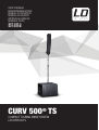 1
1
-
 2
2
-
 3
3
-
 4
4
-
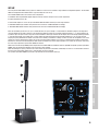 5
5
-
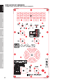 6
6
-
 7
7
-
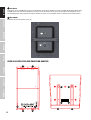 8
8
-
 9
9
-
 10
10
-
 11
11
-
 12
12
-
 13
13
-
 14
14
-
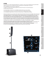 15
15
-
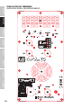 16
16
-
 17
17
-
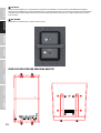 18
18
-
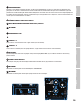 19
19
-
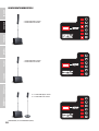 20
20
-
 21
21
-
 22
22
-
 23
23
-
 24
24
-
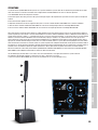 25
25
-
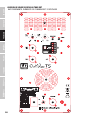 26
26
-
 27
27
-
 28
28
-
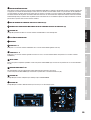 29
29
-
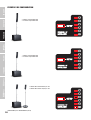 30
30
-
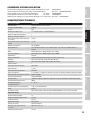 31
31
-
 32
32
-
 33
33
-
 34
34
-
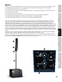 35
35
-
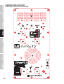 36
36
-
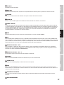 37
37
-
 38
38
-
 39
39
-
 40
40
-
 41
41
-
 42
42
-
 43
43
-
 44
44
-
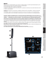 45
45
-
 46
46
-
 47
47
-
 48
48
-
 49
49
-
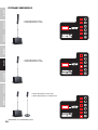 50
50
-
 51
51
-
 52
52
-
 53
53
-
 54
54
-
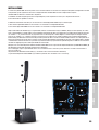 55
55
-
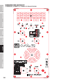 56
56
-
 57
57
-
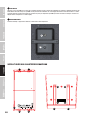 58
58
-
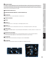 59
59
-
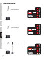 60
60
-
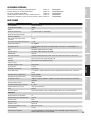 61
61
-
 62
62
-
 63
63
-
 64
64
-
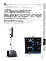 65
65
-
 66
66
-
 67
67
-
 68
68
-
 69
69
-
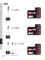 70
70
-
 71
71
-
 72
72
-
 73
73
-
 74
74
-
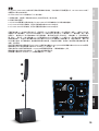 75
75
-
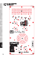 76
76
-
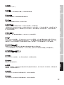 77
77
-
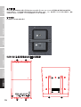 78
78
-
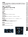 79
79
-
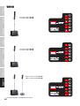 80
80
-
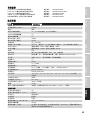 81
81
-
 82
82
-
 83
83
-
 84
84


LD Systems CURV 500 TS El manual del propietario
- Categoría
- Juegos de altavoces
- Tipo
- El manual del propietario
- Este manual también es adecuado para
en otros idiomas
Artículos relacionados
-
LD Systems CURV 500 PES Manual de usuario
-
LD Systems CURV 500 STS Manual de usuario
-
-
LD Systems CURV500IAMP 4-Channel Installation Amplifier Manual de usuario
-
LD Systems DAVE8XS Manual de usuario
-
-
-
LD Systems DAVE 8XS Manual de usuario
-
-