
P/NO : MFL68500202
INSTALLATION MANUAL
AIR
CONDITIONER
www.lg.com
Please read this installation manual completely before installing the product.
Installation work must be performed in accordance with the national wiring
standards by authorized personnel only.
Please retain this installation manual for future reference after reading it
thoroughly.
Single Inverter Outdoor Unit
ESPAÑOL
MFL68500202
ENGLISH

2
TIPS FOR SAVING ENERGY
• Excessive cooling may be harmful to your health and may consume more electricity.
• Block sunlight with blinds or curtains while you are operating the air conditioner.
• Keep doors or windows closed while you are operating the air conditioner.
• Adjust the direction of the air flow vertically or horizontally to circulate indoor air.
• Speed up the fan to cool or warm indoor air quickly, in a short period of time.
• Open windows regularly for ventilation as the indoor air quality may deteriorate if the air condition-
er is used for many hours.
• Clean the air filter once every 2 weeks. Dust and impurities collected in the air filter may block the
air flow or weaken the cooling / dehumidifying functions.
For your records
Staple your receipt to this page in case you need it to prove the date of purchase or for warranty
purposes. Write the model number and the serial number here:
Model number :
Serial number :
You can find them labeled on the side of each unit.
Dealer’s name :
Date of purchase :
Here are some tips that will help you minimize the power consumption when you use the air
conditioner. You can use your air conditioner more efficiently by referring to the instructions
below:
TIPS FOR SAVING ENERGY
ENGLISH

IMPORTANT SAFETY INSTRUCTIONS
3
ENGLISH
IMPORTANT SAFETY INSTRUCTIONS
READ ALL INSTRUCTIONS BEFORE USING THE APPLIANCE.
Always comply with the following precautions to avoid dangerous situations and ensure peak
performance of your product
WARNING
Serious injury or death can result if directions are ignores.
CAUTION
Minor injury or product damage can result if directions are ignored.
WARNING
• Installation or repairs made by unqualified persons can result in hazards to you and others.
Refrigeration work must be performed by a qualified person who is "F-Gas" registered.
• Installation work must be performed in accordance with the National Electric Code by quali-
fied and authorized personnel only.
• The information contained in the manual is intended for use by a qualified service technician
familiar with safety procedures and equipped with the proper tools and test instruments.
• Failure to carefully read and follow all instructions in this manual can result in equipment mal-
function, property damage, personal injury and/or death.
Installation
• Do not use a defective or underrated circuit breaker. Use the correctly rated breaker and fuse.
There is risk of fire or electric shock.
• For electrical work, contact the dealer, seller, a qualified electrician, or an Authorized Service
Center. Do not disassemble or repair the product by yourself. There is risk of fire or electric
shock.
• Always ground the product as per the wiring diagram. Do not connect the ground wire to gas
or water pipes lightening rod or telephone ground wire. There is risk of fire or electric shock.
• Install the panel and the cover of control box securely. There is risk of fire or electric shock
due to dust , water etc.
• Use the correctly rated breaker or fuse. There is risk of fire or electric shock.
• Do not modify or extend the power cable. If power cable is damaged or has deteriorated, then
it must be replaced. There is risk of fire or electric shock.
• For installation, removal or reinstall , always contact the dealer or an Authorized Service
Center. There is risk of fire, electric shock, explosion, or injury.
• Do not install the product on a defective installation stand. Be sure that the installation area
does not deteriorate with age. It may cause product to fall.
• Never install the outdoor unit on a moving base or a place from where it can fall down.
The falling outdoor unit can cause damage or injury or even death of a person.
• In outdoor unit the step-up capacitor supplies high voltage electricity to the electrical compo-
nents. Be sure to discharge the capacitor completely before conducting the repair work.
A charged capacitor can cause electrical shock.
• When installing the unit, use the installation kit provided with the product. Otherwise the unit
may fall and cause severe injury.
• Indoor/outdoor wiring connections must be secured tightly and the cable should be routed
properly so that there is no force pulling the cable from the connection terminals. Improper or
loose connections can cause heat generation or fire.
!
!
!
ENGLISH

4
IMPORTANT SAFETY INSTRUCTIONS
ENGLISH
• Safely dispose off the packing materials. Like screws, nails, batteries, broken things etc after
installation or svc and then tear away and throw away the plastic packaging bags. Children
may play with them and cause injury.
• Be sure to check the refrigerant to be used. Please read the label on the product. Incorrect
refrigerant used can prevent the normal operation of the unit.
•
Do not turn on the breaker or power under condition that front panel, cabinet, top cover, control box
cover are removed or opened. Otherwise, it may cause fire, electric shock, explosion or death.
•
Use a vacuum pump or Inert (nitrogen) gas when doing leakage test or air purge. Do not compress
air or Oxygen and do not use Flammable gases. Otherwise, it may cause fire or explosion.
- There is the risk of death, injury, fire or explosion.
Operation
• When the product is soaked (flooded or submerged) in water , contact an Authorized Service Center
for repair before using it again. There is risk of fire or eletric shock.
•
Be sure to use only those parts which are listed in the svc parts list. Never attempt to modify the equip-
ment. The use of inappropriate parts can cause an electrical shock, excessive heat generation or fire.
• Do not touch , operate, or repair the product with wet hands. Hold the plug by hand when taking it
out. There is risk of electric shock or fire.
• Do not place a heater or other heating appliances near the power cable. There is risk of fire and elec-
tric shock.
• Do not allow water to run into electric parts. Install the unit away from water sources. There is risk
of fire, failure of the product, or electric shock.
•
Do not store or use or even allow flammable gas or combustibles near the product. There is risk of fire.
• Do not use the product in a tightly closed space for a long time. Perform ventilation regularly.
Oxygen deficiency could occur and hence harm your health.
• Do not open the front grille of the product during operation. (Do not touch the electrostatic filter, if
the unit is so equipped.) There is risk of physical injury, electric shock, or product failure.
• If strange sound, smell or smoke comes from product. Immediately turn the breaker off or discon-
nect the power supply cable. There is risk of electric shock or fire.
• Ventilate the product room from time to time when operating it together with a stove, or heating
element etc. Oxygen deficiency can occur and hence harm your health.
• When the product is not to be used for a long time, disconnect the power supply plug or turn off
the breaker. There is risk of product damage or failure, or unintended operation.
• Take care to ensure that nobody especially kids could step on or fall onto the outdoor unit. This
could result in personal injury and product damage.
• Take care to ensure that power cable could not be pulled out or damaged during operation. There is
risk of fire or electric shock.
• Do not place ANYTHING on the power cable. There is risk of fire or electric shock.
• When flammable gas leaks, turn off the gas and open a window for ventilation before turning on the
product. Do not use the telephone or turn switches on or off. There is risk of explosion or fire.
CAUTION
Installation
• Two or more people must lift and transport the product. Avoid personal injury.
• Do not install the product where it will be exposed to sea wind (salt spray) directly. It may cause cor-
rosion on the product.
• Install the drain hose to ensure that the condensed water is drained away properly. A bad connec-
tion may cause water leakage.
!
ENGLISH

IMPORTANT SAFETY INSTRUCTIONS
5
ENGLISH
• Keep level even when installing the product. To avoid vibration or noise.
• Do not install the product where the noise or hot air from the outdoor unit could damage or disturb
the neighborhoods. It may cause a problem for your neighbors and hence dispute.
• Always check for gas (refrigerant) leakage after installation or repair of product. Low refrigerant lev-
els may cause failure of product.
• Please install safely at a place that can sufficiently endure the weight of the product.
If the strength is not sufficient, the product may fall and cause injury.
Operation
• Do not use the product for special purposes, such as preserving foods, works of art, etc. It is a con-
sumer air conditioner, not a precision refrigeration system. There is risk of damage or loss of proper-
ty.
• Do not block the inlet or outlet of air flow. It may cause product failure.
• Use a soft cloth to clean. Do not use harsh detergents, solvents or splashing water etc. There is risk
of fire, electric shock, or damage to the plastic parts of the product.
• Do not touch the metal parts of the product when removing the air filter. There is risk of personal
injury.
• Do not step on or put anyting on the product. (outdoor units) There is risk of personal injury and fail-
ure of product.
• Always insert the filter securely after cleaning. Clean the filter every two weeks or more often if
necessary. A dirty filter reduces the efficiency.
• Do not insert hands or other objects through the air inlet or outlet while the product is operating.
There are sharp and moving parts that could cause personal injury.
• Be cautious when unpacking and installing the product. Sharp edges could cause injury.
• If the refrigerant gas leaks during repair, do not touch the leaking refrigerant gas. The refrigerant
gas can cause frostbite (cold burn).
• Do not tilt the unit when removing or uninstalling it. The condensed water inside can spill.
• Do not mix air or gas other than the specified refrigerant used in the system. If air enters the refrig-
erant system, an excessively high pressure results, causing equipment damage or injury.
• If the refrigerant gas leaks during the installation, ventilate the area immediately. Otherwise it can be
harmfull for your health.
• Dismantling the unit, treatment of the refrigerant oil and eventual parts should be done in accor-
dance with local and national standards.
• Replace all batteries in the remote control with new ones of the same type. Do not mix old and new
batteries or different types of batteries. There is risk of fire or product failure.
• Do not recharge or disassemble the batteries. Do not dispose off batteries in a fire. They may burn
or explode.
• If the liquid from the batteries gets onto your skin or clothes, wash it well with clean water. Do not
use the remote if the batteries have leaked. The chemicals in batteries could cause burns or other
health hazards.
• If you eat the liquid from the batteries, brush your teeth and see doctor. Do not use the remote if
the batteries have leaked. The chemicals in batteries could cause burns or other health hazards.
• Do not let the air conditioner run for a long time when the humidity is very high and a door or a win-
dow is left open. Moisture may condense and wet or damage furniture.
• Do not expose your skin or kids or plants to the cool or hot air draft. This could harm to your health.
• Do not drink the water drained from the product. It is not sanitary and could cause serious health
issues.
• Use a firm stool or ladder when cleaning, maintaining or repairing the product at height. Be careful
and avoid personal injury.
ENGLISH

6
TABLE OF CONTENTS
ENGLISH
2 TIPS FOR SAVING ENER-
GY
7 INSTALLATION
8 INSTALLATION OF OUT-
DOOR UNIT
9 CONNECTING PIPES
9 Preparation of Piping
10 Connection of piping - Outdoor
11 Forming the piping
12 WIRING CONNECTION
12 Electrical Wiring
12 Connecting Cables between Indoor Unit
and Outdoor Unit
14 Connecting the cable to Outdoor Unit
15 LEAKAGE TEST AND
EVACUATION
15 Preparation
15 Leakage test
16 Evacuation
17 TEST RUNNING
19 INSTALLATION GUIDE AT
THE SEASIDE
19 SEASONAL WIND AND
CAUTIONS IN WINTER
TABLE OF CONTENTS
ENGLISH

INSTALLATION
7
more than
30cm
more than
30cm
Figure FigureName
Screw driver
Electric drill
Measuring tape, Knife
Hole core drill
Spanner
Torque wrench
Multi-meter
Hexagonal wrench
Ammeter
Gas-leak detector
Thermometer,
Level
Flaring tool set
Name
Installation Tools
INSTALLATION
ENGLISH

8
INSTALLATION OF INDOOR, OUTDOOR UNIT
ENGLISH
- If an awning is built over the unit to prevent direct
sunlight or rain exposure, make sure that heat
radiation from the condenser is not restricted.
- Ensure that the spaces indicated by arrows
around front, back and side of the unit are
respected.
- Do not place animals and plants in the path of the
warm air.
- Take the air conditioner weight into account and
select a place where noise and vibration are mini-
mum.
- Select a place so that the warm air and noise from
the air conditioner do not disturb neighbors.
You need to select adequate installation location considering the following conditions, and make
sure to acquire the consent of the user.
- Select a place that can sufficiently endure the weight and vibration of the outdoor unit and
where even installation is possible.
- Select a place that has no direct impact of snow or rain
- Select a place with no danger of snowfall or icicle drop
- Select a place without weak floor or base such as decrepit part of the building or with a lot of
snow accumulation
- Install at a place with fluent water draining to prevent damage from localized heavy rain and
avoid frequent flooded area.
If installed tube is shorter than 7.5 m,
additional charging is not necessary.
Additional Refrigerant
= [A-7.5 (m)] x Additional refrigerant (g/m)
INSTALLATION OF OUTDOOR UNIT
Indoor unit
A
Model
Pipe Size mm(inch) Length A(m) Elevation B(m)
Additional
refrigerant
(g/m)
Gas Liquid Standard Max. Standard Max.
Ø15 88 (5/8) Ø9 52 (3/8) 7 5 40 5 30 40
AVUW36GM1S0
Ø15 88 (5/8) Ø9 52 (3/8) 7 5 75 5 30 40
AVUW60LM2S0
...
B
Indoor unit
A
B
More than
300mm
Fence or
obstacles
More than 700mm
More than 600mm
More than
300mm
More than
300mm
Sunroof
Installation Places
ENGLISH
Piping length and the elevation

CONNECTING PIPESINSTALLATION OF INDOOR, OUTDOOR UNIT
9
ENGLISH
Main cause of gas leakage is defect in flaring work. Carry out correct flaring work in the following
procedure.
C
ut the pipes and the cable.
- Use the accessory piping kit or the pipes pur-
chased locally.
- Measure the distance between the indoor
and the outdoor unit.
- Cut the pipes a little longer than measured
distance.
- Cut the cable 1,5m longer than the pipe
length.
B
urrs removal
- Completely remove all burrs from the cut
cross section of pipe/tube.
- Put the end of the copper tube/pipe to down-
ward direction as you remove burrs in order
to avoid to let burrs drop in the tubing.
P
utting nut on
- Remove flare nuts attached to indoor and
outdoor units, than put them on pipe/tube
having completed burr removal.
(Not possible to put them on after flaring
work)
F
laring w ork
- Carry out flaring work using dedicated flaring
tool for R-410A as shown below.
Firmly hold copper tube in a bar(or clamp) as
indicated dimension in the table above.
C
heck
- Compare the flared work with figure below.
- If flare is noted to be defective, cut off the
flared section and do flaring work again.
Bar
Copper pipe
Clamp handle
Red arrow mark
Cone
Yoke
Handle
Bar
"A"
Inclined
Inside is shining without scratches.
Smooth all round
Even length
all round
Surface
damaged
Cracked Uneven
thickness
= Improper flaring =
Flare nut
Copper tube
Pipe
Reamer
Point down
Copper
tube
90°
Slanted Uneven Rough
Preparation of Piping
Outside diameter "A"
mm inch mm
Ø6.35 1/4 1.1~1.3
Ø9.52 3/8 1.5~1.7
Ø12.7 1/2 1.6~1.8
Ø15.88 5/8 1.6~1.8
CONNECTING PIPES
ENGLISH

10
CONNECTING PIPES
ENGLISH
Connection of piping -
Outdoor
- Align the center of the piping and sufficiently
tighten the flare nut by hand.
- Finally, tighten the flare nut with torque
wrench until the wrench clicks.
When tightening the flare nut with torque
wrench ensure the direction for tightening
follows the arrow on the wrench.
* When tighten the pipe, hold the haxagonal
body.
- When connecting in a downward direction,
knock out the knock-out hole of the base
pan. (refer to figure 2)
Preventing foreign objects from entering
(Figure3)
- Plug the pipe through-holes with putty or
insulation material(procured locally)to stop up
all gaps,as shown in the figure 3.
Continuous
Torque
wrench
(250mm)
Torque
wrench
(250mm)
Knock-out Base pan
<Figure 2>
Gas side piping
Liquid side piping
Drain hose
Connecting wire
Connection pipe
<Figure 3>
Resin, Clay, Putty or insulating material
(produced locally)
Insects or small animals entering the out-
door unit may cause a short circuit in the
electrical box.
CAUTION
!
Outside diameter
Torque
mm inch N·m
Ø6.35 1/4 16±2
Ø9.52 3/8
Ø12.7 1/2
Ø15.88 5/8
38±4
55±6
75±7
Torque
wrench
Contin
-uous
ENGLISH

CONNECTING PIPES
11
ENGLISH
Forming the piping
Form the piping by wrapping the connecting
portion of the indoor unit with insulation mate-
rial and secure it with two kinds of vinyl tape.
- If you want to connect an additional drain
hose, the end of the drain outlet should be
routed above the ground. Secure the drain
hose appropriately.
In cases where the outdoor unit is installed
below the indoor unit perform the following.
1 Tape the piping, drain hose and connecting
cable from down to up.
2 Secure the tapped piping along the exterior
wall using saddle or equivalent.
In cases where the Outdoor unit is installed
above the Indoor unit perform the following.
1 Tape the piping and connecting cable from
down to up.
2 Secure the taped piping along the exterior
wall. Form a trap to prevent water entering
the room.
3 Fix the piping onto the wall by saddle or
equivalent.
Trap
Plastic
band
Seal a small
opening around
the pipings with
gum type sealer.
TrapTrapTrap
Seal a small opening Seal a small opening
around the pipings around the pipings
with gum type sealer.with gum type sealer.
Seal a small opening
around the pipings
with gum type sealant.
OUTDOOR
UNIT
OUTDOOROUTDOOR
UNITUNIT
OUTDOOR
UNIT
• Trap is required to prevent water from entering
into electrical parts.
Taping
Drain hose
Pipings
Connecting
cable
Power supply
cord
PlasticPlastic
bandband
Plastic
band
Seal a small
opening around
the pipings with
gum type sealer.
Seal a small
opening around
the pipings with
gum type sealant.
Trap
Seal a small opening
around the pipings
with gum type sealer.
OUTDOOR
UNIT
OUTDOOR
UNIT
OUTDOOR
UNIT
ENGLISH

12
WIRING CONNECTION
ENGLISH
Connecting Cables between Indoor Unit and Outdoor Unit
- Connect the wires to the terminals on the control board individually according to the outdoor
unit connection.
- Ensure that the color of the wires of outdoor unit and the terminal No. are the same as those of
indoor unit respectively
Outdoor
Indoor
Main
power source
Switch box
ELCB
Model Phase(Ø) ELCB
AVUW36GM1S0
1 25A
3 20A
1(L) 2(N) 1(L) 2(N) 3
POWER SUPPLY TO INDOOR UNIT
AVUW60LM2S0
AVUW36GM1S0
Electrical Wiring
Perform the electrical wiring work according
to the electrical wiring connection.
- All wiring must comply with local require-
ments.
- Select a power source that is capable of sup-
plying the current required by the air condi-
tioner.
- Use a recognized ELCB(Electric Leakage
Circuit Breaker) between the power source
and the unit. A disconnection device to ade-
quately disconnect all supply lines must be
fitted.
- Model of circuit breaker recommended by
authorized personnel only
WIRING CONNECTION
AVUW60LM2S0
RS TN 1(L) 2(N) 3
TINU ROODNI OTYLPPUS REWOP
ENGLISH

WIRING CONNECTION
13
CAUTION
!
The power cord connected to the outdoor unit should comply to IEC 60245 or HD 22.4 S4
(This equipment shall be provided with a cord set complying with the national regulation.)
GN/YL
1 Phase(Ø)
20mm
3 Phase(Ø)
20mm
GN/YL
Model Phase(Ø) Area(mm
2
)
1 2.5
3 2.5
!
AVUW36GM1S0
AVUW60LM2S0
NORMAL CROSS-SECTIONAL AREA
The connecting cable connected to the outdoor unit should comply to IEC 60245 or HD
22.4 S4 (This equipment shall be provided with a cord set complying with the national reg-
ulation.)
20mm
GN/YL
When the connection line between the indoor unit and outdooor unit is over 40m, connect
the telecommunication line and power line separately.
If the supply cord is damaged, it must be replaced by a special cord or assembly available
from the manufacturer of its service agent.
P
recautions w hen laying pow er w iring
Use round pressure terminals for connections to the power terminal block.
Round pressure terminal
Power wire
When none are available, follow the instructions below.
- Do not connect wiring of different thicknesses to the power terminal block. (Slack in the power
wiring may cause abnormal heat.)
- When connecting wiring which is the same thickness, do as shown in the figure below.
WARNING
Make sure that the screws of the terminal are free from looseness.
Model Phase(Ø) Area(mm
2
)
1 0.75
3 1.00
AVUW36GM1S0
AVUW60LM2S0
NORMAL CROSS-SECTIONAL AREA
ENGLISH

14
WIRING CONNECTION
ENGLISH
Connecting the cable to Outdoor Unit
Remove the side panel for wiring connection.
Use the cord clamp to fix the cord.
Earthing work
- Case 1 : Terminal block of Outdoor Unit have mark.
Connect the cable of diameter 1,6mm
2
or more to the earthing terminal provided in the
control box and do earthing.
- Case 2 : Terminal block of Outdoor Unit don't have mark.
Connect the cable of diameter 1,6mm
2
or more, to the panel of control box, marked as
and fasten with earth screw
CAUTION
!
ţ5IFDJSDVJUEJBHSBNJTOPUTVCKFDUUPDIBOHFXJUIPVUOPUJDF
ţ#FTVSFUPDPOOFDUXJSFTBDDPSEJOHUPUIFXJSJOHEJBHSBN
ţ$POOFDUUIFXJSFTżSNMZTPUIBU5IFZXPOŜUCFQVMMFEPVUFBTJMZ
ţ$POOFDUUIFXJSFTBDDPSEJOHUPDPMPSDPEFTCZSFGFSSJOHUIFXiring diagram.
ţ5IF1PXFSDPSEDPOOFDUFEUPUIFVOJUTIPVMECFTFMFDUFEBDDPSEJOHUPUIFTQFDJżDBUJPOT
on 13 page.
* Make sure the rubber
bushes arF1rPQFSMZ
used in knock-out holes
after connecting main
1ower cable
Connecting
cable terminal
1ower cord
terminal
Cord clamp
Cord clamp
Connecting cable terminal
1Pwer cord terminal
Cord clamp
* Make sure the rubber bushes are
QSPQFSMZVTFEJOLOPDLPVUIPMFTBGUFS
connecting main power.
AVUW36GM1S0AVUW60LM2S0
ENGLISH

LEAKAGE TEST AND EVACUATION
15
ENGLISH
Preparation
Check that each tube(both liquid and gas side
tubes) between the indoor and outdoor units
have been properly connected and all wiring
for the test run has been completed. Remove
the service valve caps from both the gas and
the liquid side on the outdoor unit. Check that
both the liquid and the gas side service valves
on the outdoor unit are kept closed at this
stage.
Leakage test
Connect the manifold valve(with pressure
gauges) and dry nitrogen gas cylinder to this
service port with charge hoses.
CAUTION
Be sure to use a manifold valve for leakage
test. If it is not available, use a stop valve for
this purpose. The "Hi" knob of the manifold
valve must always be kept close.
- Pressurize the system to no more than
3,0 MPa with dry nitrogen gas and close
the cylinder valve when the gauge read-
ing reached 3,0 MPa. Next test for leaks
with liquid soap.
!
CAUTION
To avoid nitrogen entering the refrigerant
system in a liquid state, the top of the
cylinder must be higher than its bottom
when you pressurize the system. Usually,
the cylinder is used in a vertical standing
position.
!
- Do a leakage test of all joints of the
tubing(both Indoor unit and outdoor unit) and
both gas and liquid side service valves.
Bubbles indicate a leak. Be sure to wipe off
the soap with a clean cloth.
- After the system is found to be free of leaks,
relieve the nitrogen pressure by loosening
the charge hose connector at the nitrogen
cylinder. When the system pressure is
reduced to normal, disconnect the hose from
the cylinder.
Air and moisture remaining in the refrigerant
system have undesirable effects as indicated
below.
- Pressure in the system rises.
- Operating current rises.
- Cooling(or heating) efficiency drops.
- Moisture in the refrigerant circuit may freeze
and block capillary tubing.
- Water may lead to corrosion of parts in the
refrigeration system.
Therefore, the indoor/outdoor unit and con-
necting tube must be checked for leak tight,
and vacuumed to remove incondensible gas
and moisture in the system.
Charge hose
Indoor unit
Outdoor unit
Manifold valve
Pressure
gauge
Nitrogen gas
cylinder(in vertical
standing position)
Lo Hi
LEAKAGE TEST AND EVACUATION
ENGLISH

16
LEAKAGE TEST AND EVACUATION
ENGLISH
- When the desired vacuum is reached, close
the "Lo and Hi" knob of the manifold valve
and stop the vacuum pump.
Required time for evacuation when 30 gal/h
vacuum pump is used
If tubing length is
less than10 m (33 ft)
If tubing length is
longer than 10 m (33 ft)
30 min. or more 60 min. or more
0.67 kPa or less
- With a service valve wrench, turn the valve
stem of liquid side valve counter-clockwise to
fully open the valve.
- Turn the valve stem of gas side valve counter-
clockwise to fully open the valve.
- Loosen the charge hose connected to the gas
side service port slightly to release the pressure,
then remove the hose.
- Replace the flare nut and its bonnet on the gas
side service port and fasten the flare nut secure-
ly with an adjustable wrench. This process is
very important to prevent leakage from the sys-
tem.
- Replace the valve caps at both gas and liquid
side service valves and fasten them tightly.
This completes air purging with a vacuum pump.
The air conditioner is now ready to test run.
Indoor unit
Outdoor unit
Lo Hi
Manifold valve
Vacuum pump
Open
Open
Pressure
gauge
Finishing the job
Evacuation
- Connect the charge hose end described in
the preceding steps to the vacuum pump to
evacuate the tubing and indoor unit.
Confirm the "Lo and Hi" knob of the manifold
valve is open. Then, run the vacuum pump.
The operation time for evacuation varies with
tubing length and capacity of the pump. The
following table shows the time required for
evacuation.
ENGLISH

TEST RUNNING
17
ENGLISH
- The initial power supply must provide at least 90 % of the rated voltage.
Otherwise, the air conditioner should not be operated.
- The test run is started by pressing the room temperature checking button and down timer but-
ton for 3 seconds at the same time.
- To cancel the test run, press any button.
Check the following items when installation is complete
- After completing work, be sure to measure and record trial run properties, and store measured
data, etc.
- Measuring items are room temperature, outside temperature, suction temperature, blow out
temperature, wind velocity, wind volume, voltage, current, presence of abnormal vibration and
noise, operating pressure, piping temperature, compressive pressure.
- As to the structure and appearance, check following items.
- Connect the power supply cord to the independent power supply.
Circuit breaker is required.
- Operate the unit for 15 minutes or more.
Precautions In Test Running
Connection of power supply
Evaluation of the performance
CAUTION
For test run, carry out the cooling operation firstly even during heating season. If heating operation
is carried out firstly, it leads to the trouble of compressor. Then attention must be paid.
Carry out the test run more than 5 minutes without fail.
(Test run will be cancelled 18 minutes later automatically)
!
□Is the circulation of air adequate?
□Is the draining smooth?
□Is the heat insulation completed
(refrigerant and drain piping)?
□Is there any leakage of refrigerant?
□Is the remote controller switch operated?
□Is there any faulty wiring?
□Are not terminal screws loosened?
M4......118 N·cm {12 kgf·cm}
M5......196 N·cm {20 kgf·cm}
M6......245 N·cm {25 kgf·cm}
M8......588 N·cm {60 kgf·cm}
- Measure the temperature of the intake and discharge air.
- Ensure the difference between the intake temperature and the discharge one is more than 8 °C
(Cooling) or reversely (Heating).
TEST RUNNING
ENGLISH

18
TEST RUNNING
HAND OVER
Teach the customer the operation and maintenance procedures, using the operation manual
(air filter cleaning, temperature control, etc.).
CAUTION
After the confirmation of the above conditions, prepare the wiring as follows:
1
Never fail to have an individual power specialized for the air conditioner. As for the method of
wiring, be guided by the circuit diagram pasted on the inside of control box cover.
2
Provide a circuit breaker switch between power source and the unit.
3
The screw which fasten the wiring in the casing of electrical fittings are liable to come loose
from vibrations to which the unit is subjected during the course of transportation. Check
them and make sure that they are all tightly fastened. (If they are loose, it could give rise to
burn-out of the wires.)
4
Specification of power source
5
Confirm that electrical capacity is sufficient.
6
Be sure that the starting voltage is maintained at more than 90 percent of the rated voltage
marked on the name plate.
7
Confirm that the cable thickness is as specified in the power sources specification.
(Particularly note the relation between cable length and thickness.)
8
Never fail to equip a leakage breaker where it is wet or moist.
9
The following troubles would be caused by voltage drop-down.
- Vibration of a magnetic switch, damage on the contact point there of fuse breaking, distur-
bance to the normal function of a overload protection device.
- Proper starting power is not given to the compressor.
!
ENGLISH

19
ENGLISH
INSTALLATION GUIDE AT THE SEASIDE
If the outdoor unit is to be installed close to
the seaside, direct exposure to the sea wind
should be avoided. Install the outdoor unit on
the opposite side of the sea wind direction.
In case, to install the outdoor unit on the
seaside, set up a windbreak not to be exposed
to the sea wind.
- It should be strong enough like concrete to
prevent the sea wind from the sea.
- The height and width should be more than
150% of the outdoor unit.
- More than 70cm of space should be kept
between outdoor unit and the windbreak for
easy air flow.
Place with fluent water draining
- Install at a place with fluent water draining to
prevent damage from localized heavy rain and
avoid frequent flooded area.
SEASONAL WIND AND
CAUTIONS IN WINTER
- Sufficient measures are required in a snow
area or severe cold area in winter so that
product can operate well.
- Get ready for seasonal wind or snow in win-
ter even in other areas.
- Install a suction and discharge duct not to let
in snow or rain.
- Install the outdoor unit not to come in contact
with snow directly. If snow piles up and
freezes on the air suction hole, the system
may malfunction. If it is installed at snowy
area, attach the hood to the system.
- Install the outdoor unit at the higher installa-
tion console by 50cm than the average snow-
fall (annual average snowfall) if it is installed
at the area with much snowfall.
- Where snow accumulated on the upper part
of the Outdoor Unit by more than 10cm,
always remove snow for operation.
Sea wind
Sea wind
Sea wind
Windbreak
• Periodic ( more than once/year ) clean-
ing of the dust or salt particles stuck on
the heat exchanger by using water.
• Air conditioners should not be installed
in areas where corrosive gases, such as
acid or alkaline gas, are produced.
• Do not install the product where it could
be exposed to sea wind (salty wind)
directly. It can result corrosion on the
product. Corrosion, particularly on the
condenser and evaporator fins, could
cause product malfunction or inefficient
performance.
• If outdoor unit is installed close to the
seaside, it should avoid direct exposure
to the sea wind. Otherwise it needs
additional anticorrosion treatment on the
heat exchanger.
CAUTION
!
Selecting the location (Outdoor Unit)
INSTALLATION GUIDE
AT THE SEASIDE
ENGLISH

MANUAL DE INSTALACIÓN
AIRE
ACONDICIONADO
www.lg.com
Por favor, lea completamente este manual antes de instalar el producto.
El trabajo de instalación debe realizarse conforme a los estándares de cableado
nacionales por el personal autorizado.
Una vez haya leído el manual atentamente, guárdelo para futuras referencias.
Single inverter
Traducción de las instrucciones originales
ESPAÑOL

2
CONSEJOS PARA AHORRAR ENERGÍA
• No enfríe excesivamente los espacios interiores. Puede ser nocivo para su salud y consumirá más
electricidad.
• Evite el paso de la luz solar con persianas o cortinas cuando esté utilizando el aire acondicionado.
• Mantenga las puertas y ventanas bien cerradas mientras tenga en funcionamiento el aire acondi-
cionado.
• Ajuste la dirección del flujo de aire vertical u horizontalmente para que circule el aire en el interior.
• Aumente la velocidad del ventilador para enfriar o calentar el aire interior con rapidez y en periodo
corto de tiempo.
• Abra las ventanas con regularidad para ventilar, porque la calidad del aire interior puede deteriorar-
se si se utiliza el aire acondicionado durante muchas horas.
• Limpie el filtro del aire cada dos semanas. El polvo y las impurezas acumulados en el filtro de aire
pueden bloquear el flujo de aire o debilitar las funciones de refrigeración / deshumidificación.
Como referencia
Grape el justificante de compra en esta página, en el caso de necesitarlo para probar la fecha de la
compra o a efectos de garantía. Escriba aquí el número de modelo y el número de serie:
Número de modelo :
Número de serie :
Puede encontrarlos en la etiqueta situada en el lateral de cada unidad.
Nombre del distribuidor :
Fecha de la compra :
Estos consejos le ayudarán a reducir el consumo de energía cuando utilice el aire acondicionado.
Podrá utilizar el aparato de aire acondicionado de forma eficiente siguiendo estas instrucciones:
CONSEJOS PARA AHORRAR ENERGÍA
ESPAÑOL

INSTRUCCIONES DE SEGURIDAD IMPORTANTES
3
ESPAÑOL
INSTRUCCIONES DE SEGURIDAD IMPORTANTES
LEA TODAS LAS INSTRUCCIONES ANTES DE UTILIZAR EL APARATO
Cumpla con las siguientes precauciones para evitar situaciones de peligro y garantizar un funciona-
miento óptimo de su producto.
ADVERTENCIA
Puede sufrir lesiones de gravedad o mortales si ignora las instrucciones
PRECAUCIÓN
Puede sufrir lesiones menores o dañar el producto si ignora las instrucciones
ADVERTENCIA
• Las instalaciones o reparaciones realizadas por personas no cualificadas pueden dar lugar a peligros para
usted y otras personas.
• Las tareas de instalación deben realizarse de acuerdo con el Código Eléctrico Nacional y sólo puede lle-
varlas a cabo personal cualificado y autorizado.
• La información de este manual está dirigida a personal técnico cualificado, familiarizado con los procedi-
mientos de seguridad y equipado con las herramientas e instrumentos de prueba adecuados.
• Lea detenidamente y cumpla con todas las instrucciones de este manual. De lo contrario, el aparato
podría no funcionar correctamente, o producirse lesiones graves o mortales y daños materiales.
Instalación
• No utilice un cortacircuitos defectuoso o con una capacidad nominal inferior a la necesaria. Utilice un cor-
tacircuitos y un fusible con una capacidad nominal correcta. Existe el riesgo de fuego o descargas eléctri-
cas.
• Para los trabajos eléctricos, póngase en contacto con el distribuidor, el vendedor, un electricista cualifica-
do o un Servicio técnico autorizado. No desmonte ni repare el producto. Existe el riesgo de fuego o des-
cargas eléctricas.
• Conecte una toma de tierra al producto como muestra el diagrama de cableado. No conecte la toma de
tierra a tuberías de gas o agua, un tubo de pararrayos o un cable de toma de tierra de teléfono. Existe el
riesgo de fuego o descargas eléctricas.
• Instale el panel y la cubierta de la caja de control con seguridad. Existe riesgo de fuego o descargas eléc-
tricas debido al polvo, agua, etc…
• Utilice un cortacircuitos o fusible con la clasificación adecuada. Existe el riesgo de fuego o descargas
eléctricas.
• No modifique ni alargue el cable de alimentación. Si el cable de alimentación tiene arañazos o se ha
dañado el aislante o está deteriorado, deberá sustituirlo. Existe el riesgo de fuego o descargas eléctricas.
• Para la instalación, retirada o reinstalación, póngase en contacto con el distribuidor o un centro de servi-
cio técnico autorizado. Existe el riesgo de fuego, descargas eléctricas, explosion o heridas.
•
No instale el producto en una base de instalación defectuosa. Asegúrese de que el área de instala-
ción no se deteriora con el tiempo. Podría hacer que el producto se caiga.
•
Nunca instale la unidad exterior en una base móvil o en un lugar desde donde pueda caerse. La
caída de la unidad exterior puede causar daños materiales o personales, incluso la muerte de una
persona.
•
En la unidad exterior, el condensador de aumento proporciona electricidad de alto voltaje a los
componentes eléctricos. Asegúrese de descargar el condensador completamente antes de realizar
algún trabajo de reparación. Un condensador cargado puede causar descargas eléctricas.
!
!
!
ESPAÑOLESPAÑOL

4
INSTRUCCIONES DE SEGURIDAD IMPORTANTES
ESPAÑOL
•
Al instalar la unidad, use el kit de instalación proporcionado con el producto. En caso contrario la
unidad podría caerse y causar heridas serias.
•
Las conexiones de cableado de interior/exterior deben fijarse fuertemente y el cable debe dispo-
nerse correctamente para que no haya fuerzas que tiren del cable en los terminales de conexión.
Una conexiones inadecuadas o flojas pueden generar calor o fuego.
•
Deshágase de forma segura de los materiales de embalaje. Como los tornillos, clavos, baterías,
elementos rotos, etc… tras la instalación o reparación y, a continuación, rompa y deshágase de las
bolsas de plástico del embalaje. Los niños podrían jugar con ellos y herirse.
•
Asegúrese de comprobar el refrigerante usado. Lea la etiqueta del producto. Usar un refrigerante
incorrecto puede impedir el funcionamiento normal de la unidad.
• No encienda el disyuntor ni la alimentación en caso de que el panel frontal, el gabinete, la cubierta
superior o la cubierta de la caja de control se hayan extraído o abierto. De lo contrario, podría pro-
ducirse un incendio, una descarga eléctrica, una explosión o incluso la muerte.
• Utilice una bomba al vacío o gas inerte (nitrógeno) cuando proceda a pruebas de escape o purga de
aire. No comprima ni el aire ni el oxígeno, ni utilice gases inflamables. En caso contrario, podría
causar un incendio o una explosión.
- Existe riesgo de muerte, lesión, incendio o explosión.
Funcionamiento
• Cuando el producto se moje (se inunda o se sumerja) en agua, póngase en contacto con un centro de servicio
técnico para repararlo antes de usarlo de nuevo. Existe riesgo de fuego o descargas eléctricas.
• Asegúrese de usar solamente los componentes de la lista de componentes svc. No intente nunca modificar el
equipo. Usar componentes inadecuados puede causar descargas eléctricas, generar un calor excesivo o fuego.
• No toque, opera ni repare el producto con las manos mojadas. Al desenchufar el equipo sujete el enchufe y no
el cable. Existe riesgo de descargas eléctricas o fuego.
• No coloque un calefactor u otros dispositivos de calor cerca del cable de alimentación. Existe riesgo de fuego o
descargas eléctricas.
• Evite que entre agua en las partes eléctricas. Instale la unidad alejada de las fuentes de agua. Existe riesgo de
fuego, averías en el producto o descargas eléctricas.
•
No guarde ni use, ni siquiera permita gas inflammable o combustibles cerca del producto. Existe riesgo de fuego.
• No utilice el producto en un lugar muy cerrado durante un largo periodo de tiempo. Ventile regularmente. Podría
aparecer deficiencia de oxígeno y por lo tanto dañar su salud.
• No abra la rejilla frontal del producto mientras esté en funcionamiento. (No toque el filtro electrostático en caso
de que la unidad disponga de uno.) Existe riesgo de heridas, descargas eléctricas o averías en el producto.
• Si el producto emite ruidos, olores o humo extraños. Interrumpa la corriente con el cortacorrientes inmediata-
mente o desenchufe el cable de alimentación. Existe riesgo de descargas eléctricas o fuego.
• Ventile la sala del producto de vez en cuando mientras lo utilice con una estufa, dispositivos de calor, etc...
Podría aparecer deficiencia de oxígeno y por lo tanto dañar su salud.
• Cuando no se vaya a usar el producto durante un largo periodo de tiempo, desenchufe el cable de alimentación
o interrumpa la alimentación con el cortacircuitos. Existe riesgo de daños o averías en el producto o de un fun-
cionamiento no deseado.
• Tenga cuidado de asegurar que nadie, en especial los niños, podría pisar o caerse sobre la unidad exterior.
Podría causar heridas o daños en el producto.
• Tenga cuidado para asegurarse de que el cable no pueda desenchufarse de un tirón ni resultar dañado durante
el funcionamiento. Existe el riesgo de fuego o descargas eléctricas.
• No coloque NADA sobre el cable de alimentación. Existe el riesgo de fuego o descargas eléctricas.
•
Cuando haya fugas de gas inflamable, corte el circuito de gas y abra una ventana para ventilar la sala antes de encen-
der el producto. No utilice el teléfono ni encienda o apague interruptores. Existe riesgo de explosión o fuego.
PRECAUCIÓN
Instalación
• Para mover y transportar el producto son necesarias dos personas. Evitará daños personales.
• No instale el producto en un lugar donde pueda estar expuesto al viento marino (viento salado) directamente.
Podría causar corrosión en el producto.
!
ESPAÑOL

INSTRUCCIONES DE SEGURIDAD IMPORTANTES
5
ESPAÑOL
• Instale la manguera de drenaje para asegurarse de que el agua condensada se drena adecuadamente. Una mala
conexión podría causar fugas de agua.
• Mantenga el equipo nivelado mientras lo instala. Para evitar vibraciones o ruidos.
• No instale el producto donde el ruido o el aire caliente de la unidad exterior podría dañar o molestar a los veci-
nos. Podría causar un problema para sus vecinos y, por lo tanto, tensiones.
• Compruebe siempre que no hay fugas de gas (refrigerante) tras instalar o reparar el producto. Unos niveles
bajos de refrigerante podrían causar averías en el producto.
• Haga la instalación en un lugar estable que pueda resistir el peso del producto. Si la resistencia no es suficiente,
el producto podría caer y causarle lesiones.
Funcionamiento
• No utilice el producto para fines especiales, como conservar comida, obras de arte, etc… Es un aire acondicio-
nado doméstico, no un sistema de refrigeración de precisión. Existe riesgo de daños o pérdidas de propiedad.
• No bloquee la entrada o la salida del caudal de aire. Podría causar averías en el producto.
• Utilice un paño suave para limpiarlo. No use detergentes agresivos, disolventes ni lo salpique de agua. Existe
riesgo de fuego, descargas eléctricas o daños en las partes de plástico del producto.
• Nunca toque las partes metálicas del producto al retirar el filtro de aire. Existe riesgo de daños personales.
• No pise ni coloque nada sobre el producto. (unidades de exterior) Existe riesgo de daños personales y de avería
del producto.
• Inserte siempre el filtro con seguridad una vez limpio. Limpie el filtro cada dos semanas o con mayor frecuencia
si es necesario. Un filtro sucio reduce la eficacia.
• No inserte las manos ni ningún otro objeto por la entrada o la salida de aire mientras el producto esté funcionan-
do. Existen partes afiladas y móviles que podrían causar heridas.
• Tenga cuidado al desembalar e instalar el producto. Los bordes afilados podrían causar heridas.
• Si el gas refrigerante se escapa durante una reparación no toque el gas refrigerante de la fuga. El gas refrigeran-
te podría causar quemaduras por frío.
• No incline la unidad al retirarla o desinstalarla. El agua condensada del interior podría derramarse.
• No mezcle aire o gas distintos al refrigerante específico usado en el sistema. Si el aire entra en el sistema de
refrigerante hará que la presión suba excesivamente, causando daños en el quipo o daños personales.
• Si el gas refrigerante se escapa durante la instalación, ventile el área inmediatamente. De no hacerlo podría ser
peligroso para su salud.
• El desmontaje de la unidad, el tratamiento del aceite refrigerante y componentes debe realizarse según los
estándares locales y nacionales.
• Cambie las baterías del control remoto por unas nuevas del mismo tipo. No mezcle baterías nuevas y viejas ni
de tipos diferentes. Existe riesgo de fuego o averías en el producto.
• No recargue ni desmonte las baterías. No se arroje las baterías al fuego. Podrían arder o explotar.
• Si el líquido de las baterías entra en contacto con la piel o la ropa, lave la zona con abundante agua. No utilice el
control remoto si las baterías tienen fugas. Los productos químicos de las baterías podrían causar quemaduras
u otros riesgos para su salud.
•
Si ingiere el líquido de las baterías, lávese los dientes y consulte a un médico. No utilice el control remoto si las baterí-
as tienen fugas. Los productos químicos de las baterías podrían causar quemaduras u otros riesgos para su salud.
• Evite que el aire acondicionado funcione durante un largo periodo de tiempo cuando la humedad sea alta y se
haya dejado abierta una ventana o puerta. La humedad puede condensarse y mojar o dañar los muebles.
• No exponga la piel o los niños o plantas a la corriente de aire frío o caliente. Podría dañar su salud.
• No beba el agua de drenaje del producto. No es potable y podría causar problemas de salud serios.
• Utilice una banqueta estable o una escalera para la limpieza, el mantenimiento o reparación de un producto que
se encuentre en alto. Tenga cuidado para evitar daños personales.
ESPAÑOLESPAÑOL

6
TABLA DE CONTENIDOS
ESPAÑOL
2 CONSEJOS PARA AHO-
RRAR ENERGÍA
3 INSTRUCCIONES DE
SEGURIDAD IMPORTAN-
TES
7 INSTALACIÓN
8 INSTALACIÓN DE LA
UNIDAD DE EXTERIOR
9 CONEXIÓN DE LAS
TUBERÍAS
9 Preparación de las tuberías
10 Conexión de la canalización - Exterior
11 Monte las tuberías
12 CONEXIÓN EL CABLEA-
DO
12 Cableado Eléctrico
12 Conexión de cables entre la unidad inte-
rior y la unidad exterior
14 Conexión del cable a la unidad exterior
15 PRUEBA DE FUGAS Y
EVACUACIÓN
15 Preparación
15 Prueba de estanqueidad
16 Evacuación
17 PRUEBA DE FUNCIONA-
MIENTO
19 GUÍA DE INSTALACIÓN
PARA EL ENTORNO COS-
TERO
19 PRECAUCIONES INVER-
NALES, ESPECIALES
PARA EL VIENTO ESTA-
CIONAL
TABLA DE CONTENIDOS
ESPAÑOL

INSTALACIÓN
7
more than
30cm
more than
30cm
Figura FiguraNombre
Destornillador
Taladradora eléctrica
Cinta medidora, Navaja
Taladradora
Llave inglesa
Torquímetro
Polimetro
Llave inglesa
hexagonal
Amperímetro
Detector de escape
de gas
Termómetro, Nivel
Conjunto de herramientas
para alumbrado
de emergencia
Nombre
Herramientas de instalación
INSTALACIÓN
ESPAÑOLESPAÑOL

8
INSTALACIÓN DE LA UNIDAD DE EXTERIOR
ESPAÑOL
- Si hay un toldo sobre la unidad para evitar que caiga
sobre ella la luz solar o la lluvia directamente, asegúre-
se de que la radiación de calor del condensador no
quede restringida.
- Asegúrese de respetar el espacio indicado por las fle-
chas en la parte delantera, laterales y posterior de la
unidad.
- No ponga plantas ni animales en la trayectoria que
recorrerá el aire caliente.
- Tenga en cuanta el peso del aire acondicionado y
seleccione un lugar en el que el ruido y la vibración
sean mínimos.
- Seleccione un lugar en el que el aire caliente y el ruido
del aire acondicionado no sean una molestia para los
vecinos.
Debe seleccionar la ubicación de instalación adecuada considerando las siguientes condiciones,
y asegurarse de tener la autorización del usuario.
- El lugar tendrá la resistencia suficiente para soportar el peso y la vibración de la unidad exterior, y estará
nivelado.
- El lugar no se verá afectado por la nieve o la lluvia.
- No habrá peligro de caída de nieve o hielo.
- El suelo o la base no serán frágiles, es decir, no utilice un lugar del edificio en mal estado o donde se acu-
mule la nieve.
- Instalar en un lugar con desagüe de agua corriente para evitar daños de lluvia intensa localizada y evitar
que el área se inunde con frecuencia.
Si el tubo instalado es más corto de 7,5 m,
no es necesaria una carga adicional.
Refrigerante adicional
= [A-7,5 (m)] x Refrigerante adicional (g/m)
INSTALACIÓN DE LA UNIDAD DE EXTERIOR
Más de
300mm
Barandilla u
obstáculo
Más de 700mm
Más de 600mm
Más de
300mm
Más de
300mm
Toldo
Unidad: mm
Unidad de exterior
Unidad de interior
A
B
Unidad de exterior
Unidad de interior
A
B
Lugares de instalación
Longitud de los conductos y su elevación
Modelo
Medidas Tubos mm. (pulg.)
Longitud A(m) Elevación B(m)
Refrigerante
adicional
(g/m)
Gas Líquido Estándar Máxima Estándar Máxima
Ø15 88 (5/8) Ø9
88 (5/8) Ø9
52 (3/8) 7 5 40 5 30 40
AVUW36GM1S0
Ø15 52 (3/8) 7
5 75 5 30 40
AVUW60LM2S0
ESPAÑOL

CONEXIÓN DE LAS TUBERÍAS
9
ESPAÑOL
La principal causa de las fugas de gas es un defecto en el proceso de conexión por abocardado.
Realice estas conexiones observando el procedimiento siguiente.
Corte las tuberías y el cable
- Utilice el juego de tuberías facilitado o tuberí-
as que adquiera usted mismo.
- Mida la distancia existente entre las unida-
des interior y exterior.
- Corte las tuberías con una longitud ligera-
mente superior a la distancia medida.
- Corte el cable 1,5 m más largo que la longi-
tud de la tubería.
Eliminación de irregularidades
- Elimine completamente todas las irregulari-
dades del tubo en el punto en que haya sido
cortado.
- Coloque el extremo del tubo de cobre hacia
abajo mientras elimina las irregularidades
para evitar que caigan restos en el tubo.
Colocación de la tuerca
- Retire las tuercas abocardadas que se
encuentran en las unidades interior y exterior
y colóquelas en la tubería una vez eliminadas
todas las irregularidades. (No es posible colo-
carlas después del proceso de abocardado)
Abocardado
- Tenga cuidado en la labor de acampanamien-
to utilizando herramientas correspondientes
para R-410A como se muestra abajo.
Sujeta con firmeza el tubo de cobre en el
troquel siguiendo las dimensiones indicadas
en la tabla anterior.
Comprobación
- Compruebe el resultado del abocardado con
la figura de la derecha.
- Si observa que el abocardado es defectuoso,
corte la sección abocardada y realice de
nuevo la operación.
Inclinado
Dentro es brillante y sin aranazos
Suave en toda la superficie
Abocinado
incorrecto
Superficie
danada
Agrietado Grosor
desigual
= Longitud uniforme en todas partes =
Bar
Conducto de cobre
Soporte de la abrazadera
Marca de flecha roja
Cono
Horquilla
Mango
Bar
"A"
Tuerca abocardada
Tubo de cobre
Conducto
Escariador
Dirigir hacia abajo
Tubo de
cobre
90°
Inclinado Desigual
Basto
Preparación de las tuberías
CONEXIÓN DE LAS TUBERÍAS
Diámetro exterior "A"
mm inch mm
Ø6,35 1/4 1,1~1,3
Ø9,52 3/8 1,5~1,7
Ø12,7 1/2 1,6~1,8
Ø15,88 5/8 1,6~1,8
ESPAÑOLESPAÑOL

10
CONEXIÓN DE LAS TUBERÍAS
ESPAÑOL
Conexión de la canalización -
Exterior
- Alinee el centro de la canalización y apriete
suficientemente la tuerca cónica manual-
mente.
- Finalmente, apriete la tuerca cónica con una
llave inglesa torsiométrica hasta que la llave
haga clic.
Al apretar la tuerca cónica mediante la llave
inglesa, asegúrese que la dirección de apri-
ete sigua la flecha en la llave.
* Cuando apriete el conducto, sujete la pieza
hexagonal.
- Cuando la conexión se realice en sentido
descendente, rompa el hueco pre-perforado
de la bandeja de la base.
(Consulte la Figura 2)
P
revenir la entrada de objetos extraños
(Figura 3)
- Tapone el paso de la tubería a través de los
huecos con masilla o material aislante (no
incluidos) para obstruir todas las cavidades,
como se muestra en la figura 3.
Llave
inglesa
(250mm)
Continuo
Romper
Bandeja de
la base
<Figura 2>
<Figura 3>
Canalización
del lado del gas
Canalización del
lado del líquido
Masilla o material aislante
(no incluido)
Manguera
de drenaje
Cable de
conexión
Conducto de
conexión
La entrada de insectos o pequeños ani-
males en la unidad exterior podría provo-
car corto circuitos en la caja eléctrica.
PRECAUCIÓN
!
Diámetro exterior
Fuerza de torsión
mm pulgadas N·m
Ø6,35 1/4 1,8~2,5
Ø9,52 3/8 3,4~4,2
Ø12,7 1/2 5,5~6,6
Ø15,88 5/8 6,6~8,2
Llave de
apriete
Continuo
Cont-
inuo
ESPAÑOL

CONEXIÓN DE LAS TUBERÍAS
11
ESPAÑOL
Monte las tuberías
Monte las tuberías envolviendo la porción de
conexión de la unidad interior con material ais-
lante y asegúrelo con dos tipos de cintas de
vinilo.
- Si desea conectar una manguera adicional de
drenaje, el final de la salida de drenaje
debería estar enrutado sobre el suelo. Ase-
gure la manguera de drenaje adecuada-
mente.
En casos en los que la unidad exterior esté
instalada por debajo de la unidad interior, siga
estas instrucciones.
1 Cierre con cinta la tubería, la manguera de
drenaje y el cable de conexión desde abajo
a arriba.
2 Asegure la tubería roscada a lo largo de la
pared exterior usando una bancada o
equivalente.
En casos en los que la unidad exterior se
instale sobre la unidad interior, siga estas
instrucciones.
1 Cierre con cinta la tubería, la manguera de
drenaje y el cable de conexión desde abajo
a arriba.
2 Asegure la tubería protegida por cinta a lo
largo de la pared exterior. Canalice para
evitar que entre el agua en la sala.
3 Acople las tuberías a la pared usando una
bancada o equivalente.
Cinta
plástica
Selle un pequeño orificio
alrededor de las tuberías con
un sellante tipo goma.
Separador
Separador
UnidadUnidad
exteriorexterior
Unidad
exterior
Unidad
exterior
•
Para evitar que entre agua en los componentes
eléctricos, es necesario colocar un separador.
CintaCinta
plásticaplástica
Cinta
plástica
Selle un pequeño
orificio alrededor de
las tuberías con un
sellante tipo goma.
Manguera
de drenaje
Cinta
Tuberías
Cable de
conexión
Cable de
alimentación
eléctrica
Unidad
exterior
UnidadUnidad
exteriorexterior
Unidad
exterior
ESPAÑOLESPAÑOL

12
CONEXIÓN EL CABLEADO
ESPAÑOL
Conexión de cables entre la unidad interior y la unidad exterior
- Connect the wires to the terminals on the control board individually according to the outdoor
unit connection.
- Ensure that the color of the wires of outdoor unit and the terminal No. are the same as those of
indoor unit respectively
Exterior
Unidad interior
Caja de distribución
ELCB
Fuente de
alimentación
principal
Cableado Eléctrico
Fije el cableado según se detalla en la cone-
xión del cableado eléctrico.
- Todos los cables deben cumplir la NORMA-
TIVA LOCAL.
- Elija una fuente de alimentación que sea
capaz de suministrar la corriente que necesi-
ta el acondicionador de aire.
- Utilice un disyuntor de fugas eléctricas entre
la fuente de alimentación y la unidad.
Es preciso utilizar un dispositivo de descone-
xión para desconectar de forma adecuada
todas las líneas de suministro.
- Modelo de disyuntor recomendado sólo por
personal autorizado.
CONEXIÓN EL CABLEADO
Modelo Phase(Ø) ELCB
AVUW36GM1S0
1 25A
3 20A
AVUW60LM2S0
1(L) 2(N) 1(L) 2(N) 3
POWER SUPPLY TO INDOOR UNIT
AVUW60LM2S0
AVUW36GM1S0
RS TN 1(L) 2(N) 3
TINU ROODNI OTYLPPUS REWOP
ESPAÑOL

CONEXIÓN EL CABLEADO
13
PRECAUCIÓN
!
El cable de alimentación conectado a la unidad exterior cumplirá con IEC 60245 o HD 22.4
S4 (Este equipo debe suministrarse con un set de cables que cumplan la normative nacio-
nal.)
GN/YL
1 Fase (Ø)
20mm
3 Fase (Ø)
20mm
GN/YL
El cable de conexión conectado a la unidad exterior debería cumplir las normas IEC 60245
o HD 22.4 S4 (Este equipo debe suministrarse con un set de cables que cumplan la nor-
mative nacional.)
20mm
GN/YL
Cuando la línea de conexión entre la unidad interior y la exterior tiene más de 40 m, conecte
la línea de telecomunicación y la de alimentación por separado.
Si el cable de alimentación está dañado, debe ser sustituido por un cable especial o por un
conjunto que se puede conseguir en el fabricante o en su servicio oficial.
ÁREA NORMAL DE LA SECCIÓN TRANSVERSAL
Modelo Phase(Ø) Area(mm
2
)
1 2,5
3 2,5
AVUW36GM1S0
AVUW60LM2S0
ÁREA NORMAL DE LA SECCIÓN TRANSVERSAL
Modelo Phase(Ø) Area(mm
2
)
1 0,75
3 1,00
AVUW36GM1S0
AVUW60LM2S0
Precauciones de colocación del cableado de corriente eléctrica
Utilice terminales de presión redondos para las conexiones al bloque del terminal de corriente.
Terminal de presión redondo
Cable de corriente eléctrica
Cuando no estén disponibles, sigua las instrucciones que se exponen a continuación.
- No conecte cableado eléctrico con diferentes grosores al bloque de terminales de corriente
eléctrica. (Las holguras en el cableado eléctrico pueden ocasionar un calentamiento anormal.)
- Al conectar un cableado eléctrico del mismo grosor, siga estas instrucciones
ADVERTENCIA
Asegúrese de que los tornillos del terminal no estén flojos.
!
ESPAÑOLESPAÑOL

14
CONEXIÓN EL CABLEADO
ESPAÑOL
Conexión del cable a la unidad exterior
Retire el panel lateral para la conexión del cableado.
Utilice la abrazadera para sujetar el cable.
Puesta a tierra.
- Situación 1: El bloque del terminal de la unidad exterior tiene una marca ( ).
Conecte el cable de diámetro 1,6 mm
2
o superior, a la terminal de puesta a tierra
facilitada en la caja de control para su conexión a tierra.
- Situación 2: El bloque del terminal de la unidad exterior no tiene la marca ( ).
Conecte el cable de diámetro 1,6 mm
2
o superior, al panel de la caja de control con
la marca ( ) y proceda a su apriete mediante el tornillo de puesta a tierra.
* Asegúrese de que las piezas
elásticas se utilizan
correctamente en los orificios
de expulsión, después de
conectar el cable de
alimentación principal.
* Asegúrese de que las piezas
elásticas se utilizan
correctamente en los orificios
de expulsión, después de
conectar el cable de
alimentación principal.
Conexión del
terminal de cable
Conexión del
terminal de cable
Terminal del cable
de alimentación
Terminal del cable
de alimentación
Abrazadera
del cable
Abrazadera
del cable
Abrazadera
del cable
PRECAUCIÓN
!
ţ&MFTRVFNBEFDPOFYJPOFTOPFTUTVKFUPBDBNCJPTTJOQSFWJPBWJTP
ţ"TFH¹SFTFEFDPOFDUBSMPTDBCMFTEFBDVFSEPDPOFMEJBHSBNBEFDBCMFBEP
ţ$POFDUFMPTDBCMFTDPSSFDUBNFOUFQBSBFWJUBSRVFTFTVFMUFODPOGBDJMJEBE
ţ$POFDUFMPTDBCMFTTFH¹OMPTD²EJHPTEFDPMPSFTJOEJDBEPTFOFMEJBHSBNBEFDBCMFBEP
ţ&MDBCMFEFBMJNFOUBDJ²ODPOFDUBEPBMBVOJEBEEFCFS¬BTFMFDDJPOBSTFTFH¹OMBTTJHVJFOUFT
especificaciones.
AVUW36GM1S0
AVUW60LM2S0
ESPAÑOL

PRUEBA DE FUGAS Y EVACUACIÓN
15
ESPAÑOL
Preparación
Compruebe que cada tubo (los tubos del líqui-
do y del gas) que hay entre las unidades inte-
rior y exterior han sido conectados debidamen-
te y que todos el cableado en la puesta en
marcha de prueba ha sido completado. Quite
las tapas de las válvulas de servicio tanto de la
parte del líquido como de la del gas de la uni-
dad exterior. Recuerde que las válvulas de ser-
vicio del gas y del líquido de la unidad exterior
han de mantenerse cerradas en esta etapa.
Prueba de estanqueidad
Conecte la válvula colectora (con presostatos) y
seque el cilindro del gas nitrógeno en este
puerto de servicio con las mangueras de carga.
PRECAUCIÓN
Cerciórese de usar una válvula colectora para
purgar el are. Si no dispone de una, use una
válvula de parada para este propósito. La
llave de paso “Hi” de la válvula colectora
debe mantenerse cerrado en todo momento.
- Presurice el sistema a no más de 427
P.S.I.G. con gas nitrógeno seco y cierre
la válvula de cilindro cuando la lectura del
manómetro indique 427 P.S.I.G. A conti-
nuación, compruebe la inexistencia de
fugas con jabón líquido.
!
PRECAUCIÓN
Para evitar que entre el nitrógeno en el
sistema de refrigeración en estado líquido,
la parte superior del cilindro ha de estar
más alta que su parte inferior al presurizar
el sistema. Por regla general, el cilindro se
usa en posición vertical.
!
- Efectúe una prueba de estanqueidad de
todas las juntas del tubo (ambas unidades de
interior y exterior) y en las válvulas de servi-
cio tanto del gas como del líquido. Si hay bur-
bujas será porque hay fuga. Limpie el jabón
con un paño limpio.
- Una vez que se hay certificado la inexistencia
de fugas / escapes en el sistema, libere la
presión del nitrógeno aflojando el conector
de la manguera de carga en el cilindro de
nitrógeno. Cuando se reduzca a normal la
presión del sistema, desconecte la manguera
del cilindro.
El aire y la humedad que quedan en el siste-
ma refrigerante provocan efectos no desea-
dos como se indica a continuación.
- Incremento de la presión en el sistema.
- Incremento de la corriente de operación.
- Caída de la eficiencia en el enfriamiento (o
calefacción).
- La humedad en el circuito refrigerante puede
congelar y bloquear las tuberías capilares.
- El agua puede llevar a corrosión de las piezas
en el sistema de refrigeración.
Por ello, se debe realizar una prueba de fugas
en la unidad interior y las tuberías de conexión
entre la unidad interior y la exterior y evacuar-
se sus contenidos para eliminar toda materia
no condensable y humedad del sistema.
Manguera
de carga
Unidad interior
Unidad exterior
Válvula colectora
Presostato
Cilindro de
gas nitrógeno
(en posición de
pie vertical)
Lo Hi
PRUEBA DE FUGAS Y EVACUACIÓN
ESPAÑOLESPAÑOL

16
PRUEBA DE FUGAS Y EVACUACIÓN
ESPAÑOL
- Cuando se alcanza el nivel de vacío deseado,
cierre la llave de paso “Lo” de la válvula
colectora y cierre la bomba de vacío.
Tiempo necesario para el vaciado cuando se
usa una bomba de vacío de 30 gal/h
Si la longitud del tubo
es menor de 10 m
(33 pies)
Si la longitud del tubo
es mayor de 10 m
(33 pies)
30 min. o más 60 min. o más
0,67 kPa o menos
- Con la ayuda de una llave de apriete de servicio,
gire el tallo de la válvula (líquido) en sentido
antihorario para abrir completamente la válvula.
- Gire el tallo de la válvula (gas) en sentido antiho-
rario para abrir completamente la válvula.
- Afloje la manguera de carga conectada al puerto
de servicio del gas ligeramente para liberar pre-
sión y, a continuación, saque la manguera.
- Recambie la tuerca de abocinado y su cubierta
en el puerto de servicio del gas y amarre la tuer-
ca con seguridad usando una llave de apriete.
Este proceso es muy importante para evitar
fugas en el sistema.
- Recambie las tapas de las válvulas en las válvu-
las de servicio tanto del gas como del líquido y
apriételas bien.
Con esto queda completada la purga de aire con
una bomba de vacío. El aire acondicionado está
listo ahora para ser utilizado.
Unidad exterior
Unidad interior
Lo Hi
Válvula colectora
Bomba de vacío
Abierta
Cerrada
Presostato
Terminar el trabajo
Evacuación
- Conecte la manguera de carga descrita en
pasos precedentes a la bomba de vacío para
evacuar el tubo y la unidad interior. Confirme
que la llave de paso “Lo” de la válvula colec-
tora está abierta. A continuación, conecte la
bomba de vacío. El tiempo de operación de
la evacuación varía dependiendo de la longi-
tud del tubo y la capacidad de la bomba. La
tabla siguiente muestra el tiempo necesario
para la evacuación.
ESPAÑOL

PRUEBA DE FUNCIONAMIENTO
17
ESPAÑOL
- La alimentación eléctrica inicial debe suministrar como mínimo el 90 % del voltaje nominal.
En caso contrario, el acondicionador de aire no funcionará.
- La prueba de funcionamiento comienza pulsando al mismo tiempo durante 3 segundos el botón
de comprobación de la temperatura de la habitación y el botón de retardo.
- Para cancelar la prueba de funcionamiento, pulse cualquier botón.
Cuando esté finalizada la instalación, compruebe los siguientes puntos
- Una vez finalizado el trabajo, asegúrese de medir y registrar las circunstancias de la prueba de
funcionamiento y los datos almacenados de las mediciones.
- Los elementos de medición son: temperatura de la habitación, temperatura exterior, temperatu-
ra de succión, temperatura de soplado, velocidad del viento, volumen de viento, voltaje, corrien-
te, presencia de vibraciones y ruidos anormales, presión de funcionamiento, temperatura de las
tuberías y presión compresiva.
- En relación con la estructura y aspecto exterior, compruebe los siguientes puntos.
- Conecte el cable de alimentación al suministro eléctrico independiente
Es necesario un disyuntor.
- Haga funcionar la unidad durante 15 minutos o más.
Precauciones Durante La Prueba De Funcionamiento
Conexión de la alimentación eléctric
Evaluación del funcionamiento
PRECAUCIÓN
Para la prueba de funcionamiento, realice primero una operación de refrigeración, incluso durante
una estación calurosa. Si se realiza primero una operación de calefacción, pueden surgir proble-
mas con el compresor. Se debe prestar mucha atención.
Realice la prueba de funcionamiento durante más de 5 minutos sin fallos. (La prueba de funciona-
miento se cancelará automáticamente 18 minutos después)
!
□La circulación de aire es adecuada?
□El drenaje es suave?
□El aislamiento térmico es completo?
(tuberías del refrigerante y de drenaje)
□Existe alguna fuga de refrigerante?
□
Funciona el interruptor del mando a distancia?
□Existe algún cableado defectuoso?
□Están flojos del tornillos de los terminales?
M4......118 N·cm {12 kgf·cm}
M5......196 N·cm {20 kgf·cm}
M6......245 N·cm {25 kgf·cm}
M8......588 N·cm {60 kgf·cm}
- Mida la temperatura de entrada y salida del aire.
- Asegúrese de que la diferencia entre la temperatura de entrada y la de salida es superior a 8 °C
(refrigeración) o al contrario (calefacción).
PRUEBA DE FUNCIONAMIENTO
ESPAÑOLESPAÑOL

18
PRUEBA DE FUNCIONAMIENTO
ENTREGA
Enseñe al cliente los procedimientos de funcionamiento y mantenimiento utilizando el manual de
funcionamiento. (limpieza del filtro de aire, control de la temperatura, etc.)
PRECAUCIÓN
Después de confirmar las condiciones anteriores, prepare el cableado de la forma siguiente:
1
Se debe contar siempre con una alimentación eléctrico individual y específica para el acondi-
cionador de aire. En cuanto al método de cableado, siga las orientaciones del diagrama del
circuito que encontrará en el interior de la tapa de la caja de control.
2
Instala un interruptor disyuntor entre la fuente de alimentación y la unidad.
3
Los tornillos que sujetan el cable en la caja de las conexiones eléctricas se pueden aflojar por
las vibraciones a que está sometida la unidad durante el transporte. Compruébelos y asegúre-
se de que están apretados (si se aflojan se podría provocar la ignición de los cables).
4
Especificación de la fuente de alimentación.
5
Confirme que la capacidad eléctrica es suficiente.
6
Asegúrese de que el voltaje inicial se mantiene durante más del 90 por ciento del voltaje
nominal señalado en la placa del nombre.
7
Confirme que la sección del cable es la misma que la señalada en las especificaciones de las
fuentes de alimentación (Tenga en cuenta especialmente la relación entre longitud y sec-
ción).
8
No olvide nunca instalar un ruptor de fugas cuando exista humedad.
9
Una caída de tensión puede provocar los siguientes problemas:
- Vibración de un interruptor magnético, daños en el punto de contacto del mismo, rotura de
fusibles, perturbaciones en el funcionamiento normal de un dispositivo de protección contra
sobrecargas.
- No se suministra al compresor una alimentación eléctrica adecuada.
!
ESPAÑOL

GUÍA DE INSTALACIÓN PARA EL ENTORNO COSTERO
19
ESPAÑOL
Si la unidad exterior se instala cerca de la
costa, debe evitarse la exposición directa al
viento del mar. Instale la unidad exterior en el
lado contrario a la dirección del viento.
En el caso de que instale la unidad exterior en
la costa, coloque un cortavientos para
protegerlo del viento del mar.
- Debe ser lo suficientemente fuerte como el cemento
para bloquear el viento del mar.
- El alto y el ancho deben superar el 150% de la unidad
exterior.
- Debe mantenerse más de 70 cm entre la unidad exterior
y el cortavientos para permitir la libre circulación de aire.
Colocar con desagüe de agua corriente
- Instalar en un lugar con desagüe de agua corriente para
evitar daños de lluvia intensa localizada y evitar que el
área se inunde con frecuencia.
PRECAUCIONES INVERNA-
LES, ESPECIALES PARA EL
VIENTO ESTACIONAL
- Es necesario respetar las medidas suficientes, en un
area de nieve o frio severo, para lograr el correcto funcio-
namiento del producto.
- Preparese para el viento estacional o la nieve en invier-
no, incluso si se encuentra en otras areas.
- Instala un conducto de succion y descarga para no per-
mitir la entrada de nieve o lluvia mientras el producto
funciona a temperaturas exteriores inferiores a los 10°C.
- Instale la unidad exterior de tal forma que no entre en
contacto directo con la nieve. Si la nieve se acumulara y
congelara el agujero de succion de aire el sistema podria
averiarse. Si instala el producto en un area de mucha
nieve, acople la cubierta de proteccion al sistema.
- Instale la unidad exterior en la consola de instalacion 50
cm. mas elevada que el nivel de nieve medio (conside-
rando el indice de caida anual de nieve) si instala el pro-
ducto en un area con mucha nieve.
- Si el nivel de nieve acumulada sobre la unidad exterior
supera los 10 cm., retire siempre la nieve antes del fun-
cionamiento de la unidad.
Viento del mar
Viento del mar
Viento del mar
Cortavientos
• La limpieza periódica con agua (más de
una vez al año) del polvo o las partículas
de sal atascadas en la salida de calor.
• Los aparatos de aire acondicionado no
deben instalarse en áreas donde se pro-
duzcan gases corrosivos, como los alcali-
nos o los ácidos.
• No instale el aparato donde quede expues-
to directamente al viento del mar (rocío
salino). Puede producirse la corrosión en el
producto. La corrosión, particularmente en
las aletas del condensador y del evapora-
dor, podría causar un funcionamiento
defectuoso del aparato o un funcionamien-
to ineficaz.
• Si la unidad exterior se instala cerca de la
costa, debe evitarse la exposición directa
al viento del mar. De lo contrario, se nece-
sitará un tratamiento anticorrosión adicio-
nal en el intercambiador de calor.
PRECAUCIÓN
!
Selección de la ubicación (Unidad exterior)
GUÍA DE INSTALACIÓN PARA EL ENTORNO
COSTERO
ESPAÑOLESPAÑOL

-
 1
1
-
 2
2
-
 3
3
-
 4
4
-
 5
5
-
 6
6
-
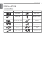 7
7
-
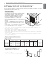 8
8
-
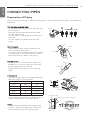 9
9
-
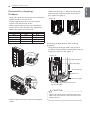 10
10
-
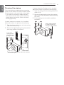 11
11
-
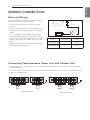 12
12
-
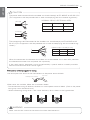 13
13
-
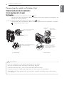 14
14
-
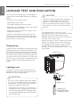 15
15
-
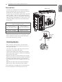 16
16
-
 17
17
-
 18
18
-
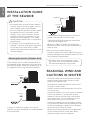 19
19
-
 20
20
-
 21
21
-
 22
22
-
 23
23
-
 24
24
-
 25
25
-
 26
26
-
 27
27
-
 28
28
-
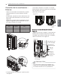 29
29
-
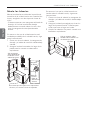 30
30
-
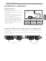 31
31
-
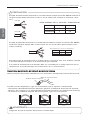 32
32
-
 33
33
-
 34
34
-
 35
35
-
 36
36
-
 37
37
-
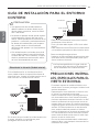 38
38
-
 39
39


LG AVNW36GM1S0.ANWTSAN Guía de instalación
- Tipo
- Guía de instalación
- Este manual también es adecuado para
en otros idiomas
Artículos relacionados
-
LG ARUV40GS2A Manual de usuario
-
LG UU24WC Guía de instalación
-
LG ABUW18GM1S1 Guía de instalación
-
-
LG A3UW36GFAB.AWGTLAR Manual de usuario
-
LG A3UW24GFAB El manual del propietario
-
LG PM15SP Manual de usuario
-
-
LG UU18W.UE4 Guía de instalación