TRUporte PV3330GGFGE072080 Manual de usuario
- Tipo
- Manual de usuario

97-PV3300
MKTD 3608
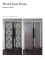
Pivot Closet Doors
Interior Doors
INSTALLATION INSTRUCTIONS

2 | | 3
Installation Instructions Installation Instructions
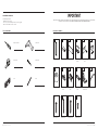
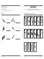
TOOLS REQUIRED PACKAGE CONTENTS
Phillips Screwdriver Cordless Drill
Tape Measure
Level Pencil
3/16" Drill Bit
IMPO RTANT
VERIFY THAT ALL PARTS ARE INCLUDED IN THE PACKAGING. IF ANY PARTS ARE MISSING, DO NOT RETURN THIS PRODUCT TO THE STORE. FOR
ANY PARTS ASSISTANCE, PLEASE CALL 1-800-493-5263 BETWEEN 8:30 AM - 4:30 PM, MONDAY TO FRIDAY
PLEASE READ CAREFULLY
General safety rules follow
• Read all instructions carefully
• Protect your eyes when handling metal parts, wear safety goggles
• Make sure the installation area is free of clutter
2x
Door Panel
2x
Bumper
10x
1-½"
Flat Head Screw
12x
1-¼"
Pan Head Screw
2x
Mount
Plate
2x
2"
Pan Head Screw
3x
⅝"
Pan Head Screw
2x
Top
Pivot
2x
Bottom
Pivot
2x
Jamb
Pivot Bracket
1x
Wrench
1x
Track
1x
Fascia
1x
Magnet
Bracket
2x
Magnet
Plate
2x
Pull

1/2 in
2 in
Step 3
On the top of the door panel, position the outside edge
of the mounting plate 1/2 in from the edge of the door.
This will also ensure the pivot is located 2 in from the
edge of the door. Use 1-1/4 in pan head screws to
secure into place.
Note: Secure the mounting plate with the locking latch
at the back of the door panel.
5/8 in
2 in
On the bottom of the door panel, position the outside
edge of the bottom pivot 5/8 in from the edge of the
door. This will also ensure the pivot is located 2 in from
the edge of the door. Use 1-1/2 in flat head screws to
secure into place.
Repeat installation of the moutning plate and bottom
pivot for the second panel.
2-1/4 in
2-1/4 in
Step 1
Insert each top pivot to both sides of the track.
Note: The securing screws should face outwards.
Measure and line up the center of the pivot to 2-1/4 in
at both ends of the track and tighten both securing
screws using a Philips Screwdriver.
Step 2
Measure 1/4 in in from the front of the opening to
correctly position the track and secure in place
using the 2-1/4 in pan head Phillips Screws.
1/4 in
2-1/4 in
2-1/4 in
Step 1
Insert each top pivot to both sides of the track.
Note: The securing screws should face outwards.
Measure and line up the center of the pivot to 2-1/4 in
at both ends of the track and tighten both securing
screws using a Philips Screwdriver.
Step 2
Measure 1/4 in in from the front of the opening to
correctly position the track and secure in place
using the 2-1/4 in pan head Phillips Screws.
1/4 in
4 | | 5
Installation Instructions Installation Instructions
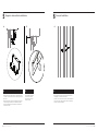
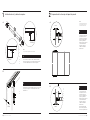
2
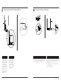
Door panel hardware preparation
On the top of the door panel,
position the outside edge of
the mounting plate ½" from
the edge of the door. This will
also ensure the pivot is
located 2" from the edge of
the door. Use 1-¼" pan head
screws to secure into place.
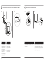
Insert each top pivot to both sides of the track. Measure and line up
the center of the pivot to 2-¼" at both ends of the track and tighten
both securing screws using a Phillips Screwdriver.
Measure ¼" from the front of the opening to correctly position the
track and secure in place using the 2-¼" pan head Phillips Screws.
On the bottom of the door
panel, position the outside
edge of the bottom pivot ⅝"
from the edge of the door.
This will also ensure the pivot
is located 2" from the edge of
the door. Use 1-½" flat head
screws to secure into place.
Repeat installation of the
mounting plate and bottom
pivot for the second panel.
A
A
B
B
AA
B
1
Top location and track installation
The securing screws should face outwards.
Secure the mounting plate with
the locking latch at the back of the
door panel.
NOTE
NOTE
B

Step 4
Position the bottom jamb pivot braclet 13/16 in
from the front of the opening. Using a Phillips
Screwdriver, insert 1-1/2 in flat head screws and
secure using all three holes.
Extend the bracket so that the hole location is 2-1/4 in
and secure in place by tightening the screw.
Repeat for the second bottom jamb pivot bracket on
the opposite side of your jamb opening.
2-1/4 in
13/16 in
3-1/2 in
11/16 in
Step 5
Position the Floor Bumper 3-1/2 in from the jamb
opening and 11/16 in from the pivot hole of the
bottom pivot jamb bracket. Use a 2 in pan head
screw to secure into place.
Repeat for the second bumper on the opposite side
of your jamb opening.
Step 6
Open the locking latch on the mounting plate and
position the door panel so that the pivot bolt can be
engaged inside the mounting plate. Close the locking
latch to secure the panel in place.
Lower the door panel so that the bottom pivot
engages the bottom jamb pivot bracket. The spring
action will suspend the door panel.
Ensure there is sufficient clearance so that no other
parts touch for clear operation. Using the adjustment
Wrench, rotate the hex bolt pivot nut to either raise or
lower the door panel.
Repeat for the second door panel.
6 | | 7
Installation Instructions Installation Instructions
43
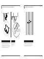
Door panel installation and adjustmentJamb pivot bracket and floor bumper installation
Position the bottom jamb
pivot bracket ⁄" from the
front of the opening. Using a
Phillips Screwdriver, insert
1-½" flat head screws and
secure using all three holes.
Extend the bracket so that the
hole location is 2-¼" and
secure in place by tightening
the screw.
Repeat for the second bottom
jamb pivot bracket on the
opposite side of your jamb
opening.
Position the Floor Bumper
3-½" from the jamb opening
and ⁄" from the pivot hole
of the bottom pivot jamb
bracket. Use a 2" pan head
screw to secure into place.
Repeat for the second bumper
on the opposite side of your
jamb opening.
A B
A B
Open the locking latch on the mounting plate and position the door
panel so that the pivot bolt can be engaged inside the mounting
plate. Close the locking latch to secure the panel in place.
Lower the door panel so that the bottom pivot engages the bottom
jamb pivot bracket. The spring action will suspend the door panel.
Ensure there is sucient clearance so that no other parts touch for
clear operation.
Using the adjustment wrench, rotate the hex bolt pivot nut to either
raise or lower the door panel.
Repeat for the second door panel.
A B
A B

Step 7
With both door panels installed, secure each magnet
plate holders to the back of the door panels, flush to
the corners using the 5/8 in pan head screws.
With both door panels closed, position the magnet
bracket in place so that the magnetic strips make
contact with the plate holders inside the opening and
secure the bracket in position using the 2 in screws into
the header.
Step 8
Peel the double-sided tape off the back of the fascia and
apply directly onto the front surface of the track.
Step 9
Measure up from the bottom of the door 36 in and
inside from the opening edge 1-1/2 in to determine
knob locations.
Pilot hole 3/16 in holes from the front of the door
panels and thread the screws in from the back.
Attach the pulls from the front tightening by hand to
complete the installation.
8 | | 9
Installation Instructions Installation Instructions
5
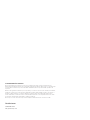
Magnetic catch and fascia installation
A AB
6
Door pull installation
With both door panels installed, secure each magnet plate holders
to the back of the door panels, flush to the corners using the ⅝" pan
head screws.
With both door panels closed, position the magnet bracket in place
so that the magnetic strips make contact with the plate holders
inside the opening and secure the bracket in position using the 2"
screws into the header.
Measure up from the bottom of the door 36" and inside from the
opening edge 1-½" to determine knob locations.
Pilot hole ⁄" holes from the front of the door panels and thread the
screws in from the back. Attach the pulls from the front tightening
by hand to complete the installation.
Peel the double-sided tape o
the back of the fascia and
apply directly onto the front
surface of the track.
A AB

Contact Us
1-800-493-5263
5 YEAR LIMITED WARRANTY
Renin Corp warranties their products against manufacturer’s defects for up to five years from the
purchase date. The warranty applies only to the original purchaser of the product from Renin Corp.
If a product is determined to be defective due to a manufacturers defect, Renin Corp will supply a
replacement product. The scope of the warranty is limited to replacing the product and does not include
labor to install, repair, deliver, or to remove the existing illuminated mirror.
This warranty is void in the event the product is damaged in transit, or if damage or failure is caused by
abuse, misuse, storage of products in an improper environment, abnormal usage, faulty installation,
failure to follow installation instructions, damage in an accident, improper maintenance, or any repair.
Renin Corp reserves the right to inspect any claim prior to issuing credit.
97-PV3300
MKTD 3608
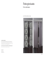
Portes pivotantes
Portes intérieures
INSTRUCTIONS D’INSTALLATION

12 | | 13
Instructions d’installation Instructions d’installation
Tournevis cruciforme Perceuse
Ruban à mesurer
Niveau Crayon
Mèche de perceuse de ⁄po
2x
Door Panel
2x
Bumper
10x
1-½"
Flat Head Screw
12x
1-¼"
Pan Head Screw
2x
Mount
Plate
2x
2"
Pan Head Screw
3x
⅝"
Pan Head Screw
2x
Top
Pivot
2x
Bottom
Pivot
2x
Jamb
Pivot Bracket
1x
Wrench
1x
Track
1x
Fascia
1x
Magnet
Bracket
2x
Magnet
Plate
2x
Pull
VEUILLEZ LIRE ATTENTIVEMENT
OUTILS REQUIS CONTENU DE L’EMBALLAGE, CE QUE NOUS FOURNISSONS
Voici les consignes de sécurité générale
IMPO RTANT!
VÉRIFIEZ QUE TOUTES LES PIÈCES SONT COMPRISES DANS L’EMBALLAGE.
SI DES PIÈCES MANQUENT, VEUILLEZ NE PAS RETOURNER CE PRODUIT AU MAGASIN. POUR TOUTE ASSISTANCE RELATIVE AUX PIÈCES,
VEUILLEZ COMPOSER LE 1-800-493-5263 ENTRE 8H30 ET 16H30, DU LUNDI AU VENDREDI.
• Lisez attentivement toutes les instructions
• Protégez vos yeux en portant des lunettes de sécurité lorsque vous manipulez des pièces en métal
• Assurez-vous que la surface d’installation n’est pas obstruée

1/2 in
2 in
Step 3
On the top of the door panel, position the outside edge
of the mounting plate 1/2 in from the edge of the door.
This will also ensure the pivot is located 2 in from the
edge of the door. Use 1-1/4 in pan head screws to
secure into place.
Note: Secure the mounting plate with the locking latch
at the back of the door panel.
5/8 in
2 in
On the bottom of the door panel, position the outside
edge of the bottom pivot 5/8 in from the edge of the
door. This will also ensure the pivot is located 2 in from
the edge of the door. Use 1-1/2 in flat head screws to
secure into place.
Repeat installation of the moutning plate and bottom
pivot for the second panel.
2-1/4 in
2-1/4 in
Step 1
Insert each top pivot to both sides of the track.
Note: The securing screws should face outwards.
Measure and line up the center of the pivot to 2-1/4 in
at both ends of the track and tighten both securing
screws using a Philips Screwdriver.
Step 2
Measure 1/4 in in from the front of the opening to
correctly position the track and secure in place
using the 2-1/4 in pan head Phillips Screws.
1/4 in
2-1/4 in
2-1/4 in
Step 1
Insert each top pivot to both sides of the track.
Note: The securing screws should face outwards.
Measure and line up the center of the pivot to 2-1/4 in
at both ends of the track and tighten both securing
screws using a Philips Screwdriver.
Step 2
Measure 1/4 in in from the front of the opening to
correctly position the track and secure in place
using the 2-1/4 in pan head Phillips Screws.
1/4 in
14 | | 15
Instructions d’installation Instructions d’installation
2
Door panel hardware preparation
On the top of the door panel,
position the outside edge of
the mounting plate ½" from
the edge of the door. This will
also ensure the pivot is
located 2" from the edge of
the door. Use 1-¼" pan head
screws to secure into place.
Insert each top pivot to both sides of the track. Measure and line up
the center of the pivot to 2-¼" at both ends of the track and tighten
both securing screws using a Phillips Screwdriver.
Measure ¼" from the front of the opening to correctly position the
track and secure in place using the 2-¼" pan head Phillips Screws.
On the bottom of the door
panel, position the outside
edge of the bottom pivot ⅝"
from the edge of the door.
This will also ensure the pivot
is located 2" from the edge of
the door. Use 1-½" flat head
screws to secure into place.
Repeat installation of the
mounting plate and bottom
pivot for the second panel.
A
A
B
B
AA
B
1
Top location and track installation
The securing screws should face outwards.
Secure the mounting plate with
the locking latch at the back of the
door panel.
NOTE
NOTE
B

Step 4
Position the bottom jamb pivot braclet 13/16 in
from the front of the opening. Using a Phillips
Screwdriver, insert 1-1/2 in flat head screws and
secure using all three holes.
Extend the bracket so that the hole location is 2-1/4 in
and secure in place by tightening the screw.
Repeat for the second bottom jamb pivot bracket on
the opposite side of your jamb opening.
2-1/4 in
13/16 in
3-1/2 in
11/16 in
Step 5
Position the Floor Bumper 3-1/2 in from the jamb
opening and 11/16 in from the pivot hole of the
bottom pivot jamb bracket. Use a 2 in pan head
screw to secure into place.
Repeat for the second bumper on the opposite side
of your jamb opening.
Step 4
Position the bottom jamb pivot braclet 13/16 in
from the front of the opening. Using a Phillips
Screwdriver, insert 1-1/2 in flat head screws and
secure using all three holes.
Extend the bracket so that the hole location is 2-1/4 in
and secure in place by tightening the screw.
Repeat for the second bottom jamb pivot bracket on
the opposite side of your jamb opening.
2-1/4 in
13/16 in
3-1/2 in
11/16 in
Step 5
Position the Floor Bumper 3-1/2 in from the jamb
opening and 11/16 in from the pivot hole of the
bottom pivot jamb bracket. Use a 2 in pan head
screw to secure into place.
Repeat for the second bumper on the opposite side
of your jamb opening.
Step 6
Open the locking latch on the mounting plate and
position the door panel so that the pivot bolt can be
engaged inside the mounting plate. Close the locking
latch to secure the panel in place.
Lower the door panel so that the bottom pivot
engages the bottom jamb pivot bracket. The spring
action will suspend the door panel.
Ensure there is sufficient clearance so that no other
parts touch for clear operation. Using the adjustment
Wrench, rotate the hex bolt pivot nut to either raise or
lower the door panel.
Repeat for the second door panel.
Step 6
Open the locking latch on the mounting plate and
position the door panel so that the pivot bolt can be
engaged inside the mounting plate. Close the locking
latch to secure the panel in place.
Lower the door panel so that the bottom pivot
engages the bottom jamb pivot bracket. The spring
action will suspend the door panel.
Ensure there is sufficient clearance so that no other
parts touch for clear operation. Using the adjustment
Wrench, rotate the hex bolt pivot nut to either raise or
lower the door panel.
Repeat for the second door panel.
16 | | 17
Instructions d’installation Instructions d’installation
43
Door panel installation and adjustmentJamb pivot bracket and floor bumper installation
Position the bottom jamb
pivot bracket ⁄" from the
front of the opening. Using a
Phillips Screwdriver, insert
1-½" flat head screws and
secure using all three holes.
Extend the bracket so that the
hole location is 2-¼" and
secure in place by tightening
the screw.
Repeat for the second bottom
jamb pivot bracket on the
opposite side of your jamb
opening.
Position the Floor Bumper
3-½" from the jamb opening
and ⁄" from the pivot hole
of the bottom pivot jamb
bracket. Use a 2" pan head
screw to secure into place.
Repeat for the second bumper
on the opposite side of your
jamb opening.
A B
A B
Open the locking latch on the mounting plate and position the door
panel so that the pivot bolt can be engaged inside the mounting
plate. Close the locking latch to secure the panel in place.
Lower the door panel so that the bottom pivot engages the bottom
jamb pivot bracket. The spring action will suspend the door panel.
Ensure there is sucient clearance so that no other parts touch for
clear operation.
Using the adjustment wrench, rotate the hex bolt pivot nut to either
raise or lower the door panel.
Repeat for the second door panel.
A B
A B

Step 7
With both door panels installed, secure each magnet
plate holders to the back of the door panels, flush to
the corners using the 5/8 in pan head screws.
With both door panels closed, position the magnet
bracket in place so that the magnetic strips make
contact with the plate holders inside the opening and
secure the bracket in position using the 2 in screws into
the header.
Step 8
Peel the double-sided tape off the back of the fascia and
apply directly onto the front surface of the track.
Step 7
With both door panels installed, secure each magnet
plate holders to the back of the door panels, flush to
the corners using the 5/8 in pan head screws.
With both door panels closed, position the magnet
bracket in place so that the magnetic strips make
contact with the plate holders inside the opening and
secure the bracket in position using the 2 in screws into
the header.
Step 8
Peel the double-sided tape off the back of the fascia and
apply directly onto the front surface of the track.
Step 7
With both door panels installed, secure each magnet
plate holders to the back of the door panels, flush to
the corners using the 5/8 in pan head screws.
With both door panels closed, position the magnet
bracket in place so that the magnetic strips make
contact with the plate holders inside the opening and
secure the bracket in position using the 2 in screws into
the header.
Step 8
Peel the double-sided tape off the back of the fascia and
apply directly onto the front surface of the track.
Step 7
With both door panels installed, secure each magnet
plate holders to the back of the door panels, flush to
the corners using the 5/8 in pan head screws.
With both door panels closed, position the magnet
bracket in place so that the magnetic strips make
contact with the plate holders inside the opening and
secure the bracket in position using the 2 in screws into
the header.
Step 8
Peel the double-sided tape off the back of the fascia and
apply directly onto the front surface of the track.
Step 9
Measure up from the bottom of the door 36 in and
inside from the opening edge 1-1/2 in to determine
knob locations.
Pilot hole 3/16 in holes from the front of the door
panels and thread the screws in from the back.
Attach the pulls from the front tightening by hand to
complete the installation.
18 | | 19
Instructions d’installation Instructions d’installation
5
Magnetic catch and fascia installation
A AB
6
Door pull installation
With both door panels installed, secure each magnet plate holders
to the back of the door panels, flush to the corners using the ⅝" pan
head screws.
With both door panels closed, position the magnet bracket in place
so that the magnetic strips make contact with the plate holders
inside the opening and secure the bracket in position using the 2"
screws into the header.
Measure up from the bottom of the door 36" and inside from the
opening edge 1-½" to determine knob locations.
Pilot hole ⁄" holes from the front of the door panels and thread the
screws in from the back. Attach the pulls from the front tightening
by hand to complete the installation.
Peel the double-sided tape o
the back of the fascia and
apply directly onto the front
surface of the track.
A AB

1-800-493-5263
5 YEAR GARANTIE LIMITÉE
Renin Corp garantit ses produits contre les défauts de fabrication pendant cinq ans à compter de la date
d’achat. Cette garantie ne vise que l’acheteur original du produit de Renin Corp.
Si un produit est jugé défectueux en raison d’un défaut de fabrication, Renin Corp fournira un produit de
remplacement. L’étendue de la garantie est limitée au remplacement du produit et ne couvre pas la main
d’œuvre pour l’installation, la réparation, la livraison ou le retrait du miroir illuminé existant.
Cette garantie est nulle si le produit est endommagé pendant le transport ou si le dommage ou la
défaillance résulte d’un usage abusif, d’un mauvais usage, de l’entreposage des produits dans un
environnement inadéquat, d’un usage anormal, d’une mauvaise installation, d’un manque à suivre les
instructions d’installation, d’un accident, d’un mauvais entretien ou de toute réparation. Renin Corp se
réserve le droit d’examiner toute réclamation avant d’émettre un crédit.
97-PV3300
MKTD 3608
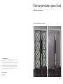
Puertas pivotantes para clóset
Puertas interiores
INSTRUCCIONES DE INSTALACIÓN
Pour nous joindre

22 | | 23
Instrucciones de instalación Instrucciones de instalación
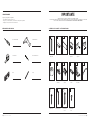
HERRAMIENTAS NECESARIAS CONTENIDO DEL PAQUETE - QUÉ SUMINISTRAMOS
Destornillador Phillips Taladro inalámbrico
Cinta de medir
Nivel Lápiz
Broca de taladro de ⁄”
I MPORTANTE
VERIFICAR QUE TODAS LAS PIEZAS Y PARTES SE INCLUYEN EN EL PAQUETE.
SI ALGUNA PIEZA O PARTE ESTÁ EN FALTA, NO DEVOLVER ESTE PRODUCTO A LA TIENDA. PARA ASISTENCIA CON RESPECTO A CUALQUIER
PIEZA O PARTE, LLAMAR POR FAVOR AL 1-800-493-5263 ENTRE 8:30 AM Y 4:30 PM DE LUNES A VIERNES
LEER ATENTAMENTE
Sigue las reglas generales de seguridad
• Leer cuidadosamente todas las instrucciones.
• Proteger los ojos al manipular piezas y partes metálicas, usando gafas de seguridad.
• Asegurar que no haya desorden en el área de instalación.
2x
Panel
de la puerta
2x
Protector
10x
Tornillo de cabeza
plana de 1-½"
12x
Tornillo de cabeza
plana biselada
de 1-¼"
2x
Placa
de montaje
2x
Tornillo de cabeza
plana biselada de 2"
3x
Tornillo de cabeza
plana biselada
de ⅝"
2x
Pivote
superior
2x
Pivote
inferior
2x
Soporte pivotante
de la jamba
1x
Llave
1x
Riel
1x
Imposta
1x
Soporte
magnético
2x
Placa
magnética
2x
Tirador

1/2 in
2 in
Step 3
On the top of the door panel, position the outside edge
of the mounting plate 1/2 in from the edge of the door.
This will also ensure the pivot is located 2 in from the
edge of the door. Use 1-1/4 in pan head screws to
secure into place.
Note: Secure the mounting plate with the locking latch
at the back of the door panel.
5/8 in
2 in
On the bottom of the door panel, position the outside
edge of the bottom pivot 5/8 in from the edge of the
door. This will also ensure the pivot is located 2 in from
the edge of the door. Use 1-1/2 in flat head screws to
secure into place.
Repeat installation of the moutning plate and bottom
pivot for the second panel.
2-1/4 in
2-1/4 in
Step 1
Insert each top pivot to both sides of the track.
Note: The securing screws should face outwards.
Measure and line up the center of the pivot to 2-1/4 in
at both ends of the track and tighten both securing
screws using a Philips Screwdriver.
Step 2
Measure 1/4 in in from the front of the opening to
correctly position the track and secure in place
using the 2-1/4 in pan head Phillips Screws.
1/4 in
2-1/4 in
2-1/4 in
Step 1
Insert each top pivot to both sides of the track.
Note: The securing screws should face outwards.
Measure and line up the center of the pivot to 2-1/4 in
at both ends of the track and tighten both securing
screws using a Philips Screwdriver.
Step 2
Measure 1/4 in in from the front of the opening to
correctly position the track and secure in place
using the 2-1/4 in pan head Phillips Screws.
1/4 in
24 | | 25
Instrucciones de instalación Instrucciones de instalación
2
Preparación de los herrajes del panel de puerta
A Sobre la parte superior del
panel de puerta, colocar el
borde externo de la placa de
montaje a ½" del borde de la
puerta. Esto garantizará
también que el pivote quede a
2" del borde de la puerta.
Asegurar en el lugar con
tornillos de cabeza plana
biselada de 1-¼".
A Insertar cada pivote superior en ambos lados del riel. Medir y
alinear el centro del pivote a 2-¼" de ambos lados del riel y apretar
con el destornillador Phillips ambos tornillos para asegurar.
Medir ¼" desde el frente de la abertura hasta la posición correcta del
riel y asegurar en el lugar con tornillos Phillips de cabeza plana
biselada de 2-¼".
Sobre la parte inferior del
panel de puerta, colocar el
borde externo del pivote
inferior a ⅝" del borde de la
puerta. Esto garantizará
también que el pivote quede a
2" del borde de la puerta.
Asegurar en el lugar con
tornillos de cabeza plana
biselada de 1-½".
Repetir la instalación de la
placa de montaje y del pivote
inferior para el segundo panel.
A
A
B
B
AA
B
1
Instalación de riel y ubicación superior
Los tornillos para asegurar deben mirar hacia afuera.
Asegurar la placa de montaje con
el cierre de bloqueo en la parte
posterior del panel de puerta.
NOTA
NOTA
B

Step 4
Position the bottom jamb pivot braclet 13/16 in
from the front of the opening. Using a Phillips
Screwdriver, insert 1-1/2 in flat head screws and
secure using all three holes.
Extend the bracket so that the hole location is 2-1/4 in
and secure in place by tightening the screw.
Repeat for the second bottom jamb pivot bracket on
the opposite side of your jamb opening.
2-1/4 in
13/16 in
3-1/2 in
11/16 in
Step 5
Position the Floor Bumper 3-1/2 in from the jamb
opening and 11/16 in from the pivot hole of the
bottom pivot jamb bracket. Use a 2 in pan head
screw to secure into place.
Repeat for the second bumper on the opposite side
of your jamb opening.
Step 6
Open the locking latch on the mounting plate and
position the door panel so that the pivot bolt can be
engaged inside the mounting plate. Close the locking
latch to secure the panel in place.
Lower the door panel so that the bottom pivot
engages the bottom jamb pivot bracket. The spring
action will suspend the door panel.
Ensure there is sufficient clearance so that no other
parts touch for clear operation. Using the adjustment
Wrench, rotate the hex bolt pivot nut to either raise or
lower the door panel.
Repeat for the second door panel.
26 | | 27
Instrucciones de instalación Instrucciones de instalación
43
Instalación y ajuste del panel de puertaInstalación del protector del piso y soporte pivotante de la jamba
Colocar el soporte pivotante
de la jamba inferior a ⁄" del
frente de la abertura. Con un
destornillador Phillips, insertar
tornillos de cabeza plana de
1-½" y asegurar usando los
tres orificios. Extender el
soporte de manera que la
ubicación del orificio sea 2-¼"
y asegurar en el lugar
apretando el tornillo.
Repetir para el segundo
soporte pivotante de la jamba
inferior en el lado opuesto de
la abertura de la jamba.
Colocar el protector del piso a
3-½" de la abertura de la
jamba y a ⁄" del orificio del
pivote del soporte de jamba
pivotante inferior. Asegurar en
el lugar con un tornillo de
cabeza plana biselada de 2".
Repetir para el segundo
protector en el lado opuesto
de la abertura de la jamba.
A B
A B
Abrir el cierre de bloqueo en la placa de montaje y colocar el panel
de puerta de manera que el perno pivotante pueda acoplarse dentro
de aquella placa. Poner de nuevo el cierre de bloqueo para asegurar
el panel en su lugar.
Bajar el panel de puerta de manera que el pivote inferior se acople
con el soporte pivotante de la jamba inferior. La acción de resorte
dejará suspendido el panel de la puerta. Garantizar que haya
suficiente espacio libre para que las partes no se toquen y la
operación pueda efectuarse sin obstrucción. Usando la llave de
ajuste, girar la tuerca pivotante del perno hexagonal para subir o
bajar el panel de puerta.
Repetir para el segundo panel de puerta.
A B
A B

Step 7
With both door panels installed, secure each magnet
plate holders to the back of the door panels, flush to
the corners using the 5/8 in pan head screws.
With both door panels closed, position the magnet
bracket in place so that the magnetic strips make
contact with the plate holders inside the opening and
secure the bracket in position using the 2 in screws into
the header.
Step 8
Peel the double-sided tape off the back of the fascia and
apply directly onto the front surface of the track.
Step 9
Measure up from the bottom of the door 36 in and
inside from the opening edge 1-1/2 in to determine
knob locations.
Pilot hole 3/16 in holes from the front of the door
panels and thread the screws in from the back.
Attach the pulls from the front tightening by hand to
complete the installation.
28 | | 29
Instrucciones de instalación Instrucciones de instalación
5
Instalación de imposta y enganche magnético
A AB
6
Instalación del tirador de puerta
Con ambos paneles de puerta instalados, asegurar cada sujetador
de placa magnético a la parte posterior de los paneles, a ras con las
esquinas, usando los tornillos de cabeza plana biselada de ⅝".
Con ambos paneles de puerta cerrados, colocar el suporte magnéti-
co en su lugar para que las franjas magnéticas hagan contacto con
los sujetadores de placa dentro de la abertura y asegurar el soporte
en su lugar insertando los tornillos de 2" en el dintel.
Medir 36" desde la parte inferior de la puerta y 1" hacia dentro desde
el borde de abertura para determinar las ubicaciones de perilla.
Abrir orificios de ⁄" desde el frente de los paneles de la puerta y
atornillar desde la parte posterior. Fijar los tiradores desde el frente
apretando con la mano hasta completar la instalación.
Despegar la cinta adhesiva de
doble faz de la parte posterior
de la imposta y aplicar
directamente a la superficie
frontal del riel.
A AB

Contáctanos
1-800-493-5263
5 YEAR GARANTÍA LIMITADA
Renin Corp garantiza sus productos por cinco años, a partir de la fecha de compra, contra defectos de
fabricación. Esta garantía se aplica solo al comprador original del producto de Renin Corp. Si se determina que
cierto producto es defectuoso por causa de falla de manufactura, Renin Corp suministrará el producto de
reposición.
El alcance de la garantía se limita a reponer el producto y no cubre los costos de mano de obra por instalación,
reparación y entrega, ni por retiro del espejo iluminado precedente. Esta garantía se anula en caso de que el
producto se dañe en tránsito, o si el daño o falla trae su causa de abuso, uso inapropiado, almacenaje en
entorno inadecuado, consumo fuera de lo normal, instalación deficiente o sin cumplir las instrucciones, daño
por accidente, mantenimiento inapropiado o cualquier reparación.
Renin Corp se reserva el derecho a inspeccionar cualquier reclamación antes de conceder el crédito.
-
 1
1
-
 2
2
-
 3
3
-
 4
4
-
 5
5
-
 6
6
-
 7
7
-
 8
8
-
 9
9
-
 10
10
-
 11
11
-
 12
12
-
 13
13
-
 14
14
-
 15
15
-
 16
16


TRUporte PV3330GGFGE072080 Manual de usuario
- Tipo
- Manual de usuario
en otros idiomas
Artículos relacionados


Otros documentos
-
Delta 170253 Guía de instalación
-
Delta SDKB005-PC-B1 Guía de instalación
-
ReliaBilt 449304 Guía de instalación
-
Kohler K-705810-L-ABV Guía de instalación
-
MAAX 105416-900-084-000 Madono Pivot Shower Door 28 ½-30 ½ x 67 in. 6 mm Guía de instalación
-
-
-
-
-