Fortis 8810900TB Guía de instalación
- Categoría
- Artículos sanitarios
- Tipo
- Guía de instalación

8 8 1 0 9 0 0 C A F F è
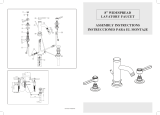
5 - H o l e R o m a n t u b k i t • G r u p o b o r d e b a ñ e r a
VPC2202101434
For information such as installation or
care and warranty for this product, please
contact your local Fortis distributor.
www.fortisfaucet.com
Para informacion sobre la instalación, o
cuidar el producto y garantia, por favor
llama a su distribuidor local de Fortis.
www.fortisfaucet.com
02-22-2010
Copyright
©
2009, Fortis
8810900
English Español
Fortis 877 55 FORTIS - (36784) Da Vinci
Lake Forest, CA 92610
www.fortisfaucet.com
support@fortisfaucet.com
for technical support call
1-877-280-5940
English Español
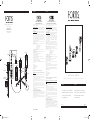
LIMITED LIFETIME WARRANTY
FOR RESIDENTIAL PRODUCTS
FORTIS provides the following warranties for its products to the original
purchaser in a residential application.
MECHANICAL WARRANTY: FORTIS provides a Limited Lifetime Warranty
to all mechanical parts to be free from all manufacturing defects in materials
and workmanship under normal use for as long as the original purchaser
owns their home.
FINISH WARRANTY: FORTIS provides a Limited Lifetime Warranty on all
Fortis products to the original purchaser against manufacturing defects in
materials and workmanship.
In the event of any defect in the product breaches the foregoing warranties,
FORTIS, at its option, will replace any part or finish that proves to be
defective in material and/or workmanship, under normal installation, use
and service. Repair or replacement of the product is the exclusive remedy.
For any remedy under this warranty, FORTIS, is to be notified describing the
problem. In order to notify FORTIS and receive assistance or service under
this warranty, the original purchaser may:
1. Contact by Phone: For a consumer service representative, call 1-877-
280-5940
2. Contact by Mail: Write consumer service department to the below
address: FORTIS, Inc.,
Customer Service Department
1571 North Main Road
Newfield, NJ 08344
(877) 280-5940
3. Contact by Email: Email Fortis customer service: customerservice@
fortisfaucet.com
4. Contact your Distributor: Notify the location or distributor from which the
product was purchased.
Upon contacting FORTIS, you will need to provide:
a. FORTIS product model number
b. A description of the problem
c. Your contact information (Name, Address, Phone Number)
d. Approximate Date of Purchase
In addition to the information above, to obtain a warranty repair or
replacement, you will need to provide:
1. The faulty part or product (carefully packed)
2. Proof-of-purchase (original sales receipt) from the original consumer
purchaser
FORTIS, Inc.,
Customer Service Department
1571 North Main Road
Newfield, NJ 08344
(877) 280-5940
Please allow 7 to 14 business days warranty processing.
EXCLUSIONS: This warranty does NOT cover and FORTIS will NOT
pay for:
1. Conditions, malfunctions or damage not resulting from defects in material
or workmanship
2. Conditions, malfunctions or damage resulting from any of the following:
a. Normal wear and tear, improper installation, improper maintenance,
misuse, abuse, negligence, accident or alteration
b. The use of abrasive or caustic cleaning agents or “no-rinse” cleaning
products, or the use of the product in any manner contrary to the product
instructions
c. Conditions in the home such as excessive water pressure or corrosion
3. Labor and other expenses related to disconnection, deinstallation, or
return of the product for warranty service (including but not limited to proper
packaging and shipping costs) or for installation or reinstallation of the
product
4. Accessories, connected to materials and products, or related products not
manufactured by FORTIS.
5. Any FORTIS product sold for display purposes.
WARRANTY FOR COMMERCIAL APPLICATIONS:
If the FORTIS product is installed in a commercial application, the above
mechanical warranty shall be limited for a period of (10) years and the
above finish warranty shall be limited for a period of (5) years from the date
of the purchase of the product.
Repair or replacement parts are warranted only for the period remaining
under the initial warranty. The same exclusions apply as above residential
application policy.
GARANTÍA LIMITADA DE POR VIDA
PARA PRODUCTOS DE USO RESIDENCIAL
FORTIS ofrece al comprador original las siguientes garantías para sus
productos utilizados para instalaciones residenciales.
GARANTÍA PARTES MECÁNICAS: FORTIS ofrece para todos los
componentes mecánicos una Garantía Limitada de por vida que cubre los
defectos de fabricación en los materiales y elaboración, en condiciones de
uso normales, hasta que el comprador original sea propietario del inmueble
donde se instala el producto.
GARANTÍA ACABADOS: FORTIS ofrece al comprador original para todos
los productos FORTIS una Garantía Limitada de por vida que cubre los
defectos de fabricación en los materiales y la elaboración.
En caso de que un producto no fuera conforme a los parámetros de las
mencionadas garantías debido a algún defecto, FORTIS, a su exclusiva
discreción, sustituirá el componente o el acabado defectuoso en el
material y/o la elaboración en normales condiciones de instalación,
uso y mantenimiento. La única solución admitida será la reparación o la
sustitución del producto.
Para hacer valer cualquier tipo de cobertura prevista por la garantía el
usuario deberá enviar la solicitud a FORTIS junto con una descripción
completa del problema. Para notificar a FORTIS y recibir asistencia o un
servicio en conformidad a la presente garantía, el comprador original
podrá:
1. Llamar por teléfono: para ponerse en contacto con un representante del
servicio de atención al cliente al número 1-877-280-5940
2. Por correo: Escribir a la oficina del servicio de atención al cliente a la
siguiente dirección: FORTIS, Inc.,
Customer Service Department
1571 North Main Road
Newfield, NJ 08344
(877) 280-5940
3. Por email: Email del servicio de atención al cliente FORTIS:
customerservice@fortisfaucet.com
4. Contactar a nuestro distribuidor: Comunicar el lugar o el distribuidor
donde ha sido comprado el producto.
Después de haberse puesto en contacto con FORTIS, deberán indicar:
a. El número del modelo del producto FORTIS
b. Una descripción del problema
c. Las informaciones para contactarles (nombre, dirección, número de
teléfono)
d. Fecha de compra aproximada
Para poder recibir asistencia para la reparación o sustitución en garantía,
además de las informaciones anteriormente mencionadas, deberán enviar
lo siguiente:
1. El componente o producto defectuoso (cuidadosamente embalado)
2. El comprobante de compra (recibo de compra original) que el comprador
original del producto posee.
FORTIS, Inc.,
Customer Service Department
1571 North Main Road
Newfield, NJ 08344
(877) 280-5940
Para la elaboración de la solicitud de aplicación de la garantía serán
necesarios de 7 a 14 días laborales.
EXCEPCIONES: La presente garantía NO cubre y FORTIS NO pagará
por:
1. Las condiciones, los malfuncionamientos o los daños que no sean debidos
a defectos de material o elaboración
2. Las condiciones, los malfuncionamientos o los daños debidos a uno de los
siguientes casos:
a. Normal desgaste, instalación incorrecta, mantenimiento incorrecto, uso
impropio, abuso, negligencia, accidente o alteración
b. Uso de agentes abrasivos o productos de limpieza corrosivos o que no
necesitan enjuague, o uso impropio del producto contrario a las indicaciones
c. Condiciones del inmueble producidas por excesiva presión del agua o
corrosión
3. Mano de obra y otros gastos relativos a la desconexión, desmontaje
o restitución del producto por servicios de garantía (incluso el embalaje
adecuado y los costos de expedición) o por la instalación o el desmontaje
del producto.
4. Accesorios, relacionados con los materiales y productos, o relativos a
productos no fabricados por FORTIS.
5. Los productos FORTIS vendidos exclusivamente con fines de exposición.
GARANTÍA PARA USOS COMERCIALES:
En caso de que el producto FORTIS sea instalado en una unidad comercial,
la garantía para las partes mecánicas anteriormente indicada será limitada a
un período de (10) años y la garantía para los acabados será limitada a un
período de (5) años desde la fecha de compra del producto.
Las reparaciones y las piezas de repuesto están cubiertas por la garantía
sólo por el período restante de la garantía original. La misma excepción es
válida, como se indica anteriormente, para las normas aplicables al uso en
unidades residenciales.
27-910/2
88-429N
88-9013/4
27-680CC
84CC957
27-9053/4D2
27-9053/4S2
27-910/2
87-155VA
49-5813/4D
49-5813/4S
88-901/425
OR44,12X2,62
50-446SDCC
53-587FI
JUCC950G1/2
53AE950FF6
JUCC950G3/4
AC27CC109BISTUF
Istruz. art. 8810900.indd 1-3 28/04/10 10:42

EspañolEnglish
INSTALLATION INSTRUCTIONS INSTRUCCIONES DE INSTALACIÓN
En caso de presiones de funcionamiento superiores a
5 bares (~75 PSI), se aconseja el uso de un reductor
de presión. Antes de efectuar el montaje, se aconseja
purgar las tuberías del agua caliente y fría para
evitar que suciedad y pequeñas impurezas afecten el
funcionamiento del grifo.
FIG. 01 INSTALACIÓN TUBOS CON RACORES
Preparar el tubo con racores (1.I) dotado de contratuerca
(1.H), brida perfilada (1.G) y junta (1.F). Posicionar el
o-ring de base (1E) debajo del capuchón (1.D), atornillar
completamente este último, regular su posición respecto
a la pared y fijar mediante la contratuerca (1.H).
Introducir la maneta (1.C) en la varilla del cartucho,
fijarla con el tornillo (1.B) y completar montando la
placa (1.A).
FIG. 01 INSTALACIÓN BOCA DE EROGACIÓN
Posicionar la arandela de base (1.Q), y la junta (1.P), en
el vástago roscado (1.N) del cuerpo del grifo. Introducir
en el orificio del sanitario el grifo, comprobando la
correcta posición de la junta (1.P). Introducir en el
vástago roscado (1.N) la brida (1.O), la junta (1.M),
luego fijar el grifo con la contratuerca (1.L).
FIG. 02 INSTALLAZIONDE DESVIADOR
Introducir desde abajo en el orificio del sanitario el
desviador (2.I) dotado de contratuerca (2.H), brida
perfilada (2.G) y junta (2.F). Atornillar el capuchón (2.D)
introduciendo entre éste y la cerámica la junta (2.E),
luego fijar todo actuando sobre la contratuerca (2.H).
Introducir la maneta (2.C) y fijar con el tornillo (2.B),
en fin aplicar la placa (2.A). Introducir en el orificio del
sanitario el soporte de la ducha teléfono (2.O), luego
introducir el vástago roscado en la junta (2.P) y la brida
(2.Q) y apretar con la contratuerca (2.R). Atornillar el
flexible (2.N) a la ducha teléfono (2.L) introduciendo la
junta (2.M); luego introducirlo en el orificio del soporte
de la ducha teléfono (2.O), posicionando en el mismo
la ducha teléfono (2.L).
FIG. 03 CONEXIÓN FLEXIBLES
Atornillar el flexible (3.D) desde el lado G1/2” a la
salida inferior del desviador (3.L) interponiendo la junta
(3.O); atornillar el mismo desde el lado con la tuerca de
compresión de G3/4” al vástago roscado (3.F) de la
boca de erogación introduciendo la junta (3.E).
Atornillar el flexible (3.C) desde el lado G3/4” al
tubo con racores izquierdo (3.A) introduciendo la junta
(3.B); luego atornillarlo desde el lado con la tuerca de
In case of pressures over 5 BAR (~75 PSI), we
recommend to use a pressure reducer.
Before proceeding with the assembly, purge the hot and
cold water pipes so as to avoid the accumulation of dirt
and impurities that could affect the function of the faucet.
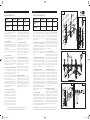
FIG. 01 VALVE INSTALLATION
Prepare the valve (1.G) as shown with the counter-nut
(1.H), the shaped flange (1.G) and the gasket (1.F). Fit
the base o-ring (1.E) under the protection cover (1.D),
tighten the protection cover all the way in and lock it with
the counter-nut (1.H).
Install the handle (1.C) on the screw down bar, lock
it with the screw (1.B) and complete by fitting the cap
(1.A),
FIG. 01 SPOUT INSTALLATION
Position the base washer (1.Q) and the gasket (1.P) on
the threaded stem (1.N) of the faucet body.
Insert the faucet into the hole of the sanitary element
carefully positioning the gasket (1.P). Install the gasket
(1.O) and the flange (1.M) on the threaded stem (1.N)
and fasten the faucet with the counter-nut (1.L).
FIG. 02 DIVERTER AND HAND SHOWER INSTALLATION
From the bottom, insert the diverter (2.I) with the counter-
nut (2.H), the shaped flange (2.G) and the gasket
(2.F) in the hole of the ceramic surface. Screw on the
protection cover (2.D) placing the gasket (2.E) between
the cover and the surface, then fasten the assembly with
the counter-nut (2.H). Install the handle (2.C) and lock
with the screw (2.B). Fit the cap (2.A).
Insert the shower support (2.O) into the ceramic surface
hole, then slide the gasket (2.P) and the flange (2.Q) on
the threaded stem and lock with the counter-nut (2.R).
Screw the flex pipe (2.N) on the hand shower (2.L)
inserting the gasket (2.M); install the assembly in the hole
of the shower support (2.S).
FIG. 03 SUPPLY FLEX HOSE CONNECTION
Connect the G1/2” end of the flex hose (3.D) to the
lower outlet of the diverter (3.L), placing the gasket
(3.O) in between; connect the G3/4” end to the
threaded stem (3.F) of the spout placing the gasket (3.E)
in between. Connect the G3/4” end of the flex hose
(3.C) to the left valve (3.A) placing the gasket (3.B) in
between; connect the G1/2” end to the left inlet of
the diverter (3.L) placing the gasket (3.M) in between.
Connect the G3/4” end of the flex hose (3.G) to the
right valve (3.I) placing the gasket (3.H) in between;
Based on its policy of steady development Fortis reserves the right to change the characteristics
of the products without notice and therefore the images and data contained in this catalogue may vary.
Por su política de continuo desarrollo, Fortis se reserva el derecho de modificar las características de los productos sin ningún aviso
previo; por tanto, las imágenes y los datos contenidos en el presente catálogo deben considerarse a título indicativo.
compresión de G1/2” en la entrada izquierda del
desviador (3.L) introduciendo la junta (3.M). Atornillar
el flexible (3.G) desde el lado G3/4” al tubo con
racores derecho (3.I) introduciendo la junta (3.H); luego
atornillarlo desde el lado con la tuerca de compresión
de G1/2” en la entrada derecha del desviador (3.L)
introduciendo la junta (3.N). Montar el racor (3.R) en
la salida central del desviador (3.L), introduciendo
la junta (3.P) y prestando atención a que la válvula
antirretroceso (3.Q) esté en la posición correcta. Luego
atornillar el flexible de la ducha teléfono (3.T) al racor
(3.R) colocando la junta (3.S).
FIG. 04 SUSTITUCIÓN CARTUCHO
En caso de que fuera necesario sustituir el cartucho
(4.E) primero es necesario aflojar la contratuerca (4.G);
desmontar la placa (4.A), destornillar el tornillo (4.B) y
retirar la maneta (4.C). Destornillar el capuchón (4.D) y
desmontar el cartucho (4.E) con una llave adecuada,
sustituirlo, si es necesario, y asegurarse de que las
superficies de estanqueidad de las juntas estén limpias.
Montar nuevamente efectuando las operaciones
inversas, prestando atención a posicionar correctamente
el o-ring (4.F) debajo del capuchón (4.D).
FIG. 05 MOVIMIENTO DE LAS MANETAS
Actuando sobre las manetas (5.A) y (5.B) se puede
regular el flujo y la temperatura del agua; moviendo
la maneta (5.B) se regula el caudal del agua fría, en
cambio moviendo la (5.A) se regula el agua caliente.
Mientras más se alejan de la posición de cierre, mayor
es el caudal. Abriendo las manetas del grupo borde
bañera el flujo el flujo se desviará hacia la boca de
erogación. Girando la maneta (5.C) de 180° en sentido
horario, el flujo será desviado a la ducha teléfono. Para
volver a la condición inicial es necesario girar la maneta
(5.C) en sentido antihorario.
MANTENIMIENTO DE LAS SUPERFICIES
Durante la limpieza la superficie del grifo debe estar fría
(el calor acelera el desgaste de la superficie misma).
Asegurarse de que los productos para la limpieza no
contengan ácidos o sustancias corrosivas. El grifo debe
ser secado diariamente con un paño suave. Evitar
absolutamente esponjas de acero, esponjas abrasivas u
otros productos similares. Inmediatamente después de la
limpieza, enjuagar bien los residuos de detergente con
agua fría. Los daños a los grifos debidos a un tratamiento
no adecuado no están cubiertos por la garantía.
connect the G1/2” end to the right inlet of the diverter
(3.L) placing the gasket (3.N) in between. Install the joint
(3.R) on the central outlet of the diverter (3.L), inserting
the gasket (3.P) and correctly positioning the check valve
(3.Q). Screw the shower flex pipe (3.T) on the joint (3.R)
inserting the gasket (3.S)
FIG. 04 SCREW DOWN REPLACEMENT
To replace the screw down (4.E) first loosen the counter-
nut (4.G); pull out the cap (4.A), remove the screw
(4.B) and slide out the handle (4.C). Screw off the
cover (4.D) and remove the screw down (4.E) with the
proper wrench, replace it if necessary and make sure
the support sealing surfaces of the gaskets are clean.
Reassemble in reverse order carefully positioning the
o-ring (4.F) under the protection cover (4.D).
FIG. 05 HOW TO ACTIVATE THE HANDLES
The water flow and temperature are controlled by the
handles (5.A) and (5.B); move handle (5.B) to adjust
the cold water flow and handle (5.A) to adjust the hot
water flow. The flow increases as you move the handles
opposite to the closing position.
Move the handles to the opening position to make the
water flow from the spout. Rotate the handle (5.C) by
180° clockwise to divert the water to the hand shower.
To reset the original flow, rotate the handle (5.C) counter-
clockwise.
MAINTENANCE OF THE SURFACES
Before cleaning, make sure the faucet is cold (heat wears
the surface of the faucet down). Do not use products
containing acids or corrosive substances. Wipe the
faucet daily with a soft cloth. Do not use steel wool or
metal pads, abrasive sponges or similar products. Right
after cleaning rinse off the detergent residues with cold
water. Damages to the faucets caused by incorrect
treatment are not covered by the warranty.
Water Supply Recommended Maximum Minimum
Hot Water Temperature
65 C° (~150F) 80 C° (~175F) 15 C° (~60F)
Working Pressure
3 BAR (~45PSI) 5 BAR (~75PSI) 0.5 BAR (~7PSI)
Alimentación Recomendada Máxima Mínima
Temperatura agua
caliente
65 C° (~150F) 80 C° (~175F) 15 C° (~60F)
Presión de
funcionamiento
3 BARES (~45PSI) 5 BARES (~75PSI) 0.5 BARES (~7PSI)
FIG. 01
FIG. 04
FIG. 02
FIG. 03
FIG. 05
Istruz. art. 8810900.indd 4-6 28/04/10 10:42
Transcripción de documentos
Fortis 877 55 FORTIS - (36784) Da Vinci Lake Forest, CA 92610 www.fortisfaucet.com [email protected] for technical support call 1-877-280-5940 87-155VA 88-429N 27-910/2 27-680CC 27-910/2 27-9053/4D2 27-9053/4S2 88-901/425 88-9013/4 53-587FI 84CC957 JUCC950G1/2 53AE950FF6 JUCC950G3/4 LIMITED LIFETIME WARRANTY FOR RESIDENTIAL PRODUCTS GARANTÍA LIMITADA DE POR VIDA PARA PRODUCTOS DE USO RESIDENCIAL FORTIS provides the following warranties for its products to the original purchaser in a residential application. MECHANICAL WARRANTY: FORTIS provides a Limited Lifetime Warranty to all mechanical parts to be free from all manufacturing defects in materials and workmanship under normal use for as long as the original purchaser owns their home. FINISH WARRANTY: FORTIS provides a Limited Lifetime Warranty on all Fortis products to the original purchaser against manufacturing defects in materials and workmanship. In the event of any defect in the product breaches the foregoing warranties, FORTIS, at its option, will replace any part or finish that proves to be defective in material and/or workmanship, under normal installation, use and service. Repair or replacement of the product is the exclusive remedy. For any remedy under this warranty, FORTIS, is to be notified describing the problem. In order to notify FORTIS and receive assistance or service under this warranty, the original purchaser may: 1. Contact by Phone: For a consumer service representative, call 1-877280-5940 2. Contact by Mail: Write consumer service department to the below address: FORTIS, Inc., Customer Service Department 1571 North Main Road Newfield, NJ 08344 (877) 280-5940 3. Contact by Email: Email Fortis customer service: customerservice@ fortisfaucet.com 4. Contact your Distributor: Notify the location or distributor from which the product was purchased. Upon contacting FORTIS, you will need to provide: a. FORTIS product model number b. A description of the problem c. Your contact information (Name, Address, Phone Number) d. Approximate Date of Purchase In addition to the information above, to obtain a warranty repair or replacement, you will need to provide: 1. The faulty part or product (carefully packed) 2. Proof-of-purchase (original sales receipt) from the original consumer purchaser FORTIS ofrece al comprador original las siguientes garantías para sus productos utilizados para instalaciones residenciales. GARANTÍA PARTES MECÁNICAS: FORTIS ofrece para todos los componentes mecánicos una Garantía Limitada de por vida que cubre los defectos de fabricación en los materiales y elaboración, en condiciones de uso normales, hasta que el comprador original sea propietario del inmueble donde se instala el producto. GARANTÍA ACABADOS: FORTIS ofrece al comprador original para todos los productos FORTIS una Garantía Limitada de por vida que cubre los defectos de fabricación en los materiales y la elaboración. En caso de que un producto no fuera conforme a los parámetros de las mencionadas garantías debido a algún defecto, FORTIS, a su exclusiva discreción, sustituirá el componente o el acabado defectuoso en el material y/o la elaboración en normales condiciones de instalación, uso y mantenimiento. La única solución admitida será la reparación o la sustitución del producto. Para hacer valer cualquier tipo de cobertura prevista por la garantía el usuario deberá enviar la solicitud a FORTIS junto con una descripción completa del problema. Para notificar a FORTIS y recibir asistencia o un servicio en conformidad a la presente garantía, el comprador original podrá: 1. Llamar por teléfono: para ponerse en contacto con un representante del servicio de atención al cliente al número 1-877-280-5940 2. Por correo: Escribir a la oficina del servicio de atención al cliente a la siguiente dirección: FORTIS, Inc., Customer Service Department 1571 North Main Road Newfield, NJ 08344 (877) 280-5940 3. Por email: Email del servicio de atención al cliente FORTIS: [email protected] 4. Contactar a nuestro distribuidor: Comunicar el lugar o el distribuidor donde ha sido comprado el producto. Después de haberse puesto en contacto con FORTIS, deberán indicar: a. El número del modelo del producto FORTIS b. Una descripción del problema c. Las informaciones para contactarles (nombre, dirección, número de teléfono) d. Fecha de compra aproximada Para poder recibir asistencia para la reparación o sustitución en garantía, además de las informaciones anteriormente mencionadas, deberán enviar lo siguiente: 1. El componente o producto defectuoso (cuidadosamente embalado) 2. El comprobante de compra (recibo de compra original) que el comprador original del producto posee. FORTIS, Inc., Customer Service Department 1571 North Main Road Newfield, NJ 08344 (877) 280-5940 Please allow 7 to 14 business days warranty processing. OR44,12X2,62 50-446SDCC 49-5813/4D 49-5813/4S Español EXCLUSIONS: This warranty does NOT cover and FORTIS will NOT pay for: 1. Conditions, malfunctions or damage not resulting from defects in material or workmanship 2. Conditions, malfunctions or damage resulting from any of the following: a. Normal wear and tear, improper installation, improper maintenance, misuse, abuse, negligence, accident or alteration b. The use of abrasive or caustic cleaning agents or “no-rinse” cleaning products, or the use of the product in any manner contrary to the product instructions c. Conditions in the home such as excessive water pressure or corrosion 3. Labor and other expenses related to disconnection, deinstallation, or return of the product for warranty service (including but not limited to proper packaging and shipping costs) or for installation or reinstallation of the product 4. Accessories, connected to materials and products, or related products not manufactured by FORTIS. 5. Any FORTIS product sold for display purposes. WARRANTY FOR COMMERCIAL APPLICATIONS: If the FORTIS product is installed in a commercial application, the above mechanical warranty shall be limited for a period of (10) years and the above finish warranty shall be limited for a period of (5) years from the date of the purchase of the product. Repair or replacement parts are warranted only for the period remaining under the initial warranty. The same exclusions apply as above residential application policy. FORTIS, Inc., Customer Service Department 1571 North Main Road Newfield, NJ 08344 (877) 280-5940 8 8 1 0 9 0 0 Para la elaboración de la solicitud de aplicación de la garantía serán necesarios de 7 a 14 días laborales. EXCEPCIONES: La presente garantía NO cubre y FORTIS NO pagará por: 1. Las condiciones, los malfuncionamientos o los daños que no sean debidos a defectos de material o elaboración 2. Las condiciones, los malfuncionamientos o los daños debidos a uno de los siguientes casos: a. Normal desgaste, instalación incorrecta, mantenimiento incorrecto, uso impropio, abuso, negligencia, accidente o alteración b. Uso de agentes abrasivos o productos de limpieza corrosivos o que no necesitan enjuague, o uso impropio del producto contrario a las indicaciones c. Condiciones del inmueble producidas por excesiva presión del agua o corrosión 3. Mano de obra y otros gastos relativos a la desconexión, desmontaje o restitución del producto por servicios de garantía (incluso el embalaje adecuado y los costos de expedición) o por la instalación o el desmontaje del producto. 4. Accesorios, relacionados con los materiales y productos, o relativos a productos no fabricados por FORTIS. 5. Los productos FORTIS vendidos exclusivamente con fines de exposición. GARANTÍA PARA USOS COMERCIALES: En caso de que el producto FORTIS sea instalado en una unidad comercial, la garantía para las partes mecánicas anteriormente indicada será limitada a un período de (10) años y la garantía para los acabados será limitada a un período de (5) años desde la fecha de compra del producto. Las reparaciones y las piezas de repuesto están cubiertas por la garantía sólo por el período restante de la garantía original. La misma excepción es válida, como se indica anteriormente, para las normas aplicables al uso en unidades residenciales. 5 - H o l e VPC2202101434 English R o m a n t u b k i t • C A F F è G r u p o b o r d e b a ñ e r a English Español For information such as installation or care and warranty for this product, please contact your local Fortis distributor. Para informacion sobre la instalación, o cuidar el producto y garantia, por favor llama a su distribuidor local de Fortis. www.fortisfaucet.com www.fortisfaucet.com 02-22-2010 8810900 Copyright © 2009, Fortis AC27CC109BISTUF Istruz. art. 8810900.indd 1-3 28/04/10 10:42 English Español INSTALLATION INSTRUCTIONS INSTRUCCIONES DE INSTALACIÓN FIG. 01 Water Supply Recommended Maximum Minimum Alimentación Recomendada Máxima Mínima Hot Water Temperature 65 C° (~150F) 80 C° (~175F) 15 C° (~60F) Temperatura agua caliente 65 C° (~150F) 80 C° (~175F) 15 C° (~60F) Working Pressure 3 BAR (~45PSI) 5 BAR (~75PSI) 0.5 BAR (~7PSI) Presión de funcionamiento 3 BARES (~45PSI) 5 BARES (~75PSI) 0.5 BARES (~7PSI) In case of pressures over 5 BAR (~75 PSI), we recommend to use a pressure reducer. Before proceeding with the assembly, purge the hot and cold water pipes so as to avoid the accumulation of dirt and impurities that could affect the function of the faucet. FIG. 01 VALVE INSTALLATION Prepare the valve (1.G) as shown with the counter-nut (1.H), the shaped flange (1.G) and the gasket (1.F). Fit the base o-ring (1.E) under the protection cover (1.D), tighten the protection cover all the way in and lock it with the counter-nut (1.H). Install the handle (1.C) on the screw down bar, lock it with the screw (1.B) and complete by fitting the cap (1.A), FIG. 01 SPOUT INSTALLATION Position the base washer (1.Q) and the gasket (1.P) on the threaded stem (1.N) of the faucet body. Insert the faucet into the hole of the sanitary element carefully positioning the gasket (1.P). Install the gasket (1.O) and the flange (1.M) on the threaded stem (1.N) and fasten the faucet with the counter-nut (1.L). FIG. 02 DIVERTER AND HAND SHOWER INSTALLATION From the bottom, insert the diverter (2.I) with the counternut (2.H), the shaped flange (2.G) and the gasket (2.F) in the hole of the ceramic surface. Screw on the protection cover (2.D) placing the gasket (2.E) between the cover and the surface, then fasten the assembly with the counter-nut (2.H). Install the handle (2.C) and lock with the screw (2.B). Fit the cap (2.A). Insert the shower support (2.O) into the ceramic surface hole, then slide the gasket (2.P) and the flange (2.Q) on the threaded stem and lock with the counter-nut (2.R). Screw the flex pipe (2.N) on the hand shower (2.L) inserting the gasket (2.M); install the assembly in the hole of the shower support (2.S). connect the G1/2” end to the right inlet of the diverter (3.L) placing the gasket (3.N) in between. Install the joint (3.R) on the central outlet of the diverter (3.L), inserting the gasket (3.P) and correctly positioning the check valve (3.Q). Screw the shower flex pipe (3.T) on the joint (3.R) inserting the gasket (3.S) En caso de presiones de funcionamiento superiores a 5 bares (~75 PSI), se aconseja el uso de un reductor de presión. Antes de efectuar el montaje, se aconseja purgar las tuberías del agua caliente y fría para evitar que suciedad y pequeñas impurezas afecten el funcionamiento del grifo. FIG. 04 SCREW DOWN REPLACEMENT To replace the screw down (4.E) first loosen the counternut (4.G); pull out the cap (4.A), remove the screw (4.B) and slide out the handle (4.C). Screw off the cover (4.D) and remove the screw down (4.E) with the proper wrench, replace it if necessary and make sure the support sealing surfaces of the gaskets are clean. Reassemble in reverse order carefully positioning the o-ring (4.F) under the protection cover (4.D). FIG. 01 INSTALACIÓN TUBOS CON RACORES Preparar el tubo con racores (1.I) dotado de contratuerca (1.H), brida perfilada (1.G) y junta (1.F). Posicionar el o-ring de base (1E) debajo del capuchón (1.D), atornillar completamente este último, regular su posición respecto a la pared y fijar mediante la contratuerca (1.H). Introducir la maneta (1.C) en la varilla del cartucho, fijarla con el tornillo (1.B) y completar montando la placa (1.A). FIG. 05 HOW TO ACTIVATE THE HANDLES The water flow and temperature are controlled by the handles (5.A) and (5.B); move handle (5.B) to adjust the cold water flow and handle (5.A) to adjust the hot water flow. The flow increases as you move the handles opposite to the closing position. Move the handles to the opening position to make the water flow from the spout. Rotate the handle (5.C) by 180° clockwise to divert the water to the hand shower. To reset the original flow, rotate the handle (5.C) counterclockwise. FIG. 01 INSTALACIÓN BOCA DE EROGACIÓN Posicionar la arandela de base (1.Q), y la junta (1.P), en el vástago roscado (1.N) del cuerpo del grifo. Introducir en el orificio del sanitario el grifo, comprobando la correcta posición de la junta (1.P). Introducir en el vástago roscado (1.N) la brida (1.O), la junta (1.M), luego fijar el grifo con la contratuerca (1.L). MAINTENANCE OF THE SURFACES Before cleaning, make sure the faucet is cold (heat wears the surface of the faucet down). Do not use products containing acids or corrosive substances. Wipe the faucet daily with a soft cloth. Do not use steel wool or metal pads, abrasive sponges or similar products. Right after cleaning rinse off the detergent residues with cold water. Damages to the faucets caused by incorrect treatment are not covered by the warranty. FIG. 03 SUPPLY FLEX HOSE CONNECTION Connect the G1/2” end of the flex hose (3.D) to the lower outlet of the diverter (3.L), placing the gasket (3.O) in between; connect the G3/4” end to the threaded stem (3.F) of the spout placing the gasket (3.E) in between. Connect the G3/4” end of the flex hose (3.C) to the left valve (3.A) placing the gasket (3.B) in between; connect the G1/2” end to the left inlet of the diverter (3.L) placing the gasket (3.M) in between. Connect the G3/4” end of the flex hose (3.G) to the right valve (3.I) placing the gasket (3.H) in between; Based on its policy of steady development Fortis reserves the right to change the characteristics of the products without notice and therefore the images and data contained in this catalogue may vary. Istruz. art. 8810900.indd 4-6 FIG. 02 INSTALLAZIONDE DESVIADOR Introducir desde abajo en el orificio del sanitario el desviador (2.I) dotado de contratuerca (2.H), brida perfilada (2.G) y junta (2.F). Atornillar el capuchón (2.D) introduciendo entre éste y la cerámica la junta (2.E), luego fijar todo actuando sobre la contratuerca (2.H). Introducir la maneta (2.C) y fijar con el tornillo (2.B), en fin aplicar la placa (2.A). Introducir en el orificio del sanitario el soporte de la ducha teléfono (2.O), luego introducir el vástago roscado en la junta (2.P) y la brida (2.Q) y apretar con la contratuerca (2.R). Atornillar el flexible (2.N) a la ducha teléfono (2.L) introduciendo la junta (2.M); luego introducirlo en el orificio del soporte de la ducha teléfono (2.O), posicionando en el mismo la ducha teléfono (2.L). FIG. 03 CONEXIÓN FLEXIBLES Atornillar el flexible (3.D) desde el lado G1/2” a la salida inferior del desviador (3.L) interponiendo la junta (3.O); atornillar el mismo desde el lado con la tuerca de compresión de G3/4” al vástago roscado (3.F) de la boca de erogación introduciendo la junta (3.E). Atornillar el flexible (3.C) desde el lado G3/4” al tubo con racores izquierdo (3.A) introduciendo la junta (3.B); luego atornillarlo desde el lado con la tuerca de FIG. 02 compresión de G1/2” en la entrada izquierda del desviador (3.L) introduciendo la junta (3.M). Atornillar el flexible (3.G) desde el lado G3/4” al tubo con racores derecho (3.I) introduciendo la junta (3.H); luego atornillarlo desde el lado con la tuerca de compresión de G1/2” en la entrada derecha del desviador (3.L) introduciendo la junta (3.N). Montar el racor (3.R) en la salida central del desviador (3.L), introduciendo la junta (3.P) y prestando atención a que la válvula antirretroceso (3.Q) esté en la posición correcta. Luego atornillar el flexible de la ducha teléfono (3.T) al racor (3.R) colocando la junta (3.S). FIG. 04 SUSTITUCIÓN CARTUCHO En caso de que fuera necesario sustituir el cartucho (4.E) primero es necesario aflojar la contratuerca (4.G); desmontar la placa (4.A), destornillar el tornillo (4.B) y retirar la maneta (4.C). Destornillar el capuchón (4.D) y desmontar el cartucho (4.E) con una llave adecuada, sustituirlo, si es necesario, y asegurarse de que las superficies de estanqueidad de las juntas estén limpias. Montar nuevamente efectuando las operaciones inversas, prestando atención a posicionar correctamente el o-ring (4.F) debajo del capuchón (4.D). FIG. 05 MOVIMIENTO DE LAS MANETAS Actuando sobre las manetas (5.A) y (5.B) se puede regular el flujo y la temperatura del agua; moviendo la maneta (5.B) se regula el caudal del agua fría, en cambio moviendo la (5.A) se regula el agua caliente. Mientras más se alejan de la posición de cierre, mayor es el caudal. Abriendo las manetas del grupo borde bañera el flujo el flujo se desviará hacia la boca de erogación. Girando la maneta (5.C) de 180° en sentido horario, el flujo será desviado a la ducha teléfono. Para volver a la condición inicial es necesario girar la maneta (5.C) en sentido antihorario. FIG. 03 FIG. 04 FIG. 05 MANTENIMIENTO DE LAS SUPERFICIES Durante la limpieza la superficie del grifo debe estar fría (el calor acelera el desgaste de la superficie misma). Asegurarse de que los productos para la limpieza no contengan ácidos o sustancias corrosivas. El grifo debe ser secado diariamente con un paño suave. Evitar absolutamente esponjas de acero, esponjas abrasivas u otros productos similares. Inmediatamente después de la limpieza, enjuagar bien los residuos de detergente con agua fría. Los daños a los grifos debidos a un tratamiento no adecuado no están cubiertos por la garantía. Por su política de continuo desarrollo, Fortis se reserva el derecho de modificar las características de los productos sin ningún aviso previo; por tanto, las imágenes y los datos contenidos en el presente catálogo deben considerarse a título indicativo. 28/04/10 10:42-
 1
1
-
 2
2


Fortis 8810900TB Guía de instalación
- Categoría
- Artículos sanitarios
- Tipo
- Guía de instalación
en otros idiomas
- English: Fortis 8810900TB Installation guide
Artículos relacionados
-
Fortis 8821100PC Guía de instalación
-
-
-
-
-
-
-
-
-