LaToscana 88CR214 Guía de instalación
- Categoría
- Artículos sanitarios
- Tipo
- Guía de instalación

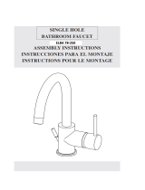
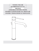
ASSEMBLY INSTRUCTIONS
INSTRUCCIONES PARA EL MONTAJE
AC78CC214TDSISTEX
8” WIDESPREAD
LAVATORY FAUCET

Fig.4 Fig.5
Fig.1
Fig.3
Fig.2
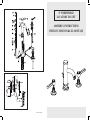
INSTALLATION INSTRUCTIONS
In case of pressures over 5 BAR (~75 PSI), we recommend to use
a pressure reducer. Before proceeding with the assembly, purge
the hot and cold water pipes so as to avoid the accumulation of dirt
and impurities that could affect the function of the faucet.
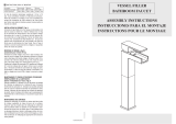
FIG. 1 - Fit the threaded tie-rods (2) on the body (3). Screw the
supply flexible pipes (1) on the faucet (3), the left to the hot water
outlet and the right to the cold water outlet.
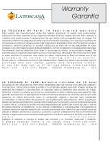
FIG. 2 - Place the base o-ring (2) under the cap (1). From the top
fit the valve, cap, handle and flexible pipe assembly into the basin
hole (making sure to install the red flexible pipe (7) assembly in
the left hole and the blue flexible pipe assembly (19) in the right
hole). From the bottom fit the gasket (4) and the shaped flange
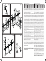
(5) from below the basin, then screw the counter-nut (6) all the
way in. Place the base o-ring (14) and the washer (16) under the
spout (18), then from the top fit the assembly into the central
hole of the basin with the rod (17). Install the gasket (13) and
the flange (12) on the threaded screws (15), then screw the
counter-nuts (11) all the way in. Connect the shower flexible
pipes (10) to the valve flexible pipes (9) using the joint (8). For
the version with waste, install the gasket (24) and fit the drain
(23) into the waste hole (apply some silicon between the drain
and the ceramic surface if necessary), insert the conical gasket
(25) and the anti-friction ring (26), then tighten the assembly
with the nut (27). Make sure to place the gasket (28) and screw
on the waste body (29). Adjust the horizontal control rod (21),
install the clamp (20), connect it to the rod (17) and adjust the
plug (22) movement properly.
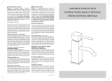
FIG. 3 - Screw the flexible pipe with the red band (1) on the hot
water outlet; screw the flexible pipe with the blue band (2) on the
cold water outlet.
FIG. 4 - To replace the screwdown (6), remove the cap (1),
loosen the screw (2) and pull out the handle (3). Unscrew the
cover (4) and remove the screwdown (6) with the proper wrench,
replace it if necessary and make sure the sealing surfaces of the
gaskets are clean. Reassemble in reverse order making sure to
correctly fit the gasket (5) under the cover (4).
FIG. 5 - We recommend to periodically clean the aerator to prevent
accumulation of debris and limestone which may gradually reduce
the flow. To disassemble the aerator remove the lock nut (1) and
clean the filter (2) from impurities. Reassemble in reverse order
making sure to correctly install the gasket (3).
SURFACE CARE
Before cleaning, make sure the faucet is cold (heat increases
wear out the faucet surface). Do not use products containing
acids or corrosive substances. Wipe the faucet daily with a dry
soft cloth. Do not use steel wool or metal pads, abrasive sponges
or similar products. Rinse off the detergent residues with cold
water after cleaning. Damages to the faucets caused by improper
treatment void the warranty.
“Based on its policy of steady development Paini s.p.a.
reserves the right to change the characteristics of the products
without notice and therefore the images and data contained in
this catalogue may vary.”
INSTRUCCIONES DE INSTALACIÓN
En caso de presiones de funcionamiento superiores a 5 bares
(~75 PSI), se aconseja el uso de un reductor de presión. Antes
de efectuar el montaje, se aconseja purgar las tuberías del agua
caliente y fría para evitar que suciedad y pequeñas impurezas
afecten el funcionamiento del grifo.
FIG. 1 -
Montar en el cuerpo (3) los tirantes roscados (2). Atornillar
los tubos flexibles de alimentación (1) en el grifo (3), el izquierdo al
suministro del agua caliente y el derecho al suministro del agua fría.
FIG. 2 - Posicionar el o-ring de base (2) debajo del capuchón
(1). Introducir desde arriba, en el orificio del sanitario, el bloque
constituido por tubo con racores, capuchón, maneta y tubo flexible
(prestando atención a introducir el bloque con el flexible rojo (7) en
el orificio a la izquierda, y el con el flexible azul (19) en el orificio
a la derecha). Posicionar, por debajo del sanitario, la junta (4) y
la brida perfilada (5), luego atornillar la contratuerca (6) a fondo.
Posicionar el o-ring de base (14) y la arandela (16) debajo de la
boca (18), luego introducir esta última, desde arriba, en el orificio
central del sanitario junto con la varilla (17). Posicionar la junta
(13) e la brida (12) en los tornillos roscados (15), luego atornillar
las contratuercas (11) a fondo. Conectar los tubos flexibles de
la ducha (10) a los tubos flexibles de los tubos con racores (9),
utilizando el racor (8). En caso de versión colocar la junta blanca
(24) e introducir la parte interna del cuerpo del desagüe (23) en el
orificio de desagüe (si es necesario, añadir también silicona entre
la parte interna del cuerpo del desagüe y la cerámica), colocar la
junta cónica (25) y el anillo antifricción (26), luego fijar todo con la
tuerca (27). Asegurarse de la presencia de la junta (28) y atornillar
el cuerpo del desagüe (29). Colocar la varilla de control horizontal
(21) posicionar la abrazadera (20), conectarla a la varilla (17) y
regular correctamente la carrera del tapón (22).
FIG. 3 - Atornillar el tubo flexible con la banda roja (1) al tubo de
suministro de agua caliente; atornillar el flexible con la banda azul
(2) al tubo de suministro de agua fría.
FIG. 4 - Si fuera necesario sustituir el cartucho (6), retirar la
placa (1), destornillar el tornillo (2) y extraer la maneta (1).
Destornillar el capuchón (4) y destornillar el cartucho (6) con
una llave adecuada, sustituirlo, si es necesario, y asegurarse de
que las superficies de estanqueidad de las juntas estén limpias.
Montar nuevamente efectuando las operaciones en sentido
inverso, prestando atención a posicionar correctamente la junta
(5) debajo del capuchón (4).
FIG. 5 - Es oportuno limpiar periódicamente el aireador para evitar
la acumulación de residuos y cal que con el tiempo es causa de
una gradual disminución del caudal. Para efectuar el desmontaje
del aireador destornillar la abrazadera (1) y eliminar las impurezas
del filtro (2). Montar nuevamente procediendo en sentido inverso,
asegurándose de colocar correctamente la junta (3).
MANTENIMIENTO DE LAS SUPERFICIES
Durante la limpieza la superficie del grifo debe estar fría (el calor
acelera el desgaste de la superficie misma). Asegurarse de que
los productos para la limpieza no contengan ácidos o sustancias
corrosivas. El grifo debe ser secado diariamente con un paño
suave. Evitar absolutamente esponjas de acero, esponjas abrasivas
u otros productos similares. Inmediatamente después de la
limpieza, enjuagar bien los residuos de detergente con agua fría.
Los daños a los grifos debidos a un tratamiento no adecuado no
están cubiertos por la garantía.
“Por su política de continuo desarrollo, Paini s.p.a se reserva el
derecho de modificar las características de los productos sin ningún
aviso previo; por tanto, las imágenes y los datos contenidos en el
presente catálogo deben considerarse a título indicativo”.
GB
Water Supply Recommended Max Min
Hot water temperature 65 C° (~150F) 80 C° (~175F) 15 C° (~60F)
Working pressure 3 BAR (~45PSI) 5 BAR (~75PSI) 0.5 BAR (~7PSI)
ES
Alimentación Recomendada Máxima Mínima
Temperatura agua caliente 65 C° (~150F) 80 C° (~175F) 15 C° (~60F)
Presión de funcionamiento
3 BARES (~45PSI) 5 BARES (~75PSI) 0.5 BAR (~7PSI)
-
 1
1
-
 2
2


LaToscana 88CR214 Guía de instalación
- Categoría
- Artículos sanitarios
- Tipo
- Guía de instalación
en otros idiomas
- English: LaToscana 88CR214 Installation guide
Artículos relacionados


Otros documentos
-
Glacier Bay 78PW557PELFHD Guía de instalación
-
Fortis 9210200BN Guía de instalación
-
-
-
-
-
-
-
-
 La Toscana L3012 Guía de instalación
