
20137240 (5) - 12/2022
Installation, use and maintenance instructions
Instrucciones de instalación, uso y mantenimiento
Light oil burners
Quemadores de gasóleo
Two stage operation
Funcionamiento a 2 llamas
CODE - CÓDIGO MODEL - MODELO TYPE - TIPO
20015693 BG6.1D 985T
20015694 BG6.1D 985T
20015696 BG7.1D 986T
GB
E

Translation of the original instructions
Traducción de las instrucciones originales

1 20137240
GB
Contents
1 Declaration.................................................................................................................................................................................. 3
2 Information and general warnings............................................................................................................................................ 4
2.1 Information about the instruction manual .................................................................................................................... 4
2.1.1 Introduction.................................................................................................................................................................. 4
2.1.2 General dangers.......................................................................................................................................................... 4
2.1.3 Other symbols ............................................................................................................................................................. 4
2.1.4 Delivery of the system and the instruction manual...................................................................................................... 5
2.2 Guarantee and responsibility....................................................................................................................................... 5
3 Safety and prevention................................................................................................................................................................ 6
3.1 Background ................................................................................................................................................................. 6
3.2 Personnel training ....................................................................................................................................................... 6
4 Technical description of the burner ......................................................................................................................................... 7
4.1 Burner designation ...................................................................................................................................................... 7
4.2 Models available.......................................................................................................................................................... 7
4.3 Technical data............................................................................................................................................................. 8
4.4 Electrical data.............................................................................................................................................................. 8
4.5 Maximum dimensions.................................................................................................................................................. 9
4.6 Burner equipment........................................................................................................................................................ 9
4.7 Burner description ..................................................................................................................................................... 10
4.8 Firing rate (EN 267)................................................................................................................................................... 11
4.8.1 Commercial boilers.................................................................................................................................................... 11
4.8.2 Test boiler.................................................................................................................................................................. 11
4.9 Electrical control box ................................................................................................................................................. 12
5 Installation ................................................................................................................................................................................ 13
5.1 Notes on safety for the installation ............................................................................................................................ 13
5.2 Instructions to avoid burnout or bad combustion of the burner ................................................................................. 13
5.3 Handling .................................................................................................................................................................... 13
5.4 Preliminary checks .................................................................................................................................................... 14
5.5 Operating position ..................................................................................................................................................... 14
5.6 Securing the burner to the boiler............................................................................................................................... 15
5.7 Adjusting the choke................................................................................................................................................... 16
5.8 Combustion head adjustment.................................................................................................................................... 16
5.9 Air damper and 1st stage and 2nd stage pressure pump adjustment....................................................................... 17
5.9.1 1st stage adjustment ................................................................................................................................................. 17
5.9.2 2nd stage adjustment................................................................................................................................................ 17
5.10 Flame sensor adjustment.......................................................................................................................................... 17
5.11 Electrodes setting...................................................................................................................................................... 18
5.12 Maintenance position ................................................................................................................................................ 19
5.13 Hydraulic systems ..................................................................................................................................................... 20
5.13.1 Combustion supply.................................................................................................................................................... 20
5.13.2 Pump ..............................................................................................................................................................................................................................................................................................20
5.13.3 Pressurised one-pipe systems .................................................................................................................................. 21
5.13.4 Priming pump ............................................................................................................................................................ 21
6 Start-up, calibration and operation of the burner ................................................................................................................. 22
6.1 Notes on safety for the first start-up .......................................................................................................................... 22
6.2 Combustion adjustment............................................................................................................................................. 22
6.3 Recommended nozzles............................................................................................................................................. 23
6.4 Electrical system ....................................................................................................................................................... 24
6.5 Electrical diagram...................................................................................................................................................... 25
6.6 Operating programme ............................................................................................................................................... 26
6.7 Table of times............................................................................................................................................................ 27

20137240 2
GB
Contents
6.7.1 Operating status indication ........................................................................................................................................27
6.7.2 Fault diagnostics - lockouts........................................................................................................................................28
6.7.3 Shut-down test ...........................................................................................................................................................28
6.7.4 Intermittent operation .................................................................................................................................................28
6.7.5 Recycle and limit of repetitions ..................................................................................................................................28
6.7.6 Presence of an extraneous light or parasite flame.....................................................................................................29
6.7.7 Pre and post-ignition of the discharge of the ignition transformer..............................................................................29
6.7.8 Reset by button and remotely of the burner...............................................................................................................29
6.7.9 Protection reset..........................................................................................................................................................29
6.7.10 Reset button/Remote reset fault ................................................................................................................................29
6.7.11 External lockout signal (S3) .......................................................................................................................................29
6.7.12 Hour counter function (B4).........................................................................................................................................29
6.7.13 Monitoring the power supply voltage .........................................................................................................................30
6.7.14 Frequency supply error ..............................................................................................................................................30
6.7.15 Internal voltage fault...................................................................................................................................................30
6.7.16 Checking the fan motor..............................................................................................................................................30
6.7.17 EEprom check............................................................................................................................................................30
6.7.18 Checking the electronic control circuit of the 1st stage valve ....................................................................................30
6.7.19 Checking the electronic control circuit of the 2nd stage valve ...................................................................................30
6.7.20 Checking the short-circuit of the 1st stage valve .......................................................................................................30
6.7.21 Long pre-purging........................................................................................................................................................30
6.7.22 Post-purging...............................................................................................................................................................31
6.7.23 Continuous purging....................................................................................................................................................31
6.7.24 Lockout log.................................................................................................................................................................31
6.7.25 Logging of burner operating parameters....................................................................................................................31
6.7.26 Admissible lengths of the external connections to the burner....................................................................................31
6.8 Programming menu ...................................................................................................................................................32
6.8.1 General notes ............................................................................................................................................................32
6.8.2 Block diagram for entering the menu .........................................................................................................................32
6.8.3 Shut-down test ...........................................................................................................................................................33
6.8.4 Post-purging and continuous purging ........................................................................................................................33
6.8.5 Intermittent operation .................................................................................................................................................33
6.8.6 Setting the opening delay of the 2nd stage................................................................................................................33
6.8.7 Setting a long pre-purging..........................................................................................................................................33
6.8.8 Displaying the lockout log ..........................................................................................................................................34
6.8.9 Resetting the programming menu parameters and the lockout log ...........................................................................34
6.9 Lockout types.............................................................................................................................................................35
7 Maintenance ..............................................................................................................................................................................36
7.1 Notes on safety for the maintenance .........................................................................................................................36
7.2 Maintenance programme ...........................................................................................................................................36
7.2.1 Maintenance frequency..............................................................................................................................................36
7.2.2 Checking and cleaning...............................................................................................................................................36
8 Faults / Solutions ......................................................................................................................................................................37
9 Appendix - Accessories ...........................................................................................................................................................38

3 20137240
GB
Declaration
1 Declaration
Declaration of Conformity A.R. 8/1/2004 & 17/7/2009 – Belgium
Manufacturer: RIELLO S.p.A.
37045 Legnago (VR) Italy
Tel. ++39.0442630111
www.riello.com
Distributed by: VAN MARCKE HQ
LAR Blok Z 5,
B-8511 Kortrijk (Aalbeke) Belgio
Tel. +32 56 23 7511
e-mail: [email protected]
URL. www.vanmarcke.com
This document certifies that the series of devices specified below is in compliance with the model described in the EC Declaration of
Conformity and has been manufactured and distributed in compliance with the requirements defined in the Legislative Decree of
January 8th 2004 and July 17th 2009.
Product type: Light oil burner
Model: BG6.1D
BG7.1D
Regulation applied: EN 267 and A.R. of January 8th 2004 - July -17th 2009
Values measured: BG6.1D
BG7.1D
Max. CO: 5 mg/kWh
Max. NOx: 81 mg/kWh
Max. CO: 1 mg/kWh
Max. NOx: 78 mg/kWh
Manufacturer's Declaration
RIELLO S.p.A. declares that the following products comply with the NOx emission limits specified by German standard “1. BIm-
SchV revision 26.01.2010”.
Product Type Model Output
Light oil burners 985T BG6.1D 53.8 - 104 kW
986T BG7.1D 77.7 - 149.5 kW

20137240 4
GB
Information and general warnings
2.1 Information about the instruction manual
2.1.1 Introduction
The instruction manual supplied with the burner:
is an integral and essential part of the product and must not
be separated from it; it must therefore be kept carefully for
any necessary consultation and must accompany the burner
even if it is transferred to another owner or user, or to
another system. If the manual is lost or damaged, another
copy must be requested from the Technical Assistance Cen-
tre of the area;
is designed for use by qualified personnel;
offers important indications and instructions relating to the
installation safety, start-up, use and maintenance of the
burner.
Symbols used in the manual
In some parts of the manual you will see triangular DANGER
signs. Pay great attention to these, as they indicate a situation of
potential danger.
2.1.2 General dangers
The dangers can be of 3 levels, as indicated below.
2.1.3 Other symbols
Abbreviations used
Ch. Chapter
Fig. Figure
Page Page
Sec. Section
Tab. Table
2 Information and general warnings
DANGER
Maximum danger level!
This symbol indicates operations which, if not car-
ried out correctly, cause serious injury, death or
long-term health risks.
WARNING
This symbol indicates operations which, if not car-
ried out correctly, may cause serious injury, death
or long-term health risks.
CAUTION
This symbol indicates operations which, if not car-
ried out correctly, may cause damage to the ma-
chine and/or injury to people.
DANGER
DANGER: LIVE COMPONENTS
This symbol indicates operations which, if not car-
ried out correctly, lead to electric shocks with le-
thal consequences.
DANGER: FLAMMABLE MATERIAL
This symbol indicates the presence of flammable
materials.
DANGER: BURNING
This symbol indicates the risks of burns due to
high temperatures.
DANGER: CRUSHING OF LIMBS
This symbol indicates the presence of moving
parts: danger of crushing of limbs.
WARNING: MOVING PARTS
This symbol indicates that you must keep limbs
away from moving mechanical parts; danger of
crushing.
DANGER: EXPLOSION
This symbol signals places where an explosive at-
mosphere may be present. An explosive atmos-
phere is defined as a mixture - under atmospheric
conditions - of air and flammable substances in
the form of gases, vapours, mist or dust in which,
after ignition has occurred, combustion spreads to
the entire unburned mixture.
PERSONAL PROTECTION EQUIPMENT
These symbols indicate the equipment that must
be worn and kept by the operator for protection
against threats against safety and/or health while
at work.
OBLIGATION TO ASSEMBLE THE COVER AND
ALL THE SAFETY AND PROTECTION DEVICES
This symbol signals the obligation to reassemble
the cover and all the safety and protection devices
of the burner after any maintenance, cleaning or
checking operations.
ENVIRONMENTAL PROTECTION
This symbol gives indications for the use of the
machine with respect for the environment.
IMPORTANT INFORMATION
This symbol indicates important information that
you must bear in mind.
This symbol indicates a list.

5 20137240
GB
Information and general warnings
2.1.4 Delivery of the system and the instruction
manual
When the system is delivered, it is important that:
the instruction manual is delivered to the user by the system
manufacturer, with the recommendation to keep it in the
room where the heat generator is to be installed.
The instruction manual shows:
– the serial number of the burner;
– the address and telephone number of the nearest Assis-
tance Centre.
The system supplier must carefully inform the user about:
– the use of the system;
– any further tests that may be required before activating the
system;
– maintenance, and the need to have the system checked at
least once a year by a representative of the manufacturer
or another specialised technician.
To ensure a periodic check, the manufacturer recom-
mends the drawing up of a Maintenance Contract.
2.2 Guarantee and responsibility
The Manufacturer guarantees its new products from the date of
installation, in accordance with the regulations in force and/or the
sales contract. At the moment of the first start-up, check that the
burner is integral and complete.
In particular, the rights to the guarantee and the responsibility will
no longer be valid, in the event of damage to things or injury to
people, if such damage/injury was due to any of the following
causes:
incorrect installation, start-up, use and maintenance of the
burner;
improper, incorrect or unreasonable use of the burner;
intervention of unqualified personnel;
carrying out of unauthorised modifications on the appliance;
use of the burner with safety devices that are faulty, incor-
rectly applied and/or not working;
installation of untested supplementary components on the
burner;
powering of the burner with unsuitable fuels;
faults in the fuel supply system;
use of the burner even following an error and/or an irregular-
ity;
repairs and/or overhauls incorrectly carried out;
modification of the combustion chamber with inserts that
prevent the regular development of the structurally estab-
lished flame;
insufficient and inappropriate surveillance and care of those
burner components most likely to be subject to wear and
tear;
use of non-original components, including spare parts, kits,
accessories and optionals;
force majeure.
The manufacturer furthermore declines any and every re-
sponsibility for the failure to observe the contents of this
manual.
.........................................................................................
.........................................................................................
.........................................................................................
.........................................................................................
WARNING
Failure to observe the information given in this
manual, operating negligence, incorrect installa-
tion and carrying out of non authorised modifica-
tions will result in the annulment by the
manufacturer of the guarantee that it supplies with
the burner.

20137240 6
GB
Safety and prevention
3.1 Background
The burners have been designed and built in compliance with
current regulations and directives, applying the known technical
rules of safety and envisaging all the potential danger situations.
It is necessary, however, to bear in mind that the imprudent and
clumsy use of the equipment may lead to situations of death risk
for the user or third parties, as well as the damaging of the burner
or other items. Inattention, thoughtlessness and excessive confi-
dence often cause accidents; the same applies to tiredness and
sleepiness.
It is a good idea to remember the following:
The burner must only be used as expressly described. Any
other use should be considered improper and therefore dan-
gerous.
Namely:
it can be applied to boilers operating with water, steam, diather-
mic oil, and to other uses expressly named by the manufacturer;
the type and pressure of the fuel, the voltage and frequency of the
electrical power supply, the minimum and maximum deliveries for
which the burner has been regulated, the pressurisation of the
combustion chamber, the dimensions of the combustion cham-
ber and the ambient temperature must all be within the values in-
dicated in the instruction manual.
Modification of the burner to alter its performance and desti-
nations is not allowed.
The burner must be used in exemplary technical safety con-
ditions. Any disturbances that could compromise safety must
be quickly eliminated.
Opening or tampering with the burner components is not
allowed, apart from the parts requiring maintenance.
Only those parts envisaged by the manufacturer can be
replaced.
3.2 Personnel training
The user is the person, body or company that has acquired the
machine and intends to use it for the specific purpose. He is re-
sponsible for the machine and for the training of the people work-
ing around it.
The user:
undertakes to entrust the machine exclusively to suitably
trained and qualified personnel;
undertakes to inform his personnel in a suitable way about
the application and observance of the safety instructions.
With that aim, the user undertakes to ensure that everyone
knows the use and safety instructions for his own duties.
Personnel must follow all the danger and caution indications
shown on the machine.
Personnel must not carry out, on their own initiative, opera-
tions or interventions that are not within their province.
Personnel are obliged to inform their superiors of every
problem or dangerous situation that may arise.
The assembly of parts of other makes, or any modifications,
can alter the characteristics of the machine and hence com-
promise operating safety. The manufacturing company
therefore accepts no responsibility whatsoever for any which
may result from the use of non-original parts.
In addition:
3 Safety and prevention
WARNING
The manufacturer guarantees safety and proper
functioning only if all burner components are intact
and positioned correctly.
the user must take all the measures neces-
sary to prevent unauthorised people gaining
access to the machine;
the user must inform the manufacturer if
faults or malfunctioning of the accident pre-
vention systems are noticed, along with any
presumed danger situation;
personnel must always use the personal pro-
tective equipment envisaged by legislation
and follow the indications given in this man-
ual.

7 20137240
GB
Technical description of the burner
4.1 Burner designation
4.2 Models available
Tab. A
4 Technical description of the burner
Designation Combustion head Voltage Code
BG6.1D TC 1/230/50 20015693
BG6.1D TL 1/230/50 20015694
BG7.1D TC 1/230/50 20015696
Range:
Size
Fuel: Natural gas
Light oil
Variations:
Electrical power 1/230/50
1/220/60
B G 6.1 1/230/50
BASIC DESIGNATION
EXTENDED DESIGNATION
1/230V/50Hz
1/220V/60Hz
K Conical head
M Ignition with reduced flow rate
R Light oil pre-heater
S
G
Head: TC Standard head
TL Extended head
of the system:
Standard Emission
Low NOx
R
B
TL
DTwo-stage
D

20137240 8
GB
Technical description of the burner
4.3 Technical data
Tab. B
(1) Reference conditions: Ambient temperature 20°C - Barometric pressure 1013 mbar - Altitude 0 m a.s.l. (Hi = 11.86 kWh/kg)
(2) Sound pressure measured in manufacturer's combustion laboratory, with burner operating on test boiler and at maximum output. The sound power
is measured with the “Free Field” method, as per EN 15036, and according to an accurate “Accuracy: Category 3” measurement, as described in
EN ISO 3746.
4.4 Electrical data
Tab. C
Model BG6.1D BG7.1D
Delivery (1)
Thermal power (1)
kg/h
kW
4.5 / 5.5 8.7
53.8 / 65.8 104
6.5 / 7.7 12.5
77.7 / 92.0 149.5
Fuel Light oil, viscosity 4 6 mm2/s at 20°C
Operation Intermittent (FS1)
Use Boilers: water and diathermic oil
Ambient temperature °C 0 - 40
Combustion air temperature °C max 40
Pump bar Pressure: 8 15
Noise levels (2) Sound pressure
Sound power dB (A) 63
74
69
80
Burner weight kg 20 20
Model BG6.1D BG7.1D
Electrical power Single-phase, ~ 50Hz 230V ± 10%
Motor A
rpm
rad/s
1.8
2800
294
1.9
2720
288
Capacitor F6.3 8.0
Ignition transformer Secondary 18 kV - 25 mA
Absorbed electric power kW 0.39 0.47
Protection level IP40

9 20137240
GB
Technical description of the burner
4.5 Maximum dimensions
The maximum dimensions of the flange and burner are given in Fig. 1.
Tab. D
4.6 Burner equipment
Flange with insulating gasket ..............................................No. 1
Screw and nuts for flange....................................................No. 1
Remote reset connection .................................................... No. 1
Screws and nuts for fixing the flange to the boiler............... No. 4
Flexible hoses with nipples..................................................No. 2
4 pin plug.............................................................................No. 1
7 pin plug.............................................................................No. 1
Recirculating pipe................................................................No. 1
Installer booklet ...................................................................No. 1
Spare Parts List................................................................... No. 1
Remote reset kit
The burner has a remote reset kit (RS) consisting of a con-
nection and a push-button operating at a distance of 20
metres max.
In order to install it, remove the safety lockout device installed
at the factory and insert the lockout supplied with the burner
(see electrical diagram).
Fig. 1
L
O
P
11
N
M
45°
45°
A
B
C
DE
F
G
Ø H Ø I
N
D9675
Model A B C D E F G Ø HØ I L M N O P
BG6.1D 300 345 285 228 284 12 36 97 131 189 106 83 140 170
BG6.1D TL 300 345 285 228 363 12 36 97 131 189 106 83 140 170
BG7.1D 300 345 285 247 394 12 36 116 165 213 127 99 160 190

20137240 10
GB
Technical description of the burner
4.7 Burner description
Two-stage light oil burner with low pollutant emissions (Nitric Oxide NOx, Carbon monoxide CO and unburned Hydrocarbons).
1 Pressure variator pump
2 Recirculating pipe
3 Control box
4 Reset button with lock-out signal
5 Flange with insulating gasket
6 2nd stage air damper adjustment assembly
7 Nozzle-holder assembly
8 Flame sensor
9 Hydraulic jack
10 4 pole socket
11 2nd stage valve
12 1st stage valve
13 Choke
14 Motor
15 Combustion head
16 1st stage damper adjustment assembly
Fig. 2
D9642
674
1
8
14
3
2
5
15
10
9
11
12
13
16

11 20137240
GB
Technical description of the burner
4.8 Firing rate (EN 267)
The burner output is chosen from within the diagram area
(Fig. 3).
4.8.1 Commercial boilers
The burner-boiler combination poses no problems if the boiler
conforms to EN 303 and its combustion chamber dimensions are
similar to those provided in EN 267.
If, on the other hand, the burner is combined with a commercial
boiler that does not conform to EN 303, or where the combustion
chamber is much smaller than the dimensions set out in EN 267,
please contact the manufacturers.
4.8.2 Test boiler
The firing rate has been defined on test boilers according to EN
267 standard.
WARNING
To ensure the burner works correctly, start-ups
should always occur within the relative firing rate.
WARNING
The firing rates (Fig. 3) were obtained at an ambi-
ent temperature of 20 °C, at a barometric pressure
of 1013 mbar (about 0 m a.s.l.) and with the com-
bustion head regulated as indicated on 22.
Fig. 3
Light oil output – kg/h
Heat output – kW
Pressure in the combustion
chamber – mbar
50 60 70 80 90 100 110 120 130 140 150
456789
10 11 12 13
2,6
2,4
2,2
2,0
1,8
1,6
1,4
1,2
1,0
0,8
0,6
0,4
0,2
0
0,3
0,2
D9674
EN 303-2
BG7.1D
BG6.1D - BG6.1D TL

20137240 12
GB
Technical description of the burner
4.9 Electrical control box
The control box is a control and supervision system for forced
draught burners, for intermittent operation (at least one controlled
shutdown every 24 hours).
Important notes
All interventions (assembly and installation operations,
assistance, etc.) must be carried out by qualified personnel.
Before modifying the wiring in the control box connection
area, fully disconnect the system from the power supply
(omnipolar separation).
Protection against electrocution from the control box and all
connected electric components is obtained with the correct
assembly.
Before any intervention (assembly and installation opera-
tions, assistance, etc.), ensure the wiring is in order and that
the parameters are correctly set, then make the safety
checks.
Falls and collisions can negatively affect the safety func-
tions. In this case, the control box must not be operated,
even if it displays no evident damage.
For safety and reliability, comply with the following instruc-
tions:
– avoid conditions that can favour the development of conden-
sate and humidity. Otherwise, before switching on again,
make sure the control box is perfectly dry.
– Static charges must be avoided since they can damage the
control box’s electronic components when touched.
Installation notes
• Check the electrical wiring inside the boiler complies with the
national and local safety regulations.
• Install switches, fuses, earth connection etc. in compliance
with local regulations.
• Do not confuse the powered conductors with the neutral
ones.
• Ensure that spliced wires cannot get into contact with neigh-
bouring terminals. Use adequate ferrules.
• Arrange the H.V. ignition cables separately, as far as possi-
ble from the control box and the other cables.
• When wiring the unit, make sure the 230V AC mains voltage
cables are run strictly separate from extra low-voltage cables,
to avoid the risk of electrocution.
To remove the control box from the burner it is necessary to
Fig. 4:
disconnect all the connectors connected to it, all the plugs,
the high voltage cables and the earth wire (TB);
unscrew the screw (A) and pull the control box in the direc-
tion of the arrow.
To install the control box it is necessary to:
tighten the screw (A) with a tightening torque of 1 - 1.2 Nm;
reconnect all previously disconnected connectors, making
sure to connect the 7 pin plug as the final step.
NOTE:
The burners have been approved for intermittent operation.
This means that they must stop once every twenty four
hours to permit the electrical control box to check its effi-
ciency at start-up. The boiler limit thermostat (TL) normally
ensures the stopping of the burner. If this is not the case, it
is necessary to apply a timer switch in series to the limit
thermostat (TL) that turns off the burner at least once every
24 hours.
Electrical wiring of the flame sensor
It is important for signal transmission to be almost totally free
of any disturbances or loss:
• Always separate the flame sensor cables from the other ca-
bles:
– the line capacity reduces the magnitude of the flame sig-
nal.
Technical data
Tab. E
WARNING
To avoid accidents, material or environmental
damage, observe the following instructions!
The control box is a safety device! Avoid opening
or modifying it, or forcing its operation. The Man-
ufacturer cannot assume any responsibility for
damage resulting from unauthorised work!
Mains voltage AC 210...230 V -15 % / +10 %
Mains frequency 50/60 Hz ±6 %
Built-in fuse T4A 250V
Energy consumption 40 VA
Protection level IP00
Fig. 4
E9275
A

13 20137240
GB
Installation
5.1 Notes on safety for the installation
After carefully cleaning all around the area where the burner is to
be installed, and arranging for the environment to be illuminated
correctly, proceed with the installation operations.
5.2 Instructions to avoid burnout or bad combustion of the burner
1 The burner can not be installed outside as it is suitable for
operation in closed rooms only.
2 The premises the burner operates in must have openings
for the air need for the combustion.
To be sure about this, you have to control CO2 and CO in
the exhaust gases with all the windows and doors closed.
3 If there are air extractors in the premises the burner works,
make sure that there are openings for air to be taken in that
are big enough to ensure the required air change; In any
case, check that when the burner stops the extractors do
not draw hot fumes from pipes through the burner.
4 When the burner is stopped, the flue must be kept open and
a natural draft created in the combustion chamber.
If the smoke pipe is closed, the burner must be drawn back
till the extraction of blast tube from the furnace. Before oper-
ating in this way take the voltage off.
5.3 Handling
The transport weight is given in chapter "Technical data" on page
8.
Observe the permissible ambient temperatures for storage and
transport: -20... + 70 °C, with max. relative air humidity 80%.
5 Installation
DANGER
All the installation, maintenance and disassembly
operations must be carried out with the electricity
supply disconnected.
WARNING
The installation of the burner must be carried out
by qualified personnel, as indicated in this manual
and in compliance with the standards and regula-
tions of the laws in force.
DANGER
Combustion air inside the boiler must be free from
hazardous mixes (e.g.: chloride, fluoride, halo-
gen); if present, it is highly recommended to carry
out cleaning and maintenance more frequently.
After positioning the burner near the installation
point, correctly dispose of all residual packaging,
separating the various types of material.
CAUTION
Before proceeding with the installation operations,
carefully clean all around the area where the burn-
er will be installed.
The operator must use the required equipment
during installation.

20137240 14
GB
Installation
5.4 Preliminary checks
Checking the consignment
Checking the characteristics of the burner
Check the identification label (Fig. 5) of the burner, showing:
the model A) (Fig. 5) and type of burner B);
the year of manufacture, in cryptographic form C);
the serial number D);
the electrical power consumption E);
the types of fuel used and the relative supply pressures F);
the data of the burner's minimum and maximum output pos-
sibilities G) (see Firing rate).
5.5 Operating position
CAUTION
After removing all the packaging, check the integ-
rity of the contents. In the event of doubt, do not
use the burner; contact the supplier.
The packaging elements (wooden cage or card-
board box, nails, clips, plastic bags, etc.) must not
be abandoned as they are potential sources of
danger and pollution; they should be collected and
disposed of in the appropriate places.
WARNING
The output of the burner must be within the
boiler's firing rate.
WARNING
A burner label that has been tampered with, re-
moved or is missing, along with anything else that
prevents the definite identification of the burner
makes any installation or maintenance work diffi-
cult.
Fig. 5
D9370
WARNING
The burner is designed to work only in the posi-
tions, 1 and 2.
Installation 1 is preferable, as it is the only one that
allows the maintenance operations as described
in this manual.
The installations 2 allows it to operate but not with
maintenance with hooking to the boiler.
Any other position could compromise the correct
operation of the appliance.
WARNING
Any other positioning could compromise the cor-
rect operation of the appliance.
Installations 3, 4 and 5 are forbidden for safety
reasons.
Fig. 6
D7088
1 2 3 4 5

15 20137240
GB
Installation
5.6 Securing the burner to the boiler
To install the burner on the boiler, do the following:
insert the screw and two nuts 9) on the flange 1)(Fig. 9).
If necessary, widen the holes of the insulating gasket
4)(Fig. 7).
Fix the flange 1) to the boiler door 3) using the screws 5) and
(if necessary) the nuts 2) interposing the insulating gasket
4)(Fig. 10).
Open the boiler door and insert the choke 9) on the recircu-
lating pipe 6), adjusting it according to the calibrations in
Tab. H, on page 22;
Insert the recirculating pipe 6) on the blast tube of the burner
7), and fix it with the nut 8)(Fig. 10).
NOTE:
when the installation is complete, check the burner is slight-
ly tilted, as shown in Fig. 8.
Provide an adequate lifting system of the burner.
WARNING
In any event, make sure that the combustion head
crosses the entire thickness of the boiler door and
it should be a maximum of 180 mm.
Refractory lining included.
WARNING
The seal between burner and boiler must be
airtight.
Fig. 7
D5012
4
Fig. 8
D5025
Fig. 9
9
1
D9618
9
Fig. 10
D9619
7
5
4
3
1
6
9
5
28

20137240 16
GB
Installation
5.7 Adjusting the choke
In certain applications, for example on boilers with three flue gas
passes or systems with particularly long flues, or flues with a wide
section, flame instability is possible due to the excessive recircu-
lation of flue gases through the recirculating pipe 1)(Fig. 11).
In these cases it is possible to adjust the choke 2)(Fig. 11) to re-
duce the section through which the flue gases pass, referring to
Tab. H page 22.
5.8 Combustion head adjustment
The adjustment of the combustion head varies depending on the
burner output.
Do the following to adjust it:
Turn the adjustment screw 2)(Fig. 12) clockwise or anti-clock-
wise until the notch on the regulating rod 3)(Fig. 12) lines up with
the outer surface of the nozzle-holder assembly 1)(Fig. 12).
Example:
the regulating rod 3)(Fig. 12) is calibrated to notch 2.5; this
means that the burner is adjusted for an output of 5.3kg/h with the
pump pressure at 9 bar and with the use of a 1.50 GPH nozzle,
as indicated in Tab. H page 22.
21
mm
Fig. 11
D9687
Fig. 12
S7995
1
3
2

17 20137240
GB
Installation
5.9 Air damper and 1st stage and 2nd stage pressure pump adjustment
5.9.1 1st stage adjustment
Air damper adjustment
Loosen the nut 1)(Fig. 13), turn the screw 2)(Fig. 13), and
bring the indicator 3)(Fig. 13) to the required position.
When the adjustment is completed screw in the nut
1)(Fig. 13).
Pump pressure adjustment
The pump leaves the factory set at 9 bar.
If necessary, recalibrate the pressure using the screw 7)(Fig. 13).
The pressure gauge for checking the pressure should be fitted in
the place of the plug 8)(Fig. 13).
5.9.2 2nd stage adjustment
Air damper adjustment
Loosen the nut 4)(Fig. 13), adjust the screw 5)(Fig. 13), and
bring the indicator 6)(Fig. 13) to the required position.
When the adjustment is completed screw in the nut
4)(Fig. 13).
For the burners BG6.1D and BG6.1D TL when the burner
stops, the air damper closes automatically to a max. depres-
sion at the flue of 0.5 mbar.
For the BG7.1D when the burner stops, the air damper
remains open at the position of the 1st stage.
Pump pressure adjustment
The pump leaves the factory set at 15 bar.
If necessary, recalibrate the pressure using the screw 9)(Fig. 13).
The pressure gauge for checking the pressure should be fitted in
the place of the plug 8)(Fig. 13).
5.10 Flame sensor adjustment
The flame sensor leaves the factory calibrated to position 4.
It consists of:
a potentiometer 3)(Fig. 14) for adjusting the sensitivity.
Led 1)(Fig. 14) indicates the sensitivity.
Led 2)(Fig. 14) indicates its operation.
To adjust, proceed as follows:
turn the indicator of the potentiometer 3)(Fig. 14) anticlock-
wise until the LED 1)(Fig. 14) blinks, thereby defining the
minimum value of the notch.
Turn the indicator of the potentiometer 3)(Fig. 14) clockwise
until the LED 1)(Fig. 14)is on and fixed.
Consider the setting final as the minimum value detected by
increasing by one or two notches.
After a pause of at least five minutes, check that this adjust-
ment permits the proper start up of the burner.
Fig. 13
S7915
5
2
3
4
6
1
7
9
8
WARNING
During pre-purging the LEDs (1 and 2) stay
off.
Permanent operation is indicated when both
LEDs are lit up.
Fig. 14
Blue
Brown
Black
S7903
1
2
3

20137240 18
GB
Installation
5.11 Electrodes setting
Rest the diffuser disc-holder assembly 1)(Fig. 15) against
the nozzle holder 2) and lock it with the screw 3)(Fig. 15).
For any adjustments, loosen the screw 4) and move the
electrode assembly 5).
To access the electrodes carry out the operation described,
see paragraph “Operating position” on page 14.
WARNING
These dimensions Fig. 15 must be respected.
Model
BG6.1D - BG6.1D TL
BG7.1D
A
4.5 0
- 0.5 mm
4.5 + 0.5
0mm
A
Fig. 15
D5417
4
5
3 12
4.5 0 mm
+ 0.5

19 20137240
GB
Installation
5.12 Maintenance position
To access the nozzle carry out the following operations (Fig. 16):
remove the wires 1) from the control box, the flame sensor
2)(Fig. 16) and loosen the nut 3) from the pump.
Loosen the screws 4) and extract the nozzle-holder assem-
bly 5) by turning to the right.
Remove the wires 1) from the electrodes, loosen the screw
3)(Fig. 15), and take the diffuser disc holder assembly 6) out
of the nozzle-holder assembly 5).
Change the nozzle 7)(Fig. 16), holding the nozzle-holder
with the help of a spanner.
Screw on the nozzle 7) while holding the nozzle holder still
with a spanner.
Refit following the operations in the reverse order to the one
described above.
WARNING
Having put back the nozzle-holder assembly,
screw in the nut 3), as shown in Fig. 17.
1
2
5
6
3
4
7
89
5
Fig. 16
S9668
D5684
Fig. 17
TIGHTEN WITHOUT
MOVING TO THE END

20137240 20
GB
Installation
5.13 Hydraulic systems
5.13.1 Combustion supply
The burner is designed to allow entry of the flexible oil lines on
either side of the burner.
Depending on whether the pipe outlet is to the right or left of the
burner, it will be necessary to invert both the fixing plate 1) and
the closing bracket 2)(Fig. 18).
5.13.2 Pump
Before starting up the burner, make sure that the return pipeline
is not clogged.
An excessive back pressure ( 1 bar) would cause the damage
of the pump seal, with subsequent fuel leaks inside the burner.
The pump is designed to allow working with two pipes.
For single-pipe operation it is necessary to unscrew the return
plug 2)(Fig. 19), remove the by-pass screw 3)(Fig. 19) and then
screw in the plug 2)(Fig. 19).
Key (Fig. 19)
1 Suction line
2 Return line
3 By-pass screw
4 Gauge connection
5 2nd stage pressure adjuster
6 Vacuum gauge connection
7 1st stage pressure adjuster
8 Pressure variator piston
9 2nd stage valve
10 1st stage valve
11 Auxiliary pressure test point
Explosion danger due to fuel leaks in the pres-
ence of a flammable source.
Precautions: avoid knocking, attrition, sparks and
heat.
Make sure that the fuel interception tap is closed
before performing any operation on the burner.
WARNING
The fuel supply line must be installed by qualified
personnel, in compliance with current standards
and laws.
Fig. 18
D5345
11
2
WARNING
The closure plug of the oil supply (Suction line
1)(Fig. 19) is made of plastic.
Once removed, you must throw it away and not re-
use it under any circumstances.
In one-pipe systems, the plug supplied on the re-
turn line 2)(Fig. 19) of the pump is made of steel.
It is very important that the steel plug is used
only for this purpose.
WARNING
Check periodically the flexible pipes conditions.
Fig. 19
12
D9709
10 9
78
11
1
2
3
4
5
6

21 20137240
GB
Installation
5.13.3 Pressurised one-pipe systems
Pressurised one-pipe systems (Fig. 20) have a positive fuel pres-
sure on intake to the burner.
Usually the tank is higher than the burner, or the fuel pumping
systems are on the outside of the boiler.
In order to obtain one pipe working it is necessary to unscrew the
return plug 2)(Fig. 19, on page 20), remove the by-pass screw 3)
and then screw the plug 2) in again with a tightening torque of 0.5
Nm.
Tab. F
H= Difference of level
L= Maximum suction line length
Ø= Inner diameter of the pipe
5.13.4 Priming pump
In the systems A and B of Fig. 21 start the burner and wait for the
priming.
Should lockout occur prior to the arrival of the fuel, await at least
20 seconds before repeating the operation.
The pump vacuum should not exceed a maximum of 0.4 bar (30
cm Hg).
Beyond this limit gas is released from the oil.
In vacuum systems B (Fig. 21) we recommend bringing the re-
turn line to the same height as the suction line.
In this case a foot valve is not required.
Should however the return line arrive over the fuel level, a foot
valve is required.
This solution however is less safe than previous one, due to the
possibility of leakage of the valve.
H= Difference of level
L= Maximum suction line length
Ø= Inner diameter of the pipe
Tab. G
H
metres
L metres
Ø (8 mm) Ø (10 mm)
0.5 10 20
120 40
1.5 40 80
260 100
max. 4 m
D5414
Fig. 20
H
WARNING
The pipes must all be perfectly sealed.
Fig. 21
D5415
AB
H
max. 4 m
max. 4 m
H
H
H
H
metres
L metres
Ø (8 mm) Ø (10 mm)
035 100
0.5 30 100
125 100
1.5 20 90
215 70
3 8 30
3.5 620

20137240 22
GB
Start-up, calibration and operation of the burner
6.1 Notes on safety for the first start-up
6.2 Combustion adjustment
In conformity with EN 267, the application of the burner on the
boiler, adjustment and testing must be carried out observing the
instruction manual of the boiler, including verification of the CO
and CO2 concentration in the flue gases, their temperatures and
the average temperature of the water in the boiler.
The values in Tab. H are refer to 12.5% CO2, at sea level and with
ambient temperature and light oil at 20 ° C.
Recommended nozzles: Delavan
Tab. H
6 Start-up, calibration and operation of the burner
WARNING
The first start-up of the burner must be carried out
by qualified personnel, as indicated in this manual
and in compliance with the standards and regula-
tions of the laws in force.
WARNING
Check the correct working of the adjustment, com-
mand and safety devices.
WARNING
The combustion air is sucked from outside, there-
fore, there can be sensitive temperature varia-
tions that can influence the percentage value of
the CO2. It is advisable to adjust the CO2 accord-
ing to the diagram.
For example: with an combustion air temperature
of 20°C, adjust the CO2 to 12.5% (± 0.2%).
0
-5
-10 5 10 15 20 25 30 35 40 45
10.0
10.5
11.0
11.5
12.0
12.5
13.0
13.5
14.0
Combustion air temperature (°C)
Fig. 22
20159270
% CO2
Nozzle Pressure
pump
Output
burner
Adj.
head
Adj.
air damper
Air pressure
comb. head
Opening
choke
Delavan bar kg/h ± 4% Set-
point
Set-point mbar
mm
GHP Angle Type 1st
stage
2nd
stage
1st
stage
2nd
stage
1st
stage
2nd
stage
1st
stage
2nd
stage
BG6.1D - BG6.1D TL
1.25 60° A 9 14.5 4.5 5.5 10.4 2.2 4.4 710
1.35 60° A 9 14.5 4.7 5.9 1.5 0.4 2.5 4.4 710
1.50 60° A 9 14.5 5.3 6.7 2.5 0.5 34.3 7.3 10
1.65 60° A 9 14.5 5.7 7.5 30.6 3.5 4.3 7.5 10
1.75 60° A 9 14.5 6.1 83.5 0.75 44.5 810
2.00 60° A 9 13.5 78.7 4.5 14.5 5 8 10
BG7.1D
1.75 80° B10 14.5 6.5 7.7 10.25 0.6 7.1 9.3 10
2.00 80° B 9 15 7 9 1.5 0.25 1.1 6.4 10 30
2.25 80° B9.5 15 7.8 9.8 20.35 1.5 6.4 10 30
2.50 60° W 9 14 8.9 11 30.45 1.5 6.4 9.5 30
2.75 60° W 9 15 9.8 12.5 40.55 2.5 6.5 10.1 10
WARNING
On inversion boilers, it is necessary to open the
choke more compared with the calibrations shown
in Tab. H.

23 20137240
GB
Start-up, calibration and operation of the burner
6.3 Recommended nozzles
The burner complies with the emission requirements of the EN
267 standard.
In order to guarantee that emissions do not vary, recommended
and/or alternative nozzles specified by manufacturer in the In-
struction and warning booklet should be used.
Recommended nozzles: Delavan
Alternative nozzles
WARNING
It is advisable to replace nozzles every year dur-
ing regular maintenance operations.
CAUTION
The use of nozzles other than those specified by
manufacturer and inadequate regular mainte-
nance may result into emission limits non-con-
forming to the values set forth by the regulations
in force, and in extremely serious cases, into po-
tential hazards to people and objects.
The manufacturing company shall not be liable for
any such damage arising from non-observance of
the requirements contained in this manual.
Model Nozzle Angle Notes
BG6.1D
BG6.1D TL
Steinen
Danfoss
Fluidics
60° H
60° H
60° HF
BG7.1D
Steinen
Danfoss
Fluidics
80° S
80° S
80° SF
Up to 2.25 GPH
Steinen
Danfoss
60° Q
60° B Up to 2.25 GPH

20137240 24
GB
Start-up, calibration and operation of the burner
6.4 Electrical system
Notes on safety for the electrical wiring
Before carrying out any maintenance, cleaning or checking oper-
ations:
DANGER
The electrical wiring must be carried out with the electrical supply disconnected.
Electrical wiring must be made in accordance with the regulations currently in force in the country of destination
and by qualified personnel. Refer to the wiring diagrams.
The manufacturer declines all responsibility for modifications or connections different from those shown in the wir-
ing diagrams.
Do not invert the neutral with the phase in the electrical supply line.
Check that the electrical supply of the burner corresponds to that shown on the identification label and in this man-
ual.
The burner has been type-approved for intermittent use.
In the event of continuous operation, a cycle arrest must be ensured within 24 hours with the use of a time switch
positioned in series with the thermostatic line. Refer to the wiring diagrams.
The electrical safety of the device is obtained only when it is correctly connected to an efficient earthing system,
made according to current standards. It is necessary to check this fundamental safety requirement. In the event of
doubt, have the electrical system checked by qualified personnel.
The electrical system must be suitable for the maximum power absorption of the device, as indicated on the label
and in the manual, checking in particular that the section of the cables is suitable for that level of power absorp-
tion.
For the main power supply of the device from the electricity mains:
- do not use adapters, multiple sockets or extensions;
- use a multiple pole switch with at least a 3 mm gap between the contacts (overvoltage category III), as envis-
aged by the present safety standards.
Do not touch the device with wet or damp body parts and/or in bare feet.
Do not pull the electric cables.
Check proper insertion of connection connectors according to the symbols shown on the bottom of the flame con-
trol equipment: make sure that the connectors are fully inserted by pushing them all the way in, each in its relevant
position. All connectors must have the connection cables facing towards the inside of the burner (See Fig. 24)
DANGER
Disconnect the electrical supply from the burner
by means of the main system switch.
DANGER
Close the fuel interception tap.
DANGER
Condensation, the formation of ice and the entry
of water are prohibited!
After carrying out maintenance, cleaning or
checking operations, reassemble the cover and
all the safety and protection devices of the burner.
WARNING
Connectors inserted with the cables facing
outwards the burner can damage the flame
control equipment!
20187803
Fig. 23
WARNING
Insert connectors with the cables facing to-
wards the inside of the burner.
20187802
Fig. 24

25 20137240
GB
Start-up, calibration and operation of the burner
6.5 Electrical diagram
Key:
B5 – 2nd stage operation signal (230V ~ - 0.1A max.)
C– Capacitor
E–Electrode
F– Flame sensor
h.. – Hour counter (230V ~ - 0.1A max.)
MV – Motor
P– Bridge socket
RS – Remote reset
S3 – Remote lockout signal (230V ~- 0.5A max.)
SER – Safety lockout device
T6A –Fuse
TB – Burner earth
TL – Limit thermostat
TR – Adjustment thermostat
TS – Safety thermostat
V1 – Oil valve 1st stage
V2 – Oil valve 2nd stage
X.. –Plug
XP.. – Socket
230V ~ 50Hz Fig. 25
CONTROL BOX
D4685
Master
switch
CARRIED OUT
IN THE FACTORY
TO BE DONE BY
BY THE INSTALLER
WARNING
Do not invert the neutral with the phase in the
electrical supply line.
Check that the electrical supply of the burner
corresponds to that shown on the identifica-
tion label and in this manual.
The section of the conductors must be at
least 1mm2. (Unless requested otherwise by
local standards and legislation).
Connect the 2nd stage thermostat (TR) to the
terminals T6 - T8 removing the jumper.
WARNING
Test the burner by checking the shut-down of the
burner by opening the thermostats and the lockout
by blocking out the flame sensor.
CAUTION
If the cover is still on, remove it and proceed with
the electric wiring following the wiring diagrams.
Use flexible cables in compliance with EN 60 335-
1 standards.

20137240 26
GB
Start-up, calibration and operation of the burner
6.6 Operating programme
Key to layout
F–Flame sensor
FM –Fan motor
HT – Heat request
ID – Ignition device
LED – LED colour inside the button
TR – Adjustment thermostat
t1 – Standby time
t2 – Initialisation time for checking
t3 – Pre-purging time
t3l – Checks for presence of extraneous light during pre-purg-
ing phase
t4i – Total ignition time
t4l – Reaction time to achieve safety lockout due to lack of fail-
ure
ts – Safety time
V1 – 1st stage valve
V2 – Valve 2nd stage
t
4l
F
LED
t
1
t
3
t
4i
t
s
t
5i
HT
FM
ID
V1
F
LED
P
M
t
3i
t2
TR
P
V2
t5
POWER SUPPLY
Signal not requested
20135393
Normal operation
Orange
blink
Orange
blink
Green blink
Green
Lockout
Green
No flame during operation
Fig. 26
Fast red
blink
Green blink
t1
t3
t4i
tst5i
HT
FM
ID
V1
F
LED
P
M
t3i
t2
TR
P
V2
t5
Lockout due to ignition failure
POWER SUPPLY
20135335
Orange
blink Red
Lockout
Fig. 27
Green blink
t
2
t
1
t
s
HT
FM
ID
V1
LED
P
M
TR
P
V2
t3l
F
Lockout due to extraneous light during pre-purging
20135332
POWER SUPPLY
Fig. 28
Red, green blink
Lockout
Orange
blink Red
blink

27 20137240
GB
Start-up, calibration and operation of the burner
6.7 Table of times
Tab. I
6.7.1 Operating status indication
Tab. J
Key
Tab. K
Symbol Description Value (sec.)
t0 Standby: the burner is waiting for a heat request -
t1 Standby time for an input signal: reaction time, control box remains in waiting mode for t1 2
t1l Flame or flame simulation detected before demand for heat: the control box remains idle. 25
t2 Initialisation standby time: checking time following the main power start-up 4.5
t2l Checks extraneous light or parasite flame during t2: waiting mode for t2l, then lockout: the motor
does not start 25
t3 Pre-purging time: The fan motor is running, then the gas valve is activated 15
t3l Checks extraneous light or parasite flame during pre-purging: control box goes into lockout at the
end of t3l 25
t3i Spark pre-ignition time 5
ts Safety time 5
t4i Total spark ignition time 15
t4l Reaction time to achieve safety deactivation due to flame loss 1
t5 Delay time between the 1st and 2nd stage: opening time of 2nd stage valve after opening of the
1st stage valve 20
t5i Spark post-ignition time 3
-Minimum time to reset the control box using reset button 0.4
Minimum time to reset the control box using remote reset 0.8
tr Re-cycles: max. 3 repeats of the complete start-up sequence in the case of flame loss during opera-
tion; the final action at the last attempt following flame failure is a lockout 3
re-cycles
Status Reset button
colour Seconds Colour code
Awaiting heat request - - - -
Awaiting heat request with continuous purging ORANGE
Blink 0.5 2.5
Pre-purging, or long pre-purging ORANGE
Blink 0.5 0.5
Safety time without flame GREEN
Blink 0.5 0.5
Safety time with flame GREEN - -
Normal operating position GREEN - -
ON OFF Colour code
RED
ORANGE
GREEN

20137240 28
GB
Start-up, calibration and operation of the burner
6.7.2 Fault diagnostics - lockouts
Tab. L
Key
Tab. M
6.7.3 Shut-down test
If the reset push-button is pressed during running operations for
more than 5 seconds and less of 10 seconds the burner will per-
form a shutdown, the oil valve is closed, the flame stop and start-
up sequence restarts.
If the switch off test is enabled, the number of repetitions of the
start up sequence (see paragraph “Recycle and limit of repeti-
tions” on page 28) and the number of possible resets (see par-
agraph “Protection reset” on page 29), are reset.
6.7.4 Intermittent operation
After 24 hours of continuous operation, the control box starts the
automatic switch-off sequence, followed by a restart, in order to
check for a possible fault with the flame sensor. This automatic
switch-off can be fixed at 1 hour, (see paragraph “Programming
menu” on page 32).
The modification of the parameter setting for intermittent opera-
tion takes effect if:
during the heat request, the switching off test function is ena-
bled;
there is a flame loss;
the heat request switches off and then later restarts;
the control box switches off and restarts;
the automatic restarting of the intermittent function occurs
(1hour/24hours).
6.7.5 Recycle and limit of repetitions
The control box allows a recycle function, i.e. complete repetition
of the start-up sequence, making up to 3 attempts, in the event
the flame failure during operation.
If the flame failure 4 times during operations, this will cause a
burner lockout.
If there is a new heat request during the recycle, the 3 attempts
are reset when the limit thermostat (TL) switches.
NOTE:
After 510 seconds of continuous operation, a new attempt of
possibility is added.
By disconnecting the power supply, when a new heat request oc-
curs (power supply is applied to the burner) all possible attempts
at re-ignition are reset (maximum 3).
Fault description Reset button colour Seconds Colour code
Extraneous light (false flame signal) GREEN, RED
blinking alternately 0.5 0.5
Electrical power voltage fault ORANGE
slow blinking 2.5 2.5
Electrical power frequency fault ORANGE - -
Flame control voltage fault ORANGE, GREEN
fast blinking alternately 0.2 0.2
Reset button / Remote reset fault GREEN, RED
fast blinking alternately 0.2 0.2
Lockout for no flame after Ts RED - -
Lockout for extraneous light signal or for parasite flame RED
blink 0.5 0.5
Lockout for maximum number of cycle repetitions (flame
loss during operation) RED
Fast blinking 0.2 0.2
Lockout for fan motor error RED, ORANGE
blinking inverted 2.5 0.5
Lockout for fault with the circuit within the 1st stage valve
control RED, GREEN
blinking inverted 2.5 0.5
Lockout for fault with the circuit within the 2nd stage valve
control RED
blinking inverted 2.5 0.5
Lockout for eeprom error ORANGE, GREEN
blinking alternately 0.5 0.5
Short-circuit 1st stage valve lockout RED, GREEN
slow blinking 2.5 2.5
ON OFF Colour code
RED
ORANGE
GREEN

29 20137240
GB
Start-up, calibration and operation of the burner
6.7.6 Presence of an extraneous light or parasite
flame
The presence of the parasite flame or the extraneous light can be
detected in the standby condition when the burner is stopped and
waiting for a heat request.
If the presence of a flame or extraneous light is detected also in
the “t2” stage, the motor does not start until the flame signal has
disappeared or until lockout has been reached.
If when the fan motor starts, during the pre-purging, an extrane-
ous light or parasite flame is detected the burner remains in purg-
ing until it disappears or the lockout condition is reached 25
seconds.
if the parasite flame or the extraneous light are detected during
the pre-purging, the pre-purging time of 15 seconds is reset and
the time for checking for the presence of a parasite flame or ex-
traneous light begins (the motor continues to purge).
The function is cumulative and can be carried out a maximum of
2 times.
If at the 24th second the parasite flame or the extraneous light
disappears, the pre-purging time starts and if the parasite flame
or the extraneous light reappear the pre-purging time is reset and
the countdown of 25 seconds for checking for the presence of the
parasite flame or the extraneous light restarts.
The third time that the parasite flame or the extraneous light ap-
pears the burner goes into lockout.
If during the recycling due to flame disappearance when operat-
ing and the consequent repetition of the start-up sequence the
presence of a parasitic flame or extraneous light is detected, the
control countdown of 25 seconds starts (for the presence of the
parasitic flame or extraneous light).
The fault is indicated by the blinking LED (see paragraph “Fault
diagnostics - lockouts” on page 28).
6.7.7 Pre and post-ignition of the discharge of the
ignition transformer
In the pre-ignition time, the ignition device starts 5 seconds be-
fore the opening of the oil valve.
In the post-spark ignition time, the ignition device stops 3 sec-
onds after safety time.
The spark ignition is present during all safety time.
6.7.8 Reset by button and remotely of the burner
The burner can be released by pressing, for at least 0.4 seconds,
the reset button integrated in the control box and the unlocking
occurs only when the button is released.
The burner can also be reset using an external button (remote re-
set) connected to the R terminals (see RS electric diagram) on
the burner pressing for at least 0.8 seconds.
6.7.9 Protection reset
The burner can be reset only 5 times consecutively, then power
supply has to be disconnected for a new 5 reset possibilities.
The burner can only be reset if power supply is applied to the con-
trol box.
6.7.10 Reset button/Remote reset fault
If the reset button is faulty or is kept pressed for more than 60
seconds, the fault is indicated by the blinking of the LED (see par-
agraph “Fault diagnostics - lockouts” on page 28) as long as
it is present.
This fault is merely a visualisation.
If the fault is detected during pre-purging or safety time, the
burner does not stop (the start-up sequence will continue).
If the fault is detected during operation, the burner does
stops and stays stopped with the fault signal active.
If the fault is detected during a lockout, the fault is not sig-
nalled and the burner cannot be reset.
When the fault disappears, the LED stops blinking.
6.7.11 External lockout signal (S3)
The burner is equipped with an external locking signal function,
i.e. to signal (together with the integrated reset button) a burner
locking alarm.
The control box provides a command of an external lamp using
the S3 output (230Vac-0.5Amp max).
6.7.12 Hour counter function (B4)
The burner has an hour counter function for the duration of the
opening of the 1st stage oil valve and therefore the fuel consump-
tion.
The control box allows you to control an external meter through
the Hour_Counter outlet (230V AC-0.1Amp max.) of the control
box connected to pin B4 of the 7-pole socket coming from the
boiler power supply connection to the burner.
WARNING
In the event of continuous recycling or heat re-
quests that are close together, the maximum al-
lowed number of cycle repetitions for the ignition
transformer is one every minute.
WARNING
If the reset button is pressed for more than 2 sec-
onds, the control box goes into visual diagnostic
mode and the indicator LED begins to blink (see
see“Fault diagnostics - lockouts” page 28.).

20137240 30
GB
Start-up, calibration and operation of the burner
6.7.13 Monitoring the power supply voltage
The control box automatically measures the mains voltage.
If the voltage is less than 160V or more than 280V, the burner
stops, interrupts the operating cycle and remains in stand-by, sig-
nalling a fault. The fault is indicated by way of the blinking LED
(see paragraph “Fault diagnostics - lockouts” on page 28).
The burner restarts when the voltage is exceeds approx. 170V or
is brought back under 270V.
If the fault is detected with flame operation, the valve is imme-
diately closed and the motor stops.
If the fault is detected during pre-purging, the motor stops.
If when the main power supply switch is closed or after there
has been no power, the mains voltage stays within the inter-
mediate values (160-170V or 270-280V) the burner does not
start.
If the burner is in lockout, the mains voltage is monitored but
is not signalled in that there is a lock-out signal.
During the ignition time the mains voltage monitoring is deactivat-
ed.
6.7.14 Frequency supply error
The control box automatically detects the value of the frequency
of the main supply in the range of 50 - 60 Hz, in both cases work-
ing times are verified. The fault is indicated by way of the blinking
LED (see paragraph “Fault diagnostics - lockouts” on
page 28).
If the fault is detected before heat request the burner does
not start.
If the fault is detected during the pre-purging, the burner
remains in purge condition and the fault is appropriately sig-
nalled.
The fault is not detected during normal running, the burner
remains in this state.
When the fault disappears, the burner restarts.
6.7.15 Internal voltage fault
The control box automatically detects if the internal voltage works
correctly. The fault is indicated by way of the blinking LED (see
paragraph “Fault diagnostics - lockouts” on page 28).
If the fault is detected during the initialisation check time, the
burner does not start.
If the fault is detected after a lockout the burner does not
start.
If the fault is detected after a shut-down test, the burner does
not start.
The fault is not detected during normal running, the burner
remains in this state.
When the fault disappears, the burner restarts.
6.7.16 Checking the fan motor
The control box automatically detects the presence of the fan mo-
tor and, in the event of a fault, it performs a lockout. The lockout
is indicated by the blinking of the LED (see paragraph “Fault di-
agnostics - lockouts” on page 28).
6.7.17 EEprom check
The control box automatically detects if EEprom memory of mi-
cro-controller has failed and will perform a lockout. The lockout is
indicated by the blinking of the LED (see paragraph “Fault diag-
nostics - lockouts” on page 28).
6.7.18 Checking the electronic control circuit of the
1st stage valve
The control box detects the presence of a fault in the 1st stage
valve's electronic control circuit,
the fault is indicated by the flashing LED (see paragraph “Fault
diagnostics - lockouts” on page 28):
if the fault is detected during the initialisation, the burner
goes into lockout.
if the fault is detected during the pre-purging, the burner
goes into lockout.
During a recycling, if the fault is detected, the burner does
not start and goes into lockout.
The fault is not detected during normal running with flame,
the burner remains in this state.
The fault is not detected if the burner is in lockout.
6.7.19 Checking the electronic control circuit of the
2nd stage valve
The control box detects the presence of a fault in the 2nd stage
valve's electronic control circuit,
the fault is indicated by the flashing LED (see paragraph “Fault
diagnostics - lockouts” on page 28):
if the fault is detected during the initialisation, the burner
goes into lockout.
if the fault is detected during the pre-purging, the burner
goes into lockout.
During a recycling, if the fault is detected, the burner does
not start and goes into lockout.
If the fault is detected when there is the motor starting and
valve 1 command, the burner goes into lockout.
The fault is not detected if the burner is in lockout.
6.7.20 Checking the short-circuit of the 1st stage
valve
The control box, in addition to detecting a fault with the electronic
control circuit of the 1st stage valve, can also detect the presence
of a short-circuit of the valve itself.
In this case the control box goes into lockout to protect against
overcurrent.
This lockout can also occur if, even with the valve operating cor-
rectly, because of a fault the electric section inside connected to
the valve itself is damaged.
The fault is indicated by the blinking of the LEDs.
6.7.21 Long pre-purging
If the long pre-purging is enabled an initial pre-purging of 1 min
and 45 seconds beyond the default pre-purging time is carried
out (15 sec).
In recycles due to flame loss when operating, the long pre-purg-
ing is not carried out but only the pre-purging with the default time
(15 sec).

31 20137240
GB
Start-up, calibration and operation of the burner
6.7.22 Post-purging
Post-purging is a function that allows you to maintain the air purg-
ing even after the burner is switched off in the absence of the heat
request for a pre-set time.
The burner switches off the flame when the heat request thermo-
stat opens, cutting off the fuel supply to the valves.
The post-purging function is not performed:
after a lockout of the motor or valves;
if the heat request is interrupted during pre-purging.
Post-purging occurs:
if the heat request is interrupted during the safety time.
If the heat request is interrupted during normal operation.
After a lockout due to a parasite flame in pre-purging.
After a lockout due to a lack of flame at the end of the Ts.
After a lockout due to the finishing of the number of recycles
due to flame loss.
After a short-circuit 1st stage valve lockout.
NOTE:
If during post-purging there is an extraneous light or a parasite
flame the burner goes into lockout after 25 seconds.
If during post-purging there is a new heat request, the post-purg-
ing time is halted, the fan motor stops and a new burner operating
cycle starts.
6.7.23 Continuous purging
Continuous purging is a function that maintains the air ventilation
independently of the request for burner ignition.
From the moment when it is set, the motor remains in operation
both when the limit thermostat (TL) is not switched over (burner
switched off), and when the burner is in lockout.
When the limit thermostat (TL) switches the motor stops for the
stand-by time of 2 seconds and a new burner operating cycle
starts.
If during continuous purging when there is no heat request a
parasite flame is detected, the motor stays on and a fault is
signalled. The burner reaches the lockout condition after 25
seconds.
If during continuous purging a parasite flame is detected, the
motor stays on but if a heat request occurs the motor is
switched off, the motor is not started after the standby (2sec)
if the parasite flame persists; the burner reaches the lockout
condition after 25 seconds. After the lockout has been reset
the motor is restarted.
The motor stays on even in a lockout.
The continuous purging is interrupted if an internal fault is
detected that brings the burner to the lockout condition
(eeprom, motor, 1st and 2nd stage valves).
6.7.24 Lockout log
The control box allows the logging of the type and number of lock-
outs that have occurred and keeps them even without the electri-
cal power supply.
The logs of the lockouts allows you to access the last 10 lockouts
(see paragraph “Programming menu” on page 32).
Once the programming menu page has been reached by press-
ing the reset button the last lockout is displayed, pressing 10
times displays the least recent lockout (each time the burner
reaches the lockout condition the oldest one is removed).
5 seconds after the last pressing of the buttons, the type of lock-
out is displayed, see paragraph “Fault diagnostics - lockouts”
on page 28).
6.7.25 Logging of burner operating parameters
The control box allows you to log the operating time of the
opening of the 1st stage valve.
In this way it is possible to establish how much fuel has been
consumed during the operation.
The frequency of the count is 1 second.
Saving to memory (eeprom) of the data occurs every 30 minutes
if the burner is on.
Saving to memory is carried out even if in the previous 30
minutes the control box was operating only for a short period of
time.
If the control box is cut off from the mains power supply between
one saving and the next (after 30 minutes) the information about
this interval is lost.
If in the interval between one saving and the next a lockout is
set, there is writing to memory that involves also the logging of
the operating hours.
Together with the operating hours also the number of the
burner's 1st stage valve openings is saved.
In the menu (see paragraph “Programming menu” on
page 32) it is possible to independently reset both the operating
hours meter and the meter for the number of openings of the 1st
stage valve that occurred.
The number of openings of the 1st stage valve is a maxi-
mum of: 16.777.215 (after which it is reset).
The meter for the number of openings of the first stage valve
is a maximum: 65,535 days (after which it is reset).
To display these parameters it is necessary to connect the PC
DGT1000 diagnostic software kit.
6.7.26 Admissible lengths of the external
connections to the burner
Tab. N
Outlet cables of the burner Identification
Maximum
length
permitted
(metres)
Mains electric power supply L1 (L), N 20
Heat request thermostat TL (T1,T2) 20
1st - 2nd stage adjustment
thermostat TR 1
Hour counter B4 3
External lockout indicator S3 20
Remote reset R (RS) 20
WARNING
In the event of burner applications with remote
control commands greater than those indicated in
Tab. N, insert the relay command devices
(230Vac) with contacts placed near or not more
than the maximum indicated lengths.

20137240 32
GB
Start-up, calibration and operation of the burner
6.8 Programming menu
6.8.1 General notes
The programming menu can be accessed via the integrated reset
button, or by remote reset during OPERATION and in STAND-BY.
If in page menu the reset or remote reset button is not pressed
within 10 seconds the page will be automatically be exited and
there will be a green LED blinking for the time set.
If the number of presses on the reset or remote reset button ex-
ceeds the maximum allowable, the value that stays in memory
will be the maximum one.
If the reset or remote reset button is pressed for more than 60
seconds, a button error will be displayed and the control box will
restart.
6.8.2 Block diagram for entering the menu
Tab. O
1
2
3
4
BURNER STATE OPERATION (WITH FLAME) AND STAND-BY
SWITCHING OFF
TEST
5 SEC.
POST-PURGING/
CONTINUOUS
PURGING
10 SEC.
2 RED
AUTOMATIC
EXIT
NOT
AVAILABLE
15 SEC.
1 GREEN
10 SEC. AFTER
RELEASE
2 GREEN
PROGRAMMING
MENU PARAME-
TER RESET
40 SEC.
7 GREEN
DISPLAYING
LOCKOUT
LOGS
35 SEC.
6 GREEN
LONG
PRE-PURGING
30 SEC.
5 GREEN
OPENING
DELAY
2nd STAGE
25 SEC.
4 GREEN3 GREEN
INTERMITTENT
OPERATION
20 SEC.
S9662
10 SEC. AFTER
RELEASE
10 SEC. AFTER
RELEASE
10 SEC. AFTER
RELEASE
10 SEC. AFTER
RELEASE
10 SEC. AFTER
RELEASE
10 SEC. AFTER
RELEASE
1 2 3
No. of pressings
of the reset button
No. of blinks of
the LED (green)
4
Function Button
release time
No. of blinks of
the LED per
menu page
Quitting the menu
Switching off
test 5s ≤ t < 10s 2 blinks
RED / none / none Automatic, at the
end of the blink
Post-purging/
Continuous
purging
10s ≤ t < 15s 1 GREEN blink 1 = 1 minute
2 = 2 minutes
3 = 3 minutes
4 = 4 minutes
5 = 5 minutes
6 = 6 minutes
7 = continuous purging
8 = 0 m (deactivated)
(default)
1 blink
2 blinks
3 blinks
4 blinks
5 blinks
6 blinks
7 blinks
8 blinks
10 sec. after the release of the
button
Not available 15s ≤ t < 20s 2 blinks
GREEN / / /
Intermittent
operation 20s ≤ t < 25s 3 blinks
GREEN 1 = 1 hour
2 = 24 hours (default)1 blink
2 blinks 10 sec. after the release of the
button
Opening delay
2nd stage 25s ≤ t < 30s 4 blinks
GREEN 1 = 8 sec
2 = 20 sec (default)
3 = 35 sec
1 blink
2 blinks
3 blinks
10 sec. after the release of the
button
Long
pre-purging 30s ≤ t < 35s 5 blinks
GREEN 1 = activated
2 = disabled (default)1 blink
2 blinks 10 sec. after the release of the
button
Display
lockout logs 35s ≤ t < 40s 6 blinks
GREEN 1 = last lockout
2 = 9th lockout
3 = 8th lockout
4 = 7th lockout
5 = 6th lockout
6 = 5th lockout
7 = 4th lockout
8 = 3rd lockout
9 = 2nd lockout
10 = less recent lockout
Displaying the
type of lockout
according to
Tab. L
10 sec after the release of the
button (if at level 1).
When at level 2, 10 sec after the
display of the type of lockout or
else pressing the button again
before 10 sec you return to level
1 from where, 10 seconds after
nothing has been done to the
buttons, you exit the menu
Parameter
reset
programming
menu
40s ≤ t < 45s 7 blinks
GREEN 1 = reset of the lockout logs
2 = reset of the no. of
lockouts
3 = reset of operating hours
4 = reset of the no. of
heat requests
5 = restoration of
default values of the
menu parameters
/10 sec. after the release of the
button

33 20137240
GB
Start-up, calibration and operation of the burner
6.8.3 Shut-down test
Sequence for shut-down test programming
Programming allowed in OPERATING mode and in STAND-
BY.
Press the button for 5 sec. t < 10 sec.
The RED LED blinks twice (0.2 sec. ON; 0.2 sec. OFF).
Release the button.
The burner will begin a shutdown, followed by a restart.
After shut-down, the burner restarts automatically and the no. of
attempts of recycle are restored.
At the exit of shut-down test page menu there are no blinking
LED.
6.8.4 Post-purging and continuous purging
The post-purging time can be set for a maximum of 6 minutes,
proceeding as follows:
Programming sequence
Programming allowed in OPERATING mode and in STAND-
BY.
Press the button for 10 sec. t < 15 sec.
GREEN LED blinking 1 time.
Release the button.
GREEN LED OFF.
Press the button 1 - 6 times (*) = 1 - 6 minutes
7 times = continuous purging.
GREEN LED ON and OFF every time press and release.
After 10 sec., the GREEN LED will blink for the number of
times programmed (0.5 sec. ON; 0.5 sec. OFF).
Disabling sequence
Reset allowed in OPERATING mode and in STAND-BY.
Press the button for 10 sec. t < 15 sec.
GREEN LED blinking 1 time.
Release the button.
GREEN LED OFF.
Press the button 8 times (*).
GREEN LED ON and OFF every time press and release.
After 10 sec. the GREEN LED blinks for 8 times (0.5s ON;
0.5s OFF).
If heat request stops during programming of post-purging
function, the exit menu occurs without saving the setting
value.
If heat request stops during the LED blinking occur exit
menu, but the setting value is stored.
6.8.5 Intermittent operation
Sequence for enable/disable
Programming allowed in OPERATING mode and in STAND-
BY.
Press the button for 20 sec. t < 25 sec.
GREEN LED blinking 3 times.
Release the button.
GREEN LED OFF.
Press the button 1 time to enable a shut-down every hour (*).
Press the button 2 times to enable a shut-down every 24
hours (*).
GREEN LED ON and OFF every time press and release.
After 10 sec., the GREEN LED will blink for the number of
times programmed (0.5 sec. ON; 0.5 sec. OFF).
The modification of the parameter setting for Intermittent opera-
tion takes effect:
after the next heat request by the thermostat (HT);
after the activation of a switch-off test;
after flame disappearance during operation;
after disconnecting and reconnecting the electrical supply.
6.8.6 Setting the opening delay of the 2nd stage
The control box allows you to set the opening delay of the 2nd
stage from the 1st stage, see paragraph “Block diagram for en-
tering the menu” on page 32.
Sequence for setting the opening delay of the 2nd stage
Programming allowed in OPERATING mode and in STAND-
BY.
Press the button for 25 sec. ≤ t < 30 sec.
The GREEN LED blinks 4 times.
Release the button.
GREEN LED OFF.
Press the button 1 time to enable a delay of 8 sec (*).
Press the button 2 times to enable a delay of 20 sec (*).
Press the button 3 times to enable a delay of 35 sec (*).
GREEN LED ON and OFF every time press and release.
After 10 sec., the GREEN LED will blink for the number of
programmed times (0.5 sec. ON; 0.5 sec. OFF).
6.8.7 Setting a long pre-purging
The control box allows you to set the long pre-purging, see para-
graph “Block diagram for entering the menu” on page 32.
Sequence for setting a long pre-purging
Programming allowed in OPERATING mode and in STAND-
BY.
Press the button for 30 sec. ≤ t < 35 sec.
The GREEN LED blinks 5 times.
Release the button.
GREEN LED OFF.
Press the button 1 time to enable the long pre-purging (*).
Press the button 2 times to disable the long pre-purging (*).
GREEN LED ON and OFF every time press and release.
After 10 sec., the GREEN LED will blink for the number of
times programmed (0.5 sec. ON; 0.5 sec. OFF).

20137240 34
GB
Start-up, calibration and operation of the burner
6.8.8 Displaying the lockout log
The control box allows you to display the last 10 lockouts that oc-
curred and were logged, accessing the "Programming menu" on
page 32. Access to this page is possible both in STAND-BY, as
well as in the OPERATING status.
Display sequence of the last lockout that occurred
Keep the button pressed for 35 sec. = t < 40 sec.
The GREEN LED blinks 6 times.
Release the button.
Displaying the type of lockout memorised for 10 sec.
The time displaying the type of lockout can be extended by re-
pressing the reset button during the display of the lockout (the
lockout display continues for another 10s).
NOTE:
(*) Always wait 1 sec. with each pressing and release of the
button to ensure the command is logged correctly.
6.8.9 Resetting the programming menu parameters
and the lockout log
The control box allows you to reset the log and the number of
lockouts, the operating hours, the number of ignitions and recov-
er the menu's default, see paragraph “Block diagram for enter-
ing the menu” on page 32.
Sequence for setting and restoring the parameters
Programming allowed in OPERATING mode and in STAND-
BY.
Press the button for 40 sec. ≤ t < 45 sec.
The GREEN LED blinks 7 times.
Release the button.
GREEN LED OFF.
Press the button 1 time to reset the lockout log (*).
Press the button 2 times to reset the number of lockouts (*).
Press the button 3 times to reset the number of hours oper-
ating with flame (*).
Press the button 4 times to reset the number of heat
requests (*).
Press the button 5 times to reset all the default values of the
parameters of the PROGRAMMING MENU (*).
GREEN LED ON and OFF every time press and release.
After 10 sec., the GREEN LED will blink for the number of
times programmed (0.5 sec. ON; 0.5 sec. OFF).

35 20137240
GB
Start-up, calibration and operation of the burner
6.9 Lockout types
Whenever a lockout occurs, the control box shows the reasons
for the fault (and the reasons can be identified by the reset button
colour).
The sequence of pulses issued by the control box of the LED in
the reset button identifies the possible types of fault, which are
listed in the table below:
(*) only for suitable applications
Tab. P
Blink frequency of the reset button for status indication (see par-
agraph “Fault diagnostics - lockouts” on page 28).
Lockout description Lockout time Led colour Probable cause
Presence of extraneous light
when the motor starts After 25 seconds – presence of a false flame signal after heat request.
Pre-heating not terminated (*) After 600 seconds
0.5 sec ON
2.5 sec OFF
– fault with the resistor of the oil pre-heater (*)
– fault with the switch or start up thermostat (*)
– the bridge socket P is not connected, or the heater is
faulty
Presence of extraneous light
detected during pre-purging
After 25 seconds – presence of false flame signal during pre-purging
The flame is not detected after
the safety time
After 5 seconds
after the activation of
the oil valve
RED
Steady ON
– flame sensor defective or dirty
– oil valve defective or dirty
– faulty ignition transformer
– badly regulated burner
– no fuel oil
Flame failure during operation After 3 recycles – burner not calibrated correctly
– oil valve defective or dirty
– flame sensor defective or dirty
Fan motor error Immediate – faulty fan motor
– fan motor not connected
Fault in the 1st stage oil valve's
electronic control circuit
Immediate – faulty oil valve
– fault inside the electronic circuit controlling the oil
valve
Fault in the 2nd stage valve's
electronic control circuit
Immediate – internal control circuit of the 2nd stage gas valve faulty
Eeprom error Immediate – faulty internal memory
WARNING
To reset the control box after visual diagnostics
have been displayed, you must press the reset
button.
WARNING
In the event the burner stops, in order to prevent any
damage to the installation, do not unblock the burner
more than twice in a row. If the burner locks out for a
third time, contact the customer service.
DANGER
In the event there are further lockouts or faults
with the burner, the maintenance interventions
must only be carried out by qualified, authorised
personnel, in accordance with the contents of this
manual and in compliance with the standards and
regulations of current laws.

20137240 36
GB
Maintenance
7.1 Notes on safety for the maintenance
The periodic maintenance is essential for the good operation,
safety, yield and duration of the burner.
It allows you to reduce consumption and polluting emissions and
to keep the product in a reliable state over time.
Before carrying out any maintenance, cleaning or checking oper-
ations:
7.2 Maintenance programme
7.2.1 Maintenance frequency
7.2.2 Checking and cleaning
Pump
If the pressure is unstable, or the pump runs noisily, the flexible
hose must be detached from the line filter and the fuel must be
sucked from a tank located near the burner. This measure per-
mits the cause of the fault to be traced to either the suction piping
or the pump.
If the problem lies in the suction line, check the filter is clean and
that air is not entering the piping.
Hoses
Check there are no occlusions or obstructions in the fuel supply
or return lines, in the air suction areas, and in the combustion
product waste pipe.
Filters
Clean the filter of the fuel suction line and of the pump.
If rust or other impurities are observed inside the pump, use a
separate pump to lift any water and other impurities that may
have deposited on the bottom of the tank.
Electrical wiring
Check that the electrical wiring of the burner has been made
properly (25).
Fan
Check to make sure that no dust has accumulated inside the fan
or on its impellers, as this condition will cause: a reduction in the
air flow rate and provoke polluting combustion.
If necessary, clean the impeller
Combustion head
Check that all the parts of the combustion head are undamaged,
not deformed by the high temperatures, free of all impurities and
positioned correctly.
Clean the combustion head in the fuel outlet area.
Check that the positioning of the combustion head is correct and
that it is properly fixed to the boiler.
Nozzles
Do not clean the nozzle openings;
It is advisable to replace nozzles every year during regular main-
tenance operations or whenever necessary. The change of noz-
zle requires the combustion to be controlled.
Electrodes
Check the correct positioning of the electrodes (18).
Diffuser assembly
Using compressed air, clean the diffuser assembly inside the
combustion head assembly.
Collar gasket
If necessary, replace the gasket of the collar if it is worn or cut.
Combustion
The optimum calibration of the burner requires an analysis of the
flue gases. Significant differences with respect to the previous
measurements indicate the points where more care should be
exercised during maintenance.
Leave the burner working without interruptions for 10 min. and set
rightly all the components stated in this manual.
Then carry out a combustion check verifying:
– smoke index (Bacharach);
–CO
2 percentage (%);
– CO content (ppm);
– NOx content (ppm);
– flue gas temperature at the flue.
7 Maintenance
DANGER
The maintenance interventions and the calibration
of the burner must only be carried out by qualified,
authorised personnel, in accordance with the con-
tents of this manual and in compliance with the
standards and regulations of current laws.
DANGER
disconnect the electricity supply from the burner
by means of the main switch of the system;
DANGER
close the fuel interception tap.
Wait for the components in contact with heat
sources to cool down completely.
The combustion system should be checked at
least once a year by a representative of the man-
ufacturer or another specialised technician.
The operator must use the required equipment
during maintenance.

37 20137240
GB
Faults / Solutions
Here below you can find some causes and the possible solutions
for some problems that could cause a failure to start or incorrect
operation of the burner.
A fault usually makes the lockout LED signal which is situated in-
side the reset button of the control box.
When lockout lamp comes on the burner will attempt to light only
after pushing the reset button. After this if the burner functions
correctly, the lockout can be attributed to a temporary fault that is
not dangerous.
Otherwise, if the lockout persists the cause of the fault should be
sought and the solutions shown in Tab. Q put into effect.
Tab. Q
8 Faults / Solutions
Faults Probable cause Fault
diagnostics Solutions
The burner does not
start when there is heat
request. Lack of electrical supply. OFF
Check presence of voltage in the L - N the pin plug.
Check the conditions of the fuses.
Check that safety thermostat is not in lockout.
the flame sensor sees an extrane-
ous light. Eliminate the extraneous light.
The connections in the control box
are wrongly inserted. OFF Check and connect all the plugs and sockets prop-
erly.
No bridge socket P. 0.5 sec ON
2.5 sec OFF
Insert it.
The burner goes into
lockout mode before or
during the pre-purging.
The flame sensor sees an extrane-
ous light. Eliminate the extraneous light.
Burner runs normally in
the pre-purging and igni-
tion cycle and locks out
after about 5 seconds.
The flame sensor is dirty.
RED
Steady ON
Clear it.
The flame sensor is faulty. Replace it.
Flame moves away or fails.
Check pressure and output of the fuel.
Check air flow rate.
Change nozzle.
Check the coil of solenoid valve.
Yellow flame. Nozzle dirty or worn.
-
Replace it.
Defect in the air output. Adjust the air flow rate.
Pump pressure is not correctly set.
Verify the pressure and the output of the fuel and
adjust them according to the instructions of this
manual.
Air suction inlet is clogged. Clean it.
Obstruction in the exhaust circuit. Clean it.
Burner starts with an
ignition delay.
The ignition electrodes are wrongly
positioned.
OFF
Adjust them according to the instructions of this
manual.
Air flow rate is too high. Set the air output according to the instructions of
this manual.
Nozzle dirty or worn. Replace it.
WARNING
The manufacturer cannot accept responsibility for
any damage to persons, animals or property due
to error in installation or in the burner adjustment,
or due to improper or unreasonable use or non
observance of the instruction manual enclosed
with the burner, or due to the intervention of un-
qualified personnel.

20137240 38
GB
Appendix - Accessories
Light oil filter kit
Line filter kit
7-pin plug kit
PC interface kit
9 Appendix - Accessories
Burner Filtration grade
(m) Code
All models 60 3006561
3075011
Burner Filtration grade
(m) Code
All models 100 3000926
Burner Code
All models 3000945
Burner Code
All models 3002731

1 20137240
E
Índice
1 Declaración................................................................................................................................................................................. 3
2 Informaciones y advertencias generales................................................................................................................................. 4
2.1 Información sobre el manual de instrucciones ............................................................................................................ 4
2.1.1 Introducción................................................................................................................................................................. 4
2.1.2 Peligros generales....................................................................................................................................................... 4
2.1.3 Otros símbolos ............................................................................................................................................................ 4
2.1.4 Entrega de la instalación y del manual de instrucción ................................................................................................ 5
2.2 Garantía y responsabilidades...................................................................................................................................... 5
3 Seguridad y prevención............................................................................................................................................................. 6
3.1 Premisa ....................................................................................................................................................................... 6
3.2 Adiestramiento del personal........................................................................................................................................ 6
4 Descripción técnica del quemador........................................................................................................................................... 7
4.1 Designación quemadores............................................................................................................................................ 7
4.2 Modelos disponibles.................................................................................................................................................... 7
4.3 Datos técnicos............................................................................................................................................................. 8
4.4 Datos eléctricos........................................................................................................................................................... 8
4.5 Dimensiones máximas totales..................................................................................................................................... 9
4.6 Material suministrado en dotación............................................................................................................................... 9
4.7 Descripción del quemador......................................................................................................................................... 10
4.8 Campo de trabajo (EN 267) ...................................................................................................................................... 11
4.8.1 Calderas comerciales................................................................................................................................................ 11
4.8.2 Caldera de prueba..................................................................................................................................................... 11
4.9 Caja de control eléctrica............................................................................................................................................ 12
5 Instalación................................................................................................................................................................................. 13
5.1 Notas sobre la seguridad para la instalación ............................................................................................................ 13
5.2 Advertencias para evitar que el quemador se recaliente excesivamente o la mala combustión .............................. 13
5.3 Traslado .................................................................................................................................................................... 13
5.4 Controles preliminares .............................................................................................................................................. 14
5.5 Posición de funcionamiento ...................................................................................................................................... 14
5.6 Fijación del quemador a la caldera ........................................................................................................................... 15
5.7 Regulación del parcializador ..................................................................................................................................... 16
5.8 Regulación del cabezal de combustión..................................................................................................................... 16
5.9 Regulación del registro de aire y presión bomba de 1ª llama y 2ª llama .................................................................. 17
5.9.1 Regulación 1ª llama .................................................................................................................................................. 17
5.9.2 Regulación 2ª llama .................................................................................................................................................. 17
5.10 Regulación del sensor llama ..................................................................................................................................... 17
5.11 Regulación electrodos............................................................................................................................................... 18
5.12 Posición de mantenimiento ....................................................................................................................................... 19
5.13 Instalaciones hidráulicas ........................................................................................................................................... 20
5.13.1 Alimentación de combustión ..................................................................................................................................... 20
5.13.2 Bomba............................................................................................................................................................................................................................................................................................20
5.13.3 Instalaciones de un tubo bajo presión....................................................................................................................... 21
5.13.4 Cebado de la bomba ................................................................................................................................................. 21
6 Puesta en funcionamiento, calibración y funcionamiento del quemador .......................................................................... 22
6.1 Notas sobre la seguridad para la primera puesta en funcionamiento....................................................................... 22
6.2 Regulación de la combustión .................................................................................................................................... 22
6.3 Boquillas aconsejadas............................................................................................................................................... 23
6.4 Instalación eléctrica................................................................................................................................................... 24
6.5 Esquema eléctrico..................................................................................................................................................... 25
6.6 Programa de funcionamiento .................................................................................................................................... 26
6.7 Tabla de los tiempos ................................................................................................................................................. 27

20137240 2
E
Índice
6.7.1 Indicación del estado de funcionamiento...................................................................................................................27
6.7.2 Diagnóstico anomalías - bloqueos.............................................................................................................................28
6.7.3 Ensayo de apagado ...................................................................................................................................................28
6.7.4 Funcionamiento intermitente......................................................................................................................................28
6.7.5 Reciclado y límite de repeticiones .............................................................................................................................28
6.7.6 Presencia de luz extraña o llama parásita .................................................................................................................29
6.7.7 Pre y post-encendido de la descarga del transformador de encendido.....................................................................29
6.7.8 Desbloqueo del quemador con pulsador y desde remoto .........................................................................................29
6.7.9 Desbloqueo protección ..............................................................................................................................................29
6.7.10 Pulsador de desbloqueo / Anomalía en desbloqueo a distancia ...............................................................................29
6.7.11 Señalización externa de bloqueo (S3) .......................................................................................................................29
6.7.12 Función cuentahoras (B4)..........................................................................................................................................29
6.7.13 Monitor de la tensión de alimentación .......................................................................................................................30
6.7.14 Anomalía en la frecuencia de la alimentación principal .............................................................................................30
6.7.15 Anomalía en la tensión interna ..................................................................................................................................30
6.7.16 Comprobación del motor ventilador ...........................................................................................................................30
6.7.17 Comprobación EEprom..............................................................................................................................................30
6.7.18 Control del circuito electrónico de mando de la válvula de 1ª llama..........................................................................30
6.7.19 Control del circuito electrónico de mando de la válvula de 2ª llama..........................................................................30
6.7.20 Control del cortocircuito de la válvula de 1ª llama .....................................................................................................30
6.7.21 Pre-ventilación larga ..................................................................................................................................................30
6.7.22 Post-ventilación..........................................................................................................................................................31
6.7.23 Ventilación continua...................................................................................................................................................31
6.7.24 Historial de los bloqueos............................................................................................................................................31
6.7.25 Memorización de los parámetros de funcionamiento del quemador..........................................................................31
6.7.26 Longitudes admisibles de las conexiones externas del quemador............................................................................31
6.8 Menú de programación ..............................................................................................................................................32
6.8.1 Notas generales.........................................................................................................................................................32
6.8.2 Diagrama de bloques para la entrada al menú..........................................................................................................32
6.8.3 Ensayo de apagado ...................................................................................................................................................33
6.8.4 Post-ventilación y ventilación continua ......................................................................................................................33
6.8.5 Funcionamiento intermitente......................................................................................................................................33
6.8.6 Configuración del retraso de apertura de la 2ª llama.................................................................................................33
6.8.7 Configuración de la pre-ventilación larga...................................................................................................................33
6.8.8 Visualización del historial de bloqueos ......................................................................................................................34
6.8.9 Reset de los parámetros del menú de programación y del historial de bloqueos......................................................34
6.9 Tipos de bloqueo .......................................................................................................................................................35
7 Mantenimiento...........................................................................................................................................................................36
7.1 Notas sobre la seguridad para el mantenimiento ......................................................................................................36
7.2 Programa de mantenimiento......................................................................................................................................36
7.2.1 Frecuencia del mantenimiento...................................................................................................................................36
7.2.2 Control y limpieza ......................................................................................................................................................36
8 Anomalías / Soluciones............................................................................................................................................................37
9 Apéndice - Accesorios .............................................................................................................................................................38

3 20137240
E
Declaración
1 Declaración
Declaración de conformidad A.R. 8/1/2004 & 17/7/2009 – Bélgica
Productor: RIELLO S.p.A.
37045 Legnago (VR) Italy
Tel. ++39.0442630111
www.riello.com
Puesta en circulación por: VAN MARCKE HQ
LAR Blok Z 5,
B-8511 Kortrijk (Aalbeke) Belgio
Tel. +32 56 23 7511
e-mail: [email protected]
URL. www.vanmarcke.com
Con la presente se certifica que la serie de aparatos especificada a continuación es conforme al modelo tipo descrito en la declara-
ción de conformidad CE, y ha sido producida y puesta en circulación de acuerdo con las exigencias definidas en el D.L. del 8 de
enero de 2004 y 17 de julio de 2009.
Tipo de producto: Quemador de gasóleo
Modelo: BG6.1D
BG7.1D
Norma aplicada: EN 267 y A.R. del 8 de enero de 2004 - 17 de julio de 2009
Valores medidos: BG6.1D
BG7.1D
CO máx: 5 mg/kWh
NOx máx: 81 mg/kWh
CO máx: 1 mg/kWh
NOx máx: 78 mg/kWh
Declaración del fabricante
RIELLO S.p.A. declara que los siguientes productos respetan los valores límite de emisiones de NOx establecidos por la normativa
alemana “1. BImSchV revisión 26.01.2010”.
Producto Tipo Modelo Potencia
Quemadores de gasóleo 985T BG6.1D 53,8 - 104 kW
986T BG7.1D 77,7 - 149,5 kW

20137240 4
E
Informaciones y advertencias generales
2.1 Información sobre el manual de instrucciones
2.1.1 Introducción
El manual de instrucción entregado como suministro del quema-
dor:
constituye parte integrante y fundamental del producto y no
se lo debe separar del quemador; por lo tanto debe conser-
varse con cuidado para toda necesidad de consulta y debe
acompañar al quemador incluso en caso de entregarse a
otro propietario o usuario, o en caso de transferencia a otra
instalación. En caso de daño o extravío debe solicitarse otro
ejemplar al Servicio Técnico de Asistencia de la Zona;
fue realizado para uso de personal cualificado;
suministra importantes indicaciones y advertencias sobre la
seguridad de la instalación, la puesta en funcionamiento, el
uso y el mantenimiento del quemador.
Simbología utilizada en el manual
En algunas partes del manual figuran señales triangulares de
PELIGRO. Prestar mucha atención a las mismas ya que indican
una situación de peligro potencial.
2.1.2 Peligros generales
Los peligros pueden ser de 3 niveles, como se indica a conti-
nuación.
2.1.3 Otros símbolos
Abreviaturas utilizadas
Cap. Capítulo
Fig. Figura
Pág. Página
Sec. Sección
Tab. Tabla
2 Informaciones y advertencias generales
PELIGRO
¡Máximo nivel de peligro!
Este símbolo distingue las operaciones que si no
se ejecutan correctamente causarán graves lesio-
nes, muerte o riesgos a largo plazo para la salud.
ATENCIÓN
Este símbolo distingue a las operaciones que si
no se ejecutan correctamente podrían causar gra-
ves lesiones, muerte o riesgos a largo plazo para
la salud.
PRECAUCIÓN
Este símbolo distingue a las operaciones que si
no se ejecutan correctamente podrían causar da-
ños a la máquina y/o a las personas.
PELIGRO
PELIGRO COMPONENTES CON TENSIÓN
Este símbolo distinguirá las operaciones que si no
se ejecutan correctamente causarán descargas
eléctricas con consecuencias mortales.
PELIGRO MATERIAL INFLAMABLE
Este símbolo indica la presencia de sustancias in-
flamables.
PELIGRO DE QUEMADURAS
Este símbolo indica el riesgo de quemaduras por
altas temperaturas.
PELIGRO APLASTAMIENTO EXTREMIDADES
Este símbolo proporciona información de órganos
en movimiento: peligro de aplastamiento de las
extremidades.
ATENCIÓN ÓRGANOS EN MOVIMIENTO
Este símbolo proporciona información para evitar
el acercamiento de las extremidades a órganos
mecánicos en movimiento; peligro de aplasta-
miento.
PELIGRO DE EXPLOSIÓN
Este símbolo proporciona indicaciones sobre lu-
gares en los que podría haber atmósferas explo-
sivas. Por atmósfera explosiva se entiende una
mezcla con el aire, en condiciones atmosféricas,
de sustancias inflamables en estado gaseoso, va-
pores, nieblas o polvos en la que, después del en-
cendido, la combustión se propaga al conjunto de
la mezcla no quemada.
DISPOSITIVOS DE PROTECCIÓN INDIVIDUAL
Estos símbolos marcan el equipamiento que debe
llevar el operario para protegerse contra los ries-
gos que amenazan la seguridad o la salud en el
desarrollo de su actividad laboral.
OBLIGACIÓN DE MONTAR LA TAPA Y TODOS
LOS DISPOSITIVOS DE SEGURIDAD Y PRO-
TECCIÓN
Este símbolo señala la obligación de volver a
montar la tapa y todos los dispositivos de seguri-
dad y protección del quemador después de ope-
raciones de mantenimiento, limpieza o control.
DEFENSA DEL MEDIO AMBIENTE
Este símbolo suministra indicaciones para usar la
máquina respetando el medio ambiente.
INFORMACIÓN IMPORTANTE
Este símbolo proporciona información importante
a tener en cuenta.
Este símbolo distingue a una lista.

5 20137240
E
Informaciones y advertencias generales
2.1.4 Entrega de la instalación y del manual de
instrucción
En ocasión de la entrega de la instalación es necesario que:
El manual de instrucción sea entregado por el proveedor de
la instalación al usuario, con la advertencia de que dicho
manual debe ser conservado en el local de la instalación del
generador de calor.
En el manual de instrucción figuran:
– el número de matrícula del quemador;
– la dirección y el número de teléfono del Centro de Asisten-
cia más cercano;
El proveedor de la instalación informe con precisión al usua-
rio acerca de:
– el uso de la instalación,
– las eventuales pruebas futuras que pudieran ser necesa-
rias antes de activar la instalación,
– el mantenimiento y la necesidad de controlar la instalación
por lo menos una vez al año por un encargado del Fabri-
cante o por otro técnico especializado.
Para garantizar un control periódico, el fabricante reco-
mienda estipular un Contrato de Mantenimiento.
2.2 Garantía y responsabilidades
El constructor garantiza sus productos nuevos a partir de la fecha
de instalación según las normativas vigentes y/o de acuerdo con
el contrato de venta. Verificar, en el momento de la primera pues-
ta en funcionamiento, que el quemador esté en buen estado y
completo.
En particular, los derechos a la garantía y a la responsabilidad
caducarán, en caso de daños a personas y/o cosas cuando los
daños hayan sido originados por una o más de las siguientes
causas:
instalación, puesta en funcionamiento, uso y mantenimiento
del quemador incorrectos;
uso inadecuado, erróneo e irracional del quemador;
intervención de personal no habilitado;
realización de modificaciones no autorizadas en el aparato;
uso del quemador con dispositivos de seguridad defectuo-
sos, aplicados en forma incorrecta y/o que no funcionen;
instalación de los componentes adicionales no probados
junto con el quemador;
alimentación del quemador con combustibles no aptos;
defectos en la instalación de alimentación del combustible;
uso del quemador aunque se encuentre dañado;
reparaciones y/o revisiones realizadas en forma incorrecta;
modificación de la cámara de combustión mediante intro-
ducción de elementos que impidan el normal desarrollo de
la llama implementada en fábrica;
insuficiente e inadecuada vigilancia y cuidado de los compo-
nentes del quemador que están mayormente sujetos a des-
gaste;
uso de componentes no originales, sean éstos recambios,
kits, accesorios y opcionales;
causas de fuerza mayor.
El fabricante, además, declina toda y cualquier responsabi-
lidad por la inobservancia de todo cuanto mencionado en el
presente manual.
.........................................................................................
.........................................................................................
.........................................................................................
.........................................................................................
ATENCIÓN
La inobservancia de todo lo descrito en este ma-
nual, la negligencia operativa, una instalación in-
correcta y la realización de modificaciones no
autorizadas serán causa de anulación por parte
del fabricante, de la garantía que la misma otorga
al quemador.

20137240 6
E
Seguridad y prevención
3.1 Premisa
Los quemadores fueron diseñados y fabricados en conformidad
con las normas y directivas vigentes, aplicando las regulaciones
técnicas de seguridad conocidas y previendo todas las situacio-
nes de peligro potenciales.
Sin embargo, se debe considerar que usar el aparato de modo
imprudente y sin experiencia puede causar situaciones de peli-
gro, mortales para el usuario o terceros, además de daños al
quemador y a otros bienes. La distracción, imprevisión y dema-
siada confianza a menudo son causa de accidentes; como pue-
den serlo el cansancio y la somnolencia.
Es conveniente tener en cuenta lo siguiente:
El quemador debe destinarse solo al uso para el cual fue
expresamente previsto. Todo otro uso debe considerarse
impropio y por lo tanto peligroso.
En detalle:
puede ser aplicado a calderas de agua, de vapor, de aceite dia-
térmico, y a otros dispositivos expresamente previstos por el fa-
bricante;
el tipo y la presión del combustible, la tensión y la frecuencia de
la corriente eléctrica de alimentación, los caudales mínimos y
máximos con los cuales está regulado el quemador, la presuriza-
ción de la cámara de combustión, las dimensiones de la cámara
de combustión, la temperatura ambiente, deben estar compren-
didos dentro de los valores indicados en el manual de instruccio-
nes.
No está permitido modificar el quemador para alterar las
prestaciones ni los destinos.
El uso del quemador se debe realizar en condiciones de
seguridad técnica irreprochables. Los eventuales inconve-
nientes que puedan comprometer la seguridad se deben eli-
minar inmediatamente.
No está permitido abrir o alterar los componentes del que-
mador, excepto aquellas partes previstas en el manteni-
miento.
Únicamente las piezas previstas por el fabricante pueden
sustituirse.
3.2 Adiestramiento del personal
El usuario es la persona, entidad o empresa que compra la má-
quina y cuya intención es usarla con el fin para el cual fue conce-
bida. Suya es la responsabilidad de la máquina y del
adiestramiento de aquellos que trabajen en ella.
El usuario:
está obligado a confiar la máquina exclusivamente a perso-
nal calificado y adiestrado para ese fin;
está obligado a informar a su personal en forma conve-
niente sobre la aplicación y observancia de las prescripcio-
nes de seguridad. Para ello se responsabiliza de que
cualquiera dentro de sus atribuciones tenga conocimiento
de las instrucciones para el uso y de las prescripciones de
seguridad.
El personal deberá atenerse a todas las indicaciones de
peligro y de precaución señalizadas en la máquina.
El personal no deberá emplear su propia iniciativa en opera-
ciones o intervenciones que no sean de su competencia.
El personal tiene la obligación de manifestar a su superior
todo problema o situación de peligro que pudiera crearse.
El montaje de las piezas de otras marcas o eventuales
modificaciones puede cambiar las características de la
máquina y por lo tanto perjudicar la seguridad operativa. Por
lo tanto, la Empresa Fabricante declina toda y cualquier res-
ponsabilidad por los daños que pudieran surgir causados
por el uso de piezas no originales.
Además:
3 Seguridad y prevención
ATENCIÓN
El fabricante garantiza la seguridad del buen fun-
cionamiento solo si todos los componentes del
quemador están íntegros y correctamente coloca-
dos.
es responsable de tomar todas las medidas
necesarias para evitar que personas no auto-
rizadas tengan acceso a la máquina;
deberá informar a la Empresa Constructora
en caso de que compruebe defectos o mal
funcionamiento de los sistemas de preven-
ción de accidentes, además de toda situación
de supuesto peligro;
el personal siempre deberá usar los equipos
de protección individual previstos por la legis-
lación y cumplir todo lo mencionado en el
presente manual.

7 20137240
E
Descripción técnica del quemador
4.1 Designación quemadores
4.2 Modelos disponibles
Tab. A
4 Descripción técnica del quemador
Designación Cabezal de combustión Tensión Código
BG6.1D TC 1/230/50 20015693
BG6.1D TL 1/230/50 20015694
BG7.1D TC 1/230/50 20015696
Serie:
Tamaño
Combustible: Gas natural
Gasóleo
Variantes:
Alimentación eléctrica 1/230/50
1/220/60
B G 6.1 1/230/50
DESIGNACIÓN BASE
DESIGNACIÓN AMPLIADA
1/230V/50Hz
1/220V/60Hz
K Cabezal cónico
M Encendido con caudal reducido
R Precalentador del gasóleo
S
G
Cabezal: TC Cabezal estándar
TL Cabezal largo
del sistema:
Emisión estándar
Low NOx
R
B
TL
D 2 llamas
D

20137240 8
E
Descripción técnica del quemador
4.3 Datos técnicos
Tab. B
(1) Condiciones de referencia: Temperatura ambiente 20°C - Presión barométrica 1013 mbar - Altitud 0 m s.n.m. (Hi = 11,86 kWh/kg)
(2) Presión sonora medida en el laboratorio de combustión del fabricante, con quemador funcionando en caldera de prueba a la máxima potencia.
La potencia sonora se mide con el método “Free Field”, previsto por la Norma EN 15036, y según una exactitud de medida “Accuracy: Category 3”,
como se describe en la Norma EN ISO 3746.
4.4 Datos eléctricos
Tab. C
Modelo BG6.1D BG7.1D
Caudal (1)
Potencia térmica (1)
kg/h
kW
4,5 / 5,5 8,7
53,8 / 65,8 104
6,5 / 7,7 12,5
77,7 / 92,0 149,5
Combustible Gasóleo, viscosidad 4 6 mm2/seg. a 20º C
Funcionamiento Intermitente (FS1)
Empleo Calderas: con agua o aceite diatérmico
Temperatura ambiente °C 0 - 40
Temperatura aire comburente °C máx 40
Bomba bar Presión: 8 15
Nivel sonoro (2) Presión sonora
Potencia sonora dB(A) 63
74
69
80
Peso quemador kg 20 20
Modelo BG6.1D BG7.1D
Alimentación eléctrica Monofásica, ~ 50Hz 230 V ± 10%
Motor A
rpm
rad/s
1,8
2800
294
1,9
2720
288
Condensador F6,3 8,0
Transformador de encendido Secundario 18 kV - 25 mA
Potencia eléctrica absorbida kW 0,39 0,47
Grado de protección IP40

9 20137240
E
Descripción técnica del quemador
4.5 Dimensiones máximas totales
Las dimensiones del quemador y de la brida se indican en la Fig. 1.
Tab. D
4.6 Material suministrado en dotación
Brida con junta aislante .........................................................N° 1
Tornillo y tuerca para brida....................................................N° 1
Conexión para desbloqueo a distancia .................................N° 1
Tornillos y tuercas para brida de fijación a la caldera ...........N° 4
Tubos flexibles con niples .....................................................N° 2
Conector macho de 4 contactos............................................N° 1
Conector macho de 7 contactos............................................N° 1
Parcializador..........................................................................N° 1
Tubo de recirculación ............................................................N° 1
Manual del instalador ............................................................N° 1
Lista de recambios ................................................................N° 1
Kit de desbloqueo a distancia
El quemador está dotado de un kit de desbloqueo a distancia
(RS) compuesto de una conexión a la que se puede conectar
un pulsador hasta una distancia máxima de 20 metros.
Para la instalación, quitar la clavija de protección montada en
fábrica y colocar la que se entrega con el quemador (véase es-
quema eléctrico).
Fig. 1
L
O
P
11
N
M
45°
45°
A
B
C
DE
F
G
Ø H Ø I
N
D9675
Modelo A B C D E F G Ø H Ø I L M N O P
BG6.1D 300 345 285 228 284 12 36 97 131 189 106 83 140 170
BG6.1D TL 300 345 285 228 363 12 36 97 131 189 106 83 140 170
BG7.1D 300 345 285 247 394 12 36 116 165 213 127 99 160 190

20137240 10
E
Descripción técnica del quemador
4.7 Descripción del quemador
Quemador de gasóleo con funcionamiento 2 llamas con bajas emisiones contaminantes (Óxido de Nitrógeno NOx, Óxido de carbono
CO e Hidrocarburos sin quemar).
1 Bomba del variador de presión
2 Tubo de recirculación
3 Caja de control
4 Pulsador de desbloqueo con señalización de bloqueo
5 Bridas con junta aislante
6 Grupo de regulación registro de aire 2ª llama
7 Grupo portaboquillas
8 Sensor llama
9 Gato hidráulico
10 Conector hembra de 4 contactos
11 Válvula 2ª llama
12 Válvula 1ª llama
13 Parcializador
14 Motor
15 Cabezal de combustión
16 Conjunto regulación registro de aire 1ª llama
Fig. 2
D9642
674
1
8
14
3
2
5
15
10
9
11
12
13
16

11 20137240
E
Descripción técnica del quemador
4.8 Campo de trabajo (EN 267)
La potencia del quemador debe elegirse dentro del área del dia-
grama (Fig. 3).
4.8.1 Calderas comerciales
El acoplamiento quemador-caldera no presenta problemas si la
caldera es conforme a la norma EN 303 y las dimensiones de su
cámara de combustión se asemejan a aquellas previstas en la
norma EN 267.
Por el contrario, si el quemador se combina con una caldera co-
mercial y no cumple con la norma EN 303 o cuya cámara de com-
bustión tiene dimensiones más pequeñas que aquellas indicadas
en la norma EN 267, consulte al fabricante.
4.8.2 Caldera de prueba
El campo de trabajo se obtuvo en calderas de prueba según la
norma EN 267.
ATENCIÓN
Para garantizar el funcionamiento correcto del
quemador, siempre ponerlo en funcionamiento
dentro del campo de encendido correspondiente.
ATENCIÓN
Los campos de trabajo (Fig. 3) se han calculado
considerando una temperatura ambiente de 20
°C, una presión barométrica de 1013 mbar
(aprox. 0 metros s.n.m.) y con el cabezal de com-
bustión regulado como se indica en la pág. 22.
Fig. 3
Caudal de gasóleo – kg/h
Potencia térmica – kW
Presión en la cámara de
combustión – mbar
50 60 70 80 90 100 110 120 130 140 150
456789
10 11 12 13
2,6
2,4
2,2
2,0
1,8
1,6
1,4
1,2
1,0
0,8
0,6
0,4
0,2
0
0,3
0,2
D9674
EN 303-2
BG7.1D
BG6.1D - BG6.1D TL

20137240 12
E
Descripción técnica del quemador
4.9 Caja de control eléctrica
La caja de control es un sistema de control y supervisión de que-
madores de aire soplado, para el funcionamiento intermitente (al
menos un apagado controlado cada 24 horas).
Notas importantes
Todas las actividades (montaje, instalación y asistencia,
etc.) deben ser realizadas por personal cualificado.
Antes de modificar el cableado en la zona de conexión de la
caja de control, aislar completamente la instalación de ali-
mentación de red (separación omnipolar).
Un correcto montaje garantiza la protección contra los ries-
gos de choque eléctrico en la caja de control y en todos los
componentes eléctricos conectados a la misma.
Antes de realizar cualquier intervención (montaje, instala-
ción y asistencia, etc.), controlar que el cableado esté en
orden y que los parámetros hayan sido configurados correc-
tamente, luego efectuar los controles de seguridad.
Las caídas y los choques pueden perjudicar las funciones
de seguridad. En ese caso, no poner en funcionamiento la
caja de control, incluso si no presenta daños evidentes.
Para la seguridad y fiabilidad atenerse también a las siguien-
tes instrucciones:
– evitar condiciones que puedan favorecer la formación de
condensación y de humedad. En caso contrario, antes de
volver a encender, controlar que la caja de control esté com-
pleta y perfectamente seca.
– Evitar la acumulación de cargas electrostáticas que, al con-
tacto, pueden dañar los componentes electrónicos de la caja
de control.
Notas de instalación
• Asegurarse de que las conexiones eléctricas dentro de la
caldera cumplan con las normas de seguridad, locales y na-
cionales.
• Instalar interruptores, fusibles, puesta a tierra, etc., en con-
formidad con las normativas locales.
• No confundir los conductores en tensión y los neutros.
• Asegurarse de que los cables empalmados no entren en
contacto con los bornes contiguos. Utilizar terminales ade-
cuados.
• Colocar los cables de encendido de alta tensión a la mayor
distancia posible de la caja de control y de los otros cables.
• Al cablear la unidad, asegurarse de que los cables de tensión
de suministro de red de AC 230 V tengan un recorrido estric-
tamente separado del de los cables de muy baja tensión para
garantizar la protección contra el peligro de choque eléctrico.
Para extraer la caja de control del quemador es necesario (Fig.
4):
desconectar todos los conectores de la caja, los conectores
macho, los cables de alta tensión y el cable de tierra (TB);
desenroscar el tornillo (A) y tirar de la caja de control en el
sentido de la flecha.
Para la instalación de la caja de control es necesario:
enroscar el tornillo A) con un par de torsión de 1 ÷ 1,2 Nm;
volver a conectar todos los conectores anteriormente desco-
nectados, asegurándose de conectar el conector macho de
7 contactos de la alimentación al finalizar la operación.
NOTA:
Los quemadores han sido homologados para un funciona-
miento intermitente. Lo que significa que deben detenerse
por lo menos 1 vez cada 24 horas para permitir que la caja
de control verifique su propia eficiencia en el arranque. Nor-
malmente, la parada del quemador es garantizada por el ter-
mostato límite (TL) de la caldera. Si no fuera así, hay que
aplicar en serie al termostato límite (TL) un interruptor hora-
rio que efectúe la parada del quemador al menos una vez
cada 24 horas.
Conexión eléctrica del sensor llama
Es importante que la transmisión de las señales esté libre de
interferencias y no registre pérdidas:
• Los cables del sensor de llama deben estar separados de los
otros cables:
– la capacidad de línea reduce la amplitud de la señal de lla-
ma.
Datos técnicos
Tab. E
ATENCIÓN
¡Para evitar lesiones a las personas, daños a la
propiedad o medio ambiente, respetar las si-
guientes notas importantes!
¡La caja de control es un dispositivo de seguridad!
¡No abrir, forzar o modificar la unidad! ¡El Fabri-
cante no asume ninguna responsabilidad por po-
sibles daños debidos a intervenciones no
autorizadas!
Tensión de red AC 210...230 V -15 % / +10 %
Frecuencia de red 50/60 Hz ±6 %
Fusible integrado T4A 250V
Consumo de energía 40 VA
Grado de protección IP00
Fig. 4
E9275
A

13 20137240
E
Instalación
5.1 Notas sobre la seguridad para la instalación
Después de realizar una cuidadosa limpieza en toda el área de
la instalación del quemador y de proveer una correcta ilumina-
ción del ambiente, proceder con las operaciones de instalación.
5.2 Advertencias para evitar que el quemador se recaliente excesivamente o la mala combustión
1 No instalar el quemador en el exterior visto que sólo es apto
para funcionar en locales cerrados.
2 El local donde funciona el quemador debe tener aberturas
adecuadas para garantizar el paso del aire necesario para
la combustión.
Para asegurarse de esto, controle el CO2 y CO en los
gases de combustión con las puertas y ventanas del local
del quemador cerradas.
3 Si en el local donde funciona el quemador hay aspiradores
de aire, controlar que las aberturas para la entrada de aire
sean suficientes para garantizar la renovación deseada; de
todas maneras, controlar que al apagarse el quemador los
aspiradores no aspiren humos calientes de los conductos a
través del quemador.
4 Cuando el quemador se detiene, la chimenea debe quedar
abierta y activar en la cámara de combustión un tiraje natu-
ral.
Si la chimenea se cierra, el quemador se debe retroceder
hasta extraer el tubo llama del hogar. Antes de esta opera-
ción, corte la tensión.
5.3 Traslado
El peso de transporte se indica en el capítulo "Datos técnicos"
pág. 8.
Respetar las temperaturas ambiente permitidas para el almace-
namiento y el transporte: -20 ..... + 70 °C, con humedad aire re-
lativa máx. 80%.
5Instalación
PELIGRO
Todas las operaciones de instalación, manteni-
miento y desmontaje deben ser realizadas en su
totalidad con la red eléctrica desconectada.
ATENCIÓN
El quemador debe ser instalado por personal ha-
bilitado, según lo indicado en el presente manual
y en conformidad con las normas y disposiciones
legales vigentes.
PELIGRO
El aire comburente presente en la caldera debe
estar libre de mezclas peligrosas (ej: cloruro,
fluoruro, halógeno); si las hay, se recomienda
efectuar aún más frecuentemente la limpieza y el
mantenimiento.
Después de colocar el quemador cerca de la ins-
talación, eliminar correctamente todos los resi-
duos del embalaje diferenciando los diferentes
tipos de materiales.
PRECAUCIÓN
Antes de proceder con operaciones de instala-
ción, realizar una cuidadosa limpieza en toda el
área destinada a la instalación del quemador.
El operador debe utilizar las herramientas nece-
sarias para realizar las actividades de instalación.

20137240 14
E
Instalación
5.4 Controles preliminares
Control del suministro
Control de las características del quemador
Controlar la etiqueta de identificación del quemador (Fig. 5), en
la cual figuran:
el modelo A) (Fig. 5) y el tipo de quemador B);
el año de fabricación criptografiado C);
el número de matrícula D);
la potencia eléctrica absorbida E);
los tipos de combustible a usar y las correspondientes pre-
siones de alimentación F);
los datos de la potencia mínima y máxima posibles del que-
mador G) (véase Campo de trabajo).
5.5 Posición de funcionamiento
PRECAUCIÓN
Después de haber quitado todos los embalajes,
asegurarse de la integridad del contenido. En
caso de dudas no utilizar el quemador y dirigirse
al proveedor.
Los elementos del embalaje (jaula de madera o
caja de cartón, clavos, grapas, bolsas plásticas,
etc.) no deben dejarse abandonados, ya que son
fuentes de peligro y contaminación, sino deben
recogerse y depositarse en lugares preparados
para tal fin.
ATENCIÓN
La potencia del quemador debe estar
comprendida dentro del campo de trabajo de la
caldera.
ATENCIÓN
La alteración, eliminación, la ausencia de la eti-
queta de identificación del quemador y todo cuan-
to no permita la correcta identificación del
quemador y dificulte los trabajos de instalación y
mantenimiento.
Fig. 5
D9370
ATENCIÓN
El quemador está preparado exclusivamente para
funcionar en las posiciones 1 y 2.
Es conveniente escoger la instalación 1 puesto
que es la única que permite el mantenimiento tal
como descrito a continuación en este manual.
La instalación 2 permite el funcionamiento, pero
no el mantenimiento con el enganche a la caldera.
Cualquier otro posicionamiento debe considerar-
se comprometedor para el funcionamiento correc-
to del aparato.
ATENCIÓN
Cualquier otro posicionamiento podría compro-
meter el buen funcionamiento del aparato.
Las instalaciones 3, 4 y 5 están prohibidas por
motivos de seguridad.
Fig. 6
D7088
1 2 3 4 5

15 20137240
E
Instalación
5.6 Fijación del quemador a la caldera
Para instalar el quemador en la caldera es necesario efectuar las
siguientes operaciones:
colocar en la brida 1) el tornillo y las dos tuercas 9)(Fig. 9).
Si es necesario, agrandar los orificios de la junta aislante
4)(Fig. 7).
Fijar en la puerta de la caldera 3) la brida 1) con los tornillos
5) y (si es necesario) las tuercas 2) interponiendo la protec-
ción aislante 4)(Fig. 10).
abrir la puerta de la caldera y colocar el parcializador 9) en
el tubo de recirculación 6) regulando según las calibraciones
indicadas en Tab. H en la pág. 22.
Colocar el tubo de recirculación 6) en el tubo llama del que-
mador 7) y fijarlo con la tuerca 8)(Fig. 10).
NOTA:
después de la instalación, controlar que el quemador esté li-
geramente inclinado como se indica en la Fig. 8.
Preparar un sistema de elevación adecuado del
quemador.
ATENCIÓN
Asegurarse de que el cabezal de combustión
atraviese todo el espesor de la puerta de la calde-
ra y que posea un máx. de 180 mm.
Revestimiento refractario incluido.
ATENCIÓN
El acoplamiento del quemador con la caldera
debe ser hermético.
Fig. 7
D5012
4
Fig. 8
D5025
Fig. 9
9
1
D9618
9
Fig. 10
D9619
7
5
4
3
1
6
9
5
28

20137240 16
E
Instalación
5.7 Regulación del parcializador
En algunas aplicaciones, por ejemplo en calderas de tres pasos
de humos o bien en instalaciones con chimeneas especialmente
largas o de sección amplia, se puede generar una inestabilidad
de la llama debida a la excesiva recirculación de humos a través
del tubo de recirculación 1)(Fig. 11).
En estos casos se puede regular el parcializador 2)(Fig. 11) para
reducir la sección de paso de dichos humos, consultando la Tab.
H pág. 22.
5.8 Regulación del cabezal de combustión
La regulación del cabezal de combustión cambia en base al cau-
dal del quemador.
Proceder del siguiente modo para realizar su regulación:
Girar en sentido horario o antihorario el tornillo de regulación
2)(Fig. 12) hasta que la muesca de la brida de regulación 3)(Fig.
12) coincida con el plano exterior del conjunto portaboquilla
1)(Fig. 12).
Ejemplo:
la brida de regulación 3)(Fig. 12) está calibrada en la muesca 2,5;
esto significa que el quemador está regulado para un caudal de
5,3 kg/h con una presión de bomba a 9 bar y usando una boquilla
de 1,50 GPH, como se indica en la Tab. H pág. 22.
21
mm
Fig. 11
D9687
Fig. 12
S7995
1
3
2

17 20137240
E
Instalación
5.9 Regulación del registro de aire y presión bomba de 1ª llama y 2ª llama
5.9.1 Regulación 1ª llama
Regulación registro de aire
Aflojar la tuerca 1)(Fig. 13), accionar el tornillo 2)(Fig. 13) y
llevar el índice 3)(Fig. 13) a la posición deseada.
Después de finalizar la regulación, enroscar nuevamente la
tuerca 1)(Fig. 13).
Regulación de la presión de la bomba
La bomba se calibra en fábrica a 9 bar.
Si es preciso, volver a calibrar la presión accionando el tornillo
7)(Fig. 13).
El manómetro para controlar la presión se monta en lugar del ta-
pón 8)(Fig. 13).
5.9.2 Regulación 2ª llama
Regulación registro de aire
Aflojar la tuerca 4)(Fig. 13), accionar el tornillo 5)(Fig. 13) y
llevar el índice 6)(Fig. 13) a la posición deseada.
Después de finalizar la regulación, enroscar nuevamente la
tuerca 4)(Fig. 13).
Para quemadores BG6.1D y BG6.1D TL al pararse el que-
mador, el registro de aire se cierra automáticamente hasta
alcanzar una depresión máx. en la chimenea de 0,5 mbar.
Para quemador BG7.1D al pararse el quemador, el registro
de aire permanece abierto en la posición de la 1ª llama.
Regulación presión bomba
La bomba se calibra en fábrica a 15 bar.
Si es preciso, volver a calibrar la presión accionando el tornillo
9)(Fig. 13).
El manómetro para controlar la presión se monta en lugar del ta-
pón 8)(Fig. 13).
5.10 Regulación del sensor llama
El sensor de llama sale de fábrica en posición 4.
Consta de:
potenciómetro 3)(Fig. 14) regula la sensibilidad.
Led 1)(Fig. 14) indica la sensibilidad.
Led 2)(Fig. 14) indica el funcionamiento.
Para realizar la regulación proceder de la siguiente manera:
Girar el índice del potenciómetro 3)(Fig. 14) en sentido anti-
horario hasta que el led 1)(Fig. 14) parpadee, definiendo así
el valor mínimo de la muesca.
Girar el índice del potenciómetro 3)(Fig. 14) en sentido hora-
rio hasta determinar una luminosidad estable del led 1)(Fig.
14).
Considerar la calibración definitiva como el valor mínimo
detectado aumentando de a 1 ó 2 muescas.
Controlar por lo menos después de 5 minutos de parada,
que la regulación realizada de ese modo permita un correcto
programa de arranque del quemador.
Fig. 13
S7915
5
2
3
4
6
1
7
9
8
ATENCIÓN
En fase de pre-ventilación los led (1 y 2) per-
manecen apagados.
El funcionamiento estable es indicado por
ambos led encendidos.
Fig. 14
Azul
Marrón
Negro
S7903
1
2
3

20137240 18
E
Instalación
5.11 Regulación electrodos
Apoyar el grupo soporte del disco estabilizador 1)(Fig. 15)
en el porta rociador 2) y bloquear con el tornillo 3)(Fig. 15).
Para posibles ajustes, aflojar el tornillo 4) y apartar el grupo
de electrodos 5).
Para acceder a los electrodos realizar la operación descrita,
véase apartado “Posición de funcionamiento” en la pág.
14.
ATENCIÓN
Respetar las medidas de la Fig. 15.
Modelo
BG6.1D - BG6.1D TL
BG7.1D
A
4,5 0
- 0,5 mm
4,5 + 0,5
0mm
A
Fig. 15
D5417
4
5
3 12
4,5 0 mm
+ 0,5

19 20137240
E
Instalación
5.12 Posición de mantenimiento
Para acceder a la boquilla es necesario efectuar las siguientes
operaciones (Fig. 16):
extraer los cables 1) de la caja de control, el sensor llama
2)(Fig. 16) y desenroscar la tuerca 3) de la bomba.
Aflojar los tornillos 4) y extraer el conjunto portaboquilla 5)
girándolo hacia la derecha.
Extraer los cables 1) de los electrodos, aflojar el tornillo
3)(Fig. 15) y extraer el conjunto soporte estabilizador 6) del
conjunto portaboquilla 5).
Sustituir la boquilla 7)(Fig. 16) sosteniendo el portaboqui-
lla con de una llave.
Enroscar la boquilla 7) sosteniendo el portaboquilla con una
llave.
Volver a montar siguiendo el procedimiento en el orden
inverso a lo descrito anteriormente.
ATENCIÓN
Cuando se vuelva a montar el grupo portaboqui-
lla, enroscar la tuerca 3), como muestra la Fig. 17.
1
2
5
6
3
4
7
89
5
Fig. 16
S9668
Fig. 17
APRIETE SIN
LLEGAR HASTA
EL FINAL
D5684

20137240 20
E
Instalación
5.13 Instalaciones hidráulicas
5.13.1 Alimentación de combustión
El quemador está preparado para que los tubos de alimentación
del gasóleo se conecten por ambos lados.
Según si los tubos salen hacia la derecha o hacia la izquierda del
quemador, deberán invertirse tanto la placa de fijación 1) como
la escuadra de cierre 2)(Fig. 18).
5.13.2 Bomba
Antes de poner en funcionamiento el quemador asegurarse de
que el tubo de retorno del combustible no esté obstruido.
Una contrapresión excesiva (1 bar) causaría la rotura del órga-
no de estanqueidad de la bomba, con consiguientes pérdidas de
combustible dentro del quemador.
La bomba está preparada para funcionar con un sistema bitubo.
Para el funcionamiento con un sistema de un tubo, se debe des-
enroscar el tapón de retorno 2)(Fig. 19), quitar el tornillo by-pass
3)(Fig. 19) y luego enroscar nuevamente el tapón 2)(Fig. 19).
Leyenda (Fig. 19)
1 Aspiración
2 Retorno
3 Tornillo by-pass
4 Conexión manómetro
5 Regulador de presión 2ª llama
6 Conexión del vacuómetro
7 Regulador de presión 1ª llama
8 Pistón variador de presión
9 Válvula 2ª llama
10 Válvula 1ª llama
11 Conector de presión auxiliar
Riesgo de explosión a causa de derrame de com-
bustible en presencia de fuentes inflamables.
Precauciones: evitar golpes, roces, chispas, calor.
Verificar el cierre del grifo de interceptación del
combustible, antes de efectuar cualquier tipo de
intervención en el quemador.
ATENCIÓN
La instalación de la línea de alimentación del
combustible debe ser efectuada por personal ha-
bilitado, de acuerdo con las normas y las disposi-
ciones de ley vigentes.
Fig. 18
D5345
11
2
ATENCIÓN
El tapón de cierre de la alimentación de aceite
(Aspiración 1)(Fig. 19) es de plástico.
Una vez que se lo extrae se recomienda eliminar-
lo y no volver a utilizarlo en ningún caso.
En las instalaciones de un tubo, el tapón suminis-
trado en la línea de retorno 2)(Fig. 19) de la bom-
ba es de acero.
Es muy importante que el tapón de acero se
utilice exclusivamente para este fin.
ATENCIÓN
Controlar periódicamente las condiciones de los
tubos flexibles.
Fig. 19
12
D9709
10 9
78
11
1
2
3
4
5
6

21 20137240
E
Instalación
5.13.3 Instalaciones de un tubo bajo presión
Las instalaciones de un tubo bajo presión (Fig. 20) presentan una
presión del combustible positiva en la entrada del quemador.
Generalmente tienen el depósito más alto que el quemador o sis-
temas de bombeo con combustible afuera del quemador.
Para el funcionamiento con un sistema de un tubo, se debe desen-
roscar el tapón de retorno 2)(Fig. 19 en la pág. 20), retirar el tornillo
by-pass 3) y, luego, enroscar nuevamente el tapón 2) con un par
de apriete de 0,5 Nm.
Tab. F
H= Desnivel
L= Longitud máx. del tubo de aspiración
Ø= Diámetro interior del tubo
5.13.4 Cebado de la bomba
En las instalaciones A y B de Fig. 21, encender el quemador y
esperar el cebado.
Si el bloqueo se produce antes de la llegada del combustible, es-
perar como mínimo 20 segundos y luego iniciar de nuevo esta
operación.
No hay que sobrepasar la depresión máx. de 0,4 bar (30 cm Hg).
Por encima de este valor se produce una desgasificación del
combustible.
En las instalaciones por depresión B (Fig. 21), es aconsejable
que la tubería de retorno llegue a la misma altura que la tubería
de aspiración.
En este caso no se necesita válvula de pie.
En cambio, si la tubería de retorno supera el nivel del combusti-
ble, la válvula de pie es indispensable.
Sin embargo, esta solución es menos segura que la anterior ya
que la válvula podría tener fugas.
H= Desnivel
L= Longitud máx. del tubo de aspiración
Ø= Diámetro interior del tubo
Tab. G
H
metros
L metros
Ø (8 mm) Ø (10 mm)
0.5 10 20
120 40
1.5 40 80
260 100
máx. 4 m
D5414
Fig. 20
H
ATENCIÓN
Las tuberías deben ser perfectamente herméti-
cas.
Fig. 21
D5415
AB
H
máx. 4 m
máx. 4 m
H
H
H
H
metros
L metros
Ø (8 mm) Ø (10 mm)
035 100
0.5 30 100
125 100
1.5 20 90
215 70
3 8 30
3,5 620

20137240 22
E
Puesta en funcionamiento, calibración y funcionamiento del quemador
6.1 Notas sobre la seguridad para la primera puesta en funcionamiento
6.2 Regulación de la combustión
Conforme a EN 267, la aplicación del quemador en la caldera, la
regulación y el ensayo tienen que ser efectuados como indicado
en el manual de instrucciones de la misma caldera, incluido el
control de la concentración de CO y CO2 en los humos, su tem-
peratura y la temperatura media del agua de la caldera.
Los valores de la Tab. H se refieren al 12,50% de CO2, al nivel
del mar y con temperatura ambiente y del gasóleo a 20 ºC.
Boquillas aconsejadas: Delavan
Tab. H
6 Puesta en funcionamiento, calibración y funcionamiento del quemador
ATENCIÓN
La primera puesta en funcionamiento del quema-
dor debe ser realizada por personal habilitado se-
gún todo lo indicado en el presente manual y en
conformidad con las normas y disposiciones de
ley vigentes.
ATENCIÓN
Comprobar el correcto funcionamiento de los dis-
positivos de regulación, mando y seguridad.
ATENCIÓN
El aire comburente llega aspirado desde el exte-
rior, por lo tanto pueden existir variaciones sensi-
bles de temperatura que pueden influir en el
porcentaje de CO2. Se recomienda regular el
CO2 según el gráfico.
Ejemplo: si la temperatura del aire comburente es
de 20 °C, regular el CO2 a 12,5% (± 0,2%).
0
-5
-10 5 10 15 20 25 30 35 40 45
10.0
10.5
11.0
11.5
12.0
12.5
13.0
13.5
14.0
Temperatura del aire comburente (ºC)
20159270
% CO2
Fig. 22
Boquilla Presión
bomba
Caudal
quemador
Reg.
cabezal
Reg.
registro de aire
Presión del aire
cabezal de comb.
Apertura
parcializador
Delavan bar kg/h ± 4% Muesca Muesca mbar mm
GHP Ángulo Tipo 1ª llama 2ª llama 1ª llama 2ª llama 1ª llama 2ª llama 1ª llama 2ª llama
BG6.1D - BG6.1D TL
1,25 60° A 9 14,5 4,5 5,5 10,4 2,2 4,4 710
1,35 60° A 9 14,5 4,7 5,9 1,5 0,4 2,5 4,4 710
1,50 60° A 9 14,5 5,3 6,7 2,5 0,5 34,3 7,3 10
1,65 60° A 9 14,5 5,7 7,5 30,6 3,5 4,3 7,5 10
1,75 60° A 9 14,5 6,1 83,5 0,75 44,5 810
2,00 60° A 9 13,5 78,7 4,5 14,5 5 8 10
BG7.1D
1,75 80° B10 14,5 6,5 7,7 10,25 0,6 7,1 9,3 10
2,00 80° B 9 15 7 9 1,5 0,25 1,1 6,4 10 30
2,25 80° B9,5 15 7,8 9,8 20,35 1,5 6,4 10 30
2,50 60° W 9 14 8,9 11 30,45 1,5 6,4 9,5 30
2,75 60° W 9 15 9,8 12,5 40,55 2,5 6,5 10,1 10
ATENCIÓN
En calderas con inversión de llama, el parcializa-
dor debe abrirse todavía más con respecto a las
calibraciones indicadas en Tab. H.

23 20137240
E
Puesta en funcionamiento, calibración y funcionamiento del quemador
6.3 Boquillas aconsejadas
El quemador está en conformidad con los requerimientos de emi-
sión previstos por la norma EN 267.
Para garantizar la constancia de las emisiones, se deben utilizar
boquillas aconsejadas y/o alternativas indicadas por la Empresa
Constructora en las instrucciones y advertencias.
Boquillas aconsejadas: Delavan
Boquillas alternativas
ATENCIÓN
Se aconseja sustituir anualmente las boquillas
durante el mantenimiento periódico.
PRECAUCIÓN
El uso de boquillas diferentes de las prescritas por
la Empresa Constructora y el mantenimiento pe-
riódico incorrecto pueden llevar a no cumplir con
los límites de emisiones previstos por las norma-
tivas vigentes y en casos extremos, al riesgo po-
tencial de daños a personas o cosas.
El constructor no se responsabiliza por dichos da-
ños causados debido al incumplimiento de las
prescripciones presentes en este manual.
Modelo Boquilla Ángulo Notas
BG6.1D
BG6.1D TL
Steinen
Danfoss
Fluidics
60° H
60° H
60° HF
BG7.1D
Steinen
Danfoss
Fluidics
80° S
80° S
80° SF
Hasta 2,25 GPH
Steinen
Danfoss
60° Q
60° B Más de 2,25 GPH

20137240 24
E
Puesta en funcionamiento, calibración y funcionamiento del quemador
6.4 Instalación eléctrica
Notas sobre la seguridad para las conexiones eléctricas
Antes de realizar cualquier operación de mantenimiento, limpie-
za o control:
PELIGRO
Las conexiones eléctricas se deben llevar a cabo con la alimentación eléctrica desconectada.
Las conexiones eléctricas se deben realizar según las normas vigentes en el país de destino y por parte de per-
sonal cualificado. Consultar los cableados eléctricos.
El fabricante declina toda responsabilidad por modificaciones o conexiones diferentes de las que figuran en los
cableados eléctricos.
No invertir Neutro con Fase en la línea de alimentación eléctrica.
Controlar que la alimentación eléctrica del quemador corresponda a la que figura en la etiqueta de identificación y
en el presente manual.
El quemador ha sido homologado para el funcionamiento intermitente.
En caso de funcionamiento continuo se debe detener el ciclo dentro de las 24 horas, utilizando un interruptor
horario instalado en serie con la línea termostática. Consultar los cableados eléctricos.
El aparato será seguro cuando esté conectado correctamente a un sistema de puesta a tierra eficiente, según las
normas actuales. Es necesario controlar este requisito de seguridad esencial. En caso de dudas, pida que perso-
nal calificado controle la instalación eléctrica.
La instalación eléctrica debe adecuarse a la potencia máxima absorbida por el aparato, indicada en la placa y en
el manual, asegurando especialmente que la sección de los cables sea adecuada a la potencia absorbida por el
aparato.
Para la red de alimentación general del aparato:
- no usar adaptadores, tomas múltiples, alargadores;
- prever un interruptor omnipolar con apertura entre los contactos de al menos 3 mm (categoría de sobretensión
III), como lo prevén las normativas de seguridad vigentes.
No toque el aparato con partes del cuerpo húmedas o mojadas ni con los pies descalzos.
No tire de los cables eléctricos.
Comprobar que los conectores hayan sido conectados correctamente según los símbolos indicados en el fondo
del equipo de control de llama: cerciorarse de que los conectores estén insertados a tope empujándolos hasta el
fondo, cada uno en su propio alojamiento. Los cables de conexión de todos los conectores deben estar dirigidos
hacia el interior del quemador (Ver Fig. 24).
PELIGRO
Cortar la alimentación eléctrica del quemador con
el interruptor general de la instalación.
PELIGRO
Cerrar el grifo de interceptación del combustible.
PELIGRO
¡La condensación, la formación de hielo y la en-
trada de agua no están admitidas!
Una vez efectuadas todas las operaciones de
mantenimiento, limpieza o control, volver a mon-
tar la tapa y todos los dispositivos de seguridad y
protección del quemador.
ATENCIÓN
¡Introducir los conectores con los cables diri-
gidos hacia el exterior del quemador puede
dañar el equipo de control de llama!
20187803
Fig. 23
ATENCIÓN
Introducir los conectores con los cables diri-
gidos hacia el interior del quemador.
20187802
Fig. 24

25 20137240
E
Puesta en funcionamiento, calibración y funcionamiento del quemador
6.5 Esquema eléctrico
Leyenda
B5 – Señal de funcionamiento 2ª llama (230V ~ - 0,1A máx.)
C– Condensador
E–Electrodo
F– Sensor llama
h.. – Cuentahoras (230V ~ - 0,1A máx.)
MV – Motor
P– Conector puente
RS – Desbloqueo a distancia
S3 – Señalización de bloqueo a distancia
(230V ~ - 0,5A máx.)
SER – Clavija de protección
T6A –Fusible
TB – Tierra del quemador
TL – Termostato límite
TR – Termostato de regulación
TS – Termostato de seguridad
V1 – Válvula aceite 1ª llama
V2 – Válvula de aceite 2ª llama
X.. – Conector macho
XP.. – Conector hembra
230V ~ 50Hz Fig. 25
CAJA DE CONTROL
D4685
Interruptor
general
EFECTUADO
EN FÁBRICA
A CARGO
DEL INSTALADOR
ATENCIÓN
No invertir Neutro con Fase en la línea de ali-
mentación eléctrica.
Controlar que la alimentación eléctrica del
quemador corresponda con la indicada en la
placa de identificación y en este manual.
La sección de los conductores debe ser de 1
mm2 mín. (Salvo indicaciones diferentes de
normas y leyes locales).
Conectar el termostato 2ª llama (TR) a los
bornes T6 - T8 quitando el puente.
ATENCIÓN
Probar el quemador y verificar si se detiene al
abrir los termostatos y si se bloquea oscureciendo
el sensor llama.
PRECAUCIÓN
Si aún está presente el capó, retirarlo y proceder
con el cableado eléctrico según lo indicado en los
esquemas eléctricos.
Utilizar cables flexibles según la norma EN 60
335-1.

20137240 26
E
Puesta en funcionamiento, calibración y funcionamiento del quemador
6.6 Programa de funcionamiento
Leyenda
F– Sensor llama
FM – Motor ventilador
HT – Solicitud de calor
ID – Dispositivo de encendido
LED – Color del LED del pulsador
TR – Termostato de regulación
t1 – Tiempo de espera
t2 – Tiempo de verificación de la inicialización
t3 – Tiempo de preventilación
t3l – Controles por luz extraña durante la preventilación
t4i – Tiempo total de encendido
t4I – Tiempo de reacción para ejecutar el bloqueo de seguri-
dad debido a que no hay llama
ts – Tiempo de seguridad
V1 – Válvula 1ª llama
V2 – Válvula 2ª llama
t
4l
F
LED
t
1
t
3
t
4i
t
s
t
5i
HT
FM
ID
V1
F
LED
P
M
t
3i
t2
TR
P
V2
t5
ALIMENTACIÓN
Señal no requerida
20135393
Parpadeo verde
Parpadeo
Funcionamiento normal
Parpadeo
anaranjado
Parpadeo
anaranjado
Parpadeo verde
Verde
Bloqueo
Verde
Falta la llama durante el funcionamiento
Fig. 26
rojo rápido
t1
t3
t4i
tst5i
HT
FM
ID
V1
F
LED
P
M
t3i
t2
TR
P
V2
t5
Bloqueo debido a falta de encendido
ALIMENTACIÓN
20135335
Parpadeo
anaranjado
Parpadeo verde
Rojo
Bloqueo
Fig. 27
t
2
t
1
t
s
HT
FM
ID
V1
LED
P
M
TR
P
V2
t3l
F
Bloqueo debido a luz extraña durante la pre-ventilación
20135332
ALIMENTACIÓN
Fig. 28
Parpadeo verde, rojo
Bloqueo
Parpadeo
anaranjado Parpadeo
Rojo

27 20137240
E
Puesta en funcionamiento, calibración y funcionamiento del quemador
6.7 Tabla de los tiempos
Tab. I
6.7.1 Indicación del estado de funcionamiento
Tab. J
Leyenda
Tab. K
Símbolo Descripción Valor (seg.)
t0 En modo espera: El quemador espera la solicitud de calor -
t1 Tiempo de espera para una señal de entrada: tiempo de reacción, la caja de control permanece en
espera de solicitud por t1 2
t1l Presencia de llama o simulación de llama antes de requerir calor: la caja de control permanece
detenida. 25
t2 Tiempo de espera para la inicialización: intervalo de tiempo de verificación posterior al inicio de la
alimentación principal 4,5
t2l Verificaciones de la presencia de luz extraña o llama parásita durante t2: espera de solicitud para
t2l, luego se bloquea: el motor no arranca 25
t3 Tiempo de preventilación: el motor ventilador está en funcionamiento, después se activa la válvula 15
t3l Control de la presencia de luz extraña o llama parásita durante la fase de preventilación: la caja de
control se bloquea al expirar el tiempo t3l 25
t3i Tiempo de pre-encendido de la descarga 5
ts Tiempo de seguridad 5
t4i Tiempo total de encendido de la descarga 15
t4l Tiempo de reacción de desactivación válvula a causa de una pérdida de llama 1
t5 Tiempo de retraso entre 1ª y 2ª llama: tiempo de apertura válvula de 2ª llama después de apertura
válvula de 1ª llama 20
t5i Tiempo de post-encendido de la descarga 3
-Tiempo necesario para desbloquear la caja de control con el pulsador de desbloqueo 0,4
Tiempo necesario para desbloquear la caja de control con el desbloqueo a distancia 0,8
tr Reciclado: n° máx. 3 repeticiones de la secuencia completa de arranque en caso de pérdida de
llama durante el funcionamiento; la acción final en el último intento luego de la falla en la llama es
un bloqueo
3
repeticiones
Estado Color del pulsador
de desbloqueo Segundos Código color
Espera solicitud de calor - - - -
Espera solicitud de calor con ventilación continua ANARANJADO
Parpadeo 0,5 2,5
Pre-ventilación o pre-ventilación larga ANARANJADO
Parpadeo 0,5 0,5
Tiempo de seguridad sin llama VERDE
Parpadeo 0,5 0,5
Tiempo de seguridad con llama VERDE - -
Posición de funcionamiento normal VERDE - -
ON OFF Código color
ROJO
ANARANJADO
VERDE

20137240 28
E
Puesta en funcionamiento, calibración y funcionamiento del quemador
6.7.2 Diagnóstico anomalías - bloqueos
Tab. L
Leyenda
Tab. M
6.7.3 Ensayo de apagado
Si, durante el funcionamiento, se aprieta el pulsador de desblo-
queo o desbloqueo a distancia durante un tiempo superior a 5 se-
gundos e inferior a 10 segundos, (para no ir al menú siguiente) el
quemador se apaga, la válvula del aceite se cierra, la llama se
extingue y la secuencia de arranque vuelve a comenzar.
Si está habilitado el ensayo de apagado, se reinician el número
de repeticiones de la secuencia de arranque (véase apartado
“Reciclado y límite de repeticiones” en la pág. 28) y el número
de desbloqueos posibles (véase apartado “Desbloqueo protec-
ción” en la pág. 29).
6.7.4 Funcionamiento intermitente
Después de 24 horas de funcionamiento continuo, la caja de con-
trol inicia la secuencia de apagado automático y, a continuación,
ejecuta un nuevo arranque para controlar si hay un desperfecto en
el sensor llama. Es posible fijar dicho apagado automático a 1 hora
(véase apartado “Menú de programación” en la pág. 32).
Una modificación del parámetro de configuración del funciona-
miento intermitente se ejecutará si:
durante la solicitud de calor se habilita la función de ensayo
de apagado;
se presenta una pérdida de llama;
se apaga y vuelve a activarse la solicitud de calor;
se apaga y vuelve a activarse la caja de control;
se reinicia en automático la función intermitente
(1hora/24horas).
6.7.5 Reciclado y límite de repeticiones
La caja de control prevé la función de reciclado, es decir, la repe-
tición completa de la secuencia de arranque, mediante la que se
efectúan hasta 3 intentos en caso de apagado de la llama duran-
te el funcionamiento.
Si la llama falla 4 veces durante las operaciones, esto bloquea el
quemador.
Si durante el reciclado se produce una nueva solicitud de calor,
al conmutar el termostato de solicitud calor, se restablecen los 3
intentos.
NOTA:
Después de 510 segundos de funcionamiento continuo, se
suma la posibilidad de un nuevo intento.
Al desconectar la alimentación, cuando se recibe una nueva so-
licitud de calor (alimentación aplicada al quemador) se reinician
todos los posibles intentos de arranque (3 como máximo).
Descripción del desperfecto Color del pulsador
de desbloqueo Segun-
dos Código color
Luz extraña o presencia de señal de llama parásita VERDE, ROJO
parpadeo alternadamente 0,5 0,5
Anomalía en la tensión de alimentación eléctrica ANARANJADO
parpadeo lento 2,5 2,5
Anomalía en la frecuencia de la alimentación eléctrica ANARANJADO - -
Anomalía en la tensión interna del control de la llama ANARANJADO, VERDE
parpadeo rápido alternada-
mente 0,2 0,2
Anomalía pulsador de desbloqueo o desbloqueo a distan-
cia
VERDE, ROJO
parpadeo rápido alternada-
mente 0,2 0,2
Bloqueo por falta de llama luego de Ts ROJO - -
Bloqueo por señal de luz extraña o de llama parásita ROJO
parpadeo 0,5 0,5
Bloqueo por número máximo de reciclados (pérdida de
llama durante funcionamiento) ROJO
Parpadeo rápido 0,2 0,2
Bloqueo por avería en el motor ventilador ROJO, ANARANJADO
parpadeo invertido 2,5 0,5
Bloqueo por fallo en el circuito interno de mando de la vál-
vula de 1ª llama ROJO, VERDE
parpadeo invertido 2,5 0,5
Bloqueo por fallo en el circuito interno de mando de la vál-
vula de 2ª llama ROJO
parpadeo invertido 2,5 0,5
Bloqueo por avería en la eeprom ANARANJADO, VERDE
parpadeo alternadamente 0,5 0,5
Bloqueo válvula 1ª llama en cortocircuito ROJO, VERDE
parpadeo lento 2,5 2,5
ON OFF Código color
ROJO
ANARANJADO
VERDE

29 20137240
E
Puesta en funcionamiento, calibración y funcionamiento del quemador
6.7.6 Presencia de luz extraña o llama parásita
La presencia de llama parásita o de luz extraña puede ser detec-
tada en el estado de standy-by cuando el quemador está parado
y en espera de una solicitud de calor.
Si se detecta una llama o una luz extraña incluso en el estado de
“t2”, el motor no arranca hasta que desaparezca la señal de lla-
ma o hasta que se produzca el bloqueo.
Si tras el arranque del motor ventilador, durante la preventilación,
se detecta una luz extraña o una llama parásita, el quemador per-
manece en ventilación hasta que desaparezca; de lo contrario, se
alcanza la condición de bloqueo, después de 25 segundos.
Si la llama parásita o la luz extraña son detectadas durante la
preventilación, se pone a cero el tiempo de preventilación de 15
segundos y se comienza a contar el tiempo de verificación de la
presencia de la llama parásita o de la luz extraña (el motor sigue
en ventilación).
La función es acumulativa y se puede ejecutar 2 veces como
máximo.
Si la llama parásita o la luz extraña desaparecen a los 24 segun-
dos, se comienza a contar el tiempo de preventilación y si se
vuelve a detectar la llama parásita o la luz extraña, se pone a
cero el tiempo de preventilación y arranca el conteo de 25 segun-
dos de verificación de presencia de la llama parásita o de la luz
extraña.
Si la llama parásita o la luz extraña se presentan por tercera vez,
el quemador se bloquea.
Si durante el reciclado por la desaparición de la llama en funcio-
namiento y la consiguiente repetición de la secuencia de arran-
que se detecta la presencia de la llama parásita o la luz extraña,
inicia el conteo de 25 seg. de control (de la presencia de la llama
parásita o la luz extraña).
La anomalía es indicada por el parpadeo del led (véase apartado
“Diagnóstico anomalías - bloqueos” en la pág. 28).
6.7.7 Pre y post-encendido de la descarga del
transformador de encendido
Durante el tiempo de pre-encendido por chispa, el dispositivo de
encendido se inicia 5 segundos antes de la apertura de la válvula
de aceite.
Durante el tiempo de post-encendido por chispa, el dispositivo de
encendido se detiene 3 segundos después del tiempo de seguridad.
El encendido está presente durante todo el tiempo de seguridad.
6.7.8 Desbloqueo del quemador con pulsador y
desde remoto
El quemador se puede desbloquear presionando el pulsador de
desbloqueo integrado en la caja de control durante al menos 0,4
segundos, y se desbloquea apenas de suelta el pulsador.
El quemador también se puede desbloquear mediante un pulsa-
dor externo (desbloqueo a distancia) conectado a los terminales
R (véase esquema eléctrico RS) del quemador, presionando al
menos durante 0,8 segundos.
6.7.9 Desbloqueo protección
El quemador puede desbloquearse solo 5 veces consecutivas,
Después, es necesario desconectar la alimentación para tener
otras 5 posibilidades de desbloqueo.
El quemador solo puede desbloquearse si se conecta la alimen-
tación a la caja de control.
6.7.10 Pulsador de desbloqueo / Anomalía en
desbloqueo a distancia
Si se detecta un desperfecto en el pulsador de desbloqueo o en
el desbloqueo a distancia, o bien, permanece presionado duran-
te más de 60 segundos, la anomalía es indicada por el parpadeo
del led (véase apartado “Diagnóstico anomalías - bloqueos”
en la pág. 28) hasta que esta dure.
Esta anomalía es solo una visualización.
Si se detecta una anomalía durante el proceso de preventi-
lación, tiempo de seguridad, el quemador no se detiene y
continúa con la secuencia de arranque.
Si la anomalía se detecta durante el funcionamiento, el que-
mador se detiene y continúa detenido con la indicación de
anomalía activa.
Si la anomalía se detecta durante la posición de bloqueo, la
señalización de anomalía no se produce, y el quemador no
puede ser desbloqueado.
Cuando la anomalía desaparece, el led deja de parpadear.
6.7.11 Señalización externa de bloqueo (S3)
El quemador está dotado de la función de señalización externa
de bloqueo, o sea, señalar (además del pulsador de desbloqueo
integrado) una alarma de bloqueo del quemador.
La caja de control permite controlar una lámpara externa a
través de la salida S3 (230Vac-0,5Amp máx).
6.7.12 Función cuentahoras (B4)
El quemador posee la función de cuentahoras de la duración de
la apertura de la válvula de 1ª llama, y por lo tanto, del consumo
de combustible.
La caja de control permite el mando de un cuentahoras externo
a través de la salida Hour-Counter (230Vac-0,1Amp máx) de la
caja de control, conectada al pin B4 del conector hembra de 7
contactos de la conexión de alimentación de la caldera al quema-
dor.
ATENCIÓN
En el caso de reciclados continuos o solicitudes
de calor muy próximas, las repeticiones del ciclo
de función del transformador de encendido no
pueden ser superiores a un intento por minuto.
ATENCIÓN
Si se mantiene presionado el pulsador de desblo-
queo durante más de 2 segundos, la caja de con-
trol entra en la diagnóstico visual y el led indicador
comienza a parpadear (véase “Diagnóstico ano-
malías - bloqueos” en la pág. 28).

20137240 30
E
Puesta en funcionamiento, calibración y funcionamiento del quemador
6.7.13 Monitor de la tensión de alimentación
La caja de control detecta automáticamente la tensión de alimen-
tación de red.
Si la tensión de alimentación es inferior a 160V aprox. o superior
a 280V aprox., el quemador se detiene, interrumpe el ciclo de
funcionamiento y permanece detenido en stand-by, señalando
una anomalía. La anomalía es indicada por el parpadeo del led
(véase apartado “Diagnóstico anomalías - bloqueos” en la
pág. 28).
El quemador se reinicia cuando la tensión supera aprox. los
170V o se sitúa por debajo de 270V.
Si la anomalía se presenta durante el funcionamiento con
llama, se cierra de inmediato la válvula y el motor se detiene.
Si la anomalía se presenta durante la preventilación, el
motor se detiene.
Si al cerrarse el interruptor general de alimentación o luego
de una ausencia de alimentación, la tensión de red se man-
tiene en los valores intermedios (160÷170V o 270÷280V) el
quemador no funciona.
Si el quemador se encuentra en estado de bloqueo, la ten-
sión de red es controlada pero no es señalada ya que se
encuentra activa la señalización de bloqueo.
Mientras se enciende el encendedor el monitor de la tensión de
red está desactivado.
6.7.14 Anomalía en la frecuencia de la alimentación
principal
La caja de control detecta automáticamente el valor de la fre-
cuencia de la alimentación principal en el intervalo de 50 ÷ 60 Hz,
en ambos casos se comprueban los tiempos de funcionamiento.
La anomalía es indicada por el parpadeo del led (véase apartado
“Diagnóstico anomalías - bloqueos” en la pág. 28).
Si la anomalía está presente antes de la solicitud de calor o
durante el precalentamiento, el quemador no se pone en
marcha y la anomalía se señala oportunamente.
Si la anomalía es detectada durante la preventilación, el
quemador permanece en condición de ventilación y la ano-
malía se señala oportunamente.
La anomalía no es detectada durante el funcionamiento nor-
mal, el quemador permanece en este estado.
Cuando la anomalía desaparece, el quemador se pone en
marcha nuevamente.
6.7.15 Anomalía en la tensión interna
La caja de control detecta automáticamente si la tensión interna
funciona correctamente. La anomalía es indicada por el parpa-
deo del led (véase apartado “Diagnóstico anomalías - blo-
queos” en la pág. 28).
Si se detecta la anomalía durante la inicialización, el quema-
dor no se enciende.
Si se detecta la anomalía después del bloqueo, el quemador
no se enciende.
Si se detecta la anomalía después del ensayo de apagado,
el quemador no se enciende.
La anomalía no es detectada durante el funcionamiento nor-
mal, el quemador permanece en este estado.
Cuando la anomalía desaparece, el quemador se pone en
marcha nuevamente.
6.7.16 Comprobación del motor ventilador
La caja de control detecta automáticamente la presencia del mo-
tor ventilador y en caso de avería la misma realizará un bloqueo.
El bloqueo se indica mediante el parpadeo del led (véase apar-
tado “Diagnóstico anomalías - bloqueos” en la pág. 28).
6.7.17 Comprobación EEprom
La caja de control detecta automáticamente si la memoria EE-
prom del microcontrolador ha fracasado y lleva a cabo un blo-
queo. El bloqueo se indica mediante el parpadeo del led (véase
apartado “Diagnóstico anomalías - bloqueos” en la pág. 28).
6.7.18 Control del circuito electrónico de mando de
la válvula de 1ª llama
La caja de control detecta un fallo en el circuito electrónico de
mando de la válvula de 1ª llama,
La anomalía es indicada por el parpadeo del led (véase apartado
“Diagnóstico anomalías - bloqueos” en la pág. 28):
si se detecta la anomalía durante la inicialización, el quema-
dor se bloquea.
Si se detecta la anomalía durante la preventilación, el que-
mador se bloquea.
Si se detecta la anomalía durante un reciclado, el quemador
no se enciende y se bloquea.
La anomalía no se detecta durante el funcionamiento nor-
mal con llama, el quemador permanece en este estado.
La anomalía no es detectada si el quemador está blo-
queado.
6.7.19 Control del circuito electrónico de mando de
la válvula de 2ª llama
La caja de control detecta un fallo en el circuito electrónico de
mando de la válvula de 2ª llama,
La anomalía es indicada por el parpadeo del led (véase apartado
“Diagnóstico anomalías - bloqueos” en la pág. 28):
si se detecta la anomalía durante la inicialización, el quema-
dor se bloquea.
Si se detecta la anomalía durante la preventilación, el que-
mador se bloquea.
Si se detecta la anomalía durante un reciclado, el quemador
no se enciende y se bloquea.
Si se detecta la anomalía cuando están activos el mando de
activación del motor y el mando de la válvula 1, el quemador
se bloquea.
La anomalía no es detectada si el quemador está blo-
queado.
6.7.20 Control del cortocircuito de la válvula de 1ª
llama
Además de detectar un fallo en el circuito electrónico de mando
de la válvula de 1ª llama, la caja de control puede detectar el cor-
tocircuito de la válvula misma.
En este caso, la caja de control se bloquea para protegerse de la
sobrecorriente.
Este bloqueo puede realizarse igualmente aunque, con la válvula
funcionando correctamente, debido a un fallo se dañe el tramo
eléctrico interior conectado a dicha válvula.
La anomalía es indicada por el parpadeo del led.
6.7.21 Pre-ventilación larga
Si se habilita la pre-ventilación larga, se ejecuta una pre-ventila-
ción inicial de 1 min. y 45 seg. además del tiempo de pre-ventila-
ción definido por defecto (15 seg.).
En los reciclados por pérdida de llama durante el funcionamien-
to, no se ejecuta la pre-ventilación larga sino solo el tiempo de
pre-ventilación definido por defecto (15 seg.).

31 20137240
E
Puesta en funcionamiento, calibración y funcionamiento del quemador
6.7.22 Post-ventilación
La post-ventilación es la función que permite mantener la venti-
lación del aire cuando se apaga el quemador por ausencia de so-
licitud de calor durante un tiempo establecido.
El quemador apaga la llama cuando el termostato de solicitud de
calor se abre y detiene la alimentación del combustible hacia las
válvulas.
No se produce la post-ventilación:
después de un bloqueo del motor o de las válvulas;
si se interrumpe la solicitud de calor durante la pre-ventila-
ción.
La post-ventilación se produce:
si se interrumpe la solicitud de calor durante el tiempo de
seguridad.
Si se interrumpe la solicitud de calor durante el funciona-
miento normal.
Después de un bloqueo por llama parásita en pre-ventila-
ción.
Después de un bloqueo debido a que no hay llama al finali-
zar el Ts.
Después de un bloqueo debido a que se ha agotado el
número de reciclados por pérdida de llama.
Después de un bloqueo debido a que la válvula de 1ª llama
está en cortocircuito.
NOTA:
Si durante la post-ventilación se detecta una luz extraña o una llama
parásita, el quemador se bloquea después de 25 segundos.
Si durante la post-ventilación hay una nueva solicitud de calor, el
tiempo de post-ventilación se interrumpe, el motor ventilador se de-
tiene y comienza un nuevo ciclo de funcionamiento del quemador.
6.7.23 Ventilación continua
La ventilación continua es una función que mantiene la ventila-
ción del aire independientemente de la solicitud de encendido del
quemador.
Desde el momento en que se establece, el motor permanece en
funcionamiento cuando el termostato límite (TL) no está conmutado
(quemador apagado), como cuando el quemador está bloqueado.
Cuando se conmuta el termostato límite (TL) se detiene el motor
durante un tiempo de espera de 2 segundos, e inicia un nuevo
ciclo de funcionamiento del quemador.
Si durante la ventilación continua sin solicitud de calor se
detecta una llama parásita, el motor permanece activo y se
advierte la anomalía. El quemador pasa al estado de blo-
queo luego de 25 seg.
Si durante la ventilación continua se detecta una llama pará-
sita, el motor permanece activo pero si se activa una solici-
tud de calor el motor se apaga y no se activa luego de la
fase de stand-by (2 seg.) si la llama parásita continúa pre-
sente; el quemador pasa al estado de bloqueo luego de 25
seg. Luego de ajustar el bloqueo motor, se reinicia.
El motor permanece activo pero bloqueado.
La ventilación continua se interrumpe si se advierte un fallo
interno y el quemador pasa al estado de bloqueo (eeprom,
motor, válvulas 1ª y 2ª llama).
6.7.24 Historial de los bloqueos
La caja de control permite memorizar el tipo y la cantidad de blo-
queos que se han presentado y los mantiene en ausencia de ali-
mentación eléctrica.
El historial de bloqueos permite acceder a la visualización de los
últimos 10 bloqueos (véase apartado “Menú de programación”
en la pág. 32).
Cuando se llega a la página del menú de programación, presio-
nando los pulsadores de desbloqueo se visualiza el último blo-
queo, presionando 10 veces se visualiza el bloqueo más antiguo
(cada vez que el quemador pasa al estado de bloqueo, se elimi-
na el más antiguo).
Transcurridos 5 segundos de haber presionado los pulsadores,
se pasa a la visualización del tipo de bloqueo, véase apartado
“Diagnóstico anomalías - bloqueos” en la pág. 28).
6.7.25 Memorización de los parámetros de
funcionamiento del quemador
La caja de control permite memorizar el tiempo de
funcionamiento de la apertura de la válvula de 1ª llama.
De este modo se puede establecer la cantidad de combustible
consumido durante el funcionamiento.
La frecuencia de conteo es de 1 segundo.
Los datos se guardan en la memoria (eeprom) cada 30 minutos
si el quemador está encendido.
Los datos se guardan en la memoria incluso si en los últimos 30
minutos la caja de control ha funciona durante un breve tiempo.
Si se desconecta la caja de control de la red de alimentación
entre un guardado y el siguiente (previsto luego de 30 minutos)
se pierden los datos comprendidos en este intervalo.
Si durante el intervalo entre un guardado y el siguiente se
configura un bloqueo, en la memoria se guardan también las
horas de funcionamiento.
Junto con las horas de funcionamiento, se memoriza también el
número de aperturas de la válvula de la 1ª llama del quemador.
En el menú (véase apartado “Menú de programación” en la
pág. 32) se pueden reiniciar de modo independiente el contador
de horas de funcionamiento y el contador del número de
aperturas de la válvula de 1ª llama.
El número máximo de aperturas de la válvula de 1ª llama es:
16.777.215 (luego se pone en cero).
El contador del número de horas de funcionamiento es
como máximo: 65.535 días (luego se pone en cero).
Para visualizar estos parámetros es necesario conectar el kit de
diagnóstico software PC DGT1000.
6.7.26 Longitudes admisibles de las conexiones
externas del quemador
Tab. N
Cables de salida del
quemador Identificación
Longitud
máxima
admitida
(metros)
Alimentación red eléctrica L1 (L), N 20
Termostato de solicitud
de calor
TL (T1,T2) 20
Termostato de regulación
1ª - 2ª llama TR 1
Cuentahoras B4 3
Señalización externa de
bloqueo S3 20
Desbloqueo a distancia R (RS) 20
ATENCIÓN
En el caso de aplicaciones de quemadores con
mando a distancia remotos superiores a los indi-
cados en Tab. N, instalar dispositivos de mando
de relé (230Vac) con contactos situados cerca y
sin exceder las longitudes máximas indicadas.

20137240 32
E
Puesta en funcionamiento, calibración y funcionamiento del quemador
6.8 Menú de programación
6.8.1 Notas generales
Se puede acceder al menú programación mediante el pulsador
de desbloqueo integrado o a distancia, durante el FUNCIONA-
MIENTO y en STAND-BY.
Si en la página menú no se presiona antes de 10 segundos el
pulsador de desbloqueo integrado o a distancia, se saldrá auto-
máticamente de la página y un led verde parpadeará en el valor
configurado.
Si el número de presiones en el pulsador de desbloqueo integra-
do o a distancia excede el máximo permitido, el valor que perma-
necerá en la memoria será el máximo.
Si se presiona el pulsador de desbloqueo integrado o a distancia
durante más de 60 segundos, se visualizará un error del pulsador
y la caja de control se reiniciará.
6.8.2 Diagrama de bloques para la entrada al menú
Tab. O
1
2
3
4
ESTADO DEL QUEMADOR FUNCIONAMIENTO (CON LLAMA) Y STAND-BY
ENSAYO DE
APAGADO
5 SEG.
POST-VENTILA-
CIÓN/VENTILA-
CIÓN CONTINUA
10 SEG.
2 ROJO
SALIDA
AUTOMÁTICA
NO
DISPONIBLE
15 SEG.
1 VERDE
10 SEG. DESPUÉS
DE SOLTAR
2 VERDE
RESET PARÁME-
TROS DEL MENÚ
PROGRAMACIÓN
40 SEG.
7 VERDE
VISUALIZACIÓN
HISTORIAL
BLOQUEOS
35 SEG.
6 VERDE
PRE-VENTILA-
CIÓN LARGA
30 SEG.
5 VERDE
RETRASO
APERTURA
2ª LLAMA
25 SEG.
4 VERDE3 VERDE
FUNCIONAMIEN-
TO INTERMITENTE
20 SEG.
S9662
10 SEG. DESPUÉS
DE SOLTAR
10 SEG. DESPUÉS
DE SOLTAR
10 SEG. DESPUÉS
DE SOLTAR
10 SEG. DESPUÉS
DE SOLTAR
10 SEG. DESPUÉS
DE SOLTAR
10 SEG. DESPUÉS
DE SOLTAR
1 2 3 Nº de veces que
se presiona el pulsador
de desbloqueo
N° de
parpadeos del
Led (verde)
4
Función
Tiempo de
liberación
del pulsador
N° de parpadeos
del led para
página menú
Salida del menú
Ensayo de
apagado 5s ≤ t < 10s 2 parpadeos
ROJOS / ninguno / ninguno Automático desde
las paradas intermitentes
Post-ventilación/
Ventilación con-
tinua
10s ≤ t < 15s 1 parpadeo
VERDE 1 = 1 minuto
2 = 2 minutos
3 = 3 minutos
4 = 4 minutos
5 = 5 minutos
6 = 6 minutos
7 = ventilación continua
8 = 0 m (desactivado)
(default)
1 parpadeo
2 parpadeos
3 parpadeos
4 parpadeos
5 parpadeos
6 parpadeos
7 parpadeos
8 parpadeos
10 seg. luego de soltar el
pulsador
No disponible 15s ≤ t < 20s 2 parpadeos
VERDES / / /
Funcionamiento
intermitente 20s ≤ t < 25s 3 parpadeos
VERDES 1 = 1 hora
2 = 24 horas (default)1 parpadeo
2 parpadeos 10 seg. luego del pulsador de
desbloqueo
Retraso
apertura
2ª llama
25s ≤ t < 30s 4 parpadeos
VERDES 1 = 8 seg.
2 = 20 seg. (default)
3 = 35 seg.
1 parpadeo
2 parpadeos
3 parpadeos
10 seg. luego del pulsador de
desbloqueo
Preventilación
larga 30s ≤ t < 35s 5 parpadeos
VERDES 1 = activada
2 = desactivada (default)1 parpadeo
2 parpadeos 10 seg. luego del pulsador de
desbloqueo
Visualización
historial blo-
queos
35s ≤ t < 40s 6 parpadeos
VERDES 1 = último bloqueo
2 = 9° bloqueo
3 = 8° bloqueo
4 = 7° bloqueo
5 = 6° bloqueo
6 = 5° bloqueo
7 = 4° bloqueo
8 = 3° bloqueo
9 = 2° bloqueo
10 = bloqueo más antiguo
Visualización
del tipo de blo-
queo
según Tab. L
10 seg. luego de soltar el pulsa-
dor (nivel 1).
En caso de estar en el nivel 2,
después de 10 segundos de
visualización del tipo de bloqueo
o presionando el pulsador antes
de los 10 seg. se vuelve al nivel
1 desde el cual, transcurridos 10
seg. sin presionar algún pulsa-
dor, se sale del menú
Reset paráme-
tros menú pro-
gramación
40s ≤ t < 45s 7 parpadeos
VERDES 1 = reset del
historial bloqueos
2 = reset del n° de bloqueos
3 = reset horas
de funcionamiento
4 = reset del n° de
solicitudes de calor
5 = restablecimiento valores
por default de los
parámetros del menú
/10 seg. luego del pulsador de
desbloqueo

33 20137240
E
Puesta en funcionamiento, calibración y funcionamiento del quemador
6.8.3 Ensayo de apagado
Secuencia para ensayo de apagado
Programación permitida en modo de FUNCIONAMIENTO y
en STAND-BY.
Presionar el pulsador durante 5 seg. t < 10 seg.
El led ROJO parpadea 2 veces (0,2 seg. ON; 0,2 seg. APA-
GADO).
Soltar el pulsador.
El quemador comenzará el apagado seguido de un arran-
que.
Después del cierre, el quemador se reinicia automáticamente y
se restaura el número de intentos de reciclado.
Al salir de la página del menú de ensayo de apagado no se en-
cuentran led parpadeantes.
6.8.4 Post-ventilación y ventilación continua
El tiempo de post-ventilación se puede regular como máx. por 6
minutos, proceder del siguiente modo:
Secuencia de programación
Programación permitida en modo de FUNCIONAMIENTO y
en STAND-BY.
Presionar el pulsador durante 10 seg. t < 15 seg.
Led VERDE parpadea 1 vez.
Pulsador de desbloqueo.
Led VERDE OFF.
Presionar el pulsador de 1 ÷ 6 veces (*) = 1 ÷ 6 minutos
7 veces = ventilación continua.
Led VERDE ON y OFF cada vez que se presiona y se desblo-
quea.
Después de 10 seg. el led VERDE parpadea según las
veces programadas (0,5 seg. ON; 0,5 seg. OFF).
Secuencia de desactivación
Reinicio permitido en modo de FUNCIONAMIENTO y en
STAND-BY.
Presionar el pulsador durante 10 seg. t < 15 seg.
Led VERDE parpadea 1 vez.
Pulsador de desbloqueo.
Led VERDE OFF.
Presionar el pulsador 8 veces (*).
Led VERDE ON y OFF cada vez que se presiona y se desblo-
quea.
Transcurridos 10 segundos el led VERDE parpadea 8 veces
(0,5 seg. ENCENDIDO; 0,5 seg. APAGADO).
Si la solicitud de calor se bloquea durante la programación
de la función de post-ventilación, se sale del menú sin
guardar el valor de regulación.
Si la solicitud de calor se bloquea durante el parpadeo del
led, se sale del menú pero el valor de regulación queda me-
morizado.
6.8.5 Funcionamiento intermitente
Secuencia para habilitar/deshabilitar
Programación permitida en modo de FUNCIONAMIENTO y
en STAND-BY.
Presionar el pulsador durante 20 seg. t < 25 seg.
El led VERDE parpadea 3 veces.
Pulsador de desbloqueo.
Led VERDE OFF.
Presionar el pulsador 1 vez para habilitar un apagado cada
hora (*).
Presionar el pulsador 2 veces para habilitar un apagado
cada 24 horas (*).
Led VERDE ON y OFF cada vez que se presiona y se des-
bloquea.
Después de 10 seg. el led VERDE parpadea según las
veces programadas (0,5 seg. ON; 0,5 seg. APAGADO).
La modificación del parámetro de configuración del Funciona-
miento intermitente es operativa:
después de la siguiente solicitud de calor del termostato
(HT);
después de la activación de un ensayo de apagado;
después de la desaparición de la llama en funcionamiento;
después de haber cortado y restablecido la alimentación
eléctrica.
6.8.6 Configuración del retraso de apertura de la 2ª
llama
La caja de control permite configurar el retraso de apertura de la
2ª llama desde la 1ª llama, véase apartado “Diagrama de blo-
ques para la entrada al menú” en la pág. 32.
Secuencia de configuración del retraso de apertura de la 2ª
llama
Programación permitida en modo de FUNCIONAMIENTO y
en STAND-BY.
Presionar el pulsador durante 25 seg. ≤ t < 30 seg.
El led VERDE parpadea 4 veces.
Soltar el pulsador.
Led VERDE OFF.
Presionar el pulsador 1 vez para habilitar un retraso de 8 seg.
(*).
Presionar el pulsador 2 veces para habilitar un retraso de 20
seg. (*).
Presionar el pulsador 3 veces para habilitar un retraso de 35
seg. (*).
Led VERDE ON y OFF cada vez que se presiona y se des-
bloquea.
Después de 10 seg. el led VERDE parpadea según las
veces programadas (0,5 seg. ENCENDIDO; 0,5 seg. APA-
GADO).
6.8.7 Configuración de la pre-ventilación larga
La caja de control permite configurar la pre-ventilación larga,
véase apartado “Diagrama de bloques para la entrada al me-
nú” en la pág. 32.
Secuencia de configuración de la pre-ventilación larga
Programación permitida en modo de FUNCIONAMIENTO y
en STAND-BY.
Presionar el pulsador durante 30 seg. ≤ t < 35 seg.
El led VERDE parpadea 5 veces.
Soltar el pulsador.
Led VERDE OFF.
Presionar el pulsador una vez para habilitar la pre-ventila-
ción larga (*).
Presionar el pulsador dos veces para deshabilitar la pre-
ventilación larga (*).
Led VERDE ON y OFF cada vez que se presiona y se des-
bloquea.
Después de 10 seg. el led VERDE parpadea según las
veces programadas (0,5 seg. ON; 0,5 seg. APAGADO).

20137240 34
E
Puesta en funcionamiento, calibración y funcionamiento del quemador
6.8.8 Visualización del historial de bloqueos
La caja de control permite visualizar los últimos 10 bloqueos que
se han presentado y memorizado, accediendo al "Menú de pro-
gramación" pág. 32. Se puede acceder a esta página tanto en
estado de STAND-BY, como en el estado de FUNCIONAMIEN-
TO.
Secuencia de visualización del último bloqueo producido
Mantener presionado el pulsador durante 35 seg. = t < 40
seg.
El led VERDE parpadea 6 veces.
Soltar el pulsador.
Visualización del tipo de bloqueo memorizado durante 10
seg.
El tiempo de visualización del tipo de bloqueo se puede prolon-
gar volviendo a presionar el pulsador de desbloqueo durante la
visualización del boqueo (la visualización del bloqueo continúa
durante otros 10 seg.).
NOTA:
(*) Esperar siempre 1 seg. entre cada presión del pulsador
para garantizar la correcta memorización del mando.
6.8.9 Reset de los parámetros del menú de
programación y del historial de bloqueos
La caja de control permite poner en cero el historial y el número
de bloqueos, las horas de funcionamiento, el número de encen-
didos y el restablecimiento de los valores por default de los pará-
metros del menú, véase apartado “Diagrama de bloques para
la entrada al menú” en la pág. 32.
Secuencia de configuración para el reset y el restableci-
miento de los parámetros
Programación permitida en modo de FUNCIONAMIENTO y
en STAND-BY.
Presionar el pulsador durante 40 seg. ≤ t < 45 seg.
El led VERDE parpadea 7 veces.
Soltar el pulsador.
Led VERDE OFF.
Presionar el pulsador 1 vez para reiniciar el historial de blo-
queos (*).
Presionar el pulsador 2 veces para reiniciar el n° de blo-
queos (*).
Presionar el pulsador 3 veces para reiniciar las horas de
funcionamiento con llama (*).
Presionar el pulsador 4 veces para reiniciar el n° de solicitu-
des de calor (*).
Presionar el pulsador 5 veces para restablecer todos los
valores por default de los parámetros del MENÚ DE PRO-
GRAMACIÓN (*).
Led VERDE ON y OFF cada vez que se presiona y se des-
bloquea.
Después de 10 seg. el led VERDE parpadea según las
veces programadas (0,5 seg. ON; 0,5 seg. APAGADO).

35 20137240
E
Puesta en funcionamiento, calibración y funcionamiento del quemador
6.9 Tipos de bloqueo
La pantalla de la caja de control muestra las causas de la avería,
identificadas por el color de pulsador de desbloqueo, cada vez
que se produce un bloqueo.
La secuencia de impulsos del led en el pulsador de desbloqueo
emitida por la caja de control identifica los posibles tipos de des-
perfectos, que se listan en la siguiente tabla:
(*) solo para aplicaciones instaladas
Tab. P
Frecuencia de parpadeo del pulsador de desbloqueo para la se-
ñalización del estado (véase apartado “Diagnóstico anomalías
- bloqueos” en la pág. 28).
Descripción bloqueo Tiempo de bloqueo Color del led Causa posible
Se detecta una luz extraña al
poner en marcha del motor
Después de 25
segundos
– presencia de una señal de llama falsa posterior a la
demanda de calor.
Precalentamiento no termina-
do (*) Después de 600
segundos 0,5 seg. ON
2,5 seg. OFF
– fallo en la resistencia del calentador de aceite (*)
– fallo en el interruptor o en el termostato de arranque (*)
– la toma de puente P no está conectada o el calentador
presenta un desperfecto
Presencia de una luz extraña
identificada durante el proceso
de preventilación
Después de 25
segundos
– presencia de una señal de llama falsa durante el pro-
ceso de pre-ventilación
La llama no se detecta des-
pués del tiempo de seguridad
Después de 5
segundos
desde los arran-
ques de la válvula
de aceite
ROJO
ON permanente
– sensor de llama dañado o sucio
– válvula aceite dañada o sucia
– avería en el transformador de encendido
– quemador mal regulado
– no hay aceite combustible
No se produce la llama durante
el funcionamiento Después de 3 reci-
clados
– quemador mal regulado
– válvula aceite dañada o sucia
– sensor de llama dañado o sucio
Avería en el motor ventilador Inmediato – motor ventilador dañado
– motor ventilador desconectado
Fallo en el circuito interior de
mando de la válvula aceite de
1ª llama
Inmediato – válvula de aceite dañada
– circuito interno de mando de la válvula aceite averiado
Fallo en el circuito interior de
mando de la válvula aceite de
2ª llama
Inmediato – circuito interior de mando de la válvula de 2ª llama da-
ñado
Avería en la Eeprom Inmediato – memoria interna dañada
ATENCIÓN
Para desbloquear la caja de control después de la
visualización del diagnóstico visual, debe presio-
nar el pulsador de desbloqueo.
ATENCIÓN
En caso de parada del quemador, para evitar daños
en la instalación, no desbloquear el quemador más
de dos veces seguidas. Si el quemador se bloquea
por tercera vez, contactar con el servicio de asisten-
cia.
PELIGRO
Si se produjeran otros bloqueos o anomalías en el
quemador, las intervenciones deben ser realiza-
das únicamente por personal habilitado y autori-
zado, de acuerdo a lo indicado en este manual y
en conformidad con las normas y disposiciones
de ley vigentes.

20137240 36
E
Mantenimiento
7.1 Notas sobre la seguridad para el mantenimiento
El mantenimiento periódico es fundamental para el buen funciona-
miento, la seguridad, el rendimiento y la duración del quemador.
El mismo permite reducir los consumos, las emisiones contami-
nantes y mantener el producto fiable a través del tiempo.
Antes de realizar cualquier operación de mantenimiento, limpie-
za o control:
7.2 Programa de mantenimiento
7.2.1 Frecuencia del mantenimiento
7.2.2 Control y limpieza
Bomba
En caso de presión inestable o si la bomba hace ruido, desco-
nectar el tubo flexible del filtro de línea y aspirar el combustible
de un depósito situado cerca del quemador. Esta medida de pre-
caución permite determinar si la causa de la anomalía es el tubo
de aspiración o la bomba.
Si la causa de la anomalía está en el conducto de aspiración, compro-
bar que el filtro de línea no esté sucio o que entre aire en el conducto.
Tubos flexibles
Controle que no haya obstrucciones o estrangulaciones en los
tubos de alimentación y de retorno del combustible en las zonas
de aspiración aire y en los conductos de evacuación de los pro-
ductos de combustión.
Filtros
Efectuar la limpieza del filtro del conducto de aspiración del com-
bustible y del filtro de la bomba.
Si en el interior de la bomba se aprecia oxidación u otras impu-
rezas, aspirar del fondo del depósito con una bomba indepen-
diente, el agua y los lodos que eventualmente se hayan
depositado.
Conexiones eléctricas
Controlar que las conexiones eléctricas del quemador se efec-
túen correctamente (pág. 25).
Ventilador
Verificar que no se haya acumulado polvo en el interior del ven-
tilador ni en las palas de la turbina: reduce el caudal de aire, pro-
vocando una combustión defectuosa.
Limpiar, si fuera necesario, la turbina
Cabezal de combustión
Controlar que todas las partes del cabezal de combustión estén
intactas, no estén deformadas por las altas temperaturas, no ten-
gan suciedad proveniente del ambiente y estén correctamente
posicionadas.
Limpiar el cabezal de combustión en la zona de salida del com-
bustible.
Controlar que el cabezal de combustión esté bien colocado y
bien fijado a la caldera.
Boquillas
No intentar limpiar el orificio de las boquillas.
Se aconseja sustituir anualmente las boquillas durante el mante-
nimiento periódico o cuando sea necesario. Cuando se sustituya
la boquilla, debe efectuarse un análisis de combustión.
Electrodos
Controlar que los electrodos estén colocados correctamente
(pág. 18).
Grupo difusor
Utilizando aire comprimido, limpiar el grupo difusor situado den-
tro del grupo cabezal de combustión.
Junta
En caso de ser necesario, sustituir la junta si presenta desgaste
o rotura.
Combustión
Efectuar el análisis de los gases de combustión que salen de la
caldera. Las diferencias significativas respecto al último análisis
indicarán los puntos donde deberán centrarse las operaciones
de mantenimiento.
Deje funcionar el quemador al máximo durante alrededor de diez
minutos, ajustando correctamente todos los elementos indicados
en este manual.
Efectúe después un análisis de la combustión controlando:
– Índice de humo (Bacharach);
– porcentaje de CO2 (%);
– contenido de CO (ppm);
– contenido de NOx (ppm);
– temperatura de los humos en la chimenea.
7 Mantenimiento
PELIGRO
Las intervenciones de mantenimiento y la calibra-
ción del quemador deben ser realizadas por per-
sonal habilitado y autorizado según todo lo
indicado en el presente manual y en conformidad
con las normas y disposiciones de ley vigentes.
PELIGRO
cortar la alimentación eléctrica del quemador con
el interruptor general de la instalación;
PELIGRO
cerrar el grifo de interceptación del combustible.
Esperar a que se enfríen completamente los com-
ponentes en contacto con fuentes de calor.
La instalación de combustión debe ser controlada
por lo menos una vez al año por un encargado de
la Empresa Constructora o por otro técnico espe-
cializado.
El operador debe utilizar las herramientas nece-
sarias para desarrollar las actividades de mante-
nimiento.

37 20137240
E
Anomalías / Soluciones
A continuación se detallan algunas causas y posibles soluciones
para algunos problemas que pudieran causar una falla en el en-
cendido o un funcionamiento incorrecto del quemador.
Por lo general, un desperfecto hace que se encienda la señal de
bloqueo ubicada dentro del pulsador de desbloqueo de la caja de
control.
Cuando se enciende el testigo de bloqueo, el quemador se pon-
drá en funcionamiento solo después de haber presionado el pul-
sador de desbloqueo. Hecho esto, se produce un encendido
regular. Se puede imputar la parada a una anomalía transitoria y
no peligrosa.
Al contrario, si el bloqueo persiste se deberá buscar la causa de
la anomalía y poner en práctica los remedios ilustrados en la
Tab. Q.
Tab. Q
8 Anomalías / Soluciones
Anomalías Causa posible Anomalía
Diagnóstico Soluciones
El quemador no se
enciende cuando hay
solicitud de calor. No hay suministro de alimentación
eléctrica. OFF
Comprobar la presencia de tensión en el tapón de
la tuerca L - N.
Comprobar los fusibles.
Comprobar que el termostato de seguridad no esté
bloqueado.
El sensor llama detecta una luz
extraña. Eliminar la luz extraña.
Las conexiones en la caja de control
están mal realizadas. OFF Controlar y conectar correctamente todos los
conectores macho y los conectores hembra.
La toma de puente P no existe. 0,5 seg. ON
2,5 seg. OFF
Colocarla.
El quemador se coloca
en el modo bloqueo
antes o durante la pre-
ventilación.
El sensor de llama detecta una luz
extraña. Eliminar la luz extraña.
El quemador funciona
normalmente en el ciclo
de preventilación y
encendido y se cierra
después de 5 segundos
aproximadamente.
El sensor de llama está sucio.
ROJO
ON perma-
nente
Limpiarla.
El sensor de llama está dañado. Cambiarla.
La llama se apaga o no aparece.
Comprobar la presión y el caudal del combustible.
Comprobar el caudal de aire.
Cambiar la boquilla.
Comprobar la bobina de la electroválvula.
Llama amarilla. Boquilla sucia o gastada.
-
Sustituirla.
Defecto del caudal de aire. Regular el caudal de aire.
Presión de la bomba calibrada inco-
rrectamente.
Controlar la presión y el caudal del combustible y
regular según se indica en este manual.
Apertura de aspiración aire obs-
truida. Limpiarla.
Circuito de evacuación de humos
obstruido. Limpiarlo.
El quemador se pone en
marcha con demora de
encendido.
Los electrodos de encendido están
mal posicionados.
OFF
Ajustarlos según las instrucciones de este manual.
Caudal de aire demasiado elevado. Regular el caudal de aire según lo indicado en este
manual.
Boquilla sucia o gastada. Cambiarla.
ATENCIÓN
El constructor excluye cualquier responsabilidad
contractual o extra contractual por daños causa-
dos a personas, animales o cosas por errores en
la instalación y calibrado del quemador, por un
uso impropio del mismo, erróneo o irracional, por
el incumplimiento del manual de instrucciones su-
ministrado con el mismo quemador y por la inter-
vención de personal no cualificado.

20137240 38
E
Apéndice - Accesorios
Kit filtro de gasóleo
Kit filtro de línea
Kit conector macho de 7 contactos
Kit interfaz PC
9 Apéndice - Accesorios
Quemador Grado de filtración
(m) Código
Todos los modelos 60 3006561
3075011
Quemador Grado de filtración
(m) Código
Todos los modelos 100 3000926
Quemador Código
Todos los modelos 3000945
Quemador Código
Todos los modelos 3002731


Subject to modifications - Con la posibilidad de modificación
RIELLO S.p.A.
I-37045 Legnago (VR)
Tel.: +39.0442.630111
http:// www.riello.it
http:// www.riello.com
-
 1
1
-
 2
2
-
 3
3
-
 4
4
-
 5
5
-
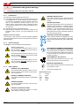 6
6
-
 7
7
-
 8
8
-
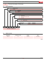 9
9
-
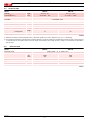 10
10
-
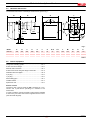 11
11
-
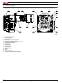 12
12
-
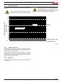 13
13
-
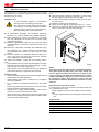 14
14
-
 15
15
-
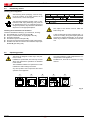 16
16
-
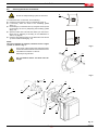 17
17
-
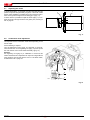 18
18
-
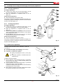 19
19
-
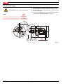 20
20
-
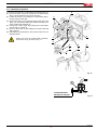 21
21
-
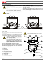 22
22
-
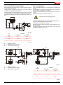 23
23
-
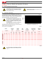 24
24
-
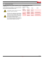 25
25
-
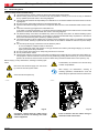 26
26
-
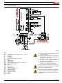 27
27
-
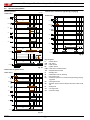 28
28
-
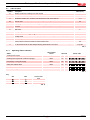 29
29
-
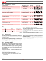 30
30
-
 31
31
-
 32
32
-
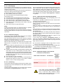 33
33
-
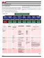 34
34
-
 35
35
-
 36
36
-
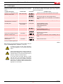 37
37
-
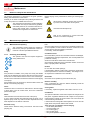 38
38
-
 39
39
-
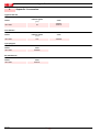 40
40
-
 41
41
-
 42
42
-
 43
43
-
 44
44
-
 45
45
-
 46
46
-
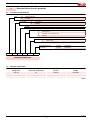 47
47
-
 48
48
-
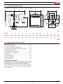 49
49
-
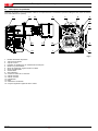 50
50
-
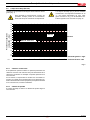 51
51
-
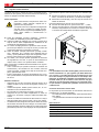 52
52
-
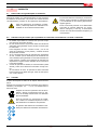 53
53
-
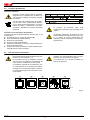 54
54
-
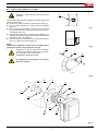 55
55
-
 56
56
-
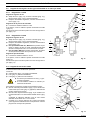 57
57
-
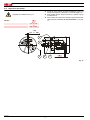 58
58
-
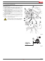 59
59
-
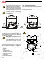 60
60
-
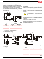 61
61
-
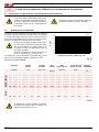 62
62
-
 63
63
-
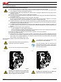 64
64
-
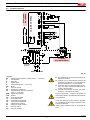 65
65
-
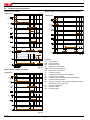 66
66
-
 67
67
-
 68
68
-
 69
69
-
 70
70
-
 71
71
-
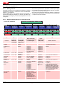 72
72
-
 73
73
-
 74
74
-
 75
75
-
 76
76
-
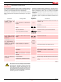 77
77
-
 78
78
-
 79
79
-
 80
80


Riello BG6.1D TL 1/230/50 Installer Manual
- Tipo
- Installer Manual
- Este manual también es adecuado para
en otros idiomas
- English: Riello BG6.1D TL 1/230/50
Otros documentos
-
BALTUR TBL 130P DACA Manual User Instructions
-
 ECOFLAM MAX GAS 500 PR Operating Instructions Manual
-
Sime 1R HE 9 ErP Manual de usuario
-
Lamborghini ECO PRO 20/2 Installation and Maintenance Manual
-
-
-
-
Ferroli Pegasus Manual de usuario
-
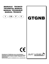 SANT ANDREA GTGNB El manual del propietario
-
Hauck WHI Instrucciones de operación

