
English
Cautions
Run all ground (earth) leads to a common ground
(earth) point.
This unit is designed for negative ground (earth) 12 V
DC operation only.
Do not disassemble or modify the unit.
Do not install in locations which interfere with airbag
operation.
Do not get the leads under a screw, or caught in
moving parts (e.g. seat railing).
Before making connections, turn the car ignition off
to avoid short circuits.
Connect the yellow and red power supply leads
only after all other leads have been connected.
Be sure to insulate any loose unconnected leads
with electrical tape for safety.
Do not press on the LCD when installing the unit.
Install the unit with the monitor facing straight
forward; do not install it at a slanted angle.
Notes on the power supply lead (yellow)
When connecting this unit in combination with other
stereo components, the amperage rating of the car
circuit to which the unit is connected must be higher
than the sum of each component's fuse amperage
rating.
If no car circuits are rated high enough, connect the
unit directly to the battery.
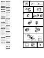
Parts list
The bracket is attached to the unit before shipping.
Before mounting the unit, use the release keys to
remove the bracket from the unit. For details, see
“Removing the bracket ()” on the reverse side of the
sheet.
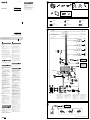
Connection diagram
To a common ground (earth) point
First connect the black ground (earth) lead, then connect the
yellow and red power supply leads.
To the power antenna (aerial) control lead or
the power supply lead of the antenna (aerial)
booster
Notes
It is not necessary to connect this lead if there is no power
antenna (aerial) or antenna (aerial) booster, or with a
manually-operated telescopic antenna (aerial).
If your car has a built-in FM/AM antenna (aerial) in the rear/
side glass, see “Notes on the control and power supply leads.”
To AMP REMOTE IN of an optional power
amplifier
This connection is only for amplifiers. Connecting any other
system may damage the unit.
To a car’s illumination signal
Be sure to first connect the black ground (earth) lead to a
common ground (earth) point.
To the +12 V power terminal which is
energized when the ignition switch is set to
the accessory position
Notes
If there is no accessory position, connect to the +12 V power
(battery) terminal which is energized at all times.
Be sure to first connect the black ground (earth) lead to a
common ground (earth) point.
If your car has a built-in FM/AM antenna (aerial) in the rear/
side glass, see “Notes on the control and power supply leads.”
To the +12 V power terminal which is
energized at all times
Be sure to first connect the black ground (earth) lead to a
common ground (earth) point.
To the parking brake switch cord
The mounting position of the parking brake switch cord depends
on your car. For details, see “Connecting the parking brake lead
()” on the reverse side.
To an auxiliary device such as a portable
media player, game console, etc. (not
supplied)
Tip
You can use an RCA pin cord (not supplied) to connect auxiliary
devices.
To the +12 V power terminal of the car’s rear
lamp lead (only when connecting the rear
view camera)
Notes on the control and power supply leads
REM OUT lead (blue/white striped) supplies +12 V DC when you turn
on the unit.
If your car has built-in FM/AM antenna (aerial) in the rear/side
glass, connect REM OUT lead (blue/white striped) or the accessory
power supply lead (red) to the power terminal of the existing
antenna (aerial) booster. For details, consult your dealer.
A power antenna (aerial) without a relay box cannot be used with
this unit.
Memory hold connection
When the yellow power supply lead is connected, power will always
be supplied to the memory circuit even when the ignition switch is
turned off.
Notes on speaker connection
Before connecting the speakers, turn the unit off.
Use speakers with an impedance of 4 to 8 ohms, and with
adequate power handling capacities to avoid damage.
Do not connect the speaker terminals to the car chassis, or connect
the terminals of the right speakers with those of the left speakers.
Do not connect the ground (earth) lead of this unit to the negative
(–) terminal of a speaker.
Do not attempt to connect the speakers in parallel.
Connect only passive speakers. Connecting active speakers (with
built-in amplifiers) to the speaker terminals may damage the unit.
To avoid a malfunction, do not use the built-in speaker leads
installed in your car if they feature a common negative (–) lead for
the right and left speakers.
Do not connect the unit’s speaker leads to each other.
Notes on connection
If [Check Audio Output Wiring] appears in the display, make sure
the speaker and amplifier are connected correctly.
To use the monitor for the rear seats, connect the parking brake
switch cord to the ground (earth).
Securing the connection of the
HDMI/MHL connection cable
(XAV-712BT/612BT only)
Secure the connection between the HDMI/MHL
connection cable and main unit, using the hook and
loop fastener .
1 Wrap the hook and loop fastener around the
neck of a cable.
2 Pull the hook and loop fastener firmly back
around the neck of the other cable.
3 Bring the ends of the hook and loop fastener
together to secure the connection of the cables.
Español
Precauciones
Conecte todos los cables de conexión a masa a un
punto común.
Esta unidad ha sido diseñada para alimentarse
solamente con cc de 12 V de masa negativa.
No desmonte ni modifique la unidad.
No instale la unidad en lugares en los que interfiera
con el funcionamiento del airbag.
No coloque los cables debajo de ningún tornillo, ni
los aprisione con partes móviles (p. ej. los raíles del
asiento).
Antes de realizar las conexiones, desactive el
encendido del automóvil para evitar cortocircuitos.
Conecte los cables de fuente de alimentación
amarillo y rojo solamente después de haber
conectado los demás.
Por razones de seguridad, asegúrese de aislar con
cinta aislante los cables sueltos que no estén
conectados.
No presione la pantalla LCD cuando instale la
unidad.
Al instalar la unidad, el monitor debe mirar hacia
adelante; no la instale en un ángulo inclinado.
Notas sobre el cable de fuente de alimentación
(amarillo)
Cuando conecte esta unidad en combinación con
otros componentes estéreo, la capacidad nominal
del circuito conectado del automóvil debe ser
superior a la suma del fusible de cada componente.
Si no hay circuitos del automóvil con capacidad
nominal suficientemente alta, conecte la unidad
directamente a la batería.
Lista de componentes
El soporte se coloca en la unidad antes de ser
transportada. Antes de montarla, utilice las llaves de
liberación para extraer el soporte . Para obtener
más información, consulte “Extracción del soporte
()” en el reverso de esta página.
Diagrama de conexiones
A un punto de conexión a masa común
Conecte primero el cable de conexión a masa negro, y después
los cables de fuente de alimentación rojo y amarillo.
Al cable de control de la antena motorizada o
al cable de fuente de alimentación del
amplificador de señal de la antena
Notas
Si no se dispone de antena motorizada ni de amplificador de
señal de la antena, o se utiliza una antena telescópica
accionada manualmente, no será necesario conectar este
cable.
Si el automóvil tiene una antena FM/AM integrada en el cristal
posterior o lateral, consulte las “Notas sobre los cables de
control y de fuente de alimentación”.
A AMP REMOTE IN de un amplificador de
potencia opcional
Esta conexión es sólo para amplificadores. La conexión de
cualquier otro sistema puede dañar la unidad.
A una señal de iluminación del automóvil
Asegúrese de conectar primero el cable de conexión a masa
negro a un punto de conexión a masa común.
Al terminal de alimentación de +12 V que
recibe energía cuando el interruptor de la
llave de encendido se coloca en la posición
de accesorio
Notas
Si no hay posición de accesorio, conéctelo al terminal de
alimentación (batería) de +12 V que recibe energía sin
interrupción.
Asegúrese de conectar primero el cable de conexión a masa
negro a un punto de conexión a masa común.
Si el automóvil tiene una antena FM/AM integrada en el cristal
posterior o lateral, consulte las “Notas sobre los cables de
control y de fuente de alimentación”.
Al terminal de alimentación de +12 V que
recibe energía sin interrupción
Asegúrese de conectar primero el cable de conexión a masa
negro a un punto de conexión a masa común.
Al cable de conmutación del freno de
estacionamiento
La posición de montaje del cable de conmutación del freno de
estacionamiento depende del automóvil. Para obtener detalles,
vea la sección “Conexión del cable del freno de estacionamiento
()” del lado reverso.
A un dispositivo auxiliar, como, por ejemplo,
un reproductor portátil, una consola de
videojuegos, etc. (no suministrados)
Sugerencia
Es posible utilizar el cable con terminales RCA (no suministrado)
para conectar dispositivos auxiliares.
Al terminal de alimentación de +12 V del
cable del indicador posterior del automóvil
(únicamente cuando conecte la cámara
retrovisora)
Notas sobre los cables de control y de fuente de alimentación
El cable REM OUT (rayado azul y blanco) suministra cc +12 V al
encender la unidad.
Si el automóvil dispone de una antena de FM/AM incorporada en el
cristal trasero o lateral, conecte el cable REM OUT (rayado azul y
blanco) o el cable de fuente de alimentación auxiliar (rojo) al
terminal de alimentación del amplificador de señal de la antena
existente. Para obtener más detalles, consulte a su distribuidor.
Con esta unidad no es posible utilizar una antena motorizada sin
caja de relé.
Conexión para protección de la memoria
Si conecta el cable de fuente de alimentación amarillo, el circuito de
la memoria recibirá siempre alimentación, aunque apague el
interruptor de encendido.
Notas sobre la conexión de los altavoces
Antes de conectar los altavoces, desconecte la alimentación de la
unidad.
Utilice altavoces con una impedancia de 4 a 8 Ω con la capacidad
de potencia adecuada para evitar que se dañen.
No conecte los terminales de altavoz al chasis del automóvil ni
conecte los terminales de altavoz derecho con los del izquierdo.
No conecte el cable de conexión a masa de esta unidad al terminal
negativo (–) del altavoz.
No intente conectar los altavoces en paralelo.
Conecte solamente altavoces pasivos. Si conecta altavoces activos
(con amplificadores incorporados) a los terminales de altavoz,
puede dañar la unidad.
Para evitar fallas de funcionamiento, no utilice los cables de altavoz
integrados instalados en el automóvil si la unidad comparte un
cable negativo común (–) para los altavoces derecho e izquierdo.
No conecte los cables de altavoz de la unidad entre sí.
Notas sobre la conexión
Si en la pantalla aparece [Verifique el cableado de salida audio],
verifique que el altavoz y el amplificador estén conectados
correctamente.
Si va a utilizar el monitor para los asientos posteriores, conecte el
cable de conmutación del freno de estacionamiento a masa.
*
1
Para obtener detalles sobre la instalación del
micrófono, consulte “Instalación del micrófono
()” al reverso.
*
2
Cable con terminales RCA (no suministrado)
*
3
Cable de conexión HDMI o MHL (suministrados)
(solo XAV-712BT/612BT)
*
4
El sonido se emitirá a través de este terminal
sólo cuando esté activado ZONE × ZONE. Este
terminal emite a un nivel fijo
independientemente del control de volumen
de la unidad.
*
5
Puede requerirse un adaptador independiente.
*
6
Se recomienda utilizar el cable posterior de
USB denominado “HIGH CHARGE” para
recargar la batería de un dispositivo
conectado.
*
7
Para conectar un teléfono inteligente a la
unidad principal, es necesario utilizar un cable
adecuado (no suministrado).
*
8
El cable USB posterior sin la etiqueta “HIGH
CHARGE” (solo XAV-712BT)
*
9
Entrada HDMI/MHL en el puerto (solo
XAV-712BT/612BT)
*
10
Impedancia del altavoz: 4 – 8 Ω × 4
*
1
For details on installing the microphone, see
“Installing the microphone ()” on the reverse
side.
*
2
RCA pin cord (not supplied)
*
3
HDMI connection cable or MHL connection
cable (supplied) (XAV-712BT/612BT only)
*
4
The sound is output from this terminal only
when ZONE × ZONE is activated. This terminal
outputs a fixed level regardless of the volume
control of the unit.
*
5
A separate adaptor may be required.
*
6
The USB rear cable labeled “HIGH CHARGE” is
recommended to use for recharging the
battery of a connected device.
*
7
To connect a smartphone to the main unit, an
appropriate cable (not supplied) is required.
*
8
The USB rear cable without “HIGH CHARGE”
label (XAV-712BT only)
*
9
The HDMI in/MHL in port (XAV-712BT/612BT
only)
*
10
Speaker impedance: 4 – 8 ohms × 4
Equipment used in illustrations (not supplied) / Equipo utilizado en las ilustraciones (no suministrado)
Subwoofer
Altavoz potenciador de graves
Rear speaker
Altavoz posterior
Rear view camera
Cámara retrovisora
Monitor
Monitor
Power amplifier
Amplificador de potencia
Front speaker
Altavoz frontal
× 2
XAV-712BT/612BT only / solo XAV-712BT/612BT
× 6
b
a
Fuse (10 A)
Fusible (10 A)
HIGH CHARGE
From car antenna (aerial)
Desde la antena del automóvil
*
2
REM OUT
Max. supply current: 0.4 A
Corriente máx. de alimentación: 0,4 A
ILLUMINATION
Left
Izquierdo
Right
Derecho
Left
Izquierdo
Right
Derecho
Blue/white striped
Con rayas azules/blancas
White
Blanco
Green
Verde
Purple
Morado
White/black striped
Con rayas blancas/negras
Gray/black striped
Con rayas grises/negras
Green/black striped
Con rayas verdes/negras
Gray
Gris
Purple/black striped
Con rayas moradas/negras
Black
Negro
Orange/white striped
Con rayas naranjas/blancas
PARKING BRAKE
Red
Rojo
Yellow
Amarillo
Light green
Verde claro
*
1
*
2
*
6
*
8
*
9
*
3
*
3
*
2
*
2
Smartphone
Teléfono inteligente
Smartphone*
7
, USB device
Teléfono inteligente*
7
,
dispositivo USB
*
2
*
2
GND ACC
BATTERY
or / o
*
10
XAV-712BT/612BT only / solo XAV-712BT/612BT
*
1
HDMI connection cable or MHL connection cable (supplied) (XAV-712BT/612BT only)
*
1
Cable de conexión HDMI o MHL (suministrados) (solo XAV-712BT/612BT)
*
1
*
1
or
/ o
Smartphone
Teléfono inteligente
Asegurar la conexión del cable de
conexión HDMI/MHL (solo
XAV-712BT/612BT)
Asegure la conexión entre el cable de conexión HDMI/
MHL y la unidad principal mediante el cierre de
gancho y lazo .
1 Envuelva el cierre de gancho y lazo alrededor
del cuello de un cable.
2 Tire del cierre de gancho y lazo hacia atrás con
firmeza para envolverlo alrededor del otro cable.
3 Una los extremos del cierre de gancho y lazo
para asegurar la conexión de los cables.
XAV-712BT/XAV-612BT/XAV-602BT
4-476-911-62(1)
©2013 Sony Corporation Printed in Thailand
AV Center
Installation/Connections
GB
Instalación/Conexiones
ES

Español
Precauciones
Elija cuidadosamente el lugar de montaje de forma
que la unidad no interfiera con las funciones
normales de conducción.
Evite instalar la unidad donde pueda quedar
sometida a polvo, suciedad, vibraciones excesivas o
altas temperaturas como, por ejemplo, a la luz solar
directa o cerca de conductos de calefacción.
Para realizar una instalación segura y firme, utilice
solamente elementos de instalación suministrados.
Para mover el panel frontal con suavidad, insertar/
extraer discos fácilmente y, sobre todo, para
conducir con seguridad, es necesario mantener una
distancia adecuada entre el panel frontal y la
palanca de cambios. La distancia necesaria varía en
función de la posición de la palanca de cambios de
su automóvil. Antes de instalar la unidad, elija
cuidadosamente el lugar de instalación para que
pueda conducir con seguridad. (Para XAV-712BT, ver
la fig. .)
Ajuste del ángulo de montaje
Ajuste el ángulo de montaje a menos de 45°.
Acerca de las ilustraciones
XAV-602BT es el modelo que se utiliza para las
ilustraciones, a menos que se indique lo contrario.
Conexión del cable del freno de
estacionamiento
Asegúrese de conectar el cable del freno de
estacionamiento (verde claro) del cable de conexión
de la fuente de alimentación al cable de
conmutación del freno de estacionamiento.
Instalación del micrófono
Para capturar la voz durante llamadas con manos
libres, debe instalar el micrófono .
Precauciones
Mantenga el micrófono alejado de lugares con
humedad y temperaturas muy altas.
Que el cable se enrolle alrededor del volante o de la
palanca de cambios es extremadamente peligroso.
Asegúrese de impedir que el cable y otros
componentes obstruyan la conducción.
Si el vehículo dispone de airbags u otros dispositivos
de amortiguación de impactos, póngase en contacto
con el establecimiento donde ha adquirido esta
unidad o con el concesionario de automóviles antes
de llevar a cabo la instalación.
Notas
Antes de colocar la cinta adhesiva de doble cara
b
, limpie la
superficie del tablero con un paño seco.
Ajuste el ángulo del micrófono en la posición adecuada.
Forma de extraer e instalar el
panel frontal (solo XAV-
612BT/602BT)
Antes de instalar la unidad, extraiga el panel
frontal.
-A Para extraerlo
Antes de extraer el panel frontal, mantenga
presionado OFF durante más de 2 segundos para
desactivar la unidad. Presione
, y luego mantenga
apretado el lado izquierdo del panel frontal y tire
hacia la derecha para abrirlo.
Consejo
Si también levanta ligeramente el lado izquierdo del panel frontal ,
el panel frontal saldrá fácilmente.
-B Para instalarlo
Coloque los orificios del panel frontal en las clavijas
de la unidad, luego presione suavemente el lado
izquierdo.
Extracción del soporte
Antes de instalar la unidad, extraiga el soporte
de la unidad.
Conserve las llaves de liberación para utilizarlas
en el futuro, ya que también las necesitará si retira
la unidad del automóvil.
Precaución
Tenga mucho cuidado al manipular el soporte para
evitar posibles lesiones en los dedos.
1 Inserte las llaves de liberación en los
enganches entre la unidad y el soporte al
mismo tiempo hasta que encajen.
2 Presione el soporte y, a continuación, levante
la unidad para separar ambos elementos.
Nota
La forma del marco y la ubicación de los enganches pueden ser
diferentes según el modelo.
Montaje de la unidad
-A Montaje de la unidad con el soporte
suministrado
1 Antes de instalar la unidad, compruebe que los
enganches de ambos lados del soporte estén
doblados hacia adentro 3,5 mm.
2 Coloque el soporte suministrado dentro del
salpicadero.
3 Doble los ganchos hacia fuera para conseguir
una fijación segura.
4 Monte la unidad en el soporte suministrado .
Nota
Si los enganches están derechos o doblados hacia afuera, la unidad
no se instalará correctamente y puede desprenderse.
-B Montaje de la unidad en un
automóvil japonés
Es posible que pueda instalar la unidad en algunos
automóviles japoneses sin el soporte suministrado. En
caso de que no pudiera, consulte al distribuidor Sony
más cercano.
Cuando monte la unidad en los soportes
preinstalados de su automóvil, utilice los tornillos
suministrados en los orificios para tornillos
correspondientes en función de su automóvil: T para
TOYOTA, M para MITSUBISHI y N para NISSAN.
Notas
Para evitar que se produzcan fallas de funcionamiento, realice la
instalación solamente con los tornillos suministrados .
No ejerza excesiva fuerza sobre los botones de la unidad.
No presione la pantalla LCD.
Asegúrese de que no haya ningún objeto encima de la unidad
antes de montarla.
Advertencia: si el encendido del
automóvil no dispone de una
posición ACC
Asegúrese de ajustar la función Auto DESACTIVAR.
Para obtener más información, consulte el “Manual de
instrucciones” suministrado.
La unidad se apagará completa y automáticamente en
el tiempo establecido si no se selecciona ninguna
fuente, lo cual evita que se desgaste la batería.
Si no ha ajustado la función Auto DESACTIVAR,
mantenga presionado OFF cada vez que apague el
interruptor de encendido, hasta que la pantalla
desaparezca.
Botón de reinicio
Una vez finalizadas la instalación y las conexiones,
asegúrese de presionar el botón de reinicio, que está
ubicado detrás del panel frontal, con un bolígrafo, etc.
Sustitución del fusible
Al sustituir el fusible, asegúrese de utilizar uno cuyo
amperaje coincida con el especificado en el original. Si
el fusible se funde, verifique la conexión de
alimentación y sustitúyalo. Si el fusible vuelve a
fundirse después de sustituirlo, es posible que exista
alguna falla de funcionamiento interno. En tal caso,
consulte con el distribuidor Sony más cercano.
English
Precautions
Choose the installation location carefully so that the
unit will not interfere with normal driving operations.
Avoid installing the unit in areas subject to dust, dirt,
excessive vibration, or high temperature, such as in
direct sunlight or near heater ducts.
Use only the supplied mounting hardware for a safe
and secure installation.
To move the front panel smoothly, to insert/eject a
disc easily, and especially to drive safely, keep an
adequate distance between the front panel and the
shift lever. The necessary distance differs, depending
on the shift lever position of your car. Before
installing the unit, choose the installation location
carefully so that you can drive safely. (For XAV-712BT,
see fig. .)
Mounting angle adjustment
Adjust the mounting angle to less than 45°.
About illustrations
XAV-602BT is the model used for illustration purposes,
unless otherwise noted.
Connecting the parking brake
lead
Be sure to connect the parking brake lead (light green)
of the power supply connection cable to the
parking brake switch cord.
Installing the microphone
To capture your voice during handsfree calling, you
need to install the microphone .
Cautions
Keep the microphone away from extremely high
temperatures and humidity.
It is extremely dangerous if the cord becomes
wound around the steering column or gearstick. Be
sure to keep it and other parts from obstructing your
driving.
If airbags or any other shock-absorbing equipment
is in your car, contact the store where you purchased
this unit, or the car dealer, before installation.
Notes
Before attaching the double-sided tape
b
, clean the surface of the
dashboard with a dry cloth.
Adjust the microphone angle to the proper position.
How to detach and attach the
front panel (XAV-612BT/602BT
only)
Before installing the unit, detach the front panel.
-A To detach
Before detaching the front panel, press and hold OFF
for more than 2 seconds to turn off the unit. Press
,
and then hold the left side of the front panel and pull
it open to the right.
Tip
If you also lift the left side of the front panel slightly , the front
panel comes out easily.
-B To attach
Place the recesses of the front panel onto the pegs
on the unit, then lightly push the left side in.
Removing the bracket
Before installing the unit, remove the bracket
from the unit.
Keep the release keys for future use as they are
also necessary if you remove the unit from your car.
Caution
Handle the bracket carefully to avoid injuring your
fingers.
1 Insert the release keys into the catches
between the unit and the bracket at the same
time until they click.
2 Pull down the bracket , then pull up the unit to
separate them.
Note
The form of the frame and location of the catch may differ depending
on the model.
Mounting the unit
-A Mounting the unit with the supplied
bracket
1 Before installing, make sure that the catches on
both sides of the bracket are bent inwards 3.5
mm (
5
/32 in).
2 Position the supplied bracket inside the
dashboard.
3 Bend the claws outward for a tight fit.
4 Mount the unit onto the supplied bracket .
Note
If the catches are straight or bent outwards, the unit will not be
installed securely and may spring out.
-B Mounting the unit in a Japanese car
You may be able to install this unit in some makes of
Japanese cars without the supplied bracket. If you
cannot, consult your Sony dealer.
When mounting this unit to the preinstalled brackets
of your car, use the supplied screws in the
appropriate screw holes, based on your car: T for
TOYOTA, M for MITSUBISHI and N for NISSAN.
Notes
To avoid a malfunction, install only with the supplied screws .
Do not apply excessive force to the buttons of the unit.
Do not press on the LCD.
Before mounting, make sure there is nothing on the top of the unit.
Warning if your car’s ignition has
no ACC position
Be sure to set the Auto OFF function. For details, refer
to the supplied “Operating Instructions.”
The unit will shut off completely and automatically in
the set time when no source is selected, which
prevents battery drainage.
If the Auto OFF function has not been set, press and
hold OFF until the display disappears each time you
turn the ignition off.
Reset button
When the installation and connections are completed,
be sure to press the reset button, which is located
behind the front panel, with a ballpoint pen, etc.
Fuse replacement
When replacing the fuse, be sure to use one matching
the amperage rating stated on the original fuse. If the
fuse blows, check the power connection and replace
the fuse. If the fuse blows again after replacement,
there may be an internal malfunction. In such a case,
consult your nearest Sony dealer.
B
To the dashboard/center console
Al tablero o consola central
Bracket
Soporte
Parts supplied with your car
Partes suministradas con el automóvil
Size:
5 × max. 8 mm
(
7
/32 × max.
5
/16 in)
Tamaño:
5 × 8 mm máx.
Size:
5 × max. 8 mm
(
7
/32 × max.
5
/16 in)
Tamaño:
5 × 8 mm máx.
Bracket
Soporte
Location of screw holes
Ubicación de los orificios para los tornillos
T: TOYOTA
M: MITSUBISHI
N: NISSAN
XAV-712BT XAV-612BT/602BT
Fuse (10 A)
Fusible (10 A)
a
Clips (not supplied)
Clips (no suministrados)
Parking brake switch cord
Cable de conmutación del freno de estacionamiento
Foot brake type
Tipo de freno de pedal
Parking brake switch cord
Cable de conmutación del freno de estacionamiento
Hand brake type
Tipo de freno manual
Shift lever
Palanca de cambios
87 mm (3 1/2 in)
87 mm
A B
XAV-612BT/602BT only / solo XAV-612BT/602BT
XAV-712BT only/ solo XAV-712BT
Face the hook inwards.
El gancho debe encontrarse
en la parte interior.
Catch
Enganche
Installing on the sun visor / Instalación en la visera Installing on the dashboard / Instalación en el salpicadero
A
Dashboard
Tablero
Claws
Uñas
Larger than 182 mm (7
1
/4 in)
Superior a 182 mm
Catch
Enganche
Larger than 111 mm (4
3
/8 in)
Superior a 111 mm
a
Clip (not supplied)
Clip (no suministrado)
b
Transcripción de documentos
4-476-911-62(1) Asegurar la conexión del cable de conexión HDMI/MHL (solo XAV-712BT/612BT) XAV-712BT/612BT only / solo XAV-712BT/612BT Asegure la conexión entre el cable de conexión HDMI/ MHL y la unidad principal mediante el cierre de gancho y lazo . 1 Envuelva el cierre de gancho y lazo alrededor ×2 del cuello de un cable. AV Center Installation/Connections Instalación/Conexiones 2 Tire del cierre de gancho y lazo hacia atrás con GB ES firmeza para envolverlo alrededor del otro cable. 3 Una los extremos del cierre de gancho y lazo para asegurar la conexión de los cables. b a ×6 Equipment used in illustrations (not supplied) / Equipo utilizado en las ilustraciones (no suministrado) Front speaker Altavoz frontal Rear speaker Altavoz posterior Rear view camera Cámara retrovisora Power amplifier Amplificador de potencia Subwoofer Altavoz potenciador de graves Monitor Monitor Black Negro GND Blue/white striped Con rayas azules/blancas REM OUT Red Rojo ACC Yellow Amarillo BATTERY Max. supply current: 0.4 A Corriente máx. de alimentación: 0,4 A ©2013 Sony Corporation Printed in Thailand Orange/white striped Con rayas naranjas/blancas ILLUMINATION Light green Verde claro PARKING BRAKE XAV-712BT/XAV-612BT/XAV-602BT White Blanco English Español Cautions Precauciones ˎˎRun all ground (earth) leads to a common ground (earth) point. ˎˎThis unit is designed for negative ground (earth) 12 V DC operation only. ˎˎDo not disassemble or modify the unit. ˎˎDo not install in locations which interfere with airbag operation. ˎˎDo not get the leads under a screw, or caught in moving parts (e.g. seat railing). ˎˎBefore making connections, turn the car ignition off to avoid short circuits. ˎˎConnect the yellow and red power supply leads only after all other leads have been connected. ˎˎBe sure to insulate any loose unconnected leads with electrical tape for safety. ˎˎDo not press on the LCD when installing the unit. ˎˎInstall the unit with the monitor facing straight forward; do not install it at a slanted angle. Notes on the power supply lead (yellow) ˎˎWhen connecting this unit in combination with other stereo components, the amperage rating of the car circuit to which the unit is connected must be higher than the sum of each component's fuse amperage rating. ˎˎIf no car circuits are rated high enough, connect the unit directly to the battery. Parts list The bracket is attached to the unit before shipping. Before mounting the unit, use the release keys to remove the bracket from the unit. For details, see “Removing the bracket ()” on the reverse side of the sheet. Connection diagram To a common ground (earth) point First connect the black ground (earth) lead, then connect the yellow and red power supply leads. To the power antenna (aerial) control lead or the power supply lead of the antenna (aerial) booster Notes ˎˎIt is not necessary to connect this lead if there is no power antenna (aerial) or antenna (aerial) booster, or with a manually-operated telescopic antenna (aerial). ˎˎIf your car has a built-in FM/AM antenna (aerial) in the rear/ side glass, see “Notes on the control and power supply leads.” To AMP REMOTE IN of an optional power amplifier Be sure to first connect the black ground (earth) lead to a common ground (earth) point. To the parking brake switch cord The mounting position of the parking brake switch cord depends on your car. For details, see “Connecting the parking brake lead ()” on the reverse side. To an auxiliary device such as a portable media player, game console, etc. (not supplied) Tip You can use an RCA pin cord (not supplied) to connect auxiliary devices. To the +12 V power terminal of the car’s rear lamp lead (only when connecting the rear view camera) Notes on the control and power supply leads ˎˎREM OUT lead (blue/white striped) supplies +12 V DC when you turn on the unit. ˎˎIf your car has built-in FM/AM antenna (aerial) in the rear/side glass, connect REM OUT lead (blue/white striped) or the accessory power supply lead (red) to the power terminal of the existing antenna (aerial) booster. For details, consult your dealer. ˎˎA power antenna (aerial) without a relay box cannot be used with this unit. Memory hold connection When the yellow power supply lead is connected, power will always be supplied to the memory circuit even when the ignition switch is turned off. Notes on speaker connection ˎˎBefore connecting the speakers, turn the unit off. ˎˎUse speakers with an impedance of 4 to 8 ohms, and with adequate power handling capacities to avoid damage. ˎˎDo not connect the speaker terminals to the car chassis, or connect the terminals of the right speakers with those of the left speakers. ˎˎDo not connect the ground (earth) lead of this unit to the negative (–) terminal of a speaker. ˎˎDo not attempt to connect the speakers in parallel. ˎˎConnect only passive speakers. Connecting active speakers (with built-in amplifiers) to the speaker terminals may damage the unit. ˎˎTo avoid a malfunction, do not use the built-in speaker leads installed in your car if they feature a common negative (–) lead for the right and left speakers. ˎˎDo not connect the unit’s speaker leads to each other. Notes on connection ˎˎIf [Check Audio Output Wiring] appears in the display, make sure the speaker and amplifier are connected correctly. ˎˎTo use the monitor for the rear seats, connect the parking brake switch cord to the ground (earth). Securing the connection of the HDMI/MHL connection cable (XAV-712BT/612BT only) Secure the connection between the HDMI/MHL connection cable and main unit, using the hook and loop fastener . 1 Wrap the hook and loop fastener around the neck of a cable. 2 Pull the hook and loop fastener firmly back around the neck of the other cable. 3 Bring the ends of the hook and loop fastener together to secure the connection of the cables. Right Derecho *10 Green Verde Green/black striped Con rayas verdes/negras Left Izquierdo Purple Morado *2 Purple/black striped Con rayas moradas/negras Right Derecho Smartphone Teléfono inteligente or *3 / o *3 *9 Lista de componentes El soporte se coloca en la unidad antes de ser transportada. Antes de montarla, utilice las llaves de liberación para extraer el soporte . Para obtener más información, consulte “Extracción del soporte ()” en el reverso de esta página. Smartphone*7, USB device Teléfono inteligente*7, dispositivo USB *8 HIGH CHARGE *6 Diagrama de conexiones A un punto de conexión a masa común Conecte primero el cable de conexión a masa negro, y después los cables de fuente de alimentación rojo y amarillo. Al cable de control de la antena motorizada o al cable de fuente de alimentación del amplificador de señal de la antena Be sure to first connect the black ground (earth) lead to a common ground (earth) point. To the +12 V power terminal which is energized at all times Gray/black striped Con rayas grises/negras Notas sobre el cable de fuente de alimentación (amarillo) ˎˎCuando conecte esta unidad en combinación con otros componentes estéreo, la capacidad nominal del circuito conectado del automóvil debe ser superior a la suma del fusible de cada componente. ˎˎSi no hay circuitos del automóvil con capacidad nominal suficientemente alta, conecte la unidad directamente a la batería. To a car’s illumination signal Notes ˎˎIf there is no accessory position, connect to the +12 V power (battery) terminal which is energized at all times. Be sure to first connect the black ground (earth) lead to a common ground (earth) point. ˎˎIf your car has a built-in FM/AM antenna (aerial) in the rear/ side glass, see “Notes on the control and power supply leads.” Left Izquierdo Gray Gris ˎˎConecte todos los cables de conexión a masa a un punto común. ˎˎEsta unidad ha sido diseñada para alimentarse solamente con cc de 12 V de masa negativa. ˎˎNo desmonte ni modifique la unidad. ˎˎNo instale la unidad en lugares en los que interfiera con el funcionamiento del airbag. ˎˎNo coloque los cables debajo de ningún tornillo, ni los aprisione con partes móviles (p. ej. los raíles del asiento). ˎˎAntes de realizar las conexiones, desactive el encendido del automóvil para evitar cortocircuitos. ˎˎConecte los cables de fuente de alimentación amarillo y rojo solamente después de haber conectado los demás. ˎˎPor razones de seguridad, asegúrese de aislar con cinta aislante los cables sueltos que no estén conectados. ˎˎNo presione la pantalla LCD cuando instale la unidad. ˎˎAl instalar la unidad, el monitor debe mirar hacia adelante; no la instale en un ángulo inclinado. This connection is only for amplifiers. Connecting any other system may damage the unit. To the +12 V power terminal which is energized when the ignition switch is set to the accessory position White/black striped Con rayas blancas/negras From car antenna (aerial) Desde la antena del automóvil *2 Notas ˎˎSi no se dispone de antena motorizada ni de amplificador de señal de la antena, o se utiliza una antena telescópica accionada manualmente, no será necesario conectar este cable. ˎˎSi el automóvil tiene una antena FM/AM integrada en el cristal posterior o lateral, consulte las “Notas sobre los cables de control y de fuente de alimentación”. Fuse (10 A) Fusible (10 A) A AMP REMOTE IN de un amplificador de potencia opcional Esta conexión es sólo para amplificadores. La conexión de cualquier otro sistema puede dañar la unidad. A una señal de iluminación del automóvil *1 Asegúrese de conectar primero el cable de conexión a masa negro a un punto de conexión a masa común. Al terminal de alimentación de +12 V que recibe energía cuando el interruptor de la llave de encendido se coloca en la posición de accesorio *2 Notas ˎˎSi no hay posición de accesorio, conéctelo al terminal de alimentación (batería) de +12 V que recibe energía sin interrupción. Asegúrese de conectar primero el cable de conexión a masa negro a un punto de conexión a masa común. ˎˎSi el automóvil tiene una antena FM/AM integrada en el cristal posterior o lateral, consulte las “Notas sobre los cables de control y de fuente de alimentación”. Al terminal de alimentación de +12 V que recibe energía sin interrupción Asegúrese de conectar primero el cable de conexión a masa negro a un punto de conexión a masa común. Al cable de conmutación del freno de estacionamiento *2 La posición de montaje del cable de conmutación del freno de estacionamiento depende del automóvil. Para obtener detalles, vea la sección “Conexión del cable del freno de estacionamiento ()” del lado reverso. *2 A un dispositivo auxiliar, como, por ejemplo, un reproductor portátil, una consola de videojuegos, etc. (no suministrados) *2 Sugerencia Es posible utilizar el cable con terminales RCA (no suministrado) para conectar dispositivos auxiliares. Al terminal de alimentación de +12 V del cable del indicador posterior del automóvil (únicamente cuando conecte la cámara retrovisora) *1 For details on installing the microphone, see “Installing the microphone ()” on the reverse side. *2 RCA pin cord (not supplied) *3 HDMI connection cable or MHL connection cable (supplied) (XAV-712BT/612BT only) *4 The sound is output from this terminal only when ZONE × ZONE is activated. This terminal outputs a fixed level regardless of the volume control of the unit. 5 * A separate adaptor may be required. Notas sobre los cables de control y de fuente de alimentación ˎˎEl cable REM OUT (rayado azul y blanco) suministra cc +12 V al encender la unidad. ˎˎSi el automóvil dispone de una antena de FM/AM incorporada en el cristal trasero o lateral, conecte el cable REM OUT (rayado azul y blanco) o el cable de fuente de alimentación auxiliar (rojo) al terminal de alimentación del amplificador de señal de la antena existente. Para obtener más detalles, consulte a su distribuidor. ˎˎCon esta unidad no es posible utilizar una antena motorizada sin caja de relé. *6 The USB rear cable labeled “HIGH CHARGE” is recommended to use for recharging the battery of a connected device. *7 To connect a smartphone to the main unit, an appropriate cable (not supplied) is required. *8 The USB rear cable without “HIGH CHARGE” label (XAV-712BT only) *9 The HDMI in/MHL in port (XAV-712BT/612BT only) *10 Speaker impedance: 4 – 8 ohms × 4 *1 Para obtener detalles sobre la instalación del micrófono, consulte “Instalación del micrófono ()” al reverso. *2 Cable con terminales RCA (no suministrado) *3 Cable de conexión HDMI o MHL (suministrados) (solo XAV-712BT/612BT) *4 El sonido se emitirá a través de este terminal sólo cuando esté activado ZONE × ZONE. Este terminal emite a un nivel fijo independientemente del control de volumen de la unidad. *5 Puede requerirse un adaptador independiente. *6 Se recomienda utilizar el cable posterior de USB denominado “HIGH CHARGE” para recargar la batería de un dispositivo conectado. *7 Para conectar un teléfono inteligente a la unidad principal, es necesario utilizar un cable adecuado (no suministrado). *8 El cable USB posterior sin la etiqueta “HIGH CHARGE” (solo XAV-712BT) *9 Entrada HDMI/MHL en el puerto (solo XAV-712BT/612BT) *10 Impedancia del altavoz: 4 – 8 Ω × 4 Conexión para protección de la memoria Si conecta el cable de fuente de alimentación amarillo, el circuito de la memoria recibirá siempre alimentación, aunque apague el interruptor de encendido. Notas sobre la conexión de los altavoces ˎˎAntes de conectar los altavoces, desconecte la alimentación de la unidad. ˎˎUtilice altavoces con una impedancia de 4 a 8 Ω con la capacidad de potencia adecuada para evitar que se dañen. ˎˎNo conecte los terminales de altavoz al chasis del automóvil ni conecte los terminales de altavoz derecho con los del izquierdo. ˎˎNo conecte el cable de conexión a masa de esta unidad al terminal negativo (–) del altavoz. ˎˎNo intente conectar los altavoces en paralelo. ˎˎConecte solamente altavoces pasivos. Si conecta altavoces activos (con amplificadores incorporados) a los terminales de altavoz, puede dañar la unidad. ˎˎPara evitar fallas de funcionamiento, no utilice los cables de altavoz integrados instalados en el automóvil si la unidad comparte un cable negativo común (–) para los altavoces derecho e izquierdo. ˎˎNo conecte los cables de altavoz de la unidad entre sí. Notas sobre la conexión ˎˎSi en la pantalla aparece [Verifique el cableado de salida audio], verifique que el altavoz y el amplificador estén conectados correctamente. ˎˎSi va a utilizar el monitor para los asientos posteriores, conecte el cable de conmutación del freno de estacionamiento a masa. XAV-712BT/612BT only / solo XAV-712BT/612BT Smartphone Teléfono inteligente or *1 / o *1 *1 HDMI connection cable or MHL connection cable (supplied) (XAV-712BT/612BT only) *1 Cable de conexión HDMI o MHL (suministrados) (solo XAV-712BT/612BT) English Español Precautions Precauciones ˎˎChoose the installation location carefully so that the unit will not interfere with normal driving operations. ˎˎAvoid installing the unit in areas subject to dust, dirt, excessive vibration, or high temperature, such as in direct sunlight or near heater ducts. ˎˎUse only the supplied mounting hardware for a safe and secure installation. ˎˎTo move the front panel smoothly, to insert/eject a disc easily, and especially to drive safely, keep an adequate distance between the front panel and the shift lever. The necessary distance differs, depending on the shift lever position of your car. Before installing the unit, choose the installation location carefully so that you can drive safely. (For XAV-712BT, see fig. .) Adjust the mounting angle to less than 45°. ˎˎElija cuidadosamente el lugar de montaje de forma que la unidad no interfiera con las funciones normales de conducción. ˎˎEvite instalar la unidad donde pueda quedar sometida a polvo, suciedad, vibraciones excesivas o altas temperaturas como, por ejemplo, a la luz solar directa o cerca de conductos de calefacción. ˎˎPara realizar una instalación segura y firme, utilice solamente elementos de instalación suministrados. ˎˎPara mover el panel frontal con suavidad, insertar/ extraer discos fácilmente y, sobre todo, para conducir con seguridad, es necesario mantener una distancia adecuada entre el panel frontal y la palanca de cambios. La distancia necesaria varía en función de la posición de la palanca de cambios de su automóvil. Antes de instalar la unidad, elija cuidadosamente el lugar de instalación para que pueda conducir con seguridad. (Para XAV-712BT, ver la fig. .) About illustrations Ajuste del ángulo de montaje XAV-602BT is the model used for illustration purposes, unless otherwise noted. Ajuste el ángulo de montaje a menos de 45°. Mounting angle adjustment Connecting the parking brake lead Be sure to connect the parking brake lead (light green) of the power supply connection cable to the parking brake switch cord. Installing the microphone To capture your voice during handsfree calling, you need to install the microphone . Cautions ˎˎKeep the microphone away from extremely high temperatures and humidity. ˎˎIt is extremely dangerous if the cord becomes wound around the steering column or gearstick. Be sure to keep it and other parts from obstructing your driving. ˎˎIf airbags or any other shock-absorbing equipment is in your car, contact the store where you purchased this unit, or the car dealer, before installation. Notes ˎˎBefore attaching the double-sided tape b , clean the surface of the dashboard with a dry cloth. ˎˎAdjust the microphone angle to the proper position. How to detach and attach the front panel (XAV-612BT/602BT only) Before installing the unit, detach the front panel. -A To detach Before detaching the front panel, press and hold OFF for more than 2 seconds to turn off the unit. Press , and then hold the left side of the front panel and pull it open to the right. Tip If you also lift the left side of the front panel slightly , the front panel comes out easily. -B To attach Place the recesses of the front panel onto the pegs on the unit, then lightly push the left side in. Removing the bracket Before installing the unit, remove the bracket from the unit. Keep the release keys for future use as they are also necessary if you remove the unit from your car. Caution Handle the bracket carefully to avoid injuring your fingers. 1 Insert the release keys into the catches between the unit and the bracket at the same time until they click. 2 Pull down the bracket , then pull up the unit to separate them. Note The form of the frame and location of the catch may differ depending on the model. Mounting the unit -A Mounting the unit with the supplied bracket 1 Before installing, make sure that the catches on both sides of the bracket are bent inwards 3.5 mm (5/32 in). 2 Position the supplied bracket inside the XAV-712BT only/ solo XAV-712BT Hand brake type Tipo de freno manual Foot brake type Tipo de freno de pedal 87 mm (3 1/2 in) 87 mm Shift lever Palanca de cambios Parking brake switch cord Cable de conmutación del freno de estacionamiento Parking brake switch cord Cable de conmutación del freno de estacionamiento Installing on the sun visor / Instalación en la visera Installing on the dashboard / Instalación en el salpicadero a a Acerca de las ilustraciones XAV-602BT es el modelo que se utiliza para las ilustraciones, a menos que se indique lo contrario. Conexión del cable del freno de estacionamiento Clip (not supplied) Clip (no suministrado) b Asegúrese de conectar el cable del freno de estacionamiento (verde claro) del cable de conexión de la fuente de alimentación al cable de conmutación del freno de estacionamiento. Clips (not supplied) Clips (no suministrados) Instalación del micrófono Para capturar la voz durante llamadas con manos libres, debe instalar el micrófono . Precauciones ˎˎMantenga el micrófono alejado de lugares con humedad y temperaturas muy altas. ˎˎQue el cable se enrolle alrededor del volante o de la palanca de cambios es extremadamente peligroso. Asegúrese de impedir que el cable y otros componentes obstruyan la conducción. ˎˎSi el vehículo dispone de airbags u otros dispositivos de amortiguación de impactos, póngase en contacto con el establecimiento donde ha adquirido esta unidad o con el concesionario de automóviles antes de llevar a cabo la instalación. XAV-612BT/602BT only / solo XAV-612BT/602BT A B Notas ˎˎAntes de colocar la cinta adhesiva de doble cara b , limpie la superficie del tablero con un paño seco. ˎˎAjuste el ángulo del micrófono en la posición adecuada. Forma de extraer e instalar el panel frontal (solo XAV612BT/602BT) Antes de instalar la unidad, extraiga el panel frontal. -A Para extraerlo Antes de extraer el panel frontal, mantenga presionado OFF durante más de 2 segundos para desactivar la unidad. Presione , y luego mantenga apretado el lado izquierdo del panel frontal y tire hacia la derecha para abrirlo. Face the hook inwards. El gancho debe encontrarse en la parte interior. Consejo Si también levanta ligeramente el lado izquierdo del panel frontal , el panel frontal saldrá fácilmente. Catch Enganche -B Para instalarlo Coloque los orificios del panel frontal en las clavijas de la unidad, luego presione suavemente el lado izquierdo. Extracción del soporte Antes de instalar la unidad, extraiga el soporte de la unidad. Conserve las llaves de liberación para utilizarlas en el futuro, ya que también las necesitará si retira la unidad del automóvil. Precaución Tenga mucho cuidado al manipular el soporte para evitar posibles lesiones en los dedos. A Larger than 182 mm (7 1/4 in) Superior a 182 mm 1 Inserte las llaves de liberación en los enganches entre la unidad y el soporte al mismo tiempo hasta que encajen. 2 Presione el soporte y, a continuación, levante Larger than 111 mm (4 3/8 in) Superior a 111 mm la unidad para separar ambos elementos. Nota La forma del marco y la ubicación de los enganches pueden ser diferentes según el modelo. Dashboard Tablero dashboard. 3 Bend the claws outward for a tight fit. 4 Mount the unit onto the supplied bracket . Note If the catches are straight or bent outwards, the unit will not be installed securely and may spring out. -B Mounting the unit in a Japanese car You may be able to install this unit in some makes of Japanese cars without the supplied bracket. If you cannot, consult your Sony dealer. When mounting this unit to the preinstalled brackets of your car, use the supplied screws in the appropriate screw holes, based on your car: T for TOYOTA, M for MITSUBISHI and N for NISSAN. Notes ˎˎTo avoid a malfunction, install only with the supplied screws . ˎˎDo not apply excessive force to the buttons of the unit. ˎˎDo not press on the LCD. ˎˎBefore mounting, make sure there is nothing on the top of the unit. Warning if your car’s ignition has no ACC position Be sure to set the Auto OFF function. For details, refer to the supplied “Operating Instructions.” The unit will shut off completely and automatically in the set time when no source is selected, which prevents battery drainage. If the Auto OFF function has not been set, press and hold OFF until the display disappears each time you turn the ignition off. Reset button When the installation and connections are completed, be sure to press the reset button, which is located behind the front panel, with a ballpoint pen, etc. Fuse replacement When replacing the fuse, be sure to use one matching the amperage rating stated on the original fuse. If the fuse blows, check the power connection and replace the fuse. If the fuse blows again after replacement, there may be an internal malfunction. In such a case, consult your nearest Sony dealer. Montaje de la unidad Claws Uñas Catch Enganche -A Montaje de la unidad con el soporte suministrado 1 Antes de instalar la unidad, compruebe que los enganches de ambos lados del soporte estén doblados hacia adentro 3,5 mm. 2 Coloque el soporte suministrado dentro del salpicadero. 3 Doble los ganchos hacia fuera para conseguir B Size: 5 × max. 8 mm (7/32 × max. 5/ 16 in) Tamaño: 5 × 8 mm máx. una fijación segura. 4 Monte la unidad en el soporte suministrado . Nota Si los enganches están derechos o doblados hacia afuera, la unidad no se instalará correctamente y puede desprenderse. To the dashboard/center console Al tablero o consola central -B Montaje de la unidad en un automóvil japonés Es posible que pueda instalar la unidad en algunos automóviles japoneses sin el soporte suministrado. En caso de que no pudiera, consulte al distribuidor Sony más cercano. Bracket Soporte Cuando monte la unidad en los soportes preinstalados de su automóvil, utilice los tornillos suministrados en los orificios para tornillos correspondientes en función de su automóvil: T para TOYOTA, M para MITSUBISHI y N para NISSAN. Asegúrese de ajustar la función Auto DESACTIVAR. Para obtener más información, consulte el “Manual de instrucciones” suministrado. La unidad se apagará completa y automáticamente en el tiempo establecido si no se selecciona ninguna fuente, lo cual evita que se desgaste la batería. Si no ha ajustado la función Auto DESACTIVAR, mantenga presionado OFF cada vez que apague el interruptor de encendido, hasta que la pantalla desaparezca. Botón de reinicio Una vez finalizadas la instalación y las conexiones, asegúrese de presionar el botón de reinicio, que está ubicado detrás del panel frontal, con un bolígrafo, etc. Sustitución del fusible Al sustituir el fusible, asegúrese de utilizar uno cuyo amperaje coincida con el especificado en el original. Si el fusible se funde, verifique la conexión de alimentación y sustitúyalo. Si el fusible vuelve a fundirse después de sustituirlo, es posible que exista alguna falla de funcionamiento interno. En tal caso, consulte con el distribuidor Sony más cercano. Parts supplied with your car Partes suministradas con el automóvil Notas ˎˎPara evitar que se produzcan fallas de funcionamiento, realice la instalación solamente con los tornillos suministrados . ˎˎNo ejerza excesiva fuerza sobre los botones de la unidad. ˎˎNo presione la pantalla LCD. ˎˎAsegúrese de que no haya ningún objeto encima de la unidad antes de montarla. Advertencia: si el encendido del automóvil no dispone de una posición ACC Location of screw holes Ubicación de los orificios para los tornillos T: TOYOTA M: MITSUBISHI N: NISSAN Bracket Soporte XAV-712BT XAV-612BT/602BT Size: 5 × max. 8 mm (7/32 × max. 5/16 in) Tamaño: 5 × 8 mm máx. Fuse (10 A) Fusible (10 A)-
 1
1
-
 2
2


Sony XAV-602BT Guía de inicio rápido
- Tipo
- Guía de inicio rápido
en otros idiomas
- English: Sony XAV-602BT Quick start guide
Artículos relacionados
-
Sony XAV-602BT Guía de instalación
-
Sony WX-GT90BT Guía de instalación
-
Sony MEX-DV900 Guía de instalación
-
-
Sony XAV-63 Guía de instalación
-
Sony XAV-65 Guía de instalación
-
Sony XAV-68BT Guía de instalación
-
-
-