
SONY MEX-DV900 (GB,ES,CS) 3-283-927-31 (1)SONY MEX-DV900 (GB,ES,CS) 3-283-927-31 (1)
注意
• 本机只能使用负极接地的 12 V 直流电源。
• 勿使电线夹在螺钉下,或缠在移动部件上(如座椅扶
手)。
• 连接线路之前,请关闭汽车点火开关,以避免短路。
• 只有连接了所有其他导线之后,再连接黄色和红色电源
线。
• 将所有地线都连接到同一接地点。
• 为了安全,请务必用绝缘胶带使所有松散未连接的电线
绝缘。
关于电源线(黄色)的注意事项
• 将本机与其它立体声装置组合使用时,所连接的汽车电
路容量必须大于各装置保险丝容量的总和。
• 当汽车电路容量不够大时,请将本机直接与蓄电池相连
接。
零件一览表
• 表中数字与说明书中的数字是一致的。
• 装卸支架 和保护环 是运输之前装在本机上的。
安装本机之前,使用开锁钥匙 从本机上取下装卸
支架 和保护环 。详细内容,请参阅本页反面
的“拆卸保护环和装卸支架 ()”。
• 保存好开锁钥匙 以备后用。您从汽车上取下本装置
时,有必要用到该钥匙。
注意
小心使用装卸支架
以免伤到手指。
固定片
注
安装前,请确认装卸支架 两边的固定片向内弯曲 2 mm。如果固定片
笔直或向外弯曲,本机将不能牢固安装并可能弹出。
线路连接图例
注 (-B)
• 务必在连接放大器之前连接接地线。
• 只有在使用内置的放大器时,警报才会发出声响。
线路连接图
至汽车金属表面
首先连接黑色接地导线,然后连接黄色和红色电源线。
至电动天线控制导线或天线升缩器的电源导线
注
• 如果没有电动天线或天线升缩器,或有手动伸缩式天线,则无需
连接此导线。
• 若汽车的后/侧玻璃内有内置 FM/AM 天线,请参阅“关于控制导
线和电源导线的注意事项”。
至选购的功率放大器的 AMP REMOTE IN
此连接仅适用于功率放大器。连接其它系统可能损坏本机。
至 +12 V 电源端子,该端子在点火开关附件位置通电
注
• 如果没有附件位置,则连接至 +12 V 电源(蓄电池)端子,该端
子随时处于通电状态。
确保首先将黑色接地导线连接至汽车金属表面。
• 若汽车的后/侧玻璃内有内置 FM/AM 天线,请参阅“关于控制导
线和电源导线的注意事项”。
至 +12 V 电源端子,该端子随时处于通电状态
确保首先将黑色接地导线连接至汽车金属表面。
至停车制动开关电线
关于控制导线和电源导线的注意事项
• 接通调谐器电源时,电动天线的控制导线(蓝色)便能提供 +12 V 直
流电。
• 当汽车的后/侧玻璃窗内有内置 FM/AM 天线时,请将电动天线控制线
(蓝色)或附件电源线(红色)连接至现有天线升缩器上的电源端子
上。详细说明,请与您的经销商联系。
• 本机不能使用不具备继电器盒的电动天线。
保持记忆的线路连接法
当连接了黄色的电源线时,即使点火开关关闭,电源仍将对记忆电路
供电。
关于扬声器连接的注意事项
• 连接扬声器之前,请关闭本机电源。
• 请使用阻抗为 4-8 Ω 且具有足够功率处理能力的扬声器,以免损
坏。
• 勿将扬声器端子连接到汽车底盘上,或将右扬声器的端子与左扬声器
的端子连接。
• 勿将本机的接地线连接到扬声器的负极(-)端子上。
• 扬声器不可并联连接。
• 请仅连接无源扬声器。将有源扬声器(具有内置放大器)连接到扬声
器端子可能会损坏本机。
• 若本机使用左、右扬声器的共用负极(-)电线,为了避免故障,切勿
使用安装在汽车内的内置扬声器电线。
• 请勿将本机扬声器电线相互连接。
连接的注意事项
• 如果未正确连接扬声器和放大器,则显示屏上会出现“FAILURE”。这
时,请确保扬声器和放大器连接正确。
• 如果您要使用后座监视器,则将停车制动开关电线连接至接地。
L
R
AU
X
IN
VIDEO
OUT
AUX IN
REAR AUDIO OUT
VIDEO OUT
Installation/Connections
Instalación/Conexiones
安装/线路连接
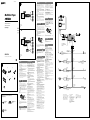
Connection diagram
To a metal surface of the car
First connect the black ground (earth) lead, then connect the
yellow and red power supply leads.
To the power antenna (aerial) control lead or
power supply lead of antenna (aerial) booster
Notes
• It is not necessary to connect this lead if there is no power
antenna (aerial) or antenna (aerial) booster, or with a
manually-operated telescopic antenna (aerial).
• When your car has a built-in FM/AM antenna (aerial) in the
rear/side glass, see “Notes on the control and power supply
leads.”
To AMP REMOTE IN of an optional power
amplifier
This connection is only for amplifiers. Connecting any other
system may damage the unit.
To the +12 V power terminal which is
energized in the accessory position of the
ignition switch
Notes
• If there is no accessory position, connect to the +12 V
power (battery) terminal which is energized at all times.
Be sure to connect the black ground (earth) lead to a metal
surface of the car first.
• When your car has a built-in FM/AM antenna (aerial) in the
rear/side glass, see “Notes on the control and power supply
leads.”
To the +12 V power terminal which is
energized at all times
Be sure to connect the black ground (earth) lead to a metal
surface of the car first.
To the parking brake switch cord
Notes on the control and power supply leads
• The power antenna (aerial) control lead (blue) supplies +12 V
DC when you turn on the tuner.
• When your car has built-in FM/AM antenna (aerial) in the
rear/side glass, connect the power antenna (aerial) control lead
(blue) or the accessory power supply lead (red) to the power
terminal of the existing antenna (aerial) booster. For details,
consult your dealer.
• A power antenna (aerial) without a relay box cannot be used
with this unit.
Memory hold connection
When the yellow power supply lead is connected, power will
always be supplied to the memory circuit even when the ignition
switch is turned off.
Notes on speaker connection
• Before connecting the speakers, turn the unit off.
• Use speakers with an impedance of 4 to 8 ohms, and with
adequate power handling capacities to avoid its damage.
• Do not connect the speaker terminals to the car chassis, or
connect the terminals of the right speakers with those of the left
speaker.
• Do not connect the ground (earth) lead of this unit to the
negative (–) terminal of the speaker.
• Do not attempt to connect the speakers in parallel.
• Connect only passive speakers. Connecting active speakers
(with built-in amplifiers) to the speaker terminals may damage
the unit.
• To avoid a malfunction, do not use the built-in speaker leads
installed in your car if the unit shares a common negative (–)
lead for the right and left speakers.
• Do not connect the unit’s speaker leads to each other.
Notes on connection
• If speaker and amplifier are not connected correctly, “FAILURE”
appears in the display. In this case, make sure the speaker and
amplifier are connected correctly.
• If you are to use the monitor for the rear seats, connect the
parking brake switch cord to the ground (earth).
A
B
Equipment used in illustrations (not supplied)
Equipo utilizado en las ilustraciones (no suministrado)
插图中的装置(非附送)
from car antenna (aerial)
desde la antena del automóvil
来自汽车天线
Rear speaker
Altavoz posterior
后置扬声器
Front speaker
Altavoz frontal
前置扬声器
Power amplifier
Amplificador de potencia
功率放大器
Cautions
• This unit is designed for negative ground (earth) 12 V
DC operation only.
• Do not get the leads under a screw, or caught in moving
parts (e.g. seat railing).
• Before making connections, turn the car ignition off to
avoid short circuits.
• Connect the yellow
and red power supply leads only
after all other leads have been connected.
• Run all ground (earth) leads to a common
ground (earth) point.
• Be sure to insulate any loose unconnected leads with
electrical tape for safety.
Notes on the power supply lead (yellow)
• When connecting this unit in combination with other
stereo components, the connected car circuit’s rating
must be higher than the sum of each component’s fuse.
• When no car circuits are rated high enough, connect
the unit directly to the battery.
Parts list
• The numbers in the list are keyed to those in the
instructions.
• The bracket
and the protection collar are
attached to the unit before shipping. Before mounting
the unit, use the release keys
to remove the bracket
and the protection collar from the unit. For
details, see “Removing the protection collar and the
bracket (
)” on the reverse side of the sheet.
• Keep the release keys for future use as they
are also necessary if you remove the unit from
your car.
Caution
Handle the bracket
carefully to avoid injuring your
fingers.
Note
Before installing, make sure that the catches on both sides of
the bracket
are bent inwards 2 mm (
3
/32 in). If the catches are
straight or bent outwards, the unit will not be installed securely
and may spring out.
Connection example
Notes (-
B
)
• Be sure to connect the ground (earth) lead before connecting
the amplifier.
• The alarm will only sound if the built-in amplifier is used.
Catch
× 4
× 2
AMP REM
Max. supply current 0.3 A
Corriente máx. de alimentación de 0,3 A
最大电流 0.3 A
Fuse (10 A)
Fusible (10 A)
保险丝 (10 A)
Blue/white striped
Con rayas azules y blancas
蓝色/白色条纹
Red
Rojo
红色
Yellow
Amarillo
黄色
White
Blanco
白色
Green
Verde
绿色
Purple
Morado
紫色
White/black striped
Con rayas blancas y negras
白色/黑色条纹
Gray/black striped
Con rayas grises y negras
灰色/黑色条纹
Green/black striped
Con rayas verdes y negras
绿色/黑色条纹
Gray
Gris
灰色
Left
Izquierdo
左
Right
Derecho
右
Left
Izquierdo
左
Right
Derecho
右
ANT REM
Black
Negro
黑色
Blue
Azul
蓝色
Max. supply current 0.1 A
Corriente máx. de alimentación de 0,1 A
最大电流 0.1 A
Purple/black striped
Con rayas moradas y negras
紫色/黑色条纹
*
1
*
2
3-283-927-31 (1)
Multi Disc Player
MEX-DV900
©
2008 Sony Corporation Printed in Thailand
VIDEO OUT
Monitor*
Monitor*
监视器*
REAR AUDIO OUT
VIDEO OUT
Monitor*
Monitor*
监视器*
* not supplied
no suministrado
非附送
* not supplied
no suministrado
非附送
Monitor (not supplied)
Monitor (no suministrado)
监视器 (非附送)
Light green
Verde claro
淡绿色
*
1
RCA pin cord (not supplied)
*
2
For details on connecting to the parking
brake switch cord, see “Connecting the
parking brake cord
()” on the reverse
side.
*
3
Auxiliary device such as hideaway
navigation device, TV tuner box, etc.
*
1
Cable con terminales RCA
(no suministrado)
*
2
Para obtener detalles acerca de cómo
conectar el cable de conmutación del
freno de estacionamiento, consulte
“Conexión del cable del freno de
estacionamiento ()” en el dorso.
*
3
Dispositivo auxiliar como, por
ejemplo, un dispositivo de navegación
independiente, un sintonizador de
televisión, etc.
*
1
RCA针导线(非附送)
*
2
有关连接至停车制动开关导线的详细说
明,请参阅反面的“连接停车制动电线
()”。
*
3
例如隐藏式导航设备、TV调谐盒等辅助
设备。
Precauciones
• Esta unidad ha sido diseñada para alimentarse sólo con cc de
12 V de masa negativa.
• No coloque los cables debajo de ningún tornillo, ni los
aprisione con partes móviles (p. ej. los raíles del asiento).
• Antes de realizar las conexiones, desactive el encendido del
automóvil para evitar cortocircuitos.
• Conecte los cables de fuente de alimentación
amarillo y
rojo
solamente después de haber conectado los demás.
• Conecte todos los cables de conexión a masa a un
punto común.
• Por razones de seguridad, asegúrese de aislar con cinta
aislante los cables sueltos que no estén conectados.
Notas sobre el cable de fuente de alimentación
(amarillo)
• Cuando conecte esta unidad en combinación con otros
componentes estéreo, la capacidad nominal del circuito
conectado del automóvil debe ser superior a la suma del
fusible de cada componente.
• Si no hay circuitos del automóvil con capacidad nominal
suficientemente alta, conecte la unidad directamente a la
batería.
Lista de componentes
• Los números de la lista corresponden a los de las
instrucciones.
• La unidad se comercializa con el soporte
y el marco de
protección ya colocados. Antes de montarla, utilice las
llaves de liberación
para extraer el soporte y el marco
de protección
de la misma. Para obtener más información,
consulte “Extracción del marco de protección y del soporte
()”.
• Conserve las llaves de liberación para utilizarlas
en el futuro, ya que también las necesitará si retira
la unidad del automóvil.
Precaución
Tenga mucho cuidado al manipular el soporte
para evitar
posibles lesiones en los dedos.
Enganche
Nota
Antes de instalar la unidad, compruebe que los enganches de
ambos lados del soporte
están doblados hacia adentro 2 mm. Si
no lo están o están doblados hacia afuera, la unidad no se instalará
correctamente y puede saltar.
Ejemplo de conexiones
Notas (-
B
)
• Asegúrese de conectar primero el cable de conexión a masa antes
de realizar la conexión del amplificador.
• La alarma sonará únicamente si se utiliza el amplificador
incorporado.
Diagrama de conexiones
A una superficie metálica del automóvil
Conecte primero el cable de conexión a masa negro, y después los
cables amarillo y rojo de fuente de alimentación.
Al cable de control de la antena motorizada o al
cable de fuente de alimentación del amplificador
de señal de la antena
Notas
• Si no se dispone de antena motorizada ni de amplificador
de antena, o se utiliza una antena telescópica accionada
manualmente, no será necesario conectar este cable.
• Si el automóvil incorpora una antena de FM/AM en el cristal
posterior o lateral, consulte “Notas sobre los cables de control y
de fuente de alimentación”.
A AMP REMOTE IN de un amplificador de
potencia opcional
Esta conexión es sólo para amplificadores. La conexión de
cualquier otro sistema puede dañar la unidad.
Al terminal de alimentación de +12 V que
recibe energía en la posición de accesorio del
interruptor de la llave de encendido
Notas
• Si no hay posición de accesorio, conéctelo al terminal de
alimentación (batería) de +12 V que recibe energía sin
interrupción.
Asegúrese de conectar primero el cable de conexión a masa
negro a una superficie metálica del automóvil.
• Si el automóvil incorpora una antena de FM/AM en el cristal
posterior o lateral, consulte “Notas sobre los cables de control y
de fuente de alimentación”.
Al terminal de alimentación de +12 V que recibe
energía sin interrupción
Asegúrese de conectar primero el cable de conexión a masa negro
a una superficie metálica del automóvil.
Al cable de conmutación del freno de
estacionamiento
Notas sobre los cables de control y de fuente de alimentación
• El cable de control de la antena motorizada (azul) suministrará cc de
+ 12 V cuando conecte la alimentación del sintonizador.
• Si el automóvil dispone de una antena de FM/AM incorporada en
el cristal posterior o lateral, conecte el cable de control de antena
motorizada (azul) o el cable de fuente de alimentación auxiliar (rojo)
al terminal de alimentación del amplificador de antena existente. Para
obtener más información, consulte a su distribuidor.
• Con esta unidad no es posible utilizar una antena motorizada sin
caja de relé.
Conexión para protección de la memoria
Si conecta el cable de fuente de alimentación amarillo, el circuito de la
memoria recibirá siempre alimentación, aunque apague el interruptor
de encendido.
Notas sobre la conexión de los altavoces
• Antes de conectar los altavoces, desconecte la alimentación de la
unidad.
• Utilice altavoces con una impedancia de 4 a 8 Ω con la capacidad de
potencia adecuada para evitar que se dañen.
• No conecte los terminales de altavoz al chasis del automóvil, ni
conecte los terminales del altavoz derecho con los del izquierdo.
• No conecte el cable de conexión a masa de esta unidad al terminal
negativo (–) del altavoz.
• No intente conectar los altavoces en paralelo.
• Conecte solamente altavoces pasivos. Si conecta altavoces activos
(con amplificadores incorporados) a los terminales de altavoz, puede
dañar la unidad.
• Para evitar fallas de funcionamiento, no utilice los cables de altavoz
incorporados instalados en el automóvil si la unidad comparte un
cable negativo común (–) para los altavoces derecho e izquierdo.
• No conecte los cables de altavoz de la unidad entre sí.
Notas sobre la conexión
• Si el altavoz y el amplificador no están conectados correctamente,
aparecerá “FAILURE” en la pantalla. Si es así, compruebe la
conexión de ambos dispositivos.
• Si va a utilizar el monitor para los asientos posteriores, conecte el
cable de conmutación del freno de estacionamiento a masa.
PARKING BRAKE
*
3

SONY MEX-DV900 (GB,ES,CS) 3-283-927-31 (1)SONY MEX-DV900 (GB,ES,CS) 3-283-927-31 (1)
1
2 3
182 mm
53 mm
Dashboard
Tablero
仪表板
A TOYOTA
to dashboard/center console
al tablero o consola central
至仪表板/中央控制箱
Bracket
Soporte
托架
Bracket
Soporte
托架
B NISSAN
to dashboard/center console
al tablero o consola central
至仪表板/中央控制箱
Bracket
Soporte
托架
Bracket
Soporte
托架
Existing parts supplied with your car
Piezas existentes suministradas con su automóvil
随汽车附送的现有部件
A
B
1
2
max. size
5 × 8 mm
(
7
/32 ×
11
/32 in)
Tamaño máx.
5 × 8 mm
最大尺寸
5×8 mm
max. size
5 × 8 mm
(
7
/32 ×
11
/32 in)
Tamaño máx.
5 × 8 mm
最大尺寸
5×8 mm
max. size
5 × 8 mm
(
7
/32 ×
11
/32 in)
Tamaño máx.
5 × 8 mm
最大尺寸
5×8 mm
max. size
5 × 8 mm
(
7
/32 ×
11
/32 in)
Tamaño máx.
5 × 8 mm
最大尺寸
5×8 mm
Face the hook
inwards.
El gancho debe
encontrarse en la
parte interior.
钩子面向内。
Claws
Uñas
卡爪
Warning if your car’s ignition
has no ACC position
Be sure to set the Auto Off function. For details, see the
supplied Operating Instructions.
The unit will shut off completely and automatically in
the set time after the unit is turned off, which prevents
battery drain.
If you do not set the Auto Off function, press and hold
until the display disappears each time you turn
the ignition off.
RESET button
When the installation and connections are completed,
be sure to press the RESET button with a ball-point pen,
etc., after detaching the front panel.
Precautions
• Choose the installation location carefully so that the
unit will not interfere with normal driving operations.
• Avoid installing the unit in areas subject to dust, dirt,
excessive vibration, or high temperatures, such as in
direct sunlight or near heater ducts.
• Use only the supplied mounting hardware for a safe
and secure installation.
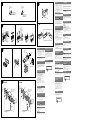
Mounting angle adjustment
Adjust the mounting angle to less than 45°.
Connecting the parking brake
cord
Be sure to connect the parking cord (Light green) of
to the parking brake switch cord. The mounting position
of the parking brake switch cord depends on your car.
Consult your car dealer or your nearest Sony dealer for
further details.
Removing the protection collar
and the bracket
Before installing the unit, remove the protection
collar and the bracket from the unit.
1 Remove the protection collar .
Engage the release keys together with the
protection collar .
Pull out the release keys to remove the
protection collar .
2 Remove the bracket .
Insert both release keys together between
the unit and the bracket until they click.
Pull down the bracket , then pull up the unit
to separate.
Mounting example
Installation in the dashboard
Notes
• Bend these claws outward for a tight fit, if necessary (-
2
).
• Make sure that the 4 catches on the protection collar are
properly engaged in the slots of the unit
(-
3
).
Mounting the unit in a Japanese
car
You may not be able to install this unit in some makes of
Japanese cars. In such a case, consult your Sony dealer.
Note
To prevent malfunction, install only with the supplied screws
.
How to detach and attach the
front panel
Before installing the unit, detach the front panel.
-A To detach
Before detaching the front panel, be sure to press .
Press , and pull it off towards you.
-B To attach
Engage part of the front panel with part of the unit,
as illustrated, and push the left side into position until it
clicks.
Precauciones
• Elija cuidadosamente el lugar de montaje de forma que
la unidad no interfiera con las funciones normales de
conducción.
• Evite instalar la unidad donde pueda quedar sometida
a polvo, suciedad, vibraciones excesivas o altas
temperaturas como, por ejemplo, a la luz solar directa o
cerca de conductos de calefacción.
• Para realizar una instalación segura y firme, utilice
solamente elementos de instalación suministrados.
Ajuste del ángulo de montaje
Ajuste el ángulo de montaje a menos de 45°.
Conexión del cable del freno de
estacionamiento
Asegúrese de conectar el cable del freno (verde claro) de
al cable de conmutación del freno de estacionamiento.
La posición de montaje del cable de conmutación
del freno de estacionamiento depende del automóvil.
Consulte al distribuidor del automóvil o al distribuidor
Sony más cercano para obtener más detalles.
Extracción del marco de
protección y del soporte
Antes de instalar la unidad, retire el marco de
protección
y el soporte de la misma.
1 Retire el marco de protección .
Acople las llaves de liberación al marco de
protección .
Retire las llaves de liberación para extraer
el marco de protección .
2 Retire el soporte .
Inserte ambas llaves de liberación entre la
unidad y el soporte hasta que encajen.
Presione el soporte y, a continuación,
levante la unidad para separar ambos
elementos.
Ejemplo de montaje
Instalación en el tablero
Notas
• Si es necesario, doble estos ganchos hacia fuera para que
encaje firmemente
(-
2
).
• Compruebe que los 4 enganches del marco de protección
estén bien fijados en las ranuras de la unidad
(-
3
).
Montaje de la unidad en un
automóvil japonés
Es posible que no pueda instalar esta unidad en algunos
automóviles japoneses. En tal caso, consulte a su
distribuidor Sony.
Nota
Para evitar que se produzcan fallas de funcionamiento, realice la
instalación solamente con los tornillos suministrados
.
Forma de extraer e instalar el
panel frontal
Antes de instalar la unidad, extraiga el panel
frontal.
-A Para extraerlo
Antes de extraer el panel frontal, asegúrese de presionar
. Después presione y tire de él hacia usted.
-B Para instalarlo
Coloque la parte del panel frontal en la parte de
la unidad, como se muestra en la ilustración, y después
presione la parte izquierda hasta que encaje.
Advertencia: si el encendido del
automóvil no dispone de una
posición ACC
Asegúrese de ajustar la función de desconexión
automática. Para obtener más información, consulte el
manual de instrucciones suministrado.
La unidad se apagará completa y automáticamente en
el tiempo establecido después de que se desconecte la
unidad, lo que evita que se desgaste la batería.
Si no ha ajustado la función de desconexión automática,
mantenga presionado
cada vez que apague
el interruptor de encendido, hasta que la pantalla
desaparezca.
Botón RESET
Una vez finalizada la instalación y las conexiones,
desmonte el panel frontal y presione el botón RESET con
un bolígrafo o un objeto similar.
Orient the release key
correctly.
Oriente la llave de
liberación en la
dirección correcta.
正确确定开锁钥匙方向。
Existing parts supplied with your car
Piezas existentes suministradas con su automóvil
随汽车附送的现有部件
Fire wall
Cortafuegos
防火壁
使用前注意事项
• 仔细选取安装位置,以使本机不干扰正常的驾驶操
作。
• 避免将本机安装在受灰尘、污物和强烈振动影响的
区域,或安装在高温处,如直射阳光下或热气管道
附近。
• 为了安装安全和可靠,只能使用附送的安装构件。
安装角度之调整
请在 45°以内调整安装角度。
连接停车制动电线
必须将 的停车电线(淡绿色)与停车制动开关
电线连接。停车制动开关电线的安装位置视您的汽车
而定。更详细信息,请联系您的汽车经销商或附近的
Sony 经销商。
拆卸保护环和装卸支架
安装本装置之前,请先从本机上取下保护环 和
装卸支架 。
1 拆卸保护环 。
衔接开锁钥匙 和保护环 。
拉出开锁钥匙 以取下保护环 。
2 拆卸装卸支架
。
将 2 个开锁钥匙 插入本机和装卸支架
之间直到听见喀嗒声。
向下拉装卸支架
,然后向上拉出本机以
便分离。
安装示例
安装在仪表板里
注
• 如有必要,向外弯曲卡爪以紧固安装(-2)。
• 请确保保护环 上的 4 个固定片与本机的卡槽正确衔接
(-3)。
将本机安装于日本产汽车上
有的日本产汽车不能安装本机。在这种情形下,请向
Sony 经销商咨询。
注
为防止发生故障,安装时只能使用附送的螺丝 。
如何拆卸和装配前面板
安装本机之前,请先拆卸前面板。
-A 拆卸
拆卸前面板前,须按
。按 ,然后将前面板
向您身体方向拉出。
-B 装配
如图所示,将前面板的
孔搭在本机的
轴上,
然后推入左侧直至听见喀嗒声。
您的汽车点火开关没有 ACC
位置时的警告
必须设定自动断电功能。详细说明,请参阅提供的
使用说明书。
本机在关机后会在设定的时间内完全并自动切断电
源,以防止电池消耗。
如果您未设定自动断电功能,则在每次关闭点火开关
时按住 ,直至显示画面消失。
RESET 按钮
当安装和连接完成,取下前面板后,务请用圆珠笔等
按压 RESET 按钮。
Foot brake type
Tipo de freno de pedal
脚制动型
Parking brake switch cord
Cable de conmutación del
freno de estacionamiento
停车制动开关电线
Hand brake type
Tipo de freno manual
手制动型
Parking brake switch cord
Cable de conmutación del
freno de estacionamiento
停车制动开关电线
Transcripción de documentos
3-283-927-31 (1) Precauciones A • Esta unidad ha sido diseñada para alimentarse sólo con cc de 12 V de masa negativa. • No coloque los cables debajo de ningún tornillo, ni los aprisione con partes móviles (p. ej. los raíles del asiento). • Antes de realizar las conexiones, desactive el encendido del automóvil para evitar cortocircuitos. • Conecte los cables de fuente de alimentación amarillo y rojo solamente después de haber conectado los demás. • Conecte todos los cables de conexión a masa a un punto común. • Por razones de seguridad, asegúrese de aislar con cinta aislante los cables sueltos que no estén conectados. VIDEO OUT Multi Disc Player 注意 Monitor* Monitor* 监视器* Notas sobre el cable de fuente de alimentación (amarillo) • Cuando conecte esta unidad en combinación con otros componentes estéreo, la capacidad nominal del circuito conectado del automóvil debe ser superior a la suma del fusible de cada componente. • Si no hay circuitos del automóvil con capacidad nominal suficientemente alta, conecte la unidad directamente a la batería. Lista de componentes Installation/Connections * not supplied no suministrado 非附送 Instalación/Conexiones • Los números de la lista corresponden a los de las instrucciones. • La unidad se comercializa con el soporte y el marco de protección ya colocados. Antes de montarla, utilice las llaves de liberación para extraer el soporte y el marco de protección de la misma. Para obtener más información, consulte “Extracción del marco de protección y del soporte ()”. • Conserve las llaves de liberación para utilizarlas en el futuro, ya que también las necesitará si retira la unidad del automóvil. 安装/线路连接 B Precaución Tenga mucho cuidado al manipular el soporte para evitar posibles lesiones en los dedos. • 本机只能使用负极接地的 12 V 直流电源。 • 勿使电线夹在螺钉下,或缠在移动部件上(如座椅扶 手)。 • 连接线路之前,请关闭汽车点火开关,以避免短路。 • 只有连接了所有其他导线之后,再连接黄色和红色电源 线。 • 将所有地线都连接到同一接地点。 • 为了安全,请务必用绝缘胶带使所有松散未连接的电线 绝缘。 关于电源线(黄色)的注意事项 • 将本机与其它立体声装置组合使用时,所连接的汽车电 路容量必须大于各装置保险丝容量的总和。 • 当汽车电路容量不够大时,请将本机直接与蓄电池相连 接。 零件一览表 • 表中数字与说明书中的数字是一致的。 • 装卸支架 和保护环 是运输之前装在本机上的。 安装本机之前,使用开锁钥匙 从本机上取下装卸 支架 和保护环 。详细内容,请参阅本页反面 的“拆卸保护环和装卸支架 ()”。 • 保存好开锁钥匙 以备后用。您从汽车上取下本装置 时,有必要用到该钥匙。 Monitor (not supplied) Monitor (no suministrado) 监视器 (非附送) 注意 小心使用装卸支架 以免伤到手指。 VIDEO OUT 固定片 注 安装前,请确认装卸支架 两边的固定片向内弯曲 2 mm。如果固定片 笔直或向外弯曲,本机将不能牢固安装并可能弹出。 L VIDEO OUT R 线路连接图例 Monitor* Monitor* 监视器* REAR AUDIO OUT Notas (-B) • Asegúrese de conectar primero el cable de conexión a masa antes de realizar la conexión del amplificador. • La alarma sonará únicamente si se utiliza el amplificador incorporado. * not supplied no suministrado 非附送 © 2008 Sony Corporation Printed in Thailand Diagrama de conexiones A una superficie metálica del automóvil Conecte primero el cable de conexión a masa negro, y después los cables amarillo y rojo de fuente de alimentación. Al cable de control de la antena motorizada o al Cautions ×2 Connection diagram • This unit is designed for negative ground (earth) 12 V DC operation only. • Do not get the leads under a screw, or caught in moving parts (e.g. seat railing). • Before making connections, turn the car ignition off to avoid short circuits. • Connect the yellow and red power supply leads only after all other leads have been connected. • Run all ground (earth) leads to a common ground (earth) point. • Be sure to insulate any loose unconnected leads with electrical tape for safety. Notes on the power supply lead (yellow) • When connecting this unit in combination with other stereo components, the connected car circuit’s rating must be higher than the sum of each component’s fuse. • When no car circuits are rated high enough, connect the unit directly to the battery. Parts list • The numbers in the list are keyed to those in the instructions. • The bracket and the protection collar are attached to the unit before shipping. Before mounting the unit, use the release keys to remove the bracket and the protection collar from the unit. For details, see “Removing the protection collar and the bracket ()” on the reverse side of the sheet. • Keep the release keys for future use as they are also necessary if you remove the unit from your car. ×4 Caution Handle the bracket carefully to avoid injuring your fingers. Equipment used in illustrations (not supplied) Equipo utilizado en las ilustraciones (no suministrado) 插图中的装置(非附送) Power amplifier Amplificador de potencia 功率放大器 Catch Note Before installing, make sure that the catches on both sides of the bracket are bent inwards 2 mm (3/32 in). If the catches are straight or bent outwards, the unit will not be installed securely and may spring out. Connection example Rear speaker Altavoz posterior 后置扬声器 First connect the black ground (earth) lead, then connect the yellow and red power supply leads. To the power antenna (aerial) control lead or power supply lead of antenna (aerial) booster Notes • It is not necessary to connect this lead if there is no power antenna (aerial) or antenna (aerial) booster, or with a manually-operated telescopic antenna (aerial). • When your car has a built-in FM/AM antenna (aerial) in the rear/side glass, see “Notes on the control and power supply leads.” To AMP REMOTE IN of an optional power amplifier This connection is only for amplifiers. Connecting any other system may damage the unit. To the +12 V power terminal which is energized in the accessory position of the ignition switch Notes • If there is no accessory position, connect to the +12 V power (battery) terminal which is energized at all times. Be sure to connect the black ground (earth) lead to a metal surface of the car first. • When your car has a built-in FM/AM antenna (aerial) in the rear/side glass, see “Notes on the control and power supply leads.” To the +12 V power terminal which is energized at all times Be sure to connect the black ground (earth) lead to a metal surface of the car first. To the parking brake switch cord Notes on the control and power supply leads • The power antenna (aerial) control lead (blue) supplies +12 V DC when you turn on the tuner. • When your car has built-in FM/AM antenna (aerial) in the rear/side glass, connect the power antenna (aerial) control lead (blue) or the accessory power supply lead (red) to the power terminal of the existing antenna (aerial) booster. For details, consult your dealer. • A power antenna (aerial) without a relay box cannot be used with this unit. Memory hold connection When the yellow power supply lead is connected, power will always be supplied to the memory circuit even when the ignition switch is turned off. Front speaker Altavoz frontal 前置扬声器 To a metal surface of the car Notes (-B) • Be sure to connect the ground (earth) lead before connecting the amplifier. • The alarm will only sound if the built-in amplifier is used. Notes on speaker connection • Before connecting the speakers, turn the unit off. • Use speakers with an impedance of 4 to 8 ohms, and with adequate power handling capacities to avoid its damage. • Do not connect the speaker terminals to the car chassis, or connect the terminals of the right speakers with those of the left speaker. • Do not connect the ground (earth) lead of this unit to the negative (–) terminal of the speaker. • Do not attempt to connect the speakers in parallel. • Connect only passive speakers. Connecting active speakers (with built-in amplifiers) to the speaker terminals may damage the unit. • To avoid a malfunction, do not use the built-in speaker leads installed in your car if the unit shares a common negative (–) lead for the right and left speakers. • Do not connect the unit’s speaker leads to each other. Notes on connection • If speaker and amplifier are not connected correctly, “FAILURE” appears in the display. In this case, make sure the speaker and amplifier are connected correctly. • If you are to use the monitor for the rear seats, connect the parking brake switch cord to the ground (earth). cable de fuente de alimentación del amplificador de señal de la antena Notas • Si no se dispone de antena motorizada ni de amplificador de antena, o se utiliza una antena telescópica accionada manualmente, no será necesario conectar este cable. • Si el automóvil incorpora una antena de FM/AM en el cristal posterior o lateral, consulte “Notas sobre los cables de control y de fuente de alimentación”. A AMP REMOTE IN de un amplificador de potencia opcional Esta conexión es sólo para amplificadores. La conexión de cualquier otro sistema puede dañar la unidad. Al terminal de alimentación de +12 V que recibe energía en la posición de accesorio del interruptor de la llave de encendido Notas • Si no hay posición de accesorio, conéctelo al terminal de alimentación (batería) de +12 V que recibe energía sin interrupción. Asegúrese de conectar primero el cable de conexión a masa negro a una superficie metálica del automóvil. • Si el automóvil incorpora una antena de FM/AM en el cristal posterior o lateral, consulte “Notas sobre los cables de control y de fuente de alimentación”. Al terminal de alimentación de +12 V que recibe energía sin interrupción AUX IN Fuse (10 A) Fusible (10 A) 保险丝 (10 A) Enganche Ejemplo de conexiones MEX-DV900 VIDEO OUT REAR AUDIO OUT 注 (-B) • 务必在连接放大器之前连接接地线。 • 只有在使用内置的放大器时,警报才会发出声响。 Nota Antes de instalar la unidad, compruebe que los enganches de ambos lados del soporte están doblados hacia adentro 2 mm. Si no lo están o están doblados hacia afuera, la unidad no se instalará correctamente y puede saltar. *3 *1 from car antenna (aerial) desde la antena del automóvil 来自汽车天线 线路连接图 AUX IN 至汽车金属表面 首先连接黑色接地导线,然后连接黄色和红色电源线。 至电动天线控制导线或天线升缩器的电源导线 注 • 如果没有电动天线或天线升缩器,或有手动伸缩式天线,则无需 连接此导线。 • 若汽车的后/侧玻璃内有内置 FM/AM 天线,请参阅“关于控制导 线和电源导线的注意事项”。 AMP REM 至选购的功率放大器的 AMP REMOTE IN 至 +12 V 电源端子,该端子在点火开关附件位置通电 注 • 如果没有附件位置,则连接至 +12 V 电源(蓄电池)端子,该端 子随时处于通电状态。 确保首先将黑色接地导线连接至汽车金属表面。 • 若汽车的后/侧玻璃内有内置 FM/AM 天线,请参阅“关于控制导 线和电源导线的注意事项”。 至 +12 V 电源端子,该端子随时处于通电状态 至停车制动开关电线 关于控制导线和电源导线的注意事项 • 接通调谐器电源时,电动天线的控制导线(蓝色)便能提供 +12 V 直 流电。 • 当汽车的后/侧玻璃窗内有内置 FM/AM 天线时,请将电动天线控制线 (蓝色)或附件电源线(红色)连接至现有天线升缩器上的电源端子 上。详细说明,请与您的经销商联系。 • 本机不能使用不具备继电器盒的电动天线。 Left Izquierdo 左 保持记忆的线路连接法 当连接了黄色的电源线时,即使点火开关关闭,电源仍将对记忆电路 供电。 关于扬声器连接的注意事项 • 连接扬声器之前,请关闭本机电源。 • 请使用阻抗为 4-8 Ω 且具有足够功率处理能力的扬声器,以免损 坏。 • 勿将扬声器端子连接到汽车底盘上,或将右扬声器的端子与左扬声器 的端子连接。 • 勿将本机的接地线连接到扬声器的负极(-)端子上。 • 扬声器不可并联连接。 • 请仅连接无源扬声器。将有源扬声器(具有内置放大器)连接到扬声 器端子可能会损坏本机。 • 若本机使用左、右扬声器的共用负极(-)电线,为了避免故障,切勿 使用安装在汽车内的内置扬声器电线。 • 请勿将本机扬声器电线相互连接。 连接的注意事项 • 如果未正确连接扬声器和放大器,则显示屏上会出现“FAILURE”。这 时,请确保扬声器和放大器连接正确。 • 如果您要使用后座监视器,则将停车制动开关电线连接至接地。 Black Negro 黑色 Max. supply current 0.3 A Corriente máx. de alimentación de 0,3 A 最大电流 0.3 A 此连接仅适用于功率放大器。连接其它系统可能损坏本机。 确保首先将黑色接地导线连接至汽车金属表面。 Blue/white striped Con rayas azules y blancas 蓝色/白色条纹 Right Derecho 右 Left Izquierdo 左 Asegúrese de conectar primero el cable de conexión a masa negro a una superficie metálica del automóvil. White Blanco 白色 Blue Azul 蓝色 White/black striped Con rayas blancas y negras 白色/黑色条纹 Gray Gris 灰色 ANT REM Max. supply current 0.1 A Corriente máx. de alimentación de 0,1 A 最大电流 0.1 A Red Rojo 红色 Gray/black striped Con rayas grises y negras 灰色/黑色条纹 Green Verde 绿色 Yellow Amarillo 黄色 Green/black striped Con rayas verdes y negras 绿色/黑色条纹 Al cable de conmutación del freno de estacionamiento Notas sobre los cables de control y de fuente de alimentación • El cable de control de la antena motorizada (azul) suministrará cc de + 12 V cuando conecte la alimentación del sintonizador. • Si el automóvil dispone de una antena de FM/AM incorporada en el cristal posterior o lateral, conecte el cable de control de antena motorizada (azul) o el cable de fuente de alimentación auxiliar (rojo) al terminal de alimentación del amplificador de antena existente. Para obtener más información, consulte a su distribuidor. • Con esta unidad no es posible utilizar una antena motorizada sin caja de relé. Right Derecho 右 Purple Morado 紫色 Light green Verde claro 淡绿色 PARKING BRAKE Purple/black striped Con rayas moradas y negras 紫色/黑色条纹 *2 Conexión para protección de la memoria Si conecta el cable de fuente de alimentación amarillo, el circuito de la memoria recibirá siempre alimentación, aunque apague el interruptor de encendido. Notas sobre la conexión de los altavoces • Antes de conectar los altavoces, desconecte la alimentación de la unidad. • Utilice altavoces con una impedancia de 4 a 8 Ω con la capacidad de potencia adecuada para evitar que se dañen. • No conecte los terminales de altavoz al chasis del automóvil, ni conecte los terminales del altavoz derecho con los del izquierdo. • No conecte el cable de conexión a masa de esta unidad al terminal negativo (–) del altavoz. • No intente conectar los altavoces en paralelo. • Conecte solamente altavoces pasivos. Si conecta altavoces activos (con amplificadores incorporados) a los terminales de altavoz, puede dañar la unidad. • Para evitar fallas de funcionamiento, no utilice los cables de altavoz incorporados instalados en el automóvil si la unidad comparte un cable negativo común (–) para los altavoces derecho e izquierdo. • No conecte los cables de altavoz de la unidad entre sí. Notas sobre la conexión • Si el altavoz y el amplificador no están conectados correctamente, aparecerá “FAILURE” en la pantalla. Si es así, compruebe la conexión de ambos dispositivos. • Si va a utilizar el monitor para los asientos posteriores, conecte el cable de conmutación del freno de estacionamiento a masa. *1 RCA pin cord (not supplied) *2 For details on connecting to the parking brake switch cord, see “Connecting the parking brake cord ()” on the reverse side. 3 * Auxiliary device such as hideaway navigation device, TV tuner box, etc. *1 Cable con terminales RCA (no suministrado) *2 Para obtener detalles acerca de cómo conectar el cable de conmutación del freno de estacionamiento, consulte “Conexión del cable del freno de estacionamiento ()” en el dorso. 3 * Dispositivo auxiliar como, por ejemplo, un dispositivo de navegación independiente, un sintonizador de televisión, etc. *1 RCA针导线(非附送) *2 有关连接至停车制动开关导线的详细说 明,请参阅反面的“连接停车制动电线 ()”。 *3 例如隐藏式导航设备、TV调谐盒等辅助 设备。 Precauciones A Foot brake type Tipo de freno de pedal 脚制动型 • Elija cuidadosamente el lugar de montaje de forma que la unidad no interfiera con las funciones normales de conducción. • Evite instalar la unidad donde pueda quedar sometida a polvo, suciedad, vibraciones excesivas o altas temperaturas como, por ejemplo, a la luz solar directa o cerca de conductos de calefacción. • Para realizar una instalación segura y firme, utilice solamente elementos de instalación suministrados. Hand brake type Tipo de freno manual 手制动型 使用前注意事项 • 仔细选取安装位置,以使本机不干扰正常的驾驶操 作。 • 避免将本机安装在受灰尘、污物和强烈振动影响的 区域,或安装在高温处,如直射阳光下或热气管道 附近。 • 为了安装安全和可靠,只能使用附送的安装构件。 安装角度之调整 请在 45°以内调整安装角度。 Parking brake switch cord Cable de conmutación del freno de estacionamiento 停车制动开关电线 Ajuste del ángulo de montaje Ajuste el ángulo de montaje a menos de 45°. Parking brake switch cord Cable de conmutación del freno de estacionamiento 停车制动开关电线 Conexión del cable del freno de estacionamiento B 2 1 Asegúrese de conectar el cable del freno (verde claro) de al cable de conmutación del freno de estacionamiento. La posición de montaje del cable de conmutación del freno de estacionamiento depende del automóvil. Consulte al distribuidor del automóvil o al distribuidor Sony más cercano para obtener más detalles. Extracción del marco de protección y del soporte Face the hook inwards. El gancho debe encontrarse en la parte interior. Antes de instalar la unidad, retire el marco de protección y el soporte de la misma. 1 Retire el marco de protección . 钩子面向内。 Orient the release key correctly. Oriente la llave de liberación en la dirección correcta. 2 正确确定开锁钥匙方向。 Acople las llaves de liberación al marco de protección . Retire las llaves de liberación para extraer el marco de protección . Retire el soporte . Inserte ambas llaves de liberación entre la unidad y el soporte hasta que encajen. Presione el soporte y, a continuación, levante la unidad para separar ambos elementos. Instalación en el tablero 1 2 Precautions 3 Dashboard Tablero 仪表板 • Choose the installation location carefully so that the unit will not interfere with normal driving operations. • Avoid installing the unit in areas subject to dust, dirt, excessive vibration, or high temperatures, such as in direct sunlight or near heater ducts. • Use only the supplied mounting hardware for a safe and secure installation. Fire wall Cortafuegos 防火壁 Mounting angle adjustment mm Connecting the parking brake cord m Be sure to connect the parking cord (Light green) of to the parking brake switch cord. The mounting position of the parking brake switch cord depends on your car. Consult your car dealer or your nearest Sony dealer for further details. Claws Uñas 卡爪 Removing the protection collar and the bracket Before installing the unit, remove the protection collar and the bracket from the unit. 1 Remove the protection collar . A TOYOTA 2 B NISSAN to dashboard/center console al tablero o consola central 至仪表板/中央控制箱 Engage the release keys together with the protection collar . Pull out the release keys to remove the protection collar . Remove the bracket . Insert both release keys together between the unit and the bracket until they click. Pull down the bracket , then pull up the unit to separate. Mounting example max. size 5 × 8 mm (7/32 × 11/32 in) Tamaño máx. 5 × 8 mm 最大尺寸 5×8 mm Installation in the dashboard Notes • Bend these claws outward for a tight fit, if necessary (-2). • Make sure that the 4 catches on the protection collar are properly engaged in the slots of the unit (-3). to dashboard/center console al tablero o consola central 至仪表板/中央控制箱 Mounting the unit in a Japanese car Bracket Soporte 托架 max. size 5 × 8 mm (7/32 × 11/32 in) Tamaño máx. 5 × 8 mm 最大尺寸 5×8 mm Bracket Soporte 托架 max. size 5 × 8 mm (7/32 × 11/32 in) Tamaño máx. 5 × 8 mm 最大尺寸 5×8 mm You may not be able to install this unit in some makes of Japanese cars. In such a case, consult your Sony dealer. Note To prevent malfunction, install only with the supplied screws . How to detach and attach the front panel Before installing the unit, detach the front panel. Bracket Soporte 托架 Existing parts supplied with your car Piezas existentes suministradas con su automóvil 随汽车附送的现有部件 Bracket Soporte 托架 Existing parts supplied with your car Piezas existentes suministradas con su automóvil 随汽车附送的现有部件 Warning if your car’s ignition has no ACC position Be sure to set the Auto Off function. For details, see the supplied Operating Instructions. The unit will shut off completely and automatically in the set time after the unit is turned off, which prevents battery drain. If you do not set the Auto Off function, press and hold until the display disappears each time you turn the ignition off. Adjust the mounting angle to less than 45°. 53 m max. size 5 × 8 mm (7/32 × 11/32 in) Tamaño máx. 5 × 8 mm 最大尺寸 5×8 mm 必须将 的停车电线(淡绿色)与停车制动开关 电线连接。停车制动开关电线的安装位置视您的汽车 而定。更详细信息,请联系您的汽车经销商或附近的 Sony 经销商。 拆卸保护环和装卸支架 安装本装置之前,请先从本机上取下保护环 和 装卸支架 。 1 拆卸保护环 。 2 衔接开锁钥匙 和保护环 。 拉出开锁钥匙 以取下保护环 。 拆卸装卸支架 。 将 2 个开锁钥匙 插入本机和装卸支架 之间直到听见喀嗒声。 向下拉装卸支架 ,然后向上拉出本机以 便分离。 安装示例 安装在仪表板里 注 • 如有必要,向外弯曲卡爪以紧固安装(-2)。 • 请确保保护环 上的 4 个固定片与本机的卡槽正确衔接 (-3)。 将本机安装于日本产汽车上 Ejemplo de montaje 182 连接停车制动电线 -A To detach Before detaching the front panel, be sure to press . Press , and pull it off towards you. -B To attach Engage part of the front panel with part of the unit, as illustrated, and push the left side into position until it clicks. RESET button When the installation and connections are completed, be sure to press the RESET button with a ball-point pen, etc., after detaching the front panel. Notas • Si es necesario, doble estos ganchos hacia fuera para que encaje firmemente (-2). • Compruebe que los 4 enganches del marco de protección estén bien fijados en las ranuras de la unidad (-3). Montaje de la unidad en un automóvil japonés Es posible que no pueda instalar esta unidad en algunos automóviles japoneses. En tal caso, consulte a su distribuidor Sony. Nota Para evitar que se produzcan fallas de funcionamiento, realice la instalación solamente con los tornillos suministrados . Forma de extraer e instalar el panel frontal Antes de instalar la unidad, extraiga el panel frontal. -A Para extraerlo Antes de extraer el panel frontal, asegúrese de presionar . Después presione y tire de él hacia usted. -B Para instalarlo Coloque la parte del panel frontal en la parte de la unidad, como se muestra en la ilustración, y después presione la parte izquierda hasta que encaje. Advertencia: si el encendido del automóvil no dispone de una posición ACC Asegúrese de ajustar la función de desconexión automática. Para obtener más información, consulte el manual de instrucciones suministrado. La unidad se apagará completa y automáticamente en el tiempo establecido después de que se desconecte la unidad, lo que evita que se desgaste la batería. Si no ha ajustado la función de desconexión automática, mantenga presionado cada vez que apague el interruptor de encendido, hasta que la pantalla desaparezca. Botón RESET Una vez finalizada la instalación y las conexiones, desmonte el panel frontal y presione el botón RESET con un bolígrafo o un objeto similar. 有的日本产汽车不能安装本机。在这种情形下,请向 Sony 经销商咨询。 注 为防止发生故障,安装时只能使用附送的螺丝 。 如何拆卸和装配前面板 安装本机之前,请先拆卸前面板。 -A 拆卸 拆卸前面板前,须按 。按 向您身体方向拉出。 ,然后将前面板 -B 装配 如图所示,将前面板的 孔搭在本机的 轴上, 然后推入左侧直至听见喀嗒声。 您的汽车点火开关没有 ACC 位置时的警告 必须设定自动断电功能。详细说明,请参阅提供的 使用说明书。 本机在关机后会在设定的时间内完全并自动切断电 源,以防止电池消耗。 如果您未设定自动断电功能,则在每次关闭点火开关 时按住 ,直至显示画面消失。 RESET 按钮 当安装和连接完成,取下前面板后,务请用圆珠笔等 按压 RESET 按钮。-
 1
1
-
 2
2

