Chamberlain B510 Instrucciones de operación
- Categoría
- Abridor de puerta de garage
- Tipo
- Instrucciones de operación

TO WATCH VIDEOS GO TO:
tinyurl.com/lgh5x3h
Preparation ...................................... 2-5
Assembly .......................................6-10
Installation ..................................11-28
Install the Door Control ............21-22
Install the Protector System® ....23-26
Power ......................................27-28
Adjustments .................................29-31
Operation ..........................................32
Features .......................................33
Using your Garage Door Opener .....34
Multi-Function Control Panel .... 34-35
Remote Control and
Keyless Entry ........................... 35-36
Homelink® ...................................36
To Erase the Memory .....................36
To Open the Door Manually ...........37
Maintenance .....................................38
Troubleshooting ........................... 39-40
Accessories ........................................ 41
Warranty ........................................... 42
Repair Parts .................................43-44
Contents
Owner’s Manual
B500 • B503 • B510
Belt Drive
Garage Door Opener
FOR RESIDENTIAL USE ONLY
PRE-PROGRAMMED REMOTE CONTROL
INCLUDED
www.chamberlain.com
www.mychamberlain.com
• Please read this manual and the enclosed safety materials carefully!
• Fasten the manual near the garage door after installation.
• The door WILL NOT CLOSE unless the Protector System
®
is connected
and properly aligned.
• Periodic checks of the garage door opener are required to ensure
safe operation.
• The model number label is located on the left side panel of your
garage door opener.
• This garage door opener is compatible with MyQ® and
Security+b2.0® accessories.
• DO NOT install on a one-piece door if using devices or features
providing unattended close. Unattended devices and features are
to be used ONLY with sectional doors.
Garage Opener

2
Safety Symbol and Signal Word Review
Thisgarage door opener has been designed and tested to offer safe service provided it is installed,
operated,maintained and tested in strictaccordance with the instructions and warnings contained in
thismanual.
Mechanical
Electrical
When you see these Safety Symbols and Signal
Words on the following pages, they will alertyou to
the possibilityof serious injury or death if you do
not comply with the warnings that accompany
them. The hazard may come from something
mechanical or from electric shock. Read the
warningscarefully.
When you see this Signal Word on the following
pages, it will alertyou to the possibilityof damage
to your garage door and/or the garage door
opener if you do not comply with the cautionary
statementsthataccompany it. Read them carefully.
WARNING: This productcan expose you to chemicalsincluding lead, which are known to the
State of California to cause cancer or birth defects or other reproductive harm. For more
information go to www.P65Warnings.ca.gov.
Unattended Operation
The Timer-to-Close (TTC) feature, the MyQ
®
Smartphone Control app, and MyQ
®
Garage Door and
Gate Monitor are examplesof unattended close and are to be used ONLY with sectional doors. Any
device or feature thatallows the door to close without being in the line ofsight ofthe door isconsidered
unattended close.The Timer-to-Close (TTC) feature,the MyQ
®
Smartphone Control, and any other
MyQ
®
devicesare to be used ONLY with sectional doors.
Check the Door
To preventpossible SERIOUSINJURYor DEATH:
l ALWAYS call a trained door systems technician ifgarage door binds,sticks, or is out of balance.
An unbalanced garage door mayNOT reverse when required.
l NEVER try to loosen, move or adjustgarage door, door springs,cables, pulleys,brackets or
their hardware,ALLofwhich are under EXTREME tension.
l Disable ALLlocksand remove ALLropesconnected to garage door BEFORE installation and
operating garage door opener to avoid entanglement.
l DO NOT install on a one-piece door ifusing devices or features providing unattended close.
Unattended devices and features are to be used ONLY with sectional doors.
To preventdamage to garage door and opener:
l ALWAYS disable locks BEFORE installing and operating the opener.
l ONLY operate garage door opener at 120V, 60Hzto avoid malfunction and damage.
Before you begin:
1. Disable locks and remove anyropesconnected to the garage door.
2. Lift the door halfway up.Release the door. Ifbalanced,it should stay in
place, supported entirelybyits springs.
3. Raise and lower the door to check for binding or sticking. If your door
binds, sticks, or isout ofbalance,call a trained door systems
technician.
4. Check the seal on the bottomof the door.Anygap between the floor
and the bottom ofthe door must notexceed 1/4 inch (6 mm).
Otherwise, the safetyreversal system may not work properly.
5. The opener should be installed above the center of the door.If there is
a torsion spring or center bearing plate in the way ofthe header
bracket, it may be installed within 4feet(1.2 m) to the leftor rightofthe
door center. See page 12.
Torsion
Spring
Extension
Spring
OR
Preparation

3
Additional Items You May Need:
Survey your garage area to see ifyou will need any ofthe following items:
n (2) 2X4 PIECES OF WOOD
Maybe used to fasten the header bracket to the structural supports.Also used to position the
garage door opener during installation and for testing the safety reversing sensors.
n SUPPORT BRACKET AND FASTENING HARDWARE
Must be used ifyou have a finished ceiling in your garage.
n EXTENSION BRACKETS (MODEL 041A5281-1) OR WOOD BLOCKS
Depending upon garage construction,extension bracketsor wood blocks may be needed to
install the safety reversing sensor.
n FASTENING HARDWARE
Alternate floor mounting ofthe safetyreversing sensor will require hardware not provided.
n DOOR REINFORCEMENT
Required ifyou have a lightweight steel,aluminum,fiberglass or glasspanel door.
n RAIL EXTENSION KIT
Required ifyour garage door is more than 7 feet(2.13 m) high.
Tools Needed
2
1
3/16
7/16
1/2
7/32
5/16
3/8
7/16
1/2
Preparation

4
Carton Inventory
Save the carton and packing material until the installation and adjustmentis complete.Instructions for
the accessories will be attached to the accessoryand are not included in this manual. The images
throughoutthismanual are for reference only and your product may look different.
Model Power Door Control Remote Control Wireless Keypad
B500 Med Lift Power System™ Multi-Function 1-button (2)
B503 Med Lift Power System™ Multi-Function 3-button (2)
B510 Med Lift Power System™ Multi-Function 3-button (2)
ü
A. Header bracket
B. Pulley
C. Door bracket
D. Curved door arm
E. Straight door arm
(Packaged inside front rail section)
F. Trolley
NOTE: Be sure to assemble the trolley before sliding onto rail.
G. Emergencyrelease rope and handle
H. Rail (1 frontand 4 center sections)
I. Hanging brackets (2)
(Packaged inside the frontrail section)
J. Garage door opener (motor unit)
K. Sprocket cover and screws
L. “U” bracket
M. Belt
N. Door control
O. Remote control
P. The Protector System
®
Safety reversing sensors with 2 conductor white and white/blackwire attached: Sending
Sensor (1),Receiving Sensor (1),and SafetySensor Brackets (2)
NOT SHOWN
WirelessKeypad
White and red/white wire
Owner's manual
Hardware
OR
Preparation

5
Hardware
ASSEMBLY INSTALLATION
DOOR CONTROL
Insulated Staples
(Not Shown)
Clevis Pin 5/16"x1-1/2"
Ring
Fastener (3)
Hex Bolt 5/16"-18x7/8" (4)
Self-Threading Screw
1/4"-14x5/8" (2)
Clevis Pin 5/16"x1" Clevis Pin 5/16"x1-1/4"
Carriage Bolt
1/4"-20x1/2" (2)
Wing Nut
1/4"-20 (2)
Lag Screw 5/16"-9x1-5/8" (4)
Screw 6ABx1" (2)
Drywall Anchors (2)
Screw 6-32x1" (2)
Hex Screw #8x3/8" (2)
(packed with the
sprocket cover)
Bolt
1/4"-20x1-3/4"
Lock Nut
1/4"-20
Bolt
Nut 3/8"
Lock Washer 3/8"
Master Link
Threaded
Shaft with
Spring
Trolley Nut
Lock Washer
5/16"-18 (5)
Nut
5/16"-18 (6)
Preparation

6
Assembly
STEP 1 Assemble the rail and install the trolley
To preventINJURY from pinching, keep hands and fingersaway from the jointswhile assembling the
rail.
To avoid installation difficulties, do not run the garage door opener until instructed to do so.
The front rail has a cut out “window” at the door end. The rail tab MUST be on top of the rail when
assembled.
1. Remove the straightdoor arm and hanging bracketpackaged inside the front rail and set
aside for Installation Step 5 and 9. NOTE: To prevent INJURY while unpacking the rail
carefully remove the straight door arm stored within the rail section.
2. Align the rail sections on a flat surface as shown and slide the tapered endsinto the larger
ones. Tabs along the side will lockinto place.
3. Place the motor uniton packing material to protect the cover, and restthe back end of the rail
on top. For convenience,puta support under the frontend ofthe rail.
4. Asa temporary stop, inserta screwdriver into the hole in the second rail section from the motor
unit,as shown.
5. Checkto be sure there are 4 plastic wear padsinside the inner trolley.If they became loose
during shipping,checkall packing material. Snap themback into position asshown.
6. Slide the trolleyassembly toward the screwdriver as shown.
7. Slide the rail onto the “U” bracket,until itreaches all the stopson the top and sides ofthe “U”
bracket.
Wear Pads
Front Rail Section
(TO DOOR)
“U” Bracket
(TO MOTOR UNIT)
Trolley
Rail Tab
On Top
Slide to stops
on top and sides
of “U” bracket
Screwdriver

7
Assembly
STEP 2 Fasten the rail to the motor unit
To avoid SERIOUS damage to garage door opener, use ONLY those bolts/fasteners mounted in the
top ofthe opener.
1. Inserta 1/4"-20 x 1-3/4" bolt into the cover protection bolthole on the backend of the rail as
shown.Tighten securelywith a 1/4"-20 locknut. DO NOTovertighten.
2. Remove the boltsfrom the top of the motor unit.
3. Use the carton to support the frontend of the rail.
4. Place the “U” bracket,flat side down onto the motor unitand align the bracket holes with the
bolt holes.
5. Fasten the “U” bracketwith the previouslyremoved bolts;DO NOTuse any power tools.The
use ofpower tools may permanentlydamage the garage door opener.
Bolt
1/4"-20x1-3/4"
Lock Nut
1/4"-20
HARDWARE
“U” Bracket
Cover Protection
Bolt Hole
Bolt 1/4"-20x1-3/4"
Lock Nut 1/4"-20
Bolts (Mounted in the
garage door opener)

8
Assembly
STEP 3 Install the idler pulley
1. Lay the belt beside the rail,asshown. Grasp the end with the hooked trolleyconnector and
passapproximately 12" (30 cm) ofbelt through the window. Keep the ribbed side toward the
rail,and allow itto hang until AssemblyStep 4.
2. Remove the tape from the idler pulley. The inside center should be pre-greased. If dry,
regrease to ensure proper operation.
3. Place the idler pulley into the window asshown.
4. Insertthe idler boltfrom the top through the rail and pulley. Tighten with a 3/8" lock washer
and nutunderneath the rail until the lockwasher iscompressed.
5. Rotate the pulley to be sure it spins freely.
6. Locate the rail tab.The rail tab is between the idler boltand the trolley in the front rail section.
Use a flathead screwdriver and lift the rail tab until the tab isvertical (90º).
Rail
Idler Pulley
Grease Inside
Pulley
Bolt
Belt
Lock Washer
Nut
Bolt
Nut 3/8" Lock Washer 3/8"
HARDWARE
Trolley Connector
Rail Tab

9
Assembly
STEP 4 Install the belt
1. Pull the belt around the idler pulley and toward the trolley. The ribbed side mustcontactthe
pulley.
2. Hook the trolley connector into the retaining slot on the trolley asshown (Figure 1).
3. With the trolley againstthe screwdriver, dispense the remainder ofthe belt along the rail
lengthtoward the motor unit and around the sprocket (Figure 2). The sprocket teeth must
engage the belt.
4. Checkto make sure the belt isnot twisted.Connect the trolley threaded shaft with the master
link(Figure 3).
l Push pins ofmaster link bar through holesin end ofbelt and trolleythreaded shaft.
l Push master link cap over pins and pastpin notches.
l Slide the closed end of the clip-on spring over one ofthe pins.Push the open end ofthe
clip-on spring onto the other pin.
5. Remove the spring trolley nutfromthe threaded shaft.
6. Insertthe trolleythreaded shaft through the hole in the trolley.
HARDWARE
Master Link
Figure 3
Threaded Shaft with Spring Trolley Nut
Threaded Shaft
Master Link
Sprocket
Figure 2
Figure 1
Trolley
Connector
Retaining
Slot

10
Assembly
STEP 5 Tighten the belt
1. Byhand,thread the spring trolleynut on the threaded shaft until it is finger tight againstthe
trolley.Do not use any tools. Remove the screwdriver.
2. Inserta flathead screwdriver tip into one of the nut ring slots and brace itfirmlyagainst the
trolley.
3. Tighten the spring trolleynut with an adjustable wrench or a 7/16" open end wrench about a
quarter turn until the spring releasesand snaps the nutring againstthe trolley.This sets the
spring to optimum belttension.
Spring
Trolley Nut
Nut Ring Slot
Nut RingNut Ring
AFTER
1-1/4" (3.18 cm)
BEFORE
1" (2.5 cm)
STEP 6 Install the sprocket cover
To avoid possible SERIOUS INJURY to finger from moving garage door opener:
l ALWAYS keep hand clear of sprocket while operating opener.
l Securelyattach sprocket cover BEFORE operating.
1. Position the sprocketcover over the sprocket asshown and fasten to the mounting plate with
8x3/8" hex screws provided.
You have now finished assembling your garage door opener. Please read the following warnings
before proceeding to the installation section.
Hex Screw #8x3/8"
(Packed with the sprocket cover)
HARDWARE
Hex Screw #8x3/8"
Sprocket Cover

11
Installation
IMPORTANT INSTALLATION INSTRUCTIONS
To reduce the risk of SEVERE INJURY or DEATH:
1. READANDFOLLOW ALL INSTALLATION WARNINGS AND INSTRUCTIONS.
2. Install garage door opener ONLY on properly balanced and lubricated garage door.An
improperlybalanced door may NOT reverse when required and could result in SEVERE
INJURY or DEATH.
3. ALL repairs to cables, spring assembliesand other hardware MUST be made by a trained door
systems technician BEFORE installing opener.
4. Disable ALL locksand remove ALL ropes connected to garage door BEFORE installing opener
to avoid entanglement.
5. Install garage door opener 7 feet (2.13 m) or more above floor.
6. Mountthe emergency release within reach, butat least 6 feet (1.83 m) above the floor and
avoiding contact with vehicles to avoid accidental release.
7. NEVER connectgarage door opener to power source until instructed to do so.
8. NEVER wear watches, rings or loose clothing while installing or servicing opener. They could
be caught in garage door or opener mechanisms.
9. Install wall-mounted garage door control:
l within sight ofthe garage door.
l out ofreach of small children at a minimum height of5feet(1.5m) above floors,landings,
steps or any other adjacentwalking surface.
l away from ALL moving parts ofthe door.
10. Place entrapment warning label on wall nextto garage door control.
11. Place manual release/safety reverse test label in plain view on inside of garage door.
12. Upon completion of installation,test safetyreversal system. Door MUST reverse on contact with a
1-1/2" (3.8cm) high object(or a 2x4 laid flat) on the floor.
13. To avoid SERIOUS PERSONAL INJURY or DEATHfrom electrocution, disconnectALL electric
power BEFORE performing ANY service or maintenance.
14. DO NOT install on a one-piece door if using devices or features providing unattended close.
Unattended devices and features are to be used ONLY with sectional doors.

12
Installation
STEP 1 Determine the header bracket location
To preventpossible SERIOUS INJURY or DEATH:
l Header bracketMUST be RIGIDLY fastened to structural support on header wall or ceiling,
otherwise garage door mightNOTreverse when required.DO NOT install header bracketover
drywall.
l Concrete anchors MUST be used if mounting header bracket or 2x4 into masonry.
l NEVER try to loosen, move or adjustgarage door, springs, cables,pulleys,brackets,or their
hardware,ALL ofwhich are under EXTREME tension.
l ALWAYS call a trained door systems technician ifgarage door binds,sticks, or is out of balance.
An unbalanced garage door mightNOT reverse when required.
Installation proceduresvary according to garage door types.Follow the instructionswhich applyto your
door.
1. Close the door and mark the inside vertical centerline ofthe garage door.
2. Extend the line onto the header wall above the door.You can fasten the header bracket within
4 feet(1.22 m) ofthe leftor right ofthe door center only ifa torsion spring or center bearing
plate is in the way; or you can attach it to the ceiling (see page 13) when clearance is minimal.
(It may be mounted on the wall upside down if necessary, to gain approximately 1/2" (1 cm).If
you need to install the header bracket on a 2x4 (on wall or ceiling),use lag screws(not
provided) to securelyfasten the 2x4 to structural supports asshown here and on page 13.
3. Open your door to the highestpointof travel asshown. Draw an intersecting horizontal line on
the header wall 2" (5 cm) above the high point:
l 2" (5 cm) above the high pointfor sectional door and one-piece door with track.
l 8" (20 cm) above the high point for one-piece door without track.
Thisheightwill provide travel clearance for the top edge ofthe door.NOTE: If the total number ofinches
exceeds the height available in your garage, use the maximum height possible, or refer to page 13 for
ceiling installation.
Header Wall
Vertical Centerline of Garage Door
2x4
Structural
Supports
Level
(Optional)
Unfinished
Ceiling
2x4
OPTIONAL CEILING MOUNT
FOR HEADER BRACKET
Sectional door with curved track
Header Wall
Track
2" (5 cm)
Highest
Point of
Travel
Door
One-piece door with horizontal track
Header Wall
Track
2" (5 cm)
Highest
Point of
Travel
Door
One-piece door without track:
jamb hardware
Header Wall
8" (20 cm)
Highest
Point of
Travel
Door
Jamb
Hardware
One-piece door without track:
pivot hardware
Header Wall
8" (20 cm)
Highest
Point of
Travel
Door
Pivot

13
Installation
STEP 2 Install the header bracket
You can attach the header bracketeither to the wall above the garage door,or to the ceiling. Followthe
instructionswhich will workbestfor your particular requirements.Do not install the header bracket
over drywall. If installing into masonry, use concrete anchors (not provided).
Lag Screw 5/16"-9x1-5/8"
HARDWARE
OPTION A WALL INSTALLATION
1. Center the bracket on the vertical centerline with the bottom edge ofthe bracket on the
horizontal line asshown (with the arrow pointing toward the ceiling).
2. Mark the vertical setofbracket holes. Drill 3/16" pilot holes and fasten the bracketsecurely to a
structural supportwith the hardware provided.
OPTION B CEILING INSTALLATION
1. Extend the vertical centerline onto the ceiling asshown.
2. Center the bracket on the vertical mark, no more than 6" (15 cm) from the wall.Make sure the
arrowis pointing awayfromthe wall. The bracketcan be mounted flush against the ceiling
when clearance is minimal.
3. Mark the side holes. Drill 3/16" pilot holes and fasten bracketsecurelyto a structural support
with the hardware provided.
UP
Wall Mounting
Holes
WALL INSTALLATION
CEILING INSTALLATION
Optional Mounting
Holes
Vertical
Centerline of
Garage Door
Header Wall
Header
Bracket
2x4
Structural
Support
Door
Spring
Garage Door
Highest Point
of Garage
Door Travel
Horizontal
Line
Lag
Screw
UP
Header Wall
Ceiling Mounting
Holes
Finished Ceiling
Vertical
Centerline of
Garage Door
Header
Bracket
6" (15 cm)
Maximum
Door Spring
Garage Door
Lag Screw

14
Installation
STEP 3 Attach the rail to the header bracket
1. Position the opener on the garage floor below the header bracket.Use packing material as a
protective base.
NOTE: If the door spring is in the way, you will need help. Have someone hold the opener
securely on a temporary support to allow the rail to clear the spring.
2. Position the rail bracketagainstthe header bracket.
3. Align the bracket holes and join with a clevis pin as shown.
4. Inserta ring fastener to secure.
HARDWARE
Clevis Pin
5/16"x1-1/2"
Ring Fastener
Clevis Pin
Ring Fastener
STEP 4 Position the garage door opener
To preventdamage to garage door,rest garage door opener rail on 2x4 placed on top section of
door.
1. Remove the packing material and lift the garage door opener onto a ladder.
2. Fully open the door and place a 2x4 (laid flat) under the rail.For one-piece doorswithout
tracks, lay the 2x4 on it's side.
NOTE: A 2x4 is ideal for setting the distance between the rail and the door. If the ladder is not tall
enough you will need help at this point. If the door hits the trolley when it is raised, pull the trolley
release arm down to disconnect the inner and outer trolley. Slide the outer trolley toward the garage
door opener. The trolley can remain disconnected until instructed.
Connected Disconnected
One-piece door
without tracks
2x4 2x4
All other
door types

15
Installation
STEP 5 Hang the garage door opener
To avoid possible SERIOUS INJURY from a falling garage door opener,fasten it SECURELY to
structural supports of the garage. Concrete anchors MUSTbe used ifinstalling ANY brackets into
masonry.
Hanging the garage door opener will vary depending on your garage.Below are three example
installations.Your installation maybe different. For ALL installations the garage door opener MUSTbe
connected to structural supports. The instructionsillustrate one of the examplesbelow.
1. On finished ceilings, use the lag screwsto attach a support bracket (notprovided) to the
structural supports before installing the garage door opener.
2. Make sure the garage door opener isaligned with the header bracket. Measure the distance
fromeach side ofthe garage door opener to the support bracket.
3. Cut both pieces ofthe hanging bracket to required lengths.
4. Attach the end of each hanging bracket to the supportbracket with appropriate hardware (not
provided).
5. Attach the garage door opener to the hanging brackets with the hex bolts,lockwashers, and
nuts.
6. Remove the 2x4 and manuallyclose the door. Ifthe door hitsthe rail, raise the header bracket.
Finished Ceiling
Lag Screw
1
2
3
Not
Provided
Not Provided
Not Provided
Hex Bolt
Nut
Lock
Washer
4 5
6
Lag Screw
Finished Ceiling
EXAMPLES
Unfinished Ceiling
HARDWARE
Hex Bolt
5/16"- 18x7/8"
Nut
5/16"-18
Lock Washer
5/16"-18
Lag Screw
5/16"-9x1-5/8"

16
Installation
STEP 6 Install the light bulbs
To preventpossible OVERHEATING ofthe end panel or light socket:
l Use ONLY A19 incandescent (100W maximum) or compact fluorescent (26W maximum) light
bulbs.
l DO NOT use incandescent bulbs larger than 100W.
l DO NOT use compact fluorescent lightbulbslarger than 26W (100Wequivalent).
l DO NOT use halogen bulbs.
l DO NOT use short neck or specialtylightbulbs.
1. Pull on the top sides ofthe lightlens and rotate the light lensdown.
2. Insertan A19 incandescent(100W maximum) or compact fluorescent(26W, 100W
equivalent) lightbulb into the light socket.
3. Rotate the lens up to close.
NOTE: Do not use halogen, short neck, or specialty light bulbs as these may overheat the end panel or
light socket. Do notuse LED bulbs as they may reduce the range or performance of your remote
controls.
or
or
STEP 7 Attach the emergency release rope and handle
To preventpossible SERIOUS INJURY or DEATH from a falling garage door:
l If possible, use emergency release handle to disengage trolley ONLY when garage door is
CLOSED. Weak or broken springs or unbalanced door could result in an open door falling
rapidly and/or unexpectedly.
l NEVER use emergency release handle unless garage doorwayis clear of persons and
obstructions.
l NEVER use handle to pull door open or closed.If rope knotbecomes untied, you could fall.
1. Insertone end of the emergency release rope through the handle. Make sure that“NOTICE”
is right side up. Secure with an overhand knot atleast 1" (2.5 cm) from the end of the rope to
prevent slipping.
2. Insertthe other end of the emergency release rope through the hole in the trolley release arm.
Mount the emergency release within reach, butatleast 6 feet (1.83 m) above floor, avoiding
contactwith vehiclesto prevent accidental release and secure with a knot.
NOTE: If it is necessary to cut the emergency release rope, seal the cut end with a match or lighter to
prevent unraveling.Ensure the emergency release rope and handle are above the top of all vehicles to
avoid entanglement.

17
Installation
STEP 8 Install the door bracket
Fiberglass,aluminum or lightweightsteel garage doors WILL REQUIRE reinforcementBEFORE
installation ofdoor bracket.Contactthe garage door manufacturer or installing dealer for opener
reinforcementinstructionsor reinforcement kit. Failure to reinforce the top section asrequired
according to the door manufacturer may void the door warranty.
A horizontal and vertical reinforcement is needed for lightweight garage doors (fiberglass,aluminum,
steel, doors with glass panel, etc.) (not provided). A horizontal reinforcementbrace should be long
enough to be secured to two or three vertical supports. A vertical reinforcement brace should cover the
heightof the top panel. Contactthe garage door manufacturer or installing dealer for opener
reinforcementinstructionsor reinforcement kit.
NOTE: Many door reinforcement kits provide for direct attachment ofthe clevis pin and door arm. In this
case you will not need the door bracket; proceed to the next step.
OPTION A SECTIONAL DOORS
1. Center the door bracketon the previously marked vertical centerline used for the header
bracketinstallation. Note correctUP placement,as stamped inside the bracket.
2. Position the top edge of the bracket 2"-4" (5-10cm) below the top edge ofthe door, OR
directlybelow any structural supportacross the top ofthe door.
3. Mark,drill holes and install as follows, depending on your door’s construction.
Metal or light weight doors using a vertical angle iron brace between the door panel support and
the door bracket:
l Drill 3/16" fastening holes.Secure the door bracket using the two 1/4"-14x5/8" self-threading
screws. (Figure1)
l Alternately,use two 5/16"-18x2" bolts,lockwashers and nuts(not provided). (Figure2)
Metal, insulated or light weight factory reinforced doors:
l Drill 3/16" fastening holes.Secure the door bracket using the self-threading screws.(Figure3)
Wood doors:
l Use top and bottom or side to side door bracketholes. Drill 5/16" holes through the door and
secure bracket with 5/16"-18x2" carriage bolts, lock washers and nuts(not provided).
(Figure4)
NOTE: The 1/4"-14x5/8" self-threading screws are not intended for use on wood doors.
FIGURE 1
FIGURE 3 FIGURE 4
FIGURE 2
Vertical
Reinforcement
Vertical
Centerline
of Garage Door
UP
Door Bracket
Vertical Reinforcement
Vertical Reinforcement
Horizontal Reinforcement
Vertical Centerline
of Garage Door
Hardware
(not provided)
Door Bracket
UP
Vertical
Centerline
of Garage Door
UP
Vertical Centerline of
Garage Door
Hardware
(not provided)
UP
Inside Edge of Door or
Reinforcement Board
Self-Threading Screw
Self-Threading
Screw
HARDWARE
Self-Threading Screw
1/4"-14x5/8"

18
Installation
STEP 8 Install the door bracket (continued)
OPTION B ONE-PIECE DOORS
1. Center the door bracketon the top of the door, in line with the header bracket asshown.
2. Mark either the leftand right, or the top and bottomholes.
Metal Doors:
l Drill 3/16" pilotholesand fasten the bracket with the self-threading screws provided.
Wood Doors:
l Drill 5/16" holes and use 5/16"-18x2" carriage bolts,lockwashers and nuts(not provided) or
5/16"x1-1/2" lag screws (notprovided) depending on your installation needs.
NOTE: The door bracket may be installed on the top edge of the door if required for your installation.
(Refer to the dotted line optional placement drawing.)
For a door with no exposed
framing, or for the optional
installation, use lag screws
5/16"x1-1/2" (not provided)
to fasten the door bracket.
Vertical
Centerline
of Garage
Door
Optional
Placement
of Door
Bracket
Door Bracket
Header Bracket
Header Wall
2x4 Support
(Finished Ceiling)
Door
Bracket
Top of Door
(Inside Garage)
Top Edge of
Door
Optional
Placement
Optional
Placement
Top Edge
of Door
Top of Door
(Inside Garage)
Door
Bracket
Hardware
(not provided)
Hardware
(not provided)
Metal Door Wood Door
Self-Threading

19
Installation
STEP 9 Connect the door arm to the trolley
Installation will vary according to the garage door type.Follow the instructionswhich apply to your door.
OPTION A SECTIONAL DOORS
IMPORTANT: The groove on the straight door arm MUST face away from the curved door arm.
1. Close the door. Disconnectthe trolleyby pulling the emergency release handle.
2. Attach the straight door arm to the outer trolleyusing the clevis pin. Secure with the ring
fastener.
3. Attach the curved door arm to the door bracket using the clevis pin. Secure with the ring
fastener.
4. Bring armsectionstogether. Find two pairs ofholesthatline up and join sections. Selectholes
as far apartaspossible to increase door armrigidity and attach using the bolts, nuts, and lock
washers.
5. Pull the emergencyrelease handle toward the garage door opener until the trolley release
arm ishorizontal. The trolley will re-engage automatically when the garage door opener is
activated.
NOTE: If the holes in the curved door arm and the straight door arm do not align, reverse the straight
door arm, select two holes (as far apart as possible) and attach using bolts, nuts, and lock washers. Ifthe
straight door arm is hanging down too far, you may cut 6 inches (15 cm) from the solid end.
HARDWARE
Hex Bolt 5/16"-18x7/8"
Nut 5/16"-18
Lock Washer
5/16" -18
Clevis Pin 5/16"x1" Clevis Pin 5/16"x1-1/4"
Ring Fastener
Lock Washer
Nut
Hex Bolt
Clevis Pin
5/16"x1-1/4"
Ring Fastener
Clevis Pin 5/16"x1"
Straight
Door Arm
(Groove
facing out)
Curved
Door Arm

20
Installation
STEP 9 Connect the door arm to the trolley (continued)
OPTION B ONE-PIECE DOORS
IMPORTANT: The groove on the straight door arm MUST face away from the curved door arm.
1. Close the door. Disconnectthe trolleyby pulling the emergency release handle.
2. Fasten the straight door arm and the curved door arm together to the longest possible length
(with a 2 or 3 hole overlap) using the bolts, nuts, and lockwashers.
3. Attach the straight door arm to the door bracketusing the clevispin. Secure with the ring
fastener.
4. Attach the curved door arm to the trolley using the clevis pin. Secure with the ring fastener.
5. Pull the emergencyrelease handle toward the garage door opener until the trolley release
arm ishorizontal.
HARDWARE
Hex Bolt 5/16"-18x7/8"
Nut 5/16"-18
Lock Washer
5/16" -18
Clevis Pin 5/16"x1" Clevis Pin 5/16"x1-1/4"
Ring Fastener
One-Piece Door without Track
One-Piece Door with Track
Ring Fastener
Ring Fastener
Ring Fastener
Nut
Nut
Ring Fastener
Lock Washer
Lock Washer
Clevis Pin 5/16"x1-1/4"
Clevis Pin
5/16"x1-1/4"
Hex Bolts
Hex Bolts
Clevis Pin
5/16"x1"
Clevis Pin
5/16"x1"
Straight Door Arm
(Groove facing out)
Curved Door Arm

21
Installation
STEP 10 Install the door control
To preventpossible SERIOUS INJURY or DEATH from electrocution:
l Be sure power is NOT connected BEFORE installing door control.
l Connectdoor control ONLY to 12 VOLT low voltage wires.
To preventpossible SERIOUS INJURY or DEATH from a closing garage door:
l Install door control within sightof garage door, outofreach ofsmall children at a minimum
heightof 5feet(1.5m) above floors, landings,steps or any other adjacentwalking surface, and
away from ALL moving parts ofdoor.
l NEVER permitchildren to operate or playwith door control push buttons or remote control
transmitters.
l Activate door ONLY when itcan be seen clearly, is properly adjusted, and there are no
obstructionsto door travel.
l ALWAYS keep garage door in sight until completely closed. NEVERpermit anyone to cross
path of closing garage door.
INTRODUCTION
Compatible with MyQ
®
enabled accessories, see page 41. Your garage door opener iscompatible with
up to 2 MyQ
®
door controls.NOTE: Older Chamberlain door controls and third party products are not
compatible.
Install door control within sightof garage door, outofreach ofsmall children at a minimum height of
5feet (1.5m) above floors,landings, steps or any other adjacentwalking surface,and awayfromALL
moving parts ofdoor.For gang boxinstallations it isnotnecessary to drill holes or install the drywall
anchors.Use the existing holes in the gang box.
NOTE: Your productmay look different than the illustrations.
HARDWARE
Screw
6AB x 1" (2)
Drywall
Anchors (2)
Screw
6-32 x 1" (2)
1. Strip 7/16 inch (11 mm) of insulation from one end ofthe wire and separate the wires.
2. Connect one wire to each of the two screws on the back ofthe door control. The wires can be
connected to either screw. Ifyour garage ispre-wired for the door control choose anytwo
wires to connect,note which wires are used so the correct wires are connected to the garage
door opener in a later step.
3. Mark the location of the bottom mounting hole and drill a 5/32 inch hole.
4. Install the bottom screw,allowing 1/8 inch (3 mm) to protrude fromthe wall.
5. Position the bottom hole of the door control over the screw and slide down into place.
6. Lift the push bar up and markthe top hole.
7. Remove the door control fromthe wall and drill a 5/32 inch hole for the top screw.
8. Position the bottom hole of the door control over the screw and slide down into place.Attach
the top screw.
7/16" (11 mm)
Wall
1
2 3
DRYWALL
GANG BOX
6AB x 1"
6-32 x 1"
Drywall Anchor
4-5
6
6-32 x 1"
GANG BOX
8
DRYWALL
6AB x 1"
Drywall Anchor
7

22
Installation
STEP 11 Wire the door control to the garage door opener
1. Run the white and red/white wire from the door control to the garage door opener. Attach the
wire to the wall and ceiling with the staple (not applicable for gang boxor pre-wired
installations). Do not pierce the wire with the staple asthismaycause a short or an open
circuit.
2. Strip 7/16 inch (11 mm) of insulation from the end ofthe wire near the garage door opener.
3. Connect the wire to the red and white terminals on the garage door opener. Ifyour garage is
pre-wired make sure you use the same wiresthatare connected to the door control.To insert
or release wires from the terminal, push in the tab with screwdriver tip.
RED
WHITE
WHITE
GREY
7/16" (11 mm)
2
3
1
HARDWARE
Insulated Staple (Not Shown)
Staple
STEP 12 Attach the warning labels
1. Attach the entrapmentwarning label on the wall near the door control with tacks or staples.
2. Attach the manual release/safety reverse test label in a visible location on the inside ofthe
garage door.

23
Installation
STEP 13 Install the Protector System
®
Be sure power is NOT connected to the garage door opener BEFORE installing the safety reversing
sensor.
To preventSERIOUS INJURY or DEATH from closing garage door:
l Correctly connect and align the safety reversing sensor.This required safetydevice MUSTNOT
be disabled.
l Install the safetyreversing sensor so beam is NO HIGHER than 6" (15 cm) above garage floor.
IMPORTANT INFORMATION ABOUT THE SAFETY REVERSING SENSORS
The safety reversing sensors must be connected and aligned correctly before the garage door
opener will move in the down direction.
The sending sensor (with an amber LED) transmits an invisible lightbeamto the receiving sensor (with
a green LED).If an obstruction breaksthe lightbeam while the door is closing, the door will stop and
reverse to the full open position, and the garage door opener lights will flash 10 times.
NOTE: For energy efficiency the garage door opener will enter sleep mode when the door is fully
closed. The sleep mode shuts the garage door opener down until activated. The sleep mode is
sequenced with the garage door opener light bulb; as the light bulb turns off the sensor LEDs will turn
offand whenever the garage door opener lights turn on the sensor LEDs will light. The garage door
opener will not go into the sleep mode until the garage door opener has completed 5 cycles upon
power up.
When installing the safety reversing sensors check the following:
l Sensors are installed inside the garage, one on either side of the door.
l Sensors are facing each other with the lensesaligned and the receiving sensor lensdoesnot
receive directsunlight.
l Sensors are no more than 6 inches (15 cm) above the floor and the lightbeam is
unobstructed.
Safety Reversing Sensor
6" (15 cm) max. above floor
Invisible Light Beam
Protection Area
Facing the door from inside the garage
Carriage Bolt
1/4"-20 x 1/2"
Wing Nut
1/4"-20
HARDWARE
The safety reversing sensors can be attached to the door track, the wall,or the floor. The sensorsshould
be no more than 6 inches (15 cm) above the floor. Ifthe door track will not support the sensor bracketa
wall installation is recommended. Choose one ofthe following installations.
OPTION A DOOR TRACK INSTALLATION
1. Slide the curved arms of the sensor bracket around the edge ofthe door track.Snap into
place so that the sensor bracketis flush againstthe track.
2. Slide the carriage boltinto the slot on each sensor.
3. Insertthe bolt through the hole in the sensor bracket and attach with the wing nut. The lenses
on both sensorsshould pointtoward each other. Make sure the lens isnot obstructed by the
sensor bracket.
No more
than 6 inches
(15 cm)
Carriage Bolt
Wing Nut
1
2
3

24
Installation
STEP 13 Install the Protector System
®
(continued)
OPTION B WALL INSTALLATION
If additional clearance is needed an extension bracket (not provided) or wood blocks can be used.
Make sure each bracket has the same amount ofclearance so they will align correctly.
1. Position the sensor bracketagainst the wall with the curved armsfacing the door. Make sure
there is enough clearance for the beam to be unobstructed. Mark holes.
2. Drill 3/16 inch pilot holes for each sensor bracketand attach the sensor bracketsto the wall
using lag screws (notprovided).
3. Slide the carriage boltinto the slot on each sensor.
4. Insertthe bolt through the hole in the sensor bracket and attach with the wing nut. The lenses
on both sensorsshould pointtoward each other. Make sure the lens isnot obstructed by the
sensor bracket.
Lens
Carriage
Bolt
(Not provided)
No more than
6 inches (15 cm)
1 2
(Not provided)
Wing Nut
3 4
OPTION C FLOOR INSTALLATION
Use an extension bracket(notprovided) or wood block to raise the sensor bracket if needed.
1. Carefully measure the position ofboth sensor bracketsso theywill be the same distance from
the wall and unobstructed.
2. Attach the sensor brackets to the floor using concrete anchors (not provided).
3. Slide the carriage boltinto the slot on each sensor.
4. Insertthe bolt through the hole in the sensor bracket and attach with the wing nut. The lenses
on both sensorsshould pointtoward each other. Make sure the lens isnot obstructed by the
sensor bracket.
(Not provided)
I
e
l
l
1 2
Carriage Bolt
Wing Nut
3 4

25
Installation
STEP 14 Wire the Safety Reversing Sensors
If your garage already has wires installed for the safetyreversing sensors,proceed to page 26.
OPTION A INSTALLATION WITHOUT PRE-WIRING
1. Run the wire from both sensors to the garage door opener.Attach the wire to the wall and
ceiling with the staples.
2. Strip 7/16 inch (11 mm) of insulation from each set of wires.Separate the wires.Twistthe white
wires together. Twistthe white/blackwires together.
3. Insertthe white wiresinto the white terminal on the garage door opener. Insertthe white/black
wires into the grey terminal on the garage door opener. To insert or remove the wires from the
terminal,push in the tab with a screwdriver tip.
Staple
7/16" (11 mm)
WHITE
WHITE
GREY
RED
1
2
3
HARDWARE
Insulated Staple (Not Shown)

26
Installation
STEP 14 Wire the Safety Reversing Sensors (continued)
OPTION B PRE-WIRED INSTALLATION
1. Cut the end ofthe safety reversing sensor wire,making sure there is enough wire to reach the
pre-installed wires from the wall.
2. Separate the safety reversing sensor wiresand strip 7/16 inch (11 mm) of insulation from each
end.Choose two of the pre-installed wires and strip 7/16 inch (11 mm) ofinsulation fromeach
end.Make sure that you choose the same color pre-installed wires for each sensor.
3. Connect the pre-installed wires to the sensor wireswith wire nuts making sure the colors
correspond for each sensor. For example,the white wire would connect to the yellow wire and
the white/black wire would connectto the purple wire.
4. Atthe garage door opener, strip 7/16 inch (11 mm) of insulation from each end of the wires
previously chosen for the safety reversing sensors. Twist the like-colored wires together.
5. Insertthe wires connected to the white safetysensor wiresto the white terminal on the garage
door opener.Insert the wires thatare connected to the white/black safety sensor wiresto the
greyterminal on the garage door opener.
Safety reversing
sensor wires
Pre-installed
wires
White
White/Black
Yellow (for example)
Purple (for example)
Wire nuts (not provided)
Pre-installed wires
Safety reversing
sensor wires
1
3
4
7/16" (11 mm)
2
Purple
Yellow
5
7/16" (11 mm)
Yellow
Purple
To insert or remove the wires from the terminal,
push in the tab with a screwdriver tip.

27
Installation
STEP 15 Connect power
To preventpossible SERIOUS INJURY or DEATH from electrocution or fire:
l Be sure power is NOT connected to the opener,and disconnectpower to circuitBEFORE
removing cover to establish permanent wiring connection.
l Garage door installation and wiring MUSTbe in compliance with ALL local electrical and
building codes.
l NEVER use an extension cord,2-wire adapter, or change plug in ANY wayto make itfitoutlet.
Be sure the opener isgrounded.
To avoid installation difficulties, do not run the opener at this time.
To reduce the risk of electric shock,your garage door opener hasa grounding type plug with a third
grounding pin. This plug will onlyfit into a grounding type outlet. Ifthe plug doesn’tfit into the outletyou
have, contact a qualified electrician to install the proper outlet.
THERE ARE TWO OPTIONS FOR CONNECTING POWER:
OPTION A TYPICAL WIRING
1. Plug in the garage door opener into a grounded outlet.
2. DO NOT run garage door opener at this time.
OPTION B PERMANENT WIRING
If permanent wiring is required by your local code, refer to the following procedure.To make a
permanent connection through the 7/8 inch hole in the top of the motor unit (according to local
code):
1. Remove the motor unitcover screwsand set the cover aside.
2. Remove the attached 3-prong cord.
3. Connect the black (line) wire to the screwon the brassterminal;the white (neutral) wire to the
screw on the silver terminal; and the ground wire to the green ground screw.The opener
must be grounded.
4. Reinstall the cover.
Ground Tab
Green Ground Screw
Ground Wire
White Wire
Black Wire

28
Installation
STEP 16 Aligning the safety reversing sensors
The door willnot close if the sensors have not been installed and aligned correctly.
When the light beam is obstructed or misaligned while the door isclosing, the door will reverse and the
garage door opener lights will flash ten times.Ifthe door isalready open, it will not close.
1. Checkto make sure the LEDs in both sensorsare glowing steadily.The LEDs in both sensors
will glow steadily if they are aligned and wired correctly.
The sensors can be aligned byloosening the wing nuts, aligning the sensors, and tightening the wing
nuts.
Green LED
Amber LED
Wing Nut
SENDING SENSOR
RECEIVING SENSOR
(invisible light beam)
If the receiving sensor is in direct
sunlight, switch it with sending sensor so
it is on the opposite side of the door.
IF THE AMBER LED ON THE SENDING SENSOR IS NOT GLOWING:
1. Make sure there is power to the garage door opener.
2. Make sure the sensor wire is not shorted/broken.
3. Make sure the sensor has been wired correctly: white wires to white terminal and white/black
wires to grey terminal.
RED
WHITE
WHITE
GREY
3
2
1
IF THE GREEN LED ON THE RECEIVING SENSOR IS NOT GLOWING:
1. Make sure the sensor wire is not shorted/broken.
2. Make sure the sensorsare aligned.
1
2
STEP 17 Ensure the door control is wired correctly
If the door control has been installed and wired correctly,the command LED on the Multi-Function
Control Panel will blink.

29
Adjustments
Introduction
Withouta properlyinstalled safety reversal system, persons (particularly small children) could be
SERIOUSLY INJURED or KILLED bya closing garage door.
l Incorrect adjustmentof garage door travel limits will interfere with proper operation of safety
reversal system.
l After ANY adjustmentsare made, the safetyreversal system MUST be tested. Door MUST
reverse on contactwith 1-1/2" (3.8 cm) high object (or 2x4 laid flat) on floor.
To preventdamage to vehicles,be sure fullyopen door providesadequate clearance.
Your garage door opener is designed with electronic controlsto make setup and adjustments easy.The
adjustmentsallowyou to program where the door will stop in the open (UP) and close (DOWN)
position.The electroniccontrols sense the amountofforce required to open and close the door.The
force is adjusted automatically when you program the travel.
NOTE: If anything interferes with the door’s upward travel it will stop. If anything interferes with the
door’s downward travel,it will reverse.
UP (Open)
DOWN (Close)
One-Piece Doors Only
When setting the UP travel for a one-piece door ensure thatthe door doesnot slantbackwardswhen
fullyopen (UP).Ifthe door is slanted backwards this will cause unnecessary bucking and/or jerking
when the door is opening or closing.
Correct
Incorrect
Programming Buttons
The programming buttonsare located on the left side panel of the garage door opener and are used to
program the travel. While programming, the UP and DOWN buttons can be used to move the door as
needed.
UP Button
Adjustment Button
DOWN Button
PROGRAMMING BUTTONS

30
Adjustments
STEP 1 Program the Travel
Withouta properlyinstalled safety reversal system, persons (particularly small children) could be
SERIOUSLY INJURED or KILLED bya closing garage door.
l Incorrect adjustmentof garage door travel limits will interfere with proper operation of safety
reversal system.
l After ANY adjustmentsare made, the safetyreversal system MUST be tested. Door MUST
reverse on contactwith 1-1/2" (3.8 cm) high object (or 2x4 laid flat) on floor.
While programming,the UP and DOWN buttonscan be used to move the door asneeded.
1. Pressand hold the Adjustment Button until the UP Button begins to flash and/or a beep is
heard.
2. Pressand hold the UP Button until the door isin the desired UP position.
3. Once the door isin the desired UP position press and release the Adjustment Button.The
garage door opener lights will flash twice and the DOWN Button will begin to flash.
IMPORTANT NOTE: For one-piece door installations refer to page 29.
4. Pressand hold the DOWN button until the door is in the desired DOWNposition.
5. Once the door isin the desired DOWN position press and release the Adjustment Button.The
garage door opener lights will flash twice and the UP Button will begin to flash.
6. Pressand release the UP Button.When the door travelsto the programmed UP position, the
DOWN Button will begin to flash.
7. Pressand release the DOWN Button. The door will travel to the programmed DOWN position.
Programming iscomplete.
* Ifthe garage door opener lights are flashing 5 timesduring the stepsfor Program the Travel,the
programming has timed out. Ifthe garage door opener lights are flashing 10 times during the steps for
Program the Travel,the safetyreversing sensors are misaligned or obstructed (refer to page 28).When
the sensors are aligned and unobstructed, cycle the door through a complete up and down cycle using
the remote control or the UP and DOWNbuttons.Programming iscomplete. Ifyou are unable to
operate the door up and down, repeat the steps for Programming the Travel.
UP Button
Adjustment Button
DOWN Button
PROGRAMMING BUTTONS
1 2
3
4 5
6 7
To watch a video, go to tinyurl.com/lkwbnhj

31
Adjustments
STEP 2 Test the Safety Reversal System
Withouta properlyinstalled safety reversal system, persons (particularly small children) could be
SERIOUSLY INJURED or KILLED bya closing garage door.
l Safety reversal system MUSTbe tested everymonth.
l After ANY adjustmentsare made, the safetyreversal system MUST be tested. Door MUST
reverse on contactwith 1-1/2" (3.8 cm) high object (or 2x4 laid flat) on the floor.
1. With the door fully open, place a 1-1/2 inch (3.8 cm) board (or a 2x4 laid flat) on the floor,
centered under the garage door.
2. Pressthe remote control push button to close the door.The door MUSTreverse when it
makes contact with the board.
If the door stopsand does notreverse on the obstruction, increase the down travel (refer to Adjustment
Step 1). Repeatthe test. When the door reversesupon contactwith the 1-1/2 inch board, remove the
board and open/close the door 3 or 4 times to testthe adjustment.If the garage door opener continues
to fail the safety reversal test, call a trained door systems technician.
1 2
STEP 3 Test the Protector System
®
Withouta properlyinstalled safety reversing sensor,persons (particularly small children) could be
SERIOUSLY INJURED or KILLED bya closing garage door.
1. Open the door.Place the garage door opener carton in the path of the door.
2. Pressthe remote control push button to close the door.The door will not move more than an
inch (2.5 cm),and the garage door opener lightswill flash 10 times.
The garage door opener will not close from a remote control ifthe LED in either safety reversing sensor
is off(alerting you to the fact thatthe sensor is misaligned or obstructed). Ifthe garage door opener
closes the door when the safetyreversing sensor is obstructed (and the sensorsare no more than
6inches[15 cm] above the floor), call for a trained door systemstechnician.
1
2

32
IMPORTANT INSTALLATION INSTRUCTIONS
To reduce the risk of SEVERE INJURY or DEATH:
1. READANDFOLLOW ALL WARNINGS AND INSTRUCTIONS.
2. ALWAYS keep remote controls outofreach of children.NEVER permitchildren to operate or
play with garage door control push buttons or remote controls.
3. ONLY activate garage door when it can be seen clearly,itis properly adjusted, and there are no
obstructionsto door travel.
4. ALWAYS keep garage door in sightand awayfrompeople and objects until completely closed.
NO ONE SHOULD CROSS THE PATH OF THE MOVING DOOR.
5. NO ONE SHOULDGO UNDER A STOPPED, PARTIALLY OPENED DOOR.
6. Ifpossible,use emergencyrelease handle to disengage trolley ONLY when garage door is
CLOSED. Use caution when using this release with the door open.Weak or broken springs or
unbalanced door could resultin an open door falling rapidly and/or unexpectedly and increasing
the risk ofSEVERE INJURY or DEATH.
7. NEVER use emergency release handle unlessgarage doorway is clear ofpersonsand
obstructions.
8. NEVER use handle to pull garage door open or closed. Ifrope knot becomes untied,you could
fall.
9. After ANY adjustments are made, the safety reversal system MUSTbe tested.
10. Safety reversal system MUST be tested every month. Garage door MUST reverse on contact
with 1-1/2" (3.8 cm) high object (or a 2x4 laid flat) on the floor. Failure to adjust the garage
door opener properlyincreases the risk ofSEVERE INJURY or DEATH.
11. ALWAYS KEEP GARAGE DOOR PROPERLY BALANCED (see page 2). An improperly
balanced door may NOT reverse when required and could result in SEVERE INJURY or
DEATH.
12. ALL repairs to cables, spring assemblies and other hardware, ALL of which are under
EXTREME tension, MUSTbe made by a trained door systems technician.
13. ALWAYS disconnectelectric power to garage door opener BEFORE making ANY repairsor
removing covers.
14. This operator system is equipped with an unattended operation feature.The door could move
unexpectedly. NO ONE SHOULDCROSS THE PATHOF THE MOVING DOOR.
15. DO NOT install on a one-piece door if using devices or features providing unattended close.
Unattended devices and features are to be used ONLY with sectional doors.
16. SAVE THESE INSTRUCTIONS.
Operation

33
Operation
Features
Your garage door opener is equipped with features to provide you with greater control over your
garage door operation.
MyQ
®
MyQ
®
technology uses a 900MHz signal to provide two-way communication between the garage door
opener and MyQ
®
enabled accessories. Your garage door opener iscompatible with up to 8 MyQ
®
accessories. For Smartphone App control of your garage door opener and other MyQ
®
accessories,
Chamberlain's MyQ
®
InternetGateway (model CIGBU) isrequired.
TIMER-TO-CLOSE (DO NOT enable on one-piece doors)
The Timer-to-Close feature isnot available on all door controls. Below is a list ofdoor controlswith the
Timer-to-Close feature:
041A7305-1 Smart Control Panel and 041A7327-1 Motion Detecting Control Panel
The Timer-to-Close feature automaticallycloses the garage door after a specified time period.DO NOT
enable TTC if operating a one-piece door. TTC is to be used ONLY with sectional doors. Factory
default is set to off.The garage door opener will beep and the lights will flash before closing the door.
The TTCfeature will deactivate ifthe garage door encountersan obstruction twice; or the safety
reversing sensors are incorrectly installed. The garage door will reverse open and WILL NOT close
until the obstructions are clear or the safetyreversing sensors are correctly installed. When the
obstruction has been cleared or the safety reversing sensors have been aligned, the door will close
when the garage door opener is activated.TTC WILL NOT work ifthe garage door opener isoperating
by battery power or if the safetyreversing sensors are misaligned. This feature is NOT intended to be
the primary method ofclosing the door.A keyless entry should be installed in the event of an
accidental lock out when using this feature.
REMOTE CONTROLS AND DOOR CONTROLS (MyQ
®
)
Your garage door opener hasalreadybeen programmed atthe factory to operate with your remote
control,which changes with each use, randomlyaccessing over 100 billion new codes.Compatible with
MyQ
®
enabled accessories, see page 41.
NOTE: Older Chamberlain remote controls, door controls, and third party products are not compatible.
MyQ
®
Accessories
MEMORY CAPACITY
Remote Controls Up to 8
Door Controls
Up to 2 MyQ
®
door controls
KeylessEntries Up to 1
THE PROTECTOR SYSTEM
®
(SAFETY REVERSING SENSORS)
When properly connected and aligned, the safetyreversing sensors will detect an obstruction in the
path of the infrared beam. Ifan obstruction breaks the infrared beamwhile the door is closing, the door
will stop and reverse to full open position,and the opener lights will flash 10 times.Ifthe door is fully
open,and the safetyreversing sensors are notinstalled,or are misaligned,the door will not close from
a remote control. However, you can close the door if you hold the button on the door control or keyless
entry until the door is fully closed.The safety reversing sensors do noteffectthe opening cycle.
ENERGY CONSERVATION
For energyefficiencythe garage door opener will enter sleep mode when the door isfullyclosed.The
sleep mode shuts the garage door opener down until activated.The sleep mode is sequenced with the
garage door opener light bulb; as the lightbulb turns off the sensor LEDs will turn off and whenever the
garage door opener lights turn on the sensor LEDswill light. The garage door opener will not go into
the sleep mode until the garage door opener hascompleted 5 cyclesupon power up.
LIGHTS
The garage door opener lightbulbswill turn on when the opener is initially plugged in; power is
restored after interruption, or when the garage door opener is activated. The lights will turn off
automatically after 4-1/2 minutes. An incandescent A19 lightbulb (100 wattmaximum) or for maximum
energy efficiencya 26W (100W equivalent) compactfluorescentlight(CFL) bulb may be used.NOTE:
Do not use halogen, short neck, or specialty light bulbs as these may overheat the end panel or light
socket. Do not use LED bulbs as they may reduce the range or performance of your remote controls.
Light Feature
The garage door opener is equipped with an added feature;the lights will turn on when someone
enters through the open garage door and the safety reversing sensor infrared beam isbroken. For
added control over the light bulbs on your garage door opener, see page 34.

34
Operation
Using your Garage Door Opener
The garage door opener can be activated through a wall-mounted door control,remote control,
wirelesskeylessentryor MyQ
®
accessory.
When the door is closed and the garage door opener is activated the door will open. If the door senses
an obstruction or is interrupted while opening the door will stop. When the door isin anyposition other
than closed and the garage door opener isactivated the door will close. Ifthe garage door opener
senses an obstruction while closing, the door will reverse.Ifthe obstruction interrupts the sensor beam
the garage door opener lights will blink 10 times.However,you can close the door if you hold the button
on the door control or keylessentryuntil the door is fully closed.
The safety reversing sensors do notaffect the opening cycle.The safety reversing sensor must be
connected and aligned correctlybefore the garage door opener will move in the down direction.
Multi-Function Control Panel
SYNCHRONIZE THE DOOR CONTROL
To synchronize the door control to the garage door opener, pressthe push bar until the garage door
opener activates (itmaytake up to 3 presses).Testthe door control by pressing the push bar, each
press of the push bar will activate the garage door opener.
Push Bar
LIGHT Button
LOCK Button
Command LED
LEARN Button
MULTI-FUNCTION CONTROL PANEL FEATURES
PUSH BAR
Press the push bar to open or close the door.
LIGHTS
Light Button
Press the LIGHT button to turn the garage door opener lights on or off. When the lights are turned on
theywill stayon until the LIGHT button is pressed again,or until the garage door opener is activated.
Once the garage door opener is activated the lights will turn off after the specified period of time (the
factorysetting is4-1/2 minutes). The LIGHT button will notcontrol the lightswhen the door is in motion.
To change the amount of time the garage door opener lights will stay on:
Press and hold the LOCK button (approximately 10 seconds) until the garage door opener lights flash.
The time interval is indicated bythe number timesthe garage door opener flashes:
l 1 flash is 1-1/2 minutes
l 2 flashes is2-1/2 minutes
l 3 flashes is3-1/2 minutes
l 4 flashes is4-1/2 minutes
To cycle through the time intervals repeatthe step above.
Light Feature
The lightswill turn on when someone enters through the open garage door and the safety reversing
sensor infrared beam isbroken.
l Deactivate: Press and hold the LIGHT button (approximately 10 seconds) until the garage
door opener lights turn on,then off again.
l Activate: Startwith the garage door opener lights on.Press and hold the LIGHTbutton
(approximately 10 seconds) until the garage door opener lights turn off, then on again.
If the command LEDis continuously blinking,the LOCK feature needsto be deactivated.

35
Operation
Multi-Function Control Panel (continued)
LOCK
The LOCK feature is designed to preventactivation ofthe garage door opener from remote controls
while still allowing activation from the door control and keyless entry.Thisfeature isuseful for added
peace of mind when the home is empty (i.e. vacation).
l Activate: Press and hold the LOCK button for 2 seconds.The command LED will flash as
long asthe lock feature is activated and your handheld remote control will not operate your
door atthistime.
l Deactivate: Press and hold the LOCK button again for 2 seconds.The command LED will
stop flashing and normal operation will resume.
PROGRAM
Any compatible remote controls or wireless keyless entry can be programmed to the garage door
opener by pressing the Learn button.
Push Bar
LIGHT Button
LOCK Button
Command LED
LEARN Button
Remote Control and Keyless Entry*
Pre-programmed remote control included, no need to program the remote.
To add or reprograma remote control, follow the instructionsbelow. Older Chamberlain remote
controlsare NOT compatible,see page 41 for compatible accessories.
PROGRAM USING THE DOOR CONTROL
1. Pressthe LEARN button on the door control to enter Programming Mode.
2. Pressthe LEARN button again,the LED will flash once.
3. Remote Control: Press the button on the remote control that you wish to operate your garage
door.
Keyless Entry: Enter a 4-digit personal identification number (PIN) of your choice on the
keylessentry keypad.Then press the ENTER button.
The garage door opener lights will flash (or two clickswill be heard) when the code has been
programmed.
The command LED
will flash once.
The command LED will
flash once again.
1
2
OR
PIN
? ? ? ?
3
* Notincluded with all models.

36
Operation
Remote Control (continued)
PROGRAM USING THE LEARN BUTTON
1. Locate the Learn Button.
2. Pressand immediately release the Learn button.The Learn LED will glow steady for 30
seconds. Within 30 seconds...
3. Remote Control: Press and hold the button on the remote control that you wish to use.
Keyless Entry: Enter a 4-digit personal identification number (PIN) of your choice on the
keylessentry keypad.Then press and hold the ENTER button.
Release the button when the garage door opener lightsblink or two clicksare heard. When replacing
the light lenscover, ensure the antenna wiresare hanging straight down.
LEARN LED
LEARN
Button
“click”
“click”
1-2 3
PIN
To watch a video, go to tinyurl.com/lcsf6xt
HomeLink
®
If your vehicle isequipped with HomeLink,a Compatibility Bridge
TM
(notincluded) maybe necessary for
certain vehicles.Visit bridge.chamberlain.com to find out if a Bridge is needed.
To Erase the Memory
ERASE ALL REMOTE CONTROLS AND KEYLESS ENTRIES
1. Pressand hold the LEARN button on garage door opener until the learn LED goes out
(approximately 6 seconds).All remote control and keylessentrycodes are now erased.
Reprogram anyaccessory you wish to use.
ERASE ALL DEVICES (Including MyQ
®
enabled accessories)
1. Pressand hold the LEARN button on garage door opener until the learn LED goes out
(approximately 6 seconds).
2. Immediately pressand hold the LEARN button again until the learn LED goes out.All codes
are now erased.Reprogram any accessoryyou wish to use.

37
Operation
To Open the Door Manually
To preventpossible SERIOUS INJURY or DEATH from a falling garage door:
l If possible, use emergency release handle to disengage trolley ONLY when garage door is
CLOSED. Weak or broken springs or unbalanced door could result in an open door falling
rapidly and/or unexpectedly.
l NEVER use emergency release handle unless garage doorwayis clear of persons and
obstructions.
l NEVER use handle to pull door open or closed.If rope knotbecomes untied, you could fall.
DISCONNECT THE TROLLEY
1. The door should be fully closed ifpossible.
2. Pull down on the emergencyrelease handle so the trolley release arm snapsto the vertical
position.The door can now be raised and lowered as often as necessary.
TO RE-CONNECT THE TROLLEY
1. Pull the emergencyrelease handle toward the garage door opener so the trolleyrelease arm
snaps to the horizontal position.The trolleywill reconnecton the next UP or DOWNoperation,
either manuallyor byusing the door control or remote control.

38
Maintenance
Maintenance Schedule
EVERY MONTH
l Manuallyoperate door.Ifitis unbalanced or binding, call a trained door systems technician.
l Check to be sure door opens and closes fully.Adjust if necessary, see page29.
l Test the safety reversal system.Adjustif necessary, see page31.
EVERY YEAR
l Oil door rollers, bearingsand hinges. The garage door opener does notrequire additional
lubrication. Do not grease the door tracks.
The Remote Control Battery
To preventpossible SERIOUS INJURY or DEATH:
l NEVER allow small children near batteries.
l If battery is swallowed, immediatelynotify doctor.
To reduce risk offire,explosion or chemical burn:
l Replace ONLY with 3V CR2032 coin batteries.
l DO NOT recharge, disassemble,heat above 212°F(100°C) or incinerate.
The 3V CR2032 Lithium batteryshould produce power for up
to 3 years.If the battery islow,the remote control’sLED will
not flash when the button ispressed.
To replace battery,pryopen the case first in the middle (1),
then at each side (2 and 3) with the visor clip.Replace the
batterieswith only 3V CR2032 coin cell batteries. Insert
battery positive side up.Dispose ofold batteries properly.
1
2
3
NOTICE: To complywith FCCand/orIndustryCanada (IC)rules,adjustment ormodificationsofthistransceiverare prohibited. THERE
ARENOUSER SERVICEABLEPARTS.Anychangesormodificationsnot expresslyapproved bythe partyresponsible forcompliance
could void the user'sauthorityto operate the equipment.
Thisdevicecomplieswith Part15 of the FCCrulesand IC RSS-210.Operation issubjectto the followingtwo conditions: (1)thisdevice
maynot cause harmfulinterference, and (2)thisdevicemustaccept anyinterferencereceived, includinginterferencethat maycause
undesired operation.
ThisClassBdigitalapparatuscomplieswith Canadian ICES-003.
AVIS:Lesrèglesde la FCCet/oud’Industrie Canada (IC)interdisenttout ajustement ou toute modification de ce récepteur.IL
N’EXISTEAUCUNEPIÈCESUSCEPTIBLED’ÊTREENTRETENUEPARL’UTILISATEUR. Tout changementoutoute modification non
expressément approuvé parla partieresponsablede laconformité peutavoirpourrésultat d'annulerl'autoritédel'utilisateurde faire
fonctionnerl'équipement.
Cetappareilestconformeauxdispositionsde la partie15durèglement de la FCCet del'norme IC RSS-210. Son utilisation est
assujettie auxdeuxconditoinssuivantes:(1)ce dispositif ne peut causerdesinterférencesnuisibles, et(2)ce dispositif doitaccepter
touteinterférence recue, ycomprisuneinterférencepouvant causerunfonctionnement non souhaité.
Cetappareilnumerique de laclasseBest conforme a lanorme NMB-003 du Canada.

39
Diagnostic Chart
Your garage door opener is programmed with self-diagnostic capabilities.The UP and DOWN arrowson the garage door opener flash the diagnosticcodes.
DIAGNOSTIC CODE SYMPTOM SOLUTION
Up Arrow
Flash(es)
Down Arrow
Flash(es)
1 1
The garage door opener will not close and the light bulbs flash. Safety reversing sensors are not installed, connected,or wiresmay be cut.Inspect sensor wiresfor a
disconnected or cutwire.
1 2
The garage door opener will not close and the light bulbs flash. There is a short or reversed wire for the safetyreversing sensors.Inspectsafetysensor wire atall staple
and connection points, replace wire or correct as needed.
1 3
The door control will notfunction. The wiresfor the door control are shorted or the door control isfaulty. Inspect door control wires atall
staple and connection points,replace wire or correct as needed.
1 4
The garage door opener will not close and the light bulbs flash. Safety reversing sensors are misaligned or were momentarily obstructed. Realign both sensors to
ensure both LEDs are steady and not flickering. Make sure nothing is hanging or mounted on the door
thatwould interrupt the sensor’s path while closing.
1 5
Door moves 6-8" (15-20 cm) stopsor reverses. Manuallyopen and close the door. Checkfor binding or obstructions, such asa broken spring or door
lock, correctas needed.Checkwiring connectionsat travel module and at the logicboard.Replace
travel module ifnecessary.
No movement, only a single click. Manuallyopen and close the door. Check for binding or obstructions, such asa broken spring or door
lock, correctas needed.Replace logicboard ifnecessary.
Opener hums for 1-2 secondsno movement. Manuallyopen and close the door. Checkfor binding or obstructions, such asa broken spring or door
lock, correctas needed.Replace motor if necessary.
1 6
Door coastsafter ithascome to a complete stop. Program travel to coasting position or have door balanced by a trained door systems technician.
2 1-5
No movement, or sound. Replace logic board.
3 2
Unable to set the travel or retain position. Check travel module for proper assembly, replace ifnecessary.
Troubleshooting

40
DIAGNOSTIC CODE SYMPTOM SOLUTION
Up Arrow
Flash(es)
Down Arrow
Flash(es)
4 1-4
Door is moving stops or reverses. Manuallyopen and close the door. Checkfor binding or obstructions, such asa broken spring or door
lock, correctas needed.Ifthe door is binding or sticking contact a trained door systemstechnician. Ifdoor
is notbinding or sticking attemptto reprogram travel (refer to page 30).
4 5
Opener runsapproximately6-8" (15-20 cm), stopsand
reverses.
Communication error to travel module. Checktravel module connections,replace travel module if
necessary.
4 6
The garage door opener will not close and the light bulbs
flash.
Safety reversing sensors are misaligned or were momentarily obstructed. Realign both sensors to ensure
both LEDsare steadyand notflickering. Make sure nothing ishanging or mounted on the door that would
interruptthe sensor’spath while closing.
The garage door opener can beep for several reasons:
l Garage door opener has been activated through a device or feature such asTimer-to-Close or
garage door monitor, see page 33.
My remote control will not activate the garage door:
l Verify the lockfeature is notactivated on the door control.
l Reprogram the remote control.
l If the remote control will still notactivate the door check the diagnostic codes to ensure the garage
door opener isworking properly.
My door will not close and the light bulbs blink on my motorunit:
The safety reversing sensor mustbe connected and aligned correctly before the garage door opener
will move in the down direction.
l Verify the safety reversing sensors are properlyinstalled,aligned and free of any obstructions.
My garage door opener light(s) will not turn off when the door is open:
The garage door opener is equipped with a feature that turns the light on when the safety reversing
sensorshave been obstructed. These features can be disabled using the door control, see page 34.
My neighbor’s remote control opens my garage door:
Erase the memory from your garage door opener and reprogram the remote control(s).
My vehicle's Homelink
®
is not programming to my garage door opener:
Compatibility Bridge
TM
(notincluded) maybe necessary for certain vehicles.Visit
bridge.chamberlain.com to find outifa Bridge is needed.
Troubleshooting

41
Accessories
CLLP1
953EV
956EV
Laser Parking Assistant:
Park in the right spot every time!
A laser beam is activated by
your garage door opener and
projected on to the dashboard
of your vehicle to guide perfect
parking.
Remote Control:
Works with ALL Chamberlain
openers from 1993-present.
MyQ
®
compatible. Includes visor
clip.
Keychain Remote Control:
Works with ALL Chamberlain
openers from 1993-present.
MyQ
®
compatible. With key ring.
AGDMEV Garage Door and Gate Monitor:
Monitor open/closed status for
up to 4 MyQ
®
compatible garage
door openers or gate operators
and close them from anywhere in
the home.
BIK01
Installation Upgrade Kit:
The Installation Upgrade Kit
includes all components needed
to hang garage door openers up
to 24" (61 cm) from the ceiling.
940EV Wireless Keypad:
For use outside of the home to
enable access to the garage
using a 4-digit PIN. Works with
ALL Chamberlain openers from
1993-present. MyQ
®
compatible.
PILCEV
MyQ
®
Remote Lamp Control:
Control home lighting and
garage doors with one remote.
For use with plug-in lamps.
Synchronize to work with MyQ
®
compatible garage door openers
and remote controls.
Extension Brackets:
(Optional) For safety reversing
sensor installation onto the
wall or fl oor.
CL
O
S
E
D
O
P
E
N
041A5281-1
8810CB
10 Foot (3 m) Rail Extension:
To allow a 10 foot (3 m) door
to open fully.
8 Foot (2.4 m) Rail Extension:
To allow an 8 foot (2.4 m) door
to open fully.
8808CB
CIGBU
MyQ
®
Internet Gateway:
Internet enabled accessory
which connects to the
computer and allows you to
monitor and control garage
door openers and lighting
accessories enabled by MyQ
®
technology.

42
CHAMBERLAIN
®
LIMITED WARRANTY
The Chamberlain Group, Inc.
®
(“Seller”) warrants to the fi rst retail purchaser of this product, for the
residence in which this product is originally installed, that it is free from defects in materials and/or
workmanship for a specifi c period of time as defi ned below (the “Warranty Period”). The warranty
period commences from the date of purchase.
WARRANTY PERIOD
Parts Motor Accessories Belt
1 Year 10 Years 1 year 15 Years
The proper operation of this product is dependent on your compliance with the instructions regarding
installation, operation, and maintenance and testing. Failure to comply strictly with those instructions
will void this limited warranty in its entirety. If, during the limited warranty period, this product appears
to contain a defect covered by this limited warranty, call 1-800-528-9131, toll free, before dismantling
this product. You will be advised of disassembly and shipping instructions when you call. Then
send the product or component, pre-paid and insured, as directed to our service center for warranty
repair. Please include a brief description of the problem and a dated proof-of-purchase receipt with
any product returned for warranty repair. Products returned to Seller for warranty repair, which upon
receipt by Seller are confi rmed to be defective and covered by this limited warranty, will be repaired
or replaced (at Seller’s sole option) at no cost to you and returned pre-paid. Defective parts will be
repaired or replaced with new or factory rebuilt parts at Seller’s sole option. [You are responsible for
any costs incurred in removing and/or reinstalling the product or any component.]
ALL IMPLIED WARRANTIES FOR THE PRODUCT, INCLUDING BUT NOT LIMITED TO ANY IMPLIED
WARRANTIES OF MERCHANTABILITY AND FITNESS FOR A PARTICULAR PURPOSE, ARE LIMITED
IN DURATION TO THE APPLICABLE LIMITED WARRANTY PERIOD SET FORTH ABOVE FOR THE
RELATED COMPONENT(S), AND NO IMPLIED WARRANTIES WILL EXIST OR APPLY AFTER SUCH
PERIOD. Some States do not allow limitations on how long an implied warranty lasts, so the
above limitation may not apply to you. THIS LIMITED WARRANTY DOES NOT COVER NON-DEFECT
DAMAGE, DAMAGE CAUSED BY IMPROPER INSTALLATION, OPERATION OR CARE (INCLUDING,
BUT NOT LIMITED TO ABUSE, MISUSE, FAILURE TO PROVIDE REASONABLE AND NECESSARY
MAINTENANCE, UNAUTHORIZED REPAIRS OR ANY ALTERATIONS TO THIS PRODUCT), LABOR
CHARGES FOR REINSTALLING A REPAIRED OR REPLACED UNIT, REPLACEMENT OF CONSUMABLE
ITEMS (E.G., BATTERIES IN REMOTE CONTROL TRANSMITTERS AND LIGHT BULBS), OR UNITS
INSTALLED FOR NON-RESIDENTIAL USE. THIS LIMITED WARRANTY DOES NOT COVER ANY
PROBLEMS WITH, OR RELATING TO, THE GARAGE DOOR OR GARAGE DOOR HARDWARE,
INCLUDING BUT NOT LIMITED TO THE DOOR SPRINGS, DOOR ROLLERS, DOOR ALIGNMENT
OR HINGES. THIS LIMITED WARRANTY ALSO DOES NOT COVER ANY PROBLEMS CAUSED BY
INTERFERENCE. UNDER NO CIRCUMSTANCES SHALL SELLER BE LIABLE FOR CONSEQUENTIAL,
INCIDENTAL OR SPECIAL DAMAGES ARISING IN CONNECTION WITH USE, OR INABILITY TO USE,
THIS PRODUCT. IN NO EVENT SHALL SELLER’S LIABILITY FOR BREACH OF WARRANTY, BREACH
OF CONTRACT, NEGLIGENCE OR STRICT LIABILITY EXCEED THE COST OF THE PRODUCT COVERED
HEREBY. NO PERSON IS AUTHORIZED TO ASSUME FOR US ANY OTHER LIABILITY IN CONNECTION
WITH THE SALE OF THIS PRODUCT.
Some states do not allow the exclusion or limitation of consequential, incidental or special damages,
so the above limitation or exclusion may not apply to you. This limited warranty gives you specifi c legal
rights, and you may also have other rights, which vary from state to state.
Warranty
Contact Information
For installation and service information call:
1-800-528-9131
Before calling, please have the model number of the garage door opener.
If you are calling about a Troubleshooting issue, it is recommended that you have access to your
garage door opener while calling.
If you are ordering a repair part please have the following information:
part number, part name, and model number.
STOP!
This garage door opener WILL NOT work until the
safety reversing sensors are properly installed and aligned.

43
Repair Parts
Rail Assembly Parts
Accessories
Installation Parts
1
3
2
4
6
5
1
2
3
Description Part Number
1 Belt 041A5250
2 Pulley 144C54
3 Master Link 4A1008
4 Rail 041A5665
5 Trolley Assembly 041C5141-2
6 “U” Bracket 041D0598
Not Shown
Wear Pads 183A163
Hardware Bag 041A7920-2
Description Part Number
1 Multi-Function Control
Panel
041A7185-1
2 3-Button Remote
Control Models B503
and B510
953ESTD
3 1-Button Remote
Control Model B500
950ESTD
Description Part Number
1 Curved Door Arm 178B35
2 Door Bracket with Clevis
Pin and Fastener
41A5047-1
3 Emergency Release Rope
and Handle
41A2828
4 Header Bracket with Clevis
Pin and Fastener
41A5047-2
5 Remote Control
Visor Clip
29B137
6 Safety Sensor Bracket 041A5266-3
7 Safety Sensor Kit Receiving
and sending sensors with
wire
41A5034
8 Straight Door Arm 178B34
9 White and Red/White Wire 41B4494-1
10 3V CR2030 Lithium Battery 10A20
11 Hanging Brackets 12B776
Not Shown
Owner’s Manual 114A5009
1
3
4
2
5
6
7
8
9
10
11

11
10
7
6
9
2
12
8
4
4
3
5
5
1
13
14
Repair Parts
Garage Door Opener Parts
Description Part Number
1 Sprocket Cover 041A4371
2 Gear and Sprocket 041A4885-5
3 End Panel with Light Socket 041A7760
4 Light Socket 041C0279
5 Light Lens 041D7572
6 Capacitor 030B0532-1
7 Capacitor Bracket 12A373
8 Travel Module 041D7742-7
9 Cover 041D8810
10 Receiver Logic Board 045ACT
11 End Panel for Receiver Logic Board
with Light Socket
041D7638
12 Motor with Travel Module 041A7442
13 Line Cord 041B4245-1
14 Terminal Block 041A3150
Not Shown
Wire Harness 041A7948
© 2017, The Chamberlain Group, Inc.
114A5009 All Rights Reserved
The Chamberlain Group, Inc.
300 Windsor Drive
Oak Brook, IL 60523

PARA VER LOS VIDEOS
CONÉCTESE A:
tinyurl.com/lgh5x3h
Contenido
Manual del propietario
B500 • B503 • B510
Abre-puertas de garaje
de correa
SÓLO PARA USO RESIDENCIAL
INCLUYE UN CONTROL REMOTO
PROGRAMADO
www.chamberlain.com
www.mychamberlain.com
• ¡Lea atentamente el contenido de este manual y las instrucciones de
seguridad en él incluidas!
• Al terminar la instalación, deje el manual a mano cerca de la puerta del garaje.
• La puerta NO SE CERRARÁ si el Protector System® no está conectado y
debidamente alineado.
• Como medida de seguridad, es conveniente efectuar inspecciones periódicas
del mecanismo de apertura.
• El número de modelo se encuentra en el panel lateral izquierdo del abre
puertas.
• Esté abre-puerta del garaje es compatibles con accesorios de MyQ® y
Security+ 2.0®
• NO usarlo para puertas de una sola pieza si utiliza dispositivos de cierre
automático. Los dispositivos y funciones automáticas deben usarse
ÚNICAMENTE con puertas seccionales.
Garage Opener
Preparación ......................................2-5
Ensamblado ...................................6-10
Instalación ...................................11-28
Instalar el control de
la puerta..................................21-22
Instalar el Protector System® ....23-26
Energía....................................27-28
Ajustes .........................................29-31
Uso de la unidad ................................ 32
Funciones .....................................33
Cómo usar su abre-puertas
de garaje ......................................34
Panel de control de
funciones múltiples .................34-35
Control remoto y
teclado digital .........................35-36
Homelink® ...................................36
Para borrar la memoria .................36
Para abrir la puerta
manualmente ............................... 37
Mantenimiento .................................38
Resolución de problemas .............. 39-40
Accesorios .........................................41
Garantía ............................................ 42
Piezas de repuesto ........................43-44

2
Revisión de los símbolos y términos de seguridad
Este abre-puertas de garaje ha sido diseñado y probado para un funcionamiento seguro, siempre y cuando se instale,
se opere, se mantenga y se pruebe cumpliendo al pie de la letra con todas las advertencias y las instrucciones
incluidas en este manual.
Estas advertencias y/o símbolos de seguridad que aparecen a lo largo de este manual le alertarán de la existencia de
riesgo de una lesión seria o de muerte si no se siguen las instrucciones correspondientes. El peligro puede ser
eléctrico (electrocución) o mecánico. Lea las instrucciones con mucho cuidado.
Mecánico
Eléctrico
Cuando vea esta palabra clave en las páginas siguientes, se le alertará sobre la posibilidad de dañar la puerta del
garaje y/o el abre-puertas de garaje si no se siguen las precauciones correspondientes. Lea las instrucciones con
mucho cuidado.
ADVERTENCIA: Este producto puede exponerle a productos químicos (incluido el plomo), que a
consideración del estado de California causan cáncer, defectos congénitos u otros daños reproductivos.
Para más información, visite www.P65Warnings.ca.gov
Operaciones automatizadas
La función de temporizador de cierre (TTC), la aplicación de control inteligente MyQ
®
y el monitor de puertas y
portones MyQ
®
son ejemplos de cierre automatizado que deben usarse ÚNICAMENTE en puertas seccionales. Todo
dispositivo o función que cierre la puerta sin que el usuario la tenga directamente a la vista se considera cierre
automatizado. El temporizador de cierre (TTC), el control inteligente MyQ
®
y otros dispositivos MyQ
®
se utilizarán
ÚNICAMENTE en puertas seccionales.
Compruebe la puerta
Para evitar una LESIÓN GRAVE O INCLUSO LA MUERTE:
l SIEMPRE llame a un técnico especializado en sistemas de puertas si la puerta del garaje se atasca, atora o si
está desequilibrada. Es posible que una puerta de cochera que no esté bien equilibrado NO retroceda cuando se
requiera.
l NUNCA intente aflojar, mover ni ajustar la puerta de su cochera, los resortes de la puerta, los cables, las
poleas, las ménsulas ni el herraje, pues TODOS estos elementos están bajo una tensión EXTREMA.
l Desarme TODOS los seguros y retire TODAS las cuerdas conectadas a la puerta de el garaje ANTES de
instalar y opere el abre-puertas para evitar que estas se enreden.
l NO usarlo para puertas de una sola pieza si utiliza dispositivos de cierre automático. Los dispositivos y
funciones automáticas deben usarse ÚNICAMENTE con puertas seccionales.
Para evitar daños a la puerta y al abre-puertas:
l SIEMPRE desarme las cerraduras ANTES de instalar y/o de operar el abre-puertas.
l SOLAMENTE opere el abre-puertas de garaje con corriente de 120 V, 60 Hz para evitar su mal funcionamiento
y que el abre-puertas se dañe.
Antes de comenzar:
1. Retire cualquier cuerda o cable que esté conectado a la puerta del garaje.
2. Levante la puerta hasta la mitad de su recorrido. Suelte la puerta. Si está
equilibrada, deberá mantenerse totalmente en esa posición con sólo el soporte
de los resortes.
3. Suba y baje la puerta para ver si se atora con algo o si se traba. Si su puerta se
atora o se traba, o no está equilibrada, llame a un técnico especializado en
sistemas de puertas.
4. Revise el cierre en el parte de abajo de la puerta. El espacio entre la base de la
puerta y el piso no debe exceder 6 mm (1/4 pulg.). De no ser así, el sistema de
reversa de seguridad no va a funcionar debidamente.
5. El abre-puerta se debe instalar por encima del centro de la puerta. Si existe
algún resorte de tensión o placa de apoyo en el paso de la ménsula del cabezal,
se puede instalar hasta a 1.2 m (4 pies) a la derecha o a la izquierda del centro
de la puerta. Vea la página 12.
Resorte
de torsión
Resorte de
extensión
O
Preparación

3
Elementos adicionales que posiblemente necesite:
Inspeccione el área de su garaje para ver si necesitará alguno de los siguientes elementos:
n (2) PEDAZOS DE MADERA DE 5 X 10 CM (2 X 4 PULG.)
Se puede usar para ajustar la ménsula del cabezal a los soportes estructurales. También se usa para colocar
el abre-puertas del garaje durante la instalación y para probar los sensores de reversa de seguridad.
n MÉNSULA DE SOPORTE Y HERRAJE DE SUJECIÓN
Se deben usar si el cielo raso de su garaje está terminado.
n MÉNSULAS DE EXTENSIÓN (MODELO 041A5281-1) O BLOQUES DE MADERA
Dependiendo de la estructura del garaje, se podrían necesitar ménsulas de extensión o bloques de madera
para instalar el sensor de reversa de seguridad.
n HERRAJE DE SUJECIÓN
Para el montaje en el piso alternativo del sensor de reversa de seguridad, se necesitará herraje de sujeción
no provisto.
n REFUERZO DE LA PUERTA
Es necesario si tiene una puerta de acero fino, aluminio, fibra de vidrio o con paneles de vidrio.
n KIT DE EXTENSIÓN DEL RIEL
Se necesita si la puerta del garaje tiene más de 2.13 m (7 pies) de altura.
Herramientas necesarias
2
1
3/16
7/16
1/2
7/32
5/16
3/8
7/16
1/2
Preparación

4
Contenido de la caja
Conserve la caja y los materiales de embalaje (espuma) hasta que la instalación y el ajuste se hayan terminado. Las
instrucciones para estos accesorios vendrán adjuntas al accesorio y no están incluidas en este manual. Las imágenes
en este manual se usan solamente como referencia. El producto comprado podría tener un aspecto diferente.
Modelo Alimentación Control de la puerta Control remoto Teclado inalámbrico
B500 Med Lift Power System™ Panel de control de funciones múltiples 1 botón (2)
B503 Med Lift Power System™ Panel de control de funciones múltiples 3 botones (2)
B510 Med Lift Power System™ Panel de control de funciones múltiples 3 botones (2)
ü
A. Ménsula del cabezal
B. Polea
C. Soporte de la puerta
D. Brazo curvo de la puerta
E. Brazo recto de la puerta
(Embaladas dentro de la sección del riel frente)
F. Carro
NOTA: Asegúrese de ensamblar el carro antes de deslizarlo sobre el riel.
G. Manija y cuerda de desenganche de emergencia
H. Riel (1 delantero y 4 secciones centrales)
I. Soportes de montaje (2)
(Embaladas dentro de la sección del riel frente)
J. Abre-puertas de garaje (unidad de motor)
K. Tornillos y cubierta de la rueda dentada
L. Ménsula en ‘U’
M. Correa
N. Control de la puerta
O. Control remoto
P. The Protector System
®
Sensores de reversa de seguridad con 2 cables conductores blanco y blanco/negro adjuntos: Sensor emisor
(1), sensor receptor (1) y ménsulas del sensor de seguridad (2)
NO MOSTRADO
Teclado inalámbrico
Cable blanco y rojo/blanco
Manual del propietario
Ferretería
O
P
Preparación

5
Ferretería
EL MONTAJE LA INSTALACIÓN
CONTROL DE
LA PUERTA
Grapas con aislamiento
(No mostrado)
Pasador de chaveta de
5/16 de pulg. x 1-1/2 de pulg.
Anillo de seguro (3)
Perno hexagonal de 5/16 de pulg.-
18 x 7/8 de pulg. (4)
Tornillo autorroscante
de 1/4 de pulg.-14
x 5/8 de pulg. (2)
Pasador de chaveta de
5/16 de pulg. x 1 pulg.
Pasador de chaveta de
5/16 de pulg. x 1-1/4 de pulg.
Perno de coche de
1/4 de pulg.-20 x
1/2 de pulg. (2)
Tuerca de mariposa
1/4 de pulg.-20 (2)
Tornillo de cabeza cuadrada de
5/16 de pulg.-9 x 1-5/8 de pulg. (4)
Tornillo 6AB x 1 pulg. (2)
Taquete para muro falso (2)
Tornillo
de 6-32 x 1 pulg. (2)
Tornillo hexagonal
No 8 x 3/8 de pulg. (2)
(Empacar con el
cuberita de portacadena)
Perno de1/4 de pulg.-
20 x 1-3/4 de pulg.
Tuerca de 1/4 de pulg.-20
Perno
Tuerca de
3/8 de pulg.
Arandela de presión
de 3/8 de pulg.
Eslabón maestro
Eje roscado
del carro con
resorte/tuerca
de carro
Arandela de presión
de 5/16 de pulg.-18 (5)
Tuerca de 5/16 de pulg.-18 (6)
Preparación

6
Ensamblado
PASO 1 Ensamblado del riel y instale el carro
Para prevenir LESIONES por presión, mantenga las manos y los dedos alejados de las uniones mientras se ensambla
el riel.
No encienda ni use el abre-puertas hasta que llegue al paso de la instalación correspondiente, de otra
manera corre el riesgo de complicar el proceso de instalación.
El riel delantero tiene una “ventana" en el extremo de puerta. La pestaña del riel DEBEN estar encima del carril cuando
están ensamblado.
1. Quite el brazo recto de la puerta empacado dentro del riel delantero y pónga los a un lado para usarlos en el
Paso 5 y 9 de la Instalación. NOTA: Para no sufrir una LESIÓN al desempacar el riel, mueva con cuidado el
brazo recto de la puerta que está almacenado dentro de la sección de riel.
2. Alinee las secciones del riel sobre una superficie plana exactamente como se indica y luego deslice los
extremos más pequeños dentro de los más grandes. Las lengüetas a lo largo del lado se trabarán en posición.
3. Coloque el motor sobre el material de empaque para proteger la cubierta del mismo y apoye el extremo
posterior del riel encima. Para que le resulte más cómodo, ponga algún tipo de apoyo bajo el extremo
delantero del riel.
4. Como una parada temporal, inserte un destornillador en el orificio de la segunda sección del riel de la unidad
motor, como se muestra.
5. Revise y cerciórese de que haya 4 cojinetes de desgaste dentro del trole interno, estos cojinetes son de
plástico. Si los cojinetes se han soltado durante el transporte, revise todo el material de empaque. Ponga los
cojinetes de desgaste en su lugar como se indica.
6. Deslice el carro por el riel hacia el destornillador, como se muestra.
7. Deslice del riel en la ménsula en ‘U’, hasta los topes que sobresalen en la parte superior y a los lados de la
ménsula.
Cojinetes de
desgaste
Riel delantero
(A LA PUERTA)
Ménsula en ‘U’
(AL MOTOR)
Trole
Pestaña
del riel
Insertar el riel
hasta los topes
superior y
laterales de la
ménsula
Destornillador

7
Ensamblado
PASO 2 Fijar riel al abre-puertas de garaje
Para evitar daños GRAVES en el abre-puertas, utilice SOLAMENTE los pernos/sujetadores que vienen montados en
la parte superior del abre-puertas.
1. Coloque un perno de 1/4 de pulg.-20 x 1-3/4 de pulg. dentro del orificio de la cubierta de protección que se
encuentra en el extremo posterior del riel, como se indica en la ilustración. Apriete bien el perno con tuerca de
1/4 de pulg.-20. NO ajuste demasiado.
2. Quite los perno de la parte superior del motor.
3. Uso el cartón para soporte el frente del riel.
4. Ponga la ménsula en ‘U’ sobre el motor con el lado plano hacia abajo y alinee los orificios de la ménsula con
los orificios de los pernos.
5. Ajustar la ménsula en ‘U’ con pernos quitados anteriormente; SIN usar herramientas eléctricas. El uso de
herramientas eléctricas podría dañar permanentemente el abre-puerta de garaje.
Perno de 1/4 de pulg.-
20 x 1-3/4 de pulg.
Tuerca de seguridad de
1/4 de pulg.-20
PERNERÍA
Ménsula en 'U'
Orificio para
el perno
protector
de la cubierta
Perno
Tuerca de seguridad
Perno (Monte en el
abre-puertas de garaje)

8
Ensamblado
PASO 3 Instalación de la polea
1. Coloque la correa al lado del riel, como se muestra. Sujete el extremo con el conector del carro enganchado y
pase aproximadamente 30 cm (12 pulg.) de correa por la ventana. Mantenga el lado estriado hacia el riel y
deje que cuelgue hasta Montaje, Paso 4.
2. Retire la cinta de la polea loca. El interior del centro debe estar engrasado. Si se ha secado, vuelva a
engrasarlo para asegurar que la operación sea adecuada.
3. Coloque la polea loca dentro de la ventana como se muestra en la ilustración.
4. Inserte el perno loco desde la parte superior y a través del riel y la polea. Apriete con una arandela y una
tuerca de 3/8 de pulg. por debajo del riel hasta que la arandela quede comprimida.
5. Gire la polea para asegurarse de que rote libremente.
6. Ubicar la pestaña del riel. La ficha de riel está cerca de la polea en la sección de riel delantero. Utilizar un
destornillador de punta plana para levantar la pestaña hasta que quede en posición vertical (a 90º).
Riel
Polea loca
Engrase el interior
de la polea
Perno
Correa
Arandela
Tuerca
Perno
Arandela de
3/8 de pulg.
PERNERÍA
Conector del trole
Pestaña del riel
Tuerca de 3/8 de pulg.

9
Ensamblado
PASO 4 Instale la correa
1. Coloque la correa alrededor de la polea y tírela hacia el carro. El lado estriado debe estar en contacto con la
polea.
2. Enganche el conector del carro en la ranura de retención del carro como se muestra en la ilustración
(Figura1).
3. Con el carro contra el destornillador, distribuya el resto de la correa a lo largo del riel hacia el motor y
alrededor de la rueda dentada (Figura 2). Los dientes de la rueda dentada deben estar conectados a la correa.
4. Compruebe que la correa no esté torcida. Conecte el eje roscado del carro al enlace maestro (Figura3).
l Empuje las clavijas del enlace maestro por los orificios en el extremo de la correa y el eje roscado del
carro.
l Empuje la tapa del enlace maestro sobre los pernos y las muescas de los pernos.
l Deslice el extremo cerrado del resorte sobre uno de los pasadores. Empuje el extremo abierto de la
primavera con clip en la espiga de otra.
5. Quite la tuerca con resorte del trole del eje roscado.
6. Introduzca el eje roscado del trole por el orificio del carro.
PERNERÍA
Enlace
maestro
Figura 3
Eje roscado del carro con resorte/tuerca de carro
Eje roscado
Eslabón maestro
Rueda dentada
Figura 2
Figura 1
Conector
del trole
Orificio
con ranura

10
Ensamblado
PASO 5 Apriete de la banda
1. Con la mano, enrosque la tuerca del carro con resorte en el eje roscado hasta que esté ajustada firmemente
contra el carro. No utilice ninguna herramienta. Quite el destornillador.
2. Introduzca la punta de un destornillador en una de las ranuras del aro de la tuerca y apóyelo firmemente contra
el carro.
3. Ajuste la tuerca del carro con resorte con una llave regulable o con una llave de boca ancha de 7/16 de pulg.,
aproximadamente un cuarto de giro, hasta que se suelte el resorte y el aro de la tuerca quede presionado
contra el carro. Esto regula el resorte para la óptima tensión de la correa.
Resorte/tuerca
de carro
Ranuras del aro
Anillo de la tuercaAnillo de la tuerca
DESPUES
3.18 cm (1-1/4 de pulg.)
ANTES
2.5 cm (1 pulg.)
PASO 6 Instale la cubierta del portacadena
Para evitar posibles LESIONES GRAVES en los dedos causadas por las partes móviles del abre-puertas de garaje:
l SIEMPRE tenga las manos lejos de la rueda dentada mientras el abre-puertas esté en funcionamiento.
l Ponga bien la cubierta de la rueda dentada ANTES de hacer funcionar el abre-puertas.
1. Colocar la tapa de la rueda dentada tal como se muestra y ajustar la placa de montaje con los tornillos
hexagonales de 8 x 3/8 de pulg. incluidos.
Ha finalizado el ensamblado de su abre-puertas de garaje. Leer las advertencias siguientes antes de proceder
con la sección de instalación.
Tornillo hexagonal No 8 x 3/8 de pulg.
(Empacar con el cuberita de portacadena)
PERNERÍA
Tornillo hexagonal
Cubierta de
la rueda dentada

11
Instalación
INSTRUCCIONES DE INSTALACIÓN IMPORTANTES
Para reducir el riesgo de LESIONES GRAVES o la MUERTE:
1. LEA Y RESPETE TODAS LAS ADVERTENCIAS Y LAS INSTRUCCIONES DEINSTALACIÓN.
2. Instale el abre-puertas de garaje SÓLO en puertas de garaje que estén bien equilibradas y lubricadas. Si la
puerta no está debidamente equilibrada es posible que NO retroceda cuando así se requiera y podría ocasionar
una LESIÓN GRAVE O INCLUSO LA MUERTE.
3. TODASlas reparaciones de los cables, resortes y otras partes DEBEN ser realizadas por un técnico
especializado en sistemas de puertas, ANTESde instalar el abre-puertas.
4. Desarme TODOS los seguros y retire TODASlas cuerdas conectadas a la puerta de el garaje ANTES de
instalar el abre-puertas para evitar que estas se enreden.
5. Donde sea posible, instale el abre-puertas de la puerta a 2,13 m (7 pies) o más por encima del piso.
6. Monte la manija de desenganche de emergencia de modo que esté al alcance, pero con una altura mínima de
1.83 m (6 pies) del piso para evitar el contacto con los vehículos y que se suelte accidentalmente.
7. No conecte NUNCA el abre-puertas del garaje a una fuente de energía eléctrica hasta que se le indique.
8. NUNCAlleve puestos relojes, anillos o prendas sueltas durante la instalación o funcionamiento del abre-
puertas, ya que podrían atorarse en la puerta del garaje o en los mecanismos del abre-puertas.
9. Instale el control de la puerta del garaje montado en pared:
l de manera que quede a la vista desde la puerta de la garaje.
l mantener alejado del alcance de los niños a una altura mínima de 1.5 m (5 pies) sobre pisos,
escalones y cualquier superficie peatonal cercana.
l lejos de TODAS las partes móviles de la puerta.
10. Coloque la etiqueta de advertencia del riesgo de quedar atrapado en la pared cerca del control de la puerta del
garaje.
11. Coloque la etiqueta de prueba de reversa de seguridad/desenganche de emergencia a plena vista en la parte
interior de la puerta del garaje.
12. Pruebe el sistema de reversa de seguridad al terminar la instalación. La puerta del garaje DEBE retroceder al
entrar en contacto con un objeto de 3.8 cm (1-1/2 de pulg.) de altura (o de 5 x 10 cm [2 x 4 pulg.] acostado en el
piso).
13. Para evitar LESIONES PERSONALES GRAVES o MORTALES debidas a electrocución, desconecte TODA la
corriente eléctrica ANTES de realizar cualquier servicio o mantenimiento.
14. NO usarlo para puertas de una sola pieza si utiliza dispositivos de cierre automático. Los dispositivos y
funciones automáticas deben usarse ÚNICAMENTE con puertas seccionales.

12
Instalación
PASO 1 Determinar dónde va a instalar la ménsula del cabezal
Para evitar una LESIÓN GRAVE O INCLUSO LA MUERTE:
l La ménsula del cabezal DEBE quedar RÍGIDAMENTE sujeta al soporte estructural en la pared delantera o en el
cielo raso, de no ser así es posible que la puerta del garaje NO retroceda cuando se requiera. NO instale la
ménsula del cabezal en muros falsos.
l DEBE usar sujetadores para concreto si el montaje de la ménsula del cabezal o del pedazo de madera de 5 x 10
cm (2 x 4 pulg.) se hace en mampostería.
l NUNCA trate de aflojar, mover, ni ajustar la puerta del garaje, los resortes, los cables, las poleas, las ménsulas
ni el herraje, pues TODAS estas piezas están bajo una tensión EXTREMA.
l SIEMPRE llame a un técnico especializado en sistemas de puertas si la puerta del garaje se atasca, atora o si
está desequilibrada. Es posible que una puerta de garaje que no esté equilibrada NO retroceda cuando se
requiera.
Los procedimientos de instalación varían según el tipo de puerta de garaje. Siga las instrucciones que se aplican a su
puerta.
1. Cierre la puerta y marque la línea central vertical del interior de la puerta del garaje.
2. Se puede sujetar el soporte del cabezal dentro de una distancia de 1.22 m(4 pies)a la izquierda o a la derecha
del centro de la puerta solamente si estorba un resorte de torsión o placa de cojinete central. También se
puede sujetar al cielo raso (vea página 13) si el espacio libre es mínimo. (Asimismo, se puede instalar en
forma invertida sobre la pared si fuese necesario. Esto le dará aproximadamente 1 cm [1/2 de pulg.] de
espacio). Si necesita instalar la ménsula del cabezal en un pedazo de madera de 3.8 cm (ya sea en la pared o
en el cielo raso), use tornillos de cabeza cuadrada o pijas (no se incluyen) para sujetar dicho pedazo de
madera a los soportes estructurales, como se indica aquí y en la página 13.
3. Abra la puerta hasta el punto más alto de su recorrido como se muestra. Marque una línea horizontal en la
pared 5 cm (2 pulg.), a las siguientes distancias sobre el punto más alto del recorrido de la puerta:
l 5 cm (2 pulg.) por encima del punto más alto para las puertas seccionales y para las puertas de una pieza
con carril.
l 20 cm(8 pulg.) por encima del punto más alto para las puertas de una pieza sin carril.
A esta altura, el extremo superior de la puerta tendrá suficiente espacio para su recorrido. NOTA: Si la cantidad total
de centímetros excede la altura disponible en su garaje, use la mayor altura posible o consulte la página 13 para ver la
instalación en el cielo raso.
Pared de
cabecera
Linea vertical del centro de la puerta
5 x 10 cm (2x4 pulg.)
Soportes de la
estructurales
Nivel
(opcional)
Cielo raso sin
terminación
5 x 10 cm
(2x4 pulg.)
MONTAJE OPCIONAL DE
MÉNSULA DE CABEZAL EL TECHO
Puerta seccional con guía curva
Pared frontal
Guía
5 cm (2 pulg.)
Punto más
alto de recorrido
Puerta
Puerta de una pieza con riel guía
Pared frontal
Guía
5 cm (2 pulg.)
Punto más
alto de recorrido
Puerta
Puerta de una pieza sin riel guía:
accesorios de montaje
Pared frontal
20 cm (8 pulg.)
Punto más
alto de recorrido
Puerta
Accesorios
de montaje
de la puerta
Puerta de una pieza sin riel guía:
accesorios de articulación
Pared frontal
20 cm (8 pulg.)
Punto más
alto de recorrido
Puerta
Articulación

13
Instalación
PASO 2 Instale la ménsula del cabezal
La ménsula del cabezal se puede sujetar a la pared sobre la puerta del garaje o en el cielo raso. Siga las instrucciones
que sean las más adecuadas para las necesidades de su garaje. No instale la ménsula del cabezal en un muro
falso. Si la instalación es en mampostería, asegúrese de utilizar sujetadores de cemento (no se incluyen).
Tornillo tirafondo 5/16 de pulg.-
9 x 1-5/8 de pulg.
PERNERÍA
OPCIÓN A INSTALACIÓN DE LAMÉNSULA DELCABEZAL EN LAPARED
1. Coloque la ménsula sobre la línea central vertical con el borde inferior sobre la línea horizontal como se
muestra en la ilustración (con la flecha de la ménsula apuntando hacia el cielo raso).
2. Marque los agujeros superior e inferior de la ménsula. Taladre los orificios con una broca de 3/16 de pulg. y
sujete la ménsula firmemente al soporte de la estructura con la pernería que se incluye.
OPCIÓN B INSTALACIÓN DE LAMÉNSULA DELCABEZAL EN EL CIELO
1. Continúe marcando la línea central vertical sobre el cielo raso como se muestra en la ilustración.
2. Coloque la ménsula en el centro de la línea a no más de 15 cm (6 pulg.) de la pared. Asegúrese de que la
flecha de la ménsula apunte en dirección opuesta a la pared. La ménsula se puede instalar pegada al cielo
raso cuando el espacio es muy reducido.
3. Marque dónde taladrará los orificios laterales. Taladre los orificios con una broca de 3/16 de pulg. y sujete la
ménsula firmemente al soporte de la estructura con la pernería que se incluye.
UP
Orificios para la
instalación de pared
INSTALACIÓN EN LA PARED
INSTALACIÓN EN EL CIELO
Orificios opcionales
para la instalación
Línea vertical
del centro
de la puerta
Pared frontal
Ménsula
del cabezal
Ménsula
del cabezal
Soporte estructural de
5 x 10 cm (2 x 4 pulg.)
Resorte
de puerta
Puerta del garaje
Punto más alto
de recorrido
de la puerta
Línea
horizontal
Tornillo
tirafondo
Tornillo
tirafondo
UP
Pared frontal
Agujeros de montaje
en techo
Cielo Raso
Línea vertical
del centro
de la puerta
15 cm (6 pulg.)
máximo
Resorte de puerta
Puerta
del garaje

14
Instalación
PASO 3 Coloque el riel en la ménsula del cabezal
1. Coloque el abridor sobre el piso de la cochera debajo de la ménsula del cabezal. Use el material del empaque
como base para protegerlo.
NOTA: Si el resorte de la puerta está obstruido, va a necesitar ayuda. Otra persona tendrá que sostener el
abridor firmemente sobre un soporte temporal para permitir que el riel pueda librar el resorte.
2. Coloque la ménsula del riel contra la ménsula del cabezal.
3. Alinee los orificios de las ménsulas y júnte las con un pasador de chaveta como se muestra en la ilustración.
4. Introduzca un anillo de seguro para terminar la unión.
PERNERÍA
Pasador de chaveta
5/16 de pulg. x
1-1/2 de pulg.
Anillo de seguro
Pasador
de chaveta
Anillo de seguro
PASO 4 Colocación del abre-puertas del garaje
Para evitar que la puerta del garaje sufra daños, apoye el riel del abre-puertas de garaje sobre un pedazo de madera
de 5 x 10 cm (2 x 4 pulg.) colocado en la sección superior de la puerta.
1. Retire la espuma de embalaje y ponga el abre-puertas de garaje sobre una escalera.
2. Abra la puerta totalmente y apoye acostado un tirante de madera de 5 x 10 cm (2 X 4 pulg.) abajo del riel. Para
puertas de una pieza sin carriles, coloque el pedazo de madera de 5 x 10 cm (2 x 4 pulg.) de costado.
NOTA: Un pedazo de madera de 5 x 10 cm (2 x 4 pulg.) es ideal para fijar la distancia entre el riel y la puerta. Se la
escalera no es lo suficientemente alta, va a necesitar ayuda. Si la puerta toca el carro cuando se la levanta, tire del
brazo de desenganche del carro para separar la parte interna del carro de la externa. Deslice el carro externo hacia el
abre-puertas de garaje. El carro puede permancer deconectado hasta instruir.
Conectado Desconectado
Puertas de una
pieza sin riel guía
2x4 2x4
Todos tipas
de puerta otras

15
Instalación
PASO 5 Cuelgue el abre-puertas de garaje
Para evitar la posibilidad de una LESIÓN GRAVE si se cae el abre-puertas de garaje, sujételo FIRMEMENTE a los
soportes estructurales del garaje. Se DEBEN usar anclajes de hormigón si se instalan ménsulas en la mampostería.
Colgará el abre-puertas de garaje según su tipo de garaje. A continuación veremos tres ejemplos de instalaciones.
Quizá su instalación sea diferente. TODASlas instalaciones de abre-puertas de garaje DEBEN conectarse a soportes
estructurales. En las siguientes instrucciones se muestra uno de los ejemplos.
1. En cielos rasos acabados, use tornillos de cabeza cuadrada o pijas para fijar la ménsula de soporte (no
provista) a los soportes estructurales antes de instalar el abre-puertas de garaje.
2. Asegúrese de que el abre-puertas de garaje esté alineado con la ménsula del cabezal. Mida la distancia entre
cada lado del abre-puertas de garaje y la ménsula de soporte.
3. Corte las dos partes de los soportes colgantes a la medida adecuada.
4. Fije un extremo de cada ménsula colgante a la ménsula de soporte con las herramientas apropiadas (no
provistas).
5. Fije el abre-puertas de garaje a las ménsulas colgantes con pernos hexagonal, arandelas de presión y
tuercas.
6. Quite el pedazo de madera de 5 x 10 cm (2 x 4 pulg.) y cierre la puerta manualmente. Si la puerta golpea el
riel, suba la ménsula del cabezal.
Cielo raso
Tornillo
tirafondo
1
2
3
No
incluida
No incluida
No incluida
Perno
hexagonal
Tuerca
Arandela
de presión
4 5
6
Tornillo
tirafondo
Cielo raso
EJEMPLOS
Cielo raso sin acabado
PERNERÍA
Perno hexagonal
de 5/16 de pulg.
-18 x 7/8 de pulg.
Tuerca de
5/16 de pulg.-18
Arandela de presión
de 5/16 de pulg.-18
Tornillo tirafondo
5/16 de pulg.-9
x 1-5/8 de pulg.

16
Instalación
PASO 6 Instalación de las bombillas
Para evitar un posible SOBRECALENTAMIENTO del portabombillas:
l Use ÚNICAMENTE bombillas incandescentes A19 (100 vatios máximo) o fluorescentes compactas (26 vatios
máximo).
l NO utilice bombillas de más de 100 vatios.
l NO use bombillas fluorescentes compactas de más de 26 vatios (equivalente a 100 vatios).
l NO utilice bombillas halógenas.
l NO utilice bombillas de cuello corto ni de tipo especial.
1. Tire los laterales superiores de la lente de luz y gire la lente hacia abajo.
2. Introduzca una bombilla A19 (100 Vatios máximo) incandescente o fluorescente compacta (26 Vatios,
equivalente a 100 Vatios) en el receptáculo para la bombilla.
3. Rote la lente suavemente hacia arriba para cerrar.
NOTA: No use bombillas de halógeno, de cuello corto o especiales, ya que pueden recalentar el panel del extremo o el
casquillo de la luz. No use bombillas DEL, ya que pueden reducir el alcance o el rendimiento de los controles remotos.
o
o
PASO 7 Instale la manija y la cuerda de emergencia
Para evitar la posibilidad de una LESIÓN GRAVE O INCLUSO LA MUERTE si la puerta del garaje se cae:
l De ser posible, use el desenganche de emergencia para soltar el carro SÓLO cuando la puerta del garaje esté
CERRADA. Si los resortes están débiles o rotos o si la puerta está desequilibrada, podría abrirse y caer rápida
y/o inesperadamente.
l NUNCA use la manija del desenganche de emergencia a menos que la entrada al garaje esté libre de
obstrucciones y no haya ninguna persona presente.
l NUNCA use la manija para tirar de la puerta para abrirla o cerrarla. Si el nudo de la cuerda se suelta, usted
podría caerse.
1. Inserte un extremo de la cuerda de desenganche de emergencia a través de la manija. Verifique la palabra
“NOTICE” (aviso) sea legible. Asegúrela con un nudo por lo menos a 2.5 cm (1 pulg.) del extremo de la
cuerda de desenganche de emergencia.
2. Inserte el otro extremo de la cuerda de desenganche de emergencia a través del orificio del brazo de
desenganche del carro. Instale la cuerda de emergencia donde pueda ser alcanzado, al menos a 1.83m
(6pies) sobre el nivel piso, donde no esté en riesgo de entrar en contacto con vehículos y fílelo con un nudo.
NOTA: Si es necesario cortar la cuerda de desenganche de emergencia, queme el extremo cortado con un fósforo o
con un encendedor para evitar que el cordón se desate. Asegúrese de que la cuerda de desenganche de emergencia y
la manija estén encima de la parte superior de los vehículos para que no se enreden.

17
Instalación
PASO 8 Sujete la ménsula de la puerta
Para puertas de garaje de fibra de vidrio, acero fino o aluminio, es NECESARIO un refuerzo ANTES de instalar la
ménsula de puerta. Consulte con el fabricante de la de la puerta del garaje o vendedor instalación para abridor
refuerzo instrucciones o juegos de refuerzo. Fracaso para reforzar la parte superior como se requiere según el
fabricante de la puerta puede anular la garantía de la puerta.
Se necesita un refuerzo horizontal y vertical (no incluido) para puertas de garaje livianas (fibra de vidrio, aluminio,
acero, puertas con panel de vidrio, etc.). Si usa un puntal horizontal, éste debe de ser lo suficientemente largo para
sujetarlo a dos soportes verticales. Si usa un puntal vertical, éste debe de ser de la altura del panel superior. Consulte
con el fabricante de la de la puerta del garaje o vendedor instalación para abridor refuerzo instrucciones o juegos de
refuerzo.
NOTA: Muchos de los juegos de refuerzo permiten la conexión directa de los pasadores de chaveta y del brazo de la
puerta. En este caso, no necesitará instalar la ménsula de la puerta. Continúe con el siguiente paso.
OPCIÓN A PUERTAS SECCIONALES
1. Coloque la ménsula para la puerta sobre la línea central vertical que había marcado previamente para la
instalación de la ménsula del cabezal. Asegúrese de que la leyenda "UP" (arriba) esté en la posición correcta,
como se indica en la parte interior de la ménsula.
2. El borde superior de la ménsula debe quedar a una distancia de 5 a 10 cm (2 a 4 pulgadas) por debajo del
borde superior de la puerta, O directamente bajo un soporte transversal en la parte superior de la puerta.
3. Haga los agujeros y proceda con las siguientes instrucciones de instalación, según el tipo de puerta.
Puertas metálicas o livianas con refuerzo vertical de hierro en ángulo entre el soporte del panel de la
puerta y la ménsula de la puerta:
l Taladre los orificios de sujeción de 3/16 de pulg. Fije la ménsula de la puerta con dos tornillos autorroscantes
de 1/4 de pulg.-14 x 5/8 de pulg. (Figura 1)
l Como alternativa puede usar dos pernos de 5/16 de pulg.-18 x 2 pulg. con arandelas de presión y tuercas (no
incluidos). (Figura 2)
Puertas metálicas, con aislamiento o livianas, reforzadas de fábrica:
l Taladre los orificios de sujeción de 3/16 de pulg. Fije la ménsula de la puerta con tornillos autorroscantes.
(Figura 3)
Puertas de madera:
l Use los orificios laterales o superior e inferior de la ménsula de la puerta. Haga los agujeros
correspondientes de 5/16 de pulg. en la puerta y fije la ménsula con tornillos de 5/16 de pulg.-18 x 2 pulg.,
arandelas de presión y tuercas (no incluidos). (Figura 4)
NOTA: Los tornillos autorroscantes de 1/4 de pulg.-14 x 5/8 de pulg. no son aptos para las puertas de madera.
FIGURA 1
FIGURA 3 FIGURA 4
FIGURA 2
Refuerzo vertical
Línea vertical
del centro
de la puerta
UP
(ARRIBA)
Ménsula de
la puerta
Refuerzo vertical
Refuerzo vertical
Refuerzo horizontal
Línea vertical del
centro de la puerta
Pernía
(no incluye)
Ménsula de
la puerta
UP (ARRIBA)
Línea vertical
del centro
de la puerta
UP
(ARRIBA)
Línea vertical del
centro de la puerta
Pernía
(no incluye)
UP
(ARRIBA)
Borde interno de la puerta o
panel de refuezo
Tornillo tirafondo
Tornillo tirafondo
PERNERÍA
Tornillo autorroscante de
1/4 de pulg.-14 x 5/8 de pulg.

18
Instalación
PASO 8 Sujete la ménsula de la puerta (continua)
OPCIÓN B PUERTAS DE UNA SOLAPIEZA
1. Coloque la ménsula de la puerta al centro de la parte superior de la misma, alineada con la ménsula del
cabezal, según se indica en la ilustración.
2. Marque ya sea los orificios derecho e izquierdo o superior e inferior.
Puertas metálicas:
l Taladre orificios piloto de 3/16 de pulg. y ajuste la ménsula con los tornillos autorroscantes provistos.
Puertas de madera:
l Taladre orificios de 5/16 de pulg. y use pernos con cabeza redonda de 5/16 de pulg.-18 x 2 pulg., arandelas de
presión y tuercas (no provistas) o tornillos de cabeza cuadrada o pijas de 5/16 de pulg. x 1-1/2 de pulg. (no
provistos), dependiendo de lo que necesite para su instalación.
NOTA: La ménsula de la puerta puede instalarse sobre el borde superior de la puerta si es necesario para su
instalación. (Vea la ilustración de colocación opcional, señalada con la línea punteada).
PERNERÍA
Tornillo autorroscante de
1/4 de pulg.-14 x 5/8 de pulg.
En puertas sin marco expuesto
o en la instalación opcional,
utilice tirafondos de 5/16 de pulg.
x 1-1/2 de pulg. (No includios)
para fijar la ménsula de la puerta.
Línea vertical
del centro
de la puerta
Ubicación
opcional del
a ménsula
de la puerta
Ménsula
de la puerta
Ménsula de cabezal
Pared de cabecera Soporte de 5 x 10 cm
(2 x 4 pulg.)
(Techo terminado)
Ménsula de
la puerta
Parte superior
de la puerta
(lado interno)
Parte superior
de la puerta
(lado interno)
Borde
superior
de la puerta
Borde
superior
de la puerta
Ubicación
opcional
Ubicación
opcional
Ménsula de
la puerta
Pernía
(no incluye)
Pernía
(no incluye)
Puerta metálica Puerta de
madera
Tornillo tirafondo

19
Instalación
PASO 9 Conexión del brazo de la puerta al carro
Los procedimientos de instalación varían según el tipo de puerta de garaje. Siga las instrucciones que correspondan a
su puerta.
OPCIÓN A PUERTAS SECCIONALES
IMPORTANTE: El ranura en el brazo recto de la puerta DEBE voltéese del brazo curvado de la puerta.
1. Cerrar la puerta. Desconecte el trole tirando de la manija de desenganche de emergencia.
2. Acople el brazo recto de la puerta al carro exterior usando el pasador de chaveta. Asegurarlo con el anillo de
seguro.
3. Acople el brazo curvo de la puerta a la ménsula de la puerta usando el pasador de chaveta. Asegurarlo con el
anillo de seguro.
4. Junte las dos secciones. Busque dos pares de orificios que estén alineados y una las secciones. Elija orificios
lo más apartados posible para aumentar la rigidez del brazo de la puerta y sujete usando los pernos, las
tuercas y las arandelas de cierre.
5. Tirar de la manija de emergencia hacia el abridor hasta que el brazo del carro quede horizontal. El carro se
reconectará automáticamente cuando se accione el abre-puertas de garaje.
NOTA: Si los orificios en el brazo curvo y en el brazo recto de la puerta no quedan alineados, desmonte el brazo recto,
elija dos orificios (lo más apartados posible) y sujete usando los pernos, las tuercas y las arandelas de cierre. Se el
brazo rectro es muy largo, puede corte 15 cm (6 pulg.) del lado que no tiene agujeros.
PERNERÍA
Perno hexagonal de 5/16
de pulg.-18 x 7/8 de pulg.
Tuerca de
5/16 de pulg.-18
Arandela de presión
de 5/16 de pulg.-18
Pasador chaveta de
5/16 de pulg. x 1 pulg.
Pasador chaveta de 5/16
de pulg. x 1-1/4 de pulg.
Anillo
de seguro
Arandela
de presión
Tuerca
Perno
hexagonal
Pasador chaveta de 5/16
de pulg. x 1-1/4 de pulg.
Anillo de seguro
Pasador chaveta de
5/16 de pulg. x 1 pulg.
Brazo recto
(Ranura
voltéese
a fuera)
Brazo
curvo

20
Instalación
PASO 9 Conexión del brazo de la puerta al carro (continua)
OPCIÓN B PUERTAS DE UNA SOLAPIEZA
IMPORTANTE: El ranura en el brazo recto de la puerta DEBE voltéese del brazo curvado de la puerta.
1. Cerrar la puerta. Desconecte el trole tirando de la manija de desenganche de emergencia.
2. Fije los brazos de la puerta (recto y curvo) a la mayor distancia posible (una superposición de 2 o 3 orificios)
usando los pernos, las tuercas y las arandelas de cierre.
3. Acople el brazo recto de la puerta a la ménsula de la puerta usando el pasador de chaveta. Asegurarlo con el
anillo de seguro.
4. Acople el brazo curvo de la puerta al carro usando el pasador de chaveta. Asegurarlo con el anillo de seguro.
5. Tirar de la manija de emergencia hacia el abridor hasta que el brazo del carro quede horizontal.
PERNERÍA
Perno hexagonal de 5/16
de pulg.-18 x 7/8 de pulg.
Tuerca de
5/16 de pulg.-18
Arandela de presión
de 5/16 de pulg.-18
Pasador chaveta de
5/16 de pulg. x 1 pulg.
Pasador chaveta de 5/16
de pulg. x 1-1/4 de pulg.
Anillo
de seguro
Puerta de una pieza sin riel guía
Puerta de una pieza con riel guía
Anillo de seguro
Anillo de seguro
Anillo de seguro
Tuerca
Tuerca
Anillo de seguro
Arandela de presión
Arandela de presión
Pasador chaveta de 5/16
de pulg. x 1-1/4 de pulg.
Pasador chaveta
de 5/16 de pulg.
x 1-1/4 de pulg.
Perno
hexagonal
Perno
hexagonal
Pasador
chaveta de
5/16 de pulg.
x 1 pulg.
Pasador
chaveta de
5/16 de pulg.
x 1 pulg.
Brazo recto
(Ranura voltéese a fuera)
Brazo curvo

21
Instalación
PASO 10 Instale el control de la puerta
Para evitar posibles LESIONES GRAVES o la MUERTE por electrocución:
l ANTES de instalar el control, verifique que NO esté conectada la energía eléctrica.
l Conecte el control de la puerta SÓLO a cables de bajo voltaje de 12 VOLTIOS.
Para evitar la posibilidad de una LESIÓN GRAVE O INCLUSO LA MUERTE cuando la puerta del garaje se esté
cerrando:
l Instale el control de la puerta a la vista desde la puerta del garaje, fuera del alcance de los niños a una altura
mínima de 1.5 m (5 pies) sobre pisos, escalones y cualquier superficie peatonal cercana, y lejos de TODAS las
partes móviles de la puerta.
l NUNCA permita que los niños hagan funcionar o jueguen con los botones del control de la puerta ni con los
transmisores del control remoto.
l Abra/cierre una puerta de garaje SÓLO si la puede ver claramente, si está correctamente instalada y si no hay
ninguna obstrucción en su recorrido.
l SIEMPRE mantenga la puerta de garaje a la vista hasta que esté completamente cerrada. NUNCA permita que
alguien cruce por debajo de una puerta de garaje que se está cerrando.
INTRODUCCIÓN
Compatible con accesorios activados MyQ
®
; consulte la página 41. El abre-puertas de garaje es compatible hasta con
2 controles de la puerta MyQ
®
. NOTA: Los controles de la puerta anteriores de Chamberlain y los productos de
terceros no son compatibles.
Instale el control de la puerta a la vista desde la puerta del garaje a una altura mínima de 1.5 m (5 pies) sobre pisos,
escalones y cualquier superficie peatonal cercana, fuera del alcance de los niños y lejos de TODAS las partes móviles
de la puerta. Si se usa una caja para instalar el control, no es necesario hacer orificios ni colocar tarugos en la pared.
Simplemente use los orificios de la misma caja.
NOTA: Es posible que su producto se vea diferente al de las ilustraciones.
PERENÍA
Tornillo 6AB x
1 pulg. (2)
Taquete para
muro falso (2)
Tornillo de 6-
32x1 pulg. (2)
1. Pele 11 mm (7/16 de pulg.) del extremo del cable y separe los cables.
2. Conecte un cable a cada uno de los dos terminales de tornillo en la parte posterior del control de la puerta. Los
cables pueden conectarse indistintamente a cualquiera de los terminales de tornillo. Si su garaje tiene cable
previo por el control de la puerta, elegir dos cables para conectar e identificarlos para poder conectarlos al
abre-puerta más adelante.
3. Marque el lugar del orificio de montaje inferior y taladre un orificio de 5/32 de pulg.
4. Coloque el tornillo inferior, de modo que sobresalga 3 mm (1/8 de pulg.) de la pared.
5. Haga pasar el orificio inferior del control de la puerta sobre el tornillo y deslícelo hacia abajo.
6. Levante el pulsador de barra y marque el orificio superior.
7. Retire el control de la puerta de la pared y taladre un orificio de 5/32 de pulg. para el tornillo superior.
8. Haga pasar el orificio inferior del control de la puerta sobre el tornillo y deslícelo hacia abajo. Coloque ahora
el tornillo superior.
11 mm
(7/16 de pulg.)
Pared
1
2 3
PANEL DE PARED
CAJA
ELECTRICA
CAJA
ELECTRICA
6ABx1 pulg.
6-32x1 pulg.
Tarugos para panel de pared
4-5
6
8
PANEL DE
PARED
7
6-32x1 pulg.
Ta
rugos para panel de pared
6ABx1 pulg.

22
Instalación
PASO 11 Tender los cables desde el control hasta el abre-puerta de
garaje
1. Tienda los cables blanco y rojo/blanco entre el control de la puerta y el abre-puertas de garaje. Fije el cable a
la pared y al cielo raso con grapas (a menos que se utilicen cajas de conexión o sea una instalación
existente). No perfore el cable con las grapas ya que podría causar un cortocircuito o la apertura del circuito.
2. Pele 11 mm (7/16 de pulg.) del extremo del cable cerca del abre-puertas de garaje.
3. Conecte el cable a los terminales rojo y blanco del abre-puertas de garaje. Al tender el cableado del control de
la puerta al abre-puertas de garaje, asegúrese de usar los mismos cables que están conectados al control de
la puerta. Para conectar o desconectar un cable, empujar la pestaña con la punta de un destornillador.
ROJO
BLANCO
BLANCO
GRIS
11 mm (7/16 de pulg.)
2
3
1
PERNERÍA
Grapas con aislamiento (No se muestra)
Grapa
PASO 12 Colocar las etiquetas de advertencia
1. Con tachuelas o grapas, coloque en la pared cerca del control de la puerta una etiqueta de advertencia sobre
el riesgo de quedar atrapado.
2. Colocar la etiqueta de seguridad y apertura manual en un lugar a la vista del lado interno de la puerta del
garaje.

23
Instalación
PASO 13 Instale la Protector System
®
Asegúrese de que la energía eléctrica NO esté conectada al abre-puertas de garaje ANTES de instalar los sensores
de reversa de seguridad.
Para evitar la posibilidad de sufrir una LESIÓN GRAVE o incluso la MUERTE cuando la puerta del garaje se esté
cerrando:
l Conecte correctamente y verifique la alineación de los sensores de reversa de seguridad. Este dispositivo de
seguridad es necesario y NO se DEBE desactivar.
l Instale los sensores de reversa de seguridad de modo que NO SUPERE 15 cm (6 pulgadas) sobre el nivel del
piso del garaje.
INFORMACIÓN IMPORTANTE SOBRE EL SENSOR DE REVERSA DE SEGURIDAD
El sensor de reversa de seguridad debe estar bien conectado y alineado antes de que el abre-puertas de
garaje se mueva hacia abajo.
El sensor emisor (DEL ámbar) transmite un haz de luz invisible hacia el sensor receptor (DEL verde). Si una
obstrucción interrumpe el haz de luz mientras la puerta se está cerrando, la puerta se detendrá y regresará a la
posición totalmente abierta, y las luces del abre-puertas de garaje parpadearán 10 veces.
NOTA: Para ahorrar energía, el abre-puertas de garaje pasará a modo pasivo cuando la puerta esté totalmente
cerrada. En modo pasivo, el abre-puertas de garaje permanece apagado hasta que vuelva a activarse. En modo pasivo
está en sincronización con la bombilla del abre-puertas de garaje. Al apagarse la bombilla, se apagarán los DEL de los
sensores y cuando se enciendan las luces del abre-puertas de garaje, se encenderán los DEL del sensor. El abre-
puertas de garaje no pasará al modo pasivo hasta que haya completado 5 ciclos desde que se accionó.
Al instalar los sensores de seguridad, verifique lo siguiente:
l Que los sensores estén instalados dentro del garaje, uno de cada lado de la puerta.
l Que los sensores estén orientados frente a frente con las lentes alineadas, y que la lente del sensor receptor
no reciba la luz directa del sol.
l Que los sensores están montados a una altura máxima de 15 cm (6 pulg.) sobre el piso y no haya
obstrucciones en la trayectoria del haz de luz.
Sensor de seguridad de
reversa 15 cm (6 pulg.)
sobre el piso, máximo
Haz invisible de luz
área protegida
Enfrentando la puerta desde el lado interno del garaje
Perno de coche de
1/4 de pulg.-
20 x 1/2 de pulg.
Tuerca mariposa
de 1/4 de pulg.-20
PERNERÍA
Puede conectar los sensores de reversa de seguridad al carril de la puerta, a la pared o al piso. Los sensores no deben
estar a más de 15 cm (6 pulgadas) por encima del piso. Si las mensulas no quedan firmemente en la guia de la puerta,
es mejor instalarlas sobre la pared. Opte por uno de los siguientes tipos de instalación.
OPCIÓN A INSTALACIÓN ENLACARRIL DE LAPUERTA
1. Deslice los brazos curvos de la ménsula del sensor sobre el borde del carril de la puerta. Colóquelos en su
posición de modo que la ménsula del sensor quede al ras del carril.
2. Introduzca el perno de coche en la ranura correspondiente de cada sensor.
3. Introduzca el perno en el orificio de la ménsula del sensor y fije con tuercas mariposa. Las lentes de ambos
sensores deben quedar frente a frente. Verifique que la ménsula del sensor no obstruya las lentes.
No mas
de 15 cm
(6 pulg.)
1
2
3
Tuerca
mariposa
Perno
de coche

24
Instalación
PASO 13 Instale la Protector System
®
(continua)
OPCIÓN B INSTALACIÓN ENLAPARED
Si fuera necesario más espacio puede utilizarse una ménsula prolongadora (no suministrada) o bloques de madera.
Cerciórese de que cada ménsula tenga la misma cantidad de espacio para que queden alineadas correctamente.
1. Coloque la ménsula del sensor contra la pared, con los brazos curvos hacia la puerta. Verifique que quede
suficiente espacio para que el haz no tenga obstrucciones. Marque los orificios.
2. Taladre los orificios de 3/16 de pulg. de diámetro para cada ménsula del sensor y sujete las ménsulas del
sensor a la pared con tornillos de cabeza cuadrada o pijas (no provistos).
3. Introduzca el perno de coche en la ranura correspondiente de cada sensor.
4. Introduzca el perno en el orificio de la ménsula del sensor y fije con tuercas mariposa. Las lentes de ambos
sensores deben quedar frente a frente. Verifique que la ménsula del sensor no obstruya las lentes.
Lente
(No incluye)
No mas de
15 cm (6 pulg.)
1 2
(No incluye)
3 4
Tuerca
mariposa
Perno
de coche
OPCIÓN C INSTALACIÓN ENEL PISO
Use una ménsula de extensión (no provista) o un bloque de madera para elevar la ménsula del sensor si es necesario.
1. Mida cuidadosamente la posición de ambas ménsulas del sensor para que haya la misma distancia desde la
pared sin obstáculos en el medio.
2. Sujete las ménsulas de sensor al piso con sujetadores de concreto (no provistos).
3. Introduzca el perno de coche en la ranura correspondiente de cada sensor.
4. Introduzca el perno en el orificio de la ménsula del sensor y fije con tuercas mariposa. Las lentes de ambos
sensores deben quedar enfrentadas entre sí. Verifique que la ménsula del sensor no obstruya las lentes.
(No incluye)
1 2
Perno de coche
Tuerca
mariposa
3 4

25
Instalación
PASO 14 Cableado de los sensores de reversa de seguridad
Si el garaje ya tiene cables instalados para los sensores de reversa de seguridad, pase a la página 26.
OPCIÓN A INSTALACIÓN SIN CABLEADO PREVIO
1. Instale los cables desde ambos sensores hasta el abre-puertas de garaje. Fije los cables a la pared y el cielo
raso con grapas.
2. Pele 11 mm (7/16 de pulg.) de cada juego de cables. Separe los cables. Retuerza juntos los cables blancos.
Retuerza juntos los cables blanco/negro.
3. Introduzca los cables blancos al terminal blanco del abre-puertas de garaje. Introduzca los cables
blanco/negro al terminal gris del abre-puertas de garaje. Para conectar o desconectar un cable, empujar la
pestaña con la punta de un destornillador.
BLANCO
BLANCO
GRIS
ROJO
1
2
3
PERNERÍA
Grapa
11 mm (7/16 de pulg.)
Gra
pas con aislamiento (No se muestra)

26
Instalación
PASO 14 Cableado de los sensores de reversa de seguridad
(continua)
OPCIÓN B INSTALACIÓN CON CABLEADO PREVIO
1. Corte el extremo del cable del sensor de reversa de seguridad dejando cable suficiente para que llegue a los
cables preinstalados en la pared.
2. Separe los cables del sensor de reversa de seguridad y pele 11 mm (7/16 de pulg.) de cada extremo. Elija dos
de los cables preinstalados y pele 11 mm(7/16 de pulg.) de cada extremo. Asegúrese de elegir el mismo color
de cable preinstalado para cada sensor.
3. Conecte los cables preinstalados con los cables del sensor, usando capuchones de empalme. Verifique que
los colores correspondan a cada sensor. Por ejemplo, el cable blanco se conecta con el cable amarillo y el
cable blanco/negro se conecta con el cable púrpura.
4. En la abre-puertas de garaje, pele 11 mm (7/16 de pulg.) de cada extremo de los cables elegidos previamente
para los sensores de reversa de seguridad. Retuerza juntos los cables de colores similares.
5. Introduzca los cables conectados con los cables blancos del sensor de seguridad con el el terminal blanco en
el abre-puertas de garaje. Introduzca los cables conectados a los cables blanco/negro del sensor de
seguridad con el terminal gris en la abre-puertas de garaje.
ROJO
BLANCO
BLANCO
GRIS
Cables de sensor
de seguridad
de reversa
Cables
preinstalados
Blanco
Blanco/Negro
Cables de sensor de
seguridad de reversa
1
3
4
11 mm
(7/16 de pulg.)
2
Purpura
Amarillo
5
11 mm
(7/16 de pulg.)
Amarillo
Purpura
Para insertir o soltar el cable, empuje la lengüeta
hacia dentro con la punta de un destornillador.
Amarillo (por ejemplo)
Purpura (por ejemplo)
Capuchones de empalme
(No incluye)
Cables preinstalados

27
Instalación
PASO 15 Conecte la alimentación eléctrica
Para evitar la posibilidad de una LESIÓN GRAVE O INCLUSO LA MUERTE por electrocución o incendio:
l Asegúrese de que el abre-puertas NO esté conectado a la energía eléctrica y desconecte la energía eléctrica al
circuito ANTES de quitar la cubierta para establecer la conexión del cableado permanente.
l Tanto la instalación como el cableado de la puerta del garaje DEBEN cumplir con TODOS los códigos locales
eléctricos y de construcción.
l NUNCA use una extensión ni un adaptador de dos hilos, tampoco modifique la clavija para poder enchufarla.
Asegúrese de que el abre-puertas esté puesto a tierra.
Para evitar problemas con la instalación, no opere el abre-puertas de garaje ahora.
Para reducir el riesgo de descarga eléctrica, su abre-puertas de garaje viene con una clavija de conexión a tierra de
tres patas. Esta clavija sólo se puede conectar a un tomacorriente con puesta a tierra y con tres entradas. Si la clavija
no entra en la toma de corriente que usted tiene, diríjase a un electricista profesional para que instale la toma de
corriente correcta.
HAY DOS OPCIONES PARA CONECTAR LA ALIMENTACIÓN ELÉCTRICA:
OPCIÓN A CONEXIÓN TÍPICA
1. Enchufe el abre-puertas a un tomacorriente con puesta a tierra.
2. Por el momento, NO ponga en funcionamiento el abre-puertas.
OPCIÓN B CONEXIÓN PERMANENTE
Si la reglamentación local exige que su abre-puertas tenga cableado permanente, siga los siguientes pasos.
Para hacer una conexión permanente a través de la entrada de 7/8 de pulg. en la parte superior del motor
(según las normas municipales vigentes):
1. Quite los tornillos de la tapa del abre-puertas y deje la cubierta hacia un lado.
2. Quite el cable de tres entradas.
3. Conecte el cable (línea) negro al tornillo del terminal de cobre, el cable blanco (neutral) al tornillo del terminal
color plata, y el cable a tierra al tornillo verde de la puesta a tierra. El abre-puertas debe de estar puesto a
tierra.
4. Volver a colocar la tapa.
Lengüeta
de la tierra
Tornillo verde
de puesta a tierra
Cable a tierra
Cable blanco
Cable negro

28
Instalación
PASO 16 Alineación de los sensores de reversa de seguridad
La puerta no se cerrará si los sensores de inversión no están instalados y alineados.
Si el haz de luz está desalineado o hay una obstrucción cuando la puerta se está cerrando, la misma invertirá su
dirección y las luces se encenderán y apagarán diez veces. Si la puerta estuviera abierta, no se cerrará.
1. Verificar que los DEL de los sensores estén encendidos. Si los sensores están conectados y alineados
correctamente, los DEL quedarán encendidos.
Para alinear los sensores, aflojar las tuercas mariposa, alinearlos y volver a ajustar las tuercas.
DEL verde
DEL ámbar
Tuerca mariposa
SENSOR EMISOR
SENSOR RECEPTOR
(haz de luz invisible)
Si el sensor receptor está expuesto
directamente a la luz solar, invertir la
conexión con el sensor del lado opuesto.
SI EL DEL ÁMBAR DEL SENSOR EMISOR NO SE ENCIENDE:
1. Verificar que llegue energía eléctrica al abre-puerta.
2. Verificar que no haya un cortocircuito ni el sensor esté roto.
3. Verificar que el sensor esté correctamente conectado. cables blancos al terminal blanco y cables
blanco/negro al terminal gris.
3
2
1
SI EL DEL VERDE DEL SENSOR RECEPTOR NO SE ENCIENDE:
1. Verificar que no haya un cortocircuito ni el sensor esté roto.
2. Verificar la alineación de los sensores.
1
2
PASO 17 Verificar que el instalación de alambres para el control de la
puerta es correctamente
Si el instalación esta correcta, el DEL de comanda que esta detrás de la barra de empuje en el control de la puerta
multifunción parpadeara.

29
Ajustes
Introducción
Si el sistema de auto-reversa de seguridad no se ha instalado debidamente, las personas (y los niños pequeños en
particular) podrían sufrir LESIONES GRAVES O INCLUSO LA MUERTE cuando se cierre la puerta del garaje.
l El ajuste incorrecto de los límites del recorrido de la puerta del garaje habrá de interferir con la operación
adecuada del sistema de auto-reversa de seguridad.
l Después de llevar a cabo QUALQUIER ajuste, SE DEBE probar el sistema de reversa de seguridad. La puerta
DEBE retroceder al entrar en contacto con un objeto de 3.8 cm (1-1/2 de pulg.) de altura (o de 5 x 10 cm [2 x 4
pulg.] acostado en el piso).
Para evitar que los vehículos sufran daños, de que cuando la puerta esté completamente abierta quede suficiente
espacio asegúrese.
El abre-puerta tiene controles electrónicos que facilitan su instalación y regulación. Con los ajustes puede programar
el punto de parada de la puerta en su posición abierta (ARRIBA) y cerrada (ABAJO). Los controles electrónicos
detectan la cantidad de fuerza que es necesaria para abrir y para cerrar la puerta. La fuerza se ajusta automáticamente
cuando se programa el recorrido.
NOTA: Si algo interfiere con el recorrido de la puerta en su trayectoria hacia arriba, la puerta se detendrá. La puerta
invertirá su dirección de movimiento si encuentra una interferencia en su movimiento hacia abajo.
ARRIBA (Abierta)
ABAJO (Cerrada)
Solamente para las puertas de una sola pieza
Al configurar el recorrido hacia ARRIBA de una puerta de una sola pieza, verifique que la puerta no quede inclinada
hacia atrás al abrirse completamente (ARRIBA). Si la puerta queda inclinada hacia atrás se deformará, hará
movimientos irregulares y/o se sacudirá al abrir o al cerrar.
Correcto
Incorrecto
Botones de programación
Los botones de programación están en el panel a la izquierda del abre-puertas de garaje y se utilizan para programar el
recorrido de la puerta. Cuando programar, los botones de arriba y abajo pueden utilizarse para mover la puerta cuando
sea necesario.
Botón de
SUBIDA
Botón de
regulación
Botón de
BAJADA
BOTONES DE PROGRAMACIÓN

30
Ajustes
PASO 1 Programación del recorrido
Si el sistema de auto-reversa de seguridad no se ha instalado debidamente, las personas (y los niños pequeños en
particular) podrían sufrir LESIONES GRAVES O INCLUSO LA MUERTE cuando se cierre la puerta del garaje.
l El ajuste incorrecto de los límites del recorrido de la puerta del garaje habrá de interferir con la operación
adecuada del sistema de auto-reversa de seguridad.
l Después de llevar a cabo QUALQUIER ajuste, SE DEBE probar el sistema de reversa de seguridad. La puerta
DEBE retroceder al entrar en contacto con un objeto de 3.8 cm (1-1/2 de pulg.) de altura (o de 5 x 10 cm [2 x 4
pulg.] acostado en el piso).
Cuando programar, los botones de ARRIBA y ABAJO pueden utilizarse para mover la puerta cuando sea necesario.
1. Presione y mantenga presionado el botón de Ajuste hasta que el botón ARRIBA (UP) empiece a parpadear y/o
se escuche una señal sonora.
2. Presione y mantenga presionado el botón ARRIBA (UP) hasta que la puerta se encuentre en la posición
deseada.
3. Una vez que la puerta esté en la posición deseada, presione y suelte el botón de Ajuste. Las luces del abre-
puertas de garaje parpadearán dos veces y el botón ABAJO (DOWN) comenzará a parpadear. NOTA
IMPORTANTE: Para instalación de puertas de una sola pieza véase la página 29.
4. Presione y mantenga presionado el botón ABAJO (DOWN) hasta que la puerta se encuentre en la posición
deseada.
5. Una vez que la puerta esté en la posición deseada, presione y suelte el botón de Ajuste. Las luces del abre-
puertas de garaje parpadearán dos veces y el botón ARRIBA (UP) comenzará a parpadear.
6. Presione y suelte el botón ARRIBA (UP). Cuando la puerta se desplace a la posición programada de ARRIBA
(UP), el botón ABAJO (DOWN) empezará a parpadear.
7. Presione y suelte el botón ABAJO (DOWN). La puerta se desplazará a la posición programada de ABAJO
(DOWN). La programación ha finalizado.
* Si las luces del abre-puerta se encendieran intermitentemente cinco veces durante la programación, significa que ha
pasado el tiempo asignado a la programación. Si las luces del abre-puertas de garaje parpadean 10 veces durante la
programación del recorrido, significa que los sensores de seguridad están mal alineados u obstruidos (consulte la
página 28). Cuando los sensores estén bien alineados y no haya obstrucción, abra y cierre la puerta con el control
remoto o con los botones de ARRIBA (UP) y ABAJO (DOWN). La programación ha finalizado. Si no puede operar la
puerta hacia arriba o hacia abajo, repita los pasos de Programación del recorrido.
Botón de
SUBIDA
Botón de
regulación
Botón de
BAJADA
BOTONES DE PROGRAMACIÓN
1 2
3
4 5
6 7
Para ver un video conéctese a tinyurl.com/lkwbnhj

31
Ajustes
PASO 2 Prueba del sistema de reversa de seguridad
Si el sistema de auto-reversa de seguridad no se ha instalado debidamente, las personas (y los niños pequeños en
particular) podrían sufrir LESIONES GRAVES O INCLUSO LA MUERTE cuando se cierre la puerta del garaje.
l El sistema de reversa de seguridad SE DEBE probar cada mes.
l Después de llevar a cabo CUALQUIER ajuste, SE DEBE probar el sistema de reversa de seguridad. La puerta
DEBE retroceder al entrar en contacto con un objeto de 3.8 cm (1 1/2 de pulg.) de altura (o de 5 x 10 cm
[2x4pulg.] acostado en el piso).
1. Con la puerta completamente abierta, coloque una tabla de 3.8 cm(1 1/2 de pulg.) de altura (o de 5 x 10 cm
[2x4pulg.] acostada en el piso), centrada abajo de la puerta del garaje.
2. Opere la puerta en la dirección hacia abajo. La puerta DEBERÁ entrar en reversa automáticamente al hacer
contacto con la obstrucción.
Si la puerta se detiene pero no retrocede:
1. Revise las instrucciones de instalación provistas para asegurar que se hayan seguido todos los pasos;
2. Repita la Programación del recorrido (vea Ajustes, paso 1);
3. Repita la prueba de Reversa de seguridad.
Si al abre-puertas continúa sin revertir la dirección, llame a un técnico profesional para solucionar el problema.
1 2
PASO 3 Pruebe el Protector System
®
Si un sensor de reversa de seguridad no se ha instalado adecuadamente, las personas (y los niños pequeños en
particular) podrían sufrir LESIONES GRAVES o incluso MORIR al cerrar la puerta del garaje.
1. Abra la puerta. Coloque la caja del abre-puertas de garaje en el recorrido de la puerta.
2. Presione el botón pulsador del control remoto para cerrar la puerta. La puerta no se moverá más de 2.5 cm
(una pulgada), y las luces del abre-puertas de garaje parpadearán 10 veces.
El abre-puertas de garaje no se cerrará mediante un control remoto si el DEL del sensor de reversa de seguridad está
apagado (alertándolo de que el sensor está mal alineado o obstruido). Si el abre-puertas de garaje cierra la puerta
cuando el sensor de reversa de seguridad está obstruido, y los sensores no están a más de 15 cm (6 pulgadas) por
encima del piso, llame a un técnico especializado en sistemas de puertas.
1
2

32
INSTRUCCIONES IMPORTANTES DE SEGURIDAD
Para reducir el riesgo de LESIONES GRAVES o la MUERTE:
1. LEA Y RESPETE TODAS LAS ADVERTENCIAS Y LAS INSTRUCCIONES.
2. SIEMPRE guarde los controles remotos lejos del alcance de los niños. NUNCA permita que los niños
hagan funcionar o jueguen con los botones del control del abre-puertas de garaje o con los controles
remotos.
3. SÓLO active el abre-puertas de garaje siempre y cuando lo pueda ver con claridad, esté debidamente
ajustado y no haya ninguna obstrucción en su recorrido al cerrarse.
4. SIEMPRE mantenga la puerta del garaje a la vista y alejada de las personas y objetos hasta que esté
completamente cerrada. NADIE DEBE ATRAVESAR EL RECORRIDO DE LA PUERTA CUANDO
ESTÁ EN MOVIMIENTO.
5. NADIE DEBE CRUZAR POR DEBAJO DE UNA PUERTA DETENIDA O PARCIALMENTE ABIERTA.
6. De ser posible, use el desenganche de emergencia para soltar el carro SÓLO cuando la puerta del garaje
esté CERRADA. Tenga precaución cuando utilice este desenganche con la puerta abierta. Si los resortes
esta debiles o rotos, o la puerta desequilibrada pueden ocasionar que una puerta abierta caiga rápida y/o
inesperadamente y aumentan el riesgo de LESIONES GRAVES o la MUERTE.
7. NUNCA use la manija de emergencia a menos que la entrada a la cochera esté libre de obstrucciones y
no haya ninguna persona presente.
8. NUNCA use la manija para abrir o cerrar la puerta jalándola. Si el nudo de la cuerda se suelta, usted
podría caerse.
9. Después de llevar a cabo CUALQUIER ajuste, SE DEBE probar el sistema de reversa de seguridad.
10. El sistema de reversa de seguridad SE DEBE probar cada mes. La puerta del garaje DEBE retroceder al entrar
en contacto con un objeto de 3,8 cm (1-1/2 de pulg.) de altura (o de 2 x 4 acostado en el piso). Si no se ajusta el
abre-puertas de garaje debidamente, aumentará el riesgo de sufrir LESIONES GRAVES o la MUERTE.
11. MANTENGA SIEMPRE LA PUERTA DEL GARAJE DEBIDAMENTE EQUILIBRADA (vea la página 2). Si la
puerta no está debidamente equilibrada es posible que NO retroceda cuando así se requiera y podría ocasionar
una LESIÓN GRAVE O INCLUSO LA MUERTE.
12. TODAS las reparaciones necesarias para los cables, resortes y otras piezas DEBEN ser realizadas por un
técnico profesional en sistemas de puertas, pues TODAS estas piezas están bajo una tensión EXTREMA.
13. SIEMPRE desconecte el suministro de corriente eléctrica del abre-puertas de garaje ANTES de llevar a cabo
CUALQUIER reparación o de quitar las cubiertas.
14. Este sistema tiene una función de activación por estado pasivo. La puerta podría ponerse en movimiento
repentinamente. NADIE DEBE ATRAVESAR EL RECORRIDO DE LA PUERTA CUANDO ESTÁ EN
MOVIMIENTO.
15. NO usarlo para puertas de una sola pieza si utiliza dispositivos de cierre automático. Los dispositivos y
funciones automáticas deben usarse ÚNICAMENTE con puertas seccionales.
16. CONSERVE ESTAS INSTRUCCIONES.
Operación

33
Operación
Funciones
El abre-puertas de garaje tiene varias funciones para que usted pueda tener más control sobre el funcionamiento de su
abre-puertas.
MyQ
®
La tecnología MyQ
®
utiliza señal de 900 MHz para comunicaciones bidireccionales entre el abre-puerta y los
accesorios compatibles con MyQ
®
. El abre-puertas de garaje es compatible hasta con 8 accesorios MyQ
®
. Por
Aplicación de control de Smartphone para su abre-puertas de garaje y otras accesorios MyQ
®
, MyQ
®
Internet
Gateway (modelo CIGBU) de Chamberlain es requerido.
TEMPORIZADORDE CIERRE (NO activar eltemporizadorde cierre conpuertas de una sola pieza)
La función de temporizador de cierre no está disponible en todos los controles de puerta. A continuación encontrará una
lista de controles de puerta con la función de temporizador de cierre:
041A7305-1 Smart Control Panel y 041A7327-1 Panel de control con la capacidad de detectar movimiento.
El temporizador de cierre comanda automáticamente el cierre de la puerta después de un período preestablecido. NO
activar el temporizador de cierre con puertas enterizas (de una sola pieza). Esta función puede utilizarse
ÚNICAMENTE con puertas seccionales. Esta función viene desactivada de fábrica. Antes de que se cierre la puerta, el
abre-puerta emitirá un sonido de advertencia y las luces se encenderán intermitentemente. El temporizador de cierre
se desactivará si la puerta encuentra dos obstrucciones consecutivamente o los detectores de seguridad están
desalineados. La puerta invertirá su dirección de movimiento y NO se volverá a cerrar hasta que se despejen las
obstrucciones o los detectores de seguridad queden correctamente alineados. Con los problemas eliminados, la puerta
se cerrará cuando se active nuevamente el abre-puerta. Esta función NO se activará si el abre-puertas de garaje está
funcionando con batería o si los sensores de reversa de seguridad no están alineados correctamente. Esta función NO
debe ser el método principal para cerrar la puerta del garaje. Si se usa esta función es conveniente instalar una
entra sin llave para el caso de que el usuario quede accidentalmente del lado de afuera después de que se
haya cerrado la puerta.
CONTROLES REMOTOS Y CONTROLES DE LA PUERTA(MyQ
®
)
El abre-puertas de garaje ya viene programado de fábrica para funcionar con el control remoto, que cambia cada vez
que se usa y puede acceder aleatoriamente a más de cien mil millones de código nuevos. Compatible con accesorios
activados MyQ
®
; consulte la página 41.
NOTA: Los controles remotos anteriores de Chamberlain, los controles de la puerta y los productos de terceros no
son compatibles.
Accesorios MyQ
®
CAPACIDADDE LA MEMORIA
Controles remotos Hasta 8
Controles de la puerta Hasta 2 controles de la puerta MyQ
®
Llaves digitales Hasta 1
THE PROTECTOR SYSTEM
®
(SENSORESDEREVERSA DE SEGURIDAD)
Cuando están correctamente instalados y alineados, los sensores de reversa de seguridad detectarán una obstrucción
en el trayecto del haz infrarrojo. Si una obstrucción rompe el haz infrarrojo mientras se cierra la puerta, ésta se
detendrá y retrocederá hasta la posición totalmente abierta, y las luces del abre-puertas parpadearán 10 veces. Si la
puerta está totalmente abierta, y los sensores no están instalados o están desalineados, la puerta no se cerrará desde
un control remoto. Sin embargo, puede cerrar la puerta si mantiene presionado el botón del control o de la entrada sin
llave hasta que la puerta se cierre por completo. Los sensores de reversa de seguridad no afectan el ciclo de apertura.
CONSERVACIÓN DE ENERGÍA
Para ahorrar energía, el abridor de puerta de cochera pasará a modo pasivo cuando la puerta esté totalmente cerrada.
En modo pasivo, el abre-puertas de garaje permanece apagado hasta que vuelva a activarse. En modo pasivo está en
sincronización con la bombilla del abre-puertas de garaje. Al apagarse la bombilla, se apagarán los DEL de los
sensores y cuando se enciendan las luces del abre-puertas de garaje, se encenderán los DEL del sensor. El abre-
puertas de garaje no pasará al modo pasivo hasta que haya completado 5 ciclos desde que se accionó.
LUCES
Las bombillas del abre-puertas de garaje se encenderán cuando el abre-puertas se enchufe inicialmente, al
restablecerse la energía después de un corte o al activarse el abre-puertas de garaje. Las luces se apagarán
automáticamente después de 4 y medio minutos. Puede usarse una lámpara incandescente A19 de hasta 100 Vatio o
una lámpara fluorescente de alto rendimiento (CFL) de hasta 26 Vatio (equivalente a 100 Vatio). NOTA: No use
bombillas de halógeno, de cuello corto o especiales, ya que pueden recalentar el panel del extremo o el casquillo de la
luz. No use bombillas DEL, ya que pueden reducir el alcance o el rendimiento de los controles remotos.
Función de luz
El abre-puertas de garaje está equipado con una función adicional: Las luces se encenderán si alguien entra por la
puerta del garaje abierta y se interrumpe el haz infrarrojo de los sensores de reversa de seguridad. Para tener más
control de las bombillas del abre-puertas de garaje, consulte la página 34.

34
Operación
Cómo usar su abre-puertas de garaje
El abre-puerta puede activarse con un control fijo montado en la pared, un control remoto, una entrada sin llave o un
accesorio MyQ
®
.
Al activarse el abre-puerta con la puerta cerrada, la puerta se abrirá. Si hay una obstrucción durante la apertura, la
puerta se detendrá. Si la puerta se ha detenido en un posición parcialmente abierta, se va a cerrar. Si el abre-puerta
detecta una obstrucción mientras se cierra, la puerta invertirá su dirección de movimiento. Si una obstrucción
interrumpiera el haz del sensor, la luz del sistema se encenderá intermitentemente 10 veces. Sin embargo, puede
cerrar la puerta si mantiene presionado el botón del control o de la entrada sin llave hasta que la puerta se cierre por
completo.
Los sensores de reversa de seguridad no afectan el ciclo de apertura. El sensor de reversa de seguridad debe estar
bien conectado y alineado antes de que el abre-puertas de garaje se mueva hacia abajo.
Panel de control de funciones múltiples
SINCRONIZACIÓN DELCONTROL DE LA PUERTA
Para sincronizar el control con el abre-puertas de garaje, presione el pulsador de barra hasta que se active el abre-
puertas de garaje (podría llevar hasta tres intentos). Pruebe el control de la puerta presionando el pulsador de barra.
Cada vez que se presiona el pulsador de barra, se activará el mecanismo del abre-puertas de garaje.
Barra de
empuje
Botón
“LIGHT”
(LUZ)
Botón “LOCK”
(SEGURO)
DEL de comando
Botón “LEARN”
(AP
RENDIZAJE)
CARACTERÍSTICAS DE LA PANEL DE CONTROLDE FUNCIONES MÚLTIPLES
PULSADOR
Para abrir o cerrar la puerta utilice el pulsador de barra.
LUCES
Botón de luz
Oprima el botón de LUZ (LIGHT) para encender o apagar las luces del abre-puertas. Las luces permanecerán
encendidas hasta que se vuelva a pulsar el botón o hasta que se active el abre-puerta. Después de activarse el abre-
puertas de garaje, las luces permanecerán encendidas el tiempo especificado (la configuración de fábrica es de cuatro
minutos y medio). Este botón no controla las luces del abre-puerta cuando la puerta está en movimiento.
Para cambiar el tiempo que las luces del abre-puertas de garaje permanecen encendidas:
Presione y mantenga presionado el botón BLOQUEO (LOCK) (alrededor de deis segundos) hasta que las luces del
abre-puertas de garaje parpadeen. El tiempo estará indicado por la cantidad de veces que parpadeen las luces.
l 1 destello es uno y medio minutos
l 2 destellos es dos y medio minutos
l 3 destellos es tres y medio minutos
l 4 destellos es cuatro y medio minutos
Para volver a ver los intervalos repetir los pasos anteriores.
Función de luz
Las luces se encenderán cuando alguien entre por la puerta del garaje y sea interrumpido el haz de los sensores de
seguridad.
l Desactivar: Mantenga presionado el botón de LUZ (LIGHT) (alrededor de deis segundos) hasta que las luces
del abre-puertas de garaje se apaguen y se enciendan nuevamente.
l Activar: Comenzar con las luces encendidas. Presione y mantenga presionado el botón de LUZ (LIGHT)
(unos 10 segundos) hasta que la luz del abre-puerta se apague y se encienda nuevamente.
Si el DEL de comando parpadea continuamente, es necesario desactivar la función de BLOQUEO (LOCK).

35
Operación
Panel de control de funciones múltiples (continua)
BLOQUEO
La función de BLOQUEO (LOCK) impide la activación del abre-puertas de garaje con un control remoto pero permite
igualmente la activación desde el control de la puerta y la entrada con llave digital. Esto es útil como medida extra de
seguridad cuando no hay nadie en la casa (por ejemplo, durante vacaciones).
l Activar: Presione y mantenga presionado el botón de BLOQUEO (LOCK) durante 2 segundos. El DEL de
comando se encenderá intermitentemente mientras esté activada la función de Bloqueo y el control remoto
quedará desactivado.
l Desactivar: Presione y mantenga presionado el botón de BLOQUEO (LOCK) nuevamente por 2 segundos. El
DEL de comando dejará de titilar y se reanudará el funcionamiento normal.
PROGRAMACIÓN
Algunos de controles remotos, entradas sin llave o accesorios de MyQ
®
compatibles pueden programar al el abre-
puertas de garaje, oprima el botón Aprendizaje (LEARN).
Barra de
empuje
Botón
“LIGHT”
(LUZ)
Botón “LOCK”
(SEGURO)
DEL de comando
Botón “LEARN”
(AP
RENDIZAJE)
Control remoto y teclado digital*
Incluye el control remoto programado, por ello no es necesario volver a programar el control remoto.
Para agregar o programar un control remoto, seguir las instrucciones a continuación. Los controles remotos
Chamberlain más antiguos NO son compatibles, consulte la página 41 para conocer los accesorios compatibles.
PROGRAMACIÓN CON EL CONTROL DE LA PUERTA
1. Presione el botón de aprendizaje (LEARN) en el control fijo para pasar al modo de programación.
2. Presione nuevamente el botón de aprendizaje (LEARN) y el DEL parpadeará una vez.
3. Control remoto: Oprimir el botón del control remoto con el cual desea comandar la puerta.
Llave digital: Escribir un número de cuatro dígitos (PIN) como código personal de uso del teclado digital de
acceso. Pulsar el botón ENTER.
Las luces del abre-puertas de garaje parpadearán (o se escucharán dos clics) cuando el código quede programado.
El DEL de commande
se paradear una vez.
El DEL de commande
se paradear otra vez.
1
2
O
PIN
? ? ? ?
4
GHI
5
JKL
7
P
RS
8
TUV
9
WXY
0
QZ
*
#
E
NT
E
R
0 QZ
*
#
ENTER
6
MNO
3
* No incluido en todos los modelos.

36
Operación
Control remoto (continua)
PROGRAMACIÓNCONEL BOTÓN DE APRENDIZAJE (LEARN)
1. Localice el botón de aprendizaje (LEARN).
2. Presione y suelte inmediatamente el botón de aprendizaje (LEARN). El LED de programación se encenderá
durante 30 segundos. En 30 segundos...
3. Control remoto:Oprima y mantenga oprimido el botón de control remoto que desee usar.
Llave digital: Escribir un número de cuatro dígitos (PIN) como código personal de uso del teclado digital de
acceso. Luego pulse y mantenga oprimido el botón ENTER.
Suelte el botón cuando las luces de la unidad del motor empiecen a parpadear o se escucharan dos chasquidos. Al
cambiar la tapa de las luces verificar que el conductor de antena quede colgando hacia abajo.
1-2 3
PIN
DEL de Aprendizaje
Botón
APRENDIZAJE
“chasquido”
“chasquido”
Para ver un video conéctese atinyurl.com/lcsf6xt
HomeLink
®
Si su vehículo está equipado con HomeLink
®
podría ser necesario usar Compatibility Bridge™ (no incluido). Para
confirmar si es necesario usar el puente consultar el sitio bridge.chamberlain.com.
Para borrar la memoria
BORRAR TODOS LOS DATOS DE CONTROL REMOTO Y LLAVE DIGITAL
1. Mantenga presionado el botón de aprendizaje (LEARN) en el abre-puertas de garaje hasta que se apague el
DEL (aproximadamente 6 segundos). Se borrarán todos los códigos de los controles y entradas digitales.
Vuelva a programar todo accesorio que desee usar.
BORRE TODOS LOS DISPOSITIVOS (incluidos los accesorios activados MyQ
®
)
1. Mantener oprimido el botón de aprendizaje (LEARN) en el abre-puerta hasta que se apague el DEL
(aproximadamente 6segundos).
2. Inmediatamente presione el botón de aprendizaje (LEARN) hasta que el DEL se apague. Todos los códigos
estarán borrados. Vuelva a programar todo accesorio que desee usar.

37
Operación
Para abrir la puerta manualmente
Para evitar la posibilidad de una LESIÓN GRAVE o INCLUSO LA MUERTE si la puerta del garaje se cae:
l De ser posible, use el desenganche de emergencia para soltar el carro SÓLO cuando la puerta del garaje esté
CERRADA. Si los resortes están débiles o rotos o si la puerta está desequilibrada, podría abrirse y caer rápida
y/o inesperadamente.
l NUNCA use la manija del desenganche de emergencia a menos que la entrada al garaje esté libre de
obstrucciones y no haya ninguna persona presente.
l NUNCA use la manija para tirar de la puerta para abrirla o cerrarla. Si el nudo de la cuerda se suelta, usted
podría caerse.
DESCONECTE EL CARRO
1. Si es posible, la puerta se debe cerrar completamente.
2. Jale la manija de desenganche de emergencia para que el brazo de desenganche del carro quede en posición
vertical. A continuación, la puerta se puede subir y bajar manualmente siempre que sea necesario.
RECONECTAR EL CARRO
1. Jale la manija de desenganche emergencia hacia el abre-puertas de garaje para que el brazo del carro quede
en posición horizontal. El carro se volverá a conectar en la próxima operación de movimiento hacia ARRIBA o
hacia ABAJO, ya sea manualmente o usando el control de de la puerta o el control remoto.

38
Mantenimiento
Calendario de mantenimiento
UNA VEZ AL MES
l Haga funcionar la puerta manualmente. Si esta desbalanceada o se pandea, llame a un técnico especializado en
sistemas de puertas.
l Verifique que la puerta se abra y se cierre completamente. Ajustar si es necesario, vea la página 29.
l Pruebe el sistema de reversa de seguridad. Ajustar si es necesario, vea la página 31.
ANUALMENTE
l Ponga aceite en los rodillos, los cojinetes y las bisagras de la puerta. El abre-puertas de garaje no necesita
lubricación adicional. No lubrique los carriles de la puerta.
ADVERTENCIA: Este dispositivo cumple con la Parte 15 de la reglamentación de la FCC y los estándares RSS
exentos de licencia de Industry Canada. La operación está sujeta a las dos condiciones siguientes:(1) este
dispositivo no puede causar interferencia perjudicial, y (2) este dispositivo debe aceptar cualquier interferencia
recibida, incluyendo la interferencia que puede causar una operación no deseable.
Cualquier cambio o modificación no expresamente aprobada por la parte responsable del cumplimiento podría anular
la autoridad del usuario para operar el equipo.
Instalar este dispositivo de manera que quede una distancia mínima de 20 cm (8 pulg.) entre el dispositivo y los
usuarios/transeúntes.
Este equipo ha sido verificado y cumple con los límites para un dispositivo digital de Clase B, conforme con la Parte
15 de las normas de la FCC y el estándar ICES de Industry Canada. Estos límites se establecen para brindar un
nivel razonable de protección contra interferencias perjudiciales en instalaciones residenciales. Este equipo genera,
usa y puede emitir energía de radiofrecuencia. Si no se instala y utiliza de acuerdo con las instrucciones podrá
causar interferencia con comunicaciones radiales. Aun así, no hay garantía de que no se produzcan interferencias en
una instalación particular. Si este equipo produce interferencia en la recepción de radio o televisión, lo cual puede
determinarse apagando y encendiendo la unidad, el usuario debe tratar de corregir el problema por medio de lo
siguiente:
l Volver a orientar o reubicar la antena receptora.
l Aumentar la distancia entre el equipo y el receptor.
l Conectar el equipo en una salida de un circuito distinto del circuito al que está conectado el receptor.
l Consultar con el distribuidor o con un técnico de radio/TV experimentado para pedir ayuda.
La batería del control remoto
Para evitar una LESIÓN GRAVE o INCLUSO LA MUERTE:
l NUNCA permita que los niños pequeños estén cerca de las baterías.
l Si alguien se traga una batería, llame al médico de inmediato.
Para reducir el riesgo de explosión o quemadura:
l Reemplace ÚNICAMENTE con baterías planas 3V CR2032.
l NO recargar, desarmar, calentar por sobre 212 °F (100 °C) ni incinerar.
La batería de Litio 3V CR2032 debe producir energía durante hasta
3años. Si la batería está baja, el DEL del control remoto no parpadeará
cuando se presione el botón.
Para reemplazar la batería, abra la caja primero por el medio (1), luego
por cada lado (2 y 3) con el broche para visera. Reemplace las
baterías sólo por baterías de tipo botón 3V CR2032. Coloque la batería
con el lado positivo hacia arriba. Deseche las baterías usadas en forma
adecuada.
1
2
3

39
Tabla de diagnóstico
El abre-puerta de garaje viene programado con funciones de autodiagnóstico. Las flechas hacia ARRIBA y ABAJO se encienden para mostrar los códigos de diagnóstico.
CÓDIGO DE DIAGNÓSTICO SÍNTOMA SOLUCIÓN
La flecha hacia
arriba parpadea
La flecha hacia
abajo parpadea
1 1
El abre-puertas de garaje no cierra la puerta y las bombillas se encienden
intermitentemente.
Sensores de seguridad no instalados, no conectados o cable cortado. Inspeccione los cables del sensor para detectar
si están desconectados o cortados.
1 2
El abre-puertas de garaje no cierra la puerta y las bombillas se encienden
intermitentemente.
Hay un cable en cortocircuito o invertido para los sensores de seguridad. Inspeccione el cable del sensor de
seguridad en todos los puntos de engrapado y de conexión y reemplace el cable o corrija, según sea necesario.
1 3
El control de la puerta no funciona. Los cables tienen un cortocircuito o el control de la puerta es defectuoso. Inspeccione los cables del control de la
puerta en todos los puntos de fijación y conexión.
1 4
El abre-puertas de garaje no cierra la puerta y las bombillas se encienden
intermitentemente.
Los sensores de seguridad están mal alineados o estaban momentáneamente obstruidos. Vuelva a alinear ambos
sensores para asegurarse de que ambos DEL estén estables y no parpadeen. Asegúrese de que no haya nada colgado
ni montado en la puerta que pudiera interrumpir el recorrido de los sensores mientras se cierra la puerta.
1 5
La puerta se mueve de 15 a 20 cm (6 a 8 pulg.), se detiene o retrocede. Abra y cierre la puerta manualmente. Verifique si hay obstrucciones, por ejemplo un resorte roto o bloqueo de la
puerta, y corrija según sea necesario. Verificar las conexiones de cableado en el módulo de desplazamiento y en el
tablero lógico. Reemplace el módulo de recorrido, si es necesario.
No hay movimiento, tan solo un clic. Abra y cierre la puerta manualmente. Verifique si hay obstrucciones, por ejemplo un resorte roto o bloqueo de la
puerta, y corrija según sea necesario. Reemplace el tablero lógico, si es necesario.
El abre-puertas hace un zumbido durante uno o dos segundos sin
movimiento.
Abra y cierre la puerta manualmente. Verifique si hay obstrucciones, por ejemplo un resorte roto o bloqueo de la
puerta, y corrija según sea necesario. Reemplace el motor, si es necesario.
1 6
La puerta se desliza después de haberse detenido por completo. Programe el recorrido hasta la posición de recorrido o pídale a un técnico profesional que equilibre la puerta.
2 1-5
No hay movimiento ni sonido. Reemplace el tablero lógico.
3 2
No se puede fijar la posición de recorrido o sujeción. Verifique que el módulo de recorrido se haya ensamblado correctamente y reemplácelo si es necesario.
Resolución de problemas

40
CÓDIGO DE DIAGNÓSTICO SÍNTOMA SOLUCIÓN
La flecha hacia
arriba parpadea
La flecha hacia
abajo parpadea
4 1-4
La puerta se mueve, se detiene o retrocede. Abra y cierre la puerta manualmente. Verifique si hay obstrucciones, por ejemplo un resorte roto o bloqueo de la puerta, y
corrija según sea necesario. Si la puerta está trabada o pegada, llame a un técnico profesional en sistemas de puertas. Si
la puerta no se traba o adhiere, intentar reprogramar el recorrido (consultar la página 30).
4 5
El abre-puertas se mueve aproximadamente de 15 a 20 cm (6 a 8
pulg.), se detiene y retrocede.
Error de comunicación con el módulo de desplazamiento. Verifique las conexiones del módulo de recorrido y reemplace el
módulo si es necesario.
4 6
El abre-puertas de garaje no cierra la puerta y las bombillas se
encienden intermitentemente.
Los sensores de seguridad están mal alineados o estaban momentáneamente obstruidos. Vuelva a alinear ambos sensores
para asegurarse de que ambos DEL estén estables y no parpadeen. Asegúrese de que no haya nada colgado ni montado en
la puerta que pudiera interrumpir el recorrido de los sensores mientras se cierra la puerta.
El abre-puertas de garaje puede emitir una señal sonora por varios motivos:
l El abre-puertas de garaje ha sido activado a través de un dispositivo o función como el Temporizador de cierre o
el monitor del abre-puertas de garaje. Consulte la página 33.
El control remoto no activa la puerta del garaje:
l Verifique que la función de bloqueo no esté activada en el control de la puerta.
l Vuelva a programar el control remoto.
l Si aún así el control remoto no activa la puerta, revise los códigos de diagnóstico para comprobar que el abre-
puertas de garaje esté funcionando correctamente.
La puerta no cierra y la luz parpadea en la unidad del motor:
El sensor de reversa de seguridad debe estar bien conectado y alineado antes de que el abre-puertas de garaje se
mueva hacia abajo.
l Verifique que los sensores de seguridad estén debidamente instalados, alineados y libres de obstrucciones.
Las luces del abridor de mi cochera no se apagan cuando la puerta está abierta:
El abre-puertas de garaje está equipado con una característica que enciende la luz cuando se hayan obstruido los
sensores de reversa de seguridad. Estas funciones pueden desactivarse con el control de la puerta. Consulte la
página34.
La puerta de mi garaje se abre con el control remoto de mi vecino:
Borre la memoria de su abre-puertas y vuelva a programar el control remoto.
El Homelink
®
de mi vehículo no está programado para mi abre-puertas de garaje:
Para ciertos vehículos podría ser necesario usar Compatibility Bridge™ (no incluido). Para confirmar si es necesario
usar el puente consultar el sitio bridge.chamberlain.com.
Resolución de problemas

41
Accesorios
953EV-P2 Control remoto:
Compatible con TODOS
los modelos Chamberlain
desde 1993 hasta la fecha.
Compatible con MyQ
®
.
Incluye broche para visera.
CLLP1-P Asistente laser para
estacionar:
Estacione siempre en el lugar
correcto. Su abre-puertas
de garaje activa un haz de
laser, el cual se proyecta en
el tablero de su vehículo para
guiarlo en un estacionamiento
perfecto.
956EV-P2 Control remoto tipo llavero:
Compatible con TODOS
los modelos Chamberlain
desde 1993 hasta la fecha.
Compatible con MyQ
®
.
Con llavero.
940EV-P2 Teclado inalámbrico:
Se usa fuera de la casa
para facilitar el ingreso al
garaje con un código pin
de 4 dígitos. Compatible
con TODOS los modelos
Chamberlain desde 1993
hasta la fecha. Compatible
con MyQ
®
.
041A5281-1 Ménsulas de extensión:
(Opcionales). Para la
instalación del sensor de
reversa de seguridad en la
pared o en el piso.
8810CB-P Extensión del riel de 3 m
(10 pies):
Para permitir que una puerta
de 3 m (10 pies) se abra
completamente.
8808CB-P Extensión de riel de 2.4 m
(8 pies):
Para permitir que una puerta
de 2.4 m (8 pies) se abra
completamente.
MyQ
®
Accessories
PILCEV-P1 Control de luz remoto MyQ
®
:
Monitoree y controle este
interruptor de luz enchufable
con la aplicación MyQ
®
de su
teléfono inteligente.
WSLCEV-P1 Interruptor de luz interior/
exterior MyQ
®
:
Controla este interruptor de
luz con la aplicación para
teléfono inteligente MyQ
®
.
CLSS1-P Protector de sobretensión
del sistema:
El protector de sobretensión
del abre-puertas de garaje
protege a las unidades
Chamberlain contra daños
causados por rayos y picos
de sobretensión. Fácil de
instalar.

42
Garantía
Información de contacto
Para obtener información sobre instalación y servicio técnico llame al:
1-800-528-9131
Antes de llamar, tenga a mano el numero de modelo del abre-puertas de garaje.
Si llama por un problema técnico, es recomendable que tenga acceso al abre-puertas de garaje mientras llama.
Si desea solicitar una pieza de repuesto, tenga a mano la siguiente información:
numero de pieza, nombre de la pieza y numero de modelo.
➞
➞
¡PARE!
Este abre-puertas de garaje NO funcionará hasta que los sensores de
reversa de seguridad estén debidamente instalados y alineados.

43
GARANTÍA LIMITADA DE CHAMBERLAIN
The Chamberlain Group, Inc. El (“Vendedor”) garantiza al primer comprador minorista de este producto, para la residencia en la que se instaló originalmente este producto, que está libre de defectos de materiales y
mano de obra durante un período específico según se define abajo (el “Período de garantía”). El período de garantía empieza el día de compra.
PERÍODO DE GARANTÍA
Piezas Motor Accesorios Correa
1 años 10 años 1 año 15 años
La operación correcta de este producto depende de que usted cumpla con las instrucciones referentes a la instalación, a la operación, al mantenimiento y a la prueba. No seguir estrictamente esas instrucciones
anulará por completo esta garantía limitada. Si, durante el período de garantía limitado, este producto parece contener un defecto cubierto por esta garantía limitada, llame al teléfono gratuito 1-800-528-9131 antes de
desmontar este producto. Al llamar a este número, se le proporcionará instrucciones para desmontar y enviar el producto al centro de reparación. A continuación, envíe el producto o componente, por correo asegurado
y con el porte pagado, según las indicaciones al centro de servicio para que se realicen las reparaciones cubiertas por la garantía. Por favor, incluya una descripción breve del problema y un recibo fechado como prueba
de compra, en cualquier producto devuelto por concepto de reparación cubierta por la garantía. Los productos devueltos al Vendedor para la reparación cubierta por la garantía, los cuales una vez recibidos por el
Vendedor, se confirme que sean defectuosos y que estén cubiertos por esta garantía limitada, serán reparados o reemplazados (a opción única del Vendedor) sin costo para usted y serán devueltos con el porte pagado.
Las piezas defectuosas serán reparadas o reemplazadas a opción única del Vendedor por piezas nuevas o reconstruidas de fábrica. [Usted es responsable de los costos incurridos en el retiro y/o en la reinstalación del
producto o cualquier componente].
TODAS LAS GARANTÍAS IMPLÍCITAS PARA EL PRODUCTO, INCLUYENDO, ENTRE OTRAS, CUALQUIER GARANTÍA IMPLÍCITA DE COMERCIALIZACIÓN O DE IDONEIDAD PARA UN CIERTO FIN, ESTÁN
LIMITADAS EN DURACIÓN AL PERÍODO DE LA GARANTÍA LIMITADA APLICABLE ESTABLECIDA ANTERIORMENTE PARA LOS COMPONENTES RELACIONADOS, Y NO EXISTE NINGUNA GARANTÍA IMPLÍCITA NI
SE APLICARÁ DESPUÉS DE DICHO PERÍODO. Algunos estados y provincias no permiten limitaciones sobre la duración de las garantías implícitas, de tal modo que la limitación mencionada anteriormente
podría no corresponder a su caso. ESTA GARANTÍA LIMITADA NO CUBRE DAÑOS NO RELACIONADOS CON DEFECTO DEL PRODUCTO, DAÑOS CAUSADOS POR LA INSTALACIÓN, LA OPERACIÓN O EL CUIDADO
INCORRECTOS (INCLUIDOS, SIN LIMITARSE A ELLO, ABUSO, USO INDEBIDO, FALTA DE MANTENIMIENTO RAZONABLE Y NECESARIO O CUALQUIER ALTERACIÓN A ESTE PRODUCTO), NI LOS CARGOS DE
MANO DE OBRA POR LA REINSTALACIÓN DE UNA UNIDAD REPARADA O REEMPLAZADA, REEMPLAZO DE ARTÍCULOS DE CONSUMO (POR EJEMPLO, BATERÍAS EN TRANSMISORES DE CONTROL REMOTO
Y BOMBILLAS), O UNIDADES INSTALADAS PARA USO NO RESIDENCIAL . ESTA GARANTÍA LIMITADA NO CUBRE PROBLEMAS DE LA PUERTA DEL GARAJE O DE HERRAJES DE LA PUERTA DEL GARAJE O
PROBLEMAS RELACIONADOS, QUE INCLUYEN, ENTRE OTROS, RESORTES, RODILLOS, ALINEAMIENTOS O BISAGRAS DE PUERTA. ESTA GARANTÍA LIMITADA TAMPOCO CUBRE PROBLEMAS CAUSADOS POR
INTERFERENCIA. EL VENDEDOR NO SERÁ RESPONSABLE, EN NINGUNA CIRCUNSTANCIA, DE DAÑOS EMERGENTES, INCIDENTALES O ESPECIALES QUE SURJAN EN RELACIÓN CON EL USO O LA INCAPACIDAD
DE USAR ESTE PRODUCTO. LA RESPONSABILIDAD DEL VENDEDOR POR VIOLACIÓN DE LA GARANTÍA, POR VIOLACIÓN DEL CONTRATO, NEGLIGENCIA O RESPONSABILIDAD ESTRICTA, EN NINGÚN CASO
DEBERÁ EXCEDER EL COSTO DEL PRODUCTO CUBIERTO POR LA PRESENTE. NINGUNA PERSONA ESTA AUTORIZADA A ASUMIR EN NUESTRO NOMBRE NINGUNA OTRA RESPONSABILIDAD CON LA VENTA DE
ESTE PRODUCTO.
Algunos estados no permiten la exclusión o limitación de daños emergentes, incidentales o especiales, de manera que la anterior limitación o exclusión podría no aplicarse a su caso. Esta garantía limitada le proporciona
derechos legales específicos y usted también puede tener otros derechos que varían según el estado y la provincia.

44
Guía de seguridad y mantenimiento del abre-puertas de garaje automático
Los abre-puertas de garaje no son juguetes
Hable con sus hijos sobre la seguridad de la puerta de garaje y del abre-puertas. Explique el peligro de quedar atrapado bajo la puerta.
Seguridad del abre-puertas de garaje automático – Una decisión automática
Manténgase alejado de una puerta en
movimiento.
El botón de montaje en la pared debe estar fuera
del alcance de los niños, por lo menos a 1.5 m (5
pies) de la superfi cie del suelo y alejado de todas
las partes móviles. Monte y use el botón donde
pueda ver claramente la puerta de garaje al cerrarse.
Mantenga los transmisores y los controles remo-
tos fuera del alcance de los niños. No permita que
los niños usen o jueguen con los transmisores u
otros dispositivos de control remoto.
Mantenga su vista en la puerta hasta que se cierre
completamente cuando use el transmisor o botón
de montaje en la pared.
Una puerta de garaje es el objeto móvil más grande de la casa. Una puerta y un abre-puertas de garaje mal ajustados pueden ejercer una fuerza mortal cuando la puerta se cierra,
que puede ocasionar el atrapamiento de niños o adultos y la posterior lesión o muerte.
Es necesario realizar una adecuada instalación, operación, mantenimiento y prueba de la puerta de garaje y del abre-puertas automático para brindar un sistema seguro y sin problemas.
Una operación descuidada o permitir que los niños usen o jueguen con los controles del abre-puertas de garaje también ocasionan situaciones peligrosas que pueden provocar resultados
trágicos. Algunas sencillas precauciones pueden proteger a su familia y amigos de daños potenciales. En este guía encontrará consejos de seguridad y mantenimiento, revíselos
detenidamente y conserve el folleto para referencia futura. Revise la operación de su puerta de garaje y abre-puertas para asegurarse de que funcionan de manera segura y sin problemas.
Asegúrese de leer toda la Información de seguridad importante en el manual de su abre-puertas de garaje dado que proporciona más detalles y consideraciones de seguridad que este guía.

45
Revise visualmente la puerta y la instalación:
• Empezando con la puerta en posición cerrada, use la desconexión manual en el abre-puertas para desconectar la puerta.
• Busque signos de daño o desgaste en bisagras, rodillos, resortes y paneles de puertas.
• Estas partes pueden requerir una lubricación periódica. Consulte el manual del propietario para conocer las sugerencias en cuanto
al mantenimiento.
• Si observa signos de daños, llame a un técnico profesional en sistemas de puertas para obtener asistencia.
• Verifi que que la altura del sensor fotoeléctrico no supere las 15 cm (6 pulg.) desde el piso del garaje.
Verifi que que la puerta funcione correctamente:
• Abra y cierre la puerta manualmente usando las manijas o los puntos de agarre adecuados.
• La puerta debe moverse libremente y sin difi cultad.
• La puerta debe equilibrarse y mantenerse parcialmente abierta de .9 a 1.2 m (3 a 4 pies) por encima del piso.
• Si observa algún signo de operación inadecuada, llame a un técnico profesional en sistemas de puertas para obtener asistencia.
Pruebe las funciones de seguridad del abre-puertas:
• Vuelva a conectar el abre-puertas a la puerta usando la desconexión manual y abra la puerta.
• Coloque una tabla plana de 2 x 4 en el recorrido de la puerta (1) e intente cerrarla (2). La puerta deberá detenerse cuando entre en
contacto con la tabla de 2 x 4 y luego invertir la dirección.
• Bloquee el sensor fotoeléctrico pasando un objeto enfrente del sensor e intente cerrar la
puerta. La puerta no deberá cerrarse a menos que el botón de montaje en la pared se
mantenga presionado durante la operación.
• Si el abre-puertas no funciona tal como se describe, llame a un técnico profesional en
sistemas de puertas para obtener asistencia.
El mantenimiento de rutina puede evitar tragedias
La inspección y prueba mensual de su puerta de garaje y sistema de abre-puertas debe formar parte de su rutina regular. Consulte el manual del propietario tanto para la puerta como para
el abre-puertas. Si no tiene los manuales del propietario, comuníquese con el fabricante y solicite una copia para su modelo específi co. Busque el número de modelo del abre-puertas en la
parte posterior de la unidad de potencia.
1
2
ADVERTENCIA – Los resortes están en alta tensión. Solamente las personas califi cadas pueden ajustarlos.

46
Piezas de repuesto
Piezas de la unidad del motor Piezas de instalación
1
3
2
4
6
5
Descripción Numero de
Parte
1 Correa 041A5250
2 Polea 144C0054M
3 Enlace principal 004A1008
4 Riel 041A5665
5 Carro completo incluye:
Eje roscado del carro
(1), pasador de chaveta
(1), anillo (1).
041C5141-2
6 Ménsula en ‘U’ 041D0598-1
No Mostrado
Cojinetes de desgaste 041A7276
Bolsa de accesorios de
instalación
041A7920-2
Descripción Numero de
Parte
1 Brazo de la puerta curvo 041B0035B
2 Ménsula de la puerta con
pasador chaveta y seguro
de anillo
041A5047-1
3 Manija y cuerda de apertura
de emergencia
041A2828
4 Ménsula de cabezal con
pasador de chaveta y
seguro de anillo
041A5047-2
5 Broche de visera para
control remoto
K029B0137
6 Ménsula del sensor de
seguridad
041A5266-3
7 Juego de sensores de
seguridad sensor de
receptor y emisor con cable
041A5034
8 Brazo de puerta recto 4178B0034B
9 Cable rojo/blanco 041B4494-1
10 Batería de Litio de 3V
CR2030
K010A0020
11 Ménsulas de soporte 012B0776
No Mostrado
Manual del propietario 114A5009
1
3
4
2
5
6
7
8
9
10
11

47
Piezas de repuesto
Abre-puertas de garaje
Descripción Numero de
Parte
1 Tapa de la rueda dentada 041A4371
2 Conjunto de engranaje y piñón 041A4885-5
3 Panel de extremo y casquillo de
la luz
041A7760
4 Receptáculo de foco 041C0279
5 Lente 041D7572
6 Capacitor 030B0532-1
7 Retén del capacitor K012A0373
8 Módulo de viaje 041D7742-7
9 Cubierta 041D8810
10 Tabla de lógico de receptor 045ACT
11 Panel de extreme para tabla de
lógico de receptor y casquillo de
la luz
041D7638
12 Motor y módulo de recorrido 041A7442
13 Cordón eléctrico 041B4245-1
14 Bloque terminal 041A3150
No Mostrado
Arnés conector 041A7948
11
10
7
6
9
2
12
8
4
4
3
5
5
1
13
14

© 2017, The Chamberlain Group, Inc.
114A5009BSP Todos los derechos reservados
The Chamberlain Group, Inc.
300 Windsor Drive
Oak Brook, IL 60523
-
 1
1
-
 2
2
-
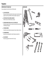 3
3
-
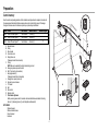 4
4
-
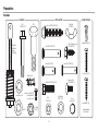 5
5
-
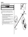 6
6
-
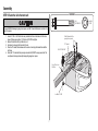 7
7
-
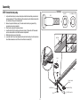 8
8
-
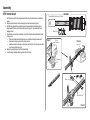 9
9
-
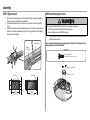 10
10
-
 11
11
-
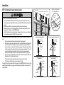 12
12
-
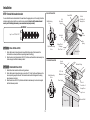 13
13
-
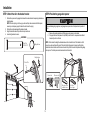 14
14
-
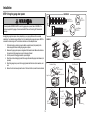 15
15
-
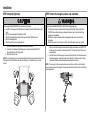 16
16
-
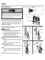 17
17
-
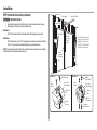 18
18
-
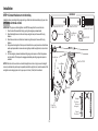 19
19
-
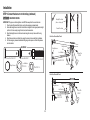 20
20
-
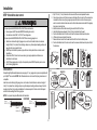 21
21
-
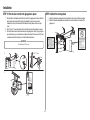 22
22
-
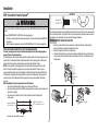 23
23
-
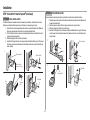 24
24
-
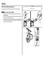 25
25
-
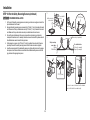 26
26
-
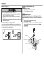 27
27
-
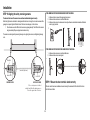 28
28
-
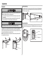 29
29
-
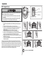 30
30
-
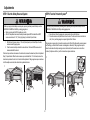 31
31
-
 32
32
-
 33
33
-
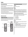 34
34
-
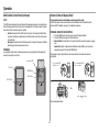 35
35
-
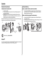 36
36
-
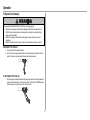 37
37
-
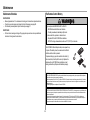 38
38
-
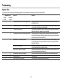 39
39
-
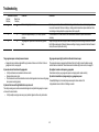 40
40
-
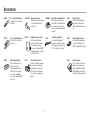 41
41
-
 42
42
-
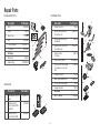 43
43
-
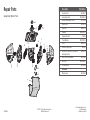 44
44
-
 45
45
-
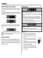 46
46
-
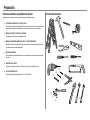 47
47
-
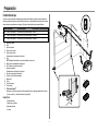 48
48
-
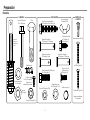 49
49
-
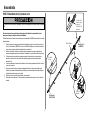 50
50
-
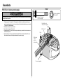 51
51
-
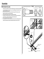 52
52
-
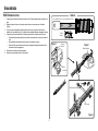 53
53
-
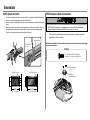 54
54
-
 55
55
-
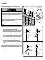 56
56
-
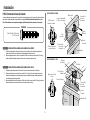 57
57
-
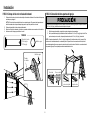 58
58
-
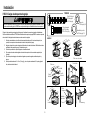 59
59
-
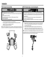 60
60
-
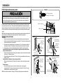 61
61
-
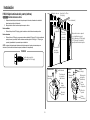 62
62
-
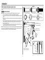 63
63
-
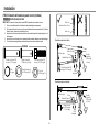 64
64
-
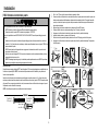 65
65
-
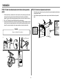 66
66
-
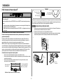 67
67
-
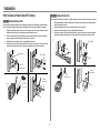 68
68
-
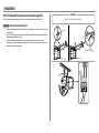 69
69
-
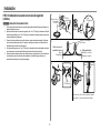 70
70
-
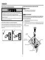 71
71
-
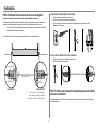 72
72
-
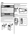 73
73
-
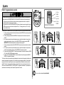 74
74
-
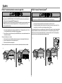 75
75
-
 76
76
-
 77
77
-
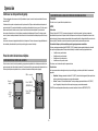 78
78
-
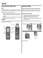 79
79
-
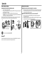 80
80
-
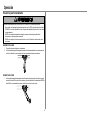 81
81
-
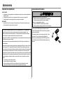 82
82
-
 83
83
-
 84
84
-
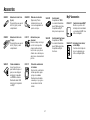 85
85
-
 86
86
-
 87
87
-
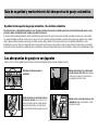 88
88
-
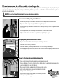 89
89
-
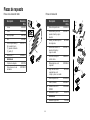 90
90
-
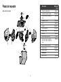 91
91
-
 92
92


Chamberlain B510 Instrucciones de operación
- Categoría
- Abridor de puerta de garage
- Tipo
- Instrucciones de operación
en otros idiomas
Artículos relacionados
-
Chamberlain C870 Instrucciones de operación
-
Chamberlain CIGCWC Internet Connectivity Kit Manual de usuario
-
Chamberlain MYQ-G0301 Guía del usuario
-
-
-
-
-
Chamberlain MyQ-G0201 Manual de usuario
-
-
Otros documentos
-
Craftsman CMXEOCG981 El manual del propietario
-
Craftsman CMXEOCG781 El manual del propietario
-
Craftsman CMXEOCG571 El manual del propietario
-
Craftsman CMXEOCG771 El manual del propietario
-
Craftsman 13954920 El manual del propietario
-
-
-
-
Craftsman 139.3043 El manual del propietario
-
Craftsman CMXEOCG471 El manual del propietario